VisionShare A30 - Wireless pointer NorthVision - Free user manual and instructions
Find the device manual for free VisionShare A30 NorthVision in PDF.


User questions about VisionShare A30 NorthVision
0 question about this device. Answer the ones you know or ask your own.
Ask a new question about this device
Download the instructions for your Wireless pointer in PDF format for free! Find your manual VisionShare A30 - NorthVision and take your electronic device back in hand. On this page are published all the documents necessary for the use of your device. VisionShare A30 by NorthVision.
USER MANUAL VisionShare A30 NorthVision
Wireless Collaboration System
natural_image
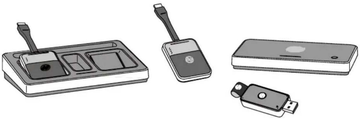
Illustration of four electronic devices: a charging tray, a handheld device, a rectangular device, and a USB flash drive (no text or symbols present)User Manual
A20 / A30 / A40 / A45
Contents
DISCLAIMERS .... 1
WARRANTY....2
SAFETY NOTIFICATIONS....4
FEATURES 7
WHAT IS IN THE PACKAGE 8
A. PRODUCT DESCRIPTION......9
-
Transmitter 9
-
Receiver---- 10
-
Power Station 11
-
USB Wireless Touch Dongle (A30 / A45 ONLY) 12
-
Universal Power Adapter Set 13
B. ESTABLISH YOUR COLLABORATION SYSTEM......14
- Connect the Receiver 14
- Connect the Transmitter 15
2.1 Display Port Adapter 16
2.2 Auxiliary Power Input 16
- Establish the Connection---- 17
- Start Your Presentation---- 18
4.1 Start the Presentation....18
4.2 Pause the Presentation 19
4.3 Standby Mode 20
4.4 Switching Your Presentation Sources 21
- Wireless Touch (A30 / A45 ONLY)---- 22
5.1 Connect the Receiver 23
5.2 Connect and Initiate the Wireless Touch Dongle .....24
C. APPENDIX....26
- Charge Your Transmitter 26
- Receiver Installation---- 27
2.1 Wall Mount installation....27
2.2 Secondary HDMI Output 28
- Configure Your Collaboration System---- 29
3.1 Device Name (Device ID) 30
3.2 Clock Setting....31
3.3 Background 32
3.4 Power Setting 33
3.5 Connection 34
3.6 System....35
- Mirroring360 & 4 Split Screens 41
- Indicator Lights Description 43
- Specification 47
Disclaimers
NorthVision Corporation makes no representations or warranties, either expressed or implied, with respect to the contents hereof and specifically disclaims any warranties, merchantability or fitness for any particular purpose.
Further, NorthVision Corporation reserves the right to revise this publication and to make changes from time to time in the contents hereof without obligation of NorthVision Corporation to notify any person of such revision or changes.
This user manual aims to provide the most updated and accurate information to customers, and thus all contents may be modified from time to time without prior notice. Please visit www.northvision.com for the latest version of this manual.
The illustrations, contents and the images in this guide are for your reference only and subject to change without prior notice.
Warranty
NorthVision warrants the equipment it manufactures to be free from defects in material and workmanship. The procedures presented in this document apply to all NorthVision's VisionShare Series products. All NorthVision brand products purchased by Distributor will receive a three (3) years parts and labor warranty, except for VisionShare transmitters, and all accessories, which hold a one (1) year parts and labor warranty.
The warranties stated above shall be effective upon delivery and remain in effect in accordance with NorthVision's then-current policy. Warranty does not include: (i)Products have been improperly installed, altered or otherwise modified. (ii)Products have been subjected to misuse, abuse, negligence, accident or natural disasters. (iii)Products have been used in a manner contrary to specification.
DOA (Dead on Arrival): The DOA period is 60 days after shipment to an end user. Products that cannot be turned on or cannot display and after testing will be considered DOA. After the DOA product has been tested, please return to the distributor with an RMA number and a replacement will be sent. Products returned that are functioning properly, will be returned to the end user, and the cost of returning the product with normal functions will be borne by the customer. Products returned by DOA should be kept in their original packaging and the accessories must be complete. Otherwise, the products will be considered as RMA (Return as received).
RMA (Returned Material Authorization): Products that fail more than 60 days from the date of shipment but within the warranty period three (3) years require an RMA. During the warranty period, RMA parts and labor costs are included. The customer is responsible for the return of RMA products to the distributor/ NorthVision. Distributor will be responsible for both the shipping method and shipping costs
of RMA products (in the warranty period) for the return. Product determined to be improperly used or damaged by the customer, will incur a maintenance and parts fee. Shipping costs for returning out-of-warranty products is at the customer's expense.
The information in this manual has been carefully checked and is believed to be accurate. However, NorthVision assumes no responsibility for any inaccuracies that may be contained in this manual. In no event will NorthVision be liable for direct, indirect, special, incidental, or consequential damages resulting from any defect or omission in this manual, even if advised of the possibility of such damages. The technical information contained herein regarding the features and specifications are subject to change without notice.
Safety Notifications
- Read the instruction manual carefully before use and save it.
- Use only parts or accessories, (especially power adapters), recommended by the manufacturer. Unapproved parts may be hazardous and cause injuries to the product or users, and will void the warranty.
WARNING:
IF ANY FUNCTIONAL PROBLEMS OR DEFECTS OCCUR WHICH ARE
ATTRIBUTABLE TO
IMPROPER USE OF THE PRODUCT SHALL
VOID THE WARRANTY.
- Refer servicing to qualified personnel only.
- Do not attempt to repair or dissemble the product on your own. Opening or removing cover can expose you to dangerous voltage or other hazards.
- Before plugging the power cord into the AC inlet of the power supply unit, make sure that the voltage applied to the power outlet is within the specified range (100V\~240V). Improper power source voltage range will cause damage to the power supply unit or connected products.
- Power off the product and remove the power adapter while cleaning the product.
- Before powering on the product, make sure all the connectors, cables are firmly installed.
- Don't immerse the battery in water and seawater. Please put it in cool and dry environment if no using.
- Do not use or leave the battery at very high temperature conditions (for example, strong direct sunlight or a vehicle in extremely hot conditions). Otherwise, it can overheat or fire or its performance will be degenerated and its service life will be decreased. It is recommended that you use the battery within the ambient temperatures range of 15-30 degrees.
- First Time Battery Charge: Charge the transmitters for six hours before first-time use.
Important Safety Notifications
- Do not expose the product to liquids or moisture, such as a bathtub, a washbowl, a kitchen sink, a laundry tub, and a swimming pool.
- Do not expose the product, including the devices and accessories, under direct sunlight, and keep it away from any heat source.
- Do not bend the cables of the devices, or place them to the unstable locations.
Always install and operate the devices in flat and secure location.
- Do not place the product on an unstable location, stand or table. If the machine falls, it may injure a person or cause serious damage to the appliance.
- Do not allow anything to rest on the power cord. Do not locate the product where people may walk on the cord.
- Do not make the power outlet and extension cords overload. Overload can result in fire or electric shock.
-
If any of the following situations occurs, unplug the product from the power outlet immediately and consult with a qualified service person:
-
The power cord or plug is damaged or frayed.
- Liquid is spilled on the product.
- The product is dropped or damaged.
- Use a soft cloth to clean the product when it is dirty. In case of stubborn dirt, use a mild detergent and wipe the product gently. Always turn off and unplug the product before cleaning.
- Please clean and store the products and accessories with care, when the product is not use.
Features
Wireless Collaboration Solution
Perfect Combination with Touch Display For Conference Room


HDMI Plug & PLAY
Compatible with all HDMI connectivity. Intuitive True Plug & Play
Near Zero Latency
Cable-like experience by instant transmission < 0.1 ms
No WiFi Interference
Free from 2.4GHz and 5GHz WiFi signal interference.

4K Video Quality
High performance of 4K video quality without compression loss.
Easy Installation
Simple HDMI connectivity. Intuitive set up without software installation.
Power Embedded
Solves power and cabling issues.
What is in the package
natural_image
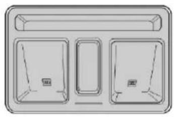
Simple line drawing of a three-panel cabinet or rack unit (no text or symbols)Power Station
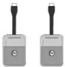
natural_image
Two identical gray electronic device lockers with black leads and circular buttons, shown side by side (no text or symbols visible)Transmitter X 2
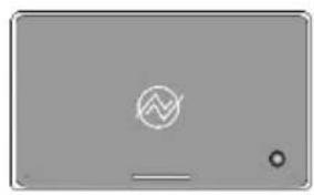
natural_image
Generic tablet device with a logo and control buttons (no readable text or symbols)Receiver

Mini DP to HDMI
Adapter
HDMI Cable
Micro USB Cable


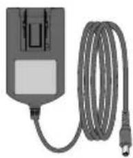
natural_image
Electric shock absorber with attached cable (no visible text or symbols)Universal Power Adapter Set x 2
text_image
Vitron Share Series Vitron® Interactive space System installation name: VITRON 2014-006-005 Voltage Power Battery Battery Type: High Battery Color: Black Battery Color: BlackQuick Installation Guide
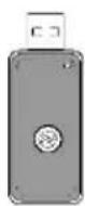
USB Wireless Touch
Dongle*
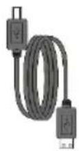
Touch USB Cable* (Type A to Type B)
* USB Wireless Touch Dongle and Touch USB Cable (Type A to Type B) are included in A30 and A45 ONLY
A. Product Description
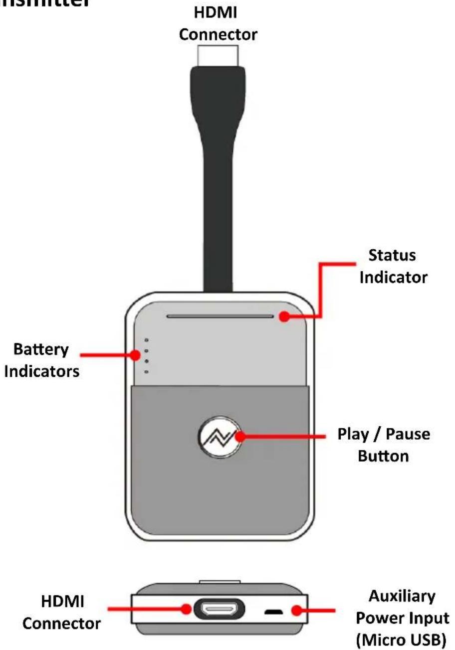
1. Transmitter
text_image
HDMI Connector Status Indicator Battery Indicators Play / Pause Button HDMI Connector Auxiliary Power Input (Micro USB)● First Time Battery Charge:
Charge the transmitters for six (6) hours before first-time use.
● Auxiliary Power Input:
Use the supplied Micro USB cable to obtain power from laptop or PC. Please refer to Auxiliary Power Input.
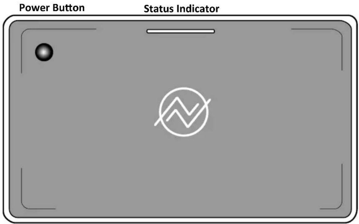
2. Receiver
text_image
Power Button Status Indicator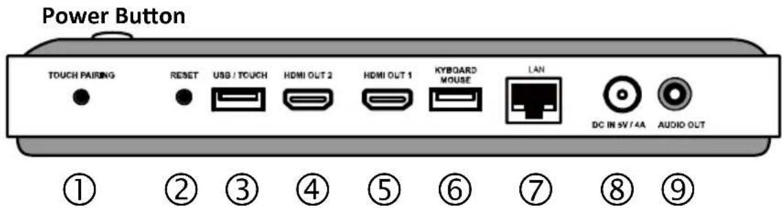
text_image
Power Button TOUCH PAIRING RESET USB / TOUCH HDMI OUT 2 HDMI OUT 1 KYBOARD MOUSE LAN DC IN 5V / 4A AUDIO OUT ① ② ③ ④ ⑤ ⑥ ⑦ ⑧ ⑨① Touch Pairing
② Reset
③ USB / Touch
④ HDMI OUT 2
⑤ HDMI OUT 1
⑥ Keyboard / Mouse
⑦ LAN
⑧ DC IN (5V / 4A)
⑨ AUDIO OUT
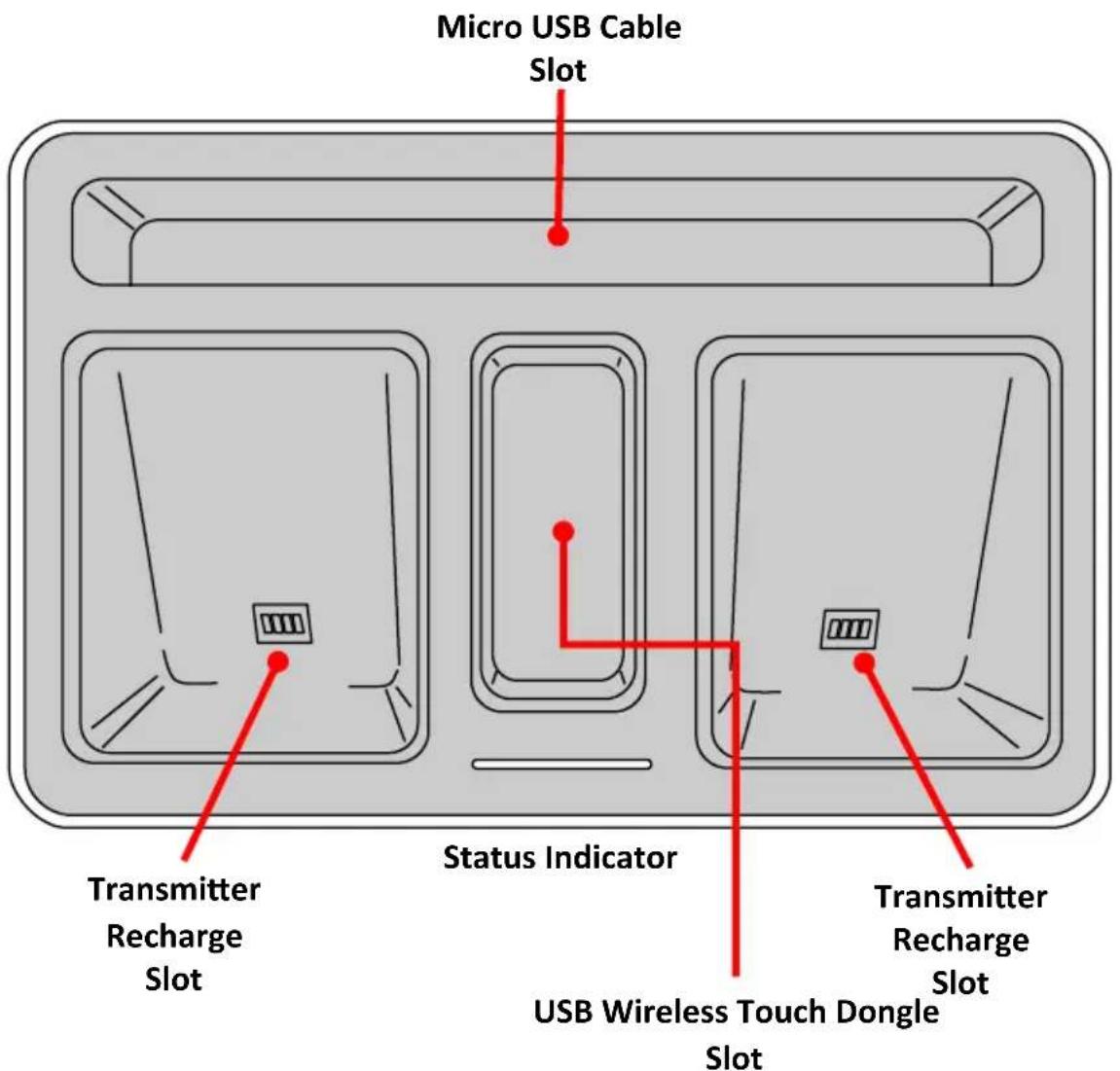
3. Power Station
text_image
Micro USB Cable Slot Transmitter Recharge Slot Status Indicator USB Wireless Touch Dongle Slot Transmitter Recharge Slot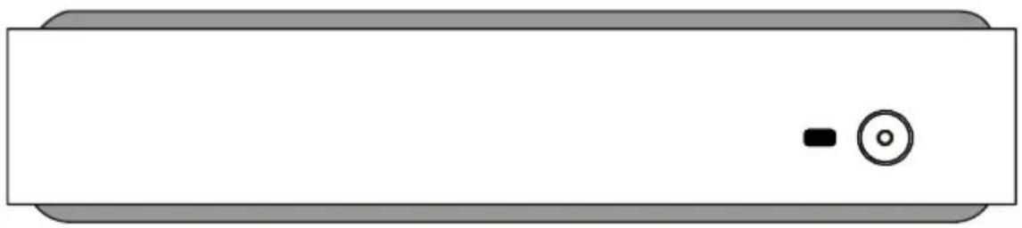
natural_image
Simple diagram of a rectangular device with a black square and circular button on the side (no text or symbols)4. USB Wireless Touch Dongle (A30 / A45 ONLY)
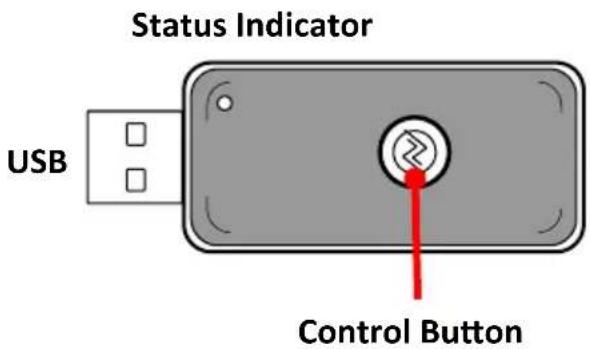
text_image
Status Indicator USB Control Button5. Universal Power Adapter Set
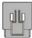
US Plug Adapter
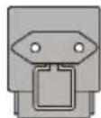
EU Plug Adapter
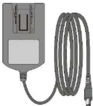
natural_image
Illustration of a connected electrical device with a coiled cable (no text or symbols visible)Power Adapter
◆ Change the Plug Adapter
To install the plug adapter:
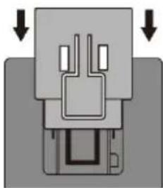
natural_image
Pure mechanical component diagram without any text, numbers, or symbols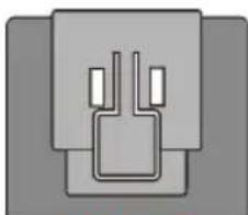
natural_image
Pure electrical connector diagram without any text or symbolsClick!!
To detach the plug adapter:
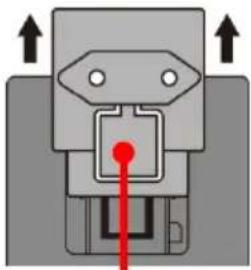
natural_image
Pure mechanical component diagram without any text, numbers, or symbolsSnap-In Latch
Note:
- Make sure the plug adapter is firmly installed before plugging the power adapter to the power outlet.
- Store the unused plug adaptor securely for future use.
B. Establish Your Collaboration System
1. Connect the Receiver
- Connect the power adapter to the power outlet and Receiver.
- Connect the cable of HDMI to the Receiver and display device.
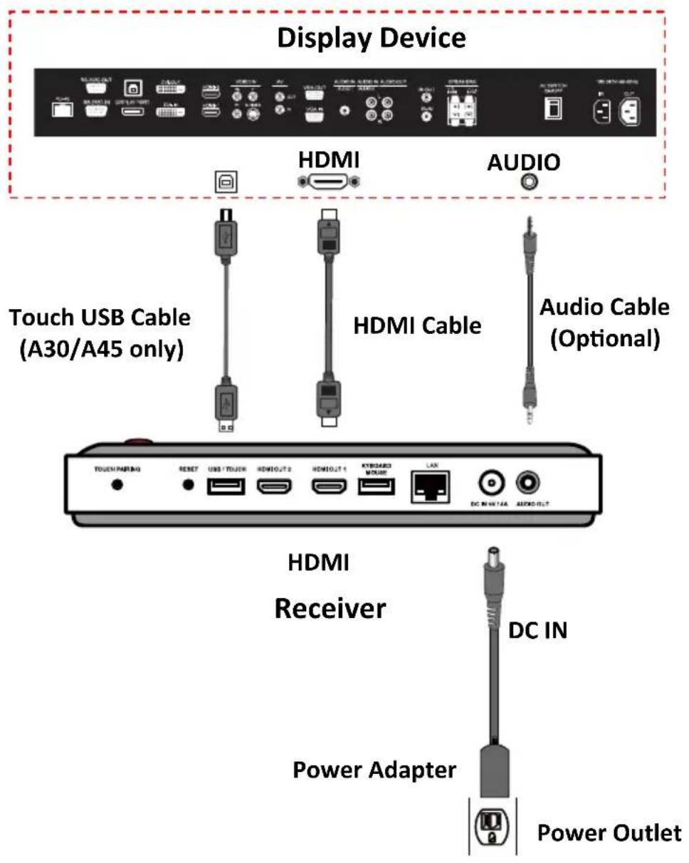
text_image
Display Device HDMI AUDIO Touch USB Cable (A30/A45 only) HDMI Cable Audio Cable (Optional) HDMI Receiver DC IN Power Adapter Power Outlet2. Connect the Transmitter
- Connect the Transmitter to the laptop or PC.
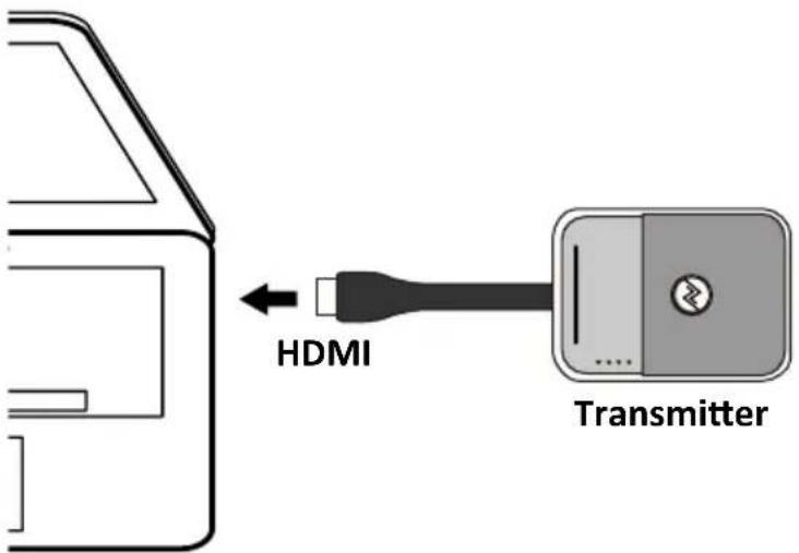
text_image
HDMI Transmitter- The Transmitter flashes RED and then turns BLUE to search for the Receiver.
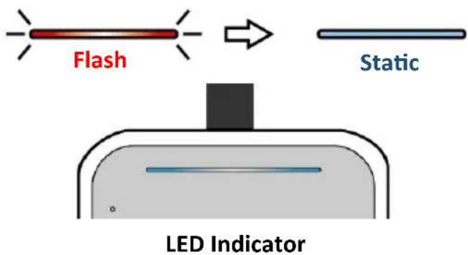
text_image
Flash Static LED Indicator2.1 Display Port Adapter
You can use the HDMI to Display Port (DP) adapter and connect to the display port. Other adapters and dongles may be used but NorthVision is unable to guarantee their performance.
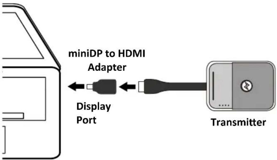
text_image
miniDP to HDMI Adapter Display Port Transmitter2.2 Auxiliary Power Input
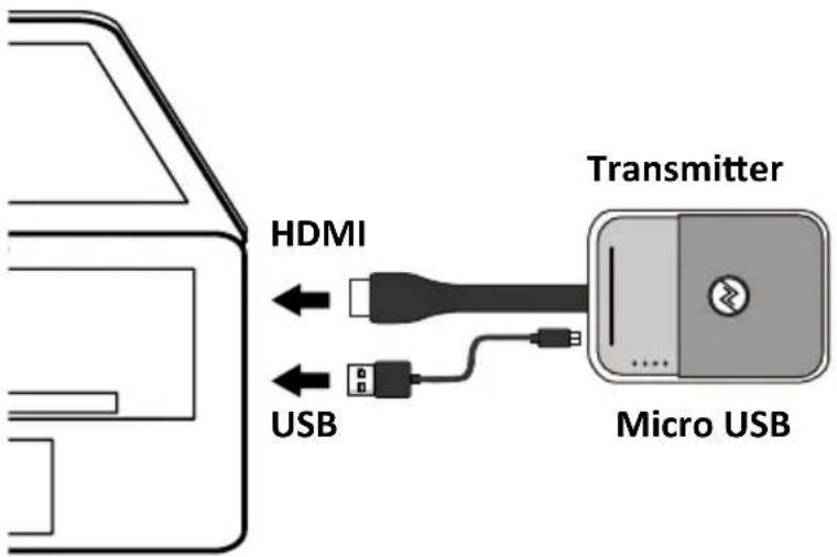
You can use the supplied micro USB cable to obtain power for presentation and battery-charging.
text_image
HDMI USB Transmitter Micro USB3. Establish the Connection
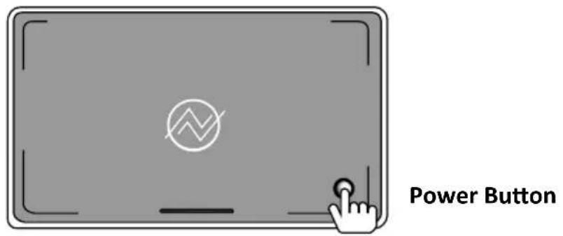
- Press the power button on the Receiver.
text_image
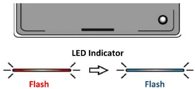
Power Button- The Receiver flashes RED and flash BLUE to sync to the Transmitter.
text_image
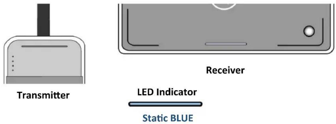
LED Indicator Flash → Flash- Once the pairing of Transmitter and Receiver is established, the indicators of the Transmitter and Receiver show static BLUE light and are ready for presentation.
text_image
Transmitter Receiver LED Indicator Static BLUE4. Start Your Presentation

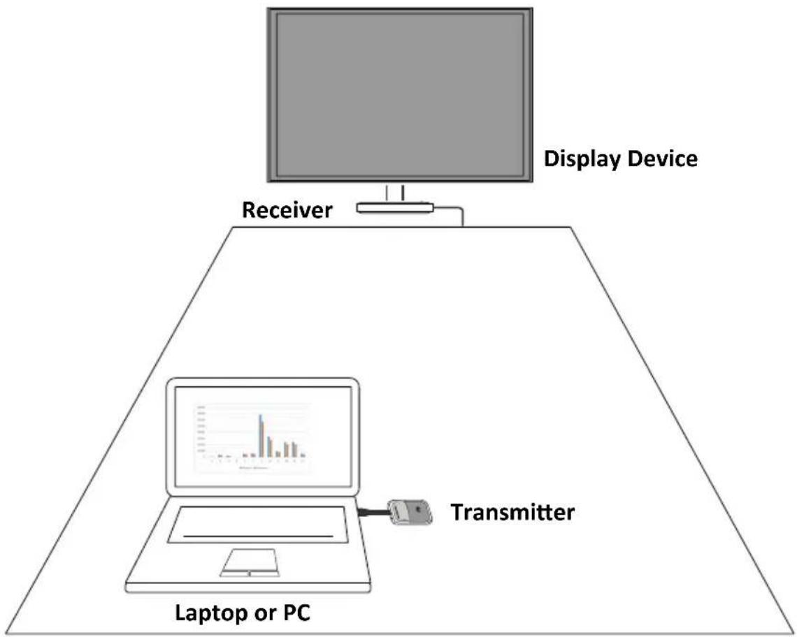
flowchart
graph TD
    A["Laptop or PC"] --> B["Receiver"]
    B --> C["Display Device"]
    C --> D["Bar Chart 1"]
    C --> E["Bar Chart 2"]
    C --> F["Bar Chart 3"]
    C --> G["Bar Chart 4"]
    C --> H["Transmitter"]
    style A fill:#f9f,stroke:#333
    style B fill:#ccf,stroke:#333
    style C fill:#cfc,stroke:#333
    style D fill:#fcc,stroke:#333
    style E fill:#cff,stroke:#333
    style F fill:#ffc,stroke:#333
    style G fill:#cfc,stroke:#333
    style H fill:#fcc,stroke:#333
4.1 Start the Presentation
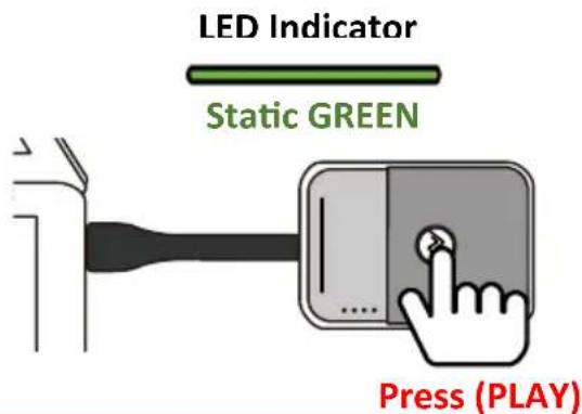
Press the PLAY button of the transmitter to start the presentation. The status LED indicator of Receiver and Transmitter show static GREEN while the presentation is in progress.
text_image
LED Indicator Static GREEN Press (PLAY)4.2 Pause the Presentation
flowchart
graph TD
    A["Monitor"] --> B["Receiver"]
    B --> C["Laptop or PC"]
    C --> D["Display Device"]
    D --> E["Transmitter"]
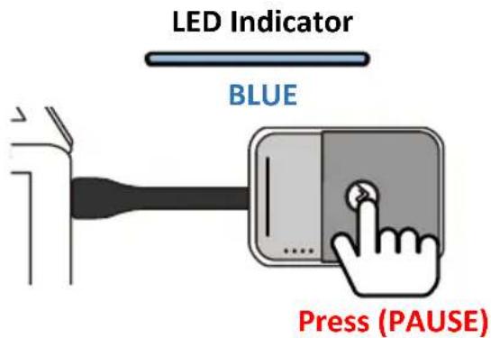
Press the PLAY/PAUSE button of the Transmitter to pause the presentation.
The LED indicator turns to BLUE as the presentation is paused.
text_image
LED Indicator BLUE Press (PAUSE)4.3 Standby Mode
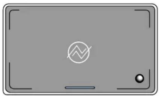
The receiver may switch to standby mode automatically. (Please refer to Power Setting at setting page for further instruction).
natural_image
Gray rectangular device with a white circular symbol and a small dot at the bottom, no text or labels present.Power Button (Flashing)
Receiver
Press the power button to wake up the receiver.
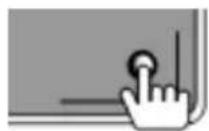
Power Button
(Press and Wake-Up)
4.4 Switching Your Presentation Sources
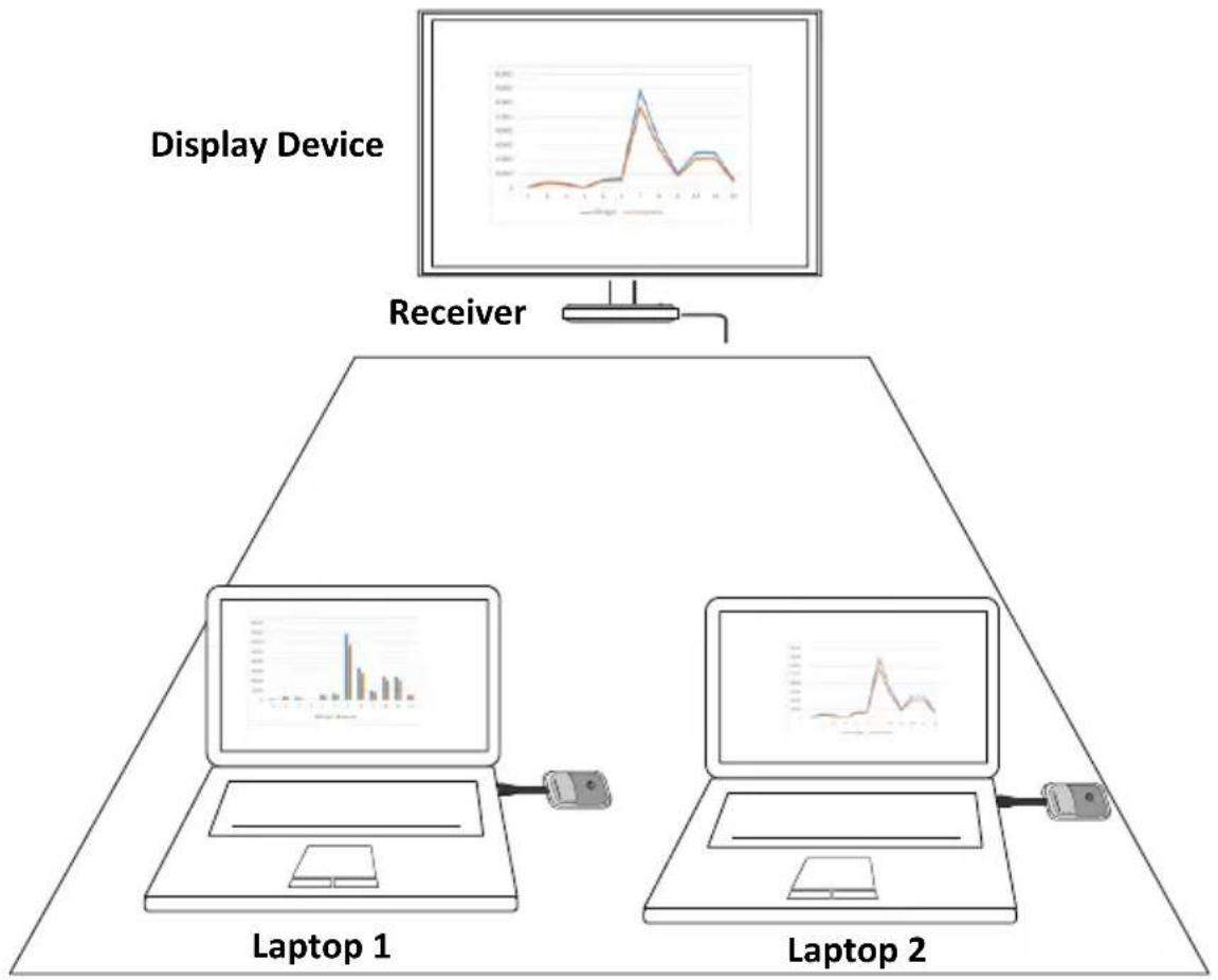
flowchart
graph TD
    A["Receiver"] --> B["Laptop 1"]
    A --> C["Laptop 2"]
    B --> D["Display Device"]
    C --> D
    style A fill:#f9f,stroke:#333
    style B fill:#ccf,stroke:#333
    style C fill:#ccf,stroke:#333
Press the PLAY button of Transmitter 1 or Transmitter 2 to switch the presentation sources (laptop 1 or laptop 2). Handshaking takes a few seconds, and then the displayed image will switch.
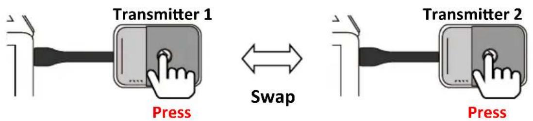
text_image
Transmitter 1 Press Swap Transmitter 2 Press5. Wireless Touch (A30 / A45 ONLY)
VisionShare with touch display allows bi-directional wireless touch functions, with full control back to the PC/laptop simultaneously.
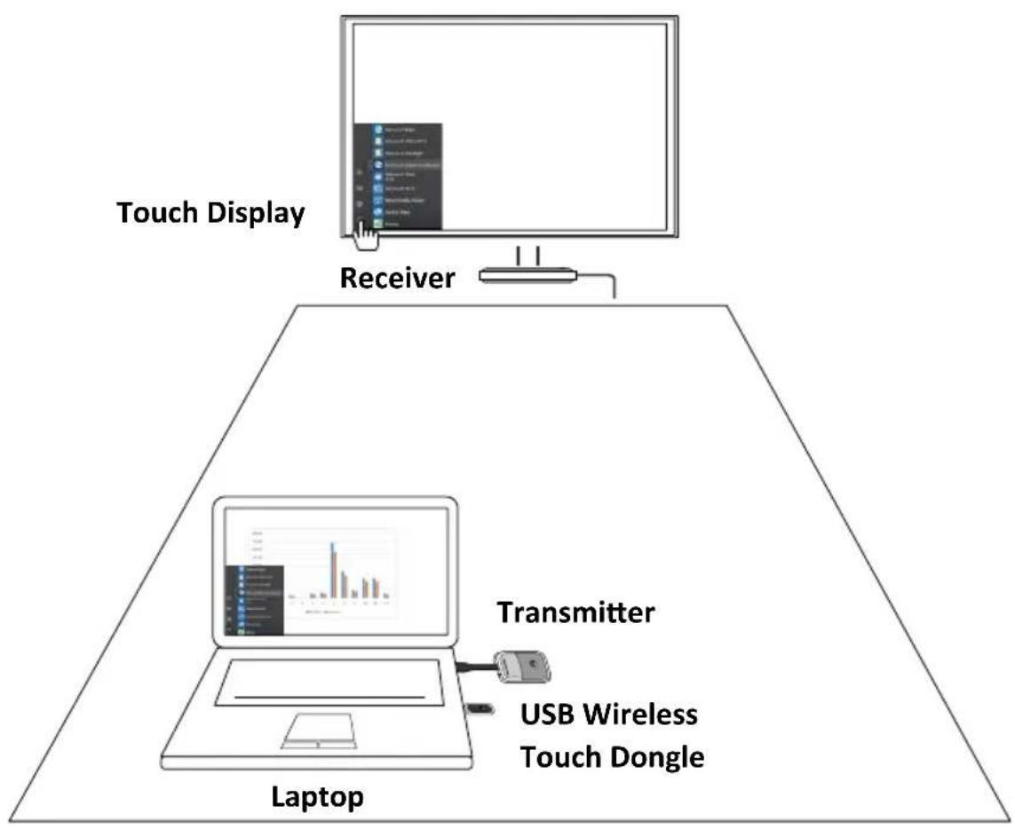
flowchart
graph TD
    A["Touch Display"] --> B["Receiver"]
    B --> C["Laptop"]
    C --> D["Transmitter"]
    D --> E["USB Wireless Touch Dongle"]
* Wireless Touch function may have compatibility issue cause by different panel touch drive. Please contact your local agency or service@NorthVision.com
5.1 Connect the Receiver
- Make sure the Transmitter and Receiver are connected and the collaboration system is established.
- Make sure the touch USB cable is connected to the touch display properly.
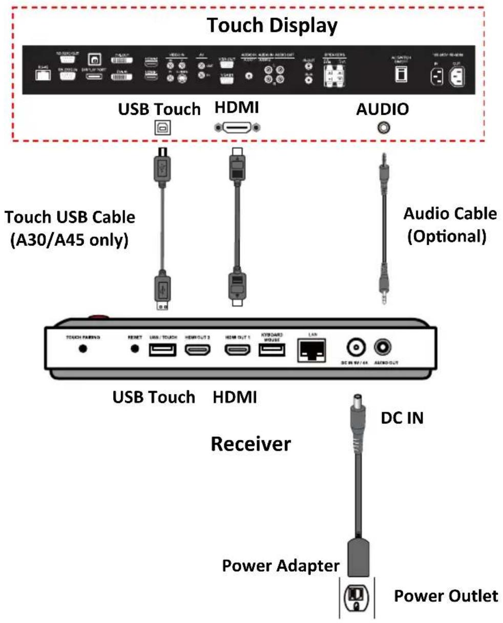
text_image
Touch Display USB Touch HDMI AUDIO Touch USB Cable (A30/A45 only) Audio Cable (Optional) USB Touch HDMI Receiver DC IN Power Adapter Power Outlet5.2 Connect and Initiate the Wireless Touch Dongle
- Connector the USB wireless touch dongle to the USB port of the laptop or PC.
- Press the control button on the touch dongle to activate the wireless touch function.
The screen of the laptop is synchronized with touch display.
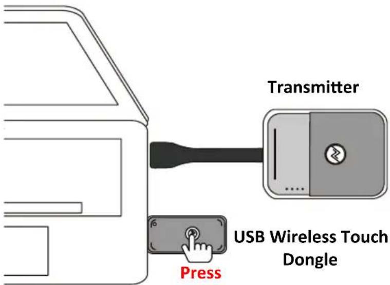
text_image
Transmitter USB Wireless Touch Dongle Press- VisionShare touch provides bi-directional control back to the PC or laptop. Using the touch display you may open files, writing, resize the image, etc. from your PC or laptop.
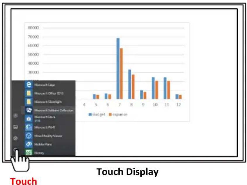
bar
| Touch | Budget | expianise | | :--- | :--- | :--- | | 4 | 0 | 0 | | 5 | 10000 | 8000 | | 6 | 10000 | 9000 | | 7 | 68000 | 56000 | | 8 | 33000 | 27000 | | 9 | 12000 | 11000 | | 10 | 24000 | 22000 | | 11 | 24000 | 22000 | | 12 | 8000 | 7000 | Touch Display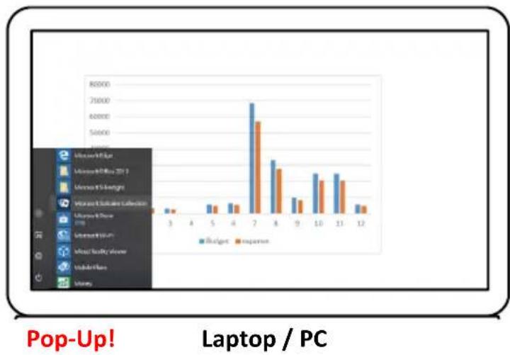
bar
| Category | Budget () | Expansion () | | :--- | :--- | :--- | | 3 | 1000 | 500 | | 4 | 1000 | 500 | | 5 | 2000 | 1500 | | 4 | 2000 | 1500 | | 2 | 70000 | 60000 | | 8 | 40000 | 35000 | | 9 | 15000 | 12500 | | 10 | 35000 | 32500 | | 21 | 35000 | 32500 | | 12 | 15000 | 12500 | Pop-Up! Laptop / PCC. Appendix
1. Charge Your Transmitter
- Place the power station on the designated location (e.g. conference table).
- Connect the power adapter set to the charging dock and power outlet.
- Place the transmitters in the slots of power station. A flashing light indicates that the transmitters are charging.
- When the battery is fully charged, remove the transmitter (s) from the power station.
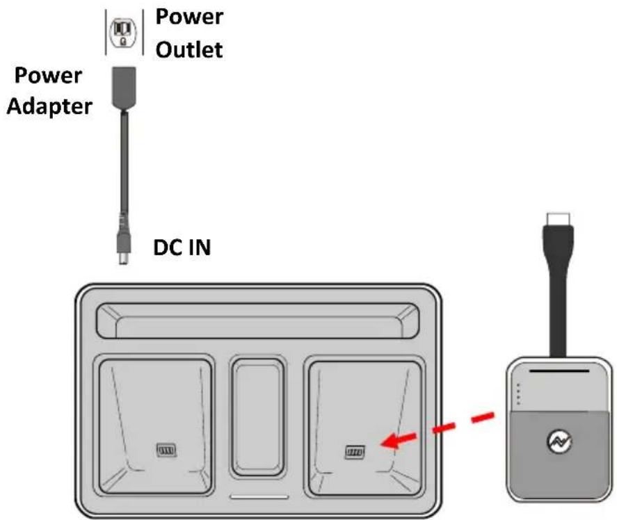
text_image
Power Adapter Power Outlet DC INInstall the Transmitter to the Power Station
Important: First Time Battery Charge Charge the transmitters for six hours before first-time use.
2. Receiver Installation
2.1 Wall Mount installation
You can install the receiver onto a wall or ceiling.
To install the Receiver on the wall:
- Use two wall-plugs and screws and install to the location.
- There are two hook slots in the bottom of receiver.
Mount the receiver on the wall and make sure it is secured. - Connect the power adapter set to the receiver and power outlet.
- Do not place the receiver in a closed cabinet.
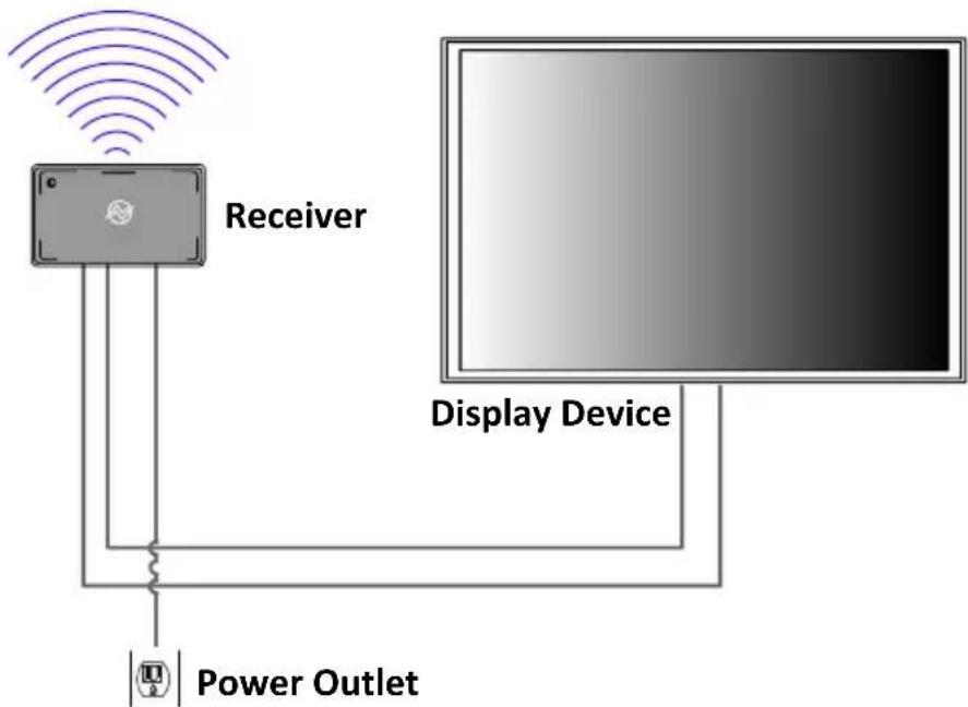
text_image
Receiver Display Device Power OutletNote:
● Install the receiver to a flat and stable location.
- Select the proper plug adapter and install to the power adapter.
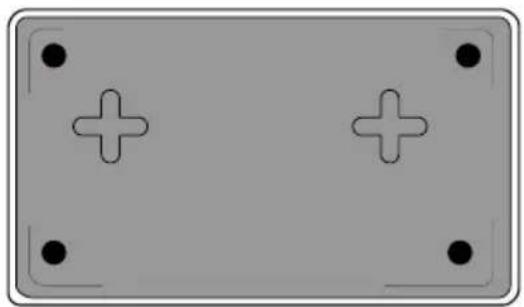
natural_image
Pure electrical circuit lines without any symbolsWall Mount Opening of Receiver (Bottom)
2.2 Secondary HDMI Output
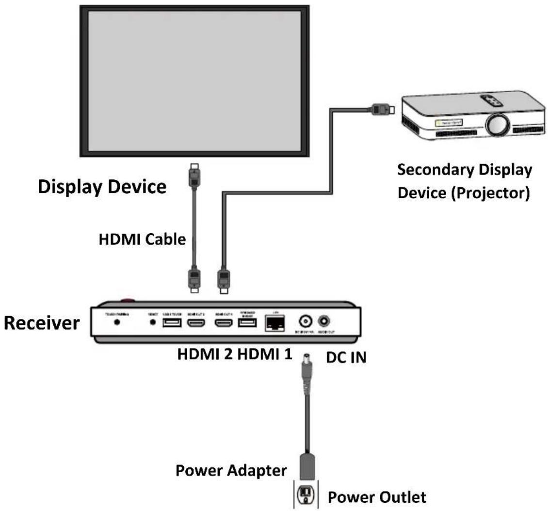
text_image
Display Device HDMI Cable Secondary Display Device (Projector) Receiver HDMI 2 HDMI 1 DC IN Power Adapter Power Outlet3. Configure Your Collaboration System
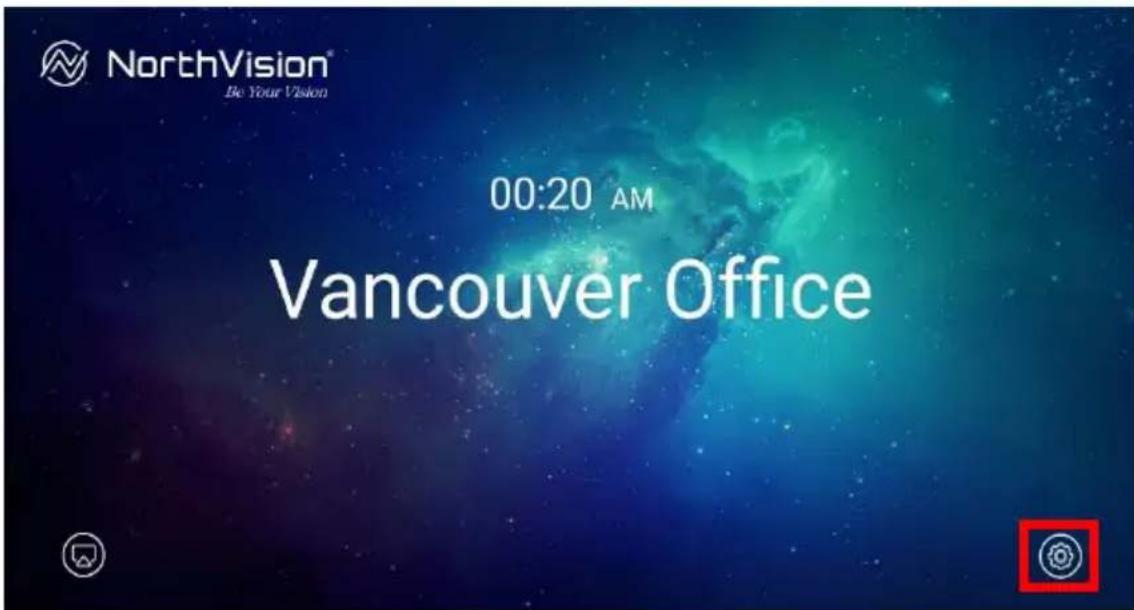
text_image
NorthVision® Be Your Vision 00:20 AM Vancouver OfficeClick the setting icon (red marker) to configure the VisionShare system settings such as Device Name (Device ID), Clock Setting, Background, Power Setting, Connection and System:
3.1 Device Name (Device ID)
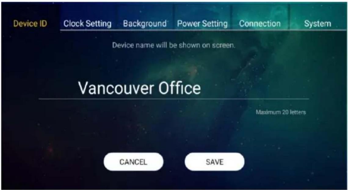
text_image
Device ID Clock Setting Background Power Setting Connection System Device name will be shown on screen. Vancouver Office Maximum 20 letters CANCEL SAVEEach device is assigned an exclusive ID (name) for management.
=> Type the name of the device.
=> Click "SAVE" to confirm.
3.2 Clock Setting
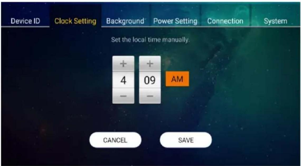
text_image
Device ID Clock Setting Background Power Setting Connection System Set the local time manually. + 4 09 - - AM CANCEL SAVESetting the local time manually for the device.
=> Click "+", "-" and "AM/PM" to set the proper local time.
=> Click "SAVE" to confirm.
3.3 Background
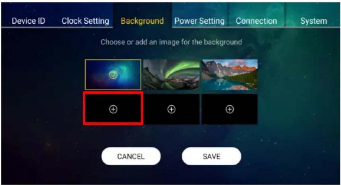
text_image
Device ID Clock Setting Background Power Setting Connection System Choose or add an image for the background CANCEL SAVEClick on the red marker to import and select the background image via USB drive for your device.
=> Select the image.
=> Click "SAVE" to confirm.
3.4 Power Setting
text_image
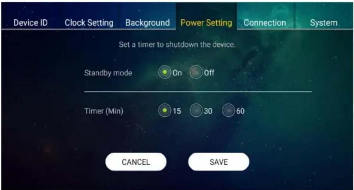
Device ID Clock Setting Background Power Setting Connection System Set a timer to shutdown the device. Standby mode On Off Timer (Min) 15 30 60 CANCEL SAVESetting a timer to standby mode if the device is not functioning during the designate time.
=> Click "On" to activate the standby mode.
=> Select the timer (countdown time).
=> Click "SAVE" to confirm.
3.5 Connection
text_image
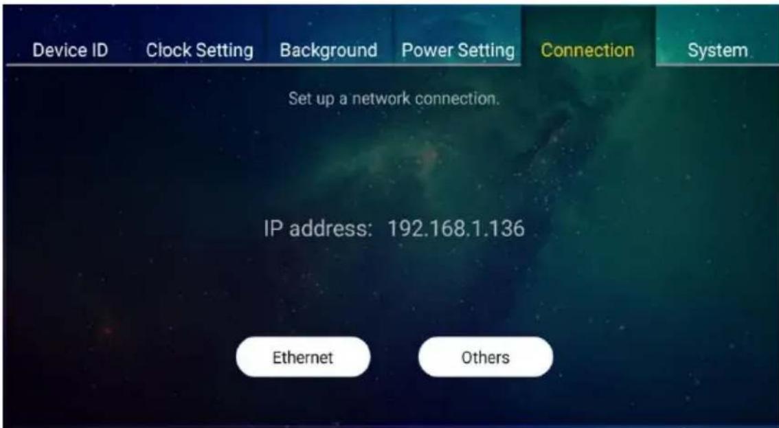
Device ID Clock Setting Background Power Setting Connection System Set up a network connection. IP address: 192.168.1.136 Ethernet OthersIP address will show on the screen automatically after plug in LAN cable.
=> Or, please click "Ethernet" button to set "DHCP" or "Static IP" manually.
=> Or, please click "Others" to set to other settings.
3.6 System
text_image
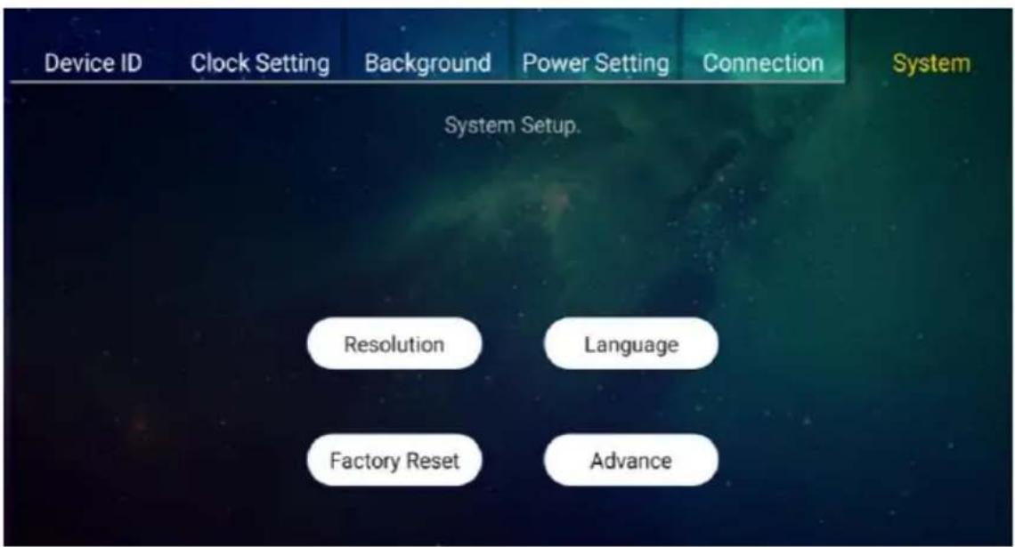
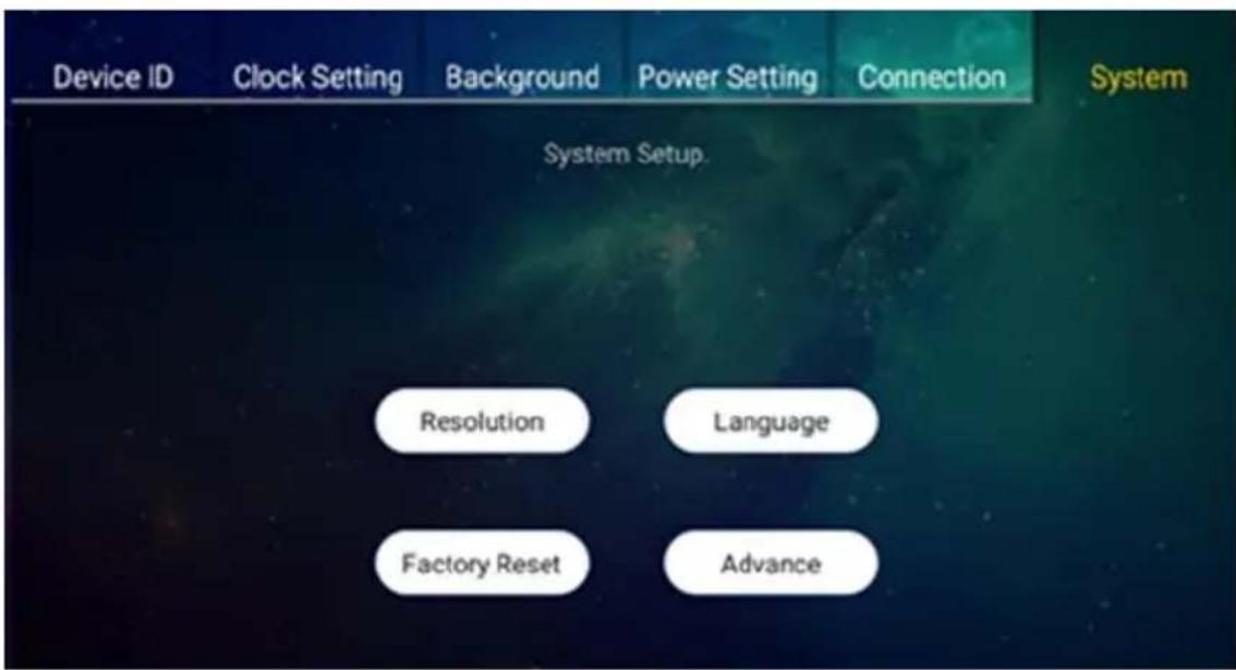
Device ID Clock Setting Background Power Setting Connection System Setup. Resolution Language Factory Reset AdvanceTo configure the basic function on the device, include “Resolution”; “Language”; “Factory Reset” and “Advance” function.
- Resolution
text_image
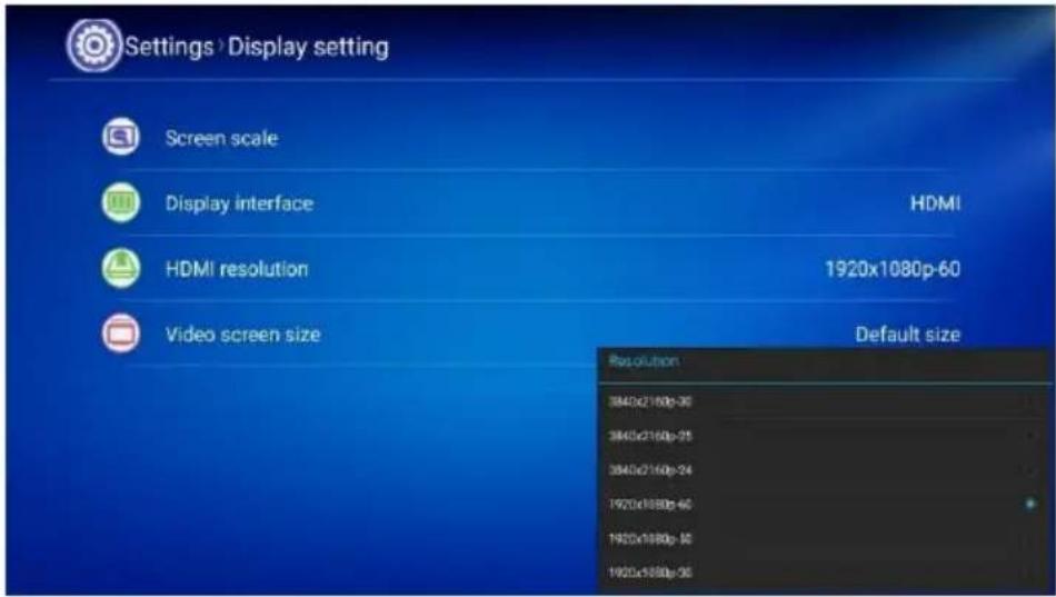
Settings Display setting Screen scale Display interface HDMI HDMI resolution 1920x1080p-60 Video screen size Default size Resolution 3840x2160p-30 3840x2160p-25 3840x2160p-24 1920x1080p-60 1920x1080p-50 1920x1080p-30Resolution: adjust the aspect ratio screen scale, display interface, HDMI resolution and video screen size. Various resolutions can be selected.
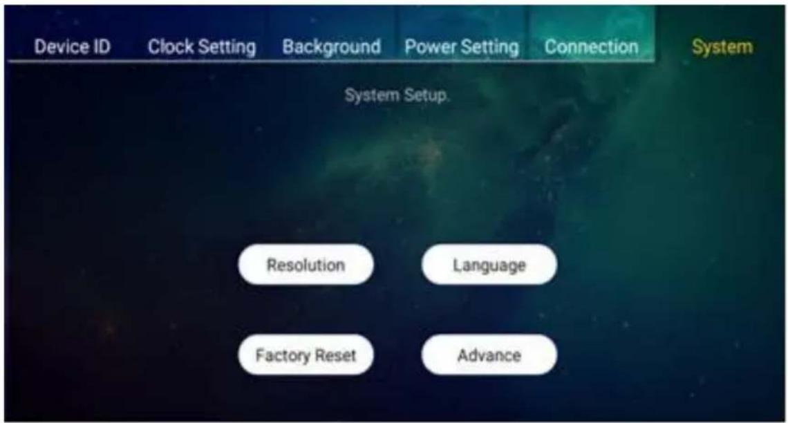
- Language
text_image
Device ID Clock Setting Background Power Setting Connection System System Setup. Resolution Language Factory Reset AdvanceLanguage: language setting of the device.
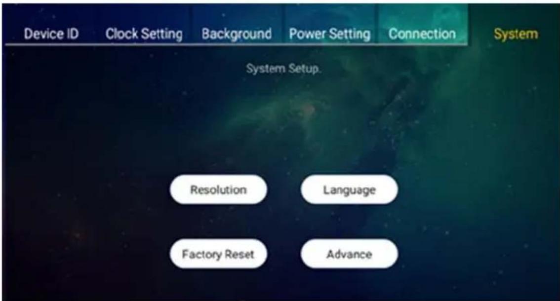
● Factory Reset
text_image
Device ID Clock Setting Background Power Setting Connection System Setup. Resolution Language Factory Reset AdvanceFactory Reset: restore the device to the default settings
- Advance
text_image
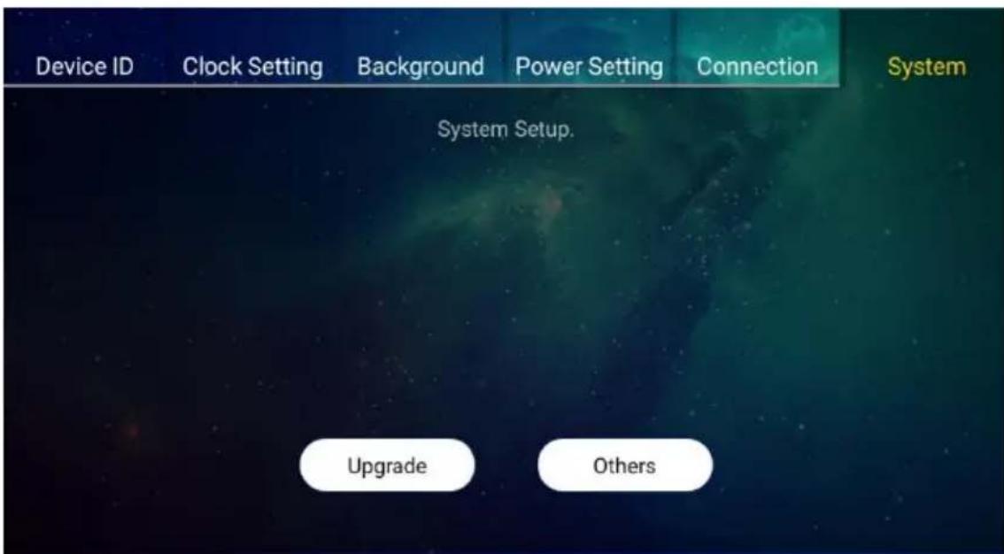
Device ID Clock Setting Background Power Setting Connection System Setup. Resolution Language Factory Reset AdvanceAdvance: click "Upgrade" to upgrade the system.
Click "Others" can see the "FileExplorer" and "Apps" on the device.
text_image
Device ID Clock Setting Background Power Setting Connection System System Setup. Upgrade Others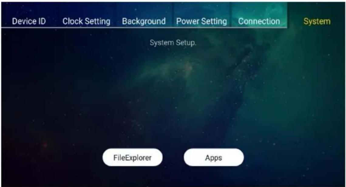
text_image
Device ID Clock Setting Background Power Setting Connection System System Setup. FileExplorer Apps4. Mirroring360 & 4 Split Screens
text_image
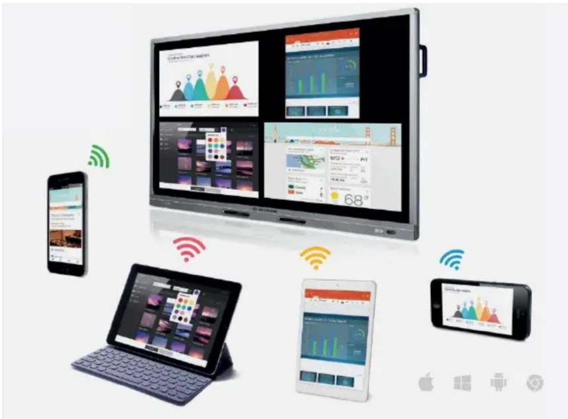
Digital health and tech ecosystem diagram showing smart home devices, mobile devices, and connectivity icons with Chinese labelsYou can use the Receiver of the VisionShare System to mirror your device(s) to the TV.
- Turn on the power switch of the TV.
- Turn on the receiver of the VisionShare collaboration system.
- Operate your device and activate the mirroring function.
- Find the "mirror display device" and follow the instructions to connect.
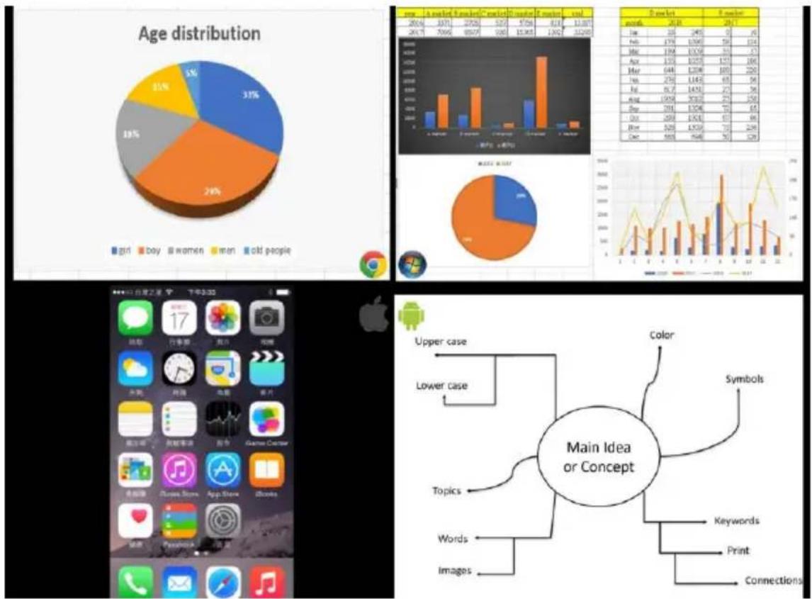
5. Multiple Split-Screen:
The VisionShare system can supply multiple device connection for up to 4 devices.
bar
Age distribution | Category | Percentage (%) | | :--- | :--- | | girl | 35 | | boy | 24 | | women | 18 | | men | 15 | | old people | 5 | | Market Data (units) | Number of users | | :--- | :--- | | Jan | 20 | | Feb | 24 | | Mar | 27 | | Apr | 19 | | May | 15 | | Jun | 13 | | Jul | 12 | | Aug | 11 | | Sep | 10 | | Oct | 9 | | Nov | 8 | | Dec | 7 | | Market Size (units) | Number of users | | :--- | :--- | | Jan | 20 | | Feb | 24 | | Mar | 27 | | Apr | 19 | | May | 15 | | Jun | 13 | | Jul | 12 | | Aug | 11 | | Sep | 10 | | Oct | 9 | | Nov | 8 | | Dec | 7 | | Market Size / Sales (units) | Number of users | | :--- | :--- | | Jan | 20 | | Feb | 24 | | Mar | 27 | | Apr | 19 | | May | 15 | | Jun | 13 | | Jul | 12 | | Aug | 11 | | Sep | 10 | | Oct | 9 | | Nov | 8 | | Dec | 7 | | Market Size/Units (units) | Number of users | | :--- | :--- | | Jan | 20 | | Feb | 24 | | Mar | 27 | | Apr | 19 | | May | 15 | | Jun | 13 | | Jul | 12 | | Aug | 11 | | Sep | 10 | | Oct | 9 | | Nov | 8 | | Dec | 7 | | Market Size (units) / Sales ( units) | Number of users | | :--- | :--- | | Jan | 20 | | Feb | 24 | | Mar | 27 | | Apr | 19 | | May | 15 | | Jun | 13 | | Jul | 12 | | Aug | 11 | | Sep | 10 | | Oct | 9 | | Nov | 8 | | Dec | 7 | | Market Size (units / sales) / Sales ( units) | Number of users | | :--- | :--- | | Jan | 20 | | Feb | 24 | | Mar | 27 | | Apr | 19 | | May | 15 | | Jun | 13 | | Jul | 12 | | Aug | 11 | | Sep | 10 | | Oct | 9 | | Nov | 8 | | Dec | 7 |Upper case
Lower case Topics Words Images Color Symbols Keywords Print ConnectionsFor Android:
Make sure you have installed the Mirroring360 on your Android device. You can download it from the Play Store.

Mirroring360
https://www.northvision.com/download
5. Indicator Lights Description
Transmitter
| Status | LED Indicator | Description |
| OFF |  | The Transmitter is not connected. |
| Auto-Pairing |  | The Transmitter is connected and then auto-pairing to the Receiver. |
| Auto-Pairing Success & Stand By |  Static BLUE Static BLUE | The connection between Transmitter and the Receiver is established.The Transmitter is ready for presentation.Press the PLAY/PAUSE button to start presentation. |
| Presentation |  | Presentation is proceeding.Press the PLAY/PAUSE button to pause presentation. |
| Pause |  Static BLUE Static BLUE | Presentation is paused. No content sent to the display device.Press the PLAY/PAUSE button again to resume presentation. |
| ERROR |  | The Transmitter is in error or is not functioning properly. |
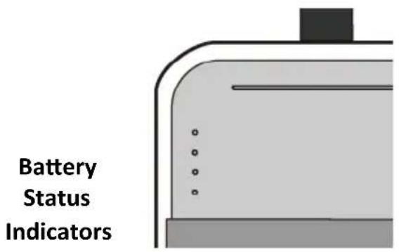
Transmitter - Battery Status Indicator
text_image
Battery Status Indicators| Battery Status Indicators | Description |
| The four LED indicators indicate the battery capacity of the Transmitter: Four LED: fully charged (100%). Three LED: the battery capacity is I about 75%. Two LED: the battery capacity is about 50%. One LED (LOW BATTERY): the battery capacity is about 25 % and needs charging immediately. |
TIP: Check the Battery Capacity
- When the transmitter is not connected, press the PLAY/PAUSE button to check the battery capacity.
- When the transmitter or the micro USB connector for battery-charge is connected, the battery indicators light automatically to indicate the battery status.
Important: First Time Battery Charge
Charge the transmitters for six hours before first-time use.
Receiver
| Status | LED Indicator | Description |
| OFF |  | The Receiver is power-off. |
| Auto-Pairing |  | The Receiver is pairing with the Receiver. |
| Auto-Pairing Success & Stand By |  Static BLUE Static BLUE | The connection between Transmitter and the Receiver is established. |
| Presentation |  | Presentation is proceeding. |
| Pause |  Static BLUE Static BLUE | Presentation is paused. |
| ERROR |  Flashing RED Flashing RED | The Receiver is in error or is not functioning properly. |
Receiver - Power Button (with White LED Indicator)
| Power Button(Indicator) | Status | Description |
 |  Power-OFF Power-OFF | The Receiver is power-off. |
 Static White Static White | The Receiver is powered on. | |
 Flashing White Flashing White | The Receiver is in standby mode.Press the power button to wake up the receiver. |
Power Station
| Status | LED Indicator | Description |
| OFF |  | The Power Station is off. |
| Standby |  Static BLUE Static BLUE | The Power Station is connected and ready for battery charge. |
| Battery Charge |  flashing BLUE flashing BLUE | The Power Station is in battery charge process. |
| Battery Charge Full |   | The Transmitter is fully charged. |
| ERROR |   | The Power Station is in error or is not functioning properly. |
USB Wireless Touch Dongle
| Status | LED Indicator | Description |
| Power-OFF |  | The USB Wireless Touch Dongle is not connected to the computer. |
| Pairing |  Flashing BLUE Flashing BLUE | The USB Wireless Touch Dongle is paring with the receiver. |
| Pairing Success |  Static BLUE Static BLUE | The USB Wireless Touch Dongle has established the connection to the receiver. |
| Play |  Static GREEN Static GREEN | The USB Wireless Touch Dongle is functioning properly. |
| Error |  Flashing GREEN and BLUE Flashing GREEN and BLUE | The USB Wireless Touch Dongle is in error and not functioning. |
- Specification
| Model Name | A20 | A30 | A40 | A45 |
| Input Resolution | up to 1920 x 1080 @ 60Hz | up to 4K x 2K (3840 x 2160 @ 30Hz) | ||
| Video Quality | Uncompressed content | |||
| Frame Rate | up to 1920 x 1080 60 fps | up to 3840 x 2160 30 fps | ||
| Support Platform | Windows, Mac, Chrome, Any OS support HDMI standard 1.4 | Windows, Mac, Chrome, Any OS support HDMI standard 2.0 | ||
| Data Rate Wireless | up to 28Gbps | |||
| Wireless Distance | up to 10m / 33 feet* | |||
| Video Output | HDMI 1.4 x 2 | HDMI 2.0 x 2 | ||
| Transmitter Battery | up to 3.5 Hours | |||
| Transmitter Connector | HDMI Input x 1, Micro USB x 1, Button x 1 (Play/Stop) | |||
| Receiver Connector | HDMI Output x 2LAN x 1,3.5 mm Audio x 1USB Type A x 1 | |||
| USB Wireless Touch | N/A | X 1 | N/A | X 1 |
| Mirroring360 | 4-Split Screen, Air-Play, Mirroring for Android, Support MAC/Windows/iOS/Android/Chrome, Max. Output Resolution 1920 x 1080 (Compressed Video) | |||
| Customized Start-up Screen | Yes | |||
| Dual Display Output | Yes | |||
| Extended Desktop | Yes | |||
| Power Supply | AC 100~240V, 5V/4A | |||
| Package | Micro USB Cable x 1HDMI Cable x 1miniDP to HDMIAdapter x 1 | Micro USB Cable x 1HDMI Cable x 1miniDP to HDMIAdapter x 1Touch USB Cable x 1USB Wireless TouchDongle x 1 | Micro USB Cable x 1HDMI Cable x 1miniDP to HDMIAdapter x 1 | Micro USB Cable x 1HDMI Cable x 1miniDP to HDMIAdapter x 1Touch USB Cable x 1USB Wireless TouchDongle x 1 |
| Power Adapter (5V/4A), Universal Plug of Power Adapter (with US, EU), QSG | ||||
* Wireless transmission distance will depend on different environments.
* Specifications subject to change without further notification.