
UHD8410 - Monitor HITACHI - Free user manual and instructions
Find the device manual for free UHD8410 HITACHI in PDF.

| Product Type | Interactive Flat Panel Display (Monitor) |
| Brand | Hitachi |
| Model | UHD8410 |
| Screen Size | 84.04 inches (2134.62 mm) diagonal |
| Panel Type | TFT 84" UHD 2D LCD with Edge LED backlight |
| Native Resolution | 3840 x 2160 (UHD) |
| Brightness (Typical) | 350 cd/m² |
| Contrast Ratio (Typical) | 1400:1 |
| Response Time | 5 ms (G2G) |
| Viewing Angle | 178° horizontal / 178° vertical |
| Aspect Ratio | 16:9 |
| Touch Technology | Infrared - 10-point multi-touch |
| Input Ports | 1 x VGA, 2 x HDMI (1.4 and 2.0), 1 x USB B (touch), 1 x Line In, 1 x Line Out, RS-232 |
| Built-in PC (Optional OPS) | Intel i5 (8610ME), 8GB DDR3 RAM, 500GB HDD, Windows 10 |
| Audio Output | 2 x 13.5 W speakers |
| Network | 10/100/1000 Mbps Ethernet, Wi-Fi 802.11 a/b/g/n |
| Power Supply | AC 110-240 V, 50/60 Hz, 5 A |
| Power Consumption (Standby) | < 4 W |
| Dimensions (W x H x D) | 1954 mm x 1139 mm x 109 mm |
| Weight (Net) | 106 kg (without stand) |
| VESA Mounting | 600 mm x 400 mm |
| Operating Temperature | 0°C to 40°C |
| Cleaning Instructions | Use a soft, damp cloth; do not use chemical cleaners or spray directly |
Frequently Asked Questions - UHD8410 HITACHI
User questions about UHD8410 HITACHI
0 question about this device. Answer the ones you know or ask your own.
Ask a new question about this device
Download the instructions for your Monitor in PDF format for free! Find your manual UHD8410 - HITACHI and take your electronic device back in hand. On this page are published all the documents necessary for the use of your device. UHD8410 by HITACHI.
USER MANUAL UHD8410 HITACHI
OPS (Open Pluggable Specification) PC-Optional 10
CONNECTING PERIPHERAL EQUIPMENT ..... 11
Function Buttons and Remote Control ....13
Remote Control Operating Area 14
Definition of Source Transition....14
Battery Safety Guidelines 16
CHAPTER 3 ......17
CALIBRATING THE TOUCH SCREEN....17
Connections Diagram....18
CHAPTER 4....21
Mic and Audio in "INTERACTIVE BOARD"......21
CHAPTER 5 22
CHAPTER 6:....23
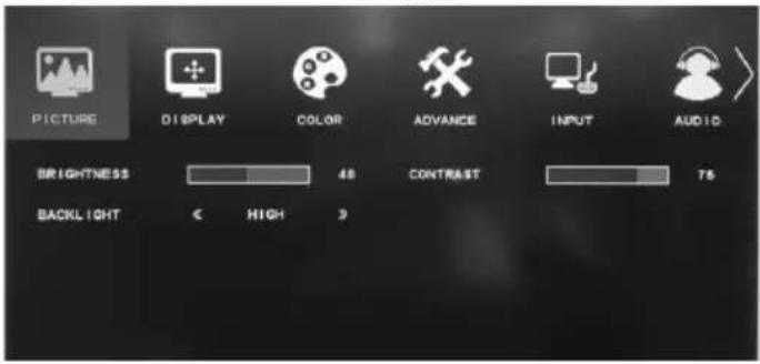
MAIN MENU 24
CHAPTER 7....24
CHAPTER 8....25
CHAPTER 9 25
SPECIFICATIONS......27
PRODUCT TECHNICAL DRAWING DETAILS.....29
OPS Connection Scheme....29
CHAPTER 10 ....30
Disposal of old Equipment and Batteries Only for European Union and countries with recycling systems.

The above mark is in compliance with the Waste Electrical and Electronic Equipment Directive 2012/19/EU (WEEE). The mark indicates the requirement NOT to dispose the equipment including any spent or discarded batteries as unsorted municipal waste, but use the return and collection systems available. If the batteries or accumulators included with this equipment display the chemical symbol Hg, Cd, or Pb, then it means that the battery has a heavy metal content of more than 0.0005% Mercury, or more than 0.002% Cadmium or more than, 0.004% Lead.

Note for the battery symbol (bottom symbol): This symbol might be used in combination with a chemical symbol. In this case it complies with the requirement set by the Directive for the chemical involved.
Important Safety Information

CAUTION
RISK OF ELECTRIC SHOCK DO NOT OPEN

CAUTION: TO REDUCE THE RISK OF ELECTRIC SHOCK DO NOT REMOVE COVER (OR BACK).
NO USER-SERVICEABLE PARTS INSIDE. REFER SERVICING TO QUALIFIED SERVICE PERSONNEL.
Please read these instructions carefully before use and keep for future reference
• This product is for indoor use only.
- Use this product at an altitude of less than 2000 meters above the sea level and in dry locations.
- Please keep that manual for further use.
- Unplug your product before starting to clean. Do not clean the product when it is on. Do not use liquid or aerosol cleaners. Use a damp cloth for cleaning. If that does not help, please use LCD display cleansers. Do not apply the cleaner directly on the product.
- To prevent breakdown, do not use non-advised accessories.
- Please do not place your product near wash basins, sinks, water pans, pools etc.
- Please leave 5 cm space between the product and walls or other furnitures.
- That product can only be started by the defined power source on its rating plate. For further information, please contact with your dealer.
- As a safety precaution, a three-wired grounding plug is given with the product. If you cannot plug the appliance, please apply your electrician to change the plug. As a safety precaution, please do not make any change on the grounding plug.
- Please provide the plug and socket to supply the needed power for appliance.
- Please place the product in a position that electric cables cannot be affected by the operations on the product.
- Follow all warnings and instructions marked on the product.
- To prevent the risk of fire or electric shock, please do not overuse the plugs and extension cords. Please do not open the lid of the monitor to service yourself. If the required service needs are not met by an authorized service, dangerous voltage and other risks may occur.
- If you will not use the product for a long period of time, unplug the power cord from the mains.
- Put the product on a well-ventilated place and prevent from bright light, overheat and damp.
- The product should be kept in 0 C° - 40 C°. Otherwise, the appliance may be damaged permanently.
- Plug the appliance to a grounded outlet. Always use the grounded power cord supplied with your product. Manufacturer is not responsible for any damage caused unearthed usage.
- The socket-outlet shall be installed near the equipment and shall be easily accessible.
- Do not stay in contact with the parts of the product that become hot for long periods of time. Doing so may result in low-temperature burns.
- The LCD panel used in this product is made of glass. Therefore, it can break when the product is dropped or applied with impact. Be careful not to be injured by broken glass pieces in case the LCD panel breaks.
- Usage of the monitor must not be accompanied by fatal risks or dangers that, could lead directly to death, personal injury, severe physical damage or other loss, including nuclear reaction control in nuclear facility, medical life support system, and missile launch control in a weapon system.
- Do not place any heat sources such as electric heaters, radiators, etc. near the product.
- In order to prevent a potential electrical shock, in extreme weather (storms, lightning) disconnect the product from the mains.
- Do not touch the controls other than those described in the operating instructions. Improper adjustment of controls not described in the instructions can cause damage, which often requires extensive adjustment work by a qualified technician.
- Do not shake the product. Ensure that it stays in a balanced stance on its position.
- Do not throw or drop any object on your product.
- Do not interfere on your products screen or any other surface with a sharp object.
- Do not keep your product in a humid environment.
- Do not keep your product in an extremely cold environment.
- Do not keep your product in an extremely hot environment.
Vent holes of the product
The vent holes are designed to provide the product to work constantly and prevent it from overheat. Do not block these openings in anyway. For the same reason, please do not place your product on beds, sofas, carpets and similar surfaces.
Never insert an object into the product through vents or openings. High voltage flows in the product, and inserting any objects in the vents or openings of the
product may cause electric shock, short circuit of the internal parts and/or fire. For the same reason, do not spill water or liquid on the product.
Repair
Unless a basic implementation on the product is specified by the producers' technical department on a document, do not repair your product by yourself. Otherwise, your guarantee may get suspended and you may risk your health or your product. In case of need, consult your authorized service.
- When the cable is worn off or harmed.
- If the product has been dropped or the cabinet has been damaged.
- If the performance of the product is changed or the appliance needs to be repaired.
- When a liquid was spilled on the product or when objects have fallen into the product.
- When the product has been exposed to rain or water.
- When the product does not operate properly as described in the operating instructions.
Replacement parts
In case the product needs replacement parts, make sure that the service person uses replacement parts specified by the manufacturer, or those with the same characteristics and performance as the original parts. Use of unauthorized parts can result in fire, electric shock and/or other danger.
Safety checks
Upon completion of service or repair work, request the service technician to perform safety checks to ensure that the product is in proper operating condition.
Wall mounting
When mounting the product on a wall, be sure to install the product according to the method recommended by the manufacturer.
Power Cord
- The power cord is used to disconnect the product from the mains and therefore it must remain readily operable.
- Use only the power cord supplied with the monitor.
- Do not damage the power cord nor place heavy objects on it, stretch it, over bend it or step on it. Also, do not add extension cords. Damage to the cord may result in fire or electric shock.
- When unplugging the appliance, always pull directly on the plug. Do not pull from the cable when unplugging the appliance.
- Do not use the power cord with a power tap. Adding an extension cord may lead to fire as a result overheating.
-
Do not remove or insert the power plug with wet hands. Doing so could result in electric shock.
-
Unplug the power cord if it is not used for a long time.
- Do not attempt to repair the power cord if it is broken or malfunctioning.
Especially for child safety
- Don't allow children to climb on or play with the monitor.
- Don't place the monitor on furniture that can easily be used as steps, such as a chest of drawers.
- Remember that children can become excited while watching a program, especially on a “larger than life” monitor. Care should be taken to place or install the monitor where it cannot be pushed, pulled over, or knocked down.
- Care should be taken to route all cords and cables connected to the monitor so that they cannot be pulled or grabbed by curious children.
Connections
Be sure to turn off the main power switch and disconnect the plug from the power outlet before connecting/disconnecting cables. Also, read the manual of the equipment to be connected.
Be careful not to confuse the input terminal with the output terminal when connecting cables. Accidentally reversing cables connected to the input and output terminals may cause malfunctions and other problems.
Wall Mounting
If a monitor is not positioned in a sufficiently stable location, it can be potentially hazardous due to falling. Many injuries, particularly to children, can be avoided by taking simple pre cautions such as:
- Using fixing devices like wall mount brackets recommended or supplied by the manufacturer.
- Only using furniture that can safely support the monitor.
- Ensuring the monitor is not overhanging the edge of the supporting furniture.
- Not placing the monitor on tall furniture (for example, cupboards or bookcases) without anchoring both the furniture and the monitor to a suitable support.
- Not standing the monitors on cloth or other materials placed between the monitor and supporting furniture.
• Educating children about the dangers of climbing on furniture to reach the monitor or its controls.
Transport and Shipping
- Your device must be kept in its original package to protect from damage to its accessories during transport and shipping.
of• Keep the product in normal position during transport.
- Do not drop the device during transport and protect it against impacts.
- Damages and faults that occur during transport after the delivery of the appliance to the customer are not included in the warranty cover.
- Product transportation, installation, repair and servicing must be done by qualified technical service personnel.
Intended Use
- Product should be used for household and similar general use but which may also be used in places of public assembly such as schools, offices, theatres, places of worship.
- Product is only suitable for connecting commercial mains socket outlets. Do not connect product industrial socket outlets.
Foreseeable misuse and incorrect use
- For apparatus intended to be used in vehicles, ships or aircraft or at altitudes exceeding 2000m above sea level, for outdoor use or in general for the application other than mentioned in user manual additional requirements may be necessary.

CAUTION

Do not leave a static image displayed for prolonged period of time. If a static image is displayed continuously for a long period of time, that image may cause image sticking on the display. This condition is not permanent, but may require a considerable amount of operational display time to dissipate, depending upon the degree of image stick. 120 minutes of continuous motion display will eliminate most image sticking effects at normal room temperature (not lower than 10 C). As the nature of the TFT technology, you may see some amount of bright, dark, red, green and blue dots and sparklings on the screen, those do not affect the performance of the computer and are not accepted as a defect.

Warning
This is a class A. In a domestic environment this may cause radio interference in which case the user may be required to take adequate measures.
BATTERY SAFETY GUIDELINES
Used correctly, domestic batteries are a safe and dependable source of portable power. Problems can occur if they are misused or abused resulting in leakage or, in extreme cases, fire or explosion.
Here are some simple guidelines to safe battery use designed to eliminate any such problems.
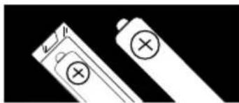
• Take care to fit your batteries correctly, observing the plus and minus marks on the battery and appliance.
Incorrect fitting can cause leakage or, in extreme cases, fire or even an explosion.
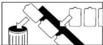
- Replace the whole set of batteries at one time, taking care not to mix old and new batteries or batteries of different types, since this can result in leakage or, in extreme cases, fire or even an explosion.
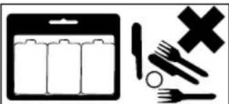
- Store unused batteries in their packaging and away from metal objects which may cause a short-circuit resulting in leakage or, in extreme cases, fire or even an explosion.
- Remove dead batteries from equipment and all batteries from equipment you know you are not going to use for a long time. Otherwise the batteries may leak and cause damage.
- Never dispose of batteries in fire as this can cause them to explode. Please recycle dead batteries; do not put with the normal household waste.
- Never attempt to recharge ordinary batteries, either in a charger or by applying heat to them. They may leak, cause fire or even explode. There are special rechargeable batteries which are clearly marked as such.
- Supervise children if they are replacing batteries themselves in order to ensure these guidelines are followed.
- Remember that small button cell batteries such as used in some hearing aids, toys, games and other appliances, are easily swallowed by young children and this can be dangerous.
- Keep loose button cells away from young children.
- Make sure battery compartments are secure.
- Seek medical advice if you believe a cell has been swallowed.
- If leaked battery fluid gets on your skin or clothing, rinse immediately and thoroughly. If it gets into your eye, bathe your eye well rather than rubbing and seek medical treatment immediately. Leaked battery fluid that gets into your eye or your clothing may cause a skin irritation or damage your eye.
CAUTION
RISK OF EXPLOSION IF BATTERY IS REPLACED BY AN INCORRECT TYPE. DISPOSE OF USED BATTERIES ACCORDING TO THE INSTRUCTIONS.
Any issues which are caused by customer mis-adjustment of any software including the operating system are not covered by the warranty.
Depending on the model you buy, the actual appearance of the product may differ from the images used in this manual.
Introduction
This instruction manual is intended to help you operate your "INTERACTIVE BOARD" product in a proper way and get a better performance.
Chapter 1. Introducing "INTERACTIVE BOARD"
Chapter 2. Using "INTERACTIVE BOARD". Instructions for using the product and its functions
Chapter 3. Usage of the Touch Screen
Chapter 4. Connecting other equipment to "INTER ACTIVE BOARD" and sound
Chapter 5. Usage of Starboard Software
Chapter 6. Power of the "INTERACTIVE BOARD"
Chapter 7. Using your "INTERACTIVE BOARD" product more efficiently
Chapter 8. Troubleshooting
CHAPTER 1
INTRODUCING THE "INTERACTIVE BOARD"
Congratulations for buying our the 84"(213cm) INTERACTIVE BOARD product!
The “INTERACTIVE BOARD” combines the 84"(213cm) LED monitor and touch-screen features and offers a modern design that can be easily adapted to all working conditions.
All components of INTERACTIVE BOARD product are designed to be user friendly. Besides having a compact design, this product supports several functional features. Touch screen and high definition speakers are two of these features.
"INTERACTIVE BOARD" has a powerful information processing system.
Note: The information here should only be used as a reference, the definitions or images in this manual may be different from your "INTERACTIVE BOARD".
Display:

natural_image
Blank gray rectangular image with no visible text, symbols, or markingsDepending on the model, the product image may be different from the product you buy.
CHAPTER 2:
INFORMATION ABOUT USAGE OF "INTERACTIVE BOARD" and ITS FUNCTIONS Turning on and off your "INTERACTIVE BOARD"
- Turning on the system
After ensuring that the "INTERACTIVE BOARD" is plugged in, press the power switch button near power plug cable.
- Turning off the "INTERACTIVE BOARD"
"When you complete your work or want to have a break, you can turn the "INTERACTIVE BOARD" off.
| Situation Method | What is required to continue | |
| Turning off the system completely | In order to prevent data loss, please turn off your system by following the procedure in your operating system. In case your system does not respond to the procedural shut down because of resource conflicts, you can turn off your “INTERACTIVE BOARD” by holding down the power button for 4 seconds. Keep in mind that your unsaved data will be lost in this situation. | Pressing the power button |
▲ Important!
To avoid any issue - please shut down fully via the built in PC operating system. Unplugging the power directly should be avoided and may cause permanent breakdown. When a permanent breakdown is detected in the system, the appliance should be turned to factory settings by applying the steps in Recovery Chapter.
Panel:
| Panel type | TFT 84"(213cm) UHD 2D LCD | |
| Resolution | 3840 x 2160 | |
| Visual angle | Horizontal | 178° |
| Perpendicular | 178° | |
| Max. brightness | 350 cd/m2 | |
| Max. contrast | 1400:1 | |
| Response time | 5 ms G2G | |
| H-Frequency | 244KHz ~ 280 KHz (nomial: 270Hz) | |
| V-Frequency | 95Hz ~ 104Hz (nominal: 100Hz) | |
RS232 Command Table - Baud rate 192000
| Function Name | Function Type | Command Data(HEX) Additional Information | |||||||||
| OPS Power | OFF BE EF 03 | 06 00 2 | A D3 | 01 00 | 00 60 00 | 00 | |||||
| ON BE EF 03 | 06 00 BA | D2 | 01 00 | 00 60 01 | 00 | ||||||
| GET BE EF 03 | 06 00 19 | D3 | 02 00 | 00 60 00 | 00 1D | 00 00: | OFF 1D | 00 01: ON | |||
| Source | OPS BE EF 03 | 06 00 FE | D2 | 01 00 | 00 20 00 | 00 | |||||
| HDMI - 2 BE EF | 03 06 | 00 0E | D2 01 | 00 00 2 | 00 03 00 | ||||||
| HDMI - 1 BE EF | 03 06 | 00 0E | D2 01 | 00 00 2 | 00 04 00 | ||||||
| VGA BE EF 03 | 06 00 6 | E D2 | 01 00 | 00 20 01 | 1 00 | ||||||
| GET BE EF 03 | 06 00 CD | D2 | 02 00 | 00 20 00 | 00 1D | 00 01: | PC | 1D 00 02: HDMI-21D 00 03: HDMI-1 | 1D 0004:VGA | ||
| Backlight | GET BE EF 03 | 06 00 8 | D2 | 02 00 | 03 20 00 | 00 1D | 00 XX: | value | |||
| INCREMENT | BE EF 03 | 06 | 00 EF | D2 04 00 | 03 20 00 | 00 00 | |||||
| DECREMENT | BE EF 03 | 06 | 00 3E | D3 05 00 | 03 20 | 00 00 | |||||
| SET | BE EF | 03 | 06 00 | 89 D2 | 03 00 | 03 20 | 01 XX | default value: 0x64 | range: 0x64-0x1E | ||
| RESET | BE EF | 03 06 | 00 58 | D3 06 00 | 00 70 | 00 00 | |||||
| Volume | GET BE EF 03 | 06 00 31 | D3 | 02 00 | 01 20 00 | 00 1D | 00 XX: | value | |||
| INCREMENT | BE EF | 03 | 06 00 57 | D3 04 | 00 01 2 | 00 00 | |||||
| DECREMENT | BE EF 03 | 06 | 00 86 | D2 05 00 | 01 20 | 00 00 | |||||
| SET | BE EF | 03 | 06 00 | 31 D3 | 03 00 | 01 20 | 01 XX | default value: 0x10 | range: 0x1D-0x00 | ||
| Screen | OFF BE EF 03 | 06 00 FB | D8 | 01 00 | 20 30 00 | 00 | |||||
| ON BE EF 03 | 06 00 6B | D9 | 01 00 2 | 20 30 01 | 00 | ||||||
| GET BE EF 03 | 06 00 G8 | D8 | 02 00 | 20 30 00 | 00 1D | 00 00: | OFF 1D | 00 01: ON | |||
| Auto Adjust | ON BE EF 03 | 06 00 32 | D4 | 01 00 19 | 20 01 00 | only VGA | |||||
| OFF BE EF 03 | 06 00 A2 | D5 | 01 00 | 19 20 00 | 00 | only VGA | |||||
| Keypad Lock | ON BE EF 03 | 06 00 93 | 97 | 01 00 | 11 24 01 | 00 | |||||
| OFF BE EF 03 | 06 00 03 | 96 | 01 00 | 11 24 00 | 00 00 | ||||||
| GET BE EF 03 | 06 00 3 | 96 | 02 00 | 11 24 00 | 00 00 1 | 00 00 | OFF 1D | 00 01: ON | |||
| Remote Controller Lock | OFF BE EF 03 | 06 00 E7 | 96 | 01 00 | 16 24 01 | 00 | |||||
| ON BE EF 03 | 06 00 77 | 97 | 01 00 | 16 24 00 | 00 | ||||||
| GET BE EF 03 | 06 00 44 | 97 | 02 00 | 16 24 00 | 00 00 1 | 00 00 | OFF 1D | 00 01: ON | |||
| OSD Menu | ON BE EF 03 | 06 00 6A | 63 | 01 00 | 00 37 01 | 00 | |||||
| OFF | BE EF | 03 | 06 00 | FA 62 | 01 00 | 00 37 | 00 00 | ||||
| Contrast | GET BE EF 03 | 06 00 FD | D3 | 02 00 | 04 20 00 | 00 00 1 | 00 XX: | value | |||
| SET | BE EF | 03 | 06 00 | FD D3 | 03 00 | 04 20 | 01 XX | range: 0xB2-0x4E | |||
| INCREMENT | BE EF | 03 | 06 00 9B | D3 04 | 00 04 2 | 00 00 00 | |||||
| DECREMENT | BE EF 03 | 06 | 00 4A | D2 05 00 | 04 20 | 00 00 | |||||
| Monitor | ON BE EF 03 | 06 00 19 | D3 | 02 00 00 | 60 02 00 | ||||||
| OFF BE EF 03 | 06 00 19 | D3 | 02 00 | 00 60 01 | 00 | ||||||
| GET BE EF 03 | 06 00 19 | D8 | 03 00 | 00 60 07 | 00 1D | 00 00: | OFF 1D | 00 01: ON | |||
| Mute | ON BE EF 03 | 06 00 D6 | D2 | 01 00 C2 | 20 01 00 | ||||||
| OFF BE EF 03 | 06 00 46 | D3 | 01 00 | D2 20 00 | 00 | ||||||
| GET BE EF 03 | 06 00 75 | D3 | 02 00 | D2 20 00 | 00 1D | 00 00: | OFF 1D | 00 01: ON | |||
| Auto Position | EXECUTE | BE EF | 03 | 06 00 | 91 D0 | 06 00 | 0A 20 | 00 00 | only VGA | ||
| Color Temperature | INCREMENT | BE EF | 03 | 06 00 | OB F5 | 10 00 | B0 30 | 03 00 | 9300K, 6500K,5000K, 7500K, USER | ||
| DECREMENT | BE EF 03 | 06 | 00 CB | F8 01 00 | B0 30 | 13 00 | 9300K, 6500K,5000K, 7500K, USER | ||||
| GET BE EF 03 | 06 00 C8 | F5 | 02 00 | B0 30 00 | 00 1D | 00 XX: | value | 00=9300K,01=6500K,02=5000K,03=7500K, 04=USER | |||
| Clock | INCREMENT BE EF 03 06 00 19 D 4 03 00 00 60 03 00 only VGA | ||
| DECREMENT BE EF 03 06 00 19 D 5 03 00 00 60 04 00 only VGA | |||
| GET BE EF 03 06 00 19 D 7 03 00 00 60 06 00 1D XX XX: value only VGA | |||
| Phase | INCREMENT BE EF 03 06 00 2F 8 3 04 00 03 21 00 00 only VGA | ||
| DECREMENT BE EF 03 06 00 FE 8 2 05 00 03 21 00 00 only VGA | |||
| GET BE EF 03 06 00 49 83 02 00 03 21 00 00 1D XX: value only VGA | |||
| H-Position | INCREMENT BE EF 03 06 00 97 8 2 04 00 01 21 00 00 only VGA | ||
| DECREMENT BE EF 03 06 00 46 8 3 05 00 01 21 00 00 only VGA | |||
| GET BE EF 03 06 00 F 1 82 02 00 01 21 00 00 1D XX XX: value only VGA | |||
| V-Position | INCREMENT BE EF 03 06 00 6B 8 3 04 00 00 21 00 00 only VGA | ||
| DECREMENT BE EF 03 06 00 BA 8 2 05 00 00 21 00 00 only VGA | |||
| GET BE EF 03 06 00 0D 83 02 00 00 21 00 00 1D XX: value only VGA | |||
| Color Temp Gain R | INCREMENT BE EF 03 06 00 52 F 4 04 00 B1 30 00 00 | ||
| DECREMENT BE EF 03 06 00 83 F 5 05 00 B1 30 00 00 | |||
| GET BE EF 03 06 00 34 F 4 02 00 B1 30 00 00 1D XX: value | |||
| Color Temp Gain G | INCREMENT BE EF 03 06 00 16 F 4 04 00 B2 30 00 00 | ||
| DECREMENT BE EF 03 06 00 C7 F 5 05 00 B2 30 00 00 | |||
| GET BE EF 03 06 00 70 F 4 02 00 B2 30 00 00 1D XX: value | |||
| Color Temp Gain B | INCREMENT BE EF 03 06 00 EA F 5 04 00 B3 30 00 00 | ||
| DECREMENT BE EF 03 06 00 3B F 4 05 00 B3 30 00 00 | |||
| GET BE EF 03 06 00 8C F 5 02 00 B3 30 00 00 1D XX: value | |||
| Screen Freeze | On BE EF 03 06 00 19 D3 02 00 00 60 03 00 | ||
| Off BE EF 03 06 00 19 D3 02 00 00 60 03 01 |
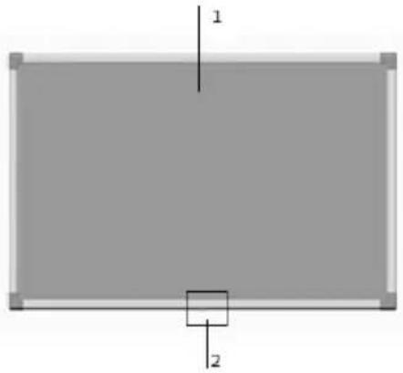
Part Names
Front View
natural_image
Simple diagram of a rectangle with labeled dimensions (1 and 2) and a small square at the bottom center (no text or symbols beyond labels)- LCD Panel
- Remote Control Sensor
Rear View
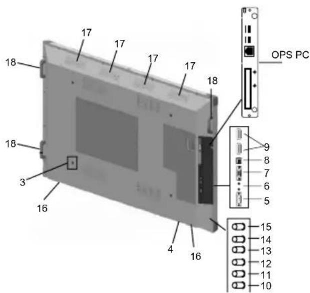
- Hanger Point
- AC Input Terminal
- RS-232 Input Terminal
- Line In & Line Out Terminals
- VGA Input Terminal
- B-Type USB Input Terminal
- HDMI Input Terminal x 2
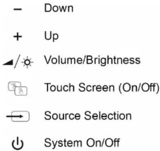
- Power Button
- Source Select Button
- Touch Screen (On/Off) Button
- Volume/Brightness Button
- Up Button
- Down Button
- Speakers
- Vents
- Handle
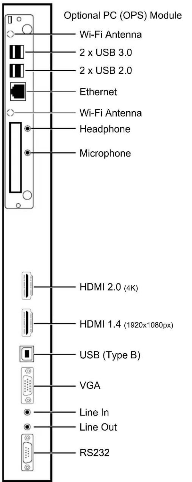
OPS (Open Pluggable Specification) PC- Optional
Tips
- OPS is an optional plug&play PC. It may be based on intel or ARM based PC.
- DS (Digital Signage) monitor is complying with both intel ARM based OPS PC.
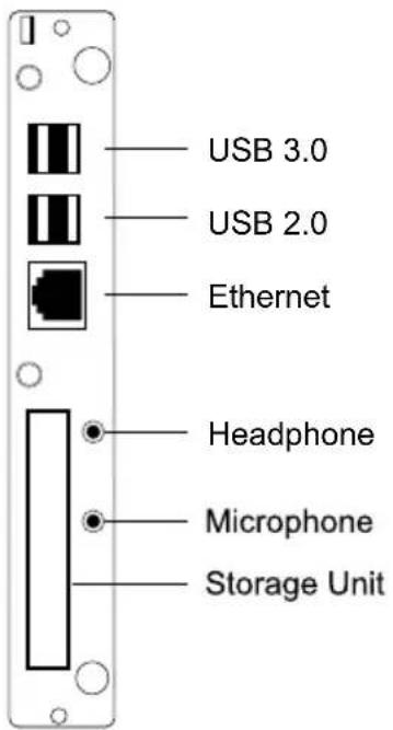
USB 3.0 Ports
- Use a commercially available USB cable to bidirectional transfer data.
USB 2.0 Ports (Optional)
- Use a commercially available USB cable to bidirectional transfer data.
Lan Terminal
- Use commercially available Ethernet cable to connect Local Area Network.
Microphone and Headphone terminals
- Use headphone terminal to listen the stereo sound files.
- Use Microphone terminal to record the sounds.
Storage Unit
• Use HDD Storage Unit (500 GB)
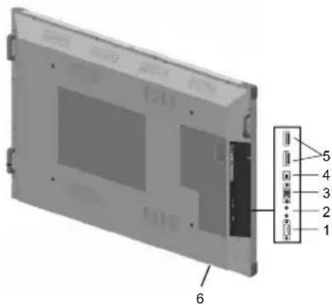
CONNECTING PERIPHERAL EQUIPMENT
Caution!
- Be sure to disconnect the plug from the power outlet before connecting/disconnecting cables. Also, read the manual of the equipment to be connected.
- Be careful not to confuse the input terminal with the output terminal when connecting cables. Accidentally reversing cables connected to the input and output terminals may cause malfunctions and the other problems.
- Do not use any cable that has a damaged or deformed terminal. Using such cables may cause malfunctions.
Tips
- Wait product to search and find the source automatically when the product is used for the first time. The screen is adjusted automatically.
1. AC Input Terminal
- Use only the power cord supplied with the product.
2. RS-232 Input Terminal
- You can control the product from a PC by connecting a commercially available RS-232 straight cable between these terminals and the PC.
3. Line In/Out Terminals
- Use an audio cable without resistance for Line In and Line Out terminals.
• Line In: Connect an external audio device to record or manipulate the incoming sound data.
• Line Out: Connect external speakers (Surround System).
7. VGA Input Terminal
- Use a commercially available VGA cable
- Use Source Select button (11 Source Select Button) to set mode as a VGA.
8. USB B-Type Input Terminal
- Use USB B-Type connector for the external PC and touch screen connection.
9. HDMI input terminal x 2
- Use a commercially available HDMI cable (conforming to the HDMI standard).
- Use Source Select button (11 Source Select Button) to set mode as an HDMI.
- The length of the signal cables or surrounding environment may affect the image quality.
Tips
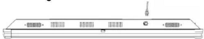
Connecting The Power Cord
natural_image
Line drawing of a rectangular electronic device with ventilation slots and a connector (no text or symbols)Caution!
- Use only the power cord supplied with the product.
- Plug the power cord (supplied) into the AC input terminal.
Press the power button (button " 🔊" on device or power button on Remote controller) to turn the power ON/OFF.
- When use POWER button to turn product off and back on, always wait for power LED is ON. Product can be turned back on safely after seeing power LED is ON.
A short interval may result in a malfunction.
- For a complete electrical disconnection, pull out the main power plug.
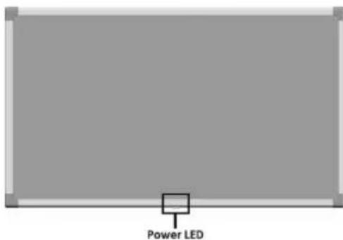
| Status of LED Status of the Monitor&PC | |
| ON Power Off / Standby mode | |
| OFF On | |
Tips
• After turning the product off, it will automatically enter standby mode approximately 60 sec. later.
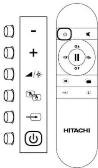
BASIC OPERATION
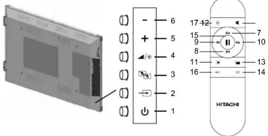
1-17. ON/OFF
2-16. Source Select (Input mode selection)
- You can select the input source by pressing the input switch of the product.
Tips
- The input mode is automatically changed to mode which is actively used by an external source.
3. Touch Screen (On/Off) Button
- Turns on/off the touch screen.
4. Volume/Brightness Button
- You can select the Volume or Brightness by pressing the Volume/Brightness switch of the product.
5-6. Up/Down +/- (Volume/Brightness adjustment)
- Pressing Up(+) or Down(-) buttons display the VOLUME or BRIGHT menu.
Use these buttons to adjust the volume of the sound or adjust the brightness.
If you do not press any buttons for about 3 seconds, the VOLUME or BRIGHT menu automatically disappears.
7-8. Brightness +/- (Brightness adjustment)
- Pressing Brightness Up(+) or Brightness Down(-) buttons display the BRIGHT menu.
- Display On/Off button only turns on/off the monitor so system will not enter standby mode.
Use these buttons to adjust the brightness.
If you do not press any buttons for about 3 seconds, the BRIGHT menu automatically disappears.
9-10. Vol +/- (Volume adjustment)
- Pressing Volume Up(+) or Volume Down(-) buttons display the VOLUME menu.
Use these buttons to adjust the volume of the sound. If you do not press any buttons for about 3 seconds, the VOLUME menu automatically disappears.
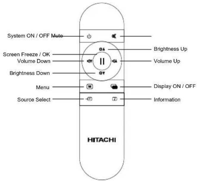
11. Menu
- Turns On/Off the touch screen.
12. Mute
• Turns off the volume temporarily.
- Press the MUTE button again to turn the sound back to the previous level.
13. Display On/Off
- Turns on/off the monitor.
14. Information
- Displays the mode which is displayed by monitor at that time.
Tips
However, System On/Off turns on/off the system so system will enter standby mode.
Warning!
- Remote Control may not work properly if there would be any object under the product closer than 100cm.
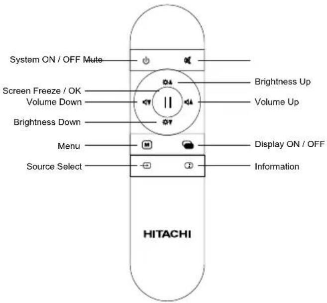
Function Buttons and Remote Control
"INTERACTIVE BOARD" has 6 function buttons. These buttons and the remote control are as following:
Remote Control
Replacing the Batteries
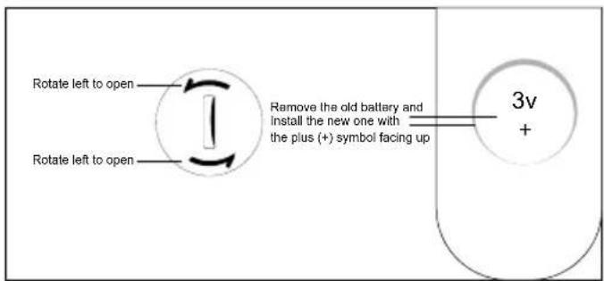
Remove the back cover to reveal the battery compartment and make sure the batteries are inserted the right way round. Suitable battery types for this remote are CR2025.
Remove exhausted batteries immediately to prevent acid from leaking into the battery compartment.
▲ Important!
The empty batteries should be replaced with the equivalent new batteries.
CAUTION : Risk of explosion if battery is replaced by an incorrect type. Dispose of used batteries according to the instructions. Batteries must not be exposed to excessive heat such as sunshine, fire or the like.
Remote Control Operating Area
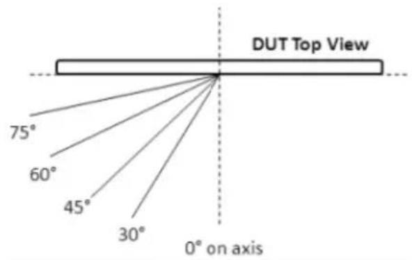
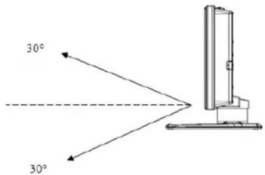
| RC: CT-8047 | |
| 0° on axis 12m | |
| Left 30° | 8m |
| Right 30° 8m | |
| Left 45° 5m | |
| Right 45° 5m | |
| Left 60° | 5m |
| Right 60° 5m | |
| Up 30° 5m | |
| Down 30° 5m | |
Definition of Source Transition
Definition of Source Transition by Button Chart
Press the source “-” button to reach the source selection menu by button chart. The source menu will be displayed as below. The desired mode can be selected by pressing Right-Left buttons on IR or Keypad.
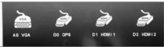
Source Switching with remote control Description
Source menu can be reached by the source button on the remote control. The chosen source can be displayed by pressing "Source Select" Button on Remote Controller.
If the chosen source has no signal, a warning will be displayed as below.
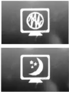
natural_image
Two computer monitors displaying icons: one with a globe and star, the other with a crescent moon and stars (no text or symbols)OSD Menu can be reached by pressing "Menu" Button on Remote Controller or Keypad.
Battery Safety Guidelines
CAUTION : Risk of explosion if battery is replaced by an incorrect type. Dispose of used batteries according to the instructions.

natural_image
Line drawings of various electronic components including batteries, cylinders, and connectors (no text or symbols)BATTERY SAFETY GUIDELINES
Used correctly, domestic batteries are a safe and dependable source of portable power. Problems can occur if they are misused or abused resulting in leakage or, in extreme cases, fire or explosion.
Here are some simple guidelines to safe battery use designed to eliminate any such problems.
natural_image
Two battery cells with one showing a positive charge symbol (no text or labels)Take care to fit your batteries correctly, observing the plus and minus marks on the battery and appliance. Incorrect fitting can cause leakage or, in extreme cases, fire or even explosion.
natural_image
Diagram showing battery arrangement with arrows indicating direction (no text or symbols)Replace the whole set of batteries at one time, taking care not to mix old and new batteries or batteries of different types, since this can result in leakage or, in extreme cases, fire on even an explosion.
natural_image
Simple black-and-white icon set showing a refrigerator with food containers and a crossed-out fork (no text or symbols)Store unused batteries in their packaging and away from metal objects which may cause a short-circuit resulting in leakage or, in extreme cases, fire or even an explosion.

natural_image
Abstract white line drawing on black background with no text or symbolsRemove dead batteries from equipment and all batteries from equipment you know you are not going to use for a long time. Otherwise the batteries may leak and cause damage.
Never dispose of batteries in fire as this can cause them to explode. Please recycle dead batteries; do not put with the normal household waste.

natural_image
Pure electrical circuit lines without any symbolsNever attempt to recharge ordinary batteries, either in a charger or by applying heat to them. They may leak, cause fire or even explode. There are special rechargeable batteries which are clearly marked as such.

natural_image
Illustration of a hand holding a device (no text or symbols visible)Supervise children if they are replacing batteries themselves in order to ensure these guidelines are followed.

natural_image
Black-and-white illustration of a human mouth with a pill and a cross mark (no text or symbols)Remember that small button cell batteries such as used in some hearing aids, toys, games and other appliances, are easily swallowed by young children and this can be dangerous.

natural_image
Abstract black-and-white graphic with white hand gestures and curved lines (no text or symbols)Keep loose button cells away from young children.

natural_image
Illustration of a hand pressing down on a small electronic component (no text or symbols visible)Make sure battery compartments are secure.

natural_image
Silhouette of a human torso with a downward arrow and a cross symbol (no text or labels)Seek medical advice if you believe a cell has been swallowed.
CHAPTER 3
Touch screen
84"(213cm) touch screen with the feature of multi-spot touch (10 spot at the same time) and infrared technology.
Using the Touch Screen with External Source
Touch screen is integrated with with optional embedded computer module. IF you want to use the touch screen when an external source is connected via HDMI or VGA, please connect the external source to "INTERACTIVE BOARD" via a USB to USB cable. Connect that cable to the USB B input. Touch screen will be active in a short time. "To use the touch screen by an external source may require a driver. In this case, the chosen required touch screen drive should be loaded to external source device from the CD given with that device."
Touch screen controls the currently displayed image on the screen. If “Embedded Computer” is being used as source, touch screen controls the “Embedded Computer”. If an external source is connected via HDMI or VGA and chosen as the source then that source is automatically selected.
WARNING: To activate the touch screen feature of the Interactive Board, the processing system should be started.
WARNING: If any drivers are missing or you require technical support - please contact pj.support@hitachi-eu.com.
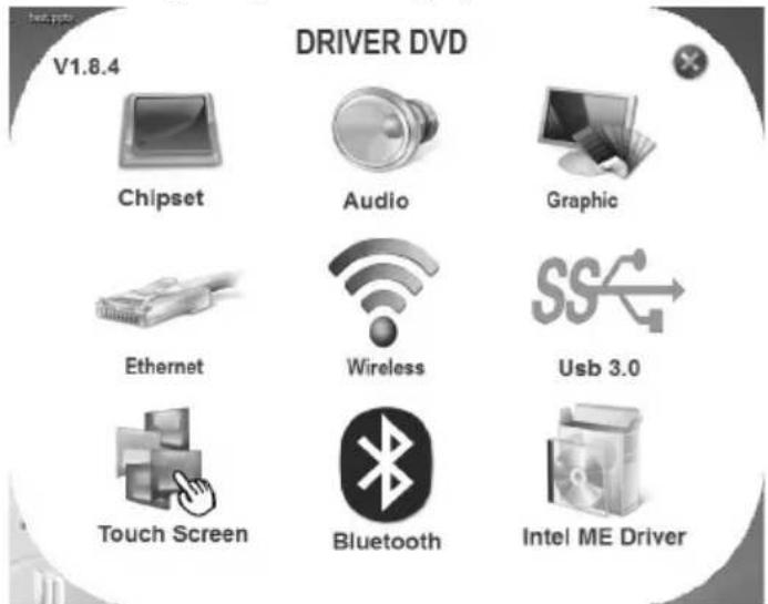
Touch Screen Installation
3.1.1. About installation
-
Before starting installation, ensure that all drivers are installed correctly and USB are installed correctly. The usage of standard drivers given by manufacturers is recommended.
-
The multi-spot touch screen should be connected before installation.
-
Close the antivirus programme and Trojan preventing programme before installation (as 360 antivirus and 260 safeguard).
-
If the used driver has been installed in the computer before, please unload the installation completely and, if needed, delete the old installation files.
-
Standard USB extension cord should be used as USB connector cable.
-
If you use Windows XP processing system, you should first install Microsoft.net Framework 2.0.
-
After the VGA and HDMI connections of the screen and server connections are unplugged and plugged again, the USB connection of touch screen should
also be unplugged and plugged again. Otherwise, touch system will not function properly.
- After the USB connection is ready, the driver will be loaded automatically and the touch screen will be ready to use.
Function Description
-
The coordinates of the touch panel and display screen should be accurately matched by calibration.
-
When will calibration be needed?
a) The first time you have installed touch panel bundled software.
b) Inconsistency occurred between the mouse and your finger action.
c) After changing the touch panel or monitor.
d) Having moved the touch panel or there is a change in monitor resolution.
Operating steps
- Click "Calibration" on Touch Service main interface
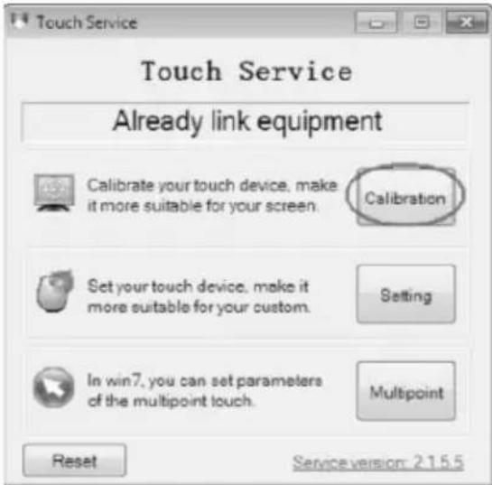
- Touch the center of the calibration points shown on the screen one by one with your finger in order
below (Figure 4-6). In total, there are four calibration points. (Upper left corner→ upper right corner
→ lower right corner → lower left corner).
a) The number in the center is the countdown. When it comes to zero, you will automatically
exit the calibration without saving the result.
b) Also, you can press ESC to exit the calibration process without saving the result.

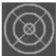
Touch the centre of the calibration point.
- Having touched the four calibration points, a dialogue box will pop up. Click "Yes" to save the calibration data and "No" not to. If you don't click yes or no within 10s, you will automatically exit the calibration process without saving the data.

Connections Diagram
Depending on the model, the product image may be different from the product you buy.
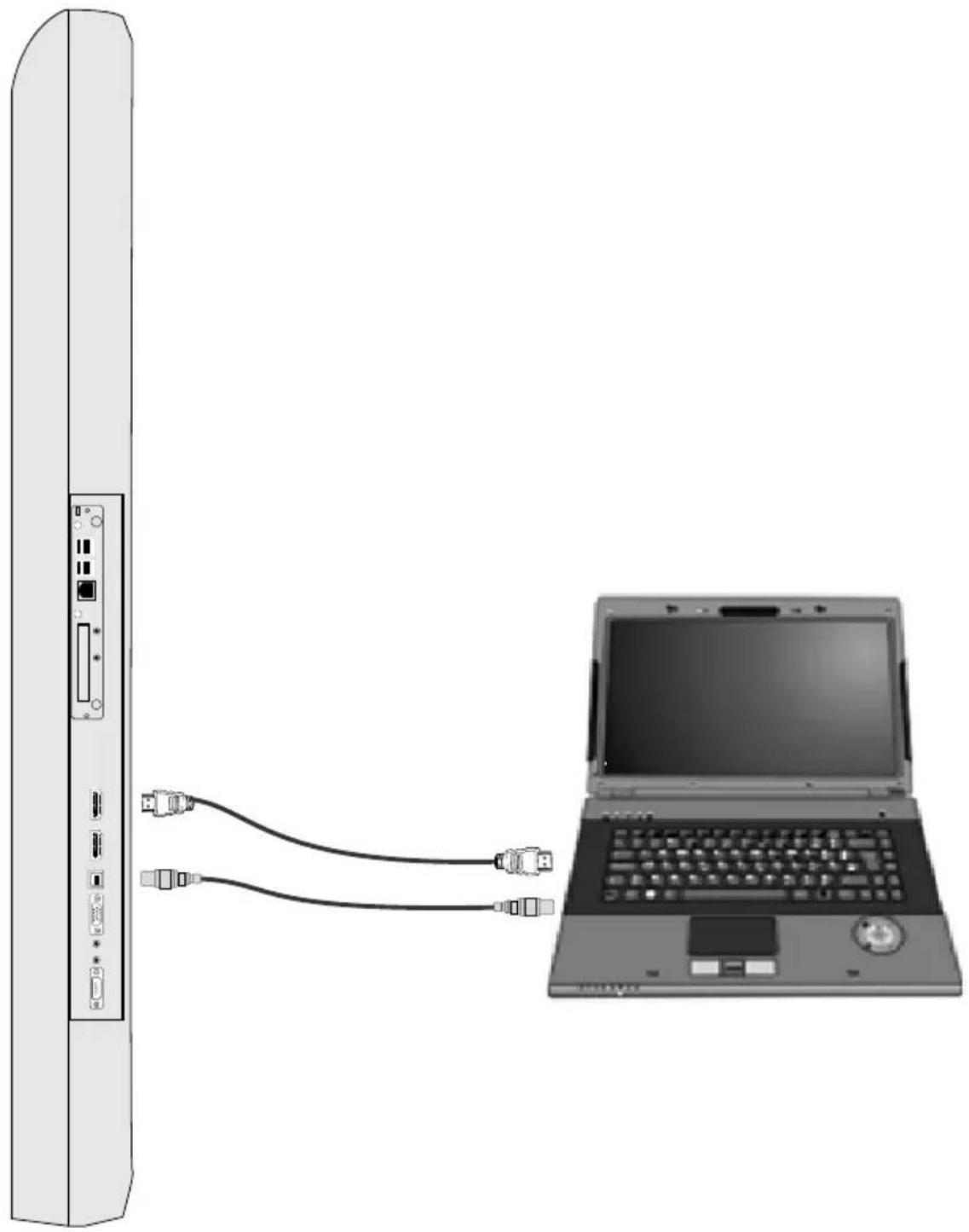
natural_image
Diagram showing a laptop connected to a server via two USB cables (no text or symbols present)Image transfer by an external source via HDMI
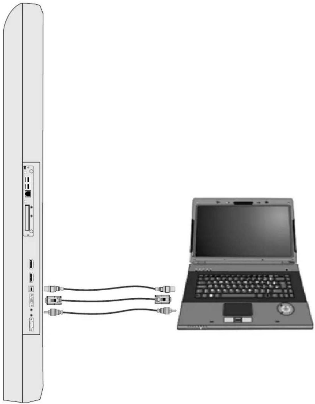
natural_image
Diagram showing a server connected to a laptop via cable, no text or symbols presentImage transfer by an external source via VGA
▲Important!
To transfer image and audio transfer via VGA at the same time, except for the VGA cable, an audio transfer cable should be also used as shown (3.5 mm stereo).
CHAPTER 4
CONNECTION OF OTHER DEVICES ON "INTERACTIVE BOARD" AND SOUND You can increase the efficiency of your device, you can connect other peripheral devices on the "INTERACTIVE BOARD". Please read the instruction manuals of these peripheral units provided by their manufacturers while using them. In this section, installation of the following devices is described:
- USB Devices
Connecting the USB devices
- "INTERACTIVE BOARD" has 2 USB2.0 and 2 UB3.0 input for USB devices as keyboard, mouse, printer, scanner, digital camera, etc.
- USB (Universal Serial Bus) is developed for industrial standard computers. It supports Pnp (Plug and Play) technology; so you do not need to close “INTERACTIVE BOARD” while connecting or disconnecting the USB devices.
Updating of internal devices
If you want to change the temporary memory (RAM) module on your "INTERACTIVE BOARD", to prevent a potential malfunction in computer, please contact with technical department for details. Please do not change any parts without getting help from a professional.
These transactions should be realized by service centre.
Usage of External Sources with Interactive Board (HDMI-VGA)
When you want to use the external sources with Interactive Board, please ensure that the connections are made as defined in the manual.
- Plug the cable of the desired external device (HDMI1 – HDMI2 – VGA).
- Plug the USB cable transferring the touch screen feature to external source.
Note: To connect via VGA, do not forget to plug the external source cable transferring the audio function of source to the Interactive Board.
Please be sure that you have transferred the image of the external source to Interactive Board.
In settings of the screen features of your external source, in the section about displaying options;
There are double image (displaying the external source image on both Interactive Board and external source) and single image options. (Displaying on only external device or Interactive Board)
Choose the Internal Board as single display device via the screen features of the connected external source. Displaying the transferred image on only Interactive Board will provide you the best solution.
To use external source, to plug the Interactive Board is enough. You can use external sources without connecting the Embedded PC. Your device will detect the transferred external source automatically.
If you connect the external source to Interactive Board while the Embedded PC is active, your device will not detect the external source automatically.
To pass to external source, press the source selection button shown as “→”.
Mic and Audio in "INTERACTIVE BOARD"
▲ Important!
Before using the mic function of "INTERACTIVE BOARD", please be sure that mic driver given with the device is installed. In case of any sound distortions during recording, please decrease microphone volume.
The mic function of the "INTERACTIVE BOARD" includes below:
- Digital audio and analogue mixer support
- Realtek High Definition sound codec support
- Sound control via function buttons
The methods of playing and recording sound depend on the operating system in use. Please refer to the instructions in your operating systems support points for these methods.
CHAPTER 5
Processing System
Windows 10
Drivers
The drivers in that CD are updated drivers providing your device to function properly. Copies of drivers in the CD are also in D index of your device. You can get the updated drivers from the Service Centre. You should install the drivers of your processing system.
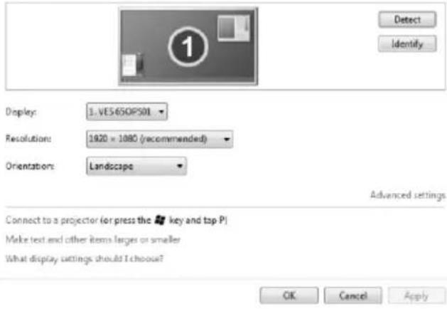
Screen Resolution of "INTERACTIVE BOARD"
Screen resolution of "INTERACTIVE BOARD" is adjusted in two ways.
- Via operating system;
Click right on your mouse and choose screen resolution.
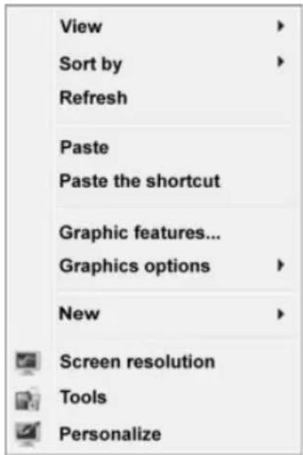
Change the appearance of your display
• Via the screen chart display panel;
Intel® HD Graphics Control Panel


Customize your graphics settings for an enhanced visual experience.
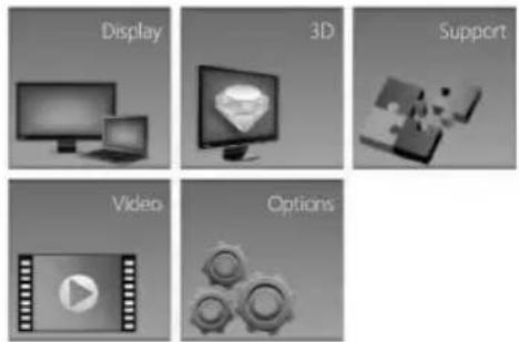
▲ Important!
If the resolution will be adjusted via the control panel, the "Scaling" tab should be selected as "Save Screen Scaling". The calibration of your touch screen will be distorted if that option is not selected.

Network Connection (Optional Pc Unit)
Using the Network Connection Option
Your "INTERACTIVE BOARD" product has a 10/100/1000 Lan module and it connects "INTERACTIVE BOARD" to other computers on the network. It supports a data transfer rate up 10/100/1000 Mbps. The integrated network module is accompanied by a RJ-45 connector.

Wireless Network Connection
Wireless network connection, which enables users to connect wireless networks, provides great convenience for data transfer. Be sure that chipset driver software is installed. Install the relevant device driver.
Processing system
Selections and language may vary with respect to the region of sale. Hardware and software support may vary with respect to the installed operating system. System instabilities and incompatibilities arising from operating systems are not warranted.
Note: Any customer related problem in the processing system is not included in warranty.
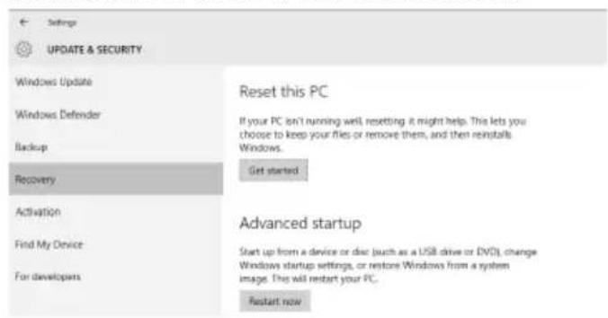
Windows 10 System Recovery
- At the desktop, click the Search the web and Windows box and type "reset".
- Select Reset this PC (System settings).
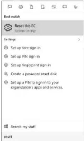
- Under Reset this PC, select Get started.
- Select the option Keep my files.
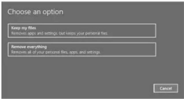
- Note any apps or drivers that will need to be reinstalled after the refresh has completed.
- Follow the on-screen instructions to complete the refresh process. This will take some time and your computer will restart.
CHAPTER 6:
SYSTEM BIOS INFORMATION USING BIOS ACTIVELY (Optional PC Unit)
Using BIOS actively
This section explains points on the integrated software of your Interactive Monitor. This BIOS (Basic Input Output System) software cluster, critical for your device, is stored on a chip on the mainboard. With this software, your hardware shall be matched with the selected operating system and the system shall be prepared in coordination. BIOS includes both POST (Power On Self Test) and Aptio Installation Software sections. POST provides methods for system control during system restart and SCU provides configuration of your Interactive Monitor.
Using Aptio Installation Software
With the Aptio Installation Software, sub-systems such as system configuration, basic features, startup configuration and power management may be adjusted. These adjustments are stored in permanent CMOS memory and is protected even if your system is shut down.
Note: Images given below are for reference purposes only. Different adjustment menus may be available on the you have as per different versions. Please consider the Bios information available on your.
Settings
In order to enter Aptio Installation Software, you shall press "DEL" key when you see the Bios logo while your system is starting up. Usually, Bios logo is displayed for just a few seconds when you turn on your system. If your Interactive Monitor system is on, turn off your system with the "Restart" option and press "DEL" key when you see the Bios logo. Aptio Installation Software menu shall be displayed instantly.
| Keyboard Key Function | |
| Enables you to make a selection between menus and options. | |
| 1) Opens the options is menu checkboxes.2) Changes the values. | |
| Enter | 1) You need to press enter at the point where you want to go to a sub-menu.2) Enables you to open and close the sub window. |
| Tab | Enables you to shift from one area to another. |
| Esc | 1) Enables you to exit from the main menu.2) Enables you to return to main menu when you are in a sub-menu.3) Enables you to close the window when you are in a sub-window. |
There are 6 main menus on Aptio Installation Software. These are: Main Menu, Advanced, Chipset, Boot, Safety and Save and Exit.
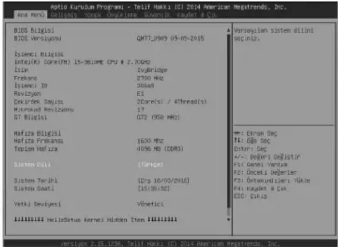
MAIN MENU
Main menu is the first menu displayed when you enter the Bios. You may see the basic information for your computer system and change the Bios language here. Definitions for titles in the main menu:
Bios : Displays the Bios version
System Language : Enables you to set the system configuration.
System Date : Enables you to set the system configuration.
System Time : Displays system time
CHAPTER 7
Power Management (Optional PC Unit)
In this section, we will describe how you may use your power settings in most effective way. Please read carefully the power management instructions below. This will ensure security and best performance of your system.
Following titles are covered under this section:
• Power management
• Critical points for power saving
You can adjust your power options in Power Management under Control Panel of Windows operating system:
| Result Situation | |
| Shutting down the hard disk | n case your system is unused for a given period |
| Turning off the screen In case | your system is unused for a given period |
| During hibernate mode: hard disk, screen and temporary memory (ram) voltage will be turned off for energy saving | In case your system is unused for a given period Press the power button |
| During sleep mode: both hard disk and screen will be shut down | In case your system is unused for a given period Press the power button |
Note: For more information about power management configuration, please refer to the relevant operating systems support pages.
• Critical points for power saving
You may do the following to provide some additional power saving apart from your "INTERACTIVE BOARD" automatic power saving:
- Enabling power management
• Decreasing the screen brightness as far as possible - Turning off the "INTERACTIVE BOARD" when it is not used
CHAPTER 8
USING YOUR "INTERACTIVE BOARD" MORE EFFICIENTLY
Paying attention to the following points with respect to your “INTERACTIVE BOARD” will provide a stable performance and also prolong its life. Following titles are covered under this section:
Securing your "INTERACTIVE BOARD"
The methods described here will help you protect your "INTERACTIVE BOARD" and your data.
• Using antivirus software
Especially after internet and e-mails became used widespread, the computers are now harmed easily by viruses. It is essential and recommended to use anti-virus software in order to prevent this harm.
Daily Maintenance
• Environmental factors
The working temperature of “INTERACTIVE BOARD” is 0 C° - 40 C°. Do not directly expose your “INTERACTIVE BOARD” to humidity, high temperature, fire, direct sun light and dust while using it. The vent holes of your “INTERACTIVE BOARD” will allow it perform safer without system overheating. Do not cover these holes or do not prevent air flow with an object. Please place “INTERACTIVE BOARD” at least 15 cm far from electrical devices generating magnetic area, as speakers.
- General points
Do not put heavy objects on "INTERACTIVE BOARD". The screen is extremely sensitive and may be damaged.
Never use hard cleaning materials on your screen. Do not touch the screen with sharp objects.
Do not disable the “backlight” setting from power management. Its automatic turn off is one of the factors ensuring its long-life.
- Points to be taken into consideration while cleaning the product
The system should not be active while “INTERACTIVE BOARD” is being cleaned. Use a soft and damp cloth to clean the surface of product. Do not use chemical cleaners to clean the screen. To clean the display screen, do not use chemical cleaners. Do not apply the cleaner directly on the “INTERACTIVE BOARD”.
CHAPTER 9
TROUBLESHOOTING
If you are experiencing any problem with your display, before calling for service, please review the following troubleshooting tips.
There is no picture or sound.
- Is the power cord disconnected? (See page 14)
- Is the product in standby mode (the power LED ON?) (See page 15)
- Make sure correct input mode is selected. (See page 13)
- If any external equipment is connected, make sure the equipment is operating (playing back).
Remote control does not work.
- Are the batteries inserted with polarity (+,-) aligned? (See page 14)
- Are the batteries exhausted?
- Point the remote control unit toward the product's remote control sensor. (See page 15)
• Is operation disabled? (See page 20)
Sound from left and right speakers is reversed.
- Are audio cables connected properly?
There is a picture but no sound.
- Is the sound muted?
- Make sure the volume is not set to minimum.
- Are audio cables connected properly?
Unstable video.
- The signal may be incompatible. (See page 28)
The video from the HDMI input terminal does not appear properly.
- Is the HDMI cable HDMI standard compliant? The product will not work with cables that are not standard compliant.
- Is the input signal compatible with this product? (See page 28)
- If an AV signal such as 1920 x 1080i, 720(1440) x 576i, or 720 (1440) x 480i is displayed using the HDMI [PC] input, display problems such as faint colors may occur.
The video from VGA input terminal does not appear properly.
- Is the input signal compatible with this product? (See page 28)
There is no picture.
- Load noises from outside may be interfering with normal operation. Turn off the power and turn it on after waiting at least 5 seconds, and then check the operation.
The product makes a cracking sound.
- You may occasionally hear a cracking sound from the product. This happens when the cabinet slightly expands and contracts according to change in temperature. This does not affect the product's performance.
Troubleshooting for the product with OPS PC
There is no picture or sound.
- Is the power cord disconnected? (See page 14)
- Is the product in standby mode (the power LED ON?) (See page 15)
- Make sure correct input mode is selected. (See page 13)
- If any external equipment is connected, make sure the equipment is operating (playing back).
- If OPS PC mode is selected and No Signal message is displayed, be sure that OPS PC properly fits its slot.
New device is not recognized
- Is the relevant driver installed correctly?
- Are the cables connected correctly?
• Is the external device get power?
System does not connect to the Network
- Is the network driver installed correctly?
- Are the network cables connected correctly?
- Are the network settings on system arranged correctly?
- Check the user name and password to connect the network.
Applications do not work
- Is the application installed correctly?
- If any error message is displayed read instructions document which may be given with application.
FREQUENTLY-ASKED QUESTIONS
Hardware problems
Symptom: "INTERACTIVE BOARD" does not recognize the new equipment.
Check the following:
Check that the relevant driver is installed properly. Carefully read the explanations in the manual of the hardware. Ensure that all cables are connected correctly and properly. Be sure that the external device powered.
Hard disk problems
Symptom: Hard disk does not appear at Bios information.
Check the following:
Check that your BIOS settings are adjusted properly. Hard disk module may be malfunctioning. Consult technical support to get support.
Symptom: The hard disk runs more and more slowly
Check the following:
Data written on your hard disk can be defragmented by the “Defragment” in the system tools under operating system. Performing a virus scan is also important since viruses may decrease a hard disks performance.
Symptom: The numeric characters that are generally on the right of the keypad do not write.
Check the following:
Make sure that the "Num Lock" indicator led is on.
Network problems:
Symptom: The system cannot access the network
Check the following:
Be sure that the network driver is installed correctly. Connect the network cable properly. Check that your systems network settings are adjusted correctly. Make sure you enter the correct user name or password. Check that the correct network protocols and settings are activated. Consult the network manager if your problem is not solved.
Sound Issues
Symptom: There is no sound from "INTERACTIVE BOARD".
Check the following:
Be sure that sound volume is not low and sound is not muted. Ensure that the sound driver and its application is installed properly. Check that your product is not in Hibernate mode. Check cable connections in case you use an external speaker.
Symptom: Recording function does not work.
Check the following:
Adjust playback and recording volume. Be sure that the recording source device is working properly.
Symptom: The external microphone and audio devices do not work.
Check the following:
Make sure that the cables are properly and firmly connected. Check that the driver is installed. Check sound settings and whether the system is muted or not.
Issues about turning on the system
Symptom: The system cannot be turned on.
Check the following:
Be sure that power cable is connected firmly.
USB device issues
Symptom: USB device doesn't work
Check the following:
Make sure that "the correct driver is installed for the USB device"
Other Issues: Check the USB cable
Symptom: System hour and date is not correct.
Check the following:
You can adjust system clock and date from BIOS or operating system. If the system clock and date is not displaying the value you have entered every time you turn the system on, your BIOS battery may be dead and you may need to change it. Consult to the technical service regarding this matter.
Restarting the "INTERACTIVE BOARD" product
If your "INTERACTIVE BOARD" system is frozen or stopping frequently because of an error, you may need to restart your system.
In case the product does not respond to an attempt to shut down from the operating system, hold down the power button for 4 seconds.
▲ Important!
Shutting "INTERACTIVE BOARD" down as described above results in loss of all unsaved data.
Warning!
This is an A class device. This device may cause radio interference in households and in similar places. Therefore, user shall take the required precautions.
Specifications and this manual may be modified without prior notification. Complies with WEEE Regulation.
SPECIFICATIONS
| Model Name UHD8410PC - UHD8410 | |
| Cabinet | 84990Aluminum Front CoverMetal Back CoverWHITE / BLACK |
| Display Specifications | |
| Native ResolutionBacklight TypeBrightness (Typical)Contrast Ratio(Typical)Viewing AngleAspect RatioActive Screen AreaOrientationDisplayable Colors | 3840x2610Edge LED35014008916:984.04 inches(2134.62mm) diagonalLandscapeRGB |
| Monitor Specifications | |
| Control Buttons PC On/Off | Source Menu / ExitTouch On/OffBrightness / Volume Selection (Function Select)Brightness / Volume Level IncreaseBrightness / Volume Level Decrease |
| Touch Screen Infrared | Touch Screen(10 Points touch screen support) |
| Glass AR-Anti Reflective, AG-Anti Glare | |
| I/O Ports 1 x VGA In | 1 x HDMI In (HDMI 1.4)1 x HDMI In (HDMI 2.0)1 x USB B-type connector(for external touch screen usage only)1 x Line In1 x Line OutRS-232 Connection |
| PC Board Specifications | |
| Processor Intel i5 | 8610ME |
| Chipset QM77 | |
| System Memory | 8GB 1333/1600MHz DDR-3 RAM |
| Network (Wired/Wireless) | LAN: 10/100/1000 Mbps LAN supportWLAN : 802.11 a/b/g/n |
| Data Storage 500 | GB HDD |
| Audio | 2x13.5 W Audio Output Power |
| I/O Ports | 1 x RJ45, 10/100/1000 Mbps Ethernet2 x USB 3.0 ports2 x USB 2.0 ports1 x Microphone In1 x Headphone Out2 x Wi-Fi Antenna Connector |
| Mechanical Specifications | |
| Bezel Width (Left/Right, Top/Bottom) 38 mm/38 mm, 38 mm / 38 mmDimensions (W x H x D) 1954 mm x 1139 mmx 109 mm | |
| Weight 106 kgNet (with stand)106kg + 60 kg | |
| VESA Mounting Hole Configuration Specifications 600 mm (w) x 400 mm (h) |
| Environmental Conditions |
| Operating Temperature 0 °C – 40 °COperating Humidity % 20 - 80 relative humidity |
| Storage Temperature -15 °C – 50 °CStorage Humidity % 20 - 80 relative humidity |
| Electrical Specifications | |
| Power Consumption | 110-240V AC, 50-60Hz, 5A |
| Standby Mode < 4 W | |
| Software Specifications | |
| Operating System Win | dows 10 |
| Accesorries |
| Remote Control |
| Power Cable |
| Information Booklet |
| HDMI Cable |
| 2 Antenna (WiFi connection) |
| Driver DVD |
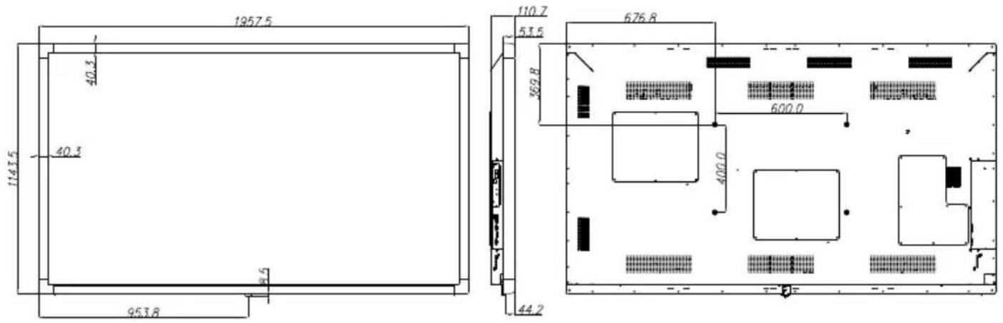
PRODUCT TECHNICAL DRAWING DETAILS
PRODUCT MEASUREMENTS MOUNTING MEASUREMENTS
OPS Connection Scheme
Tips
- OPS is an optional plug & play PC. It may be based on Intel or ARM based PC.
• DS monitor is complying with both Intel and ARM based OPS PC. - Connection Scheme refers to both Intel and ARM OPS PC.
OPS PC has an 80 pin OPS standard connection interface. Interconnection of ARM/Intel OPS PC and another board (i.e. docking board, monitor board or main board...) is provided by JAE TX/24TX25 plug and receptacle connectors.
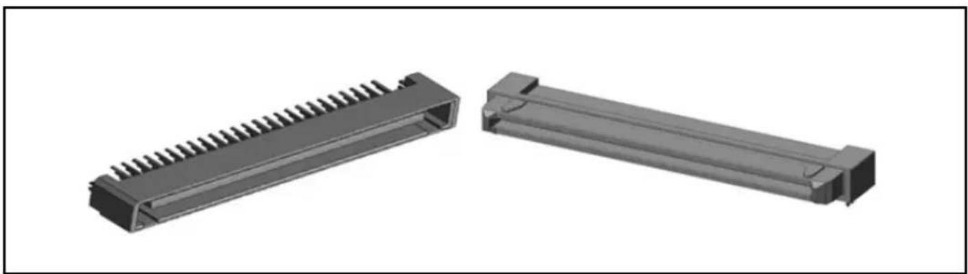
natural_image
Two 3D mechanical components with ribbed and rectangular ends, shown from different angles (no text or symbols visible)Left: OPS PC plug connector (p/n: TX25-80P)
Right: Receptacle connector (p/n: TX24-80P)
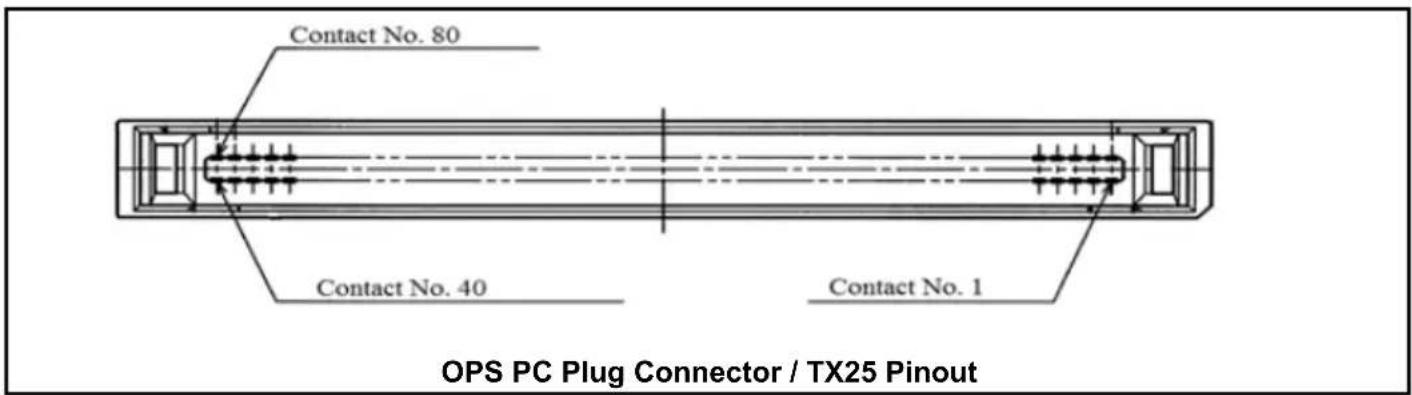
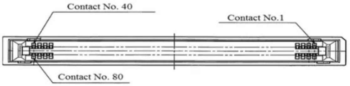
Receptacle Connector / TX24 Pinout
CHAPTER 10
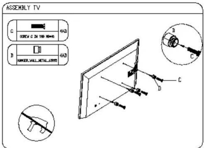
ASSEMBLY INSTRUCTION FOR INTERACTIVE MONITOR WALL MOUNT
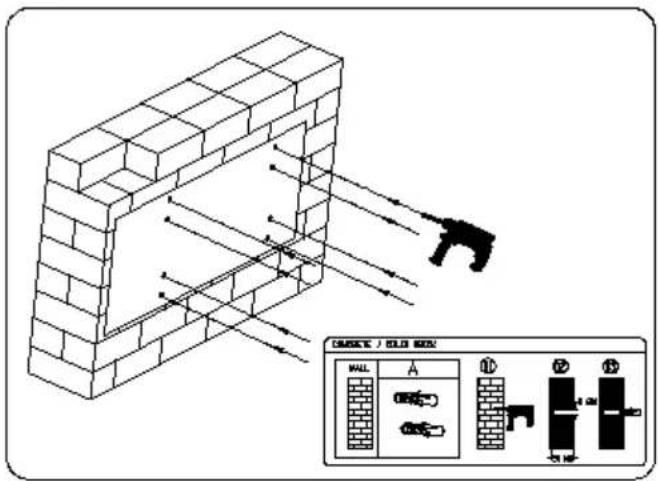
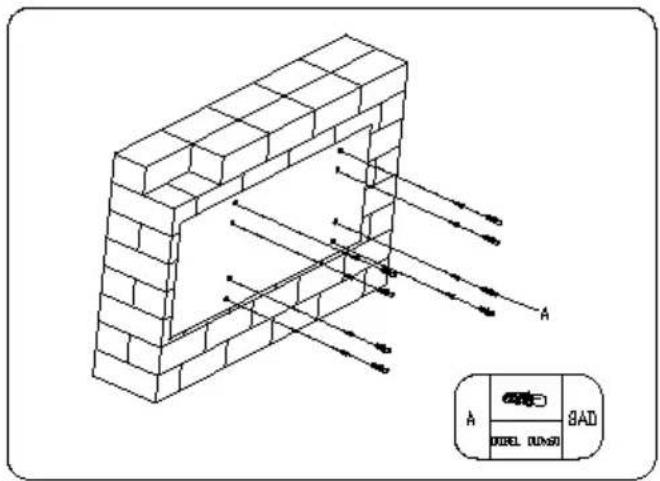
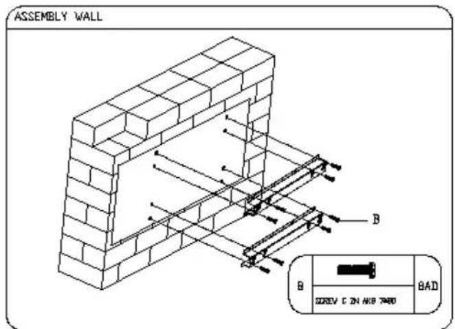
Use the monitor with the surface perpendicular to a level surface. Do not install the product on a ceiling or inclined wall.
HITACHI
Inspire the Next
Manufacturer:
Hitachi Europe Ltd.,
Whitebrook Park,
Lower Cookham Road,
Maidenhead,
Berkshire SL6 8YA
U.K.

- Important Safety Information
- CAUTION
- RISK OF ELECTRIC SHOCK DO NOT OPEN
- Please read these instructions carefully before use and keep for future reference
- Vent holes of the product
- Repair
- Replacement parts
- Safety checks
- Wall mounting
- Power Cord
- Especially for child safety
- Connections
- Transport and Shipping
- Intended Use
- Foreseeable misuse and incorrect use
- Warning
- BATTERY SAFETY GUIDELINES
- Introduction
- CHAPTER 1
- INTRODUCING THE "INTERACTIVE BOARD"
- CHAPTER 2:
- INFORMATION ABOUT USAGE OF "INTERACTIVE BOARD" and ITS FUNCTIONS Turning on and off your "INTERACTIVE BOARD"
- ▲ Important!
- Part Names
- OPS (Open Pluggable Specification) PC- Optional
- Tips
- USB 3.0 Ports
- USB 2.0 Ports (Optional)
- Lan Terminal
- Microphone and Headphone terminals
- Storage Unit
- CONNECTING PERIPHERAL EQUIPMENT
- Caution!
- AC Input Terminal
- RS-232 Input Terminal
- Line In/Out Terminals
- VGA Input Terminal
- USB B-Type Input Terminal
- HDMI input terminal x 2
- BASIC OPERATION
- 1-17. ON/OFF
- 2-16. Source Select (Input mode selection)
- Touch Screen (On/Off) Button
- Volume/Brightness Button
- 5-6. Up/Down +/- (Volume/Brightness adjustment)
- 7-8. Brightness +/- (Brightness adjustment)
- Use these buttons to adjust the brightness.
- 9-10. Vol +/- (Volume adjustment)
- Menu
- Mute
- Display On/Off
- Information
- Warning!
- Function Buttons and Remote Control
- Definition of Source Transition
- Definition of Source Transition by Button Chart
- Source Switching with remote control Description
- CHAPTER 3
- Touch screen
- Using the Touch Screen with External Source
- Touch Screen Installation
- About installation
- Function Description
- Operating steps
- Connections Diagram
- ▲Important!
- CHAPTER 4
- Connecting the USB devices
- Updating of internal devices
- Usage of External Sources with Interactive Board (HDMI-VGA)
- Mic and Audio in "INTERACTIVE BOARD"
- CHAPTER 5
- Processing System
- Windows 10
- Drivers
- Screen Resolution of "INTERACTIVE BOARD"
- Network Connection (Optional Pc Unit)
- Using the Network Connection Option
- Wireless Network Connection
- Windows 10 System Recovery
- CHAPTER 6:
- SYSTEM BIOS INFORMATION USING BIOS ACTIVELY (Optional PC Unit)
- Using BIOS actively
- Using Aptio Installation Software
- Settings
- MAIN MENU
- CHAPTER 7
- Power Management (Optional PC Unit)
- CHAPTER 8
- USING YOUR "INTERACTIVE BOARD" MORE EFFICIENTLY
- Securing your "INTERACTIVE BOARD"
- Daily Maintenance
- CHAPTER 9
- TROUBLESHOOTING
- FREQUENTLY-ASKED QUESTIONS
- Hardware problems
- Check the following:
- Hard disk problems
- Sound Issues
- Restarting the "INTERACTIVE BOARD" product
- PRODUCT TECHNICAL DRAWING DETAILS
- OPS Connection Scheme
- CHAPTER 10
- HITACHI
- Inspire the Next
Brand : HITACHI
Model : UHD8410
Category : Monitor