
CMP4121HDU - Monitor HITACHI - Free user manual and instructions
Find the device manual for free CMP4121HDU HITACHI in PDF.


| Product Type | Monitor |
| Brand | Hitachi |
| Model | CMP4121HDU |
| Display Technology | Plasma |
| Screen Size | 41 inches (104 cm diagonal) |
| Aspect Ratio | 4:3 |
| Native Resolution | 1024 x 768 pixels |
| Brightness | 1100 cd/m² |
| Contrast Ratio | 3000:1 |
| Horizontal Viewing Angle | 160 degrees |
| Vertical Viewing Angle | 160 degrees |
| Dimensions (W x H x D) | 1010 x 630 x 95 mm |
| Weight | 29.5 kg (without stand) |
| Power Supply | AC 100-240V, 50/60 Hz |
| Power Consumption (Typical) | 350 W |
| Power Consumption (Standby) | < 1 W |
| Video Inputs | VGA x1, DVI-D x1, Composite (RCA) x1, S-Video x1, Component (YPbPr) x1 |
| Audio Inputs | Stereo RCA x2 |
| Audio Output | 3.5 mm headphone jack, internal speakers (2 x 10 W) |
| VESA Mount | 400 x 400 mm |
| Remote Control | Included (model RC-1221) |
| Operating Temperature | 0°C to 40°C |
| Storage Temperature | -20°C to 60°C |
| Humidity | 20% to 80% non-condensing |
| Cleaning Instructions | Use soft dry cloth; avoid liquid or abrasive cleaners. Unplug before cleaning. |
| Safety Precautions | Do not expose to rain or moisture. Ensure proper ventilation. Unplug during storms or long idle periods. |
| Repair Policy | Only qualified technicians. No user-serviceable parts inside. Contact Hitachi service center. |
Frequently Asked Questions - CMP4121HDU HITACHI
User questions about CMP4121HDU HITACHI
0 question about this device. Answer the ones you know or ask your own.
Ask a new question about this device
Download the instructions for your Monitor in PDF format for free! Find your manual CMP4121HDU - HITACHI and take your electronic device back in hand. On this page are published all the documents necessary for the use of your device. CMP4121HDU by HITACHI.
USER MANUAL CMP4121HDU HITACHI
2000 Sierra Point Parkway. Brisbane,
Ca 94005-1835, U.S.A
Tel:+1-800-HITACHI
Fax:+1-650-244-7525
Hitachi Australia Ltd.
Level 3, 82 Waterloo Road, North Ryde N.S.W. 2113
Tel:+61(02)9888-4100
Fax:+61(02)9888-4144
Hitachi Home Electronics Asia (S)Pte. Ltd.
16 Collyer Quay, #20-00 Hitachi Tower, Singapore 049318
Tel:(65)6536-2520
Fax:(65)6536-2521
HITACHI (HONG KONG) LIMITED
18/F., Ever Gain Centre, 28 On Muk Street,
Shatin, N.T. Hong kong.
Tel:(852)2113 8883
Fax:(852)2780 4178
Color Plasma Display Monitor
USER'S MANUAL
MANUEL UTILISATEUR
取扱説明書
READ THE INSTRUCTIONS INSIDE CAREFULLY. KEEP THIS USER'S MANUAL FOR FUTURE REFERENCE.
For future reference, record the serial number of your monitor.
SERIAL NO.
The serial number is located on the rear of the monitor.
This monitor is ENERGY STAR® compliant when used with a computer equipped with VESA DPMS.
The ENERGY STAR® emblem does not represent EPA endorsement of any product or service.
As an ENERGY STAR® Partner, Hitachi,Ltd. has determined that this product meets the ENERGY STAR® guidelines for energy efficiency.

Contents related to system specifications, power requirements, accessories, and other information differ with respect to the country where this unit is purchased. For customers living in the U.S.A. or Canada, please use and refer to the instructions written in either English or French. For customers in Japan, please use and refer to the instructions written in Japanese.
The information in this manual is subject to change without notice. The manufacturer assumes no responsibility for any errors that may appear in this manual.
TRADEMARK ACKNOWLEDGEMENT
VGA and XGA are registered trademarks of International Business Machines Corporation.
APPLE and Macintosh are registered trademarks of Apple Computer, Inc.
VESA is a trademark of a nonprofit organization, Video Electronics Standard Association.
All brand or product names are trademarks or registered trademarks of their respective holders.
REMARQUE:
Thank you very much for purchasing the HITACHI Plasma Display Monitor.
Before using your monitor, please carefully read the "SAFETY GUIDELINES" and this "USER'S MANUAL" so you will know how to operate the monitor properly. Keep this manual in a safe place. You will find it useful in the future.
Notes on Installation Work:
This product is marketed assuming that it is installed by qualified personnel with enough skill and competence. Always have an installation specialist or your dealer install and set up the product. HITACHI cannot assume liabilities for damage caused by mistake in installation or mounting, misuse, modification or a natural disaster.
Note for Dealers:
After installation, be sure to deliver this manual to the customer and explain to the customer how to handle the product.
FEATURES CONTENTS
Large-screen, high-definition plasma display panel
The 42-inch color plasma display panel, with a resolution of 1024 (H) x 1024(V) pixels, creates a high-definition, large-screen (aspect ratio : 16:9) and low-profile flat display. Free from electromagnetic interferences from geomagnetic sources and ambient power lines, the panel produces high-quality display images free from color misconvergence and display distortion.
Multimedia input support
Two mini D-sub terminals have been provided for RGB input. It is possible to switch between RGB signals and component signals* from the Menu screen; therefore, use is possible with equipment ranging from personal computers to imaging devices. A speaker output terminal has also been provided.
* It is possible when the VIDEO unit of an option is inserted.
Multiscan converter and Flexible Control LSI
A wide range of personal computer signals can be handled, from 640 x 400, 640 x 480 VGA to 1600 x 1200 UXGA.
Easy-to-use remote controller and on screen display system
The remote controller included eases the work of setting display controls. Further, the on-screen display system, displays the status of signal reception and display control settings in an easy-to-view fashion.
Power saving system
The International ENERGY STAR® power saver feature saves power consumption automatically when input signals are not available. When connected to a VESA DPMS-compliant PC, the monitor cuts its power consumption while it is idle.
About the Optional Video Unit
The following functions can be obtained by connecting the optional video unit.
(1) A composite/S terminal and component terminal have been added. A composite video output terminal is also provided for use as a loop-through function.
(2) A wide range of devices other than personal computers can also be connected.
(3) A component input is attained at a D-Sub terminal (RGB1, RGB2).
(4) The SCART signal of the European standard becomes possible.
Options
Ask your local retail dealer for further details.
- Desktop stand: CMPAD05
-
Wall-mount unit:
Horizontal mount: CMPAK05
Vertical/horizontal mount: CMPAK15
These are brackets used to mount this device on a wall. -
Ceiling-suspension unit: CMPAT05
-
Plasma monitor speaker: CMPAS04 (width:10.2mm)
This is a two-way speaker with one 2.5cm dome type tweeter and two 8cm round type woofers.
- Video unit: CMPAV14
An expansion unit for viewing video with this device.
FEATURES 2
SAFETY GUIDELINES ....3
STANDARD ACCESSORIES ....7
Component Names ....8
Main Unit....8
Remote controller 9
Loading Batteries 9
Handling the Remote Controller 9
INSTALLATION INSTRUCTIONS ....10
Installation....10
Anti-tumble measures....10
Connecting to a PC 11
Connecting to a Video Imaging Device 12
Power Cord Connection 13
Mounting the Video Unit 13
Mounting the Speaker Unit 13
OPERATING INSTRUCTIONS ....14
Turning Power On and Off 14
Input Switching 15
Volume Adjustment....15
Audio Mute 15
Size Switching 16
Displaying Two Screens 16
Input Signal Screen Display 16
Automatic Adjustment of Screen Position and the Clock ..17
Independent Operation of Multiple Monitors ....17
Using the Menu Screen 17
PICTURE MENU 18
SOUND MENU 19
DISPLAY MENU 20
FUNCTION MENU 22
OTHER MENU 23
OTHER FEATURES ......24
Automatic Store 24
Signal Check 24
Power Save Mode....25
TWO SCREEN TABLE....25
IMAGE RETENTION OF PLASMA DISPLAY .....26
NOTES 26
TROUBLESHOOTING 27
Symptoms That Seemingly Appear to be Failures .....27
Actions to Correct Abnormal Displays 29
PRODUCT SPECIFICATIONS ....30
Signal Input....31
Recommended Signal List ....31
Notes about This Manual
- The information in this manual is subject to change without notice.
- While meticulous care has been taken in the preparation of this manual, you are requested to notify your dealer or us should you have any comments, views or questions about our product.
- Fully understand the prerequisites to using the product, such as hardware and software specifications and constraints, in using the product. We are not held liable for damages caused by improper handling of the product.
- Reproduction of this manual in whole or in part without our prior written permission is prohibited.
• The product names mentioned in this manual may be trademarks or registered trademarks of their respective owners.
SAFETY GUIDELINES
This monitor is designed to be safe to use. However, fire or serious injury may occur unless you use this monitor in the proper way. Please follow the instructions shown below in order to avoid injury.

Keep the safety guideline
Do not use the monitor if it fails
If you find something unusual,
* If smoke comes out,
* If there is a strange smell,
* If water enters the case,
* If you drop the monitor or damage the cabinet,

(1) Turn off the monitor
(2) Disconnect the power plug from the mains
(3) Request repair
Warning and Caution are indicated in this guide and monitor itself.

WARNING
Fire or electric shock may cause death or serious injury unless you follow the instruction.

CAUTION
Electric shock or other accidents may cause serious injury or damage of your properties.

WARNING
Fire or electric shock may cause death or serious injury unless you follow the instruction below.
- If something smells strange or smoke comes from the monitor:
Turn off the monitor and disconnect the power plug from the mains immediately.
Contact service center after confirming that the smoking has stopped.
If you continue to operate the monitor with such abnormal condition, it may cause fire or you may receive an electric shock.
- Do not drop water or a foreign substance on to the monitor.
If you drop water or a foreign substance on to the monitor, it may cause fire or an electric shock.
If it happens turn off the monitor and disconnect the power plug from the mains and ask service center for instruction.
- Do not put the monitor on an unstable place.
If you put the monitor on an uneven or unstable place, it may fall down and you may be injured.
Put the monitor on a flat surface strong enough to take the weight.
- Do not apply shock to the monitor.
- Do not use monitor if glass is broken or damaged.
If there is no picture appearance, broken glass, smoking or something smells after applying shock to the monitor, turn off the monitor and disconnect the power plug from the mains immediately. Then, call the service center.
If you continue to operate the monitor with such abnormal conditions, it may cause fire or you may receive an electric shock.
- Do not disassemble or modify the monitor.
There is high voltage portion inside of the monitor. Disassembling or modification of the monitor may cause fire or electric shock.
- Do not use the monitor in wet environment.
If you use the monitor in a wet place such as bath or shower room, it may cause fire or electric shock. Using the monitor beside a window when snowing or raining or by a seaside are not recommended.
- Do not damage or modify the power cord.
If you put something heavy on the power cord or pull, squeeze, heat the cord, it may be damaged and it may cause fire or electric shock. If the power cord is damaged, call service center.
SAFETY GUIDELINES(continued)

WARNING
Fire or electric shock may cause death or serious injury unless you follow the instruction.
- The enclosed power cord must be used!
Failure to do so may cause electric shock hazard or fire hazard.
In USA/Canada, use a UL LISTED/CSA LABELLED or CERTIFIED power cord set meeting the following specifications :
Rating: min. 125V, 10A, Length: max. 3.0m, Type: SVT or SJT
Plug type: NEMA 5-15P figure, Parallel blade, Grounding type
In Europe or 200V area, a proper European standard approved power cord is to be used with this monitor.
For a rated current up to 6 A, a type not lighter than H05VV-F 3G 0.75 mm ^2 or H05VVH2-F 3G 0.75 mm ^2 must be used.
- Use only the correct voltage power outlet with safety ground connection!
100 - 120 V for USA, Canada, etc.
200 - 240 V for Europe, etc.
(This monitor will automatically adjust to the input voltage 100 - 120 / 200 - 240V.)
- Be careful of power cord connection!
Before inserting the plug of the power cord into a socket of the correct voltage, check that the connection portion of the power cord is clean (with no dust). Then, insert the plug of power cord into the socket firmly, otherwise it may cause electric shock or fire hazard.
- Do not touch the power plug when lightning is close to you.
You may receive an electric shock.
- Do not touch the power plug with wet hands.
You may receive an electric shock.
- Do not obstruct a ventilation hole.
If you obstruct a ventilation hole during the operation of the monitor or just after switching off the power, it may cause a fire or electric shock due to heating up the monitor.
- Do not put the monitor screen side up.
- Do not put the monitor on a shelf or in a cabinet without adequate ventilation of 4 inches top, sides, bottom and rear.
- Do not put the monitor on a carpet or mattress.
- Do not cover the monitor with a cloth.

CAUTION
Electric shock or other accidents may cause serious injury or damage to your property.
- Disconnect the power plug from the mains when you move the monitor.
Moveing the monitor without disconnecting the power plug from the mains may damage the cord and cause a fire or electric shock. You are advised to move the monitor with two persons.
Handle with care when you move the monitor, particularly take care of glass screen.
- When you disconnect the power plug.
You have to grasp the power plug itself, do not pull the power cord.
If you pull the power cord, you may damage it and it may cause a fire or an electric shock.
Do not touch the power plug just after disconnecting it from the mains or you may receive electric shock.
- Disconnect the power plug from the mains when you don't use the monitor for a long time.
This is for your safety.
- Do not put the monitor in atmosphere with soot, steam, high humidity, and dust.
It may cause a fire or electric shock.
- Do not put the monitor in high temperature atmosphere.
Do not put the monitor in the place exposed to the direct rays of the sun for a long period of time. Heat may cause a fire, transformation, or melting of the monitor.
- Do not put things on the monitor.
Do not put things on the monitor or give some shock to the monitor.
The monitor may fall down or drop from a desk. And it may cause injury.
SAFETY GUIDELINES(continued)

CAUTION
You may have serious injury or your property may be damaged unless you follow the instruction below.
- Do not coil or wind the power cord.
This may cause excessive heat resulting in a fire.
- Caution for 200 - 240V operation only
This equipment relies on the protective devices in the building installation for short - circuit and over - current protection. Refer to the following table for the suitable number and location of the protective devices which should be provided in the building installation.
INFORMATIVE EXAMPLES OF PROTECTIVE DEVICES IN SINGLE - PHASE EQUIPMENT OR SUB - ASSEMBLIES
| Protection against | Minimum number of fuses or circuit - breaker poles | Location | |
| Case A: Equipment to be connected to POWER SYSTEMS with earthed neutral reliably identified, except for Case C below. | Earth faults 1 | Phase conductor | |
| Overcurrent 1 | Either of the two conductors | ||
| Case B: Equipment to be connected to any supply, including IT POWER SYSTEMS and supplies with reversible plugs, except for Case C below. | Earth faults 2 | Both conductors | |
| Overcurrent 1 | Either of the twoconductors | ||
| Case C: Equipment to be connected to 3 - wire power systems with earthed neutral reliably identified. | Earth faults 2 | Each phase conductor | |
| Overcurrent 2 | Each phase conductor |
Verify that the protective devices in the building installation meets the conditions in the table prior to installing the equipment.
- Remove the power cord for complete isolation!
For complete isolation from the mains, remove the power cord from the monitor or from the wall socket.
PRECAUTIONS
• Installation environment
Do not obstruct a ventilation hole.
Do not put the monitor on carpet or blanket, or near a curtain which has a possibility of obstructing a ventilation hole of the monitor.
Do not put the monitor in the following places.
- Hot places such as near heater, place exposed to the direct rays of the sun.
- A place where the temperature is widely changing.
- Places with soot, dust or high humidity.
- Poor air ventilation place.
- Place near fire.
- A wet place such as bathroom, or shower room.
- Place where you can trip over it.
• Always vibrating or strongly vibrating places.
• Distorted or unstable places.
• How to view the monitor.
If you use the monitor in too dark a room, your eyes may become tired.
Please use it in a reasonably bright room.
Avoid direct rays of the sun to the screen in order to prevent eye fatigue.
Your eyes will get fatigued after viewing the monitor for long period of time.
Relax your eyes by viewing away from the monitor from time to time.
Please watch the monitor in downward direction.
• Note on image retention
The plasma monitor illuminates phosphor to display images. The phosphor has a finite illumination life. After extended periods of illumination, the brightness of the phosphor would be degraded to such extent that still images would image retention that part of the screen as grayed-out images.
Tips to prevent such image retention are:
- Do not display images having sharp brightness differences or high-contrast images, such as monochrome characters and graphic patterns, for long.
- Do not leave stationary images appearing for long, but try to refresh them at appropriate intervals of time, or try to move them using screen saver function.
- Turn down the contrast and brightness controls.
SAFETY GUIDELINES(continued)
PRECAUTIONS(continued)
• How to clean the monitor.
Before cleaning the monitor, turn off the monitor and disconnect the power plug from the mains.
When cleaning the monitor, do not spray directly the screen or cabinet with cleaner.
Use a clean, dust free, dry and soft cloth. If it is not enough, then use a cloth with non-alcoholic or non-ammonia detergent.
Do not rub the surface of the screen with ball-point-pen or screw-driver etc.
• Prevention of an obstacle to Radio receivers
This monitor has been designed pursuant to the FCC class B Rules (see as below). This is to prevent a problem to Radio receivers.
- Keep the monitor away from Radio.
- Adjust Radio antennas in order for the monitor not to receive interference.
- The antenna cable of Radio should be kept away from the monitor.
- Use a coaxial cable for antenna.
You can check if this monitor influences Radio receivers by turning off all other equipment other than the monitor.
If you find a problem receiving Radio when using the monitor, check the instructions mentioned above.
• Precautions for the monitor
- Use the attached signal-cable when you connect the monitor with PC equipment.
Do not use other signal-cables.
- Confirm the connector is fixed tightly when the signal cable is connected.
Also confirm the screws on the connector are tightened.
- Plug the power cord of the monitor into a different socket from that for other equipment, such as Radio etc..
- Use a plug with ground terminal and make sure that it connects to the ground.
• Precaution during transportation
Please pay attention when you transport this monitor because it is heavy.
Furthermore, use the original carton box and its packaging materials when the monitor is transported.
Failure to transport the monitor in any carton except the original carton may result in damage to the monitor.
Save the original carton box and all packing material.
• FCC (Federal Communications Commission) STATEMENT WARNING
For model PD1 / CMPAV14 (Plasma Display / Video Unit)
WARNING: This equipment has been tested and found to comply with the limits for a Class B digital device, pursuant to Part 15 of the FCC Rules. These limits are designed to provide reasonable protection against harmful interference in a residential installation. This equipment generates, uses, and can radiate radio frequency energy and, if not installed and used in accordance with the instructions, may cause harmful interference to radio communications. However, there is no guarantee that interference will not occur in a particular installation. If this equipment does cause harmful interference to radio or television reception, which can be determined by turning the equipment off and on, the user is encouraged to try to correct the interference by one or more of the following measures:
- Reorient or relocate the receiving antenna.
- Increase the separation between the equipment and receiver.
- Connect the equipment into an outlet on a circuit different from that to which the receive is connected.
- Consult the dealer or an experienced radio / TV technician for help.
Instructions to Users: This equipment complies with the requirements of FCC (Federal Communication Commission) regulations, provided that following conditions are met.
Video inputs : The input signal amplitude must not exceed the specified level.
CAUTION : Changes or modifications not expressly approved by the party responsible for compliance could void the user's authority to operate the equipment.
Declaration of Conformity
According to 47CFR, Part 2 and 15 for
Class B Personal Computers and
Peripherals; and / or
CPU Boards and Power Supplies used
with Class B Personal Computers:
We: Hitachi America, Ltd. Computer Division
Located at: 2000 Sierra Point Parkway, Brisbane, CA 94005-1835, U.S.A.
Telephone: 1-800-HITACHI
Declare under sole responsibility that the product identified herein, complies with 47CFR Part 2 and 15 of the FCC rules as a Class B digital device. Each product marketed, is identical to the representative unit tested and found to be compliant with the standards. Records maintained continue to reflect the equipment being produced can be expected to be within the variation accepted, due to quantity production and testing on a statistical basis as required by 47CFR § 2.909. Operation is subject to the following two conditions: (1) This device may not cause harmful interference, and (2) This device must accept any interference received, including interference that may cause undesired operation. The above named party is responsible for ensuring that the equipment complies with the standards of 47CFR § 15.101 to 15.109.
Trade name: Plasma Display Monitor with Video Unit
Model Number: PD1 (Plasma Display)
CMPAV14 (Video Unit)
STANDARD ACCESSORIES
This product is complete with the display monitor, plus the accessories shown below.
- If any of these accessories is missing, please contact your dealer.
User manual (this book)
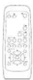
Remote-control transmitter

Size AA batteries x 2
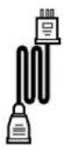
Power cable
- Read the user manual (this book) and keep them in a safe place for handy reference.
- Retain the packing materials for use in future shipping or relocation.
Component Names
Main Unit
Front

Control panel
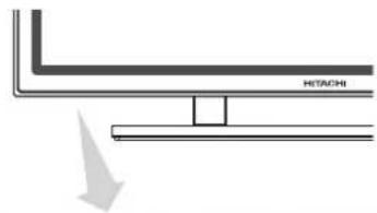
- Adjustment buttons are located on the bottom.
- The back cover is provided with indications to distinguish the adjustment buttons.

natural_image
Simple line drawing of a hand pressing a horizontal bar with 'H13A0H' label (no other text or symbols)
- The main power switch is located at the back, on the lower surface.
Main power switch
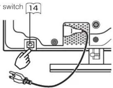
Rear
Caution when moving the main unit
- As this product is heavy, whenever it is moved, two people are required to transport it safely.
- Whenever the unit is moved it should be lifted forwards using the two handgrips at the back, and the unit should then be held at the base on both sides for stability.

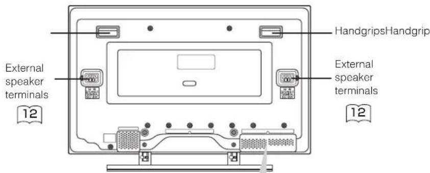
External device connection terminals

Component Names (continued)
Remote controller

Loading Batteries
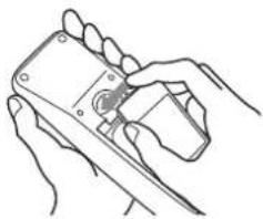
1. Open the battery cover.
- Slide back and remove the battery cover in the direction of the arrow.

natural_image
Line drawing of hands holding a handheld device (no text or symbols visible)2. Load batteries.
- Load two Size AA batteries included observing the correct polarities.

natural_image
Technical line drawing of a remote control casing with mounting holes and a handle (no text or symbols)3) Close the battery cover.
- Replace the battery cover in the direction of the arrow and snap it back into place.
natural_image
Line drawing of two hands holding a handheld device (no text or symbols)CAUTIONS
- Do not use new and old batteries together. The batteries could explode or leak, resulting in fires, physical injury, or stains.
- When loading batteries, observe their correct polarities as marked on the product. If loaded in the wrong direction, the batteries could explode or leak, resulting in fires, physical injury, or stains.
Handling the Remote Controller
Use the remote controller within about 5 m from front of the unit's remote-control sensor and within 30 degrees on both sides.

TIPS
- Do not drop or impact the remote controller.
- Do not splash the remote controller with water or put it on a wet object to avoid possible failures.
- Before leaving the remote controller out of use for an extended period of time, remove the batteries from it.
- If the remote controller begins to lack responsiveness, replace the batteries.
- Strong light such as direct sunlight impinging on the photoreceptor of the remote control can cause operational failure. Position this unit to avoid direct contact with such light.
INSTALLATION INSTRUCTIONS
Installation
No stand is provided with this product. When installing the monitor, use the optional Desk-top Stand (CMPAD05), Wall Mount Unit (horizontal-mount CMPAK05, vertical/horizontal-mount CMPAK15), or Ceiling Mount Unit (CMPAT05).
The Desk-top Stand has been used for the illustrations in this manual.
WARNING
Use one of the special mount units to install this product. A mount of insufficient strength or inadequate design can cause overturning or dropping and result in fire, electrical shock or injury. Please note that our company assumes absolutely no responsibility for personal injuries or property damage caused by use of other mount units or improper installation.
CAUTIONS
• Installation of the wall mount unit and ceiling mount unit can be dangerous, so do not attempt this work yourself. Ask your dealer to provide the name of a qualified installer.
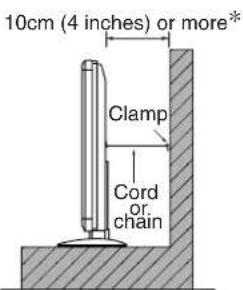
- In order to prevent an internal temperature increase, maintain a space of 10cm (4 inches: For a desktop set-up) or more between the sides and other objects such as walls, etc., so that the ventilation holes are not blocked.*

Anti-tumble measures
CAUTIONS
Have this unit mounted in a stable place. Take measures to prevent it from tumbling down to avoid possible physical injury.
Securing to a wall or pillar
Using a commercially available cord, chain and clamp, secure the set to a firm wall or pillar.
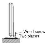
Securing desktop
1) Using wood screws (two), fasten the set to the clamping screw holes on the rear of the stand as shown.
2) Using commercially available wood screws, secure the set firmly in position.
Using the optional vertical-mount unit (CMPAK15)
Using the optional wall-mount unit (CMPAK15) allows set to mount on wall surfaces as shown at below.
1) Make at least four sets of commercial anchor bolts and screws available to meet various kinds of walls to mount on.
2) Read the instructions supplied with the wall-mount unit carefully to optimally locate the plasma display on a wall surface.
3) Prepare the wall surface for anchoring and drilling as needed, as shown in the sketches.
- Make sure that an adequate wall surface strength and a screw holding strength are available.

Horizontal mounting Upper left vertical mounting
Horizontal mounting

natural_image
Technical line drawing of a device rear panel with connectors and buttons (no text or symbols)Plasma display outline
Upper left vertical mounting

natural_image
Technical diagram showing side view of a device with internal components and mounting points (no text or symbols)Plasma display outline
Driving anchor bolts into a wall surface

CAUTIONS
The mounted unit should have the indicating lamp at its bottom. Otherwise, an elevated internal temperature rise could cause the unit to fail or fire.
INSTALLATION INSTRUCTIONS (continued)
Read SAFETY GUIDELINES (3 to 6) carefully to ensure maximum safety before proceeding to these steps:
- Choose an appropriate site and install the product on a level table where the stand is secure.
• Install the monitor to have ready access to a power socket available. - Make sure that the power switch of this device is turned off.
Connecting to a PC
(1) Make sure that the display signal of the personal computer to be used is compatible with the specifications of this device.
• See "Product Specifications" concerning the specifications of this device.
(2) Make sure that the power switch of the personal computer is turned off.
(3) Connect the signal input terminal (RGB 1 or RGB 2) on the rear panel of this device to the display signal output terminal of the personal computer.
- Use a cable that fits the input terminal of this device and the output terminal of the personal computer.
- Depending on the type of personal computer being connected, the use of an optional conversion adapter or the adapter provided with the personal computer may be necessary in some cases. For details, refer to the instruction manual of the personal computer or ask the personal computer manufacturer or your local retail dealer.

INSTALLATION INSTRUCTIONS (continued)
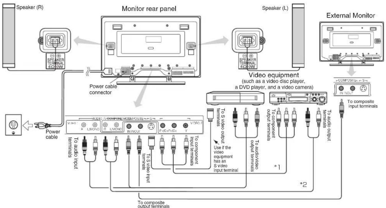
Connecting to a Video Imaging Device (When the optional video unit is installed.)
(1) Make sure that the power switch of the imaging device is turned off.
(2) Use a commercially available cable and connector to connect the signal input terminal on the rear panel of this device and the signal output terminal of the imaging device.
flowchart
graph TD
    A["Speaker (R)"] --> B["Monitor rear panel"]
    B --> C["Speaker (L)"]
    B --> D["Video equipment"]
    D --> E["External Monitor"]
    B --> F["Power cable connector"]
    F --> G["Power cable"]
    G --> H["To audio input terminals"]
    G --> I["To video input terminals"]
    G --> J["To S video input terminals"]
    G --> K["To component input terminals"]
    G --> L["To composite output terminals"]
    M["Speaker (L)"] --> N["Speaker (R)"]
    O["External Monitor"] --> P["Speaker (L)"]
    Q["Power cable"] --> R["Power cable connector"]
    R --> S["Power cable connector"]
    T["Video equipment"] --> U["To video output terminals"]
    U --> V["To video output terminals"]
    W["External Monitor"] --> X["External Monitor"]
    Y["Power cable"] --> Z["Power cable connector"]
    AA["Power cable"] --> AB["Power cable connector"]
    AC["Power cable"] --> AD["Power cable connector"]
    AE["Power cable"] --> AF["Power cable connector"]
    AG["Power cable"] --> AH["Power cable connector"]
    AI["Power cable"] --> AJ["Power cable connector"]
    AK["Power cable"] --> AL["Power cable connector"]
    AM["Power cable"] --> AN["Power cable connector"]
    AO["Power cable"] --> AP["Power cable connector"]
    AQ["Power cable"] --> AR["Power cable connector"]
    AS["Power cable"] --> AT["Power cable connector"]
    AU["Power cable"] --> AV["Power cable connector"]
    AW["Power cable"] --> AX["Power cable connector"]
    AY["Power cable"] --> AZ["Power cable connector"]
    BA["Power cable"] --> BB["Power cable connector"]
    BC["Power cable"] --> BD["Power cable connector"]
    BE["Power cable"] --> BF["Power cable connector"]
    BG["Power cable"] --> BH["Power cable connector"]
    BI["Power cable"] --> BJ["Power cable connector"]
    BK["Power cable"] --> BL["Power cable connector"]
    BM["Power cable"] --> BN["Power cable connector"]
    BO["Power cable"] --> BP["Power cable connector"]
    BQ["Power cable"] --> BR["Power cable connector"]
    BS["Power cable"] --> BT["Power cable connector"]
    BU["Power cable"] --> BV["Power cable connector"]
    BW["Power cable"] --> BX["Power cable connector"]
    BY["Power cable"] --> BZ["Power cable connector"]
    CA["Power cable"] --> CB["Power cable connector"]
    CC["Power cable"] --> CD["Power cable connector"]
    DD["Power cable"] --> DJ["Power cable connector"]
    DK["Power cable"] --> DL["Power cable connector"]
    DV["Power cable"] --> DW["Power cable connector"]
    DX["Power cable"] --> DXB["Power cable connector"]
    DXB --> DXC["Power cable"]
- If video equipment with an S video output terminal is used, cabling by the S video cable is recommended to provide finer video quality. (If an S video input terminal and a video input terminal connect to the monitor at the same time, S video input would govern.)
- If the VIDEO1 OUT terminal is connected to an external monitor with a 75 Ohm terminal, it is possible to view the same image as on the main unit. If an external monitor is not being used, the cable must be removed from the VIDEO OUT terminal. The image will appear white as saturation level is reached.
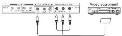
With RGB component setup

With SCART terminal connection (refer to 22)
Speaker Connection
This device is equipped with speaker output jacks for use in connecting a speaker system (optional). Refer to the diagram below to connect.
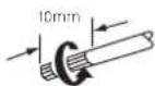
Remove the insulation and twist the bare cable as shown.
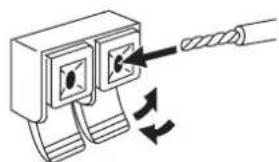
natural_image
Diagram of a cable connector with two terminals and directional arrows indicating cable movement (no text or symbols)Down the tab and insert the cable. Press the tab up to prevent the cable being pulled out.
CAUTIONS
When connecting speakers, connect the plus (+) speaker terminal and the plus (+) speaker terminal of this device, and connect the respective minus (-) terminal in the same way. The sound will not be correct if plus (+) and minus (-) terminal are connected to each other.
INSTALLATION INSTRUCTIONS (continued)
Power Cord Connection
Connect the power cord, after completing all other connections.

(1) Connect the power cord to this device.
(2) Connect the power cord plug to the power outlet.
CAUTIONS
- Use only the power cord provided.
- Do not use a power supply voltage other than that indicated (AC100-240V, 50/60Hz) as this may cause fire or electric shock.
- To maintain the correct performance level, use a 3-core power cord with ground wire attached.
- When connecting the power cord, use a grounded power outlet and make sure that the power cord is properly grounded.
- When using a power cord plug adapter, use a grounded power outlet and firmly connect the ground wire.
Mounting the Video Unit (option)
Mounting the Speaker Unit (option)
Refer to the respective instruction manuals concerning mounting of the optional video unit and speaker unit.
OPERATING INSTRUCTIONS
Main power switch

natural_image
Pure mechanical diagram showing a cable inserted into a housing component (no text or symbols)
natural_image
Pure diagram of a hitachi component with an arrow indicating direction (no text or symbols)
natural_image
Pure diagram of five identical rectangular containers with circular tops, connected by a vertical line to a separate container (no text or symbols)SUB-POWER button

Turning Power On and Off
To turn the monitor power ON, press the main power switch on the monitor main unit to ON, and then press the SUB POWER button or the ON/OFF or ON button on the remote control.
- To turn the monitor power OFF, press the SUB POWER button or the ON/OFF or OFF button on the remote control, and then press the main power switch on the monitor main unit to OFF.
- During normal use, the main power switch is set in the ON position, and the monitor can then be turned ON/OFF using the SUB POWER button or the ON/OFF button on the remote control.
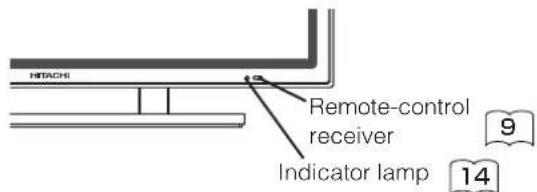
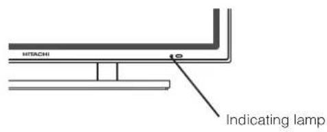
Indicating lamp
| Indicating lamp | Power status | Operating |
| Off Off | When the main power switch is set to OFF. | |
| Lights red | Off (standby) | When the main power switch is ON, and the OFF button on the remote control or the SUB POWER button on the underside of the front of the frame is OFF. |
| Lights green On | When the main power switch is ON, and the ON button on the remote control or the SUB POWER button on the underside of the front of the frame is ON. | |
| Lights orange | Off (standby) | When the main power switch is ON, and the ON button on the remote control or the SUB POWER button on the underside of the front of the frame is ON.However, the state in POWER SAVE mode |
When the indicating lamp lights in orange or the message "NO SYNC SIGNAL", "POWER SAVE" or "OUT OF FREQUENCY" appears on the screen, there is something unusual about the status of reception. See "POWER SAVE MODE" or "Symptoms That
Seemingly Appear to be Failures." 25 27
TIPS
- Avoid repeatedly turning the monitor on and off at short time intervals. Failures might result from such operation.
- Turn off the main power switch before leaving the monitor out of use for an extended period of time.
- If a power failure occurs while the main unit is running, it would be powered on upon recovery from the failure. Turn off the unit main power switch before leaving the main unit.
OPERATING INSTRUCTIONS (continued)


Input Switching
- Input can be switched by pressing the RGB1, RGB2, VIDEO 1 or VIDEO 2 buttons of the remote control.
- Input can be switched in the sequence of RGB1 → RGB2 → VIDEO 1 → VIDEO 2 by pressing the INPUT SELECT button of the monitor.
When INPUT SELECT is pressed:

flowchart
graph TD
    A["RGB1"] --> B["RGB2"]
    B --> C["VIDEO1"]
    C --> D["VIDEO2"]
    style A fill:#f9f,stroke:#333
    style B fill:#f9f,stroke:#333
    style C fill:#ccf,stroke:#333
    style D fill:#ccf,stroke:#333
- If the video unit is not installed, you cannot switch to VIDEO1 and VIDEO2.
- When the same signal is input to RGB1 and RGB2, the phases may be slightly misaligned. This is not a malfunction. In such case, please change one refresh rate (Vertical frequency 31) of the apparatus to be used.
Volume Adjustment
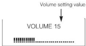
The volume can be adjusted by pressing the VOL+ and VOL- buttons of the remote control (or the ▲ and ▼ volume buttons of the monitor unit) while the on-screen display system is not being displayed.

Adjustment status guide display
- When a button is pressed, the volume adjustment status guide will be displayed.
- The volume will increase when the VOL+ (or ▲) button is pressed while the guide is being displayed.
- The volume will decrease when the VOL- (or ▼) button is pressed while the guide is being displayed.
• The volume can also be adjusted with the on-screen display system. 19
Audio Mute
The audio volume can be temporarily lowered to the mute volume level by pressing the MUTE button of the remote control.
Adjustment status guide display (The display color will change to pink.)
- When a button is pressed, the word MUTE (in pink) and the volume adjustment status guide will be displayed.
- The volume setting can be lowered by pressing the VOL- button while the audio is muted.
- The muting can be cancelled by pressing the VOL+ button while the audio is muted.
- When audio is muted with the on-screen display system, the volume setting can be adjusted. 19
When the MUTE button of the remote control is pressed again, muting will be canceled, the volume display (blue) will appear and sound will be output.
OPERATING INSTRUCTIONS (continued)
natural_image
Pure technical diagram showing a ladder with a horizontal support and an arrow indicating force or direction (no text or symbols)
SIZE button

Size Switching
Each time the SIZE button of the remote control or the monitor is pressed, the screen display size (or display area) will change in sequence and the status will be displayed at the bottom of the screen.
• During RGB signal input

- Some types of signals may not be able to switch as desired. * VGA and W-VGA only
• During VIDEO signal input
(when the optional video unit is attached)

- Depending on the type of signal, in some cases it may not be possible to switch the size, or switching to some sizes may not be possible.
<
Displaying Two Screens
If the PinP button on the remote control is pressed when the optional video unit is installed, two screens will display.
Activating the P-in-P mode from the RGB input screen
Pressing the PinP button one time will display two screens.
• The speaker icon can be shifted left and right by pressing the
and SELECT buttons; the audio of the video will be output from the side on which the speaker icon is located.
- The sub-screen can be selected with the VIDEO1 and VIDEO2 buttons from the status shown in the diagram to the right.
- Pressing the PinP button again will cancel the two screen display.
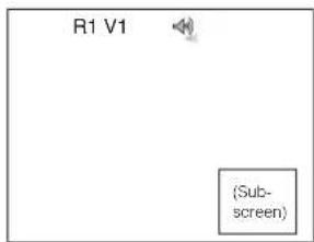
V1: Displays the VIDEO input signal of the sub-screen.
Activating the P-in-P mode from the video input screen
Pressing the PinP button one time will display two screens.
• The speaker icon can be shifted left and right by pressing the and
▶ SELECT buttons; the audio of the video will be output from the side on which the speaker icon is located.
- Pressing the PinP button again will increase the size of the screen.
- Pressing the PinP button once again will cancel the two screen display.
| V1 V2 | |
Refer to two screen table 25
TIPS
- Even if the input of the horizontal / vertical synchronizing signal (or video signal) stops in the two screen display, the mode will not change to power save mode.
- Please be careful since image retention will occur if display is left in a two screen display state for a long period of time.
Input Signal Screen Display
The input signal status can be displayed on the screen by pressing the RECALL button of the remote control.
• The display will go out in approximately 3 seconds.
![VIDEO VIDEO2 [COMPONENT] Input terminal name RGB RGB1 [RGB] H : 46.5kHz V : 60Hz Input horizontal frequency Input vertical frequency](/content/2026/05/1085401/images/a06c9ccdcb2b5aa9f61c98ad36f4385fcfd2d190fd92b0e11039e442ed37e97d.jpg)
OPERATING INSTRUCTIONS (continued)

Automatic Adjustment of Screen Position and the Clock
Adjustment of the screen to a position suitable for the video and the clock adjustment can be performed automatically by pressing the AUTO button of the remote control.
CAUTIONS
Perform this adjustment for each input (RGB1 or RGB2) and for each signal.
* Depending on the signal, satisfactory adjustment may not be possible in some cases. In such case, adjust by referring to the Display Menu item.
Independent Operation of Multiple Monitors (ID No)
Setting the ID No. of the remote control allows separate control of up to a maximum of seven monitors. Remote control ID No. 2 (initially ID no. 1) can be set by pressing the ID SET button for 2 sec. or more while holding down the ID button. The number will be incremented (2…6→7→1→2) when this button pressed continuously.
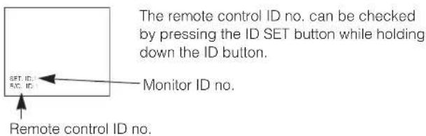
The ID remote control is operated by pressing the various buttons while holding down the ID button; Operation is possible only when the remote control and monitor ID nos. are the same.
- The remote control can be operated normally by pressing the various remote control buttons without holding down the ID button.
- Set the monitor using the ID No. of OTHER MENU. 23
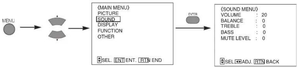
Using the Menu Screen (On-screen display system)
When the MENU button is pressed, the adjustment menu screen will be displayed; from there, video adjustment and setting is possible by using the SELECT button, ADJUST button and ENTER button.
- Refer to 18 - 23 concerning the adjustment items and the settings.
Example: Selecting the Picture screen
- Press the MENU button to display the Main Menu screen.

(MAIN MENU)
PICTURE
SOUND
DISPLAY
FUNCTION
OTHER
SEL. ENT ENT. RTN END
- Press the ENTER button to display the Picture Menu screen. (Use the ▲ and SELECT buttons to select other items.)

《PICTURE MENU》1/2
OPERATE MODE : NORMAL
CONTRAST : 127
BRIGHTNESS : 0
COLOR : 0
TINT : 0
ENHANCER : LOW
FILTER : OFF
RESET
SEL. ENT ENT. RTN BACK
- Use the ▲ and SELECT buttons to select the item to be adjusted and then use the ◀ and ADJUST buttons to adjust (example: COLOR).

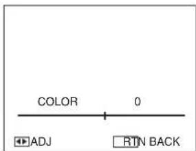
- Press the RETURN button to return to the previous screen.
- If there is no operation for a period of one minute, the Adjustment Menu screen will be closed automatically.
OPERATING INSTRUCTIONS (continued)
PICTURE MENU
(This function can only be used when the optional video unit has been inserted.)

flowchart
graph TD
    A["MENU"] --> B["《MAIN MENU》"]
    B --> C["《PICTURE MENU》 1/2"]
    C --> D["OPERATE MODE : NORMAL"]
    D --> E["CONTRAST : 127"]
    E --> F["BRIGHTNESS : 0"]
    F --> G["COLOR : 0"]
    G --> H["TINT : 0"]
    H --> I["ENHANCER : LOW"]
    I --> J["FILTER : OFF"]
    J --> K["RESET"]
    K --> L["SEL. ENT ENT. RTNBACK"]
    L --> M["《PICTURE MENU》 2/2"]
    M --> N["MODE : PC"]
    N --> O["GAMMA : 2.2"]
    O --> P["VIDEO LEVEL : 0.7V"]
    P --> Q["COLOR TEMP. : COOL"]
    Q --> R["R-GAIN : 255"]
    R --> S["G-GAIN : 255"]
    S --> T["B-GAIN : 255"]
    T --> U["SEL. ADJ. RTNBACK"]
    U --> V["RGB"]
    V --> W["ENTER"]
VIDEO

| Selected characters Setup hint | ▶ | ||
| OPERATE MODE | NORMAL↔ LIFE EXTEN.1↔ LIFE EXTEN.2↑ | By controlling the brightness of a screen, power consumption can be reduced or degradation of a panel can be mitigated. The order of effectiveness in reducing power consumption and reducing panel degradation is LIFE EXTEN.2 > LIFE EXTEN.1 > NORMAL. | |
| CONTRAST | Narrows the gap between brightness and darkness. | Broadens the gap between brightness and darkness. | Adjust for maximum visibility to suit the ambient brightness. Cannot be used when LIFE EXTEN1, 2 are selected. |
| BRIGHTNESS | Black is subdued for increasedoverall darkness. | Black is set off for increased overall brightness. | Adjust to prevent black from spreading across the screen. |
| COLOR | Lightens colors. Darkens colors. | Adjust for desired density, somewhat for lighter colors for a natural look. | |
| TINT | Enhances red and weakens green. | Enhances green and weakens red. | Adjust for a nice looking skin color. |
| ENHANCER | OFF↔ LOW↔ MID↔ HIGH↑ | Sets the clarity of small details to the desired level. | |
| FILTER | OFF ON | Only displayed for RGB signals. Turn ON when concerned about screen flicker. | |
| RESET | The original factory settings can be restored by pressing the ENTER button. | ||
| MODE | PC MOVIE | Set to MOVIE when viewing moving images on a personal computer. | |
| GAMMA | 2.2 2.8 | Normally set to 2.2. | |
| VIDEO LEVEL | 0.7 1.0 | Normally set to 0.7 V. If white is found to spread across the screen, set to 1.0 V. | |
| COLOR TEMP. | COOL↔ NORM↔ WARM↔ USER↑ | Normally set to COOL. | |
| R-GAIN | Red is weakened. Red is strengthened. | Sets the color adjustment selected by the user with COLOR TEMP..USER mode takes effect automatically when an attempt is made to set a gain. | |
| G-GAIN | Green is weakened. Green is strengthened. | ||
| B-GAIN | Blue is weakened. Blue is strengthened. | ||
OPERATING INSTRUCTIONS (continued)
PICTURE MENU (continued)
| Selected characters Setup hint | ▶ | ||
| SHARPNESS | Picture is soft Picture is sharp | In general, position is in the center and shift to the minus (-) side when a softer effect is desired. | |
| VIDEO PICTURE | NORMAL SOFT | Use SOFT when DVD, video and other images become harsh or picture noises on the screen is evident. Use NORMAL as standard. | |
| CONTRAST MODE | 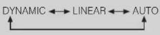 | DYNAMIC:Emphasizes the differences between video shadings to improve the feeling of contrast.LINEAR : The gradation of an image is reproduced as faithfully as possible.AUTO:Detects image brightness and automatically adjusts for natural brightness. | |
| BLACK STRETCH |  | Adjusts the black level compensation. | |
| LTI | Adjusts the sharpness of the brightness signal. | ||
| CTI | Adjusts the sharpness of the color signal. | ||
| YNR |  | Performs brightness signal noise reduction. Turn up to reduce noise. | |
| CNR | Performs color signal noise reduction. Turn up to reduce noise. | ||
| 3D COMB | ON OFF | Set to OFF when video and other images appear unnatural. Set to ON for normal use. Only an NTSC composite signal input is effective. It cannot choose at the time of a component signal (VIDEO 2). | |
| FILM MODE | OFF ON | ON:Automatically detects the movie film material and faithfully reproduces the original film image. Set to ON normally.OFF:Set to OFF when switching between images does not appear natural. | |
| LINE INTP. | OFF ON Set to ON when using | 3-D video disks. Set to OFF normally. | |
: This function can only be used when the optional video unit has been inserted.
SOUND MENU
flowchart
graph LR
    A["MENU"] --> B["AND"]
    B --> C["MAIN MENU"]
    C --> D["EXTER"]
    D --> E["(SOUND MENU)"]
    E --> F["VOLUME: 20"]
    E --> G["BALANCE: 0"]
    E --> H["TREBLE: 0"]
    E --> I["BASS: 0"]
    E --> J["MUTE LEVEL: 0"]
    E --> K["SEL: ENT. RTN END"]
| Selected characters Setup hint | ▶ | ||
| VOLUME | Turns down the volume. Turns up the volume. Adjust for the desired sound volume. | ||
| BALANCE | Suppresses right-side sound. Suppresses left-side sound. Adjust to taste. | ||
| TREBLE | Suppresses treble. Enhances treble. Adjust to taste. | ||
| BASS | Suppresses bass. Enhances bass. Adjust to taste. | ||
| MUTE LEVEL | Turns down the sound volume. Minimum 0. | Turns up the sound volume. Maximum pre-mute sound volume. | Varies the sound volume when the MUTE button is pressed. |
OPERATING INSTRUCTIONS (continued)
DISPLAY MENU

flowchart
graph TD
    A["MENU"] --> B["PARTICULAR"]
    B --> C["MAIN MENU"]
    C --> D["PICTURE"]
    C --> E["SOUND"]
    C --> F["DISPLAY"]
    C --> G["FUNCTION"]
    C --> H["OTHER"]
    H --> I["SEL. ENT ENT. RTNEND"]
    I --> J["ENTER"]
    J --> K["RGB"]
    K --> L["《DISPLAY MENU》 1/2"]
    L --> M["AUTO ADJUST"]
    M --> N["V.POSITION : 0"]
    M --> O["H.POSITION : 0"]
    M --> P["CLOCK : 0"]
    M --> Q-PHASE : 0
    M --> R["RESET"]
    R --> S["SEL. ADJ. RTN BACK"]
    S --> T["《DISPLAY MENU》 2/2"]
    T --> U["DISPLAY SIZE : FULL"]
    T --> V["SIDE AREA : GRAY"]
    T --> W["WIDE MODE : OFF"]
    T --> X["SEL. ADJ. RTN BACK"]
(This function can only be used when the optional video unit has been inserted.)
VIDEO
(DISPLAY MENU)
DISPLAY SIZE :: FRANORAMA
SIDE AREA : GRAY
V. POSITION : 0
SEL. ADJ. RTN BACK
| Selected characters Setup hint | ◄ | ► | Setup hint |
| AUTO ADJUST* | Automatic regulation is started with the ENTER button. | V. POSITION, H.POSITION, CLOCK, and PHASE are adjusted automatically. It is displayed as "ADJUSTMENT" during automatic regulation. | |
| V.POSITION | Moves down the vertical position. | Moves up the vertical position. | Adjust the vertical display position. |
| H.POSITION | Moves the horizontal position to left. | Moves the horizontal position to right. | Adjust the left-side display position. |
| CLOCK | Reduces the dot clock frequency (shrinks the right side). | Increases the dot clock frequency (expands the right side). | Adjust for maximum character clarity. |
| PHASE | Slows the dot clock phase (shifts slightly to left). | Advances the dot clock phase (shifts slightly to right). | Adjust for clear character visibility. |
| RESET | The original factory settings can be restored by pressing the ENTER button. | ||
| DISPLAY SIZE | RGB | FULL displays images on the full screen. Convenient for grasping entire images.* VGA and W-VGA only | |
| →FULL ↔ZOOM1 ↔ZOOM2 ↔NORM ↔REAL* ↔ZOOM3 | |||
| VIDEO | Select in accordance with the image software aspect ratio (horizontal to vertical ratio). | ||
| FULL ↔4:3 ↔PANORAMA ↑MOVIE2 ↔MOVIE1 | |||
| SIDE AREA | GRAY BLACK Sets the color of black outside the display screen | Select 4:3 is used parts outside the display screen when 4:3 is used. | |
| WIDE MODE** | OFF ON WIDE VGA display only ON | WIDE VGA display only. | |
| V.POSITION | Moves down the vertical position. | Moves up the vertical position. | Adjust the vertical position when captions are missing in PANORAMA / MOVIE1 / MOVIE2. |
* Depending on the type of signal displayed, displays may not be optimized through automatic adjustment. Apply MANUAL ADJUST to optimize them.
* 1080/60i signal doesn't exit the display of AUTO ADJUST. Apply MANUAL ADJUST in this case.
** When WIDE MODE is set to ON, the display area mode becomes FULL and switching of the size is not possible.
OPERATING INSTRUCTIONS (continued)
DISPLAY MENU (continued)
Display area selection diagram (RGB input)
| Resolution Full | display Circular display | |||||
| Display FULL | NORMAL REAL ZOOM1 ZOOM2 ZOOM3 | |||||
| 640 X 480 (VGA) |  |  |  |  | 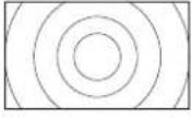 |  |
| 800 X 600 (SVGA) | ||||||
| 1024 X 768 (XGA) | * VGA and W-VGA only | |||||
| 1280 X 1024 (SXGA) | ||||||
| 1600 X 1200 (UXGA) | ||||||
Processes such as compression (thinning) and expansion are performed for the above signal display. Because of this, there is a possibility that flicker may become noticeable on ZOOM (1 \~ 3) depending on the display contents. If this occurs, turning the FILTER ON 18 can reduce the flicker.
TIPS
- Composite / S signal (video1 input) and component (576i, 480i, 480p) signal applicable for all size modes.
- For component (HD3: 1035i, 1080i, 720p) signals, the display mode is not selectable.
Display size selection diagram
(This function can only be used when the optional video unit has been inserted.)
| When you want to | Set the display size to | Input signal Display screen Remarks | ||
| Play a 4:3 image in a 16:9 screen faithfully. | 4 : 3 |  (4:3 signal) (4:3 signal) |  | Blanking occurs on both sides. |
| Play a 4:3 image in a 16:9 screen with the height and width of the middle of the screen enlarged on equal scales and with both sides appearing somewhat enlarged. | PANORAMA(Panoramic) |  | ||
| The 16:9 VISTA size image in the 4:3 Image is faithfully reproduced on the 16:9 screen. | MOVIE1 | 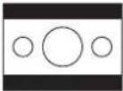 (Vista) (Vista) | 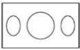 | • The 4:3 image is called a letterbox image.• In some cases, some slight blanking may remain at the top and bottom. |
| The 21:9 Cinema size image in the 4:3 Image is expanded vertically on the 16:9 screen. | MOVIE2 |  (Cinema) (Cinema) | 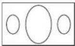 | In some cases, some slight blanking may remain at the top and bottom. |
| Play a 4:3 image faithfully in a 16:9 screen in the standard vertical size and horizontally squeezed.* | FULL |  (Squeez) (Squeez) | 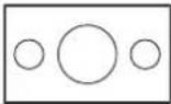 | * An image with an aspect ratio of 16:9 shrunk horizontally to 4:3 to display in a 4:3 screen |
OPERATING INSTRUCTIONS (continued)
DISPLAY MENU (continued)
TIPS
Using a wide-screen monitor
- This monitor has a screen mode selection feature. If an incompatible screen mode is selected to play certain software, such as a TV program, the image would appear different from the original. Take this into consideration when making screen mode choices.
- Use of this monitor in its enlarged display mode with the wide feature enabled in coffee shops, hotels and other establishments for commercial or pubic viewing purposes could infringe on the copyright holder's right protected by Copyright Law.
- When a normal 4:3 image is displayed over the entire screen in the PANORAMA mode, not the Wide mode, parts of the periphery of the image may disappear and/or appear distorted in some cases. Use the 4:3 mode to view images, which were created in 4:3 mode. This mode allows 4:3 content to be viewed without picture distortion.
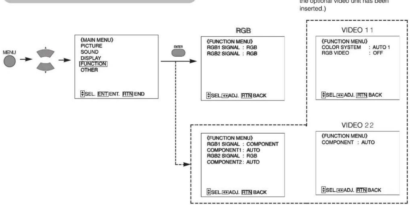
FUNCTION MENU
flowchart
graph TD
    A["MENU"] --> B["PARTICULAR"]
    B --> C["MAIN MENU"]
    C --> D["PICTURE"]
    C --> E["SOUND"]
    C --> F["DISPLAY"]
    C --> G["FUNCTION"]
    C --> H["OTHER"]
    C --> I["SEL. ENT. ENT. RTN END"]
    I --> J["RGB"]
    J --> K["FUNCTION MENU"]
    K --> L["RGB1 SIGNAL : RGB"]
    K --> M["RGB2 SIGNAL : RGB"]
    K --> N["SEL. ADJ. RTN BACK"]
    J --> O["VIDEO 11"]
    O --> P["FUNCTION MENU"]
    P --> Q["COLOR SYSTEM : AUTO 1"]
    P --> R["RGB VIDEO : OFF"]
    O --> S["VIDEO 22"]
    S --> T["FUNCTION MENU"]
    T --> U["COMPONENT : AUTO"]
    S --> V["SEL. ADJ. RTN BACK"]
    J -.-> W["ENTER"]
    W -.-> X["VIDEO 22"]
| Selected characters Setup hint | ▶ | ||
| RGB1 SIGNAL(RGB2 SIGNAL) | RGB COMPONENT | Sets to the signal output of the device to be connected to RGB I and RGB 2 jacks. | |
| COMPONENT(COMPONENT1, 2) | AUTO←→YCSCR←→YPBPR←→MUSE↑ | Setup matching the color matrix format of the signal to be input. | |
| COLOR SYSTEM | AUTO1←→NTSC←→PAL←→SECAM↑→N-PAL←→M-PAL←→4-NTSC← | Switch the color system to suit the input system in video input mode VIDEO1.• Normally, set to AUTO1. The input signal system will be automatically recognized to display input images on the screen (NTSC, PAL, NTSC4.43).• If the input signal contains much noise or has a low level at AUTO1 and the operation is found erratic, set to match the input system. | |
| RGB VIDEO | OFF ON | Compatible with European standard SCART signals. Inputs composite signals of video equipment to composite terminal and RGB signals of video equipment to connect R output to PB (CB) terminal, G output to Y terminal and B output to PB (CB) terminal. Normally set to OFF.* Cannot switch to VIDEO2 when ON is selected. | |
: This function can only be used when the optional video unit has been inserted.
OPERATING INSTRUCTIONS (continued)
OTHER MENU

flowchart
graph LR
    A["MENU"] --> B["MAIN MENU"]
    B --> C["OTHER"]
    C --> D["SEL. ENT ENT. RTN END"]
    E["ENTER"] --> F["《OTHER MENU》"]
    F --> G["AUTO DISPLAY : ON"]
    F --> H["OFF TIMER : OFF"]
    F --> I["LANGUAGE : ENGLISH"]
    F --> J["ID NO. : 1"]
    F --> K["ORBITER : OFF"]
    F --> L["Moving TIMER : 10MINITE"]
    F --> M["INVERSE : OFF"]
    F --> N["WHITE : OFF"]
    F --> O["SEL. ADJ. RTN BACK"]
| Selected characters Setup hint | ▶ | ||
| AUTO DISPLAY | Set to ON.Information is displayed when switching inputs and changing signals. | Set to OFF.Information is not displayed when switching inputs and changing signals. | Set to OFF when the display is not needed when switching signals. |
| OFF TIMER |  | This function automatically sets the power to standby status when the indicated time period has elapsed. | |
| LANGUAGE |  | ENGLISH is the factory setting. | |
| ID NO. |  | Assigns ID nos. to the monitors so that they can be controlled individually (up to 7 monitors can be controlled). | |
| ORBITER | OFF ON | Automatically moves the images to prevent image retention. The moving interval is set with the MOVING TIMER (1 - 60 min.). | |
| MOVING TIMER | Shortens the time interval. Extends the time interval. | ||
| INVERSE |  | Normally, set to the OFF mode. When 60 min. is set, the power will be set to standby status after 60 minutes have elapsed and the setting will be canceled. When a still image is displayed for an extended time, ON is then set and the same still image is again displayed, panel image retention is prevented with [INVERSE] ON or [WHITE] ON. Does not operate when there is no input signal. | |
| WHITE | |||
Automatic Store
Approximately 1 sec. after adjustment is completed, the adjustments will be recorded as shown in the table below.
| Menu Display Registration | condition | |
| PICTURE | OPERATE MODEVIDEO LEVEL3D COMB | |
| SOUND | VOLUMEBALANCETREBLEBASSMUTE LEVEL | |
| DISPLAY | SIDE AREARGRB1 SIGNAL | |
| FUNCTION | RGB2 SIGNALCOMPONENT1COMPONENT2COMPONENT(VIDEO2)COLOR SYSTEM | |
| OTHER | AUTO DISPLAYLANGUAGEID NO.ORBITERMOVING TIMERINVERSEWHITE | |
| PICTURE | CONTRASTBRIGHTNESSCOLORTINTGAMMACOLOR TEMP.CONTRAST MODEFILM MODE | Can register for every input function. |
| DISPLAY | DISPLAY SIZE | |
| Menu Display Registration condition | ||
| PICTURE | SHARPNESSVIDEO PICTUREBLACK STRETCHLTICTIYNRCNR | Can register for every input function in a video signal input. |
| DISPLAY V.P | POSITIONH.POSITIONCLOCKPHASE | Can register 1 group every signal mode. |
| PICTURE | ENHANCERFILTERMODE | |
| DISPLAYFUNCTION | WIDE MODERGB1 SIGNALRGB2 SIGNALCOMPONENT1COMPONENT2 | Can register settings every RGB1, RGB2 input (RGB mode). |
| PICTURE R-GAIN | G-GAINB-GAIN | Can register settings every RGB functions and video functions. |

: When the optional video unit has been inserted.
- The previously recorded items will be lost.
- The signal mode can be identified by the horizontal/vertical sync frequency and the sync signal polarity. Different signals with which all the elements are the same or similar will be handled as the same signal.
Signal Check
Changes in the signal status are displayed on the screen as they arise.
| Status Display | Action | |
| When AUTO DISPLAY is set to ON, the input signal is switched or when the RECALL button is pressed. | A guide is displayed for the input terminal and the horizontal and vertical sync frequency. | ____ |
| When the sync signal is no longer detected. | A guide displays NO SYNC SIGNAL, and POWER SAVE (for approx. 5 sec.)When the condition continues where the sync signal cannot be detected, indicator lamp of power source changes in orange and the mode switches to power save mode. | Recheck the personal computer power switch status and the connection status. |
| When the input signal does not match the monitor specifications or is in an unstable status. | A guide displays OUT OF FREQUENCY. | Recheck the input signal specifications.31-32 |
RGB

H : 46.5kHz V : 60Hz
VIDEO
(This function can only be used when the optional video unit has been inserted.)
VIDEO2
[COMPONENT]
POWER SAVE
OUT OF FREQUENCY
OTHERFEATURES (continued)
Power Save Mode
When the RGB input is selected
- When this unit is connected to a VESA DPMS computer, the Power Save (Off) mode can be set to be activated automatically when the computer is not being used to reduce power consumption by this unit.
| RGB sync signal | Horizontal Yes No Yes No | |||
| Vertical Yes Yes No No | ||||
| Video signal Active (normal display) Blank (no video) | ||||
| Operation mode On Off | ||||
| Indicating lamp Lights green Lights orange | ||||
| Power consumption 370W | 1W or less (100-120V)2W or less (200-240V) | |||
When the Video Input is selected
(This function can only be used when the optional video unit has been inserted.)
- When there is no video signal input, the power-saving system operates to reduce the power consumed by the sunit.
| Video signal Yes No | ||
| Screen display Active (normal display) Blank (no video) | ||
| Operation mode | On | Off |
| Indicating lamp | Lights green | Lights orange |
| Power consumption | 370W | 1W or less (100-120V)2W or less (200-240V) |
Returning to operating status
- Operate the personal computer, or press either the INPUT SELECT button of the main unit or the RGB//VIDEO button of the remote control.
* During two-screen displayed, the power save mode will not be activated even if the horizontal/vertical sync signal (or video signal) is no longer input.
TWO SCREEN TABLE
| Left screen\Right screen(Sub-screen) | RGB1PC input | RGB2PC input | RGB1Component | RGB2Component | VIDEO1(RGB VIDEO) | VIDEO2 | Notes |
| RGB1PC input | × | × | ○ | ○ | PC window | ||
| RGB2PC input | × | × | ○ | ○ | PC window | ||
| RGB1Component | × | × | ○ | ○ | Two screens | ||
| RGB2Component | × | × | ○ | ○ | Two screens | ||
| VIDEO1(RGB VIDEO) | × | × | × | × | ○(×) | Two screens | |
| VIDEO2 | × | × | × | × | ○ | Two screens |
IMAGE RETENTION OF PLASMA DISPLAY
There are different characteristics that result in panel image retention depending on how the plasma display is used. Situations and effective usage methods related to ghosting are provided below.
Image retention characteristics of a plasma display
The image retention phenomenon of a plasma panel occurs due to partial phosphor degradation arising from partial character and figure display.
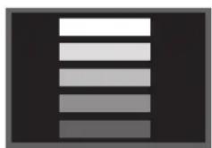
For example, when the character image as shown in Fig. A at the right is continuously displayed for a long period of time, the only part of the phosphor (Red, Green, Blue) that will degrade will be the color of the applicable character display portion. Consequently, when a while image is displayed on the entire screen as shown in Fig. a, the character marks displayed up to that time will become a color difference visible to the eye, but the phosphor will never burn.

■The degree of image retention is proportional to the brightness of the characters and figures displayed as well as the display time.
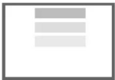
- The tendency of the phosphor is to degrade more the brighter the characters and figures are displayed. When images of figures with different levels of brightness, as shown in Fig. B, are continuously displayed for a long period of time, it becomes easier for image marks at locations when the brighter figures are displayed to be noticeable.
natural_image
Abstract grayscale vertical bar pattern on black background (no text or symbols)【Fig. B】

【Fig. b】
* The image retention images in this document are exaggerated for the purpose of explanation. The actual manner in which the image retention is seen differs depending on the operation time and brightness.
Methods to Reduce the Occurrence of Image Retention
- Lower the CONTRAST and BRIGHTNESS settings of the plasma display as much as possible.
A function is provided in the display that controls the brightness of the screen to reduce degradation of the panel. Using this function makes it possible to reduce image retention.
(Refer to OPERATE MODE (LIFE EXTEN. 1 OR LIFE EXTEN. 2 shown on 18)
- Set the plasma monitor to an "INVERSE" or "WHITE" display.
The occurrence of image retention when displaying images of identical patterns, such as static images, for long periods of time can be reduced by displaying a reversed color or completely white screen for about 1 \~ 2 hours after terminating the display. (Settings can be made using INVERSE AND WHITE of OTHER MENU shown on [23])
• Using in combination with moving images
Since the degradation of the fluorescent material progresses comparatively uniform for moving images, the occurrence of partial image retention can be controlled. We recommend to use in combination with moving images such as a DVD.
* Please be careful since image retention will occur if display is left in a two screen display state for a long period of time.
* Television broadcasts include images displayed for long periods of time in which the left and right or top and bottom of the image are cut and broadcast station name or time are displayed for a long period of time at the same portion of the screen. Image retention in these portions can be expected to occur, so please be aware.
NOTES
About screen defects
- High precision technology is used in the making of plasma panels but there may be dark spots (points that do not illuminate) and bright spots (points that are too bright) in some cases. These do not indicate a malfunction.
About residual images
- In some cases, residual images may remain after the short-term display of still images and another image is displayed, but these will disappear and return to normalcy. This is not a malfunction.
About the panel screen
- Plasma displays display images by means of electrical discharges inside the panel. Because of this, the temperature of the panel surface may rise in some cases. Also, plasma displays are made of finely processed glass. A reinforced glass filter is installed over the panel surface but avoid strong impact because there is still danger of glass breakage.
Symptoms That Seemingly Appear to be Failures
Make the checks suggested below depending on the symptoms observed. If the symptoms remain uncorrected, contact your dealer.

Customer servicing can be hazardous.
| Symptom Point to check See page | |||
| No picture with the power-indicating lamp off. |  | Check the way the power cable is connected.Press the power switch. | 1314 |
| The message "NO SYNC SIGNAL" or "POWER SAVE" is displayed.No picture with the power indicating lamp lights in orange. |   | No sync signal is detected.Check the way the signal cable is connected.Make sure that the switch of the computer, imaging equipment , etc., is turned on.Make sure the computer is not in the power-save mode.Check to see if the input selection matches the connection terminal. | 1112 |
| The message "OUT OF FREQUENCY" is displayed. |  | An input signal is not received normally.Check to see if the input signal matches the monitor specifications.Check the way the signal cable is connected. | 11123132 |
| The power indicating lamp is normally lit but no picture . |  | Check the contrast and brightness settings (adjust them for higher contrast and brightness).Check the way the signal cable is connected. | 111218 |
| The display image appears flowing slantwise.Text displayed across the screen appears vertically streaked, with the characters in vertical columns blurred. | 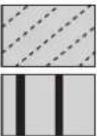 | Adjust the dot clock frequency and phase. (Adjust the dot clock frequency first, the dot clock phase next.) (RGB input) | 29 |
| Text displayed across the screen appears blurred.A fine pattern flickers when displayed on the screen. |  | Adjust the dot clock phase for the clearest viewing. (RGB input) | 29 |
| The remote controller does not work. | Check to see if the batteries are loaded in the remote controller in opposite direction.Check to see if the batteries in the remote controller are OK. | 9 | |
| The screen becomes dark and the images cannot be seen during VTR special playback (fast forward, rewind). | This sometimes occurs when a component output VTR such as the 480i is connected.This is not a malfunction; therefore, please take note that this may occur. When it does occur, change to composite output, or S1 (or S2) output. | - | |
| The display image does not come out by the SCART signal. | Check the way the signal cable is connected.Check the setup. | 1222 | |
| The temperature of the display panel surface is high. | The plasma display panel is lighting the phosphors by the discharge of internal radiation. In some cases, this may cause the temperature of the panel surface to increase. Please note that this is not a malfunction. | - | |
| There are locations on the screen that are different from the periphery (*).*Points that do not light, points with brightness different from that of the periphery, points with color different from that of the periphery, etc. | High-precision technology is used to manufacture the plasma display panel, However in some cases, there are minor defects in some parts of the screen. Please note that this is not a malfunction. | - | |
| Vertical stripes appear, depending on the screen contents. | The plasma display panel is lighting the phosphors by the discharge of internal radiation. Depending on the screen contents, in rare cases this may cause vertical stripes to appear because of failure to light. Please note that this is not a malfunction. | - | |
| Coarse horizontal stripes appear in FULL display. | Adjusting the phase will reduce the horizontal stripes.(RGB input) | - | |
| The display dims to make the picture invisible during special playback of a VCR (FF, REW). | This condition may occur when the unit is connected to a VCR with component output, such as 480i, but it is not a failure. But when it occurs, switch to composite output or S1 (S2) output). | - | |
| Flickering in the form of horizontal lines oscillating up and down.(PC INPUT MODE only) | If the direct frequency from the computer is below 85Hz, try a higher frequency (upper limit 85Hz). There may be a slight attenuation of the current image.Try turning the FILTER ON. For this case however, the vertical resolution will drop. | 18 | |
| The fan motor is noisy. | Use the fan that controls the temperature in the main body to lower the temperature of this unit. If the ambient air temperature increases, the fan will start, the RPMs will increase and motor noise will grow louder. This is not a malfunction though. | - | |
| The top of the monitor heats up. | When used for long periods of time, the top of the monitor may heat up. This is not a malfunction. | - | |
| Text characters are displayed with varying thicknesses. | The thicknesses of characters and lines may vary if images with a vertical resolution greater than 512 lines are displayed; however, this is not a malfunction. | - | |
TROUBLESHOOTING (continued)
Actions to Correct Abnormal Displays
Depending on the kind of system equipment used, images may not be displayed normally. In this case, make the adjustments suggested below.
| Symptom 1 | Text displayed across the screen appears vertically streaked, with some characters blurred (figure 1).The display image appears flowing (figure 2) (RGB input). | |
| Example | Figure 1 | 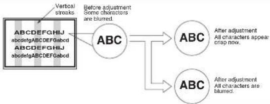 |
| Adjustment procedure | 1) Press the AUTO button on the remote control. | |
| When adjustment is not possible with AUTO ADJUST2) Press the MENU button. The Main Menu will be displayed.3) Press the▼ey of the SELECT button and select DISPLAY.4) Press the ENTER button. The Display Menu will be displayed.5) Press the▼ey and select CLOCK.(Display fine patterns as characters or a vertical striped pattern over the entire screen during clock adjustment.)6) Press the ▶ key and search for clear characters over the entire screen.7) Perform adjustment for symptom 2 below, when the characters are blurred on the entire screen. | ||
- The display image may be momentarily disturbed during clock adjustment but this is not a failure.
| Symptom 2 | Text displayed across the screen appears blurred in its entirety (figure 2).A fine pattern flickers when displayed on the screen (figure 3). | |
| Example | Figure 2 | Figure 3 |
| Adjustment procedure | 1) Press the AUTO button on the remote control. | |
| When adjustment is not possible with AUTO ADJUST2) Press the MENU button. The Main Menu will be displayed.3) Press the▼ey of the SELECT button and select DISPLAY.4) Press the ENTER button. The Display Menu will be displayed.5) Press the▼ey and select PHASE.(Display fine patterns as characters or a vertical striped pattern over the entire screen during PHASE adjustment.) | ||
| 6) Press ▷ to make the text appear clean across the screen. | 6) Press ▷ to make the text appear without flickering. | |
PRODUCT SPECIFICATIONS
Product specifications and designs are subject to change without notice.
| Panel | Display dimensions | Approx. 42 inches (922 mm (H), vertical 522 mm (V), diagonal 1059 mm) | |
| Resolution 1024 (H) x 1024 (V) pixels | |||
| Input signals | Input terminals | RGB input VIDEO input* | |
| RGB one-line two input terminals (D-sub 15-pin)RGB audio two-line two input terminals(3.5mm Stereo mini jack) | Video 1 video input terminal (RCA)Video 1 audio input terminals (left, right) (RCA)Video 1 S video input terminal (S)Video 2 video input terminals (Y) (Pb/Cb) (Pr/Cr) (RCA)Video 2 audio input terminals (left, right) (RCA) | ||
| Video signals | 0.7 V/1.0 Vp-p, analog RGB (Recommended Signal)1080/50i, 1080/60i | VIDEO input 1: NTSC, NTSC-4.43, M-PAL, PAL60, PAL,N-PAL, SECAMVIDEO input 2: 480/60i, 480/60p, 720/60p, 1080/60i, 1035/60i,576/50i, 576/50P, 1080/50i | |
| Sync signals | H/V separate, TTL level [2KΩ] | - | |
| H/V composite, TTL level [2KΩ] | - | ||
| Sync on green, 0.3 Vp-p [75Ω] | - | ||
| Video output Signal | - | Through output (RCA) of VIDEO1 input. | |
| Recommended Signal 31 modes | 16 modes 31 | 32 | |
| Audio output terminal 10W + 10W (6Ω) | |||
| Input power | AC100 - 120 / 200 - 240V(automatically selected) 3.7A / 2APower consumption 370W | ||
| External dimensions 1030 (W) x 636 (H)x 89 (D) (mm) (excluding the stand) | |||
| Mass 31kg (excluding the stand), 35kg (When mounted on optional stand.) | |||
| Ambient conditions | Temperature | Operating: 5°C to 35°C, Storage: 0°C to 40°C | |
| Relative humidity | Operating: 20% to 80%, Storage: 20% to 90% (non-condensing) | ||
- The monitor takes at least 30 minutes to attain the status of optimal picture quality.
* This function can only be used when the optional video unit has been inserted.
Signal Input
RGB terminal (D-sub 15-pin connector)
| Pin | Input signal |
| 1 | R. video (PR/CR) |
| 2 | G. video or sync on green (Y) |
| 3 | B. video (PB/CR) |
| 4 | No connection |
| 5 | No connection |
| 6 | R.GND (PR/CR, GND) |
| 7 | G.GND (Y, GND) |
| 8 | B.GND (PB/CR, GND) |
| 9 | No connection |
| 10 | GND |
| 11 | No connection |
| 12 | [SDA] |
| 13 | H. sync or H/V composite sync |
| 14 | V.sync. [V.CLK] |
| 15 | [SCL] |
( ) : With RGB component input

- When different kinds of input signals are simultaneously input to the monitor via a graphics board or the like, the monitor will automatically select the signals in the following priority order:
| Sync signal type Priority | |
| H/V separate sync. | 1 |
| H/V composite sync. | 2 |
| sync.on Green * | 3 |
*Even in the case of the recommended signals shown on the following page, there may be instances when correct display is not possible. In this case, use H/V separate sync, H/V composite sync.
PRODUCT SPECIFICATIONS (continued)
Signal Input (continued)
S-input connector pin specifications
| Pin Input signal | |
| 1 | Y |
| 2 Y-GND | |
| 3 | C |
| 4 C-GND | |
| Frame GND | |
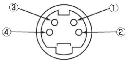
Recommended Signal List
The following are recommended for use with this moniter
RGB signal input (RGB1 or RGB2 signal input)
| No. | Signal mode | Horizontal frequency (kHz) | Dot clock frequency (MHz) | Remarks | ||
| Signal Name | Resolution | Vertical frequency (Hz) | ||||
| 1 | VGA640 X 480 | 640 X 400 70.08 31.47 25.18 | ||||
| 2 | 59.94 31.47 25.18 | |||||
| 3 | W-VGA 864 | X 480 59.94 31.47 34.24 | * WIDE MODE correspondence | |||
| 4 | 640 X 480 | 640 X 480 72.81 37.86 31.50 | ||||
| 5 | 75.00 37.50 31.50 | |||||
| 6 | 640 X 480 | 85.01 43.27 36.00 | ||||
| 7 | 800 X 600 | 56.25 35.16 36.00 | ||||
| 8 | 800 X 600 | 60.32 37.88 40.00 | ||||
| 9 | 800 X 600 | 72.19 48.08 50.00 | ||||
| 10 | 800 X 600 | 75.00 46.88 49.50 | ||||
| 11 | 800 X 600 | 85.06 53.67 56.25 | ||||
| 12 | 1024 X 768 | 60.00 48.36 65.00 | ||||
| 13 | 1024 X 768 | 70.07 56.48 75.00 | ||||
| 14 | 1024 X 768 | 75.03 60.02 78.75 | ||||
| 15 | 1024 X 768 | 85.00 68.68 94.50 | ||||
| 16 | 1152 X 864 | 75.00 67.50 108.00 | ||||
| 17 | 1280 X 1024 | 60.02 63.98 108.00 | ||||
| 18 | 1280 X 1024 | 75.03 79.98 135.00 | ||||
| 19 | 1280 X 1024 | 85.02 91.15 157.50 | ||||
| 20 | 1600 X 1200 | 60.00 75.00 162.00 | ||||
| 21 | 1600 X 1200 | 75.00 93.75 202.50 | ||||
| 22 | 1600 X 1200 | 85.00 | 106.25 | 229.50 | ||
| 23 | 832 X 624Macintosh | 640 X 480 66.67 35.00 30.24 | ||||
| 24 | 74.55 49.72 57.28 | |||||
| 25 | 1024 X 768 | 74.93 60.24 80.00 | ||||
| 26 | 1152 X 870 | 75.06 68.68 100.00 | ||||
| 27 | 1080 / 60i | 1080i | 60.00 | 33.75 | 74.25 | Only in the case of H/V separate sync |
| 28 | 1080 / 50i | 1080i | 50.00 | 28.13 | 74.25 | |
| 29 | 720P | 720P | 60.00 | 45.00 | 74.25 | |
| 30 | W-XGA | 1280 X 768 | 59.833 | 47.986 81.00 | ||
| 31 | 1280 X 768 | 69.997 | 56.137 | 94.760 | ||
PRODUCT SPECIFICATIONS (continued)
Recommended Signal List (continued)
With Composite/S-video Input(VIDEO1 input).
This function can only be used when the optional video unit has been inserted.
| No. | Signal mode | Horizontal frequency (kHz) | Dot clock frequency (MHz) | Remarks | ||
| Signal Name | Resolution | Vertical frequency (Hz) | ||||
| 1 | NTSCNTSC-4.43M-PALPAL60 | 525 59.94 15 | 73 | — | ||
| 2 | PALN-PALSECAM | 625 50.00 15 | 63 | — | ||
With R, G, B Video input (VIDEO1 and VIDEO2 input).
This function can only be used when the optional video unit has been inserted.
| No. | Signal mode | Horizontal frequency (kHz) | Dot clock frequency (MHz) | Remarks | ||
| Signal Name | Resolution | Vertical frequency (Hz) | ||||
| 1 SCART | NTSCPAL | 59.9450.00 | 15.73415.625 | — | European Standard. | |
With component input (VIDEO2 input)
This function can only be used when the optional video unit has been inserted.
| No. | Signal mode | Horizontal frequency (kHz) | Dot clock frequency (MHz) | Remarks | ||
| Signal Name | Resolution | Vertical frequency (Hz) | ||||
| 1 480/60i 480 59.94 | 15.73 | — | ||||
| 2 576/50i 576 50.00 | 15.63 | — | ||||
| 3 576/50p 576 50.00 | 31.26 | — | ||||
| 4 480/60p 480 59.94 | 31.47 | — | ||||
| 5 720/60p 720 59.94 | 44.96 | — | ||||
| 6 1080/50i 1080 50.00 | 28.13 | — | ||||
| 7 1080/60i 1080 60.00 | 33.75 | — | ||||
| 8 1035/60i 1035 60.00 | 33.75 | — | ||||
- The type of video board or connecting cable used may not allow for correct displays adjustment of H.POSITION, V.POSITION, CLOCK and PHASE.
- The monitor may fail to display an animation image correctly when a signal having a vertical frequency of 85Hz or higher is input to it.
- The monitor differentiates the signal modes according to the horizontal and vertical frequencies and the horizontal and vertical sync signal polarities. Note that different signals having all these elements alike may be handled as the same signal.
- Displaying images with more than 512 lines of vertical resolution at Full display (compressed display) can result in the interpolation of stripes.