Vigor VAP902 - Router Draytek - Free user manual and instructions
Find the device manual for free Vigor VAP902 Draytek in PDF.


User questions about Vigor VAP902 Draytek
0 question about this device. Answer the ones you know or ask your own.
Ask a new question about this device
Download the instructions for your Router in PDF format for free! Find your manual Vigor VAP902 - Draytek and take your electronic device back in hand. On this page are published all the documents necessary for the use of your device. Vigor VAP902 by Draytek.
USER MANUAL Vigor VAP902 Draytek
natural_image
White wireless router with two white antennas against a red background (no visible text or symbols on the device body)Your reliable networking solutions partner
User's Guide
VigorAP 902
802.11ac Access Point
User's Guide
Version: 1.5
Firmware Version: V1.1.7.1
Date: June 22, 2016
Intellectual Property Rights (IPR) Information
Copyrights
© All rights reserved. This publication contains information that is protected by copyright. No part may be reproduced, transmitted, transcribed, stored in a retrieval system, or translated into any language without written permission from the copyright holders.
Trademarks
The following trademarks are used in this document:
● Microsoft is a registered trademark of Microsoft Corp.
● Windows, Windows 95, 98, Me, NT, 2000, XP, Vista, 7 and Explorer are trademarks of Microsoft Corp.
● Apple and Mac OS are registered trademarks of Apple Inc.
● Other products may be trademarks or registered trademarks of their respective manufacturers.
Safety Instructions and Approval
Safety Instructions
● Read the installation guide thoroughly before you set up the modem.
- The modem is a complicated electronic unit that may be repaired only by authorized and qualified personnel. Do not try to open or repair the modem yourself.
● Do not place the modem in a damp or humid place, e.g. a bathroom.
● The modem should be used in a sheltered area, within a temperature range of +5 to +40 Celsius.
- Do not expose the modem to direct sunlight or other heat sources. The housing and electronic components may be damaged by direct sunlight or heat sources.
- Do not deploy the cable for LAN connection outdoor to prevent electronic shock hazards.
- Keep the package out of reach of children.
- When you want to dispose of the modem, please follow local regulations on conservation of the environment.
Warranty
We warrant to the original end user (purchaser) that the modem will be free from any defects in workmanship or materials for a period of one (1) year from the date of purchase from the dealer. Please keep your purchase receipt in a safe place as it serves as proof of date of purchase. During the warranty period, and upon proof of purchase, should the product have indications of failure due to faulty workmanship and/or materials, we will, at our discretion, repair or replace the defective products or components, without charge for either parts or labor, to whatever extent we deem necessary tore-store the product to proper operating condition. Any replacement will consist of a new or re-manufactured functionally equivalent product of equal value, and will be offered solely at our discretion. This warranty will not apply if the product is modified, misused, tampered with, damaged by an act of God, or subjected to abnormal working conditions. The warranty does not cover the bundled or licensed software of other vendors. Defects which do not significantly affect the usability of the product will not be covered by the warranty. We reserve the right to revise the manual and online documentation and to make changes from time to time in the contents hereof without obligation to notify any person of such revision or changes.
Be a Registered Owner
Web registration is preferred. You can register your Vigor modem via http://www.draytek.com.
Firmware & Tools Updates
Due to the continuous evolution of DrayTek technology, all modems will be regularly upgraded. Please consult the DrayTek web site for more information on newest firmware, tools and documents.
http://www.draytek.com
European Community Declarations
Manufacturer: DrayTek Corp.
Address: No. 26, Fu Shing Road, Hukou Township, Hsinchu Industrial Park, Hsinchu County, Taiwan 303 Product: VigorAP 902
DrayTek Corp. declares that VigorAP 902 is in compliance with the following essential requirements and other relevant provisions of R&TTE Directive 1999/5/EC, ErP 2009/125/EC and RoHS 2011/65/EU.
The product conforms to the requirements of Electro-Magnetic Compatibility (EMC) Directive 2004/108/EC by complying with the requirements set forth in EN55022/Class B and EN55024/Class B.
The product conforms to the requirements of Low Voltage (LVD) Directive 2006/95/EC by complying with the requirements set forth in EN60950-1.
This product is designed for 2.4GHz/5GHz WLAN network throughout the EC region and Switzerland with restrictions in France.
Federal Communication Commission Interference Statement
This equipment has been tested and found to comply with the limits for a Class B digital device, pursuant to Part 15 of the FCC Rules. These limits are designed to provide reasonable protection against harmful interference in a residential installation. This equipment generates, uses and can radiate radio frequency energy and, if not installed and used in accordance with the instructions, may cause harmful interference to radio communications. However, there is no guarantee that interference will not occur in a particular installation. If this equipment does cause harmful interference to radio or television reception, which can be determined by turning the equipment off and on, the user is encouraged to try to correct the interference by one of the following measures:
● Reorient or relocate the receiving antenna.
- Increase the separation between the equipment and receiver.
- Connect the equipment into an outlet on a circuit different from that to which the receiver is connected.
- Consult the dealer or an experienced radio/TV technician for help.
This device complies with Part 15 of the FCC Rules. Operation is subject to the following two conditions:
(1) This device may not cause harmful interference, and
(2) This device may accept any interference received, including interference that may cause undesired operation.
THE GRANTEE IS NOT RESPONSIBLE FOR ANY CHANGES OR MODIFICATIONS NOT EXPRESSLY APPROVED BY THE PARTY RESPONSIBLE FOR COMPLIANCE. SUCH MODIFICATIONS COULD VOID THE USER'S AUTHORITY TO OPERATE THE EQUIPMENT
You are cautioned that changes or modifications not expressly approved by the party responsible for compliance could void your authority to operate the equipment.
Please visit http://www.draytek.com for more information.




The antenna/transmitter should be kept at least 20 cm away from human body.
FCC RF Radiation Exposure Statement
- This Transmitter must not be co-located or operating in conjunction with any other antenna or transmitter.
- This equipment complies with FCC RF radiation exposure limits set forth for an uncontrolled environment. This equipment should be installed and operated with a minimum distance of 20 centimeters between the radiator and your body.
GPL Notice
This DrayTek product uses software partially or completely licensed under the terms of the GNU GENERAL PUBLIC LICENSE. The author of the software does not provide any warranty. A Limited Warranty is offered on DrayTek products. This Limited Warranty does not cover any software applications or programs.
To download source codes please visit:
http://gplsource.draytek.com
GNU GENERAL PUBLIC LICENSE:
https://gnu.org/licenses/gpl-2.0
Version 2, June 1991
For any question, please feel free to contact DrayTek technical support at support@draytek.com for further information.
Table of Contents
1
Introduction ....1
1.1 Introduction ...... 1
1.2 LED Indicators and Connectors 3
1.3 Hardware Installation 5
1.3.1 Wired Connection for PC in LAN 5
1.3.2 Wired Connection for Notebook in WLAN 6
1.3.3 Wireless Connection....7
1.3.4 PoE Connection....8
2
Network Configuration....9
2.1 Windows 7 IP Address Setup....9
2.2 Windows 2000 IP Address Setup....11
2.3 Windows XP IP Address Setup 12
2.4 Windows Vista IP Address Setup.... 13
2.5 Accessing to Web User Interface.... 14
2.6 Changing Password 15
2.7 Quick Start Wizard 16
2.7.1 Configuring 2.4GHz Wireless Settings – General 16
2.7.2 Configuring 2.4GHz Wireless Settings based on the Operation Mode 18
2.7.3 Configuring 2.4GHz Security Settings 25
2.7.4 Configuring 5GHz Wireless Settings 27
2.7.5 Configuring 5GHz Security Settings 28
2.7.6 Finishing the Wireless Settings Wizard 30
2.8 Online Status.... 31
3
Advanced Configuration....33
3.1 Operation Mode 34
3.2 LAN 35
3.2.1 General Setup.... 35
3.2.2 Port Control.... 38
3.3 Central AP Management 38
3.3.1 General Setup.... 38
3.3.2 APM Log 39
3.3.3 Function Support List.... 39
3.3.4 Overload Management 40
3.3.5 Status of Settings....41
3.4 General Concepts for Wireless LAN (2.4GHz/5GHz) 42
3.5 Wireless LAN Settings for AP Mode 44
3.5.1 General Setup....45
3.5.2 Security 48
3.5.3 Access Control.... 51
3.5.4 WPS.... 52
3.5.5 Advanced Setting.... 53
3.5.6 AP Discovery 53
3.5.7 WMM Configuration.... 54
3.5.8 Bandwidth Management 57
3.5.9 Airtime Fairness 58
3.5.10 Station Control 60
3.5.11 Roaming 61
3.5.12 Band Steering 63
3.5.13 Station List 67
3.6 Wireless LAN Settings for Station-Infrastructure Mode 69
3.6.1 General Setup.... 69
3.6.2 Site Survey 74
3.6.3 Statistics....75
3.6.4 WPS (Wi-Fi Protected Setup) 75
3.7 Wireless LAN Settings for AP Bridge-Point to Point/AP Bridge-Point to Multi-Point Mode .. 77
3.7.1 General Setup....77
3.7.2 Advanced Setting....80
3.7.3 AP Discovery 81
3.7.4 WDS AP Status 82
3.8 Wireless LAN Settings for AP Bridge-WDS Mode 83
3.8.1 General Setup.... 83
3.8.2 Security 88
3.8.3 Access Control....91
3.8.4 WPS....92
3.8.5 Advanced Setting....93
3.8.6 AP Discovery 93
3.8.7 WDS AP Status 94
3.8.8 WMM Configuration 95
3.8.9 Bandwidth Management....97
3.8.10 Airtime Fairness....98
3.8.11 Station Control.... 100
3.8.12 Roaming 101
3.8.13 Band Steering.... 103
3.8.14 Station List 107
3.9 Wireless LAN Settings for Universal Repeater Mode 109
3.9.1 General Setup.... 110
3.9.2 Security 114
3.9.3 Access Control.... 117
3.9.4 WPS 118
3.9.5 Advanced Setting.... 119
3.9.6 AP Discovery 119
3.9.7 Universal Repeater 121
3.9.8 WMM Configuration.... 123
3.9.9 Bandwidth Management.... 125
3.9.10 Airtime Fairness.... 126
3.9.11 Station Control 128
3.9.12 Roaming 129
3.9.13 Band Steering 131
3.9.14 Station List 135
3.10 Wireless LAN (5GHz) Settings for AP Mode.... 137
3.10.1 General Setup.... 137
3.10.2 Security 139
3.10.3 Access Control.... 142
3.10.4 WPS.... 143
3.10.5 Advanced Setting.... 144
3.10.6 AP Discovery 145
3.10.7 WMM Configuration.... 146
3.10.8 Bandwidth Management 147
3.10.9 Airtime Fairness.... 148
3.10.10 Station Control 150
3.10.11 Roaming 151
3.10.12 Station List 153
3.11 Wireless LAN (5GHz) Settings for Universal Repeater Mode.... 155
3.11.1 General Setup.... 155
3.11.2 Security 157
3.11.3 Access Control.... 161
3.11.4 WPS 162
3.11.5 Advanced Setting.... 163
3.11.6 AP Discovery 163
3.11.7 Universal Repeater 165
3.11.8 WMM Configuration.... 167
3.11.9 Bandwidth Management.... 169
3.11.10 Airtime Fairness.... 170
3.11.11 Station Control 172
3.11.12 Roaming 173
3.11.13 Station List 175
3.12 RADIUS Setting 177
3.12.1 RADIUS Server.... 177
3.12.2 Certificate Management 178
3.13 Applications 180
3.13.1 Schedule....180
3.13.2 Apple iOS Keep Alive 182
3.13.3 Temperature Sensor.... 183
3.14 Mobile Device Management 185
3.14.1 Detection.... 185
3.14.2 Policy 186
3.14.3 Statistics 186
3.15 System Maintenance.... 187
3.15.1 System Status.... 187
3.15.2 TR-069 189
3.15.3 Administrator Password.... 191
3.15.4 Configuration Backup 192
3.15.5 Syslog/Mail Alert 193
3.15.6 Time and Date 194
3.15.7 Management.... 195
3.15.8 Reboot System 196
3.15.9 Firmware Upgrade 196
3.16 Diagnostics.... 197
3.16.1 System Log.... 197
3.16.2 Speed Test 197
3.16.3 Traffic Graph.... 198
3.16.4 WLAN (2.4GHz) Statistics 198
3.16.5 WLAN (5GHz) Statistics 199
3.16.6 Station Statistics 200
3.17 Support Area 201
4
Applications....203
4.1 How to set different segments for different SSIDs in VigorAP 902.... 203
4.2 How to use VigorAP in Universal Repeater Mode? 207
5
Trouble Shooting....215
5.1 Checking If the Hardware Status Is OK or Not.... 215
5.2 Checking If the Network Connection Settings on Your Computer Is OK or Not ...... 216
5.3 Pinging the Modem from Your Computer 219
5.4 Backing to Factory Default Setting If Necessary 220
5.5 Contacting DrayTek.... 221
1
Introduction

Note: This is a generic International version of the user guide. Specification, compatibility and features vary by region. For specific user guides suitable for your region or product, please contact local distributor.
1.1 Introduction
Thank you for purchasing this VigorAP 902, the concurrent dual band wireless (2.4G/5G) access point offering high-speed data transmission. With this high cost-efficiency VigorAP 902, computers and wireless devices which are compatible with 802.11n/802.11a can connect to existing wired Ethernet network via this VigorAP 902, at the speed of 300Mbps.
Easy install procedures allows any computer users to setup a network environment in very short time - within minutes, even inexperienced users. Just follow the instructions given in this user manual, you can complete the setup procedure and release the power of this access point all by yourself!
VigorAP 902 also is a Power over Ethernet Powered Device which adopts the technology of PoE for offering power supply and transmitting data through the Ethernet cable.
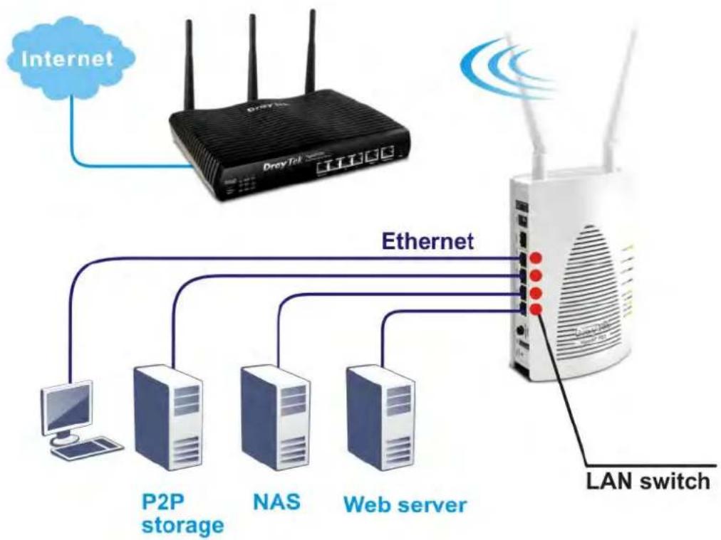
flowchart
graph TD
    A["Internet"] --> B["DreyTel"]
    B --> C["Ethernet"]
    C --> D["P2P storage"]
    C --> E["NAS"]
    C --> F["Web server"]
    C --> G["LAN switch"]
    style A fill:#f9f,stroke:#333
    style B fill:#ccf,stroke:#333
    style C fill:#cfc,stroke:#333
    style D fill:#fcc,stroke:#333
    style E fill:#fcc,stroke:#333
    style F fill:#fcc,stroke:#333
    style G fill:#fff,stroke:#333
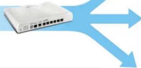
AP Management
The VigorAP 902 can operate in standalone mode for your office network or a classroom or a waiting room of some transportation terminals (e.g. ferry terminal, bus station, train station) or a clinic's waiting room; connected to your LAN and offering you with wireless access. If your network requires several VigorAP 902 units, to centrally manage and monitor them individually as a group will be expected. DrayTek central wireless management (AP Management) lets control, efficiency, monitoring and security of your company-wide wireless access easier be managed. Inside the web user interface, we call “central wireless management” as Central AP Management which supports mobility, client monitoring / reporting and load-balancing to multiple APs. For central wireless management, you will need a Vigor2860 or Vigor2925 series router; there is no per-node licensing or subscription required. With the unified user interface of Vigor2860 Combo WAN series and Vigor2925 Triple WAN series, the multiple deployment of VigorAP 902 can be clear at the first sight. For multiple wireless clients to apply the AP Load Balancing to the multiple APs, AP management will manage wireless traffic with smooth flow and enhanced efficiency.
WLAN Setting
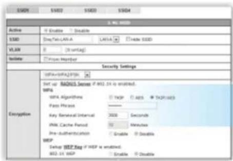
text_image
SMDI SMD2 SMD3 SMD4 Active If Enable Double SMDI (SepTetLAN-A LANSA) [ ] Hide SODD VLAN 0 [ ] Untag! Initiate Inque Member Security Settings Encryption Set up RANOS Server if MDD.5K is enabled. MIPS DATA Algorithms [ ] Hager [ ] APS [ ] TXAP/SDS Pass Phase [ ] Key Renewable Interval 3000 Seconds PWM Cache Period 50 Minutes Pre-authentication [ ] Enable [ ] Double WBP Setup WBP Key if WBP is enabled. MDD.5K WBP [ ] Enable [ ] DoubleVigor Router
text_image
IPB 14.00 IPB 14.00 IPB 14.00
AP Status
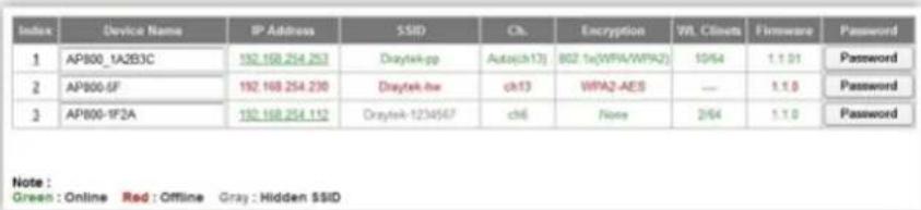
text_image
Index Device Name IP Address SSID Ch Encryption WIL Clients Firmware Password 1 APB00_1A2E3C 192.168.254.253 Draytek-pp Auto(ch13) 802 tx(WPA/WPA2) 10/64 1.1.01 Password 2 APB00-6F 192.168.254.230 Draytek-lw ch13 WPA2-AES --- 1.1.0 Password 3 APB00-1F2A 192.168.254.112 Draytek-1234567 ch6 None 2/64 1.1.0 Password Note: Green : Online Red : Offline Gray : Hidden $SID1.2 LED Indicators and Connectors
Before you use the Vigor modem, please get acquainted with the LED indicators and connectors first.
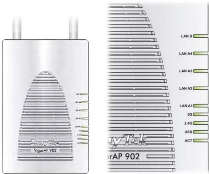
text_image
VigorAP 902 LAN B LAN A4 LAN A3 LAN A2 LAN A1 5G 2.4G USB ACT LAN B LAN A4 LAN A3 LAN A2 LAN A1 5G 2.4G USB ACT VigorAP 902| LED Status Explanation | ||
| Off The system is not ready or is failed. ACT | ||
| Blinking The system is ready and can work normally. | ||
| On A USB device is connected and active. USB | ||
| Blinking The data is transmitting. | ||
| 2.4G | On Wireless function is ready. | |
| Off Wireless function is not ready. | ||
| Blinking Data is transmitting (sending/receiving). | ||
| 5G | On Wireless function is ready. | |
| Off Wireless function is not ready. | ||
| Blinking Data is transmitting (sending/receiving). | ||
| LAN A1 - A4 | On A normal connection (rate with 100M/1000M) is through its corresponding port. | |
| Off LAN is disconnected. | ||
| Blinking Data is transmitting (sending/receiving). | ||
| LAN B | On A normal connection (rate with 100M/1000M) is through its corresponding port. | |
| Off LAN is disconnected. | ||
| Blinking Data is transmitting (sending/receiving). | ||
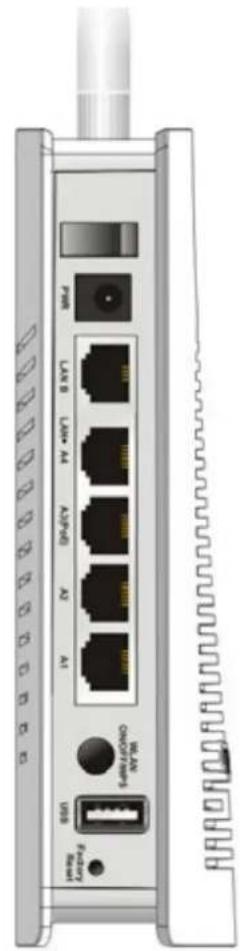
text_image
I/O I/O I/O I/O I/O I/O I/O I/O I/O I/O I/O I/O I/O I/O I/O I/O I/O I/O I/O I/O I/O I/O I/O I/O I/O I/O I/O I/O I/O I/O I/O I/O I/O I/O N/A N/A N/A N/A N/A N/A N/A N/A N/A N/A N/A N/A N/A N/A N/A N/A N/A N/A N/A N/A N/A N/A N/A N/A N/A N/A N/A N/A N/A N/A N/A N/A N/A N/A| Interface Description | |
| 0/1 | Power switch. |
 | PWR: Connector for a power adapter. |
| LAN B | Connector for xDSL / Cable modem (Giga level) or router. |
| LAN A4, A2, A1A3 (PoE) | Connector for xDSL / Cable modem (Giga level) / computer or router.LAN A3 is used for PoE connection (for indoor use). |
| (WYDS)WLANON/OFF WPS | Wireless band will be switched /changed according to the button pressed and released. For example,● 2.4G (On) and 5G (On) – in default.● 2.4G (Off) and 5G (On) – pressed and released the button once.● 2.4G (On) and 5G (Off) – pressed and released the button twice.● 2.4G (Off) and 5G (Off) – pressed and released the button three times.WPS - When WPS function is enabled by web user interface, press this button for more than 2 seconds. The router will wait for any wireless client connecting to it through WPS. |
| USB | Connector for a USB device (for temperature sensor). |
 | Restore the default settings. Usage: Turn on VigorAP 902. Press the button and keep for more than 10 seconds. Then the device will restart with the factory default configuration. |
Note: For the sake of security, make the accessory kit away from children.
1.3 Hardware Installation
This section will guide you to install the VigorAP 902 through hardware connection and configure the device's settings through web browser.
Before starting to configure VigorAP 902, you have to connect your devices correctly.
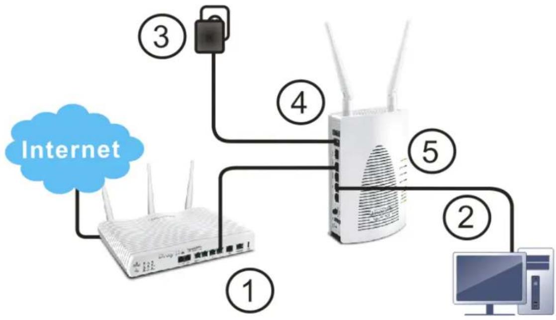
1.3.1 Wired Connection for PC in LAN
- Connect VigorAP 902 to ADSL modem, router, or switch/hub in your network through the LAN A port of the access point by Ethernet cable.
- Connect a computer to other available LAN A port. Make sure the subnet IP address of the PC is the same as VigorAP 902 management IP, e.g., 192.168.1.X.
- Connect the A/C power adapter to the wall socket, and then connect it to the PWR connector of the access point.
- Power on VigorAP 902.
- Check all LEDs on the front panel. ACT LED should blink and LAN LEDs should be on if the access point is correctly connected to the ADSL modem or router.
(For the detailed information of LED status, please refer to section 1.2.)
flowchart
graph TD
    A["Internet"] --> B["Router"]
    B --> C["Computer"]
    B --> D["Switch"]
    B --> E["Wireless Device 1"]
    B --> F["Wireless Device 2"]
    B --> G["Wireless Device 3"]
    B --> H["Wireless Device 4"]
    B --> I["Wireless Device 5"]
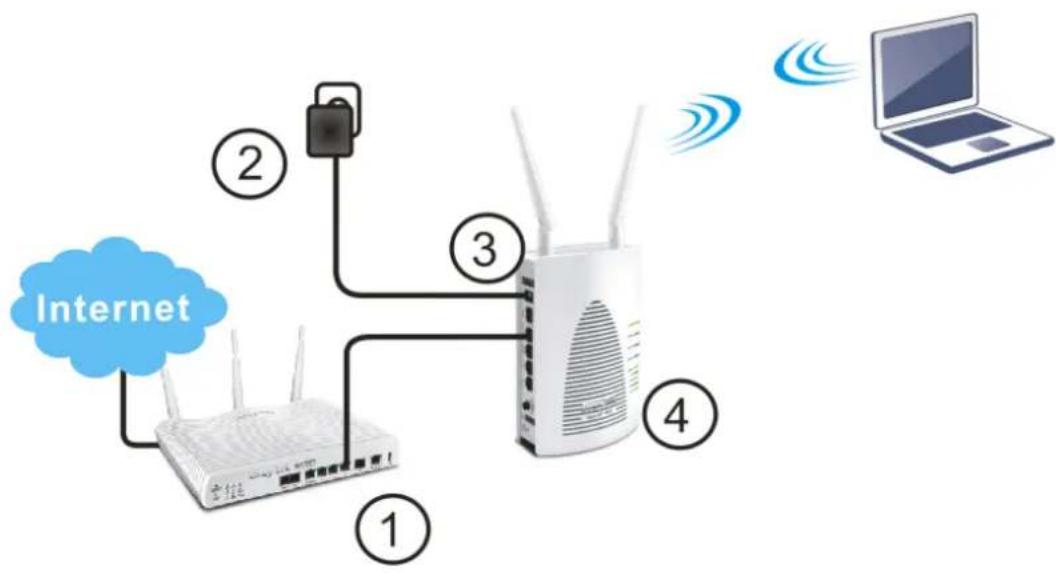
1.3.2 Wired Connection for Notebook in WLAN
- Connect VigorAP 902 to ADSL modem or router in your network through the LAN A port of the access point by Ethernet cable.
- Connect the A/C power adapter to the wall socket, and then connect it to the PWR connector of the access point.
- Power on VigorAP 902.
- Check all LEDs on the front panel. ACT LED should be steadily on, LAN LEDs should be on if the access point is correctly connected to the ADSL modem or router.
(For the detailed information of LED status, please refer to section 1.2.)
flowchart
graph TD
    A["Internet"] --> B["Rearband 1"]
    A --> C["Rearband 2"]
    A --> D["Rearband 3"]
    A --> E["Rearband 4"]
    B --> F["Wi-Fi"]
    C --> G["Wi-Fi"]
    D --> H["Wi-Fi"]
    E --> I["Wi-Fi"]
    F --> J["Laptop"]
    G --> J["Laptop"]
    H --> J["Laptop"]
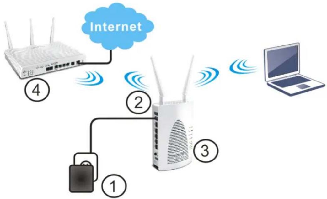
1.3.3 Wireless Connection
VigorAP 902 can access Internet via an ADSL modem, router, or switch/hub in your network through wireless connection.
- Connect the A/C power adapter to the wall socket, and then connect it to the PWR connector of the access point.
- Power on VigorAP 902.
- Check all LEDs on the front panel. ACT LED should be steadily on.
- Connect VigorAP 902 to ADSL modem or router via wireless network. (For the detailed information of LED status, please refer to section 1.2.)
flowchart
graph TD
    A["Router ④"] -->|Internet| B["Router ②"]
    B --> C["Laptop"]
    D["Switch ①"] -->|Signal| B
    E["Switch ③"] -->|Signal| B
1.3.4 PoE Connection
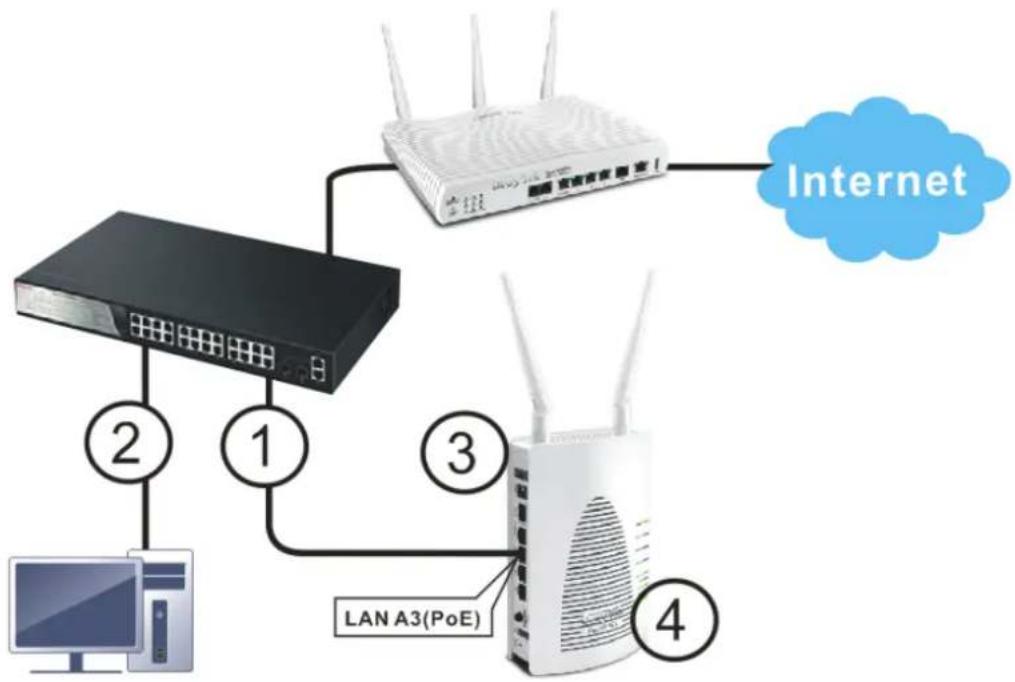
VigorAP 902 can gain the power from the connected switch, e.g., VigorSwitch P2260. PoE (Power over Ethernet) can break the install limitation caused by the fixed power supply.
-
Connect VigorAP 902 to a switch in your network through the LAN A3 (PoE) port of the access point by Ethernet cable.
-
Connect a computer to VigorSwitch P2260. Make sure the subnet IP address of the PC is the same as VigorAP 902 management IP, e.g., 192.168.1.X.
-
Power on VigorAP 902.
-
Check all LEDs on the front panel. ACT LED should be steadily on, LAN LEDs should be on if the access point is correctly connected to the ADSL modem, router or switch/hub.
After the network connection is built, the next step you should do is setup VigorAP 902 with proper network parameters, so it can work properly in your network environment.
Before you can connect to the access point and start configuration procedures, your computer must be able to get an IP address automatically (use dynamic IP address). If it's set to use static IP address, or you're unsure, please follow the following instructions to configure your computer to use dynamic IP address:
For the default IP address of this AP is set “192.168.1.2”, we recommend you to use “192.168.1.X (except 2)” in the field of IP address on this section for your computer. If the operating system of your computer is...
Windows 7 - please go to section 2.1
Windows 2000 - please go to section 2.2
Windows XP - please go to section 2.3
Windows Vista - please go to section 2.4
2.1 Windows 7 IP Address Setup
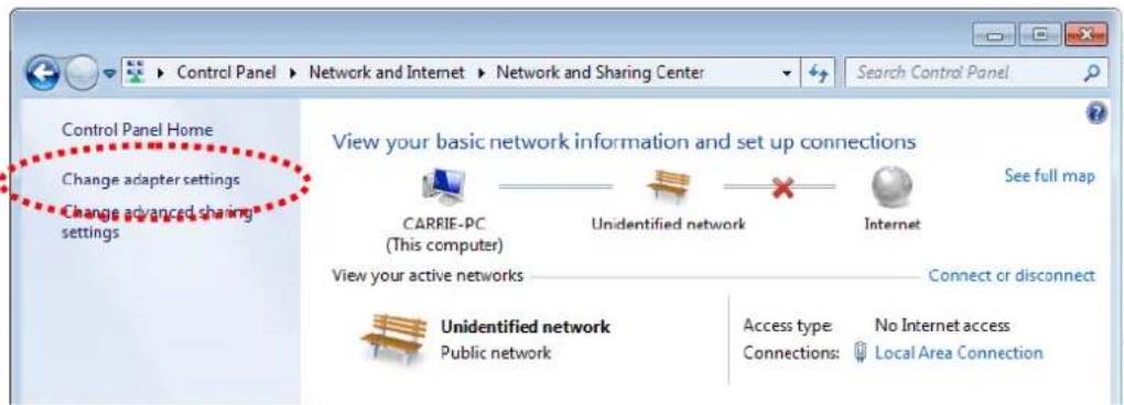
Click Start button (it should be located at lower-left corner of your computer), then click Control Panel. Double-click Network and Internet, and the following window will appear. Click Network and Sharing Center.

text_image
Control Panel Network and Internet Control Panel Home System and Security • Network and Internet Hardware and Sound Programs User Accounts and Family Safety Appearance and Personalization Clock, Language, and Region Ease of Access Network and Sharing Center View network status and tasks | Connect to a network View network computers and devices | Add a wireless device to the network HomeGroup Choose homegroup and sharing options Internet Options Change your homepage | Manage browser add-ons | Delete browsing history and cookiesNext, click Change adapter settings and click Local Area Connection.
text_image
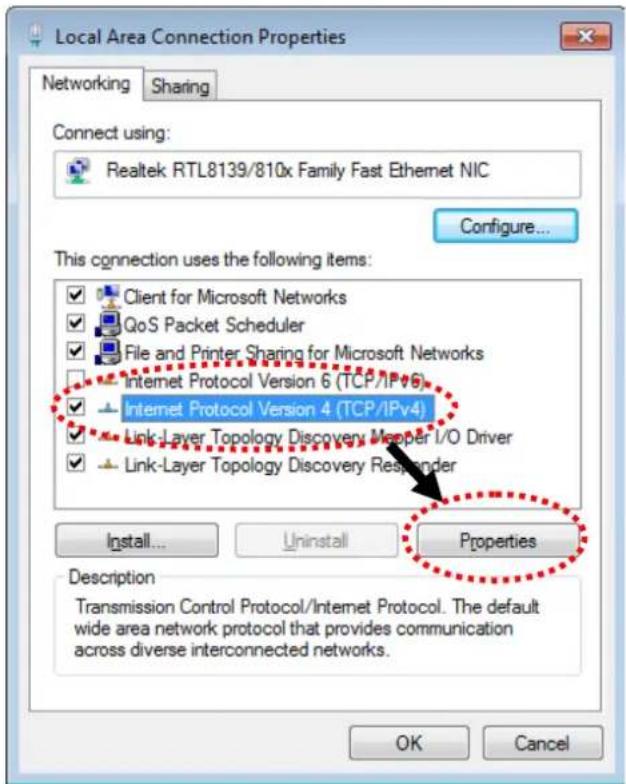
Control Panel Home Change adapter settings Change advanced sharing settings View your basic network information and set up connections CARRIE-PC (This computer) Unidentified network Internet See full map View your active networks Connect or disconnect Unidentified network Public network Access type: No Internet access Connections: Local Area ConnectionThen, select Internet Protocol Version 4 (TCP/IPv4) and click Properties.
text_image
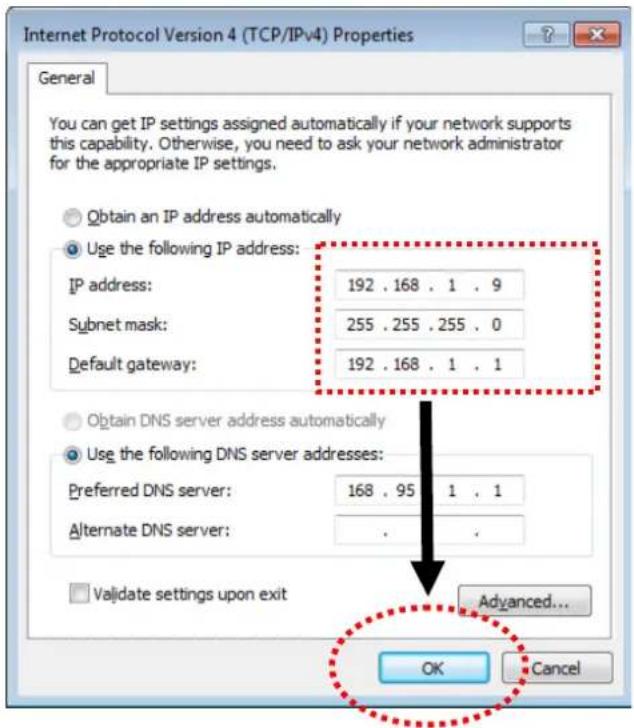
Local Area Connection Properties Networking Sharing Connect using: Realtek RTL8139/810x Family Fast Ethernet NIC Configure... This connection uses the following items: ✓ Client for Microsoft Networks ✓ QoS Packet Scheduler ✓ File and Printer Sharing for Microsoft Networks ■ Internet Protocol Version 6 (TCP/IPv6) ✓ Internet Protocol Version 4 (TCP/IPv4) ✓ Link-Layer Topology Discovery Meaper I/O Driver ✓ Link-Layer Topology Discovery Responder Install... Uninstall Properties Description Transmission Control Protocol/Internet Protocol. The default wide area network protocol that provides communication across diverse interconnected networks. OK CancelUnder the General tab, click Use the following IP address. Then input the following settings in respective field and click OK when finish.
IP address: 192.168.1.9
Subnet Mask: 255.255.255.0
text_image
Internet Protocol Version 4 (TCP/IPv4) Properties General You can get IP settings assigned automatically if your network supports this capability. Otherwise, you need to ask your network administrator for the appropriate IP settings. Obtain an IP address automatically Use the following IP address: IP address: 192 . 168 . 1 . 9 Subnet mask: 255 . 255 . 255 . 0 Default gateway: 192 . 168 . 1 . 1 Obtain DNS server address automatically Use the following DNS server addresses: Preferred DNS server: 168 . 95 . 1 . 1 Alternate DNS server: . Validate settings upon exit Advanced... OK Cancel2.2 Windows 2000 IP Address Setup
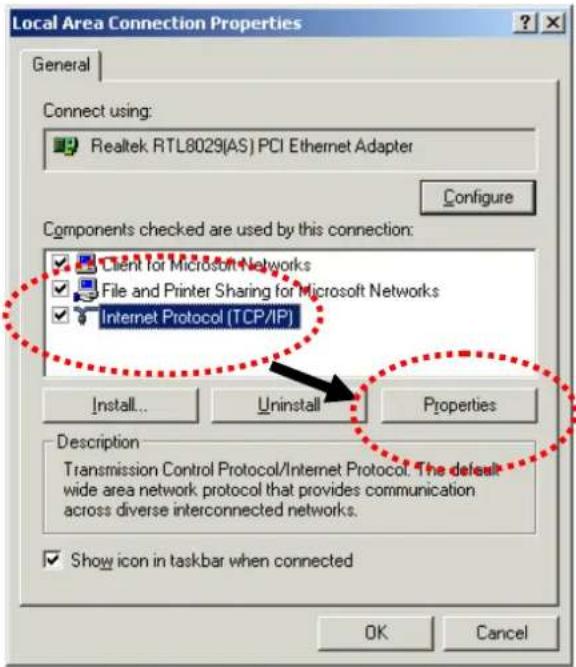
Click Start button (it should be located at lower-left corner of your computer), then click control panel. Double-click Network and Dial-up Connections icon, double click Local Area Connection, and Local Area Connection Properties window will appear. Select Internet Protocol (TCP/IP), then click Properties.
text_image
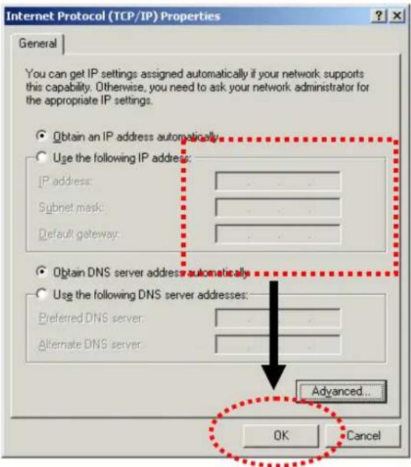
Local Area Connection Properties General Connect using: Realtek RTL8029(AS) PCI Ethernet Adapter Configure Components checked are used by this connection: Client for Microsoft Networks File and Printer Sharing for Microsoft Networks Internet Protocol [TCP/IP] Install... Uninstall Properties Description Transmission Control Protocol/Internet Protocol. The default wide area network protocol that provides communication across diverse interconnected networks. Show icon in taskbar when connected OK CancelSelect Use the following IP address, then input the following settings in respective field and click OK when finish.
IP address: 192.168.1.9
Subnet Mask: 255.255.255.0
text_image
Internet Protocol (TCP/IP) Properties General You can get IP settings assigned automatically if your network supports this capability. Otherwise, you need to ask your network administrator for the appropriate IP settings. Obtain an IP address automatically Use the following IP address: IP address: Subnet mask: Default gateway: Obtain DNS server address automatically Use the following DNS server addresses: Preferred DNS server: Alternate DNS server: Advanced... OK Cancel2.3 Windows XP IP Address Setup
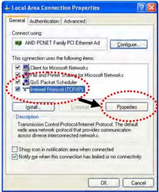
Click Start button (it should be located at lower-left corner of your computer), then click control panel. Double-click Network and Internet Connections icon, click Network Connections, and then double-click Local Area Connection, Local Area Connection Status window will appear, and then click Properties.
text_image
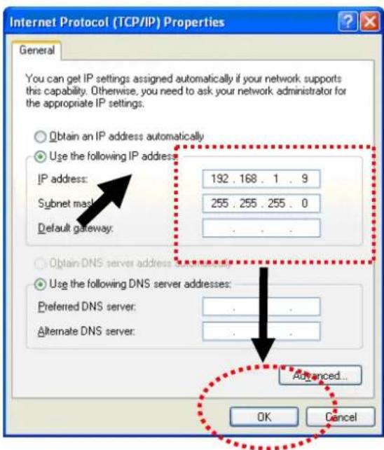
Local Area Connection Properties General Authentication Advanced Connect using: AMD PCNET Family PCI Ethernet Ad Configure... This connection uses the following items: ✓ Client for Microsoft Networks ✓ File and Printer Sharing for Microsoft Networks ✓ QoS Packet Scheduler ✓ Internet Protocol [TCP/IP] Install... Unwired Properties Description Transmission Control Protocol/Internet Protocol. The default wide area network protocol that provides communication across diverse interconnected networks. Show icon in notification area when connected Notify me when this connection has limited or no connectivity OK CancelSelect Use the following IP address, then input the following settings in respective field and click OK when finish:
IP address: 192.168.1.9
Subnet Mask: 255.255.255.0.
text_image
Internet Protocol (TCP/IP) Properties General You can get IP settings assigned automatically if your network supports this capability. Otherwise, you need to ask your network administrator for the appropriate IP settings. Obtain an IP address automatically Use the following IP address: IP address: 192 . 168 . 1 . 9 Subnet mask: 255 . 255 . 255 . 0 Default gateway: . Obtain DNS server address automatically Use the following DNS server addresses: Preferred DNS server: . Alternate DNS server: . Advanced... OK Cancel2.4 Windows Vista IP Address Setup
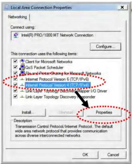
Click Start button (it should be located at lower-left corner of your computer), then click control panel. Click View Network Status and Tasks, then click Manage Network Connections. Right-click Local Area Netwrok, then select 'Properties'. Local Area Connection Properties window will appear, select Internet Protocol Version 4 (TCP / IPv4), and then click Properties.
text_image
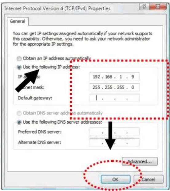
Local Area Connection Properties Networking | Connect using: Intel(R) PRO/1000 MT Network Connection Configure... This connection uses the following items: Client for Microsoft Networks QoS Packet Scheduler File and Printer Sharing for Microsoft Networks Internet Protocol Version 6 (TCP/IPv6) Internet Protocol Version 4 (TCP/IPv4) Link-Layer Topology Discovery Mapper I/O Driver Link-Layer Topology Discovery Responder Install... Uninstall Properties Description Transmission Control Protocol/Internet Protocol. The default wide area network protocol that provides communication across diverse interconnected networks. OK CancelSelect Use the following IP address, then input the following settings in respective field and click OK when finish:
IP address: 192.168.1.9
Subnet Mask: 255.255.255.0.
text_image
Internet Protocol Version 4 (TCP/IPv4) Properties General You can get IP settings assigned automatically if your network supports this capability. Otherwise, you need to ask your network administrator for the appropriate IP settings. Obtain an IP address automatically Use the following IP address: IP address: 192 . 168 . 1 . 9 Internet mask: 255 . 255 . 255 . 0 Default gateway: | Obtain DNS server address automatically Use the following DNS server addresses: Preferred DNS server: . Alternate DNS server: . Advanced... OK Cancel2.5 Accessing to Web User Interface
All functions and settings of this access point must be configured via web user interface. Please start your web browser (e.g., Firefox).
-
Make sure your PC connects to the VigorAP 902 correctly.
-
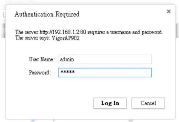
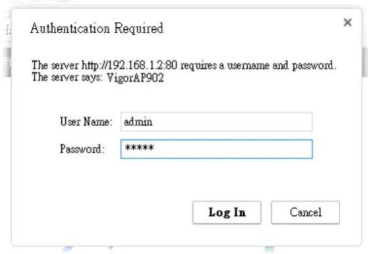
Open a web browser on your PC and type http://192.168.1.2. A pop-up window will open to ask for username and password. Pease type "admin/admin" on Username/Password and click OK.
text_image
Authentication Required The server http://192.168.1.2:80 requires a username and password. The server says: VigorAP902 User Name: admin Password: ***** Log In CancelNote 1: You may either simply set up your computer to get IP dynamically from the router or set up the IP address of the computer to be in the same subnet as the IP address of VigorAP 902.
- If there is no DHCP server on the network, then VigorAP 902 will have an IP address of 192.168.1.2.
-
If there is DHCP available on the network, then VigorAP 902 will receive it's IP address via the DHCP server.
-
The Main Screen will pop up.
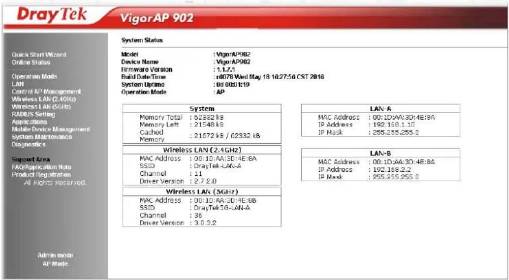
text_image
DrayTek VigorAP 902 System Status Model : VigorAP902 Device Name : VigorAP902 Firmware Version : 1.1.7.1 Build Date/Time : r6078 Wed May 18 16:27:56 CST 2016 System Uptime : 0d 00:01:19 Operation Mode : AP System Memory Total : 62332 kB Memory Left : 21548 kB Cached : 21672 kB / 62332 kB Memory LAN-A MAC Address : 00:1D:AA:3D:4E:8A IP Address : 192.168.1.10 IP Mask : 255.255.255.0 Wireless LAN (2.4GHz) MAC Address : 00:1D:AA:3D:4E:8A SSID : DrayTek-LAN-A Channel : 11 Driver Version : 2.7.2.0 LAN-B MAC Address : 00:1D:AA:3D:4E:8A IP Address : 192.168.2.2 IP Mask : 255.255.255.0 Wireless LAN (5GHz) MAC Address : 00:1D:AA:3D:4E:8B SSID : DrayTek5G-LAN-A Channel : 36 Driver Version : 3.0.3.2 Admin mode AP ModeNote: If you fail to access to the web configuration, please go to "Trouble Shooting" for detecting and solving your problem. For using the device properly, it is necessary for you to change the password of web configuration for security and adjust primary basic settings.
2.6 Changing Password
- Please change the password for the original security of the modem.
- Go to System Maintenance page and choose Administration Password.
System Maintenance >> Administration Password
Administrator Settings

text_image
Account admin Password •••••• Confirm PasswordNote: Authorization can contain only a-z A-Z 0-9, \~ ' ! @ # \$ % ^ & * () _ + = {} [] | \ ; '< > . ? /
OK Cancel
- Enter the new login password on the field of Password. Then click OK to continue.
- Now, the password has been changed. Next time, use the new password to access the Web User Interface for this modem.
text_image
Authentication Required The server http://192.168.1.2:80 requires a username and password. The server says: VigorAP902 User Name: admin Password: ***** Log In Cancel2.7 Quick Start Wizard
Quick Start Wizard will guide you to configure 2.4G wireless setting, 5G wireless setting and other corresponding settings for Vigor Access Point step by step.
2.7.1 Configuring 2.4GHz Wireless Settings – General
This page displays general settings for the operation mode selected.
Quick Start Wizard >> Wireless LAN (2.4GHz)
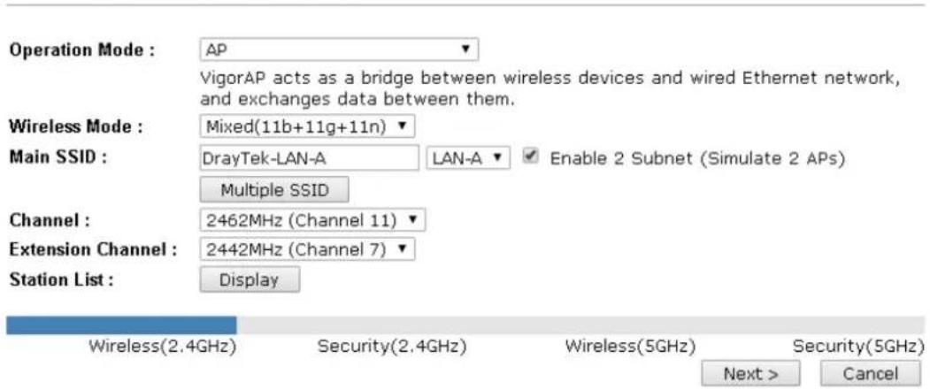
text_image
Operation Mode : VigorAP acts as a bridge between wireless devices and wired Ethernet network, and exchanges data between them. Wireless Mode : Mixed(11b+11g+11n) Main SSID : DrayTek-LAN-A LAN-A Enable 2 Subnet (Simulate 2 APs) Multiple SSID Channel : 2462MHz (Channel 11) Extension Channel : 2442MHz (Channel 7) Station List : Display Wireless(2.4GHz) Security(2.4GHz) Wireless(5GHz) Security(5GHz) Next > CancelAvailable settings are explained as follows:
| Item | Description |
| Operation Mode | There are five operation modes for wireless connection. Settings for each mode are different.AP ▼APStation-InfrastructureAP Bridge-Point to PointAP Bridge-Point to Multi-PointAP Bridge-WDSUniversal Repeater |
| Wireless Mode | At present, VigorAP 902 can connect to 11b only, 11g only, 11n only, Mixed (11b+11g), Mixed (11g+11n) and Mixed (11b+11g+11n) stations simultaneously. Simply choose Mixed (11b+11g+11n) mode.Mixed(11b+11g+11n) ▼11b Only11g Only11n OnlyMixed(11b+11g)Mixed(11g+11n)Mixed(11b+11g+11n) |
| Main SSID | Set a name for VigorAP 902 to be identified.Enable 2 Subnet (Simulate 2 APs) - Check the box to enable the function for two independent subnets. Once you enable this function, LAN-A and LAN-B would be independent. Next, you can connect one router in LAN-A, and another router in LAN-B. Such mechanism can make you feeling that you have twoindependent AP/subnet functions in one VigorAP 902.If you disable this function, LAN-A and LAN-B ports are in the same domain. You could only connect one router (no matter connecting to LAN-A or LAN-B) in this environment.Multiple SSID - When Enable 2 Subnet is enabled, you can specify subnet interface (LAN-A or LAN-B) for each SSID by using the drop down menu. |
| Channel | Means the channel frequency of the wireless LAN. The default channel is 6. You may switch channel if the selected channel is under serious interference. If you have no idea of choosing the frequency, please selectAutoSelectto let system determine for you.[IMAGE] |
| Extension Channel | With 802.11n, there is one option to double the bandwidth per channel. The available extension channel options will be varied according to theChannelselected above. |
| Station List | Click theDisplaybutton to open the Station List dialog. It provides the knowledge of connecting wireless clients now along with its status code. |
| AP Discovery | Click this button to open the AP Discovery dialog. VigorAP 902 can scan all regulatory channels and find working APs in the neighborhood.This option is not available whenAPis selected as theOperation Mode. |
After finishing this web page configuration, please click Next to continue.
2.7.2 Configuring 2.4GHz Wireless Settings based on the Operation Mode
In this page, the advanced settings will vary according to the operation mode chosen on 2.7.1.
Advanced Settings for Station-Infrastructure
When you choose Station-Infrastructure and click Next, you will need to configure the following page to connect to one AP.
Quick Start Wizard >> Wireless LAN (2.4GHz)
Setup Profile to connect to AP :
| System Configuration | |
| Profile Name | PROF001 |
| SSID | |
| Network Type | Infrastructure |
| Power Saving Mode | CAM (Constantly Awake Mode)Power Saving Mode |
| RTS Threshold | Used 2347 |
| Fragment Threshold | Used 2346 |
| Security Policy | |
| Security Mode | OPEN |
| WEP | ||
| WEP Key Length | 64 bit (10 hex digits / 5 ascii keys) | |
| WEP Key Entry Method | Hexadecimal | |
| WEP Keys | WEP Key 1 : | |
| WEP Key 2 : | ||
| WEP Key 3 : | ||
| WEP Key 4 : | ||
| Default Key | Key 1 | |

Available settings are explained as follows:
| Item | Description |
| SystemConfiguration | Profile Name -Type a name for the new profile.SSID - Type the name for such access point that can be used for connection by the stations.Network TypeInfrastructure802.11 Ad HocInfrastructureInfrastructureInfrastructure- In this mode, you can connect the access point to Ethernet device such as TV and Game player to enable the Ethernet device as a wireless station and join to a wireless network through an access point or AP router.802.11 Ad Hoc – An ad-hoc network is a network where wireless stations can communicate with peer to peer (P2P).Power Saving Mode - Choose the power saving mode for suchdevice.CAM – Choose this item if it is not necessary to perform power saving job.Power Saving Mode – Choose this item to get into the power saving status when there is no data passing through the access point.RTS Threshold- Set the RTS threshold of wireless radio. Do not modify default value if you don’t know what it is, default value is 2347 Fragment Threshold - Set the Fragment threshold of wireless radio. Do not modify default value if you don’t know what it is, default value is 2346. |
| Security Mode | 802.11 standard defines two mechanisms for authentication of wireless LAN clients: Open Authentication and Shared Key Authentication.Choose one of the security modes from the drop down list. If you choose OPEN or SHARED, you have to type WEP information.OPEN – Open authentication is basically null authentication algorithm, which means that there is no verification of the user.SHARED – It works similar to Open authentication with only one major difference. If you choose OPEN with WEP encryption key, the WEP keys is used to encrypt and decrypt the data but not for authentication. In Shared key authentication, WEP encryption will be used for authentication.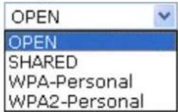 If you choose WPA-Personal or WPA2-Personal, the corresponding WPA settings will be listed as follows. You have to choose the WPA algorithms and type the pass phrase for such security mode. If you choose WPA-Personal or WPA2-Personal, the corresponding WPA settings will be listed as follows. You have to choose the WPA algorithms and type the pass phrase for such security mode.  WPA Algorithms – Choose Temporal Key Integrity Protocol (TKIP) or AES for data encryption.Pass Phrase – Please type 8 to 63 alphanumerical characters here. WPA Algorithms – Choose Temporal Key Integrity Protocol (TKIP) or AES for data encryption.Pass Phrase – Please type 8 to 63 alphanumerical characters here. |
| WEP | WEP Key Length - WEP (Wired Equivalent Privacy) is a common encryption mode. It is safe enough for home and personal use. However, if you need higher level of security, please consider using WPA encryption (see next section). |
Some wireless clients do not support WPA, but support WEP. Therefore WEP is still a good choice for you if you have such kind of client in your network environment.

text_image
64 bit (10 hex digits / 5 ascii keys) 64 bit (10 hex digits / 5 ascii keys) 128 bit (26 hex digits / 13 ascii keys)WEP Key Entry Method - There are two types of WEP key length: 64-bit and 128-bit. Using 128-bit is safer than 64-bit, but it will reduce some data transfer performance.
There are two types of key method: ASCII and Hex. When you select a key format, the number of characters of key will be displayed. For example, if you select 64-bit as key length, and Hex as key format, you'll see the message at the right of Key Format is 'Hex (10 characters) which means the length of WEP key is 10 characters.
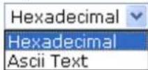
WEP Keys (Key 1 – Key 4) - Four keys can be entered here, but only one key can be selected at a time. The format of WEP Key is restricted to 5 ASCII characters or 10 hexadecimal values in 64-bit encryption level, or restricted to 13 ASCII characters or 26 hexadecimal values in 128-bit encryption level. The allowed content is the ASCII characters from 33(!) to 126(\~) except '#' and Documentary'. Such feature is available for WEP mode.
Default Key – Choose one of the key settings.
Advanced Settings for AP Bridge-Point to Point
When you choose AP Bridge-Point to Point, you will need to configure the following page.
Quick Start Wizard >> Wireless LAN (2.4GHz)
Note: Enter the configuration of APs which AP 900 want to connect.
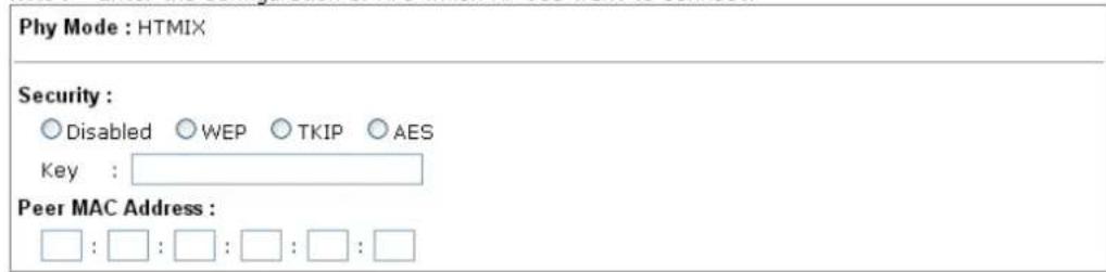
text_image
Phy Mode : HTMIX Security : ○ Disabled ○ WEP ○ TKIP ○ AES Key : Peer MAC Address : □ : □ : □ : □ : □ : □
Available settings are explained as follows:
| Item | Description |
| PHY Mode | Data will be transmitted via HTMIX mode.Each access point should be setup to the same PHY Mode for connecting with each other. |
| Security | Select WEP, TKIP or AES as the encryption algorithm. Type the key number if required. |
| Peer MAC Address | Type the peer MAC address for the access point that VigorAP 902 connects to. |
Advanced Settings for AP Bridge-Point to Multi-Point
When you choose AP Bridge-Point to Multi-Point, you will need to configure the following page.
Quick Start Wizard >> Wireless LAN (2.4GHz)
Note : Enter the configuration of APs which AP 900 want to connect.
Phy Mode : HTMIX
- Security :
< Back Next > Cancel
Available settings are explained as follows:
| Item | Description |
| PHY Mode | Data will be transmitted via HTMIX mode.Each access point should be setup to the same PHY Mode for connecting with each other. |
| Security | Select WEP, TKIP or AES as the encryption algorithm. Type the key number if required. |
| Peer MAC Address | Type the peer MAC address for the access point that VigorAP 902 connects to. |
Advanced Settings for AP Bridge-WDS
When you choose AP Bridge-WDS, you will need to configure the following page.
Quick Start Wizard >> Wireless LAN (2.4GHz)
Note: Enter the configuration of APs which AP 900 want to connect. Remote AP should always set LAN-A MAC address to connect AP900 WDS.
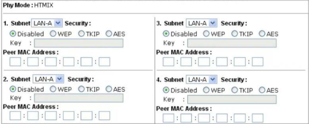
text_image
Phy Mode : HTMIX 1. Subnet LAN-A Security: ● Disabled ○ WEP ○ TKIP ○ AES Key : Peer MAC Address : □ : □ : □ : □ : □ : □ 2. Subnet LAN-A Security: ● Disabled ○ WEP ○ TKIP ○ AES Key : Peer MAC Address : □ : □ : □ : □ : □ : □ 3. Subnet LAN-A Security: ● Disabled ○ WEP ○ TKIP ○ AES Key : Peer MAC Address : □ : □ : □ : □ : □ : □ 4. Subnet LAN-A Security: ● Disabled ○ WEP ○ TKIP ○ AES Key : Peer MAC Address : □ : □ : □ : □ : □ : □
Available settings are explained as follows:
| Item | Description |
| PHY Mode | Data will be transmitted via HTMIX mode.Each access point should be setup to the same PHY Mode for connecting with each other. |
| Subnet | Choose LAN-A or LAN-B for each SSID. |
| Security | Select WEP, TKIP or AES as the encryption algorithm. Type the key number if required. |
| Peer MAC Address | Type the peer MAC address for the access point that VigorAP 902 connects to. |
Advanced Settings for AP Bridge-Universal Repeater
When you choose AP Bridge-Universal Repeater you will need to configure the following page.
Quick Start Wizard >> Wireless LAN (2.4GHz)
Please input the SSID you want to connect to : Universal Repeater Parameters
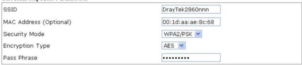
text_image
SSID DrayTek2860nnn MAC Address (Optional) 00:1d:aa:ae:8c:68 Security Mode WPA2/PSK Encryption Type AES Pass Phrase ••••••••••••
Available settings are explained as follows:
| Item | Description |
| SSID | Means the identification of the wireless LAN. SSID can be any text numbers or various special characters. |
| MAC Address (Optional) | Type the MAC address for the access point. |
| Security Mode | There are several modes provided for you to choose. Each mode will bring up different parameters (e.g., WEP keys, Pass Phrase) for you to configure.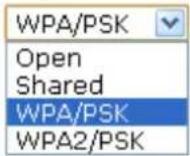 |
| Encryption Type for Open/Shared | This option is available when Open/Shared is selected as Security Mode.Choose None to disable the WEP Encryption. Data sent to the AP will not be encrypted. To enable WEP encryption for data transmission, please choose WEP.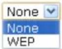 WEP Keys - Four keys can be entered here, but only one key can be selected at a time. The format of WEP Key is restricted to 5 ASCII characters or 10 hexadecimal values in 64-bit encryption level, or restricted to 13 ASCII characters or 26 hexadecimal values in 128-bit encryption level. The allowed content is the ASCII characters from 33(!) to 126(~) except '#' and ','. WEP Keys - Four keys can be entered here, but only one key can be selected at a time. The format of WEP Key is restricted to 5 ASCII characters or 10 hexadecimal values in 64-bit encryption level, or restricted to 13 ASCII characters or 26 hexadecimal values in 128-bit encryption level. The allowed content is the ASCII characters from 33(!) to 126(~) except '#' and ','.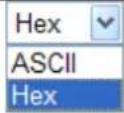 |
| Encryption Type for WPA/PSK and WPA2/PSK | This option is available when WPA/PSK or WPA2/PSK is selected as Security Mode.Select TKIP or AES as the algorithm for WPA.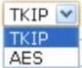 |
| Pass Phrase | It is available when WPA/PSK or WPA2/PSK is selected. |
After finishing this web page configuration, please click Next to continue.
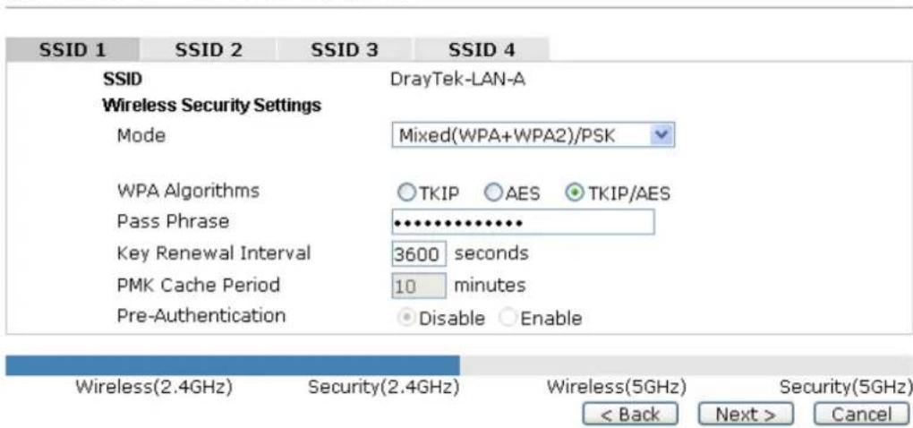
2.7.3 Configuring 2.4GHz Security Settings
VigorAP 902 offers 2.4GHz wireless connection capability. You can setup 2.4GHz features in Quick Start Wizard first. Once the USB 2.4GHz wireless dongle connects to VigorAP 902, it can work immediately.
Quick Start Wizard >> Wireless Security (2.4GHz)
text_image
SSID 1 SSID 2 SSID 3 SSID 4 SSID DrayTek-LAN-A Wireless Security Settings Mode Mixed(WPA+WPA2)/PSK WPA Algorithms ○ TKIP ○ AES ● TKIP/AES Pass Phrase •••••••••••••• Key Renewal Interval 3600 seconds PMK Cache Period 10 minutes Pre-Authentication ● Disable ○ Enable Wireless(2.4GHz) Security(2.4GHz) Wireless(5GHz) Security(5GHz) < Back Next > CancelAvailable settings are explained as follows:
| Item | Description |
| Mode | There are several modes provided for you to choose. |
| DisableDisableWEPWPA/PSKWPA2/PSKMixed(WPA+WPA2)/PSKWEP/802.1xWPA/802.1xWPA2/802.1xMixed(WPA+WPA2)/802.1xDisable - The encryption mechanism is turned off.WEP - Accepts only WEP clients and the encryption key should be entered in WEP Key.WPA/PSK or WPA2/PSK or Mixed (WPA+WPA2)/PSK -Accepts only WPA clients and the encryption key should be entered in PSK. The WPA encrypts each frame transmitted from the radio using the key, which either PSK (Pre-Shared Key) entered manually in this field below or automatically negotiated via 802.1x authentication.WEP/802.1x - The built-in RADIUS client feature enables VigorAP 902 to assist the remote dial-in user or a wireless station and the RADIUS server in performing mutual authentication. It enables centralized remote access authentication for network management.WPA/802.1x - The WPA encrypts each frame transmitted from the radio using the key, which either PSK (Pre-Shared Key) entered manually in this field below or automatically negotiated via 802.1x authentication.WPA2/802.1x - The WPA encrypts each frame transmitted from the radio using the key, which either PSK (Pre-Shared Key) entered manually in this field below or automatically negotiated via 802.1x authentication. | |
| WPA Algorithm | Select TKIP, AES or TKIP/AES as the algorithm for WPA. Such feature is available for WPA2/802.1x, WPA/802.1x, WPA/PSK or WPA2/PSK or Mixed (WPA+WPA2)/PSK mode. |
| Pass Phrase | Either 8~63 ASCII characters, such as 012345678..(or 64 Hexadecimal digits leading by 0x, such as "0x321253abcde..."). Such feature is available for WPA/PSK or WPA2/PSK or Mixed (WPA+WPA2)/PSK mode. |
| Key Renewal Internal | WPA uses shared key for authentication to the network. However, normal network operations use a different encryption key that is randomly generated. This randomly generated key that is periodically replaced. Enter the renewal security time (seconds) in the column. Smaller interval leads to greater security but lower performance. Default is 3600 seconds. Set 0 to disable re-key. Such feature is available for WPA2/802.1,WPA/802.1x, WPA/PSK or WPA2/PSK or Mixed (WPA+WPA2)/PSK mode. |
| PMK Cache Period | Set the expire time of WPA2 PMK (Pairwise master key) cache. PMK Cache manages the list from the BSSIDs in the associated SSID with which it has pre-authenticated. Such feature is available for WPA2/802.1 mode. |
| Pre-Authentication | Enables a station to authenticate to multiple APs for roaming securer and faster. With the pre-authentication procedure defined in IEEE 802.11i specification, the pre-four-way-handshake can reduce handoff delay perceivable by a mobile node. It makes roaming faster and more secure. (Only valid in WPA2) Enable - Enable IEEE 802.1X Pre-Authentication. Disable - Disable IEEE 802.1X Pre-Authentication. |
| Key 1 - Key 4 | Four keys can be entered here, but only one key can be selected at a time. The format of WEP Key is restricted to 5 ASCII characters or 10 hexadecimal values in 64-bit encryption level, or restricted to 13 ASCII characters or 26 hexadecimal values in 128-bit encryption level. The allowed content is the ASCII characters from 33(!) to 126(~) except '#' and ''. |
| 802.1x WEP | Disable - Disable the WEP Encryption. Data sent to the AP will not be encrypted. Enable - Enable the WEP Encryption. Such feature is available for WEP/802.1x mode. |
After finishing this web page configuration, please click Next to continue.
2.7.4 Configuring 5GHz Wireless Settings
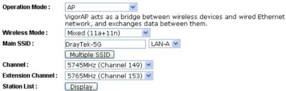
VigorAP 902 offers 5GHz wireless connection capability. You can setup 5GHz features in Quick Start Wizard first. Once the USB 5GHz wireless dongle connects to VigorAP 902, it can work immediately.
Quick Start Wizard >> Wireless LAN (5GHz)
text_image
Operation Mode : AP VigorAP acts as a bridge between wireless devices and wired Ethernet network, and exchanges data between them. Wireless Mode : Mixed (11a+11n) Main SSID : DrayTek-5G LAN-A Multiple SSID Channel : 5745MHz (Channel 149) Extension Channel : 5765MHz (Channel 153) Station List : Display
text_image
Wireless(2.4GHz) Security(2.4GHz) Wireless(5GHz) Security(5GHz) < Back Next > CancelAvailable settings are explained as follows:
| Item | Description |
| Operation Mode | There are two operation modes for wireless connection. Settings for each mode are different.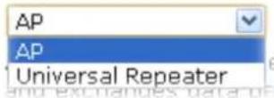 |
| Wireless Mode | At present, VigorAP 902 can connect to 11a only, 11n only (5G), Mixed (11a+11n) and Mixed (11a+11n+11ac) stations simultaneously. Simply choose Mixed (11a+11n+11ac) mode.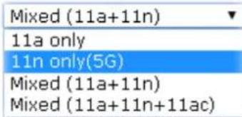 |
| Main SSID | Set a name for VigorAP 902 to be identified.Multiple SSID – Set the SSIDs and specify subnet interface (LAN-A or LAN-B) for each SSID by click Multiple SSID. |
| Channel | Means the channel of frequency of the wireless LAN. The default channel is 36. You may switch channel if the selected channel is under serious interference. |
| Extension Channel | With 802.11n, there is one option to double the bandwidth per channel. The available extension channel options will be varied according to the Channel selected above. |
| Station List | Click the Display button to open the Station List dialog. Itprovides the knowledge of connecting wireless clients now along with its status code. |
| AP Discovery | Click this button to open the AP Discovery dialog. VigorAP 902 can scan all regulatory channels and find working APs in the neighborhood.This option is not available when AP is selected as the Operation Mode. |
After finishing this web page configuration, please click Next to continue.
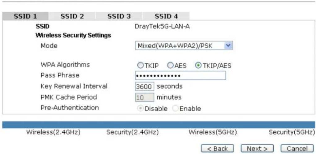
2.7.5 Configuring 5GHz Security Settings
VigorAP 902 offers 5GHz wireless connection capability. You can setup 5G features in Quick Start Wizard first. Once the USB 5GHz wireless dongle connects to VigorAP 902, it can work immediately.
Quick Start Wizard >> Wireless Security (5GHz)
text_image
SSID 1 SSID 2 SSID 3 SSID 4 SSID DrayTek5G-LAN-A Wireless Security Settings Mode Mixed(WPA+WPA2)/PSK WPA Algorithms ○TKIP ○AES ●TKIP/AES Pass Phrase •••••••••••••• Key Renewal Interval 3600 seconds PMK Cache Period 10 minutes Pre-Authentication ●Disable ○Enable Wireless(2.4GHz) Security(2.4GHz) Wireless(5GHz) Security(5GHz) < Back Next > CancelAvailable settings are explained as follows:
| Item | Description |
| Mode | There are several modes provided for you to choose. |
| DisableDisableWEPWPA/PSKWPA2/PSKMixed(WPA+WPA2)/PSKWEP/802.1xWPA/802.1xWPA2/802.1xMixed(WPA+WPA2)/802.1x | |
| Disable - The encryption mechanism is turned off.WEP - Accepts only WEP clients and the encryption key should be entered in WEP Key.WPA/PSK or WPA2/PSK or Mixed (WPA+WPA2)/PSK -Accepts only WPA clients and the encryption key should be entered in PSK. The WPA encrypts each frame transmitted from the radio using the key, which either PSK (Pre-Shared Key) entered manually in this field below or automatically negotiatedvia 802.1x authentication.WEP/802.1x - The built-in RADIUS client feature enables VigorAP 902 to assist the remote dial-in user or a wireless station and the RADIUS server in performing mutual authentication. It enables centralized remote access authentication for network management.The WPA encrypts each frame transmitted from the radio using the key, which either PSK (Pre-Shared Key) entered manually in this field below or automatically negotiated via 802.1x authentication. Select WPA, WPA2 or Auto as WPA mode.WPA/802.1x - The WPA encrypts each frame transmitted from the radio using the key, which either PSK (Pre-Shared Key) entered manually in this field below or automatically negotiated via 802.1x authentication.WPA2/802.1x - The WPA encrypts each frame transmitted from the radio using the key, which either PSK (Pre-Shared Key) entered manually in this field below or automatically negotiated via 802.1x authentication. | |
| WPA Algorithm | Select TKIP, AES or TKIP/AES as the algorithm for WPA. Such feature is available for WPA2/802.1x, WPA/802.1x, WPA/PSK or WPA2/PSK or Mixed (WPA+WPA2)/PSK mode. |
| Pass Phrase | Either 8~63 ASCII characters, such as 012345678..(or 64 Hexadecimal digits leading by 0x, such as "0x321253abcde..."). Such feature is available for WPA/PSK or WPA2/PSK or Mixed (WPA+WPA2)/PSK mode. |
| Key Renewal Internal | WPA uses shared key for authentication to the network. However, normal network operations use a different encryption key that is randomly generated. This randomly generated key that is periodically replaced. Enter the renewal security time (seconds) in the column. Smaller interval leads to greater security but lower performance. Default is 3600 seconds. Set 0 to disable re-key. Such feature is available for WPA2/802.1,WPA/802.1x, WPA/PSK or WPA2/PSK or Mixed (WPA+WPA2)/PSK mode. |
| PMK Cache Period | Set the expire time of WPA2 PMK (Pairwise master key) cache. PMK Cache manages the list from the BSSIDs in the associated SSID with which it has pre-authenticated. Such feature is available for WPA2/802.1 mode. |
| Pre-Authentication | Enables a station to authenticate to multiple APs for roaming securer and faster. With the pre-authentication procedure defined in IEEE 802.11i specification, the pre-four-way-handshake can reduce handoff delay perceivable by a mobile node. It makes roaming faster and more secure. (Only valid in WPA2)Enable - Enable IEEE 802.1X Pre-Authentication.Disable - Disable IEEE 802.1X Pre-Authentication. |
| Key 1 - Key 4 | Four keys can be entered here, but only one key can be selected at a time. The format of WEP Key is restricted to 5 ASCII characters or 10 hexadecimal values in 64-bit encryption level, or restricted to 13 ASCII characters or 26 hexadecimal values in128-bit encryption level. The allowed content is the ASCII characters from 33(!) to 126(~) except '#' and ','. |
| 802.1x WEP | Disable - Disable the WEP Encryption. Data sent to the AP will not be encrypted.Enable - Enable the WEP Encryption.Such feature is available for WEP/802.1x mode. |
After finishing this web page configuration, please click Next to continue.
2.7.6 Finishing the Wireless Settings Wizard
When you see this page, it means the wireless setting wizard is almost finished. Just click Finish to save the settings and complete the setting procedure.
Quick Start Wizard
Vigor Wizard Setup is now finished!
Basic Settings for VigorAP is completed.
Press Finish button to save and finish the wizard setup.
Note that the configuration process takes a few seconds to complete.
< Back Finish Cancel
2.8 Online Status
The online status shows the LAN status, Station Link Status for such device.
Online Status
| System Status | System Uptime: 0d 00:11:40 | |||
| LAN-A Status | ||||
| IP Address | TX Packets | RX Packets | TX Bytes | RX Bytes |
| 192.168.1.2 | 3982 | 2457 | 4278077 | 218353 |
| LAN-B Status | ||||
| IP Address | TX Packets | RX Packets | TX Bytes | RX Bytes |
| 192.168.2.2 | 0 | 0 | 0 | 0 |
| Universal Repeater 5GHz Status | ||||
| IP | Gateway | SSID | Channel | |
| 149 | ||||
| Remote Mac | Security Mode | TX Packets | RX Packets | |
| 3 | 551 | |||
Detailed explanation is shown below:
| Item | Description |
| IP Address | Displays the IP address of the LAN interface. |
| TX Packets | Displays the total transmitted packets at the LAN interface. |
| RX Packets | Displays the total number of received packets at the LAN interface. |
| TX Bytes | Displays the total transmitted size at the LAN interface. |
| RX Bytes | Displays the total number of received size at the LAN interface. |
This page is left blank.
3
Advanced Configuration
This chapter will guide users to execute advanced (full) configuration. As for other examples of application, please refer to chapter 5.
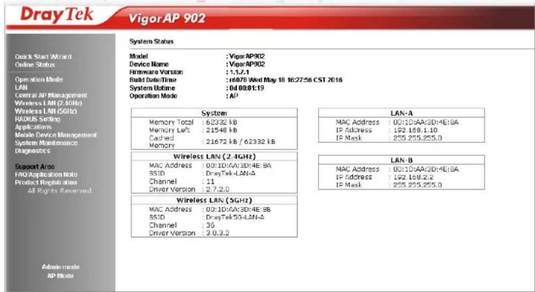
- Open a web browser on your PC and type http://192.168.1.2. The window will ask for typing username and password.
- Please type "admin/admin" on Username/Password for administration operation.
Now, the Main Screen will appear. Be aware that “Admin mode” will be displayed on the bottom left side.
text_image
DrayTek VigorAP 902 System Status Model : VigorAP902 Device Name : VigorAP902 Hirmware Version : 1.1.7.1 Build Date/Time : 16078 Wed May 18 16:27:56 CST 2016 System Uptime : 0d 00:01:19 Operation Mode : AP System Memory Total : 62332 kB Memory Left : 21548 kB Cached : 21672 kB / 62332 kB Memory LAN-A MAC Address : 00:1D:AA:3D:4E:BA IP Address : 192 168.1.10 IP Mask : 255.255.255.0 Wireless LAN (2.4GHz) MAC Address : 00:1D:AA:3D:4E:BA SSID : DrayTek-LAN-A Channel : 11 Driver Version : 2.7.2.0 LAN-B MAC Address : 00:1D:AA:3D:4E:BA IP Address : 192 168.2.2 IP Mask : 255.255.255.0 Wireless LAN (5GHz) MAC Address : 00:1D:AA:3D:4E:BB SSID : DrayTek5G-LAN-A Channel : 35 Driver Version : 3.0.3.2 Admin mode AP Mode3.1 Operation Mode
This page provides several available modes for you to choose for different conditions. Click any one of them and click OK. The system will configure the required settings automatically.
Operation Mode Configuration
Wireless LAN (2.4GHz)
AP:
VigorAP acts as a bridge between wireless devices and wired Ethernet network, and exchanges data between them.
Enable the Ethernet device as a wireless station and join a wireless network through an AP.
○ AP Bridge-Point to Point :
VigorAP will connect to another VigorAP which uses the same mode, and all wired Ethernet clients of both VigorAPs will be connected together.
○ AP Bridge-Point to Multi-Point :
VigorAP will connect to up to four VigorAPs which uses the same mode, and all wired Ethernet clients of every VigorAPs will be connected together.
AP Bridge-WDS :
VigorAP will connect to up to four VigorAPs which uses the same mode, and all wired Ethernet clients of every VigorAPs will be connected together. This mode is still able to accept wireless clients.
○ Universal Repeater :
VigorAP can act as a wireless repeater; it can be Station and AP at the same time.
Wireless LAN (5GHz)
AP:
VigorAP acts as a bridge between wireless devices and wired Ethernet network, and exchanges data between them.
○ Universal Repeater :
VigorAP can act as a wireless repeater; it can be Station and AP at the same time.
OK
Available settings are explained as follows:
| Item | Description |
| Wireless LAN(2.4GHz) | |
| AP | This mode allows wireless clients to connect to access point and exchange data with the devices connected to the wired network. |
| Station-Infrastructure | Enable the Ethernet device such as TV and Game player connected to the VigorAP 902 to an access point. |
| AP Bridge-Point to Point | This mode can establish wireless connection with another VigorAP 902 using the same mode, and link the wired network which these two VigorAP 902s connected together. Only one access point can be connected in this mode. |
| AP Bridge-Point to Multi-Point | This mode can establish wireless connection with other VigorAP 902s using the same mode, and link the wired network which these VigorAP 902s connected together. Up to 4 access points can be connected in this mode. |
| AP Bridge-WDS | This mode is similar to AP Bridge to Multi-Point, but access point is not working in bridge-dedicated mode, and will be able to accept wireless clients while the access point is working as awireless bridge. |
| Universal Repeater | This product can act as a wireless range extender that will help you to extend the networking wirelessly. The access point can act as Station and AP at the same time. It can use Station function to connect to a Root AP and use AP function to service all wireless clients within its coverage. |
| Wireless LAN(5GHz) | |
| AP | This mode allows wireless clients to connect to access point and exchange data with the devices connected to the wired network. |
| Universal Repeater | This product can act as a wireless range extender that will help you to extend the networking wirelessly. The access point can act as Station and AP at the same time. It can use Station function to connect to a Root AP and use AP function to service all wireless clients within its coverage. |
Note: The Wireless LAN settings will be changed according to the Operation Mode selected here. For the detailed information, please refer to the section of Wireless LAN.
3.2 LAN
Local Area Network (LAN) is a group of subnets regulated and ruled by modem.
LAN
General Setup
Port Control
3.2.1 General Setup
Click LAN to open the LAN settings page and choose General Setup.
Note: Such page will be changed according to the Operation Mode selected. The following screen is obtained by choosing AP as the operation mode.
Ethernet TCP / IP and DHCP Setup
| LAN-A IP Network ConfigurationEnable DHCP ClientIP Address 192.168.1.2Subnet Mask 255.255.255.0Default GatewayEnable Management VLANVLAN ID 0 | DHCP Server ConfigurationEnable Server Disable ServerRelay AgentStart IP AddressEnd IP AddressSubnet MaskDefault GatewayLease Time 86400DHCP Server IPAddress for Relay AgentPrimary DNS ServerSecondary DNS Server |
| LAN-B IP Network ConfigurationEnable DHCP ClientIP Address 192.168.2.2Subnet Mask 255.255.255.0Enable Management VLANVLAN ID 0 | DHCP Server ConfigurationEnable Server Disable ServerRelay AgentStart IP AddressEnd IP AddressSubnet MaskDefault GatewayLease Time 86400DHCP Server IPAddress for Relay AgentPrimary DNS ServerSecondary DNS Server |

Available settings are explained as follows:
| Item | Description |
| LAN-A IP Network Configuration | Enable DHCP Client – When it is enabled, VigorAP 902 will be treated as a client and can be managed / controlled by AP Management server offered by Vigor router (e.g., Vigor2860).IP Address – Type in private IP address for connecting to a local private network (Default: 192.168.1.2).Subnet Mask – Type in an address code that determines the size of the network. (Default: 255.255.255.0/ 24)Default Gateway – In general, it is not really necessary to specify a gateway for VigorAP 902. However, if it is required, simply type an IP address as the gateway for VigorAP 902. It will be convenient for the access point to acquire more service (e.g., accessing NTP server) from Vigor router.Enable Management VLAN – VigorAP 902 supports tag-based VLAN for wireless clients accessing Vigor device. Only the clients with the specified VLAN ID can access into VigorAP 902.VLAN ID – Type the number as VLAN ID tagged on the transmitted packet. “0” means no VALN tag. |
| LAN-B IP Network | IP Address – Type in private IP address for connecting to a local |
| Configuration | private network (Default: 192.168.2.2).Subnet Mask - Type in an address code that determines the size of the network. (Default: 255.255.255.0/ 24)Enable Management VLAN - VigorAP 902 supports tag-based VLAN for wireless clients accessing Vigor device. Only the clients with the specified VLAN ID can access into VigorAP 902.VLAN ID - Type the number as VLAN ID tagged on the transmitted packet. “0” means no VALN tag. |
| DHCP Server Configuration | DHCP stands for Dynamic Host Configuration Protocol. DHCP server can automatically dispatch related IP settings to any local user configured as a DHCP client.Enable Server / Disable Server - Enable Server lets the modem assign IP address to every host in the LAN期間Disable Server lets you manually or use other DHCP server to assign IP address to every host in the LAN.Relay Agent - Specify which subnet that DHCP server is located the relay agent should redirect the DHCP request to.Start IP Address - Enter a value of the IP address pool for the DHCP server to start with when issuing IP addresses. If the 1st IP address of your modem is 192.168.1.2, the starting IP address must be 192.168.1.3 or greater, but smaller than 192.168.1.254.End IP Address - Enter a value of the IP address pool for the DHCP server to end with when issuing IP addresses.Subnet Mask -Type in an address code that determines the size of the network. (Default: 255.255.255.0/ 24)Default Gateway - Enter a value of the gateway IP address for the DHCP server.Lease Time - It allows you to set the leased time for the specified PC.DHCP Server IP Address for Relay Agent - It is available when Enable Relay Agent is selected. Set the IP address of the DHCP server you are going to use so the Relay Agent can help to forward the DHCP request to the DHCP server.Primary IP Address - You must specify a DNS server IP address here because your ISP should provide you with usually more than one DNS Server. If your ISP does not provide it, the modem will automatically apply default DNS Server IP address: 194.109.6.66 to this field.Secondary IP Address - You can specify secondary DNS server IP address here because your ISP often provides you more than one DNS Server. If your ISP does not provide it, the modem will automatically apply default secondary DNS Server IP address: 194.98.0.1 to this field. |
After finishing this web page configuration, please click OK to save the settings.
3.2.2 Port Control
To avoid wrong connection due to the insertion of unsuitable Ethernet cable, the function of physical LAN ports can be disabled via web configuration.
LAN >> Port Control
Port Control

text_image
Enable Port Control LAN-B LAN-A4 LAN-A3(PoE) LAN-A2 LAN-A1 Disable Port OK Clear CancelAvailable settings are explained as follows:
| Item | Description |
| Enable Port Control | Check it to enable the port control. If it is enabled, you are allowed to disable the function of physical LAN port by checking the corresponding check box. |
| Disable Port | Choose and check the LAN port. |
After finishing this web page configuration, please click OK to save the settings.
3.3 Central AP Management
Such menu allows you to configure VigorAP device to be managed by Vigor router.
Central AP Management
General Setup
APM Log
Function Support List
Overload Management
Status of Settings
3.3.1 General Setup
Central AP Management >> General Setup
Vigor AP Manegemet
Enable AP Management
Enable Auto Provision

Note: LAN-B cannot support APM feature.
Available settings are explained as follows:
| Item | Description |
| Enable AP Management | Check the box to enable the function of AP Management (APM). |
| Enable Auto Provision | VigorAP 902 can be controlled under Central AP Management in Vigor2860 series. When both Vigor2860 series and VigorAP 902 have such feature enabled, once VigorAP 902 is registered to Vigor2860 series, the WLAN profile pre-configured on Vigor2860 series will be applied to VigorAP 902 immediately. Thus, it is not necessary to configure VigorAP 902 separately. |
3.3.2 APM Log
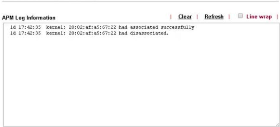
This page will display log information related to wireless stations connected to VigorAP 902 and central AP management.
Such information also will be delivered to Vigor router (e.g., Vigor2860 or Vigor2925 series) and be shown on Central AP Management>>Event Log of Vigor router.
Central AP Management >> APM Log
text_image
APM Log Information | Clear | Refresh | Line wrap | 1d 17:42:35 kernel: 20:02:af:a5:67:22 had associated successfully 1d 17:42:35 kernel: 20:02:af:a5:67:22 had disassociated.3.3.3 Function Support List
Click the Client tab to list the AP management functions that the Access Points support under different firmware versions.
Central AP Management >> Function Support List
| Client | |
| Model Name | |
| Function Name | AP902 |
| 1.1.5 | |
| Register | |
| DHCP | V |
| Static IP | V |
| Profile | |
| 2.4GHz | V |
| 5GHz | V |
| AP Mode | V |
| Repeater Mode | V |
| Client Disable Auto Provision | V |
| WLAN Enable/Disable | V |
| Station List | |
| Station List | V |
Note: DrayTek central wireless management (AP Management) lets control, efficiency, monitoring and security of your company-wide wireless access easier to be managed. Inside the web user interface, we call “central wireless management” as Central AP Management which supports mobility, client monitoring/reporting and load-balancing to multiple APs. For central wireless management, you will need a Vigor2860 or Vigor2925 series router; there is no per-node licensing or subscription required. With the unified user interface of Vigor2860 Combo WAN series and Vigor2925 Triple WAN series, the multiple deployment of VigorAP 902 can be clear at the first sight. For multiple wireless clients, to apply the AP Load Balancing to the multiple APs will manage wireless traffic with smooth flow and enhanced efficiency.
3.3.4 Overload Management
Load Balance can help to distribute the traffic for all of the access points (e.g., VigorAP 902) registered to Vigor router. Thus, the bandwidth will not be occupied by certain access points.
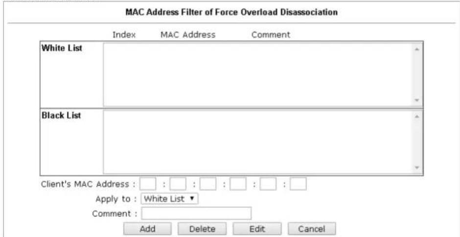
However, traffic overload might be occurred if too many wireless stations connected to VigorAP 902 for data incoming and outgoing. Therefore, “Force Overload Disassociation” is required to terminate the network connection of the client’s station to release network traffic. When the function of “Force Overload Disassociation” in web user interface of Vigor router (e.g., Vigor2860 or Vigor2925 series) is enabled, wireless clients specified in black list of such web page will be disassociated to solve the problem of traffic overload.
The following web page is used to configure white list and black list for wireless stations.
Central AP Management >> Overload Management
Overload Management
text_image
MAC Address Filter of Force Overload Disassociation Index MAC Address Comment White List Black List Client's MAC Address : □ : □ : □ : □ : □ : □ : □ Apply to : White List ▼ Comment : Add Delete Edit CancelNote: When force overload disassociation is enabled, clients in black list will be disassociated first. Clients in white list will not be disassociated.

Available settings are explained as follows:
| Item | Description |
| White List/Black List | Display the information (such as index number, MAC address and comment) for all of the members in White List/Black List.Wireless stations listed in Black List will be forcefully disconnected first when traffic overload occurs and “Force Overload Disassociation” is enabled. |
| Client’s MAC | Specify the MAC Address of the remote/local client. |
| Address | |
| Apply to | White List – MAC address listed inside Client’s MAC Address will be categorized as one of members in White List.Black List - MAC address listed inside Client’s MAC Address will be categorized as one of members in Black List. |
| Add | Add a new MAC address into the White List/Black List. |
| Delete | Delete the selected MAC address in the White List/Black List. |
| Edit | Edit the selected MAC address in the White List/Black List. |
| Cancel | Give up the configuration. |
3.3.5 Status of Settings
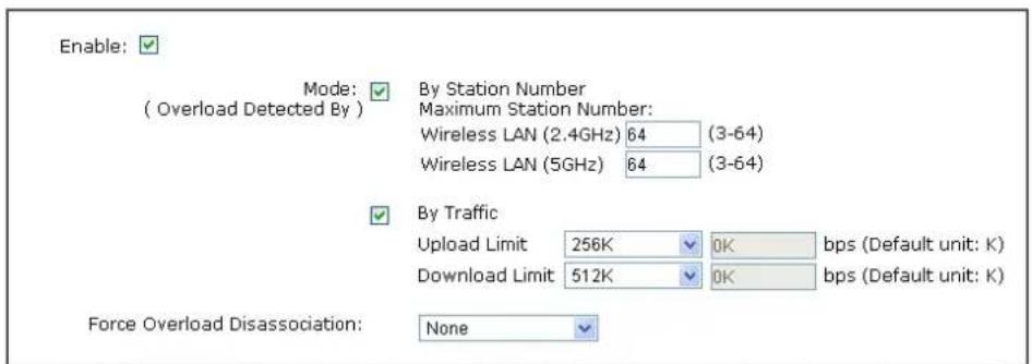
Load Balance can help to distribute the traffic for all of the access points (e.g., VigorAP 902s) registered to Vigor 2860 or Vigor2925 series. This web page displays the settings related to Load Balance for VigorAP 902. In which, By Station Number, By Traffic and Force Overload Disassociation indicate settings configured in Vigor 2860 or Vigor2925 series.
Central AP Management >> Status of Settings
| Function Name | Status | Value |
| Load Balance | ||
| By Station Number | ✕ | |
| Max WLAN(2.4GHz) Station Number | 64 | |
| Max WLAN(5GHz) Station Number | 64 | |
| By Traffic | ✕ | |
| Upload Limit | None | |
| Download Limit | None | |
| Force Overload Disassociation | ✕ | |
| Force Overload Disassociation By | None | |
| RSSI Threshold | -50 | |
| Rogue AP Detection | ||
| Rogue AP Detection | ✕ | |
“X” means the function is not enabled or VigorAP 902 has not registered to any Vigor router yet.
Below shows a setting example for Load Balance settings configured in Vigor 2860 or Vigor2925 series.
Central AP Management >> Load Balance
text_image
Enable: Mode: By Station Number ( Overload Detected By ) Maximum Station Number: Wireless LAN (2.4GHz) 64 (3-64) Wireless LAN (5GHz) 64 (3-64) By Traffic Upload Limit 256K 0K bps (Default unit: K) Download Limit 512K 0K bps (Default unit: K) Force Overload Disassociation: NoneNote: The maximum station number of Wireless LAN (2.4GHz) will be applied to both Wireless LAN (2.4GHz) and Wireless LAN (5GHz) if the firmware version of AP900 is less than or equal to 1.1.4.1.

3.4 General Concepts for Wireless LAN (2.4GHz/5GHz)
VigorAP 902 is a highly integrated wireless local area network (WLAN) for 5 GHz 802.11ac or 2.4/5 GHz 802.11n WLAN applications. It supports channel operations of 20/40 MHz at 2.4 GHz and 20/40/80 MHz at 5 GHz. VigorAP 902 can support data rates up to 867 MBps in 802.11ac 80 MHz channels.
Note: * The actual data throughput will vary according to the network conditions and environmental factors, including volume of network traffic, network overhead and building materials.
In an Infrastructure Mode of wireless network, VigorAP 902 plays a role as an Access Point (AP) connecting to lots of wireless clients or Stations (STA). All the STAs will share the same Internet connection via VigorAP 902. The General Setup will set up the information of this wireless network, including its SSID as identification, located channel etc.
Security Overview
WEP (Wired Equivalent Privacy) is a legacy method to encrypt each frame transmitted via radio using either a 64-bit or 128-bit key. Usually access point will preset a set of four keys and it will communicate with each station using only one out of the four keys.
WPA (Wi-Fi Protected Access), the most dominating security mechanism in industry, is separated into two categories: WPA-personal or called WPA Pre-Share Key (WPA/PSK), and WPA-Enterprise or called WPA/802.1x.
In WPA-Personal, a pre-defined key is used for encryption during data transmission. WPA applies Temporal Key Integrity Protocol (TKIP) for data encryption while WPA2 applies AES. The WPA-Enterprise combines not only encryption but also authentication.
Since WEP has been proved vulnerable, you may consider using WPA for the most secure connection. You should select the appropriate security mechanism according to your needs. No matter which security suite you select, they all will enhance the over-the-air data protection and/or privacy on your wireless network. The VigorAP 902 is very flexible and can support multiple secure connections with both WEP and WPA at the same time.
WPS Introduction
WPS (Wi-Fi Protected Setup) provides easy procedure to make network connection between wireless station and wireless access point (VigorAP 902) with the encryption of WPA and WPA2.
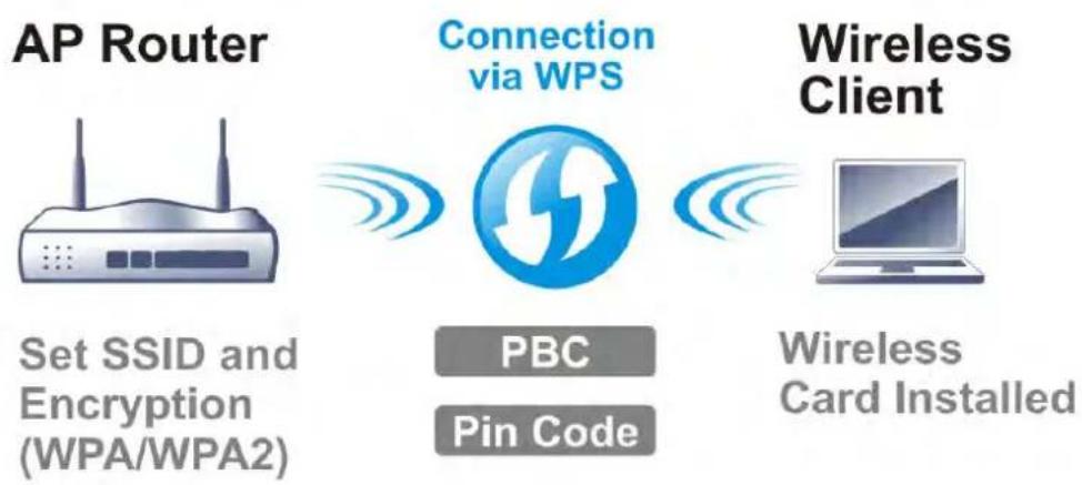
flowchart
graph LR
    A["AP Router"] --> B["Connection via WPS"]
    B --> C["Wireless Client"]
    D["Set SSID and Encryption (WPA/WPA2)"] --> B
    E["PBC"] --> B
    F["Pin Code"] --> B
    G["Wireless Card Installed"] --> C
It is the simplest way to build connection between wireless network clients and VigorAP 902. Users do not need to select any encryption mode and type any long encryption passphrase to setup a wireless client every time. He/she only needs to press a button on wireless client, and WPS will connect for client and VigorAP 902 automatically.
Note: Such function is available for the wireless station with WPS supported.
There are two methods to do network connection through WPS between AP and Stations: pressing the Start PBC button or using PIN Code.
On the side of VigorAP 902 series which served as an AP, press WPS button once on the front panel of VigorAP 902 or click Start PBC on web configuration interface. On the side of a station with network card installed, press Start PBC button of network card.
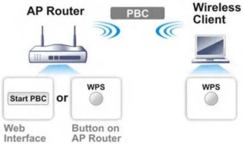
flowchart
graph TD
    A["AP Router"] -->|PBC| B["Wireless Client"]
    B -->|WPS| C["Start PBC or Web Interface"]
    C --> D["Button on AP Router"]
    D --> E["WPS"]
If you want to use PIN code, you have to know the PIN code specified in wireless client. Then provide the PIN code of the wireless client you wish to connect to the VigorAP 902.
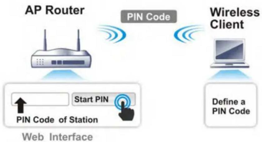
flowchart
graph TD
    A["AP Router"] -->|Start PIN| B["PIN Code of Station"]
    B --> C["Web Interface"]
    D["Wireless Client"] -->|Define a PIN Code| E["Laptop"]
    style A fill:#f9f,stroke:#333
    style D fill:#ccf,stroke:#333
    style B fill:#cfc,stroke:#333
    style E fill:#fcc,stroke:#333
3.5 Wireless LAN Settings for AP Mode
When you choose AP as the operation mode, the Wireless LAN menu items will include General Setup, Security, Access Control, WPS, AP Discovery, WMM Configuration, Station List, Bandwidth Management, Airtime Fairness, Roaming, Status and Station Control.
Wireless LAN (2.4GHz)
General Setup
Security
Access Control
WPS
Advanced Setting
AP Discovery
WMM Configuration
Bandwidth Management
Airtime Fairness
Station Control
Roaming
Band Steering
Station List
Note: The Wireless LAN settings will be changed according to the Operation Mode selected in section 3.1.
3.5.1 General Setup
By clicking the General Setup, a new web page will appear so that you could configure the SSID and the wireless channel. Please refer to the following figure for more information.
Wireless LAN (2.4GHz) >> General Setup
General Setting ( IEEE 802.11 )
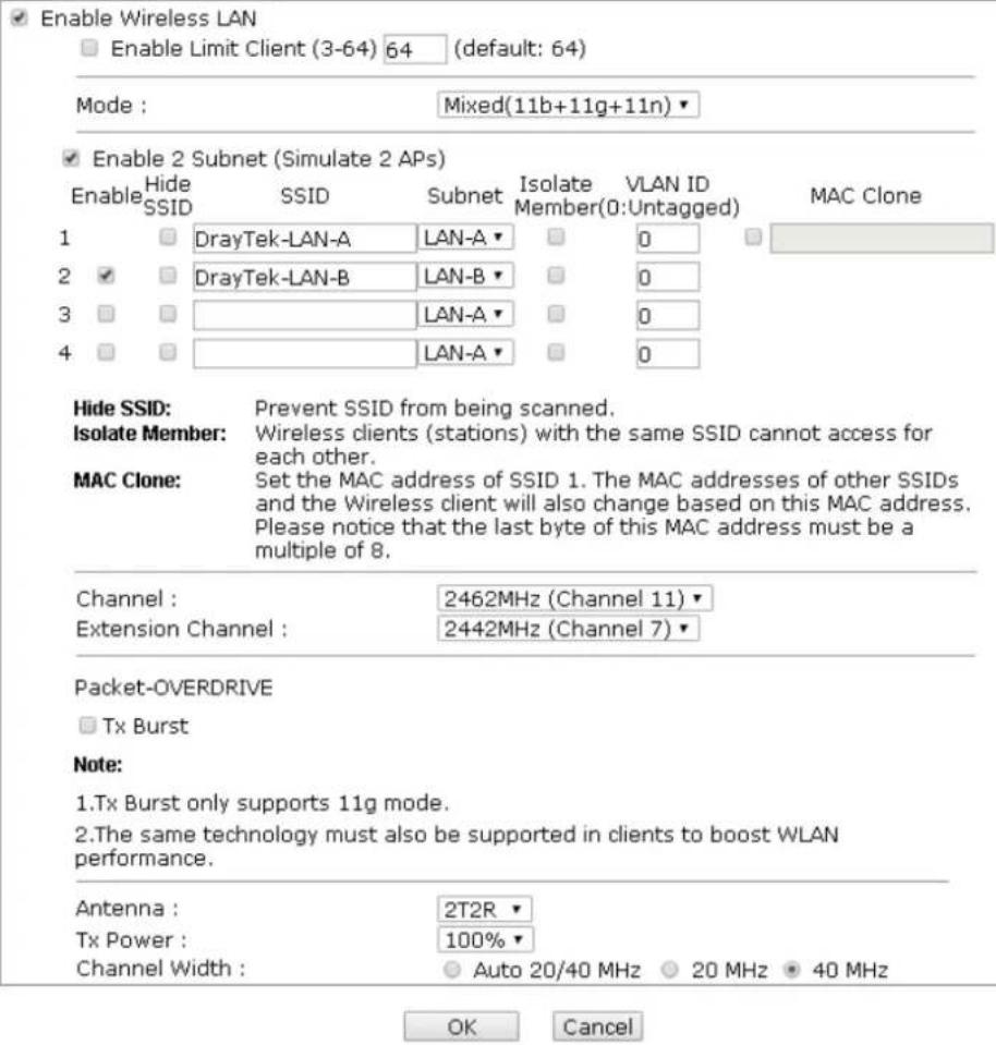
text_image
Enable Wireless LAN Enable Limit Client (3-64) 64 (default: 64) Mode : Mixed(11b+11g+11n) Enable 2 Subnet (Simulate 2 APs) Enable Hide SSID SSID Subnet Isolate Member(VLAN ID: Untagged) MAC Clone 1 DrayTek-LAN-A LAN-A 0 2 DrayTek-LAN-B LAN-B 0 3 LAN-A 0 4 LAN-A 0 Hide SSID: Prevent SSID from being scanned. Isolate Member: Wireless clients (stations) with the same SSID cannot access for each other. MAC Clone: Set the MAC address of SSID 1. The MAC addresses of other SSIDs and the Wireless client will also change based on this MAC address. Please notice that the last byte of this MAC address must be a multiple of 8. Channel : 2462MHz (Channel 11) Extension Channel : 2442MHz (Channel 7) Packet-OVERDRIVE Tx Burst Note: 1.Tx Burst only supports 11g mode. 2.The same technology must also be supported in clients to boost WLAN performance. Antenna : 2T2R Tx Power : 100% Channel Width : Auto 20/40 MHz 20 MHz 40 MHz OK CancelAvailable settings are explained as follows:
| Item | Description |
| Enable Wireless LAN | Check the box to enable wireless function. |
| Enable Limit Client | Check the box to set the maximum number of wireless stations which try to connect Internet through Vigor device. The number you can set is from 3 to 64. |
| Mode | At present, VigorAP 902 can connect to 11b only, 11g only, 11n only, Mixed (11b+11g), Mixed (11g+11n) and Mixed (11b+11g+11n) stations simultaneously. Simply choose Mixed (11b+11g+11n) mode.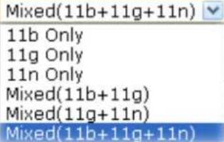 |
| Enable 2 Subnet(Simulate 2 APs) | Check the box to enable the function for two independent subnets. Once you enable this function, LAN-A and LAN-B would be independent. Next, you can connect one router in LAN-A, and another router in LAN-B. Such mechanism can make you feeling that you have two independent AP/subnet functions in one VigorAP 902.If you disable this function, LAN-A and LAN-B ports are in the same domain. You could only connect one router (no matter connecting to LAN-A or LAN-B) in this environment. |
| Hide SSID | Check it to prevent from wireless sniffing and make it harder for unauthorized clients or STAs to join your wireless LAN. Depending on the wireless utility, the user may only see the information except SSID or just cannot see any thing about VigorAP 902 while site surveying. The system allows you to set four sets of SSID for different usage. |
| SSID | Set a name for VigorAP 902 to be identified. Default settings are DrayTek-LAN-A and DrayTek-LAN-B. When Enable 2 Subnet is enabled, you can specify subnet interface (LAN-A or LAN-B) for each SSID by using the drop down menu. |
| Subnet | Choose LAN-A or LAN-B for each SSID. If you choose LAN-A, the wireless clients connecting to this SSID could only communicate with LAN-A. |
| Isolate Member | Check this box to make the wireless clients (stations) with the same SSID not access for each other. |
| VLAN ID | Type the value for such SSID. Packets transferred from such SSID to LAN will be tagged with the number.If your network uses VLANs, you can assign the SSID to a VLAN on your network. Client devices that associate using the SSID are grouped into this VLAN. The VLAN ID range is from 3 to 4095. The VLAN ID is 0 by default, it means disabling the VLAN function for the SSID. |
| MAC Clone | Check this box and manually enter the MAC address of the device with SSID 1. The MAC address of other SSIDs will change based on this MAC address. |
| Channel | Means the channel of frequency of the wireless LAN. You may switch channel if the selected channel is under serious interference. If you have no idea of choosing the frequency, please selectAutoSelectto let system determine for you. |
| Extension Channel | With 802.11n, there is one option to double the bandwidth per channel. The available extension channel options will be variedaccording to the Channel selected above. Configure the extension channel you want. |
| Rate | If you choose 11g Only, 11b Only, 11n Only, or Mixed (11b+11g), such feature will be available for you to set data transmission rate. |
| Packet-OVERDRIVE | This feature can enhance the performance in data transmission about 40%* more (by checking Tx Burst). It is active only when both sides of Access Point and Station (in wireless client) invoke this function at the same time. That is, the wireless client must support this feature and invoke the function, too.Note:Vigor N61 wireless adapter supports this function. Therefore, you can use and install it into your PC for matching with Packet-OVERDRIVE (refer to the following picture of Vigor N61 wireless utility window, choose Enable for TxBURST on the tab of Option).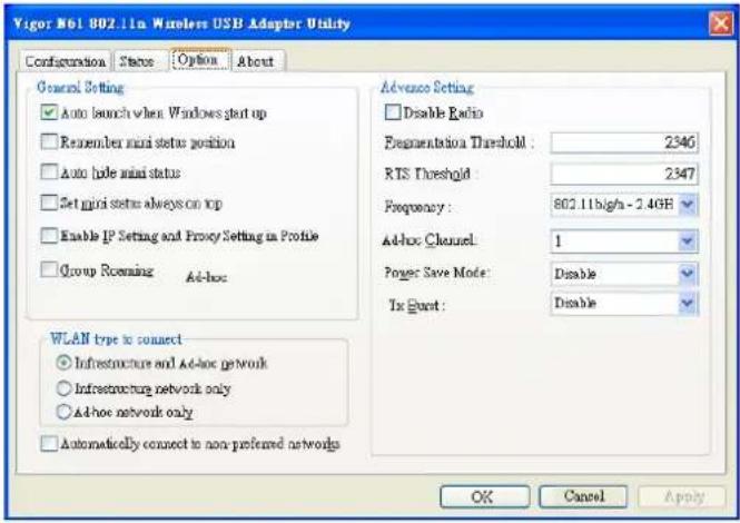 |
| Antenna | VigorAP 902 can be attached with two antennas to have good data transmission via wireless connection. However, if you have only one antenna attached, please choose 1T1R.[2T2R2T2R1T1R] |
| Tx Power | The default setting is the maximum (100%). Lowering down the value may degrade range and throughput of wireless.[100%100%80%60%30%20%10%] |
| Channel Width | Auto 20/40 MHZ- the device will use 20Mhz or 40Mhz for data transmission and receiving according to the station capability. Such channel can increase the performance for data transmission.20 MHZ- the device will use 20Mhz for data transmission and receiving between the AP and the stations.40 MHZ- the device will use 40Mhz for data transmission and receiving between the AP and the stations. |
After finishing this web page configuration, please click OK to save the settings.
3.5.2 Security
This page allows you to set security with different modes for SSID 1, 2, 3 and 4 respectively. After configuring the correct settings, please click OK to save and invoke it.
By clicking the Security Settings, a new web page will appear so that you could configure the settings.
Wireless LAN (2.4GHz) >> Security Settings
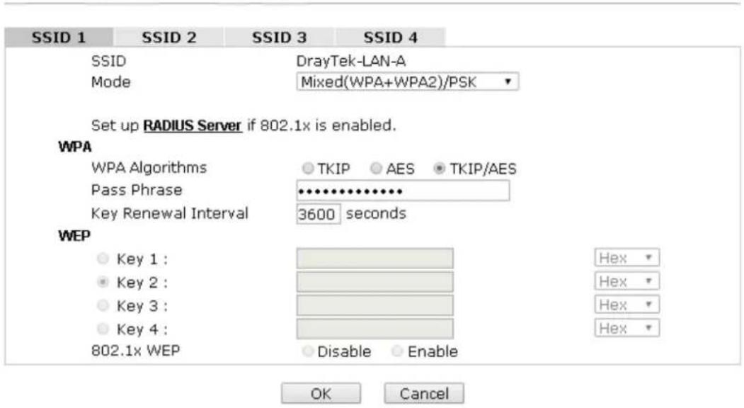
text_image
SSID 1 SSID 2 SSID 3 SSID 4 SSID DrayTek-LAN-A Mode Mixed(WPA+WPA2)/PSK Set up RADIUS Server if 802.1x is enabled. WPA WPA Algorithms ○ TKIP ○ AES ● TKIP/AES Pass Phrase ••••••••••••• Key Renewal Interval 3600 seconds WEP ● Key 1 : ● Key 2 : ● Key 3 : ● Key 4 : 802.1x WEP ● Disable ○ Enable Hex Hex Hex Hex OK CancelAvailable settings are explained as follows:
| Item | Description |
| Mode | There are several modes provided for you to choose. |
| Disable | |
| Disable | |
| WEP | |
| WPA/PSK | |
| WPA2/PSK | |
| Mixed(WPA+WPA2)/PSK | |
| WEP/802.1x | |
| WPA/802.1x | |
| WPA2/802.1x | |
| Mixed(WPA+WPA2)/802.1x | |
| Disable - The encryption mechanism is turned off. | |
| WEP - Accepts only WEP clients and the encryption key should be entered in WEP Key. | |
| WPA/PSK or WPA2/PSK or Mixed (WPA+WPA2)/PSK - Accepts only WPA clients and the encryption key should be entered in PSK. The WPA encrypts each frame transmitted | |
| from the radio using the key, which either PSK (Pre-Shared Key) entered manually in this field below or automatically negotiated via 802.1x authentication.WEP/802.1x - The built-in RADIUS client feature enables VigorAP 902 to assist the remote dial-in user or a wireless station and the RADIUS server in performing mutual authentication. It enables centralized remote access authentication for network management.The WPA encrypts each frame transmitted from the radio using the key, which either PSK (Pre-Shared Key) entered manually in this field below or automatically negotiated via 802.1x authentication. Select WPA, WPA2 or Auto as WPA mode.WPA/802.1x - The WPA encrypts each frame transmitted from the radio using the key, which either PSK (Pre-Shared Key) entered manually in this field below or automatically negotiated via 802.1x authentication.WPA2/802.1x - The WPA encrypts each frame transmitted from the radio using the key, which either PSK (Pre-Shared Key) entered manually in this field below or automatically negotiated via 802.1x authentication. | |
| WPA Algorithms | Select TKIP, AES or TKIP/AES as the algorithm for WPA. Such feature is available for WPA2/802.1x, WPA/802.1x, WPA/PSK or WPA2/PSK or Mixed (WPA+WPA2)/PSK mode. |
| Pass Phrase | Either 8~63 ASCII characters, such as 012345678..(or 64 Hexadecimal digits leading by 0x, such as "0x321253abcde..."). Such feature is available for WPA/PSK or WPA2/PSK or Mixed (WPA+WPA2)/PSK mode. |
| Key Renewal Interval | WPA uses shared key for authentication to the network. However, normal network operations use a different encryption key that is randomly generated. This randomly generated key that is periodically replaced. Enter the renewal security time (seconds) in the column. Smaller interval leads to greater security but lower performance. Default is 3600 seconds. Set 0 to disable re-key. Such feature is available for WPA2/802.1,WPA/802.1x, WPA/PSK or WPA2/PSK or Mixed (WPA+WPA2)/PSK mode. |
| Key 1 - Key 4 | Four keys can be entered here, but only one key can be selected at a time. The format of WEP Key is restricted to 5 ASCII characters or 10 hexadecimal values in 64-bit encryption level, or restricted to 13 ASCII characters or 26 hexadecimal values in 128-bit encryption level. The allowed content is the ASCII characters from 33(!) to 126(~) except '#' and '.'. Such feature is available for WEP mode.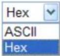 |
| 802.1x WEP | Disable - Disable the WEP Encryption. Data sent to the APwill not be encrypted. Enable - Enable the WEP Encryption. Such feature is available for WEP/802.1x mode. |
Click the link of RADIUS Server to access into the following page for more settings.
RADIUS Server
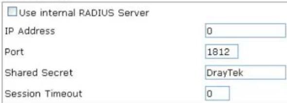
text_image
Use internal RADIUS Server IP Address 0 Port 1812 Shared Secret DrayTek Session Timeout 0
Available settings are explained as follows:
| Item | Description |
| Use internal RADIUS Server | There is a RADIUS server built in VigorAP 902 which is used to authenticate the wireless client connecting to the access point. Check this box to use the internal RADIUS server for wireless security.Besides, if you want to use the external RADIUS server for authentication, do not check this box.Please refer to the section,3.12 RADIUS Server to configure settings for internal server of VigorAP 902. |
| IP Address | Enter the IP address of external RADIUS server. |
| Port | The UDP port number that the external RADIUS server is using. The default value is 1812, based on RFC 2138. |
| Shared Secret | The external RADIUS server and client share a secret that is used to authenticate the messages sent between them. Both sides must be configured to use the same shared secret. |
| Session Timeout | Set the maximum time of service provided before re-authentication. Set to zero to perform another authentication immediately after the first authentication has successfully completed. (The unit is second.) |
After finishing this web page configuration, please click OK to save the settings.
3.5.3 Access Control
For additional security of wireless access, the Access Control facility allows you to restrict the network access right by controlling the wireless LAN MAC address of client. Only the valid MAC address that has been configured can access the wireless LAN interface. By clicking the Access Control, a new web page will appear, as depicted below, so that you could edit the clients' MAC addresses to control their access rights (deny or allow).
Wireless LAN (2.4GHz) >> Access Control
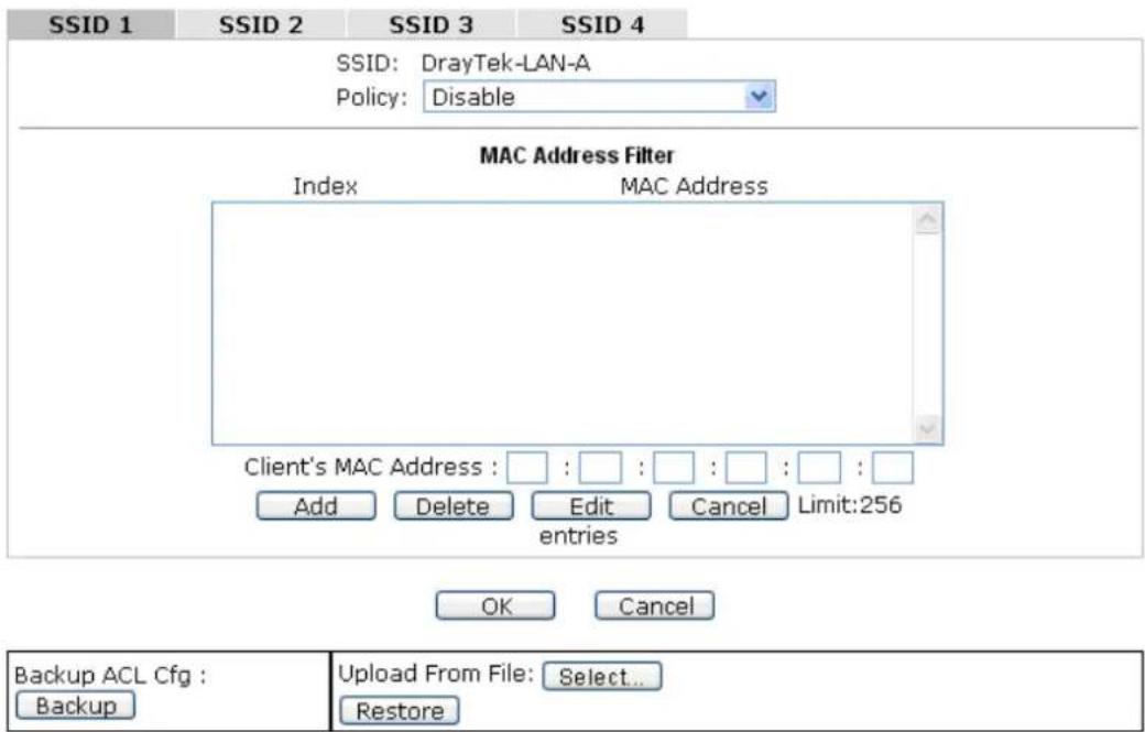
text_image
SSID 1 SSID 2 SSID 3 SSID 4 SSID: DrayTek-LAN-A Policy: Disable MAC Address Filter Index MAC Address Client's MAC Address : : : : : : : : Add Delete Edit Cancel Limit:256 entries OK Cancel Backup ACL Cfg : Backup Upload From File: Select... RestoreAvailable settings are explained as follows:
| Item | Description |
| Policy | Select to enable any one of the following policy or disable the policy.ChooseActivate MAC address filterto type in the MAC addresses for other clients in the network manually.ChooseBlocked MAC address filter,so that all of the devices with the MAC addresses listed on the MAC Address Filter table will be blocked and cannot access into VigorAP 902.Activate MAC address filterDisableActivate MAC address filterBlocked MAC address filter |
| MAC Address Filter | Display all MAC addresses that are edited before. |
| Client's MAC Address | Manually enter the MAC address of wireless client. |
| Add | Add a new MAC address into the list. |
| Delete | Delete the selected MAC address in the list. |
| Edit | Edit the selected MAC address in the list. |
| Cancel | Give up the access control set up. |
| Backup | Click it to store the settings (MAC addresses on MAC Address Filter table) on this page as a file. |
| Restore | Click it to restore the settings (MAC addresses on MAC Address Filter table) from an existed file. |
After finishing this web page configuration, please click OK to save the settings.
3.5.4 WPS
Open Wireless LAN>>WPS to configure the corresponding settings.
Wireless LAN (2.4GHz) >> WPS (Wi-Fi Protected Setup)
Enable WPS
Wi-Fi Protected Setup Information
| WPS Configured | Yes |
| WPS SSID | DrayTek-LAN-A |
| WPS Auth Mode | Mixed(WPA+WPA2)/PSK |
| WPS Encryp Type | TKIP/AES |
Device Configure
| Configure via Push Button | Start PBC | |
| Configure via Client PinCode | Start PIN |
Status: Not used
Note: WPS can help your wireless client automatically connect to the Access point.
: WPS is Disabled.
Q: WPS is Enabled.
: Waiting for WPS requests from wireless clients.
Available settings are explained as follows:
| Item | Description |
| Enable WPS | Check this box to enable WPS setting. |
| WPS Configured | Display related system information for WPS. If the wireless security (encryption) function of VigorAP 902 is properly configured, you can see ‘Yes’ message here. |
| WPS SSID | Display current selected SSID. |
| WPS Auth Mode | Display current authentication mode of the VigorAP 902. Only WPA2/PSK and WPA/PSK support WPS. |
| WPS Encryp Type | Display encryption mode (None, WEP, TKIP, AES, etc.) of VigorAP 902. |
| Configure via Push Button | Click Start PBC to invoke Push-Button style WPS setup procedure. VigorAP 902 will wait for WPS requests from wireless clients about two minutes. Both ACT and 2.4G WLAN LEDs on VigorAP 902 will blink quickly when WPS is in progress. It will return to normal condition after two minutes. (You need to setup WPS within two minutes) |
| Configure via Client PinCode | Type the PIN code specified in wireless client you wish to connect, and click Start PIN button. Both ACT and 2.4G WLAN LEDs on VigorAP 902 will blink quickly when WPSis in progress. It will return to normal condition after two minutes. (You need to setup WPS within two minutes). |
3.5.5 Advanced Setting
This page is to determine which algorithm will be selected for wireless transmission rate.
Wireless LAN (2.4GHz) >> Advanced Setting

text_image
Rate Adaptation Algorithm Fragment Length (256 - 2346) RTS Threshold (1 - 2347) Country Code New Old 2346 bytes 2347 bytes (Reference)
Available settings are explained as follows:
| Item | Description |
| Rate Adaptation Algorithm | Wireless transmission rate is adapted dynamically. Usually, performance of “new” algorithm is better than “old”. |
| Fragment Length | Set the Fragment threshold of wireless radio. Do not modify default value if you don’t know what it is, default value is 2346. |
| RTS Threshold | Minimize the collision (unit is bytes) between hidden stations to improve wireless performance.Set the RTS threshold of wireless radio. Do not modify default value if you don’t know what it is, default value is 2347. |
| Country Code | VigorAP broadcasts country codes by following the 802.11d standard. However, some wireless stations will detect / scan the country code to prevent conflict occurred. If conflict is detected, wireless station will be warned and is unable to make network connection. Therefore, changing the country code to ensure successful network connection will be necessary for some clients. |
3.5.6 AP Discovery
VigorAP 902 can scan all regulatory channels and find working APs in the neighborhood. Based on the scanning result, users will know which channel is clean for usage. Also, it can be used to facilitate finding an AP for a WDS link. Notice that during the scanning process (about 5 seconds), no client is allowed to connect to Vigor.
This page is used to scan the existence of the APs on the wireless LAN. Please click Scan to discover all the connected APs.
Wireless LAN (2.4GHz) >> Access Point Discovery
Access Point List


See Channel Statistics
Note: During the scanning process (about 5 seconds), no station is allowed to connect with the AP.
Each item is explained as follows:
| Item | Description |
| SSID | Display the SSID of the AP scanned by VigorAP 902. |
| BSSID | Display the MAC address of the AP scanned by VigorAP 902. |
| RSSI | Display the signal strength of the access point. RSSI is the abbreviation of Received Signal Strength Indication. |
| Channel | Display the wireless channel used for the AP that is scanned by VigorAP 902. |
| Encryption | Display the encryption mode for the scanned AP. |
| Authentication | Display the authentication type that the scanned AP applied. |
| Scan | It is used to discover all the connected AP. The results will be shown on the box above this button |
| Channel Statistics | It displays the statistics for the channels used by APs. |
Wireless LAN (2.4GHz) >> Access Point Discovery
Access Point List
| SSID | BSSID | RSSI | Channel | Encryption | Authentication |
| staffs_SF | 00:1d:aa:c5:59:40 | 81% | 1 | TKIP/AES | Mixed(WPA+WPA2)/PSK |
| staffs | 02:1d:aa:c5:59:40 | 86% | 1 | TKIP/AES | Mixed(WPA+WPA2)/PSK |
| guest_SF | 06:1d:aa:c5:59:40 | 86% | 1 | TKIP/AES | Mixed(WPA+WPA2)/PSK |
| Vigor2120-... | 00:1d:aa:9:c:f7:2c | 29% | 6 | TKIP/AES | Mixed(WPA+WPA2)/PSK |
| DrayTek | 00:1d:aa:55:66:88 | 39% | 6 | NONE | |
| DrayTek | 00:1d:aa:d7:ob:d0 | 24% | 6 | TKIP/AES | Mixed(WPA+WPA2)/PSK |
| DrayTek | 00:1d:aa:do:e0:88 | 39% | 6 | TKIP/AES | Mixed(WPA+WPA2)/PSK |
| staffs_802... | 02:1d:aa:7a:4d:24 | 60% | 8 | TKIP/AES | Mixed(WPA+WPA2) |
| DrayTek | 00:1d:aa:80:06:b8 | 44% | 11 | TKIP/AES | Mixed(WPA+WPA2)/PSK |
| v2860 PQC ... | 02:1d:aa:86:ba:d0 | 39% | 11 | AES | WPA2/PSK |
| 00:1d:aa:b6:1b:b0 | 86% | 11 | WEP | ||
| TEST_001 | 00:50:7f:52:2f:58 | 44% | 11 | TKIP/AES | Mixed(WPA+WPA2)/PSK |
| DrayTek-LA... | 02:1d:aa:9c:1f:b8 | 24% | 11 | TKIP/AES | Mixed(WPA+WPA2)/PSK |
| v2925 pqc ... | 00:1d:aa:7f:5d:8c | 39% | 11 | TKIP/AES | Mixed(WPA+WPA2)/PSK |
| V2132 PQC ... | 02:1d:aa:7c:5d:8c | 44% | 11 | NONE |
Scan
See Channel Statistics
Note: During the scanning process (about 5 seconds), no station is allowed to connect with the AP.
3.5.7 WMM Configuration
WMM is an abbreviation of Wi-Fi Multimedia. It defines the priority levels for four access categories derived from 802.1d (prioritization tabs). The categories are designed with specific types of traffic, voice, video, best effort and low priority data. There are four accessing categories - AC_BE, AC_BK, AC_VI and AC_VO for WMM.

text_image
WMM Configuration Set to Factory Default WMM Capable Enable Disable WMM Parameters of Access Point Aifsn CWMin CWMax Txop ACM AckPolicy AC_BE 3 15 63 0 □ □ AC_BK 7 15 102 0 □ □ AC_VI 1 7 15 94 □ □ AC_VO 1 3 7 47 □ □ WMM Parameters of Station Aifsn CWMin CWMax Txop ACM AC_BE 3 15 102 0 □ AC_BK 7 15 102 0 □ AC_VI 2 7 15 94 □ AC_VO 2 3 7 47 □
Available settings are explained as follows:
| Item | Description |
| WMM Capable | To apply WMM parameters for wireless data transmission, please click the Enable radio button. |
| Aifsn | It controls how long the client waits for each data transmission. Please specify the value ranging from 1 to 15. Such parameter will influence the time delay for WMM accessing categories. For the service of voice or video image, please set small value for AC_VI and AC_VO categories For the service of e-mail or web browsing, please set large value for AC_BE and AC_BK categories. |
| CWMin/CWMax | CWMin means contention Window-Min and CWMax means contention Window-Max. Please specify the value ranging from 1 to 15. Be aware that CWMax value must be greater than CWMin or equals to CWMin value. Both values will influence the time delay for WMM accessing categories. The difference between AC_VI and AC_VO categories must be smaller; however, the difference between AC_BE and AC_BK categories must be greater. |
| Txop | It means transmission opportunity. For WMM categories of AC_VI and AC_VO that need higher priorities in data transmission, please set greater value for them to get highest transmission opportunity. Specify the value ranging from 0 to 65535. |
| ACM | It is an abbreviation of Admission control Mandatory. It can restrict stations from using specific category class if it is checked.Note: VigorAP 902 provides standard WMM configuration in the web page. If you want to modify the parameters, please refer to the Wi-Fi WMM standard specification. |
| AckPolicy | “Uncheck” (default value) the box means the AP will answer theresponse request while transmitting WMM packets through wireless connection. It can assure that the peer must receive the WMM packets.“Check” the box means the AP will not answer any response request for the transmitting packets. It will have better performance with lower reliability. |
After finishing this web page configuration, please click OK to save the settings.
3.5.8 Bandwidth Management
The downstream or upstream from FTP, HTTP or some P2P applications will occupy large of bandwidth and affect the applications for other programs. Please use Bandwidth Management to make the bandwidth usage more efficient.
Wireless LAN (2.4GHz) >> Bandwidth Management
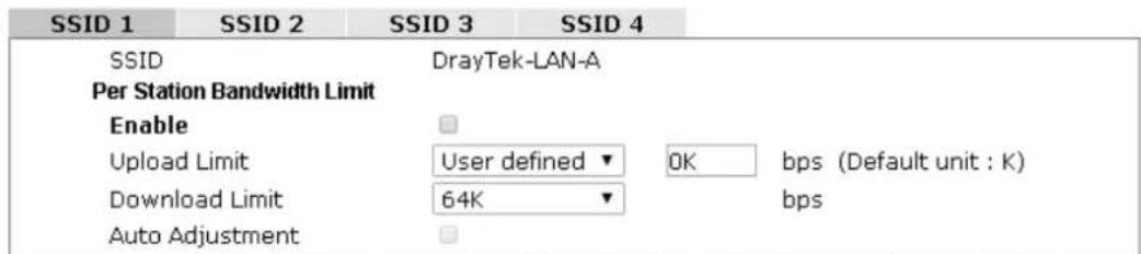
text_image
SSID 1 SSID 2 SSID 3 SSID 4 SSID DrayTek-LAN-A Per Station Bandwidth Limit Enable Upload Limit User defined ▼ OK bps (Default unit : K) Download Limit 64K bps Auto AdjustmentNote: 1. Download : Traffic going to any station. Upload : Traffic being sent from a wireless station. 2. Allow auto adjustment could make the best utilization of available bandwidth.

Available settings are explained as follows:
| Item | Description |
| SSID | Display the specific SSID name. |
| Enable | Check this box to enable the bandwidth management for clients. |
| Upload Limit | Define the maximum speed of the data uploading which will be used for the wireless stations connecting to Vigor device with the same SSID.Use the drop down list to choose the rate. If you choose User defined, you have to specify the rate manually. |
| Download Limit | Define the maximum speed of the data downloading which will be used for the wireless station connecting to Vigor device with the same SSID.Use the drop down list to choose the rate. If you choose User defined, you have to specify the rate manually. |
| Auto Adjustment | Check this box to have the bandwidth limit determined by the system automatically. |
After finishing this web page configuration, please click OK to save the settings.
3.5.9 Airtime Fairness
Airtime fairness is essential in wireless networks that must support critical enterprise applications.
Most of the applications are either symmetric or require more downlink than uplink capacity; telephony and email send the same amount of data in each direction, while video streaming and web surfing involve more traffic sent from access points to clients than the other way around. This is essential for ensuring predictable performance and quality-of-service, as well as allowing 802.11n and legacy clients to coexist on the same network. Without airtime fairness, offices using mixed mode networks risk having legacy clients slow down the entire network or letting the fastest client(s) crowd out other users.
With airtime fairness, every client at a given quality-of-service level has equal access to the network's airtime.
The wireless channel can be accessed by only one wireless station at the same time.
The principle behind the IEEE802.11 channel access mechanisms is that each station has equal probability to access the channel. When wireless stations have similar data rate, this principle leads to a fair result. In this case, stations get similar channel access time which is called airtime.
However, when stations have various data rate (e.g., 11g, 11n), the result is not fair. The slow stations (11g) work in their slow data rate and occupy too much airtime, whereas the fast stations (11n) become much slower.
Take the following figure as an example, both Station A(11g) and Station B(11n) transmit data packets through VigorAP 902. Although they have equal probability to access the wireless channel, Station B(11n) gets only a little airtime and waits too much because Station A(11g) spends longer time to send one packet. In other words, Station B(fast rate) is obstructed by Station A(slow rate).
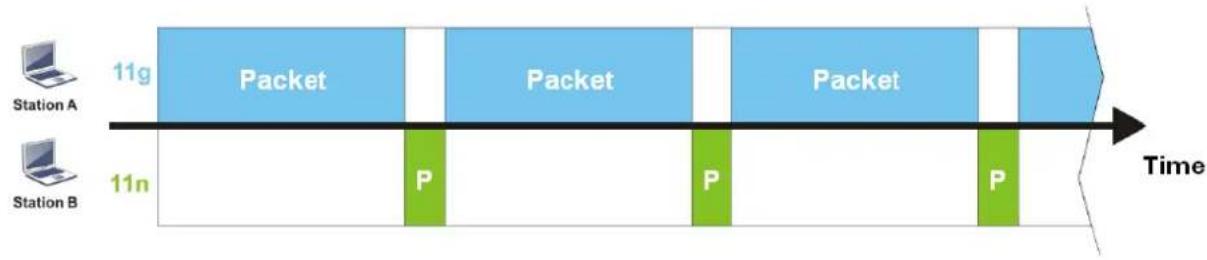
flowchart
graph LR
    A["Station A"] --> B["11g Packet"]
    B --> C["11n P"]
    C --> D["Station B Packet"]
    D --> E["11g Packet"]
    E --> F["11n P"]
    F --> G["Station B Packet"]
    G --> H["11g Packet"]
    style A fill:#f9f,stroke:#333
    style B fill:#bbf,stroke:#333
    style C fill:#bfb,stroke:#333
    style D fill:#bfb,stroke:#333
    style E fill:#fbb,stroke:#333
    style F fill:#fbb,stroke:#333
    style G fill:#fbb,stroke:#333
    style H fill:#fbb,stroke:#333
To improve this problem, Airtime Fairness is added for VigorAP 902. Airtime Fairness function tries to assign similar airtime to each station (A/B) by controlling TX traffic. In the following figure, Station B(11n) has higher probability to send data packets than Station A(11g). By this way, Station B(fast rate) gets fair airtime and it's speed is not limited by Station A(slow rate).
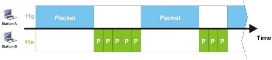
flowchart
graph LR
    A["Station A"] --> B["11g Packet"]
    C["Station B"] --> D["11n P P P P P"]
    B --> E["Time"]
    D --> F["Time"]
    E --> G["Packet"]
    F --> H["Packet"]
It is similar to automatic Bandwidth Limit. The dynamic bandwidth limit of each station depends on instant active station number and airtime assignment. Please note that Airtime Fairness of 2.4GHz and 5GHz are independent. But stations of different SSIDs function together, because they all use the same wireless channel. IN SPECIFIC ENVIRONMENTS, this function can reduce the bad influence of slow wireless devices and improve the overall wireless performance.
Suitable environment:
(1) Many wireless stations.
(2) All stations mainly use download traffic.
(3) The performance bottleneck is wireless connection.
Wireless LAN (2.4GHz) >> Airtime Fairness

text_image
Enable Airtime Fairness Triggering Client Number 2 (2 ~ 64) (Default: 2) OK CancelAvailable settings are explained as follows:
| Item | Description |
| Enable Airtime Fairness | Try to assign similar airtime to each wireless station by controlling TX traffic.Airtime Fairness – Click the link to display the following screen of airtime fairness note.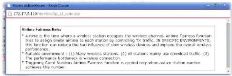 Triggering Client Number –Airtime Fairness function is applied only when active station number achieves this number. Triggering Client Number –Airtime Fairness function is applied only when active station number achieves this number. |
After finishing this web page configuration, please click OK to save the settings.
Note: Airtime Fairness function and Bandwidth Limit function should be mutually exclusive. So their webs have extra actions to ensure these two functions are not enabled simultaneously.
3.5.10 Station Control
Station Control is used to specify the duration for the wireless client to connect and reconnect VigorAP. If such function is not enabled, the wireless client can connect VigorAP until it shuts down.
Such feature is especially useful for free Wi-Fi service. For example, a coffee shop offers free Wi-Fi service for its guests for one hour every day. Then, the connection time can be set as “1 hour” and reconnection time can be set as “1 day”. Thus, the guest can finish his job within one hour and will not occupy the wireless network for a long time.
Note: Up to 300 Wireless Station records are supported by VigorAP.
Wireless LAN (2.4GHz) >> Station Control
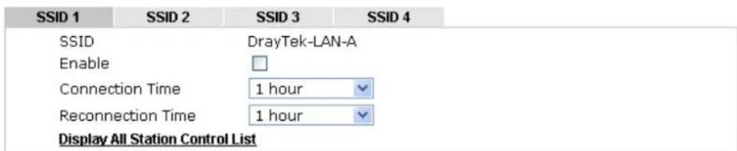
text_image
SSID 1 SSID 2 SSID 3 SSID 4 SSID DrayTek-LAN-A Enable Connection Time 1 hour Reconnection Time 1 hour Display All Station Control ListNote: Once the feature is enabled, the connection time quota will apply to each wireless client (identified by MAC address).

Available settings are explained as follows:
| Item | Description |
| SSID | Display the SSID that the wireless station will use it to connect with Vigor router. |
| Enable | Check the box to enable the station control function. |
| Connection Time / Reconnection Time | Use the drop down list to choose the duration for the wireless client connecting /reconnecting to Vigor router. Or, type the duration manually when you chooseUser defined.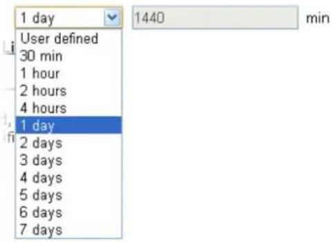 |
| Display All Station Control List | All the wireless stations connecting to Vigor router by using such SSID will be listed on Station Control List. |
After finishing all the settings here, please click OK to save the configuration.
3.5.11 Roaming
The network signal for a single wireless access point might be limited by its coverage range. Therefore, if you want to expand the wireless network in a large exhibition with a quick method, you can install multiple access points with enabling the Roaming feature for each AP to reach the purpose of expanding wireless signals seamlessly.
These access points connecting for each other shall be verified by pre-authentication. This page allows you to enable the roaming feature and the pre-authentication.
Wireless LAN (2.4GHz) >> Roaming
AP-assisted Client Roaming Parameters

text_image
Minimum Basic Rate 1 Mbps Disable RSSI Requirement Strictly Minimum RSSI -73 dBm (42 %) (Default: -73) Minimum RSSI -66 dBm (60 %) (Default: -66) with Adjacent AP RSSI over 5 dBm (Default: 5)Fast Roaming(WPA/802.1x)

text_image
Enable PMK Caching : Cache Period 10 minute(s) (10 ~ 600) (Default: 10) Pre-Authentication
Available settings are explained as follows:
| Item | Description |
| AP-assisted Client Roaming Parameters | When the link rate of wireless station is too low or the signal received by the wireless station is too worse, VigorAP 902 will automatically detect (based on the link rate and RSSI requirement) and cut off the network connection for that wireless station to assist it to connect another Wireless AP to get better signal. Minimum Basic Rate - Check the box to use the drop down list to specify a basic rate (Mbps). When the link rate of the wireless station is below such value, VigorAP 902 will terminate the network connection for that wireless station. Disable RSSI Requirement - If it is selected, VigorAP will not terminate the network connection based on RSSI. Strictly Minimum RSSI - VigorAP uses RSSI (received signal strength indicator) to decide to terminate the network connection of wireless station. When the signal strength is below the value (dBm) set here, VigorAP 902 will terminate the network connection for that wireless station. Minimum RSSI - When the signal strength of the wireless station is below the value (dBm) set here and adjacent AP (must be DrayTek AP and support such feature too) with higher signal strength value (defined in the field of With Adjacent AP RSSI over) is detected by VigorAP 902, VigorAP 902 will terminate the network connection for that wireless station. Later, thewireless station can connect to the adjacent AP (with better RSSI).● With Adjacent AP RSSI over – Specify a value as a threshold. |
| Fast Roaming (WPA/802.1x) | Enable – Check the box to enable fast roaming configuration.PMK Cache Period - Set the expire time of WPA2 PMK (Pairwise master key) cache. PMK Cache manages the list from the BSSIDs in the associated SSID with which it has pre-authenticated. Such feature is available for WPA2/802.1 mode.Pre-Authentication - Enables a station to authenticate to multiple APs for roaming securer and faster. With the pre-authentication procedure defined in IEEE 802.11i specification, the pre-four-way-handshake can reduce handoff delay perceivable by a mobile node. It makes roaming faster and more secure. (Only valid in WPA2)Enable - Enable IEEE 802.1X Pre-Authentication.Disable - Disable IEEE 802.1X Pre-Authentication. |
After finishing this web page configuration, please click OK to save the settings.
3.5.12 Band Steering
Band Steering detects if the wireless clients are capable of 5GHz operation, and steers them to that frequency. It helps to leave 2.4GHz band available for legacy clients, and improves users experience by reducing channel utilization.
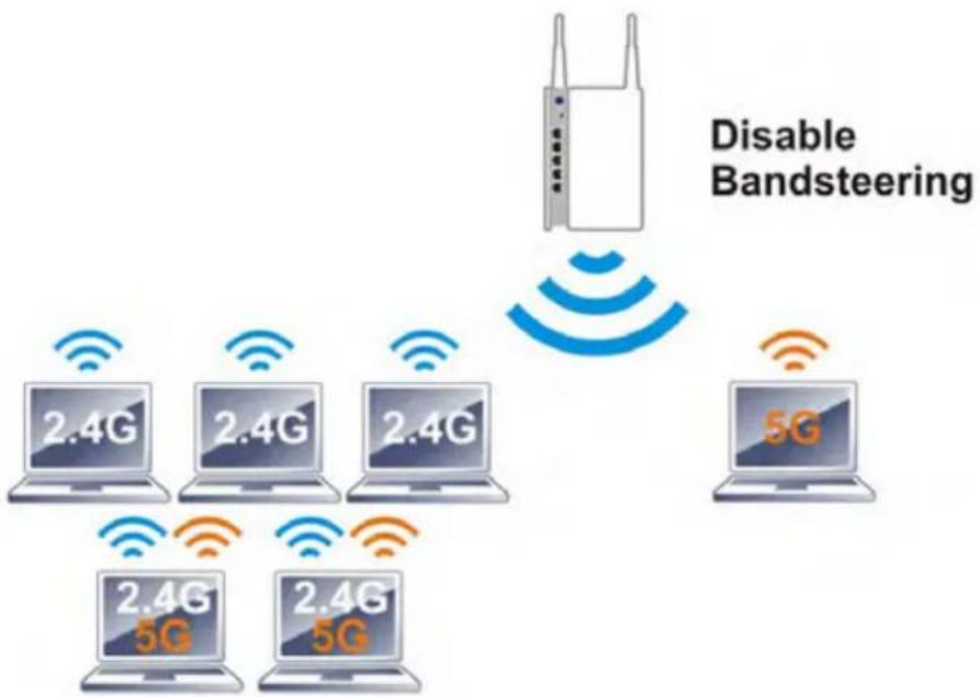
flowchart
graph TD
    A["Disabling Bandsteering"] --> B["Router"]
    B --> C["5G"]
    C --> D["2.4G 5G"]
    C --> E["2.4G 5G"]
    C --> F["2.4G 5G"]
    C --> G["2.4G 5G"]
    style A fill:#f9f,stroke:#333
    style B fill:#ccf,stroke:#333
    style C fill:#cfc,stroke:#333
    style D fill:#fcc,stroke:#333
    style E fill:#cff,stroke:#333
    style F fill:#ffc,stroke:#333
    style G fill:#fcc,stroke:#333
If dual-band is detected, the AP will let the wireless client connect to less congested wireless LAN, such as 5GHz to prevent from network congestion.
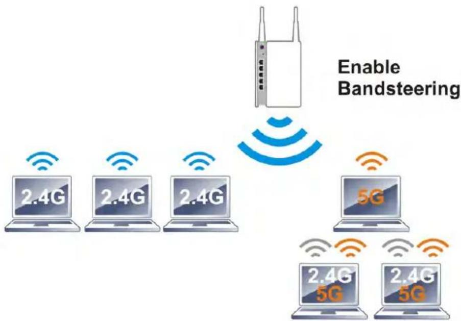
flowchart
graph TD
    A["Router"] -->|Enable Bandsteering| B["2.4G Laptop"]
    A -->|Enable Bandsteering| C["2.4G Laptop"]
    A -->|Enable Bandsteering| D["2.4G Laptop"]
    A -->|Enable Bandsteering| E["5G Laptop"]
    A -->|Enable Bandsteering| F["2.4G 5G Laptop"]
    A -->|Enable Bandsteering| G["2.4G 5G Laptop"]
Note: To make Band Steering work successfully, SS1D and security on 2.4GHz also MUST be broadcasted on 5GHz.
Open Wireless LAN (2.4GHz)>>Band Steering to get the following web page:
Wireless LAN >> Band Steering
Enable Band Steering Check Time for WLAN Client 5G Capability 15 second(s) (1 \~ 60) (Default: 15)
Note: Please setup at least one pair of 2.4GHz and 5GHz Wireless LAN with the same SSID and security.
OK Cancel
Available settings are explained as follows:
| Item | Description |
| Enable Band Steering | If it is enabled, VigorAP will detect if the wireless client is capable of dual-band or not within the time limit.Check Time.... – If the wireless station does not have the capability of 5GHz network connection, the system shall wait and check for several seconds (15 seconds, in default) to make the 2.4GHz network connection. Specify the time limit for VigorAP to detect the wireless client. |
After finishing this web page configuration, please click OK to save the settings.
Below shows how Band Steering works.
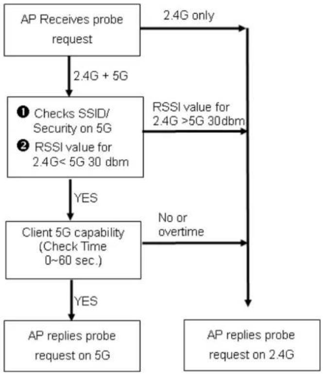
flowchart
graph TD
    A["AP Receives probe request"] -->|2.4G + 5G| B["① Checks SSID/Security on 5G"]
    A -->|2.4G only| C["RSSI value for 2.4G >5G 30 dbm"]
    B -->|YES| D["Client 5G capability (Check Time 0~60 sec.)"]
    B -->|No or overtime| E["AP replies probe request on 2.4G"]
    D -->|YES| F["AP replies probe request on 5G"]
    D -->|No or overtime| E
How to Use Band Steering?
- Open Wireless LAN(2.4GHz)>>Band Steering.
- Check the box of Enable Band Steering and use the default value (15) for check time setting.
Wireless LAN >> Band Steering
Enable Band Steering Check Time for WLAN Client 5G Capability 15 second(s) (1 \~ 60) (Default: 15)
Note: Please setup at least one pair of 2.4GHz and 5GHz Wireless LAN with the same SSID and security.
OK Cancel
- Click OK to save the settings.
- Open Wireless LAN (2.4GHz)>>General Setup and Wireless LAN (5GHz)>>General Setup. Configure SSID as ap902-BandSteering for both pages. Click OK to save the settings.
Wireless LAN (2.4GHz) >> General Setup
General Setting ( IEEE 802.11 )
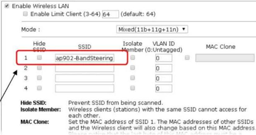
text_image
Enable Wireless LAN Enable Limit Client (3-64) 64 (default: 64) Mode : Mixed(11b+11g+11n) Hide SSID SSID Isolate VLAN ID Member (0:Untagged) MAC Clone 1 ap902-BandSteering 2 3 4 Hide SSID: Prevent SSID from being scanned. Isolate Member: Wireless clients (stations) with the same SSID cannot access for each other. MAC Clone: Set the MAC address of SSID 1. The MAC addresses of other SSIDs and the Wireless client will also change based on this MAC address. Please notice that the last here of this MAC address must be aSame value for 2.4GHz and 5GHz
Wireless LAN (5GHz) >> General Setup
General Setting ( IEEE 802.11 )
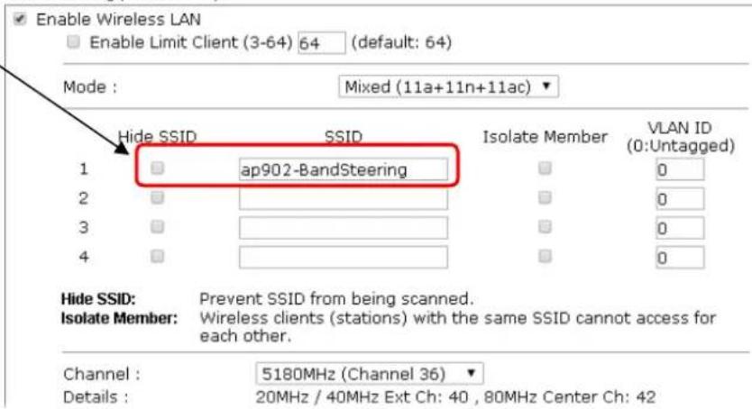
text_image
Enable Wireless LAN Enable Limit Client (3-64) 64 (default: 64) Mode : Mixed (11a+11n+11ac) Hide SSID SSID Isolate Member VLAN ID 1 ap902-BandSteering 0 2 3 4 Hide SSID: Prevent SSID from being scanned. Isolate Member: Wireless clients (stations) with the same SSID cannot access for each other. Channel : 5180MHz (Channel 36) Details : 20MHz / 40MHz Ext Ch: 40 , 80MHz Center Ch: 42- Open Wireless LAN (2.4GHz)>>Security and Wireless LAN (5GHz)>>Security. Configure Security as 12345678 for both pages. Click OK to save the settings.
Wireless LAN (2.4GHz) >> Security Settings
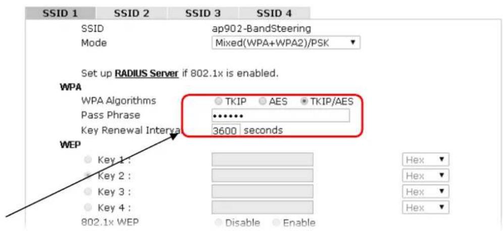
text_image
SSID 1 SSID 2 SSID 3 SSID 4 SSID ap902-BandSteering Mode Mixed(WPA+WPA2)/PSK Set up RADIUS Server if 802.1x is enabled. WPA WPA Algorithms TKIP AES TKIP/AES Pass Phrase •••••• Key Renewal Interval 3600 seconds WEP Key 1: Key 2: Key 3: Key 4: 802.1x WEP Disable Enable Hex Hex Hex HexSame value for 2.4GHz and 5GHz
Wireless LAN (5GHz) >> Security Settings
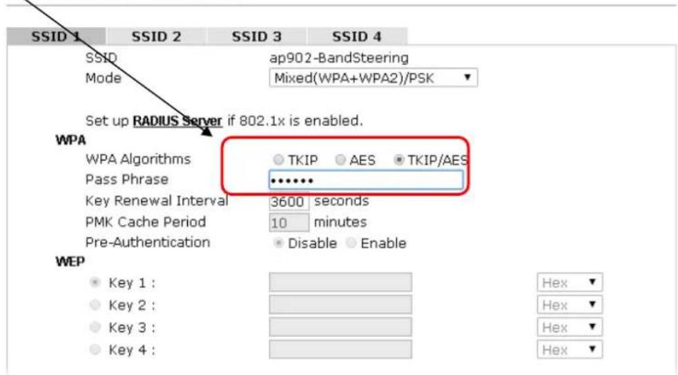
text_image
SSID 1 SSID 2 SSID 3 SSID 4 SSID ap902-BandSteering Mode Mixed(WPA+WPA2)/PSK Set up RADIUS Server if 802.1x is enabled. WPA WPA Algorithms TKIP AES TKIP/AES Pass Phrase ••••••• Key Renewal Interval 3600 seconds PMK Cache Period 10 minutes Pre-Authentication Disable Enable WEP Key 1 : Key 2 : Key 3 : Key 4 : Hex Hex Hex Hex- Now, VigorAP 902 will let the wireless clients connect to less congested wireless LAN, such as 5GHz to prevent from network congestion.
3.5.13 Station List
Station List provides the knowledge of connecting wireless clients now along with its status code.
General
Display general information (e.g., MAC Address, SSID, Auth, Encrypt, TX/RX Rate) for the station.
Wireless LAN (2.4GHz) >> Station List
Station List
| General | Advanced | Control | Neighbor | |||
| Index | MAC Address | Vendor | RSSI | Approx. Distance | SSID | Visit Time |
| 1 | DA:A1:19:E2:65:AD | 5%(-88dBm) | 141.25m | N/A | 0d:0h: | |
| 2 | 00:50:7F:F0:BD:2B | DrayTek | 52%(-69dBm) | 15.85m | N/A | 0d:0h: |
| 3 | 00:50:7F:37:6D:E5 | DrayTek | 47%(-71dBm) | 19.95m | N/A | 0d:0h: |
| 4 | 1C:4B:D6:8B:9C:00 | Azurewav | 18%(-83dBm) | 79.43m | N/A | 0d:1h: |
| 5 | 00:15:AF:A5:24:A0 | Azurewav | 26%(-79dBm) | 50.12m | N/A | 0d:0h: |
| 6 | B0:34:95:22:50:FD | Apple | 47%(-71dBm) | 19.95m | N/A | 0d:0h: |
| 7 | B4:52:7E:D6:68:9D | Sony | 20%(-82dBm) | 70.79m | N/A | 0d:0h: |
| 8 | 00:1F:3C:51:9C:55 | Intel | 39%(-74dBm) | 28.18m | N/A | 0d:1h: |
| Refresh | ||||||
| Add to Access Control :Client's MAC Address : □ : □ : □ : □ : □ : □ | ||||||
Note: 1. Approx. Distance is calculated by actual signal strength of device detected. Inaccuracy might occur based on barrier encountered.
2. Due to the differences in signal strength for different devices, the calculated value of approximate distance also might be different.
3. Trademarks and brand names are the properties of their respective owners.
Add
Available settings are explained as follows:
| Item | Description |
| MAC Address | Display the MAC Address for the connecting client. |
| Hostname | Display the host name of the connecting client. |
| SSID | Display the SSID that the wireless client connects to. |
| Auth | Display the authentication that the wireless client uses for connection with such AP. |
| Encrypt | Display the encryption mode used by the wireless client. |
| Tx Rate/Rx Rate | Display the transmission /receiving rate for packets. |
| Refresh | Click this button to refresh the status of station list. |
| Add to Access Control | Client's MAC Address - For additional security of wireless access, the Access Control facility allows you to restrict the network access right by controlling the wireless LAN MAC address of client. Only the valid MAC address that has been configured can access the wireless LAN interface. |
| Add | Click this button to add current typed MAC address into Access Control. |
Advanced
Display more information (e.g., AID, PSM, WMM, RSSI PhMd, BW, MCS, Rate) for the station.
Control
Display connection and reconnection time of the wireless stations.
Neighbor
Display more information for the neighboring wireless stations.
3.6 Wireless LAN Settings for Station-Infrastructure Mode
When you choose Station-Infrastructure as the operation mode, the Wireless LAN menu items will include General Setup, Site Survey, Statistics and WPS.
text_image
Wireless LAN (2.4GHz) General Setup Site Survey Statistics WPS3.6.1 General Setup
By clicking the General Setup, a new web page will appear so that you could configure the wireless profile and choose proper mode. Please refer to the following figure for more information.
Wireless LAN (2.4GHz) >> General Setup
General Setting ( IEEE 802.11 )
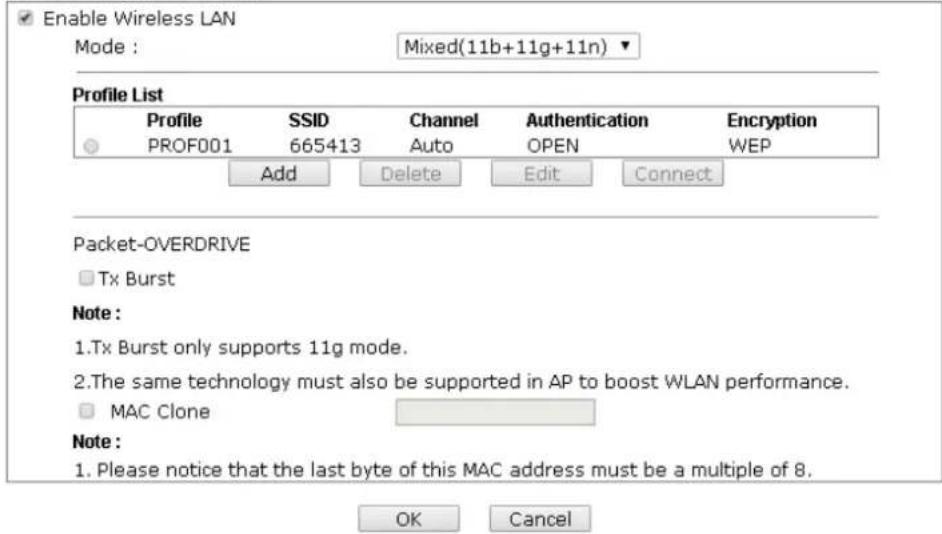
text_image
Enable Wireless LAN Mode : Mixed(11b+11g+11n) Profile List Profile SSID Channel Authentication Encryption PROF001 665413 Auto OPEN WEP Add Delete Edit Connect Packet-OVERDRIVE Tx Burst Note : 1.Tx Burst only supports 11g mode. 2.The same technology must also be supported in AP to boost WLAN performance. MAC Clone Note : 1. Please notice that the last byte of this MAC address must be a multiple of 8. OK CancelAvailable settings are explained as follows:
| Item | Description |
| Enable Wireless LAN | Check the box to enable wireless function. |
| Mode | At present, VigorAP 902 can connect to 11 b only, 11 g only, 11 n only, Mixed (11b+11g), Mixed (11b+11g+11n) and Mixed (11g+11n) stations simultaneously. Simply choose Mixed (11b+11g+11n) mode.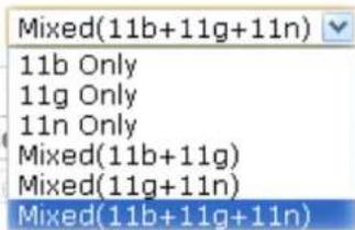 |
| Add | Click this button to add new wireless profiles. |
| Delete | Click this button to delete the selected wireless profile. |
| Edit | Click this button to modify the existing wireless profile. |
| Connect | Click this button to connect the wireless station to AP with the selected profile. |
| Packet-OVERDRIVE | This feature can enhance the performance in data transmission about 40%* more (by checking Tx Burst). It is active only when both sides of Access Point and Station (in wireless client) invoke this function at the same time. That is, the wireless client must support this feature and invoke the function, too.Note:Vigor N61 wireless adapter supports this function. Therefore, you can use and install it into your PC for matching with Packet-OVERDRIVE (refer to the following picture of Vigor N61 wireless utility window, choose Enable for TxBURST on the tab of Option).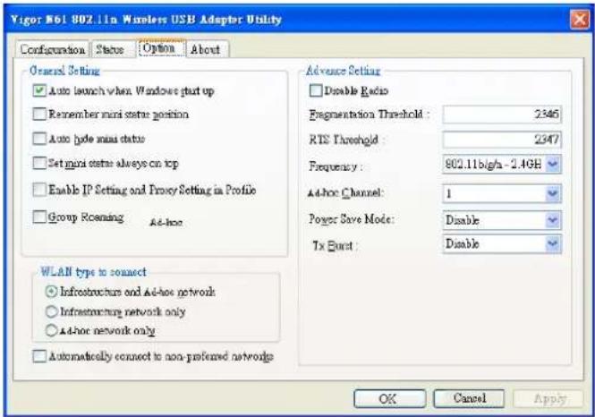 |
| Mac Clone | Check this box and manually enter the MAC address for Station mode driver. |
After finishing this web page configuration, please click OK to save the settings.
Add a New Wireless Profile
To add a new wireless profile for the stations, click Add. The following dialog box will appear.
| System Configuration | |
| Profile Name | PROF001 |
| SSID | |
| Network Type | Infrastructure |
| Power Saving Mode | CAM (Constantly Awake Mode)Power Saving Mode |
| RTS Threshold | Used 2347 |
| Fragment Threshold | Used 2346 |
| Security Policy | |
| Security Mode | OPEN |
| WEP | ||
| WEP Key Length | 64 bit (10 hex digits / 5 ascii keys) | |
| WEP Key Entry Method | Hexadecimal | |
| WEP Keys | WEP Key 1 : | |
| WEP Key 2 : | ||
| WEP Key 3 : | ||
| WEP Key 4 : | ||
| Default Key | Key 1 | |
Available settings are explained as follows:
| Item | Description |
| Profile Name | Type a name for the new profile. |
| SSID | Type the name for such access point that can be used for connection by the stations. |
| Network Type | Infrastructure- In this mode, you can connect the access point to Ethernet device such as TV and Game player to enable the Ethernet device as a wireless station and join to a wireless network through an access point or AP router.802.11 Ad Hoc-An ad-hoc network is a network where wireless stations can communicate with peer to peer (P2P).Infrastructure802.11 Ad HocInfrastructure |
| Power Saving Mode | Choose the power saving mode for such device.CAM- Choose this item if it is not necessary to performpower saving job.Power Saving Mode – Choose this item to get into the power saving status when there is no data passing through the access point. |
| RTS Threshold | Set the RTS threshold of wireless radio. Do not modify default value if you don’t know what it is, default value is 2347. |
| Fragment Threshold | Set the Fragment threshold of wireless radio. Do not modify default value if you don’t know what it is, default value is 2346. |
| Security Mode | 802.11 standard defines two mechanisms for authentication of wireless LAN clients: Open Authentication and Shared Key Authentication.Choose one of the security modes from the drop down list. If you choose OPEN or SHARED, you have to type WEP information.OPEN – Open authentication is basically null authentication algorithm, which means that there is no verification of the user.SHARED – It works similar to Open authentication with only one major difference. If you choose OPEN with WEP encryption key, the WEP keys is used to encrypt and decrypt the data but not for authentication. In Shared key authentication, WEP encryption will be used for authentication.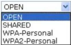 If you choose WPA-Personal or WPA2-Personal, the corresponding WPA settings will be listed as follows. You have to choose the WPA algorithms and type the pass phrase for such security mode. If you choose WPA-Personal or WPA2-Personal, the corresponding WPA settings will be listed as follows. You have to choose the WPA algorithms and type the pass phrase for such security mode.  WPA Algorithms – Choose Temporal Key Integrity Protocol (TKIP) or AES for data encryption.Pass Phrase – Please type 8 to 63 alphanumerical characters here. WPA Algorithms – Choose Temporal Key Integrity Protocol (TKIP) or AES for data encryption.Pass Phrase – Please type 8 to 63 alphanumerical characters here. |
WEP
WEP Key Length - WEP (Wired Equivalent Privacy) is a common encryption mode. It is safe enough for home and personal use. However, if you need higher level of security, please consider using WPA encryption (see next section).
Some wireless clients do not support WPA, but support WEP. Therefore WEP is still a good choice for you if you have such kind of client in your network environment.
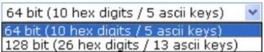
text_image
64 bit (10 hex digits / 5 ascii keys) 64 bit (10 hex digits / 5 ascii keys) 128 bit (26 hex digits / 13 ascii keys)WEP Key Entry Method - There are two types of WEP key length: 64-bit and 128-bit. Using 128-bit is safer than 64-bit, but it will reduce some data transfer performance.
There are two types of key method: ASCII and Hex. When you select a key format, the number of characters of key will be displayed. For example, if you select 64-bit as key length, and Hex as key format, you'll see the message at the right of Key Format is 'Hex (10 characters) which means the length of WEP key is 10 characters.
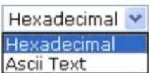
WEP Keys (Key 1 – Key 4) - Four keys can be entered here, but only one key can be selected at a time. The format of WEP Key is restricted to 5 ASCII characters or 10 hexadecimal values in 64-bit encryption level, or restricted to 13 ASCII characters or 26 hexadecimal values in 128-bit encryption level. The allowed content is the ASCII characters from 33(!) to 126(\~) except '#' and ''. Such feature is available for WEP mode.
Default Key – Choose one of the key settings.
Below shows an example for a wireless profile created.
Wireless LAN (2.4GHz) >> General Setup
General Setting ( IEEE 802.11 )
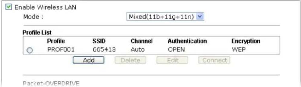
text_image
Enable Wireless LAN Mode : Mixed(11b+11g+11n) Profile List Profile SSID Channel Authentication Encryption PROF001 665413 Auto OPEN WEP Add Delete Edit Connect Packet-OVERDRIVE3.6.2 Site Survey
The page will list the access points nearby as VigorAP 902 is set to Station mode. You can select one of the access points to associate.
Wireless LAN (2.4GHz) >> Station Site Survey
Site Survey
| SSID | BSSID | RSSI | Channel | Encryption | Authentication |
| Scan | Connect | Add Profile |
Available settings are explained as follows:
| Item | Description |
| SSID | Display the SSID name of the access point. |
| BSSID | Display the BSSID (MAC Address) of the access point. |
| RSSI | Display the signal strength of the access point. RSSI is the abbreviation of Receive Signal Strength Indication. |
| Channel | Display the channel number of the access point. |
| Encryption | Display the encryption setting of the access points. If you have selected the access point with security setting, you have to go to 2-7 Wireless Security to set the same security with the access point you want to associate. |
| Authentication | Display the authentication type of the access point. |
| Scan | Search the stations connected to such access point. |
| Connect | Connect to the wireless AP that you choose. |
| Add Profile | The system will add a profile automatically for you to connect with the wireless AP that you choose. |
Wireless LAN >> Station Site Survey
Site Survey
| SSID | BSSID | RSSI | Channel | Encryption | Authentication |
| staffs_5F | 00-1D-AA-C5-59-40 | 81% | 1 | TKIP/AES | Mixed(WPA+WPA2)/PSK |
| staffs | 02-1D-AA-C5-59-40 | 86% | 1 | TKIP/AES | Mixed(WPA+WPA2)/PSK |
| guest_5F | 06-1D-AA-C5-59-40 | 81% | 1 | TKIP/AES | Mixed(WPA+WPA2)/PSK |
| staffs_4F | 0A-1D-AA-C5-59-40 | 86% | 1 | TKIP/AES | Mixed(WPA+WPA2)/PSK |
| staffs_6F | 00-1D-AA-7F-4D-24 | 50% | 8 | TKIP/AES | Mixed(WPA+WPA2)/PSK |
| staffs | 02-1D-AA-78-4D-24 | 55% | 8 | TKIP/AES | Mixed(WPA+WPA2)/PSK |
| v2860 PQC ... | 02-1D-AA-86-BA-D0 | 20% | 11 | AES | WPA2/PSK |
| v2925 pqc ... | 00-1D-AA-7F-5D-8C | 29% | 11 | TKIP/AES | Mixed(WPA+WPA2)/PSK |
| DrayTek | 00-1D-AA-7F-5D-58 | 44% | 11 | TKIP/AES | Mixed(WPA+WPA2)/PSK |
| 00-1D-AA-86-1B-B8 | 91% | 11 | WEP | ||
| RD2_Guest0... | 00-1D-AA-E6-0D-82 | 39% | 10 | NONE | |
| mars | 00-1D-AA-E4-86-D8 | 24% | 11 | TKIP/AES | Mixed(WPA+WPA2)/PSK |
| TEST_001 | 00-50-7F-52-2F-58 | 24% | 11 | TKIP/AES | Mixed(WPA+WPA2)/PSK |
| DrayTek-LA... | 00-1D-AA-9D-1F-B8 | 24% | 11 | TKIP/AES | Mixed(WPA+WPA2)/PSK |
3.6.3 Statistics
This page displays the statistics for data transmission and receiving between the access point and the stations.
Wireless LAN >> Station Statistics
Transmit Statistics
| Frames Transmitted Successfully | 2407 |
| Frames Transmitted Successfully Without Retry | 2407 |
| Frames Transmitted Successfully After Retry(s) | 0 |
| Frames Fail To Receive ACK After All Retries | 0 |
| RTS Frames Successfully Receive CTS | 0 |
| RTS Frames Fail To Receive CTS | 0 |
Receive Statistics
| Frames Received Successfully | 18249 |
| Frames Received With CRC Error | 71873 |
| Frames Dropped Due To Out-of-Resource | 0 |
| Duplicate Frames Received | 19 |
Reset Counters
Click Rest Counters if required.
3.6.4 WPS (Wi-Fi Protected Setup)
Wi-Fi Protected Setup (WPS) is the simplest way to build connection between wireless network clients and the access point. You don't have to select encryption mode and input a long encryption passphrase every time when you need to setup a wireless client. You only have to press a button on wireless client and the access point, and the WPS will do the setup for you.
VigorAP 902 supports two types of WPS: Push-Button Configuration (PBC), and PIN code. If you want to use PBC, you have to switch VigorAP 902 to WPS mode and push a specific button on the wireless client to start WPS mode. You can push Reset/WPS button of this VigorAP 902, or click PBC Start button in the web configuration interface to do this; if you want to use PIN code, you have to provide the PIN code of the wireless client you wish to connect to this access point and then switch the wireless client to WPS mode.
Note: WPS function of VigorAP 902 will not work for those wireless AP/clients do not support WPS.
To use WPS function to set encrypted connection between VigorAP 902 and WPS-enabled wireless AP, please open Wireless LAN >>WPS. The following information will be displayed:
WPS AP site survey
| No. | SSID | BSSID | RSSI ch. | Auth | Encrypt | ver. | Status |
| ● | staffs_5F | 001DAAABDE608 | 76% 1 | Mixed(WPA+WPA2)/PSK TKIP/AES | 1.0 | Unconf. | |
| ● | mars | 001DAAE4B6D8 | 29% 13 | Mixed(WPA+WPA2)/PSK TKIP/AES | 1.0 | Unconf. | |
| ● | RD2_Test_Johnny00 | 001DAAE1D458 | 44% 8 | Mixed(WPA+WPA2)/PSK TKIP/AES | 1.0 | Conf. | |
| ● | 2862_kyeh_test | 001DAAEA38A0 | 24% 9 | Mixed(WPA+WPA2)/PSK TKIP/AES | 1.0 | Conf. | |
| ● | RD0_Robin | 001DAADFCFF0 | 39% 11 | Mixed(WPA+WPA2)/PSK TKIP/AES | 1.0 | Unconf. | |
| ● | BBB8B | 001DAAE60E50 | 0% 3 | undefined | undefined | ? | ? |
| ● | WEP | 16 | 2% | UUID:0000100000000000000001daao60e50 RF Band:2.4G/5G | ? | ? | |
| ● | 2800 kaylee 2.4G | 001DAAB0BC90 | 15% 9 | Mixed(WPA+WPA2)/PSK TKIP/AES | 1.0 | Unconf. | |
| ● | v2133_D1 | 001DAAEEC1C0 | 0% 6 | Mixed(WPA+WPA2)/PSK TKIP/AES | 1.0 | Conf. | |
| ● | v2820 PQC ting | 00507FEDE2D8 | 0% 6 | WPA/PSK | TKIP | 1.0 | Unconf. |
| ● | Jackson_2133 | 001DAAEFC1A8 | 5% 6 | OPEN | NONE | 1.0 | Conf. |
Refresh
Device Configure
| Configure via Push Button | Start PBC | |
| Configure via Client PinCode | Start PIN Renew PIN | |
| Cancel |
Status: Idle
Available settings are explained as follows:
| Item | Description |
| SSID | Display the SSID name of the access point. |
| BSSID | Display the BSSID (MAC Address) of the access point. |
| RSSI | Display the signal strength of the access point. RSSI is the abbreviation of Receive Signal Strength Indication. |
| Ch. (Channel) | Display the channel number of the access point. |
| Auth. (Authentication) | Display the authentication type of the access point. |
| Encrypt (Encryption) | Display the encryption setting of the access points. If you have selected the access point with security setting, you have to go to 2-7 Wireless Security to set the same security with the access point you want to associate. |
| Ver. (Version) | Display the version of WPS. |
| Status | Display the status of WPS access point. |
| Refresh | Click this button to refresh the AP site survey. |
| Start PBC | Click Start PBC to make a WPS connection within 2 minutes. |
| Start PIN | When using PinCode method, it is required to enter PIN Code (Personal Identification Number Code, 8-digit numbers) into Registrar. When the wireless station is Enrollee, the users can use Renew PIN to re-generate a new PIN code. |
| Renew PIN | Click this button to re-generate a new PIN code. |
Note: When you're using PBC type WPS setup, you must press PBC button (hardware or software) of wireless client within 2 minutes. If you didn't press PBC button of wireless client within this time period, please press PBC button (hardware or software) of this access point again.
3.7 Wireless LAN Settings for AP Bridge-Point to Point/AP Bridge-Point to Multi-Point Mode
When you choose AP Bridge-Point to Point or Point-to Multi-Point Mode as the operation mode, the Wireless LAN menu items will include General Setup, Advanced Setting, AP Discovery, and WDS AP Status.
Wireless LAN (2.4GHz)
General Setup
Advanced Setting
AP Discovery
WDS AP Status
AP Bridge-Point to Point allows VigorAP 902 to connect to another VigorAP 902 which uses the same mode. All wired Ethernet clients of both VigorAP 902s will be connected together.
Point-to Multi-Point Mode allows AP 902 to connect up to four AP 902s which uses the same mode. All wired Ethernet clients of every VigorAP 902 will be connected together.
3.7.1 General Setup
By clicking the General Setup, a new web page will appear so that you could configure security, Tx Burst and choose proper mode. Please refer to the following figure for more information.
Wireless LAN (2.4GHz) >> General Setup
General Setting ( IEEE 802.11 )
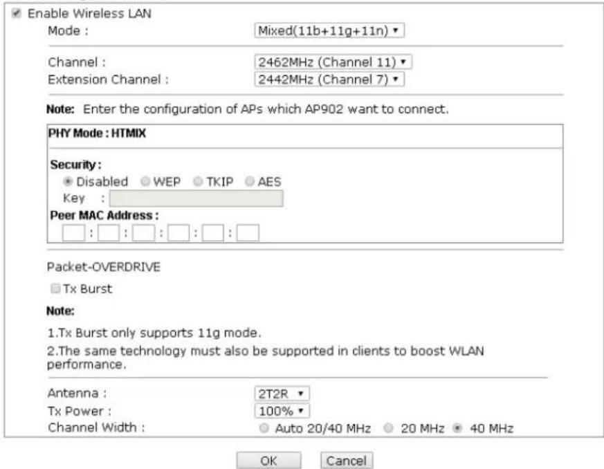
text_image
Enable Wireless LAN Mode : Mixed(11b+11g+11n) Channel : 2462MHz (Channel 11) Extension Channel : 2442MHz (Channel 7) Note: Enter the configuration of APs which AP902 want to connect. PHY Mode : HTMIX Security: ● Disabled ● WEP ● TKIP ● AES Key : Peer MAC Address : □ : □ : □ : □ : □ : □ Packet-OVERDRIVE □ Tx Burst Note: 1.Tx Burst only supports 11g mode. 2.The same technology must also be supported in clients to boost WLAN performance. Antenna : 2T2R Tx Power : 100% Channel Width : Auto 20/40 MHz 20 MHz 40 MHz OK CancelAvailable settings are explained as follows:
| Item | Description |
| Enable Wireless LAN | Check the box to enable wireless function. |
| Mode | At present, VigorAP 902 can connect to 11b only, 11g only, 11n only, Mixed (11b+11g), Mixed (11g+11n) and Mixed (11b+11g+11n) stations simultaneously. Simply choose Mixed (11b+11g+11n) mode.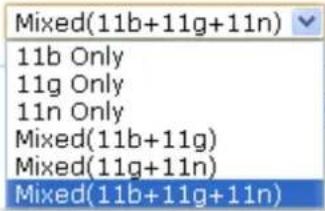 |
| Channel | Means the channel of frequency of the wireless LAN. The default channel is 11. You may switch channel if the selected channel is under serious interference. If you have no idea of choosing the frequency, please selectAutoSelectto let system determine for you. |
| Extension Channel | With 802.11n, there is one option to double the bandwidth per channel. The available extension channel options will be varied according to theChannelselected above. |
| Rate | If you choose 11g Only, 11b Only or 11n Only, such feature will be available for you to set data transmission rate. |
| PHY Mode | Data will be transmitted via HTMIX mode.Each access point should be setup to the samePHY Modefor connecting with each other. |
| Security | Select WEP, TKIP or AES as the encryption algorithm. Type the key number if required. |
| Peer MAC Address | Type the peer MAC address for the access point that VigorAP 902 connects to. |
| Packet-OVERDRIVE | This feature can enhance the performance in data transmission about 40%* more (by checkingTx Burst). It is active only when both sides of Access Point and Station (in wireless client) invoke this function at the same time. That is, the wireless client must support this feature and invoke the function, too.Note:Vigor N61 wireless adapter supports this function. Therefore, you can use and install it into your PC for matching with Packet-OVERDRIVE (refer to the following picture of Vigor N61 wireless utility window, chooseEnable forTxBURSTon the tab ofOption).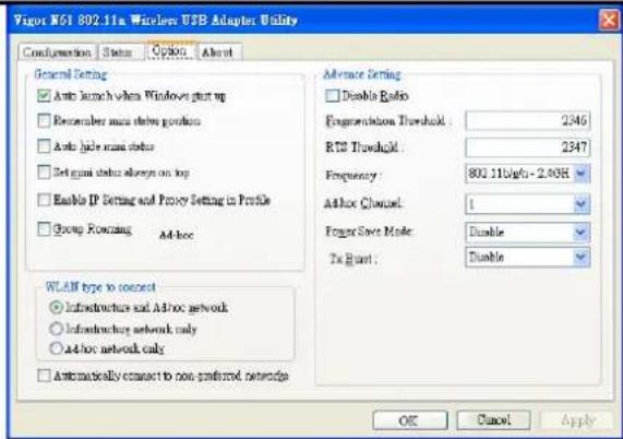 |
| Antenna | VigorAP 902 can be attached with two antennas to have good data transmission via wireless connection. However, if you have only one antenna attached, please choose 1T1R.[IMAGE] |
| Tx Power | The default setting is the maximum (100%). Lowering down the value may degrade range and throughput of wireless.[IMAGE] |
| Channel Width | Auto 20/40 MHZ- the device will use 20Mhz or 40Mhz for data transmission and receiving according to the station capability. Such channel can increase the performance for data transmission.20 MHZ- the device will use 20Mhz for data transmission and receiving between the AP and the stations.40 MHZ- the device will use 40Mhz for data transmission and receiving between the AP and the stations. |
After finishing this web page configuration, please click OK to save the settings.
3.7.2 Advanced Setting
This page is to determine which algorithm will be selected for wireless transmission rate.
Wireless LAN (2.4GHz) >> Advanced Setting

text_image
Rate Adaptation Algorithm Fragment Length (256 - 2346) RTS Threshold (1 - 2347) Country Code New Old 2346 bytes 2347 bytes (Reference)
Available settings are explained as follows:
| Item | Description |
| Rate Adaptation Algorithm | Wireless transmission rate is adapted dynamically. Usually, performance of “new” algorithm is better than “old”. |
| Fragment Length | Set the Fragment threshold of wireless radio. Do not modify default value if you don’t know what it is, default value is 2346. |
| RTS Threshold | Minimize the collision (unit is bytes) between hidden stations to improve wireless performance.Set the RTS threshold of wireless radio. Do not modify default value if you don’t know what it is, default value is 2347. |
| Country Code | VigorAP broadcasts country codes by following the 802.11d standard. However, some wireless stations will detect / scan the country code to prevent conflict occurred. If conflict is detected, wireless station will be warned and is unable to make network connection. Therefore, changing the country code to ensure successful network connection will be necessary for some clients. |
3.7.3 AP Discovery
VigorAP 902 can scan all regulatory channels and find working APs in the neighborhood. Based on the scanning result, users will know which channel is clean for usage. Also, it can be used to facilitate finding an AP for a WDS link. Notice that during the scanning process (about 5 seconds), no client is allowed to connect to VigorAP 902.
This page is used to scan the existence of the APs on the wireless LAN. Yet, only the AP which is in the same channel of VigorAP 902 can be found. Please click Scan to discover all the connected APs.
Wireless LAN (2.4GHz) >> Access Point Discovery
Access Point List
| Select SSID | BSSID | RSSI | Channel | Encryption | Authentication |
| Scan |
See Channel Statistics
Note: During the scanning process (about 5 seconds), no station is allowed to connect with the AP.
| AP's MAC Address | □ : □ : □ : □ : □ | AP's SSID |
| Add to WDS Settings: | Add |
Available settings are explained as follows:
| Item | Description |
| SSID | Display the SSID of the AP scanned by VigorAP 902. |
| BSSID | Display the MAC address of the AP scanned by VigorAP 902. |
| RSSI | Display the signal strength of the access point. RSSI is the abbreviation of Received Signal Strength Indication. |
| Channel | Display the wireless channel used for the AP that is scanned by VigorAP 902. |
| Encryption | Display the encryption mode for the scanned AP. |
| Authentication | Display the authentication type that the scanned AP applied. |
| Scan | It is used to discover all the connected AP. The results will be shown on the box above this button |
| Channel Statistics | It displays the statistics for the channels used by APs. |
| AP's MAC Address | If you want the found AP applying the WDS settings, please type in the AP's MAC address. |
| AP's SSID | To specify an AP to be applied with WDS settings, you can specify MAC address or SSID for the AP. Here is the place that you can type the SSID of the AP. |
| Add | Type the MAC address of the AP. Click Add. Later, the MAC address of the AP will be added and be shown on WDS settings page. |
3.7.4 WDS AP Status
VigorAP 902 can display the status such as MAC address, physical mode, power save and bandwidth for the working AP connected with WDS. Click Refresh to get the newest information.
Wireless LAN (2.4GHz) >> WDS AP Status
WDS AP List
| AID | MAC Address | 802.11 Physical Mode | Power Save | Bandwidth |
Refresh
3.8 Wireless LAN Settings for AP Bridge-WDS Mode
When you choose AP Bridge-WDS as the operation mode, the Wireless LAN menu items will include General Setup, Security, Access Control, WPS, Advanced Setting, AP Discovery, WDS AP Status, WMM Configuration, Bandwidth Management, Airtime Fairness, Station Control, Roaming, Band Steering and Station List.
Wireless LAN (2.4GHz)
General Setup
Security
Access Control
WPS
Advanced Setting
AP Discovery
WDS AP Status
WMM Configuration
Bandwidth Management
Airtime Fairness
Station Control
Roaming
Band Steering
Station List
3.8.1 General Setup
By clicking the General Setup, a new web page will appear so that you could configure security, Tx Burst and choose proper mode. Please refer to the following figure for more information.
General Setting ( IEEE 802.11 )
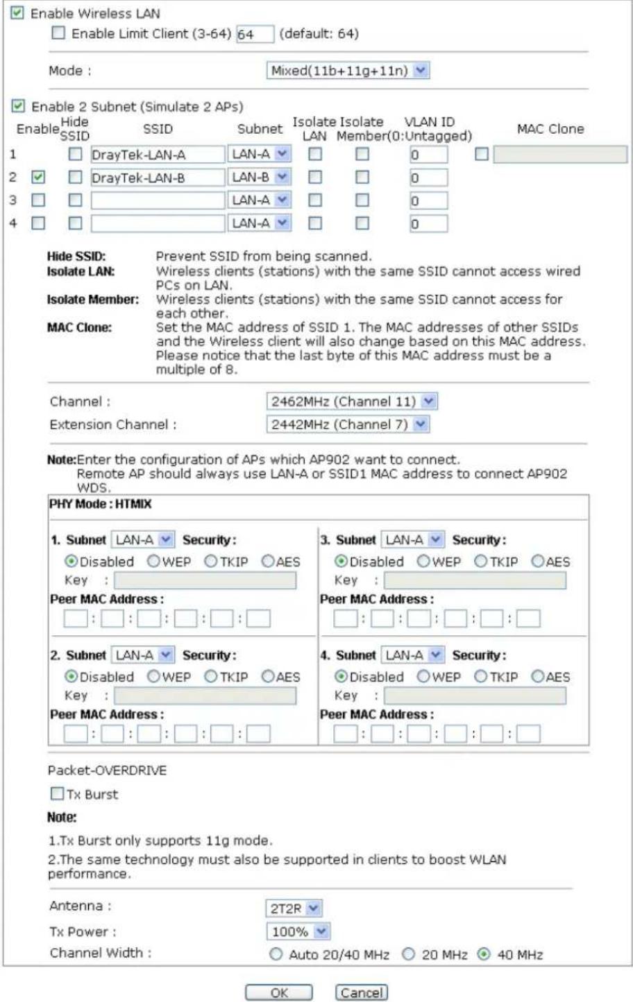
Available settings are explained as follows:
| Item | Description |
| Enable Wireless LAN | Check the box to enable wireless function. |
| Enable Limit Client | Check the box to set the maximum number of wireless stations which try to connect Internet through VigorAP. The numberyou can set is from 3 to 64. |
| Mode | At present, VigorAP 902 can connect to 11b only, 11g only, 11n only, Mixed (11b+11g), Mixed (11g+11n) and Mixed (11b+11g+11n) stations simultaneously. Simply choose Mixed (11b+11g+11n) mode.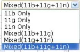 |
| Enable 2 Subnet(Simulate 2 APs) | Check the box to enable the function for two independent subnets. Once you enable this function, LAN-A and LAN-B would be independent. Next, you can connect one router in LAN-A, and another router in LAN-B. Such mechanism can make you feeling that you have two independent AP/subnet functions in one VigorAP 902.If you disable this function, LAN-A and LAN-B ports are in the same domain. You could only connect one router (no matter connecting to LAN-A or LAN-B) in this environment. |
| Hide SSID | Check it to prevent from wireless sniffing and make it harder for unauthorized clients or STAs to join your wireless LAN. Depending on the wireless utility, the user may only see the information except SSID or just cannot see any thing about VigorAP 902 while site surveying. The system allows you to set four sets of SSID for different usage. |
| SSID | Set a name for VigorAP 902 to be identified. Default settings are DrayTek-LAN-A and DrayTek-LAN-B. When Enable 2 Subnet is enabled, you can specify subnet interface (LAN-A or LAN-B) for each SSID by using the drop down menu. |
| Subnet | Choose LAN-A or LAN-B for each SSID. If you choose LAN-A, the wireless clients connecting to this SSID could only communicate with LAN-A. |
| Isolate LAN | Check this box to make the wireless clients (stations) with the same SSID not accessing for wired PC in LAN. |
| Isolate Member | Check this box to make the wireless clients (stations) with the same SSID not accessing for each other. |
| VLAN ID | Type the value for such SSID. Packets transferred from such SSID to LAN will be tagged with the number.If your network uses VLANs, you can assign the SSID to a VLAN on your network. Client devices that associate using the SSID are grouped into this VLAN. The VLAN ID range is from 3 to 4095. The VLAN ID is 0 by default, it means disabling the VLAN function for the SSID. |
| MAC Clone | Check this box and manually enter the MAC address of the device with SSID 1. The MAC address of other SSIDs willchange based on this MAC address. |
| Channel | Means the channel of frequency of the wireless LAN. You may switch channel if the selected channel is under serious interference. If you have no idea of choosing the frequency, please selectAutoSelectto let system determine for you. |
| Extension Channel | With 802.11n, there is one option to double the bandwidth per channel. The available extension channel options will be varied according to theChannelselected above. Configure the extension channel you want. |
| Rate | If you choose 11g Only, 11b Only or 11n Only, such feature will be available for you to set data transmission rate. |
| PHY Mode | Data will be transmitted via HTMIX mode.Each access point should be setup to the samePHY Modefor connecting with each other. |
| Subnet | Choose LAN-A or LAN-B for each SSID. |
| Security | Select Disabled, WEP, TKIP or AES as the encryption algorithm. |
| Peer MAC Address | Four peer MAC addresses are allowed to be entered in this page at one time. |
| Packet-OVERDRIVE | This feature can enhance the performance in data transmission about 40%* more (by checkingTx Burst). It is active only when both sides of Access Point and Station (in wireless client) invoke this function at the same time. That is, the wireless client must support this feature and invoke the function, too.Note:Vigor N61 wireless adapter supports this function. Therefore, you can use and install it into your PC for matching with Packet-OVERDRIVE (refer to the following picture of Vigor N61 wireless utility window, chooseEnablefor TxBURSTon the tab ofOption). |
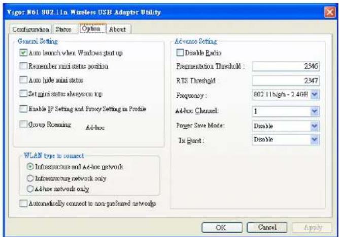
text_image
Vigor N61 802.11n Wireless USB Adapter Utility Configuration State Option About General Setting ✓ Auto launch when Windows start up ☐ Remember mini status position ☐ Auto hide mini status ☐ Set mini status always on top ☐ Enable IP Setting and Proxy Setting in Profile ☐ Group Recensing Ad-hoc Advance Setting ☐ Disable Radio Representation Threshold: 2346 RTS Threshold 2347 Frequency: 802.11b/g/-2.4GB Ad-hoc Channel: 1 Power Save Mode: Disable In Burst: Disable WLAN type to connect ○ Infrastructure and Ad-hoc network ○ Infrastructure network only ○ Ad-hoc network only ☐ Automatically connect to non-preferred networks OK Cancel Apply| Antenna | VigorAP 902 can be attached with two antennas to have good data transmission via wireless connection. However, if you have only one antenna attached, please choose 1T1R. |
| Tx Power | The default setting is the maximum (100%). Lowering down the value may degrade range and throughput of wireless.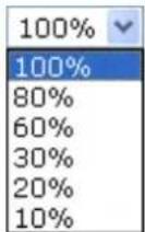 |
| Channel Width | Auto 20/40 MHZ- the device will use 20Mhz or 40Mhz for data transmission and receiving according to the station capability. Such channel can increase the performance for data transmission.20 MHZ- the device will use 20Mhz for data transmission and receiving between the AP and the stations.40 MHZ- the device will use 40Mhz for data transmission and receiving between the AP and the stations. |
After finishing this web page configuration, please click OK to save the settings.
3.8.2 Security
This page allows you to set security with different modes for SSID 1, 2, 3 and 4 respectively. After configuring the correct settings, please click OK to save and invoke it.
By clicking the Security Settings, a new web page will appear so that you could configure the settings.
Wireless LAN (2.4GHz) >> Security Settings
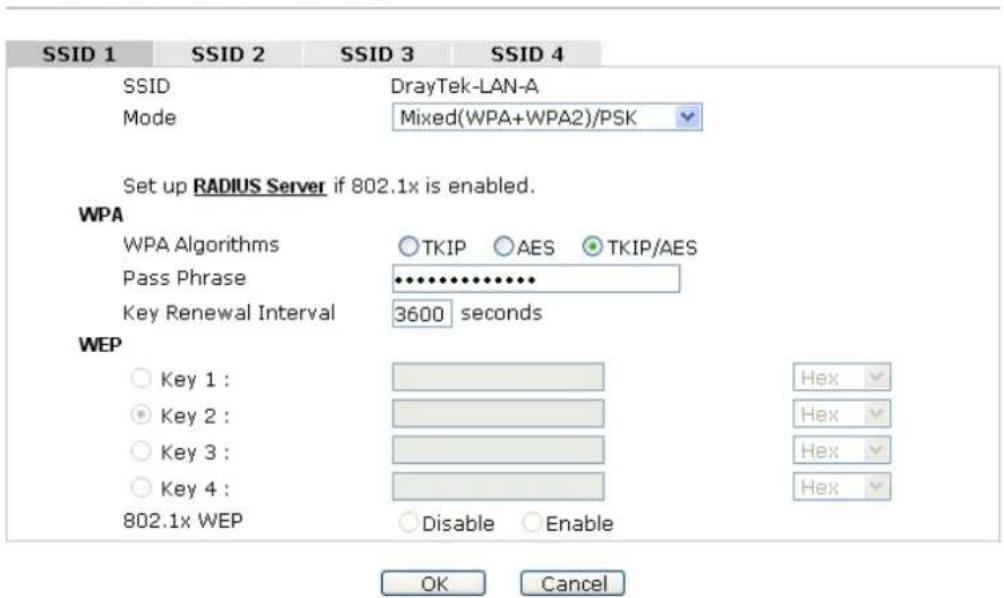
text_image
SSID 1 SSID 2 SSID 3 SSID 4 SSID DrayTek-LAN-A Mode Mixed(WPA+WPA2)/PSK Set up RADIUS Server if 802.1x is enabled. WPA WPA Algorithms ○ TKIP ○ AES ○ TKIP/AES Pass Phrase ••••••••••• Key Renewal Interval 3600 seconds WEP ○ Key 1 : ● Key 2 : ○ Key 3 : ○ Key 4 : 802.1x WEP ○ Disable ○ Enable Hex Hex Hex Hex OK CancelAvailable settings are explained as follows:
| Item | Description |
| Mode | There are several modes provided for you to choose. |
| Disable | |
| Disable | |
| WEP | |
| WPA/PSK | |
| WPA2/PSK | |
| Mixed(WPA+WPA2)/PSK | |
| WEP/802.1x | |
| WPA/802.1x | |
| WPA2/802.1x | |
| Mixed(WPA+WPA2)/802.1x | |
| Disable - The encryption mechanism is turned off. | |
| WEP - Accepts only WEP clients and the encryption key should be entered in WEP Key. | |
| WPA/PSK or WPA2/PSK or Mixed (WPA+WPA2)/PSK - Accepts only WPA clients and the encryption key should be entered in PSK. The WPA encrypts each frame transmitted from the radio using the key, which either PSK (Pre-Shared Key) entered manually in this field below or automatically negotiated via 802.1x authentication. | |
| WEP/802.1x - The built-in RADIUS client feature enables VigorAP 902 to assist the remote dial-in user or a wireless station and the RADIUS server in performing mutual authentication. It enables centralized remote access | |
| authentication for network management.The WPA encrypts each frame transmitted from the radio using the key, which either PSK (Pre-Shared Key) entered manually in this field below or automatically negotiated via 802.1x authentication. Select WPA, WPA2 or Auto as WPA mode.WPA/802.1x - The WPA encrypts each frame transmitted from the radio using the key, which either PSK (Pre-Shared Key) entered manually in this field below or automatically negotiated via 802.1x authentication.WPA2/802.1x - The WPA encrypts each frame transmitted from the radio using the key, which either PSK (Pre-Shared Key) entered manually in this field below or automatically negotiated via 802.1x authentication. | |
| WPA Algorithms | Select TKIP, AES or TKIP/AES as the algorithm for WPA. Such feature is available for WPA2/802.1x, WPA/802.1x, WPA/PSK or WPA2/PSK or Mixed (WPA+WPA2)/PSK mode. |
| Pass Phrase | Either 8~63 ASCII characters, such as 012345678..(or 64 Hexadecimal digits leading by 0x, such as "0x321253abcde..."). Such feature is available for WPA/PSK or WPA2/PSK or Mixed (WPA+WPA2)/PSK mode. |
| Key Renewal Interval | WPA uses shared key for authentication to the network. However, normal network operations use a different encryption key that is randomly generated. This randomly generated key that is periodically replaced. Enter the renewal security time (seconds) in the column. Smaller interval leads to greater security but lower performance. Default is 3600 seconds. Set 0 to disable re-key. Such feature is available for WPA2/802.1,WPA/802.1x, WPA/PSK or WPA2/PSK or Mixed (WPA+WPA2)/PSK mode. |
| Key 1 - Key 4 | Four keys can be entered here, but only one key can be selected at a time. The format of WEP Key is restricted to 5 ASCII characters or 10 hexadecimal values in 64-bit encryption level, or restricted to 13 ASCII characters or 26 hexadecimal values in 128-bit encryption level. The allowed content is the ASCII characters from 33(!) to 126(~) except '#' and ';'. Such feature is available for WEP mode.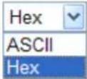 |
| 802.1x WEP | Disable - Disable the WEP Encryption. Data sent to the AP will not be encrypted.Enable - Enable the WEP Encryption.Such feature is available for WEP/802.1x mode. |
Click the link of RADIUS Server to access into the following page for more settings.
RADIUS Server
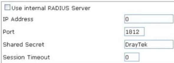
text_image
Use internal RADIUS Server IP Address 0 Port 1812 Shared Secret DrayTek Session Timeout 0
Available settings are explained as follows:
| Item | Description |
| Use internal RADIUS Server | There is a RADIUS server built in VigorAP 902 which is used to authenticate the wireless client connecting to the access point. Check this box to use the internal RADIUS server for wireless security.Besides, if you want to use the external RADIUS server for authentication, do not check this box.Please refer to the section,3.12 RADIUS Server to configure settings for internal server of VigorAP 902. |
| IP Address | Enter the IP address of external RADIUS server. |
| Port | The UDP port number that the external RADIUS server is using. The default value is 1812, based on RFC 2138. |
| Shared Secret | The external RADIUS server and client share a secret that is used to authenticate the messages sent between them. Both sides must be configured to use the same shared secret. |
| Session Timeout | Set the maximum time of service provided before re-authentication. Set to zero to perform another authentication immediately after the first authentication has successfully completed. (The unit is second.) |
After finishing this web page configuration, please click OK to save the settings.
3.8.3 Access Control
For additional security of wireless access, the Access Control facility allows you to restrict the network access right by controlling the wireless LAN MAC address of client. Only the valid MAC address that has been configured can access the wireless LAN interface. By clicking the Access Control, a new web page will appear, as depicted below, so that you could edit the clients' MAC addresses to control their access rights (deny or allow).
Wireless LAN (2.4GHz) >> Access Control
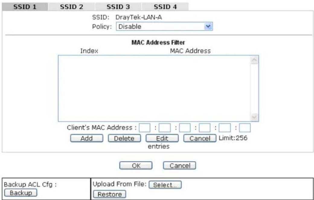
text_image
SSID 1 SSID 2 SSID 3 SSID 4 SSID: DrayTek-LAN-A Policy: Disable MAC Address Filter Index MAC Address Client's MAC Address : : : : : : : : Add Delete Edit Cancel Limit:256 entries OK Cancel Backup ACL Cfg : Backup Upload From File: Select... RestoreAvailable settings are explained as follows:
| Item | Description |
| Policy | Select to enable any one of the following policy or disable the policy.ChooseActivate MAC address filterto type in the MAC addresses for other clients in the network manually.ChooseBlocked MAC address filter,so that all of the devices with the MAC addresses listed on the MAC Address Filter table will be blocked and cannot access into VigorAP 902.Activate MAC address filterDisableActivate MAC address filterBlocked MAC address filter |
| MAC Address Filter | Display all MAC addresses that are edited before. |
| Client's MAC Address | Manually enter the MAC address of wireless client. |
| Add | Add a new MAC address into the list. |
| Delete | Delete the selected MAC address in the list. |
| Edit | Edit the selected MAC address in the list. |
| Cancel | Give up the access control set up. |
| Backup | Click it to store the settings (MAC addresses on MAC Address Filter table) on this page as a file. |
| Restore | Click it to restore the settings (MAC addresses on MAC Address Filter table) from an existed file. |
After finishing this web page configuration, please click OK to save the settings.
3.8.4 WPS
Open Wireless LAN>>WPS to configure the corresponding settings.
Wireless LAN (2.4GHz) >> WPS (Wi-Fi Protected Setup)
Enable WPS
Wi-Fi Protected Setup Information
| WPS Configured | Yes |
| WPS SSID | DrayTek-LAN-A |
| WPS Auth Mode | Mixed(WPA+WPA2)/PSK |
| WPS Encryp Type | TKIP/AES |
Device Configure
| Configure via Push Button | Start PBC | |
| Configure via Client PinCode | Start PIN |
Status: Not used
Note: WPS can help your wireless client automatically connect to the Access point.
: WPS is Disabled.
Q: WPS is Enabled.
: Waiting for WPS requests from wireless clients.
Available settings are explained as follows:
| Item | Description |
| Enable WPS | Check this box to enable WPS setting. |
| WPS Configured | Display related system information for WPS. If the wireless security (encryption) function of VigorAP 902 is properly configured, you can see ‘Yes’ message here. |
| WPS SSID | Display current selected SSID. |
| WPS Auth Mode | Display current authentication mode of the VigorAP 902r. Only WPA2/PSK and WPA/PSK support WPS. |
| WPS Encryp Type | Display encryption mode (None, WEP, TKIP, AES, etc.) of VigorAP 902. |
| Configure via Push Button | Click Start PBC to invoke Push-Button style WPS setup procedure. VigorAP 902 will wait for WPS requests from wireless clients about two minutes. Both ACT and 2.4G WLAN LEDs on VigorAP 902 will blink quickly when WPS is in progress. It will return to normal condition after two minutes. (You need to setup WPS within two minutes) |
| Configure via Client PinCode | Type the PIN code specified in wireless client you wish to connect, and click Start PIN button. Both ACT and 2.4G WLAN LEDs on VigorAP 902 will blink quickly when WPS is in progress. It will return to normal condition after two minutes. (You need to setup WPS within two minutes). |
3.8.5 Advanced Setting
This page is to determine which algorithm will be selected for wireless transmission rate.
Wireless LAN (2.4GHz) >> Advanced Setting

text_image
Rate Adaptation Algorithm Fragment Length (256 - 2346) RTS Threshold (1 - 2347) Country Code New Old 2346 bytes 2347 bytes (Reference) OK CancelAvailable settings are explained as follows:
| Item | Description |
| Rate Adaptation Algorithm | Wireless transmission rate is adapted dynamically. Usually, performance of “new” algorithm is better than “old”. |
| Fragment Length | Set the Fragment threshold of wireless radio. Do not modify default value if you don’t know what it is, default value is 2346. |
| RTS Threshold | Minimize the collision (unit is bytes) between hidden stations to improve wireless performance.Set the RTS threshold of wireless radio. Do not modify default value if you don’t know what it is, default value is 2347. |
| Country Code | VigorAP broadcasts country codes by following the 802.11d standard. However, some wireless stations will detect / scan the country code to prevent conflict occurred. If conflict is detected, wireless station will be warned and is unable to make network connection. Therefore, changing the country code to ensure successful network connection will be necessary for some clients. |
3.8.6 AP Discovery
VigorAP 902 can scan all regulatory channels and find working APs in the neighborhood. Based on the scanning result, users will know which channel is clean for usage. Also, it can be used to facilitate finding an AP for a WDS link. Notice that during the scanning process (about 5 seconds), no client is allowed to connect to Vigor.
This page is used to scan the existence of the APs on the wireless LAN. Yet, only the AP which is in the same channel of VigorAP 902 can be found. Please click Scan to discover all the connected APs.
Wireless LAN (2.4GHz) >> Access Point Discovery
Access Point List
| Select SSID | BSSID | RSSI | Channel | Encryption | Authentication |
See Channel Statistics
Note: During the scanning process (about 5 seconds), no station is allowed to connect with the AP.
| AP's MAC Address | □:□:□:□:□ | AP's SSID |

Each item is explained as follows:
| Item | Description |
| SSID | Display the SSID of the AP scanned by VigorAP 902. |
| BSSID | Display the MAC address of the AP scanned by VigorAP 902. |
| RSSI | Display the signal strength of the access point. RSSI is the abbreviation of Received Signal Strength Indication. |
| Channel | Display the wireless channel used for the AP that is scanned by VigorAP 902. |
| Encryption | Display the encryption mode for the scanned AP. |
| Authentication | Display the authentication type that the scanned AP applied. |
| Scan | It is used to discover all the connected AP. The results will be shown on the box above this button |
| Channel Statistics | It displays the statistics for the channels used by APs. |
| AP's MAC Address | If you want the found AP applying the WDS settings, please type in the AP's MAC address. |
| AP's SSID | To specify an AP to be applied with WDS settings, you can specify MAC address or SSID for the AP. Here is the place that you can type the SSID of the AP. |
| Add | Click Repeater for the specified AP. Next, click Add. Later, the MAC address of the AP will be added and be shown on WDS settings page. |
3.8.7 WDS AP Status
VigorAP 902 can display the status such as MAC address, physical mode, power save and bandwidth for the working AP connected with WDS. Click Refresh to get the newest information.
Wireless LAN (2.4GHz) >> WDS AP Status
WDS AP List
| AID | MAC Address | 802.11 Physical Mode | Power Save | Bandwidth |
| 1 | 00:50:7F:C9:76:0C | CCK | OFF | 20M |
Refresh
3.8.8 WMM Configuration
WMM is an abbreviation of Wi-Fi Multimedia. It defines the priority levels for four access categories derived from 802.1d (prioritization tabs). The categories are designed with specific types of traffic, voice, video, best effort and low priority data. There are four accessing categories - AC_BE, AC_BK, AC_VI and AC_VO for WMM.
Wireless LAN (2.4GHz) >> WMM Configuration
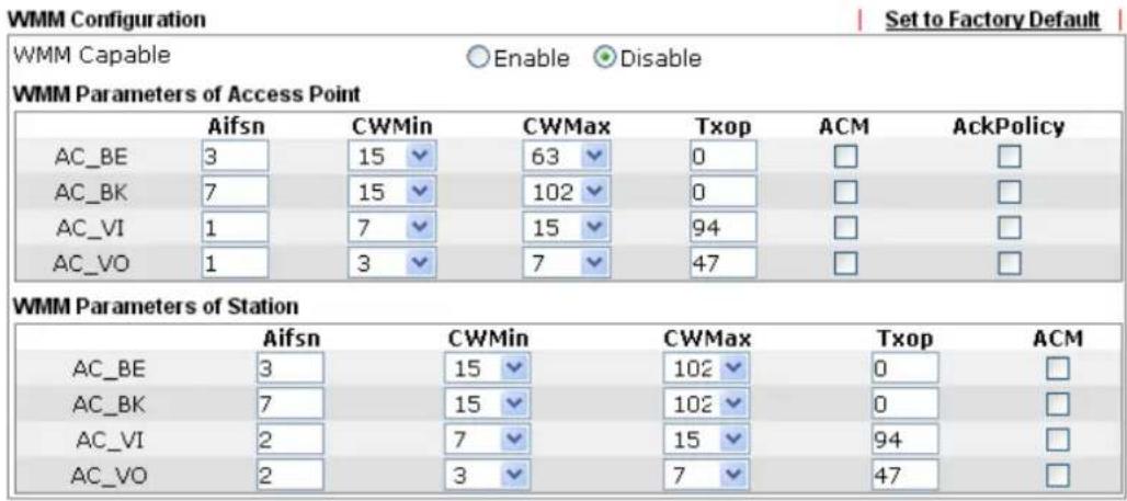
text_image
WMM Configuration Set to Factory Default WMM Capable Enable Disable WMM Parameters of Access Point Aifsn CWMin CWMax Txop ACM AckPolicy AC_BE 3 15 63 0 □ □ AC_BK 7 15 102 0 □ □ AC_VI 1 7 15 94 □ □ AC_VO 1 3 7 47 □ □ WMM Parameters of Station Aifsn CWMin CWMax Txop ACM AC_BE 3 15 102 0 □ AC_BK 7 15 102 0 □ AC_VI 2 7 15 94 □ AC_VO 2 3 7 47 □
Available settings are explained as follows:
| Item | Description |
| WMM Capable | To apply WMM parameters for wireless data transmission, please click the Enable radio button. |
| Aifsn | It controls how long the client waits for each data transmission. Please specify the value ranging from 1 to 15. Such parameter will influence the time delay for WMM accessing categories. For the service of voice or video image, please set small value for AC_VI and AC_VO categories For the service of e-mail or web browsing, please set large value for AC_BE and AC_BK categories. |
| CWMin/CWMax | CWMin means contention Window-Min and CWMax means contention Window-Max. Please specify the value ranging from 1 to 15. Be aware that CWMax value must be greater than CWMin or equals to CWMin value. Both values will influence the time delay for WMM accessing categories. The difference between AC_VI and AC_VO categories must be smaller; however, the difference between AC_BE and AC_BK categories must be greater. |
| Txop | It means transmission opportunity. For WMM categories of AC_VI and AC_VO that need higher priorities in data transmission, please set greater value for them to get highest transmission opportunity. Specify the value ranging from 0 to 65535. |
| ACM | It is an abbreviation of Admission control Mandatory. It can restrict stations from using specific category class if it ischecked.Note:VigorAP 902 provides standard WMM configuration in the web page. If you want to modify the parameters, please refer to the Wi-Fi WMM standard specification. |
| AckPolicy | “Uncheck” (default value) the box means the AP will answer the response request while transmitting WMM packets through wireless connection. It can assure that the peer must receive the WMM packets.“Check” the box means the AP will not answer any response request for the transmitting packets. It will have better performance with lower reliability. |
After finishing this web page configuration, please click OK to save the settings.
3.8.9 Bandwidth Management
The downstream or upstream from FTP, HTTP or some P2P applications will occupy large of bandwidth and affect the applications for other programs. Please use Bandwidth Management to make the bandwidth usage more efficient.
Wireless LAN (2.4GHz) >> Bandwidth Management
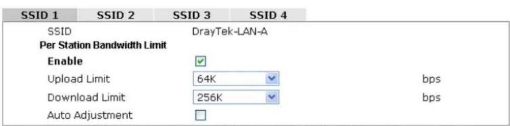
text_image
SSID 1 SSID 2 SSID 3 SSID 4 SSID DrayTek-LAN-A Per Station Bandwidth Limit Enable ✓ Upload Limit 64K bps Download Limit 256K bps Auto Adjustment □Note: 1. Download : Traffic going to any station. Upload : Traffic being sent from a wireless station. 2. Allow auto adjustment could make the best utilization of available bandwidth.

Available settings are explained as follows:
| Item | Description |
| SSID | Display the specific SSID name. |
| Enable | Check this box to enable the bandwidth management for clients. |
| Upload Limit | Define the maximum speed of the data uploading which will be used for the wireless stations connecting to VigorAP with the same SSID.Use the drop down list to choose the rate. If you choose User defined, you have to specify the rate manually. |
| Download Limit | Define the maximum speed of the data downloading which will be used for the wireless station connecting to VigorAP with the same SSID.Use the drop down list to choose the rate. If you choose User defined, you have to specify the rate manually. |
| Auto Adjustment | Check this box to have the bandwidth limit determined by the system automatically. |
After finishing this web page configuration, please click OK to save the settings.
3.8.10 Airtime Fairness
Airtime fairness is essential in wireless networks that must support critical enterprise applications.
Most of the applications are either symmetric or require more downlink than uplink capacity; telephony and email send the same amount of data in each direction, while video streaming and web surfing involve more traffic sent from access points to clients than the other way around. This is essential for ensuring predictable performance and quality-of-service, as well as allowing 802.11n and legacy clients to coexist on the same network. Without airtime fairness, offices using mixed mode networks risk having legacy clients slow down the entire network or letting the fastest client(s) crowd out other users.
With airtime fairness, every client at a given quality-of-service level has equal access to the network's airtime.
The wireless channel can be accessed by only one wireless station at the same time.
The principle behind the IEEE802.11 channel access mechanisms is that each station has equal probability to access the channel. When wireless stations have similar data rate, this principle leads to a fair result. In this case, stations get similar channel access time which is called airtime.
However, when stations have various data rate (e.g., 11g, 11n), the result is not fair. The slow stations (11g) work in their slow data rate and occupy too much airtime, whereas the fast stations (11n) become much slower.
Take the following figure as an example, both Station A(11g) and Station B(11n) transmit data packets through VigorAP 902. Although they have equal probability to access the wireless channel, Station B(11n) gets only a little airtime and waits too much because Station A(11g) spends longer time to send one packet. In other words, Station B(fast rate) is obstructed by Station A(slow rate).
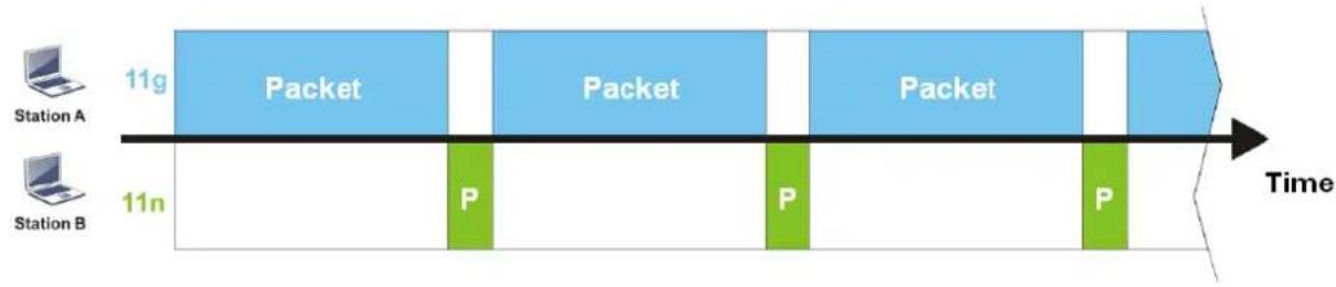
flowchart
graph LR
    A["Station A"] -->|11g| B["Packet"]
    C["Station B"] -->|11n| D["P"]
    B --> E["Packet"]
    E --> F["P"]
    F --> G["Packet"]
    G --> H["P"]
    H --> I["Time"]
To improve this problem, Airtime Fairness is added for VigorAP 902. Airtime Fairness function tries to assign similar airtime to each station (A/B) by controlling TX traffic. In the following figure, Station B(11n) has higher probability to send data packets than Station A(11g). By this way, Station B(fast rate) gets fair airtime and it's speed is not limited by Station A(slow rate).
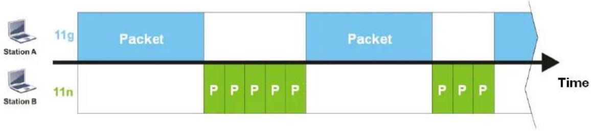
flowchart
graph LR
    A["Station A"] --> B["11g Packet"]
    C["Station B"] --> D["11n"]
    B --> E["Packet"]
    D --> F["P P P P P P"]
    E --> G["Time"]
    F --> G
    G --> H["Packet"]
    H --> I["11g Packet"]
    I --> J["11n"]
It is similar to automatic Bandwidth Limit. The dynamic bandwidth limit of each station depends on instant active station number and airtime assignment. Please note that Airtime Fairness of 2.4GHz and 5GHz are independent. But stations of different SSIDs function together, because they all use the same wireless channel. IN SPECIFIC ENVIRONMENTS, this function can reduce the bad influence of slow wireless devices and improve the overall wireless performance.
Suitable environment:
(1) Many wireless stations.
(2) All stations mainly use download traffic.
(3) The performance bottleneck is wireless connection.
Wireless LAN (2.4GHz) >> Airtime Fairness

Enable Airtime Fairness
Triggering Client Number (2-64) 2 (Default: 2)
Note: Please enable or disable this function according to the real situation and user experience. It is NOT suitable for all environments.

Cancel
Available settings are explained as follows:
| Item | Description |
| Enable Airtime Fairness | Try to assign similar airtime to each wireless station by controlling TX traffic.Airtime Fairness – Click the link to display the following screen of airtime fairness note.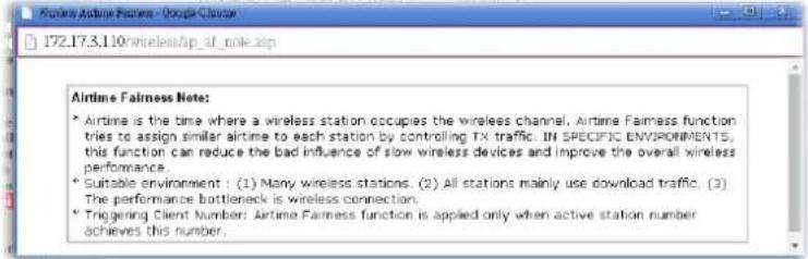 Triggering Client Number –Airtime Fairness function is applied only when active station number achieves this number. Triggering Client Number –Airtime Fairness function is applied only when active station number achieves this number. |
After finishing this web page configuration, please click OK to save the settings.
Note: Airtime Fairness function and Bandwidth Limit function should be mutually exclusive. So their webs have extra actions to ensure these two functions are not enabled simultaneously.
3.8.11 Station Control
Station Control is used to specify the duration for the wireless client to connect and reconnect VigorAP. If such function is not enabled, the wireless client can connect VigorAP until it shuts down.
Such feature is especially useful for free Wi-Fi service. For example, a coffee shop offers free Wi-Fi service for its guests for one hour every day. Then, the connection time can be set as “1 hour” and reconnection time can be set as “1 day”. Thus, the guest can finish his job within one hour and will not occupy the wireless network for a long time.
Note: Up to 300 Wireless Station records are supported by VigorAP.
Wireless LAN (2.4GHz) >> Station Control
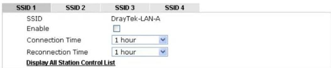
text_image
SSID 1 SSID 2 SSID 3 SSID 4 SSID DrayTek-LAN-A Enable Connection Time 1 hour Reconnection Time 1 hour Display All Station Control ListNote: Once the feature is enabled, the connection time quota will apply to each wireless client (identified by MAC address).

Available settings are explained as follows:
| Item | Description |
| SSID | Display the SSID that the wireless station will use it to connect with Vigor router. |
| Enable | Check the box to enable the station control function. |
| Connection Time / Reconnection Time | Use the drop down list to choose the duration for the wireless client connecting /reconnecting to Vigor router. Or, type the duration manually when you chooseUser defined. |
| Display All Station Control List | All the wireless stations connecting to Vigor router by using such SSID will be listed on Station Control List. |
After finishing all the settings here, please click OK to save the configuration.
3.8.12 Roaming
The network signal for a single wireless access point might be limited by its coverage range. Therefore, if you want to expand the wireless network in a large exhibition with a quick method, you can install multiple access points with enabling the Roaming feature for each AP to reach the purpose of expanding wireless signals seamlessly.
These access points connecting for each other shall be verified by pre-authentication. This page allows you to enable the roaming feature and the pre-authentication.
Wireless LAN (2.4GHz) >> Roaming
AP-assisted Client Roaming Parameters

text_image
Minimum Basic Rate 1 Mbps Disable RSSI Requirement Strictly Minimum RSSI -73 dBm (42 %) (Default: -73) Minimum RSSI -66 dBm (60 %) (Default: -66) with Adjacent AP RSSI over 5 dBm (Default: 5)Fast Roaming(WPA/802.1x)

text_image
Enable PMK Caching : Cache Period 10 minute(s) (10 ~ 600) (Default: 10) Pre-Authentication
Available settings are explained as follows:
| Item | Description |
| AP-assisted Client Roaming Parameters | When the link rate of wireless station is too low or the signal received by the wireless station is too worse, VigorAP 902 will automatically detect (based on the link rate and RSSI requirement) and cut off the network connection for that wireless station to assist it to connect another Wireless AP to get better signal. Minimum Basic Rate - Check the box to use the drop down list to specify a basic rate (Mbps). When the link rate of the wireless station is below such value, VigorAP 902 will terminate the network connection for that wireless station. Disable RSSI Requirement - If it is selected, VigorAP will not terminate the network connection based on RSSI. Strictly Minimum RSSI - VigorAP uses RSSI (received signal strength indicator) to decide to terminate the network connection of wireless station. When the signal strength is below the value (dBm) set here, VigorAP 902 will terminate the network connection for that wireless station. Minimum RSSI - When the signal strength of the wireless station is below the value (dBm) set here and adjacent AP (must be DrayTek AP and support such feature too) with higher signal strength value (defined in the field of With Adjacent AP RSSI over) is detected by VigorAP 902, VigorAP 902 will terminate the network connection for that wireless station. Later, thewireless station can connect to the adjacent AP (with better RSSI).● With Adjacent AP RSSI over – Specify a value as a threshold. |
| Fast Roaming (WPA/802.1x) | Enable – Check the box to enable fast roaming configuration.PMK Cache Period - Set the expire time of WPA2 PMK (Pairwise master key) cache. PMK Cache manages the list from the BSSIDs in the associated SSID with which it has pre-authenticated. Such feature is available for WPA2/802.1 mode.Pre-Authentication - Enables a station to authenticate to multiple APs for roaming securer and faster. With the pre-authentication procedure defined in IEEE 802.11i specification, the pre-four-way-handshake can reduce handoff delay perceivable by a mobile node. It makes roaming faster and more secure. (Only valid in WPA2)Enable - Enable IEEE 802.1X Pre-Authentication.Disable - Disable IEEE 802.1X Pre-Authentication. |
After finishing this web page configuration, please click OK to save the settings.
3.8.13 Band Steering
Band Steering detects if the wireless clients are capable of 5GHz operation, and steers them to that frequency. It helps to leave 2.4GHz band available for legacy clients, and improves users experience by reducing channel utilization.
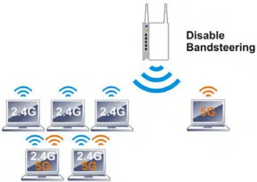
flowchart
graph TD
    A["Disabling Bandsteering"] --> B["Router"]
    B --> C["5G"]
    C --> D["2.4G 5G"]
    C --> E["2.4G 5G"]
    C --> F["2.4G 5G"]
    C --> G["2.4G 5G"]
    style A fill:#f9f,stroke:#333
    style B fill:#ccf,stroke:#333
    style C fill:#cfc,stroke:#333
    style D fill:#fcc,stroke:#333
    style E fill:#cff,stroke:#333
    style F fill:#ffc,stroke:#333
    style G fill:#fcc,stroke:#333
If dual-band is detected, the AP will let the wireless client connect to less congested wireless LAN, such as 5GHz to prevent from network congestion.
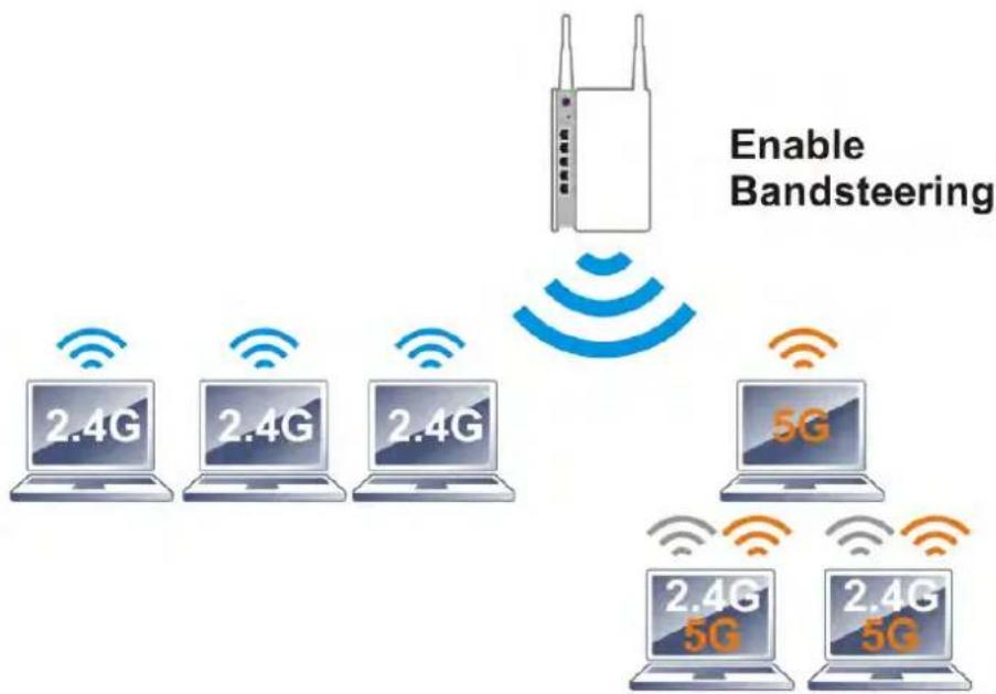
flowchart
graph TD
    A["Router"] -->|Enable Bandsteering| B["2.4G Laptop"]
    A -->|Enable Bandsteering| C["2.4G Laptop"]
    A -->|Enable Bandsteering| D["2.4G Laptop"]
    A -->|Enable Bandsteering| E["5G Laptop"]
    A -->|Enable Bandsteering| F["2.4G 5G Laptop"]
    A -->|Enable Bandsteering| G["2.4G 5G Laptop"]
Note: To make Band Steering work successfully, SS1D and security on 2.4GHz also MUST be broadcasted on 5GHz.
Open Wireless LAN (2.4GHz)>>Band Steering to get the following web page:
Wireless LAN >> Band Steering
Enable Band Steering Check Time for WLAN Client 5G Capability 15 second(s) (1 \~ 60) (Default: 15)
Note: Please setup at least one pair of 2.4GHz and 5GHz Wireless LAN with the same SSID and security.
OK Cancel
Available settings are explained as follows:
| Item | Description |
| Enable Band Steering | If it is enabled, VigorAP will detect if the wireless client is capable of dual-band or not within the time limit.Check Time.... – If the wireless station does not have the capability of 5GHz network connection, the system shall wait and check for several seconds (15 seconds, in default) to make the 2.4GHz network connection. Specify the time limit for VigorAP to detect the wireless client. |
After finishing this web page configuration, please click OK to save the settings.
Below shows how Band Steering works.
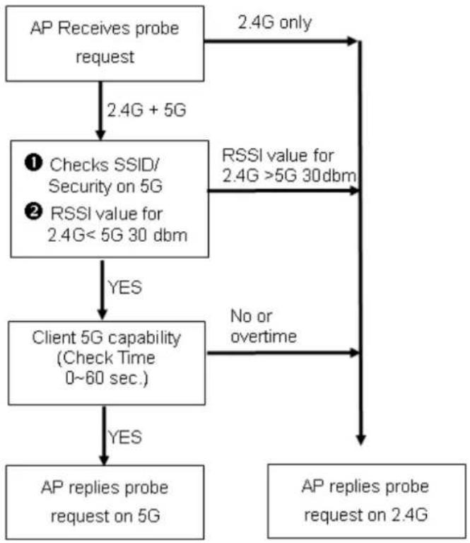
flowchart
graph TD
    A["AP Receives probe request"] -->|2.4G + 5G| B["① Checks SSID/Security on 5G"]
    A -->|2.4G only| C["RSSI value for 2.4G >5G 30 dbm"]
    B -->|YES| D["Client 5G capability (Check Time 0~60 sec.)"]
    B -->|No or overtime| E["AP replies probe request on 2.4G"]
    D -->|YES| F["AP replies probe request on 5G"]
    D -->|No or overtime| E
How to Use Band Steering?
- Open Wireless LAN(2.4GHz)>>Band Steering.
- Check the box of Enable Band Steering and use the default value (15) for check time setting.
Wireless LAN >> Band Steering
Enable Band Steering Check Time for WLAN Client 5G Capability 15 second(s) (1 \~ 60) (Default: 15)
Note: Please setup at least one pair of 2.4GHz and 5GHz Wireless LAN with the same SSID and security.
OK Cancel
- Click OK to save the settings.
- Open Wireless LAN (2.4GHz)>>General Setup and Wireless LAN (5GHz)>>General Setup. Configure SSID as ap902-BandSteering for both pages. Click OK to save the settings.
Wireless LAN (2.4GHz) >> General Setup
General Setting ( IEEE 802.11 )
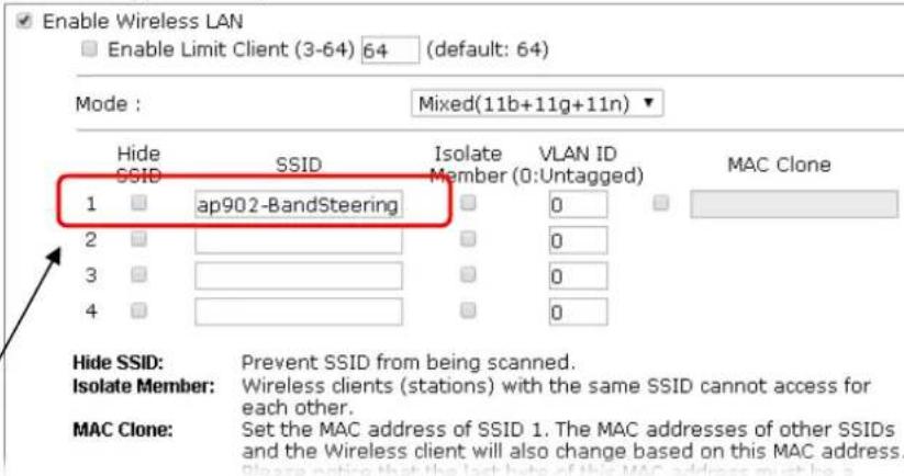
text_image
Enable Wireless LAN Enable Limit Client (3-64) 64 (default: 64) Mode : Mixed(11b+11g+11n) Hide SSID SSID Isolate VLAN ID Member (0:Untagged) MAC Clone 1 ap902-BandSteering 2 3 4 Hide SSID: Prevent SSID from being scanned. Isolate Member: Wireless clients (stations) with the same SSID cannot access for each other. MAC Clone: Set the MAC address of SSID 1. The MAC addresses of other SSIDs and the Wireless client will also change based on this MAC address. Please notice that the last date of this MAC address must be aSame value for 2.4GHz and 5GHz
Wireless LAN (5GHz) >> General Setup
General Setting ( IEEE 802.11 )
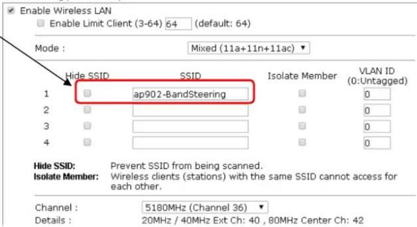
text_image
Enable Wireless LAN Enable Limit Client (3-64) 64 (default: 64) Mode : Mixed (11a+11n+11ac) Hide SSID SSID Isolate Member VLAN ID 1 ap902-BandSteering 0 2 3 4 Hide SSID: Prevent SSID from being scanned. Isolate Member: Wireless clients (stations) with the same SSID cannot access for each other. Channel : 5180MHz (Channel 36) Details : 20MHz / 40MHz Ext Ch: 40 , 80MHz Center Ch: 42- Open Wireless LAN (2.4GHz)>>Security and Wireless LAN (5GHz)>>Security. Configure Security as 12345678 for both pages. Click OK to save the settings.
Wireless LAN (2.4GHz) >> Security Settings

text_image
SSID 1 SSID 2 SSID 3 SSID 4 SSID ap902-BandSteering Mode Mixed(WPA+WPA2)/PSK Set up RADIUS Server if 802.1x is enabled. WPA WPA Algorithms TKIP AES TKIP/AES Pass Phrase •••••• Key Renewal Interval 3600 seconds WEP Key 1: Key 2: Key 3: Key 4: 802.1x WEP Disable Enable Hex Hex Hex HexSame value for 2.4GHz and 5GHz
Wireless LAN (5GHz) >> Security Settings
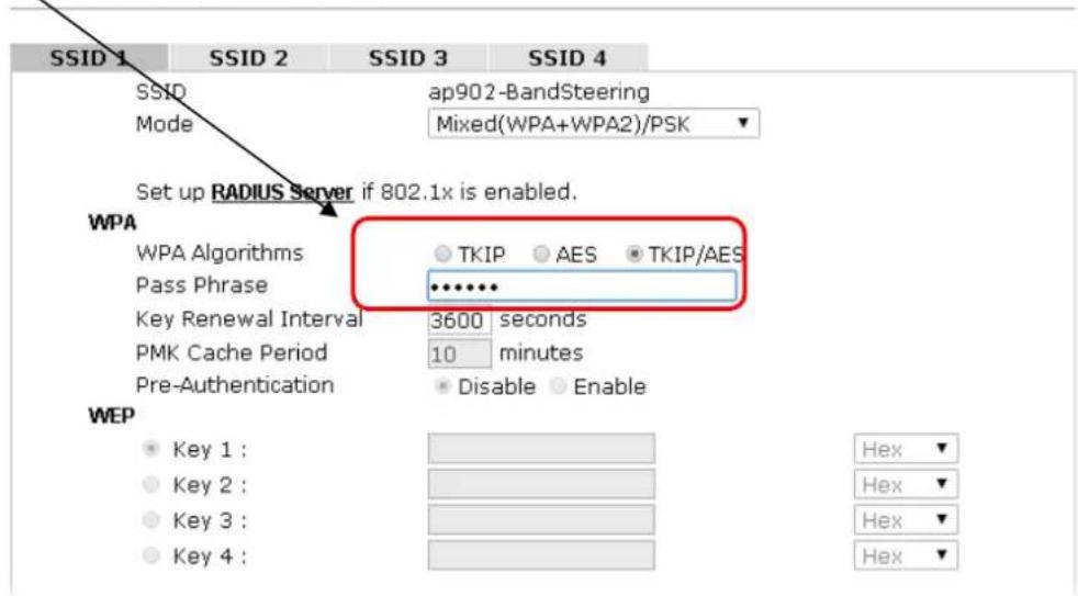
text_image
SSID 1 SSID 2 SSID 3 SSID 4 SSID ap902-BandSteering Mode Mixed(WPA+WPA2)/PSK Set up RADIUS Server if 802.1x is enabled. WPA WPA Algorithms TKIP AES TKIP/AES Pass Phrase ••••••• Key Renewal Interval 3600 seconds PMK Cache Period 10 minutes Pre-Authentication Disable Enable WEP Key 1 : Key 2 : Key 3 : Key 4 : Hex Hex Hex Hex- Now, VigorAP 902 will let the wireless clients connect to less congested wireless LAN, such as 5GHz to prevent from network congestion.
3.8.14 Station List
Station List provides the knowledge of connecting wireless clients now along with its status code.
General
Display general information (e.g., MAC Address, SSID, Auth, Encrypt, TX/RX Rate) for the station.
Wireless LAN (2.4GHz) >> Station List
Station List
| General | Advanced | Control | Neighbor | |||
| Index | MAC Address | Vendor | RSSI | Approx. Distance | SSID | Visit Time |
| 1 | DA:A1:19:E2:65:AD | 5%(-88dBm) | 141.25m | N/A | 0d:0h: | |
| 2 | 00:50:7F:F0:BD:2B | DrayTek | 52%(-69dBm) | 15.85m | N/A | 0d:0h: |
| 3 | 00:50:7F:37:6D:E5 | DrayTek | 47%(-71dBm) | 19.95m | N/A | 0d:0h: |
| 4 | 1C:4B:D6:8B:9C:00 | Azurewav | 18%(-83dBm) | 79.43m | N/A | 0d:1h: |
| 5 | 00:15:AF:A5:24:A0 | Azurewav | 26%(-79dBm) | 50.12m | N/A | 0d:0h: |
| 6 | B0:34:95:22:50:FD | Apple | 47%(-71dBm) | 19.95m | N/A | 0d:0h: |
| 7 | B4:52:7E:D6:68:9D | Sony | 20%(-82dBm) | 70.79m | N/A | 0d:0h: |
| 8 | 00:1F:3C:51:9C:55 | Intel | 39%(-74dBm) | 28.18m | N/A | 0d:1h: |
| Refresh | ||||||
| Add to Access Control :Client's MAC Address : □ : □ : □ : □ : □ : □ | ||||||
Note: 1. Approx. Distance is calculated by actual signal strength of device detected. Inaccuracy might occur based on barrier encountered.
2. Due to the differences in signal strength for different devices, the calculated value of approximate distance also might be different.
3. Trademarks and brand names are the properties of their respective owners.
Add
Available settings are explained as follows:
| Item | Description |
| MAC Address | Display the MAC Address for the connecting client. |
| Hostname | Display the host name of the connecting client. |
| SSID | Display the SSID that the wireless client connects to. |
| Auth | Display the authentication that the wireless client uses for connection with such AP. |
| Encrypt | Display the encryption mode used by the wireless client. |
| Tx Rate/Rx Rate | Display the transmission /receiving rate for packets. |
| Refresh | Click this button to refresh the status of station list. |
| Add to Access Control | Client's MAC Address - For additional security of wireless access, the Access Control facility allows you to restrict the network access right by controlling the wireless LAN MAC address of client. Only the valid MAC address that has been configured can access the wireless LAN interface. |
| Add | Click this button to add current typed MAC address into Access Control. |
Advanced
Display more information (e.g., AID, PSM, WMM, RSSI PhMd, BW, MCS, Rate) for the station.
Control
Display connection and reconnection time of the wireless stations.
Neighbor
Display more information for the neighboring wireless stations.
3.9 Wireless LAN Settings for Universal Repeater Mode
When you choose Universal Repeater as the operation mode, the Wireless LAN menu items will include General Setup, Security, Access Control, WPS, Advanced Setting, AP Discovery, Universal Repeater, WMM Configuration, Bandwidth Management, Airtime Fairness, Station Control, Roaming, Band Steering and Station List.
Wireless LAN (2.4GHz)
General Setup
Security
Access Control
WPS
Advanced Setting
AP Discovery
Universal Repeater
WMM Configuration
Bandwidth Management
Airtime Fairness
Station Control
Roaming
Band Steering
Station List
3.9.1 General Setup
By clicking the General Setup, a new web page will appear so that you could configure the SSID and the wireless channel.
Please refer to the following figure for more information.
Wireless LAN (2.4GHz) >> General Setup
General Setting ( IEEE 802.11 )
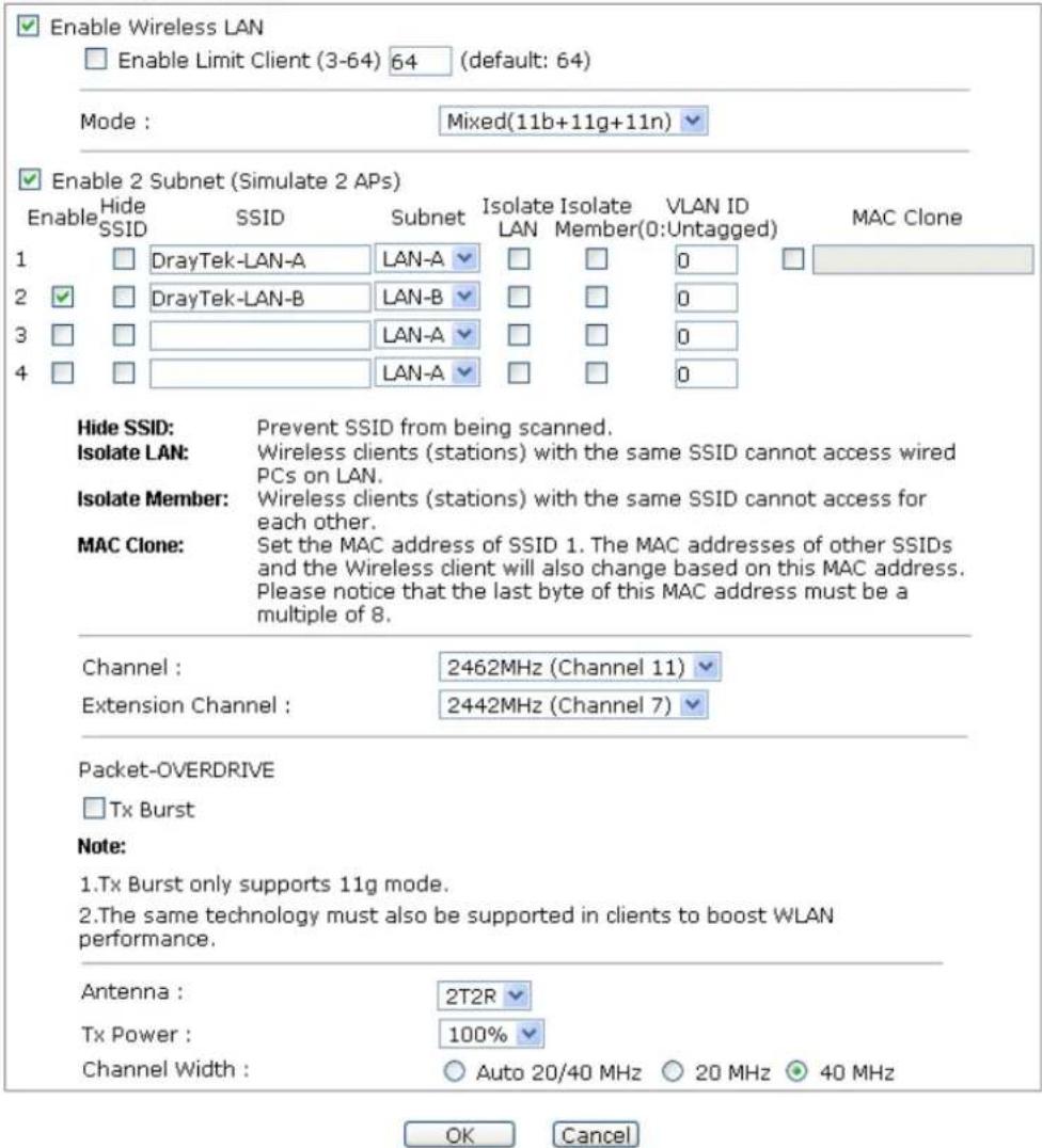
text_image
Enable Wireless LAN Enable Limit Client (3-64) 64 (default: 64) Mode : Mixed(11b+11g+11n) Enable 2 Subnet (Simulate 2 APs) Enable Hide SSID SSID Subnet Isolate Isolate VLAN ID MAC Clone 1 DrayTek-LAN-A LAN-A LAN-A 0 2 DrayTek-LAN-B LAN-B LAN-A 0 3 LAN-A 0 4 LAN-A 0 Hide SSID: Prevent SSID from being scanned. Isolate LAN: Wireless clients (stations) with the same SSID cannot access wired PCs on LAN. Isolate Member: Wireless clients (stations) with the same SSID cannot access for each other. MAC Clone: Set the MAC address of SSID 1. The MAC addresses of other SSIDs and the Wireless client will also change based on this MAC address. Please notice that the last byte of this MAC address must be a multiple of 8. Channel : 2462MHz (Channel 11) Extension Channel : 2442MHz (Channel 7) Packet-OVERDRIVE Tx Burst Note: 1.Tx Burst only supports 11g mode. 2.The same technology must also be supported in clients to boost WLAN performance. Antenna : 2T2R Tx Power : 100% Channel Width : Auto 20/40 MHz 20 MHz 40 MHz OK CancelAvailable settings are explained as follows:
| Item | Description |
| Enable Wireless LAN | Check the box to enable wireless function. |
| Enable Limit Client | Check the box to set the maximum number of wireless stations which try to connect Internet through VigorAP. The number you can set is from 3 to 64. |
| Mode | At present, VigorAP 902 can connect to 11b only, 11g only, 11n only, Mixed (11b+11g), Mixed (11g+11n) and Mixed (11b+11g+11n) stations simultaneously. Simply choose Mixed (11b+11g+11n) mode.Mixed(11b+11g+11n)11b Only11g Only11n OnlyMixed(11b+11g)Mixed(11g+11n)Mixed(11b+11g+11n) |
| Enable 2 Subnet(Simulate 2 APs) | Check the box to enable the function for two independent subnets. Once you enable this function, LAN-A and LAN-B would be independent. Next, you can connect one router in LAN-A, and another router in LAN-B. Such mechanism can make you feeling that you have two independent AP/subnet functions in one VigorAP 902.If you disable this function, LAN-A and LAN-B ports are in the same domain. You could only connect one router (no matter connecting to LAN-A or LAN-B) in this environment. |
| Hide SSID | Check it to prevent from wireless sniffing and make it harder for unauthorized clients or STAs to join your wireless LAN. Depending on the wireless utility, the user may only see the information except SSID or just cannot see any thing about VigorAP 902 while site surveying. The system allows you to set four sets of SSID for different usage. |
| SSID | Set a name for VigorAP 902 to be identified. Default settings are DrayTek-LAN-A and DrayTek-LAN-B. When Enable 2 Subnet is enabled, you can specify subnet interface (LAN-A or LAN-B) for each SSID by using the drop down menu. |
| Subnet | Choose LAN-A or LAN-B for each SSID. If you choose LAN-A, the wireless clients connecting to this SSID could only communicate with LAN-A. |
| Isolate LAN | Check this box to make the wireless clients (stations) with the same SSID not accessing for wired PC in LAN. |
| Isolate Member | Check this box to make the wireless clients (stations) with the same SSID not accessing for each other. |
| VLAN ID | Type the value for such SSID. Packets transferred from such SSID to LAN will be tagged with the number.If your network uses VLANs, you can assign the SSID to a VLAN on your network. Client devices that associate using the SSID are grouped into this VLAN. The VLAN ID range is from 3 to 4095. The VLAN ID is 0 by default, it means disabling the VLAN function for the SSID. |
| MAC Clone | Check this box and manually enter the MAC address of the device with SSID 1. The MAC address of other SSIDs will change based on this MAC address. |
| Channel | Means the channel of frequency of the wireless LAN. You may switch channel if the selected channel is under serious interference. If you have no idea of choosing the frequency, please selectAutoSelectto let system determine for you. |
| Extension Channel | With 802.11n, there is one option to double the bandwidth per channel. The available extension channel options will be varied according to theChannelselected above. Configure the extension channel you want. |
| Rate | If you choose 11g Only, 11b Only or 11n Only, such feature will be available for you to set data transmission rate. |
| Packet-OVERDRIVE | This feature can enhance the performance in data transmission about 40%* more (by checking Tx Burst). It is active only when both sides of Access Point and Station (in wireless client) invoke this function at the same time. That is, the wireless client must support this feature and invoke the function, too.Note:Vigor N61 wireless adapter supports this function. Therefore, you can use and install it into your PC for matching with Packet-OVERDRIVE (refer to the following picture of Vigor N61 wireless utility window, chooseEnablefor TxBURSTon the tab ofOption).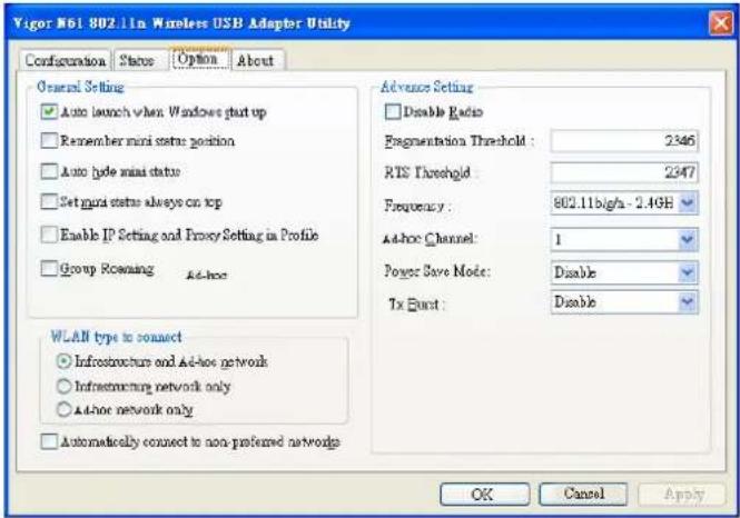 |
| Antenna | VigorAP 902 can be attached with two antennas to have good data transmission via wireless connection. However, if you have only one antenna attached, please choose 1T1R. |
| Tx Power | The default setting is the maximum (100%). Lowering down the value may degrade range and throughput of wireless.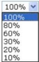 |
| Channel Width | Auto 20/40 MHZ– the device will use 20Mhz or 40Mhz for data transmission and receiving according to the station capability. Such channel can increase the performance for datatransmission. |
| 20 MHZ- the device will use 20Mhz for data transmission and receiving between the AP and the stations. | |
| 40 MHZ- the device will use 40Mhz for data transmission and receiving between the AP and the stations. |
After finishing this web page configuration, please click OK to save the settings.
3.9.2 Security
This page allows you to set security with different modes for SSID 1, 2, 3 and 4 respectively. After configuring the correct settings, please click OK to save and invoke it.
By clicking the Security Settings, a new web page will appear so that you could configure the settings.
Wireless LAN (2.4GHz) >> Security Settings
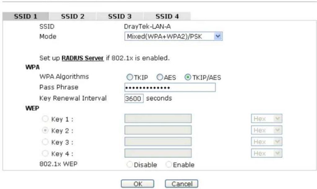
text_image
SSID 1 SSID 2 SSID 3 SSID 4 SSID DrayTek-LAN-A Mode Mixed(WPA+WPA2)/PSK Set up RADIUS Server if 802.1x is enabled. WPA WPA Algorithms ○ TKIP ○ AES ● TKIP/AES Pass Phrase ••••••••••• Key Renewal Interval 3600 seconds WEP ○ Key 1 : ● Key 2 : ○ Key 3 : ○ Key 4 : 802.1x WEP ○ Disable ○ Enable Hex Hex Hex Hex OK CancelAvailable settings are explained as follows:
| Item | Description |
| Mode | There are several modes provided for you to choose. |
| DisableDisableWEPWPA/PSKWPA2/PSKMixed(WPA+WPA2)/PSKWEP/802.1xWPA/802.1xWPA2/802.1xMixed(WPA+WPA2)/802.1x | |
| Disable - The encryption mechanism is turned off.WEP - Accepts only WEP clients and the encryption key should be entered in WEP Key.WPA/PSK or WPA2/PSK or Mixed (WPA+WPA2)/PSK - Accepts only WPA clients and the encryption key should be entered in PSK. The WPA encrypts each frame transmitted from the radio using the key, which either PSK (Pre-Shared Key) entered manually in this field below or automatically negotiated via 802.1x authentication.WEP/802.1x - The built-in RADIUS client feature enables VigorAP 902 to assist the remote dial-in user or a wireless station and the RADIUS server in performing mutualauthentication. It enables centralized remote access authentication for network management.The WPA encrypts each frame transmitted from the radio using the key, which either PSK (Pre-Shared Key) entered manually in this field below or automatically negotiated via 802.1x authentication. Select WPA, WPA2 or Auto as WPA mode.WPA/802.1x - The WPA encrypts each frame transmitted from the radio using the key, which either PSK (Pre-Shared Key) entered manually in this field below or automatically negotiated via 802.1x authentication.WPA2/802.1x - The WPA encrypts each frame transmitted from the radio using the key, which either PSK (Pre-Shared Key) entered manually in this field below or automatically negotiated via 802.1x authentication. | |
| WPA Algorithms | Select TKIP, AES or TKIP/AES as the algorithm for WPA. Such feature is available for WPA2/802.1x, WPA/802.1x, WPA/PSK or WPA2/PSK or Mixed (WPA+WPA2)/PSK mode. |
| Pass Phrase | Either 8~63 ASCII characters, such as 012345678..(or 64 Hexadecimal digits leading by 0x, such as "0x321253abcde..."). Such feature is available for WPA/PSK or WPA2/PSK or Mixed (WPA+WPA2)/PSK mode. |
| Key Renewal Interval | WPA uses shared key for authentication to the network. However, normal network operations use a different encryption key that is randomly generated. This randomly generated key that is periodically replaced. Enter the renewal security time (seconds) in the column. Smaller interval leads to greater security but lower performance. Default is 3600 seconds. Set 0 to disable re-key. Such feature is available for WPA2/802.1,WPA/802.1x, WPA/PSK or WPA2/PSK or Mixed (WPA+WPA2)/PSK mode. |
| Key 1 - Key 4 | Four keys can be entered here, but only one key can be selected at a time. The format of WEP Key is restricted to 5 ASCII characters or 10 hexadecimal values in 64-bit encryption level, or restricted to 13 ASCII characters or 26 hexadecimal values in 128-bit encryption level. The allowed content is the ASCII characters from 33(!) to 126(~) except '#' and ';'. Such feature is available for WEP mode.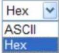 |
| 802.1x WEP | Disable - Disable the WEP Encryption. Data sent to the AP will not be encrypted.Enable - Enable the WEP Encryption.Such feature is available for WEP/802.1x mode. |
Click the link of RADIUS Server to access into the following page for more settings.
RADIUS Server
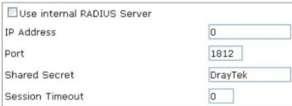
text_image
Use internal RADIUS Server IP Address 0 Port 1812 Shared Secret DrayTek Session Timeout 0
Available settings are explained as follows:
| Item | Description |
| Use internal RADIUS Server | There is a RADIUS server built in VigorAP 902 which is used to authenticate the wireless client connecting to the access point. Check this box to use the internal RADIUS server for wireless security.Besides, if you want to use the external RADIUS server for authentication, do not check this box.Please refer to the section,3.12 RADIUS Server to configure settings for internal server of VigorAP 902. |
| IP Address | Enter the IP address of external RADIUS server. |
| Port | The UDP port number that the external RADIUS server is using. The default value is 1812, based on RFC 2138. |
| Shared Secret | The external RADIUS server and client share a secret that is used to authenticate the messages sent between them. Both sides must be configured to use the same shared secret. |
| Session Timeout | Set the maximum time of service provided before re-authentication. Set to zero to perform another authentication immediately after the first authentication has successfully completed. (The unit is second.) |
After finishing this web page configuration, please click OK to save the settings.
3.9.3 Access Control
For additional security of wireless access, the Access Control facility allows you to restrict the network access right by controlling the wireless LAN MAC address of client. Only the valid MAC address that has been configured can access the wireless LAN interface. By clicking the Access Control, a new web page will appear, as depicted below, so that you could edit the clients' MAC addresses to control their access rights (deny or allow).
Wireless LAN (2.4GHz) >> Access Control
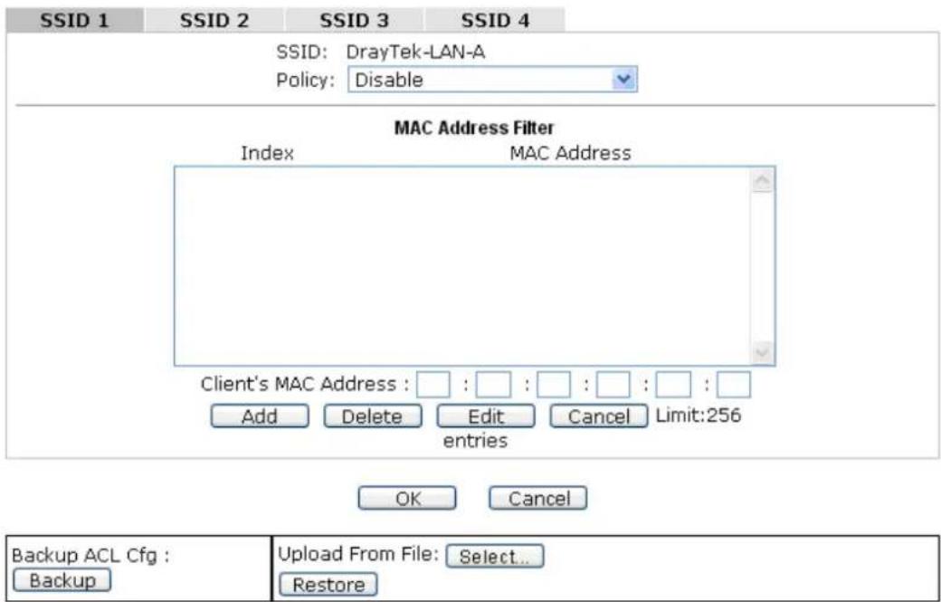
text_image
SSID 1 SSID 2 SSID 3 SSID 4 SSID: DrayTek-LAN-A Policy: Disable MAC Address Filter Index MAC Address Client's MAC Address : : : : : : : : Add Delete Edit Cancel Limit:256 entries OK Cancel Backup ACL Cfg : Backup Upload From File: Select... RestoreAvailable settings are explained as follows:
| Item | Description |
| Policy | Select to enable any one of the following policy or disable the policy.ChooseActivate MAC address filterto type in the MAC addresses for other clients in the network manually.ChooseBlocked MAC address filter,so that all of the devices with the MAC addresses listed on the MAC Address Filter table will be blocked and cannot access into VigorAP 902.Activate MAC address filterDisableActivate MAC address filterBlocked MAC address filter |
| MAC Address Filter | Display all MAC addresses that are edited before. |
| Client's MAC Address | Manually enter the MAC address of wireless client. |
| Add | Add a new MAC address into the list. |
| Delete | Delete the selected MAC address in the list. |
| Edit | Edit the selected MAC address in the list. |
| Cancel | Give up the access control set up. |
| Backup | Click it to store the settings (MAC addresses on MAC Address Filter table) on this page as a file. |
| Restore | Click it to restore the settings (MAC addresses on MAC Address Filter table) from an existed file. |
After finishing this web page configuration, please click OK to save the settings.
3.9.4 WPS
Open Wireless LAN>>WPS to configure the corresponding settings.
Wireless LAN (2.4GHz) >> WPS (Wi-Fi Protected Setup)
Enable WPS
Wi-Fi Protected Setup Information
| WPS Configured | Yes |
| WPS SSID | DrayTek-LAN-A |
| WPS Auth Mode | Mixed(WPA+WPA2)/PSK |
| WPS Encryp Type | TKIP/AES |
Device Configure
| Configure via Push Button | Start PBC | |
| Configure via Client PinCode | Start PIN |
Status: Idle
Note: WPS can help your wireless client automatically connect to the Access point.
: WPS is Disabled.
Q: WPS is Enabled.
: Waiting for WPS requests from wireless clients.
Available settings are explained as follows:
| Item | Description |
| Enable WPS | Check this box to enable WPS setting. |
| WPS Configured | Display related system information for WPS. If the wireless security (encryption) function of VigorAP 902 is properly configured, you can see ‘Yes’ message here. |
| WPS SSID | Display current selected SSID. |
| WPS Auth Mode | Display current authentication mode of the VigorAP 902. Only WPA2/PSK and WPA/PSK support WPS. |
| WPS Encryp Type | Display encryption mode (None, WEP, TKIP, AES, etc.) of VigorAP 902. |
| Configure via Push Button | Click Start PBC to invoke Push-Button style WPS setup procedure. VigorAP 902 will wait for WPS requests from wireless clients about two minutes. Both ACT and 2.4G WLAN LEDs on VigorAP 902 will blink quickly when WPS is in progress. It will return to normal condition after two minutes. (You need to setup WPS within two minutes) |
| Configure via Client PinCode | Type the PIN code specified in wireless client you wish to connect, and click Start PIN button. Both ACT and 2.4G WLAN LEDs on VigorAP 902 will blink quickly when WPS is in progress. It will return to normal condition after two minutes. (You need to setup WPS within two minutes). |
3.9.5 Advanced Setting
This page is to determine which algorithm will be selected for wireless transmission rate.
Wireless LAN (2.4GHz) >> Advanced Setting
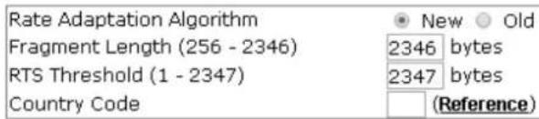
text_image
Rate Adaptation Algorithm Fragment Length (256 - 2346) RTS Threshold (1 - 2347) Country Code New Old 2346 bytes 2347 bytes (Reference)
Available settings are explained as follows:
| Item | Description |
| Rate Adaptation Algorithm | Wireless transmission rate is adapted dynamically. Usually, performance of “new” algorithm is better than “old”. |
| Fragment Length | Set the Fragment threshold of wireless radio. Do not modify default value if you don’t know what it is, default value is 2346. |
| RTS Threshold | Minimize the collision (unit is bytes) between hidden stations to improve wireless performance.Set the RTS threshold of wireless radio. Do not modify default value if you don’t know what it is, default value is 2347. |
| Country Code | VigorAP broadcasts country codes by following the 802.11d standard. However, some wireless stations will detect / scan the country code to prevent conflict occurred. If conflict is detected, wireless station will be warned and is unable to make network connection. Therefore, changing the country code to ensure successful network connection will be necessary for some clients. |
3.9.6 AP Discovery
VigorAP 902 can scan all regulatory channels and find working APs in the neighborhood. Based on the scanning result, users will know which channel is clean for usage. Also, it can be used to facilitate finding an AP for a WDS link. Notice that during the scanning process (about 5 seconds), no client is allowed to connect to Vigor.
This page is used to scan the existence of the APs on the wireless LAN. Yet, only the AP which is in the same channel of VigorAP 902 can be found. Please click Scan to discover all the connected APs.
Wireless LAN (2.4GHz) >> Access Point Discovery
Access Point List


See Channel Statistics
Note: During the scanning process (about 5 seconds), no station is allowed to connect with the AP.
AP's MAC Address

AP's SSID
Select as Universal Repeater: Select
Each item is explained as follows:
| Item | Description |
| SSID | Display the SSID of the AP scanned by VigorAP 902. |
| BSSID | Display the MAC address of the AP scanned by VigorAP 902. |
| RSSI | Display the signal strength of the access point. RSSI is the abbreviation of Received Signal Strength Indication. |
| Channel | Display the wireless channel used for the AP that is scanned by VigorAP 902. |
| Encryption | Display the encryption mode for the scanned AP. |
| Authentication | Display the authentication type that the scanned AP applied. |
| Scan | It is used to discover all the connected AP. The results will be shown on the box above this button |
| Channel Statistics | It displays the statistics for the channels used by APs. |
| AP's MAC Address | If you want the found AP applying the WDS settings, please type in the AP's MAC address. |
| AP's SSID | To specify an AP to be applied with WDS settings, you can specify MAC address or SSID for the AP. Here is the place that you can type the SSID of the AP. |
| Select as Universal Repeater | In Universal Repeater mode, WAN would work as station mode and the wireless AP can be selected as a universal repeater. Choose one of the wireless APs from the Scan list. |
3.9.7 Universal Repeater
The access point can act as a wireless repeater; it can be Station and AP at the same time. It can use Station function to connect to a Root AP and use AP function to serve all wireless stations within its coverage.
Note: While using Universal Repeater mode, the access point will demodulate the received signal. Please check if this signal is noise for the operating network, then have the signal modulated and amplified again. The output power of this mode is the same as that of WDS and normal AP mode.
Wireless LAN (2.4GHz) >> Universal Repeater
Universal Repeater Parameters
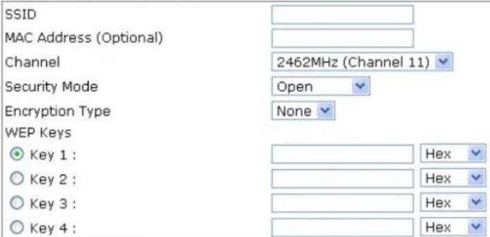
text_image
SSID MAC Address (Optional) Channel 2462MHz (Channel 11) Security Mode Open Encryption Type None WEP Keys Key 1 : Hex Key 2 : Hex Key 3 : Hex Key 4 : HexNote: If Channel is modified, the Channel setting of AP would also be changed.
Universal Repeater IP Configuration

text_image
Connection Type DHCP Device Name AP902 OK CancelAvailable settings are explained as follows:
| Item | Description |
| SSID | Set the name of access point that VigorAP 902 wants to connect to. |
| MAC Address(Optional) | Type the MAC address of access point that VigorAP 902 wants to connect to. |
| Channel | Means the channel of frequency of the wireless LAN. The default channel is 11. You may switch channel if the selected channel is under serious interference. If you have no idea of choosing the frequency, please selectAutoSelectto let system determine for you. |
| Security Mode | There are several modes provided for you to choose. Each mode will bring up different parameters (e.g., WEP keys, Pass Phrase) for you to configure. |
| Encryption Type for | This option is available when Open/Shared is selected as |
| Open/Shared | Security Mode.Choose None to disable the WEP Encryption. Data sent to the AP will not be encrypted. To enable WEP encryption for data transmission, please choose WEP.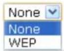 WEP Keys - Four keys can be entered here, but only one key can be selected at a time. The format of WEP Key is restricted to 5 ASCII characters or 10 hexadecimal values in 64-bit encryption level, or restricted to 13 ASCII characters or 26 hexadecimal values in 128-bit encryption level. The allowed content is the ASCII characters from 33(!) to 126(~) except '#' and ','. WEP Keys - Four keys can be entered here, but only one key can be selected at a time. The format of WEP Key is restricted to 5 ASCII characters or 10 hexadecimal values in 64-bit encryption level, or restricted to 13 ASCII characters or 26 hexadecimal values in 128-bit encryption level. The allowed content is the ASCII characters from 33(!) to 126(~) except '#' and ','. |
| Encryption Type for WPA/PSK and WPA2/PSK | This option is available when WPA/PSK or WPA2/PSK is selected as Security Mode.Select TKIP or AES as the algorithm for WPA. |
| Pass Phrase | Either 8~63 ASCII characters, such as 012345678 (or 64 Hexadecimal digits leading by 0x, such as "0x321253abcde..."). |
| Connection Type | Choose DHCP or Static IP as the connection mode.DHCP – The wireless station will be assigned with an IP from VigorAP.Static IP – The wireless station shall specify a static IP for connecting to Internet via VigorAP. |
| Device Name | This setting is available when Static DHCP is selected as Connection Type.Type a name for the router as identification. Simply use the default name. |
| IP Address | This setting is available when Static IP is selected as Connection Type.Type an IP address with the same network segment of the LAN IP setting of the router. Such IP shall be different with any IP address in LAN. |
| Subnet Mask | This setting is available when Static IP is selected as Connection Type. Type the subnet mask setting which shall be the same as the one configured in LAN for the router. |
| Default Gateway | This setting is available when Static IP is selected as Connection Type. Type the gateway setting which shall be the same as the default gateway configured in LAN for the router. |
After finishing this web page configuration, please click OK to save the settings.
3.9.8 WMM Configuration
WMM is an abbreviation of Wi-Fi Multimedia. It defines the priority levels for four access categories derived from 802.1d (prioritization tabs). The categories are designed with specific types of traffic, voice, video, best effort and low priority data. There are four accessing categories - AC_BE, AC_BK, AC_VI and AC_VO for WMM.
Wireless LAN (2.4GHz) >> WMM Configuration
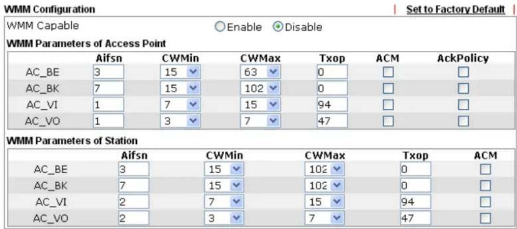
text_image
WMM Configuration Set to Factory Default WMM Capable Enable Disable WMM Parameters of Access Point Aifsn CWMin CWMax Txop ACM AckPolicy AC_BE 3 15 63 0 □ □ AC_BK 7 15 102 0 □ □ AC_VI 1 7 15 94 □ □ AC_VO 1 3 7 47 □ □ WMM Parameters of Station Aifsn CWMin CWMax Txop ACM AC_BE 3 15 102 0 □ AC_BK 7 15 102 0 □ AC_VI 2 7 15 94 □ AC_VO 2 3 7 47 □
Available settings are explained as follows:
| Item | Description |
| WMM Capable | To apply WMM parameters for wireless data transmission, please click the Enable radio button. |
| Aifsn | It controls how long the client waits for each data transmission. Please specify the value ranging from 1 to 15. Such parameter will influence the time delay for WMM accessing categories. For the service of voice or video image, please set small value for AC_VI and AC_VO categories For the service of e-mail or web browsing, please set large value for AC_BE and AC_BK categories. |
| CWMin/CWMax | CWMin means contention Window-Min and CWMax means contention Window-Max. Please specify the value ranging from 1 to 15. Be aware that CWMax value must be greater than CWMin or equals to CWMin value. Both values will influencethe time delay for WMM accessing categories. The difference between AC_VI and AC_VO categories must be smaller; however, the difference between AC_BE and AC_BK categories must be greater. |
| Txop | It means transmission opportunity. For WMM categories of AC_VI and AC_VO that need higher priorities in data transmission, please set greater value for them to get highest transmission opportunity. Specify the value ranging from 0 to 65535. |
| ACM | It is an abbreviation of Admission control Mandatory. It can restrict stations from using specific category class if it is checked.Note:VigorAP 902 provides standard WMM configuration in the web page. If you want to modify the parameters, please refer to the Wi-Fi WMM standard specification. |
| AckPolicy | “Uncheck” (default value) the box means the AP will answer the response request while transmitting WMM packets through wireless connection. It can assure that the peer must receive the WMM packets.“Check” the box means the AP will not answer any response request for the transmitting packets. It will have better performance with lower reliability. |
After finishing this web page configuration, please click OK to save the settings.
3.9.9 Bandwidth Management
The downstream or upstream from FTP, HTTP or some P2P applications will occupy large of bandwidth and affect the applications for other programs. Please use Bandwidth Management to make the bandwidth usage more efficient.
Wireless LAN (2.4GHz) >> Bandwidth Management
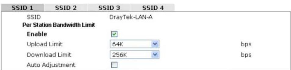
text_image
SSID 1 SSID 2 SSID 3 SSID 4 SSID DrayTek-LAN-A Per Station Bandwidth Limit Enable ✓ Upload Limit 64K bps Download Limit 256K bps Auto Adjustment □Note: 1. Download : Traffic going to any station. Upload : Traffic being sent from a wireless station. 2. Allow auto adjustment could make the best utilization of available bandwidth.

Available settings are explained as follows:
| Item | Description |
| SSID | Display the specific SSID name. |
| Enable | Check this box to enable the bandwidth management for clients. |
| Upload Limit | Define the maximum speed of the data uploading which will be used for the wireless stations connecting to VigorAP with the same SSID.Use the drop down list to choose the rate. If you choose User defined, you have to specify the rate manually. |
| Download Limit | Define the maximum speed of the data downloading which will be used for the wireless station connecting to VigorAP with the same SSID.Use the drop down list to choose the rate. If you choose User defined, you have to specify the rate manually. |
| Auto Adjustment | Check this box to have the bandwidth limit determined by the system automatically. |
After finishing this web page configuration, please click OK to save the settings.
3.9.10 Airtime Fairness
Airtime fairness is essential in wireless networks that must support critical enterprise applications.
Most of the applications are either symmetric or require more downlink than uplink capacity; telephony and email send the same amount of data in each direction, while video streaming and web surfing involve more traffic sent from access points to clients than the other way around. This is essential for ensuring predictable performance and quality-of-service, as well as allowing 802.11n and legacy clients to coexist on the same network. Without airtime fairness, offices using mixed mode networks risk having legacy clients slow down the entire network or letting the fastest client(s) crowd out other users.
With airtime fairness, every client at a given quality-of-service level has equal access to the network's airtime.
The wireless channel can be accessed by only one wireless station at the same time.
The principle behind the IEEE802.11 channel access mechanisms is that each station has equal probability to access the channel. When wireless stations have similar data rate, this principle leads to a fair result. In this case, stations get similar channel access time which is called airtime.
However, when stations have various data rate (e.g., 11g, 11n), the result is not fair. The slow stations (11g) work in their slow data rate and occupy too much airtime, whereas the fast stations (11n) become much slower.
Take the following figure as an example, both Station A(11g) and Station B(11n) transmit data packets through VigorAP 902. Although they have equal probability to access the wireless channel, Station B(11n) gets only a little airtime and waits too much because Station A(11g) spends longer time to send one packet. In other words, Station B(fast rate) is obstructed by Station A(slow rate).
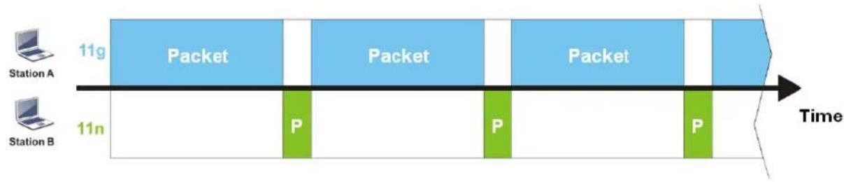
flowchart
graph LR
    A["Station A"] -->|11g| B["Packet"]
    C["Station B"] -->|11n| D["P"]
    B --> E["Packet"]
    D --> F["P"]
    E --> G["Packet"]
    F --> H["P"]
    G --> I["Time"]
To improve this problem, Airtime Fairness is added for VigorAP 902. Airtime Fairness function tries to assign similar airtime to each station (A/B) by controlling TX traffic. In the following figure, Station B(11n) has higher probability to send data packets than Station A(11g). By this way, Station B(fast rate) gets fair airtime and it's speed is not limited by Station A(slow rate).
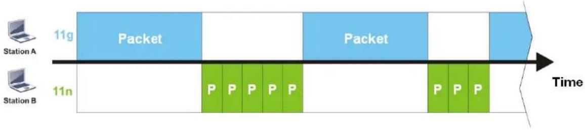
flowchart
graph LR
    A["Station A"] --> B["11g Packet"]
    C["Station B"] --> D["11n"]
    B --> E["Packet"]
    D --> F["P P P P P P"]
    E --> G["Time"]
    F --> G
    G --> H["Packet"]
    H --> I["11g Packet"]
    I --> J["11n"]
It is similar to automatic Bandwidth Limit. The dynamic bandwidth limit of each station depends on instant active station number and airtime assignment. Please note that Airtime Fairness of 2.4GHz and 5GHz are independent. But stations of different SSIDs function together, because they all use the same wireless channel. IN SPECIFIC ENVIRONMENTS, this function can reduce the bad influence of slow wireless devices and improve the overall wireless performance.
Suitable environment:
(1) Many wireless stations.
(2) All stations mainly use download traffic.
(3) The performance bottleneck is wireless connection.
Wireless LAN (2.4GHz) >> Airtime Fairness

text_image
Enable Airtime Fairness Triggering Client Number (2-64) 2 (Default: 2)Note: Please enable or disable this function according to the real situation and user experience. It is NOT suitable for all environments.

Available settings are explained as follows:
| Item | Description |
| Enable Airtime Fairness | Try to assign similar airtime to each wireless station by controlling TX traffic.Airtime Fairness – Click the link to display the following screen of airtime fairness note.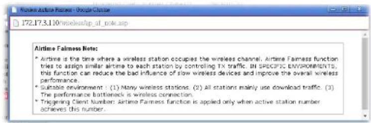 Triggering Client Number –Airtime Fairness function is applied only when active station number achieves this number. Triggering Client Number –Airtime Fairness function is applied only when active station number achieves this number. |
After finishing this web page configuration, please click OK to save the settings.
Note: Airtime Fairness function and Bandwidth Limit function should be mutually exclusive. So their webs have extra actions to ensure these two functions are not enabled simultaneously.
3.9.11 Station Control
Station Control is used to specify the duration for the wireless client to connect and reconnect VigorAP. If such function is not enabled, the wireless client can connect VigorAP until it shuts down.
Such feature is especially useful for free Wi-Fi service. For example, a coffee shop offers free Wi-Fi service for its guests for one hour every day. Then, the connection time can be set as “1 hour” and reconnection time can be set as “1 day”. Thus, the guest can finish his job within one hour and will not occupy the wireless network for a long time.
Note: Up to 300 Wireless Station records are supported by VigorAP.
Wireless LAN (2.4GHz) >> Station Control
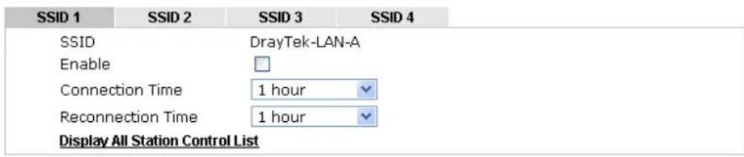
text_image
SSID 1 SSID 2 SSID 3 SSID 4 SSID DrayTek-LAN-A Enable Connection Time 1 hour Reconnection Time 1 hour Display All Station Control ListNote: Once the feature is enabled, the connection time quota will apply to each wireless client (identified by MAC address).

Available settings are explained as follows:
| Item | Description |
| SSID | Display the SSID that the wireless station will use it to connect with Vigor router. |
| Enable | Check the box to enable the station control function. |
| Connection Time / Reconnection Time | Use the drop down list to choose the duration for the wireless client connecting /reconnecting to Vigor router. Or, type the duration manually when you chooseUser defined.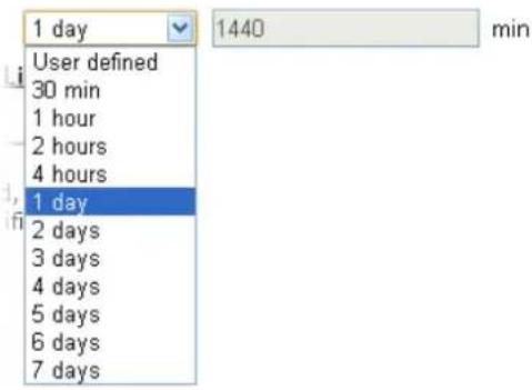 |
| Display All Station Control List | All the wireless stations connecting to Vigor router by using such SSID will be listed on Station Control List. |
After finishing all the settings here, please click OK to save the configuration.
3.9.12 Roaming
The network signal for a single wireless access point might be limited by its coverage range. Therefore, if you want to expand the wireless network in a large exhibition with a quick method, you can install multiple access points with enabling the Roaming feature for each AP to reach the purpose of expanding wireless signals seamlessly.
These access points connecting for each other shall be verified by pre-authentication. This page allows you to enable the roaming feature and the pre-authentication.
Wireless LAN (2.4GHz) >> Roaming
AP-assisted Client Roaming Parameters

text_image
Minimum Basic Rate 1 Mbps Disable RSSI Requirement Strictly Minimum RSSI -73 dBm (42 %) (Default: -73) Minimum RSSI -66 dBm (60 %) (Default: -66) with Adjacent AP RSSI over 5 dBm (Default: 5)Fast Roaming(WPA/802.1x)

text_image
Enable PMK Caching : Cache Period 10 minute(s) (10 ~ 600) (Default: 10) Pre-Authentication
Available settings are explained as follows:
| Item | Description |
| AP-assisted Client Roaming Parameters | When the link rate of wireless station is too low or the signal received by the wireless station is too worse, VigorAP 902 will automatically detect (based on the link rate and RSSI requirement) and cut off the network connection for that wireless station to assist it to connect another Wireless AP to get better signal. Minimum Basic Rate - Check the box to use the drop down list to specify a basic rate (Mbps). When the link rate of the wireless station is below such value, VigorAP 902 will terminate the network connection for that wireless station. Disable RSSI Requirement - If it is selected, VigorAP will not terminate the network connection based on RSSI. Strictly Minimum RSSI - VigorAP uses RSSI (received signal strength indicator) to decide to terminate the network connection of wireless station. When the signal strength is below the value (dBm) set here, VigorAP 902 will terminate the network connection for that wireless station. Minimum RSSI - When the signal strength of the wireless station is below the value (dBm) set here and adjacent AP (must be DrayTek AP and support such feature too) with higher signal strength value (defined in the field of With Adjacent AP RSSI over) is detected by VigorAP 902, VigorAP 902 will terminate the network connection for that wireless station. Later, thewireless station can connect to the adjacent AP (with better RSSI).● With Adjacent AP RSSI over – Specify a value as a threshold. |
| Fast Roaming (WPA/802.1x) | Enable – Check the box to enable fast roaming configuration.PMK Cache Period - Set the expire time of WPA2 PMK (Pairwise master key) cache. PMK Cache manages the list from the BSSIDs in the associated SSID with which it has pre-authenticated. Such feature is available for WPA2/802.1 mode.Pre-Authentication - Enables a station to authenticate to multiple APs for roaming securer and faster. With the pre-authentication procedure defined in IEEE 802.11i specification, the pre-four-way-handshake can reduce handoff delay perceivable by a mobile node. It makes roaming faster and more secure. (Only valid in WPA2)Enable - Enable IEEE 802.1X Pre-Authentication.Disable - Disable IEEE 802.1X Pre-Authentication. |
After finishing this web page configuration, please click OK to save the settings.
3.9.13 Band Steering
Band Steering detects if the wireless clients are capable of 5GHz operation, and steers them to that frequency. It helps to leave 2.4GHz band available for legacy clients, and improves users experience by reducing channel utilization.
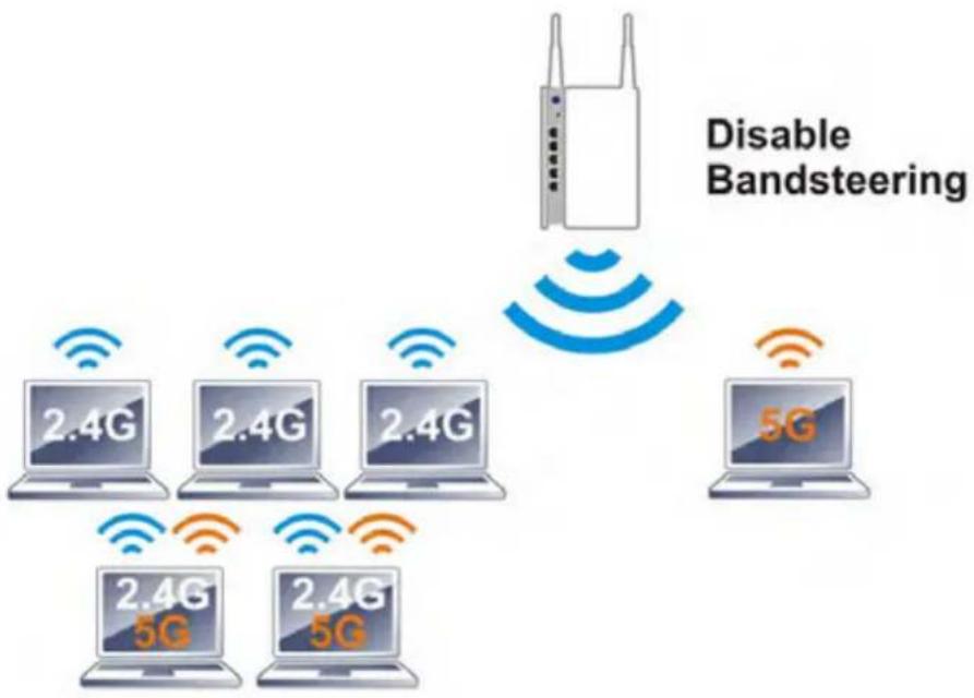
flowchart
graph TD
    A["Disable Bandsteering"] --> B["5G"]
    A --> C["2.4G"]
    A --> D["2.4G"]
    A --> E["2.4G"]
    A --> F["5G"]
    A --> G["2.4G 5G"]
If dual-band is detected, the AP will let the wireless client connect to less congested wireless LAN, such as 5GHz to prevent from network congestion.
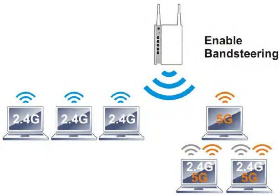
text_image
Enable Bandsteering 2.4G 2.4G 2.4G 5G 2.4G 5G 2.4G 5GNote: To make Band Steering work successfully, SSID and security on 2.4GHz also MUST be broadcasted on 5GHz.
Open Wireless LAN (2.4GHz)>>Band Steering to get the following web page:
Wireless LAN >> Band Steering

text_image
Enable Band Steering Check Time for WLAN Client 5G Capability 15 second(s) (1 ~ 60) (Default: 15)Note: Please setup at least one pair of 2.4GHz and 5GHz Wireless LAN with the same SSID and security.

Available settings are explained as follows:
| Item | Description |
| Enable Band Steering | If it is enabled, VigorAP will detect if the wireless client is capable of dual-band or not within the time limit.Check Time.... – If the wireless station does not have the capability of 5GHz network connection, the system shall wait and check for several seconds (15 seconds, in default) to make the 2.4GHz network connection. Specify the time limit for VigorAP to detect the wireless client. |
After finishing this web page configuration, please click OK to save the settings.
Below shows how Band Steering works.
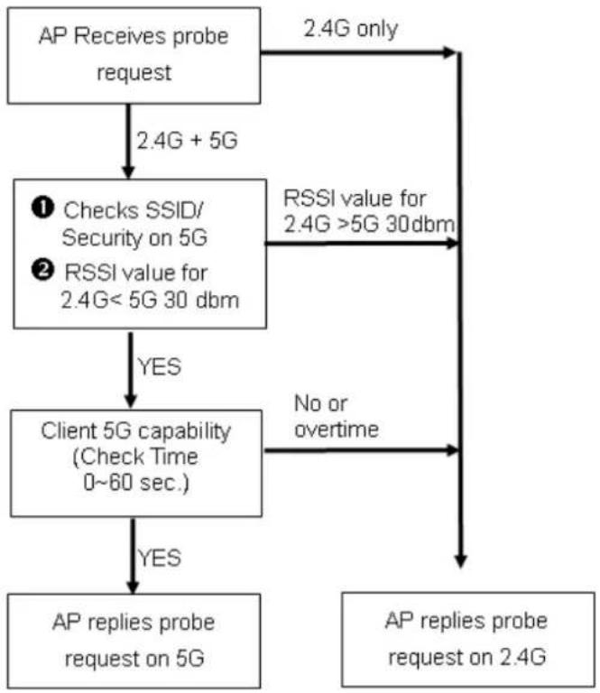
flowchart
graph TD
    A["AP Receives probe request"] -->|2.4G + 5G| B["① Checks SSID/Security on 5G"]
    A -->|2.4G only| C["RSSI value for 2.4G >5G 30 dbm"]
    B -->|YES| D["Client 5G capability (Check Time 0~60 sec.)"]
    B -->|No or overtime| E["AP replies probe request on 2.4G"]
    D -->|YES| F["AP replies probe request on 5G"]
    D -->|No or overtime| E
How to Use Band Steering?
- Open Wireless LAN(2.4GHz)>>Band Steering.
- Check the box of Enable Band Steering and use the default value (15) for check time setting.
Wireless LAN >> Band Steering
Enable Band Steering Check Time for WLAN Client 5G Capability 15 second(s) (1 \~ 60) (Default: 15)
Note: Please setup at least one pair of 2.4GHz and 5GHz Wireless LAN with the same SSID and security.
OK Cancel
- Click OK to save the settings.
- Open Wireless LAN (2.4GHz)>>General Setup and Wireless LAN (5GHz)>>General Setup. Configure SSID as ap902-BandSteering for both pages. Click OK to save the settings.
Wireless LAN (2.4GHz) >> General Setup
General Setting ( IEEE 802.11 )

text_image
Enable Wireless LAN Enable Limit Client (3-64) 64 (default: 64) Mode : Mixed(11b+11g+11n) Hide SSID SSID Isolate VLAN ID Member (0:Untagged) MAC Clone 1 ap902-BandSteering 2 3 4 Hide SSID: Prevent SSID from being scanned. Isolate Member: Wireless clients (stations) with the same SSID cannot access for each other. MAC Clone: Set the MAC address of SSID 1. The MAC addresses of other SSIDs and the Wireless client will also change based on this MAC address. Please notice that the last date of this MAC address must be aSame value for 2.4GHz and 5GHz
Wireless LAN (5GHz) >> General Setup
General Setting ( IEEE 802.11 )
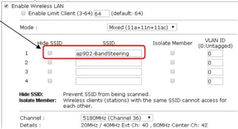
text_image
Enable Wireless LAN Enable Limit Client (3-64) 64 (default: 64) Mode : Mixed (11a+11n+11ac) Hide SSID SSID Isolate Member VLAN ID 1 ap902-BandSteering 0 2 3 4 Hide SSID: Prevent SSID from being scanned. Isolate Member: Wireless clients (stations) with the same SSID cannot access for each other. Channel : 5180MHz (Channel 36) Details : 20MHz / 40MHz Ext Ch: 40 , 80MHz Center Ch: 42- Open Wireless LAN (2.4GHz)>>Security and Wireless LAN (5GHz)>>Security. Configure Security as 12345678 for both pages. Click OK to save the settings.
Wireless LAN (2.4GHz) >> Security Settings
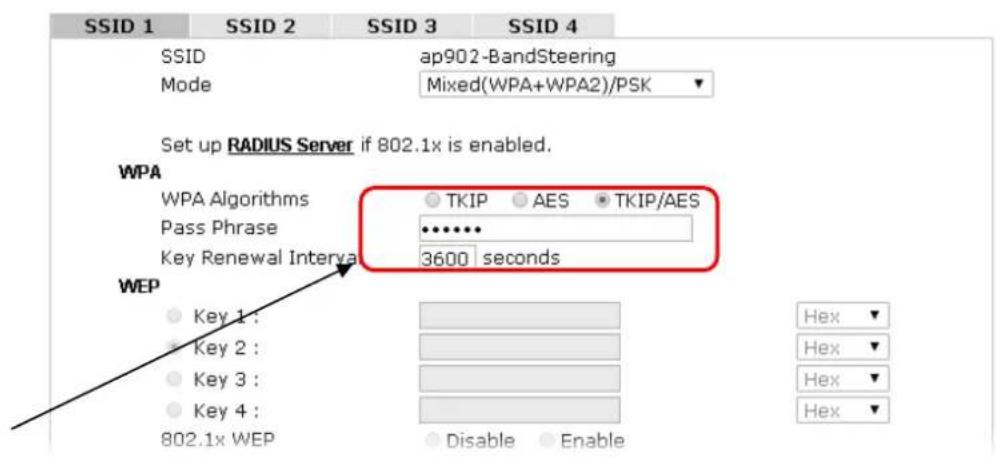
text_image
SSID 1 SSID 2 SSID 3 SSID 4 SSID ap902-BandSteering Mode Mixed(WPA+WPA2)/PSK Set up RADIUS Server if 802.1x is enabled. WPA WPA Algorithms TKIP AES TKIP/AES Pass Phrase •••••• Key Renewal Interval 3600 seconds WEP Key 1: Key 2: Key 3: Key 4: 802.1x WEP Disable Enable Hex Hex Hex HexSame value for 2.4GHz and 5GHz
Wireless LAN (5GHz) >> Security Settings
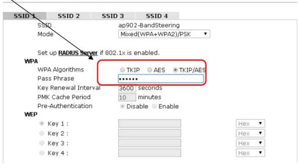
text_image
SSID 1 SSID 2 SSID 3 SSID 4 SSID ap902-BandSteering Mode Mixed(WPA+WPA2)/PSK Set up RADIUS Server if 802.1x is enabled. WPA WPA Algorithms TKIP AES TKIP/AES Pass Phrase ••••••• Key Renewal Interval 3600 seconds PMK Cache Period 10 minutes Pre-Authentication Disable Enable WEP Key 1 : Key 2 : Key 3 : Key 4 : Hex Hex Hex Hex- Now, VigorAP 902 will let the wireless clients connect to less congested wireless LAN, such as 5GHz to prevent from network congestion.
3.9.14 Station List
Station List provides the knowledge of connecting wireless clients now along with its status code.
General
Display general information (e.g., MAC Address, SSID, Auth, Encrypt, TX/RX Rate) for the station.
Wireless LAN (2.4GHz) >> Station List
Station List
| General | Advanced | Control | Neighbor | |||
| Index | MAC Address | Vendor | RSSI | Approx. Distance | SSID | Visit Time |
| 1 | DA:A1:19:E2:65:AD | 5%(-88dBm) | 141.25m | N/A | 0d:0h: | |
| 2 | 00:50:7F:F0:BD:2B | DrayTek | 52%(-69dBm) | 15.85m | N/A | 0d:0h: |
| 3 | 00:50:7F:37:6D:E5 | DrayTek | 47%(-71dBm) | 19.95m | N/A | 0d:0h: |
| 4 | 1C:4B:D6:8B:9C:00 | Azurewav | 18%(-83dBm) | 79.43m | N/A | 0d:1h: |
| 5 | 00:15:AF:A5:24:A0 | Azurewav | 26%(-79dBm) | 50.12m | N/A | 0d:0h: |
| 6 | B0:34:95:22:50:FD | Apple | 47%(-71dBm) | 19.95m | N/A | 0d:0h: |
| 7 | B4:52:7E:D6:68:9D | Sony | 20%(-82dBm) | 70.79m | N/A | 0d:0h: |
| 8 | 00:1F:3C:51:9C:55 | Intel | 39%(-74dBm) | 28.18m | N/A | 0d:1h: |
| Refresh | ||||||
| Add to Access Control :Client's MAC Address : □ : □ : □ : □ : □ : □ | ||||||
Note: 1. Approx. Distance is calculated by actual signal strength of device detected. Inaccuracy might occur based on barrier encountered.
2. Due to the differences in signal strength for different devices, the calculated value of approximate distance also might be different.
3. Trademarks and brand names are the properties of their respective owners.
Add
Available settings are explained as follows:
| Item | Description |
| MAC Address | Display the MAC Address for the connecting client. |
| Hostname | Display the host name of the connecting client. |
| SSID | Display the SSID that the wireless client connects to. |
| Auth | Display the authentication that the wireless client uses for connection with such AP. |
| Encrypt | Display the encryption mode used by the wireless client. |
| Tx Rate/Rx Rate | Display the transmission /receiving rate for packets. |
| Refresh | Click this button to refresh the status of station list. |
| Add to Access Control | Client's MAC Address - For additional security of wireless access, the Access Control facility allows you to restrict the network access right by controlling the wireless LAN MAC address of client. Only the valid MAC address that has been configured can access the wireless LAN interface. |
| Add | Click this button to add current typed MAC address into Access Control. |
Advanced
Display more information (e.g., AID, PSM, WMM, RSSI PhMd, BW, MCS, Rate) for the station.
Control
Display connection and reconnection time of the wireless stations.
Neighbor
Display more information for the neighboring wireless stations.
3.10 Wireless LAN (5GHz) Settings for AP Mode
The AP mode allows wireless clients to connect to access point and exchange data with the devices connected to the wired network.
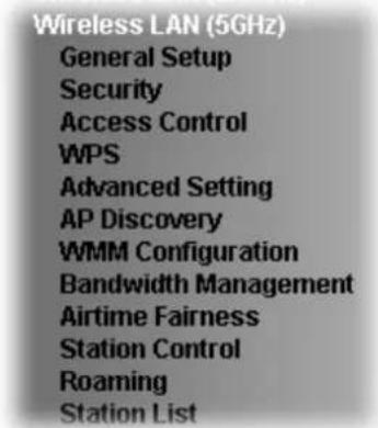
text_image
Wireless LAN (5GHz) General Setup Security Access Control WPS Advanced Setting AP Discovery WMM Configuration Bandwidth Management Airtime Fairness Station Control Roaming Station List3.10.1 General Setup
By clicking the General Setup, a new web page will appear so that you could configure the general settings for wireless connection such as specifying SSID, selecting the wireless channel, isolate LAN connection and so on.
Wireless LAN (5GHz) >> General Setup
General Setting ( IEEE 802.11 )
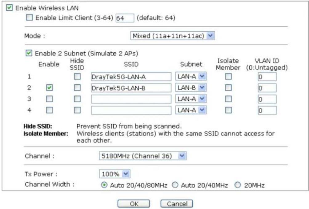
text_image
Enable Wireless LAN Enable Limit Client (3-64) 64 (default: 64) Mode : Mixed (11a+11n+11ac) Enable 2 Subnet (Simulate 2 APs) Enable Hide SSID SSID Subnet Isolate Member VLAN ID (0:Untagged) 1 DrayTek5G-LAN-A LAN-A 0 2 DrayTek5G-LAN-B LAN-B 0 3 LAN-A 0 4 LAN-A 0 Hide SSID: Prevent SSID from being scanned. Isolate Member: Wireless clients (stations) with the same SSID cannot access for each other. Channel : 5180MHz (Channel 36) Tx Power : 100% Channel Width : Auto 20/40/80MHz Auto 20/40MHz 20MHz OK CancelAvailable settings are explained as follows:
| Item | Description |
| Enable Wireless LAN | Check the box to enable wireless function. |
| Enable Limit Client | Check the box to set the maximum number of wireless stations which try to connect Internet through VigorAP. The number youcan set is from 3 to 64. |
| Mode | At present, VigorAP 902 can be connected by 11a only, 11n only (5G), Mixed (11a+11n) and Mixed (11a+11n+ac) stations simultaneously. Simply choose Mixed (11a+11n+ac) mode.Mixed (11a+11n)11a Only11n Only (5G)Mixed (11a+11n)Mixed (11a+11n+11ac) |
| Enable 2 Subnet(Simulate 2 APs) | Check the box to enable the function for two independent subnets. Once you enable this function, LAN-A and LAN-B would be independent. Next, you can connect one router in LAN-A, and another router in LAN-B. Such mechanism can make you feeling that you have two independent AP/subnet functions in one VigorAP 902.If you disable this function, LAN-A and LAN-B ports are in the same domain. You could only connect one router (no matter connecting to LAN-A or LAN-B) in this environment. |
| Hide SSID | Check it to prevent from wireless sniffing and make it harder for unauthorized clients or STAs to join your wireless LAN.Depending on the wireless utility, the user may only see the information except SSID or just cannot see any thing about VigorAP 902 while site surveying. The system allows you to set four sets of SSID for different usage. |
| SSID | Set a name for VigorAP 902 to be identified. Default settings are Draytek_5G-LANA and Draytek_5G-LANB. When Enable 2 Subnet is enabled, you can specify subnet interface (LAN-A or LAN-B) for each SSID by using the drop down menu. |
| Subnet | Choose LAN-A or LAN-B for each SSID. If you choose LAN-A, the wireless clients connecting to this SSID could only communicate with LAN-A. |
| Isolate Member | Check this box to make the wireless clients (stations) with the same SSID not accessing for each other. |
| VLAN ID | Type the value for such SSID. Packets transferred from such SSID to LAN will be tagged with the number.If your network uses VLANs, you can assign the SSID to a VLAN on your network. Client devices that associate using the SSID are grouped into this VLAN. The VLAN ID range is from 3 to 4095. The VLAN ID is 0 by default, it means disabling the VLAN function for the SSID. |
| Channel | Means the channel of frequency of the wireless LAN. The default channel is 36. You may switch channel if the selected channel is under serious interference. |
| Extension Channel | With 802.11n, there is one option to double the bandwidth per channel. The available extension channel options will be varied according to the Channel selected above. |
| Channel Width | Auto 20/40 MHZ– the AP will use 20Mhz or 40Mhz for data transmission and receiving according to the station capability. Such channel can increase the performance for data transmission.20 MHZ- the AP will use 20Mhz for data transmission and receiving between the AP and the stations.40 MHZ- the AP will use 40Mhz for data transmission and receiving between the AP and the stations. |
After finishing this web page configuration, please click OK to save the settings.
3.10.2 Security
This page allows you to set security with different modes for SSID 1, 2, 3 and 4 respectively. After configuring the correct settings, please click OK to save and invoke it.
By clicking the Security Settings, a new web page will appear so that you could configure the settings.
Wireless LAN (5GHz) >> Security Settings
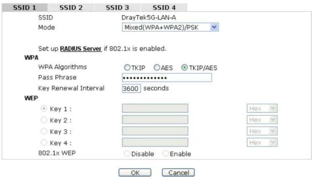
text_image
SSID 1 SSID 2 SSID 3 SSID 4 SSID DrayTek5G-LAN-A Mode Mixed(WPA+WPA2)/PSK Set up RADIUS Server if 802.1x is enabled. WPA WPA Algorithms ○TKIP ○AES ●TKIP/AES Pass Phrase ••••••••••• Key Renewal Interval 3600 seconds WEP ● Key 1 : ○ Key 2 : ○ Key 3 : ○ Key 4 : 802.1x WEP ○Disable ○Enable Hex Hex Hex Hex OK CancelAvailable settings are explained as follows:
| Item | Description |
| Mode | There are several modes provided for you to choose. |
| Disable | |
| Disable | |
| WEP | |
| WPA/PSK | |
| WPA2/PSK | |
| Mixed(WPA+WPA2)/PSK | |
| WEP/802.1x | |
| WPA/802.1x | |
| WPA2/802.1x | |
| Mixed(WPA+WPA2)/802.1x | |
| Disable - The encryption mechanism is turned off. | |
| WEP - Accepts only WEP clients and the encryption key should be entered in WEP Key.WPA/PSK or WPA2/PSK or Mixed (WPA+WPA2)/PSK - Accepts only WPA clients and the encryption key should be entered in PSK. The WPA encrypts each frame transmitted from the radio using the key, which either PSK (Pre-Shared Key) entered manually in this field below or automatically negotiated via 802.1x authentication.WEP/802.1x - The built-in RADIUS client feature enables VigorAP 902 to assist the remote dial-in user or a wireless station and the RADIUS server in performing mutual authentication. It enables centralized remote access authentication for network management.The WPA encrypts each frame transmitted from the radio using the key, which either PSK (Pre-Shared Key) entered manually in this field below or automatically negotiated via 802.1x authentication. Select WPA, WPA2 or Auto as WPA mode.WPA/802.1x - The WPA encrypts each frame transmitted from the radio using the key, which either PSK (Pre-Shared Key) entered manually in this field below or automatically negotiated via 802.1x authentication.WPA2/802.1x - The WPA encrypts each frame transmitted from the radio using the key, which either PSK (Pre-Shared Key) entered manually in this field below or automatically negotiated via 802.1x authentication. | |
| WPA Algorithms | Select TKIP, AES or TKIP/AES as the algorithm for WPA. Such feature is available for WPA2/802.1x, WPA/802.1x, WPA/PSK or WPA2/PSK or Mixed (WPA+WPA2)/PSK mode. |
| Pass Phrase | Either 8~63 ASCII characters, such as 012345678..(or 64 Hexadecimal digits leading by 0x, such as "0x321253abcde..."). Such feature is available for WPA/PSK or WPA2/PSK or Mixed (WPA+WPA2)/PSK mode. |
| Key Renewal Interval | WPA uses shared key for authentication to the network. However, normal network operations use a different encryption key that is randomly generated. This randomly generated key that is periodically replaced. Enter the renewal security time (seconds) in the column. Smaller interval leads to greater security but lower performance. Default is 3600 seconds. Set 0 to disable re-key. Such feature is available for WPA2/802.1,WPA/802.1x, WPA/PSK or WPA2/PSK or Mixed (WPA+WPA2)/PSK mode. |
| PMK Cache Period | Set the expire time of WPA2 PMK (Pairwise master key) cache. PMK Cache manages the list from the BSSIDs in the associated SSID with which it has pre-authenticated. Such feature is available for WPA2/802.1 mode. |
| Pre-Authentication | Enables a station to authenticate to multiple APs for roaming securer and faster. With the pre-authentication procedure defined in IEEE 802.1i specification, thepre-four-way-handshake can reduce handoff delay perceivable by a mobile node. It makes roaming faster and more secure. (Only valid in WPA2)Enable - Enable IEEE 802.1X Pre-Authentication.Disable - Disable IEEE 802.1X Pre-Authentication. |
| Key 1 – Key 4 | Four keys can be entered here, but only one key can be selected at a time. The format of WEP Key is restricted to 5 ASCII characters or 10 hexadecimal values in 64-bit encryption level, or restricted to 13 ASCII characters or 26 hexadecimal values in 128-bit encryption level. The allowed content is the ASCII characters from 33(!) to 126(~) except '#' and ','. Such feature is available for WEP mode.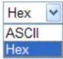 |
| 802.1x WEP | Disable - Disable the WEP Encryption. Data sent to the AP will not be encrypted.Enable - Enable the WEP Encryption.Such feature is available for WEP/802.1x mode. |
Click the link of RADIUS Server to access into the following page for more settings.
RADIUS Server
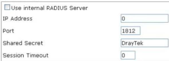
text_image
Use internal RADIUS Server IP Address 0 Port 1812 Shared Secret DrayTek Session Timeout 0
Available settings are explained as follows:
| Item | Description |
| Use internal RADIUS Server | There is a RADIUS server built in VigorAP 902 which is used to authenticate the wireless client connecting to the access point. Check this box to use the internal RADIUS server for wireless security.Besides, if you want to use the external RADIUS server for authentication, do not check this box.Please refer to the section,3.12 RADIUS Serverto configure settings for internal server of VigorAP 902. |
| IP Address | Enter the IP address of external RADIUS server. |
| Port | The UDP port number that the external RADIUS server is using. The default value is 1812, based on RFC 2138. |
| Shared Secret | The external RADIUS server and client share a secret that is used to authenticate the messages sent between them. Both sides must be configured to use the same shared secret. |
| Session Timeout | Set the maximum time of service provided before re-authentication. Set to zero to perform another authentication immediately after the first authentication has successfully completed. (The unit is second.) |
After finishing this web page configuration, please click OK to save the settings.
3.10.3 Access Control
For additional security of wireless access, the Access Control facility allows you to restrict the network access right by controlling the wireless LAN MAC address of client. Only the valid MAC address that has been configured can access the wireless LAN interface. By clicking the Access Control, a new web page will appear, as depicted below, so that you could edit the clients' MAC addresses to control their access rights (deny or allow).
Wireless LAN (5GHz) >> Access Control
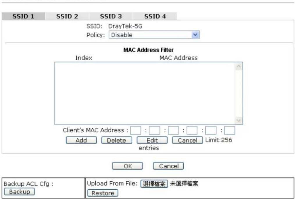
text_image
SSID 1 SSID 2 SSID 3 SSID 4 SSID: DrayTek-5G Policy: Disable MAC Address Filter Index MAC Address Client's MAC Address : □ : □ : □ : □ : □ : □ : □ Add Delete Edit Cancel Limit:256 entries OK Cancel Backup ACL Cfg : Backup Upload From File: 選擇檔案 未選擇檔案 RestoreAvailable settings are explained as follows:
| Item | Description |
| Policy | Select to enable any one of the following policy or disable the policy. ChooseActivate MAC address filterto type in the MAC addresses for other clients in the network manually.ChooseBlocked MAC address filter,so that all of the devices with the MAC addresses listed on the MAC Address Filter table will be blocked and cannot access into VigorAP 902.Activate MAC address filterDisableActivate MAC address filterBlocked MAC address filter |
| MAC Address Filter | Display all MAC addresses that are edited before. |
| Client's MAC Address | Manually enter the MAC address of wireless client. |
| Add | Add a new MAC address into the list. |
| Delete | Delete the selected MAC address in the list. |
| Edit | Edit the selected MAC address in the list. |
| Cancel | Give up the access control set up. |
| Backup | Click it to store the settings (MAC addresses on MAC Address Filter table) on this page as a file. |
| Restore | Click it to restore the settings (MAC addresses on MAC Address Filter table) from an existed file. |
After finishing this web page configuration, please click OK to save the settings.
3.10.4 WPS
Open Wireless LAN>>WPS to configure the corresponding settings.
Wireless LAN (5GHz) >> WPS (Wi-Fi Protected Setup)
Enable WPS
Wi-Fi Protected Setup Information
| WPS Configured | Yes |
| WPS SSID | Draytek_5G-LANA |
| WPS Auth Mode | Mixed(WPA+WPA2)/PSK |
| WPS Encryp Type | TKIP/AES |
Device Configure
| Configure via Push Button | Start PBC | |
| Configure via Client PinCode | Start PIN |
Status: Idle
Note: WPS can help your wireless client automatically connect to the Access point.
: WPS is Disabled.
Q: WPS is Enabled.
: Waiting for WPS requests from wireless clients.
Available settings are explained as follows:
| Item | Description |
| Enable WPS | Check this box to enable WPS setting. |
| WPS Configured | Display related system information for WPS. If the wireless security (encryption) function of VigorAP 902 is properly configured, you can see ‘Yes’ message here. |
| WPS SSID | Display current selected SSID. |
| WPS Auth Mode | Display current authentication mode of the VigorAP 902. Only WPA2/PSK and WPA/PSK support WPS. |
| WPS Encryp Type | Display encryption mode (None, WEP, TKIP, AES, etc.) of VigorAP 902. |
| Configure via Push | Click Start PBC to invoke Push-Button style WPS setup |
| Button | procedure. VigorAP 902 will wait for WPS requests from wireless clients about two minutes. Both ACT and 5G WLAN LEDs on VigorAP 902 will blink quickly when WPS is in progress. It will return to normal condition after two minutes. (You need to setup WPS within two minutes) |
| Configure via Client PinCode | Type the PIN code specified in wireless client you wish to connect, and click Start PIN button. Both ACT and 5G WLAN LEDs on VigorAP 902 will blink quickly when WPS is in progress. It will return to normal condition after two minutes. (You need to setup WPS within two minutes). |
3.10.5 Advanced Setting
This page is to determine which algorithm will be selected for wireless transmission rate.
Wireless LAN (2.4GHz) >> Advanced Setting
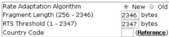
text_image
Rate Adaptation Algorithm Fragment Length (256 - 2346) RTS Threshold (1 - 2347) Country Code New Old 2346 bytes 2347 bytes (Reference)
Available settings are explained as follows:
| Item | Description |
| Rate Adaptation Algorithm | Wireless transmission rate is adapted dynamically. Usually, performance of “new” algorithm is better than “old”. |
| Fragment Length | Set the Fragment threshold of wireless radio. Do not modify default value if you don’t know what it is, default value is 2346. |
| RTS Threshold | Minimize the collision (unit is bytes) between hidden stations to improve wireless performance.Set the RTS threshold of wireless radio. Do not modify default value if you don’t know what it is, default value is 2347. |
| Country Code | VigorAP broadcasts country codes by following the 802.11d standard. However, some wireless stations will detect / scan the country code to prevent conflict occurred. If conflict is detected, wireless station will be warned and is unable to make network connection. Therefore, changing the country code to ensure successful network connection will be necessary for some clients. |
3.10.6 AP Discovery
VigorAP 902 can scan all regulatory channels and find working APs in the neighborhood. Based on the scanning result, users will know which channel is clean for usage. Also, it can be used to facilitate finding an AP for a WDS link. Notice that during the scanning process (about 5 seconds), no client is allowed to connect to Vigor.
This page is used to scan the existence of the APs on the wireless LAN. Please click Scan to discover all the connected APs.
Wireless LAN (5G) >> Access Point Discovery
Access Point List
| SSID | BSSID | RSSI | Channel | Encryption | Authentication |
Scan
Note: During the scanning process (about 5 seconds), no station is allowed to connect with the AP.
Each item is explained as follows:
| Item | Description |
| SSID | Display the SSID of the AP scanned by VigorAP 902. |
| BSSID | Display the MAC address of the AP scanned by VigorAP 902. |
| RSSI | Display the signal strength of the access point. RSSI is the abbreviation of Received Signal Strength Indication. |
| Channel | Display the wireless channel used for the AP that is scanned by VigorAP 902. |
| Encryption | Display the encryption mode for the scanned AP. |
| Authentication | Display the authentication type that the scanned AP applied. |
| Scan | It is used to discover all the connected AP. The results will be shown on the box above this button |
3.10.7 WMM Configuration
WMM is an abbreviation of Wi-Fi Multimedia. It defines the priority levels for four access categories derived from 802.1d (prioritization tabs). The categories are designed with specific types of traffic, voice, video, best effort and low priority data. There are four accessing categories - AC_BE , AC_BK, AC_VI and AC_VO for WMM.
Wireless LAN (5GHz) >> WMM Configuration
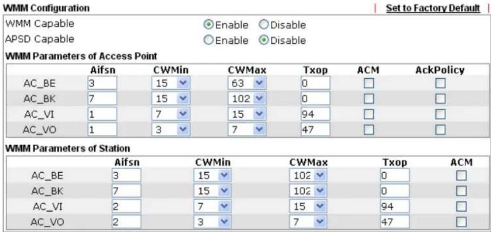
text_image
WMM Configuration Set to Factory Default WMM Capable ● Enable ○ Disable APSD Capable ○ Enable ● Disable WMM Parameters of Access Point Aifsn CWMin CWMax Txop ACM AckPolicy AC_BE 3 15 63 0 □ □ AC_BK 7 15 102 0 □ □ AC_VI 1 7 15 94 □ □ AC_VO 1 3 7 47 □ □ WMM Parameters of Station Aifsn CWMin CWMax Txop ACM AC_BE 3 15 102 0 □ AC_BK 7 15 102 0 □ AC_VI 2 7 15 94 □ AC_VO 2 3 7 47 □
Available settings are explained as follows:
| Item | Description |
| WMM Capable | To apply WMM parameters for wireless data transmission, please click the Enable radio button. |
| Aifsn | It controls how long the client waits for each data transmission. Please specify the value ranging from 1 to 15. Such parameter will influence the time delay for WMM accessing categories. For the service of voice or video image, please set small value for AC_VI and AC_VO categories For the service of e-mail or web browsing, please set large value for AC_BE and AC_BK categories. |
| CWMin/CWMax | CWMin means contention Window-Min and CWMax means contention Window-Max. Please specify the value ranging from 1 to 15. Be aware that CWMax value must be greater than CWMin or equals to CWMin value. Both values will influence the time delay for WMM accessing categories. The difference between AC_VI and AC_VO categories must be smaller; however, the difference between AC_BE and AC_BK categories must be greater. |
| Txop | It means transmission opportunity. For WMM categories of AC_VI and AC_VO that need higher priorities in data transmission, please set greater value for them to get highest transmission opportunity. Specify the value ranging from 0 to 65535. |
| ACM | It is an abbreviation of Admission control Mandatory. It canrestrict stations from using specific category class if it is checked.Note:VigorAP 902 provides standard WMM configuration in the web page. If you want to modify the parameters, please refer to the Wi-Fi WMM standard specification. |
| AckPolicy | “Uncheck” (default value) the box means the AP will answer the response request while transmitting WMM packets through wireless connection. It can assure that the peer must receive the WMM packets.“Check” the box means the AP will not answer any response request for the transmitting packets. It will have better performance with lower reliability. |
After finishing this web page configuration, please click OK to save the settings.
3.10.8 Bandwidth Management
The downstream or upstream from FTP, HTTP or some P2P applications will occupy large of bandwidth and affect the applications for other programs. Please use Bandwidth Management to make the bandwidth usage more efficient.
Wireless LAN (5GHz) >> Bandwidth Management
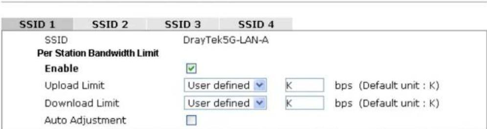
text_image
SSID 1 SSID 2 SSID 3 SSID 4 SSID DrayTek5G-LAN-A Per Station Bandwidth Limit Enable ✓ Upload Limit User defined ✓ K bps (Default unit : K) Download Limit User defined ✓ K bps (Default unit : K) Auto Adjustment □Note: 1. Download : Traffic going to any station. Upload : Traffic being sent from a wireless station. 2. Allow auto adjustment could make the best utilization of available bandwidth.

Available settings are explained as follows:
| Item | Description |
| SSID | Display the specific SSID name. |
| Enable | Check this box to enable the bandwidth management for clients. |
| Upload Limit | Define the maximum speed of the data uploading which will be used for the wireless stations connecting to VigorAP with the same SSID.Use the drop down list to choose the rate. If you choose User defined, you have to specify the rate manually. |
| Download Limit | Define the maximum speed of the data downloading which will be used for the wireless station connecting to VigorAP with the same SSID.Use the drop down list to choose the rate. If you choose User defined, you have to specify the rate manually. |
| Auto Adjustment | Check this box to have the bandwidth limit determined by the |
After finishing this web page configuration, please click OK to save the settings.
3.10.9 Airtime Fairness
Airtime fairness is essential in wireless networks that must support critical enterprise applications.
Most of the applications are either symmetric or require more downlink than uplink capacity; telephony and email send the same amount of data in each direction, while video streaming and web surfing involve more traffic sent from access points to clients than the other way around. This is essential for ensuring predictable performance and quality-of-service, as well as allowing 802.11n and legacy clients to coexist on the same network. Without airtime fairness, offices using mixed mode networks risk having legacy clients slow down the entire network or letting the fastest client(s) crowd out other users.
With airtime fairness, every client at a given quality-of-service level has equal access to the network's airtime.
After finishing this web page configuration, please click OK to save the settings.
The wireless channel can be accessed by only one wireless station at the same time.
The principle behind the IEEE802.11 channel access mechanisms is that each station has equal probability to access the channel. When wireless stations have similar data rate, this principle leads to a fair result. In this case, stations get similar channel access time which is called airtime.
However, when stations have various data rate (e.g., 11g, 11n), the result is not fair. The slow stations (11g) work in their slow data rate and occupy too much airtime, whereas the fast stations (11n) become much slower.
Take the following figure as an example, both Station A(11g) and Station B(11n) transmit data packets through VigorAP 902. Although they have equal probability to access the wireless channel, Station B(11n) gets only a little airtime and waits too much because Station A(11g) spends longer time to send one packet. In other words, Station B(fast rate) is obstructed by Station A(slow rate).
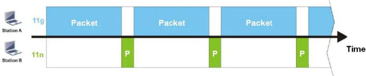
flowchart
graph LR
    A["Station A"] -->|11g| B["Packet"]
    C["Station B"] -->|11n| D["P"]
    B --> E["Packet"]
    E --> F["P"]
    F --> G["Packet"]
    G --> H["P"]
    H --> I["Time"]
To improve this problem, Airtime Fairness is added for VigorAP 902. Airtime Fairness function tries to assign similar airtime to each station (A/B) by controlling TX traffic. In the following figure, Station B(11n) has higher probability to send data packets than Station A(11g). By this way, Station B(fast rate) gets fair airtime and it's speed is not limited by Station A(slow rate).
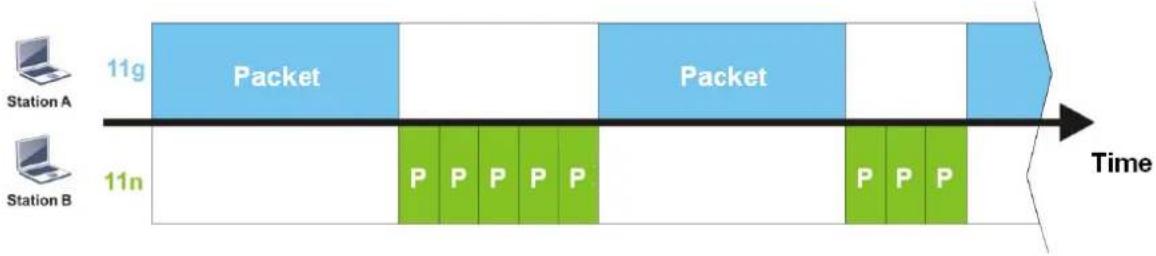
flowchart
graph LR
    A["Station A"] --> B["11g Packet"]
    C["Station B"] --> D["11n P P P P P"]
    B --> E["Time"]
    D --> F["Time"]
    E --> G["Packet"]
    F --> H["Packet"]
It is similar to automatic Bandwidth Limit. The dynamic bandwidth limit of each station depends on instant active station number and airtime assignment. Please note that Airtime Fairness of 2.4GHz and 5GHz are independent. But stations of different SSIDs function together, because they all use the same wireless channel. IN SPECIFIC ENVIRONMENTS, this function can reduce the bad influence of slow wireless devices and improve the overall wireless performance.
Suitable environment:
(1) Many wireless stations.
(2) All stations mainly use download traffic.
(3) The performance bottleneck is wireless connection.
Wireless LAN (5GHz) >> Airtime Fairness

text_image
Enable Airtime Fairness Triggering Client Number (2-64) 2 (default: 2)Note: Please enable or disable this function according to the real situation and user experience. It is NOT suitable for all environments.

Available settings are explained as follows:
| Item | Description |
| Enable Airtime Fairness | Try to assign similar airtime to each wireless station by controlling TX traffic.Airtime Fairness – Click the link to display the following screen of airtime fairness note.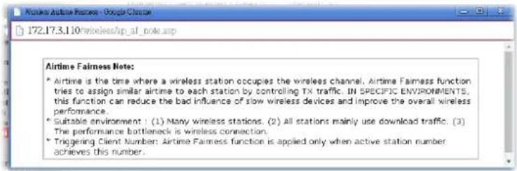 Triggering Client Number –Airtime Fairness function is applied only when active station number achieves this number. Triggering Client Number –Airtime Fairness function is applied only when active station number achieves this number. |
After finishing this web page configuration, please click OK to save the settings.
Note: Airtime Fairness function and Bandwidth Limit function should be mutually exclusive. So their webs have extra actions to ensure these two functions are not enabled simultaneously.
3.10.10 Station Control
Station Control is used to specify the duration for the wireless client to connect and reconnect VigorAP. If such function is not enabled, the wireless client can connect VigorAP until it shuts down.
Such feature is especially useful for free Wi-Fi service. For example, a coffee shop offers free Wi-Fi service for its guests for one hour every day. Then, the connection time can be set as “1 hour” and reconnection time can be set as “1 day”. Thus, the guest can finish his job within one hour and will not occupy the wireless network for a long time.
Note: Up to 300 Wireless Station records are supported by VigorAP.
Wireless LAN (5GHz) >> Station Control
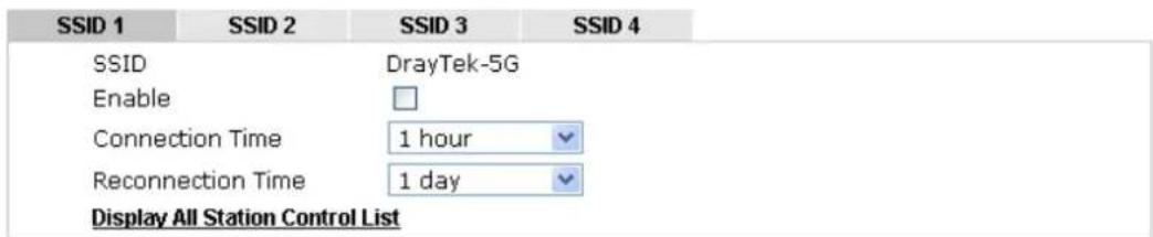
text_image
SSID 1 SSID 2 SSID 3 SSID 4 SSID DrayTek-5G Enable Connection Time 1 hour Reconnection Time 1 day Display All Station Control ListNote: Once the feature is enabled, the connection time quota will apply to each wireless client (identified by MAC address).

Available settings are explained as follows:
| Item | Description |
| SSID | Display the SSID that the wireless station will use it to connect with Vigor router. |
| Enable | Check the box to enable the station control function. |
| Connection Time / Reconnection Time | Use the drop down list to choose the duration for the wireless client connecting /reconnecting to Vigor router. Or, type the duration manually when you chooseUser defined.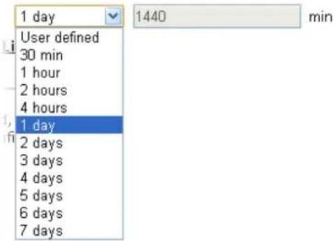 |
| Display All Station Control List | All the wireless stations connecting to Vigor router by using such SSID will be listed on Station Control List. |
After finishing all the settings here, please click OK to save the configuration.
3.10.11 Roaming
The network signal for a single wireless access point might be limited by its coverage range. Therefore, if you want to expand the wireless network in a large exhibition with a quick method, you can install multiple access points with enabling the Roaming feature for each AP to reach the purpose of expanding wireless signals seamlessly.
These access points connecting for each other shall be verified by pre-authentication. This page allows you to enable the roaming feature and the pre-authentication.
Wireless LAN (5GHz) >> Roaming
AP-assisted Client Roaming Parameters
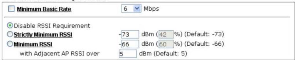
text_image
Minimum Basic Rate 6 Mbps Disable RSSI Requirement Strictly Minimum RSSI -73 dBm (42 %) (Default: -73) Minimum RSSI -66 dBm (60 %) (Default: -66) with Adjacent AP RSSI over 5 dBm (Default: 5)Fast Roaming(WPA/802.1x)

text_image
Enable PMK Caching : Cache Period 10 minute(s) (10 ~ 600) (Default: 10) Pre-Authentication OK CancelAvailable settings are explained as follows:
| Item | Description |
| AP-assisted Client Roaming Parameters | When the link rate of wireless station is too low or the signal received by the wireless station is too worse, VigorAP 902 will automatically detect (based on the link rate and RSSI requirement) and cut off the network connection for that wireless station to assist it to connect another Wireless AP to get better signal. Minimum Basic Rate - Check the box to use the drop down list to specify a basic rate (Mbps). When the link rate of the wireless station is below such value, VigorAP 902 will terminate the network connection for that wireless station. Disable RSSI Requirement - If it is selected, VigorAP will not terminate the network connection based on RSSI. Strictly Minimum RSSI - VigorAP uses RSSI (received signal strength indicator) to decide to terminate the network connection of wireless station. When the signal strength is below the value (dBm) set here, VigorAP 902 will terminate the network connection for that wireless station. Minimum RSSI - When the signal strength of the wireless station is below the value (dBm) set here and adjacent AP (must be DrayTek AP and support such feature too) with higher signal strength value (defined in the field of With Adjacent AP RSSI over) is detected by VigorAP 902, VigorAP 902 will terminatethe network connection for that wireless station. Later, the wireless station can connect to the adjacent AP (with better RSSI).● With Adjacent AP RSSI over – Specify a value as a threshold. |
| Fast Roaming (WPA/802.1x) | Enable – Check the box to enable fast roaming configuration.PMK Cache Period - Set the expire time of WPA2 PMK (Pairwise master key) cache. PMK Cache manages the list from the BSSIDs in the associated SSID with which it has pre-authenticated. Such feature is available for WPA2/802.1 mode.Pre-Authentication - Enables a station to authenticate to multiple APs for roaming securer and faster. With the pre-authentication procedure defined in IEEE 802.11i specification, the pre-four-way-handshake can reduce handoff delay perceivable by a mobile node. It makes roaming faster and more secure. (Only valid in WPA2)Enable - Enable IEEE 802.1X Pre-Authentication.Disable - Disable IEEE 802.1X Pre-Authentication. |
After finishing this web page configuration, please click OK to save the settings.
3.10.12 Station List
Station List provides the knowledge Station List of connecting wireless clients now along with its status code.
General
Display general information (e.g., MAC Address, SSID, Auth, Encrypt, TX/RX Rate) for the station.
Wireless LAN (5GHz) >> Station List
Station List
| General | Advanced | Control | Neighbor | ||||
| Index | MAC Address | Vendor | RSSI | Approx. Distance | SSID | Visit Time | |
| 1 | 80:00:0B:04:CE:5A | Intel | 10%(-86dBm) | 112.20m | N/A | 0d:0h:40m | |
| 2 | DA:A1:19:4B:73:65 | 13%(-85dBm) | 100.00m | N/A | 0d:0h:0m: | ||
| 3 | 00:50:7F:F0:BD:2B | DrayTek | 31%(-77dBm) | 39.81m | N/A | 0d:0h:38m | |
| 4 | DA:A1:19:8F:ED:6B | 10%(-86dBm) | 112.20m | N/A | 0d:0h:0m: | ||
| 5 | 00:1F:3C:51:9C:55 | Intel | 15%(-84dBm) | 89.13m | N/A | 0d:0h:39m | |
| 6 | 00:1D:AA:7E:87:BA | DrayTek | 10%(-86dBm) | 112.20m | N/A | 0d:0h:0m: | |
| Refresh | |||||||
| Add to Access Control :Client's MAC Address : □ : □ : □ : □ : □ : □ | |||||||
Note: 1. Approx. Distance is calculated by actual signal strength of device detected. Inaccuracy might occur based on barrier encountered.
2. Due to the differences in signal strength for different devices, the calculated value of approximate distance also might be different.
Add
Available settings are explained as follows:
| Item | Description |
| MAC Address | Display the MAC Address for the connecting client. |
| Hostname | Display the host name of the connecting client. |
| SSID | Display the SSID that the wireless client connects to. |
| Auth | Display the authentication that the wireless client uses for connection with such AP. |
| Encrypt | Display the encryption mode used by the wireless client. |
| Tx Rate/Rx Rate | Display the transmission /receiving rate for packets. |
| Refresh | Click this button to refresh the status of station list. |
| Add to Access Control | Client's MAC Address - For additional security of wireless access, the Access Control facility allows you to restrict the network access right by controlling the wireless LAN MAC address of client. Only the valid MAC address that has been configured can access the wireless LAN interface. |
| Add | Click this button to add current typed MAC address into Access Control. |
Advanced
Display more information (e.g., AID, PSM, WMM, RSSI PhMd, BW, MCS, Rate) for the station.
Advanced
Display more information (e.g., AID, PSM, WMM, RSSI PhMd, BW, MCS, Rate) for the station.
Control
Display connection and reconnection time of the wireless stations.
Neighbor
Display more information for the neighboring wireless stations.
3.11 Wireless LAN (5GHz) Settings for Universal Repeater Mode
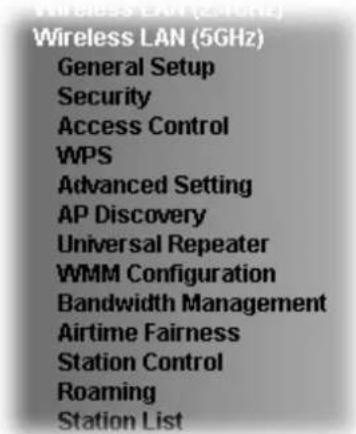
text_image
Wireless LAN (5GHz) General Setup Security Access Control WPS Advanced Setting AP Discovery Universal Repeater WMM Configuration Bandwidth Management Airtime Fairness Station Control Roaming Station List3.11.1 General Setup
By clicking the General Setup, a new web page will appear so that you could configure the SSID and the wireless channel.
Please refer to the following figure for more information.
Wireless LAN (5GHz) >> General Setup
General Setting ( IEEE 802.11 )
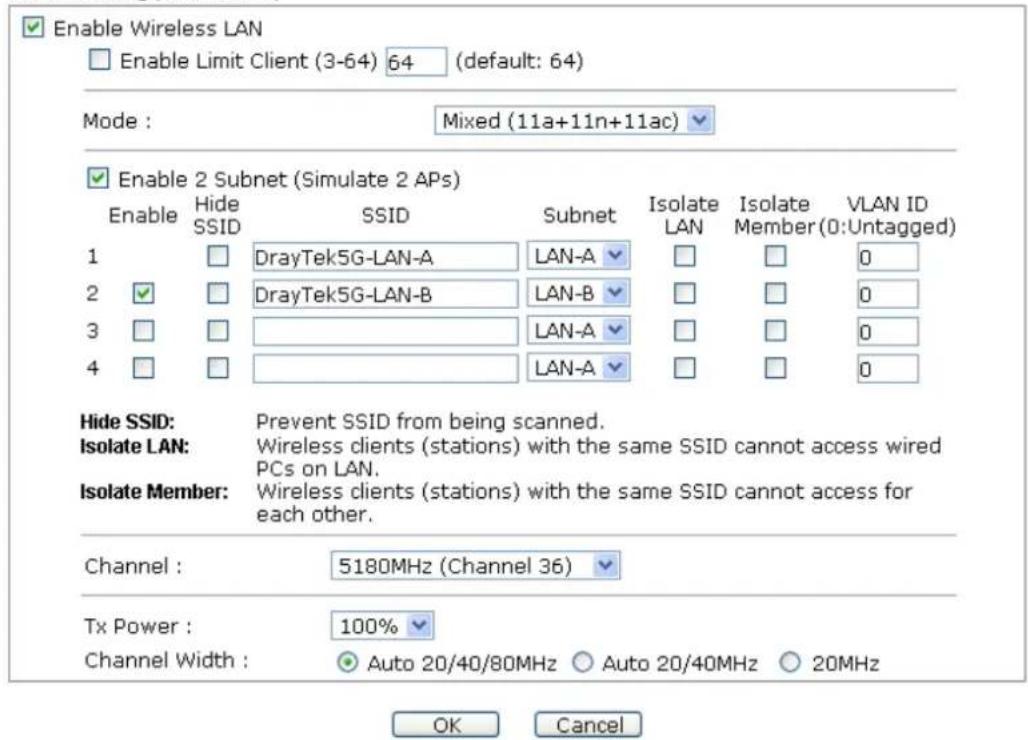
text_image
Enable Wireless LAN Enable Limit Client (3-64) 64 (default: 64) Mode : Mixed (11a+11n+11ac) Enable 2 Subnet (Simulate 2 APs) Enable Hide SSID SSID Subnet Isolate LAN Isolate VLAN ID 1 DrayTek5G-LAN-A LAN-A 0 2 DrayTek5G-LAN-B LAN-B 0 3 LAN-A 0 4 LAN-A 0 Hide SSID: Prevent SSID from being scanned. Isolate LAN: Wireless clients (stations) with the same SSID cannot access wired PCs on LAN. Isolate Member: Wireless clients (stations) with the same SSID cannot access for each other. Channel : 5180MHz (Channel 36) Tx Power : 100% Channel Width : Auto 20/40/80MHz Auto 20/40MHz 20MHz OK CancelAvailable settings are explained as follows:
| Item | Description |
| Enable Wireless LAN | Check the box to enable wireless function. |
| Enable Limit Client | Check the box to set the maximum number of wireless stations which try to connect Internet through VigorAP. The number you can set is from 3 to 64. |
| Mode | At present, VigorAP 902 can connect to 11a only, 11n only, Mixed (11a+11n) and Mixed (11a+11n+11ac).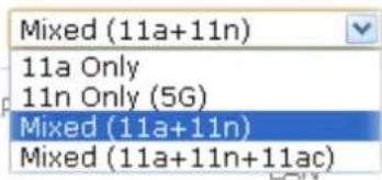 |
| Enable 2 Subnet(Simulate 2 APs) | Check the box to enable the function for two independent subnets. Once you enable this function, LAN-A and LAN-B would be independent. Next, you can connect one router in LAN-A, and another router in LAN-B. Such mechanism can make you feeling that you have two independent AP/subnet functions in one VigorAP 902.If you disable this function, LAN-A and LAN-B ports are in the same domain. You could only connect one router (no matter connecting to LAN-A or LAN-B) in this environment. |
| Hide SSID | Check it to prevent from wireless sniffing and make it harder for unauthorized clients or STAs to join your wireless LAN. Depending on the wireless utility, the user may only see the information except SSID or just cannot see any thing about VigorAP 902 while site surveying. The system allows you to set four sets of SSID for different usage. |
| SSID | Set a name for VigorAP 902 to be identified. When Enable 2 Subnet is enabled, you can specify subnet interface (LAN-A or LAN-B) for each SSID by using the drop down menu. |
| Subnet | Choose LAN-A or LAN-B for each SSID. If you choose LAN-A, the wireless clients connecting to this SSID could only communicate with LAN-A. |
| Isolate Member | Check this box to make the wireless clients (stations) with the same SSID not accessing for each other. |
| VLAN ID | Type the value for such SSID. Packets transferred from such SSID to LAN will be tagged with the number.If your network uses VLANs, you can assign the SSID to a VLAN on your network. Client devices that associate using the SSID are grouped into this VLAN. The VLAN ID range is from 3 to 4095. The VLAN ID is 0 by default, it means disabling the VLAN function for the SSID. |
| Channel | Means the channel of frequency of the wireless LAN. You may switch channel if the selected channel is under serious interference. If you have no idea of choosing the frequency, please selectAutoSelectto let system determine for you. |
| Extension Channel | With 802.11n, there is one option to double the bandwidth per channel. The available extension channel options will be variedaccording to the Channel selected above. Configure the extension channel you want. |
| Channel Width | Auto 20/40/80 MHZ– the AP will use 20MHz or 40MHz or 80MHz for data transmission and receiving according to the station capability. Such channel can increase the performance for data transmission.Auto 20/40 MHZ– the AP will use 20MHz or 40MHz for data transmission and receiving according to the station capability. Such channel can increase the performance for data transmission.20 MHZ- the AP will use 20MHz for data transmission and receiving between the AP and the stations. |
After finishing this web page configuration, please click OK to save the settings.
3.11.2 Security
This page allows you to set security with different modes for SSID 1, 2, 3 and 4 respectively. After configuring the correct settings, please click OK to save and invoke it.
By clicking the Security Settings, a new web page will appear so that you could configure the settings.
Wireless LAN (5GHz) >> Security Settings
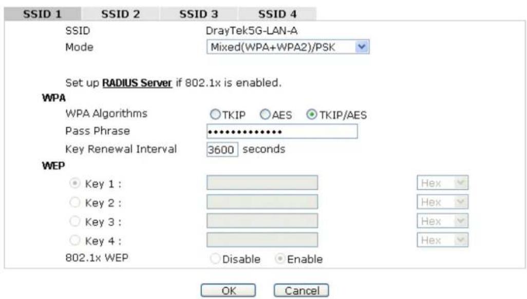
text_image
SSID 1 SSID 2 SSID 3 SSID 4 SSID DrayTek5G-LAN-A Mode Mixed(WPA+WPA2)/PSK Set up RADIUS Server if 802.1x is enabled. WPA WPA Algorithms ○ TKIP ○ AES ● TKIP/AES Pass Phrase •••••••••••• Key Renewal Interval 3600 seconds WEP ● Key 1 : ○ Key 2 : ○ Key 3 : ○ Key 4 : 802.1x WEP ○ Disable ○ Enable Hex Hex Hex Hex OK CancelAvailable settings are explained as follows:
| Item | Description |
| Mode | There are several modes provided for you to choose. |
| DisableDisableWEPWPA/PSKWPA2/PSKMixed(WPA+WPA2)/PSKWEP/802.1xWPA/802.1xWPA2/802.1xMixed(WPA+WPA2)/802.1xDisable - The encryption mechanism is turned off.WEP - Accepts only WEP clients and the encryption key should be entered in WEP Key.WPA/PSK or WPA2/PSK or Mixed (WPA+WPA2)/PSK - Accepts only WPA clients and the encryption key should be entered in PSK. The WPA encrypts each frame transmitted from the radio using the key, which either PSK (Pre-Shared Key) entered manually in this field below or automatically negotiated via 802.1x authentication.WEP/802.1x - The built-in RADIUS client feature enables VigorAP 902 to assist the remote dial-in user or a wireless station and the RADIUS server in performing mutual authentication. It enables centralized remote access authentication for network management.The WPA encrypts each frame transmitted from the radio using the key, which either PSK (Pre-Shared Key) entered manually in this field below or automatically negotiated via 802.1x authentication. Select WPA, WPA2 or Auto as WPA mode.WPA/802.1x - The WPA encrypts each frame transmitted from the radio using the key, which either PSK (Pre-Shared Key) entered manually in this field below or automatically negotiated via 802.1x authentication.WPA2/802.1x - The WPA encrypts each frame transmitted from the radio using the key, which either PSK (Pre-Shared Key) entered manually in this field below or automatically negotiated via 802.1x authentication. | |
| WPA Algorithms | Select TKIP, AES or TKIP/AES as the algorithm for WPA. Such feature is available for WPA2/802.1x, WPA/802.1x, WPA/PSK or WPA2/PSK or Mixed (WPA+WPA2)/PSK mode. |
| Pass Phrase | Either 8~63 ASCII characters, such as 012345678..(or 64 Hexadecimal digits leading by 0x, such as "0x321253abcde..."). Such feature is available for WPA/PSK or WPA2/PSK or Mixed (WPA+WPA2)/PSK mode. |
| Key Renewal Interval | WPA uses shared key for authentication to the network. However, normal network operations use a different encryption key that is randomly generated. This randomly generated key that is periodically replaced. Enter the renewal security time (seconds) in the column. Smaller interval leads to greater security but lower performance. Default is 3600seconds. Set 0 to disable re-key. Such feature is available for WPA2/802.1,WPA/802.1x, WPA/PSK or WPA2/PSK or Mixed (WPA+WPA2)/PSK mode. |
| Key 1 – Key 4 | Four keys can be entered here, but only one key can be selected at a time. The format of WEP Key is restricted to 5 ASCII characters or 10 hexadecimal values in 64-bit encryption level, or restricted to 13 ASCII characters or 26 hexadecimal values in 128-bit encryption level. The allowed content is the ASCII characters from 33(!) to 126(~) except '#' and ','. Such feature is available for WEP mode. |
| 802.1x WEP | Disable - Disable the WEP Encryption. Data sent to the AP will not be encrypted.Enable - Enable the WEP Encryption.Such feature is available for WEP/802.1x mode. |
Click the link of RADIUS Server to access into the following page for more settings.
RADIUS Server
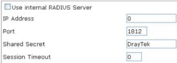
text_image
Use internal RADIUS Server IP Address 0 Port 1812 Shared Secret DrayTek Session Timeout 0
Available settings are explained as follows:
| Item | Description |
| Use internal RADIUS Server | There is a RADIUS server built in VigorAP 902 which is used to authenticate the wireless client connecting to the access point. Check this box to use the internal RADIUS server for wireless security.Besides, if you want to use the external RADIUS server for authentication, do not check this box.Please refer to the section,3.12 RADIUS Server to configure settings for internal server of VigorAP 902. |
| IP Address | Enter the IP address of external RADIUS server. |
| Port | The UDP port number that the external RADIUS server is using. The default value is 1812, based on RFC 2138. |
| Shared Secret | The external RADIUS server and client share a secret that is used to authenticate the messages sent between them. Both sides must be configured to use the same shared secret. |
| Session Timeout | Set the maximum time of service provided beforere-authentication. Set to zero to perform another authentication immediately after the first authentication has successfully completed. (The unit is second.) |
After finishing this web page configuration, please click OK to save the settings.
3.11.3 Access Control
For additional security of wireless access, the Access Control facility allows you to restrict the network access right by controlling the wireless LAN MAC address of client. Only the valid MAC address that has been configured can access the wireless LAN interface. By clicking the Access Control, a new web page will appear, as depicted below, so that you could edit the clients' MAC addresses to control their access rights (deny or allow).
Wireless LAN (5GHz) >> Access Control
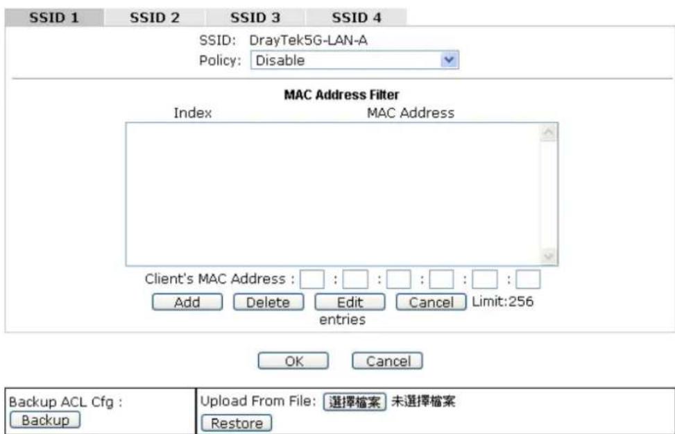
text_image
SSID 1 SSID 2 SSID 3 SSID 4 SSID: DrayTek5G-LAN-A Policy: Disable MAC Address Filter Index MAC Address Client's MAC Address : □ : □ : □ : □ : □ : □ Add Delete Edit Cancel Limit:256 entries OK Cancel Backup ACL Cfg : Backup Upload From File: 選擇檔案 未選擇檔案 RestoreAvailable settings are explained as follows:
| Item | Description |
| Policy | Select to enable any one of the following policy or disable the policy. ChooseActivate MAC address filterto type in the MAC addresses for other clients in the network manually.ChooseBlocked MAC address filter,so that all of the devices with the MAC addresses listed on the MAC Address Filter table will be blocked and cannot access into VigorAP 902.Activate MAC address filterDisableActivate MAC address filterBlocked MAC address filter |
| MAC Address Filter | Display all MAC addresses that are edited before. |
| Client's MAC Address | Manually enter the MAC address of wireless client. |
| Add | Add a new MAC address into the list. |
| Delete | Delete the selected MAC address in the list. |
| Edit | Edit the selected MAC address in the list. |
| Cancel | Give up the access control set up. |
| Backup | Click it to store the settings (MAC addresses on MAC Address Filter table) on this page as a file. |
| Restore | Click it to restore the settings (MAC addresses on MAC Address Filter table) from an existed file. |
After finishing this web page configuration, please click OK to save the settings.
3.11.4 WPS
Open Wireless LAN>>WPS to configure the corresponding settings.
Wireless LAN (5GHz) >> WPS (Wi-Fi Protected Setup)
Enable WPS
Wi-Fi Protected Setup Information
| WPS Configured | Yes |
| WPS SSID | Draytek_5G-LANA |
| WPS Auth Mode | Mixed(WPA+WPA2)/PSK |
| WPS Encryp Type | TKIP/AES |
Device Configure
| Configure via Push Button | Start PBC |
| Configure via Client PinCode |
Status: Idle
Note: WPS can help your wireless client automatically connect to the Access point.
: WPS is Disabled.
: WPS is Enabled.
: Waiting for WPS requests from wireless clients.
Available settings are explained as follows:
| Item | Description |
| Enable WPS | Check this box to enable WPS setting. |
| WPS Configured | Display related system information for WPS. If the wireless security (encryption) function of VigorAP 902 is properly configured, you can see ‘Yes’ message here. |
| WPS SSID | Display current selected SSID. |
| WPS Auth Mode | Display current authentication mode of the VigorAP 902. Only WPA2/PSK and WPA/PSK support WPS. |
| WPS Encrypt Type | Display encryption mode (None, WEP, TKIP, AES, etc.) of VigorAP 902. |
| Configure via Push Button | Click Start PBC to invoke Push-Button style WPS setup procedure. VigorAP 902 will wait for WPS requests from wireless clients about two minutes. Both ACT and 5G WLAN LEDs on VigorAP 902 will blink quickly when WPS is in progress. It will return to normal condition after two minutes. (You need to setup WPS within two minutes) |
| Configure via Client PinCode | Type the PIN code specified in wireless client you wish to connect, and click Start PIN button. Both ACT and 5G WLAN LEDs on VigorAP 902 will blink quickly when WPS is in progress. It will return to normal condition after twominutes. (You need to setup WPS within two minutes). |
3.11.5 Advanced Setting
This page is to determine which algorithm will be selected for wireless transmission rate.
Wireless LAN (2.4GHz) >> Advanced Setting

text_image
Rate Adaptation Algorithm Fragment Length (256 - 2346) RTS Threshold (1 - 2347) Country Code New Old 2346 bytes 2347 bytes (Reference) OK CancelAvailable settings are explained as follows:
| Item | Description |
| Rate Adaptation Algorithm | Wireless transmission rate is adapted dynamically. Usually, performance of “new” algorithm is better than “old”. |
| Fragment Length | Set the Fragment threshold of wireless radio. Do not modify default value if you don’t know what it is, default value is 2346. |
| RTS Threshold | Minimize the collision (unit is bytes) between hidden stations to improve wireless performance.Set the RTS threshold of wireless radio. Do not modify default value if you don’t know what it is, default value is 2347. |
| Country Code | VigorAP broadcasts country codes by following the 802.11d standard. However, some wireless stations will detect / scan the country code to prevent conflict occurred. If conflict is detected, wireless station will be warned and is unable to make network connection. Therefore, changing the country code to ensure successful network connection will be necessary for some clients. |
3.11.6 AP Discovery
VigorAP 902 can scan all regulatory channels and find working APs in the neighborhood. Based on the scanning result, users will know which channel is clean for usage. Also, it can be used to facilitate finding an AP for a WDS link. Notice that during the scanning process (about 5 seconds), no client is allowed to connect to Vigor.
This page is used to scan the existence of the APs on the wireless LAN. Yet, only the AP which is in the same channel of VigorAP 902 can be found. Please click Scan to discover all the connected APs.
Access Point List
| Select SSID | BSSID | RSSI | Channel | Encryption | Authentication |
| Scan | |||||
| Note: During the scanning process (about 5 seconds), no station is allowed to connect with the AP. | |||||
| AP's MAC Address: : : : : : : : : | AP's SSID | ||||
| Select as Universal Repeater: Select | |||||
Each item is explained as follows:
| Item | Description |
| SSID | Display the SSID of the AP scanned by VigorAP 902. |
| BSSID | Display the MAC address of the AP scanned by VigorAP 902. |
| RSSI | Display the signal strength of the access point. RSSI is the abbreviation of Received Signal Strength Indication. |
| Channel | Display the wireless channel used for the AP that is scanned by VigorAP 902. |
| Encryption | Display the encryption mode for the scanned AP. |
| Authentication | Display the authentication type that the scanned AP applied. |
| Scan | It is used to discover all the connected AP. The results will be shown on the box above this button |
| AP's MAC Address | If you want the found AP applying the WDS settings, please type in the AP's MAC address. |
| AP's SSID | To specify an AP to be applied with WDS settings, you can specify MAC address or SSID for the AP. Here is the place that you can type the SSID of the AP. |
| Select as Universal Repeater | In Universal Repeater mode, WAN would work as station mode and the wireless AP can be selected as a universal repeater. Choose one of the wireless APs from the Scan list. |
3.11.7 Universal Repeater
The access point can act as a wireless repeater; it can be Station and AP at the same time. It can use Station function to connect to a Root AP and use AP function to serve all wireless stations within its coverage.
Note: While using Universal Repeater mode, the access point will demodulate the received signal. Please check if this signal is noise for the operating network, then have the signal modulated and amplified again. The output power of this mode is the same as that of WDS and normal AP mode.
Wireless LAN (5GHz) >> Universal Repeater
Universal Repeater Parameters
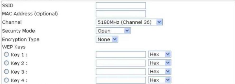
text_image
SSID MAC Address (Optional) Channel 5180MHz (Channel 36) Security Mode Open Encryption Type None WEP Keys Key 1 : Hex Key 2 : Hex Key 3 : Hex Key 4 : HexNote: If Channel is modified, the Channel setting of AP would also be changed.
Universal Repeater IP Configuration

text_image
Connection Type DHCP Router Name AP902
Available settings are explained as follows:
| Item | Description |
| SSID | Set the name of access point that VigorAP 902 wants to connect to. |
| MAC Address(Optional) | Type the MAC address of access point that VigorAP 902 wants to connect to. |
| Channel | Means the channel of frequency of the wireless LAN. The default channel is 36. You may switch channel if the selected channel is under serious interference. If you have no idea of choosing the frequency, please selectAutoSelectto let system determine for you. |
| Security Mode | There are several modes provided for you to choose. Each mode will bring up different parameters (e.g., WEP keys, Pass Phrase) for you to configure.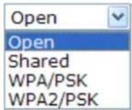 |
| Encryption Type for Open/Shared | This option is available when Open/Shared is selected as Security Mode.Choose None to disable the WEP Encryption. Data sent to the AP will not be encrypted. To enable WEP encryption for data transmission, please choose WEP.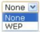 WEP Keys - Four keys can be entered here, but only one key can be selected at a time. The format of WEP Key is restricted to 5 ASCII characters or 10 hexadecimal values in 64-bit encryption level, or restricted to 13 ASCII characters or 26 hexadecimal values in 128-bit encryption level. The allowed content is the ASCII characters from 33(!) to 126(~) except '#' and '.', WEP Keys - Four keys can be entered here, but only one key can be selected at a time. The format of WEP Key is restricted to 5 ASCII characters or 10 hexadecimal values in 64-bit encryption level, or restricted to 13 ASCII characters or 26 hexadecimal values in 128-bit encryption level. The allowed content is the ASCII characters from 33(!) to 126(~) except '#' and '.',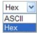 |
| Encryption Type for WPA/PSK and WPA2/PSK | This option is available when WPA/PSK or WPA2/PSK is selected as Security Mode.Select TKIP or AES as the algorithm for WPA.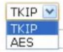 |
| Pass Phrase | Either 8~63 ASCII characters, such as 012345678 (or 64 Hexadecimal digits leading by 0x, such as "0x321253abcde..."). |
| Connection Type | Choose DHCP or Static IP as the connection mode.DHCP – The wireless station will be assigned with an IP from.Static IP – The wireless station shall specify a static IP for connecting to Internet via VigorAP. |
| Router Name | This setting is available when DHCP is selected as Connection Type.Type a name for the VigorAP as identification. Simply use the default name. |
| IP Address | This setting is available when Static IP is selected as Connection Type.Type an IP address with the same network segment of the LAN IP setting of VigorAP. Such IP shall be different with any IP address in LAN. |
| Subnet Mask | This setting is available when Static IP is selected as Connection Type. Type the subnet mask setting which shall be the same as the one configured in LAN for VigorAP. |
| Default Gateway | This setting is available when Static IP is selected as Connection Type. Type the gateway setting which shall be the same as the default gateway configured in LAN for VigorAP. |
After finishing this web page configuration, please click OK to save the settings.
3.11.8 WMM Configuration
WMM is an abbreviation of Wi-Fi Multimedia. It defines the priority levels for four access categories derived from 802.1d (prioritization tabs). The categories are designed with specific types of traffic, voice, video, best effort and low priority data. There are four accessing categories - AC_BE, AC_BK, AC_VI and AC_VO for WMM.
Wireless LAN (5GHz) >> WMM Configuration
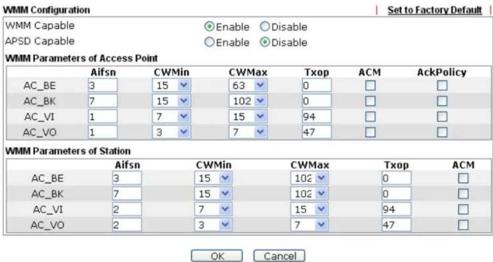
text_image
WMM Configuration Set to Factory Default WMM Capable ● Enable ○ Disable APSD Capable ○ Enable ● Disable WMM Parameters of Access Point Aifsn CWMin CWMax Txop ACM AckPolicy AC_BE 3 15 63 0 □ □ AC_BK 7 15 102 0 □ □ AC_VI 1 7 15 94 □ □ AC_VO 1 3 7 47 □ □ WMM Parameters of Station Aifsn CWMin CWMax Txop ACM AC_BE 3 15 102 0 □ AC_BK 7 15 102 0 □ AC_VI 2 7 15 94 □ AC_VO 2 3 7 47 □ OK CancelAvailable settings are explained as follows:
| Item | Description |
| WMM Capable | To apply WMM parameters for wireless data transmission, please click the Enable radio button. |
| Aifsn | It controls how long the client waits for each data transmission. Please specify the value ranging from 1 to 15. Such parameter will influence the time delay for WMM accessing categories. For the service of voice or video image, please set small value for AC_VI and AC_VO categories For the service of e-mail or web browsing, please set large value for AC_BE and AC_BK categories. |
| CWMin/CWMax | CWMin means contention Window-Min and CWMax means contention Window-Max. Please specify the value ranging from 1 to 15. Be aware that CWMax value must be greater than CWMin or equals to CWMin value. Both values will influencethe time delay for WMM accessing categories. The difference between AC_VI and AC_VO categories must be smaller; however, the difference between AC_BE and AC_BK categories must be greater. |
| Txop | It means transmission opportunity. For WMM categories of AC_VI and AC_VO that need higher priorities in data transmission, please set greater value for them to get highest transmission opportunity. Specify the value ranging from 0 to 65535. |
| ACM | It is an abbreviation of Admission control Mandatory. It can restrict stations from using specific category class if it is checked.Note:VigorAP 902 provides standard WMM configuration in the web page. If you want to modify the parameters, please refer to the Wi-Fi WMM standard specification. |
| AckPolicy | “Uncheck” (default value) the box means the AP will answer the response request while transmitting WMM packets through wireless connection. It can assure that the peer must receive the WMM packets.“Check” the box means the AP will not answer any response request for the transmitting packets. It will have better performance with lower reliability. |
After finishing this web page configuration, please click OK to save the settings.
3.11.9 Bandwidth Management
The downstream or upstream from FTP, HTTP or some P2P applications will occupy large of bandwidth and affect the applications for other programs. Please use Bandwidth Management to make the bandwidth usage more efficient.
Wireless LAN (5GHz) >> Bandwidth Management
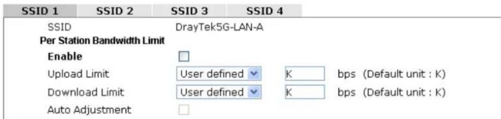
text_image
SSID 1 SSID 2 SSID 3 SSID 4 SSID DrayTek5G-LAN-A Per Station Bandwidth Limit Enable Upload Limit User defined K bps (Default unit : K) Download Limit User defined K bps (Default unit : K) Auto AdjustmentNote: 1. Download : Traffic going to any station. Upload : Traffic being sent from a wireless station.
2. Allow auto adjustment could make the best utilization of available bandwidth.

Available settings are explained as follows:
| Item | Description |
| SSID | Display the specific SSID name. |
| Enable | Check this box to enable the bandwidth management for clients. |
| Upload Limit | Define the maximum speed of the data uploading which will be used for the wireless stations connecting to VigorAP with the same SSID.Use the drop down list to choose the rate. If you choose User defined, you have to specify the rate manually. |
| Download Limit | Define the maximum speed of the data downloading which will be used for the wireless station connecting to VigorAP with the same SSID.Use the drop down list to choose the rate. If you choose User defined, you have to specify the rate manually. |
| Auto Adjustment | Check this box to have the bandwidth limit determined by the system automatically. |
After finishing this web page configuration, please click OK to save the settings.
3.11.10 Airtime Fairness
Airtime fairness is essential in wireless networks that must support critical enterprise applications.
Most of the applications are either symmetric or require more downlink than uplink capacity; telephony and email send the same amount of data in each direction, while video streaming and web surfing involve more traffic sent from access points to clients than the other way around. This is essential for ensuring predictable performance and quality-of-service, as well as allowing 802.11n and legacy clients to coexist on the same network. Without airtime fairness, offices using mixed mode networks risk having legacy clients slow down the entire network or letting the fastest client(s) crowd out other users.
With airtime fairness, every client at a given quality-of-service level has equal access to the network's airtime.
The wireless channel can be accessed by only one wireless station at the same time.
The principle behind the IEEE802.11 channel access mechanisms is that each station has equal probability to access the channel. When wireless stations have similar data rate, this principle leads to a fair result. In this case, stations get similar channel access time which is called airtime.
However, when stations have various data rate (e.g., 11g, 11n), the result is not fair. The slow stations (11g) work in their slow data rate and occupy too much airtime, whereas the fast stations (11n) become much slower.
Take the following figure as an example, both Station A(11g) and Station B(11n) transmit data packets through VigorAP 902. Although they have equal probability to access the wireless channel, Station B(11n) gets only a little airtime and waits too much because Station A(11g) spends longer time to send one packet. In other words, Station B(fast rate) is obstructed by Station A(slow rate).
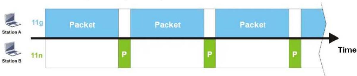
flowchart
graph LR
    A["Station A"] -->|11g| B["Packet"]
    C["Station B"] -->|11n| D["P"]
    B --> E["Packet"]
    E --> F["P"]
    F --> G["Packet"]
    G --> H["P"]
    H --> I["Time"]
To improve this problem, Airtime Fairness is added for VigorAP 902. Airtime Fairness function tries to assign similar airtime to each station (A/B) by controlling TX traffic. In the following figure, Station B(11n) has higher probability to send data packets than Station A(11g). By this way, Station B(fast rate) gets fair airtime and it's speed is not limited by Station A(slow rate).

flowchart
graph LR
    A["Station A"] -->|11g| B["Packet"]
    C["Station B"] -->|11n| D["P P P P P"]
    B --> E["Packet"]
    D --> F["P P P"]
    E --> G["Time"]
    F --> G
    style A fill:#f9f,stroke:#333
    style C fill:#f9f,stroke:#333
    style B fill:#bbf,stroke:#333
    style E fill:#bbf,stroke:#333
    style F fill:#bbf,stroke:#333
It is similar to automatic Bandwidth Limit. The dynamic bandwidth limit of each station depends on instant active station number and airtime assignment. Please note that Airtime Fairness of 2.4GHz and 5GHz are independent. But stations of different SSIDs function together, because they all use the same wireless channel. IN SPECIFIC ENVIRONMENTS, this function can reduce the bad influence of slow wireless devices and improve the overall wireless performance.
Suitable environment:
(1) Many wireless stations.
(2) All stations mainly use download traffic.
(3) The performance bottleneck is wireless connection.
Wireless LAN (5GHz) >> Airtime Fairness

text_image
Enable Airtime Fairness Triggering Client Number (2-64) 2 (default: 2)Note: Please enable or disable this function according to the real situation and user experience. It is NOT suitable for all environments.

Available settings are explained as follows:
| Item | Description |
| Enable Airtime Fairness | Try to assign similar airtime to each wireless station by controlling TX traffic.Airtime Fairness – Click the link to display the following screen of airtime fairness note.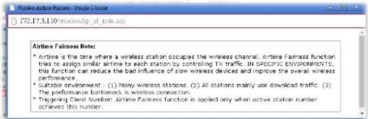 Triggering Client Number –Airtime Fairness function is applied only when active station number achieves this number. Triggering Client Number –Airtime Fairness function is applied only when active station number achieves this number. |
After finishing this web page configuration, please click OK to save the settings.
3.11.11 Station Control
Station Control is used to specify the duration for the wireless client to connect and reconnect VigorAP. If such function is not enabled, the wireless client can connect VigorAP until it shuts down.
Such feature is especially useful for free Wi-Fi service. For example, a coffee shop offers free Wi-Fi service for its guests for one hour every day. Then, the connection time can be set as “1 hour” and reconnection time can be set as “1 day”. Thus, the guest can finish his job within one hour and will not occupy the wireless network for a long time.
Note: Up to 300 Wireless Station records are supported by VigorAP.
Wireless LAN (5GHz) >> Station Control
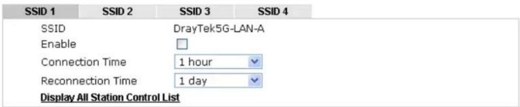
text_image
SSID 1 SSID 2 SSID 3 SSID 4 SSID DrayTek5G-LAN-A Enable Connection Time 1 hour Reconnection Time 1 day Display All Station Control ListNote: Once the feature is enabled, the connection time quota will apply to each wireless client (identified by MAC address).

Available settings are explained as follows:
| Item | Description |
| SSID | Display the SSID that the wireless station will use it to connect with Vigor router. |
| Enable | Check the box to enable the station control function. |
| Connection Time / Reconnection Time | Use the drop down list to choose the duration for the wireless client connecting /reconnecting to Vigor router. Or, type the duration manually when you chooseUser defined.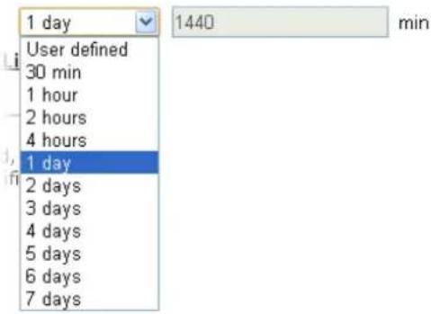 |
| Display All Station Control List | All the wireless stations connecting to Vigor router by using such SSID will be listed on Station Control List. |
After finishing all the settings here, please click OK to save the configuration.
3.11.12 Roaming
The network signal for a single wireless access point might be limited by its coverage range. Therefore, if you want to expand the wireless network in a large exhibition with a quick method, you can install multiple access points with enabling the Roaming feature for each AP to reach the purpose of expanding wireless signals seamlessly.
These access points connecting for each other shall be verified by pre-authentication. This page allows you to enable the roaming feature and the pre-authentication.
Wireless LAN (5GHz) >> Roaming
AP-assisted Client Roaming Parameters
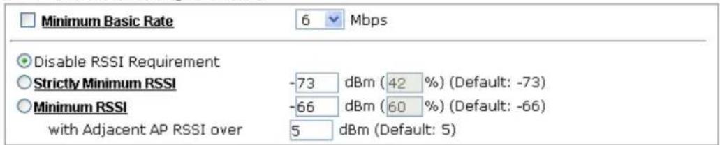
text_image
Minimum Basic Rate 6 Mbps Disable RSSI Requirement Strictly Minimum RSSI -73 dBm (42 %) (Default: -73) Minimum RSSI -66 dBm (60 %) (Default: -66) with Adjacent AP RSSI over 5 dBm (Default: 5)Fast Roaming(WPA/802.1x)

text_image
Enable PMK Caching : Cache Period 10 minute(s) (10 ~ 600) (Default: 10) Pre-Authentication
Available settings are explained as follows:
| Item | Description |
| AP-assisted Client Roaming Parameters | When the link rate of wireless station is too low or the signal received by the wireless station is too worse, VigorAP 902 will automatically detect (based on the link rate and RSSI requirement) and cut off the network connection for that wireless station to assist it to connect another Wireless AP to get better signal. Minimum Basic Rate - Check the box to use the drop down list to specify a basic rate (Mbps). When the link rate of the wireless station is below such value, VigorAP 902 will terminate the network connection for that wireless station. Disable RSSI Requirement - If it is selected, VigorAP will not terminate the network connection based on RSSI. Strictly Minimum RSSI - VigorAP uses RSSI (received signal strength indicator) to decide to terminate the network connection of wireless station. When the signal strength is below the value (dBm) set here, VigorAP 902 will terminate the network connection for that wireless station. Minimum RSSI - When the signal strength of the wireless station is below the value (dBm) set here and adjacent AP (must be DrayTek AP and support such feature too) with higher signal strength value (defined in the field of With Adjacent AP RSSI over) is detected by VigorAP 902, VigorAP 902 will terminate the network connection for that wireless station. Later, the wireless station can connect to the adjacent AP (with betterRSSI).● With Adjacent AP RSSI over – Specify a value as a threshold. |
| Fast Roaming (WPA/802.1x) | Enable – Check the box to enable fast roaming configuration.PMK Cache Period - Set the expire time of WPA2 PMK (Pairwise master key) cache. PMK Cache manages the list from the BSSIDs in the associated SSID with which it has pre-authenticated. Such feature is available for WPA2/802.1 mode.Pre-Authentication - Enables a station to authenticate to multiple APs for roaming securer and faster. With the pre-authentication procedure defined in IEEE 802.11i specification, the pre-four-way-handshake can reduce handoff delay perceivable by a mobile node. It makes roaming faster and more secure. (Only valid in WPA2)Enable - Enable IEEE 802.1X Pre-Authentication.Disable - Disable IEEE 802.1X Pre-Authentication. |
After finishing this web page configuration, please click OK to save the settings.
3.11.13 Station List
Station List provides the knowledge of connecting wireless clients now along with its status code.
General
Display general information (e.g., MAC Address, SSID, Auth, Encrypt, TX/RX Rate) for the station.
Wireless LAN (5GHz) >> Station List
Station List
| General | Advanced | Control | Neighbor | ||||
| Index | MAC Address | Vendor | RSSI | Approx. Distance | SSID | Visit Time | |
| 1 | 80:00:0B:04:CE:5A | Intel | 10%(-86dBm) | 112.20m | N/A | 0d:0h:40m | |
| 2 | DA:Al:19:4B:73:65 | 13%(-85dBm) | 100.00m | N/A | 0d:0h:0m: | ||
| 3 | 00:50:7F:F0:BD:2B | DrayTek | 31%(-77dBm) | 39.8lm | N/A | 0d:0h:38m | |
| 4 | DA:Al:19:8F:ED:6B | 10%(-86dBm) | 112.20m | N/A | 0d:0h:0m: | ||
| 5 | 00:1F:3C:51:9C:55 | Intel | 15%(-84dBm) | 89.13m | N/A | 0d:0h:39m | |
| 6 | 00:1D:AA:7E:87:BA | DrayTek | 10%(-86dBm) | 112.20m | N/A | 0d:0h:0m: | |
| Refresh | |||||||
| Add to Access Control :Client's MAC Address : □ : □ : □ : □ : □ : □ | |||||||
Note: 1. Approx. Distance is calculated by actual signal strength of device detected. Inaccuracy might occur based on barrier encountered. 2. Due to the differences in signal strength for different devices, the calculated value of approximate distance also might be different.
Add
Available settings are explained as follows:
| Item | Description |
| MAC Address | Display the MAC Address for the connecting client. |
| Hostname | Display the host name of the connecting client. |
| SSID | Display the SSID that the wireless client connects to. |
| Auth | Display the authentication that the wireless client uses for connection with such AP. |
| Encrypt | Display the encryption mode used by the wireless client. |
| Tx Rate/Rx Rate | Display the transmission /receiving rate for packets. |
| Refresh | Click this button to refresh the status of station list. |
| Add to Access Control | Client's MAC Address - For additional security of wireless access, the Access Control facility allows you to restrict the network access right by controlling the wireless LAN MAC address of client. Only the valid MAC address that has been configured can access the wireless LAN interface. |
| Add | Click this button to add current typed MAC address into Access Control. |
Advanced
Display more information (e.g., AID, PSM, WMM, RSSI PhMd, BW, MCS, Rate) for the station.
Control
Display connection and reconnection time of the wireless stations.
Neighbor
Display more information for the neighboring wireless stations.
3.12 RADIUS Setting
3.12.1 RADIUS Server
VigorAP 902 offers a built-in RADIUS server to authenticate the wireless client that tries to connect to VigorAP 902. The AP can accept the wireless connection authentication requested by wireless clients.
RADIUS Setting >> RADIUS Server Configuration

Enable RADIUS Server
Authentication Type

Users Profile (up to 96 users)

text_image
Username Password Confirm Password Configure Add Cancel NO. Username Select Delete Selected Delete AllAuthentication Client (up to 16 clients)

text_image
Client IP Secret Key Confirm Secret Key Configure Add Cancel NO. Client IP Select Delete Selected Delete All
| Backup Radius Cfg : Backup | Upload From File: 选择档案 未选择档案 Restore |
Available settings are explained as follows:
| Item | Description |
| Enable RADIUS Server | Check it to enable the internal RADIUS server. |
| Authentication Type | Let the user to choose the authentication method for RADIUS server.Radius EAP Type – There are two types, PEAP and EAP TLS, offered for selection. If EAP TLS is selected, a certificate must be installed or must be ensured to be trusted. |
| Users Profile | Username – Type a new name for the user profile.Password – Type a new password for such new user profile.Confirm Password – Retype the password to confirm it.ConfigureAdd– Make a new user profile with the name and password specified on the left boxes.Cancel– Clear current settings for user profile.Delete Selected– Delete the selected user profile (s).Delete All – Delete all of the user profiles. |
| Authentication Client | This internal RADIUS server of VigorAP 902 can be treated as the external RADIUS server for other users. Specify the client IP and secret key to make the wireless client choosing VigorAP 902 as its external RADUIS server.Client IP – Type the IP address for the user to be authenticated by VigorAP 902 when the user tries to use VigorAP 902 as the external RADIUS server.Secret Key – Type the password for the user to be authenticated by VigorAP 902 while the user tries to use VigorAP 902 as the external RADIUS server.Confirm Secrete Key – Type the password again for confirmation.ConfigureAdd– Make a new client with IP and secrete key specified on the left boxes.Cancel– Clear current settings for the client.Delete Selected– Delete the selected client(s).Delete All– Delete all of the clients. |
| Backup | Click it to store the settings (RADIUS configuration) on this page as a file. |
| Restore | Click it to restore the settings (RADIUS configuration) from an existed file. |
After finishing this web page configuration, please click OK to save the settings.
3.12.2 Certificate Management
When the local client and remote server are required to make certificate authentication (e.g., Radius EAP-TLS authentication) for wireless connection and avoiding the attack of MITM, a trusted root certificate authority (Root CA) will be used to authenticate the digital certificates offered by both ends.
However, the procedure of applying digital certificate from a trusted root certificate authority is complicated and time-consuming. Therefore, Vigor AP offers a mechanism which allows you to generate root CA to save time and provide convenience for general user. Later, such root CA generated by DrayTek server can perform the issuing of local certificate.
Root CA can be deleted but not edited. If you want to modify the settings for a Root CA, please delete the one and create another one by clicking Create Root CA.
RADIUS Setting >> X509 Trusted CA Certificate Configuration
| Name | Subject | Status | Modify |
| Root CA | --- | --- | Create Root CA |
Note: 1. Please setup the "System Maintenance >> Time and Date" correctly before you try to generate a RootCA.
2. The Time Zone MUST be setup correctly.
Click Create Root CA to open the following page. Type or choose all the information that the window request such as subject name, key type, key size and so on.
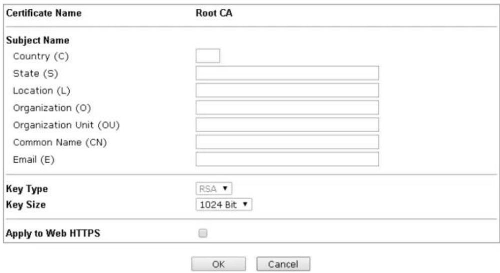
text_image
Certificate Name Root CA Subject Name Country (C) State (S) Location (L) Organization (O) Organization Unit (OU) Common Name (CN) Email (E) Key Type RSA ▼ Key Size 1024 Bit ▼ Apply to Web HTTPS OK CancelAvailable settings are explained as follows:
| Item | Description |
| Subject Name | Type the required information for creating a root CA.Country (C) – Type the country code (two characters) in this box.State (S)/ Location (L)/ Organization (O)/ Organization Unit (OU) /Common Name (CN) - Type the name or information for the root CA with length less than 32 characters.Email (E) – Type the email address for the root CA with length less than 32 characters. |
| Key Type | At present, only RSA (an encryption algorithm) is supported by such device. |
| Key Size | To determine the size of a key to be authenticated, use the drop down list to specify the one you need. |
| Apply to Web HTTPS | VigorAP needs a certificate to access into Internet via Web HTTPS.Check this box to use the user-defined root CA certificate which will substitute for the original certificate applied by web HTTPS. |
Note: "Common Name" must be configured with rotuer's WAN IP or domain name.
After finishing this web page configuration, please click OK to save the settings. A new root CA will be generated.
3.13 Applications
Below shows the menu items for Applications.
Applications
Schedule
Apple iOS Keep Alive
Temperature Sensor
3.13.1 Schedule
The VigorAP has a built-in clock which can update itself manually or automatically by means of Network Time Protocols (NTP). As a result, you can not only schedule the AP to dialup to the Internet at a specified time, but also restrict Internet access to certain hours so that users can connect to the Internet only during certain hours, say, business hours. The schedule is also applicable to other functions.
You have to set your time before set schedule. In System Maintenance>> Time and Date menu, press Inquire Time button to set the VigorAP's clock to current time of your PC. The clock will reset once if you power down or reset the AP. There is another way to set up time. You can inquiry an NTP server (a time server) on the Internet to synchronize the AP's clock. This method can only be applied when the WAN connection has been built up.
Applications >> Schedule
Schedule

Enable Schedule
OK
Schedule Configuration
Index.
1
Setting
Available settings are explained as follows:
| Item | Description |
| Schedule | Enable Schedule - Check it to enable the function of schedule configuration. |
| Schedule Configuration | Index – Display the sort number of the schedule profile.Setting – Display the summary of the schedule profile.Action – Display the action adopted by the schedule profile.Status – Display if the profile is enabled (V) or not (X).Add – Such button is available when Enable Schedule is checked. It allows to add a new schedule profile.Delete – Check the index box of the schedule profile and click such button to remove the profile. |
You can set up to 15 schedules. To add a schedule:
-
Check the box of Enable Schedule.
-
Click the Add button to open the following web page.
Applications >> Schedule
Add Schedule
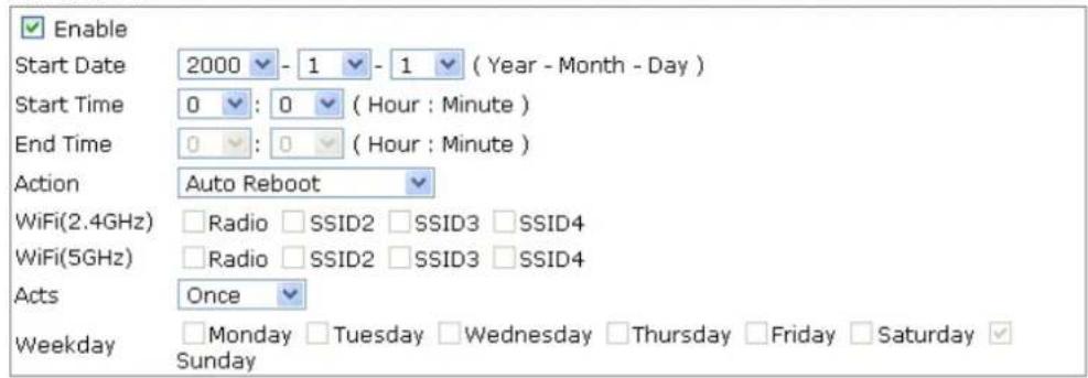
text_image
Enable Start Date 2000 - 1 - 1 (Year - Month - Day) Start Time 0 : 0 (Hour : Minute) End Time 0 : 0 (Hour : Minute) Action Auto Reboot WiFi(2.4GHz) Radio SSID2 SSID3 SSID4 WiFi(5GHz) Radio SSID2 SSID3 SSID4 Acts Once Weekday Monday Tuesday Wednesday Thursday Friday Saturday Sunday
Available settings are explained as follows:
| Item | Description |
| Enable | Check to enable such schedule profile. |
| Start Date | Specify the starting date of the schedule. |
| Start Time | Specify the starting time of the schedule. |
| End Time | Specify the ending time of the schedule. |
| Action | Specify which action should apply the schedule.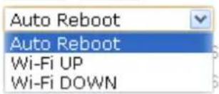 |
| WiFi(2.4GHz)/WiFi(5GHz) | When Wi-Fi UP or Wi-Fi DOWN is selected as Action, you can check the Radio or SSID 2~4 boxes (2.4GHz and 5GHz respectively) to setup the network based on the schedule profile.Note: When Radio is selected, SSID2, SSID3 and SSID4 are not available for choosing, vice versa. |
| Acts | Specify how often the schedule will be applied.Once -The schedule will be applied just onceRoutine -Specify which days in one week should perform the schedule.RoutineOnceRoutine |
| Weekday | Choose and check the day to perform the schedule. It is available when Routine is selected as Acts. |
- After finishing this web page configuration, please click OK to save the settings. A new schedule profile has been created and displayed on the screen.
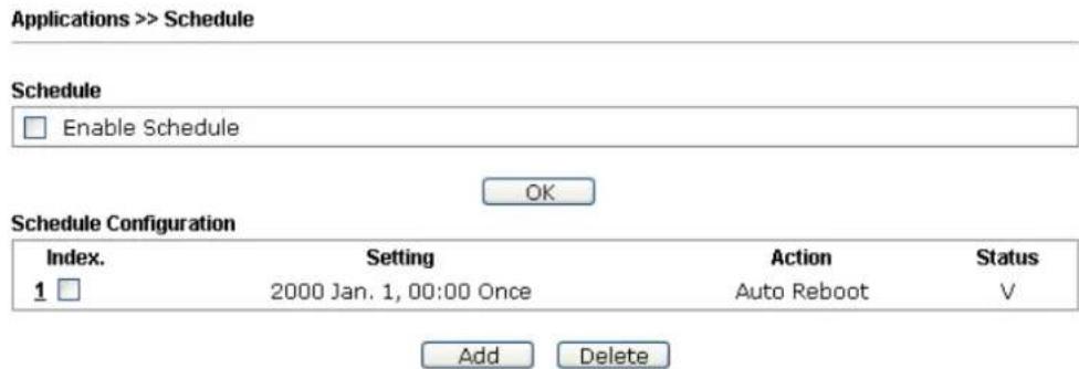
text_image
Applications >> Schedule Schedule Enable Schedule OK Schedule Configuration Index. Setting Action Status 1 □ 2000 Jan. 1, 00:00 Once Auto Reboot V Add Delete3.13.2 Apple iOS Keep Alive
To keep the wireless connection (via Wi-Fi) on iOS device in alive, VigorAP 902 will send the UDP packets with 5353 port to the specific IP every five seconds.
Applications >> Apple iOS Keep Alive
Enable Apple iOS Keep Alive
Apple iOS Keep Alive:
Apple iOS Keep Alive can keep Wifi connection of iOS device by sending UDP port 5353 packets every 5 seconds.
| Index | Apple iOS Keep Alive IP Address | Index | Apple iOS Keep Alive IP Address |
| 1 | 2 | ||
| 3 | 4 | ||
| 5 | 6 |

Available settings are explained as follows:
| Item | Description |
| Enable Apple iOS Keep Alive | Check to enable the function. |
| Index | Display the setting link. Click the index link to open the configuration page for setting the IP address. |
| Apple iOS Keep Alive IP Address | Display the IP address. |
3.13.3 Temperature Sensor
A USB Thermometer is now available that complements your installed DrayTek AP installations that will help you monitor the server or data communications room environment and notify you if the server room or data communications room is overheating.

natural_image
Close-up of a USB temperature sensor with coiled cable and a small black square component (no text or symbols visible)During summer in particular, it is important to ensure that your server or data communications equipment are not overheating due to cooling system failures.
The inclusion of a USB thermometer in compatible VigorAP will continuously monitor the temperature of its environment. When a pre-determined threshold is reached you will be alerted via Syslog.
Temperature Sensor Settings
Applications >> Temperature Sensor Setting
Temperature Sensor Graph Temperature Sensor Settings
Display Settings
Calibration Offset
Temperature Unit


Alarm Settings
Enable Syslog Alarm
High Alarm
Low Alarm
OK
Available settings are explained as follows:
| Item | Description |
| Display Settings | Calibration Offset- Type a value used for correcting the temperature error.Temperature Unit - Choose the display unit of the temperature. There are two types for you to choose. |
| Alarm Settings | Enable Syslog Alarm - The temperature log containing the alarm message will be recorded on Syslog if it is enabled.High Alarm/Low Alarm - Type the upper limit and lower limit for the system to send out temperature alert. |
Temperature Sensor Graph
Below shows an example of temperature graph:
Applications >> Temperature Sensor Graph
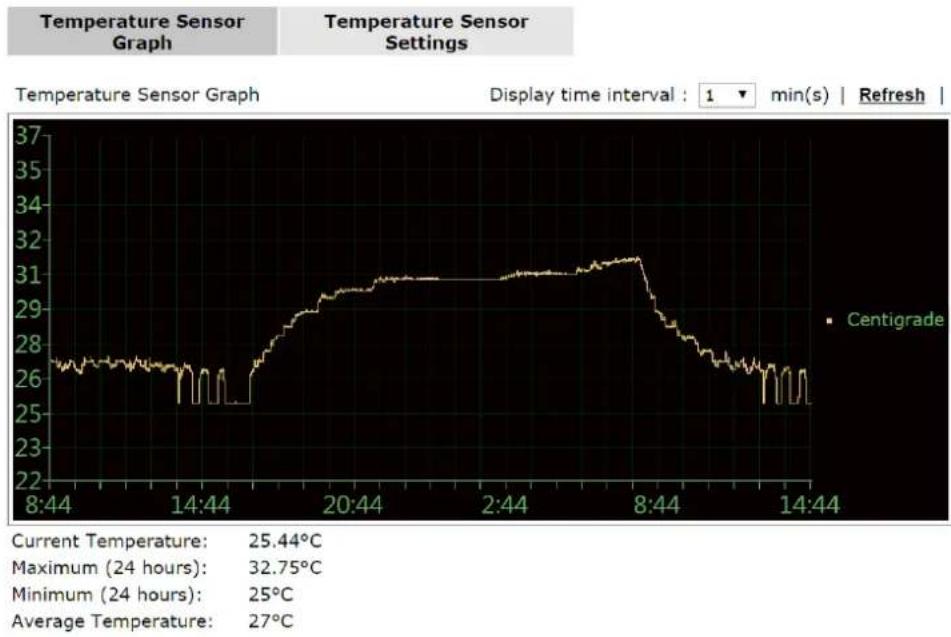
line
| Current Temperature | 25.44°C | | ------------------- | ------- | | Maximum (24 hours) | 32.75°C | | Minimum (24 hours) | 25°C | | Average Temperature | 27°C |3.14 Mobile Device Management
Such feature can control / manage the mobile devices accessing the wireless network of VigorAP. VigorAP offers wireless LAN service for mobile device(s), PC users, MAC users or other users according to the policy selected.
Below shows the menu items for Mobile Device Management.
Mobile Device Management
Detection
Policies
Statistics
3.14.1 Detection
Such page displays mobile device(s) detected by VigorAP Detected device(s) with Policy – Pass can access into the wireless LAN offered by VigorAP. Detected device(s) with Policy – Block are not allowed to access into Internet via VigorAP's WLAN.
Mobile Device Management >> Detection

Enable Mobile Device Management
| Index | OS | MAC | Vendor | Model | Policy |
| 1 | F0:DB:F8:1C:E4:9F | Apple | iPad | Pass | |
| 2 | F4:F1:5A:8A:E8:89 | Apple | iPhone | Pass | |
| 3 | 60:FA:CD:71:9B:91 | Apple | Detecting | Pass | |
| 4 | 44:2A:60:80:15:D6 | Apple | Detecting | Pass |
Note: Please make sure your internet access is available before enabling MDM.

iOS

Android

Windows

Linux

Others
OK
Cancel
Once you check/uncheck the box of Enable Mobile Device Management and click OK, VigorAP will reboot automatically to activate MDM.
At present, OS (for mobile device) categories supported by VigorAP include:
- Windows
- Linux
- iOS
- Andorid
- WindowsPhone
- BlackBerry
- Symbian.
3.14.2 Policy
Such page determines which devices (mobile, PC, MAC or others) allowed to make network connections via VigorAP or blocked by VigorAP.
Mobile Device Management >> Policy
√ Block Mobile Connections (OS: Android,iOS...)
Block PC Connections (OS:Windows,Linux,iMac...)
Block Unknown Connections (OS:Others)

Each item is explained as follows:
| Item | Description |
| Block Mobile Connections | All of mobile devices will be blocked and not allowed to access into Internet via VigorAP. |
| Block PC Connections | All of network connections based on PC, MAC or Linux platform will be blocked and terminated. |
| Block Unknown Connections | Only the unknown network connections (unable to be recognized by Vigor router) will be blocked and terminated. |
After finished the policy selection, click OK. VigorAP will reboot to activate the new policy automatically.
3.14.3 Statistics
The number of detected devices and the number of device(s) passed/blocked according to the policy specified in Mobile Device Management>>Policy can be illustrated as doughnut chart.
Mobile Device Management >> Statistics
Device OS Statistics
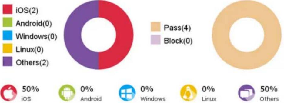
iOS(2)
Android(0)
Windows(0)
Linux(0)
Others(2)
50%
iOS
0%
Android
0%
Windows
0%
Linux
50%
Others
Trademark Notice and Attribution:
- The Android robot is reproduced or modified from work created and shared by Google and used according to the terms described in the Creative Commons 3.0 Attribution License.
- Android is a trademark of Google Inc..
- Tux logo was created by Larry Ewing and The GIMP in 1996.
3.15 System Maintenance
For the system setup, there are several items that you have to know the way of configuration: Status, TR-069, Administrator Password, Configuration Backup, Reboot System, Firmware Upgrade.
Below shows the menu items for System Maintenance.
System Maintenance
System Status
TR-069
Administration Password
Configuration Backup
Syslog / Mail Alert
Time and Date
Management
Reboot System
Firmware Upgrade
3.15.1 System Status
The System Status provides basic network settings of Vigor modem. It includes LAN and WAN interface information. Also, you could get the current running firmware version or firmware related information from this presentation.
System Status
| Model | :VigorAP902 |
| Device Name | :VigorAP902 |
| Firmware Version | :1.1.7 |
| Build Date/Time | :r6061 Thu Apr 28 12:11:38 CST 2016 |
| System Uptime | :0d 01:42:36 |
| Operation Mode | :AP |
| System | |
| Memory Total : 62332 kBMemory Left : 21568 kBCached : 21644 kB / 62332 kBMemory | |
| Wireless LAN (2.4GHz) | |
| MAC Address : 00:1D:AA:3D:55:DASSID : DrayTek-LAN-AChannel : 11Driver Version : 2.7.2.0 | |
| Wireless LAN (5GHz) | |
| MAC Address : 00:1D:AA:3D:55:DBSSID : DrayTek5G-LAN-AChannel : 36Driver Version : 3.0.3.2 |
| LAN-A | |
| MAC Address | : 00:1D:AA:3D:55:DA |
| IP Address | : 192.168.1.2 |
| IP Mask | : 255.255.255.0 |
| LAN-B | |
| MAC Address | : 00:1D:AA:3D:55:DA |
| IP Address | : 192.168.2.2 |
| IP Mask | : 255.255.255.0 |
Each item is explained as follows:
| Item | Description |
| Model /Device Name | Display the model name of the modem. |
| Firmware Version | Display the firmware version of the modem. |
| Build Date/Time | Display the date and time of the current firmware build. |
| System Uptime | Display the period that such device connects to Internet. |
| Operation Mode | Display the operation mode that the device used. |
| System | |
| Memory total | Display the total memory of your system. |
| Memory left | Display the remaining memory of your system. |
| LAN-A/LAN-B | |
| MAC Address | Display the MAC address of the LAN Interface. |
| IP Address | Display the IP address of the LAN interface. |
| IP Mask | Display the subnet mask address of the LAN interface. |
| Wireless LAN (2.4GHz/5GHz) | |
| MAC Address | Display the MAC address of the WAN Interface. |
| SSID | Display the SSID of the device. |
| Channel | Display the channel that the station used for connecting with such device. |
3.15.2 TR-069
This device supports TR-069 standard. It is very convenient for an administrator to manage a TR-069 device (Vigor router, AP and etc.) through VigorACS SI (Auto Configuration Server).
System Maintenance >> TR-069 Settings
ACS Settings
| URL | |
| Username | |
| Password |
CPE Settings
| Enable | |
| On | LAN-A |
| URL | http://192.168.1.2:8069/cwm/CRN.html |
| Port | 8069 |
| Username | vigor |
| Password | ********** |
| DNS Server IP Address | |
| Primary IP Address | |
| Secondary IP Address | |
Note: Please set default gateway, no matter choose LAN-A or LAN-B.
Periodic Inform Settings
| Enable | ✓ | |
| Interval Time | 900 | second(s) |
STUN Settings
| Enable Disable | |
| Server Address | |
| Server Port | 3478 |
| Minimum Keep Alive Period | 60 Second(s) |
| Maximum Keep Alive Period | -1 second(s) |

Available settings are explained as follows:
| Item | Description |
| ACS Settings | URL/Username/Password – Such data must be typed according to the ACS (Auto Configuration Server) you want to link. Please refer to Auto Configuration Server user's manual for detailed information. The setting for URL can be domain name or IP address. |
| CPE Settings | Such information is useful for Auto Configuration Server (ACS). Enable– Check the box to allow the CPE Client to connect withAuto Configuration Server.On – Choose the interface (LAN-A or LAN-B) for VigorAP 902 connecting to ACS server.Port – Sometimes, port conflict might be occurred. To solve such problem, you might change port number for CPE.DNS Server IP Address – Such field is to specify the IP address if a URL is configured with a domain name.● Primary IP Address –You must specify a DNS server IP address here because your ISP should provide you with usually more than one DNS Server. If your ISP does not provide it, the modem will automatically apply default DNS Server IP address: 194.109.6.66 to this field.● Secondary IP Address –You can specify secondary DNS server IP address here because your ISP often provides you more than one DNS Server. If your ISP does not provide it, the modem will automatically apply default secondary DNS Server IP address: 194.98.0.1 to this field. |
| Periodic Inform Settings | The default setting is Enable. Please set interval time or schedule time for the AP to send notification to VigorACS server. Or click Disable to close the mechanism of notification.Interval Time – Type the value for the interval time setting. The unit is “second”. |
| STUN Settings | The default is Disable. If you click Enable, please type the relational settings listed below:Server Address – Type the IP address of the STUN server.Server Port – Type the port number of the STUN server.Minimum Keep Alive Period – If STUN is enabled, the CPE must send binding request to the server for the purpose of maintaining the binding in the Gateway. Please type a number as the minimum period. The default setting is “60 seconds”.Maximum Keep Alive Period – If STUN is enabled, the CPE must send binding request to the server for the purpose of maintaining the binding in the Gateway. Please type a number as the maximum period. A value of “-1” indicates that no maximum period is specified. |
After finishing this web page configuration, please click OK to save the settings.
3.15.3 Administrator Password
This page allows you to set new password.
System Maintenance >> Administration Password
Administrator Settings
| Account | admin |
| Password | ...... |
| Confirm Password |
Note: Authorization can contain only a-z A-Z 0-9, \~ ' ! @ # \$ % ^ & * () _ + = {} [] | \; '< > . ? /

Available settings are explained as follows:
| Item | Description |
| Account | Type the name for accessing into Web User Interface. |
| Password | Type in new password in this filed. |
| Confirm Password | Type the new password again for confirmation. |
When you click OK, the login window will appear. Please use the new password to access into the web user interface again.
3.15.4 Configuration Backup
Backup the Configuration
Follow the steps below to backup your configuration.
- Go to System Maintenance >> Configuration Backup. The following windows will be popped-up, as shown below.
System Maintenance >> Configuration Backup
Configuration Backup / Restoration
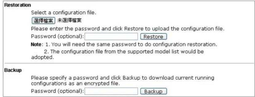
text_image
Restoration Select a configuration file. 選擇檔案 未選擇檔案 Please enter the password and click Restore to upload the configuration file. Password (optional): Restore Note: 1. You will need the same password to do configuration restoration. 2. The configuration file from the supported model list would be adopted. Backup Please specify a password and click Backup to download current running configurations as an encrypted file. Password (optional): Backup- Click Backup button to get into the following dialog. Click Save button to open another dialog for saving configuration as a file.
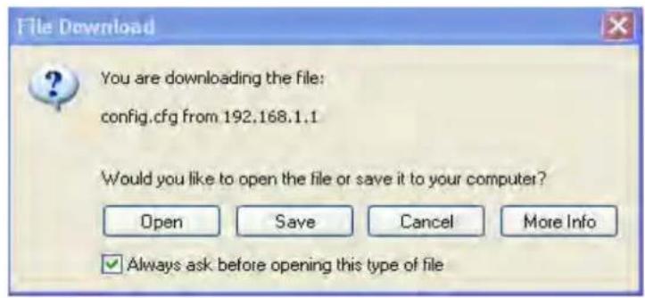
text_image
File Download You are downloading the file: config.cfg from 192.168.1.1 Would you like to open the file or save it to your computer? Open Save Cancel More Info ✓ Always ask before opening this type of file- In Save As dialog, the default filename is config.cfg. You could give it another name by yourself.
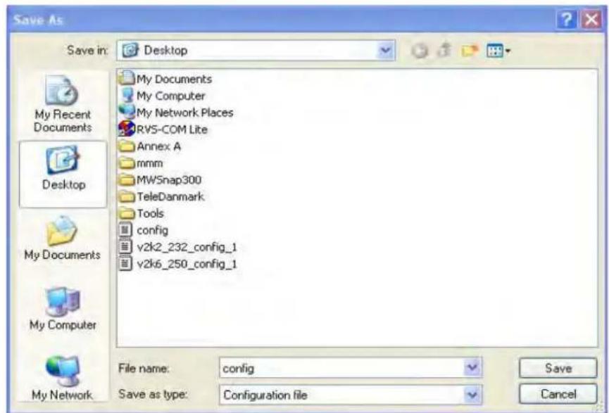
text_image
Save As Save in: Desktop My Documents My Computer My Network Places RV5-COM Lite Annex A mmm MWSnap300 TeleDanmark Tools config v2k2_232_config_1 v2k6_250_config_1 File name: config Save as type: Configuration file Save Cancel- Click Save button, the configuration will download automatically to your computer as a file named config.cfg.
The above example is using Windows platform for demonstrating examples. The Mac or Linux platform will appear different windows, but the backup function is still available.
Note: Backup for Certification must be done independently. The Configuration Backup does not include information of Certificate.
Restore Configuration
- Go to System Maintenance >> Configuration Backup. The following windows will be popped-up, as shown below.
System Maintenance >> Configuration Backup
Configuration Backup / Restoration
Restoration
Select a configuration file.
選擇檔案 未選擇檔案
Please enter the password and click Restore to upload the configuration file.
Password (optional): Restore
Note: 1. You will need the same password to do configuration restoration.
- The configuration file from the supported model list would be adopted.
Backup
Please specify a password and click Backup to download current running configurations as an encrypted file.
Password (optional): Backup
-
Click Browse button to choose the correct configuration file for uploading to the modem.
-
Click Restore button and wait for few seconds, the following picture will tell you that the restoration procedure is successful.
3.15.5 Syslog/MaiI Alert
SysLog function is provided for users to monitor AP. There is no bother to directly get into the Web user interface of the AP or borrow debug equipments.
System Maintenance >> Syslog / Mail Alert Setup
Syslog Access Setup

text_image
Enable Server IP Address Destination Port 514 Log Level AllMail Alert Setup
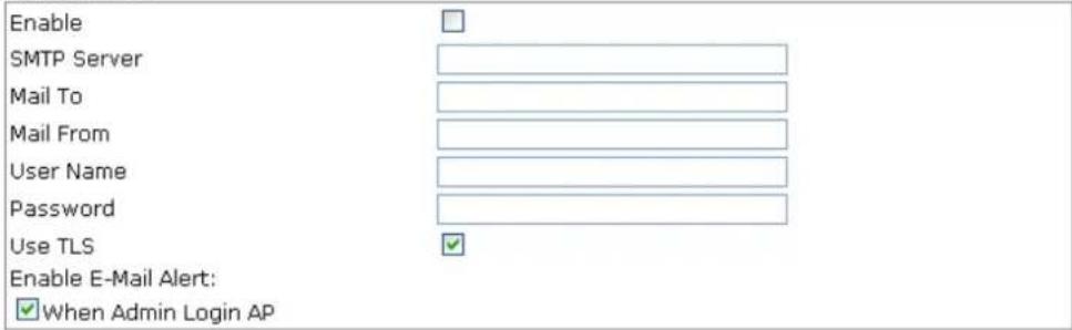
text_image
Enable SMTP Server Mail To Mail From User Name Password Use TLS Enable E-Mail Alert: ✓ When Admin Login AP
Available settings are explained as follows:
| Item | Description |
| Syslog Access Setup | Enable - Check Enable to activate function of Syslog.Server IP Address -The IP address of the Syslog server.Destination Port -Assign a port for the Syslog protocol. The default setting is 514.Log Level - Specify which level of the severity of the event will be recorded by Syslog. |
| Mail Alert Setup | Check Enable to activate function of mail alert.SMTP Server - The IP address of the SMTP server.Mail To - Assign a mail address for sending mails out.Mail From - Assign a path for receiving the mail from outside.User Name - Type the user name for authentication.Password - Type the password for authentication.Use TLS – Check this box to encrypt alert mail. However, if the SMTP server specified here does not support TLS protocol, the alert mail with encrypted data will not be received by the receiver.Enable E-Mail Alert - VigorAP will send an e-mail out when a user accesses into the user interface by using web or telnet. |
3.15.6 Time and Date
It allows you to specify where the time of VigorAP should be inquired from.
System Maintenance >> Time and Date
Time Information
Current System Time
Fri Jun 21 15:03:41 GMT 2013
Inquire Time
Time Setting
Use Browser Time
Use NTP Client
Time Zone
NTP Server
Daylight Saving
NTP synchronization
(GMT-11:00) Midway Island, Samoa

30 sec

OK
Cancel
Available parameters are explained as follows:
| Item | Description |
| Current System Time | Click Inquire Time to get the current time. |
| Use Browser Time | Select this option to use the browser time from the remote administrator PC host as router’s system time. |
| Use NTP Client | Select to inquire time information from Time Server on the Internet using assigned protocol. |
| Time Zone | Select a time protocol. |
| NTP Server | Type the IP address of the time server.Use Default – Click it to choose the default NTP server. |
| Daylight Saving | Check the box to enable the daylight saving. Such feature is available for certain area. |
| NTP synchronization | Select a time interval for updating from the NTP server. |
Click OK to save these settings.
3.15.7 Management
This page allows you to specify the port number for HTTP and HTTPS server.
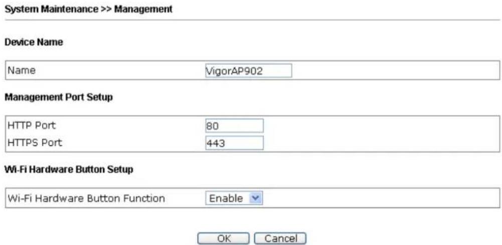
text_image
System Maintenance >> Management Device Name Name VigorAP902 Management Port Setup HTTP Port 80 HTTPS Port 443 Wi-Fi Hardware Button Setup Wi-Fi Hardware Button Function Enable OK CancelAvailable parameters are explained as follows:
| Item | Description |
| Device Name | Name - The default setting is VigorAP 902. Change the name if required. |
| Management Port Setup | HTTP port/HTTPS port -Specify user-defined port numbers for the HTTP and HTTPS servers. |
| Wi-Fi Hardware Button Setup | Stop people manually disabling the wireless if they do not have the right of administration to access to the device.Enable – Choose it to enable the hardware button function.Disable – Choose it to disable the hardware button function. |
3.15.8 Reboot System
The web user interface may be used to restart your modem. Click Reboot System from System Maintenance to open the following page.
System Maintenance >> Reboot System
Reboot System
Do You want to reboot your router?
Using current configuration
○ Using factory default configuration
OK
If you want to reboot the modem using the current configuration, check Using current configuration and click OK. To reset the modem settings to default values, check Using factory default configuration and click OK. The modem will take 5 seconds to reboot the system.
Note: When the system pops up Reboot System web page after you configure web settings, please click OK to reboot your modem for ensuring normal operation and preventing unexpected errors of the modem in the future.
3.15.9 Firmware Upgrade
Before upgrading your modem firmware, you need to install the Modem Tools. The Firmware Upgrade Utility is included in the tools. The following web page will guide you to upgrade firmware by using an example. Note that this example is running over Windows OS (Operating System).
Download the newest firmware from DrayTek's web site or FTP site. The DrayTek web site is www.draytek.com (or local DrayTek's web site) and FTP site is ftp.draytek.com.
Click System Maintenance>> Firmware Upgrade to launch the Firmware Upgrade Utility.
System Maintenance >> Firmware Upgrade
Firmware Update
Select a firmware file.
Browse.
Click Upgrade to upload the file.
Upgrade
Click Browse to locate the newest firmware from your hard disk and click Upgrade.
3.16 Diagnostics
Diagnostic Tools provide a useful way to view or diagnose the status of your VigorAP 902.
Diagnostics
System Log
Speed Test
Traffic Graph
WLAN (2.4GHz) Statistics
WLAN (5GHz) Statistics
3.16.1 System Log
At present, only System Log is offered.
Diagnostics >> System Log
System Log Information
0d 00:00:23 kernel: <-- RTMPAllocAdapterBlock, Status=0
0d 00:00:23 kernel: pAd->CSRBaseAddress =0xc07c0000, csr_addr=0xc07c0000!
0d 00:00:23 kernel: RtmpEepromGetDefault::e2p_default=2
0d 00:00:23 kernel: RtmpChipOpsEepromHook::e2p_type=2, inf_Type=5
0d 00:00:23 kernel: NVM is FLASH mode
0d 00:00:23 kernel: RX DESC a22af000 size = 4096
0d 00:00:23 kernel: WirelessRoaming_en=0
0d 00:00:23 kernel: WirelessRoaming_rate_en=0
0d 00:00:23 kernel: WirelessRoaming_rate_5g_en=0
0d 00:00:23 kernel: WirelessRoaming_rate=0
0d 00:00:23 kernel: WirelessRoaming_rate_5g=0
0d 00:00:23 kernel: STA_CTL=
0d 00:00:23 kernel: default ApCliAPSDCapable[0]=0
0d 00:00:23 kernel: l - TotalAllowedStaNum = 64.
0d 00:00:23 kernel: KeylStr is Invalid key length(0) or Type(0)
0d 00:00:23 kernel: KeylStr is Invalid key length(0) or Type(0)
3.16.2 Speed Test
Click the Start button on the page to test the speed. Such feature can help you to find the best installation place for Vigor AP.
Diagnostics >> Speed Test
Speed Test
Welcome to VigorAP902 Speed Test.
This test allows you to find out the best place for VigorAP902. You can execute the speed test at different places of the building and select the best location for it. The performance test result is only for your reference.
Start
3.16.3 Traffic Graph
Click Traffic Graph to open the web page. Choose one of the managed Access Points, LAN-A or LAN-B, daily or weekly for viewing data transmission chart. Click Refresh to renew the graph at any time.
Diagnostics >> Traffic Graph
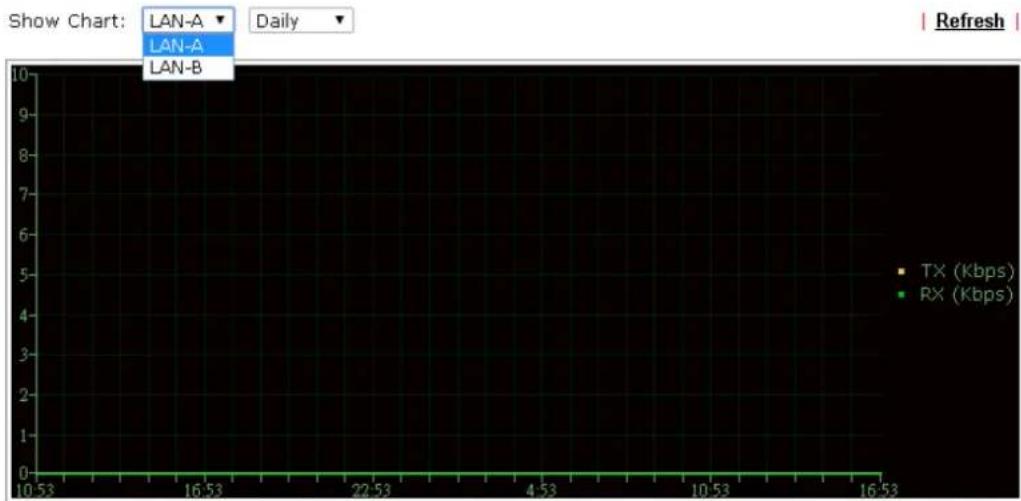
line
| Time | TX (Kbps) | RX (Kbps) | |--------|-----------|-----------| | 10:53 | 0 | 0 | | 16:53 | 0 | 0 | | 22:53 | 0 | 0 | | 4:53 | 0 | 0 | | 10:53 | 0 | 0 | | 16:53 | 0 | 0 |The horizontal axis represents time; the vertical axis represents the transmission rate (in kbps).
3.16.4 WLAN (2.4GHz) Statistics
Such page is used for debug by RD only.
Diagnostics >> WLAN (2.4GHz) Statistics
Auto-Refresh Refresh
| Tx success | 43846 | Rx success | 387111 |
| Tx retry count | 0 | Rx with CRC | 145551 |
| Tx fail to Rcv ACK after retry | 0 | Rx drop due to out of resource | 0 |
| RTS Success Rcv CTS | 0 | Rx duplicate frame | 0 |
| RTS Fail Rcv CTS | 0 | False CCA (one second) | 0 |
| TransmitCountFromOS | 1007 | MulticastReceivedFrameCount | 0 |
| TransmittedFragmentCount | 43846 | RealFcsErrCount | 145551 |
| TransmittedFrameCount | 43846 | WEPUndecryptableCount | 0 |
| MulticastTransmittedFrameCount | 0 | MultipleRetryCount | 0 |
| TransmittedAMSDUCount | 0 | ACKFailureCount | 0 |
| TransmittedOctetsInAMSDU | 0 | ReceivedAMSDUCount | 0 |
| TransmittedAMPDUCount | 0 | ReceivedOctesInAMSDUCount | 0 |
| TransmittedMPDUsInAMPDUCount | 0 | MPDUnReceivedAMPDUCount | 0 |
| TransmittedOctetsInAMPDUCount | 0 | fAmyStaFortyIntolerant | 0 |
| SSID1(DrayTek-LAN-A) | SSID2(DrayTek-LAN-B) | SSID3(N/A) | SSID4(N/A) | |
| Packets Received | 0 | 0 | N/A | N/A |
| Packets Sent | 0 | 0 | N/A | N/A |
| Bytes Received | 0 | 0 | N/A | N/A |
| Byte Sent | 0 | 0 | N/A | N/A |
| Error Packets Received | 0 | 0 | N/A | N/A |
| Drop Received Packets | 0 | 0 | N/A | N/A |
3.16.5 WLAN (5GHz) Statistics
Such page is used for debug by RD only.
Diagnostics >> WLAN (5GHz) Statistics
□Auto-Refresh Refresh
| Tx success | 12104 | Rx success | 468283 |
| Tx retry count | 0 | Rx with CRC | 212904 |
| Tx fail to Rcv ACK after retry | 0 | Rx drop due to out of resource | 0 |
| RTS Success Rcv CTS | 0 | Rx duplicate frame | 0 |
| RTS Fail Rcv CTS | 0 | False CCA (one second) | 10449 |
| TransmitCountFromOS | 1013 | MulticastReceivedFrameCount | 0 |
| TransmittedFragmentCount | 12104 | RealFcsErrCount | 212904 |
| TransmittedFrameCount | 12104 | WEPUndecryptableCount | 0 |
| MulticastTransmittedFrameCount | 0 | MultipleRetryCount | 0 |
| TransmittedAMSDUCount | 0 | ACKFailureCount | 0 |
| TransmittedOctetsInAMSDU | 0 | ReceivedAMSDUCount | 0 |
| TransmittedAMPDUCount | 0 | ReceivedOctesInAMSDUCount | 0 |
| TransmittedMPDUsInAMPDUCount | 0 | MPDUnReceivedAMPDUCount | 0 |
| TransmittedOctetsInAMPDUCount | 0 | fAnyStaFortyIntolerant | 0 |
| SSID1(DrayTek5G-LAN-A) | SSID2(DrayTek5G-LAN-B) | SSID3(N/A) | SSID4(N/A) | |
| Packets Received | 0 | 0 | N/A | N/A |
| Packets Sent | 0 | 0 | N/A | N/A |
| Bytes Received | 0 | 0 | N/A | N/A |
| Byte Sent | 0 | 0 | N/A | N/A |
| Error Packets Received | 0 | 0 | N/A | N/A |
| Drop Received Packets | 0 | 0 | N/A | N/A |
3.16.6 Station Statistics
Such page is used for debug or for the user to observe network traffic and network quality.
Diagnostics >> Station Statistics
Show Chart: Nearby & Connected Number
| Refresh |
Hourly Nearby & Connected Number
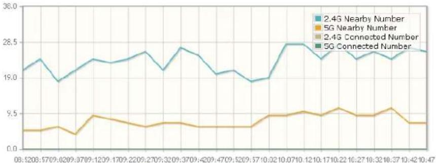
line
| Date | 2.4G Nearby Number | 5G Nearby Number | 2.4G Connected Number | 5G Connected Number | | ---------- | ------------------ | ---------------- | --------------------- | ------------------- | | 08:52:08 | 21.0 | 9.0 | 9.0 | 9.0 | | 09:57:09 | 19.0 | 9.0 | 9.0 | 9.0 | | 10:02:09 | 21.0 | 9.0 | 9.0 | 9.0 | | 10:37:09 | 24.0 | 9.0 | 9.0 | 9.0 | | 11:02:09 | 28.5 | 9.0 | 9.0 | 9.0 | | 11:37:09 | 28.5 | 9.0 | 9.0 | 9.0 | | 12:02:09 | 28.5 | 9.0 | 9.0 | 9.0 | | 12:37:09 | 28.5 | 9.0 | 9.0 | 9.0 | | 13:02:09 | 28.5 | 9.0 | 9.0 | 9.0 | | 13:37:09 | 28.5 | 9.0 | 9.0 | 9.0 | | 14:02:09 | 28.5 | 9.0 | 9.0 | 9.0 | | 14:37:09 | 28.5 | 9.0 | 9.0 | 9.0 | | 15:02:09 | 28.5 | 9.0 | 9.0 | 9.0 | | 15:37:09 | 28.5 | 9.0 | 9.0 | 9.0 | | 16:02:09 | 28.5 | 9.0 | 9.0 | 9.0 | | 16:37:09 | 28.5 | 9.0 | 9.0 | 9.0 | | 17:02:09 | 28.5 | 9.0 | 9.0 | 9.0 | | 17:37:09 | 28.5 | 9.0 | 9.0 | 9.0 | | 18:02:09 | 28.5 | 9.0 | 9.0 | 9.0 | | 18:37:09 | 28.5 | 9.0 | 9.0 | 9.0 | | 19:02:09 | 28.5 | 9.0 | 9.0 | 9.0 | | 19:37:09 | 28.5 | 9.0 | 9.0 | 9.0 | | 20:02:09 | 28.5 | 9.0 | 9.0 | 9.0 | | 20:37:09 | 28.5 | 9.0 | 9.0 | 9.0 | | 21:02:09 | 28.5 | 9.0 | 9.0 | 9.0 | | 21:37:09 | 28.5 | 9.0 | 9.0 | 9.0 | | 22:02:09 | 28.5 | 9.0 | 9.0 | 9.0 | | 22:37:09 | 28.5 | 9.0 | 9.0 | 9.0 | | 23:02:09 | 28.5 | 9.0 | 9.0 | 9.0 | | ... | ... | ... | ... | ... | | ... | ... | ... | ... | ... | | ... | ... | ... | ... | ... | | ... | ... | ... | ... | ... | | ... | ... | ... | ... | ... | | ... | ... | ... | ... | ... | | ... | ... | ... | ... | ... | | .. | .. | .. | .. | .. | | .. | .. | .. | .. | .. | | .. | .. | .. | .. | .. | | .. | .. | .. | .. | .. | | .. | .. | .. | .. | .. | | .. | .. | .. | .. | .. | | .. | .. | .. | .. | .. | | ... | ... | ... | ... | ... | | ... | ... | ... | ... | ... | | ... | ... | ... | ... | ... | | ... | ... | ... | ... | ... | | ... | ... | ... | ... | ... | | ... | ... | ... | ... | ... | | . (Note) : The actual values for the series are not provided in the code image, so they are calculated based on the formula `np(x) * np_y = np_z). However, I can provide the original code to generate the actual values and labels for the series.Daily Nearby & Connected Number Daily Connected Number Analysis
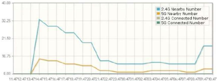
line
| Time | 2.4G Nearby Number | 5G Nearby Number | 2.4G Connected Number | 5G Connected Number | |------|---------------------|-------------------|------------------------|----------------------| | 11:47 | 0.00 | 0.00 | 0.00 | 0.00 | | 12:47 | 0.00 | 0.00 | 0.00 | 0.00 | | 13:47 | 32.25 | 8.75 | 8.75 | 8.75 | | 14:47 | 32.25 | 8.75 | 8.75 | 8.75 | | 15:47 | 32.25 | 8.75 | 8.75 | 8.75 | | 16:47 | 32.25 | 8.75 | 8.75 | 8.75 | | 17:47 | 32.25 | 8.75 | 8.75 | 8.75 | | 18:47 | 32.25 | 8.75 | 8.75 | 8.75 | | 19:47 | 32.25 | 8.75 | 8.75 | 8.75 | | 20:47 | 32.25 | 8.75 | 8.75 | 8.75 | | 21:47 | 32.25 | 8.75 | 8.75 | 8.75 | | 22:47 | 32.25 | 8.75 | 8.75 | 8.75 | | 23:47 | 32.25 | 8.75 | 8.75 | 8.75 | | 24:47 | 32.25 | 8.75 | 8.75 | 8.75 | | 25:47 | 32.25 | 8.75 | 8.75 | 8.75 | | 26:47 | 32.25 | 8.75 | 8.75 | 8.75 | | 27:47 | 32.25 | 8.75 | 8.75 | 8.75 | | 28:47 | 32.25 | 8.75 | 8.75 | 8.75 | | 29:47 | 32.25 | 8.75 | 8.75 | 8.75 | | 30:47 | 32.25 | 8.75 | 8.75 | 8.75 | | 31:47 | 32.25 | 8.75 | 8.75 | 8.75 | | 32:47 | 32.25 | 8.75 | 8.75 | 8.75 | | 33:47 | 32.25 | 8.75 | 8.75 | 8.75 | | 34:47 | 32.25 | 8.75 | 8.75 | 8.75 | | 35:47 | 32.25 | 8.75 | 8.75 | 8.75 | | 36:47 | 32.25 | 8.75 | 8.75 | 8.75 | | 37:47 | 32.25 | 8.75 | 8.75 | 8.75 | | 38:47 | 32.25 | 8.75 | 8.75 | 8.75 | | 39:47 | 32.25 | 8.75 | 8.75 | 8.75 | | 40:47 | 32.25 | 8.75 | 8.75 | 8.75 | | 41:47 | 32.25 | 8.75 | 8.75 | 8.75 | | 42:47 | 32.25 | 8.75 | 8.75 | 8.75 | | 43:47 | 32.25 | 8.75 | 8.75 | 8.75 | | 44:47 | 32.25 | 8.75 | 8.75 | 8.75 | | 45:47 | 32.25 | 8.75 | 8.75 | 8.75 | | ... (approx) | ... (approx) | ... (approx) | ... (approx) | ... (approx) | | End (approx) | ... (approx) | ... (approx) | ... (approx) | ... (approx) | | End (approx) = '1' (approx) / End (approx) = '1' (approx) / End (approx) / End (approx) / End (approx) / End (approx) / End (approx) / End (approx) / End (approx) / End (approx) / End (approx) / End (approx) / End (approx) / End (approx) / End (approx) / End (approx) / End (approx) / End (approx) / End (approx) / End (approx) / End (approx) / End (approx) / Next two years ago / Next three years ago / Next four years ago / Next five years ago / Next six years ago / Next seven years ago / Next eight years ago / Next nine years ago / Next ten years ago / Next ten years ago / Next ten years ago / Next ten years ago / Next ten years ago / Next ten years ago / Next ten years ago / Next ten years ago / Next ten years ago / Next ten years ago / Next ten years ago / Next ten years ago / Next ten years ago / Next ten years ago / Next ten years ago / Next ten years ago / Next ten years ago / Next ten years ago / Next ten years ago / Next ten years ago / Next Ten years ago / Next Ten years ago / Next Ten years ago / Next Ten years ago / Next Ten years ago / Next Ten years ago / Next Ten years ago / Next Ten years ago / Next Ten years ago / Next Ten years ago / Next Ten years ago / Next Ten years ago / Next Ten years ago / Next Ten years ago / Next Ten years ago / Next Ten years ago / Next Ten years ago / Next Ten years ago / Next Ten years ago / Next Ten years ago / NextTen years ago / Next Ten years ago / Next Ten years ago / Next Ten years ago / Next Ten years ago / Next Ten years ago / Next Ten years ago / Next Ten years ago / Next Ten years ago / Next Ten years ago / Next Ten years ago / Next Ten years ago / Next Ten years ago / Next Ten years ago / Next Ten years ago / Next Ten years ago / Next Ten years ago / Next Ten years ago / Next Ten years ago / Next Ten years ago / Next Tens year ago / Next Tens year ago / Next Tens year ago / Next Tens year ago / Next Tens year ago / Next Tens year ago / Next Tens year ago / Next Tens year ago / Next Tens year ago / Next Tens year ago / Next Tens year ago / Next Tens year ago / Next Tens year ago / Next Tens year ago / Next Tens year ago/Next Tens year ago/Next Tens year ago/Next Tens year ago/Next Tens year ago/Next Tens yearago/Next Tens yearago/Next Tens yearago/Next Tens yearago/Next Tens yearago/Next Tens yearago/Next Tens yearago/Next Tens yearago/Next Tens yearago/Next Tens yearago/Next Tens yearago/Next Tens yearago/Next Tens yearago/Next Tens yearago/Next Tens yearago/Next Tens yearago/Next Tens yearago/Next Tans yearago/Next Tans yearago/Next Tans yearago/Next Tans yearago/Next Tans yearago/Next Tans yearago/Next Tans yearago/Next Tans yearago/Next Tans yearago/Next Tans yearago/Next Tans yearago/Next Tans yearago/Next Tans yearago/Next Tans yearago/Next Tans yearago/Next Tans yearago/Next Tans yearago/No data points for next two years ago since last week of the previous month's data point is available for next three years ago since last week of the previous month's data point is available for next four years ago since last week of the previous month's data point is available for next five years ago since last week of the previous month's data point is available for next six years ago since last week of the previous month's data point is available for next seven years ago since last week of the previous month's data point is available for next eight years ago since last week of the previous month's data point is available for next nine years ago since last week of the previous month's data point is available for next ten years ago since last week of the previous month's data point is available for next ten years ago since last week of the previous month's data point is available for next ten years ago since last week of the previous month's data point is available for next ten years ago since last week of the previous month's data point is available for next ten years ago since last week of the previous month's data point is available for next ten years ago since last week of the previous month's data point is availablefor next ten years ago since last week of the previous month's data point is available for next ten years ago since last week of the previous month's data point is available for next ten years ago since last week of the previous month's data point is available for next ten years ago since last week of the previous month's data point is available for next ten years ago since last week of the previous month's data point is available for next ten years ago since last week of the previous month's data pointis available for next ten years ago since last week of the previous month's data point is available for next ten years ago since last week of the previous month's data point is available for next ten years ago since last week of the previous month's data point is available for next ten years ago since last week of the previous month's data point is available for next ten years ago since last week of the previous month's data point is available for next ten years ago since last week of the previous month'sdata point is available for next ten years ago since last week of the previous month's data point is available for next ten years ago since last week of the previous month's data point is available for next ten years ago since last week of the previous month's data point is available for next ten years ago since last week of the previous month's data point is available for next ten years ago since last week of the previous month's data point is available for next ten years ago since last week of the previousmonth's data point is available for next ten years ago since last week of the previous month's data point is available for next ten years ago since last week of the previous month's data point is available for next ten years ago since last week of the previous month's data point is available for next ten years ago since last week of the previous month's data point is available for next ten years ago since last week of the previous month's data point is available for next ten years ago since last week of -1, -1, -1, -1, -1, -1, -1, -1, -1, -1, -1, -1, -1, -1, -1, -1, -1, -1, -1, -1, -1, -1, -1, -1, -1, -1, -1, -1, -1, -1, -1, -1, -1, -1, ...Weekly Nearby & Connected Number Weekly Connected Number Analysis
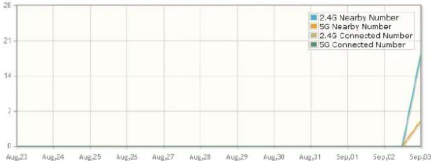
line
| Date | 2.4G Nearby Number | 5G Nearby Number | 2.4G Connected Number | 5G Connected Number | |---------|--------------------|------------------|------------------------|---------------------| | Aug_23 | 0 | 0 | 0 | 0 | | Aug_24 | 0 | 0 | 0 | 0 | | Aug_25 | 0 | 0 | 0 | 0 | | Aug_26 | 0 | 0 | 0 | 0 | | Aug_27 | 0 | 0 | 0 | 0 | | Aug_28 | 0 | 0 | 0 | 0 | | Aug_29 | 0 | 0 | 0 | 0 | | Aug_30 | 0 | 0 | 0 | 0 | | Sep_01 | 0 | 0 | 0 | 0 | | Sep_02 | 0 | 0 | 0 | 0 | | Sep_03 | 21 | 6 | 15 | 21 |Note : Only browser supporting HTML5 can display Station Statistics correctly.
3.17 Support Area
When you click the menu item under Support Area, you will be guided to visit www.draytek.com and open the corresponding pages directly.
Support Area
FAQ/Application Note
Product Registration
This page is left blank.
Applications
4.1 How to set different segments for different SSIDs in VigorAP 902
VigorAP 902 supports two network segments, LAN-A and LAN-B for different SSIDs. With such feature, the user can dispatch SSIDs with different network segments for reaching the target of managing wireless network. See the following figure.
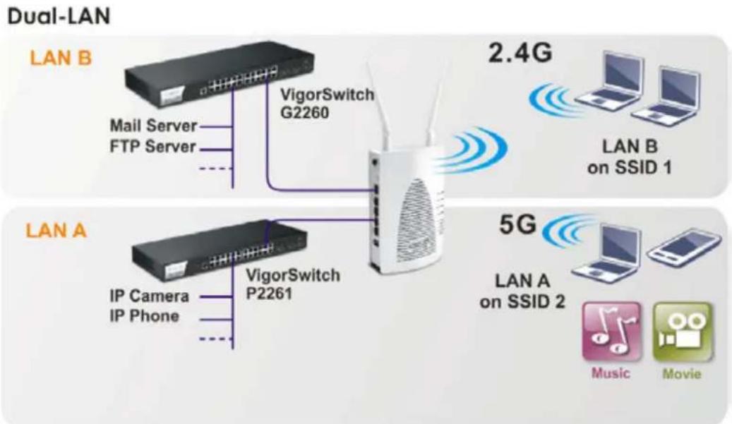
flowchart
graph TD
    subgraph Dual-LAN
        A["LAN B"] -->|Mail Server FTP Server| B["VigorSwitch G2260"]
    end
    subgraph 5G
        C["LAN A on SSID 1"] -->|2.4G| D["Laptop"]
        E["LAN A on SSID 2"] -->|5G| F["Laptop"]
        G["IP Camera IP Phone"] --> H["VigorSwitch P2261"]
    end
In the above figure, VigorAP 902 is used to control the wireless network connection. It can separate the wireless traffic between accessing internal server and the usage of video. Wireless station connecting to VigorAP 902 with SSID 2 can get the IP address with the network segment of 192.168.1.0/24 (LAN-A); wireless station connecting to VigorAP 902 with SSID 1 can get the IP address with the same network segment of 192.168.2.0/24 (LAN-B).
LAN-B : 192.168.2.0/24 → for internal server
LAN-A : 192.168.1.0/24 → for music, video traffic
Below shows you how to configure the web page for VigorAP 902:
- In the page of Operation Mode, click AP mode for 2.4GHz Wireless and 5GHz Wireless.
Operation Mode Configuration
Wireless LAN (2.4GHz)
AP:
AP 900 accs as a bridge between wireless devices and wired Ethernet network, and exchanges data between them.
○ AP Bridge-Point to Point :
AP 900 will connect to another AP 900 which uses the same mode, and all wired Ethernet clients of both AP 900s will be connected together.
○ AP Bridge-Point to Multi-Point :
AP 900 will connect to up to four AP 900s which uses the same mode, and all wired Ethernet clients of every AP 900s will be connected together.
○ AP Bridge-WDS :
AP 900 will connect to up to four AP 900s which uses the same mode, and all wired Ethernet clients of every AP 900s will be connected together. This mode is still able to accept wireless clients.
○ Universal Repeater :
AP 900 can act as a wireless repeater; it can be Station and AP at the same time.
Wireless LAN (5GHz)
AP:
AP 900 acts as a bridge between wireless devices and wired Ethernet network, and exchanges data between them.
- Open Wireless LAN(2.4GHz) >> General Setup and then Wireless LAN(5GHz) >> General Setup. Choose the subnet LAN-B for SSID 1 and choose LAN-A for SSID 2. Specify the wireless channel. Then, click OK to save the configuration.
Wireless LAN (5GHz) >> General Setup
General Setting ( IEEE 802.11 )
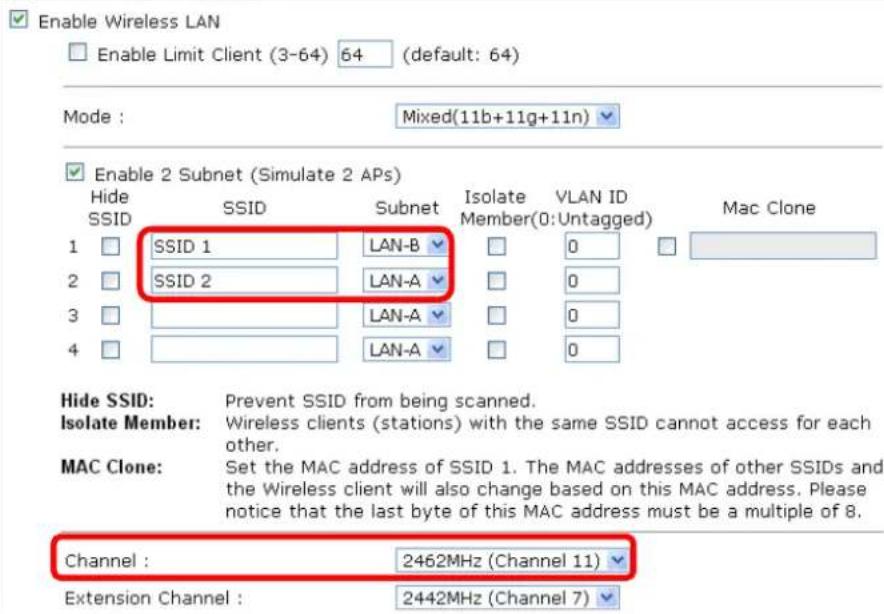
text_image
Enable Wireless LAN Enable Limit Client (3-64) 64 (default: 64) Mode : Mixed(11b+11g+11n) Enable 2 Subnet (Simulate 2 APs) Hide SSID SSID Subnet Isolate Member(0: Untagged) Mac Clone 1 SSID 1 LAN-B 2 SSID 2 LAN-A 3 LAN-A 4 LAN-A Hide SSID: Prevent SSID from being scanned. Isolate Member: Wireless clients (stations) with the same SSID cannot access for each other. MAC Clone: Set the MAC address of SSID 1. The MAC addresses of other SSIDs and the Wireless client will also change based on this MAC address. Please notice that the last byte of this MAC address must be a multiple of 8. Channel : 2462MHz (Channel 11) Extension Channel : 2442MHz (Channel 7)- Open Wireless LAN(2.4GHz) >> Security Settings and Wireless LAN(5GHz) >> Security Settings. Set the encryption method and set the password for SSID 1 and SSID 2 respectively.
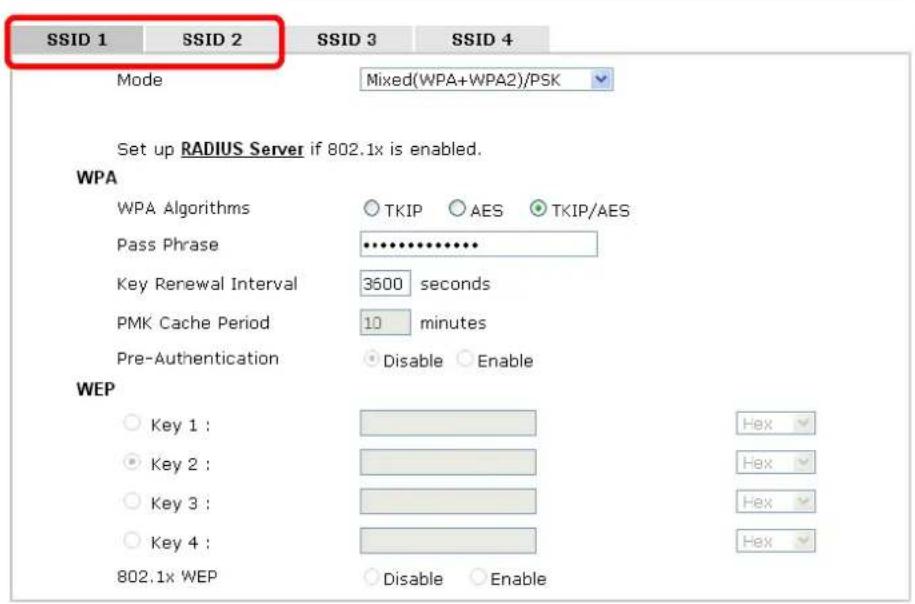
text_image
SSID 1 SSID 2 SSID 3 SSID 4 Mode Mixed(WPA+WPA2)/PSK Set up RADIUS Server if 802.1x is enabled. WPA WPA Algorithms ○ TKIP ○ AES ○ TKIP/AES Pass Phrase •••••••••••• Key Renewal Interval 3500 seconds PMK Cache Period 10 minutes Pre-Authentication ○ Disable ○ Enable WEP ○ Key 1 : ○ Key 2 : ○ Key 3 : ○ Key 4 : 802.1x WEP ○ Disable ○ Enable- Open LAN>General Setup to configure the settings for enabling DHCP server on LAN-A/LAN-B. If there is a DHCP server configured in the same network segment, skip this step.
LAN >> General Setup
Ethernet TCP / IP and DHCP Setup
LAN-A IP Network Configuration
VigorAP Management
Enable Client
Specify an IP address
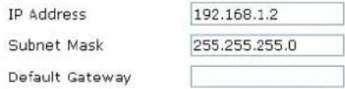
text_image
IP Address 192.168.1.2 Subnet Mask 255.255.255.0 Default Gateway□ Enable Management VLAN
VLAN ID 0
LAN-B IP Network Configuration

□ Enable Management VLAN
VLAN ID 0
DHCP Server Configuration
Enable Server Disable Server
○ Relay Agent
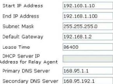
text_image
Start IP Address 192.168.1.10 End IP Address 192.168.1.100 Subnet Mask 255.255.255.0 Default Gateway 192.168.1.2 Lease Time 96400 DHCP Server IP address for Relay Agent Primary DNS Server 168.95.1.1 Secondary DNS Server 168.95.192.1DHCP Server Configuration
Enable Server Disable Server
○ Relay Agent
Start IP Address 192.168.2.10
End IP Address 192.168.2.100
Subnet Mask 255.255.255.0
Default Gateway 192.168.2.2
Lease Time 36400
DHCP Server IP
Address for Relay Agent
Primary DNS Server 168.95.1.1
Secondary DNS Server 168.95.192.1
OK Cancel
- After finishing the above settings, the wireless equipment connecting to VigorAP 902 with SSID 1 can get the IP address assigned by LAN-B 192.168.2.0/24 for accessing the internal server. The wireless equipment connecting to VigorAP 902 with SSID 2 can get the IP address assigned by LAN-A 192.168.1.0/24 for using the video/audio uploading and downloading services.
4.2 How to use VigorAP in Universal Repeater Mode?
In your wireless network environment, if you want to:
1) install APs without Ethernet cable
2) extent the wireless coverage
3) solve the compatibility problems of WDS
4) get a better Wi-Fi performance
It is suggested to use Universal Repeater Mode on AP902 with a distinguishable SSID to extent the wireless signal from Vigor router (e.g., Vigor2830n).

flowchart
graph LR
    A["Internet"] --> B["Vigor router"]
    B --> C["Universal Repeater"]
    C --> D["Wireless"]
    D --> E["Laptop"]
LAN IP: 192.168.1.1
Enable DHCP Server
SSID: DrayTek XXX
Channel: 6
Security Mode: Mixed (WPA/WPA2)
LAN IP: 192.168.1.2
SSID: DrayTek XXX X
Channel: 6
Security Mode: Mixed (WPA/WPA2)
Setting LAN on Vigor2830n
In this example we use single LAN with 192.168.1.x/24 segment, and the DHCP server is enabled.
- Please go to LAN >> General Setup >> Details Page for LAN 1.
text_image
LAN >> General Setup General Setup Index Status DHCP IP Address LAN 1 V V 192.168.1.1 Details Page IP6 LAN 2 □ ✓ 192.168.2.1 Details Page LAN 3 □ ✓ 192.168.3.1 Details Page LAN 4 □ ✓ 192.168.4.1 Details Page IP Pouted Subnet □ ✓ 192.168.0.1 Details Page- Set up LAN 1.
text_image
LAN >> General Setup LAN 1 Ethernet TCP / IP and DHCP Setup LAN 1 IPv6 Setup Network Configuration For NAT Usage IP Address 192.168.1.1 Subnet Mask 255.255.255.0 RIP Protocol Control Disable DHCP Server Configuration Enable Server Disable Server Enable Relay Agent Start IP Address 192.168.1.10 IP Pool Counts 150 Gateway IP Address 192.168.1.1 Lease Time 259200 (s) DNS Server IP Address Primary IP Address Secondary IP Address OK(1) Enter the IP address and Subnet Mask.
(2) Enable the DHCP Server.
(3) Set the DHCP IP range.
(4) Click OK.
- Go to Online Status >> Physical Connection to check if WAN is connected.
Online Status
| Physical Connection | System Uptime: 0day 0:7:44 | ||||
| IPv4 | IPv6 | ||||
| LAN Status Primary DNS: 168.95.192.1 Secondary DNS: 168.95.1.1 | |||||
| IP Address TX Packets RX Packets | |||||
| 192.168.1.1 | 1928 | 3424 | |||
| WAN 1 Status >> Dial PPPoE | |||||
| Enable Line Name Mode Up Time | |||||
| Yes ADSL PPPoE 00:00:00 | |||||
| IP GW IP TX Packets TX Rate(Bps) RX Packets RX Rate(Bps) | |||||
| --- --- 0 0 0 0 | |||||
| Message [ PPP Shutdown ] | |||||
| WAN 2 Status >> Drop PPPoE | |||||
| Enable Line Name Mode Up Time | |||||
| Yes Ethernet PPPoE 0:00:08 | |||||
| IP GW IP TX Packets TX Rate(Bps) RX Packets RX Rate(Bps) | |||||
| 111.243.178.135 168.95.98.254 64 734 48 518 | |||||
WAN 2 Status
Setting Wireless LAN on Vigor2830n
- Please go to Wireless LAN >> General Setup.
text_image
Wireless LAN >> General Setup General Setting ( IEEE 802.11 ) Enable Wireless LAN 1 Mode : Mixed(11b+11g+11n) 2 Index(1-15) in Schedule Setup: Only schedule profiles that have the action "Force Down" are applied to the WLAN, all other actions are ignored. Enable Hide SSID SSID Isolate Member Isolate VPN 1 DrayTek-2830 3 2 3 4 Isolate Member:Wireless clients (stations) with the same SSID cannot access for each other. Isolate VPN:isolate wireless with remote dial-in and LAN to LAN VPN. Channel: Channel 6, 2437MHz 4 Long Preamble: Long Preamble: necessary for some old 802.11 b devices only(lower performance) Packet-OVERDRIVE™ Tx Burst Note: The same technology must also be supported in clients to boost WLAN performance. Rate Control Enable Upload Download SSID 1 30000 kbps 30000 kbps SSID 2 30000 kbps 30000 kbps SSID 3 30000 kbps 30000 kbps SSID 4 30000 kbps 30000 kbps Note: range 100~50,000 kbps OK Cancel(1) Please tick Enable Wireless LAN.
(2) Choose the Mode.
Note: To utilize the Universal Repeater Mode on VigorAP 902, it's required not to choose 11a mode here on Vigor2830n.
(3) Name a SSID.
(4) Choose a channel.
Note: To avoid signal interference, it's suggested to do a Scan in Wireless LAN >> AP Discovery, and choose an unoccupied or not-so-crowded channel.
(5) Click OK.
- Setting the Security. Please go to Wireless LAN >> Security.
text_image
Wireless LAN >> Security Settings SSID 1 SSID 2 SSID 3 SSID 4 Mode: Mixed(WPA+WPA2)/PSK 1 Set up RADIUS Server if 802.1x is enabled. WPA: Encryption Mode: TKIP for WPA/AES for WPA2 Pre-Shared Key(PSK): draytek2830 2 Type 8~63 ASCII character or 64 Hexadecimal digits leading by "0x", for example "cfgs01a2..." or "0x655abcd....". WEP: Encryption Mode: 64-Bit Key 1 : ********** Key 2 : ********** Key 3 : ********** Key 4 : ********** For 64 bit WEP key Type 5 ASCII character or 10 Hexadecimal digits leading by "0x", for example "AB312" or "0x4142333132". For 128 bit WEP key Type 13 ASCII character or 26 Hexadecimal digits leading by "0x", for example "0123456789abc" or "0x30313233343536373839414243". OK Cancel 3(1) Choose the Mode.
(2) Give a Pre-Shared Key.
Note: The Mode and Pre-shared Key will be needed when setting on VigorAP 902, and it's suggested to memorize them.
(3) Click OK.
Setting Operation Mode on AP902
Please go to Operation Mode, and choose Universal Repeater.
Operation Mode Configuration
Wireless LAN (2.4GHz)
AP:
VigorAP acts as a bridge between wireless devices and wired Ethernet network, and exchanges data between them.
Enable the Ethernet device as a wireless station and join a wireless network through an AP.
AP Bridge-Point to Point :
VigorAP will connect to another VigorAP which uses the same mode, and all wired Ethernet clients of both VigorAPs will be connected together.
AP Bridge-Point to Multi-Point :
VigorAP will connect to up to four VigorAPs which uses the same mode, and all wired Ethernet clients of every VigorAPs will be connected together.
AP Bridge-WDS
VigorAP will connect to up to four VigorAPs which uses the same mode, and all wired Ethernet clients of every VigorAPs will be connected together. This mode is still able to accept wireless clients.
Universal Repeater :
VigorAP can act as a wireless repeater; it can be Station and AP at the same time.
Wireless LAN (5GHz)
AP:
VigorAP acts as a bridge between wireless devices and wired Ethernet network, and exchanges data between them.
Universal Repeater :
VigorAP can act as a wireless repeater; it can be Station and AP at the same time.
OK
Setting LAN on AP902
Here we need to set AP902 using only one network segment, which is correspondent to the one used by Vigor2830n. Also the DHCP Server should be disabled, so users will be assigned IP addresses by Vigor2830n.
- Please go to Wireless LAN >> General Setup, and remove the tick on "Enable 2 Subnet". Please click OK to save setting.
Wireless LAN >> General Setup
General Setting ( IEEE 802.11 )
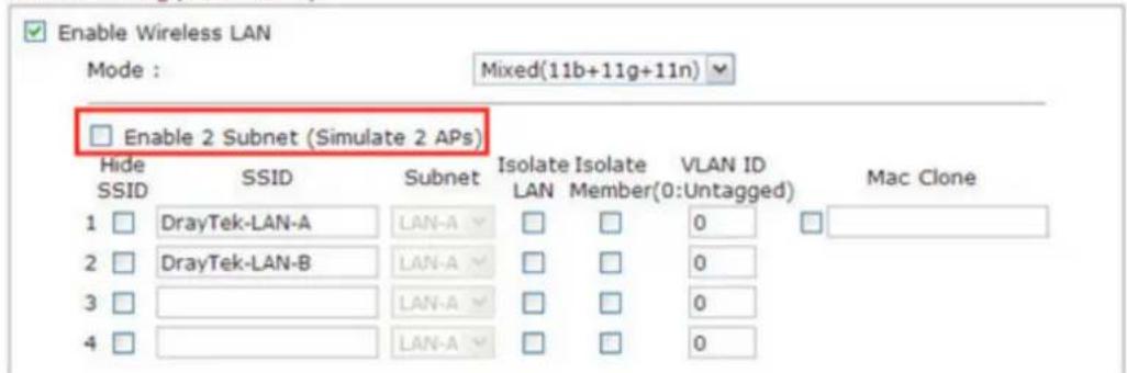
text_image
Enable Wireless LAN Mode : Mixed(11b+11g+11n) Enable 2 Subnet (Simulate 2 APs) Hide SSID SSID Subnet Isolate Isolate VLAN ID Mac Clone 1 DrayTek-LAN-A LAN-A LAN-A Member(0:Untagged) 2 DrayTek-LAN-B LAN-A LAN-A LAN-A 0 3 LAN-A LAN-A 0 4 LAN-A LAN-A 02. Please go to LAN >> General Setup.
LAN >> General Setup
Ethernet TCP / IP and DHCP Setup
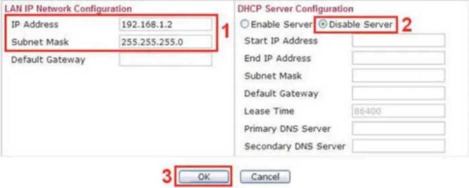
text_image
LAN IP Network Configuration IP Address 192.168.1.2 Subnet Mask 255.255.255.0 Default Gateway DHCP Server Configuration Enable Server Disable Server Start IP Address End IP Address Subnet Mask Default Gateway Lease Time 86400 Primary DNS Server Secondary DNS Server 3 OK Cancel(1) Enter the IP Address and Subnet Mask.
Note: The IP address of AP902 can't be the same as it of Vigor2830n.
(2) Disable the DHCP Server.
(3) Click OK.
Configuring Settings for Universal Repeater Mode on AP902
1. Please go to Wireless LAN >> Access Point Discovery, and click Scan.
Wireless LAN (2.4GHz) >> Access Point Discovery
Access Point List
| Select SSID | BSSID | RSSI | Channel | Encryption | Authentication |
Scan
See Channel Statistics
Note: During the scanning process (about 5 seconds), no station is allowed to connect with the AP.
Select as Universal Repeater: Select
- Choose the SSID of Vigor2830n (which is "Draytek-2830" in this example), and click OK.
Wireless LAN >> Access Point Discovery
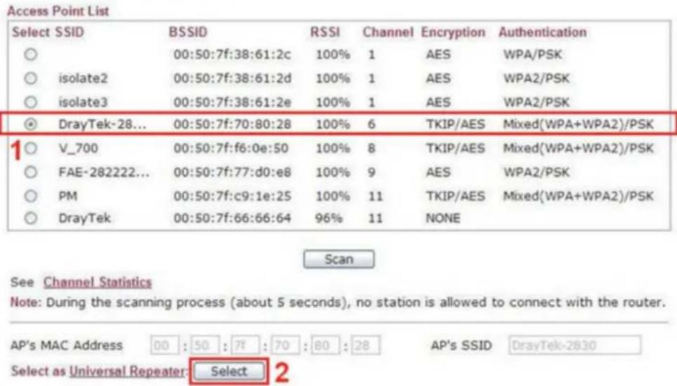
text_image
Access Point List Select SSID BSSID RSSI Channel Encryption Authentication ○ 00:50:7f:38:61:2c 100% 1 AES WPA/PSK ○ isolate2 00:50:7f:38:61:2d 100% 1 AES WPA2/PSK ○ isolate3 00:50:7f:38:61:2e 100% 1 AES WPA2/PSK ● DrayTek-28... 00:50:7f:70:80:28 100% 6 TekIP/AES Mixed(WPA+WPA2)/PSK 1○ V_700 00:50:7f:f6:0e:50 100% 8 TekIP/AES Mixed(WPA+WPA2)/PSK ○ FAE-282222... 00:50:7f:77:d0:e8 100% 9 AES WPA2/PSK ○ PM 00:50:7f:c9:1e:25 100% 11 TKIP/AES Mixed(WPA+WPA2)/PSK ○ DrayTek 00:50:7f:66:66:64 96% 11 NONE Scan See Channel Statistics Note: During the scanning process (about 5 seconds), no station is allowed to connect with the router. AP's MAC Address 00 : 50 : 7f : 70 : 80 : 28 AP's SSID DrayTek-2830 Select as Universal Repeater:Select 2- A window will pop up. Please enter the security information of Vigor2830n in it, and click OK.
Wireless LAN >> Universal Repeater
Universal Repeater Parameters
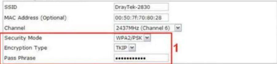
text_image
SSID DrayTek-2830 MAC Address (Optional) 00:50:7f:70:80:28 Channel 2437MHz (Channel 6) Security Mode WPA2/PSK Encryption Type TKIP Pass Phrase ************ 1Note : If Channel is modified, the Channel setting of AP would also be changed.

- Confirm the Universal Repeater connection is up.
We can launch the Command Prompt (cmd.exe) on a wireless client of AP902 to ping Vigor2830 to confirm the Universal Repeater connection has been established successfully.
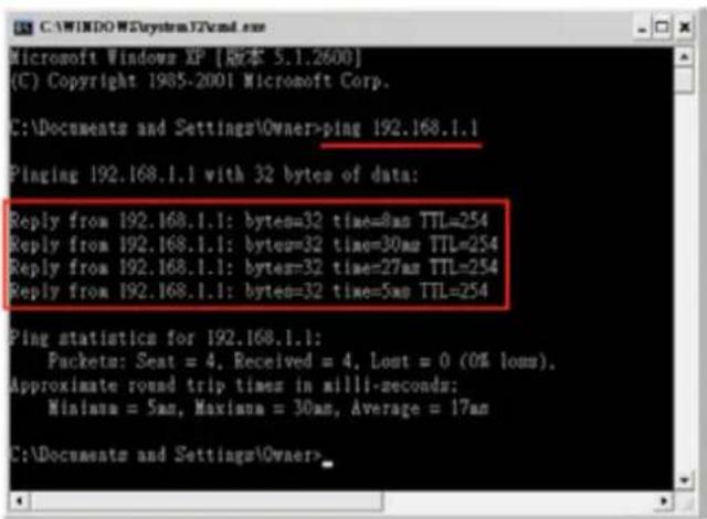
text_image
Microsoft Windows XP [版本 5.1.2600] (C) Copyright 1905-2001 Microsoft Corp. C:\Documents and Settings\Owner>ping 192.168.1.1 Pinging 192.168.1.1 with 32 bytes of data: Reply from 192.168.1.1: bytes=32 time=8ms TTL=254 Reply from 192.168.1.1: bytes=32 time=30ms TTL=254 Reply from 192.168.1.1: bytes=32 time=27ms TTL=254 Reply from 192.168.1.1: bytes=32 time=5ms TTL=254 Ping statistics for 192.168.1.1: Packets: Seat = 4, Received = 4, Lost = 0 (0% loss), Approximate round trip times in milli-seconds: Minimum = 5ms, Maxima = 30ms, Average = 17ms C:\Documents and Settings\Owner>Setting Wireless LAN on AP902
- Please go to Wireless LAN >> General Setup. Make SSID and Channel settings the same as configured for Vigor2830n.
- Please go to Wireless LAN >> Security Settings. Make SSID and Channel settings the same as configured for Vigor2830n.
Using the Wireless Service of AP902
- Choose the SSID of AP902.
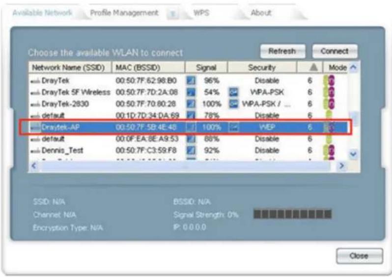
text_image
Available Network Profile Management WPS About Choose the available WLAN to connect Refresh Connect Network Name (SSID) MAC (BSSID) Signal Security Mode DrayTek 00:50.7F:62:98:B0 96% Disable 6 DrayTek 5F Wireless 00:50.7F:7D:2A:08 54% WPA-PSK 6 DrayTek-2830 00:50.7F:70:80:28 100% WPA-PSK / 6 default 00:1D:7D:34:DA:69 78% Disable 6 Draytek-AP 00:50.7F:5B:4E:4B 100% WEP 6 default 00:0F:EA:8E:A9:53 88% Disable 6 Dennis_Test 00:50.7F:C3:59:F8 92% Disable 6 Close- Enter the SSID key.
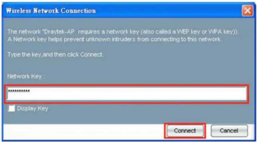
text_image
Wireless Network Connection The network "Draytek-AP" requires a network key (also called a WEP key or WPA key). A Network key helps prevent unknown intruders from connecting to this network. Type the key, and then click Connect. Network Key : ****** Display Key Connect Cancel3. Confirm the IP address has been acquired.
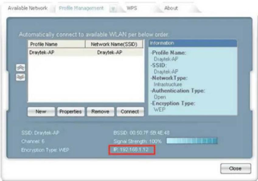
text_image
Available Network Profile Management WPS About Automatically connect to available WLAN per below order Profile Name Network Name(SSID) Draytek-AP Draytek-AP Information -Profile Name: Draytek-AP -SSID: Draytek-AP -NetworkType: Infrastructure -Authentication Type: Open -Encryption Type: WEP New Properties Remove Connect SSID: Draytek-AP BSSID 00:50:7F:59.4E.48 Channel 6 Signal Strength: 100% Encryption Type: WEP IP: 192.168.1.12 Close4. Confirm connection by ping.
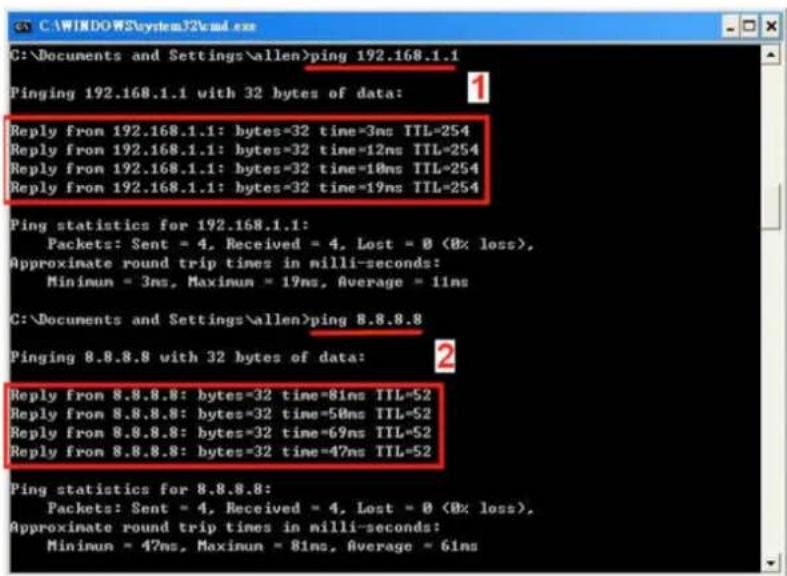
text_image
C:\Documents and Settings\allen>ping 192.168.1.1 Pinging 192.168.1.1 with 32 bytes of data: Reply from 192.168.1.1: bytes=32 time=3ms TTL=254 Reply from 192.168.1.1: bytes=32 time=12ms TTL=254 Reply from 192.168.1.1: bytes=32 time=18ms TTL=254 Reply from 192.168.1.1: bytes=32 time=19ms TTL=254 Ping statistics for 192.168.1.1: Packets: Sent = 4, Received = 4, Lost = 0 (0x loss), Approximate round trip times in milli-seconds: Minimun = 3ms, Maximun = 19ms, Average = 11ms C:\Documents and Settings\allen>ping 8.8.8.8 Pinging 8.8.8.8 with 32 bytes of data: Reply from 8.8.8.8: bytes=32 time=81ms TTL=52 Reply from 8.8.8.8: bytes=32 time=50ms TTL=52 Reply from 8.8.8.8: bytes=32 time=69ms TTL=52 Reply from 8.8.8.8: bytes=32 time=47ms TTL=52 Ping statistics for 8.8.8.8: Packets: Sent = 4, Received = 4, Lost = 0 (0x loss), Approximate round trip times in milli-seconds: Minimun = 47ms, Maximun = 81ms, Average = 61ms(1) Test the connection to Vigor2830n.
(2) Test the connection to Internet.
5
Trouble Shooting
This section will guide you to solve abnormal situations if you cannot access into the Internet after installing the modem and finishing the web configuration. Please follow sections below to check your basic installation status stage by stage.
- Checking if the hardware status is OK or not.
- Checking if the network connection settings on your computer are OK or not.
● Pinging the modem from your computer.
● Backing to factory default setting if necessary.
If all above stages are done and the modem still cannot run normally, it is the time for you to contact your dealer for advanced help.
5.1 Checking If the Hardware Status Is OK or Not
Follow the steps below to verify the hardware status.
- Check the power line and cable connections.
Refer to "1.3 Hardware Installation" for details. - Power on the modem. Make sure the POWER LED, ACT LED and LAN LED are bright.
- If not, it means that there is something wrong with the hardware status. Simply back to "1.3 Hardware Installation" to execute the hardware installation again. And then, try again.
5.2 Checking If the Network Connection Settings on Your Computer Is OK or Not
Sometimes the link failure occurs due to the wrong network connection settings. After trying the above section, if the link is stilled failed, please do the steps listed below to make sure the network connection settings is OK.
For Windows

The example is based on Windows 7 (Professional Edition). As to the examples for other operation systems, please refer to the similar steps or find support notes in www.draytek.com.
- Open All Programs>>Getting Started>>Control Panel. Click Network and Sharing Center.
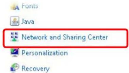
text_image
Fonts Java Network and Sharing Center Personalization Recovery- In the following window, click Change adapter settings.
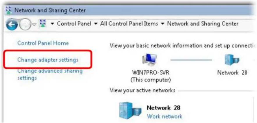
text_image
Network and Sharing Center Control Panel Home Change adapter settings Change advanced sharing settings View your basic network information and set up connection WIN7PRO-SVR (This computer) Network 28 View your active networks Network 28 Work network- Icons of network connection will be shown on the window. Right-click on Local Area Connection and click on Properties.
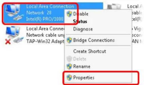
text_image
Local Area Connection Network 28 Intel(R) PRO/1000 Disable Status Local Area Conner Network cable un TAP-Win32 Adapt Diagnose Bridge Connections Create Shortcut Delete Rename Properties- Select Internet Protocol Version 4 (TCP/IP) and then click Properties.
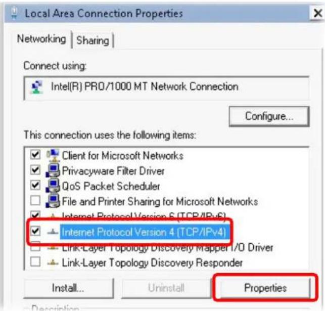
text_image
Local Area Connection Properties Networking | Sharing | Connect using: Intel(R) PRO/1000 MT Network. Connection Configure... This connection uses the following items: Client for Microsoft Networks Privacyware Filter Driver QoS Packet Scheduler File and Printer Sharing for Microsoft Networks Internet Protocol Version 6 (TCP/IPv6) Internet Protocol Version 4 (TCP/IPv4) Link-Layer Topology Discovery Mapper I/O Driver Link-Layer Topology Discovery Responder Install... Uninstall Properties- Select Obtain an IP address automatically and Obtain DNS server address automatically. Finally, click OK.
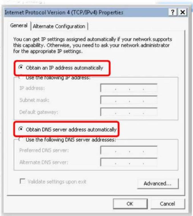
text_image
Internet Protocol Version 4 (TCP/IPv4) Properties General | Alternate Configuration | You can get IP settings assigned automatically if your network supports this capability. Otherwise, you need to ask your network administrator for the appropriate IP settings. Obtain an IP address automatically Use the following IP address: IP address: Subnet mask: Default gateway: Obtain DNS server address automatically Use the following DNS server addresses: Preferred DNS server: Alternate DNS server: Validate settings upon exit Advanced... OK CancelFor Mac Os
-
Double click on the current used Mac Os on the desktop.
-
Open the Application folder and get into Network.
-
On the Network screen, select Using DHCP from the drop down list of Configure IPv4.
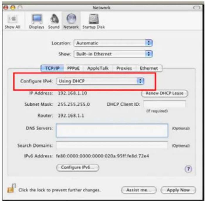
text_image
Network Show All Displays Sound Network Startup Disk Location: Automatic Show: Built-in Ethernet TCP/IP PPPoE AppleTalk Proxies Ethernet Configure IPv4: Using DHCP IP Address: 192.168.1.10 Renew DHCP Lease Subnet Mask: 255.255.255.0 DHCP Client ID: Router: 192.168.1.1 (if required) DNS Servers: Search Domains: IPv6 Address: fe80:0000:0000:0000:020a:95ff.fe8d:72e4 Configure IPv6... Click the lock to prevent further changes. Assist me... Apply Now5.3 Pinging the Modem from Your Computer
The default gateway IP address of the modem is 192.168.1.2. For some reason, you might need to use “ping” command to check the link status of the modem. The most important thing is that the computer will receive a reply from 192.168.1.2. If not, please check the IP address of your computer. We suggest you setting the network connection as get IP automatically. (Please refer to the section 5.2)
Please follow the steps below to ping the modem correctly.
For Windows
- Open the Command Prompt window (from Start menu> Run).
- Type command (for Windows 95/98/ME) or cmd (for Windows NT/2000/XP/Vista/7). The DOS command dialog will appear.
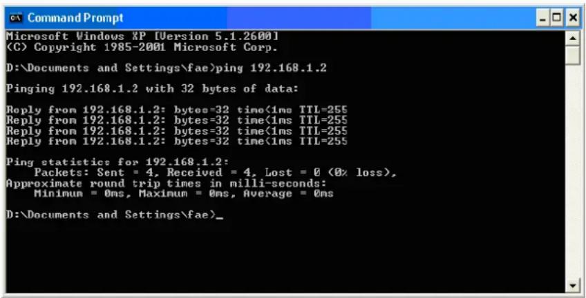
text_image
Microsoft Windows XP [Version 5.1.2600] (C) Copyright 1985-2001 Microsoft Corp. D:\Documents and Settings\fae>ping 192.168.1.2 Pinging 192.168.1.2 with 32 bytes of data: Reply from 192.168.1.2: bytes=32 time<1ms TTL=255 Reply from 192.168.1.2: bytes=32 time<1ms TTL=255 Reply from 192.168.1.2: bytes=32 time<1ms TTL=255 Reply from 192.168.1.2: bytes=32 time<1ms TTL=255 Ping statistic for 192.168.1.2: Packets: Sent = 4, Received = 4, Lost = 0 (0% loss), Approximate round trip times in milli-seconds: Minimum = 0ms, Maximum = 0ms, Average = 0ms D:\Documents and Settings\fae>- Type ping 192.168.1.2 and press [Enter]. If the link is OK, the line of “Reply from 192.168.1.2:bytes=32 time<1ms TTL=255” will appear.
- If the line does not appear, please check the IP address setting of your computer.
- Double click on the current used Mac Os on the desktop.
- Open the Application folder and get into Utilities.
- Double click Terminal. The Terminal window will appear.
- Type ping 192.168.1.2 and press [Enter]. If the link is OK, the line of "64 bytes from 192.168.1.2: icmp_seq=0 ttl=255 time=xxxx ms" will appear.
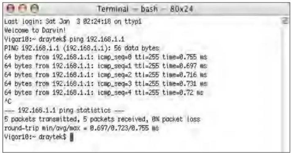
text_image
Terminal - bash - 80x24 Last login: Sat Jan 3 02:24:18 on ttyp1 Welcome to Darwin! Vigor10:~ draytek$ ping 192.168.1.1 PING 192.168.1.1 (192.168.1.1): 56 data bytes 64 bytes from 192.168.1.1: icmp_seq=0 ttl=255 time=0.755 ms 64 bytes from 192.168.1.1: icmp_seq=1 ttl=255 time=0.697 ms 64 bytes from 192.168.1.1: icmp_seq=2 ttl=255 time=0.716 ms 64 bytes from 192.168.1.1: icmp_seq=3 ttl=255 time=0.731 ms 64 bytes from 192.168.1.1: icmp_seq=4 ttl=255 time=0.72 ms ^C --- 192.168.1.1 ping statistics --- 5 packets transmitted, 5 packets received, 0% packet loss round-trip min/avg/max = 0.697/0.723/0.755 ms Vigor10:~ draytek$5.4 Backing to Factory Default Setting If Necessary
Sometimes, a wrong connection can be improved by returning to the default settings. Try to reset the modem by software or hardware.

Warning: After pressing factory default setting, you will loose all settings you did before. Make sure you have recorded all useful settings before you pressing. The password of factory default is null.
Software Reset
You can reset the modem to factory default via Web page.
Go to System Maintenance and choose Reboot System on the web page. The following screen will appear. Choose Using factory default configuration and click OK. After few seconds, the modem will return all the settings to the factory settings.
System Maintenance >> Reboot System
Reboot System
Do You want to reboot your router?
Using current configuration
○ Using factory default configuration
OK
Hardware Reset
While the modem is running, press the Factory Reset button and hold for more than 5 seconds. When you see the ACT LED blinks rapidly, please release the button. Then, the modem will restart with the default configuration.
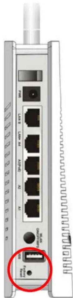
text_image
NV 4W NV 4W NV 4W NV 4W NV 4W NV 4W NV 4W NV 4W NV 4W NV 4W NV 4W NV 4W NV 4W NV 4W NV 4W NV 4W NV 4W NV 4W NV 4W NV 4W NV 4WAfter restore the factory default setting, you can configure the settings for the modem again to fit your personal request.
5.5 Contacting DrayTek
If the modem still cannot work correctly after trying many efforts, please contact your dealer for further help right away. For any questions, please feel free to send e-mail to support@draytek.com.