
9000PD - Projector 3M - Free user manual and instructions
Find the device manual for free 9000PD 3M in PDF.


| Product Type | Video Projector |
| Brand | 3M |
| Model | 9000PD |
| Display Technology | LCD |
| Native Resolution | XGA (1024 x 768) |
| Brightness | 2500 ANSI Lumens |
| Contrast Ratio | 2000:1 |
| Lamp Type | UHP 200W |
| Lamp Life (Normal Mode) | 2000 hours |
| Lamp Life (Eco Mode) | 3000 hours |
| Dimensions (W x D x H) | 330 x 250 x 110 mm |
| Weight | 3.5 kg |
| Power Consumption | 250W (Standby: <1W) |
| Input Voltage | AC 100-240V, 50/60Hz |
| Connectivity Inputs | VGA, Composite Video, S-Video, Audio 3.5mm |
| Connectivity Outputs | Monitor Out (VGA), Audio Out |
| Keystone Correction | Vertical ±15° |
| Zoom Ratio | 1.2x Manual |
| Built-in Speaker | 1 x 2W |
| Fan Noise | 35 dB (Normal Mode) |
| Maintenance | Clean air filter every 100 hours; replace lamp as needed |
| Safety Features | Auto-off after inactivity, overheat protection |
| Included Accessories | Power cable, VGA cable, remote control, user manual |
| Repair/Spare Parts Availability | Lamp module, filters available from 3M service centers |
Frequently Asked Questions - 9000PD 3M
User questions about 9000PD 3M
0 question about this device. Answer the ones you know or ask your own.
Ask a new question about this device
Download the instructions for your Projector in PDF format for free! Find your manual 9000PD - 3M and take your electronic device back in hand. On this page are published all the documents necessary for the use of your device. 9000PD by 3M.
USER MANUAL 9000PD 3M
natural_image
Modern digital scanner with transparent screen and illuminated modules against a blue gradient background (no text or symbols visible)February 2005
78-6970-9380-1 Rev. B
Copyright © 2004, 3M.
All Rights Reserved.
(This page intentionally left blank for printed version)
Contents
Introduction
Thank You for Choosing 3M....5
Safety Information....5
Intended Use 5
Product Safety Label 9
Save These Instructions 9
Trademarks 9
Patents 10
3M Digital WallDisplay Technical Support....10
FCC Statement—Class A 10
EEC Statement—Class A 10
Model Identification and Differences....11
Contents 12
Optional Accessories 12
What's Next? 12
Part Identification ....13
3M Digital WallDisplay Features 14
Installation and System Setup
Recommendation and Things to Consider Before Installing 15
Installing the Wall Bracket 16
Hanging the 3M Digital WallDisplay....17
System Setup 19
Operation
Startup....20
Shutdown 21
Remote Control Unit
Features....22
Forward Keypad....23
Rear Keypad 24
Installing or Replacing Batteries 25
Menu System
Menu Navigation 26
Colorful—Bright Slider....26
Warm—Cool Slider 27
Volume Slider 27
Mute Menu Function 28
Input Select Menu....29
Reset All Menu 29
Image Adj Sub-Menu....30
Tools Sub-Menu....31
Maintenance
General Maintenance....32
Lamp Usage....32
Onscreen Lamp Messages 32
Lamp Replacement....33
Resetting Lamp Hours 36
Replacing ProjectionScreen....37
Optical Engine Adjustment....38
Troubleshooting
Common Problems and Solutions 41
Onscreen Messages....42
Service Information
Replacement Parts 43
Optional Accessories 43
Ordering Parts or Getting Information 43
Appendix
3M™ Digital WallDisplay Specifications 44
Input/Output Signal Specifications....45
Computer Compatibility 45
Introduction
Thank You for Choosing 3M
Thank you for choosing 3M equipment. This product has been produced in accordance with 3M's highest quality and safety standards to ensure smooth and troublefree use in the years to come.
For optimum performance, please follow the operating instructions carefully. We hope you will enjoy using this high performance product in your meetings, presentations, and training sessions.
Safety Information
Please read, understand, and follow all safety information contained in these instructions prior to the installation and use of the 3M Digital Wall Display. Retain these instructions for future reference.
Intended Use
Before operating this machine, please read the entire manual thoroughly. The 3M Digital WallDisplay Systems are designed, built, and tested for use indoors, using 3M lamps, 3M mount hardware, and nominal local voltages.
The use of other replacement lamps, outdoor operation, or different voltages has not been tested and could damage the projector or peripheral equipment and/or create a potentially unsafe operating condition.
3M Digital WallDisplay Systems are designed to operate in a normal office environment.
- 16^ to 29^ (60° to 85° F)
• 10 to 80% RH (without condensation)
• 0 to 1828 m (0 to 6,000 feet) above sea level
The ambient operating environment should be free of airborne smoke, grease, oil and other contaminants that can affect the operation or performance of the 3M Digital WallDisplay.
Use of this product in adverse conditions will void the product warranty.
| Explanation of Signal Words and Symbols in Safety Labels and Instructions | |
| WARNING: | Indicates a potentially hazardous situation, which if not avoided, could result in death or serious injury and/or property damage. |
| CAUTION: | Indicates a potentially hazardous situation, which if not avoided, may result in minor or moderate injury and/or property damage. |
| Warning: HIGH VOLTAGE | |
| Caution: HIGH TEMPERATURE | |
| Warning; HIGH PRESSURE | |
| Attention: Refer to Safety Instructions in Guides | |
⚠ WARNING
To reduce the risk associated with hazardous voltage:
- Do not attempt to service the Wall Display other than performing routine lamp replacement. Service should only be performed by a 3M authorized service provider. Aside from the projection lamp assembly, there are no serviceable parts inside the unit.
- Switch power “OFF” and disconnect the plug from electrical outlet before replacing the lamp. Grasp plug and pull to disconnect.
- Replace the power cord if damaged.
• Always plug this product into a grounded outlet. - Do not use in a wet environment.
To reduce the risk associated with hazardous voltage and fire:
- Switch power “OFF” and disconnect the plug from electrical outlet whenever the unit is not in use for an extended period of time.
- Use a properly rated extension cord. Consult an electrical professional if you have questions.
To reduce the risk associated with muscle strain and impact:
- Use only the 3M^TM brand wall mounting hardware kit if wall mounting is desired.
- Strictly follow all installation instructions when installing or removing the Wall Display onto the wall or portable cart.
• Always use more than one person when installing or removing the Wall Display.
• Always keep cart and Wall Display stable.
To reduce the risks associated with glass dust falling from the projection arm into the eye:
- Do not look up towards the projection arm in the event of lamp breakage.
To reduce the risk associated with high temperature related to a hot lamp assembly:
- Wait at least 45 minutes for the lamp assembly to cool before replacing.
To reduce the risk associated with the release of high pressure related to a hot lamp:
- Wait at least 45 minutes for the lamp assembly to cool before replacing.
To reduce the risk associated with unexpected lamp rupture related hazards:
- Ventilate the area where the lamp rupture occurred. The lamp operates at high pressure and at high temperature.
- Have a 3M authorized service provider replace a ruptured lamp.
• Always handle the fragile lamp module with care. - Wash your hands thoroughly if you come in contact with lamp debris.
- Replace the lamp module when the lamp replacement message appears.
- Never replace the lamp module with a previously used lamp module.
To reduce the risk associated with choking:
- Keep batteries away from children and pets.
To reduce the risk of associated with environmental contamination, due to mercury in the projection lamp:
- Don't throw the lamp cartridge in the trash. Dispose of the lamp cartridge in accordance with your respective governmental agencies for hazardous waste. For disposal information in the U.S., contact the Electronic Industries Alliance at www.lamprecycle.org. In Canada, contact the Electronic Product Stewardship Canada at www.wpsc.ca.
WARNING
To reduce the risk of environmental contamination due to lead based solder:
- Don't throw circuit boards in the trash. Dispose of circuit boards in accordance with your respective governmental agencies for hazardous waste.
To reduce the risk associated with radio interference:
- This is a Class A product. In a domestic environment, this product may cause radio interference in which case the user may be required to take adequate measures.
To reduce the risks associated with hazards related to the use of alcohol based cleaners;
- Follow all instructions and recommendations in the Sanford Expo Whiteboard Cleaner Material Safety Data Sheet and product label.
CAUTION
To reduce the risk associated with tripping over cables:
- Position the product's power cord and data cable so that they will not be tripped over.
To reduce the risk associated with chemical leakage, hot battery surface, and battery rupture:
- Use only same type AAA alkaline batteries in remote control.
- Use only same type AA alkaline batteries in presentation pen.
- Use only same type CR2032 Lithium coin batteries in pens and eraser.
- Avoid fire and heat sources above 100^ .
- Do not short circuit batteries.
- Do not attempt to recharge batteries.
- Do not break or disassemble batteries.
- Avoid eye and skin contact, ingestion and inhalation of battery chemicals in the event of a ruptured or broken battery.
- Replace all batteries at the same time.
- Properly orient the plus (+) and minus (-) terminals of the batteries.
- Remove batteries when not used for an extended period of time.
To reduce the risks associated with impact from the projection arm and tripping over the legs of the portable cart:
- Do not use this Wall Display around unsupervised children.
- Do not allow children to hang onto the projection arm.
IMPORTANT NOTES
- In some countries, the voltage is not stable. This appliance is designed to operate within a range of 100\~240 Vac. In these countries, it is recommended to install a power stabilizer unit.
- Do not manually open or close the projection arm while the 3M Digital Wall Display is in operation.
- Save the shipping box and packing materials in the event the 3M Digital WallDisplay should ever need to be moved.
- For other types of wall material (e.g. wood, concrete, concrete block) use mounting hardware that is properly rated for the weight of the unit and is intended for specific wall material.
- Most of the weight is at the projection head/speakers end of the 3M Digital WallDisplay.
- Use the enclosed cables to ensure image and audio quality. Substituting cables of lesser quality may result in poor image quality or audio noise.
- There is a 30-second reset period before the On/Off Button will function again. During this period, the On/Off Button will flash red.
- If the 3M Digital WallDisplay will not be moved or disconnected, leave the Master Power Switch on for your convenience.
- Do not turn off the Master Power Switch or unplug the power cord before pressing the On/Off Button. After the On/Off Button is pressed, the fan continues for approximately five minutes to cool the 3M Digital WallDisplay.
- The USB or serial mouse cable must be connected between the 3M Digital WallDisplay and the computer when using Mouse mode.
- Avoid excessive heat and humidity. Do not mix old and new batteries or different types of batteries.
- You must hear or feel a distinctive snap to ensure facade is securely attached.
- Do not reset the lamp hours if the lamp cartridge was not changed. This can damage internal components.
- Before continuing with this adjustment, move the arm assembly up and down to relieve any stress and see if the arm will realign itself and project an aligned image.
- After making adjustments it may be necessary to perform the side to side adjustment to center the image properly.
Product Safety Label
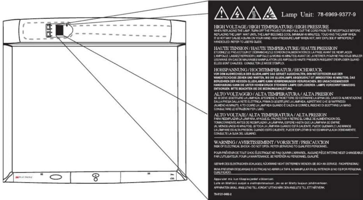
The following safety label is used on or within the 3M Digital WallDisplay to alert you to this area requiring your attention.
Save These Instructions
The information contained in this manual will help you operate and maintain your 3M Digital WallDisplay.
Trademarks
The 3M logo and 3M are registered trademarks of 3M Company. Vikuiti is a trademark of 3M Company.
Microsoft, Windows, Windows NT, Word, Excel, PowerPoint, Internet Explorer, and NetMeeting are either registered trademarks or trademarks of the Microsoft Corporation in the United States and/or other countries.
IBM is a registered trademark of International Business Machines Corporation.
Apple Macintosh and Apple PowerBook are registered trademarks of Apple Computer, Inc., registered in the U.S. and other countries.
Intel and Pentium are registered trademarks of Intel Corporation or its subsidiaries in the U.S. and other countries.
Digital Light Processing is a trademark or registered trademark of Texas Instruments.
eBeam, e-Beam, eBeam Mouse, eBeam Moderator, eBeam Software, ImagePort and eBeam Presenter are registered trademarks of Electronics for Imaging, Inc.
Sun and Java are trademarks or registered trademarks of Sun Microsystems, Inc. in the United States and other countries.
UNIX is a registered trademark in the United States and other countries, licensed exclusively through X/Open Company Limited.
Palm is a trademark of Palm Computing, Inc. or its subsidiaries.
Netscape and the Netscape N and Ship's Wheel logos are registered trademarks of Netscape Communications Corporation in the U.S. and other countries. Navigator and Communicator are also trademarks of Netscape Communications Corporation and may be registered outside the U.S.
All other products are trademarks or registered trademarks of their respective companies.
Patents
3M Digital WallDisplay is protected by Utility Patent 6,179,426 and Design Patent D442,205.
Other patents pending.
3M Digital WallDisplay Technical Support
• In U.S. or Canada: 1-800-328-1371
• Web Site: http://www.3M.com/walldisplay
FCC Statement—Class A
This device complies with Part 15 of the FCC Rules. Operation is subject to the following two conditions: (1) this device may not cause harmful interference, and (2) this device must accept any interference received, including interference that may cause undesired operation.
Instructions to Users
This equipment has been tested and found to comply with the limits for a Class A digital device, pursuant to Part 15 of the FCC Rules. These limits are designed to provide a reasonable protection against harmful interference when the equipment is operated in a commercial environment. This equipment generates, uses, and can radiate radio frequency energy and, if not installed and used in accordance with the instruction manual, may cause harmful interference to radio communications. Operation of this equipment in a residential area is likely to cause harmful interference in which case the user will be required to correct the interference at his own expense.
Notice
This Class A digital apparatus meets all requirements of the Canadian Interference-Causing Equipment Regulations.
This machine was tested against the 89/336/EEC (European Economic Community) for EMC (Electro Magnetic Compatibility) and fulfills these requirements.
Video Signal Cables
Double shielded coaxial cables (FCC shield cable) must be used, and the outer shield must be connected to the ground. If normal coaxial cables are used, the cable must be enclosed in metal pipes or in a similar way to reduce the interference noise radiation.
Video Inputs
The input signal amplitude must not exceed the specified level.
(See Appendix for these levels.)
Model Identification and Differences
Identify Model
The nameplate, located behind the storage door, identifies the 3M Digital WallDisplay (DWD). Push the storage door to open it. The figure below shows the nameplate, and the table shows the model numbers and corresponding model names.

| Model Number Model | Name |
| 9000PD 3M Digital Wa | IDisplay 9000PD for Projection Display |
| 9200IC 3M Digital Wa | Display 9200IC with Interactive Collaboration |
| 9200IW 3M Digital Wa | IDisplay 9200IW with Interactive Whiteboard |
Model Differences
Below is a table that identifies the differences between the 3M Digital WallDisplay models.
| Model Number Projection Screen Copyboard* | Interactive Whiteboard** | ||
| 9000PD | Easy Dry-Erase and Projection YES | NO NO | |
| 9200IW NO YES | |||
| 9200IC YES | |||
*The Copyboard feature allows you to print notes written on the 3M Digital WallDisplay to an attached printer. (PCL3 compatible printer required. See list in Appendix.)
**The Digital Whiteboard feature allows you to capture notes written on the 3M Digital WallDisplay with an attached computer or use the 3M Digital WallDisplay as an interactive display for a computer.
Contents
The 3M Digital WallDisplay is shipped with the necessary cables required for standard VCR, PC, Macintosh or laptop computer connections. Carefully unpack and verify that you have all of the items shown below. If any are missing, please contact your place of purchase.
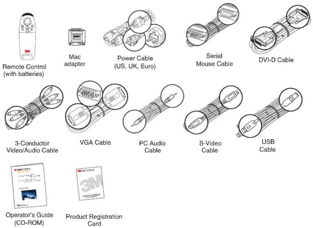
Optional Accessories
- Accessory Tray/Laptop Shelf
- Easy-Erase Screen
- Replacement Lamp Kit
- Extended Warranty
Note: Save the shipping box and packing materials in the event the 3M Digital WallDisplay should ever need to be moved.
What's Next?
After the 3M Digital WallDisplay has been installed in your meeting room, you are ready to set it up.
Please read this guide thoroughly before operating your new 3M Digital WallDisplay.
Be sure to check our web site (www.3M.com/walldisplay) regularly for updates and supplemental information.
Part Identification
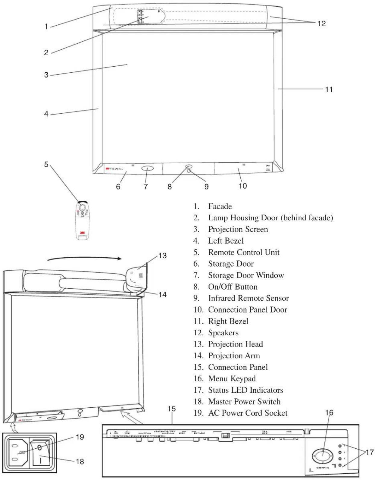
3M Digital WallDisplay Features
The 3M Digital WallDisplay combines the following features into one sleek, sophisticated package.
• Full connectivity for computer or video presentations
• Large 60" diagonal screen
- 4:3 screen aspect ratio matches business applications and viewing data
- Flat screen allows extra wide (up to 170^ ) viewing angles
- Projection arm position guarantees image is in focus every time
- Allows presenter to move without blocking image
• Built-in, powerful stereo speaker system
- Single button operation
- Hand-held remote control for most functions
Installation and System Setup
Recommendation and Things to Consider Before Installing
Location of Unit
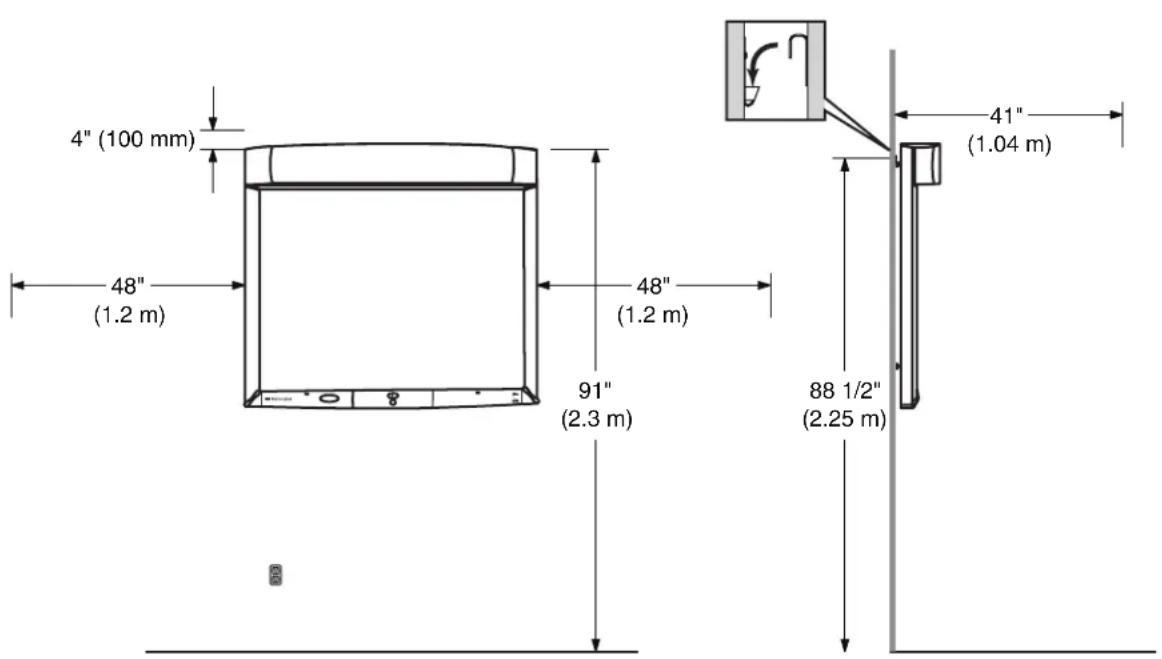
- Place near AC outlet. The AC power connection is located on the lower-left corner of the 3M Digital WallDisplay (the unit). The AC power cord supplied with the unit is 6 feet (2 m) long.
- Service and screen replacement – The projection screen is removed from the side of the unit during replacement or service. For ease of replacement and access, position the unit 48 inches from the nearest obstruction or adjacent wall.
- Low-hanging lights – The projection arm extends 3 1/3 feet from the unit while in operation. Ensure that the projection arm will not come in contact with low-hanging light fixtures.
Air Ventilation
- Minimum clearance around the unit should be 4 inches.
- Air Vents – keep the air vents clear of objects and dust.
Installing the Wall Bracket Unpacking Wall Bracket and Hardware
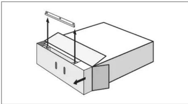
- Place the shipping container face up on the floor.
- Open the end of the shipping container.
- Slide the shipping tray partially out the container.
- Locate and Remove the wall bracket and hardware. The hardware is taped to the wall bracket.
natural_image
3D diagram of a mechanical assembly with arrows indicating direction (no text or symbols)Installation for a Hollow Wall-Drywall
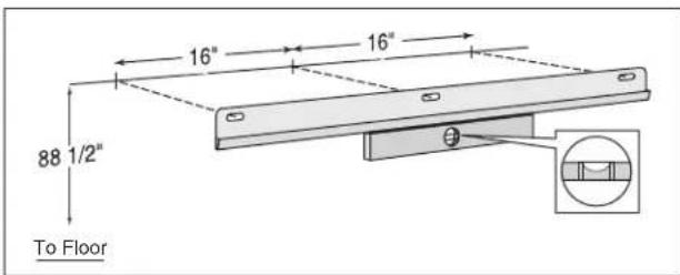
- Determine the desired location of the unit. Locate all wall studs in area.
- While holding the bracket in place, use a carpenter's level to ensure the proper level and then mark the three hole locations on the wall. Ensure that no studs are behind the hole locations.
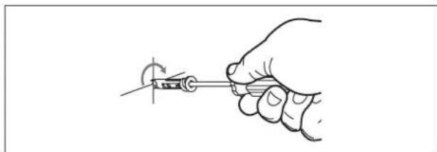
- Using a Phillips screw driver, screw the supplied anchors into the wall until they are flush with the wall surface.
natural_image
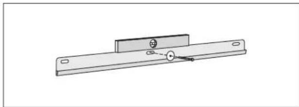
Hand holding a screwdriver with a rotating knob (no text or symbols visible)- Align the wall bracket holes over the wall anchors and secure with the washer and anchor screws. Confirm that the wall bracket is level before tightening the screws.
Note: For other types of wall material (e.g. wood, concrete, concrete block) use mounting hardware that is properly rated for the weight of the unit and is intended for specific wall material.
natural_image
Technical line drawing of a mechanical bracket with mounting holes and a central pin (no text or symbols)Hanging the 3M Digital WallDisplay
Unpacking the 3M Digital WallDisplay
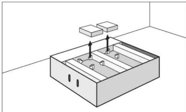
- Place the shipping container face up on the floor and open the end previous opened.
- Slide the shipping tray out of the shipping container.
- Remove the accessory box(es) from the top support.
-
Remove the top support.
-
Remove the plastic bag from the 3M Digital WallDisplay by lifting the top of the unit and pushing the bag towards the bottom of the unit. Then set down the top.
-
Lift up the bottom and remove the bag completely.
natural_image
Isometric diagram of a rectangular storage unit with internal compartments and two blocks above it (no text or symbols)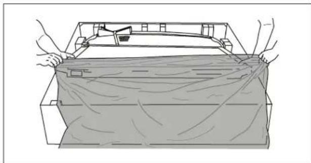
natural_image
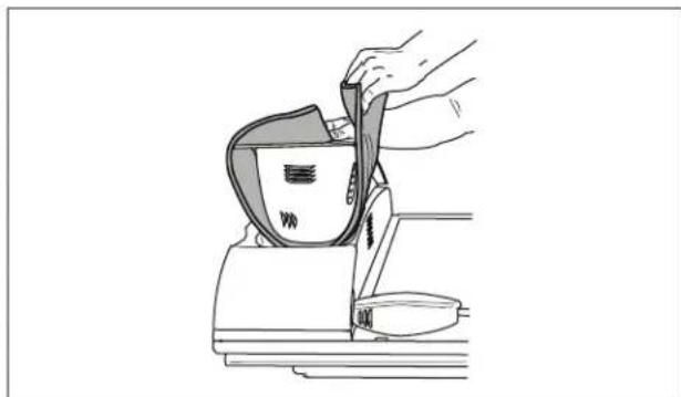
Line drawing of hands installing or adjusting a rectangular object with a cloth (no text or symbols)- Remove and set aside the tape holding the projection arm in place.
- Remove the projection arm shipping foam, by opening the projection arm from the left.
- Replace the tape to hold the projection arm in place while hanging on the wall.
natural_image
Line drawing of a hand using a tool to press or install a device, no text or symbols presentHanging on the Wall
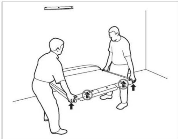
- If possible, position the 3M Digital WallDisplay and shipping tray in front of the wall where the bracket is located. Position the unit so that the projection arm is closest to the wall.
- Clear the path from the unit to the wall where it will be hanging.
Note: Most of the weight is at the projection head/speakers end of the 3M Digital WallDisplay.
natural_image
Line drawing of two people pushing a bed with directional arrows indicating movement (no text or symbols)-
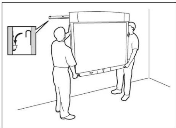
With one person holding each side of the unit, carefully lift it into position so that the bracket slot is above the wall bracket. Ensure that the unit is securely in place before releasing.
-
Remove the tape from the projection arm.
natural_image
Line drawing of two people installing or adjusting a large whiteboard in a room with a wall-mounted fixture (no text or symbols)System Setup
It only takes a few minutes to connect the 3M Digital WallDisplay to your computer, VCR, DVD player, video conference unit, or other devices.
The connection panel is located underneath the bottom right corner of the 3M Digital WallDisplay, under the Connection Panel Door. Press and release door to access connection panel.
Note: Use the enclosed cables to ensure image and audio quality. Substituting cables of lesser quality may result in poor image quality or audio noise.
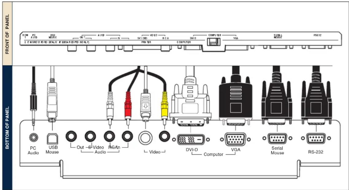
PC Audio Connects to the computer's audio output and provides audio for VGA and DVI-D (Digital Visual Interface - Digital only) inputs.
USB Mouse Connects to the computer's USB port and provides wireless mouse control using the 3M Digital WallDisplay remote control Disk Pad button.
Audio Out Connects to an external audio amplifier and provides audio from the active audio source.
Audio In Connects to the audio output of a video device (e.g. VCR or DVD), and provides audio for both S-Video and RCA video inputs.
S-Video Connects to an S-Video output signal.
RCA Video Connects to a composite video device.
DVI-D Connects to a computer that supports the DVI-D interface.
VGA Connects to the VGA or monitor Out port of a computer.
Serial Mouse Connects to a computer's 9-pin serial port and provides wireless mouse control using the 3M Digital WallDisplay remote control Disk Pad button.
RS-232 Connects to a control device's serial port and provides control of the 3M Digital WallDisplay using RS-232C protocol and the specified serial commands.
Operation
Startup
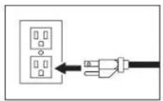
- Plug power cord into wall socket.
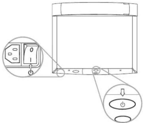
- Flip on the Master Power Switch beneath the lower left corner of the 3M Digital WallDisplay, near the 3M label. This should stay on at all times. Now the 3M Digital WallDisplay is in standby mode. The large oval On/Off Button will be backlit amber after several seconds.
-
Press the On/Off Button in the center of the lower front panel. The projection arm will extend outward from its housing at the top of the 3M Digital WallDisplay unit. Do not block its movement.
-
When the projection arm is fully extended, the lamp will turn on automatically. It will reach full illumination in approximately 60 seconds. The On/Off Button should then be backlit green.
Shutdown
-
Press the On/Off Button on the bottom center panel of the 3M Digital WallDisplay unit.
-
The lamp will turn off and the projector arm will return to its housing. The On/Off Button will flash red as the arm closes.
Note: There is a 30-second reset period before the On/Off Button will function again. During this period, the On/Off Button will flash red.
The fan will continue to run for approximately five minutes to cool the unit.
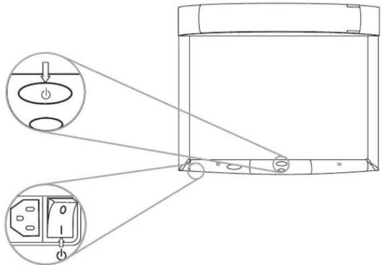
Note: If the 3M Digital WallDisplay will not be moved or disconnected, leave the Master Power Switch on for your convenience.
Do not turn off the Master Power Switch or unplug the power cord before pressing the On/Off Button. After the On/Off Button is pressed, the fan continues for approximately five minutes to cool the 3M Digital WallDisplay.
Remote Control Unit
Features
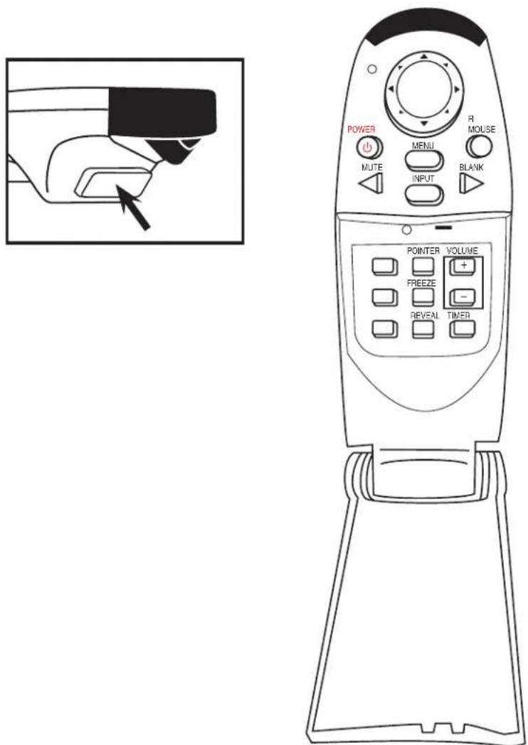
The remote control sensor is on the front lower panel of the 3M Digital WallDisplay unit. The distance between the sensor and remote control must be shorter than 4 meters (13 feet).
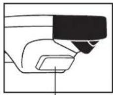
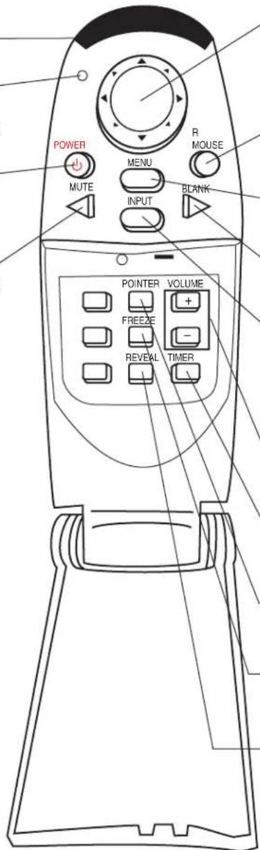
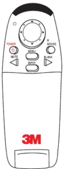
The remote control unit has two keypads. The Forward keypad is above the flip-top cover. The Rear keypad is beneath the cover. The Trigger Button is underneath the front IR Sensor of the remote control unit and can be pressed easily with the index finger.
FORWARD KEYPAD
IR SENSOR
Transmits infrared signals to 3M Digital WallDisplay unit.
LED
Indicates that remote control unit is transmitting signal.
POWER
Press to turn 3M Digital WallDisplay on/off.
MUTE
Press to turn the audio (speaker) function on/off.
natural_image
Line drawing of a mechanical component or device with no visible text or symbolsTRIGGER BUTTON
Press for left-mouse button functions.
DISK PAD
Press to control the computer's mouse, navigate the menu system, or control the Pointer or Reveal functions.
R MOUSE
Press for right-mouse-button function in mouse mode.
MENU
Press to display onscreen menu system.
BLANK
Press to turn the screen-blanking function on/off.
INPUT
Press to change source of input.
REAR KEYPAD
VOLUME
Press to adjust the speaker and Audio Out sound level.
TIMER
Press to turn on/off display of countdown timer.
POINTER
Press to turn the pointing function on/off.
FREEZE
Press to turn the still-mode function on/off.
REVEAL
Press to uncover part of the screen from top to bottom or from left to right.
Forward Keypad
Power
Press to turn the 3M Digital WallDisplay on/off. When power is turned on, the 3M Digital WallDisplay will automatically extend the projection arm and ignite the lamp.
Mute
Press to temporarily turn off the sound. Press again or press the Volume + or - buttons to restore sound.
Disk Pad
Press to:
- control the computer's mouse when using the Mouse function.
- select menu items and adjust values in the onscreen menu system.
• control the Pointer position while using the Pointer function.
• control the path of the Reveal function.
While using the onscreen menu system or Pointer function, the computer Mouse function is temporarily disabled. To regain computer mouse control, turn off the current function or the onscreen menu system.
Note: The USB or serial mouse cable must be connected between the 3M Digital WallDisplay and the computer when using Mouse mode.
R Mouse
Acts as the right-mouse button when the mouse function is active.
Menu
Press to display the onscreen menu system. Press again to conceal the onscreen menu system.
Blank
Press to make the screen go blank. Press again to return to normal display function.
Input
Press to change the source of input for 3M Digital WallDisplay. The Input button cycles between Computer, DVI, Composite Video (RCA jacks), and S-Video.
Rear Keypad
Pointer
Press to turn the pointing function on/off. A green dot will appear on the screen. The dot can be controlled by pressing the arrows on the Disk Pad.
Volume
Press the + button to increase or the - button to decrease the speaker loudness level. When the audio is muted, the Volume + or - buttons will also cancel the Mute function.
Timer
Press to turn the timing function on/off. The timer will display on the screen and begin to count down. To change the Timer value, refer to the On Scrn Timer sub-menu in the Tools menu.
Freeze
A moving image can be stilled or 'frozen' when the Freeze button is pressed. To release the Freeze function, press the Freeze button again.
Reveal
Press to turn the screen-reveal function on/off. Press the Disk Pad in the desired reveal direction (e.g. press down to reveal from the top down, etc.).
Trigger Button
On the underside of the remote control unit, beneath the IR sensor, press button for left-mouse-button functions.
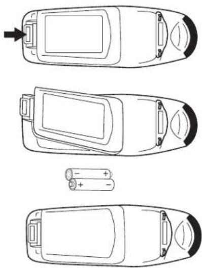
Installing or Replacing Batteries
- Push and slide the battery compartment tab in the direction shown, then lift it off.
- Install two AAA batteries as indicated by the diagram inside the compartment.
- Snap the battery compartment cover back on.
natural_image
Top-down line drawings of four car body parts with battery and charging elements (no text or symbols)Note: Avoid excessive heat and humidity. Do not mix old and new batteries or different types of batteries.
Menu System
Menu Navigation
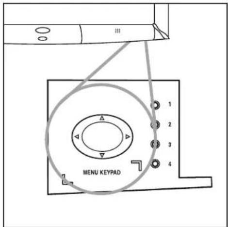
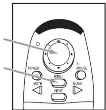
Most adjustments and settings are available in the main menu and sub-menus. To navigate and make adjustments, use the 3M Digital WallDisplay's Menu Keypad button or the remote control's Menu and Disk Pad buttons.
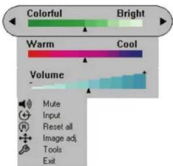
Colorful—Bright Slider
The Colorful—Bright slider adjusts the brightness, contrast, and color saturation levels simultaneously. Move the slider toward Colorful to achieve maximum color saturation and contrast. Move the slider toward Bright to achieve maximum brightness.
To adjust the Colorful—Bright slider:
-
Open the menu system by pressing the remote control Menu button or any arrow on the Menu Keypad.
-
Select the Colorful—Bright slider by pressing the up or down arrows on the remote control Disk Pad or Menu Keypad.
-
Move the slider by pressing the left or right arrow of the Disk Pad or Menu Keypad.
-
Close the menu system by pressing the Menu button or scrolling to Exit and selecting it with the right arrow of the Menu Keypad.
Warm—Cool Slider
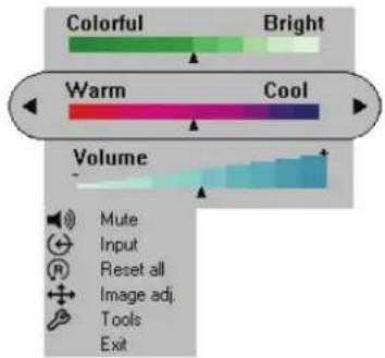
The Warm—Cool slider adjusts the color temperature. Move the slider toward Warm to achieve warmer, more reddish images. Move the slider toward Cool to achieve cooler, more bluish images.
To adjust the Warm—Cool slider:
-
Open the menu system by pressing the remote control Menu button or any arrow on the Menu Keypad.
-
Select the Warm—Cool slider by pressing the up or down arrows on the remote control Disk Pad or Menu Keypad.
-
Move the slider by pressing the left or right arrow of the Disk Pad or Menu Keypad.
-
Close the menu system by pressing the Menu button or scrolling to Exit and selecting it with the right arrow of the Menu Keypad.
Volume Slider
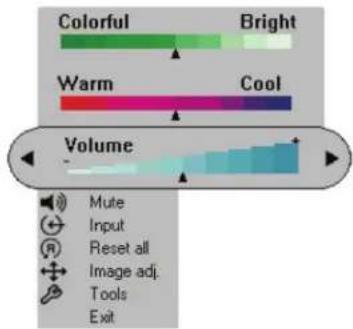
The Volume slider adjusts the speaker and audio output sound level. Move the slider toward the right to increase the sound. Move the slider toward the left to decrease the sound.
To adjust the Volume slider:
-
Open the menu system by pressing the remote control Menu button or any arrow on the Menu Keypad.
-
Select the Volume slider by pressing the up or down arrows on the remote control Disk Pad or Menu Keypad.
-
Move the slider by pressing the left or right arrow of the Disk Pad or Menu Keypad.
-
Close the menu system by pressing the Menu button or scrolling to Exit and selecting it with the right arrow of the Menu Keypad.
Mute Menu Function
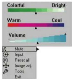
The Mute menu function turns the sound on and off.
To turn the Mute menu function on:
-
Open the menu system by pressing the remote control Menu button or any arrow on the Menu Keypad.
-
Select the Mute menu function by pressing the up or down arrows on the remote control Disk Pad or Menu Keypad.
-
Turn the Mute function on by pressing the left or right arrow of the Disk Pad or Menu Keypad. The sound will turn off.
-
Close the menu system by pressing the Menu button or scrolling to Exit and selecting it with the right arrow of the Menu Keypad.
Mute function ON
To turn the Mute menu function off:
-
Open the menu system by pressing the remote control Menu button or any arrow on the Menu Keypad.
-
Select the Mute menu function by pressing the up or down arrows on the remote control Disk Pad or Menu Keypad.
-
Turn the Mute function off by pressing the left or right arrow of the Disk Pad or Menu Keypad. The sound will turn on.
-
Close the menu system by pressing the Menu button or scrolling to Exit and selecting it with the right arrow of the Menu Keypad.
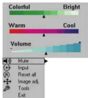
Mute function OFF
Input Select Menu
The Input Select menu defines the displayed video source. When Input Select menu is selected, the current video source is shown. The Input options are: Computer (VGA Input), DVI-D, S-Video, Comp. Video (RCA Video Input), and No Signal. An Input option is available to select when an active video source is connected to the 3M Digital WallDisplay input connection.
To set the Input Select menu:
- Open the menu system by pressing the remote control Menu button or any arrow on the Menu Keypad.
- Select the Input Select menu function by pressing the up or down arrows on the remote control Disk Pad or Menu Keypad.
- Press the right arrow of the Disk Pad or Menu Keypad repeatedly until the desired input option is shown.
- Activate the input option by pressing the left arrow of the Disk Pad or Menu Keypad.
- Close the menu system by pressing the Menu button or scrolling to Exit and selecting it with the right arrow of the Menu Keypad.
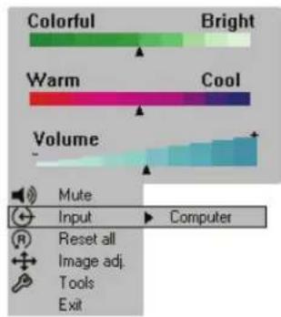
Reset All Menu
The Reset All menu function sets all menu settings to their default settings.
To turn the Reset All menu function on:
-
Open the menu system by pressing the remote control Menu button or any arrow on the Menu Keypad.
-
Select the Reset All menu function by pressing the up or down arrows on the remote control Disk Pad or Menu Keypad.
-
To activate the Reset All function, press the right arrow of the Disk Pad or Menu Keypad.
-
Close the menu system by pressing the Menu button or scrolling to Exit and selecting it with the right arrow of the Menu Keypad.
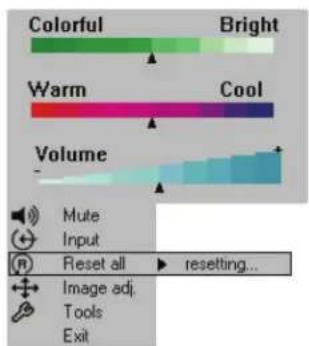
Image Adj Sub-Menu
The Image Adjustment sub-menu adjusts the projected image settings for the VGA and DVI-D inputs. Use the Vertical Position and Horizontal Position sliders to reposition an image if portions are not visible. Use the Phase and Sync sliders to eliminate vertical banding and noise.
Vertical Position Adjusts the vertical position of the projected image.
Horizontal Position Adjusts the horizontal position of the projected image.
Phase Adjusts the pixel sampling. Use this to reduce image noise and flicker.
Sync Adjusts the expected pixel number in a single video line. Use this to eliminate banding.
Main Returns to main menu.
Exit Leaves the menu system.
To open the Image Adj submenu:
-
Open the menu system by pressing the remote control Menu button or any arrow on the Menu Keypad.
-
Select the Image Adj sub-menu by pressing the up or down arrows on the remote control Disk Pad or Menu Keypad.
-
To open the Image Adj sub-menu, press the right arrow of the Disk Pad or Menu Keypad.
-
Scroll to the desired slider and move it to the right or left as needed.
-
Close the menu system by pressing the Menu button or scrolling to Exit and selecting it with the left or right arrow of the Menu Keypad.
To return to the main menu, select Main and press the left or right arrow of the Disk Pad or Menu Keypad.
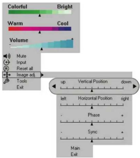
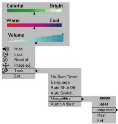
Tools Sub-Menu
The Tools sub-menu provides access to the following settings and tools:
Onscreen Timer Allows you to set a timer and display it onscreen.
Language Selects which language to use for onscreen commands. (Default language is
English.) It cycles between English, German, Spanish, Italian, and French.
Auto Shutoff
Will automatically turn off the 3M Digital WallDisplay within the time desired. (Default time is 0 minutes.)
Auto Switch
When an input source is lost or disconnected, Auto Switch automatically detects and switches to the next available input source. When Auto Switch is disabled, press the Input button on the remote control to select the next available input source.
Usage/Hrs Displays and/or resets 3M Digital WallDisplay's and lamp's operating time, in number of hours.
Audio Adjust Allows you to adjust the bass and treble.
To open the Tools sub-menu:
- Open the menu system by pressing the remote control Menu button or any arrow on the Menu Keypad.
- Select the Tools sub-menu by pressing the up or down arrows on the remote control Disk Pad or Menu Keypad.
- To open the Tools sub-menu, press the right arrow of the Disk Pad or Menu Keypad.
- Scroll to the desired item and adjust as needed.
- Close the menu system by pressing the Menu button or scrolling to Exit and selecting it with the right arrow of the Menu Keypad.
To return to the main menu, select Main and press the left or right arrow of the Disk Pad or Menu Keypad.
Maintenance
General Maintenance
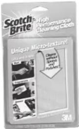
For general cleaning of the screen and exterior of the 3M Digital WallDisplay, use a damp cloth or dry cleaning cloth such as the 3M High Performance Cleaning Cloth.
Standard dry-erase cleaners may be used on the dry-eraseable screens, such as Sanford ^ Expo ^ Whiteboard Cleaner. Do not use other spray cleaners or solvents on any part of the 3M Digital WallDisplay.
Lamp Usage
Use and Replacement of Lamp
The 3M Digital WallDisplay lamp has a normal operating time of approximately 1600 hours, called the lamp life. After the lamp has been operating for 1400 hours or longer, the following messages will appear on the screen for the first three minutes of operation. When this happens, turn off the 3M Digital WallDisplay and replace the lamp with a new one. Using an old lamp in the 3M Digital WallDisplay could cause a malfunction.
Onscreen Lamp Messages
PLEASE CHANGE THE LAMP
The lamp has been in use for 1400–1499 hours and needs to be changed. After replacing the lamp, reset the lamp timer.
THERE ARE (x) HOURS OF LAMP LIFE REMAINING THE WALLDISPLAY WILL SHUT OFF IN 40 MINUTES
The lamp has been in use for 1500–1579 hours, and the power will turn off after 40 more minutes. After replacing the lamp, reset the lamp timer.
THERE ARE (x) HOURS OF LAMP LIFE REMAINING THE WALLDISPLAY WILL SHUT OFF IN 5 MINUTES
The lamp has been in use for more than 1580 hours, and the power will automatically turn off after 5 minutes. After replacing the lamp, reset the lamp timer.
All of these messages will display for no longer than three minutes, but each will display whenever you turn the lamp on again, until the lamp is replaced.
For lamp-changing instructions, please refer to the next page.
Lamp Replacement
- Turn the power off and disconnect the power cord from the outlet.
- Allow approximately 45 minutes for the lamp to cool, if necessary.
-
There are two indentations behind the top of the facade, near each end. Grasp facade plate at each indentation and pull out and down to remove plate.
-
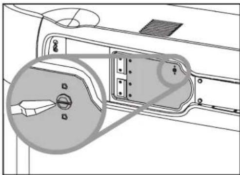
Loosen the self-contained screw at the upper righthand corner of the lamp housing door with a standard screwdriver.
-
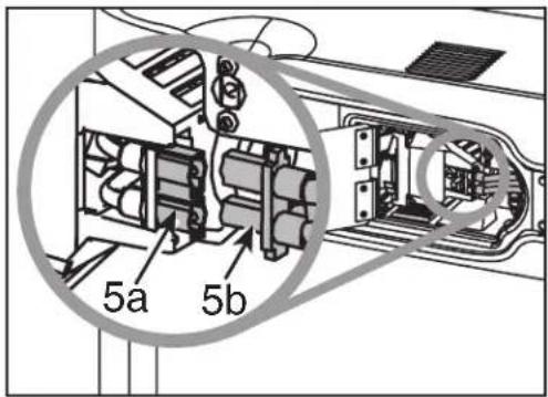
Two black wires connect to the lamp cartridge by a black plastic receptacle on the right side of the lamp cartridge.

natural_image
Technical diagram of a vehicle door panel with a magnified inset showing internal components (no text or symbols)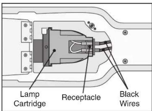
5a. Hold down this receptacle with your left thumb and (5b) pull connectors out of the receptacle with other hand.
-
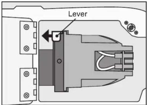
Open the latch by moving the metal lever to the left.
-
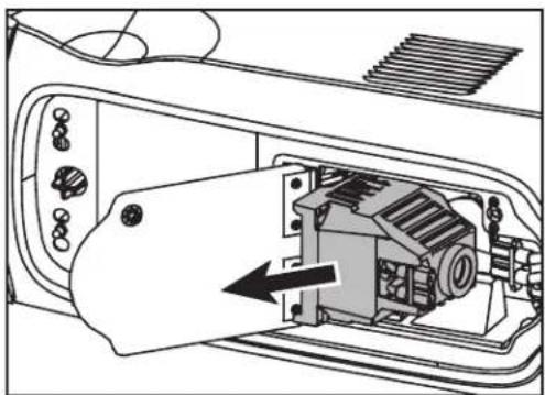
While holding the latch open, grasp the lamp cartridge and pull it straight out of the lamp compartment.
-
Holding the latch open, slide the new lamp cartridge into place.
-
Reconnect black wires to the receptacle.
-
Close the lamp housing door and tighten the screw.
natural_image
Technical line drawing of an internal combustion engine component (no text or symbols)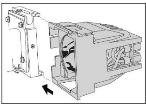
natural_image
Technical illustration of a mechanical device showing internal components and airflow direction (no text or symbols)-
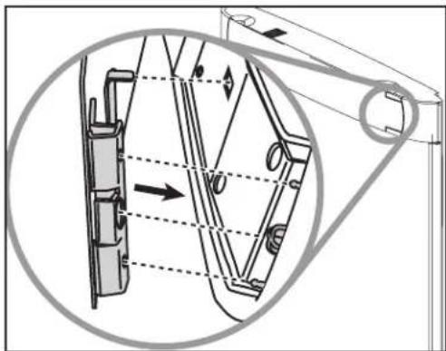
Align the slots and tabs of the right side of the facade and projection arm as shown, then snap firmly into place.
-
Align the slots and tabs of the left side of the facade and projection head as shown, then snap firmly into place.
Note: You must hear or feel a distinctive snap to ensure facade is securely attached.
natural_image
Technical diagram of a mechanical assembly with directional arrows indicating motion or force (no text or symbols present)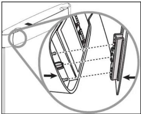
natural_image
Technical diagram of a mechanical assembly with an inset showing internal components (no text or labels)Whenever the lamp is replaced, please reset the total lamp operating time. (Refer to next page.)
Resetting Lamp Hours
Please do the following within 10 minutes of turning power on after you replace the lamp.
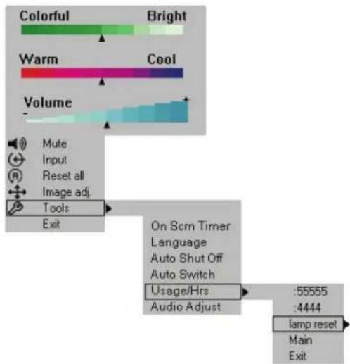
- Press the Menu Keypad or the Menu button on the remote control and use the Disk Pad to scroll down to the Tools menu.
- In the Tools menu, scroll down the pop-up list to Usage/Hrs to display the total operating time of the lamp.
- Select Lamp Reset from the next pop-up list.
- Select Exit.
Note: Do not reset the lamp hours if the lamp cartridge was not changed. This can damage internal components.
Important Note: This lamp contains mercury. Don't throw lamp cartridge in the trash. Dispose of the lamp cartridge in accordance with your respective governmental agencies for hazardous waste. For disposal information in the US, contact the Electronic Industries Alliance at www.lamprecycle.org. In Canada contact the Electronic Product Stewardship Canada at www.wpsc.ca.
Replacing ProjectionScreen
Replacing the 3M Digital WallDisplay screen is very simple.
- Turn off the 3M Digital WallDisplay and disconnect the power cord from the wall outlet.
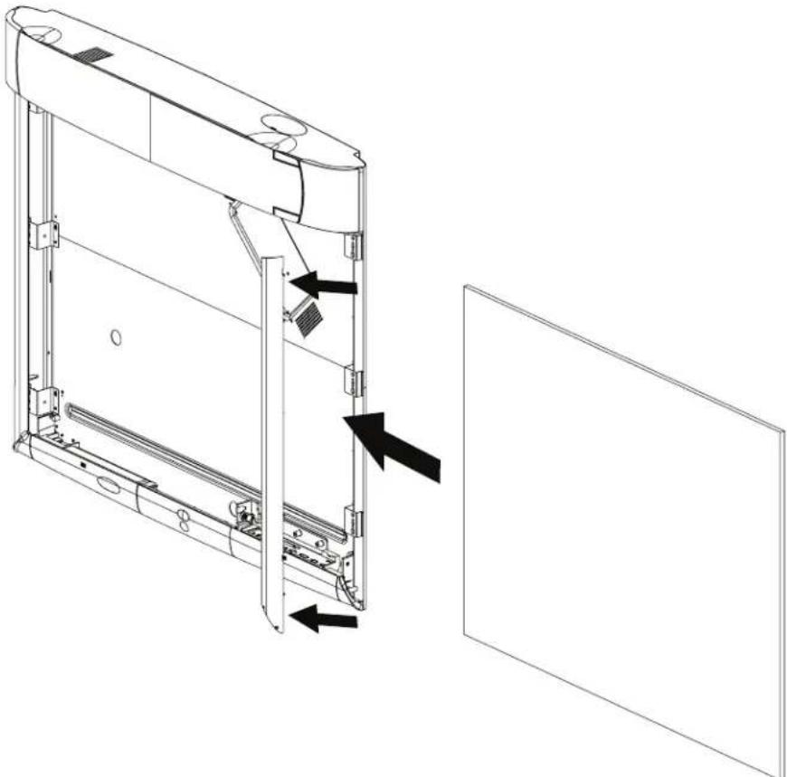
- Remove the right and left side bezels. There are two ways to remove it. Either snap it off or insert a screwdriver into the notch located on the sides of each bezel, near the top. The bezel will easily snap on and off for screen replacement.
- Slide the screen straight out of the open side. Be sure to allow approximately 4 feet of clear space on either side of the 3M Digital WallDisplay to do this.
- Insert new screen into the open side and slide into place. Ensure that the screen is centered before replacing the side bezels. The bezels have ribs on the inside that could damage the screen if it is not centered.
- Insert the bottom of the bezel first, then snap bezel back into place.
natural_image
Technical line drawing of a mechanical assembly with arrows indicating components, no text or symbols presentOptical Engine Adjustment
The optical engine needs to be aligned when the vertical or horizontal images do not cover the screen or are tilted.
Note: Before continuing with this adjustment, move the arm assembly up and down to relieve any stress and see if the arm will realign itself and project an aligned image.
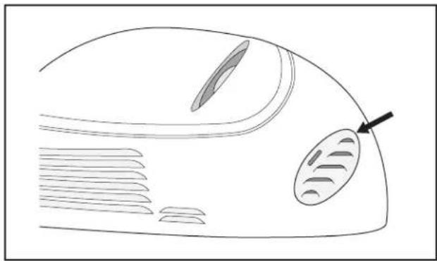
- Locate the access door on the under side of the projection arm.
natural_image
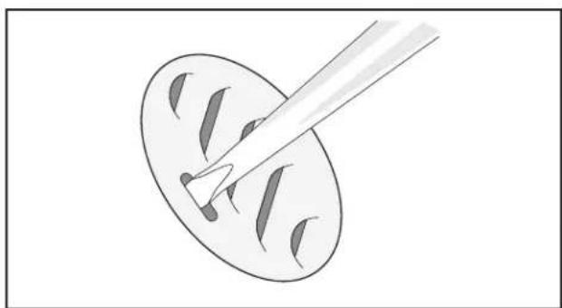
Diagram of a biological structure with labeled parts and an arrow pointing to a feature (no text or symbols present)- Slide the door release catch to the open position using the blade of a small screwdriver. Carefully lift outward to remove the optical engine door.
natural_image
Simple line drawing of a paintbrush touching a circular surface with visible paint spots (no text or symbols)- Locate adjustment screw for side to side screen adjustment. Locate locking screw for side to side adjustment.
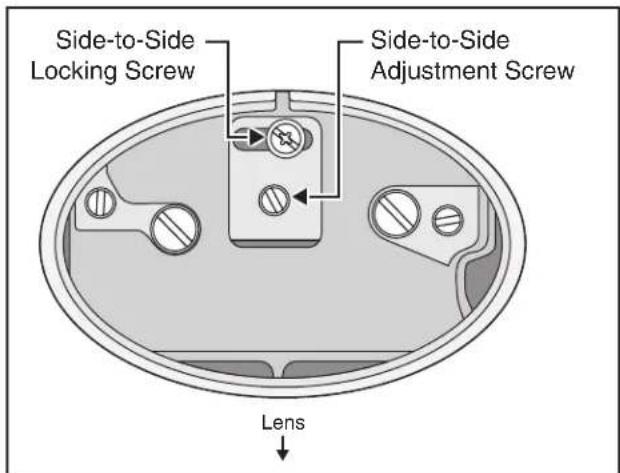
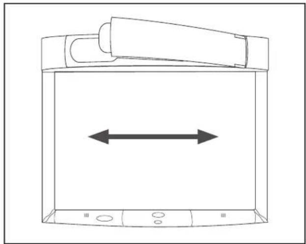
- Loosen locking screw. Then use blade screwdriver on adjustment screw to move screen image from side to side if required. Tighten locking screw.
natural_image
Line drawing of a device with a double-headed arrow indicating horizontal displacement (no text or symbols)- Locate adjustment screw for right side screen adjustment. Locate locking screw for right side adjustment.
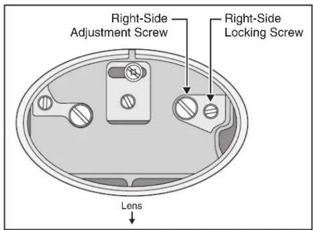
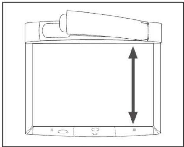
- Loosen locking screw. Then use blade screwdriver on adjustment screw to move right side screen image up and down if required. Tighten locking screw.
natural_image
Line drawing of a device with a vertical double-headed arrow indicating horizontal displacement (no text or symbols)- Locate adjustment screw for left side screen adjustment. Locate locking screw for left side adjustment.
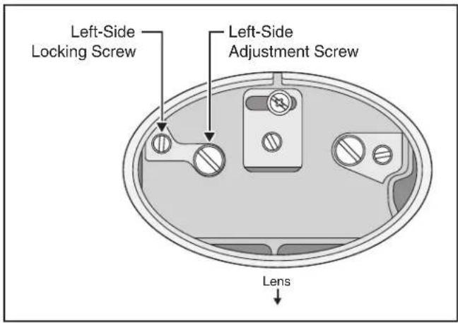
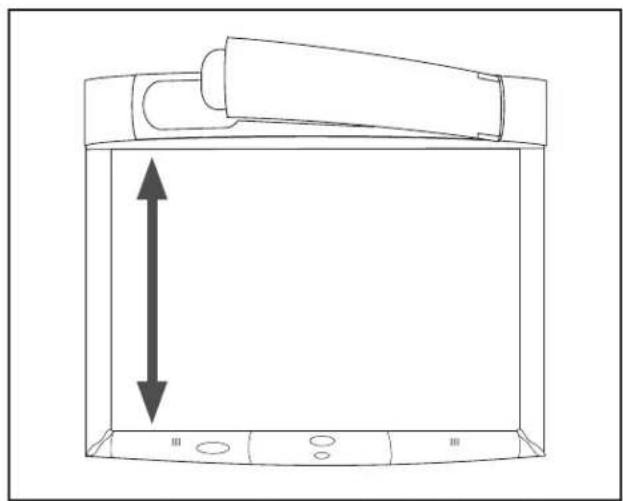
- Loosen locking screw. Then use blade screwdriver on adjustment screw to move left side screen image up and down if required. Tighten locking screw.
Note: After making adjustments it may be necessary to perform the side to side adjustment to center the image properly.
natural_image
Line drawing of a device with a vertical double-headed arrow indicating leftward movement (no text or symbols)- Replace the optical adjustment door.
Troubleshooting
Common Problems and Solutions
| Symptom Cause Solution | ||
| Power cannot be turned on. The power cord is disconnected. Insert the power cord into an AC socket.The Master Power Switch is not turned on.The arm facade is not in place. Make sure the arm facade is in place. | ||
| No picture or sound The desired input source is not selected.The cables from the input source are not connected.The input source is not turned on or not displaying an image. (e.g. If a notebook computer, the external monitor port is not turned on.) | Press the remote control Input button to select a desired input source.Connect the cable to correct input source.Turn on input source | |
| The lamp will not ignite or has turned off. | The internal temperature is too high.The lamp has reached maximum life or has prematurely failed. | Clear blocked ventilation holes.Replace lamp. |
| The projection arm opens, then closes. | The lamp will not ignite. Replace lamp. | |
| Sound is heard with no picture. The VGA/Video cables are not connected.The VGA/Video/Audio cables are connected to the wrong input. | Connect the cables to the correct input source. | |
| Picture is displayed with no sound The VGA/Video cables are not connected.The audio cables are connected to the wrong input.The volume is set to Minimum. Turn up Volume. | Connect the cables to the correct input source. | |
| Turn off Mute. | ||
| Picture is dark. | The Colorful—Bright setting must be adjusted.The lamp needs to be replaced. | Adjust Colorful—Bright slider setting.Replace lamp. |
Common Problems and Solutions
| Symptom Cause Solution | ||
| Desired input source cannot be detected. | The input source is not active.A signal must be present for the input to be selected.The input device (e.g. computer, VHS player, etc.) is not turned on. | Connect an active input source to unit.Turn on input source |
| The remote control does not work The remote control is not facing the remote control sensor.The remote control is too far from the sensor.An obstruction is between the remote control and the sensor.The remote control's batteries are exhausted. | Face the remote control toward the remote control sensor.Operate the remote control within 5 meters.Remove obstacle.Replace batteries. | |
| The menu system will not display. The menu system will not display without an input source displayed. | Connect an active input source to unit. | |
Onscreen Messages
| Message Meaning | |
| No input is detected 3M Digital WallDisplay is not receiving a signal from an external source. Check the cable connections and verify power is on and external source is working. | |
| Please change the lamp The lamp has 1400–1499 hours on it and needs to be changed. | |
| There are (x) hours of lamp life remaining.The WallDisplay will shut off in 40 minutes | The lamp has 1500–1579 hours on it and needs to be changed. |
| There are (x) hours of lamp life remaining.The WallDisplay will shut off in 5 minutes | When the lamp has 1580 hours or more on it, the message will flash, and the power will turn off after 5 minutes. |
Service Information
Replacement Parts
| Description | Part Number |
| Power Cord (EU) | 78-8131-0004-3 |
| Power Cord (US) | 78-8131-0005-0 |
| Power Cord (UK) | 78-8131-0003-5 |
| Serial Mouse Cable | 26-1015-0423-6 |
| USB Cable | 26-1015-0424-4 |
| VGA Cable | 26-1015-0425-1 |
| DVI-D Cable | 26-1015-0418-6 |
| PC Audio Cable | 26-1015-0420-2 |
| S-Video Cable | 26-1015-0422-8 |
| Replacement Lamp | 78-6969-9736-6 |
| Remote Control Unit | 78-8121-0330-3 |
| Macintosh Adapter | 26-1015-0419-4 |
| 3-Conductor Video/Audio Cable | 26-1015-0421-0 |
| Easy Erase Screen | 78-6969-9469-4 |
| 3M Vikuiti High Brightness Screen | 78-6969-9471-0 |
Optional Accessories
| Accessory Tray (right side) | 78-6969-9753-1 |
| Accessory Tray (left side) | 78-6969-9754-9 |
Ordering Parts or Getting Information
For product information, product assistance, service information, or to order accessories, please contact 3M Customer Service at the following numbers:
• In U.S. or Canada: 1-800-328-1371
- In other locations, contact your 3M Sales office.
The contents of this manual are subject to change without prior notice.
3M assumes no responsibility for the infringement of special rights of a third party or other rights that may arise out of the information contained in this manual.
Reproduction of this manual in any form without prior permission is strictly prohibited.
Appendix
3M™ Digital WallDisplay Specifications
| Display Size 60" Diagonal viewing area | ||
| Display Aspect Ratio | 4:3 | |
| Display System Single Chip, DLPTM Texas Instruments | technology | |
| DLP Chip | Chip Diagonal Size 0.7 inch | |
| Number of Pixels 1024 x 768 pixels | ||
| Color 24-bit full color | ||
| Contrast Ratio | 150:1 | |
| Dimensions | 47.6" H x 53.2" W x 7.0" D(1208 mm x 1350 mm x 179 mm) | |
| Weight Approx. 85 lbs. | ||
| Video Compatibility NTSC, NTSC 4.43, PAL, PAL-N, PAL-M, SECAM | ||
| Computer Video Compatibility VGA to SXGA | ||
| Mouse Emulation PC serial mouse, ADB and USB | ||
| Input/Output Terminal | Computer Input Signals | Analog RGB: 15-pin mini D-Sub |
| Digital RGB: DVD-D (digital only) | ||
| Audio: 3.5 mm stereo mini-jack | ||
| Video Input Signals S-Video | Mini DIN 4-pin | |
| Audio Out RCA jacks | ||
| RS-232 Control Port | 9-pin D-Sub | |
| Mouse Emulation Port | 9-pin D-Sub | |
| Audio System | Amplifier (to speakers) | 20 Watts per channel |
| Speakers | 40 Watts Max., 8 ohms | |
| Power Requirements | 100~240 VAC, 50/60 Hz, 400 Watts Max. | |
Input/Output Signal Specifications
| Computer | Video Signal | Analog 0.7Vp-p, 75 Ohms termination (positive polarity) | |
| Horizontal Sync Signal | TTL Level (positive/negative polarity) | ||
| Vertical Sync Signal | TTL Level (positive/negative polarity) | ||
| Audio Input Signal | 200m Vrms, 20k Ohms (Max 3.0Vp-p) | ||
| Audio Output Signal 0~200m Vrms, 1k Ohms | |||
| Video | S-Video | Luminance Signal 1.0Vp-p, 75 Ohms | |
| Chrominance Signal 0.286Vp-p (color burst), 75 Ohms | |||
| Video Signal 1.0Vp-p, 75 Ohms | |||
| Audio Input Signal 200m Vrms, 20k Ohms | |||
Computer Compatibility
| Resolution Refresh Rate Horizontal Frequency | ||
| 640x400 | 85 Hz 37.9 kHz | |
| 60 Hz 31.5 kHz | ||
| 72 Hz 37.9 kHz | ||
| 75 Hz 37.5 kHz | ||
| 85 Hz 43.3 kHz | ||
| 800x600 | 56 Hz 35.1 kHz | |
| 60 Hz 37.9 kHz | ||
| 72 Hz 48.1 kHz | ||
| 75 Hz 46.9 kHz | ||
| 85 Hz 53.7 kHz | ||
| 1024x768 | 60 Hz 48.4 kHz | |
| 70 Hz 56.5 kHz | ||
| 75 Hz 60.0 kHz | ||
| 85 Hz 68.7 kHz | ||
| 1280x1024 60 Hz 64.0 kHz | ||
Important Notice
All statements, technical information, and recommendations related to 3M's products are based on information believed to be reliable, but the accuracy or completeness is not guaranteed. Before using this product, you must evaluate it and determine if it is suitable for your intended application. You assume all risks and liability associated with such use. Any statements related to the product which are not contained in 3M's current publications, or any contrary statements contained on your purchase order shall have no force or effect unless expressly set forth in a written agreement signed by an authorized officer of 3M.

http://www.3M.com/walldisplay e-mail: meetings@mmm.com
3M Austin Center
Building A145-5N-01
6801 River Place Blvd.
Austin, TX 78726-9000
3M Canada
P.O. Box 5757
London, Ontario
N6A 4T1
3M Mexico, S.A. de C.V.
78-6970-9380-1 Rev. B
- Contents
- Introduction
- Installation and System Setup
- Operation
- Remote Control Unit
- Menu System
- Maintenance
- Troubleshooting
- Service Information
- Appendix
- Thank You for Choosing 3M
- Safety Information
- Intended Use
- ⚠ WARNING
- To reduce the risk associated with hazardous voltage:
- To reduce the risk associated with hazardous voltage and fire:
- To reduce the risk associated with muscle strain and impact:
- To reduce the risks associated with glass dust falling from the projection arm into the eye:
- To reduce the risk associated with high temperature related to a hot lamp assembly:
- To reduce the risk associated with the release of high pressure related to a hot lamp:
- To reduce the risk associated with unexpected lamp rupture related hazards:
- To reduce the risk associated with choking:
- To reduce the risk of associated with environmental contamination, due to mercury in the projection lamp:
- WARNING
- To reduce the risk of environmental contamination due to lead based solder:
- To reduce the risk associated with radio interference:
- To reduce the risks associated with hazards related to the use of alcohol based cleaners;
- CAUTION
- To reduce the risk associated with tripping over cables:
- To reduce the risk associated with chemical leakage, hot battery surface, and battery rupture:
- To reduce the risks associated with impact from the projection arm and tripping over the legs of the portable cart:
- IMPORTANT NOTES
- Product Safety Label
- Save These Instructions
- Trademarks
- Patents
- 3M Digital WallDisplay Technical Support
- FCC Statement—Class A
- Instructions to Users
- Notice
- Video Signal Cables
- Video Inputs
- Model Identification and Differences
- Identify Model
- Model Differences
- Optional Accessories
- What's Next?
- Part Identification
- 3M Digital WallDisplay Features
- Recommendation and Things to Consider Before Installing
- Location of Unit
- Air Ventilation
- Installing the Wall Bracket Unpacking Wall Bracket and Hardware
- Installation for a Hollow Wall-Drywall
- Hanging the 3M Digital WallDisplay
- Unpacking the 3M Digital WallDisplay
- Hanging on the Wall
- System Setup
- Startup
- Shutdown
- Features
- FORWARD KEYPAD
- IR SENSOR
- LED
- POWER
- MUTE
- TRIGGER BUTTON
- DISK PAD
- R MOUSE
- MENU
- BLANK
- INPUT
- REAR KEYPAD
- VOLUME
- TIMER
- POINTER
- FREEZE
- REVEAL
- Installing or Replacing Batteries
- Menu Navigation
- Colorful—Bright Slider
- Warm—Cool Slider
- Volume Slider
- Mute Menu Function
- Input Select Menu
- Reset All Menu
- Image Adj Sub-Menu
- Tools Sub-Menu
- General Maintenance
- Lamp Usage
- Use and Replacement of Lamp
- Onscreen Lamp Messages
- PLEASE CHANGE THE LAMP
- THERE ARE (x) HOURS OF LAMP LIFE REMAINING THE WALLDISPLAY WILL SHUT OFF IN 40 MINUTES
- THERE ARE (x) HOURS OF LAMP LIFE REMAINING THE WALLDISPLAY WILL SHUT OFF IN 5 MINUTES
- Lamp Replacement
- Resetting Lamp Hours
- Replacing ProjectionScreen
- Optical Engine Adjustment
- Ordering Parts or Getting Information
Brand : 3M
Model : 9000PD
Category : Projector