
MP7650 - Projector 3M - Free user manual and instructions
Find the device manual for free MP7650 3M in PDF.


| Product Type | Portable LCD Video Projector |
| Brand | 3M |
| Model | MP7650 |
| Display Technology | 3LCD |
| Brightness | 3000 ANSI Lumens |
| Native Resolution | XGA (1024 x 768) |
| Contrast Ratio | 2000:1 |
| Lamp Life | Up to 5000 hours (Eco Mode) |
| Projection Distance | 1.2 m – 12 m |
| Image Size | 30 – 300 inches |
| Video Compatibility | NTSC, PAL, SECAM |
| Inputs | VGA, Composite Video, S-Video, USB Type B |
| Audio Output | 3.5 mm headphone jack |
| Internal Speaker | 1 x 3W mono |
| Power Consumption | 290W (Max), <1W (Standby) |
| Power Supply | AC 100-240V, 50/60 Hz |
| Dimensions (W x D x H) | 307 x 229 x 95 mm |
| Weight | 2.9 kg |
| Operating Temperature | 5°C – 35°C |
| Keystone Correction | Vertical ±30° |
| Remote Control | Included (IR) |
| Lamp Type | UHP 210W |
| Filter Maintenance | Clean air filter every 100 hours |
| Safety Features | Overheat protection, automatic shutoff |
Frequently Asked Questions - MP7650 3M
User questions about MP7650 3M
0 question about this device. Answer the ones you know or ask your own.
Ask a new question about this device
Download the instructions for your Projector in PDF format for free! Find your manual MP7650 - 3M and take your electronic device back in hand. On this page are published all the documents necessary for the use of your device. MP7650 by 3M.
USER MANUAL MP7650 3M
natural_image
Line drawing of a projector with ventilation grilles and control panel (no text or symbols)Intended Use Statement
Before operating this machine, please read the Operator's Guide and Product Safety Guide thoroughly. The 3M^TM Multimedia Projectors are designed, built, and tested for use indoors, using 3M lamps, 3M ceiling mount hardware, and nominal local voltages. The use of other replacement lamps, outdoor operation, or different voltages have not been tested and could damage the projector peripheral equipment and/or create a potentially unsafe operating condition. 3M Multimedia projectors are designed to operate in a normal office environment.
- 16^ to 29^ (60° to 85° F)
• 10-80 % RH (without condensation)
• 0-1828 m (0-6000 feet) above sea level
The ambient operating environment should be free of airborne smoke, grease, oil and other contaminates that can affect the operation or performance of the projector.
Use of this product in adverse conditions will void the product warranty.
MP7650/MP7750 Multimedia Projector
Operator's Guide
Thank you for purchasing this projector.

WARNING • Please read the "Product Safety Guide" and this "Operator's Guide" thoroughly to ensure correct usage through understanding.
After reading, store this instruction manual in a safe place for future reference.
NOTE
- The information in this manual is subject to change without notice.
- The manufacturer assumes no responsibility for any errors that may appear in this manual
- The reproduction, transmission or use of this document or contents is not permitted without express written authority.
TRADEMARK ACKNOWLEDGEMENT :
- PS/2, VGA and XGA are registered trademarks of the International Business Machines Corporation.
- Apple, Mac and ADB are registered trademarks of Apple Computer, Inc.
• VESA and SVGA are trademarks of the Video Electronics Standard Association. - Windows is a registered trademark of Microsoft Corporation.
- All other trademarks are the property of their respective owners.
CONTENTS
Page
PROJECTOR FEATURES...... 2
PREPARATIONS ...... 2
PART NAMES...... 4
SETTING UP THE PROJECTOR .... 6
CONNECTING YOUR DEVICES ..... 8 USING
THE REMOTE CONTROL ...... 13
TURNING ON THE POWER ...... 14
ADJUSTMENT FEATURE ...... 19
CORRECTING
KEYSTONE DISTORTIONS ...... 20
USING THE MAGNIFY FEATURE ... 21 ACCESSORIES .... 39
Page
FREEZING THE SCREEN ..... 21
SIGNAL SEARCHING 22
SELECTING
THE ASPECT RATIO 22
TEMPORARILY
BLANKING THE SCREEN ..... 22
USING THE MENU FUCTIONS ..... 23
MULTIFUNCTIONAL
SETTINGS 24
OPERATING THE PC SCREEN .... 29
THE LAMP 30
THE AIR FILTER 32
OTHER CARE 34
WHAT TO DO
WHEN YOU THINK A MACHINE
DEFECT HAS OCCURRED ..... 35
SPECIFICATIONS 38
PROJECTOR FEATURES
This liquid crystal projector is used to project various computer signals as well as NTSC / PAL / SECAM video signals onto a screen. Little space is required for installation and large images can easily be realized.
Ultra High Brightness
Crisp, ultra-bright presentations is achieved by using a UHB (ultra high brightness) lamp and a highly efficient optical system
Keystone Distortion Correction
Quick correction of distorted images electrically
Partial Magnification Function
Interesting parts of images can be magnified for closer viewing
Whisper Mode Equipped
Special mode is available for reducing projector noise to achieve quieter operation
PREPARATIONS
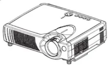
Your projector should come with the items shown below. Check to make sure that all the items are included. Contact your dealer if anything is missing.
NOTE • Keep the original packing material for future reshipment.
natural_image
Line drawing of a projector with control panel and lens (no text or symbols)Projector (with Lens Cap)
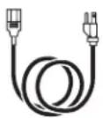
Power cord (US Type)
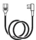
Power cord (UK Type)
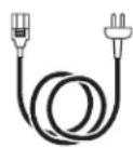
Power cord (Europe Type)
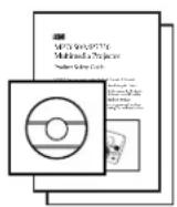
Operator's Guide
Product Safety Guide
Warranty
Quick Start Guide
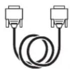
RGB cable
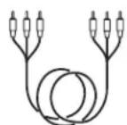
Video/Audio
cable
(with white lead)
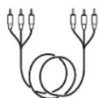
Component Video cable
(with green lead)
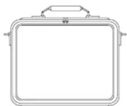
natural_image
Line drawing of a rectangular container with handles and a handle (no text or symbols)Soft carrying case

USB mouse
cable
Two AA batteries
(for the remotecontrol)
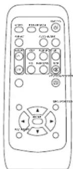
Remote control
WARNING Precautions to observe in regards to the power cord: Please use extra caution when connecting the projector's power cord as incorrect or faulty connections may result in FIRE AND/OR ELECTRICAL SHOCK. Please adhere to the following safety guidelines to insure safe operation of the projector:
- Only plug the power cord into outlets rated for use with the power cord's specified voltage range.
- Only use the power cord that came with the projector.
- NEVER ATTEMPT TO DEFEAT THE GROUND CONNECTION OF THE THREE-PRONGED PLUG!
- Make sure that you firmly connect the power cord to the projector and wall outlet.
1 Connect your devices to the projector
Connect your computer, VCR and/or other devices you will be using to the projector.
8 \~ 12
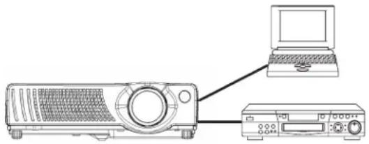
natural_image
Line drawing of a projector connected to a laptop and a CD (no text or symbols)2 Insert the batteries into the remote control
13
natural_image
Technical line drawing of a remote control casing with mounting holes and indicator lights (no text or symbols)3 Connect the power cord
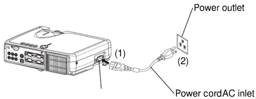
(1) Connect the connector of the electrical power cord to the AC inlet of the main unit.
(2) Firmly plug the power cord's plug into the outlet
NAMES OF PARTS
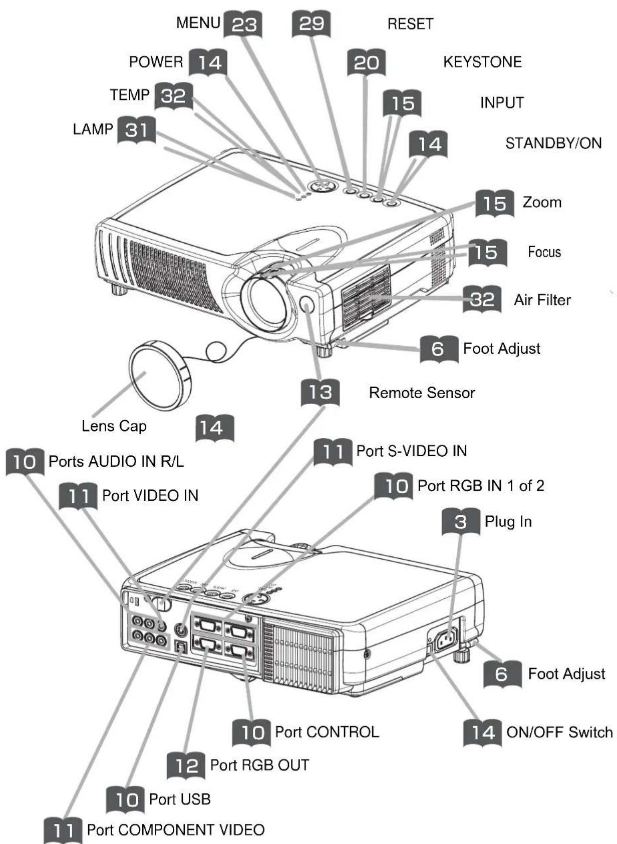
The Projector
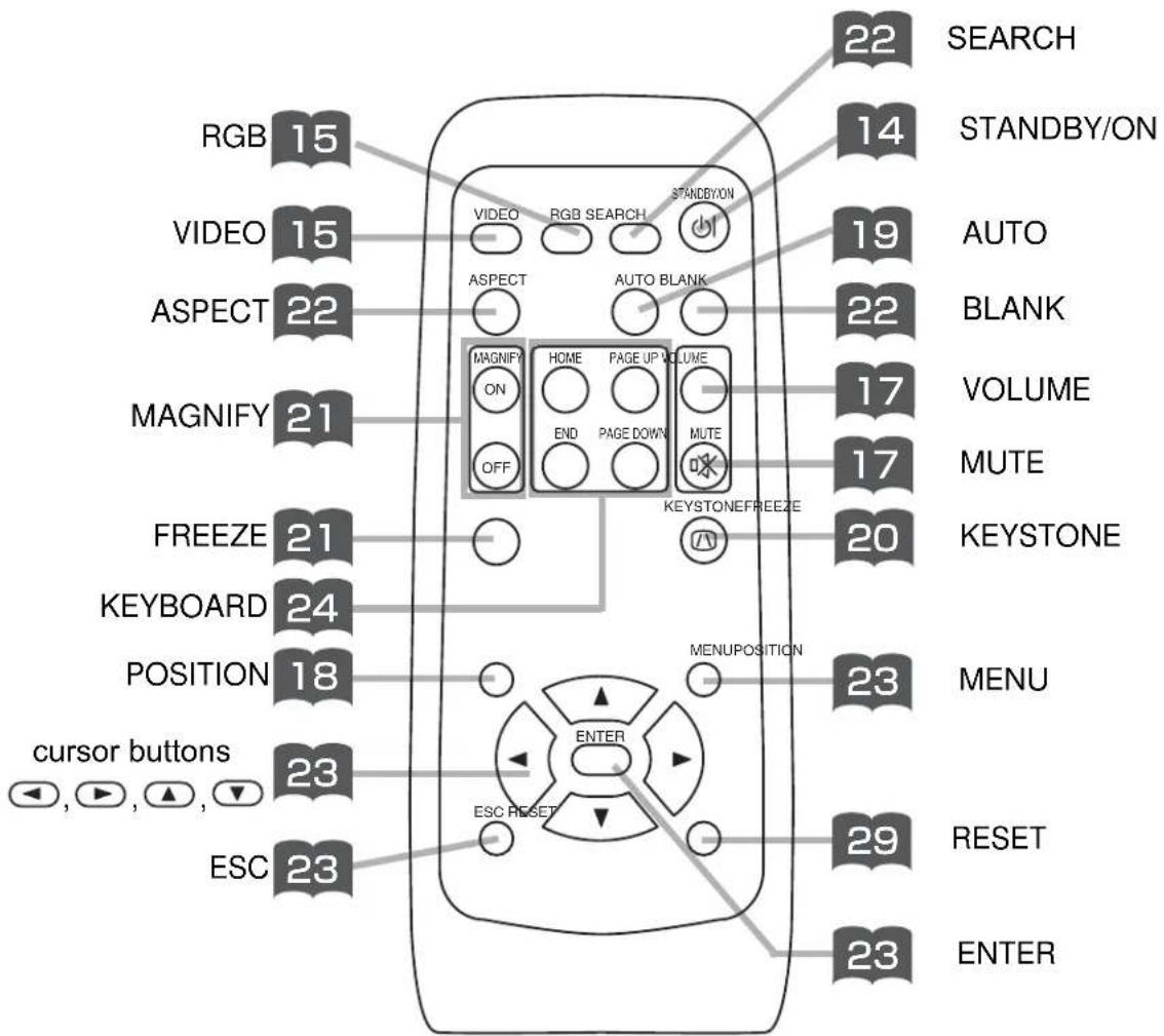
THE REMOTE CONTROL
SETTING UP THE PROJECTOR

CAUTION • Install the projector in a suitable environment according to instructions of the "Product Safety Guide" and this "Operator's Guide".
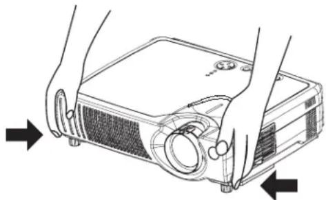
- If you press the elevator buttons without holding the projector, the projector might crash down, overturn, smash your fingers and possibly result in malfunction. To prevent damaging the projector and injuring yourself, ALWAYS HOLD THE PROJECTOR whenever using the elevator buttons to adjust the elevator feet.
Adjusting the Projector's Elevator Feet
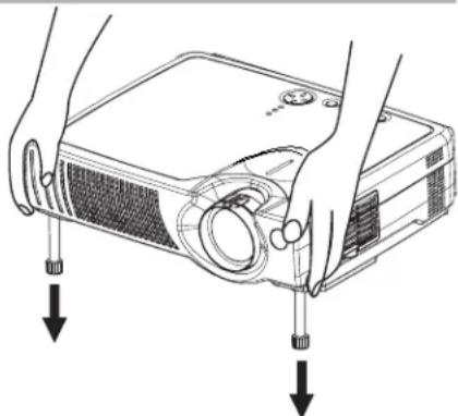
You can use the elevator feet to make adjustments if the surface on which you need to set the projector is uneven or if you otherwise need to adjust the angle of projection. The adjustment range of the elevator feet is 0 to 9 degrees.
1
Press and hold in the elevator buttons
natural_image
Illustration of hands operating a projector case with arrows indicating direction (no text or symbols)2
Raise or lower the projector to the desired height and then release the elevator buttons
When you release the elevator buttons, the elevator feet will lock into position.
natural_image
Illustration of hands installing a projector module with two arrows indicating the process (no text or symbols present)3
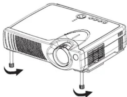
As necessary, you can also finely adjust the height of the projector by twisting the elevator feet by hand
natural_image
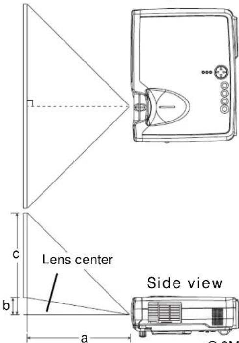
Line drawing of a projector with directional arrows indicating motion (no text or symbols)Adjusting the Screen Size and Projection Distance
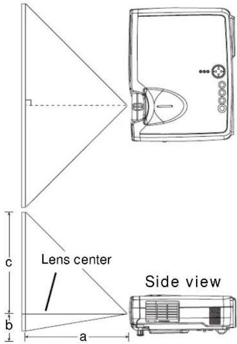
Refer to the illustrations and tables below to determine the screen size and projection distance.
The values shown in the table are calculated for a full size screen
(MP7650: 800x600 pixels / MP7750: 1024x768 pixels).
a:Distance from the projector to the screen (±10%)
b:Distance from the lens center to the bottom of the screen (±10%)
c:Distance from the lens center to the top of the screen (±10%)
The screen
Top view
If 4:3 aspect ratio
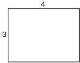
| Screen Size [inch (m)] | a [inch (m)] | b[inch (cm)] | c[inch (cm)] | |
| Min. Max. | ||||
| 30 (0.8) 35 (0.9) | 42 (1.1) 1 | (2) 17 (44) | ||
| 40 (1.0) 47 (1.2) | 56 (1.4) 1 | (3) 23 (58) | ||
| 50 (1.3) 59 (1.5) | 71 (1.8) 1 | (4) 29 (73) | ||
| 60 (1.5) 71 (1.8) | 85 (2.2) 2 | (4) 34 (87) | ||
| 70 (1.8) 83 (2.1) | 100 (2.5) | 2 (5) 40 (102) | ||
| 80 (2.0) 95 (2.4) | 114 (2.9) | 2 (6) 46 (116) | ||
| 90 (2.3) | 107 (2.7) | 129 (3.3) | 3 (7) 51 (131) | |
| 100 (2.5) | 119 (3.0) | 143 (3.6) | 3 (7) 57 (145) | |
| 120 (3.0) | 143 (3.6) | 172 (4.4) | 3 (9) 69 (174) | |
| 150 (3.8) | 180 (4.6) | 216 (5.5) | 4 (11) 86 (218) | |
| 200 (5.0) | 240 (6.1) | 288 (7.3) | 6 (15) 114 (290) | |
| 250 (6.3) | 300 (7.6) | 361 (9.2) | 7 (18) 143 (363) | |
| 300 (7.5) | 360 (9.2) | 433 (11.0) | 9 (22) 171 (435) | |
The screen
Top view
If 16:9 aspect ratio
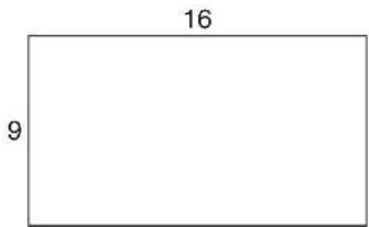
| Screen Size [inch (m)] | a [inch (m)] | b[inch (cm)] | c[inch (cm)] | |
| Min. Max. | ||||
| 30 (0.8) 38 (1.0) | 46 (1.2) 2 | (4) 16 (41) | ||
| 40 (1.0) 51 (1.3) | 61 (1.6) 2 | (5) 22 (55) | ||
| 50 (1.3) 64 (1.6) | 77 (2.0) 3 | (6) 27 (69) | ||
| 60 (1.5) 77 (2.0) | 93 (2.4) 3 | (8) 32 (82) | ||
| 70 (1.8) 90 (2.3) | 109 (2.8) | 4 (9) 38 (96) | ||
| 80 (2.0) | 104 (2.6) | 125 (3.2) | 4 (10) 43 (110) | |
| 90 (2.3) | 117 (3.0) | 140 (3.6) | 5 (12) 49 (124) | |
| 100 (2.5) | 130 (3.3) | 156 (4.0) | 5 (13) 54 (137) | |
| 120 (3.0) | 156 (4.0) | 188 (4.8) | 6 (15) 65 (165) | |
| 150 (3.8) | 196 (5.0) | 235 (6.0) | 8 (19) 81 (206) | |
| 200 (5.0) | 261 (6.6) | 314 (8.0) | 10 (26) | 108 (275) |
| 250 (6.3) | 327 (8.3) | 393 (10.0) | 13 (32) | 135 (343) |
| 300 (7.5) | 393 (10.0) | 472 (12.0) | 15 (39) | 162 (412) |
CONNECTING YOUR DEVICES
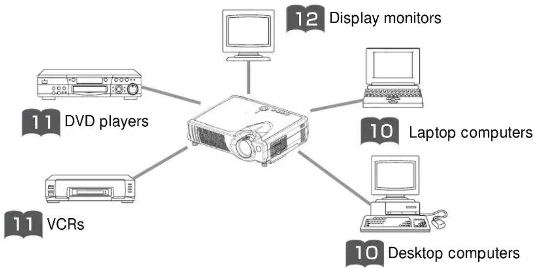
Devices You Can Connect to the Projector (Refer to this section for planning your device configuration to use for your presentation.)

CAUTION • Incorrect connecting could result in fire or electrical shock. Please read the "Product Safety Guide" and this "Operator's Guide".
ATTENTION Precautions to observe when connecting other devices to the projector
- Whenever attempting to connect other devices to the projector, please thoroughly read the manual of each device to be connected.
- TURN OFF ALL DEVICES prior to connecting them to the projector. Attempting to connect a live device to the projector may generate extremely loud noises or other abnormalities that may result in malfunction and/or damage to the device and/or projector. Refer to the “TECHNICAL” for the pin assignment of connectors and RS-232C communication data.
- Make sure that you connect devices to the correct port. Incorrect connection may result in malfunction and/or damage to the device and/or projector.
- A component cable and some other cables have to be used with core set. Use the accessory cable or a designated-type cable for the connection. For cables that have a core only at one end, connect the core to the projector.
- Secure the screws on the connectors and tighten.

Indicates the corresponding reference page
flowchart
graph TD
    A["Central Unit"] --> B["12 Display monitors"]
    A --> C["10 Laptop computers"]
    A --> D["10 Desktop computers"]
    A --> E["11 VCRs"]
    A --> F["11 DVD players"]
Ports and Cables
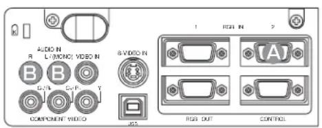
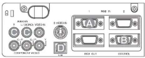
Refer to the table below to find out which projector port and cable to use for connecting a given device. Use this table for determining which cables to prepare.
| Function Projector Port Connection Cables | ||
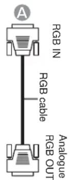
| RGB input | RGB IN 1 | RGB cable with D-sub 15-pin shrink jack and inch thread screws |
| RGB IN 2 | ||
| RGB output RGB OUT | ||
| USB mouse control USB USB cable | ||
| PS/2 mouse control | cableCONTROLe cable | PS/2 mouse cable |
| ADB mouse control ADB mouse | ||
| Serial mouse control Serial mouse | ||
| RS-232C communication RS-232C cable | ||
| S-video input S-VIDEO IN | S-video cable with mini DIN 4-pin jack | |
| Video input VIDEO IN Audio/video cable | ||
| Component video input | COMPONENT VIDEO Y | Component video cableCOMPONENT VIDEO |
| _B/P_B | ||
| COMPONENT VIDEO C_R/P_R | ||
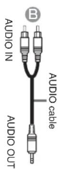
| Audio input | AUDIO IN L | Audio/video cableor Audio cable with RCA jack |
| AUDIO IN R | ||
NOTE About Plug-and-Play Capability
- This projector is compatible with VESA DDC 1/2B. Plug-and-Play can be achieved by connecting this projector to computers that are VESA DDC (display data channel) compatible. Please take advantage of this function by connecting the accessory RGB cable to the RGB IN 1 port (DDC 1/2B compatible). Plug-and-Play may not work properly if any other type of connection is attempted.
- Plug-and-Play is a system composed of the computer, its operating system and peripheral equipment (i.e. display devices).
- Please use the standard drivers as this projector is a Plug-and-Play monitor.
- Plug-and-Play may not function properly with some type of computers. Use the RGB IN 2 port if Plug-and-Play does not function correctly.
CONNECTING YOUR DEVICES (continued)
Connecting to a Computer
ATTENTION Whenever attempting to connect a laptop computer to the projector, be sure to activate the laptop's RGB external image output (set the laptop to CRT display or to simultaneous LCD and CRT display). For details on how this is done, please refer to the instruction manual of the corresponding laptop computer.

natural_image
Line drawing of a laptop computer with front panel and keyboard (no text or symbols)Laptop computer
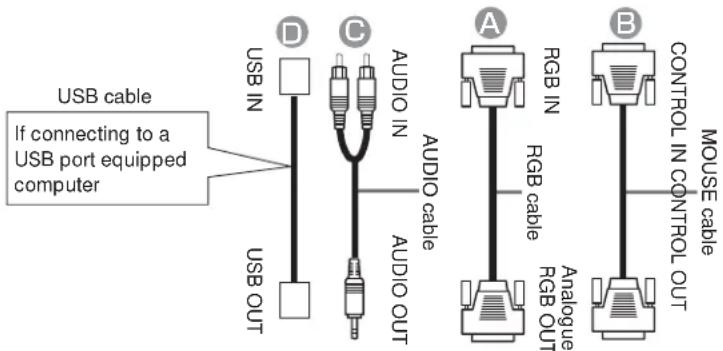

Desktop computer
NOTE
- Some computers may have multiple display screen modes. Use of some of these modes will not be possible with this projector.
- For some RGB input modes, the optional Mac adapter is necessary.
Connecting to a DVD Player
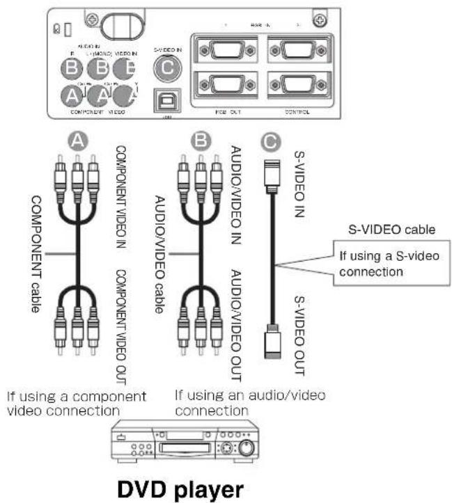
Connecting to a VCR
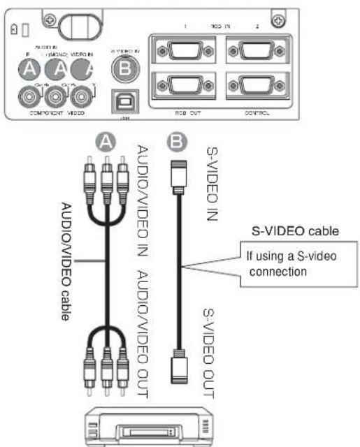
VCR
CONNECTING YOUR DEVICES (continued)
Connecting to a Display Monitor
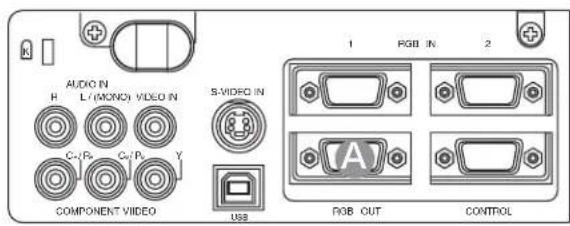
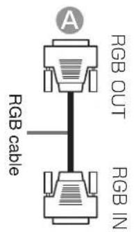
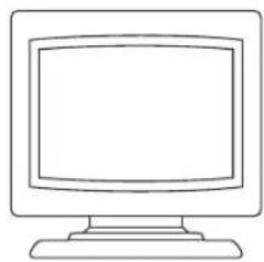
natural_image
Line drawing of a flat-screen computer monitor (no text or symbols)Display monitor
USING THE REMOTE CONTROL
Putting batteries into the remote control unit

CAUTION Precautions to observe in regards to the batteries
Always handle the batteries with care and use them only as directed. Improper use may result in battery cracking or leakage, which could result in fire, injury and/or pollution of the surrounding environment.
- Keep the battery away from children and pets.
- Be sure to use only the batteries specified for use with the remote control. Do not mix new batteries with used ones.
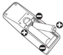
- When inserting batteries, verify that the plus and minus terminals are aligned correctly (as indicated in the remote control).
- When you dispose the battery, you should obey the law in the relative area or country.
1
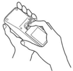
Remove the battery cover Slide back and remove the battery cover in the direction of the arrow.
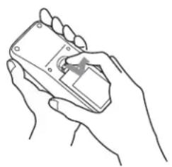
natural_image
Line drawing of a hand holding a handheld device (no text or symbols visible)2
Insert the batteries Align and insert the two AA batteries (that came with the projector) according to their plus and minus terminals (as indicated in the remote control).
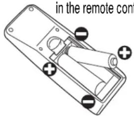
3
Close the battery cover Replace the battery cover in the direction of the arrow and snap it back into place.
natural_image
Line drawing of two hands holding a handheld device (no text or symbols)Operating the remote control
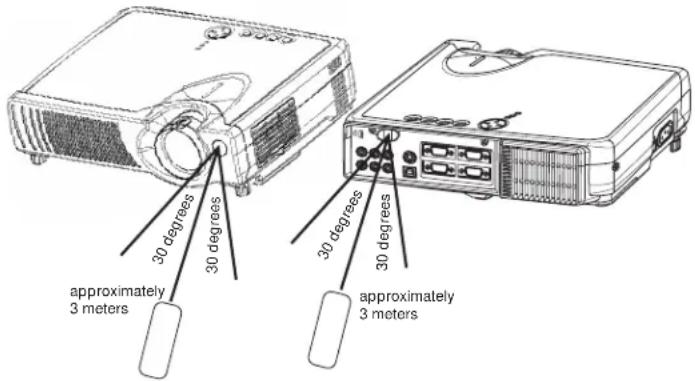
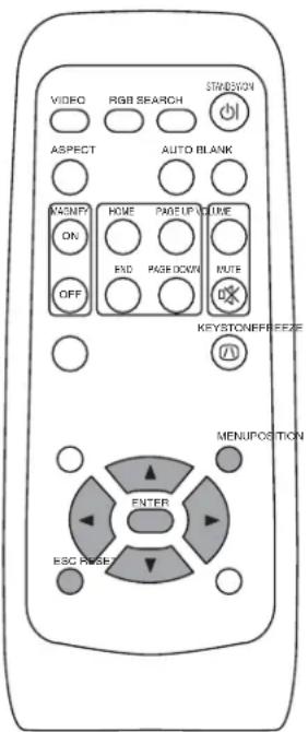
- The remote control works with both the projector's front and rear remote sensors.
- The range of the remote sensor on the front and back is 3 meters with a 60-degree range (30 degrees to the left and right of the remote sensor).
- Since the remote control uses infrared light to send signals to the projector (Class 1 LED), be sure to use the remote control in an area free from obstacles that could block the remote control's output signal to the projector.
ATTENTION
Precautions to observe when using the remote control
- Do not drop or otherwise expose the remote control to physical impact.
- Do not get the remote control wet or place it on wet objects. Doing so may result in malfunction.
- Remove the batteries from the remote control and store them in a safe place if you won't be using the remote control for an extended period.
- Replace the batteries whenever the remote control starts to malfunction.
- When strong light, such as direct sunlight or light from an extremely close range (such as from an inverter fluorescent lamp), hits the projector's remote sensor, the remote control may cease to function. Adjust the direction of the projector to keep light from directly hitting the projector's remote sensor.
Connect all devices to be used to the projector prior to turning on the power.


WARNING When the power is ON, a strong light is emitted. Do not look into the lens.
Control panel
NOTE Turn the
power on/off in right order.
• Power on the projector before the computer or video tape recorder.
• Power off the projector after the computer or video tape recorder.
1
Make sure that the power cord is firmly and correctly connected to the projector and outlet

2
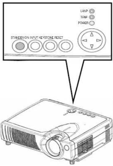
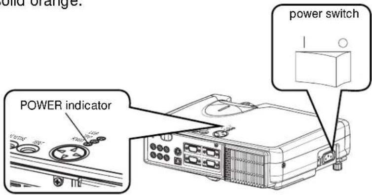
Turn on the projector's power Set the power switch to [ | ] (ON). The projector will go to STANDBY mode and the POWER indicator will light to solid orange.
3
Press the STANDBY/ON button (control panel or remote control)
- The projector begins warming up and the POWER indicator blinks green.
- The POWER indicator stops blinking and lights to solid green once the projector's power is completely on.
4
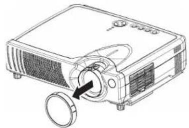
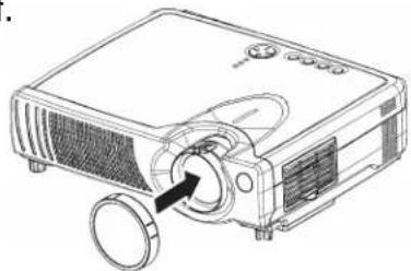
Remove the lens cap
The picture is projected.
natural_image
Line drawing of a projector with a circular button and control panel (no text or symbols)Selecting an Input Signal
5
Using the remote control
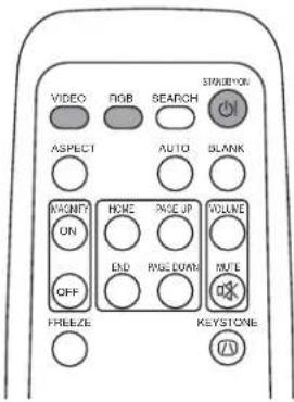
If selecting RGB input Press the RGB button Press this button to toggle between the devices connected to RGB IN 1 and 2. As illustrated below, each time you press the RGB button, the projector switches between RGB IN 1 and 2. Select the signal you wish to project.
RGB IN 1 RGB IN 2
If selecting video input Press the VIDEO button Press this button to toggle between the devices connected to VIDEO IN, S-VIDEO IN and COMPONENT VIDEO. As illustrated below, each time you press the VIDEO button, the projector switches between VIDEO IN, S-VIDEO IN and COMPONENT VIDEO. Select the signal you wish to project.

Using the projector's control panel
Press the INPUT button As illustrated below, each time you press the INPUT button, the projector switches between its input signal ports. Select the signal you wish to project.

RGB IN 1 RGB IN 2 VIDEO IN
flowchart
graph TD
    A["S-VIDEO INCOMPONENT"] --> B["↓"]
    B --> C["←"]
6
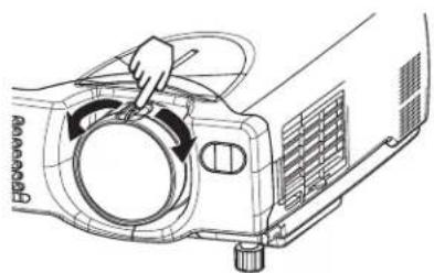
Use the zoom ring to adjust the screen size
natural_image
Line drawing of a projector with a hand adjusting the lens (no text or symbols)7
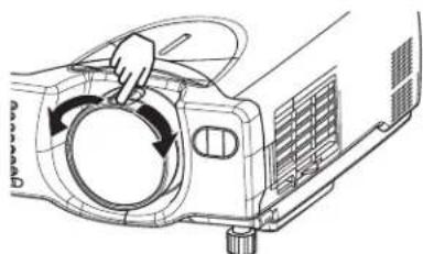
Use the focus ring to focus the picture
natural_image
Diagram of a car air conditioner unit with hand operating the valve (no text or symbols)- Except in emergencies, follow the above-mentioned procedure for turning power off.
1
Press the STANDBY/ON button (control panel or remote control)
The message "Power off?" will appear on the screen for approximately 5 seconds.
STANDBY:ON

2
Press the STANDBY/ON button again (control panel or remote control)
Press the STANDBY/ON button again while the "Power off?" message is visible. The projector lamp goes off and starts cooling down. The POWER indicator blinks orange while the lamp cools down. (Pressing the STANDBY/ON button while the POWER indicator is blinking orange has no effect.)
The system goes into the STANDBY mode after cooling down and the POWER indicator stops blinking orange and then lights to solid orange.
3
Check that the POWER indicator stops blinking and lights to solid orange.
Switch the power switch to [O] (OFF).
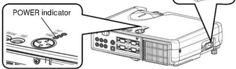
4
Confirm that the POWER indicator has gone off and then attach the lens cap. When the projector has completed powering down, the POWER indicator will go off.
natural_image
Line drawing of a projector with a circular dial and control knob (no text or symbols)ADJUSTING THE VOLUME
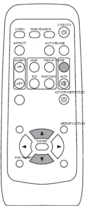
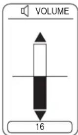
1 Press the VOLUME button
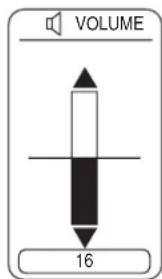
As illustrated on the right, a dialog will appear on the screen to aid you in adjusting the volume.

ENSOLIDSH
2 Press the ,buttons to adjust the volume
Press the VOLUME button again to close the dialog and complete this operation. (Even if you don't do anything, the dialog will automatically disappear after a few seconds.)

▲ Press this to increase the volume
▼ Press this to decrease the volume
TEMPORARILY MUTING THE SOUND
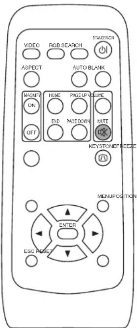
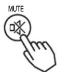
1 Press the MUTE button
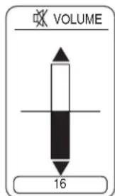
As illustrated on the right, a dialog will appear on the screen indicating that you have muted the sound. Press the VOLUME button to close the dialog. (Even if you don't do anything, the dialog will automatically disappear after a few seconds.)
Press the MUTE button again to restore the sound.
As illustrated on the right, a dialog will appear on the screen to aid you in adjusting the position.

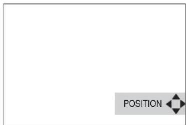
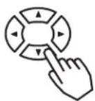
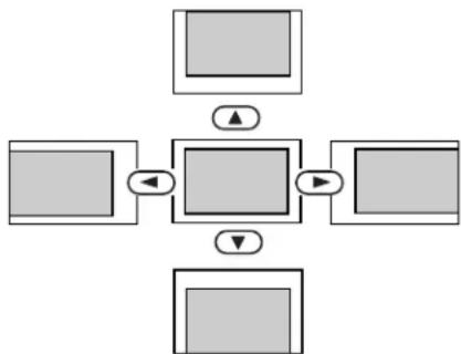
2 Use the ◀, ▶, ▲, ▼ buttons to adjust the position
When you want to initialize the position, press the RESET button during adjustment.
Press the POSITION button again to close the dialog and complete this operation. (Even if you don't do anything, the dialog will automatically disappear after a few seconds.)
This function is only available for RGB IN 1/2 input.
flowchart
graph TD
    A["Input 1"] --> C["Process"]
    B["Input 2"] --> C
    D["Input 3"] --> C
    E["Input 4"] --> C
    C --> F["Output"]
    style C fill:#f9f,stroke:#333,stroke-width:2px
USING THE AUTOMATIC ADJUSTMENT FEATURE
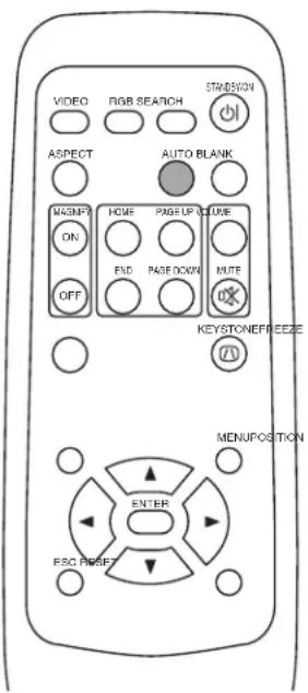
1
Press the AUTO button

Automatic Adjustment for RGB Input
Horizontal position (H. POSIT), vertical position (V. POSIT), clock phase (H. PHASE) and horizontal size (H. SIZE) are automatically adjusted. Make sure that the application window is set to its maximum size prior to attempting to use this feature. Dark pictures may still be incorrectly adjusted. Use a bright screen when adjusting.
Automatic Adjustment for Video Input
The signal type best suited for the respective input signal is selected automatically. This feature is available only if VIDEO is set to AUTO in the INPUT menu.
NOTE
The automatic adjustment operation requires approximately 10 seconds. Also, please note that it may not function correctly with some input signals.
CORRECTING KEYSTONE DISTORTIONS
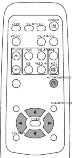
1
Press the KEYSTONE button
As illustrated on the right, a dialog will appear on the screen to aid you in correcting the distortion.
KEYSTONE

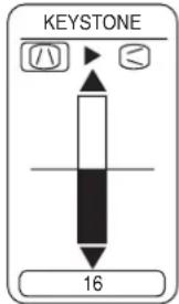
2
Use the ,buttons to select the
direction of distortion to correct (A)

3
Use the , buttons to correct the
distortion
Press the KEYSTONE button again to close the dialog and complete this operation. (Even if you don't do anything, the dialog will automatically disappear after a few seconds.)

NOTE
- This function may not be work well with some types of input signals.
- The adjustable range for correcting keystone distortions will vary with the type of input signal.
USING THE MAGNIFY FEATURE
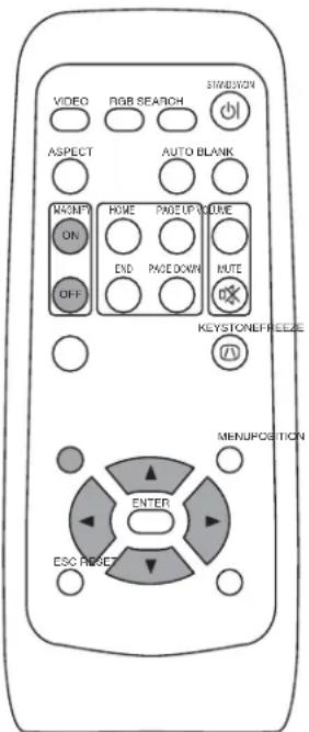
1 Press the MAGNIFY (ON) button The projector enters MAGNIFY mode.

2 Press the POSITION button, then use the ,◀ ,▶ ▲ , buttons to select the area to enlarge and then press the POSITION button again to confirm your selection

flowchart
graph LR
    A["Position"] --> B((Circular Button)) --> C["Position"]
3 Press the buttons to zoom in and out of the selected area. Press the MAGNIFY (OFF) button to exit MAGNIFY mode and restore the screen to normal. (The projector will also automatically exit MAGNIFY mode if there is a change in the input signal's state.)

NOTE
The projector will automatically exit from MAGNIFY mode if either the INPUT SELECT, AUTO, ASPECT or VIDEO feature is used, or, if there is a change in the input signal's state.
FREEZING THE SCREEN
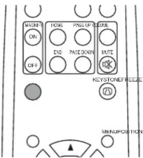
1 Press the FREEZE button The [II] icon appears and the screen will freeze at the current image. Press the FREEZE button again and the [▶] appears as the projector exits FREEZE mode.

NOTE
- The projector will automatically exit from FREEZE mode if either the POSITION, VOLUME, MUTE, AUTO, BLANK ON/OFF or MENU ON/OFF feature is used, or, if there is a change in the input signal's state.
- If the projector continues projecting the same image for a long time (i.e. you forget to exit FREEZE mode), the image might possibly remain as an afterimage. Do not leave the projector in FREEZE mode for too long.
© 3M 2002. All Rights Reserved.
SIGNAL SEARCHING
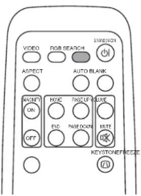
1 Press the SEARCH button
When you press the SEARCH button, the projector begins searching for input signals. If it detects an input signal, the search will cease and the projector will project the detected signal. If the projector is unable to find an input signal at any of its ports, it will return to the state it was in prior to the search.

flowchart
graph TD
    A["COMPONENT VIDEO"] --> B["RGB IN 1-RGB IN 2 VIDEO IN"]
    B --> C["S-VIDEO IN"]
    D["SEARCH"] --> A
SELECTING THE ASPECT RATIO
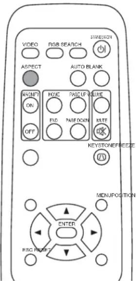
1 Press the ASPECT button

RGB IN 1, RGB IN 2, COMPONENT VIDEO
(HDTV signals : 1125i (1035i/1080i), 750p)
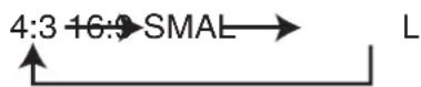
4:3 16:0
VIDEO IN, S-VIDEO IN, COMPONENT VIDEO
(Non-HDTV signals : 525i, 525p,625i)
TEMPORARILY BLANKING THE SCREEN
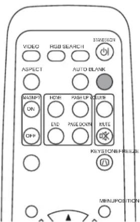
1 Press the BLANK button
The input signal screen is shut off, and a blank screen appears. You can set the blank screen using the menu (from the SCREEN menu, select BLANK). Press the BLANK button again to remove the blank screen, and return to the input signal screen.

USING THE MENU FUNCTIONS
1
Press the MENU button
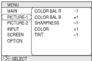
The menu display appears on the screen. The projector has the following menus: MAIN, PICTURE 1, PICTURE 2, INPUT, SCREEN, and OPTION. Select a menu using the /buttons. The current settings of the items that can be manipulated via the selected menu appear.

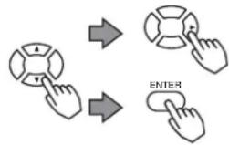
2
Select a menu using the ▲/▼ buttons, then press the o▶ENTER button.
The display of the selected menu appears.
[ex. Adjusting SHARPNESS]
Use the /buttons to select PICTURE 1, then press the or ENTER button.
flowchart
graph TD
    A["Switch A"] --> B["Switch B"]
    B --> C["ENTER"]
3
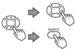
Select an item using the ▲/▼ buttons, then press the ▶ or ENTER button.
The operation display of the selected item appears. To adjust a numerical value, press the OR ENTER button again to switch to the single menu (small display showing only the operation display area).
[ex. Adjusting SHARPNESS]
Use the /buttons to select SHARPNESS, then press the or ENTER button.
flowchart
graph TD
    A["User Hand Icon"] --> B["Arrow to Left"]
    B --> C["Arrow to Right"]
    C --> D["Arrow to Bottom"]
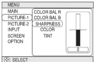
4
Press the ▲/▼ buttons to adjust the level.
Press the MENU button to hide the menu and finish your operation. Alternatively, press the or ESC button to return to the previous display.
[ex. Adjusting SHARPNESS]
Use the /buttons to adjust the SHARPNESS.
MULTIFUNCTIONAL SETTINGS
This device has 6 separate menus: MAIN, PICTURE 1, PICTURE 2, INPUT, SCREEN, OPTION. Each of these menus is operated using the same methods. The basic operations of these menus are as follows.
Menu screen display : Press the MENU button.
Menu selection : Choose a menu name using the ▲ /▼ button, and press the ▶ button or the ENTER button.
Item selection : Choose an item using the ▲ /▼ button, and press the ▶ button or the ENTER button.
Return menu to last previous screen: Press the ↕ button or the ESC button.
Execution of settings and/or adjustments: Operate by using the button (For further details, read the explanation for each separate menu.)
Initialization of settings and/or adjustments: During operation, press the RESET button. (Note that items whose functions are performed simultaneously with the operation of clock phase, language selection, automatic adjustment, etc., cannot be initialized.)
End menu operations: Press the MENU button, or do not perform any operation for several seconds.
MAIN Menu
With the MAIN menu, the seven items shown in the Table below can be performed.
Perform each operation in accordance with the instructions in the Table.
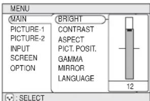
Example : MAIN Menu (BRIGHT)
MAIN Menu
| Item Description | |
| BRIGHT | Adjust Brightness: Light Dark ⇔ ▼ |
| CONTRAST | Adjust Contrast: Strong Weak ⇔ ▼ |
| ASPECT | Select Aspect Ratio:At RGB Input or Hi-Vision 1125i(1035i/1080i)/750p of COMPONENT VIDEO Input:4:3 ▼ ⇔ ▲ 16:9At VIDEO Input, S-VIDEO Input or 525i/525p/625i of COMPONENT VIDEO Input:4:3 16:9 SMALL ▼ ⇔ ▲The SMALL picture may not be displayed correctly with certain input signals. |
| PICT.POSIT. | Select Picture Position (for 16:9/SMALL Picture):TOP ▼ ⇔ ▲ CENTER BOTTOM |
| GAMMA | Select Gamma Mode:NORMAL ▼ ⇔ ▲ CINEMA DYNAMIC |
| MIRROR | Select Mirror Status:NORMAL ▼ ⇔ ▲ H:INVERT WINVERT H&V:INVERT ⇔ ▲ |
| LANGUAGE | Select Menu Language:ENGLISH ▼ ⇔ ▲ FRAN AIS DEUTSCHESPA OL ▼ ⇔ ▲▼ ⇔ ▲ ITALIANO NORSKEDERLANDS ⇔ ▲ ▼ ⇔ ▲日本語 ▲ ⇔ ▼ POTUGU S ▼ ⇔ ▲ 中文 ▼ ⇔ ▲ 한글 |
PICTURE 1 Menu
With the PICTURE 1 menu, the five items shown in the Table below can be performed.
Perform each operation in accordance with the instructions in the Table.
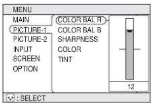
Example : PICTURE1 Menu (COLOR BAL R)
PICTURE1 Menu
| Item Description | |
| COLOR BAL R | Adjust Red Color Balance: Dark Light ⇔▼ |
| COLOR BAL B | Adjust Blue Color Balance: Dark Light ⇔▼ |
| SHARPNESS | Adjust Sharpness (for VIDEO/S-VIDEO): Clear Soft ⇔▼ |
| COLOR | Adjust COLOR (for VIDEO/S-VIDEO/COMPONENT VIDEO): Dark ▲ ⇔▼ Light |
| TINT | Adjust Tint (for VIDEO/S-VIDEO): Green Red ▲ ⇔▼ |
PICTURE 2 Menu
With the PICTURE 2 menu, the five items shown in the Table below can be performed.
Perform each operation in accordance with the instructions in the Table.
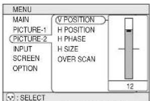
Example : PICTURE2 Menu (V POSITION)
PICTURE2 Menu
| Item Description | |
| V POSITION | Adjust Vertical Position (for RGB): Up Down ⇔ ▼ |
| H POSITION | Adjust Horizontal Position (for RGB): Left Right ⇔ ▼ |
| H PHASE | Adjust Horizontal Phase (for RGB/COMPONENT VIDEO):Right ▲ ⇔ ▼ Left• Adjust to eliminate flicker. |
| H SIZE | Adjust Horizontal Size (for RGB): Large Small ⇔ ▼• If the horizontal size adjustment is excessive, the image may not be displayed correctly. In such a case, initialize H SIZE with the RESET button. |
| OVER SCAN | Select Over-scan Ratio (for VIDEO/S-VIDEO/COMPONENT VIDEO):LARGE ▼ ⇔ ▲ MIDDLE SMALL ▲• It is recommended to select SMALL to avoid flicker at the lower part of the picture. |
MULTIFUNCTIONAL SETTINGS (continued)
INPUT Menu
With the INPUT menu, the four items shown in the Table below can be performed. With inputting of RGB IN 1 and RGB IN 2 signals, the horizontal and vertical frequencies of the signals will be displayed on the initial screen of the INPUT menu.
Perform each operation in accordance with the instructions in the Table.
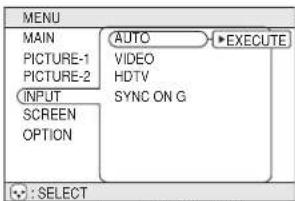
Example : INPUT Menu (AUTO)
INPUT Menu
| Item Description | |
| AUTO | Auto Adjust (for RGB): Automatically adjusts H POSITION, V POSITION, H PHASE, and H SIZE. Use this function with the maximum window size.Auto Adjust (for VIDEO/S-VIDEO): Automatically selects the proper VIDEO mode for the current input signal. This function is active only when the AUTO mode is selected for the item VIDEO. Refer to the description for the item VIDEO below.This function may not be available with a PAL60 signal and certain other signals.The AUTO mode operation requires approximately 10 seconds.For COMPONENT VIDEO, the signal type is identified automatically even if this function is inactive. For a HDTV signal, refer to the item HDTV below. |
| VIDEO | Select Mode of Signal Type (for VIDEO/S-VIDEO):AUTO ⇔ NTSC PAL SECAMNTSC4.43 M.PAL-N.PAL Selecting AUTO mode activates and performs the AUTO function for VIDEO/S-VIDEO. It automatically selects the proper mode from among those above. Use this function if the image becomes unstable with VIDEO/S-VIDEO. (e.g. The image becomes irregular, or lacks color.)AUTO mode may not function correctly with a PAL60 signal and certain other signals.The AUTO mode operation requires approximately 10 seconds.For COMPONENT VIDEO, the signal type is identified automatically even if this function is inactive. For a HDTV signal, refer to the item HDTV below. |
| HDTV | Select HDTV Signal Mode:1080i ⇔ 1035iIf the selected HDTV mode is incompatible with the input signal, the picture may be distorted. |
| SYNC ON G | On/Off SYNC ON G Mode:TURN ON ⇔ TURN OFFSelecting TURN ON turns on the SYNC ON G mode. The SYNC ON G mode allows reception of SYNC on G.In the SYNC ON G mode, the picture may be distorted with certain input signals. In such a case, remove the signal connector so that no signal is received and turn SYNC ON G off, and then reconnect the signal. |
SCREEN Menu
With the SCREEN menu, the five items shown in the Table below can be performed. Please perform each operation in accordance with the instructions in the Table.
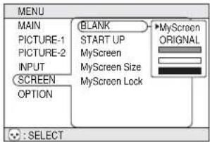
Example : SCREEN Menu (BLANK)
SCREEN Menu
| Item Description | |
| BLANK | Selection of BLANK Screen:MyScreen ORIGINAL. The BLANK Screen may be voluntarily selected. The BLANK Screen is displayed when the screen has been erased (i.e., made to vanish) by manipulating the BLANK button (please refer to the "Temporarily Blanking the Screen" section of the separate booklet, Vol. 1 (Basic)).MyScreen: Using the MyScreen category (see this Table, below), one can register a desired screen (or screens). At the time of factory shipment, this is set as a non-patterned (plain) blue color screen.ORIGINAL: Existing standard screens. Please make confirmation using the actual screen(s).Option screens: Various colored non-patterned (plain) screens displayed within the Menus.• The MyScreen and the ORIGINAL Screen will each change to a non-patterned (plain) black color screen several minutes after being displayed. |
| START UP | Selection of START UP Screen:MyScreen ORIGINAL TURN OFF The START UP Screen may be voluntarily selected. The START UP Screen is displayed when no signal has been inputted, or when spec signals are being inputted.MyScreen: Using the MyScreen category (see this Table, below), one can register a desired screen (or screens). At the time of factory shipment, this is set as a non-patterned (plain) blue color screen.ORIGINAL: Existing standard screens. Please make confirmation using the actual screen(s).TURN OFF: A non-patterned (plain) blue color screen.• The MyScreen and the ORIGINAL Screen will each change to the BLANK Screen several minutes after being displayed. |
| MyScreen | Registration of MyScreen:When this item is executed, the MyScreen Menu for registration of MyScreen for the BLANK Screen and the START UP Screen is displayed. When operations are performed in accordance with this Menu, one can "cut" and register desired screens from among the received images within the display.1. After the "Do you start capturing this picture?" message has been displayed, pressing the ESC (or RESET) button interrupts execution of the MyScreen. When the ENTER button is pressed, the picture becomes static (no longer moves), and a frame for picture cutting, as well as the message that follows below, appear. Please press the button when the screen you want to register is currently being displayed.2. When the "Move the capture area as you want." message has been displayed, pressing the ESC (or RESET) button will eliminate the static state of the picture, and operations can be performed again from operation 1.The frame can be moved using the button. After designating the screen you want to register, pressing the ENTER button will initiate screen registration. The registration process takes approximately 1 minute to complete.3. When the registration has been completed, the screen of the registered MyScreen, plus the message, "MyScreen registration is finished," will be displayed for several seconds, after which the operation is terminated. |
| MyScreen Size | Selection of MyScreen display size:x1 FOL ⇔ ▲ |
| MyScreen Lock | Invalidation of MyScreen registration function:TURN ON TURN OFFWhen TURN ON is selected, the MyScreen category (see this Table, above) cannot be executed; in this way, one can prohibit rewrites ("writeovers") of the MyScreen. |
MULTIFUNCTIONAL SETTINGS (continued)
OPTION Menu
With the OPTION menu, the five items shown in the Table below can be performed.
Please perform each operation in accordance with the instructions in the Table.
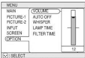
Example : OPTION Menu (VOLUME)
OPTION Menu
| Item Description | |
| VOLUME | Adjust Volume: High Low ⇔ ▼ |
| AUTO OFF | Adjust AUTO OFF Time:Long (MAX. 99 min.) Short(Min.1 min.) (DISABLE: 0min.)→▲The system automatically enters the standby mode if no signal is received within the set time. This function is inactive when DISABLE (0 min.) is selected. |
| WHISPER | Select WHISPER Mode:NORMAL ⇌ ▲ WHISPERWhen WHISPER is selected the WHISPER mode is activated. In the WHISPER mode, acoustic noise and screen brightness are reduced. |
| LAMP TIME | Refer to LAMP TIME: When set, this function displays the total time the projector lamp has been used since new.Reset LAMP TIME [Use this function only when the lamp has been replaced!]:Depress the RESET button for at least 3 seconds while lamp time is being displayed. The reset menu will then appear. After you replace the lamp with a new lamp, select RESET on the menu with the button.Do not reset the lamp time unless you have replaced the lamp. And, always reset the lamp time when replacing the lamp. The message functions will not operate properly if the lamp time is not reset correctly.Before replacing the lamp, carefully read the descriptions headed "THE LAMP". |
| FILTER TIME | Refer to FILTER TIME: This function displays the total time the air-filter has been used since new.Reset FILTER TIME [Use this function only when the filter is cleaned or replaced!]:Depress the RESET button for at least 3 seconds while lamp time is being displayed. The reset menu will then appear. After you replace the filter, select RESET on the menu with the button.DEFAULT ⇌ ▼ CANCELDo not reset the filter time unless you have cleaned or replaced the filter. And, always reset the filter time when cleaning or replacing the filter. The message functions will not operate properly if the filter time is not reset correctly.Before cleaning or replacing the filter, carefully read the descriptions headed "THE AIR FILTER". |
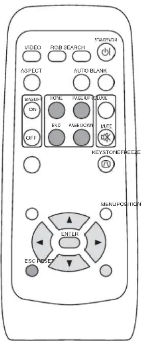
You can use the remote control as a simplified mouse or keyboard.

CAUTION Caution: Mistaken use of the mouse/keyboard control could damage your equipment.
- Only connect to a PC.
- Before connecting, read the manuals of the device you will connect.
- Do not unplug the connector cables while the computer is operating.
PS/2, ADB, Serial Mouse Control
- Turn off the projector and PC power, and connect the projector's CONTROL terminal to the computer via the mouse cable.
- If a USB cable is connected, disconnect it. If a USB cable is connected, the USB control function is given priority, and mouse control from the CONTROL terminal will not function.
- Turn on the projector power, then the computer. The functions in the table below can be controlled. If you have difficulty with control, restart the computer (either from the software or by pressing the restart button).
| Available Functions Remote Control Operation | |
| Move Pointer | Use ▶ ▶ ▶ ▼ buttons |
| Left click with mouse Press ENTER button | |
| Right click with mouse Press RESET button | |
USB Mouse/Keyboard Control
- Connect the projector's USB terminal to the computer using a USB cable. The functions in the table below can be controlled.
| Available Functions Remote Control Operation | |
| Move Pointer | Use ▲ ▶ ▲ ▼ buttons |
| Left click with mouse Press ENTER button | |
| Right click with mouse Press RESET button | |
| Press keyboard's HOME key Press HOME button | |
| Press keyboard's END key Press END button | |
| Press keyboard's PAGE UP key Press PAGE UP button | |
| Press keyboard's PAGE DOWN key | Press PAGE DOWN button |
| Press keyboard's ESC key | Press ESC button |
NOTES
- It may not be possible to control notebook PCs, and other computers with built-in pointing devices (e.g. track balls), using this remote control. In this case, before connecting go into BIOS (system setup) and select external mouse, and disable the pointing devices. In addition, the mouse may not function if the computer does not have the needed utility program. See your computer's hardware manual for details.
- The USB control can be used with Windows 95 OSR 2.1 or higher. It may not be possible to use the remote control, depending on the computer's configurations and mouse drivers.
- The USB control can only be used for the functions listed above. You cannot do things like press two buttons at once (for instance, pressing two buttons at the same time to move the mouse pointer diagonally).
- This function is not available while the lamp is warming up (the POWER indicator flashes green), while adjusting the volume and display, correcting for trapezoidal distortion, zooming in on the screen, using the BLANK function, or displaying the menu screen.


HIGH VOLTAGE
HIGH TEMPERATURE
HIGH PRESSURE
Before replacing the lamp, check the serial number of your separately sold replacement lamp bulb (78-6969-9599-8 for MP7650 / 78-6969-9635-0 for MP7750), then contact your local dealer.
Before replacing the lamp, turn off the power, and unplug the power cord, then wait at least 45 minutes, in order to ensure that the lamp is properly cooled. Removing the lamp bulb while it is still hot could cause burns, or cause the lamp bulb to burst.

WARNING
The LCD projector uses a glass lamp bulb. It is a mercury lamp with high internal pressure. High-pressure mercury lamps can break with a loud bang, or burn out, if jolted or scratched, or through wear over time. Each lamp has a different lifetime, and some may burst or burn out soon after you start using them. In addition, when the bulb bursts, it is possible for shards of glass to fly into the lamp housing, and for gas containing mercury to escape from the projector's vent holes.
- Handle with care: jolting or scratching could cause the lamp bulb to burst during use.
- If the replace lamp indicator (see "Related Messages" 35 and "Regarding the indicator Lamps" 36 comes on, replace the lamp as soon as possible. Using the lamp for long periods of time, or past the replacement date, could cause it to burst. Do not use old (used) lamps; this is a cause of breakage.
- If the lamp breaks soon after the first time it is used, it is possible that there are electrical problems elsewhere besides the lamp. If this happens, contact your local dealer.
- If the lamp should break (it will make a loud bang when it does), ventilate the room well, and make sure not to breathe the gas that comes out of the projector vents, or get it in your eyes or mouth.
- If the lamp should break (it will make a loud bang when it does), unplug the power cord from the outlet, and make sure to request a replacement lamp from your local dealer. Note that shards of glass could damage the projector's internals, or cause injury during handling, so please do not try to clean the projector or replace the lamp yourself.
- Obey local ordinances when disposing of used lamps. In most cases, it is possible to dispose of used bulbs in the same manner as used glass bottles, but in some cases, bulbs are sorted separately.
- Do not use the projector with the lamp cover removed.
THE LAMP (continued)
Replacing the lamp
All projector lamps will wear out eventually. If used for long periods of time, the image could become darkened, and the color contrast could be impacted as well. We recommend that you replace your lamps early. If the LAMP indicator turns red, or a message prompts you to replace the lamp when you power up the projector, the lamp needs to be replaced. (See "Related Messages" 35 and "Regarding the Indicator Lamps" 36 for details.)
1 Turn off the projector, and unplug the power cord. Allow the lamp bulb to cool for at least 45 minutes, and prepare a new lamp.
2 After making sure that the projector has cooled adequately, slowly flip over the projector, so that the bottom is facing up
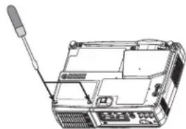
3 Unscrew the 2 screws, and remove the lamp cover
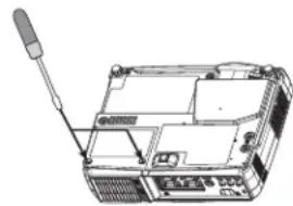
natural_image
Line drawing of a device with a screwdriver inserted, showing internal components and no text or symbols4 Unscrew the 1 screw, and slowly pull out the lamp by the handle - Be careful not to touch the inside of the lamp case.
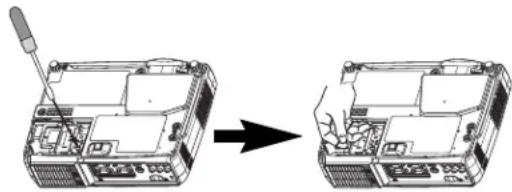
natural_image
Diagram showing a device being processed from a tool, with no visible text or symbols5 Insert the new lamp, and tighten the 1 screw firmly to lock it in place
- Also steadily push the opposite side of the screwed side of the lamp into the unit.
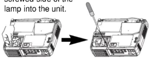
6 Replace the lamp cover, and tighten the 2 screws firmly to lock it in place
natural_image
Line drawing of a device with a screwdriver inserted, showing internal components and no text or symbols7 Slowly turn the projector so that the top is facing up
8 Turn on the projector power, and using the menu, reset the lamp timer
- To reset the lamp timer, from the OPTION menu, select LAMP TIME.
ATTENTION • Make sure that the screws are screwed in firmly. Loose screws could result in damage or injury.
- Do not use with lamp cover removed.
- Do not reset the lamp timer without replacing the lamp. Reset the lamp timer always when replacing the lamp. The message functions will not operate properly if the lamp timer is not reset correctly.
- When the lamp has been replaced after the message of "CHANGE THE LAMP ...THE POWER WILL TURN OFF AFTER 0 hr." is displayed, or the LAMP indicator is red, complete the following operation within 10 minutes of switching power ON.
NOTE • The LAMP indicator is also red when the lamp unit reaches high temperature.
Before replacing the lamp, switch power OFF, wait approximately 20 minutes, and switch power ON again. If the LAMP indicator is still red, replace the lamp.
THE AIR FILTER
Caring for the air filter
The air filter should be cleaned about every 100 hours. If the LAMP indicator and TEMP indicator blink red simultaneously, or a message prompts you to clean the air filter when you turn on the unit, the filter needs to be cleaned. (See "Related Messages" 35 and "Regarding the Indicator Lamps" 36 for details.)
1 Turn off the projector, and unplug the power cord
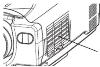
2 Apply a vacuum cleaner to the top of the air filter cover to clean the air filter
natural_image
Technical line drawing of a vehicle front panel with ventilation grilles and a mesh grille (no text or symbols)Air Filter Cover
3 Turn on the projector, and use the menu to reset the filter timer
- To reset the air filter timer, from the OPTION menu, select FILTER TIME.
THE AIR FILTER (continued)
Replacing the air filter
If the soiling will not come off the air filter, or it becomes damaged, then it needs to be replaced. Please contact your local dealer, after confirming the serial number of your separately sold replacement air filter (78-8118-9055-3).
1 Turn off the projector, and unplug the power cord. Prepare a new air filter (one specified for your projector)
2 Remove the air filter cover and air filter
3 Insert the new filter, and replace the filter cover
4 Turn on the projector power, and using the menu, reset the filter timer
- To reset the lamp timer, from the OPTION menu, select FILTER TIME.
ATTENTION • Make sure to turn off the power and unplug the power cord before caring for the unit. Please carefully read "Safety Instructions", in order to care for your projector correctly.
- Do not use with air filter cover removed.
- If the air filter becomes clogged by dust or the like, internal temperature rises and could cause malfunction. The power is automatically turned off in order to prevent the unit from overheating internally.
OTHER CARE
Caring for the inside of the projector :
In order to ensure the safe use of your projector, please have it cleaned and inspected by your local dealer about once every 2 years. Never try to care for the inside of the unit yourself. Doing so is dangerous.
Caring for the lens :
Lightly wipe the lens with a commercially available lens-cleaning wipe. Do not touch the lens directly with your hand.
Caring for the cabinet and remote control transmitter :
Wipe lightly with gauze or a soft cloth. If soiling is severe, dip a soft cloth in water or a neutral cleanser diluted in water, and wipe lightly after wringing well. Then, wipe lightly with a soft, dry cloth.
ATTENTION • Make sure to turn off the power and unplug the power cord before caring for the unit. Please carefully read "Safety Instructions" in this manual, in order to care for your projector correctly.
- Do not use cleaners or chemicals other than those listed above, including benzene and paint thinner.
- Do not use aerosols or sprays.
- Do not polish or wipe with hard objects.
WHAT TO DO WHEN YOU THINK A MACHINE DEFECT HAS OCCURRED
Related Messages
When the unit's power is ON, messages such as those shown below may be displayed. When any such message is displayed on the screen, please respond as described below.
| Message Description | |
| CHANGE THE LAMP AFTER REPLACING LAMP, RESET THE LAMP TIMER. (Note 1) | Lamp usage time is approaching 2,000 hours. (Note 2)Preparation of a new lamp, and an early lamp change, is recommended. After you have changed the lamp, please be sure to reset the lamp timer. |
| CHANGE THE LAMP AFTER REPLACING LAMP, RESET THE LAMP TIMER. THE POWER WILL TURN OFF AFTER * * hr. (Note 1) | Lamp usage time is approaching 2,000 hours. A lamp change within * * hours is recommended. (Note 2)When lamp usage reaches 2,000 hours, the power will automatically be turned OFF. Please change the lamp by referring to “THE LAMP” in Vol.1 (Basic). After you have changed the lamp, please be sure to reset the lamp timer. |
| CHANGE THE LAMP AFTER REPLACING LAMP, RESET THE LAMP TIMER. THE POWER WILL TURN OFF AFTER 0 hr. | As lamp use has reached 2,000 hours, the power will soon be automatically turned OFF. (Note 2)Please immediately turn the power OFF, and follow the instructions in the “THE LAMP” section of the separate booklet, Vol.1 (Basic).After you have changed the lamp, please be sure to reset the lamp timer. |
| CLEAN THE AIR FILTER AFTER CLEANING AIR FILTER, RESET THE FILTER TIMER. | A note of precaution when cleaning the air filter.After cleaning the filter, operate FILTER TIME of the OPTION Menu, and perform reset of the filter timer. |
| NO INPUT IS DETECTED ON * * * | There is no input signal.Please confirm the signal input connection, and the status of the signal source. |
| SYNC IS OUT OF RANGE ON ***fH V*****kHz Hz ***** | The horizontal or vertical wavelength of the inputted signal is outside of the response parameters of this unit. Please confirm the specs for this unit or the signal source specs. |
| CHECK THE AIR FLOW | The internal portion temperature is rising. Please turn the power OFF, and allow the unit to cool down for approximately 20 minutes. After having confirmed the following items, then please resent the power to ON.Is there blockage of the air passage aperture?Is the air filter dirty?Does the peripheral temperature exceed 35°C? |
NOTES
Note 1: Although this message will be automatically disappeared after around 3 minutes, it will be reappeared every time the power is turned ON.
Note 2: Lamps have a finite product life. Lamps are characterized by the fact that, after long hours of usage, a lamp will no longer light up, or the lamp will break or burst, etc. This unit is equipped with an automatic shut-down function, such that the power will automatically be turned OFF when lamp usage time has reached 2,000 hours. Please be aware, however, that among lamp types, there are major differences in product lifetimes; a lamp may thus fail to light even prior to the functioning of the automatic shut-down function of this unit.
Regarding the Indicator Lamps
Lighting and flashing of the POWER indicator, the LAMP indicator, and the TEMP indicator have the meanings as described in the Table below.
Please respond in accordance with the instructions within the Table.
| POWER indicator | LAMP indicator | TEMP indicator | Description |
| The orange lamp is lighted | Turned OFF (Not lighted) | Turned OFF (Not lighted) | The STANDBY mode is set |
| Flashing of the green lamp | Turned OFF | Turned OFF | The unit is warming up. Please wait. |
| The green lamp is lighted | Turned OFF | Turned OFF | The unit is in an ON state. Ordinary operations may be performed. |
| Flashing of the orange lamp | Turned OFF | Turned OFF | The unit is cooling down. Please wait. |
| Blinking of the red lamp | - | - | The unit is cooling down. Please wait.A certain error has been detected. Wait until the POWER indicator lamp has finished flashing, and then perform the proper response measure using the item descriptions below as reference. |
| The red lamp is lighted, or blinks | The red lamp is lighted | Turned OFF | The lamp does not light.There is a possibility that the interior portion has become heated. Turn the power OFF and wait approximately 20 minutes. After the main unit has cooled down, please confirm whether or not there is blockage of the air passage aperture, whether or not the filter is dirty, and/or whether or not the peripheral temperature exceeds 35°C, etc. After performing any needed maintenance, turn the power ON again; if the same display is displayed, then please change the lamp. |
| The red lamp is lighted, or blinks | Blinking of the red lamp | Turned OFF | Either there is no lamp and/or lamp cover, or either of these has not been properly fixed (attached). Turn the power OFF and wait approximately 45 minutes. After the main unit has sufficiently cooled down, please make confirmation of the attachment state of the lamp and lamp cover. After performing any needed maintenance, turn the power ON again; if the same display is displayed, then please contact a sales store or a service company. |
| The red lamp is lighted, or blinks | Turned OFF | Blinking of the red lamp | The cooling fan is not operating. Turn the power OFF and wait approximately 20 minutes. After the main unit has cooled down, please make confirmation that no foreign matter has become caught in the fan, etc. After performing any needed maintenance, turn the power ON again; if the same display is displayed, then please contact a sales store or a service company. |
| The red lamp is lighted, or blinks | Turned OFF | The red lamp is lighted | There is a possibility that the interior portion has become heated. Turn the power OFF and wait approximately 20 minutes. After the main unit has cooled down, please confirm whether or not there is blockage of the air passage aperture, whether or not the filter is dirty, and/or whether or not the peripheral temperature exceeds 35°C, etc. After performing any needed maintenance, turn the power ON again; if the same display is displayed, then please contact a sales store or a service company. |
| The green lamp is lighted | Alternative blinking with the red lamp | There is a possibility that the interior portion has become overcooled. Please use the unit within the usage temperature parameters (0°C to 35°C). After performing any needed maintenance, turn the power ON again; if the same display is displayed, then please contact a sales store or a service company. | |
| The green lamp is lighted | Simultaneous blinking with the red lamp | This is a notification that it is time to clean the filter.After cleaning the filter, operate the FILTER TIME portion of the OPTION Menu, and perform reset of the FILTER TIME. | |
NOTE
When the interior portion has become overheated, for safety purposes, the power source is automatically turned OFF, and the indicator lamps may also be turned OFF. Press the “○” (power OFF) side of the main power switch, and wait for approximately 20 minutes. Please then use the unit only after having first confirmed that the unit has sufficiently cooled down.
WHAT TO DO WHEN YOU THINK A MACHINE DEFECT HAS OCCURRED (continued)
Phenomena That May Easily Be Mistaken for Machine Defects
Before requesting repair, check in accordance with the following chart.
If the situation cannot be corrected, then contact your dealer.
| Phenomenon | Cases not involving a machine defect | Items to be confirmed | Reference Page(s) |
| Power does not come ON | The main power source is not ON. | Turn on the main power. | 3, 14 |
| The electrical power cord is not plugged in. Correctly connect the power cord. | |||
| The main power source has been interrupted during operation, such as by a power outage (blackout), etc. | Be sure to press the “O” (power OFF) side of the main power switch, and leave this OFF for approximately 20 minutes. After the unit has sufficiently cooled down, turn ON the power source. | 14 | |
| No sound or pictures are outputted | The input changeover settings are mismatched. | Select the input signal, and correct the settings. | 15 |
| No signal is being inputted. | Correctly connect the connection cord. | 10, 11 | |
| Pictures are displayed, but no sounds are heard | The electrical wiring to this unit is not correctly connected. | Correctly connect the connection cord. | 10, 11 |
| The volume setting has been set at (or adjusted to) an extremely low level. | Adjust the VOLUME setting to a higher level. | 17 | |
| The MUTE mode is the current setting. | Press the MUTE button to release (change) the MUTE mode setting. | 17 | |
| Sounds are heard, but no pictures are displayed | The electrical wiring to this unit is not correctly connected. | Correctly connect the connection cord. | 10, 11 |
| The brightness setting has been set at (or adjusted to) an extremely low level. | Adjust the BRIGHT setting to a brighter level. | 24 | |
| The lens cap has not been removed. | Remove the lens cap. | 14 | |
| Colors have a faded-out appearance Color tone is poor | Color depth setting or color tone setting | Perform picture adjustments by changing the COLOR BAL R, the COLOR BAL B, and/or the TINT settings, etc. | 25 |
| Pictures appear dark | The brightness setting and/or contrast setting has not been properly adjusted. | Perform picture adjustments by changing the BRIGHT and/or CONTRAST settings, etc. | 24 |
| The WHISPER mode is the current setting. | Change (by releasing) from the WHISPER mode. | 28 | |
| Lamp is approaching the end of its product lifetime. | Exchange the old lamp with a new lamp. | 30, 31 | |
| Pictures appear blurry | Either the FOCUS setting or the H PHASE is not properly adjusted. | Adjust the FOCUS and H PHASE settings. | 15, 25 |
NOTE
Although bright spots or dark spots may appear on the screen, this is a unique characteristic of liquid crystal displays, and such do not constitute or imply a machine defect.
SPECIFICATIONS
NOTE • This specifications are subject to change without notice.
| Item Specification | ||
| Product name Liquid crystal projector | ||
| Liquid crystal panel | Panel size 1.8 cm (0.7 type) | |
| Drive system TFT active matrix | ||
| Pixels | MP7650 480,000 pixels (800 horizontal x600 vertical)MP7750 : 786,432 pixels (1024 horizontal x 768 vertical) | |
| Lens Zoom lens F=1.7 ~ 1.9 f=21.7 ~ 26.1 mm | ||
| Lamp 150 W UHB | ||
| Speaker 1.0W | ||
| Power supply AC100 ~ 120V, 2.7A / AC220 ~ 240V, 1.3A | ||
| Power consumption 240W | ||
| Temperature range 0 ~ 35°C (Operating) | ||
| Size 295 (W) x 87.5 (H) x237 (D) mm | ||
| Weight (mass) 2.7 kg | ||
| Terminal | RGB TerminalAUDIO TerminalRGB IN(1, 2)......2AUDIO IN(R, L)......1VIDEO TerminalOUT TerminalVIDEO IN......1RGB OUT......1S-VIDEO IN......1CONTROL TerminalCOMPONENT VIDEOCONTROL......1(Y, CB/PB,CR/PR)......1USB......1 | |
Dimension Diagram
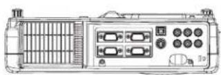
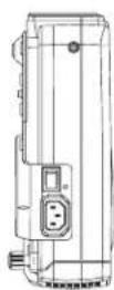
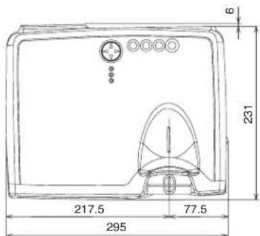
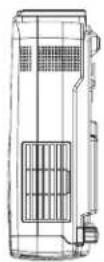
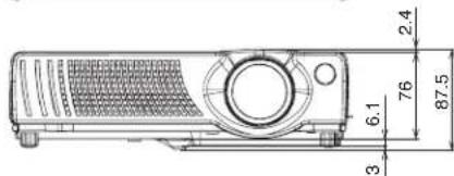
Unit : mm
ACCESSORIES
Accessories ...... Part Number
UHB Lamp, 150W (for MP7650) 78-6969-9599-8
UHB Lamp, 150W (for MP7750) 78-6969-9635-0
Air Filter Assy 78-8118-9055-3
Power Cord (US) 78-8118-8102-4
Power Cord (UK) 78-8118-8101-6
Power Cord (Europe) 78-8118-8103-2
VGA Cable 78-8118-8708-8
RCA Video/Audio Cable 78-8118-3234-0
RCA Component Cable w/core 78-8118-9056-1
USB cable 78-8118-9057-9
Remote Control 78-8118-9054-6
Soft Carrying Case 78-6969-9203-7
Not Included with Basic Packet .... Part Number
Ceiling Mount 78-6969-9611-1
Adjustable Height Suspension 78-6969-9564-2
Shipping Case 78-6969-9035-3
S-Video Cable 78-8118-3238-1
Mouse Cable (PS/2) 78-8118-8105-7
Mouse Cable (Serial) 78-8118-8107-3
Mouse Cable (ADB) 78-8118-8106-5
RS-232C Cable 78-8118-3312-4
Mac Adapter 78-8118-3308-2
How to Order
Please order these parts through your dealer, or contact 3M Customer Service at the following number:
In U.S. or Canada : 1-800-328-1371
In other locations, contact your local 3M sales office.
MP7650/MP7750 Multimedia Projector
Operator's Guide - Technical
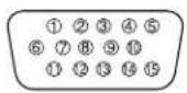
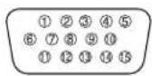
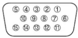
SIGNAL CONNECTOR PIN ASSIGNMENT
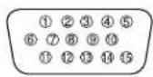
RGB IN [1]/[2]
RGB OUT
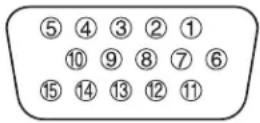
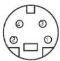
S-VIDEO
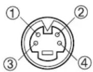
D-sub 15-pin Shrink Mini Din 4-pin
| Pin No | Signal Pin No Signal | ||
| 1 Video input Red 9 - | |||
| 2 | Video input Green | 10 | Ground |
| 3 | Video input Blue | 11 | - |
| 4 | - | 12RGB OUT : | RGB IN [1]: SDA (DDC) |
| 5 Ground | B IN [2]: - | ||
| 6 Ground Red | B OUT : - | ||
| 7 Ground Green | 13 | H. sync./ Composite sync. | |
| 8 | Ground Blue | 14 | Vertical sync |
| 15 | RGB IN [1]: SCL (DDC) | ||
| RGB IN [2]: - | |||
| RGB OUT : - | |||
| Mini Din 4-pin | |
| Pin No | Signal |
| 1 | Color:0.286Vp-p (NTSC, burst signal),75Ω terminator0.3Vp-p (PAL/SECAM, burst signal),75Ω terminator |
| 2 | Brightness:1.0Vp-p, 75Ω terminator |
| 3 Ground | |
| 4 Ground | |
| signal Terminal Specification | |||
| RGB signal input | RGB IN 1(2、) | Video: Analog 0.7Vp-p, 75Ω terminator (positive)H/V. sync.: TTL level (positive/negative)Composite sync.: TTL levelD-sub 15-pin shrink jack | |
| Video signal input | VIDEO IN 1.0Vp-p, 75Ω terminator, RCA jack | ||
| S-VIDEO IN | Brightness signal: 1.0Vp-p, 75Ω terminatorColor signal: 0.286Vp-p (NTSC, burst signal),75Ω terminator0.300Vp-p (PAL/SECAM, burst signal),75Ω terminatorMini DIN 4-pin jack | ||
| COMPONENT VIDEO | Y 1.0 | Vp-p, 75 Ω Terminator (Positive) | |
| CB/PB | 0.7 Vp-p, 75 Ω Terminator (Positive) | ||
| CR/PR | 0.7 Vp-p, 75 Ω Terminator (Positive) | ||
| Audio signal input | AUDIO IN R(L、) | 200mVrms, 50 kΩ (max. 3.0Vp-p)RCA jack | |
| Signal output | RGB OUT | Video: Analog 0.7Vp-p, 75Ω output impedance (positive)H/V. sync.: TTL level (positive/negative)Composite sync.: TTL levelD-sub 15-pin shrink jack | |
EXAMPLE OF COMPUTER SIGNAL
| ResolutionH × V | fH (kHz) fV | (Hz) Rating | Signal mode | Display mode | ||
| MP7650MP | 7750 | |||||
| 720 × 400 | 37.9 85.0 | VESA TEXT | Zoom in Zoom in | |||
| 640 × 480 | 31.5 59.9 | VESA VGA | (60Hz) Zoom in Zoom in | |||
| 640 × 480 | 35.0 66.7 | Mac13"mode | Zoom in Zoom in | |||
| 640 × 480 | 37.9 72.8 | VESA VGA | (72Hz) Zoom in Zoom in | |||
| 640 × 480 | 37.5 75.0 | VESA VGA | (75Hz) Zoom in Zoom in | |||
| 640 × 480 | 43.3 85.0 | VESA VGA | (85Hz) Zoom in Zoom in | |||
| 800 × 600 | 35.2 56.3 | VESA SVGA | (56Hz) Zoom in | |||
| 800 × 600 | 37.9 60.3 | VESA SVGA | (60Hz) Zoom in | |||
| 800 × 600 | 48.1 72.2 | VESA SVGA | (72Hz) Zoom in | |||
| 800 × 600 | 46.9 75.0 | VESA SVGA | (75Hz) Zoom in | |||
| 800 × 600 | 53.7 85.1 | VESA SVGA | (85Hz) Zoom in | |||
| 832 × 624 | 49.7 74.5 | Mac16"mode | Zoom out Zoom in | |||
| 1024 × 768 | 48.4 60.0 | VESA XGA | (60Hz) Zoom out | |||
| 1024 × 768 | 56.5 70.1 | VESA XGA | (70Hz) Zoom out | |||
| 1024 × 768 | 60.0 75.0 | VESA XGA | (75Hz) Zoom out | |||
| 1024 × 768 | 68.7 85.0 | VESA XGA | (85Hz) Zoom out | |||
| 1152 × 864 | 67.5 | 75.0 | VESA | SXGA (75Hz) | Zoom out | Zoom out |
| 1280 × 960 | 60.0 | 60.0 | VESA | SXGA (60Hz) | Zoom out | Zoom out |
| 1280 × 1024 | 64.0 | 60.0 | VESA | SXGA (60Hz) | Zoom out | Zoom out |
| 1280 × 1024 | 80.0 | 75.0 | VESA | SXGA (75Hz) | Zoom out | Zoom out |
| 1280 × 1024 | 91.2 | 85.0 | VESA | SXGA (85Hz) | Zoom out | Zoom out |
| 1600 × 1200 | 75.0 | 60.0 | VESA | UXGA (60Hz) | Zoom out | Zoom out |
NOTE
- Some computers may have multiple display screen modes. Use of some nodes will not be possible with this projector.
- Be sure to check jack type, signal level, timing and resolution before connecting this projector to a computer.
- Depending on the input signal, full-size display may not be possible in some cases. Refer to the number of display pixels above.
- This projector will display up to UXGA (1600X1200) resolution signals but the image will be rescaled to the native resolution of the projector. Best display performance is achieved when the signal input resolution is the same as the native resolution of the projector.
- The image may not be displayed correctly when the input sync. signal is “Composite Sync.” or “Sync. on G”.
INITIAL SET SIGNALS
The following signals are used for the initial settings.
The signal timing of some computer models may be different. In such case, refer to adjust the V.POSIT and H.POSIT of the menu.
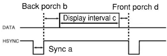
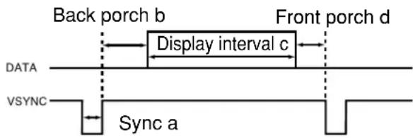
| Computer / Signal | Horizontal signal timing (μs) | |||
| a b d | ||||
| TEXT 2.0 3.0 | 20.3 | 1.0 | ||
| VGA (60Hz) 3.8 | 1.9 | 25.4 | 0.6 | |
| Mac 13"mode 2.1 | 3.2 | 21.2 | 2.1 | |
| VGA (72Hz) 1.3 | 3.8 | 20.3 | 1.0 | |
| VGA (75Hz) 2.0 | 3.8 | 20.3 | 0.5 | |
| VGA (85Hz) 1.6 | 2.2 | 17.8 | 1.6 | |
| SVGA (56Hz) 2.0 | 3.6 | 22.2 | 0.7 | |
| SVGA (60Hz) 3.2 | 2.2 | 20.0 | 1.0 | |
| SVGA (72Hz) 2.4 | 1.3 | 16.0 | 1.1 | |
| SVGA (75Hz) 1.6 | 3.2 | 16.2 | 0.3 | |
| SVGA (85Hz) 1.1 | 2.7 | 14.2 | 0.6 | |
| Mac 16"mode 1.1 | 3.9 | 14.5 | 0.6 | |
| XGA (60Hz) 2.1 | 2.5 | 15.8 | 0.4 | |
| XGA (70Hz) 1.8 | 1.9 | 13.7 | 0.3 | |
| XGA (75Hz) 1.2 | 2.2 | 13.0 | 0.2 | |
| XGA (85Hz) 1.0 | 2.2 | 10.8 | 0.5 | |
| 1152×864 (75Hz) | 1.2 | 2.4 | 10.7 | 0.6 |
| 1280×960 (60Hz) | 1.0 | 2.9 | 11.9 | 0.9 |
| 1280×1024 (60Hz) | 1.0 | 2.3 | 11.9 | 0.4 |
| 1280×1024 (75Hz) | 1.1 | 1.8 | 9.5 | 0.2 |
| 1280×1024 (85Hz) | 1.0 | 1.4 | 8.1 | 0.4 |
| 1600×1200 (60Hz) | 1.2 | 1.9 | 9.9 | 0.4 |
| Computer / Signal | Vertical signal timimg (lines) | |||
| a b c d | ||||
| TEXT 3 42 | 400 1 | |||
| VGA (60Hz) 2 | 33 480 1 | 0 | ||
| Mac 13"mode 3 | 39 480 3 | |||
| VGA (72Hz) 3 | 28 480 9 | |||
| VGA (75Hz) 3 | 16 480 1 | |||
| VGA (85Hz) 3 | 25 480 1 | |||
| SVGA (56Hz) | 2 22 | 600 1 | ||
| SVGA (60Hz) | 4 23 | 600 1 | ||
| SVGA (72Hz) | 6 23 | 600 37 | ||
| SVGA (75Hz) | 3 21 | 600 1 | ||
| SVGA (85Hz) | 3 27 | 600 1 | ||
| Mac 16"mode 3 | 39 624 1 | |||
| XGA (60Hz) 6 | 29 768 3 | |||
| XGA (70Hz) 6 | 29 768 3 | |||
| XGA (75Hz) 3 | 28 768 1 | |||
| XGA (85Hz) 3 | 36 768 1 | |||
| 1152×864 (75Hz) | 3 32 | 864 1 | ||
| 1280×960 (60Hz) | 3 36 | 960 1 | ||
| 1280×1024 (60Hz) | 3 38 | 1024 1 | ||
| 1280×1024 (75Hz) | 3 37 | 1024 2 | ||
| 1280×1024 (85Hz) | 3 44 | 1024 1 | ||
| 1600×1200 (60Hz) | 3 46 | 1200 1 | ||
CONNECTION TO THE MOUSE CONTROL
ADB Mouse
CONTROL Terminal
D-sub 15-pin shrink jack
Projector
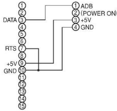
Computer
Mouse jack
Mini DIN 4-pin
Serial Mouse
CONTROL Terminal
D-sub 15-pin shrink jack
Projector
Computer
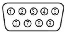
Mouse jack D-sub 9-pin
USB Mouse
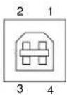
USB jack (B type)
Projector
Computer
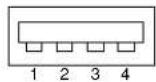
USB jack (A type)
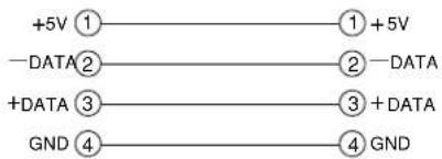
USB cable
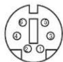
PS/2 Mouse
CONTROL Terminal
D-sub 15-pin shrink jack
Projector
Computer
Mouse jack
Mini DIN 6-pin
© 3M 2002. All Rights Reserved.
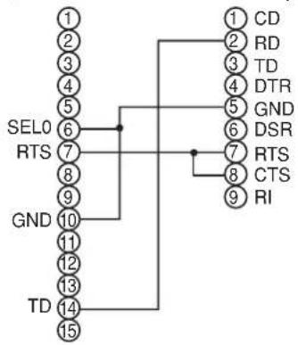
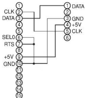
RS-232C COMMUNICATION
(1) Turn off the projector and computer power supplies and connect with the RS-232C cable.
(2) Turn on the computer power supply and after the computer has started up, turn on the projector power supply.
Control jack
D-sub 15-pin shrink jack
Projector Computer
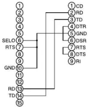
flowchart
graph TD
    A["1"] --> B["SELO"]
    C["2"] --> B
    D["3"] --> B
    E["4"] --> B
    F["5"] --> B
    G["6"] --> B
    H["7"] --> B
    I["8"] --> B
    J["9"] --> B
    K["GND"] --> B
    L["10"] --> B
    M["11"] --> B
    N["12"] --> B
    O["13"] --> P["RD"]
    Q["14"] --> P
    R["15"] --> P
    S["1"] --> T["CD"]
    U["2"] --> T
    V["3"] --> W["RD"]
    X["4"] --> Y["TD"]
    Z["5"] --> AA["DTR"]
    AB["6"] --> AC["GND"]
    AD["7"] --> AE["DSR"]
    AF["8"] --> AG["RTS"]
    AH["9"] --> AI["DTS"]
    AJ["10"] --> AK["RI"]
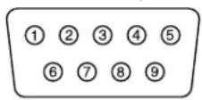
RS-232C jack
D-sub 9-pin
Communications setting
19200bps, 8N1
1 Protocol
Consist of header (7 bytes) + command data (6 bytes).
2 Header
BE + EF + 03 + 06 + 00 + CRC_low + CRC_high
CRC_low : Lower byte of CRC flag for command data.
CRC_high : Upper byte of CRC flag for command data.
3 Command data
Command data chart
| byte_0 byte_1 byte_2 byte_3 byte_4 byte_5 | |||||
| Action Type Setting code | |||||
| low high | low high low high | ||||
Action (byte_0 - 1)
| Action Classification Content | |
| 1 SET Change setting to desired value. | |
| 2 GET Read projector internal setup value. | |
| 4 INCREMENT Increment setup value by 1. | |
| 5 DECREMENT Decrement setup value by 1. | |
| 6 EXECUTE Run a command. |
RS-232C COMMUNICATION (continued)
Requesting projector status (Get command)
(1) Send the request code Header + Command data ('02H' + '00H' + type (2 bytes) + '00H' + '00H') from the computer to the projector.
(2) The projector returns the response code '1DH'+ data (2 bytes) to the computer.
Changing the projector settings (Set command)
(1) Send the setting code Header + Command data ('01H' + '00H' + type (2 bytes) + setting code (2 bytes)) from the computer to the projector.
(2) The projector changes the setting based on the above setting code.
(3) The projector returns the response code '06H' to the computer.
Using the projector default settings (Reset Command)
(1) The computer sends the default setting code Header + Command data ('06H' + '00H' + type (2 bytes) + '00H' + '00H') to the projector.
(2) The projector changes the specified setting to the default value.
(3) The projector returns the response code '06H' to the computer.
Increasing the projector setting value (Increment command)
(1) The computer sends the increment code Header + Command data ('04H' + '00H' + type (2 bytes) + '00H' + '00H') to the projector.
(2) The projector in creases the setting value on the above setting code.
(3) The projector returns the response code '06H' to the computer.
Decreasing the projector setting value (Decrement command)
(1) The computer sends the decrement code Header + Command data ('05H' + '00H' + type (2 bytes) + '00H' + '00H') to the projector.
(2) The projector decreases the setting value on the above setting code.
(3) The projector returns the response code '06H' to the computer.
When a command sent by the projector cannot be understood by the computer
When the command sent by the projector cannot be understood, the error command '15H' is returned by the computer. Some times, the projector ignores RS-232C commands during other works. If the error command '15H' is returned, please send the same command again.
When data sent by the projector cannot be practice
When the command sent by the projector cannot be practiced, the error code '1cH' + 'xxxxH' is returned.
When the data length is greater than indicated by the data length code, the projector will ignore the excess data code.
Conversely, when the data length is shorter than indicated by the data length code, an error code will be returned to the projector.
NOTE
- Operation cannot be guaranteed when the projector receives an I command or data.
- Provide an interval of at least 40ms between the response code and any other code.
- The projector outputs test data when the power supply is switched ON, and when the lamp is lit. Ignore this data.
- Commands are not accepted during warm-up.
Command data chart
| Names Operation type Header | Command data | |||||||||
| CRC Action Type Setting code | ||||||||||
| Blank Color | Set | Blue BE EF 03 06 00 CB D3 01 00 00 30 03 00 | ||||||||
| White BE EF 03 06 00 6B D0 01 00 00 30 05 00 | ||||||||||
| Black BE EF 03 06 00 9B D0 01 00 00 30 06 00 | ||||||||||
| MyScreen BE EF 03 06 00 FB CA 01 00 00 30 20 00 | ||||||||||
| ORIGINAL BE EF 03 06 00 FB E2 01 00 00 30 40 00 | ||||||||||
| Get | BE EF 03 06 00 | 08 D3 | 02 00 | 00 30 | 00 00 | |||||
| Mirror | Set | Normal | BE EF 03 06 00 | C7 D2 | 01 00 | 01 30 | 00 00 | |||
| H Inverse | BE EF 03 06 00 | 57 D3 | 01 00 | 01 30 | 01 00 | |||||
| V Inverse | BE EF 03 06 00 A7 D3 | 01 00 01 | 30 02 00 | |||||||
| H&V Inverse | BE EF 03 06 00 | 37 D2 | 01 00 | 01 30 | 03 00 | |||||
| Get | BE EF 03 06 00 | F4 D2 | 02 00 | 01 30 | 00 00 | |||||
| Freeze | Set | Normal | BE EF 03 06 00 | 83 D2 | 01 00 | 02 30 | 00 00 | |||
| Freeze | BE EF 03 06 00 | 13 D3 | 01 00 | 02 30 | 01 00 | |||||
| Get | BE EF 03 06 00 | B0 D2 | 02 00 | 02 30 | 00 00 | |||||
| Startup | Set | ORIGINAL BE EF 03 06 00 0B D2 01 00 04 30 00 00 | ||||||||
| OFF BE EF 03 06 00 9B D3 01 00 04 30 01 00 | ||||||||||
| MyScreen BE EF 03 06 00 CB CB 01 00 04 30 20 00 | ||||||||||
| Get | BE EF 03 06 00 | 38 D2 | 02 00 | 04 30 | 00 00 | |||||
| Language | Set | English | BE EF 03 06 00 | F7 D3 | 01 00 | 05 30 | 00 00 | |||
| Français | BE EF 03 06 00 | 67 D2 | 01 00 | 05 30 | 01 00 | |||||
| Deutsch | BE EF 03 06 00 | 97 D2 | 01 00 | 05 30 | 02 00 | |||||
| Español | BE EF 03 06 00 | 07 D3 | 01 00 | 05 30 | 03 00 | |||||
| Italiano | BE EF 03 06 00 | 37 D1 | 01 00 | 05 30 | 04 00 | |||||
| Norsk | BE EF 03 06 00 A7 D0 | 01 00 05 | 30 05 00 | |||||||
| Nederlands | BE EF 03 06 00 | 57 D0 | 01 00 | 05 30 | 06 00 | |||||
| Português | BE EF 03 06 00 | C7 D1 | 01 00 | 05 30 | 07 00 | |||||
| 日本語 | BE EF 03 06 00 | 37 D4 | 01 00 | 05 30 | 08 00 | |||||
| 中文 | BE EF 03 06 00 A7 D5 | 01 00 05 | 30 09 00 | |||||||
| 한글 | BE EF 03 06 00 | 57 D5 | 01 00 | 05 30 | 0A 00 | |||||
| Get | BE EF 03 06 00 | C4 D3 | 02 00 | 05 30 | 00 00 | |||||
| Magnify | Get | BE EF 03 06 00 | 7C D2 | 02 00 | 07 30 | 00 00 | ||||
| Increment | BE EF 03 06 00 | 1A D2 | 04 00 | 07 30 | 00 00 | |||||
| Decrement | BE EF 03 06 00 | CB D3 | 05 00 | 07 30 | 00 00 | |||||
| Auto off | Get | BE EF 03 06 00 | 08 86 | 02 00 | 10 31 | 00 00 | ||||
| Increment | BE EF 03 06 00 | 6E 86 | 04 00 | 10 31 | 00 00 | |||||
| Decrement | BE EF 03 06 00 | BF 87 | 05 00 | 10 31 | 00 00 | |||||
| Brightness Reset | Execute | BE EF 03 06 00 | 58 D3 | 06 00 | 00 70 | 00 00 | ||||
| Contrast Reset | Execute | BE EF 03 06 00 | A4 D2 | 06 00 | 01 70 | 00 00 | ||||
| V.Position Reset | Execute | BE EF 03 06 00 | E0 D2 | 06 00 | 02 70 | 00 00 | ||||
Command data chart (continued)
| Names Operation type Header | Command data | ||||||||
| CRC Action Type Setting code | |||||||||
| H.Position Reset Execute BE EF 03 06 | 00 IC D3 06 00 03 70 00 | 00 | |||||||
| H.Size Reset Execute BE EF 03 06 00 | 068 D2 06 00 04 70 00 00 | ||||||||
| Color Balance R Reset | Execute BE EF | 03 06 00 94 D3 06 00 05 | 70 00 00 | ||||||
| Color Balance B Reset | Execute BE EF | 03 06 00 D0 D3 06 00 06 | 70 00 00 | ||||||
| Sharpness Reset Execute BE EF 03 06 | 00 C4 D0 06 00 09 70 00 | 00 | |||||||
| Color Reset | Execute | BE EF 03 06 00 | 80 D0 | 06 00 | 0A 70 | 00 00 | |||
| Tint Reset | Execute | BE EF 03 06 00 | 7C D1 | 06 00 | 0B 70 | 00 00 | |||
| Keystone_V Reset | Execute | BE EF 03 06 00 | 08 D0 | 06 00 | 0C 70 | 00 00 | |||
| Keystone_H Reset | Execute | BE EF 03 06 00 | 98 D8 | 06 00 | 20 70 | 00 00 | |||
| Auto Adjust | Execute | BE EF 03 06 00 | 91 D0 | 06 00 | 0A 20 | 00 00 | |||
| Lamp Time Reset | Execute BE EF | 03 06 00 58 DC 06 00 30 | 70 00 00 | ||||||
| Filter Time Reset Execute BE EF 03 06 | 00 98 C6 06 00 40 70 00 | 00 | |||||||
| Blank on/off | Set | off | BE EF 03 06 00 | FB D8 | 01 00 | 20 30 | 00 00 | ||
| on | BE EF 03 06 00 | 6B D9 | 01 00 | 20 30 | 01 00 | ||||
| Get | BE EF 03 06 00 | C8 D8 | 02 00 | 20 30 | 00 00 | ||||
| Error Status | Get | BE EF 03 06 00 D9 D8 | 02 00 20 | 60 00 00 | |||||
| (Example of Return) | |||||||||
| 00 00 01 00 | 02 00 03 00 | ||||||||
| (Normal) (Cover-error) | (Fan-error) (Lamp-error) | ||||||||
| 04 00 05 00 | 06 00 07 00 | 0800 | |||||||
| (Temp-error) (Air flow-error) | (Lamp-Time-over) (Cool-error) | (Filter-Error) | |||||||
| Power | Set | OFF | BE EF 03 06 00 | 2A D3 | 01 00 | 00 60 | 00 00 | ||
| ON | BE EF 03 06 00 | BA D2 | 01 00 | 00 60 | 01 00 | ||||
| Get | BE EF 03 06 00 | 19 D3 | 02 00 | 00 60 | 00 00 | ||||
| Input Source | Set | RGB1 | BE EF 03 06 00 | FE D2 | 01 00 | 00 20 | 00 00 | ||
| RGB2 | BE EF 03 06 00 | 3E D0 | 01 00 | 00 20 | 04 00 | ||||
| Video | BE EF 03 06 00 | 6E D3 | 01 00 | 00 20 | 01 00 | ||||
| SVideo | BE EF 03 06 00 | 9E D3 | 01 00 | 00 20 | 02 00 | ||||
| Component | BE EF 03 06 00 | AE D1 | 01 00 | 00 20 | 05 00 | ||||
| Get | BE EF 03 06 00 | CD D2 | 02 00 | 00 20 | 00 00 | ||||
| Volume | Get | BE EF 03 06 00 | 31 D3 | 02 00 | 01 20 | 00 00 | |||
| Increment | BE EF 03 06 00 | 57 D3 | 04 00 | 01 20 | 00 00 | ||||
| Decrement | BE EF 03 06 00 | 86 D2 | 05 00 | 01 20 | 00 00 | ||||
| Mute | Set | Normal | BE EF 03 06 00 | 46 D3 | 01 00 | 02 20 | 00 00 | ||
| Mute | BE EF 03 06 00 | D6 D2 | 01 00 | 02 20 | 01 00 | ||||
| Get | BE EF 03 06 00 | 75 D3 | 02 00 | 02 20 | 00 00 | ||||
| Brightness | Get | BE EF 03 06 00 | 89 D2 | 02 00 | 03 20 | 00 00 | |||
| Increment | BE EF 03 06 00 | EF D2 | 04 00 | 03 20 | 00 00 | ||||
| Decrement | BE EF 03 06 00 | 3E D3 | 05 00 | 03 20 | 00 00 | ||||
| Names Operation type Header | Command data | ||||
| CRC Action Type | Setting code | ||||
| Contrast | Get BE EF | 03 06 00 FD D3 02 00 04 | 20 00 00 | ||
| Increment BE | EF 03 06 00 9B D3 04 00 | 04 20 00 | 00 | ||
| Decrement BE | EF 03 06 00 4A D2 05 00 | 04 20 00 | 00 | ||
| Color Balance R | Get BE EF | 03 06 00 01 D2 02 00 05 | 20 00 00 | ||
| Increment BE | EF 03 06 00 67 D2 04 00 | 05 20 00 | 00 | ||
| Decrement BE | EF 03 06 00 B6 D3 05 00 | 05 20 00 | 00 | ||
| Color Balance B | Get BE EF | 03 06 00 45 D2 02 00 06 | 20 00 00 | ||
| Increment BE | EF 03 06 00 23 D2 04 00 | 06 20 00 | 00 | ||
| Decrement BE | EF 03 06 00 F2 D3 05 00 | 06 20 00 | 00 | ||
| Keystone_V | Get BE EF | 03 06 00 B9 D3 02 00 07 | 20 00 00 | ||
| Increment BE | EF 03 06 00 DF D3 04 00 | 07 20 00 | 00 | ||
| Decrement BE | EF 03 06 00 0E D2 05 00 | 07 20 00 | 00 | ||
| Keystone_H | Get | BE EF 03 06 00 | E9 D0 | 02 00 | 0B 20 |
| Increment | BE EF 03 06 00 | 8F D0 | 04 00 | 0B 20 | |
| Decrement BE | EF 03 06 00 5E D1 05 00 | 0B 20 | 00 00 | ||
| Aspect | Set | 4:3 | BE EF 03 06 00 | 9E D0 | 01 00 |
| 16:9 BE | EF 03 06 00 0E D1 01 00 | 08 20 01 | 00 | ||
| Small | BE EF 03 06 00 FE D1 | 01 00 08 | 20 02 00 | ||
| Get BE EF | 03 06 00 AD D0 02 00 08 | 20 00 00 | |||
| Picture Position at 16 : 9 or Small | Set | Default | BE EF 03 06 00 62 D1 | 01 00 09 | 20 00 00 |
| Bottom | BE EF 03 06 00 | F2 D0 | 01 00 | ||
| Top | BE EF 03 06 00 | 02 D0 | 01 00 | ||
| Get BE EF | 03 06 00 51 D1 02 00 09 | 20 00 00 | |||
| V.Position | Get BE EF | 03 06 00 0D 83 02 00 00 | 21 00 00 | ||
| Increment | BE EF 03 06 00 | 6B 83 | 04 00 | 00 21 | |
| Decrement BE | EF 03 06 00 BA 82 05 00 | 00 21 00 | 00 | ||
| H.Position | Get | BE EF 03 06 00 | F1 82 | 02 00 | 01 21 |
| Increment BE | EF 03 06 00 97 82 04 | 00 01 21 | 00 00 | ||
| Decrement BE | EF 03 06 00 46 83 05 | 00 01 21 | 00 00 | ||
| H.Size | Get | BE EF 03 06 00 | B5 82 | 02 00 | 02 21 |
| Increment BE | EF 03 06 00 D3 82 04 00 | 02 21 00 | 00 | ||
| Decrement BE | EF 03 06 00 02 83 05 | 00 02 21 | 00 00 | ||
| H.Phase | Get | BE EF 03 06 00 | 49 83 | 02 00 | 03 21 |
| Increment BE | EF 03 06 00 2F 83 04 00 | 03 21 00 | 00 | ||
| Decrement BE | EF 03 06 00 FE 82 05 00 | 03 21 00 | 00 | ||
| Sharpness | Get | BE EF 03 06 00 | F1 72 | 02 00 | 01 22 |
| Increment BE | EF 03 06 00 97 72 04 | 00 01 22 | 00 00 | ||
| Decrement BE | EF 03 06 00 46 73 05 | 00 01 22 | 00 00 | ||
| Color | Get | BE EF 03 06 00 | B5 72 | 02 00 | 02 22 |
| Increment BE | EF 03 06 00 D3 72 04 00 | 02 22 00 | 00 | ||
| Decrement BE | EF 03 06 00 02 73 05 | 00 02 22 | 00 00 | ||
Command data chart (continued)
| Names Operation type Header | Command data | ||||||
| CRC Action Type | Setting code | ||||||
| Tint | Get BE EF | 03 06 00 49 73 02 00 03 | 22 00 00 | ||||
| Increment BE | EF 03 06 00 2F 73 04 00 | 03 22 00 | 00 | ||||
| Decrement BE | EF 03 06 00 FE 72 05 00 | 03 22 00 | 00 | ||||
| Video Format | Set | Auto BE | EF 03 06 00 9E 75 01 00 | 00 22 | 0A 00 | ||
| NTSC | BE EF 03 06 00 FE 71 | 01 00 00 | 22 04 00 | ||||
| PAL | BE EF 03 06 00 6E 70 | 01 00 00 | 22 05 00 | ||||
| SECAM | BE EF 03 06 00 6E 75 | 01 00 00 | 22 09 00 | ||||
| NTSC 4.43 | BE EF 03 06 00 5E 72 01 | 00 00 | 22 02 00 | ||||
| M-PAL | BE EF 03 06 00 FE 74 | 01 00 00 | 22 08 00 | ||||
| N-PAL | BE EF 03 06 00 0E 71 | 01 00 00 | 22 07 00 | ||||
| Get BE EF | 03 06 00 0D 73 02 00 00 | 22 00 00 | |||||
| HDTV | Set | 1080i | BE EF 03 06 00 | F2 73 | 01 00 | 05 22 | 00 00 |
| 1035i | BE EF 03 06 00 62 72 | 01 00 05 | 22 01 00 | ||||
| Get BE EF | 03 06 00 C1 73 02 00 05 | 22 00 00 | |||||
| Sync on G | Set | off | BE EF 03 06 00 | CB D0 | 01 00 | 08 30 | 01 00 |
| on | BE EF 03 06 00 | 5B D1 | 01 00 | 08 30 | 00 00 | ||
| Get BE EF | 03 06 00 68 D1 02 00 08 | 30 00 00 | |||||
| WHISPER | Set | NORMAL | BE EF 03 06 00 | 3B 23 | 01 00 | 00 33 | 00 00 |
| WHISPER | BE EF 03 06 00 AB 22 | 01 00 00 | 33 01 00 | ||||
| Get | BE EF 03 06 00 | 08 23 | 02 00 | 00 33 | 00 00 | ||
| GAMMA | Set | NORMAL | BE EF 03 06 00 | C7 F0 | 01 00 | A1 30 | 00 00 |
| CINEMA | BE EF 03 06 00 | 57 F1 | 01 00 | A1 30 | 01 00 | ||
| DYNAMIC | BE EF 03 06 00 | A7 F1 | 01 00 | A1 30 | 02 00 | ||
| Get | BE EF 03 06 00 | F4 F0 | 02 00 | A1 30 | 00 00 | ||
| Over Scan | Set | Large | BE EF 03 06 00 | C2 71 | 01 00 | 09 22 | 02 00 |
| Middle | BE EF 03 06 00 | 32 71 | 01 00 | 09 22 | 01 00 | ||
| Small | BE EF 03 06 00 | A2 70 | 01 00 | 09 22 | 00 00 | ||
| Get | BE EF 03 06 00 | 91 70 | 02 00 | 09 22 | 00 00 | ||
| MyScreen Size | Set | Full | BE EF 03 06 00 | 43 D6 | 01 00 | 12 30 | 00 00 |
| X1 | BE EF 03 06 00 | D3 D7 | 01 00 | 12 30 | 01 00 | ||
| Get | BE EF 03 06 00 | 70 D6 | 02 00 | 12 30 | 03 00 | ||
| MyScreen Lock | Set | off | BE EF 03 06 00 | 3B EF | 01 00 | C0 30 | 00 00 |
| on | BE EF 03 06 00 | AB EE | 01 00 | C0 30 | 01 00 | ||
| Get | BE EF 03 06 00 | 08 EF | 02 00 | C0 30 | 00 00 | ||
| Lamp Time | Get | BE EF 03 06 00 | C2 FF | 02 00 | 90 10 | 00 00 | |
| Filter Time | Get | BE EF 03 06 00 | C2 F0 | 02 00 | A0 10 | 00 00 | |
Intended Use
Before operating this machine, please read this entire manual thoroughly. The 3MTM Multimedia Projectors are designed, built, and tested for use indoors, using 3M lamps, 3M ceiling mount hardware, and nominal local voltages.
The use of other replacement lamps, outdoor operation, or different voltages has not been tested and could damage the projector peripheral equipment and/or create a potentially unsafe operating condition.
3M Multimedia projectors and Wall Display Systems are designed to operate in a normal office environment.
- 16^ to 29^ (60° to 85° F)
• 10-80 %RH (without condensation)
• 0-1828 m (0-6000 feet) above sea level
The ambient operating environment should be free of airborne smoke, grease, oil and other contaminants that can affect the operation or performance of the projector.
Use of this product in adverse conditions will void the product warranty.
Let us help you make the most of your next presentation. We offer everything from presentation supplies to tips for better meetings. And we're the only transparency manufacturer that offers a recycling program for your used transparencies. For late-breaking news, handy reference and free product samples, call us toll-free in the continental United States and Canada, 24 hours a day, or visit our Internet Website.

http://www.3m.com/meetings
e-mail: meetings@mmm.com
3M Austin Center
Building A145-5N-01
6801 River Place Blvd.
Austin, TX 78726-9000
3M Canada
P.O. Box 5757
London, Ontario
N6A 4T1
3M Mexico, S.A. de C.V.
78-6970-9154-0 Rev. A
- Intended Use Statement
- MP7650/MP7750 Multimedia Projector
- Operator's Guide
- WARNING • Please read the "Product Safety Guide" and this "Operator's Guide" thoroughly to ensure correct usage through understanding.
- After reading, store this instruction manual in a safe place for future reference.
- NOTE
- TRADEMARK ACKNOWLEDGEMENT :
- CONTENTS
- PROJECTOR FEATURES
- Ultra High Brightness
- Keystone Distortion Correction
- Partial Magnification Function
- Whisper Mode Equipped
- PREPARATIONS
- Connect your devices to the projector
- Insert the batteries into the remote control
- Connect the power cord
- NAMES OF PARTS
- The Projector
- THE REMOTE CONTROL
- SETTING UP THE PROJECTOR
- Adjusting the Projector's Elevator Feet
- 1
- 2
- 3
- Adjusting the Screen Size and Projection Distance
- CONNECTING YOUR DEVICES
- Devices You Can Connect to the Projector (Refer to this section for planning your device configuration to use for your presentation.)
- ATTENTION Precautions to observe when connecting other devices to the projector
- Ports and Cables
- NOTE About Plug-and-Play Capability
- CONNECTING YOUR DEVICES (continued)
- Connecting to a Computer
- Connecting to a DVD Player
- Connecting to a VCR
- Connecting to a Display Monitor
- USING THE REMOTE CONTROL
- Putting batteries into the remote control unit
- CAUTION Precautions to observe in regards to the batteries
- Operating the remote control
- ATTENTION
- Precautions to observe when using the remote control
- NOTE Turn the
- power on/off in right order.
- 4
- Selecting an Input Signal
- 5
- Using the projector's control panel
- 6
- 7
- ADJUSTING THE VOLUME
- Press the VOLUME button
- Press the ,buttons to adjust the volume
- TEMPORARILY MUTING THE SOUND
- Press the MUTE button
- Use the ◀, ▶, ▲, ▼ buttons to adjust the position
- USING THE AUTOMATIC ADJUSTMENT FEATURE
- Press the AUTO button
- Automatic Adjustment for RGB Input
- Automatic Adjustment for Video Input
- CORRECTING KEYSTONE DISTORTIONS
- USING THE MAGNIFY FEATURE
- FREEZING THE SCREEN
- SIGNAL SEARCHING
- Press the SEARCH button
- SELECTING THE ASPECT RATIO
- Press the ASPECT button
- TEMPORARILY BLANKING THE SCREEN
- Press the BLANK button
- USING THE MENU FUNCTIONS
- Press the MENU button
- MULTIFUNCTIONAL SETTINGS
- MAIN Menu
- PICTURE 1 Menu
- PICTURE 2 Menu
- MULTIFUNCTIONAL SETTINGS (continued)
- INPUT Menu
- SCREEN Menu
- OPTION Menu
- PS/2, ADB, Serial Mouse Control
- USB Mouse/Keyboard Control
- NOTES
- WARNING
- THE LAMP (continued)
- Replacing the lamp
- THE AIR FILTER
- Caring for the air filter
- THE AIR FILTER (continued)
- Replacing the air filter
- OTHER CARE
- Caring for the inside of the projector :
- Caring for the lens :
- Caring for the cabinet and remote control transmitter :
- WHAT TO DO WHEN YOU THINK A MACHINE DEFECT HAS OCCURRED
- Related Messages
- Regarding the Indicator Lamps
- WHAT TO DO WHEN YOU THINK A MACHINE DEFECT HAS OCCURRED (continued)
- Phenomena That May Easily Be Mistaken for Machine Defects
- SPECIFICATIONS
- ACCESSORIES
- Accessories ...... Part Number
- Not Included with Basic Packet .... Part Number
- How to Order
- Operator's Guide - Technical
- SIGNAL CONNECTOR PIN ASSIGNMENT
- INITIAL SET SIGNALS
- CONNECTION TO THE MOUSE CONTROL
- ADB Mouse
- Serial Mouse
- USB Mouse
- PS/2 Mouse
- RS-232C COMMUNICATION
- Communications setting
- Protocol
- Header
- Command data
- RS-232C COMMUNICATION (continued)
- Requesting projector status (Get command)
- Changing the projector settings (Set command)
- Using the projector default settings (Reset Command)
- Increasing the projector setting value (Increment command)
- Decreasing the projector setting value (Decrement command)
- When a command sent by the projector cannot be understood by the computer
- When data sent by the projector cannot be practice
- Intended Use
Brand : 3M
Model : MP7650
Category : Projector