04044 - Automatic watering Hydro-Rain - Free user manual and instructions
Find the device manual for free 04044 Hydro-Rain in PDF.


| Product Type | Automatic Sprinkler Timer |
| Brand | Hydro-Rain |
| Model | 04044 |
| Dimensions (W x H) | 7.25 x 6.25 inches |
| Depth | Approximately 2.5 inches |
| Weight | 1.5 lbs (with batteries) |
| Power Supply | 24VAC transformer (included) + 2 AA alkaline batteries (backup) |
| Number of Stations | 6 |
| Programs | 3 (A, B, C) |
| Start Times per Program | Up to 4 |
| Watering Duration per Station | 1 to 120 minutes (slide switch or 1-minute increments) |
| Watering Frequency Options | Days of Week, Interval (1-32 days), Odd/Even Days |
| Rain Delay | Yes (2-72 hours or 4-40 days) |
| Water Budgeting | 20% to 200% in 10% increments |
| Manual Operation | Single station or multiple stations (test cycle or all stations) |
| Diagnostics | Smart-Scan fault sensing (station/pump) |
| Rain Sensor Bypass | On/Off switch |
| Display | LCD with text messaging |
| Mounting | Indoor or outdoor (with appropriate model) |
| Warranty | 6 years limited |
| Languages Supported | English, Spanish, French |
Frequently Asked Questions - 04044 Hydro-Rain
User questions about 04044 Hydro-Rain
0 question about this device. Answer the ones you know or ask your own.
Ask a new question about this device
Download the instructions for your Automatic watering in PDF format for free! Find your manual 04044 - Hydro-Rain and take your electronic device back in hand. On this page are published all the documents necessary for the use of your device. 04044 by Hydro-Rain.
USER MANUAL 04044 Hydro-Rain
INSTALLATION MANUAL/USER'S MANUAL
Sprinkler Timers by Hydro-Rain®
FLAT: W: 7.25" H: 6.25"
FINISHED: W: 7.25" D: N/A H: 6.25"
COLORS
ADDITIONAL INSTRUCTIONS:
- Font sizes cannot be smaller than 7 pt.
Printers are responsible for meeting print production requirements. Any changes must be approved by the client and Fluid Studio.
PRINTED PIECE MUST MEET DESIGNATED SPECIFICATIONS ON THIS FORM.
© 2007 Fluid Studio. This work is the property of Fluid Studio, and cannot be used, reproduced or distributed in any way without their express permission.
Table of Contents
ENGLISH
- Introduction....2
• Getting Started .... 3 - Programming....5
- Automatic Rotation and Synthesis Used Functions....9
• Manual Design.com 10
• Additional Features ..... 12 - Installation et Indoor Mount Sprinkler Timer .... .... .... ....
- Wiring Valves, Sprinkler Timer, Pump Start and Master Valve. 15
• Diagnarcs (C) with breaker 17 - Trouble Sheeting .... 15
- Gluency of Terms .... 10
• Annually, Installations at Outclaws Manual Series hub Timmes 20
• Appendix II: Translation of Object or Research Spinholder Table ...23 • Appendix III: Rama Sensor and Terminal and Bypass Switch ...23
ESPAÑOL
Thank you for selecting an Hydro-Rain® sprinkler timer. Hydro-Rain® designers have combined the simplicity of slide switches with the accuracy of digital electronics, giving you a sprinkler timer that is both easy to program and extremely versatile.
Please read the manual completely before you install or use this special timer.
To assist you we have included some notable features to this manual.
- Glossary of the most common terms (see page 19)
- Blue Text relates to the burrs used for programming
- Blue Underlined Text relates to step positions for both rotary dial and slide switches.
Controls Commonly Used
Digital Display with Text Messaging
A large LCD (Liquid Crystal Display) shows the time of day and 14 seconds every of the programming settings. In active text messaging smartphones programming and current smokers' inner status.
Programming Buttons
these 7 huztons are used for programming and other operations.
Rotary Dial
This can be used for programming, reviewing and operating the
sotinsler timer
2 Slide Switches - Watering Duration
The vertical slide switches permit the following functions
-
To set the watering duration for each station
-
To manually run an individual station
-
"Dial Set by Minute" Permits 1 minute increment time settings,
using the + or - balloon
Program Slide Switches
The program slide switches allows the user to switch to one of these programs A, B or C.
F Rain Delay
This button also acts as a scail, key for the rotary dial stop position in purple
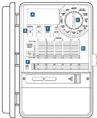
Figure 1: Front view of sprinkler liner
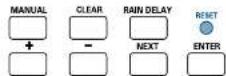
Figure 2: Programming Keys
Section 2: Getting Started
Programing the sprinkler timer can be aware pleased in just a few basic steps. Before you begin programming, it is important to:
• Install the batteries
+ Reset the sprinkler inner
- Select the preferred language
+ set the time of day and date
+ Determine a watering plan
Installing the Batteries
This sprinkler timer requires two AA alkaline batteries to store the program in memory during AC power loss. Fully charged batteries should provide sufficient power for approximately one year of protection. Annual battery replacement is recommended.
• Slide the battery cover to the left (No Figure 1)
• Insert two 5A alkaline batteries
- Replace the battery cover
Weeks in miss of batteries can cause the time, date, and program to be crossed after a power failure. If this happens, you will need to install fully charged batteries and reprogram the sprinkler timer. Note: batteries only relax the program to memory. They will not operate the waters in your sprinkling system.
Resetting the Sprinkler Timer
If this is the first time the spreader timer has been programmed, you should press the small recessed button labeled RESULT. Pressing reset does not affect the factory installed full-sale program. (See Figure 2) Do not press the reset button again unless you want to completely remove all your programming.
Select the Preferred Language
The language of the LCD display can be set for English, Spanish and French.
-
Turn the rotary dial to Language position
-
Press the RAIN DLY AV million size.
- Press the NEXT button until you reach the desired language [no: Figure 1]
+ Pre- ENTER to confirm your selection
- Press the RAIN DELAY Houston or Miami: I'm rotary and to send his movie.
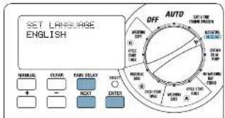
Figure 3: LCD Display Language Selection
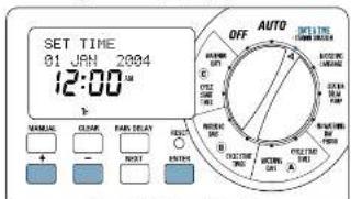
Figure 4: LCD Display Setting Time
Set the Time of Day and Date
Turn the rotary dial to the DATE & TIME position. See Figure 1!
- Press and hold the + button to advance the keys to the correct time of day. Use the - button to go in reverse. When the correct time of day is reached, press the ENTER button to lock in the time.
• Press the + and = barriers to set the correct year, then press ENTER.
• Press the + and - buttons to set the correct month, then press ENTER.
- Press the + and = without to set the correct date, then press ENTER.
The display will show the current time and date.
Condition: If a watering schedule is not entered into the weather times, the factory installed full safe program will turn on each station every day at 30 hours for 15 minutes. To avoid accidental watering, either turn the rotary switch to OFF or enter a watering schedule.
Determine a Watering Plan
To help you visualize how here to progress the exercise layer, it might be helpful to make a watering plan on paper. This will help you establish which days and times you want to water.
-
For each station (or valve) write down the watering location, the type of sprakler head and the plants to be watered.
-
Using this list, determine the recommended watering duration (for each type of sprinkler head and the vegetation to be watered) and frequency for each station.
Important, formally any proposed watering restrictions through your local water district.
- Determine, based on step 2, the ideal watering option for each station (Days at Week, Watering Interval or Odd/Exer Day-).
Based on the above information your water program may look like this.
| Station | Program | Watering Option | Days | Start Time | Duration Minutes | Location | Sprinkler | Plants |
| 1 | A | Days of Week | M, W, Sat | 5:00 AM | 15 min | Front Strip | Spray Heads | Grass |
| 2 | A | Days of Week | M, W, Sat | 15 min | Front, North | Spray Heads | Grass | |
| 3 | A | Days of Week | M, W, Sat | 15 min | Front, South | Spray Heads | Grass | |
| 4 | B | Dell/Even | Every other day | 6:45 AM | 30 min | Back, North | Clear Drive | Grass |
| 5 | B | Dell/Even | Every other day | 30 min | Back, South | Clear Drive | Grass | |
| 6 | C | Interval | Every 5 days | 9:00 PM | 30 min | Front | Shrub Head | Shrubs and Flowers |
Take the information above and record year water plan on the supplied label and place it on the inside of your timer.
Section 3: Programming
This sprinkler timer allows the flexibility of using 3 separate programs A, B, and C. You may program one or all based on your watering needs.
1. Start Times for Program A, B, or C
Note: The cycle start time is the time the program begins watering the first station. Cycle start times do not correspond to specific solutions. If you enter more than one cycle start time, all stations programmed to operate will water apart in sequence).
The way you set the cycle start time is the same for all programs. To say the cycle start times for each program you will be using, do the following:
- Param the very selector to the CYCLE START TIMES position in the program that you want to set up. The display will show on A or B or C depending on which program you have selected. (See Figure 5)
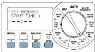
Figure 5: Setting start line
- See the time you want to begin watering for cycle start time. I using the + or - buttons, then press the ENTER button. For additional cycle start times, simply press NEXT to advance to the next cycle start time and repeat this procedure by using the + and - buttons to enter the time and then press ENTER.
Important. Additional start times will repeat the watering program. Generally, only 7 cycle start time is required for each program (A, B, or C).
Note: You cannot set a cycle start time for each startar. Stanone can be assigned to either Program A or B or C. Parte program can have up to four cycle start times. Stanone assigned to a program will run or sequentially according to the cycle start times assigned.
2. Selecting the Watering Frequency in Programs A, B, or C
This speaker timer will allow you to select watering frequency based on "Day(s) of the Week", "Intervals" (1 to 12 days), or "Did or Even Days". All at these options are available to use in program A, B and C.
By turning the dial to WATERING DAYS (in program A, B or C) the ICD displays the 1 watering options. See Figure 6!
• Mo Tu We Th Fr 5a Su applies to Day(s) of Week watering option
- Odd Even applies to the Odd or Even watering option.
- Interval applies to the Interval watering option
"DAY(S) OF WEEK" WATERING OPTION
The Day(s) of Wees option allows you to enter, specific days of the week to water (e.g. Monday, Wednesday and Saturday).
To set Day(s) of Week Option:
- Tarry the rotary dial to WATERING DAYS in A, B, or C.
- Press NEXT until the desired day of the week flashes. Press ENTER to select that day. Day(s) selected will have a water drop icon. 0 over the day of week. Continue until all the desired days are selected. (See Figure 7)
6
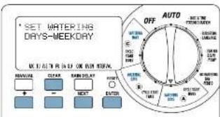
Figure 6: Selecting Watering Days
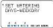
Figure 7: Selecting "Days of Week"
Important: ODD, EVEN, INTERVAL do not apply to Day (3) of Work monitoring option.
• To delete a day, previously selected, press the NEXT key until the day flashes and press the CLEAR button to a close set the day
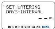
Figure 8: Selecting "Interval Wacing"
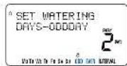
Figure 9: Selecting Odd/Lven Watering
"INTERVAL" WATERING OPTION
Interval watering is used to water at an interval from 1 to 32 days. An interval of 1 will water every day, an interval of 2 will water every other day, etc.
To set the watering "Interval":
- Turn the necessary dial to WATERING DAYS in A. B. or C. - Press NEXT until 'interval' flushes on the display. See Figure 31 - Select the 'INTERVAL' by pressing the + or - buttons to the desired interval number and press UNTLR.
- To remove a previous set interval, continue to press the NEXT button until INTERVAL flashes (in the lower right corner) and press CLEAR Enter a new interval to create it to press the NEXT button to select a different watering option.
"ODD OR EVEN WATERING OPTION
The sprinkler rimer can be selected to only water on Odd days at Even days. The odd-even schedule is based on the date. You can also choose to water an odd or even days with spaced intervals.
Example: if you select Odd days with an interval of 2. The program will water every other odd day (or every 1 day).
To set watering for ODD Days:
• turn the rotary dial to WATERING DAYS in A, B, or C.
- Press NEXT until 'ODD' flashes on the display. If you wish to water every aid day, press ENTER to confirm the programming. See Figure 91
- if you wish to water on odd days (our less frequently than every other day, press + or = to set the interval from 1 through 5 for watering).
- Press ENTER to save
To set watering for Even Days protocol with the above steps but select 'EVLN' on the display.
Note: The sprinkler timer will NOT water on the first day the program is entered or modified if the start time(s) have already passed.
3. Set Watering Durations
This sprinkler timer allows 2 ways to set water duration for each station.
SLIDE SWITCH
- Slide each Water Duration Slide Switch to me desired rate (from 2 to 120 minutes) for each station. See Figure 10 ^1
DIAL SET BY MINUTE
A watering duration can be set in one minute increments. To do so you must use the Dial Set by Minute function. The "Dial Set by Minute" station duration can be set for each individual station.
- Slide the Watering Duration Slide Switch to the DIAL SET BY MINUTE position (indicated by the said where bar) for each station. See Figure 11.
• Turn dial to the •STATION DURATION.
- Press RAIN DELAY button to access the Station Duration Function.
• The LCD will allow you to set the watering station ice station
- Using the + or - enter the watering duration for station 1 and press ENTER to save.
- Proceed and enter watering durations for the remaining stations. - To delete the water duration for a station, press ENTER until the station appears in the LCD then press CLEAR.
Important if the slide switch is not in the "Dial Set By Minute" position, the never will not use the entered duration.
Note: The watering duration setting will be used by programs A, B and C. You cannot enter different watering durations for program A, B and C. TIP-
- To inactivate a station, move the side switch to the MANUAL OFF position.
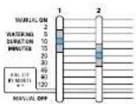
Figure 10: 'Slide Switch durations' set at 10 minutes and 20 minutes
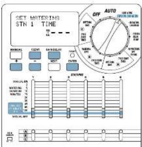
Figure 11: "Dad Set by Minute"
PROGRAM SLIDE SWITCHES
The Program Slide Switches allow you to select a program (A, B or C) for individual stations. (Pre Figure 12)
Using information collected, in "Establishing a Water Plant" on page 3, select program "A", "B" or "C" for each station.
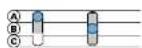
Figure 12: "Program Slide Switches" set an program A and B
REVIEWING AND CHANGING YOUR PROGRAM
I've Hydro-Ram® surfider under allows us easy to review watering plan. For example, to review Program A* watering cycle start times, simply turn the story selector to the CYCLE START TIMES position in Program A* and check the times that have been entered. Using the NEXT button, you can advance through the schedule with out fear of detuning any programming.
If you want to change the cycle start times, watering days, or watering intervals, simply follow the intentions for that program modification. After reviewing or changing a watering schedule, remember to turn the worry salientor back to AUTO if you want to speakler times re-automatically follow your plan.
Section 4: Automatic Operation and
Commonly Used Features
Cautism: This appliance is not intended for use by young children or infirm persons without supervision. Young children should be supervised to ensure that they do not play with the appliance.
Ready for Automatic Operation
After programming is complete, turn the rotary selector to AUTO. The speaker timer is now fully programmed and ready to use in the automatic mode. In automatic mode, each station will operate sequentially, starting with Program A.
IMPORTANT: This timer contains a Rain Sensor Bypass Switch. If the rain sensor switch is in the "on" position and no sensor is connected the sprinkler timer will not operate.
Station Advance
When the speaker time is watering, press NEXT to end watering at the current station and move or to the next station.
Timer Off
Turn the Rotary Dial to the OFF position. This presents the springer timer from wzzing in Automatic and Manual modes.
Rain Delay
Rain delay allows you to delay your sprinkler time from watering for a set period of time. Delay settings are 2-, 13, and 72 hours and from 4-40 days.
ACTIVATE THE "RAIN DELAY" FUNCTION:
-
Ensure the rotary selector is on the AUTO position
-
Press the RAIN DELAY burton to automatically delay watering for 24 hours. [See Figure 13]
-
If a longer Rain Delay is desired, use the + or - button to increase or decrease the setting
-
Press INTUR or wait 30 seconds and the selected Rain Delay will begin.
-
The CLEAR button stops the run Delay and scheduled watering will restore.
At the end of the seriesed Rain Palay section of time, automatic watering restumes.
Note: Manual watering will override Rain Delay. When manual watering is complete, the Rain Delay will resume.
While in rain delay mode, the sprinkler timer will display the remaining hours. No other buttons, besides CLEAR, will be accepted while the sprinkler timer is in the rain delay mode.
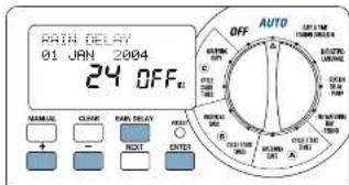
Figure 13: "Bair Delay" set for 24 bars
Water Budgeting
Water budgeting is a simple way to adjust your watering duration to match seasonal watering needs. Water Budgeting works by increasing or decreasing watering duration for all strains in all programs. Adjustment range is from 20% to 200% by increments of 10%. The default value is 100%.
TO SET BUDGETING:
-
Turn rotary dial to •BUDGETING position (See Figure 14)
-
To increase or decrease the percentage, press the + or - button.
-
Press ENTER to save setting.
Section 5: Manual Operation
The Hydro-Raiz® sprinkler later allows you 2 options to operate your sprinklers manually.
Single station
Multiple stations
Note: If a manual operation is started during an automatic program cycle, the automatic program cycle will be cancelled.
Single Station
This option is most commonly used, for testing a specific station or for additional watering of a specific station. Manual operator is accomplished by using the Watering Duration Slide Switches.
Important: Only one station will be active at a time. The last station set to the MANUAL ON position will be active (wattening).
SINGLE STATION—WITHOUT WATERING DURATION
- Ensure the rotary selector is on the AUTO position.
- To activate the station, move the station Watering Duration Slide Switch to the MANUAL ON position (fully up). The display will indicate "MANUAL ON" and the station member being activated. [See Figure 15]
A turn off mental watering, move the Watering Duration Slide Switch to the MANUAL OFF position.
Remember to return the Watering Duration Slide Switch to the Watering Duration previously set for automatic operation.
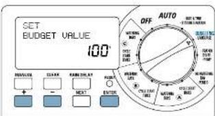
Figure 1±5 set "Water Budgeting"
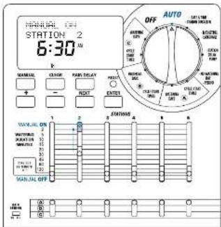
Figure 15: Manual Watering, One Station
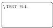
Figure 16: Display 'Test Cycle' selected
SINGLE STATION WITH WATERING DURATION
-
Follow steps 1 and 2 above.
-
Move the station Watering Duration Slide Switch to the desired watering duration.
-
When watering is complete, return the Watering Duration Slide 5 switch to the Watering Duration previously set for automatic operation.
Multiple Stations
This option is most commonly used during uneosensibly dry or hot weather. This option allows you to manually water without adjusting and resetting the Watering Duration Slide Switches.
MANUAL TEST
This feature allows the homeowner to run each station 1 minute to confirm all stations are working properly.
To Run a Test Cycle:
-
Ensure the rotary selector is on the AUTO position
-
Press the MANUAL button once [See Figure 10]
- Press INTUR to begin, and CLLAR to stop test cycle.
Note: This fixation will activate all stations even twice with the side control of the manual off-positive.
MULTIPLE STATIONS—WATER ALL STATIONS ONCE
This can be especially helpful if you happen to experience an orally warm weather. Each station will water once, in sequence, based on each station's Watering Duration setting.
Note: Program settings 14, 8, or 15 will not affect whether a station waters or mix. If you do not want a station to water, move the Watering Duration Slide Switch at the MANUAL OFF position.
- Ensure the rotary selector is on the AUTO position.
- Press the MANUAL button once.
- Continue to press the NEXT button until you see "A B C Extra All" (See Figure 17)
-
Press the ENTER button, within 30 seconds, to activate manual watering.
-
To internal or discontinuous this cycle, press the CLEAR
at least once
At the completion of this function, the sprinkler timer reverts back to your normal automatic watering plan
Note: If the manual operation is started during an automatic program cycle, the automatic program will be cancelled.

Figure 17:
Display showing manual watering for all prepared and all active stations
MULTIPLE STATIONS—WATER ONLY STATIONS ASSIGNED TO A SINGLE PROGRAM (A, B OR C)
For this example we will water all stations assigned to Program B. This procedure will be the same for both Program A and C.
Ensure the rotary selector is on the AUTO position
-
Press the MANUAL button once.
-
Continue to press the NEXT buttons until you see "B EXTRA ALL" See Figure 12
-
Press the ENTER button, within 30 seconds, to activate manual water tap
-
To interrupt or discontinue this cycle, press the CLEAR button once.
Note: In this example, searches assigned to Program "3" will water one at 0 time in sequence.
EXTRA ALL
Figure 18:
Display showing mental watering, for stations assigned to program B, selected
Section 6: Additional Features
No Watering
"No watering" allows the homeowner to input the restricted water day(s) calendar period (time), imposed by local water districts. This feature prevents the homeowner from watering during restricted days and times.
"NO WATERING" DAYS) OF WEEK
When restricted day(s) are entered, all watering programs that fall on a restricted day will not water on that day.
To program "No Water Day(s)"
-
Turn the rotary call to NO WATERING
-
Press the NEXT button until the desired day of week fashes and press CLEAR. [See Figure 19]
Note: Days entered as No Watering days will NOT have a water drop iron above the day.
-
Repeat step 2 until the water drop icon is removed above all restricted days.
-
To remove a "No Watering" restriction from a day press the NEXT button until the day flashes and press the ENTER button.
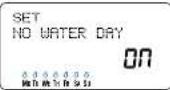
Figure 19: Display - "No Water Day"
"NO WATERING PERIOD/TIME"
When a restricted time is entered, all watering programs that will on a restricted watering time will be shifted to a non-restricted day and/or air.
To program "No Watering Period/Time"
-
Turn the rotary dial to NO WATERING
-
Press the RAIN DELAY (in mm) once. (See Figure 20)
-
Later the starting time of the 'No Water Period' using the +
SEA = buttons and press ENTER to accept time.
+ New set the ending time of the "No Water Period" using the + and - buttons and press ENTER to accept time.
- Return rotary dial to the AL10 posterior
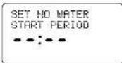
Figure 20: Display - No Water Period.
Set Master Valve or Pump Start
This sprinkler timer allows each station to operate with or without pump. If a station is set to operate with the pump, it will start two seconds before the station goes.
Note: A Pump Start Relay is required to operate pump (Sold separately)
TO ACTIVATE "PUMP START" FOR EACH STATION:
-
Turn the rotary dial to the •PLMT position
-
Press the RAIN DELAY button force. (See Figure 21)
-
If you want the pump to be active for the displayed station, press ENTER.
-
If you do not want the pump to be active for the displayed station press CLEAR.
-
Press NEXT to advance to the next station.
-
Turn the rotary fluid to exit this setting.
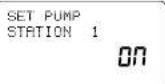
Figure 21: Display - Pump Start active for station 1
Station Delay
This feature is certainly used by homeowners with water or well water. The delay allows criteria and well's adequate time to re-supply the reservoir.
Note: Delays between stations can be programmed from 1 minute to 2 hours. TO PROGRAM STATION DELAY:
: Turn the rotary dial to •STATION DELAY (See Figure 22)
2. To increase or decrease the time delay time between each sta-
tion, press the + or = button.
3. Press the ENTER button to save the time delay setting.
1. Return the rotary dial to AUTO
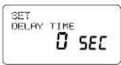
Figure 22: Disp x_i = Station Delay
Section 7: Installation of Indoor Mount Sprinkler Timer
Before installation please have the following items and tools.
• 2 AA Batteries
• Phillips Screwdriver
- W/6 Strippers
Installing the sprinkler timer in 5 easy steps
1 Selecting Location
- Mounting Ice Sprinkler Timer
1+
-
Installing the Batteries
-
Connecting the Power Supply
-
Caroasting Valve Wires to Screwler Toner
Note: For installation of OUTDOOR models see Appendix A
1. Selecting a Location
Select a location with the following cinema:
- New an electrical outlet (Avail) using an outlet controlled by
a switch
• An indoor, dry location, where operating temperatures are no:
below 32° of above 150° collenell (0 degrees or above 10
• Avoid direct sunlight
- Access to springer wire (from valves)
2. Mounting the Sprinkler Timer
• Using the mounting template (included) mark the screw
locations on the wall.
- insert a No. 5 screw (incluka) in the upper mark, leaving the
Screw has an axial tilt, 3000 ft incl. the wall (use expanding anchor in plaster or wafery of necessary).
- For the unknown point in the local the entire place over the
ex. endal siew. [See Figure 23]
- Screw a No. 9 screw through the two holes located behind the
bananes in the battery compartment.
3. Install the Batteries
Two AA alkaline batteries are required to retain the program in memo-
using power-kiss. Arundi replacement (e-terminerola).
+ Remove the battery cover by shading to the left. [arc. Figure 24]
- Insert two AA alkaline bacteria
• Replace the battery power
Note: Batteries clean will not operate the valves or your sprinkling system. The 21-well transformer must be plugged in and have power to operate your system normally.
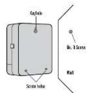
Figure 23: Mounting the Sprinkler Timer
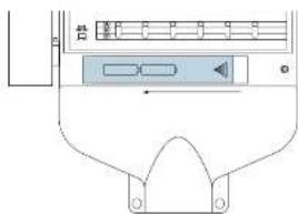
Figure 24: Battery Compartment
4. Connecting the Transformer
- With the cover oil, find the two terminal boxes labeled
-24VAC IN [the Figure 2]
• Insuring the transformer is not plugged in; seen; one of two
Notes: if may be necessary to open the terminal to name for wire insertion or removal. This is alone by pressing upward on the tab located in top of the terminal.
• Play in the transformer.
Warning: Do not link two or more sprinkler tigers together with one transformer.
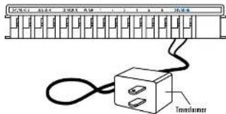
Figure 25: Connecting the Transformer
Section 8: Wiring Valves, Sprinkler Timer, Pump Start and Master Valves
1. Wiring the Electric Valves
Note: If the distance between the sprinkler times and values is under 700° (210 m³, use Hydro-Katz® sprinkler were or 20 gauge (AWG)) plastic partitioned thermostat wire to connect the sprinkler time to the values. If the distance is over 700° (210 m³, use 16 gauge (AWG) wire.
- Taking the spinkler wire, step 1/2" (12mm) of the plastic installation off the end of each individual wire
- Connect one wire from each valve (it doesn't matter which wire) to a simple "Common" sprinkler wire (usually white) [see Figure 76]
Important: All wires should be joined together using wire mugs, sellers, reader vinyl taps. For additional protection to waterproof connectors, on Hydru Rain® grease cap can be used. - Next connect the remaining wire from each valve to a separate colored speaker wire.
• To avoid electrical hazards, only one valve should be connected to each station.
Important: The wine can be buried in the ground, however, for more protection wines can be pulled through PVC pipe and buried underground. He careful to avoid impinging the wires in locations where they could be damaged by digging or treaching in the future.
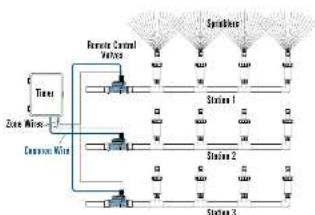
flowchart
graph TD
    A["Remote Control Valve"] --> B["Station 1"]
    A --> C["Station 2"]
    A --> D["Station 3"]
    E["Tissue"] --> A
    F["Zone Width"] --> A
    G["Common Width"] --> A
    H["Spindle"] --> A
    I["Water"] --> A
    J["Water"] --> A
Figure 26: Connecting, Sprinkler Wires to Valves
2. Connecting Valve Wires to the Sprinkler Timer
- Remove the terminal compartment cover.
- Strip L4F (6 mm) to the plastic installation off the end at each wire.
- Determine which value you want to connect to which station. Connect each specialer wire (excluding the "Common" wire) to a separate station terminal (numbered above each blue tab) by inserting the bore wire fully into the bore under each air. (See Figure 27)
- It may be necessary to open the terminal to allow for wire insertion or removal to do this, simply press upward on the tab located on top of the terminal.
- Can act the carbon wire to the terminal (white in color) labeled "COMMON"
Note: Only insert one wire into each terminal. If more than two common wires are required, space several together so only one wire now into each of the two "Common" terminals. Photo? The split connection made a wire out.
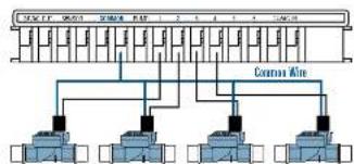
flowchart
graph TD
    A["Component Air"] --> B["Component 1"]
    A --> C["Component 2"]
    A --> D["Component 3"]
    A --> E["Component 4"]
    A --> F["Component 5"]
    A --> G["Component 6"]
    A --> H["Component 7"]
    A --> I["Component 8"]
    A --> J["Component 9"]
    A --> K["Component 10"]
    A --> L["Component 11"]
    A --> M["Component 12"]
    A --> N["Component 13"]
    A --> O["Component 14"]
    A --> P["Component 15"]
    A --> Q["Component 16"]
    A --> R["Component 17"]
    A --> S["Component 18"]
    A --> T["Component 19"]
    A --> U["Component 20"]
    A --> V["Component 21"]
    A --> W["Component 22"]
    A --> X["Component 23"]
    A --> Y["Component 24"]
    A --> Z["Component 25"]
Station Valves
Figure 27: Connecting Sprinkler Wine
3. Pump Start & Master Valve
This sprinkler timer allows a master valve or pump start relay to operate whenever a station is an.
Note: If you are activating a poop from this water, you must purchase a Pump Start Roller.
From the pump start relay (or master valve): connect one wire to the 'Pump' terminal and the other wire to the 'Common' terminal. For Figure 29,
Section 9: Diagnostics Circuit Breaker
Smart-Scan® Diagnostic Fault Sensing
A proposed fourth series will automatically scan for the presence of a faulty silenced or wiring short in a valve during each wasting sequence. If a faulty station is directed, the sprinkler inner will move to the next working station. Smart-Ston. ^8 also detects faulty wiring for the Pump or Master Control. Upon detection wasting cycle is discontinued
Fault Notification
- Facility Station - "FAULT STN" and -station number, is displayed. Note: When multiple faulty stations are detected, only the best facility station will be displayed.
- Faulty wiring for pump/master control - PUMP FAULT is unplayed.
Correcting the Fault:
- First repair the shoot in the wiring or replace the lacy salesoid.
- Test the station by operating a manual watering sequence.
- If the short is not detected after a few seconds, the fault notification message will be terminated
- If the message carries, a short in the wrong still exists.
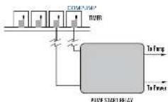
Figure 28: Connecting pump seat or master valve.
Internal Auto-Resetting Electronic Circuit Breaker
The sprinkler timer is equipped with an internal electronic self-resetting circuit breaker
Possible cause of a circuit breaker tripping
- If lightning strikes nearby.
- When the power supply has an electric spike.
- It a station has a wiring sheet.
Wherever use of these conditions necessary, the electronic circuit breaker may trip cars at the station airport from the sprinkler timer to be halted momentarily. The batteries will continue to store the program information and activate the LCD. After a few moments, the sprinkler timer will automatically reset the circuit to see if the condition has stopped. If so, the circuit breaker will reset itself.
Section 10: Trouble Shooting
| Symptom Cause Correction | |||
| LCD Displays | POWER RESET FAULT STN | Power Surge Fairly surround | See Page 3 Replace |
| Short in sprinkler wire | Check wire connections | ||
| Look for cuts in sprinkler wire or replace | |||
| PUMP FAULT | Short in sprinkler wire going to pump | Look for cuts in sprinkler wire or replace | |
| NO AC | Transformer not plugged in under modelled | Ensure transformer is securely plugged in | |
| Permanent wiring is not connected or connected improperly together modelled | See Page 21 | ||
| Main horizontal power is not on | Check circuit breaker or fuse | ||
| Drink or cardix LCD | Missing or use battery and use AC power | Check batteries and check AC power | |
| Reset button needs to be pushed | Re-enter program(s) | ||
| Watering Problems | One or more stations do not turn on | Programming incorrect | See Page 6 |
| Flow control stem can valve is turned off | Clock valve | ||
| Watering Duration Slide Switch is on MANUAL OFF | Slide the switch to a connecting duration | ||
| Watering Duration Slide Switch is on B. AL SET BY MINUTE | Enter a watering duration (Size page 8) or slide the switch to a connecting duration | ||
| Programm Slide Switch is not on the correct Program (A, B, C) | Slide the Program Switch is the correct program | ||
| Spindler Wire lasts connected to timer or valve | Connect wiring | ||
| The rotary shot is not on bus | Turn the slot to Auto | ||
| Water Supply is not supplying water | Make sure water level is turned on | ||
| Stations turn on when they are not supported to | Excessive Water Pressure | Install a pressure regulator | |
| More that one start time is programmed and/or with overlapping start time's "programm?" | Review programming (Size page 91 | ||
| Water Restillations program is preventing watering | See Page 12 | ||
| Station Delay assistance | See Page 14 | ||
| A Station will turn off | Watering Duration Slide Switch is on MANUAL ON | Slide Watering Duration Slide Switch to MANUAL ON | |
| Valve may be clugged by details | Clean Valve | ||
| LCD shows existing program morning but sprinklers do not turn on | Main Sensor Bypass switch is "OFF" but no rain sensor is connected. | Turn rain sensor switch "OFF" | |
Glossary of Terms
| TERM DEFINITION | |
| Controller | See sprinkler timer |
| Cycle Start Time | The time the program begins watering the first station |
| Irrigation Valve, Automatic | Used in conjunction with sprinkler timers and are a convenient way of delivering water to lawns, plants and gardens |
| Master Valve | A valve that prohibits water from reaching "Station Valves" |
| Multiple Start times | A feature that allows a program to be operated multiple times on the same day |
| Overlapping Programs | When a "Start Time" is set before the previous program has completed |
| Program (A, B or C) | Consists of 1 or more "Start Timers," a "Wastering Option" (Days of Week, Interval or Odd/Even Days) and what stations will water |
| Rain Delay | A feature that prevents the sprinkler timer from running it's scheduled watering program for a specific duration |
| Solenoid | The electrical part on an irrigation valve that opens and closes the valve |
| Sprinkler Timer | A device that is responsible for turning an automatic irrigation system on and off |
| Station | An area where the irrigation is all controlled by a single control valve |
| Valve | See irrigation valve |
| Watering Option | Consists of Days of Week, Interval or Odd/Even Days use in programming |
| Watering Program | Soc program |
| Watering Restriction | Specific days and/or times that local municipalities prohibit watering |
| Zones | Soc station |
Appendix A: Installation of Indoor-Outdoor Sprinkler Timers
1. Selecting a Location
select a lacrion with the following criteria:
- Near a power source (if hard wiring) or electrical outlet
(applicable only to U.S. retail riners)
• A location, where operating temperatures are not below 32° or
above 108. Fahrerheit (0 degrees or above 70 degrees Celsius)
• A location, with at least 7° of space is to the left of the sprinkler
timer has for the dear to swing oper after installation
Note: The sprinkler covers are weather-resistant to UL-50 and FTI® Listen, but should not be placed in areas where continuous water could cause damage.
• A location without a river/sandlight
- Access to sprinkler wire (from valves)
Caution: Do not open the Sprinkler Timer when it is raining.
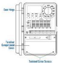
Figure A1: Terminal Cover Figure
2. Mounting Sprinkler Timer
- Using the mounting template (enclosed) mark the screw locations on the wall.
- Insert a No. 6 screw (included) in the upper mark, leaving the
A screw head about 1.0 inch (500") and the wire wall. (02
Expanding sixtons in part of slurry is necessary.
+ Remove the "Terminal Cover" By air-screwing, the two screws and pulling the plastic cover forward, this reveals the "AC Sub Plate", [Sai Jugun A1]
- Remove the "Rubber Weather Plug" from "AC Sub-Plate" (See Figure A2)
- Slip the slotted keyhole, in the back of the Sprakier Timer. from The screw. (pre Figure 41)
- Making sure the Tumer is level, place a No. 3 screw (included) to the center depression (located in the hole where the middle plug was located) and tighten until the box is held, firmly to the wall, but do not over-tighter.
To make installation easier the Sprinkler Timer has a removable door.
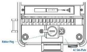
Figure A2: AC Sub Plate
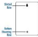
Figure A3: Back of Sprinkler Timer
3. Connecting Electrical Power
Caution: For outdoor installation, it is recommended that a qualified electrician completes starting in accordance with electrical codes and regulations. This scientific timer is intended for use with a Ground Four interruptor for 3 protected circuit when used outdoors.
Check the model number of your sprinkler under various models are configured differently to meet national requirements. The model number can be found on the back of the housing, together with other asked information.
I FIND YOUR MODEL BELOW AND GO TO THE APPROPRIATE SECTION.
Models 57390, 57192, 57184, 57186, 57388, 57382
• Go to be filled Line Lord section below
Models 57606, 57812, 91016, 91012
- For indeed amounting go to Fitted Line Cord Installation
section below
- For Outdoor mounting go to Preparing for Perimeter, Waring
sected below
Models 57341, 57346, 57348, 57342, 91022, 91026, 91028
• Go to "Permanent Writing" section
FITTED LINE CORD INSTALLATION
Replacement of the supply Cord. If the supply cord is damaged it must be replaced by a service agent or similarly qualified person in order to record a hazard.
- Indoor Locations - User the line card into Ground Fault
Interraper (GFI) outlet
+ OutdoorLocations - Insert the line card into a power Ground
Fault Interrupter (GFI) outlet connected to a GFI circuit
• Proceed to Section 6 on page 15
PREPARING FOR PERMANENT WIRING
- Remove the "Terminal Cover" by unscreening the two screws and pulling the plastic cover forward, this reveals the "AC Sub-Plate" [56 Figure 30]
- Remove the 'AC Sub-Plate Cover,' by removing the screw (drated to the right of the rubber plug).
+ Loaten the screw on the 'Cord Restraint' and the three screws on the terminal block and remove the 'Line Cord' completely. (See Figure A4)
- Feed the three "Pigtail" wires at the digitail through the "Exit Nipple," under the "Cord Restraint", and across to the terminal block. Gones the wires to the "Terminal block" in the following manner:
Black "pgrall" wire - Correct to the 1-termable (lot)
White "pigtail" wire Connect to the 'N' terminal (Neural)
Cass: "gietail" wire - Carney to the "E" Terminal (Grassail).
- Ensure that the terminal screws and the 'Cord Restraint relief screw are all linely tightened.
- Replace the AC Sub-Plate and tighten screw (I'd not force into
place, it resistance is met check that no wires are trapped?
+ Proceed to 'Installation on using Permanent Wiring'
INSTALLATION USING PERMANENT WIRING
Important: The sprinkler user has a ball in transformer that must be connected to an AC low-willage source. Check the back of the sprinkler driver has for power requirements. Local building and electrical codes usually require that an approved electrical conduit and electrical firings are used to connect exercise multi-mounted equipment to AC power. Please check local codes. Any permanent connection should be made by a licensed electrical contractor to accordance with the requirements of the National Electrical Code and other state and local codes.
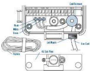
Figure 4: Receiving "Line Cord"
Caution: Do not correct the sprinkler timer to one phase of a three-phase power system used by a power or other electrical equipment.
Important: This sprinkler water has an Exit Nipple mounted external power connection, the this 1/2 inch (1.5mm) NIP apple to connect the sprinkler timer to a standard electrical junction box (UL Listed or equivalent or couple with 0.5 cm (5V standards or equivalent).
- Turn of the AC power at the AC circuit breaker and apply an appropriate safety lockout. Verify that the power has been turned off to the installation site using an AC voltmeter set for the correct measurement range.
- Use power feed were of 14 pages (AWG) minimum with a temperature rating of 155 degrees Fahrenheit (60 degrees Celsius) or higher.
- Install the conduit and associated fittings. Connect the AC electrical power wiring to the source by following all the right codes and local standards.
-
Connect the junction box (not included) to the NFT ripple [See Figure A3]
-
Connect the source power conduit to the entrance of the junction bus, following all the appropriate codes.
- Connect the source wires to the wires extending from the sprinkler timer
Take care to follow the correct solar code. For LAC connect the Green for Ground, Black for Live, and White for Neutral. Often the source ground may be bore copper conductor rather than green wire. For Europe: Live is Brown and Neutral is Blue; there is in ground cutaneous required. Be sure that all wires are connected to the proper source wire. - Make sure all connectors are made with code approved insulated connectors.
- Pre sure to place a weatherproof gasket and aid on the junction box.
- Fraced to Section 5 on page 13
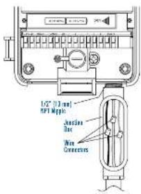
Figure A5: Using a Junction Box
Appendix B: Rain Sensor and the Rain Sensor Bypass Switch (Sensor sold separately)
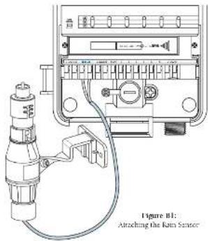
A rain sensor or other type of micro-switch weather sensor may be connected to the sprinkler timer. The purpose of the sensor is to stop watering when precipitation is sufficient.
CONNECTING A RAIN SENSOR
- Connect the rain-sensor wires to the writing terminal ports (yellow in color) labeled 'Sensor' [See Figure 61]
Note: Refer to your own sensor manual for specific training instructions.
- Place the sensor output switch to the 'on position to begin operation.
RAIN SENSOR BYPASS
This sprinkler inner is equipped with a sensor override "out/off" switch. This switch is for adjusting maintenance and repairs, so the sprinkler inner can be operated even if the rain sensor is in active mode.
IMPORTANT: If the rain sensor switch is to the "on" position and no sensor is connected, the spoolider timer will not operate. To resume spoolider timer operation place the switch in the off position.
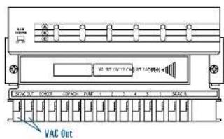
24 Volt Output Terminals
Hydro-Rain® Irrigation has equipped this sprinkler timer with 2 VAC output terminals. This allows direct 2 volt connection to the Sensor, avoiding the need to run a separate power source. This is not an input terminal and should only be used with an Environmental Sensor.
Caution
- Before connecting the sensor to the 24 VAC output terminals, two of the power sources to the variable time
- Only exercise, sensors requiring 24 vots. Connecting any device net 24 vol. may cause damage to both sprinkler inner and sensor.
- Please consult with the manufacture of the sensor you are attaching.
- The appliance is not intended for use by young children or informal persons without supervision
- Young children should be supervised to ensure that they do not play with the appliance
Help
Before returning this series letter to the stone, print Hydra-Rain ^b Technical Service as: 1-800-489-6156, 1-801-239-7555
Listings
The sprinkler timer is tested to UL-1931 (Models 57204, 57206, 57208, 57122) and UL-50 (Models 57206, 57012) standard and is LT. ^ based. Appropriate international models are CSA ^ and CL ^* approved.
Trademark Notice
Control Scar ^® , and Smart Scar ^® are registered trademarks of Hydro-Rain ^® Irrigation Products, Inc. The information in this manual is primarily intended for the user who will establish a watering schedule and enter that schedule into the sprinkler timer. This product is intended to be used as an automatic sprader timer for activating 24 VAC irrigation valves, as described in the manual.
Hydro-Rain ^® Irrigation Limited Six Year
Warranty
Hydro-Karv ^® Irrigation Products, Inc. warrants to its customers for us products will be first from debate in materials and workshop for a period of six years from the date of purchase.
We will replace, free of charge, the defective part or parts found to be defective under normal use and service for a period, et up to six years after purchase (proof of purchase request).
We reserve the right to inspect the defective part prior to replacement. Hydro-Rain® Brixpictor Products, Inc. will not be reasonable for consequential or incidental cost or damage caused by the product failure. Hydro-Rain® liability under this warranty is limited solely to the replacement or repair of defective parts.
To increase your warranty, returns the mail to your dealer with a copy of the sales receipt.
Safety of children: The controller is not intended for use by young children or infirm person without supervision. Young children should be supervised to ensure they do not play with controllers.
ESPAÑOL
5.2b. EFEACED was a type of choice
natural_image
Pure technical diagram of a mechanical component without any text, numbers, or symbolsnatural_image
Technical line drawing of a mounted electrical meter with attached cable and connector (no text or symbols)VAC Out
Consejo
- INSTALLATION MANUAL/USER'S MANUAL
- Table of Contents
- ENGLISH
- ESPAÑOL
- Controls Commonly Used
- Digital Display with Text Messaging
- Programming Buttons
- Rotary Dial
- sotinsler timer
- Slide Switches - Watering Duration
- Program Slide Switches
- F Rain Delay
- Section 2: Getting Started
- Installing the Batteries
- Resetting the Sprinkler Timer
- Select the Preferred Language
- Set the Time of Day and Date
- Determine a Watering Plan
- Section 3: Programming
- Start Times for Program A, B, or C
- Selecting the Watering Frequency in Programs A, B, or C
- "DAY(S) OF WEEK" WATERING OPTION
- To set Day(s) of Week Option:
- "INTERVAL" WATERING OPTION
- To set the watering "Interval":
- "ODD OR EVEN WATERING OPTION
- To set watering for ODD Days:
- Set Watering Durations
- DIAL SET BY MINUTE
- REVIEWING AND CHANGING YOUR PROGRAM
- Section 4: Automatic Operation and
- Commonly Used Features
- Ready for Automatic Operation
- Station Advance
- Timer Off
- Rain Delay
- ACTIVATE THE "RAIN DELAY" FUNCTION:
- Water Budgeting
- Section 5: Manual Operation
- Single Station
- SINGLE STATION—WITHOUT WATERING DURATION
- SINGLE STATION WITH WATERING DURATION
- Multiple Stations
- MULTIPLE STATIONS—WATER ALL STATIONS ONCE
- MULTIPLE STATIONS—WATER ONLY STATIONS ASSIGNED TO A SINGLE PROGRAM (A, B OR C)
- Section 6: Additional Features
- No Watering
- "NO WATERING" DAYS) OF WEEK
- "NO WATERING PERIOD/TIME"
- To program "No Watering Period/Time"
- Set Master Valve or Pump Start
- Station Delay
- Section 7: Installation of Indoor Mount Sprinkler Timer
- Selecting a Location
- Mounting the Sprinkler Timer
- Install the Batteries
- Connecting the Transformer
- Section 8: Wiring Valves, Sprinkler Timer, Pump Start and Master Valves
- Wiring the Electric Valves
- Connecting Valve Wires to the Sprinkler Timer
- Pump Start & Master Valve
- Section 9: Diagnostics Circuit Breaker
- Smart-Scan® Diagnostic Fault Sensing
- Fault Notification
- Correcting the Fault:
- Internal Auto-Resetting Electronic Circuit Breaker
- Appendix A: Installation of Indoor-Outdoor Sprinkler Timers
- Mounting Sprinkler Timer
- Connecting Electrical Power
- PREPARING FOR PERMANENT WIRING
- INSTALLATION USING PERMANENT WIRING
- Appendix B: Rain Sensor and the Rain Sensor Bypass Switch (Sensor sold separately)
- Volt Output Terminals
- Help
- Listings
- Trademark Notice
- Hydro-Rain ® Irrigation Limited Six Year
- Warranty
- Consejo
Brand : Hydro-Rain
Model : 04044
Category : Automatic watering