Master Creator Kit Booster - Uncategorized Infento - Free user manual and instructions
Find the device manual for free Master Creator Kit Booster Infento in PDF.


User questions about Master Creator Kit Booster Infento
0 question about this device. Answer the ones you know or ask your own.
Ask a new question about this device
Download the instructions for your Uncategorized in PDF format for free! Find your manual Master Creator Kit Booster - Infento and take your electronic device back in hand. On this page are published all the documents necessary for the use of your device. Master Creator Kit Booster by Infento.
USER MANUAL Master Creator Kit Booster Infento
natural_image
Modern bicycle with silver frame and red wheels, no visible text or symbolsLength 90-112 cm / 35-44 inch
Max weight 20kg / 44 lbs
Time to build 3 hours

text_image
infentoWorld's first real constructible rides

WARNING - IMPORTANT NOTICE TO PARENTS
Before you start constructing and use our product, please carefully read the following safety warning and download our manual from our website. This safety warning and manual contains important information relating to your child's safety. It is your responsibility to review this information with your child and make sure they are fully aware of all the warnings before they start riding. Failure to follow instructions and safety precautions can result in serious injury or death.
You can find a digital copy of the manual at the following web address:
www.infentorides.com
PLEASE PRINT OUT THE MANUAL AND KEEP THE MANUAL AND THIS SAFETY WARNING IN A SAFE LOCATION FOR FUTURE REFERENCE.
SAFETY SECTION


WARNING! PARENTAL SUPERVISION AND APPROPRIATE USE
Like any moving product, rides made from Infento parts can be dangerous if due care and attention is not paid. To reduce the risk of serious injury: use only under close adult supervision. Parents must review the following warnings and instructions with each Infento ride that is being build. It is your responsibility to review this information and make sure that all riders understand all warnings, cautions, instructions and safety topics, and assure that young riders are able to safely and responsibly use this product. Infento recommends that you periodically review and reinforce the information in this manual with younger riders, and that you inspect and maintain your child's Infento rides to insure their safety.

WARNING! RIDING ON INFENTO RIDES CAN BE A DANGEROUS ACTIVITY
Riding on Infento rides can be a dangerous activity. Certain conditions may cause the equipment to fail without fault of the manufacturer. Rides made from Infento parts can and are intended to move, and it is therefore possible to lose control, fall off and/or get into dangerous situations that no amount of care, instruction or expertise can eliminate. If such things occur you can be seriously injured or die, even when using safety equipment and other precautions. Ride at your own risk and use common sense.

WARNING! NO LIABILITY FOR CONSTRUCTED RIDES THAT DIFFER FROM OUR MANUALS
The rides that you can find in our manuals have been tested by official independent testing agencies. We will not be responsible or liable, directly or indirectly, in any way for any loss or damage of any kind incurred as a result of your decision to build constructions or rides that differ from the official rides that we show in our manuals.
ASSEMBLY - SUBSECTION

WARNING! OUR KITS CONTAIN SMALL PARTS
This package contains small parts which, before assembly, present a choking hazard to children under the age of three. Care should be taken during unpacking and assembly to insure that all small parts and plastic bags are accounted for and kept out of the reach of children.

WARNING! TO AVOID SERIOUS INJURY:
- Construction/assembly of a ride should always be under supervision of an adult using the Infento manual for the specific ride.
- All fasteners (bolts and nuts) should be fully tightened.
- It is the responsibility of the adult who assembles this bicycle to properly install all parts included in the factory sealed shipping carton and to make the adjustments to the functional parts such as handle bar and seat and chain when necessary.
USE - SUBSECTION

WARNING! TO AVOID SERIOUS INJURY:
- Continuous adult supervision is required.
- Only ride constructed rides that have been built according to the instructions given in the official Infento manual.
- Never exceed the maximum weight. You can find the maximum weight for every specific ride in our manual.
- Always check the manual to see the minimum and maximum age as well as the minimum and maximum length for every specific ride.
- Always wear safety equipment such as a helmet, knee pads and elbow pads. We recommend riders always wear a properly fitted helmet that complies with local or national guidelines or laws. Keep chinstrap of helmet securely buckled.
- Always wear closed toed shoes (lace-up shoes with rubber soles), never ride barefooted or in sandals, and keep shoe laces tied and out of the way of the wheels.
- Avoid streets and surfaces with water, sand, gravel, dirt, leaves, and other debris. Wet weather impairs traction, braking and visibility.
- Excessive exposure to sunlight, temperatures below 0 degrees Celsius, water, sand, gravel, dirt, leaves, and other debris can damage, shrink, expand or weaken parts. Keep your ride in a dry environment with proper heating.
- Avoid sharp bumps, drainage grates and sudden surface changes. Your Infento ride may suddenly stop.
- Ride on smooth, paved surfaces away from
motor vehicles. Wet, slick or uneven and rough surfaces may impair traction and contribute to possible accidents.
- Never risk damaging surfaces, such as carpet or flooring, by use of an Infento ride indoors.
- Never use near motor vehicles, streets, roadways, alleys, swimming pool areas, hills, steps, sloped driveways, inclines and public highways.
- Watch out for pedestrians, skaters, skateboards, scooters, bikes, children or animals who may enter your path, and respect the rights and property of others.
- Avoid excessive speed associated with downhill rides.
- Do not use at night or in periods with reduced visibility.
- Before every use, please make sure that the complete ride and all joints have been assembled tightly, as with use, joints may wear out.
- Before using your Infento ride, please check that the screws are tightened securely.
- It's your own responsibility if you modify the product other than manufacturer's instructions.
- Maintain a hold on the handlebars at all times.
- Brake will get hot from continuous use. Do not touch after braking.
- Periodically check hardware and tighten if necessary. Replace worn or broken parts immediately.
- Skill is required to avoid falls or collision causing injury to the user and third parties.
- Check operation of breaks every time before bicycle is ridden.
- Check local laws before you start with riding.
- Never tow wagons, other vehicles, or children on skates or skateboards.
- Make certain that anyone who uses an Infento ride has been fully instructed in its operation.
- Instruct your child on how to use the breaks.
- Do not perform stunts.
- Never use headphones or a cell phone when riding.
- Only one rider at a time on an Infento ride.
- Do not allow children to stand on the product at any time.
FAILURE TO USE COMMON SENSE AND HEED THE ABOVE WARNINGS INCREASES RISK OF SERIOUS INJURY. USE WITH APPROPRIATE CAUTION AND SERIOUS ATTENTION TO SAFE OPERATION.
SAFETY SECTION
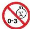
OUR KITS CONTAIN SMALL PARTS
This package contains small parts which, before assembly, present a choking hazard to children under the age of three. Care should be taken during unpacking and assembly to insure that all small parts and plastic bags are accounted for and kept out of the reach of children.
QUESTIONS OR SUPPORT NEEDED?
You can mail us all your questions at: support@infentorides.com
and our team will reply you as soon as possible.
text_image
support@infentorides.com and our team will reply you as soon as possible.MAINTENANCE | INSTRUCTION
- Oil or grease moving parts periodically.
- Check nuts and bolts often and tighten if necessary.
- Any parts showing evidence or wear should be replaced immediately.
- Follow closely the assembly instructions pertaining to the proper adjustments of parts
- Periodically check the brake system for proper function
- Periodically check the steering mechanism for proper function
- Check the air pressure in the tires to be the amount specified in the manual
- Periodically check the bicycle's tooth belt to be sure that it is not too lose which could allow the chain to slip off the sprockets.
RECOMMENDED TOOLS

4 x Allen key
3, 4, 5, 6 mm

1 x Tapeline
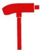
1 x T-handle for Allen key
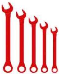
natural_image
Six red wrench-style tools arranged in descending order (no text or symbols)5 x Wrench 10, 13, 14, 15, 19 mm

1
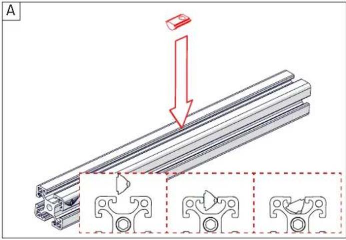
First, get all required materials stated here and then follow the instructions.
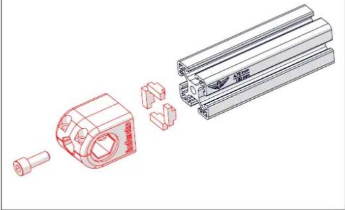
Bolt M8x20


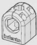
T-Positioning block


Profi le nut short

The Ground Truth image displays a single, solid horizontal line. According to Rule 2 (UNDERSCORE & LINE RULES), this is a stylistic or background line, not a placeholder underscore. Therefore, the OCR result must ignore it and output nothing or only meaningful text. The provided OCR content is "____", which consists of four underscores. This is an incorrect interpretation of the line as a placeholder, violating the rule that stylistic lines must be ignored. The OCR has hallucinated underscores where none should exist based on the GT's visual context. Hence, the OCR result is inconsistent with the Ground Truth.
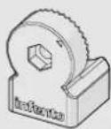
Multi angle joint

1
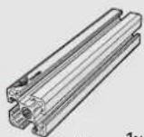
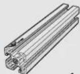
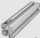
Profi le 14.17inch | 360mm
ride BOOSTER
text_image
A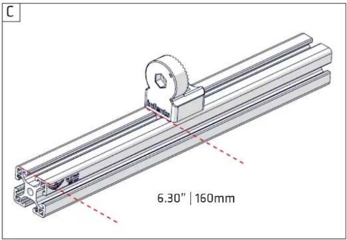
text_image
C 6.30" | 160mmTighten the bolts with full force. Ensure that you hold the long side of the Allen key in your hand as this enables you to exert greater force.
natural_image
Technical illustration of a mechanical assembly with a bracket and mounting bracket, showing exploded view (no text or symbols)When tightening the bolt always check whether the profi le nut remains perfectly straight in the slot. If this becomes crooked, you can push against the side of the profi le bolt with the Allen key to correct this.
text_image
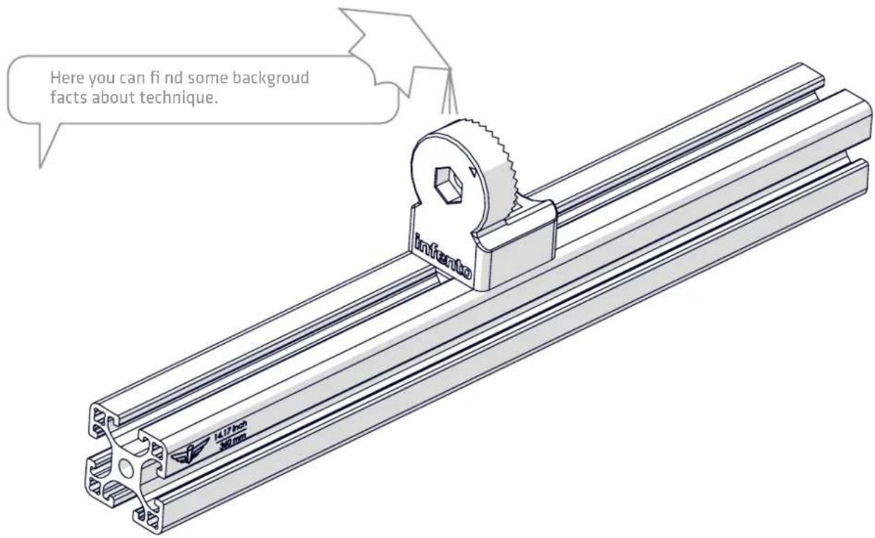
Here you can find some background facts about technique. Infanto 14.17 inch 30 mmTOP 3 REQUIREMENTS MAKING A GREAT INFENTO EXPERIENCE:

1
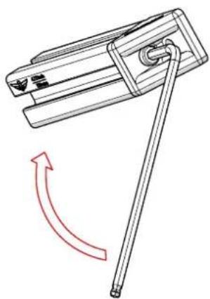
Tighten bolts with full force (15Nm) to prevent them from coming loose.
natural_image
Diagram of a mechanical clamp or tool with a red curved arrow indicating rotational motion (no text or symbols present)
2
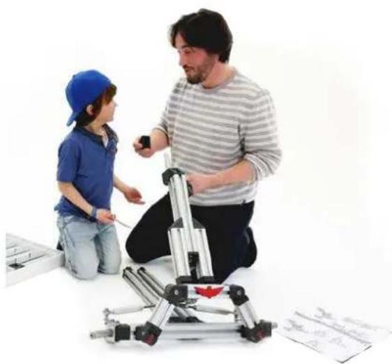
Constructing and playing always under supervision of an adult.
natural_image
Two people interacting with a mechanical device on a white surface (no visible text or symbols)
3
Check frequently if all parts are still firmly tightened and function properly.

natural_image
Child in blue cap and shirt working on a keyboard, with adult hands adjusting the keyboard (no visible text or symbols)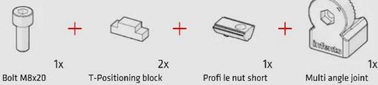
text_image
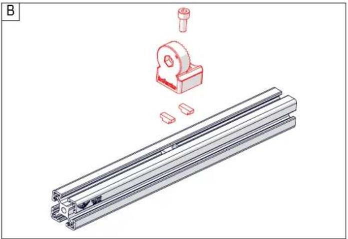
Bolt M8x20 1x T-Positioning block 2x Profi le nut short 1x Multi angle joint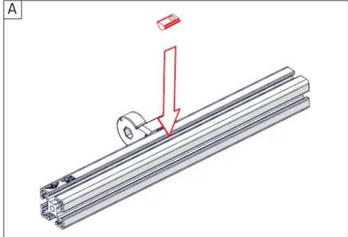
natural_image
Mechanical assembly diagram showing a metal bracket with a red arrow indicating a downward force or adjustment, no text or symbols present.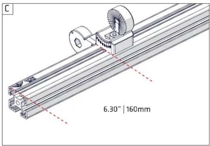
text_image
C 6.30" | 160mm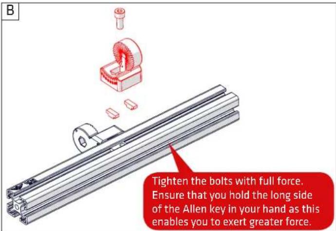
text_image
B Tighten the bolts with full force. Ensure that you hold the long side of the Allen key in your hand as this enables you to exert greater force.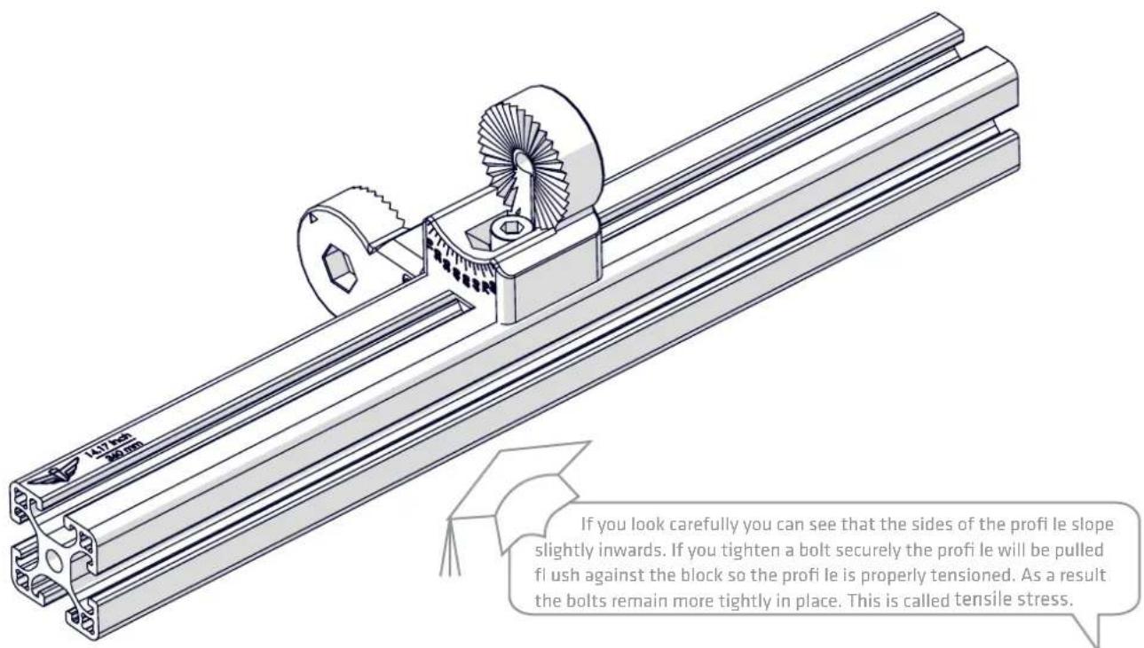
text_image
197.45 30mm If you look carefully you can see that the sides of the profi le slope slightly inwards. If you tighten a bolt securely the profi le will be pulled flush against the block so the profi le is properly tensioned. As a result the bolts remain more tightly in place. This is called tensile stress.
3
ride BOOSTER

m = 311

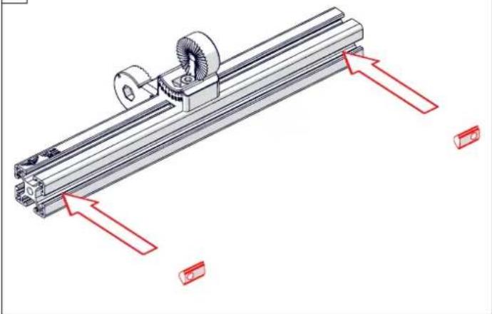
Profi le nut short
Positioning block
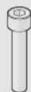
Bolt M8x40

Protect cap
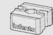
T-joint
2x
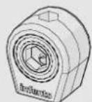
Bearing block 40x40_Hexa 19
2x
A
natural_image
Technical illustration of a mechanical assembly with red arrows indicating motion direction (no text or symbols)C
natural_image
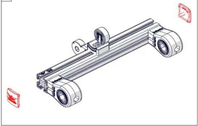
Technical line drawing of a mechanical device with wheels and mounting brackets (no text or symbols)Use the Allen key handle so you can tighten the bolt well.
B
natural_image
Exploded view diagram of a mechanical assembly with red component blocks and shafts (no text or labels)
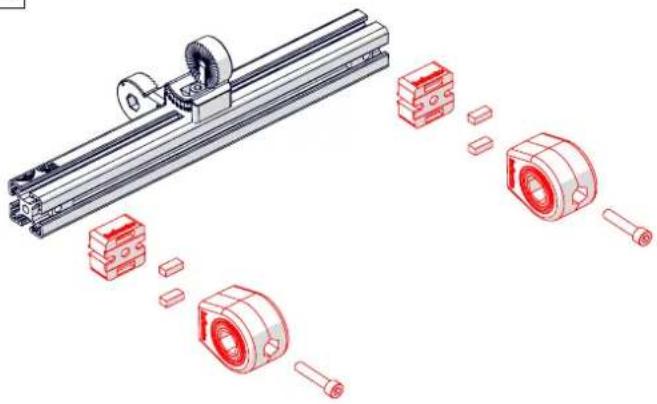
All Infento block bearings have two bearings with a spacer in between. This ensures that you can e.g. put a bolt or a washer tightly against the block bearing without it breaking. A bearing cannot withstand lateral pressure very well; this is because a bearing consists of two washers with small balls locked in between.
natural_image
Technical line drawing of a mechanical device with labeled components (no text or symbols beyond branding)
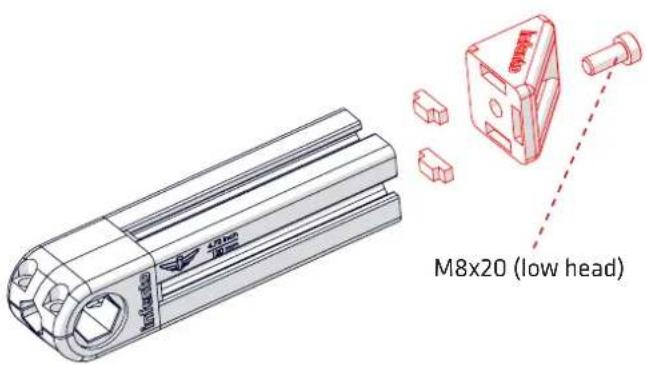
Bolt M8x20 1x (low head)

Bolt M8x20

T-Positioning block
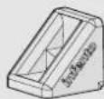
L-joint
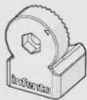
Multi angle joint
14.17inch|360mm
A
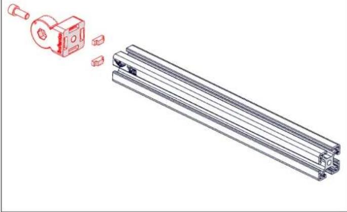
natural_image
Technical line drawing of a mechanical assembly with exploded view and assembled view (no text or symbols)B
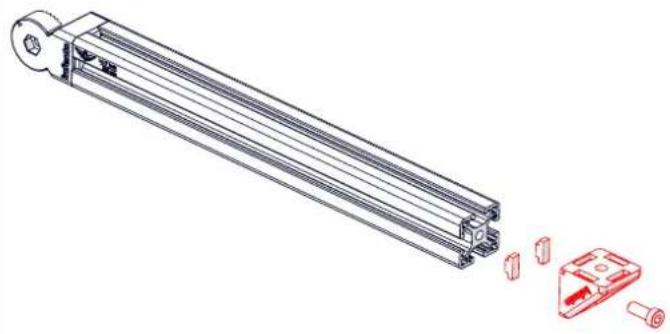
natural_image
Technical line drawing of a mechanical assembly with exploded view and red component detail (no text or symbols)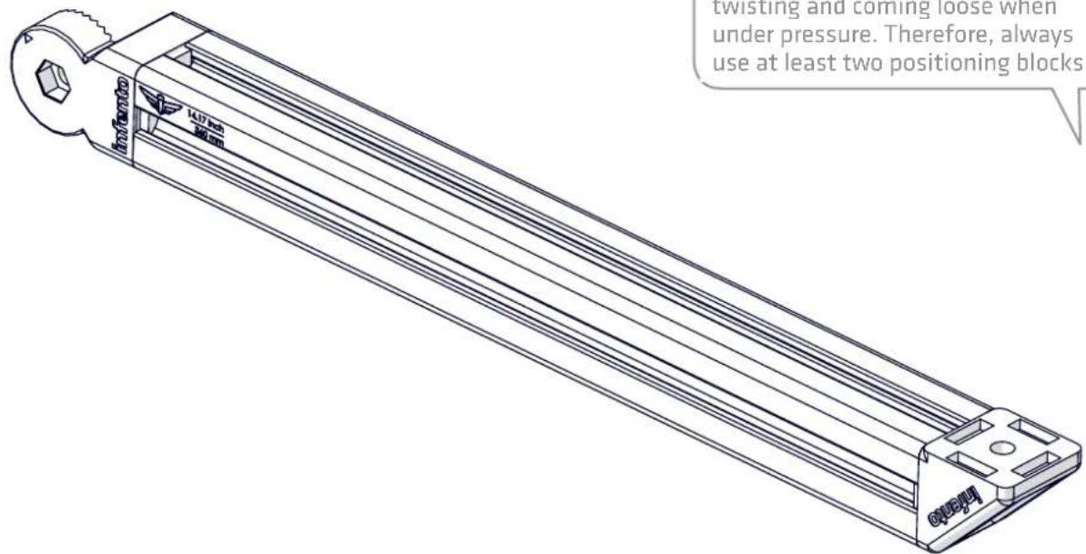
text_image
twisting and coming loose when under pressure. Therefore, always use at least two positioning blocks
5
ride BOOSTER

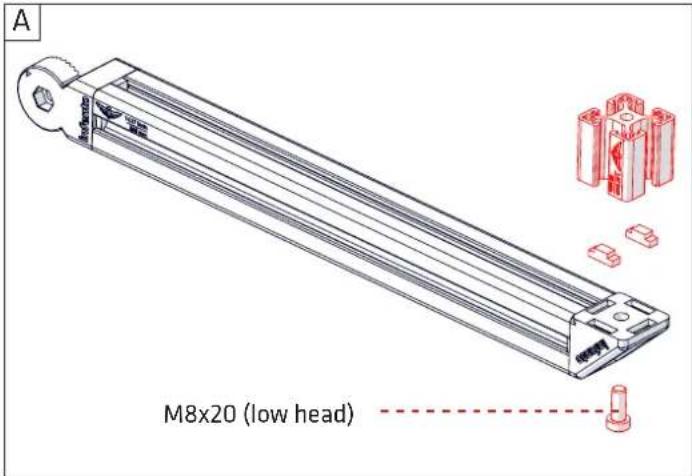
Bolt M8x20 1x (low head)

T-Positioning block

1x
Profi le nut short

Bolt M8x20
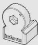
Multi angle joint
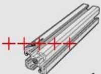
Profi le
1.57inch | 40mm
text_image
A M8x20 (low head)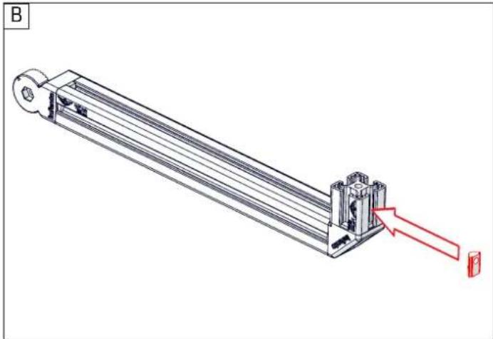
natural_image
Technical line drawing of a mechanical assembly with a red arrow pointing to a component (no text or symbols present)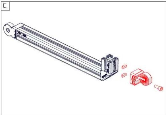
natural_image
Technical illustration of a mechanical assembly with exploded view and red circular components (no text or symbols)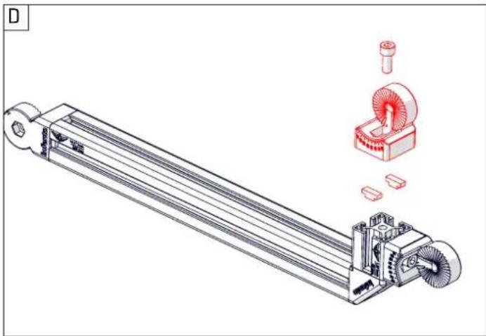
natural_image
Technical illustration of a mechanical assembly with exploded view and 3D model inset (no text or symbols)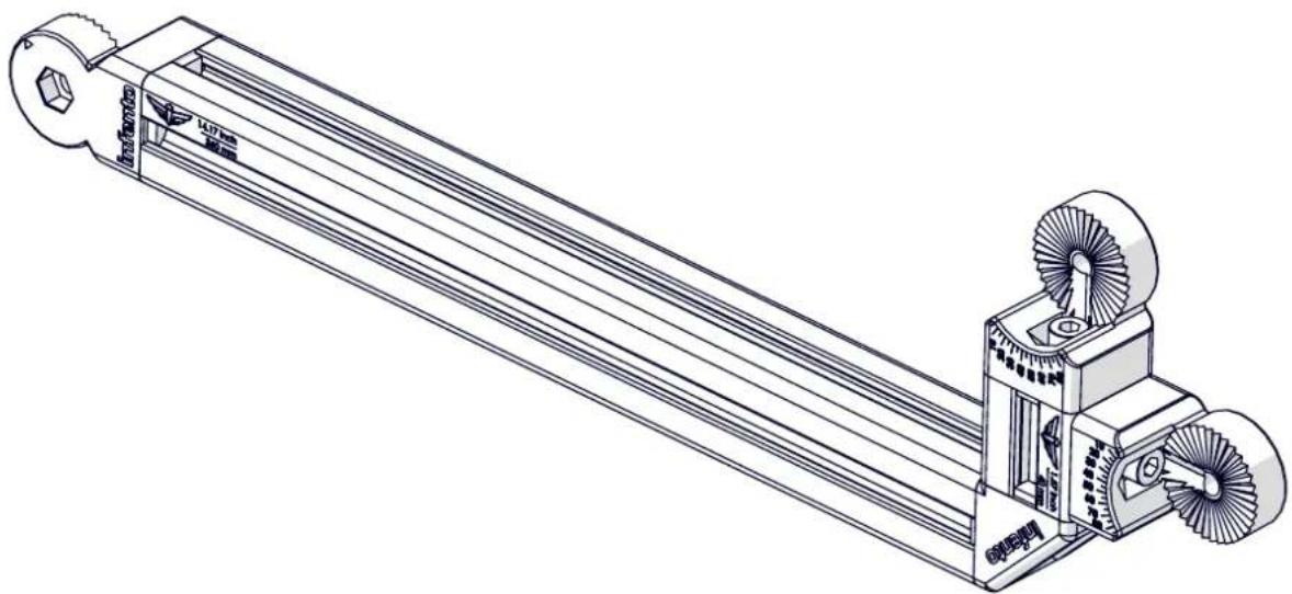
natural_image
Technical line drawing of a mechanical assembly with no visible text or symbols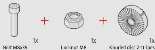
text_image
Bolt M8x35 + Locknut M8 + Knurled disc 2 stripes 1x 1x 1x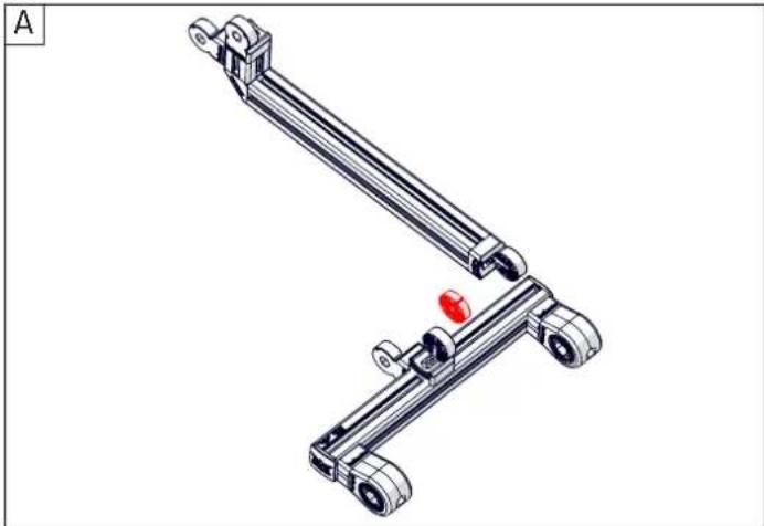
natural_image
Technical illustration of a mechanical linkage system with two articulated arms and a red accent (no text or symbols)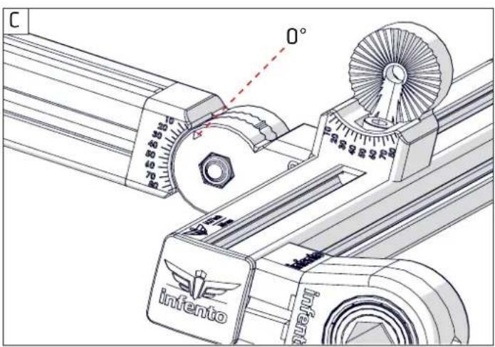
text_image
C 70° 10 20 30 40 50 60 70° 80° 90° 100° 110° 120° 130° 140° infento infento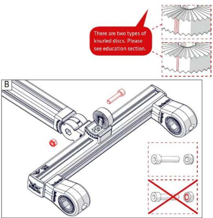
text_image
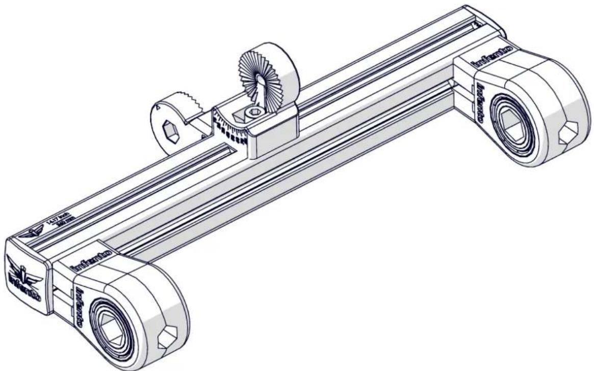
There are two types of knurled discs. Please see education section. B
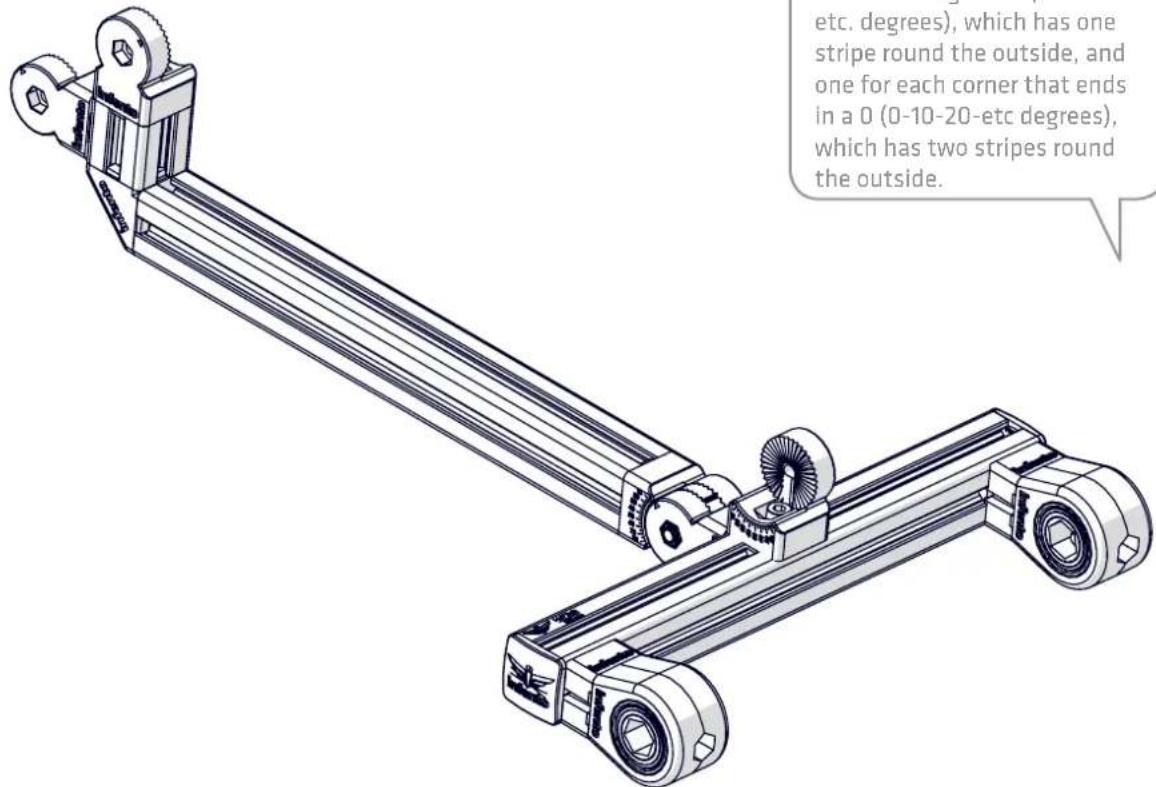
There are two different knurled discs. One for each corner ending in a 5 (5-15-25-etc. degrees), which has one stripe round the outside, and one for each corner that ends in a 0 (0-10-20-etc degrees), which has two stripes round the outside.
text_image
etc. degrees), which has one stripe round the outside, and one for each corner that ends in a 0 (0-10-20-etc degrees), which has two stripes round the outside.
natural_image
Diagram of a car wheel with red arrows indicating rotational motion, no text or symbols present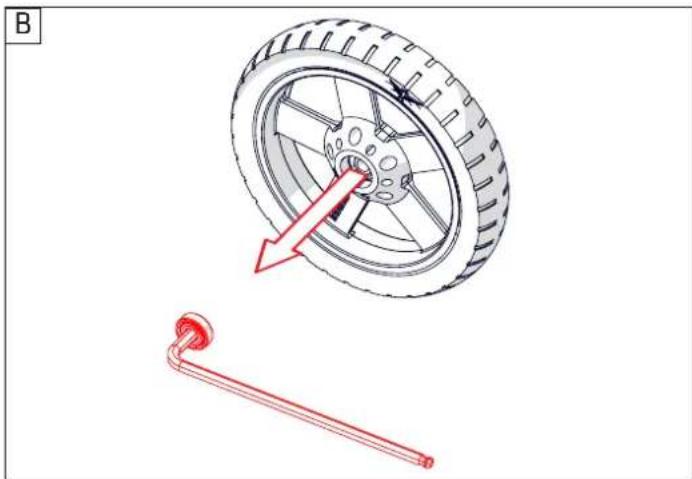
natural_image
Diagram showing a car tire and a red-handled tool, no text or symbols present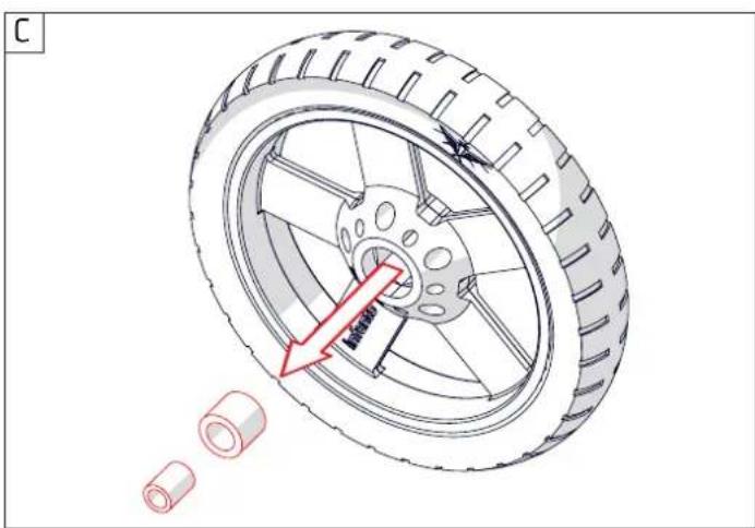
natural_image
Technical illustration of a tire with a red arrow indicating fastening direction, alongside two small cylindrical components (no text or symbols)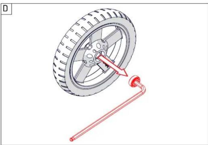
natural_image
Diagram showing a car tire and a red tool inserted into a spring, with no visible text or symbols.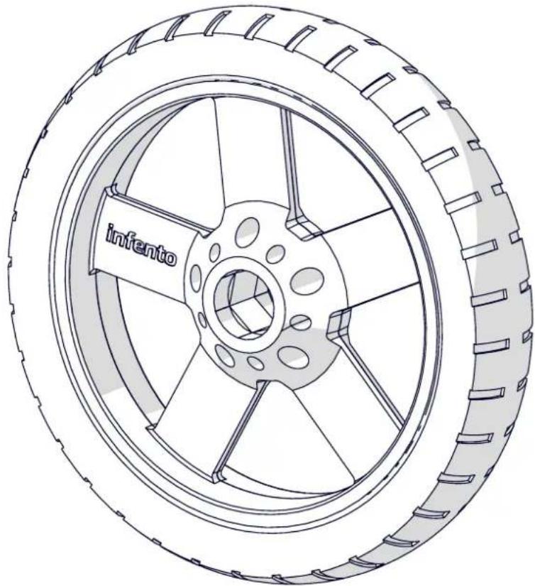
natural_image
Technical line drawing of a tire with labeled 'infento' component (no other text or symbols)


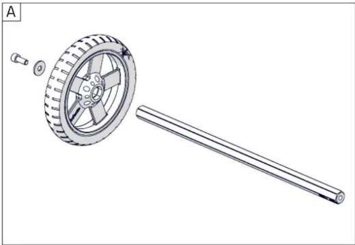
natural_image
Technical illustration of a wheel and rod assembly (no text or symbols)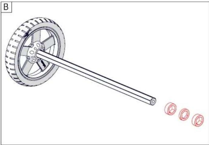
natural_image
Technical illustration of a wheeled cart with a long shaft and three red circular components nearby (no text or symbols)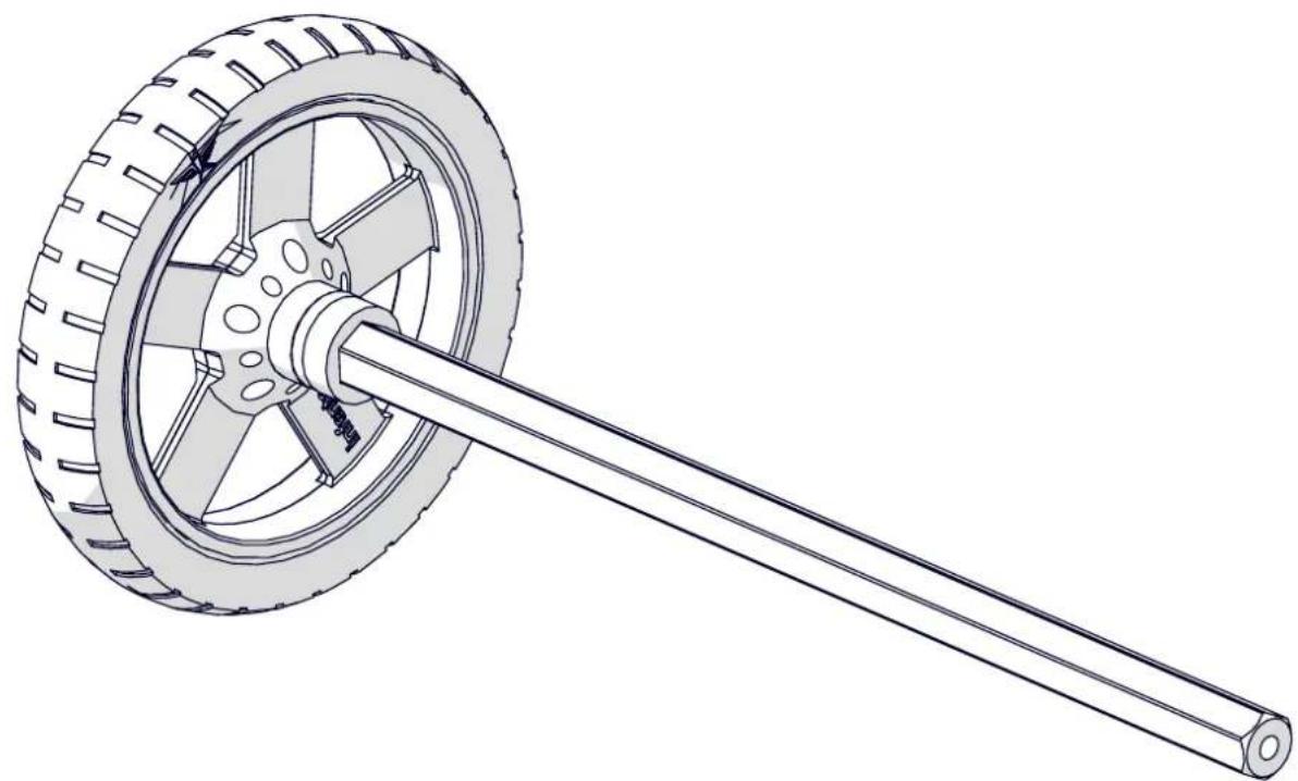
natural_image
Technical line drawing of a mechanical component with a wheel and shaft (no text or symbols)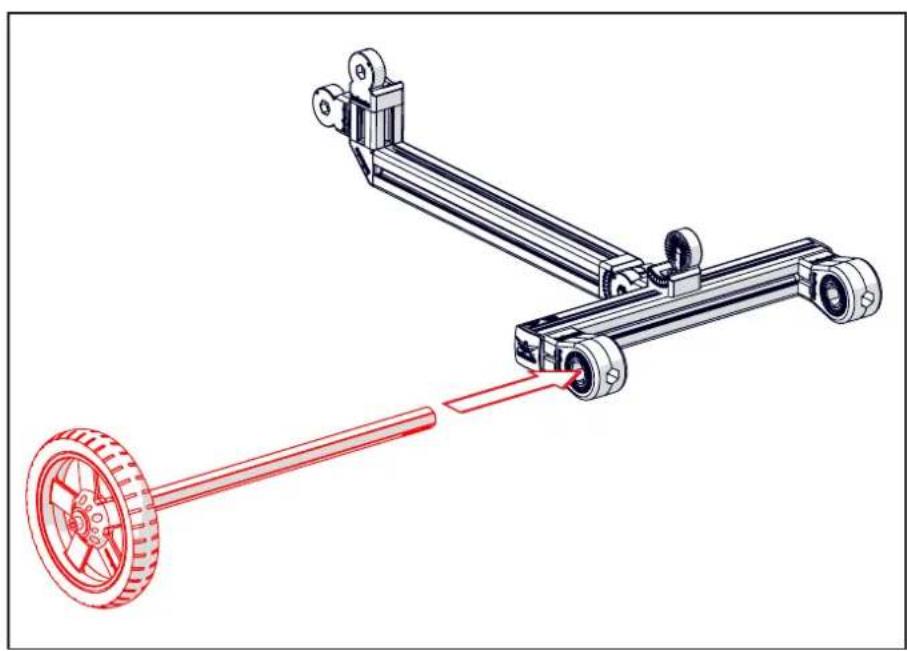
natural_image
Technical illustration of a mechanical linkage system with a red-handled wheel and a blue-handled lever (no text or symbols)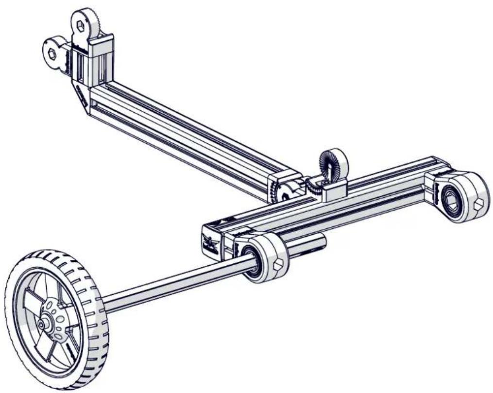
natural_image
Technical line drawing of a mechanical linkage system with two wheels and a shaft (no text or symbols)A
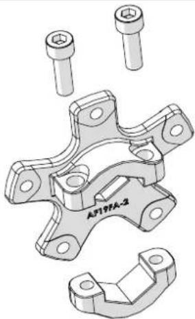
natural_image
Technical drawing of a mechanical bracket assembly with multiple cylindrical components (no text or symbols visible)C
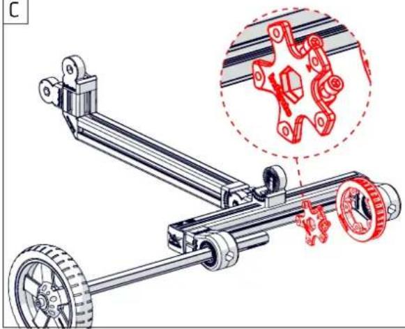
natural_image
Mechanical assembly diagram showing a vehicle chassis with wheels and a magnified inset of a mechanical component (no text or symbols)B
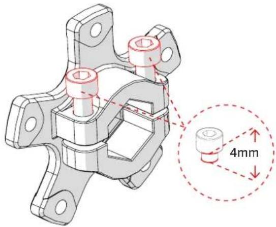
text_image
4mm
natural_image
Technical line drawing of a mechanical linkage system with two wheels and gears (no text or symbols)

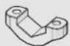

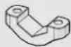
Bolt M6x16
2x
Clamping part 1x holes with M6 thread
Clamping part holes without
1x
text_image
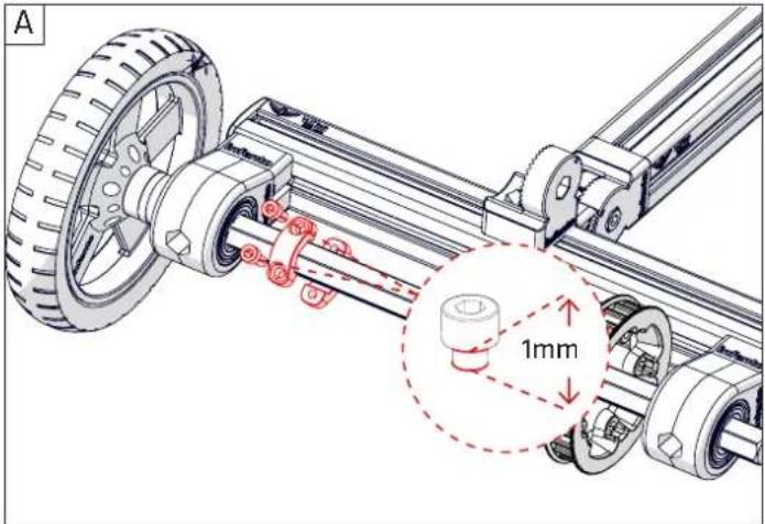
A 1mm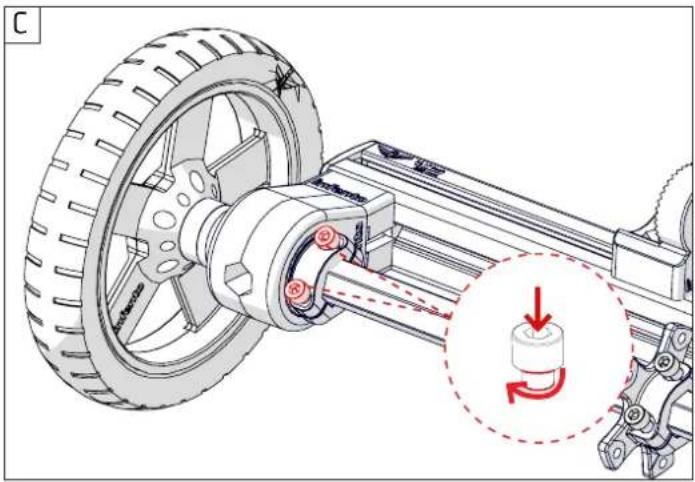
natural_image
Mechanical assembly diagram showing a wheel connected to a shaft with a gear mechanism, no text or symbols present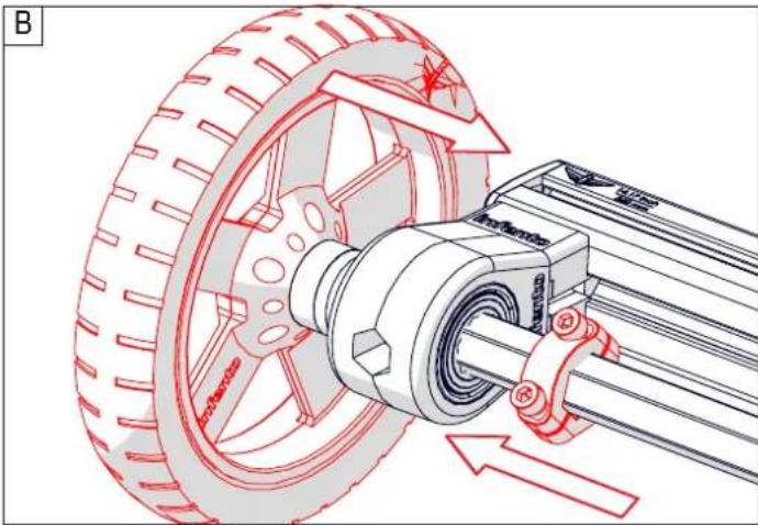
natural_image
Technical illustration of a mechanical assembly with a wheel, shaft, and gear (no text or symbols)
natural_image
Technical line drawing of a mechanical vehicle with wheels and suspension components (no text or symbols)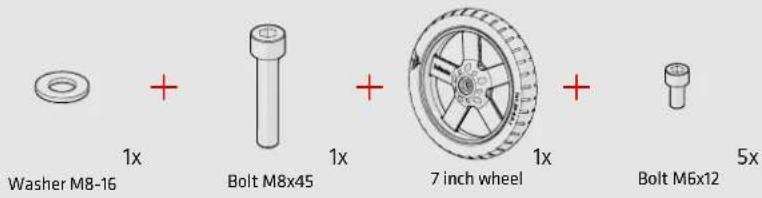
text_image
Washer M8-16 + 1x Bolt M8x45 + 1x 7 inch wheel + 1x Bolt M6x12 5x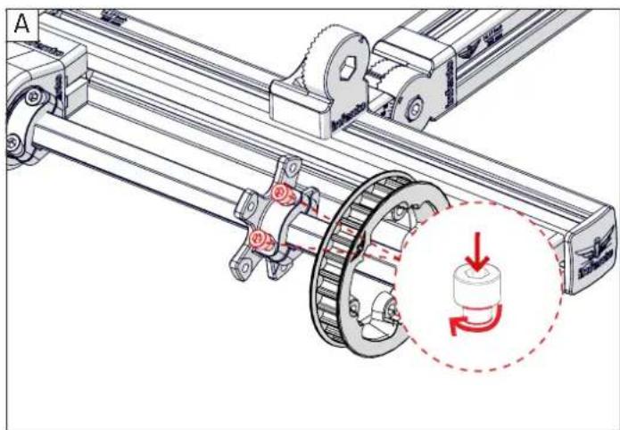
natural_image
Mechanical assembly diagram showing a rotating gear mechanism with a red dashed circle highlighting a rotational component (no text or symbols present)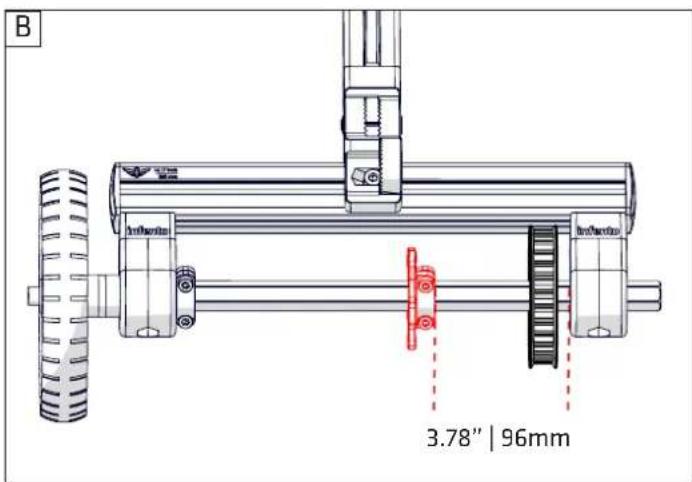
text_image
B 3.78" | 96mm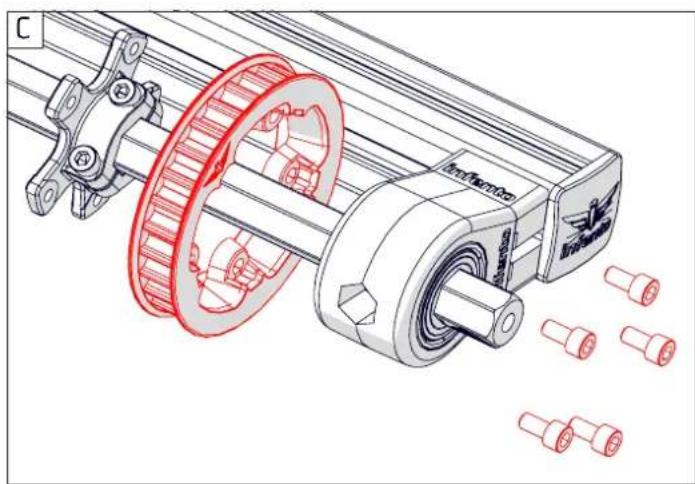
natural_image
Technical illustration of a mechanical assembly with gears and shafts, showing no text or symbols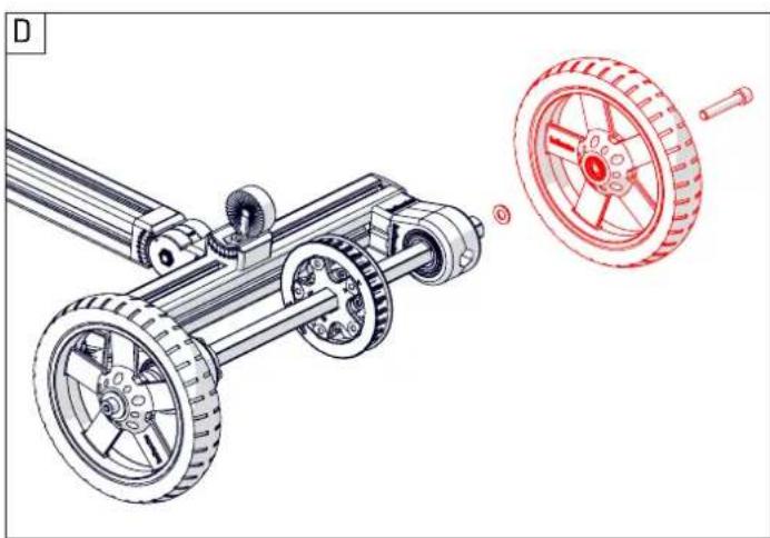
natural_image
Mechanical assembly diagram showing a motor with wheels and a separate wheel component (no text or symbols)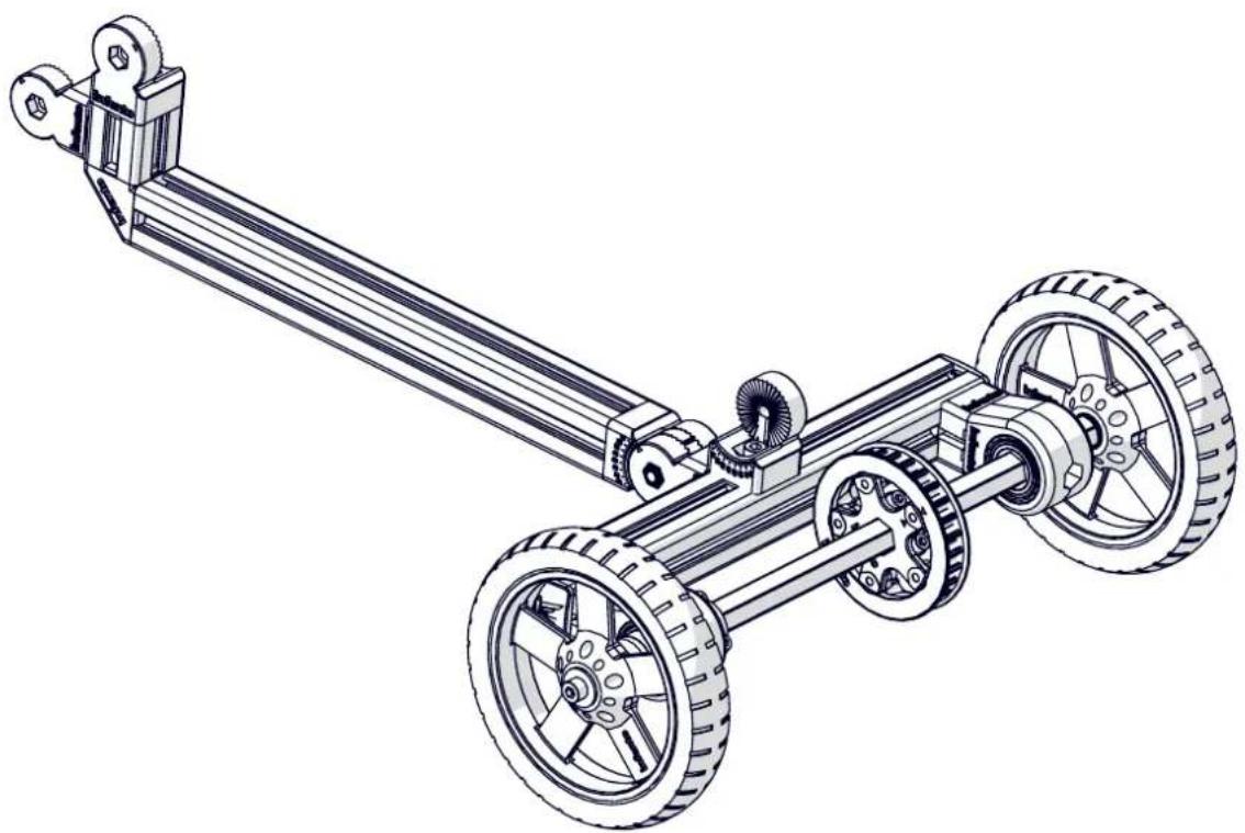
natural_image
Technical line drawing of a mechanical vehicle with two wheels and a long shaft (no text or symbols)

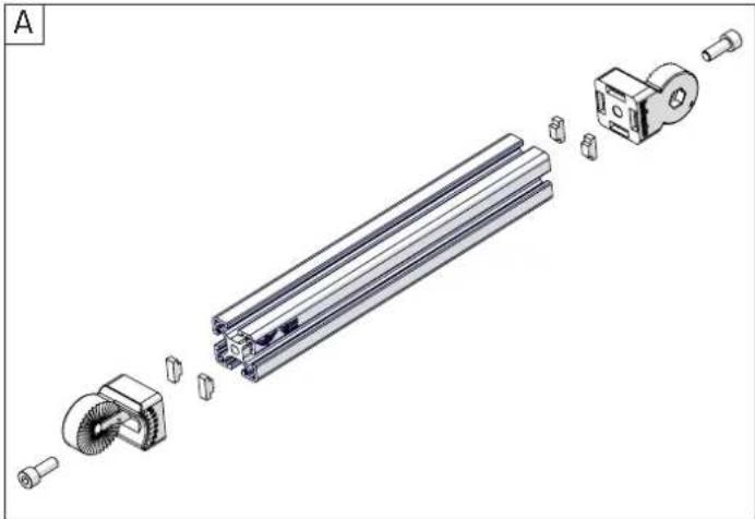
1x Profi le nut short
3x Bolt M8x20

6 T-Positioning block
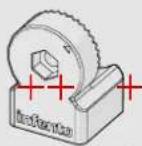
Multi angle joint
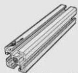
Profi le 1x
11.02inch | 280mm
natural_image
Exploded view diagram of a mechanical assembly showing exploded view of components like gears and parts (no text or labels)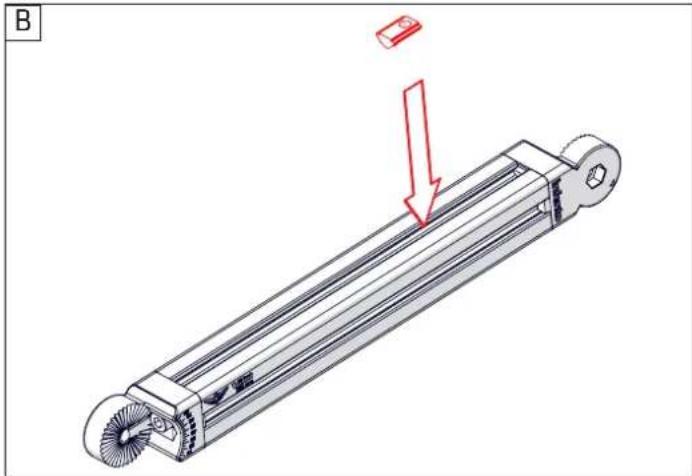
natural_image
Technical illustration of a mechanical component with a red arrow indicating a downward motion, labeled 'B' in the corner (no text or symbols on the diagram itself)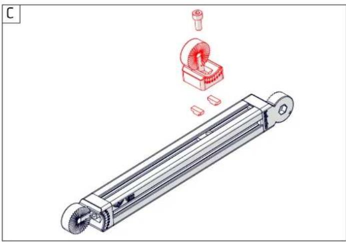
natural_image
Technical illustration of a mechanical component with exploded view showing internal parts and assembly (no text or symbols)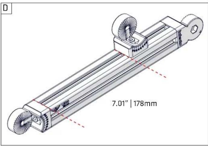
text_image
D 7.01" | 178mm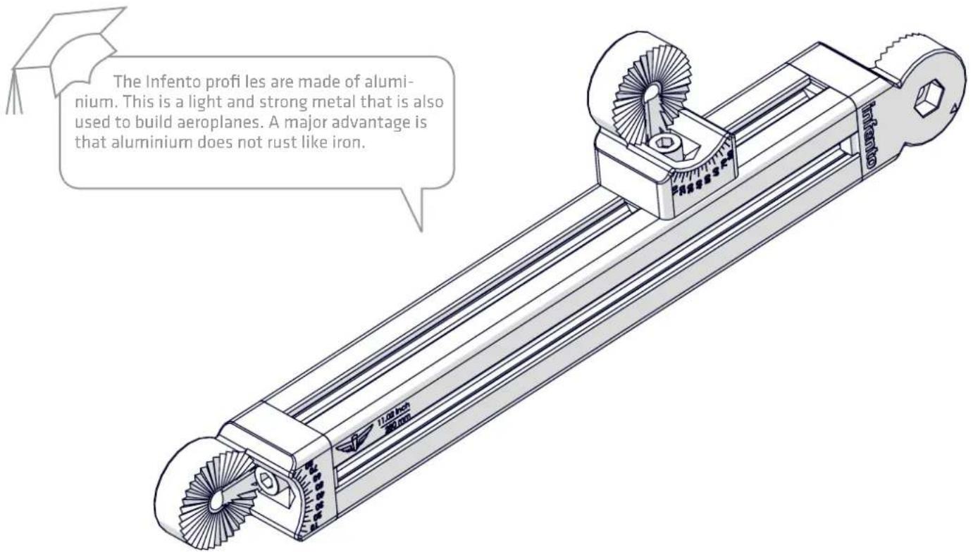
text_image
The Infento profi les are made of aluminium. This is a light and strong metal that is also used to build aeroplanes. A major advantage is that aluminium does not rust like iron.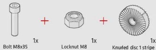
text_image
Bolt M8x35 + Locknut M8 + Knurled disc 1 stripe 1x 1x 1x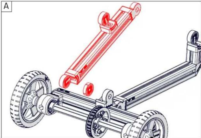
natural_image
Mechanical assembly diagram showing a vehicle chassis with wheels and a red mechanical component (no text or symbols)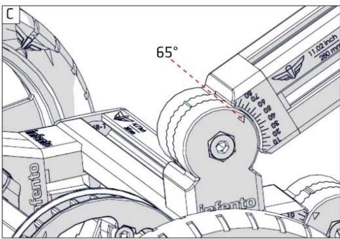
text_image
C 65° 11.02 inch 280 mm Infanto Infanto
natural_image
Technical illustration of a mechanical assembly with labeled components (no readable text or symbols)
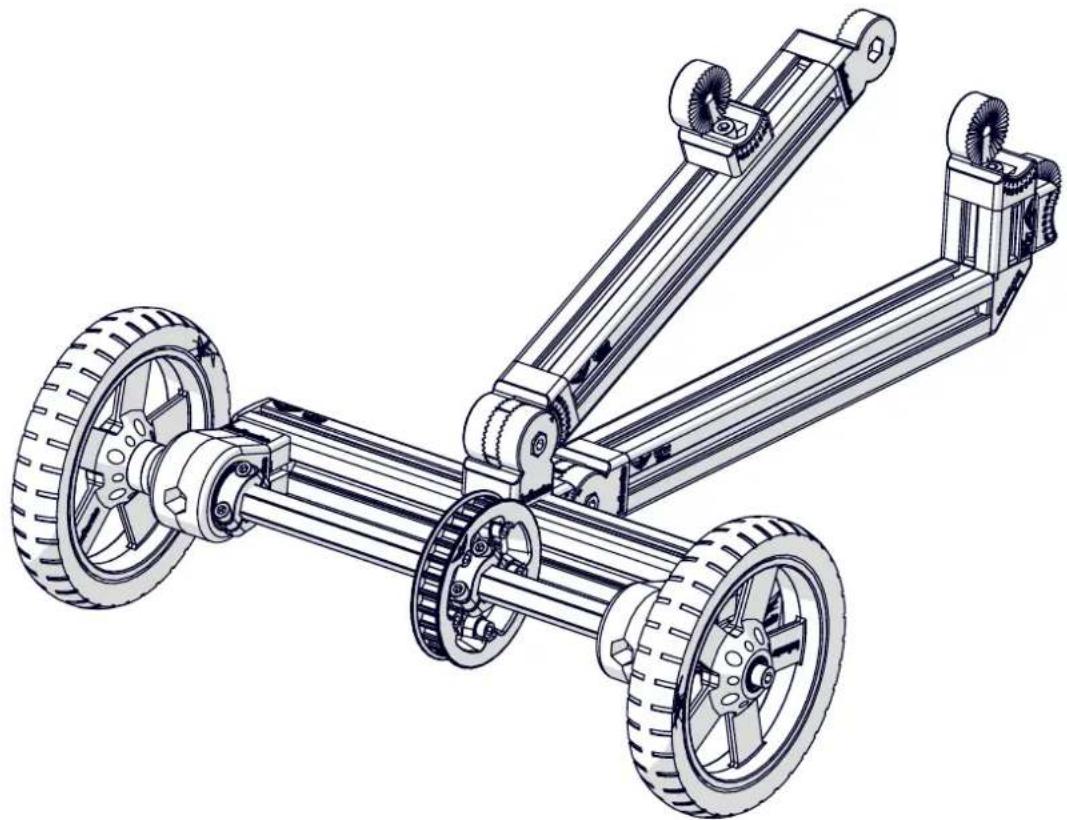
natural_image
Technical line drawing of a three-wheeled vehicle chassis with wheels and suspension components (no text or symbols)
+

+

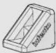
m = 311

Profi le 1x
3.15inch | 80mm
L-joint
6x T-Positioning block
Profi le nut short
Bolt M8x20 3x (low head)
A
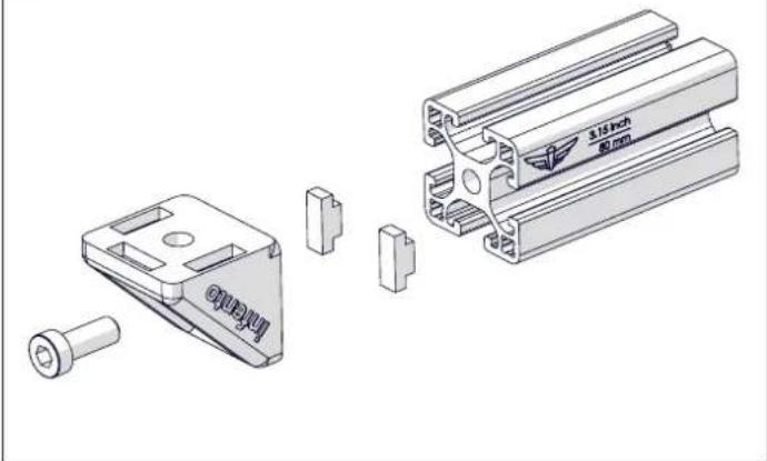
natural_image
Technical illustration of a mechanical assembly with exploded view and part views (no text or symbols)B
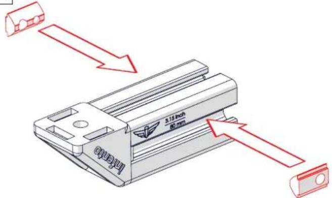
text_image
3.15 inch 80 mmC
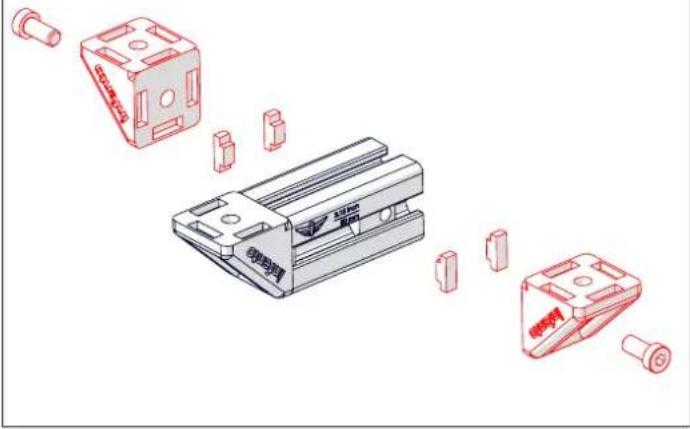
natural_image
Exploded view diagram of a mechanical component with red outline and exploded view (no text or symbols)
text_image
the 3.15 inch 80 mm intero
Locknut M8
m = 311
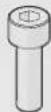
Bolt M8x25
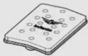
Ducktail board 1x extension + foam

Bolt M8x20

T-Positioning block
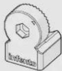
Multi angle joint
A
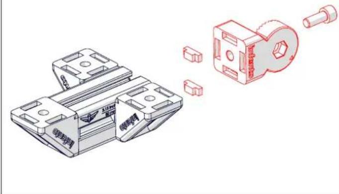
natural_image
Technical illustration of a mechanical clamp assembly with a close-up view of its internal components (no text or symbols present)C
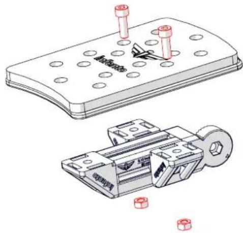
natural_image
Technical illustration of a mechanical component with bolt holes and exploded view (no text or symbols)B
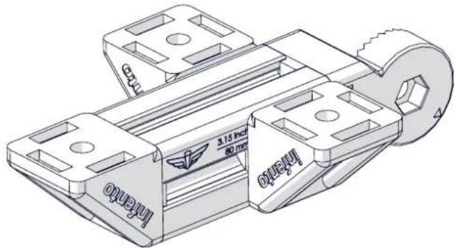
text_image
3.12 inch 80 mm Inamo Inamo
The Infento profi les are made of aluminium. This is a light and strong metal that is also used to build aeroplanes. A major advantage is that aluminium does not rust like iron.
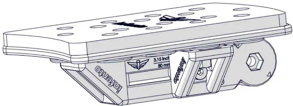
text_image
Interneo 3.15 inch 80 mm Interneo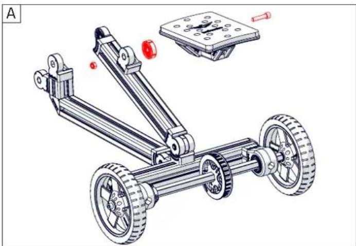
natural_image
Technical illustration of a mechanical vehicle with wheels and a mounted platform (no text or symbols)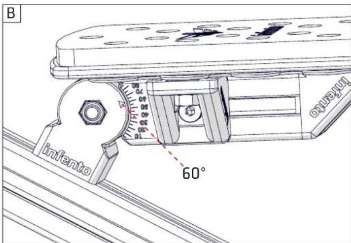
text_image
B infento 60° ouregunt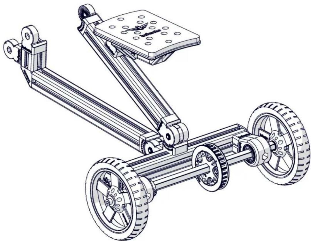
natural_image
Technical line drawing of a mechanical vehicle with wheels and a flat plate (no text or symbols)
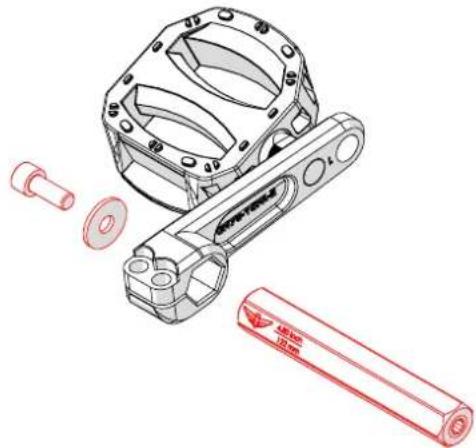
Bolt M8x20

1x Washer M8-24
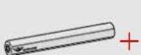
Axle
4.8inch | 122mm
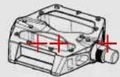
Pedal left
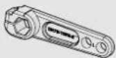
1x
Crank small left
A
natural_image
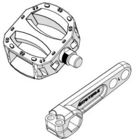
Technical line drawing of two mechanical components: a circular housing with internal cavities and a rectangular tool with circular holes (no text or symbols)C
text_image
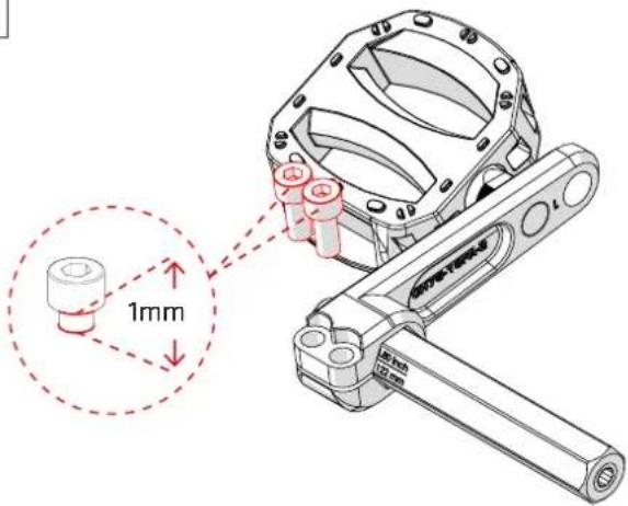
1mm 1mm 12mmB
natural_image
Technical illustration of a mechanical assembly with exploded view and red outline (no text or symbols)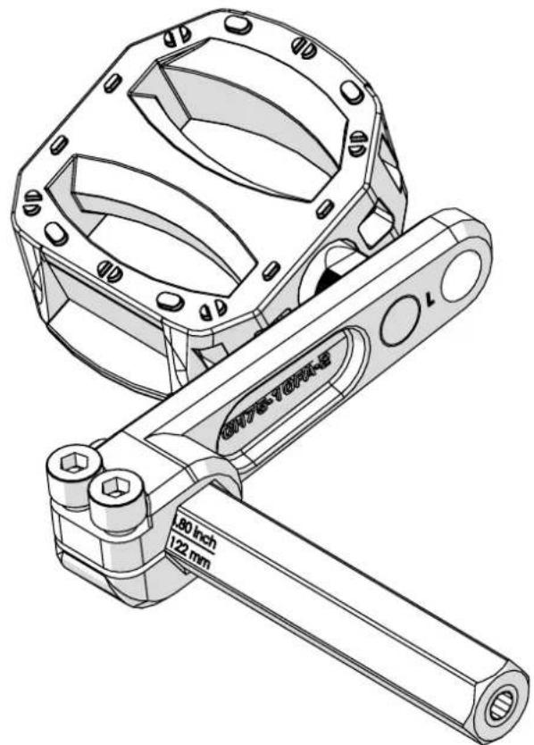
natural_image
Technical line drawing of a mechanical clamp or bracket assembly (no text or symbols)
natural_image
Technical illustration of a mechanical device with red arrows indicating flow or movement, no visible text or symbols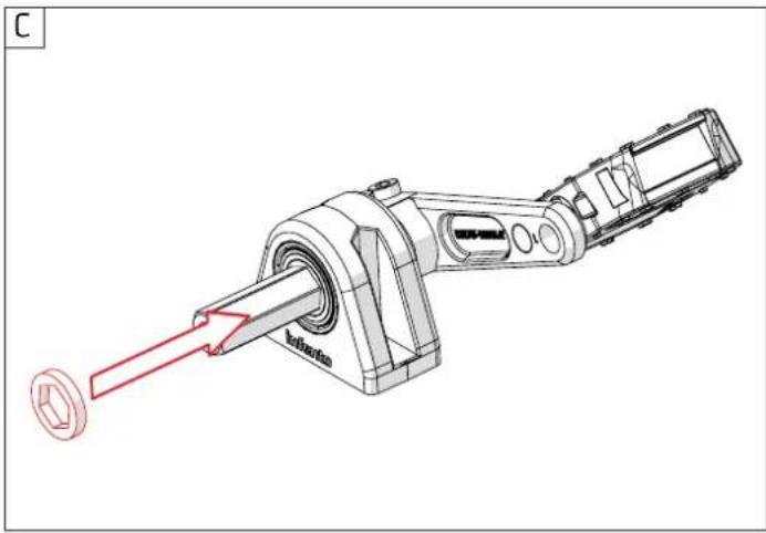
natural_image
Technical line drawing of a mechanical device with a red arrow pointing to a component labeled 'batharion', no readable text or symbols present.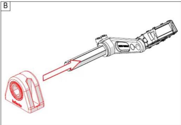
natural_image
Technical illustration of a mechanical assembly with a red arrow indicating direction, showing a component with no visible text or symbols.
natural_image
Technical line drawing of a mechanical assembly with labeled components (Infento and G70-1002), no readable text or symbols beyond branding
Spacer 1x
0.2inch | 5 mm

Bolt M6x12

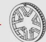
Toothed belt pulley 45T

Bolt M6x20

This image contains no text. The horizontal line is a stylistic or background element and must be ignored according to the rules.
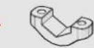
Clamping part 1x holes with M6 thread

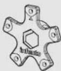
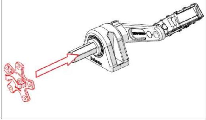
Axle fl ange
1x
A
natural_image
Technical illustration of a mechanical assembly with a red arrow indicating motion or force direction (no text or symbols present)B
text_image
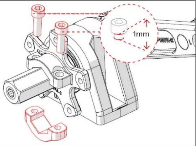
1mm A-2C
natural_image
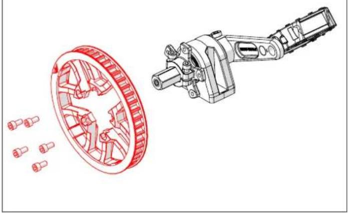
Technical illustration of a mechanical assembly with a wheel and shaft component (no text or symbols)D
natural_image
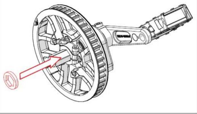
Mechanical assembly diagram showing a wheel and shaft assembly with a red arrow pointing to a component (no text or labels present)
natural_image
Technical line drawing of a mechanical gear assembly with visible gears and shafts (no text or symbols)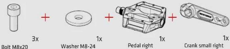
text_image
Bolt M8x20 3x Washer M8-24 1x Pedal right 1x Crank small right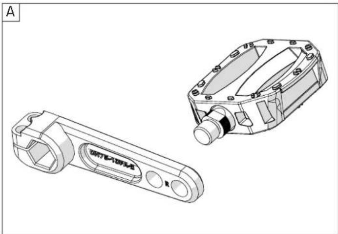
natural_image
Technical line drawing of two mechanical components (no text or symbols)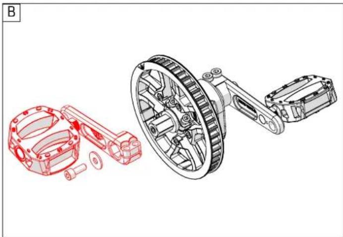
natural_image
Technical illustration of a mechanical assembly with exploded and assembled views (no text or symbols)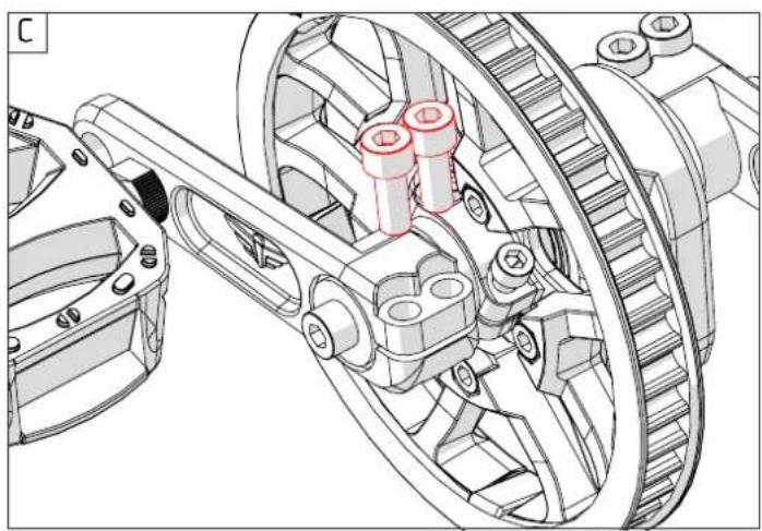
natural_image
Technical illustration of a mechanical gear assembly with no visible text or symbols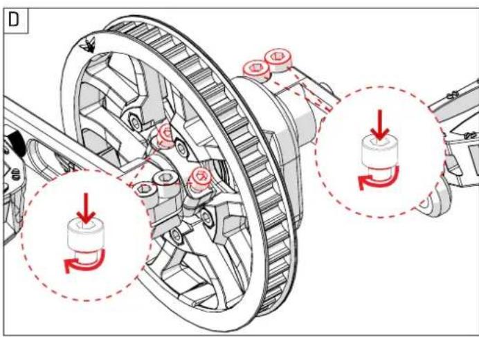
text_image
Technical diagram showing mechanical assembly with gear and pulley components, annotated with red arrows indicating rotational direction.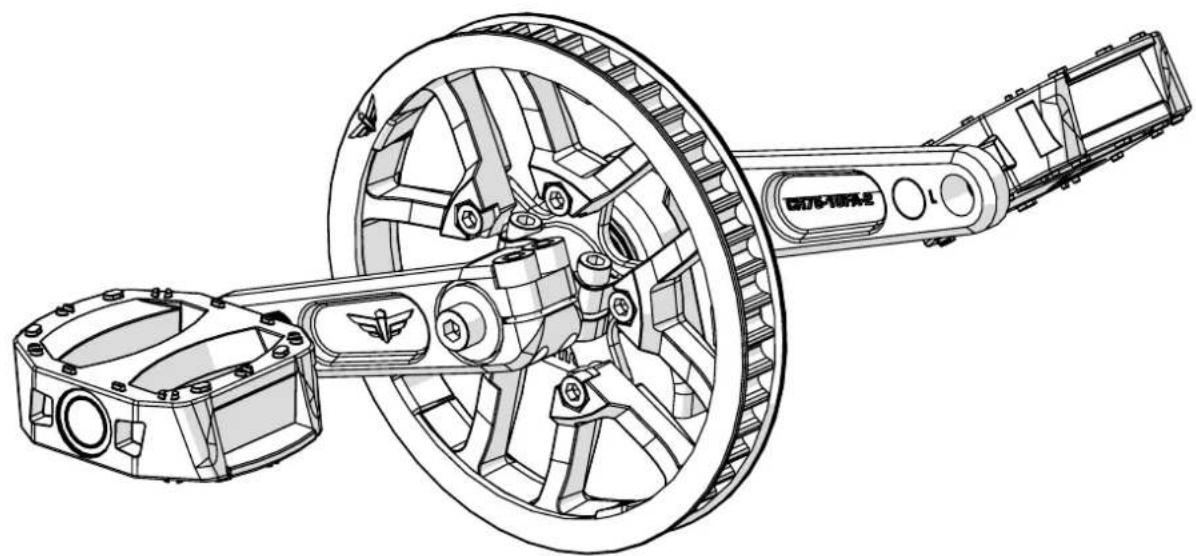
natural_image
Technical line drawing of a mechanical assembly with gears and shafts (no text or symbols)
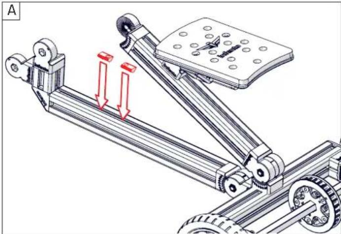
Bolt M8x20


T-Positioning block
2x
Profi le nut short
2x
natural_image
Mechanical linkage system diagram showing motion arrows and components (no text or labels)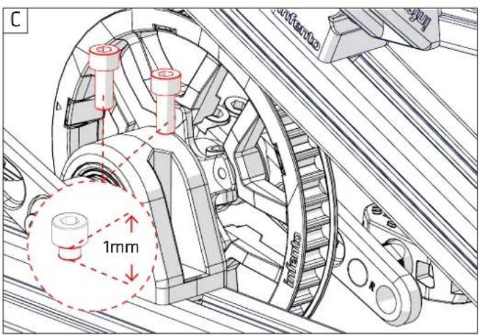
text_image
C 1mm
natural_image
Mechanical linkage system diagram showing motor, pulley, and conveyor components (no text or labels)
natural_image
Technical line drawing of a multi-wheeled vehicle chassis with wheels and a brake plate (no text or symbols)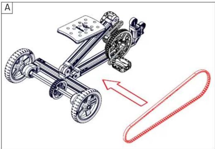
natural_image
Mechanical assembly diagram showing a multi-wheeled vehicle with wheels and gears, accompanied by a red dotted belt indicating motion direction (no text or symbols)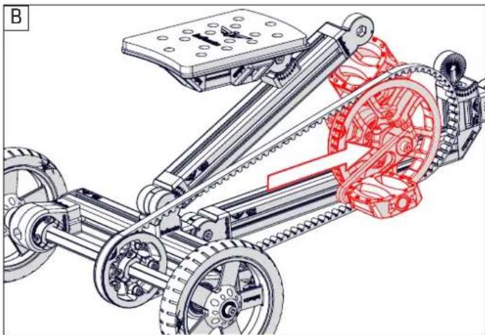
natural_image
Technical illustration of a mechanical assembly with gears and linkages, showing internal components and motion paths (no text or symbols)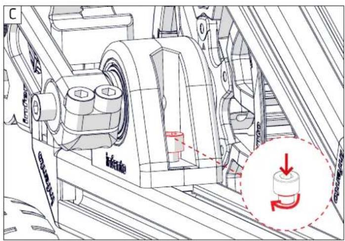
text_image
Technical diagram of a mechanical assembly with labeled components and a red circular annotation indicating rotational motion.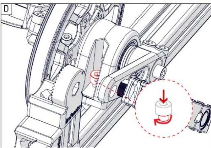
natural_image
Mechanical assembly diagram showing gear and shaft components with a red circular annotation highlighting a rotating component (no text or symbols present)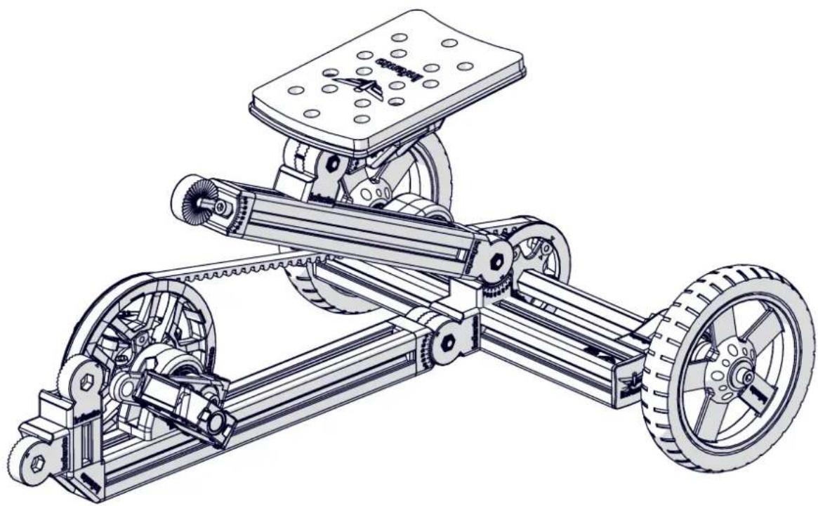
natural_image
Technical line drawing of a mechanical vehicle with wheels, gears, and a mounted platform (no text or symbols)


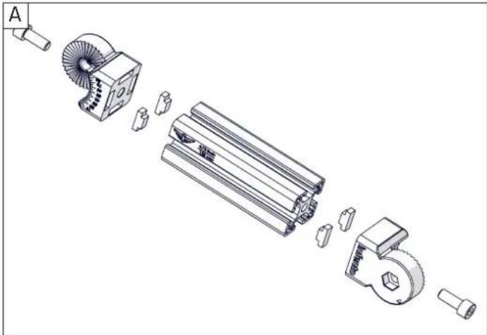
Profi le 1x
4.72inch | 120mm
1x
Profi le nut short
Bolt M8x20
T-Positioning block
6x
Multi angle joint
natural_image
Exploded view diagram of a mechanical assembly showing internal components and parts (no text or labels)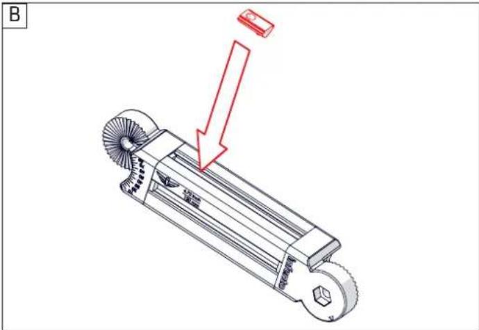
text_image
B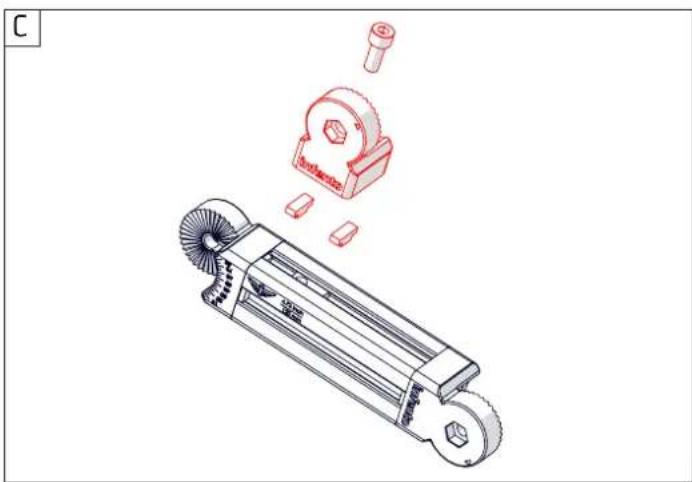
natural_image
Technical illustration of a mechanical tool with exploded view showing internal components (no text or symbols)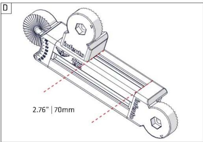
text_image
D Infinito 42mm 70mm 2.76" | 70mm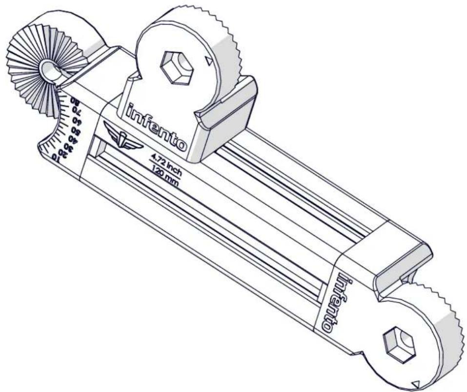
text_image
infento 4.72 inch 120 mm infento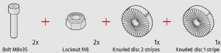
text_image
Bolt MBx35 + Locknut M8 + Knurled disc 2 stripes + Knurled disc 1 stripe 2x 2x 1x 1x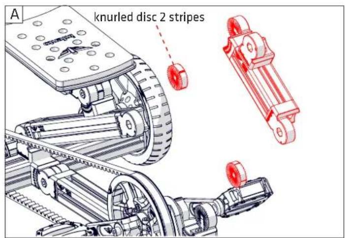
text_image
A knurled disc 2 stripes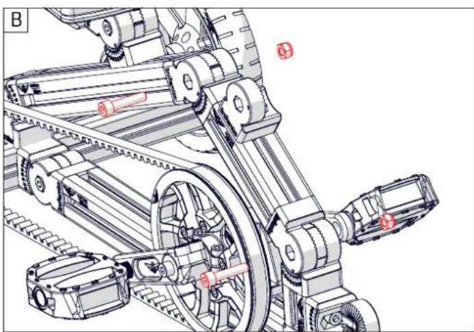
natural_image
Technical line drawing of a mechanical assembly with gears, pulleys, and linkages (no text or symbols)
Most nuts that you use for Infento are self-locking. This means that they cannot vibrate loose. On the inside of the bolt you will see a plastic washer that ensures it cannot turn freely, even if there is no tension on the bolt.
natural_image
Technical line drawing of a mechanical vehicle with wheels and gears (no text or symbols)
+

+

2x
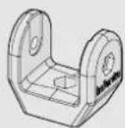
U-Block
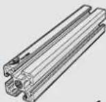
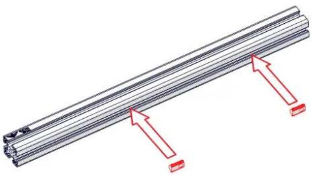
Profi le 1x
20.47inch | 520mm
A
natural_image
Technical illustration of a metal rod with red arrows indicating direction (no text or symbols)C
text_image
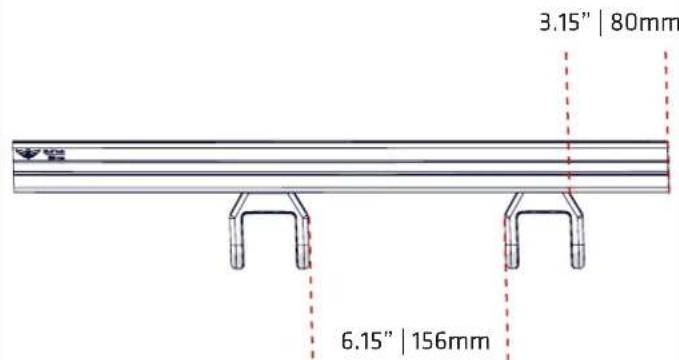
3.15" | 80mm 6.15" | 156mmB

natural_image
Technical illustration of a mechanical assembly with exploded view and component outlines (no text or symbols)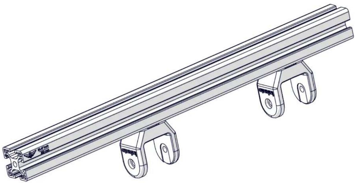
natural_image
Technical line drawing of a multi-level metal rail support structure with mounting feet (no text or symbols)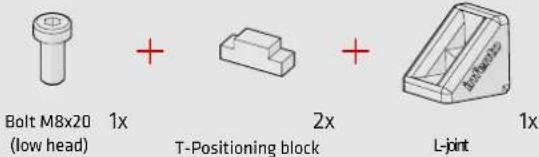
text_image
Bolt M8x20 1x + 2x + L-joint (low head) T-Positioning block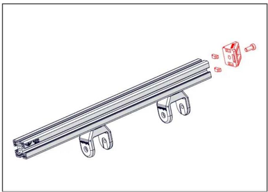
natural_image
Technical illustration of a mechanical rail support system with exploded view and red component detail (no text or symbols)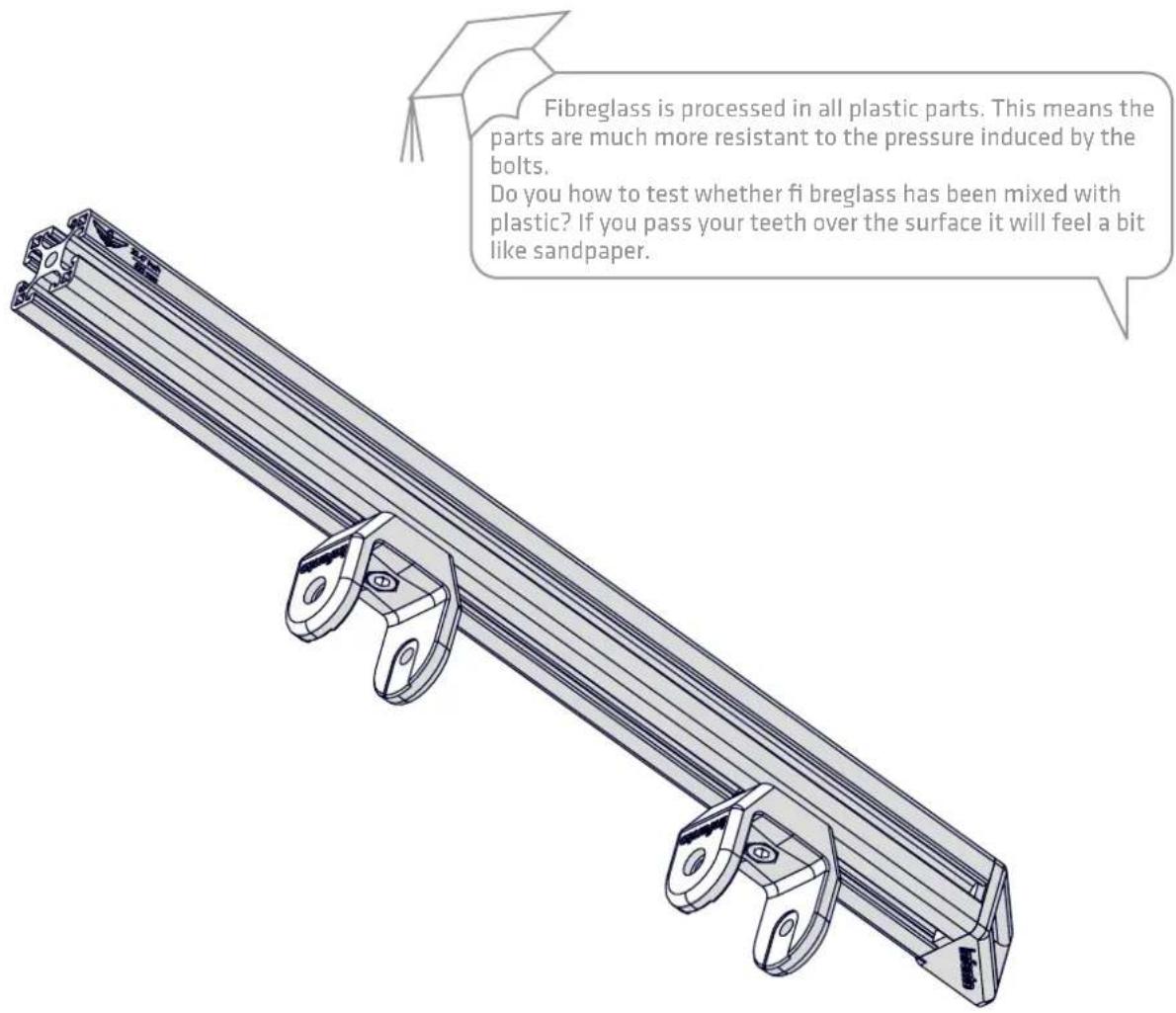
text_image
Fibreglass is processed in all plastic parts. This means the parts are much more resistant to the pressure induced by the bolts. Do you how to test whether fi breglass has been mixed with plastic? If you pass your teeth over the surface it will feel a bit like sandpaper.
Bolt M8x20 1x (low head)

Bolt M8x20

T-Positioning block
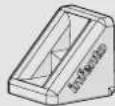
L-joint
-
Axle clamp -
Profi le 12 4.72inch | 120mm
A
natural_image
Technical illustration of a mechanical assembly with exploded view and 3D model views (no text or symbols)B
text_image
M8x20 (low head)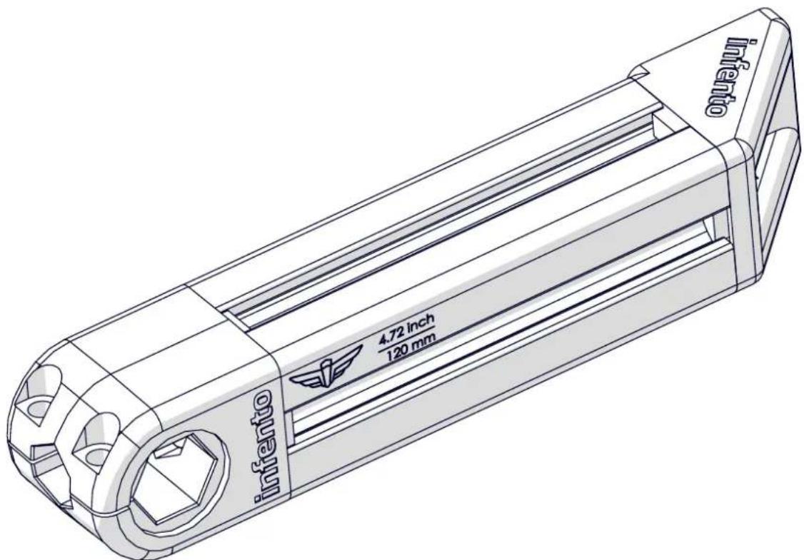
text_image
infento 4.72 inch 120 mm infento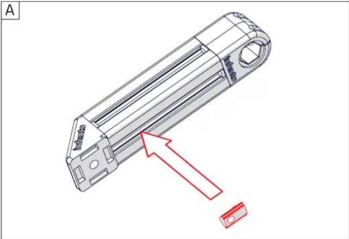
text_image
A Infra Infra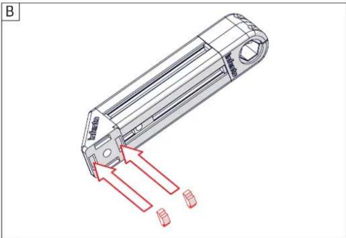
natural_image
Technical line drawing of a mechanical component with red arrows indicating flow or movement (no text or symbols)
natural_image
Technical line drawing of a mechanical component with labeled 'infanto' and 'INFANTO' features (no additional text or symbols)
+

+

2x
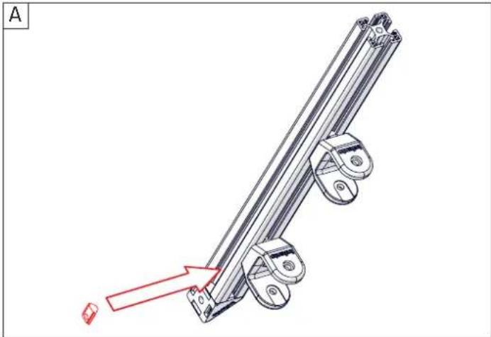
1x Profi le nut short
Bolt M8x20 2x (low head)
T-Positioning block
natural_image
Mechanical assembly diagram showing a lever mechanism with a red arrow indicating motion direction (no text or symbols present)
natural_image
Technical illustration of a mechanical bracket assembly with red arrows indicating motion or force direction (no text or symbols)
natural_image
Technical line drawing of two mechanical components, one cylindrical and one elongated, with no visible text or symbols.
natural_image
Technical line drawing of a mechanical component with red annotations indicating features (no readable text or symbols)
natural_image
Technical line drawing of a mechanical linkage component (no text or symbols)
+

+

2x
Profi le nut short
Bolt M8x20 2x (low head)
L-joint
4 T-Positioning block
natural_image
Technical line drawing of a mechanical assembly with red directional arrows indicating motion or force (no text or symbols)
natural_image
Technical line drawing of a mechanical conveyor system with red warning signs and blocks (no text or symbols)
natural_image
Technical line drawing of a mechanical bracket assembly (no text or symbols)

+
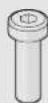
Bolt M8x25 2x (low head)

m = 311
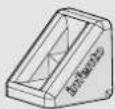
Protect cap
2x
natural_image
Technical line drawing of a mechanical assembly with no visible text or symbols
natural_image
Technical line drawing of a conveyor belt system with red components and motion indicators (no text or symbols)
natural_image
Technical line drawing of a mechanical linkage component (no text or symbols)
Positioning block
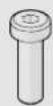
Bolt M8x25 2x (low head)

Bolt M5x6
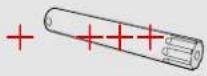
Handlebar short
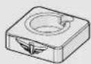
Axle plate
text_image
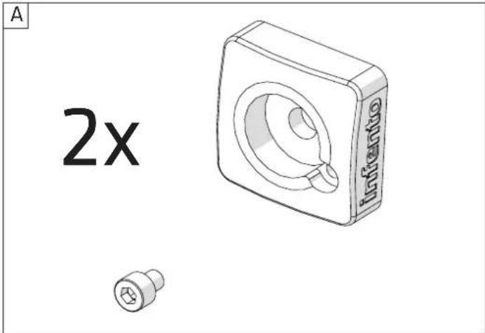
A 2x Infrante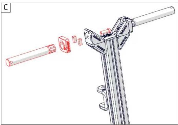
natural_image
Technical illustration of a mechanical assembly with red components and a cylindrical shaft (no text or symbols)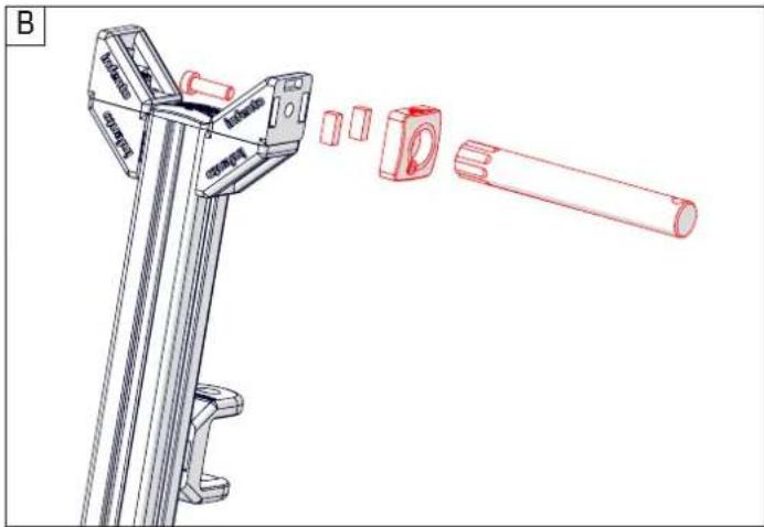
text_image
B M10000 M10000 M10000 M10000 M10000 M10000 M10000 M10000 M10000 M10000 M10000 M10000 M10000 M10000 M10000 N12545 N12545 N12545 N12545 N12545 N12545 N12545 N12545 N12545 N12545 N12545 N12545 N12545 N12545 N12545 M12545 M12545 M12545 M12545 M12545 M12545 M12545 M12545 M12545 M12545 M12545 M12545 M12545 M12545 M13678 M13678 M13678 M13678 M13678 M13678 M13678 M13678 M13678 M13678 M13678 M13678 M13678 M13678 M13678 N13678 N13678 N13678 N13678 N13678 N13678 N13678 N13678 N13678 N13678 N13678 N13678 N13678 N13678 N12999 N12999 N12999 N12999 N12999 N12999 N12999 N12999 N12999 N12999 N12999 N12999 N12999 N12999 N12999 M12999 M12999 M12999 M12999 M12999 M12999 M12999 M12999 M12999 M12999 M12999 M12999 M12999 M12999 M13678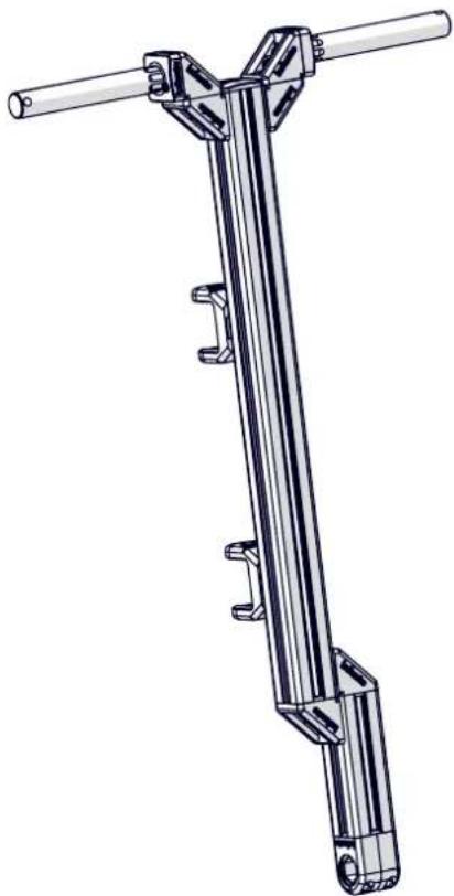
natural_image
Technical line drawing of a mechanical lever assembly (no text or symbols)
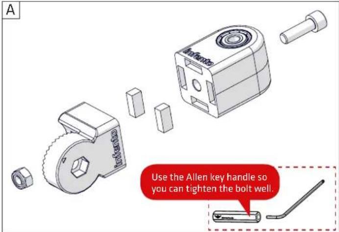
Angle limiter
40°

Locknut M8

Positioning block
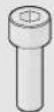
Bolt M8x25
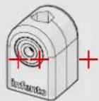
Bearing block
40x40_8
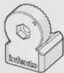
Multi angle joint
text_image
A Use the Allen key handle so you can tighten the bolt well.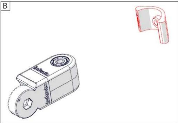
natural_image
Technical drawings of a mechanical clamp device and a U-shaped bracket component (no text or symbols)
text_image
infanto infanto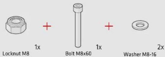
text_image
Locknut M8 1x Bolt M8x60 1x Washer M8-16 2x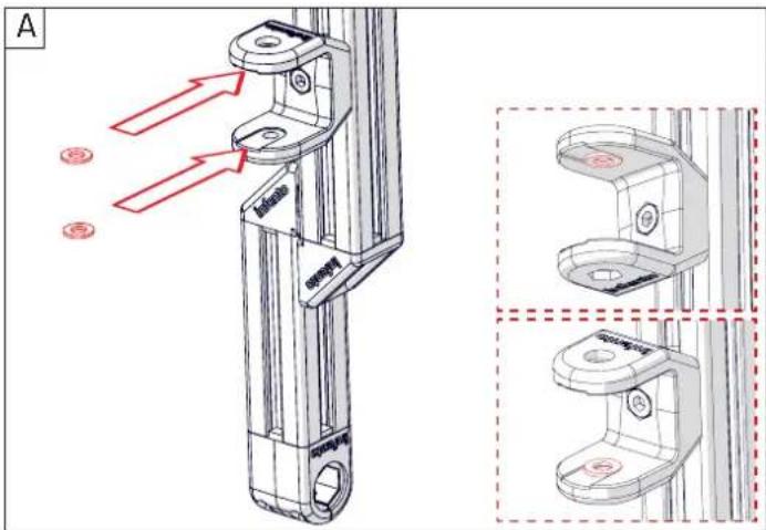
text_image
A B C D E F G H I J K L M N O P Q R S T U V W X Y Z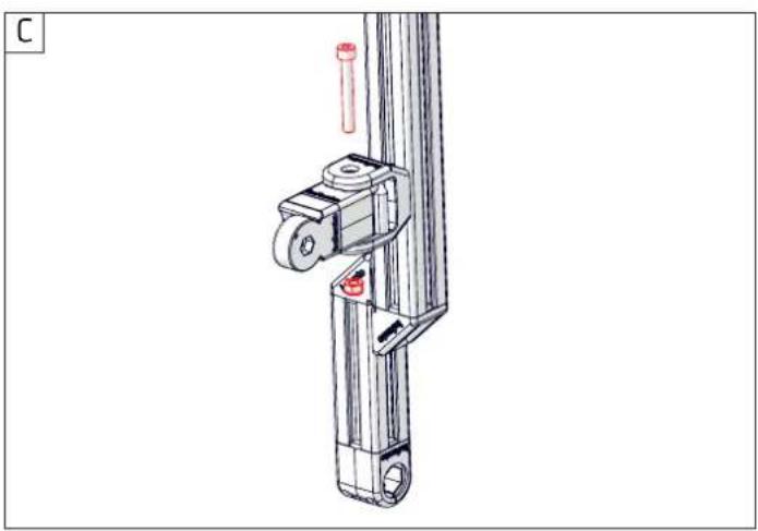
natural_image
Technical line drawing of a mechanical device with a cylindrical component and a red pin (no text or symbols)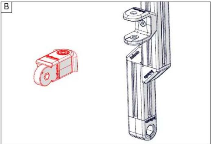
natural_image
Technical line drawing of a mechanical component with a red housing and a vertical bracket (no text or symbols)
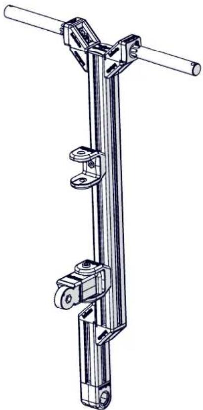
Between the U-block and the block bearing there have to be two washers. They ensure that there is space between the two blocks. Without it, the blocks would rub against each other, damage and twist heavily. With washers the gap is filled perfectly and you can tighten them securely.
natural_image
Technical line drawing of a mechanical lifting device with a shaft and mounting bracket (no text or symbols)
Angle limiter 40°

Locknut M8

Positioning block
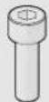
Bolt M8x25
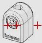
Bearing block 40x40_8
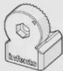
Multi angle joint
text_image
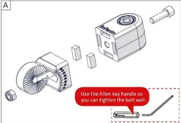
A Use the Allen key handle so you can tighten the bolt well.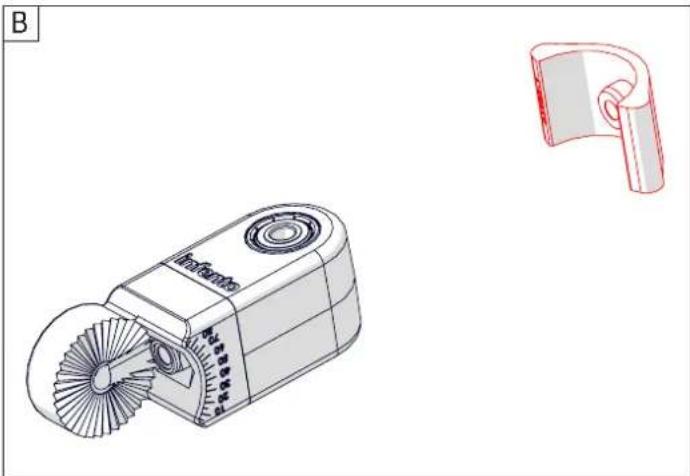
natural_image
Technical line drawing of a portable air purifier with fan blades and a separate 3D model (no text or symbols)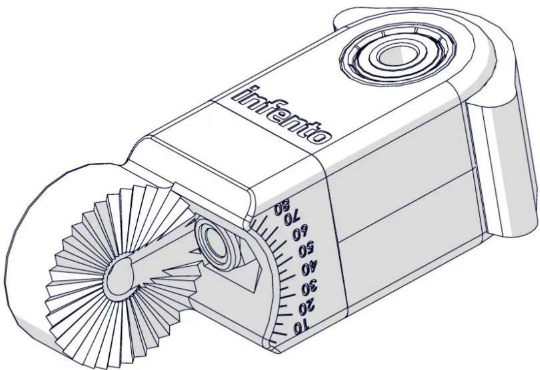
text_image
infemto 70 60 50 40 30 20 10
text_image
Locknut M8 1x Bolt M8x60 1x Washer M8-16 2x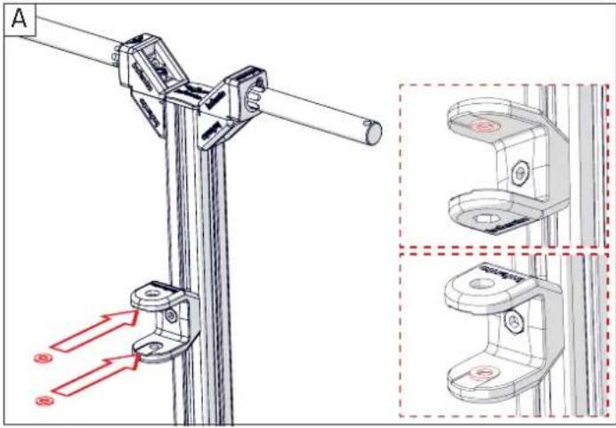
text_image
A ① ② ③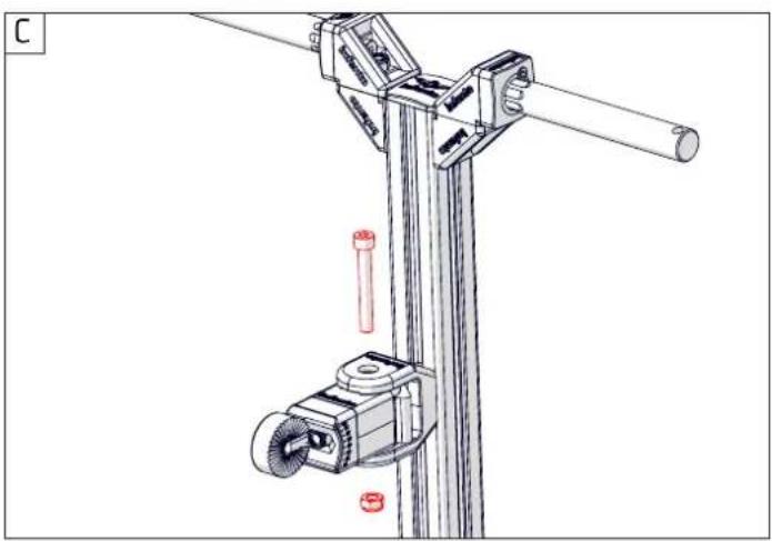
natural_image
Technical line drawing of a mechanical lifting device with a screw and shaft (no text or symbols)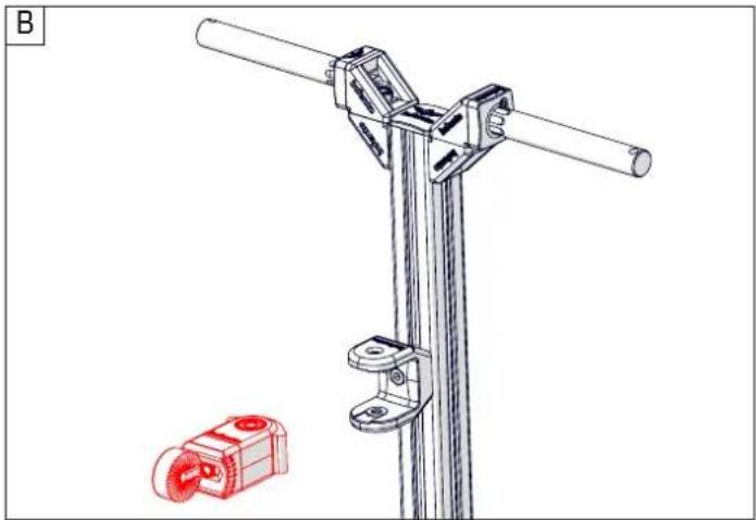
natural_image
Technical line drawing of a mechanical clamp or bracket assembly with a red component inset (no text or symbols)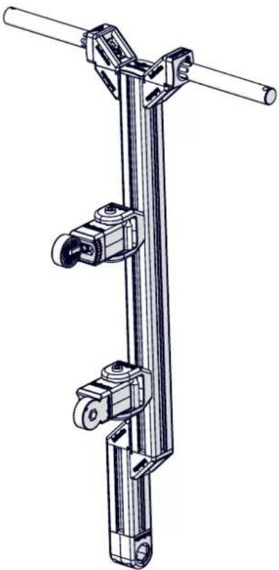
natural_image
Technical line drawing of a mechanical lifting device with two vertical supports and a central shaft (no text or symbols)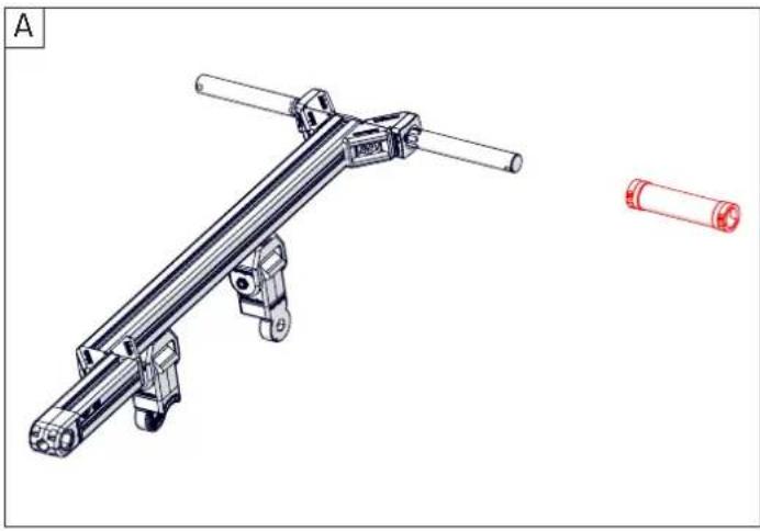
natural_image
Technical line drawing of a mechanical lever assembly with a separate red cylindrical component (no text or symbols)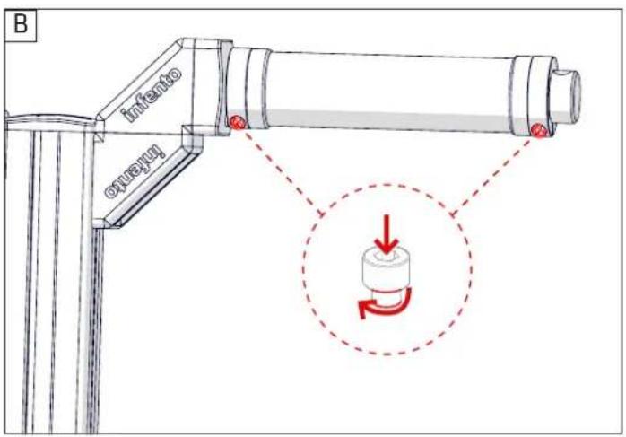
text_image
B Intento Oxyryl Dashed Circle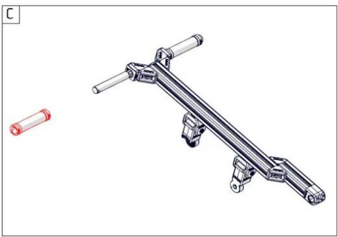
natural_image
Technical illustration of a mechanical lever assembly with two cylindrical components (no text or symbols)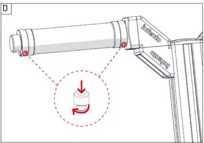
text_image
D infento oxuay D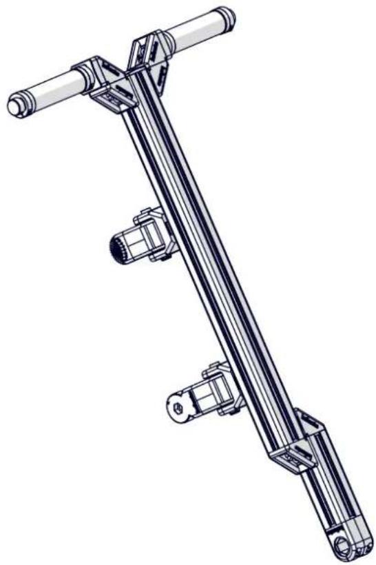
natural_image
Technical line drawing of a mechanical linkage assembly (no text or symbols)
Locknut M6

Bolt M6x25

2x
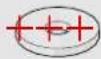
Washer M8-24

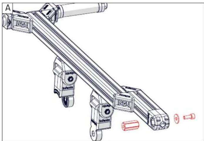
Bolt M8x20
1x
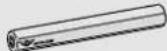
Axle 1x
1.57inch | 40mm
natural_image
Technical line drawing of a mechanical assembly with rollers and shafts (no text or symbols)C
natural_image
Technical illustration of a bicycle wheel assembly with mounting bracket and tire components (no text or symbols)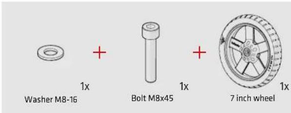
text_image
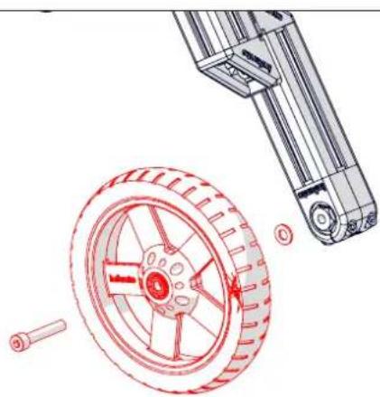
Washer M8-16 + 1x Bolt M8x45 + 1x 7 inch wheel 1xB

text_image
Tighten this bolt well, but not with full force because then you may damage the part.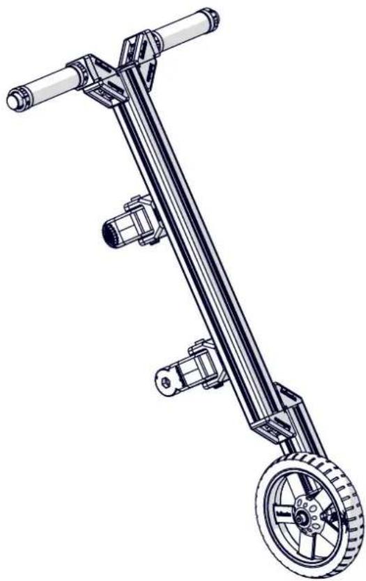
natural_image
Technical line drawing of a mechanical lever system with pulleys and wheels (no text or symbols)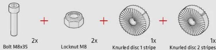
text_image
Bolt M8x35 + Locknut M8 + Knurled disc 1 stripe + Knurled disc 2 stripes 2x 2x 1x 1x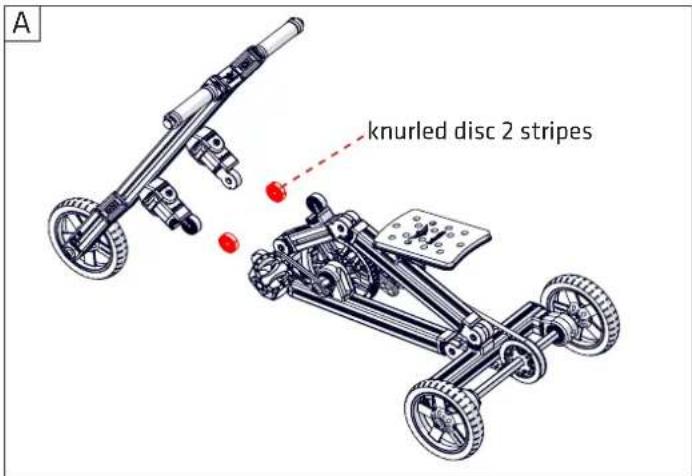
text_image
knurled disc 2 stripes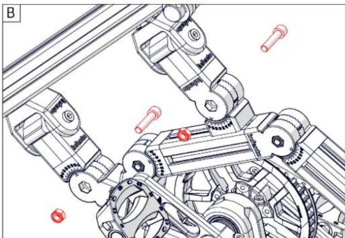
natural_image
Technical line drawing of a mechanical assembly with gears and linkages (no text or symbols)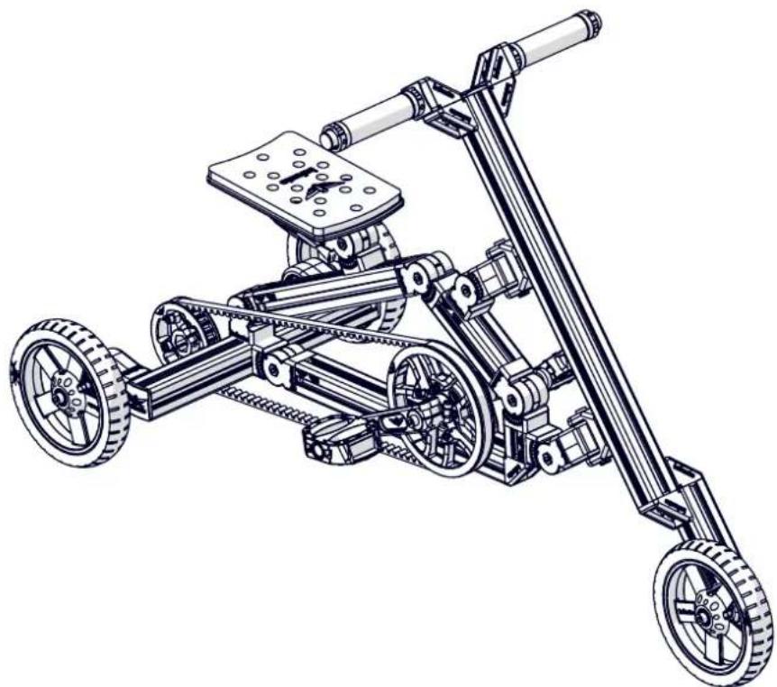
natural_image
Technical line drawing of a multi-wheeled robotic vehicle with wheels and a mounted platform (no text or symbols)BOOSTER ^G1
natural_image
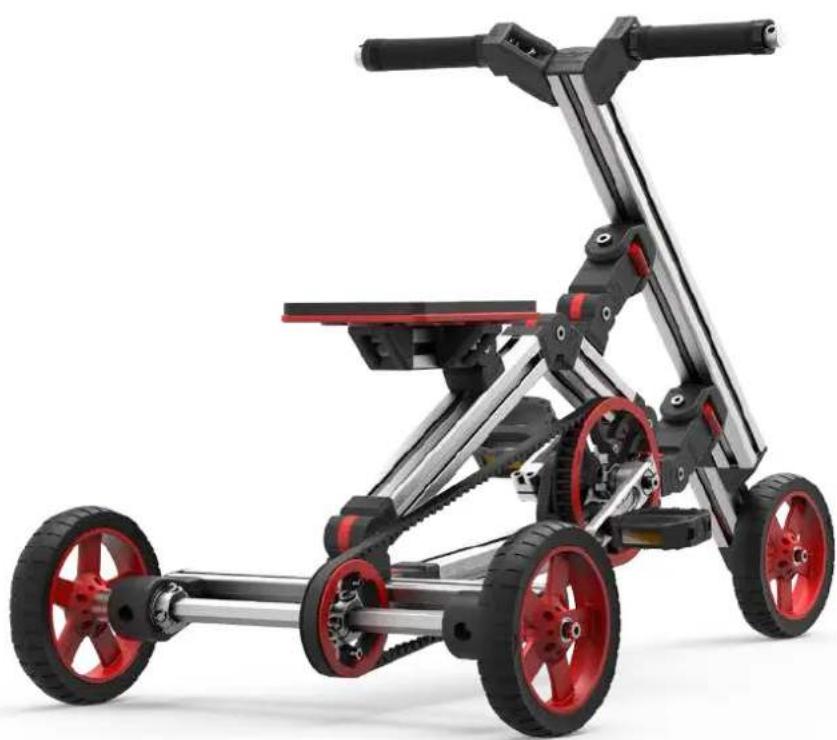
Modern multi-wheeled bicycle with black and red wheels, no visible text or symbolsTHANK YOU FOR READING ME!