
VSC 700D - Uncategorized Extron - Free user manual and instructions
Find the device manual for free VSC 700D Extron in PDF.


User questions about VSC 700D Extron
0 question about this device. Answer the ones you know or ask your own.
Ask a new question about this device
Download the instructions for your Uncategorized in PDF format for free! Find your manual VSC 700D - Extron and take your electronic device back in hand. On this page are published all the documents necessary for the use of your device. VSC 700D by Extron.
USER MANUAL VSC 700D Extron
Safety Instructions • English

This symbol is intended to alert the user of important operating and maintenance (servicing) instructions in the literature provided with the equipment.

This symbol is intended to alert the user of the presence of uninsulated dangerous voltage within the product's enclosure that may present a risk of electric shock.
Caution
Read Instructions • Read and understand all safety and operating instructions before using the equipment. Retain Instructions • The safety instructions should be kept for future reference.
Follow Warnings • Follow all warnings and instructions marked on the equipment or in the user information. Avoid Attachments • Do not use tools or attachments that are not recommended by the equipment manufacturer because they may be hazardous.
Power sources • This equipment should be operated only from the power source indicated on the product. This equipment is intended to be used with a main power system with a grounded (neutral) conductor. The third (grounding) pin is a safety feature, do not attempt to bypass or disable it.
Power disconnection • To remove power from the equipment safely, remove all power cords from the rear of the equipment, or the desktop power module (if detachable), or from the power source receptacle (wall plug).
Power cord protection • Power cords should be routed so that they are not likely to be stepped on or pinched by items placed upon or against them.
Servicing • Refer all servicing to qualified service personnel. There are no user-serviceable parts inside. To prevent the risk of shock, do not attempt to service this equipment yourself because opening or removing covers may expose you to dangerous voltage or other hazards.
Slots and openings • If the equipment has slots or holes in the enclosure, these are provided to prevent overheating of sensitive components inside. These openings must never be blocked by other objects.
Lithium battery • There is a danger of explosion if battery is incorrectly replaced. Replace it only with the same or equivalent type recommended by the manufacturer. Dispose of used batteries according to the manufacturer's instructions.
Avertissement
This equipment has been tested and found to comply with the limits for a Class A digital device, pursuant to part 15 of the FCC Rules. Operation is subject to the following two conditions:
- This device may not cause harmful interference.
- This device must accept any interference received, including interference that may cause undesired operation.
The Class A limits are designed to provide reasonable protection against harmful interference when the equipment is operated in a commercial environment. This equipment generates, uses, and can radiate radio frequency energy and, if not installed and used in accordance with the instruction manual, may cause harmful interference to radio communications. Operation of this equipment in a residential area is likely to cause harmful interference, in which case the user will be required to correct the interference at his own expense.
NOTE: This unit was tested with shielded cables on the peripheral devices. Shielded cables must be used with the unit to ensure compliance with FCC emissions limits. For more information on safety guidelines, regulatory compliances, EMI/EMF compliance, accessibility, and related topics, click here.
Conventions Used in this Guide
In this user guide, the following are used:
NOTE: A note draws attention to important information.
TIP: A tip provides a suggestion to make working with the application easier.
CAUTION: A caution indicates a potential hazard to equipment or data.
WARNING: A warning warns of things or actions that might cause injury, death, or other severe consequences.
Commands are written in the fonts shown here:
^AR Merge Scene,,Op1 scene 1,1 ^B51 ^W^C
[01] R000400300004000080000600 [02] 35 [17] [03]
Esc X1 *X17 * X20 * X23 * X21 CE
NOTE: For commands and examples of computer or device responses mentioned in this guide, the character "∅" is used for the number zero and "0" represents the capital letter "o."
Computer responses and directory paths that do not have variables are written in the font shown here:
Reply from 208.132.180.48: bytes=32 times=2ms TTL=32
C:\Program Files\Extron
Variables are written in slanted form as shown here:
ping xxx.xxx.xxx.xxx -t
SOH R Data STX Command ETB ETX
Selectable items, such as menu names, menu options, buttons, tabs, and field names are written in the font shown here:
From the File menu, select New.
Click the OK button.
Copyright
© 2011 Extron Electronics. All rights reserved.
Trademarks
All trademarks mentioned in this guide are the properties of their respective owners.
Contents
Introduction.... 1
About the VSC 500/700/700D .... 1
Features....1
Application Example 2
Rear Panel Connectors and Cabling 3
Genlock and Vertical Interval Switching (VSC 700 and 700D only) 5
Genlock Setup 5
Oscilloscope Displays....7
Optimizing the System....8
Front Panel Features 9
Menus, Configuration, and Adjustments......10
Moving Through Menus by Using Front Panel Controls 10
Menu Overview 11
Auto-Imaging Menu (Auto Set)....12
Output Configuration Menu (Output Config) 13
Filters Menu (Filters) 14
Zoom Menu (Zoom) 15
Genlock Menu (Genlock) 15
Exit Menu (Exit Menu)....16
Additional Functions.... 16
Size Function 16
Shift Function 17
Freeze Mode....17
Unit Reset Function....18
Front Panel Security Lockout (Executive Mode) 18
Troubleshooting....18
VSC Infrared Remote Control....20
Serial Communication....21
RS-232 Programming Guide....22
Host-to-VSC Communications....22
Video Scan Converter-initiated Messages ..... 22
Error Responses.... 23
Using the Command and Response Tables .... 23
Command and Response Table for SIS Commands: VSC 500/700/700D ....24
Command and Response Table for SIS Commands: VSC 700/700D Only....25
Command and Response Table for Special
Function SIS Commands: VSC 700/700D Only.. 25
Command and Response Table for Special Function SIS commands: VSC 500/700/700D ... 26
Control Software for Windows 26
Installing the Program....26 Using the Control Program....27
Firmware Upgrade from the Extron Website.....28
Downloading the Latest Firmware to the PC.. 28
Uploading the firmware from the PC to the VSC 29
Reference Information 30
Specifications: VSC 500 30
Specifications: VSC 700 and 700D ...... 31
Included Parts 34
Accessories 34
Firmware Upgrade Chip Installation 35
Mounting the VSC 36
Tabletop or Desktop Placement 37
Rack Mounting 37
Introduction
About the VSC 500/700/700D
The Extron VSC 500, 700, and 700D are computer-to-video scan converters that can convert computer images up to 1920 x 1200 for output as composite video, S-video, component video, SDI (VSC 700D), and/or RGB video. Applications include videoconferencing, video recording, and viewing of images on an NTSC or PAL monitor or other display device.
Key features include automatic setup of centering and sizing controls, horizontal filtering, an LCD window for user-friendly menu selections, memory presets (IR remote control feature), and a buffered loop-through for local monitor output. The VSCs can be controlled via the front panel, the optional IR remote control, or RS-232 commands.
Features
- Autoscanning — Automatically recognizes and down converts the incoming computer image, up to 1920 x 1200 resolution and 100 kHz horizontal and 120 Hz vertical scan rates.
- Input — Via a 15-pin HD female VGA connector (VSC 500) or BNC connectors (VSC 700/700D).
- Outputs — Simultaneously outputs RGB or component video, composite video, S-video, and SDI (VSC 700D).
• Memory presets — Recall up to eight user presets that can be stored and accessed via the optional IR remote. - Auto-Image™ setup — Automatic sizing and centering function to fill the output display screen.
- Centering and sizing and controls — Allow for user-friendly positioning and sizing of the image on-screen.
- Freeze/Reset button — The freeze function locks the output display to the current image.
- Front panel security lockout — Locks out all front panel functions except centering (shifting) to prevent accidental changes to adjustments.
- RS-232 remote control — An RS-232/RS-422 control port utilizes the Extron Simple Instruction Set (SISTM) of basic ASCII commands.
- Genlocking (VSC 700 and VSC 700D only) — Allows for the synchronizing of multiple input devices to a common external timing signal so that the switch between input devices will be clean.
- Horizontal filtering — Four selectable horizontal filters prevent aliasing or pixel elimination so that less detail is dropped when the image is scanned from left to right.
- Buffered loop-through — Provides a local monitor output, enabling the computer input signal to be monitored without the need for a separate distribution amplifier.
Installation and Operation
Application Example
The illustration below is one example of using the VSC 500.
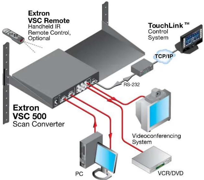
flowchart
graph TD
    A["Extron VSC Remote\nHandheld IR\nRemote Control, Optional"] --> B["Extron VSC 500\nScan Converter"]
    B --> C["PC"]
    B --> D["Videoconferencing System"]
    D --> E["VCR/DVD"]
    F["TouchLink™ Control System"] --> G["TCP/IP"]
    G --> B
    B --> H["RS-232"]
    H --> B
Figure 1. VSC 500 Application Example
Rear Panel Connectors and Cabling

text_image
1 2a 3a RGB INPUT BUFFERED LOOP-THROUGH B/B-YR/YR/R-Y WBS/8W/DEO GND STS/INPUTS RS-232 J422Figure 2. VSC 500 Rear Panel Connectors
text_image
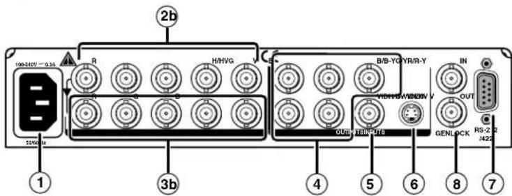
100-245V ~ 0.36 2b H/H/VG B/B-YG/YR/R-Y IN OUT GENLOCK RS-2/2 /422 DUN/YB/INTS 1 3b 4 5 6 8 7Figure 3. VSC 700 Rear Panel Connectors
text_image
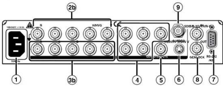
100-542V ~ 0.16 326 Hz 2b H/HVG 1 3b 1 DDI DH/PGTS 9 SDIB/B-XG VICH/R-VCH/V OUT GENLOCK RS-2/2 /42 4 5 6 8 7Figure 4. VSC 700D Rear Panel Connectors
NOTE: RGB, component video, composite video, S-video, and SDI video (VSC 700D only) are output simultaneously.
① AC power connector — Plug a standard IEC power cord into this connector to connect the scan converter to a 100 to 240 VAC, 50 Hz or 60 Hz power source.
②
a. RGB (computer) input VGA connector — Connect a computer video source (RGBHV, RGBS, RGsB) via this female VGA 15-pin connector.
TIP: D connector. Pins 4, 10, and 11 are internally grounded for ID bit termination.
b. RGB (computer) input BNC connectors — Connect a computer video source (RGBHV, RGBS, RGsB) via these five female BNC connectors. Connect cables for the appropriate signal type, as shown here.
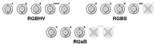
text_image
RGBHV RGBS RGsB③
a. Buffered loop-through VGA connector — For local monitor output of the input, connect a monitor to this female VGA 15-pin HD connector.
b. Buffered loop-through BNC connectors — For local monitor output of the input, connect a monitor to these five female BNC connectors. Connect cables for the appropriate signal type as shown in 28 above.
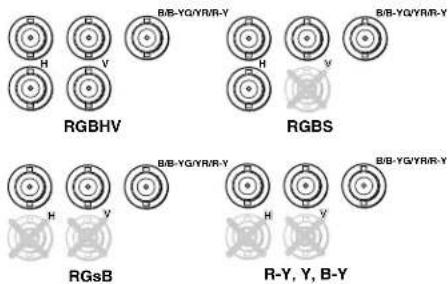
④ Output BNC connectors — Connect coaxial cables from a display device to these five female BNC connectors for RGBHV, RGBS, RGsB, or component video output, as follows:
text_image
RGBHV B/B-YQ/YR/R-Y RGBS B/B-YQ/YR/R-Y RGsB B/B-YQ/YR/R-Y B/B-YQ/YR/R-Y R-Y, Y, B-Y⑤ Composite video output connector — Using a coaxial cable, connect a composite video display device to this female BNC connector.
⑥ S-video output connector — Connect an S-video output device to this female 4-pin mini DIN connector.
⑦ RS-232/RS-422 port — This connector provides for two-way RS-232/RS-422 communication. See "Serial Communication", for information on how to install and use the control software and SIS commands.
The default protocol is 9600 baud, 1 stop bit, no parity, and no flow control.
The rear panel RS-232/RS-422, 9-pin connector has the following pin assignments:
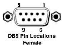
| Pin | RS-232 function Description |
| 1 No | connection |
| 2 Tx | Transmit data |
| 3 Rx | Receive data |
| 4 Tx | 2 Transmit data |
| 5 Gnd | Signal ground |
| 6 No | connection |
| 7 No | connection |
| 8 Rx | 2 Receive data |
| 9 No | connection |
| Pin | RS-422 function Description |
| 1 No | connection |
| 2 Tx+ | Transmit ground |
| 3 Rx- | Receive ground |
| 4 No | connection |
| 5 Gnd | Signal ground |
| 6 No | connection |
| 7 Rx+ | Receive data |
| 8 Tx | + Transmit data |
| 9 No | connection |
⑧ Genlock input and output connectors — Connect an external blackburst signal to the input (In) female BNC connector for genlocking the video signal in broadcast or other sync-critical applications.
Connect any downstream equipment, which requires genlocking, to the output (Out) female BNC connector to route the blackburst signal throughout the system in broadcast or other sync-critical applications. See Genlock and Vertical Interval Switching.
⑨ SDI (serial digital interface) connector — Connect an SDI signal to this female BNC connector.
Genlock and Vertical Interval Switching (VSC 700 and 700D only)
For vertical interval switching (to allow clean switching between signals from several devices during the vertical blanking period of each signal), a composite sync signal can be applied at the Genlock In connector, and it can also be passed to another device via the Genlock Out connector.
If the genlock connectors are used only for vertical interval switching, no horizontal or subcarrier phase adjustments are required.
Genlock Setup
Genlock differs from simple vertical interval switching in that an external device (a black burst generator) generates a reference sync signal for the system, and every device that uses that signal has its output horizontal signal and subcarrier phases adjusted to exactly match that of the generator to allow precise timing and full synchronization. Genlocked systems produce cleaner switches between inputs than do those without this type of synchronization.
An oscilloscope is required for genlock setup, and a vectorscope is recommended.
Waveform monitors of types other than a vectorscope may give the appearance that timing is adjusted correctly when it is 180 degrees out of phase, which results in incorrect colors or picture artifacts.
To synchronize the video output of the VSC with a genlock signal, follow these steps:
NOTE: All equipment in the system must be powered up and turned on for at least 15 to 20 minutes before genlock setup adjustments can be made and before the equipment is used in a genlocked application.
- Power up and turn on all the devices that will use the genlock signal. The devices must be on for at least 15 to 20 minutes before proceeding with any adjustments.
-
Connect the active timing source signal to the Genlock In connector on the rear panel.
-
Connect the video input signals to the VSC, as described previously in this section.
- Connect the oscilloscope ("scope") probe A to the Genlock Out connector. This will provide the reference signal of the scope. In order to avoid altering the genlock signal, use the cabling configuration that will be used in the installation. Either connect the genlock signal cable from the scope to the next device in the system to be timed, or provide 75 ohm termination at the genlock output of the VSC.

text_image
Timing Source 75 ohm Terminator To Scope Probe B 75 ohm Terminator To Scope Probe A- Connect scope probe B to the composite video output connector (VID) of the VSC. Either connect the genlock signal cable from the scope to the next device in the system to be timed, or provide 75 ohm termination at the composite output of the VSC as shown in the previous diagram.
- Using the instructions for the scope you are using, set the scope to view the horizontal phases of the signal. Adjust the horizontal phase by rotating the Adjust horizontal (◀) knob (see the "Genlock Menu" section in this chapter). Adjust the horizontal phase until there is no (0°) difference between the composite video output's horizontal sync phase and the genlock signal's horizontal phase. See the "Oscilloscope Displays" section.
- Set the scope to view the subcarrier signals. Adjust the sub phase by rotating the Adjust vertical ( ) knob until there is a zero phase difference between the genlock signal and the NTSC/PAL output (see the "Genlock Menu" section).
- View the horizontal phases again. If the phase difference is not zero, repeat steps 6 and 7 until the settings do not change.
- Once the settings are stable, disconnect the oscilloscope, and reconnect the genlock cables.
- Check the displays for proper colors and for undesirable artifacts in the images. Make adjustments as necessary.
- If other VSCs are part of this genlock daisy chain, connect the oscilloscope to each device, and repeat this procedure.
Oscilloscope Displays
What you see on the oscilloscope while adjusting the VSC to match the genlock signal depends on the type of signal used, the type of oscilloscope, and the procedure the scope requires. This section shows some examples of oscilloscope displays.
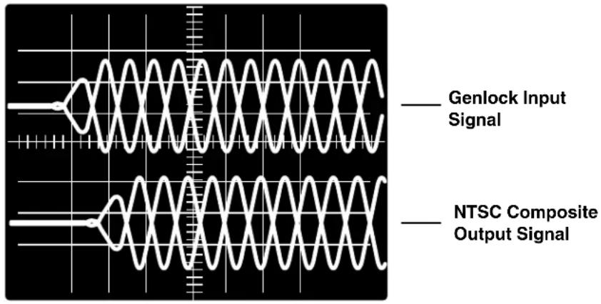
The following diagram shows the genlock input signal (top) and an out-of-alignment NTSC composite sync output signal (bottom) displayed on a waveform monitor to check for alignment. When the phases are aligned, the wave peaks on the bottom waveform should line up with those in the reference signal above it.
text_image
Genlock Input Signal NTSC Composite Output SignalFigure 5. Superimposed Waveforms
With this method there is no way to know if the signals are 180^ out of phase. A delayed sweep on a time-based scope would allow a more accurate display of the input and output signal phase relationships.
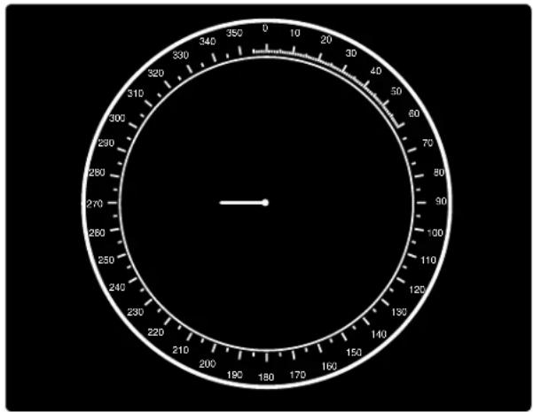
A vectorscope is more accurate than a waveform monitor. The following diagram shows an example of a vectorscope display when the horizontal phase is adjusted to align it with the burst (genlock) vector. Adjust the horizontal phase by rotating the Adjust horizontal (◀▶) knob until the difference between the two vectors is 0^ . This example shows black burst only (with no color). The burst vector is pointing to the left from the center.
natural_image
Circular analog clock face with hour and minute hands (no text or numbers visible)Figure 6. Vectorscope Screen During Horizontal Phase Adjustment
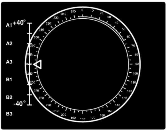
The following diagram shows an example of a view of a vectorscope during adjustment of the color subcarrier phase (SC/H). The subcarrier phase should be aligned to 0^ (indicated in the figure by the triangle.
text_image
A1+40° A2 A3 B1 B2 -40° B3Figure 7. Vectorscope Screen During Color Subcarrier Phase Adjustment
Optimizing the System
For optimal performance, follow the steps in this section in order when setting up the VSC and its input and output devices.
Select the output standard
From the Video standard submenu, select the output standard (see the Video standard submenu section).
- NTSC (default)
PAL
Size the image to fill the screen
- Size and center the displayed image to fill the output screen (see the Auto-Imaging Menu section).
- Press the Size button on the front panel (see the Front Panel Features section).
- Rotate the horizontal and vertical adjustment knobs to resize the displayed image. Observe the picture on screen as you adjust the controls. The Min/Max LED will light red whenever the minimum or maximum limit of an adjustment knob is reached.
- Press the Size button again to turn the size feature off.
- Center the picture by rotating the horizontal and vertical adjustment knobs. Observe the picture on screen as you adjust the controls. The Min/Max LED will light red whenever the minimum or maximum limit of an adjustment knob is reached.
- Repeat steps 1 through 5 as needed.
Select the filtering levels
- From the Filters menu, select the Flicker filter adjustment submenu (see the Filters menu section). Rotating the horizontal or vertical adjustment knob and observing the image, select the filtering level that produces the least amount of flickering.
- From the Horizontal filter adjustment submenu, rotate the horizontal or vertical adjustment knob to reduce loss of detail in the scan converted image.
- From the Encoder adjustment submenu, rotate the horizontal or vertical adjustment knob to select from among encoding levels to maintain image sharpness.
NOTE: If the filters are set before the image size is adjusted, you must set the filters again after adjusting the image size..
Front Panel Features
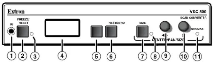
text_image
Extron VSC 500 IR FREEZE/ RESET NEXTMENU SIZE CENTER/PAN/SIZE SCAN CONVERTER MIN/MAX 1 2 3 4 5 6 7 8 9 10 11Figure 8. VSC Front Panel Features
① Infrared remote sensor — This sensor is used to receive infrared (IR) signals from the IR remote control. The IR remote control must be pointed directly at this sensor for best results. See the VSC Infrared Remote Control section.
② Freeze and Reset button — Press this button to “freeze” or lock the output display of the scan-converted image to the current image. While in this mode, all front panel controls will be disabled and the Freeze and Reset LED (see ③) will light green. Pressing this button again will reset (disable) the freeze function and enable the front panel controls.
Pressing this button while in the sizing, centering (shifting), or filtering menus will reset those menu settings to the factory default. See the Size function section, Shift function section, and Filters Menu section.
NOTE: The scan converter stores the current input image and will not drop the frozen output display when the input signal is lost. The image on the buffered loop-through display will not be frozen.
③ Freeze and Reset LED — When the Freeze and Reset button is pressed, this indicator lights green.
④ LCD — This two-row liquid crystal display provides a way to see the menus and options for setting up the scan converter.
⑤ Menu button — Press this button to enter the setup main menus and to move from menu to menu.
⑥ Next button — Press this button to enter a specific submenu of a selected main menu.
NOTES: • Press the Next and Size buttons simultaneously for two seconds to enable or disable the front panel security lockout feature. When this feature is enabled, adjustments and changes to the scan converter setup cannot be made from the front panel controls, but centering adjustments can still be made using the horizontal and vertical adjustment knobs. See the Front panel security lockout (executive mode) section in this chapter.
- Pressing the Menu and Next buttons simultaneously while applying power to the VSC will reset the VSC to factory default settings (see the Unit Reset Function section).
⑦ Size button — Press this button and rotate the horizontal and vertical adjustment knobs to resize the displayed image horizontally and vertically.
⑧ Size LED — When the Size button is pressed, this indicator lights green.
⑨ Horizontal adjustment knob (◀) — In the menu system, rotate this knob to scroll through menu options and make adjustments. Horizontal sizing and centering are also adjusted with this knob when the image size does not exceed screen size. When the image size exceeds screen size, horizontal panning can be adjusted from the Zoom menu (see Zoom Menu in this section).
NOTE: When not in a menu, rotating this knob will shift the image horizontally.
10 Vertical adjustment knob (▲) — In the menu system, rotate this knob to scroll through menu options and make adjustments. Vertical sizing and centering can be adjusted with this knob when the image size does not exceed screen size. When the image size exceeds screen size, vertical panning can be adjusted from the Zoom menu (see Zoom Menu in this section).
NOTE: When not in a menu, rotating this knob will shift the image vertically.
⑪ Min/Max LED — This indicator lights red whenever the minimum or maximum limit of an adjustment using the horizontal (◀) or vertical (◆) adjustment knob has been reached.
Menus, Configuration, and Adjustments
VSC configuration and adjustments can be performed by using the Windows®-based control program (see chapter three for details) or by using the front panel controls and the menus that are displayed on the VSC's LCD screen.
Moving Through Menus by Using Front Panel Controls
- Menu button — Press the Menu button to activate menus and to scroll to the main menus. After ten seconds of inactivity, the VSC will time out and return to the default menu cycle.
- Next button — Press the Next button to move between the submenus of a selected main menu.
- Adjust (◀▶, ◆) knobs — In configuration mode rotate the Adjust horizontal (◀▶) knob and Adjust vertical (◀) knob to scroll through submenu options and to make adjustment selections. Refer to the flowcharts in this chapter and to specific sections for explanations on knob adjustments.
Menu Overview
The default menus appear on the LCD when no adjustments are actively being made. They cycle between the screen showing the name of the VSC (VSC 500/700/700D) and the screen that shows the horizontal and vertical frequencies of the input signal, as shown below.

Figure 9. Default menu cycle with input signal

Figure 10. Default menu cycle without input signal
NOTES: From any menu or submenu, after ten seconds of inactivity the VSC will save all adjustment settings and time out to the default menus.
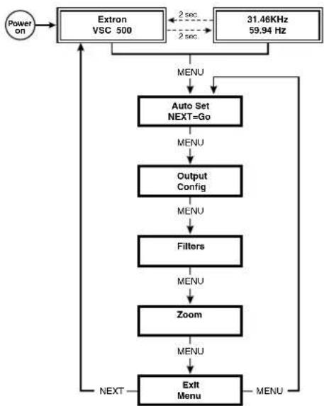
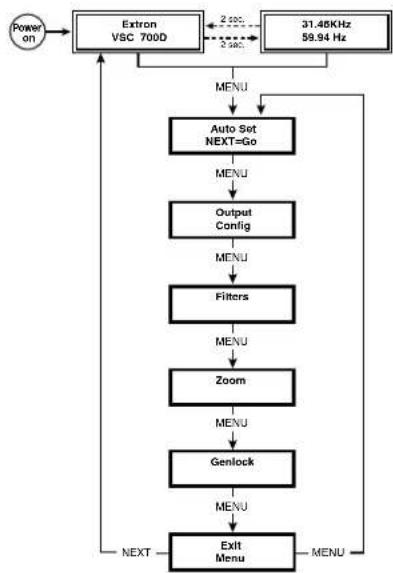
The main menus are as shown in the following flowcharts. The main menus for the VSC 500, 700, and 700D are identical except for the additional genlocking menu for the VSC 700 and 700D. Use the Menu button to scroll between main menus.
flowchart
graph TD
    A["Power on"] --> B["Extron VSC 500"]
    B --> C["31.46KHz 59.94 Hz"]
    C --> D["Auto Set NEXT=Go"]
    D --> E["Output Config"]
    E --> F["Filters"]
    F --> G["Zoom"]
    G --> H["Exit Menu"]
    H --> I["NEXT"]
    I --> J["MENU"]
    J --> B
    B -->|2 sec| K["2 sec"]
    K --> C
    C -->|2 sec| L["2 sec"]
    L --> B
Figure 11. Main Menus for the VSC 500
flowchart
graph TD
    A["Power on"] --> B["Extron VSC 700D"]
    B --> C["31.48KHz 59.94 Hz"]
    C --> D["Auto Set NEXT=Go"]
    D --> E["OUTPUT Config"]
    E --> F["Filters"]
    F --> G["Zoom"]
    G --> H["Genlock"]
    H --> I["EXIT Menu"]
    I --> J["NEXT"]
    J --> B
    B --> K["MENU"]
    K --> D
    D --> L["MENU"]
    L --> F
    F --> M["MENU"]
    M --> G
    G --> N["MENU"]
    N --> H
    H --> O["MENU"]
    O --> I
Figure 12. Main Menus for the VSC 700 and 700D
Auto-Imaging Menu (Auto Set)
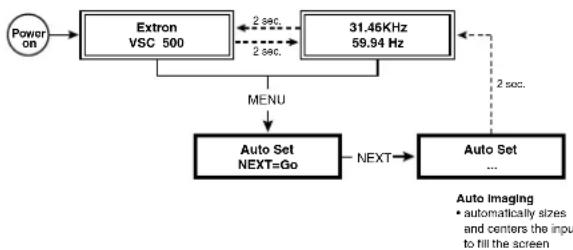
The following flowchart illustrates the Auto-Image™ feature. Pressing the Next button will display the submenu and automatically size and center the displayed image to fill the output screen.
flowchart
graph TD
    A["Power on"] --> B["Extron VSC 500"]
    B --> C["31.46KHz 59.94 Hz"]
    C --> D["Auto Set NEXT=Go"]
    D --> E["Auto Set ..."]
    F["MENU"] --> D
    G["2 sec."] --> B
    H["2 sec."] --> C
    I["2 sec."] --> D
    J["Auto Imaging"] --> K["• automatically sizes and centers the input to fill the screen"]
Figure 13. Auto Imaging Menu
NOTES: • If you press the Menu button while a submenu is active, the next main menu becomes active. For example, the menu changes from the Auto Set submenu to the Output Configuration main menu.
- To return to the default menu cycle, let the VSC time out for 10 seconds, or press the Menu button until the Exit Menu menu appears, then press the Next button.
Output Configuration Menu (Output Config)
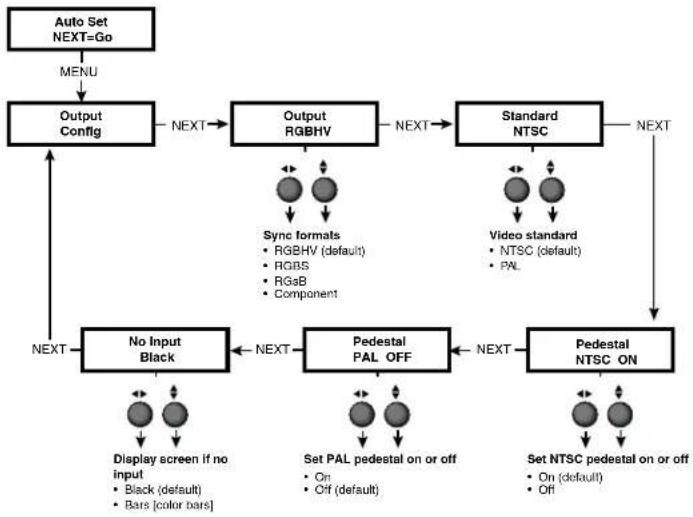
The following flowchart provides an overview of the Output Configuration menu.
flowchart
graph TD
    A["Auto Set NEXT=Go"] --> B["MENU"]
    B --> C["Output Config"]
    C --> D["Next"]
    D --> E["Output RGBHV"]
    E --> F["Next"]
    F --> G["Standard NTSC"]
    G --> H["Next"]
    H --> I["Pedestal NTSC ON"]
    I --> J["Next"]
    J --> K["No Input Black"]
    K --> L["Display screen if no input\n• Black (default)\n• Bars [color bars"]]
    K --> M["Next"]
    M --> N["Pedestal PAL OFF"]
    N --> O["Next"]
    O --> P["Set PAL pedestal on or off\n• On\n• Off (default)"]
    O --> Q["Next"]
    Q --> R["Video standard\n• NTSC (default)\n• PAL"]
    R --> S["Output RGBHV"]
    S --> T["Sync formats\n• RGBHV (default)\n• RGBS\n• RGsB\n• Component"]
    S --> U["Next"]
Figure 14. Output Configuration Menu
Output signal submenu (Output)
The VSC will simultaneously output RGB, Composite video, S-video, and SDI (VSC 700D only). The RGB type must be selected from this submenu.
The VSC Rotate the horizontal (◀▶) or vertical adjustment knob (◀) to select from the following sync formats:
- RGBHV (default)
- RGBS
RGsB - Component
Video standard submenu (Standard)
The VSC offers a choice of video standards. Rotate the horizontal (◀) or vertical adjustment knob (♦) to select from the following video standards:
- NTSC (default)
PAL
Set NTSC pedestal submenu (Pedestal NTSC)
The pedestal for NTSC video format may be turned on or off. Pedestal is an offset that separates the active video from the blanking level. When pedestal is set to Off, black and blanking level are the same because there is no longer an offset between blanking level and active video. Rotate the horizontal (◀) or vertical adjustment knob (◀) to turn the pedestal on or off.
Set PAL pedestal submenu (Pedestal PAL)
The pedestal for PAL video format may be turned on or off. Rotate the horizontal (◀) or vertical adjustment knob (◆) to turn the pedestal on or off.
No input signal display type submenu (No Input)
When no input is present, the VSC offers two types of outputs. Rotate the horizontal (◀) or vertical adjustment knob (◀) to select from among the following display types when no input signal is present:
- Black screen (default)
- Bars (color bars)
Filters Menu (Filters)
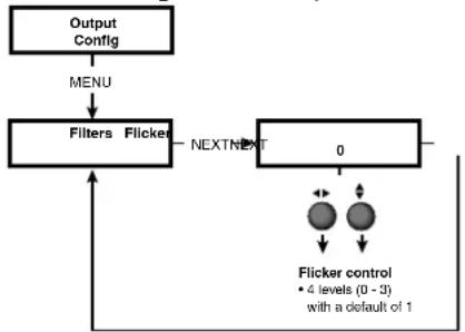
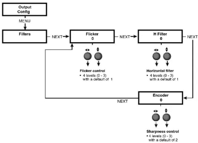
The following flowcharts provides an overview of the Filters menu.
flowchart
graph TD
    A["Output Config"] --> B["MENU"]
    B --> C["Filters Flicker"]
    C --> D["NEXTNEXT"]
    D --> E["0"]
    E --> F["Flicker control\n• 4 levels (0 - 3)\nwith a default of 1"]
    F --> G["↑"]
    G --> C
Figure 15. VSC 500 Filters Menu
flowchart
graph TD
    A["Output Config"] --> B["MENU"]
    B --> C["Filters"]
    C --> D["Flicker 0"]
    D --> E["H Filter 0"]
    E --> F["Encoder 0"]
    F --> G["Sharpness control\n4 levels (0 - 3) with a default of 2"]
    D --> H["Flicker control\n4 levels (0 - 3) with a default of 1"]
    E --> I["Horizontal filter\n4 levels (0 - 3) with a default of 1"]
    F --> J["NEXT"]
    J --> D
    J --> E
    J --> F
Figure 16. VSC 700 and 700D Filters Menu
Flicker filter adjustment submenu (Flicker)
Rotate the horizontal (◀▶) or vertical adjustment knob (▲) to select from four levels (0 to 3) of filtering to reduce display output flicker. The default is 1.
Horizontal filter adjustment submenu (H Filter)
Rotate the horizontal (◀) or vertical adjustment knob (♦) to select from four levels (0 to 3) of horizontal filtering to reduce loss of detail in the scan converted video image. The default is 1.
Encoder adjustment submenu (Encoder)
Rotate the horizontal (◀) or vertical adjustment knob (▲) to select from four levels (0 to 3) of encoding to maintain image sharpness. The default is 2.
Zoom Menu (Zoom)
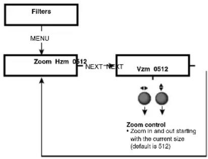
The following flowchart provides an overview of the Zoom menu.
flowchart
graph TD
    A["Filters"] --> B["MENU"]
    B --> C["Zoom Hzm 0512"]
    C --> D["NEXT"]
    D --> E["Vzm 0512"]
    E --> F["Zoom control\n• Zoom in and out starting with the current size (default is 512)"]
    F --> G["->"]
    G --> C
Figure 17. Zoom Menu
Zoom in/out adjustment submenu (Zoom)
Rotate the horizontal (◀) or vertical adjustment knob (◀) to adjust the zoom settings of a displayed image. The zoom adjustment increases or decreases the overall size of an image and is based on the current size setting. See Front Panel Features in this section for a description of the Size button.
NOTE: The default value for horizontal and vertical size is 0512. The default values for the horizontal and vertical shift are 2048 and 1024, respectively. The actual minimum and maximum values will vary and are based on the incoming scan rate.
Genlock Menu (Genlock)
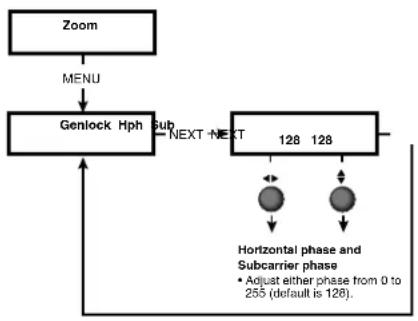
The following flowchart describes the Genlock menu. Genlocking is available on the VSC 700 and 700D only.
flowchart
graph TD
    A["Zoom"] --> B["MENU"]
    B --> C["Genlock Hph"]
    C --> D["SUB"]
    D --> E["NEXT"]
    E --> F["128"]
    F --> G["128"]
    G --> H["Horizontal phase and Subcarrier phase\n• Adjust either phase from 0 to 255 (default is 128)."]
    C --> I["↑"]
    I --> J["↓"]
Figure 18. VSC 700 and 700D Genlock Menu
Horizontal and Subcarrier Phase submenu (Hph Sub)
Rotate the horizontal (◀) and vertical adjustment knob (◀) to adjust the horizontal phase and color subcarrier phase, respectively (see Genlock and Vertical Interval Switching in this section). Adjust either phase from 0 to 255. The default is 128.
Exit Menu (Exit Menu)
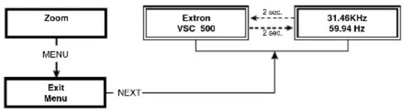
The following flowchart describes the Exit menu. Pressing the Next button from this menu will return you to the default menu cycle.
flowchart
graph TD
    A["Zoom"] --> B["MENU"]
    B --> C["Exit Menu"]
    C --> D["Next"]
    E["Extron VSC 500"] --> F["2 sec."]
    F --> G["31.46KHz 59.94 Hz"]
    G --> H["2 sec."]
    H --> I["Next"]
Figure 19. Exit Menu
Additional Functions
In addition to the main menu system, there are several other functions that are featured by the VSC 500, 700, or 700D. Image sizing, shifting, freezing, a unit reset function, and an executive mode to disable the front panel controls are also available.
Size Function
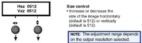
Press the Size button at any time to adjust the size of a displayed image.
text_image
Hsz 0512 Vsz 0512 Size control • Increase or decrease the size of the image horizontally (default is 512) or vertically (default is 512) NOTE: The adjustment range depends on the output resolution selected.Figure 20. Size Adjustment
Rotate the horizontal knob (◀) and vertical adjustment knob (◀) to adjust the horizontal and vertical dimensions, respectively, of the image. The adjustment setting, which is displayed in the menu display, varies according to the resolution of the display device. The defaults are 512 for both the horizontal and vertical size.
The Size LED will light green when the Size button is pressed, and the Min/Max LED will light red whenever the adjustment range has reached its limit. Pressing the Size button again returns you to the default menu cycle, and pressing the Next button advances you to the Shift menu, as described below (see Front Panel Features in this section).
Shift Function
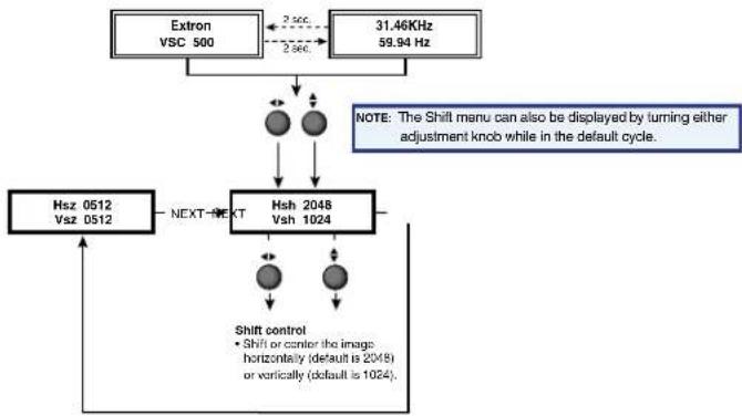
The following flowchart describes the shift feature. Shift an image to center it or move it horizontally and vertically. From the default cycle, rotating either adjustment knob will display the Shift menu. The Shift menu will also display when the Next button is pressed from the Size menu.
flowchart
graph TD
    A["Extron VSC 500"] --> B["3. sec."]
    C["31.46KHz 59.94 Hz"] --> D["2 sec."]
    B --> E["Hsh 2048 Vsh 1024"]
    D --> E
    E --> F["SHIFT control\n• Shift or control the image: horizontally (default is 2048) or vertically (default is 1024)."]
    F --> G["Hsz 0512 Vsz 0512"]
    G --> H["NEXT→NEXT"]
    H --> E
    style A fill:#f9f,stroke:#333
    style C fill:#f9f,stroke:#333
    style E fill:#ccf,stroke:#333
    style F fill:#cfc,stroke:#333
Figure 21. Shift Adjustment
Rotate the horizontal (◀) or vertical adjustment knob (◆) to shift the image horizontally or vertically, respectively.
The Min/Max LED will light red whenever the adjustment range has reached its limit. Pressing the Next button returns you to the Size menu.
NOTE: The default value for horizontal and vertical size is 0512. The default values for the horizontal and vertical shift are 2048 and 1024, respectively. The actual minimum and maximum values will vary and are based on the incoming scan rate.
Freeze Mode
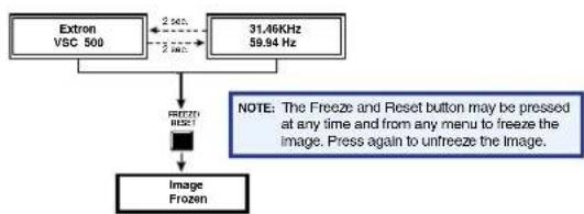
The displayed image may be prevented from being changed by pressing the Freeze and Reset button at any time to enable this function. The Freeze and Reset LED will light green when this button is pressed. Pressing the Freeze and Reset button again disables this function (see note below) (see Front Panel Features in this section).
NOTE: If freeze mode is enabled, pressing the Next button from the Auto Set main menu will disable freeze mode.
flowchart
graph TD
    A["Extron VSC 500"] --> B["2.6Hz"]
    A --> C["31,46KHz 59.94 Hz"]
    C --> D["RESET"]
    D --> E["Image Frozen"]
    note["NOTE: The Freeze and Reset button may be pressed at any time and from any menu to freeze the image. Press again to unfreeze the image."] --> D
Figure 22. Freeze Function
Unit Reset Function
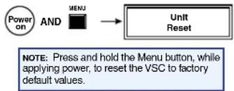
To reset the VSC to the factory default settings, apply power to the VSC while pressing the Menu button.
flowchart
graph LR
    A["Power on"] --> B["AND"]
    B --> C["MENU"]
    C --> D["Unit Reset"]
Figure 23. Unit reset function
Front Panel Security Lockout (Executive Mode)
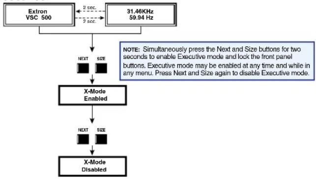
To prevent accidental changes to settings, simultaneously press the Next and Size buttons for two seconds to enable the front panel security lockout (Executive mode) of the VSC. Executive mode locks all front panel functions except centering (shifting). When executive mode is active, all functions and adjustments can still be made through RS-232 control. For details on RS-232 control, see the "Serial Communication" section.
To disable Executive mode, simultaneously press the Next and Size buttons again for two seconds.
flowchart
graph TD
    A["Extron VSC 500"] --> B["NEXT SIZE"]
    C["31.46KHz 59.94 Hz"] --> B
    B --> D["X-Mode Enabled"]
    D --> E["NEXT SIZE"]
    E --> F["X-Mode Disabled"]
    note["NOTE: Simultaneously press the Next and Size buttons for two seconds to enable Executive mode and lock the front panel buttons. Executive mode may be enabled at any time and while in any menu. Press Next and Size again to disable Executive mode."] --> D
Figure 24. Front Panel Security Lockout
Troubleshooting
The image should appear properly on the screen.
If the image does not appear
- Ensure that all devices are plugged in.
- Make sure that each device is receiving power.
- Check the cabling, wiring, and grounding, and make adjustments as needed.
- To test the system setup and output, substitute a video test generator for the computer input.
- Confirm that the input is receiving a signal with a compatible scan rate (horizontal frequency between 24 kHz and 100 kHz, and a vertical frequency of 50 Hz to 120 Hz).
- Call the Extron customer support hotline if needed. Be prepared to discuss the steps you have taken and the equipment involved.
If the image does not display correctly
| Symptoms | Solutions |
| The picture is shifted off the screen edges. | Adjust the centering and sizing controls (◀,▲). |
| The picture appears without color. | Adjust the hue/ tint/ color controls on display device.Make sure that the video display/ recording equipment is using the same standard (NTSC or PAL) as the VSC. |
| In a genlocked system, displayed color is incorrect. | The color subcarrier phase (Sub Phase) might require readjustment. |
| The image still does not display correctly. | Call the Extron customer support hotline. |
If the scan converter does not respond to controls
| Symptoms | Solutions |
| The picture does not move on screen when the horizontal and vertical centering controls are rotated. | The VSC may be set for executive mode. Adjustments can be made via RS-232 control, or executive mode can be disabled by simultaneously pressing the Next and Size buttons for 2 seconds. |
| The VSC responds to adjustments made via the front panel, but not to selections from the IR remote control. | Signals from the IR remote control may not be reaching the VSC. Change the placement of the scan converter so that the IR signals have a clear transmission path between the remote control and the VSC. |
| There is no response to commands from the RS-232 controller. | Ensure that the baud rate (9600 baud) and communication protocol are set correctly. |
VSC Infrared Remote Control
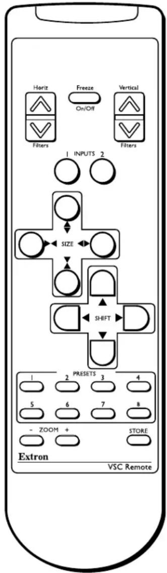
The optional VSC IR remote control, shown at right, replicates all of the front panel controls except the Menu and Next buttons. If Executive mode has been enabled on the VSC, input selection and adjustments can still be made from the remote control or the Windows-based control program (via an RS-232 device) to configure the video scan converter (see "Serial Communication" for details).
The topmost part of the remote control features the Horizontal filter buttons, a Freeze On and Off button, and the Vertical filter buttons.
Select input 1 or 2 via the Inputs buttons.
The middle portion of the VSC remote control features the Size and Shift buttons.
The bottom portion of the remote control features Presets 1 - 8. The presets save the input rate, the output type, sizing, shifting, and filtering information. After properly setting up an image, press the Store button, then press a preset button to save the settings to the selected preset button. To retrieve a preset, press the desired preset button.
Use the Zoom button to zoom in and zoom out of an image.
NOTE: The presets feature is only available through the IR remote control. For a detailed description of the other VSC features and functions that are accessed by the remote control, see earlier sections of this chapter.
text_image
Horiz Freeze Vertical Filters On/Off Filters 1 INPUTS 2 SIZE SHIFT PRESETS 3 4 5 6 7 8 - ZOOM + STORE Extron VSC RemoteSerial Communication
The VSC 500, 700, and 700D can be remotely controlled via a host computer or other device (such as a control system) attached to the rear panel RS-232/422 connector. The control device (host) can use either the Extron Simple Instruction Set (SISTM) commands or the graphical control program for Windows.
The video scan converter uses a protocol with:
9600 baud
- 1 stop bit
- no parity
- no flow control
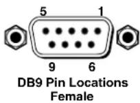
The rear panel RS-232/422 9-pin D connector has the following pin assignments:
| Pin | RS-232 function Description |
| 1 No | connection |
| 2 Tx | Transmit data |
| 3 Rx | Receive data |
| 4 Tx | 2 Transmit data |
| 5 Gnd | Signal ground |
| 6 No | connection |
| 7 No | connection |
| 8 Rx | 2 Receive data |
| 9 No | connection |
| Pin | RS-422 function Description |
| 1 No | connection |
| 2 Tx- | Transmit ground |
| 3 Rx- | Receive ground |
| 4 No | connection |
| 5 Gnd | Signal ground |
| 6 No | connection |
| 7 Rx+ | Receive data |
| 8 Tx | + Transmit data |
| 9 No | connection |
RS-232 Programming Guide
Host-to-VSC Communications
SIS commands consist of one or more characters per field. No special characters are required to begin or end a command sequence. When the VSC determines that a command is valid, it executes the command and sends a response to the host device. All responses from the VSC to the host end with a carriage return and a line feed (CR/LF = ←), which signals the end of the response character string. A string is one or more characters.
Video Scan Converter-initiated Messages
When a local event such as a front panel selection or adjustment takes place, the VSC responds by sending a message to the host. No response is required from the host. The VSC-initiated messages are listed here (underlined).
(C) Copyright 2002, Extron Electronics, VSC 500, Vx.xx ← The VSC sends the copyright message when it first powers on. Vx.xx is the firmware version number.
Error Responses
When the VSC receives a valid SIS command, it executes the command and sends a response to the host device. If the video scan converter is unable to execute the command because the command is invalid or it contains invalid parameters, it returns an error response to the host.
The error response codes and their descriptions are as follows:
• E01 – Invalid input channel number (the number is too large)
• E09 – Invalid function number (the number is too large)
• E10 – Invalid command
• E13 – Invalid value (the number is out of range/too large)
Using the Command and Response Tables
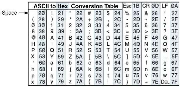
The command and response table lists valid command ASCII codes, the video scan converter's responses to the host, and a description of the command's function or the results of executing the command. Lower case characters are acceptable in the command field unless otherwise indicated. The following ASCII to HEX conversion table is for use with the command/response table.
Symbol Definitions
| X10 | = Picture adjustment range(see the note below) | ← = Carriage return (hex ∅D)● = Space |
| X11 | = Filter adjustment range (0 - 3) | X1 = Horizontal and vertical frequencies(listed to two decimal places, that is xx.xx) |
| X14 | = Adjustment range (0 - 127) | |
| Esc | = Escape key | |
| ← | = CR/LF (carriage return/line feed)(hex ∅D ∅A) | X2 = On/off status where: ∅ = off/disable, 1 = on/enable |
NOTE: The default value for horizontal and vertical size is 0512. The default values for the horizontal and vertical shift are 2048 and 1024, respectively. The actual minimum and maximum values will vary and are based on the incoming scan rate.
Command and Response Table for SIS Commands: VSC 500/700/700D
| Command Description ASCII Command Response Additional Description | |||
| Horizontal Shift | |||
| Specify the horizontalcentering value | X10 H Hph X10← | Specify the centering value | |
| Decrement one step | -H | Hph X10← | Shift left one step |
| Increment one step | +H | Hph X10← | Shift right one step |
| View the horizontal centeringvalue | H | X10← | Show the horizontal centeringvalue |
| Vertical Shift | |||
| Specify the vertical centeringvalue | X10 / Vph X10← | Specify the centering value | |
| Decrement one step | - / | Vph X10← | Shift down one step |
| Increment one step | + / | Vph X10← | Shift up one step |
| View the vertical centeringvalue | / | X10← | Show the vertical centering value |
| Horizontal Size | |||
| Specify the horizontal sizevalue | X10 : Hsz X10← | Specify the horizontal size value | |
| Decrease horizontal size onestep | - : | Hsz ← | Decrement the horizontal size |
| Increase horizontal size onestep | +: | Hsz ← | Increment the horizontal size |
| View the horizontal size value | : | X10← | Show the horizontal size value |
| Vertical Size | |||
| Specify the vertical size value | X10 ; Vsz X10← | Specify the vertical size value | |
| Decrease vertical size by onestep | - ; | Vsz ← | Decrement the vertical size |
| Increase vertical size by onestep | + ; | Vsz ← | Increment the vertical size |
| View the vertical size value | ; | X10← | Show the vertical size value |
| Zoom Mode | |||
| Zoom in | +{ | Zom ← | Zoom in |
| Zoom out | - { | Zom ← | Zoom out |
| Freeze Mode | |||
| Enable freeze mode | 1F | Frz 1← | Freeze the video output |
| Disable freeze mode | ∅F | Frz ∅← | Unfreeze the video output |
| View freeze mode status | F | X2← | Show freeze mode status (on = 1,off = 0) |
| Front Panel Security Lockout (executive mode) | |||
| Enable executive mode | 1X | Exe 1← | Lock front panel adjustments;adjust image via RS-232 only |
| Disable executive mode | ∅X | Exe ∅← | Unlock front panel adjustments |
| View executive mode status | X | X2← | Show executive mode status (on=1,off = 0) |
| Zap - Reset to Default Settings | |||
| System reset | Esc zXXX← | ZapXXX ← | Reset all settings to factory defaults |
| Firmware Version, Part Number and Information Requests | |||
| Query firmware version number | Q/q | x.xx← | Display firmware version |
| Request part number for VSC 500 | N/n | 60-476-01← | Display part # for VSC 500 |
| Request part number for VSC 700 | N/n | 60-477-01← | Display part # for VSC 700 |
| Request part number for VSC 700D | N/n | 60-477-02← | Display part # for VSC 700D |
| Request information | I/i← | HrtX1•VrtX1← | Display status of VSC |
Command and Response Table for SIS Commands: VSC 700/700D Only
| Command Description ASCII Command Response Additional Description | ||||
| Horizontal Filter (detail) | ||||
| Specify the horizontal filter value | 11 D Dhz 11 | Specify the detail value | ||
| Decrement one step | -D | Dhz 11 | Decrease the detail level by one step | |
| Increment one step | +D | Dhz 11 | Increase the detail level by one step | |
| View the horizontal filter value | D | 11 | Show the horizontal detail level | |
| Flicker Filter | ||||
| Specify the flicker filter value | 11 d Dvz 11 | Specify the flicker value | ||
| Decrement one step | -d | Dvz 11 | Decrease the flicker by one step | |
| Increment one step | +d | Dvz 11 | Increase the flicker by one step | |
| View the flicker filter value | d | 11 | Show the flicker value | |
Command and Response Table for Special Function SIS Commands: VSC 700/700D Only
The syntax for setting a special function is ! * _ # where _ is the function number and ! is the value. To view a function's setting, use _# where _ is the function number. In the following table the values of the ! variable are different for each command/function. These values are given in the rightmost column.
| Command Description ASCII Command Response Additional Description | |||
| Encoder Filter (sharpness) | |||
| Specify the encoder filter level | x! * 10# | Enc x!← | Specify the encoder filter level (0 - 3) |
| Example: | 3 * 10# | Enc 03← | Example: set the encoder filter level to 3 |
| View the encoder filter level | 10# | x!← | Show the encoder filter level |
Command and Response Table for Special Function SIS commands: VSC 500/700/700D
 | |||
 | |||
| Set the output video type | X! *6# Tpo X!← | Specify the output video type:0 = RGBHV (default)1 = RGBS2 = RGsB3 = YUV | |
| Example | 1* 6# | Tpo 1← | Example: specify output video as RGBS |
| View the output video type | 6# | X!← | View the output video type |
| Video Standard | |||
| Set the video standard | X! *14# Rte X!← | Select the output standard:0 = NTSC (default)1 = PAL | |
| Example: | 1*14# | Rte ← | Example: set output rate as PAL |
| View the video standard | 14# | X! ← | View the output standard |
| No Input Test Pattern | |||
| Set the output pattern when no input signal | X! *13# Out X!← | Specify the output pattern when no input0 = Black screen (default)1 = Color bars | |
| Example: | 1*13# | Out 1← | Example: specify color bars as the output when there is no input signal |
| View the output pattern when no input signal | 13# | X!← | View the output pattern when no input |
| Auto Imaging | |||
| Set the VSC to auto image | 55# | Img ← | Automatically center and size the image to fill the display screen. |
| Set the output video type | x! *6# Tpo x!← | Specify the output video type:0 = RGBHV (default)1 = RGBS2 = RGsB3 = YUV | |
| Example | 1* 6# | Tpo 1← | Example: specify output video as RGBS |
| View the output video type | 6# | x!← | View the output video type |
| Video Standard | |||
| Set the video standard | x! *14# Rte x!← | Select the output standard:0 = NTSC (default)1 = PAL | |
| Example: | 1*14# | Rte ← | Example: set output rate as PAL |
| View the video standard | 14# | x! ← | View the output standard |
| No Input Test Pattern | |||
| Set the output pattern when no input signal | x! *13# Out x!← | Specify the output pattern when no input0 = Black screen (default)1 = Color bars | |
| Example: | 1*13# | Out 1← | Example: specify color bars as the output when there is no input signal |
| View the output pattern when no input signal | 13# | x!← | View the output pattern when no input |
| Auto Imaging | |||
| Set the VSC to auto image | 55# | Img ← | Automatically center and size the image to fill the display screen. |
Control Software for Windows
The included control software for Windows offers another way to control the VSC via RS-232 connection in addition to the Simple Instruction Set commands. The graphical interface of the control program includes the same functions as those on the front panel of the VSC and some additional features that are only available through the Windows-based software
The minimum requirements for the PC:
- Windows ^ XP, Service Pack 2, Windows 7 or later
Intel® Pentium® II processor with a 400 MHz clock speed or faster
• At least 64 MB of RAM Device
• At least 10 MB of Hard Disk space
Installing the Program
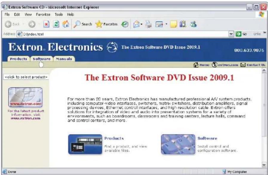
- Insert the DVD into the drive. The installation program should start automatically. The Extron software DVD window appears.
text_image
Extron Software CD - Microsoft Internet Explorer File Edit View Favorites Tools Help Back Search Favorites Go Links Address D:\index.html Extron® Electronics The Extron Software DVD Issue 2009.1 800.633.9076 Products Software Manuals Home extron.com Contact UsFigure 25. Extron Software Window
NOTE: If the installation program does not self-start, run Launch.exe from the DVD.
- Click the Software tab.
- Scroll to the VSC program and click Install.
- Follow the on-screen instructions. The installation program creates a C:\Program Files\Extron\VSC directory.
Using the Control Program
- To run the control program, double-click on the VSC program icon in the Extron Electronics group or folder. The Comm menu appears on the screen.
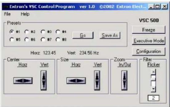
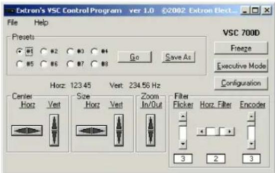
- Click on the comm port that is connected to the RS-232 port of the VSC. The Extron VSC Control Program window appears. The VSC 500 Control Program windo VSC 700D Control Program window are shown in the following figures.
text_image
Extron's VSC Control Program ver 1.0 ©2002 Extron Elect... File Help Presets #1 #2 #3 #4 Go Save As VSC 500 Freeze Executive Mode Configuration Horz: 123.45 Vert: 234.56 Hz Center Horz Vert Size Horz Vert Zoom In/Out Filter Flicker 2VSC Help
Figure 26. VSC 500 Control Program Window
text_image
Extron's VSC Control Program ver 1.0 ©2002 Extron Elect... File Help Presets W3 #2 #3 #4 Go Save As VSC 700D Freeze Executive Mode Configuration Horz 123.45 Vert 234.56 Hz Center Size Zoom Filter Horz Vert Horz Vert In/Out Flicker Hors. Filter Encoder 3 2 3Figure 27. VSC 700D Control Program Window
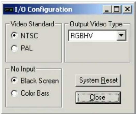
- Click on the Configuration button to configure the VSC from the I/O Configuration window, as shown in the next illustration.
text_image
I/O Configuration Video Standard NTSC PAL Output Video Type RGBHV No Input Black Screen Color Bars System Reset CloseFigure 28. VSC I/O Configuration window
Using the help program
For information on program features, press the
For explanations of buttons or functions, click on the tabs in the help screen to reach the desired screen. Use a mouse or the Tab and Enter keys to select a button or function. A description and tips on using the program will appear on screen.
Firmware Upgrade from the Extron Website
The firmware of the VSC 500, 700, or 700D may be upgraded by going to the Extron web site, downloading the latest firmware to the PC, then uploading and installing the new firmware from the PC to the VSC 500, 700, or 700D via the scan converter RS-232 port. The whole process takes only a few minutes and is very simple.
Downloading the Latest Firmware to the PC
Go to the Extron website (www.extron.com), select the product category, and download the latest firmware to your PC.
Uploading the firmware from the PC to the VSC
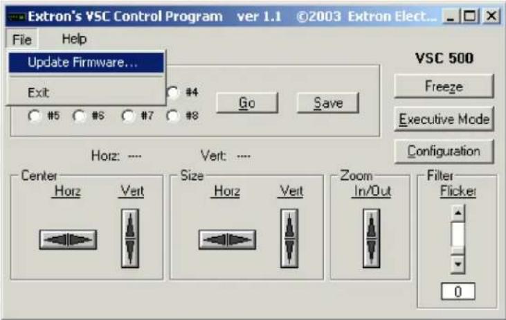
Connect the PC to the VSC 500, 700, or 700D via the RS-232 port of the scan converter. Start the control program (see the "Using the Control Program" section). Next, select Update Firmware from the Control Program window and follow the instructions.
text_image
Extron's VSC Control Program ver 1.1 ©2003 Extron Elect... File Help Update Firmware... Exit #4 Go Save #5 #6 #7 #8 VSC 500 Freeze Executive Mode Configuration Horz: .... Vert: .... Center Horz Veit Size Horz Veit Zoom In/Out Filter Flicker 0Figure 29. Update Firmware
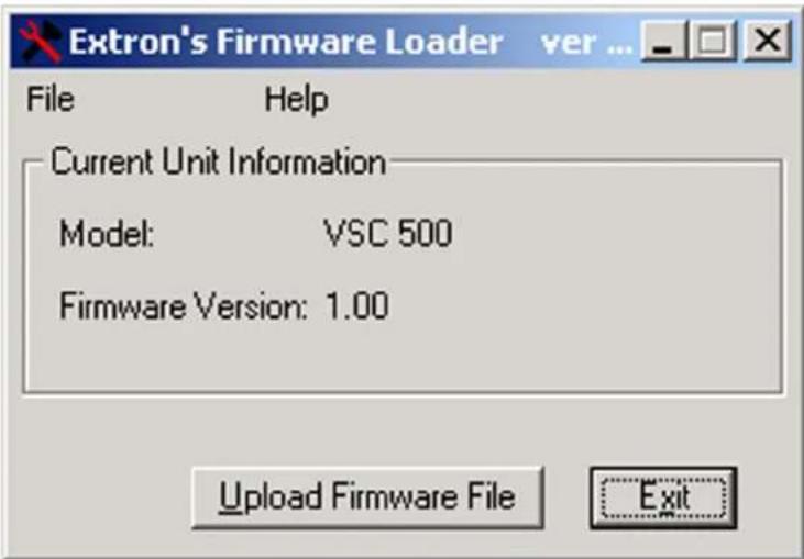
Select Upload Firmware File from the following window. The uploading of the firmware to the VSC 500, 700, or 700D will take a few minutes.
text_image
Extron's Firmware Loader ver ... File Help Current Unit Information Model: VSC 500 Firmware Version: 1.00 Upload Firmware File ExitFigure 30. Upload Firmware File
NOTE: The original factory-installed firmware is permanently available on the VSC 500, 700, or 700D. If the attempted upload of new firmware fails for any reason, the VSC will automatically revert to the factory-installed firmware.
Reference Information
Specifications: VSC 500
Video input
Number/signal type.... 1 RGBHV, RGBS, RGsB with 1 buffered loop-through Connectors .... (1) 15-pin HD for input, (1) 15-pin HD for loop-through Nominal level .... 0.7 Vp-p for RGB Minimum/maximum levels..... 0 V to 2.0 Vp-p with no offset at unity gain Impedance.... 75 ohms Horizontal frequency.... Autoscan 24 kHz to 100 kHz Vertical frequency.... Autoscan 50 Hz to 120 Hz Resolution range .... Autoscan 560 x 384 to 1920 x 1200; 480p, 720p, 1080i, 1080p (RGB only) Maximum DC offset .... 2.0 V
Video processing
Encoder.... 10 bit digital Digital sampling.... 24 bit, 8 bits per color Colors.... 16.8 million Horizontal filtering.... 1 fixed level Flicker filtering.... 4 levels (selectable) Encoder filtering.... 4 levels
Video output
Number/signal type.... 1 RGBHV, RGBS, RGsB, or component video 1 S-video, 1 composite video Connectors .... 5 BNC female: RGBHV/RGBS/RGsB/component video (1) 4-pin mini-DIN female: S-video 1 BNC female: composite video Nominal level .... 1 Vp-p for Y of component video and S-video, and for composite video 0.7 Vp-p for RGB and for R-Y and B-Y of component video 0.3 Vp-p for C of S-video Minimum/maximum levels.... 0.0 V to 0.7 Vp-p (RGB) 0.0 V to 1.0 Vp-p (component video, G of RGsB) Impedance.... 75 ohms
Sync
Input type.... Autodetect RGBHV, RGBS, RGsB Output type.... RGBHV, RGBS, RGsB Standards.... NTSC 3.58, PAL Input level .... 1.5 V to 5.0 Vp-p Output level .... TTL: 5.0 Vp-p, unterminated Input impedance .... 600 ohms
Output impedance.... 75 ohms
Max. input voltage.... 5.0 Vp-p
Polarity...... Negative
Control/remote — scan converter
Serial control port.... RS-232 or RS-422, 9-pin female D connector
Baud rate and protocol.... 9600 baud, 8 data bits, 1 stop bit, no parity
Serial control pin configurations
RS-232 2 = Tx, 3 = Rx, 5 = GND
RS-422 2 = Tx-, 3 = Rx-, 5 = GND, 7 = Rx+, 8 = Tx+
IR controller module...... VSC Remote
Program control.... Extron control/configuration program for Windows ^18
Extron Simple Instruction Set (SIS ^TM )
General
Power 100 VAC to 240 VAC, 50/60 Hz, 12 watts, internal
Temperature/humidity...... Storage -40° to +158°F (-40° to +70°C) / 10% to 90%, noncondensing
Operating +32° to +122°F (0° to +50°C) / 10% to 90%, noncondensing
Cooling ...... Convection, no vents
Mounting
Rack mount...... Yes, with optional 1U, 9.5" rack shelf, part #60-190-01 (RSU 129) or 60-604-01 (RSB 129)
Enclosure type ...... Metal
Enclosure dimensions.... 1.75" H x 8.75" W x 10.5" D (1U high, half rack wide)
(4.4 cm H x 22.2 cm W x 26.7 cm D)
(Depth excludes knobs.)
Product weight 2.4 lbs (1.1 kg)
Shipping weight 7 lbs (4 kg)
Vibration.... ISTA/NSTA 1A in carton (International Safe Transit Association)
Regulatory compliance
Safety...... CE, CUL, UL
EMI/EMC ...... CE, C-tick, FCC Class A, ICES, VCCI
Environmental...... Complies with the appropriate requirements of WEEE.
MTBF.... 30,000 hours
Warranty.... 3 years parts and labor
NOTES: • All nominal levels are at ±10%.
- Specifications are subject to change without notice.
Specifications: VSC 700 and 700D
Video input
Number/signal type.... 1 RGBHV, RGBS, RGsB with 1 buffered loop-through
Connectors 2 x 5 female BNC (5 for input, 5 for loop-through)
Nominal level 0.7 Vp-p for RGB
Minimum/maximum levels..... 0 V to 2.0 Vp-p with no offset at unity gain
Impedance 75 ohms
Horizontal frequency.... Autoscan 24 kHz to 100 kHz
Vertical frequency.... Autoscan 50 Hz to 120 Hz
Resolution range ...... Autoscan 560 x 384 to 1920 x 1200; 480p, 720p, 1080i, 1080p (RGB only)
DC offset (max. allowable)..... 2.0 V
External sync (genlock) 0.3 V to 1.0 Vp-p
Video processing
Encoder.... 10 bit digital
Digital sampling.... 24 bit, 8 bits per color
Colors.... 16.8 million
Horizontal filtering 4 levels
Flicker filtering 4 levels
Encoder filtering...... 4 levels
Video output
Number/signal type.... 1 RGBHV, RGBS, RGsB, or component video
1 SDI component video (VSC 700D only)
1 S-video
1 NTSC/PAL composite video
Connectors 5 BNC female: RGBHV/RGBS/RGsB/component video
1 BNC female: SDI component video (VSC 700D only)
(1) 4-pin mini-DIN female: S-video
1 BNC female: composite video
Nominal level 1 Vp-p for Y of component video and S-video, and for composite video
0.7 Vp-p for RGB and for R-Y and B-Y of component video
0.3 Vp-p for C of S-video
Minimum/maximum levels..... 0.0 V to 0.7 Vp-p (RGB)
0.0 V to 1.0 Vp-p (component video, G of RGsB)
Impedance 75 ohms
Sync
Input type.... Autodetect RGBHV, RGBS, RGsB
Output type...... RGBHV, RGBS, RGsB
Genlock connectors.... 1 BNC female: genlock input
1 BNC female: genlock output (terminate w/75 ohms if unused)
Standards.... NTSC 3.58, PAL
Input level 1.5 V to 5.0V p-p
Output level.... TTL: 5.0V p-p, unterminated
Input impedance 600 ohms
Output impedance 75 ohms
Max. input voltage.... 5.0 Vp-p
Polarity...... Negative
Control/remote — scan converter
Serial control port.... RS-232 or RS-422, 9-pin female D connector
Baud rate and protocol.... 9600 baud, 8 data bits, 1 stop bit, no parity
Serial control pin configurations. RS-232: 2 = Tx, 3 = Rx, 5 = GND
RS-422: 2 = Tx-, 3 = Rx-, 5 = GND, 7 = Rx+, 8 = Tx+
IR controller module...... VSC Remote
Program control...... Extron control/configuration program for Windows ^®
Extron Simple Instruction Set (SIS ^TM )
General
Power 100 VAC to 240 VAC, 50/60 Hz, 12 watts, internal
Temperature/humidity...... Storage: -40 to +158 °F (-40 to +70 °C) / 10% to 90%, noncondensing
Operating: +32 to +122 °F (0 to +50 °C) / 10% to 90%, noncondensing
Cooling ...... Convection, no vents
Mounting
| Rack mount...... | Yes, with optional 1U, 9.5" deep rack shelf, part # 60-190-01 (RSU 129) or 60-604-01 (RSB 129) |
| Enclosure type...... | Metal |
| Enclosure dimensions | |
| VSC 700...... | 1.75" H x 8.75" W x 10.5" D (1U high, half rack wide)(4.4 cm H x 22.2 cm W x 26.7 cm D)(Depth excludes knobs.) |
| VSC 700D...... | 1.75" H x 8.75" W x 10.75" D (1U high, half rack wide)(4.4 cm H x 22.2 cm W x 27.3 cm D)(Depth excludes knobs.) |
| Product weight | |
| VSC 700...... | 2.8 lbs (1.3 kg) |
| VSC 700D...... | 2.9 lbs (1.3 kg) |
| Shipping weight...... | 5 lbs (3 kg) |
| Vibration...... | ISTA 1A in carton (International Safe Transit Association) |
| Regulatory compliance | |
| Safety...... | CE, CUL, UL |
| EMI/EMC...... | CE, C-tick, FCC Class A, ICES, VCCI |
| Environmental...... | Complies with the appropriate requirements of WEEE. |
| MTBF...... | 30,000 hours |
| Warranty...... | 3 years parts and labor |
NOTES: • All nominal levels are at ±10%.
- Specifications are subject to change without notice.
Included Parts
These items are included in each order for a VSC 500, 700, or 700D:
| Included Parts Part Number to Reorder | |
| VSC 500 60-476-01 | |
| or VSC 700 60-477-01 | |
| or VSC 700D 60-477-02 | |
| Rubber feet (not attached) | |
| SDI output board (700D only) 70-065-02 | |
| VSC 500/700/700D Setup Guide |
Accessories
| Accessories Part Number | |
| 1U high, 9.5" universal rack shelf | 60-190-01 |
| VSC IR remote control 70-206-01 | |
Firmware Upgrade Chip Installation
In some cases the VSC firmware may require replacement with an updated version. There is one user-replaceable firmware chip: U29 — the main microcon troller. The number is printed on the circuit board. We recommend that you send the unit in to Extron for service and updates.
WARNING: Changes to firmware must be performed by authorized service personnel only.
Follow these steps to replace firmware in the VSC.
- Disconnect the AC power cord from the VSC to remove power from the unit.
WARNING: To prevent electric shock, always unplug the VSC video scan converter from the AC power source before opening the enclosure.
Remove the scan converter from the rack or furniture.
- Remove the cover of the VSC (the top half of the enclosure) by removing the screws, sliding the cover back, then lifting the cover straight up.
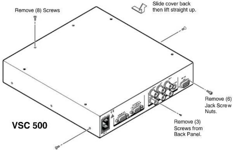
text_image
Remove (8) Screws Slide cover back then lift straight up. VSC 500 Remove (6) Jack Screw Nuts. Remove (3) Screws from Back Panel.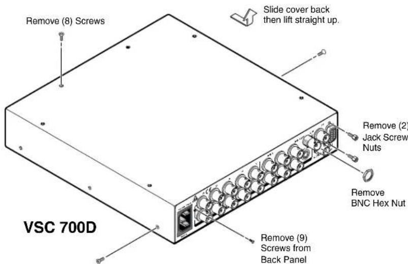
text_image
Remove (8) Screws Slide cover back then lift straight up. Remove (2) Jack Screw Nuts Remove BNC Hex Nut Remove (9) Screws from Back Panel VSC 700DFigure 31. Top Cover Removal
- Locate the U29 firmware chip to be replaced on the circuit board, as shown in the following illustrations.
CAUTION: Do not touch any switches or other electronic components inside the VSC. Doing so could damage the video scan converter. Electrostatic discharge (ESD) can damage IC chips even though you cannot feel it. You must be electrically grounded before proceeding with firmware replacement. A grounding wrist strap is recommended.
- After you are electrically grounded, removal of the U29 IC chip requires a PLCC IC puller tool. To remove the U29 chip, align the hooks of a PLCC IC puller tool with the slots located in opposite ends of the firmware chip.
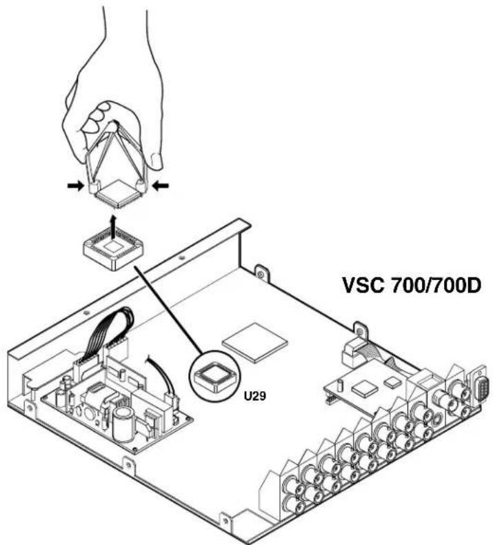
text_image
VSC 700/700D U29Figure 32. Chip Removal
- Insert the hooks into the slots, and squeeze the tool gently to grasp the chip.
- Pull the chip straight out of the socket, and set it aside.
- Align the slots of the new firmware chip with the angled corners of the socket in the same orientation as the old chip.
- Gently, but firmly, press the chip into place in the socket.
- Replace the top cover and secure it with the screws removed in step 2.
Mounting the VSC
Select tabletop placement or rack mounting. Follow the appropriate installation instructions on the following pages.
Tabletop or Desktop Placement
For tabletop or desktop placement only, install the self-adhesive rubber feet/pads (provided) onto the four corners of the bottom of the enclosure.
Rack Mounting
Underwriters Laboratories Guidelines for Rack Mounting
The following Underwriters Laboratories (UL) guidelines are relevant to the safe installation of these products in a rack:
Elevated operating ambient temperature — If the unit is installed in a closed or multi-unit rack assembly, the operating ambient temperature of the rack environment may be greater than room ambient temperature. Therefore, install the equipment in an environment compatible with the maximum ambient temperature (Tma: +122 °F, +50 °C) specified by Extron.
Reduced air flow — Install the equipment in the rack so that the equipment gets adequate air flow for safe operation.
Mechanical loading — Mount the equipment in the rack so that uneven mechanical loading does not create a hazardous condition.
Circuit overloading — Connect the equipment to the supply circuit and consider the effect that circuit overloading might have on overcurrent protection and supply wiring. Give appropriate consideration to the equipment nameplate ratings when addressing this concern.
Reliable earthing (grounding) — Maintain reliable grounding of rack-mounted equipment. Pay particular attention to supply connections other than direct connections to the branch circuit (such as the use of power strips).
Rack mounting procedure
-
If feet were installed on the bottom of the VSC, remove them.
-
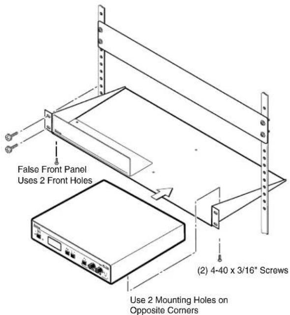
Place the scan converter on one half of the 1U (one unit high, one unit wide) rack shelf (part number 60-190-01). Align the front of the VSC with the front of the shelf, and align the threaded holes on the bottom of the VSC 500/700 with the holes in the rack shelf.
-
Attach the VSC to the rack shelf with the two provided 4-40 x 1/8 inch machine screws. Insert the screws from the underside of the shelf, and securely fasten them into diagonally opposite corners, as shown in the following illustration.
text_image
False Front Panel Uses 2 Front Holes Use 2 Mounting Holes on Opposite Corners (2) 4-40 x 3/16" ScrewsFigure 33. Rack Shelf Mounting
-
Attach the false front panel (provided with the rack shelf) to the unoccupied side of the rack (as shown above), or install a second half-rack width device in that side by repeating steps 1 - 3.
-
Attach the rack shelf to the rack using four 10-32 x 34 inch bolts (provided). Insert the bolts through #10 beveled washers, then through the holes in the rack ears and rack, as shown above.
Extron® Warranty
Extron Electronics warrants this product against defects in materials and workmanship for a period of three years from the date of purchase. In the event of malfunction during the warranty period attributable directly to faulty workmanship and/or materials, Extron Electronics will, at its option, repair or replace said products or components, to whatever extent it shall deem necessary to restore said product to proper operating condition, provided that it is returned within the warranty period, with proof of purchase and description of malfunction to:
USA, Canada, South America, and Central America:
Extron Electronics
1001 East Ball Road
Anaheim, CA 92805
U.S.A.
Japan:
Extron Electronics, Japan
Kyodo Building, 16 Ichibancho
Chiyoda-ku, Tokyo 102-0082
Japan
Europe, Africa, and the Middle East:
Extron Europe
Hanzeboulevard 10
3825 PH Amersfoort
The Netherlands
China:
Extron China
686 Ronghua Road
Songjiang District
Shanghai 201611
China
Asia:
Extron Asia
135 Joo Seng Road, #04-01
PM Industrial Bldg
Singapore 368363
Singapore
Middle East:
Extron Middle East
Dubai Airport Free Zone
F12, PO Box 293666
United Arab Emirates, Dubai
This Limited Warranty does not apply if the fault has been caused by misuse, improper handling care, electrical or mechanical abuse, abnormal operating conditions, or modifications were made to the product that were not authorized by Extron.
NOTE: If a product is defective, please call Extron and ask for an Application Engineer to receive an RA (Return Authorization) number. This will begin the repair process.
USA: (714) 491-1500
Europe: 31.33.453.4040
Asia: 65.6383.4400
81.3.3511.7655
Units must be returned insured, with shipping charges prepaid. If not insured, you assume the risk of loss or damage during shipment. Returned units must include the serial number and a description of the problem, as well as the name of the person to contact in case there are any questions.
Extron Electronics makes no further warranties either expressed or implied with respect to the product and its quality, performance, merchantability, or fitness for any particular use. In no event will Extron Electronics be liable for direct, indirect, or consequential damages resulting from any defect in this product even if Extron Electronics has been advised of such damage.
Please note that laws vary from state to state and country to country, and that some provisions of this warranty may not apply to you.
| Extron USA - West Headquarters | Extron USA - East | Extron Europe | Extron Asia | Extron Japan | Extron China | Extron Middle East |
| +800.633.9876Inside USA/Canada Only | +800.633.9876Inside USA/Canada Only | +800.3987.6673Inside Europe Only | +800.7339.8766Inside Asia Only | +81.3.3511.7655+81.3.3511.7656 FAX | +400.883.1568Inside China Only | +971.4.2991800+971.4.2991880 FAX |
| +1.714.491.1500+1.714.491.1517 FAX | +1.919.863.1794+1.919.863.1797 FAX | +31.33.453.4040+31.33.453.4050 FAX | +65.6383.4400+65.6383.4664 FAX | +86.21.3760.1568+86.21.3760.1566 FAX |