
TZT14 - Uncategorized FURUNO - Free user manual and instructions
Find the device manual for free TZT14 FURUNO in PDF.


User questions about TZT14 FURUNO
0 question about this device. Answer the ones you know or ask your own.
Ask a new question about this device
Download the instructions for your Uncategorized in PDF format for free! Find your manual TZT14 - FURUNO and take your electronic device back in hand. On this page are published all the documents necessary for the use of your device. TZT14 by FURUNO.
USER MANUAL TZT14 FURUNO
SAFETY INSTRUCTIONS .... i
SYSTEM CONFIGURATION ....ii
EQUIPMENT LISTS......iii
1. MOUNTING....1-1
1.1 Mounting Considerations 1-1
1.2 Flush Mounting 1-2
1.3 Desktop Mounting....1-4
2. WIRING....2-1
2.1 Wiring Instructions 2-1
2.2 CAN bus/NMEA0183 Data Conversion and CAN bus Bridging....2-8
2.3 Example NavNet TZtouch System Configurations....2-11
3. SETTING UP THE EQUIPMENT 3-1
3.1 How to Set Time Zone, Language and Units....3-3
3.2 Menu Initial Setup 3-5
3.3 How to Set up the Radar....3-8
3.4 How to Set up the Sounder....3-11
3.5 Wireless LAN Setting 3-13
PACKING LISTS ...... A-1
OUTLINE DRAWINGS ...... D-1
INTERCONNECTION DIAGRAM S-1
NAVnet
TZ touch
FURUNO ELECTRIC CO., LTD.
www.furuno.com
All brand and product names are trademarks, registered trademarks or service marks of their respective holders.
The installer must read the appropriate safety instructions before attempting to install the equipment.

WARNING
Indicates a potentially hazardous situation which, if not avoided, could result in death or serious injury.

CAUTION
Indicates a potentially hazardous situation which, if not avoided, may result in minor or moderate injury.
(Examples of symbols)

Warning, Caution Prohibitive Action Mandatory Action


WARNING

ELECTRICAL SHOCK HAZARD Do not open the equipment unless totally familiar with electrical circuits.
Only qualified personnel should work inside the equipment.

Turn off the power at the switchboard before beginning the installation.
Fire or electrical shock can result if the power is left on.

Be sure that the power supply is compatible with the voltage rating of the equipment.
Connection of an incorrect power supply can cause fire or damage the equipment.

CAUTION

Ground the equipment to prevent electrical shock and mutual interference.

Use the proper fuse.
Use of an incorrect fuse may damage the equipment.

The front panel is made of glass. Handle it with care.
Injury can result if the glass breaks.
Observe the following compass safe distances to prevent interference to a magnetic compass:
| Standard compass | Steering compass | |
| TZT9 | 0.50 m | 0.30 m |
| TZT14 | 0.64 m 0 | .40 m |
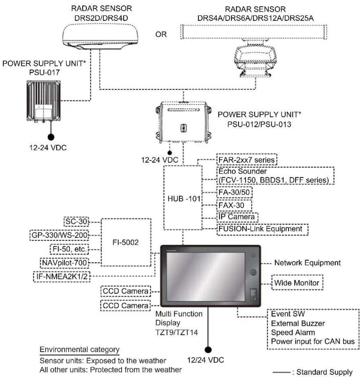
flowchart
graph TD
    A["RADAR SENSOR DRS2D/DRS4D"] --> B["POWER SUPPLY UNIT* PSU-017"]
    C["RADAR SENSOR DRS4A/DRS6A/DRS12A/DRS25A"] --> D["POWER SUPPLY UNIT* PSU-012/PSU-013"]
    B --> E["12-24 VDC"]
    D --> F["HUB -101"]
    F --> G["FAR-2xx7 series"]
    F --> H["Echo Sounder (FCV-1150, BBDS1, DFF series)"]
    F --> I["FA-30/50"]
    F --> J["FAX-30"]
    F --> K["IP Camera"]
    F --> L["FUSION-Link Equipment"]
    M["FI-5002"] --> N["Multi Function Display TZT9/TZT14"]
    O["SC-30"] --> P["FI-5002"]
    Q["GP-330/WS-200"] --> R["FI-5002"]
    S["FI-50, etc."] --> T["FI-5002"]
    U["NAVpilot-700"] --> V["FI-5002"]
    W["IF-NMEA2K1/2"] --> X["FI-5002"]
    Y["CCD Camera"] --> Z["Multi Function Display TZT9/TZT14"]
    AA["CCD Camera"] --> AB["Multi Function Display TZT9/TZT14"]
    AC["Network Equipment"] --> AD["Multi Function Display TZT9/TZT14"]
    AE["Wide Monitor"] --> AF["Multi Function Display TZT9/TZT14"]
    AG["Event SW"] --> AH["Multi Function Display TZT9/TZT14"]
    AI["External Buzzer"] --> AJ["Multi Function Display TZT9/TZT14"]
    AK["Speed Alarm"] --> AL["Multi Function Display TZT9/TZT14"]
    AM["Power input for CAN bus"] --> AN["Multi Function Display TZT9/TZT14"]
    AO["Environmental category"] --> AP["Sensor units: Exposed to the weather"]
    AO --> AQ["All other units: Protected from the weather"]
    AR["12/24 VDC"] --> AS["Multi Function Display TZT9/TZT14"]
*: The power supply unit is required when you connect the radar sensor.
PSU-012: w/DRS2D/4D/4A/6A/12A
PSU-013: w/DRS25A
PSU-017: w/DRS2D/4D
For details of the power supply unit, see the installation manual of the radar sensor (IME-35670).
Standard supply
| Name Type Code No. Qty Remarks | ||||
| Multi Function Display | TZT9 - | 1 | ||
| TZT14 - | ||||
| Installation Materials | CP19-01500 | 000-020-450 | 1 For TZT9 | |
| 000-022-431 | ||||
| CP19-01600 | 000-020-451 | 1 For TZT14 | ||
| 000-022-432 | ||||
| Accessories | FP19-01700 | 000-022-620 | 1 For TZT9 | |
| 000-022-621 | ||||
| FP19-01900 | 000-022-622 | 1 For TZT14 | ||
| 000-022-623 | ||||
| Spare Parts | SP19-01301 | 001-175-310 | 1 Fuses (for TZT9) | |
| 001-201-370 | ||||
| SP19-01201 | 001-166-210 | 1 Fuses (for TZT14) | ||
| 001-201-420 | ||||
Optional supply
| Name Type Code No. Remarks | |||
| Joint Box TL-CAT-012 000-016-714-01 For LAN network | |||
| NMEA2000-Interface Unit | IF-NMEA2K1 - | ||
| NMEA Data Converter | IF-NMEA2K2 - | ||
| Network HUB | HUB-101 | - | |
| Junction Box | FI-5002 | - | |
| Rectifier | RU-3423 | 000-030-443 | |
| PR-62 | 000-013-484 | 100VAC | |
| 000-013-485 | 110VAC | ||
| 000-013-486 | 220VAC | ||
| 000-013-487 | 230VAC | ||
| RU-1746B-2 000-030-439 | |||
| CAN bus Cable Assy | M12-05BM+05BF-010 | 001-105-750-10 | w/connectors (light), 1 m |
| M12-05BM+05BF-020 | 001-105-760-10 w | connectors (light), 2 m | |
| M12-05BM+05BF-060 | 001-105-770-10 w | connectors (light), 6 m | |
| M12-05BFFM-010 | 001-105-780-10 w | connector (light), 1 m | |
| M12-05BFFM-020 | 001-105-790-10 w | connector (light), 2 m | |
| M12-05BFFM-060 | 001-105-800-10 w | connector (light), 6 m | |
| CB-05PM+05BF-010 | 000-167-968-10 w | connectors (heavy), 1 m | |
| CB-05PM+05BF-020 | 000-167-968-10 w | connectors (heavy), 2 m | |
| CB-05PM+05BF-060 | 000-167-970-10 w | connectors (heavy), 6 m | |
| CB-05BFFM-010 | 000-167-971-10 | w/connector (heavy), 1 m | |
| CB-05BFFM-020 | 000-167-972-10 | w/connector (heavy), 2 m | |
| CB-05BFFM-060 | 000-167-973-10 | w/connector (heavy), 6 m | |
| Name | Type | Code No. | Remarks |
| DVI-D Cable Assy. DVI- | D/D S-LINK 5M 001-132-9 | 60-10 24 pin, for video output, 5 m | |
| DVI-D/D S-LINK 10M 001- | 133-980-10 24 pin, for video output, 10 m | ||
| External Buzzer OP03- | 136 000-086-443 Buzzer: P | KB5-3A40 | |
| Replacement Kit OP19- | 9 001-233-680 For TZT9 | ||
| OP19-10 001-233-690 | |||
| OP19-11 001-233-700 For TZT14 | |||
| OP19-12 001-233-710 | |||
| Network (LAN) Cable | MOD-Z073-030+ 000-167 | -171-10 | LAN cable, straight, 2 pairs, 3 m |
| MOD-Z072-020+ 001-167 | -880-10 LAN cable, cross-pair, 2 m | ||
| MOD-Z072-050+ 001-167 | -890-10 LAN cable, cross-pair, 5 m | ||
| MOD-Z072-100+ 001-167 | -900-10 LAN cable, cross-pair, 10 m | ||
| CAN bus Connector SS | -050505-FMF-TS001 000- | 168-603-10 Micro style: 3 | |
| NC-050505-FMF-TS001 | 000-160-807-10 Mini style: 2, micro style: 1 | ||
| LTWMC-05BMMT-SL8001 | 000-168-604-10 | Micro style, male, termination resistor | |
| LTWMN-05AMMT-SL8001 | 000-160-508-10 | Mini style, male, termination resistor | |
| LTWMC-05BFFT-SL8001 | 000-168-605-10 | Micro style, female, termination resistor | |
| LTWMN-05AFFT-SL8001 | 000-160-509-10 | Mini style, female, termination resistor | |
| FRU-0505-FF-IS | 001-077-830-10 w/inline terminator | ||
| MJ Cable Assy | MJ-A6SPF0016-005C | 000-159-689-10 for FAX-30 | |
| Operator's Manual | OME-44700-* | 000-176-016-1* | English |
| OMJ-44700-* | 000-176-015-1* | Japanese | |
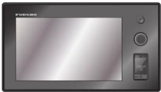
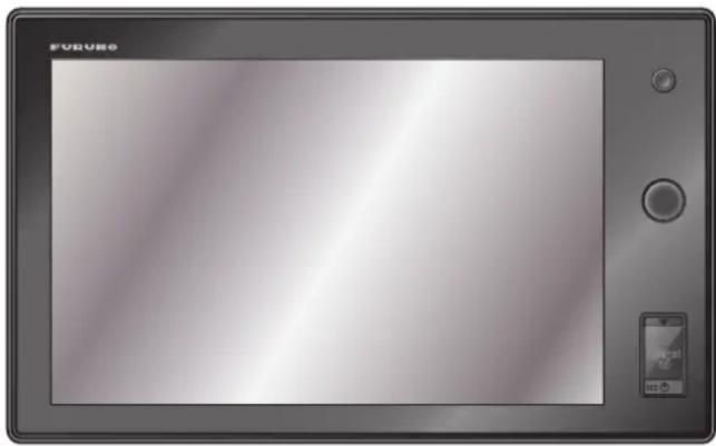
1.1 Mounting Considerations
natural_image
Front view of a digital camera with a screen and control panel (no visible text or symbols)TZT9
natural_image
Front view of a digital tablet device with control buttons and a small screen (no visible text or symbols)TZT14
When selecting a mounting location for TZT9/14, keep the following in mind:
- The temperature at the mounting location shall be between -15^ and +55^ (wireless LAN: 0^ and +55^ ).
- The humidity at the mounting location shall be 93% or less at 40°C.
- Locate the unit away from exhaust pipes and ventilators.
- The mounting location should be well ventilated.
- Mount the unit where shock and vibration are minimal (comply with IEC 60945 Ed.4).
- Keep the unit away from electromagnetic field generating equipment such as motors and generators.
- For maintenance and checking purposes, leave sufficient space around the unit and leave slack in cables. Minimum recommended space is shown in the outline drawing for the display units.
- Do not mount the TZT9/14 on the overhead.
- A magnetic compass will be affected if the equipment is placed too close to it. Observe the compass safe distances shown in the SAFETY INSTRUCTIONS to prevent disturbance to the magnetic compass.
The TZT9/14 can be flush mounted in a console or panel, or mounted on a desktop.
When removing the equipment
If the equipment is removed from the vessel, cover the connector of the cable with the supplied cap to keep dust out of the connector.
1. MOUNTING
1.2 Flush Mounting
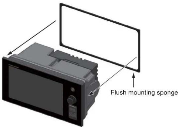
Select a flat mounting location and install the unit as shown below.
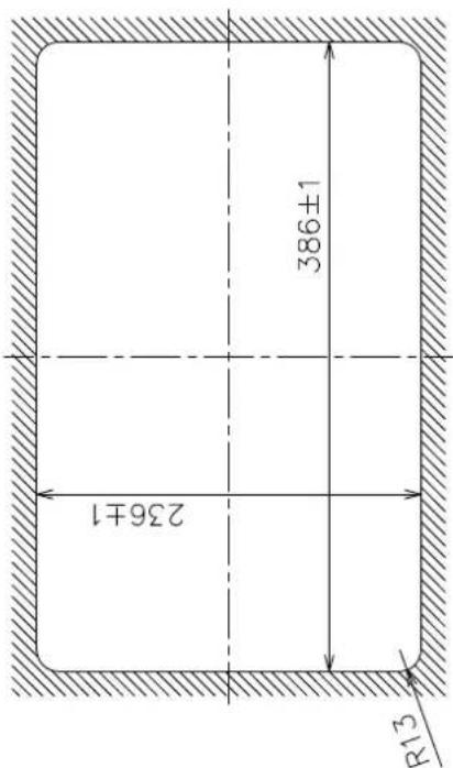
- Prepare a cutout in the mounting location using the template (supplied) for the TZT9 or TZT14.
- Attach the flush mounting sponge (supplied as installation materials) to the back of the TZT9/14.
text_image
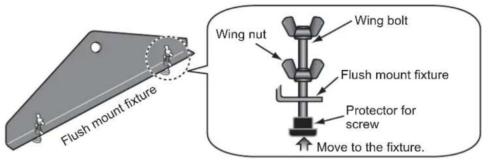
Flush mounting sponge- Screw the wing bolts and the wing nuts of the flush mount fixture so that the protector for screw moves to the flush mount fixture.
text_image
Flush mount fixture Wing nut Wing bolt Flush mount fixture Protector for screw Move to the fixture.-
Connect all cables at the back of the TZT9/14. (See chapter 2.)
-
Set the TZT9/14 to the cutout.
-
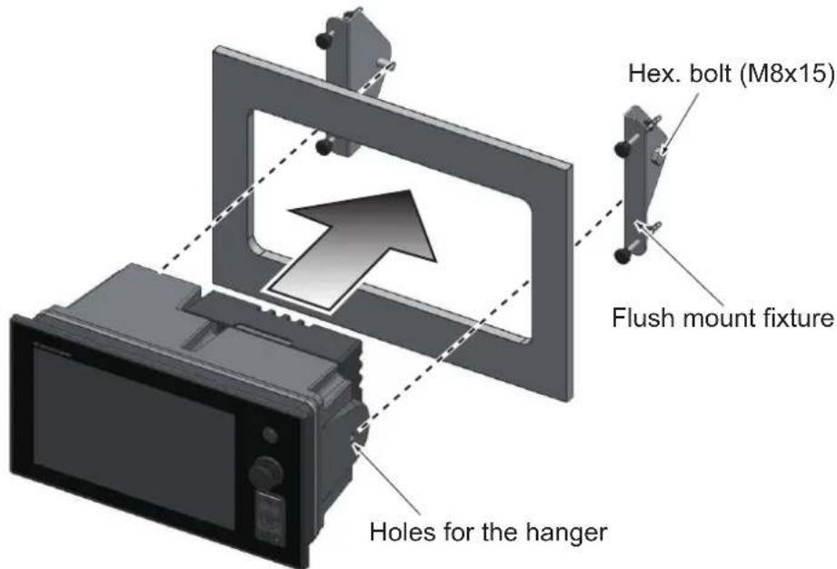
Fasten the flush mount fixtures to the holes for the hanger at both sides of TZT9/14 with two hex. bolts (M8x15, supplied).
text_image
Hex. bolt (M8x15) Flush mount fixture Holes for the hanger-
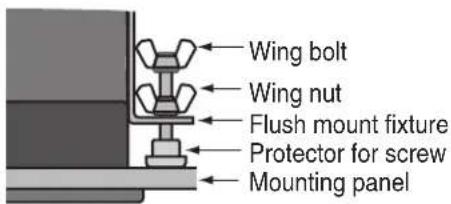
Fasten each wing bolt so that the protector for screw touches the mounting panel.
-
Fasten the wing nuts tightly.
text_image
Wing bolt Wing nut Flush mount fixture Protector for screw Mounting panelTZT9/14 with a fixing panel, top view
1. MOUNTING
1.3 Desktop Mounting
Follow the procedure below to mount the TZT9 or TZT14 on a desktop.
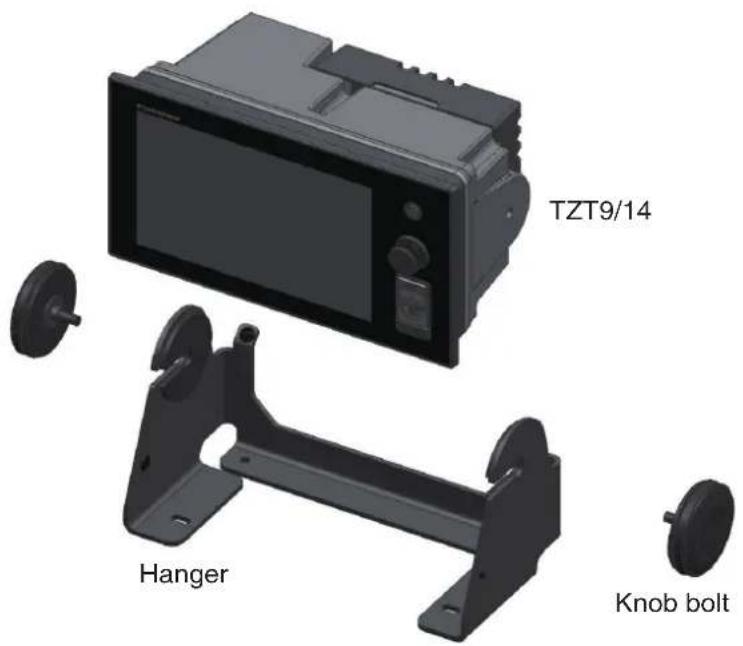
- Fix the hanger by using self-tapping screws (supplied).
- Screw knob bolts into the TZT9/14, set the unit to the hanger and tighten the knob bolts.
text_image
TZT9/14 Hanger Knob bolt2.1 Wiring Instructions
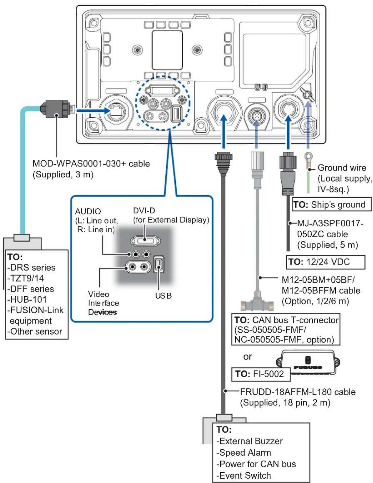
TZT9
text_image
MOD-WPAS0001-030+ cable (Supplied, 3 m) AUDIO (L: Line out, R: Line in) DVI-D (for External Display) Video Interface Devices USB Ground wire (Local supply, IV-8sq.) TO: Ship's ground MJ-A3SPF0017- 050ZC cable (Supplied, 5 m) TO: 12/24 VDC M12-05BM+05BF/ M12-05BFFM cable (Option, 1/2/6 m) TO: CAN bus T-connector (SS-050505-FMF/ NC-050505-FMF, option) or TO: FI-5002 FRUDD-18AFFM-L180 cable (Supplied, 18 pin, 2 m) TO: -External Buzzer -Speed Alarm -Power for CAN bus -Event SwitchTZT14
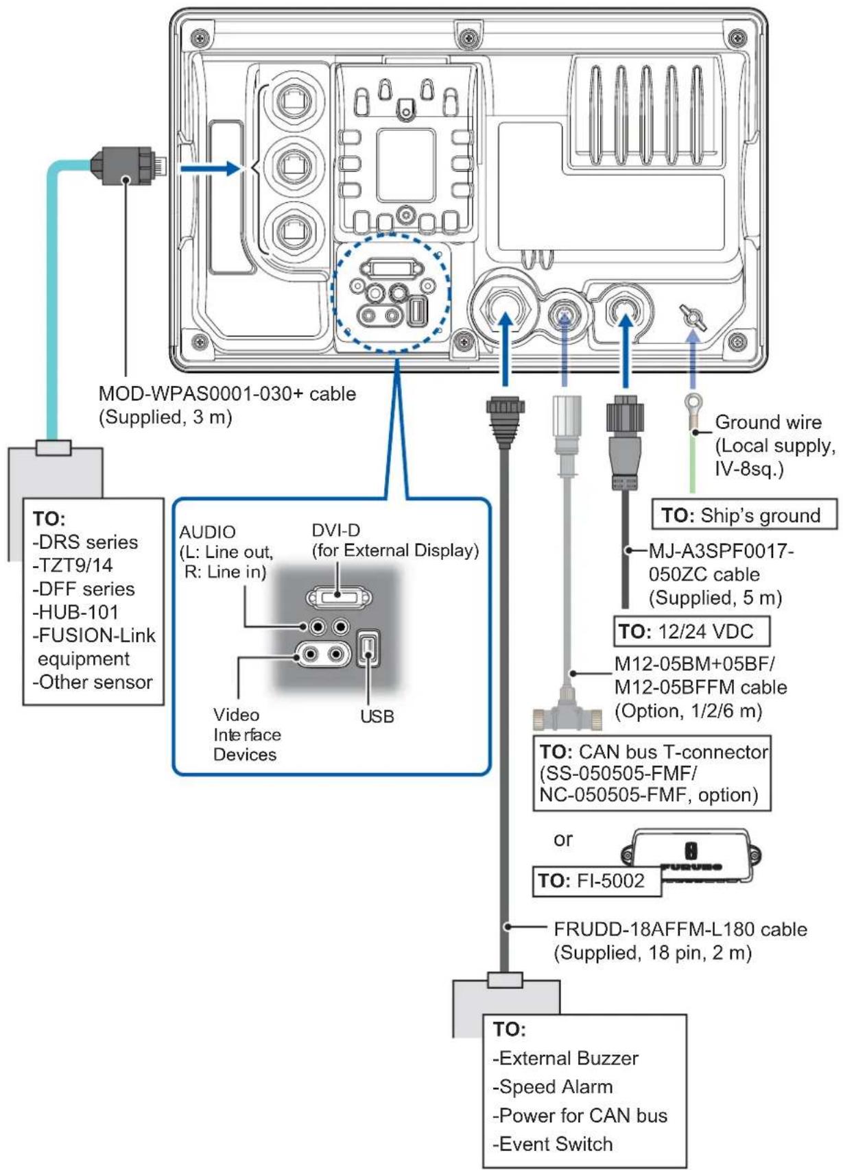
text_image
MOD-WPAS0001-030+ cable (Supplied, 3 m) TO: -DRS series -TZT9/14 -DFF series -HUB-101 -FUSION-Link equipment -Other sensor AUDIO (L: Line out, R: Line in) DVI-D (for External Display) Video Interface Devices USB Ground wire (Local supply, IV-8sq.) TO: Ship's ground MJ-A3SPF0017- 050ZC cable (Supplied, 5 m) TO: 12/24 VDC M12-05BM+05BF/ M12-05BFFM cable (Option, 1/2/6 m) TO: CAN bus T-connector (SS-050505-FMF/ NC-050505-FMF, option) or TO: FI-5002 FRUDD-18AFFM-L180 cable (Supplied, 18 pin, 2 m) TO: -External Buzzer -Speed Alarm -Power for CAN bus -Event Switch2.1.1 NETWORK port(s)
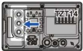
TZT9/14 (just like previous NavNets) uses standard TCP/IP Ethernet to share radar/sounder images and other navigation information from de-

text_image
TZT14vices connected within the network system. In any single NavNet TZtouch network, a combination of up to six TZT9/14 may be connected to each other. All NavNet TZ-touch network components have integrated regular RJ45 Ethernet port(s), one on TZT9 and three on TZT14. Connect MOD-WPAS0001-030+ cable (supplied).
2.1.2 MULTI port
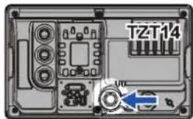
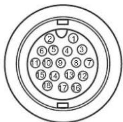
Use the cable assembly FRUDD-18AFFM-L180 (supplied, 2 m) for the event switch, external buzzer, speed alarm and the power for CAN bus.

text_image
TZT14 VITThis cable has an 18-pin connector. For example, a MOB contact closure input may be connected to pin 15 and 11*.
*Note that any TZT9/14 interfaces to virtually any MOB system or event switch (point save) contact closure signal using these pins.
text_image
② ① 6 5 4 3 11 10 9 8 7 15 14 13 12 18 17 16| Pin No. | Color Function Remark (Port No.) | ||
| 18 Light green NET-C IN (0V) CAN bus Power IN. When 12V DC power is applied to these pins, the CAN bus port will be powered (up to 1 ampere). | |||
| 17 Pink | NET-S IN (+12V IN) | ||
| 16 Purple Shield | |||
| 15 White BUZZER or EVENT IN | External Buzzer Output or MOB/Event Input (Contact Closure) | ||
| 14 Gray SPEED-ALARM C Speed alarm contact. Can trigger an external alarm or device when speed exceeds the limit specified. | |||
| 13 Yellow SPEED-ALARM H | |||
| 12 Black/White +12V External buzzer power ONLY (100mA Max) | |||
| 11 Black GND GND for Event/MOB Input | |||
| 10 Blue/White - For debug | |||
| 9 | Blue | - | |
| 8 | Green/White | - | |
| 7 | Green | - | |
| 6 | Orange/White | - | |
| 5 | Orange | GND | |
| 4 | Brown/White | DC_N | |
| 3 | Brown | PWR_SW | |
| 2 | Red/White | GND | |
| 1 | Red | GND | |
2. WIRING
2.1.3 CAN bus port
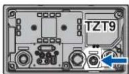
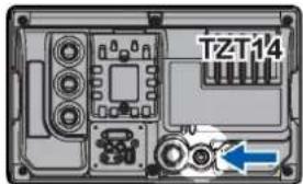
Every TZT9/14 has one CAN bus port (micro style connector). All TZT9/14 MUST be connected to the same CAN bus backbone. However, the TZT9/14 and DRS (radar sensor) CAN bus ports
text_image
TZT14cannot be connected together. The TZT9/14 and DRS (radar sensor) use “Ethernet Bridging” to link the DRS CAN bus and the TZT9/14 CAN bus data. Refer to paragraph 2.2.1 for more information. Note that the TZT9/14 CAN bus port is not powered unless external power is applied to the FRUDD-18AFFM-L180 cable of MULTI port and must be connected to a properly configured CAN bus network.
What is CAN bus?
CAN bus is a communication protocol that shares multiple data and signals through a single backbone cable. You can simply connect any CAN bus devices onto the backbone cable to expand your network onboard. With CAN bus, IDs are assigned to all the devices in the network, and the status of each sensor in the network can be detected. All the CAN bus devices can be incorporated into the NMEA2000 network. For detailed information about CAN bus wiring, see “Furuno CAN bus Network Design Guide” (Type: TIE-00170) on Tech-Net.
DRS radar sensor
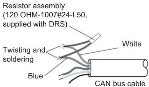
In addition to the CAN bus port found on the TZT9/14, all DRS radar sensors have one powered CAN bus port (terminal strip connector). You may directly connect various Furuno CAN bus sensors to the DRS radar sensor without having to run a separate CAN bus cable to the mast. The total number of sensors that can be connected to the CAN bus DRS port without external power connection depends on power consumption. The DRS can supply up to 1 amp (20LEN) to the DRS CAN bus network. Note that the CAN bus network connected to the DRS is its own independent CAN bus backbone and needs to be terminated at both ends by a terminating resistor. A 120 Ohm resistor is standard supply with the DRS to terminate the CAN bus. For example, if you install a SC-30/WS-200 with the DRS CAN bus port, you must have two terminators on the backbone. One can be at the sensor and the other located inside the DRS as shown in the inset at right.
text_image
Resistor assembly (120 OHM-1007#24-L50, supplied with DRS) Twisting and soldering White Blue CAN bus cable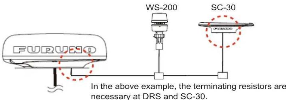
text_image
FURUNO WS-200 SC-30 In the above example, the terminating resistors are necessary at DRS and SC-30.Refer to the DRS Installation Manual for more information about connection.
NMEA0183 equipment
To connect an NMEA0183 equipment to TZT9/14, use the CAN bus network via the optional NMEA data converter IF-NMEA2K2 (or IF-NMEA2K1). This NMEA connection can accept a baud rate of 4800 or 38400.
Heading input to TZT9/14 allows functions such as Radar Overlay and course stabilization (North up, Course up, etc.) in the radar operating modes. The NMEA0183 heading refresh rate needs to be 100 ms in order for any radar function to work properly. NMEA0183 heading can be accepted on any CAN bus port at a baud rate up to 38400 bps. In other words, data sent (IF-NMEA) and received (TZT9/14) must use the same baud rate for each individual data port.
Note: Heading data from a CAN bus source/sensor is always at the correct refresh speed for the DRS ARPA function.
2.1.4 VIDEO, DVI-D, AUDIO or USB ports
How to connect VIDEO, DVI-D, AUDIO or USB ports
The above-mentioned ports are behind the connector cover on the rear panel. Access the ports and connect cables as shown in the procedure below.
Note: The display unit must be mounted in a console or indoors to do this connection because of reduced waterproofing.
- For TZT9, unfasten two binding screws to remove the fan cover.
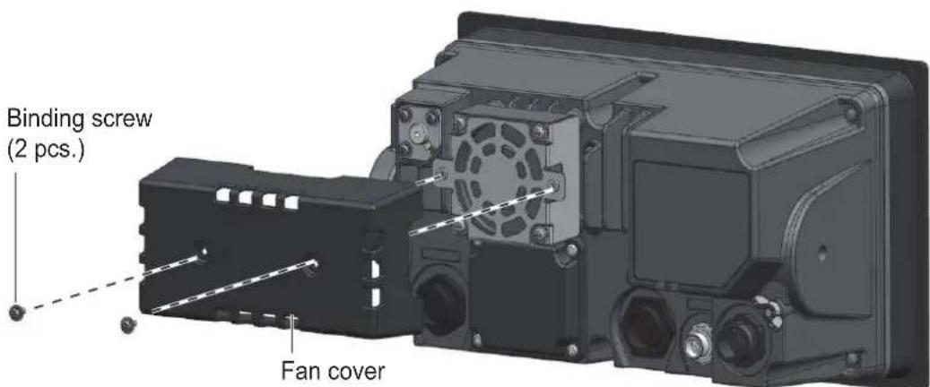
text_image
Binding screw (2 pcs.) Fan cover- Unfasten four binding screws to remove the connector cover at the rear of the equipment.
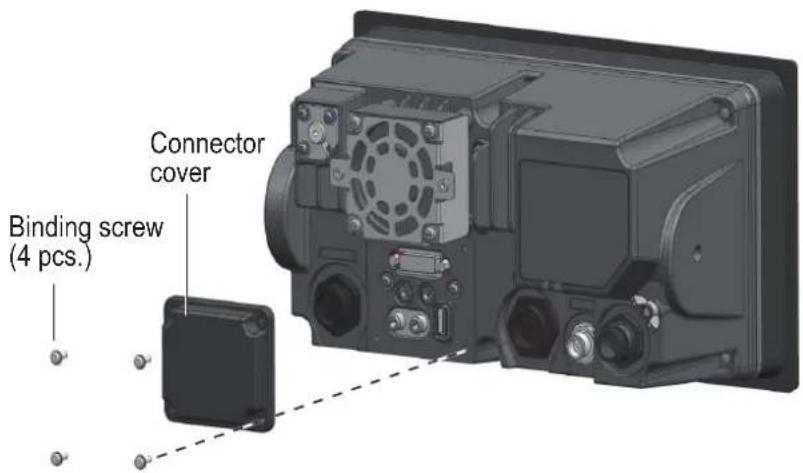
text_image
Connector cover Binding screw (4 pcs.)2. WIRING
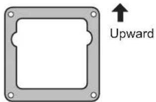
- Pass DVI-D, VIDEO, AUDIO and/or USB cables through the fixing metal (supplied).
Orient the fixing metal as shown below.
text_image
Upward-
Attach each connector to the appropriate location at rear of the equipment
-
Pass cables through the slit on the boot cover.
-
Pass cables through appropriate holes in the rubber stopper. The largest hole is for the DVI-D cable.
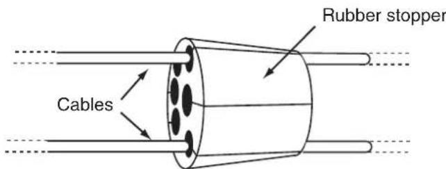
text_image
Rubber stopper Cables- Use four binding screws (M3x10, supplied) to fasten the fixing metal and boot cover to the equipment.
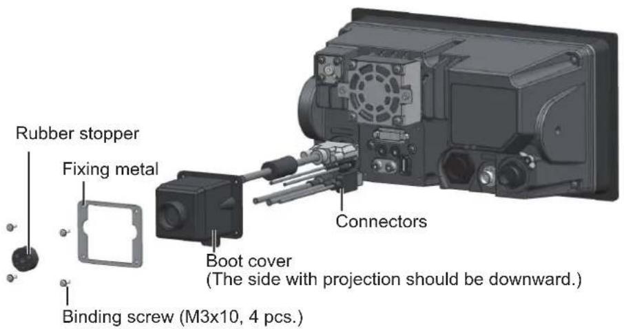
text_image
Rubber stopper Fixing metal Binding screw (M3x10, 4 pcs.) Connectors Boot cover (The side with projection should be downward.)- Slide the rubber stopper into the hole of the boot cover, use two cable ties to fasten the stopper to the boot cover.
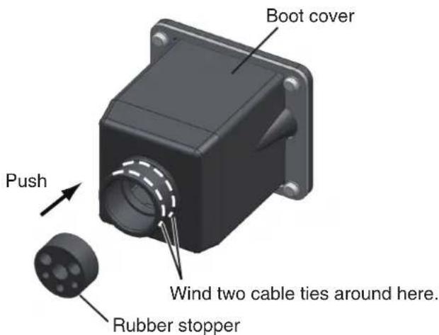
text_image
Boot cover Push Wind two cable ties around here. Rubber stopper- For TZT9, fasten two binding screws to re-attach the fan cover.
Video input
TZT9/14 can use regular analog video inputs (PAL or NTSC) that connect to the TZT9/14 directly or use IP cameras that connect directly to the network HUB. IP cameras can be seen by all TZT9/14 connected to the NavNet TZtouch network, unlike analog video that can be viewed only on the equipment where the source is connected. Additionally some IP cameras can be controlled from TZT9/14.
Analog video
The TZT9/14 units have two analog video inputs (PAL/NTSC) on 2 mm RCA (cinch) type connectors located on the rear of the equipment. For this connection, the following cable is necessary (local supply).
- 3C2V (Japan Industrial Standard (JIS), or the equivalent) coaxial cable (impedance: 75 )
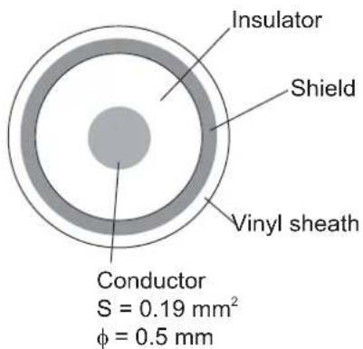
text_image
Insulator Shield Vinyl sheath Conductor S = 0.19 mm² φ = 0.5 mmIP camera
IP cameras are network devices that connect directly to a HUB. Up to four IP cameras can be connected to one NavNet TZtouch network. At this time, only AXIS IP cameras that support MPEG4 video are functional in the network. For more details, see the operator's manual for AXIS models.
DVI-D (external monitor)
A DVI monitor can be connected to the TZT9/14 to repeat the screen at a remote location. The plug is DVI-D format and only a DVI monitor with VESA DDC (Display Data Channel) can be connected. The TZT9/14 uses the monitor information (EDID) given via DDC to output the video data with the appropriate resolution. (The TZT14 has an 1280x800 (WXGA) DVI-D output and the TZT9 has an 800x480 (WVGA) DVI-D output.) Furuno offers two lengths of DVI cables, 5 m and 10 m.
Note: Use an external monitor that has the same aspect ratio as your equipment (TZT9: 5:3, TZT14: 16:10) to show the picture with proper size.
USB port
The TZT9/14 has one USB Ver. 2.0 port. This USB port can be used to connect a generic USB Touch Screen (compatible with Windows ^® 7 HID generic driver).
Audio
Outputs the audio line from the left-hand connector (Audio In is reserved for future development).
2.2 CAN bus/NMEA0183 Data Conversion and CAN bus Bridging
2.2.1 CAN bus networks/backbone
All DRS radar sensors have one CAN bus port (Terminal Block connector). You can directly Furuno CAN bus sensors to the DRS radar without having to run another CAN bus cable up the mast. In this case, each separate CAN bus network (the DRS CAN bus and the ship CAN bus) will be “Bridged” together via the Ether Network. Note that the TZT9/14 and DRS CAN bus ports must not be connected together.
Connection of multiple TZTs, no DRS radar sensor
Connect multiple TZTs with Ethernet and CAN bus cables.
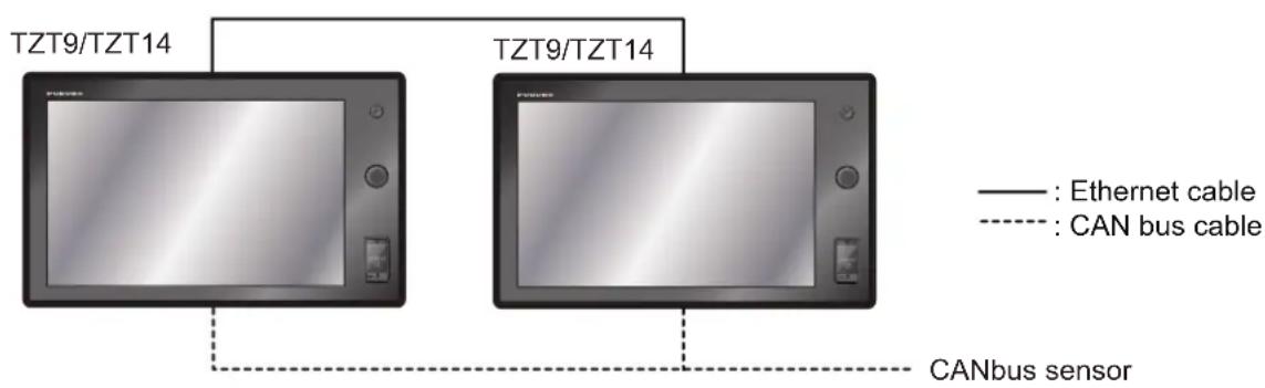
flowchart
graph TD
    A["TZT9/TZT14"] --> B["CANbus sensor"]
    C["TZT9/TZT14"] --> D["CANbus sensor"]
    style A fill:#f9f,stroke:#333
    style C fill:#f9f,stroke:#333
    style B stroke-dasharray: 5 5
    style D stroke-dasharray: 5 5
    note right of A
        Ethernet cable : Solid line
        CAN bus cable : Dashed line
    end
Connection of TZT and DRS radar sensor
Connect TZT to DRS radar sensor with Ethernet cable.
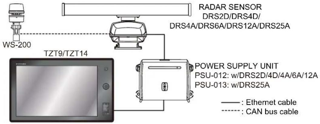
flowchart
graph TD
    A["WS-200"] --> B["TZT9/TZT14"]
    B --> C["RADAR SENSOR\nDRS2D/DRS4D/\nDRS4A/DRS6A/DRS12A/DRS25A"]
    C --> D["POWER SUPPLY UNIT\nPSU-012: w/DRS2D/4D/4A/6A/12A\nPSU-013: w/DRS25A"]
    D --> E["Power Supply Unit\nPSU-012: w/DRS2D/4D/4A/6A/12A\nPSU-013: w/DRS25A"]
    style A fill:#f9f,stroke:#333
    style B fill:#ccf,stroke:#333
    style C fill:#cfc,stroke:#333
    style D fill:#fcc,stroke:#333
    style E fill:#ffc,stroke:#333
2.2.2 CAN bus (NMEA2000) input/output
Input PGN
| No. | PGN Description | |
| 01. | 059392 ISO Acknowledgement | |
| 02. | 059904 ISO Request | |
| 04. | 060928 ISO Address Claim | |
| 06. | NMEA-Request Group Function | |
| 07. | NMEA Command | Group Function |
| 08. | NMEA-Acknowledge | Group Function |
| 11. | 126992 System Time | |
| 12. | 126996 Product Information | |
| 13. | 127237 Heading/Track Control | |
| 14. | 127245 Rudder | |
| 15. | 127250 Vessel Heading | |
| 16. | 127251 Rate of Turn | |
| 17. | 127257 Attitude | |
| 18. | 127258 Magnetic Variation | |
| 19. | 127488 Engine Parameters, Rapid Update | |
| 20. | 127489 Engine Parameters, Dynamic | |
| 21. | 127505 Fluid Level | |
| 22. | 128259 Speed | |
| 23. | 128267 Water Depth | |
| 24. | 129025 Position, Rapid Update | |
| 25. | 129026 COG & SOG, Rapid Update | |
| 26. | 129029 GNSS Position Data | |
| 27. | 129033 Time & Date | |
| 28. | 129038 AIS Class A Position Report | |
| 29. | 129039 AIS Class B Position Report | |
| 30. | 129040 AIS Class B Extended Position Report | |
| 31. | 129041 AIS Aids to Navigation (AtoN) Report | |
| 32. | 129291 Set & Drift, Rapid Update | |
| 33. | 129538 GNSS Control Status | |
| 34. | 129540 GNSS Sats in View | |
| No. | PGN | Description |
| 35. | 129793 AIS UTC and Date Report | |
| 36. | 129794 AIS Class A Static and Voyage Related Data | |
| 37. | 129798 AIS SAR Aircraft Position Report | |
| 38. | 129808 DSC Call Information | |
| 39. | 129809 AIS Class B “CS” Static Data Report, Part A | |
| 40. | 129810 AIS Class B “CS” Static Data Report, Part B | |
| 41. | 130306 Wind Data | |
| 42. | 130310 Environmental Parameters | |
| 43. | 130311 Environmental Parameters | |
| 44. | 130312 Temperature | |
| 45. | 130313 Humidity | |
| 46. | 130314 Actual Pressure | |
| 47. | 130577 Direction Data | |
| 48. | 130578 Vessel Speed Component | |
Output PGN
The CAN bus output PGN setting (found under the [Initial Setup] menu) is global to the network. Note that only one TZT9/14 will output CAN bus data on the network at a time: the TZT9/14 which is powered ON first. If that display is turned OFF, another will take its place to output the data.
| No. | PGN Description | Remark Output cycle (msec) | |
| 01. | 059392 ISO | Acknowledgement For Certification Level A/BRefusing output requirement | |
| 02. | 059904 ISO | Request For Certification Level A/BRquiring output | |
| 04. | 060928 ISO | Address Claim For Certification Level A/BAddress autonomyReceiving output requirement | |
| 05. | NMEA-Request group function | For Certification Level A/+αAddress autonomyReceiving output requirement | |
| 06. | NMEA-Comm 126208 | and group function | For Certification Level A/+αChanging the setting of other equipment |
| 07. | NMEA-Acknow | wledge group function | For Certification Level A/+αSending the confirmation for NMEA-Request group function and NMEA-Command group function |
| 08. | 126464 | PGN List-Transmit PGN's group function | For Certification Level A/+αReceiving output requirement |
| 09. | PGN List-Received | PGN's group function | For Certification Level A/+αReceiving output requirement |
| 12. | 126992 System Time 1000 | ||
| 13. | 126996 Product Information For Certification Level A/BRceiving output requirement | ||
| 14. | 127250 Vessel Heading | 100 | |
| 15. | 127251 Rate of Turn | 100 | |
| 16. | 127257 Attitude | 1000 | |
| 17. | 127258 Magnetic Variation | 1000 | |
| 18. | 128259 Speed | 1000 | |
| 19. | 128267 Water Depth | 1000 | |
| 21. | 129025 Position, Rapid Update | 100 | |
| No. | PGN | Description | Remarks | Output cycle (msec) |
| 22. | 129026 COG | & SOG, Rapid Update | 250 | |
| 23. | 129029 GNSS | S Position Data 1000 | ||
| 24. | 129033 Time | & Date 1000 | ||
| 25. | 129283 Cross | Track Error 1000 | ||
| 26. | 129284 Navigation Data 1000 | |||
| 27. | 129285 Navigation-Route/WP Information | • Outputs when waypoint is set/changed (own ship's position is required)• Outputs when receiving ISO request | ||
| 28. | 130306 Wind | Data 100 | ||
| 29. | 130310 Environmental Parameters | 500 | ||
| 31. | 130312 Temperature 2000 | |||
| 32. | 130313 Humidity Outputs when receiving the ISO request | |||
| 33. | 130314 Actual Pressure 2000 | |||
2.3 Example NavNet TZtouch System Configurations
Basic plotter/fish finder installation
The Furuno GP-320B is connected to the CAN bus backbone cable, using the optional NMEA data converter IF-NMEA2K2 (or IF-NMEA2K1). The DFF series network sounder is directly connected to the LAN port of the TZT using the standard supply cable (3 m).
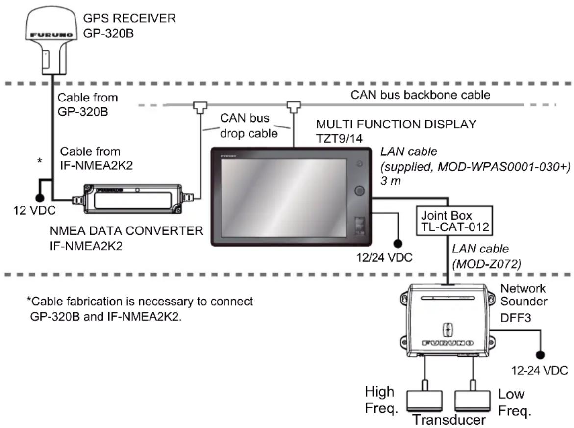
flowchart
graph TD
    A["GPS RECEIVER GP-320B"] -->|Cable from GP-320B| B["NMEA DATA CONVERTER IF-NMEA2K2"]
    B -->|CAN bus drop cable| C["MULTI FUNCTION DISPLAY TZT9/14"]
    C --> D["Joint Box TL-CAT-012"]
    D -->|LAN cable (MOD-Z072)| E["Network Sounder DFF3"]
    E --> F["Transducer"]
    E --> G["Low Freq."]
    H["*Cable fabrication is necessary to connect GP-320B and IF-NMEA2K2."] --> B
    I["12 VDC"] --> B
    J["12/24 VDC"] --> D
    K["CAN bus backbone cable"] --> C
    L["12-24 VDC"] --> E
2. WIRING
Basic plotter/radar/fish finder installation
This is a single station plotter/radar/fish finder installation. Connection of multiple sensors, such as DFF3 and DRS series, requires the optional Ethernet Hub HUB-101. Also, the power supply unit PSU-012, PSU-013 or PSU-017 is required for the connection with DRS.
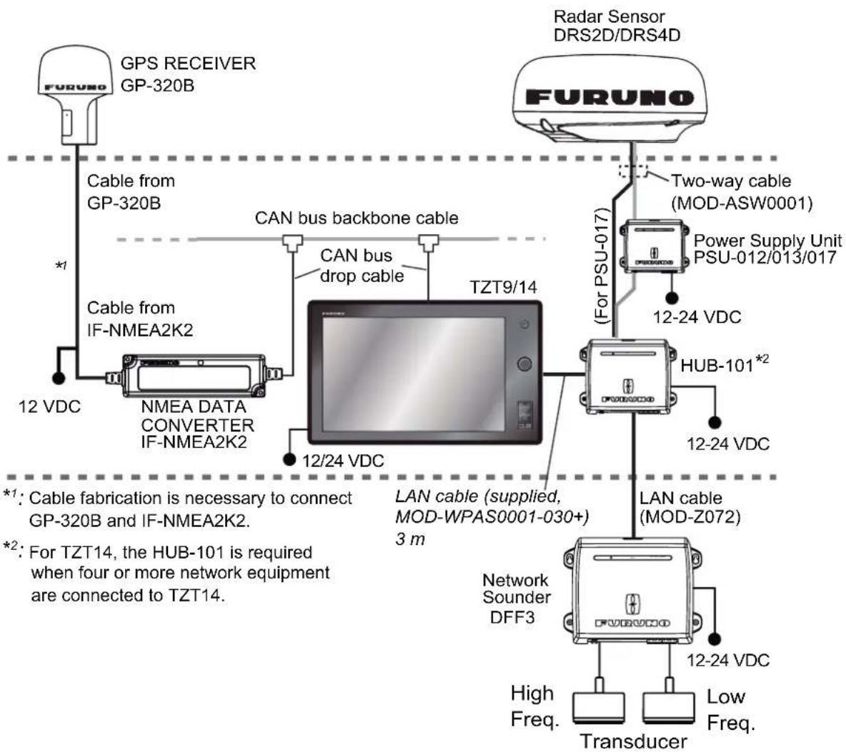
flowchart
graph TD
    A["GPS RECEIVER GP-320B"] -->|Cable from GP-320B| B["NMEA DATA CONVERTER IF-NMEA2K2"]
    A -->|Cable from IF-NMEA2K2| B
    B --> C["TZT9/14"]
    C --> D["Radar Sensor DRS2D/DRS4D"]
    D --> E["Two-way cable (MOD-ASW0001)"]
    D --> F["Power Supply Unit PSU-012/013/017"]
    D --> G["HUB-101*2"]
    G --> H["LAN cable (MOD-Z072)"]
    H --> I["Network Sounder DFF3"]
    I --> J["Transducer"]
    I --> K["High Freq."]
    I --> L["Low Freq."]
    style A fill:#f9f,stroke:#333
    style B fill:#ccf,stroke:#333
    style C fill:#cff,stroke:#333
    style D fill:#ffc,stroke:#333
    style E fill:#cfc,stroke:#333
    style F fill:#fcc,stroke:#333
    style G fill:#fcf,stroke:#333
    style H fill:#cff,stroke:#333
    style I fill:#ffc,stroke:#333
    style J fill:#cfc,stroke:#333
    style K fill:#fcc,stroke:#333
    style L fill:#cfc,stroke:#333
3. SETTING UP THE EQUIPMENT
This chapter shows you how to set up your system according to the equipment you have connected. You can do almost all operations on this equipment by just touching the display, following the instructions below.
Touch control description
The touch control depends on the screen type. The basic operations to use at the installation setting are in the following table.
Operation by a finger
| Operating by a finger Function | ||
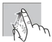
| Tap • Select a menu item. | 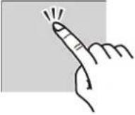 | • Select an object.• Display the pop-up menu. |
| Drag • Scroll the menu. | 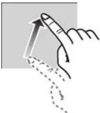 | |
Operation by two fingers
| Operation by two fingers Function | |||
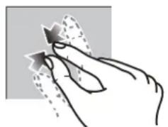
| Pinch Change the radar range | |||
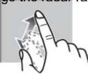 Zoom in Zoom in | 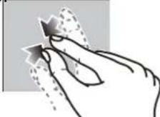 Zoom out Zoom out | ||
Note: When both RotokeyTM and touch control are available for the same function, this manual states the operation by touch control.
3. SETTING UP THE EQUIPMENT
About menu operations
The following procedure shows how to use the menu system.
- Press the key to turn the power on.
- After the display selection window appears (approx. 90 seconds), press the Home key to show the menu icon bar.
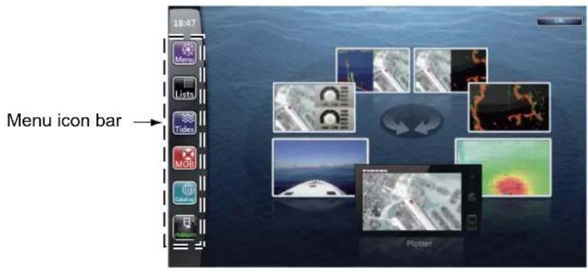
text_image
18:47 Menu icon bar → Plotter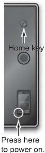
text_image
Home key Press here to power on.- Select (tap) the [Menu] icon () to open the main menu.
text_image
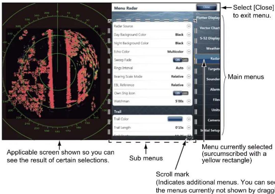
Menu Radar Close Select [Close] to exit menu. Plotter Display Radar Source Day Background Color Black Night Background Color Black Echo Color Multicolor Sweep Fade ON OFF Rings Interval Auto Bearing Scale Mode Relative EBL Reference Relative Own Ship Icon ON OFF Watchman 5'00s Trail Trail Color Trail Length 0'15s Main menus Applicable screen shown so you can see the result of certain selections. Sub menus Menu currently selected (surcumscribed with a yellow rectangle) Scroll mark (Indicates additional menus. You can see the menus currently not shown by draggi- Drag the main menus on the right-hand side of the screen. The current selection is circumscribed with a yellow rectangle. The sub menus for the selected menu appear.
You can also select a menu by rotating the RotoKey ^TM .
- Select the menu item to set from the sub menu.
There are four types of icons to indicate how to set a menu item, and each has the unique function as shown on the next page.
| Icon Description | |
 | This icon means that menu item has some options. Touch it to show the option window (pull-down list). |
 | Touch the menu item with this icon to display the soft-ware keyboard, to enter alphanumeric data. For de-tails, see “How to use the software keyboard” shown below. |
 | Shows a sub menu.Switches a functions ON and OFF.Selects a color. |
 | Drag the circle icon to adjust the setting value. |
- Select [Close] at the top right-hand side of the screen to exit the menu.
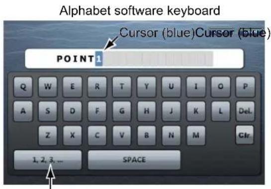
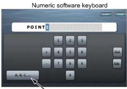
(How to use the software keyboard)
text_image
Alphabet software keyboard Cursor (blue) Cursor (blue) POINT1 Q W E R T Y U I O P A S D F G H J K L Del. Z X C V B N M Glr. 1, 2, 3, ... SPACESelect this to switch to the numeric software keyboard.
text_image
Numeric software keyboard POINT 1 1 2 3 + 4 5 6 - 7 8 9 Del. Ctr. A, B, C, ...Select this to switch to the alphabet software keyboard.
3.1 How to Set Time Zone, Language and Units
Before setting up your equipment, select the time zone, language and units to use on your equipment as shown below.
- Press the Home key, then select [Menu] icon (Manu) from the menu icon bar.
- Select [General] on the main menu to show the [Menu General] sub menus.
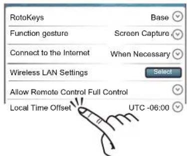
- Select [[Local Time Offset]] to show the option window.
text_image
RotoKeys Function gesture Screen Capture Connect to the Internet When Necessary Wireless LAN Settings Select Allow Remote Control Full Control Local Time Offset UTC -06:003. SETTING UP THE EQUIPMENT
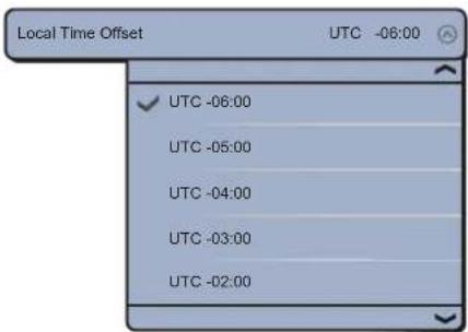
- Select time difference between local time and UTC time to use local time from the pull-down list.
text_image
Local Time Offset UTC -08:00 ✓ UTC -06:00 UTC -05:00 UTC -04:00 UTC -03:00 UTC -02:00- Select [Language] to show its option window.
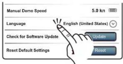
text_image
Manual Demo Speed 5.0 kn Language English (United States) Check for Software Update Update Reset Default Settings Reset-
Select the language to use.
-
Drag the main menu to select [Units], and set the units to show on the display.
[Menu Units] sub menus
| Menu item Options | ||
| [Bearing Display] [True], [Magnetic] | ||
| [True Wind Calculation Reference] | [Ground], [Surface] | |
| [Position Format] [DDD°MM.mmmm'], [DDD°MM.mmm'], [DDD°MM.mm'], [DDD°MM'SS.ss"], [DDD.dddddd°], [Loran C], [MGRS] | ||
| [Loran C Station & GRI] [GRI] | I Select GRI code. | |
| [Master] - | ||
| [First (Second) Slave] X: Upolu Point, Y: Kure Island | ||
| [Correction First (Second) Slave] | Enter a position offset to refine Loran C position. | |
| [Range (Long)] [Nautical Mile], [Kilometer], [Mile] | ||
| [Range (Short)] [Foot], [Meter], [Yard] | ||
| [Short/Long Change Over] | Set the distance at which to change between short and long range. Set the long range here. | |
| [Depth] [Foot], [Meter], [Fathom], [Passi Braza] | ||
| [Height/Length] [Foot], [Meter] | ||
| [Temperature] [Fahrenheit Degree], [Celsius Degree] | ||
| [Boat Speed] | [Knot], [Kilometer per Hour], [Mile per Hour], [Meter per Second] | |
| [Wind Speed] | [Knot], [Kilometer per Hour], [Mile per Hour], [Meter per Second] | |
| [Atmospheric Pressure] | [HectoPascal], [Millibar], [Millimeter of Mercury], [Inch of Mercury] | |
| [Oil Pressure] | [KiloPascal], [Bar], [Pound per Square Inch] | |
| [Volume] | [Gallon] (Gallon & Gallon/hour), [Liter] (Liter & Liter/hour) | |
| [Reset Default Settings] Restore default unit settings. | ||
3.2 Menu Initial Setup
This section shows you how to set your system according to the sensors you have connected.
Drag the main menu, then select the [Initial Setup] to show the [Menu Initial Setup] sub menus.
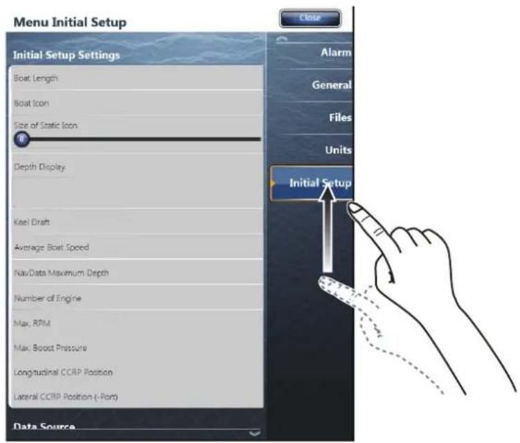
text_image
Menu Initial Setup Initial Setup Settings Boat Length Boat Icon Size of Static Icon Depth Display Keel Draft Average Boat Speed NavData Maximum Depth Number of Engine Max. RPM Max. Boost Pressure Longitudinal CCRP Position Lateral CCRP Position (-Port) Data Source Close Alarm General Files Units Initial SetupMenu Initial Setup
| Menu item Description Options (setting range) | ||
| [Boat Length] Set the length of your boat. 5.0 to 9,999 ft | ||
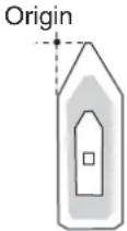
| [Longitudinal GPS Position] | Enter the GPS antenna positioning bow-stern (Longitudinal) and port-star-board (Lateral) position from the origin. | |
| [Lateral GPS Position (-Port)] | 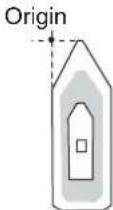 | |
| [Boat Icon] Select the icon that best matches your boat. | [Sport Fishing], [Cruiser], [Sail-boat], [Commercial] | |
| [Size of Static Icon] Set the size of static (such as own ship) icons. | 50 to 150 | |
| [Depth Display] Select the start point for depth measurement. | [Under Keel], [Under Sea Lev-el] | |
3. SETTING UP THE EQUIPMENT
| Menu item | Description | Options (setting range) |
| [Transducer Draft Source] | Select the draft source to use on the display, among the following:Automatic: Use the offset value in the DPT sentence. If the DPT sentence does not have an offset value, the value entered at Transducer Draft (page 3-11) is used.Hardware: Use the offset value in the DPT sentence from an echosounder.Manual: Use the value entered at Transducer Draft (page 3-11). | [Automatic], [Hardware], [Manual] |
| [Keel Draft] Set the keel | draft. 0.0 to 99 ft | |
| [Average Boat Speed] | Select your boat type to use for average speed calculation. | [Sailing], [Commercial], [Powerboat] |
| [Nav Data Maximum Depth] | Select the maximum depth for navigation data. | [Very Shallow] (under 10 m), [Shallow] (10 to 20 m), [Deep] (20 to 200 m), [Very Deep] (200 to 2000 m) |
Menu Initial Setup (Engine)
| Menu Item Description | Option Options (setting range) | |
| [Number of Engine] Select the maximum rpm of your engine to show on the RPM display. | [1], [2], [3], [4] | |
| [Max. RPM] Set the starting value for the red zone area of the tachometer. | 1000 to 20,000 rpm | |
| [Red Zone RPM] Set the starting value for the red zone area of the oil pressure meter. | 0 to 20,000 rpm | |
| [Red Zone Oil Pressure] Set the starting value for the red zone area of the oil pressure meter. | 0 to 999 kPa | |
| [Red Zone Temperature] Set the starting value for the red zone area of the engine temperature indicator. | 0°F to 999°F | |
| [NickName Engine 1 to 4] | Change the nickname for engine 1 to 4. | |
Menu Initial Setup (Fuel)
| Menu Item Description | Option Options (setting range) | |
| [Number of Tank] | Select the number of fuel tanks on your boat. | [1], [2], [3], [4] |
| [NickName Tank 1 to 4] | Change the nickname for fuel tank 1 to 4. | |
Manu Initial Setup (Use Fuel Tank for calculations)
| Menu Item Description | Options (setting range) | |
| [Tank 1 to 4] | Select the tanks to calculate the fuel consumption. | [ON], [OFF] |
Menu Initial Setup (Data Acquisition)
| Menu Item | Description | Options (setting range) |
| [GP330B WAAS Mode] | Select [ON] to use the WAAS mode for the corresponding GPS antenna. | [ON], [OFF] |
| [WS200 WAAS Mode] | ||
| [Data Source] Select the source for each data to input to the system. If two or more sources are connected for a data, select one using the pull-down dialog box. The Furuno products are shown at the upper part of the list. | ||
| [Sensor List] Show the information for sensors connected to your equipment. Also, you can set “Nickname” for them here. | ||
| [PGN Output] Select [ON] for the PGNs (Parameter Group Number, CAN bus (NMEA2000) message) to output from the CAN bus port. | ||
| [Sky View] Show the condition of GPS and GEO (WAAS) satellites. Number, bearing and elevation angle of all GPS and GEO satellites (if applicable) in view of your receiver appear. | ||
Menu Initial Setup (SC-30 Setup)
| Menu item Description Options (setting range) | ||
| [WAAS Mode] Select [ON] to use the WAAS mode. | ||
| [Heading Offset] Enter the offset value for heading. -180° to +180° | ||
| [Pitch Offset] Enter the offset value for pitching. -180° to +180° | ||
| [Roll Offset] Enter the offset value for rolling. -180° to +180° | ||
Menu Initial Setup (Calibration)
| Menu item Description Options (setting range) | ||
| [Heading] | Offset heading data. | -180.0° to +180.0° |
| [Speed Through Water] | Calibrate speed data. Enter amount in percentage. | -50% to +50% |
| [Wind Speed] | Offset wind speed data. Enter amount in percentage. | -50% to 50% |
| [Wind Angle] | Offset wind angle data. | -180° to +180° |
| [Sea Surface Temperature] | Offset sea surface temperature data. | -10°C to +10 °C |
Menu Initial Setup (Data Damping)
| Menu item | Description | Options (setting range) |
| [COG & SOG] | Set data damping time. The lower the setting the faster the response to change. | 0 to 59 seconds |
| [Heading] | ||
| [Speed Through Water] | ||
| [Wind Speed & Angle] | ||
| [Rate of Turn] |
Menu Initial Setup (Browser Installation)
| Menu item | Description | Option (setting range) |
| [FAX30 Browser] | Show the Facsimile Receiver FAX-30 display. | |
| [FA30 Browser] Show the AIS Receiver FA-30 display. | ||
| [FA50 Browser] Show the AIS Receiver FA-50 display. | ||
Note: The [External Touch Screen Mode] allows you to facilitate the operation of the TZT9/TZT14 when an external dual touch screen is connected to the MFD via the USB and DVI-D ports. When the [External Touch Screen Mode] is set to [ON], the contextual Rotokeys appear near the cursor and the dual gesture is set automatically to display the "Home" screen.
3. SETTING UP THE EQUIPMENT
3.3 How to Set up the Radar
If you have a radar sensor, set the sensor's characteristics on the [Radar] menu. Open the [Menu Radar] sub menus. Drag the main menu to select [Radar].
- Select [Radar Source] on the [Menu Radar] sub menus, then select the radar type connected.
Note: If a DRS sensor is connected but does not appear in the [Radar Source] list, close the list and open it again. The name of the DRS sensor should appear with a check mark, as in the example below.
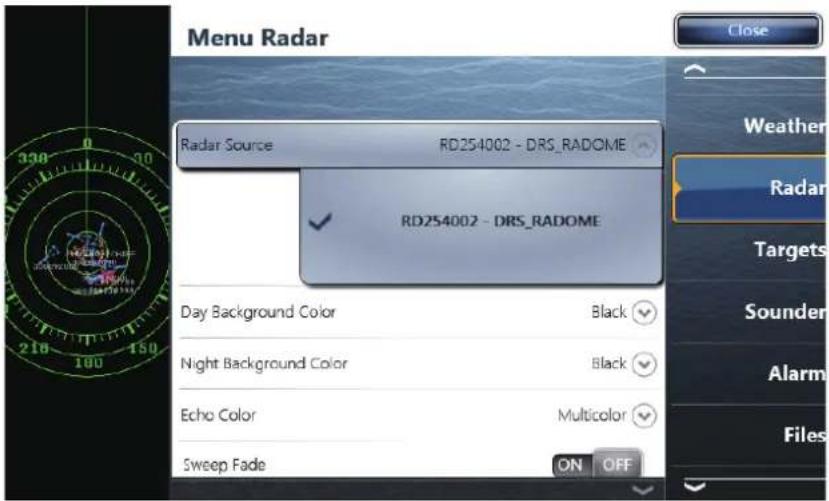
text_image
Menu Radar Radar Source RD254002 - DRS_RADOME RD254002 - DRS_RADOME Day Background Color Black Night Background Color Black Echo Color Multicolor Sweep Fade ON OFF- Drag the [Menu Radar] sub menus to find the menu item [Radar Initial Setup].

text_image
Title Menu Radar Radar Initial Setup Antenna Rotation Auto Antenna Heading Align +0.0 ° Main Bang Suppression Enable Sector Blanking ON OFF Start Angle P End Angle P Antenna Height 3m Antenna Longitudinal Position Antenna Lateral Position (-Port) Auto Tuning Tuning Source Rangel Manual Tuning Close Plotter Display Vector Chart S-52 Display Weather Radar Targets Sounder Alarm FilesMenu Radar (Radar Initial Setup)
| Menu item Description | Options (setting range) | |
| [Antenna Rotation] Select the speed of antenna rotation. | [Auto], [24 RPM], [48 RPM] | |
| [Antenna Heading Align] See the topic of “How to align the antenna heading” shown below. | -180° to +180° | |
| [Main Bang Suppression] If main bang appears at the screen center, slide the circle icon so that the main bang disappears, while watching the radar echo at the left-hand side of the display. | 0 to 100 | |
| [Antenna Height] Select the height of the antenna above the waterline. | [5m], [7.5m], [10m], [15m], [20m], [25m], [30m], [35m], [40m], [45m], [50m] | |
| [Antenna Longitudinal Position] | Enter the antenna positioning bow-stern (Longitudinal) and port-starboard (lateral) position from the origin. | |
| [Antenna Lateral Position (-Port)] | ||
 | ||
| Others See Operator' Manual for TZT9/14. | ||
How to align the antenna heading
You have mounted the antenna unit facing straight ahead in the direction of the bow. Therefore, a small but conspicuous target dead ahead visually should appear on the heading line (zero degrees).
In practice, you will probably observe some small bearing error on the display because of the difficulty in achieving accurate initial positioning of the antenna unit. The following adjustment will compensate for the error.
1) Set your radar with 0.125 and 0.25 nm range and the head up mode.
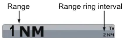
You can select a range by a pinch action. The range and range ring interval appear at the bottom left of the screen.
Zoom in
natural_image
Hand holding a star-shaped object with a dotted pattern, no text or symbols visibleZoom out
text_image
Range Range ring interval 1 NM Tx 2 NMRange indications
Pinch action
2) Turn the vessel's bow toward a target.
3) Press the Home key, then select [Menu] icon, [Radar], and [Antenna Heading Align] in that order to show the numeric software keyboard.
4) Key in the offset value so that the target becomes at the very top of the screen (setting range: +/- 0° to 180°, +: clockwise direction, -: counterclockwise direction), then tap [Save].
5) Confirm that the target echo is displayed at correct bearing on the screen.
3.4 How to Set up the Sounder
If you have a sounder (FCV-1150, BBDS1 or DFF series), set up the sounder as shown in this section. Drag the main menu to select [Sounder]. You can confirm the actual sounder display on the left-hand side of the screen while setting up.
Drag the [Menu Sounder] sub menus to select [Sounder Initial Setup] on it.
| Menu item Description | Options (setting range) | |
| [Zero line Rejection] | When you turn the zero line (transmission line) rejection off, the line is not shown, which allows you to see fish echoes near the surface. The width of the line changes with the transducer used and installation characteristics. If the width of the line is 1.4 m or more, select [ON]. | [ON], [OFF] |
| [Zero line Range] When [ON] is selected at [Zero line Rejection], set the effective area. | 1.4 to 2.5 m | |
| [Transducer Draft] Set the distance between the transducer and the draft line to show the distance from the sea surface. | 0.0 to 99.9 ft | |
| [Salt Water] Select [ON] in you use this equipment in salt water. [ON], [OFF] | ||
| [Fish Finder Source] | Select the sounder used. [SOUNDER- | DFF1], [SOUNDER-DFF3], [SOUNDER-DFF1-UHD], [SOUNDER-BBDS1], [SOUNDER-FCV-1150] |
| [Transducer Setup] Select the method to setup the transducer, manually or by selecting the model number.Manual: Enter high/low frequencies and TX power.Model Number: Select the type of the transducer connected. | [Manual], [Model Number] | |
Motion sensor setting up
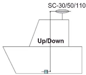
When you tap the [Transducer Setup], the [Motion Sensor] sub menus are shown beneath the [Transducer Setup] sub menus. If the satellite compass SC-30 or SC50/110 is connected, set the distance between the antenna unit (or sensor) of the satellite compass and transducer (high and low if connected) here.
- Motion Sensor Type: Select [SC30] or [SC50-SC110] depending on the sensor connected.
- Motion Sensor Antenna Position Bow/Stern HF (LF): Set the distance from the antenna unit to the transducer in the bow-stern direction. If the transducer is located on the fore side, set a positive value.
- Motion Sensor Antenna Position Up/Down HF (LF): Set the distance from the transducer to the antenna unit in the vertical direction.
- Motion Sensor Antenna Port/Starboard HF (LF): Set the distance from the antenna unit to the transducer in the port-starboard direction. If the transducer is located on the starboard side, set a positive value.
text_image
SC-30/50/110 Up/Down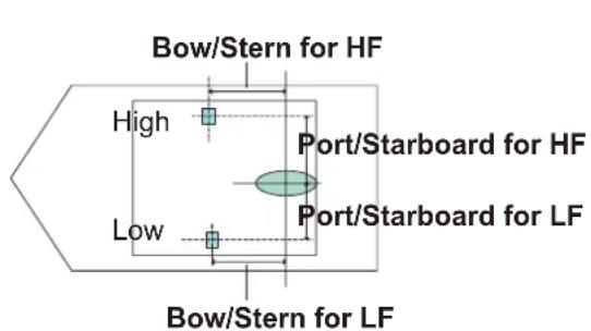
text_image
Bow/Stern for HF High Port/Starboard for HF Low Port/Starboard for LF Bow/Stern for LF3.5 Wireless LAN Setting
The TZT9/14 can be configured to create a wireless network (“Ad Hoc”) or to connect to an existing wireless network. Connecting to an existing wireless network is very useful if you already have an Access Point setup on your boat, especially if you have Internet available. Simply connect the TZT9/14 and your smartphone or tablet to the existing wireless network. Since the TZT9/14 and smartphone/tablet device will be on the same network, you will be able to share data (using the “NavNet Viewer” App) as well as access the internet (for Weather downloads). Please note that in this configuration, the “NavNet Remote” App performance is inferior due to a larger amount of data being exchanged between the iPad and the MFD (through the access point). The “NavNet Viewer” App performance will not be affected in this mode, as the bandwidth usage is very low. If you do not have an existing wireless access point on your boat or if you want to achieve the best performance with the “NavNet Remote” App, we recommended you establish a “point-to-point” connection. This can be accomplished by configuring the MFD to create a WiFi network (Ad Hoc network). In this mode, the MFD becomes an Access Point (you can setup the network name and password) to which the phone/tablet can connect directly.
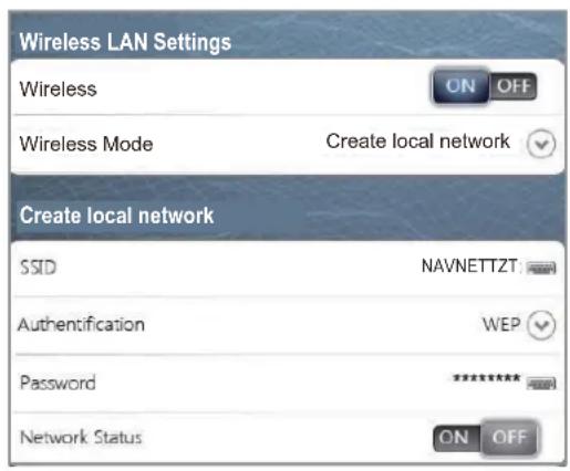
Create a wireless LAN network to use the application on your smartphone or tablet with the wireless LAN signal. Select [Wireless LAN Settings] on the [Menu General] sub menus.
text_image
Wireless LAN Settings Wireless ON OFF Wireless Mode Create local network Create local network SSID NAVNETTZT Authentication WEP Password ********** Network Status ON OFFWireless LAN Settings sub menus
How to create a new Wireless LAN network
- Select [ON] at [Wireless].
- Select [Create local network] at [Wireless Mode].
- Set items as shown below.
| Item Description Options | ||
| [SSID] Enter SSID ($Service Set Identifier) to use. | Maximum 32 characters | |
| [Authentication] Select the authentication. [Open], [WEP], [WPA2-PSK] | ||
| [Password] Enter the password for connection to the LAN. | Numbers of the character depends on the selection at [Authentica-tion]. | |
| [Network Status] Select [ON] to connect with your tablet/ smartphone over wireless LAN network. | [ON], [OFF] | |
3. SETTING UP THE EQUIPMENT
This page is intentionally left blank.
PACKING LIST TZT9
| NAME OUTLINE | Q' TYDESCRIPTION/CODE No. |
ユニット UNIT
| NAME OUTLINE | Q' TYDESCRIPTION/CODE No. |
ユニット UNIT
| NAME OUTLINE | Q' TYDESCRIPTION/CODE No. |
ユニット UNIT
| NAME OUTLINE | Q' TYDESCRIPTION/CODE No. |
ユニット UNIT
BULKHEAD THICKNESS (A): 5≤A≤25.
REMOUNT FIXTURE (\$) WHEN THE VALUE CROSSES OVER 15 mm.
NOTE
text_image
236±1 386±1 R13text_image
Electrical schematic diagram of a multi-function display system with component labels, wiring, and control signals in Japanese.The paper used in this manual is elemental chlorine free.
FURUNO ELECTRIC CO., LTD.
9-52 Ashihara-cho,
Nishinomiya, 662-8580. JAPAN
All rights reserved.
Printed in Japan
Pub. No. IME-44700-D
(REFU) TZT9/14
• FURUNO Authorized Distributor/Dealer
A : FEB. 2012
D : MAR. 27, 2013
* 0 0 0 1 7 6 0 1 8 1 3 *