
EM4001 - Uncategorized Eminent - Free user manual and instructions
Find the device manual for free EM4001 Eminent in PDF.


| Product Type | Multimedia Player / Network Device |
| Brand | Eminent |
| Model | EM4001 |
| Dimensions (W x D x H) | 12.0 x 8.0 x 2.5 cm |
| Weight | 200 g |
| Power Supply | USB 5V DC, 1A |
| Power Consumption | 5 W (max) |
| Supported Media Formats | MP3, WAV, FLAC, JPEG, MP4, AVI |
| Network Interfaces | Wi-Fi 802.11 b/g/n, Ethernet 10/100 |
| USB Ports | 1 x USB 2.0 (host) |
| Audio Output | 3.5 mm stereo jack, RCA stereo |
| Video Output | HDMI 1.4, composite video (RCA) |
| Key Functions | Media playback, file browsing, network streaming, photo viewer |
| Remote Control | Infrared remote included |
| Warranty | 1 year limited warranty |
| Cleaning | Wipe with a soft dry cloth. Do not use liquids or solvents. |
| Safety Precautions | Keep away from moisture. Do not disassemble. Use only supplied power adapter. |
| Spare Parts & Repairability | No user-serviceable parts. Contact Eminent support for repairs. |
| General Information | For full details, refer to the user manual at notice-facile.com |
Frequently Asked Questions - EM4001 Eminent
User questions about EM4001 Eminent
0 question about this device. Answer the ones you know or ask your own.
Ask a new question about this device
Download the instructions for your Uncategorized in PDF format for free! Find your manual EM4001 - Eminent and take your electronic device back in hand. On this page are published all the documents necessary for the use of your device. EM4001 by Eminent.
USER MANUAL EM4001 Eminent
10/100BASE-TX TO 100BASE-FX MEDIA CONVERTERS
EM4000
EM4001
Installation Guide
The information contained in this document is subject to change without prior notice. Copyright (C) All Rights Reserved.
TRADEMARKS
Ethernet is a registered trademark of Xerox Corp.
FCC NOTICE
This device complies with Class B Part 15 the FCC Rules. Operation is subject to the following two conditions: (1) This device may not cause harmful interference, and (2) this device must accept any interference received including the interference that may cause.
CE NOTICE
Marking by the symbol indicates compliance of this equipment to the EMC directive of the European Community. Such marking is indicative that this equipment meets or exceeds the following technical standards:
EMC Class B
EN 50081-1/1992 : EN55022, EN61000-3-2, EN61000-3-3
EN 50082-1/1998 : EN61000-4-2, EN61000-4-3, EN61000-4-4, EN61000-4-5, EN61000-4-6, EN61000-4-8, EN61000-4-11
Table of Contents
1. Introduction......4
1.1 Key Features .... 4
1.2 Specifications 5
1.3 Optical Specifications 8
1.4 Special Functions 9
2. Installation.... 11
2.1 Unpacking ....11
2.2 Mounting the Device ....11
2.3 Applying Power 12
2.4 Making TP Port Connection 12
2.5 Making FX Port Connection 13
2.6 LED Indicators 14
2.7 Smart Forwarding 15
1. Introduction
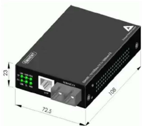
The 10/100BASE-TX to 100BASE-FX media converter series provides a media conversion allowing high-speed integration of fiber optic and twisted-pair segments. With 10BASE-T and 100BASE-TX support, the converters provide seamless translation between Ethernet and Fast Ethernet networks. A complete set of LEDs allows for quick status verification.
text_image
I/O port I/O port I/O base 23 72.5 1081.1 Key Features
The media converters also provide the following key features:
- Convert speed and media type
- Support full wire speed conversion
- Support 10Mbps and 100Mbps speed on TP connections
• Auto MDI/MDI-X detection function on the TP port
• Auto-negotiation function on the TP port - Link fault pass through function
- Transparent to 802.1Q VLAN tagged packets
• Far End Fault function on FX port - Low power consumption
- Support center chassis installation (up to 16 units n one chassis)
1.2 Specifications
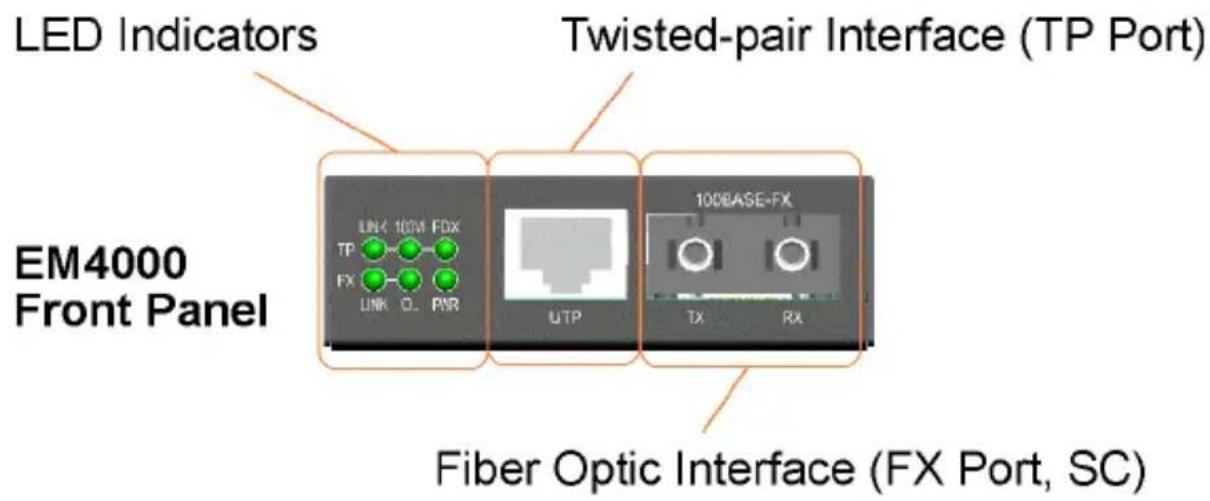
text_image
LED Indicators Twisted-pair Interface (TP Port) EM4000 Front Panel LINK 10CM FDX TP FX LINK O. PVR UTP 100BASE-FX TX RX Fiber Optic Interface (FX Port, SC)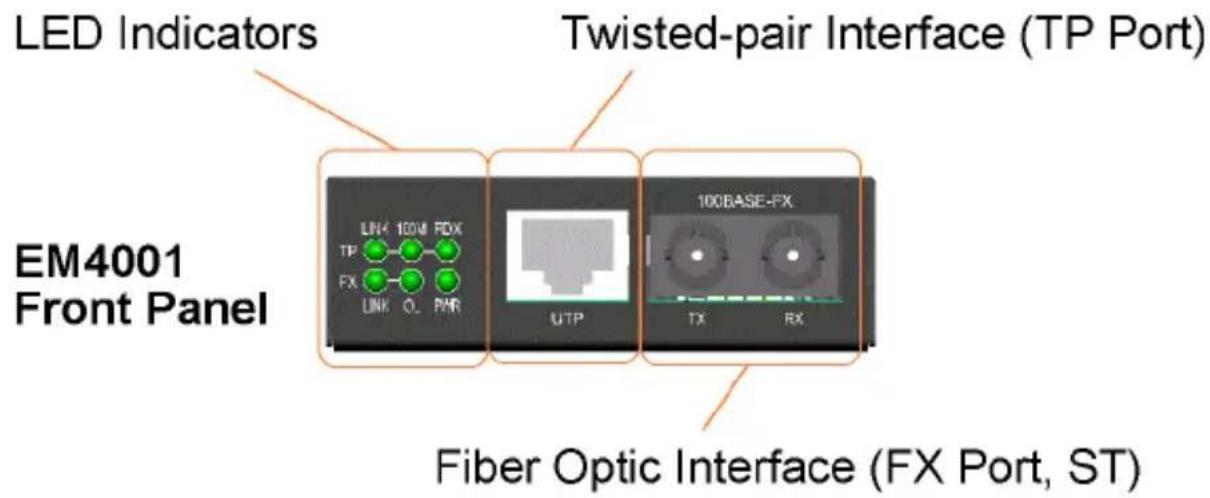
text_image
LED Indicators Twisted-pair Interface (TP Port) EM4001 Front Panel LINK 100M FDX TP FX LINK OL PWR UTP 100BASE-FX TX RX Fiber Optic Interface (FX Port, ST)
text_image
DC Power Input Rear Panel +7.5V/1.0A CENTER Center Connector with coverTwisted-Pair Interface (TP Port)
Connector Shielded RJ-45
Pin Assignments Auto MDI/MDI-X detection
Signal Compliance IEEE802.3 10BASE-T,802.3u 100BASE-TX
Data Speed 10Mbps or 100Mbps
Duplex Mode Half-duplex or Full-duplex
Configuration Auto-negotiation capable and optional
forced manual settings
Cable Types 10Mbps - Category 3, 4, or 5 UTP
100Mbps - Category 5 UTP
Supported Link Distance Up to 100 meters
Fiber Optic Interface (FX Port)
Signal Compliance IEEE 802.3u 100BASE-FX
Connector EM4000 - SC connector
EM4001 - ST connector
Data Speed 100Mbps
Duplex Mode Full-duplex and optional half duplex
Cable Types
Multimode (MMF) - 50/125, 62.5/125 mm
Single mode (SMF) - 9/125 mm
Supported Link Distance MMF up to 2km
SMF up to 100km
Single SMF WDM up to 40km
Eye Safety compliance IEC825 Class 1
LED Indicators
LED DISPLAY STATE INTERPRETATION
PWR Power status ON Power on
OFF Power off
TP LINK TP port link status ON Link up and no traffic
OFF Link fault
Blink Rx/Tx activities
TP 100M TP port speed status ON 100Mbps
OFF 10Mbps
TP FDX TP port duplex status ON Full duplex
OFF Half duplex
Blink Collisions on half duplex
FX LINK FX port link status ON Link up and no traffic
OFF Link fault
Blink Rx/Tx activities
FX OL FX port optical link ON Optical signal is detected
OFF No optical signal
DC Power Input
DC Input Jack D 6.3mm - —●— + D 2.0mm
Operating Input Voltages +4.75V \~ +12.6V
Power consumption 2W max. (0.27A @+7.5V)
Power Supply Options External AC-DC power adapters
Rated AC120V/60Hz DC7.5V 1A
Rated AC230V/50Hz DC7.5V 1A
Rated AC100V/50-60Hz DC7.5V 1A
Rated AC100V/50-60Hz DC5V 1A
Rated AC240V/50Hz DC7.5V 1A
Basic Information
Forwarding Throughput Full wire speed at 100M full duplex
10Mbps - 14,880 pps at 64-byte packets
100Mbps - 148,800pps at 64-byte packets
Packet Types Transparent and no modification for
- IEEE 802.3 standard packets
- IEEE 802.1Q VLAN tagged packets
Packet Length Up to 1522 bytes at 10 to 100 mode
No limit at 100 to 100 mode
Flow Control Back-pressure for half-duplex mode
802.3x pause-frame base for full duplex mode
Mechanical
Dimension H 23mm x W 72.5mm x D 108mm
Housing Enclosed metal with no fan
Mounting Desktop, Wall mount, Center chassis
Weight 210g
Environmental
Operating Temperature -5 ^ C \~ 40 ^ C
Storage Temperature -20 ^ C \~ 85 ^ C
Relative Humidity 5% \~ 90%
Certificate
FCC Part 15 Class B
CE/EMC EMI EN50081-1 Class B, EMS EN55024
CE/LVD EN 60950
1.3 Optical Specifications
The media converter series provides the following fiber options:
Duplex Fiber Series
| Model | Port | Fiber | Wavelength | Tx Power | Rx Sensitivity |
| EM4000 | SC | MMF | 1310nm | -19 ~ -14dBm | -33dBm |
| EM4001 | ST | MMF | 1310nm | -19 ~ -14dBm | -33dBm |
1.4 Special Functions
Auto MDI/MDI-X Function
This function allows the TP port to auto-detect the twisted-pair signals and adapts itself to form a valid MDI to MDI-X connection with the remote connected device automatically.
Auto-negotiation Function
The TP port is featured with auto-negotiation function and full capability. It performs a negotiation process for the speed and duplex configuration with the connected device automatically when each time a link is being established.
Far End Fault Function
The FX port is facilitated with this function, which conforms to IEEE 802.3u 100BASE-FX specifications. When the FX port detects a link failure on its receiving circuitry, it will send out an FEFI (Far End Fault Indication) signal to the remote connected device to indicate a remote fault is detected. It also is capable to receive FEFI signal sent from the remote link partner. Upon receiving an FEFI signal, it indicates a link failure occurred on the transmitting path. This function allows the converter to report a fiber link fault even when a link failure occurred on transmitting fiber cable.
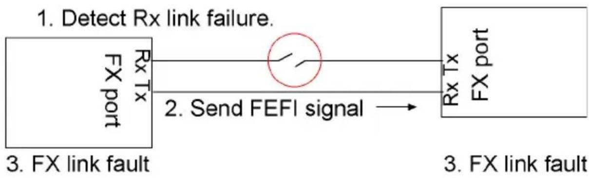
flowchart
graph LR
    A["1. Detect Rx link failure."] --> B["2. Send FEFI signal"]
    B --> C["3. FX link fault"]
    C --> D["3. FX link fault"]
Link Fault Pass Through Function
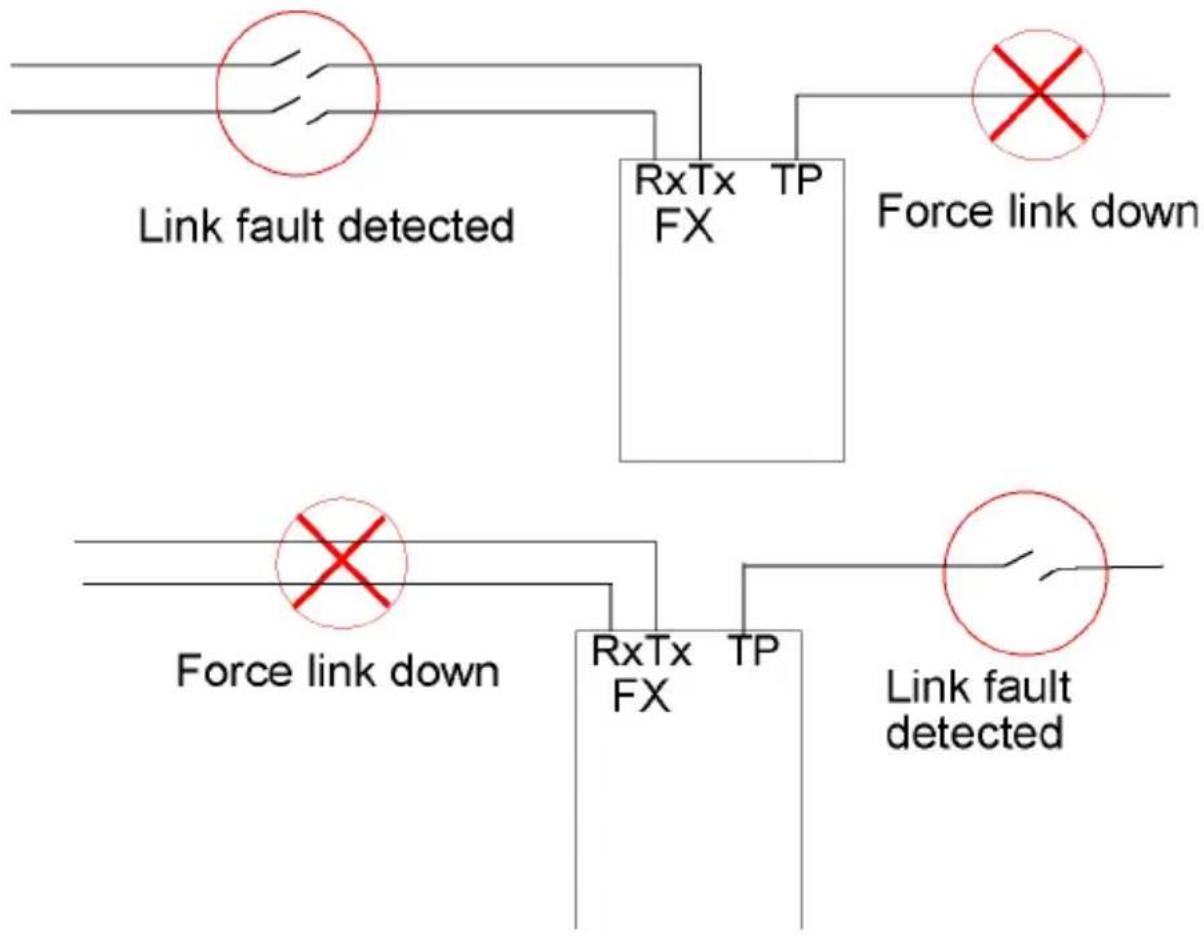
This function supports a link fault detected on the TP port will force a link down on the FX port. Similarly, a link fault detected on the FX port will also force a link down on the TP port. As illustrated in the following figure, this function allows to pass TP link fault to the remote link partner and makes the converter like a TP cable extender.
flowchart
graph TD
    A["Link fault detected"] --> B["RxTx TP FX"]
    C["Force link down"] --> B
    D["Link fault detected"] --> E["RxTx TP FX"]
    F["Force link down"] --> E
    G["Link fault detected"] --> H["RxTx TP FX"]
    I["Force link down"] --> H
    J["Link fault down"] --> K["RxTx TP FX"]
2. Installation
2.1 Unpacking
Check that the following components have been included:
- Product CD
• 10/100 Media Converter - One AC power adapter
If any item is found missing or damaged, please contact your local reseller for replacement.
2.2 Mounting the Device
Desktop Mounting
The media converter can be mounted on a desktop or shelf. Make sure that there is proper heat dissipation from and adequate ventilation around the device. Do not place heavy objects on the device.
Wall Mounting
The media converter also can be mounted on a wall. On bottom of the device, wall mounting hole is provided for wall mounting.
Installation into Center Chassis
The media converter also can be installed in a center chassis. The center chassis provides the power supply to the converter. Up to 16 units can be installed in one chassis. Unscrew and remove the cover of the center connector before inserting the converter into the chassis.
2.3 Applying Power
Before you begin the installation, check the AC voltage of your area. The AC power adapter which is used to supply the DC power for the unit should have the AC voltage matching the commercial power voltage in your area.
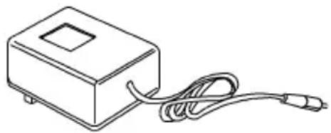
The AC Power Adapter Specifications
natural_image
Line drawing of a rectangular device with a coiled cable and a small square opening, connected to a terminal block (no text or symbols)AC input power: AC power voltage of your area, options -
Rated AC120V/60Hz DC7.5V 1A
Rated AC230V/50Hz DC7.5V 1A
Rated AC100V/50-60Hz DC7.5V 1A
Rated AC100V/50-60Hz DC5V 1A
Rated AC240V/50Hz DC7.5V 1A
Steps to apply the power to the converters are:
- Connect power adapter DC plug to the DC input jack located on the back of the converter before connecting to the AC outlet.
- To ensure against accidental disconnection, tie the DC cable with the cable tie located the back of the converter.
- Connect the power adapter to the AC outlet.
- Check Power LED indication.
2.4 Making TP Port Connection
TP port is featured to support connection to :
• Auto-negotiation devices
• Auto-negotiation incapable 10BASE-T devices
• Auto-negotiation incapable 100BASE-TX devices
Network Cables
10BASE-T: 2-pair UTP Cat. 3,4,5, EIA/TIA-568 100-ohm STP
100BASE-TX: 2-pair UTP Cat. 5, EIA/TIA-568 100-ohm STP
Link distance: Up to 100 meters
2.5 Making FX Port Connection
FX port operates on 100Mbps and full duplex (factory default). A variety of fiber options is provided as follows:
Duplex Fiber Series
Model Connector Wavelength Fiber Max.distance
EM4000 SC 1310nm Duplex MMF 2km
EM4001 ST 1310nm Duplex MMF 2km
2.6 LED Indicators
LEDDisplay Status Interpretation
PWR Power status On Power on
Off Power off
TP LINK TP port link status On Link up and no traffic
Off Link fault
Blink Rx/Tx activities
TP 100M TP port speed status On 100Mbps
Off 10Mbps
TP FDX TP port duplex status On Full duplex
Off Half duplex
Blink Collisions on half duplex
FX LINK FX port link status On Link up and no traffic
Off Link fault
Blink Rx/Tx activities
FX OL FX port optical link On Optical signal is detected
Off No optical signal is detected
Link Fault Pass Through Function
TPLINK FXLINK FXOL Interpretation
On On On Both TP and FX ports link up
Off Off On (1) TP port link fault or
(2) FX port received FEFI signal
(FX port Tx path failed.)
Off Off Off (1) TP port link fault or
(2) FX port Rx link failure detected
2.7 Smart Forwarding
The media converters are featured with a smart forwarding design. The following table lists the forward method used in different TP to FX conversions:
TP port to/from FX port Forward method
10BASE-T to 100BASE-FX Store and forward 100BASE-TX to 100BASE-FX Direct conversion
The converter can change to direct conversion automatically when it detects same speed on both TP port and FX port. Direct conversion method converts the signal between TP port and FX port without storing the received packet on one port then forwarding to another port. The media converter operates with the minimum latency.
Note:
- In direct conversion, be sure both devices connected to the TP port and FX port have same duplex mode for proper transmission.
- In direct conversion, 802.3x function is disabled and the media converter will not generate pause frame, but just forwards the received pause frame directly from one port to another port.
- In direct conversion, the media converter is not limited to the maximal length of the receiving packets.