
CEN-IDOCV-DSW-B-T - Support voiture Crestron - Free user manual and instructions
Find the device manual for free CEN-IDOCV-DSW-B-T Crestron in PDF.


| Product Type | Vehicle Mount/Docking Station |
| Brand | Crestron |
| Model | CEN-IDOCV-DSW-B-T |
| Dimensions (approx.) | 200 x 150 x 50 mm (7.9 x 5.9 x 2.0 in) |
| Weight (approx.) | 0.5 kg (1.1 lb) |
| Power Input | 12V DC from vehicle power (cigarette lighter adapter included) |
| Power Output to Device | USB-C or proprietary connector (up to 15W) |
| Main Function | Secure mounting and charging of compatible Crestron tablet or control device |
| Adjustable Viewing Angle | Yes, tilt and swivel |
| Locking Mechanism | Key lock to prevent theft |
| Compatible Devices | Crestron TSW series and similar tablets |
| Installation | Clip-on or screw mount to vehicle seat rail or floor |
| Maintenance | Wipe with a dry or slightly damp cloth; do not use solvents |
| Safety | Use only with approved devices; do not obstruct airbags |
| Spare Parts Available | Mounting brackets, screws, power cable |
| Repairability | Modular design; contact Crestron support for service |
| Operating Temperature | 0°C to 40°C (32°F to 104°F) |
Frequently Asked Questions - CEN-IDOCV-DSW-B-T Crestron
User questions about CEN-IDOCV-DSW-B-T Crestron
0 question about this device. Answer the ones you know or ask your own.
Ask a new question about this device
Download the instructions for your Support voiture in PDF format for free! Find your manual CEN-IDOCV-DSW-B-T - Crestron and take your electronic device back in hand. On this page are published all the documents necessary for the use of your device. CEN-IDOCV-DSW-B-T by Crestron.
USER MANUAL CEN-IDOCV-DSW-B-T Crestron
Crestron CEN-IDOCV-DSW
Wall Mount Interface for Apple® iPod®
Operations & Installation Guide
This document was prepared and written by the Technical Documentation department at:

CRESTRON®
Crestron Electronics, Inc.
15 Volvo Drive
Rockleigh, NJ 07647
1-888-CRESTRON
Industry Compliance
The PWE-4803RU is Listed to applicable UL Standards and requirements by Underwriters Laboratories Inc.

(E300305)
As of the date of manufacture, the CEN-IDOCV-DSW and PWE-4803RU have been tested and found to comply with specifications for CE marking and standards per EMC and Radiocommunications Compliance Labelling.


Federal Communications Commission (FCC) Compliance Statement
This device complies with part 15 of the FCC rules. Operation is subject to the following conditions: (1) this device may not cause harmful interference and (2) this device must accept any interference received, including interference that may cause undesired operation.
CAUTION: Changes or modifications not expressly approved by the manufacturer responsible for compliance could void the user's authority to operate the equipment.
NOTE: This equipment has been tested and found to comply with the limits for a Class B digital device, pursuant to part 15 of the FCC rules. These limits are designed to provide reasonable protection against harmful interference in a residential installation. This equipment generates, uses and can radiate radio frequency energy and if not installed and used in accordance with the instructions, may cause harmful interference to radio communications. However, there is no guarantee that interference will not occur in a particular installation. If this equipment does cause harmful interference to radio or television reception, which can be determined by turning the equipment off and on, the user is encouraged to try to correct the interference by one or more of the following measures:
• Reorient or relocate the receiving antenna
- Increase separation between the equipment and the receiver
- Connect the equipment into an outlet on a circuit different from that to which the receiver is connected
- Consult the dealer or an experienced radio/TV technician for help

Made for
iPod
Contents
CEN-IDOCV-DSW Quick Start iii
Introduction ......iii
Required Equipment....iii
Installation....iii
Wall Mount Interface for Apple ^® iPod ^® : CEN-IDOCV-DSW 1
Introduction .... 1
Features and Functions....1
Applications....4
Specifications 5
Physical Description....7
Setup....11
Network Wiring....11
CAT5 Wiring....11
Identity Code....12
Installation....12
Hardware Hookup 14
Programming Software....18
Earliest Version Software Requirements for the PC 18
Programming with Crestron SystemBuilder....18
Programming with SIMPL Windows....18
Example Program....20
Uploading and Upgrading....21
Establishing Communication....21
Programs and Firmware 22
Program Checks 22
Problem Solving 24
Troubleshooting....24
Reference Documents....25
Further Inquiries....25
Future Updates ....25
Appendix: PoE Injector – PWE-4803RU 26
Specifications 26
Physical Description....27
Setup....29
Return and Warranty Policies....30
Merchandise Returns / Repair Service 30
CRESTRON Limited Warranty....30
CEN-IDOCV-DSW Quick Start
Introduction
The following steps are designed to guide you through the basic hookup, configuration and use of a CEN-IDOCV-DSW. For detailed instructions on installation and usage, please refer to “Wall Mount Interface for Apple® iPod®: CEN-IDOCV-DSW” on page 1.
Required Equipment
The following equipment is required to load and run the demo program.
• Power over Ethernet injector such as the Crestron PWE-4803RU.
- CEN-IDOCV-DSW Wall Mount Interface for Apple ^ iPod ^ .
- 2-Series control system with CUZ file version 3.155 or later.
- Apple iPod ^® . 1, 2, 3
- USB cable for connecting CEN-IDOCV-DSW to PC.
- Optional: ABAR-1 or ABVR-1.
- For a complete list of supported products, refer to Crestron Online Help Answer ID 4837, or contact Crestron True Blue Support at www.crestron.com/truc_blue_support.
- Except where noted, this document uses the term "iPod" as a general reference to the various versions of iPod produced by Apple Computer, Inc.
- iPod device not included.
Installation
Refer to the following diagrams and connect the CEN-IDOCV-DSW in the following order.
- Connect AUDIO OUT to a device capable of receiving Crestron Home ^® (CH) audio (i.e. ABAR-1).
AUDIO OUT Port
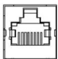
AUDIO OUT
- If video is to be delivered from the CEN-IDOCV-DSW, connect VIDEO OUT to a device capable of receiving CH video (i.e. ABVR-1).
VIDEO OUT Port
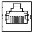
VIDEO OUT
- Connect the LAN PoE port to a PoE Injector or other PoE source.
LAN PoE Port
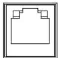
LAN PoE
-
Mount the CEN-IDOCV-DSW using the four included mounting screws, attach the plastic door using the supplied screw and a 1/16" Allen wrench. Refer to "CEN-IDOCV-DSW Mounting" on page 12 for details.
-
Program the Crestron ^® system using either:
-
Standard programming methods such as creating a custom program in SIMPL™ Windows or Crestron SystemBuilder™.
-
Use the example program available from the Crestron website (www.crestron.com/exampleprograms) as the foundation for a program containing a CEN-IDOCV-DSW.
-
Establish communications with the CEN-IDOCV-DSW. Refer to "Establishing Communication" on page 21 for details.
-
Configure the CEN-IDOCV-DSW to connect with the network control system.
a. DHCP is on by default.
b. Connect via USB as described on page 21.
c. Display the CEN-IDOCV-DSW's "System Info" window (click the
Icon) to view and note the IP address (to be used in step 10d on the following page).
d. Configure the IP table (this enables communication with the control system).
-
Upload and test the program created in step 5. Refer to “Programs and Firmware” on page 22 for more information.
-
Install and configure Crestron Sync for iTunes on the PC or Mac hosting iTunes ^® . Crestron Sync is available for download from the Crestron website (www.crestron.com/crestronsync). Follow the instructions to download and configure the software.
a. Setup all CEN-IDOCV-DSW addresses in Crestron Sync (this should not be done by the end user). Refer to "Install & Configure Crestron Sync for iTunes Software" on page 15 and the Crestron Sync help file for more information.
b. If the "Add New Device" window is not automatically displayed after starting Crestron Sync for the first time, right-click inside the "Crestron Sync" window and click Add New Device.
c. Enter a name for the device, i.e., My iPod (This is not the name of the iPod. It is a reference name to help the user identify the CEN-IDOCV-DSW).
d. Type the IP address of the CEN-IDOCV-DSW (from step 8 on the previous page).
e. Click OK to add the device to the "Crestron Sync" window.
f. Connect an iPod to the CEN-IDOCV-DSW by placing the iPod into the CEN-IDOCV-DSW's docking station.
g. Test a sync operation. If syncing a large library with an empty iPod, the iPod should be removed from the CEN-IDOCV-DSW and directly connected to the PC hosting iTunes. Subsequent minor updates can be done with the iPod in the CEN-IDOCV-DSW using the Crestron Sync application.
- Leave the latest version of the Crestron CEN-IDOCV-DSW Quick Start Guide (Doc. 6828) with the end user.
This concludes the Quick Start section of the CEN-IDOCV-DSW Operations Guide. Continue reading for more information on installing and operating the CEN-IDOCV-DSW.
Wall Mount Interface for Apple® iPod®: CEN-IDOCV-DSW
Introduction
The CEN-IDOCV-DSW provides an interface and control solution for the popular Apple ^® iPod ^® personal media player ^1,2,3 in an elegant flush wall mount design. It features a built-in, recessed docking station with audio, video, USB, and high-speed Ethernet connectivity for full integration with a Crestron ^® whole-house AV system ^4 .
The CEN-IDOCV-DSW uses the latest Apple authentication chip, enabling high speed music library browsing and compatibility with the latest Apple products and features. The chip supports 6^th generation (and later) iPod Classic, and late model iPod nano, iPhone, and iPod touch ^1 .
Features and Functions
- "Made for iPod" AV and control interface
• Stylish in-wall docking station - Enables full 2-way touchpanel control of the iPod
- Displays metadata and album cover art ^5
- Plays audio throughout the home or office ^4
- Allows viewing of video files on a video touchpanel or display ^4
- Syncs to iTunes ^® over Ethernet
• Charges the iPod battery - Allows local navigation and volume control
- Includes Crestron Home ^ CAT5 Balanced AV connectivity
- Affords plug-and-play integration with Adagio ^ systems
-
PoE network powered
• Available in white or black -
For a complete list of supported products, refer to Crestron Online Help Answer ID 4837, or contact Crestron True Blue Support at www.crestron.com/true_blue_support.
- Except where noted, this document uses the term "iPod" as a general reference to the various versions of iPod produced by Apple Computer, Inc.
- iPod device not included.
- Audio/video signal output requires one or more Crestron Home ^ (CH) CAT5 balanced AV compatible devices.
- Display of album cover art is currently only supported using the iPod ^ touch model.
The CEN-IDOCV-DSW is available in four different models.
Models
| DESCRIPTION | MODEL | NUMBER | COL |
| iPod®with Video | CEN-IDOCV-DSW-B-T | Black Wall Mount Interface for Apple | |
| CEN-IDOCV-DSW-W-T | White | ||
| iPod®with Video, with PoE Injector | CEN-IDOCV-DSW-PWE-B-T | Black Wall Mount Interface for Apple | |
| CEN-IDOCV-DSW-PWE-W-T | White |
For simplicity within this guide, the color and packaged accessories are omitted and CEN-IDOCV-DSW is used except where noted.
Easy Docking
Placing the iPod into the docking station instantly connects it for sharing with speakers and video monitors throughout the home or office.
Touchpanel Control
Integrating the iPod with a Crestron system enables full control and navigation using touchpanels, APADs, keypads, computers, and handheld remotes. From any touchpanel, you can search the entire iPod library by genre, artist, album and track, and even view album cover art ^1 .
- Display of album cover art is currently only supported using the iPod ^® touch model.
Local Controls
Press the LOCAL button on the front of the CEN-IDOCV-DSW to allow navigation control directly on the iPod device without undocking. Volume control is also enabled using the VOL rocker button, so it is not necessary to install a separate touchpanel or keypad nearby just to control the iPod.
Sync to iTunes ^® over Ethernet
Using USB-over-IP technology and Crestron Sync, the CEN-IDOCV-DSW allows the iPod to connect with any networked computer running Apple iTunes software right from the docking station. Syncing the iPod to iTunes works the same as if it were hooked up with a USB cable, affording full capabilities for organizing and transferring music and video files, podcasts, audio books, and playlists anytime you want.
Audio and Video Distribution ^2
The CEN-IDOCV-DSW allows stereo audio, composite video, and component video signals to be fed from the iPod to your home theater or multiroom distribution system.
- Audio/video signal output requires one or more Crestron Home ^® (CH) CAT5 balanced AV compatible devices.
Crestron Home® CAT5 Balanced AV
Crestron Home (CH) CAT5 Balanced technology allows the CEN-IDOCV-DSW to be located up to 500 feet (152 meters) from the central equipment, interfacing directly with other CH-compatible devices like the Crestron CNX-BIPAD8 and CNX-PVID8 using ordinary CAT5 type wire. Connecting the CEN-IDOCV-DSW to conventional AV equipment, or to a Crestron Adagio ^® Home Entertainment system, is facilitated using the ABAR-1 Balanced Audio Receiver and ABVR-1 Balanced Video Receiver (both sold separately).
Adagio ^® Plug-and-Play
The CEN-IDOCV-DSW affords easy plug-and-play setup as part of a complete Adagio system. Without any programming, Adagio delivers full access and control of the docked iPod from every room.
Power over Ethernet
For operation and charging the iPod battery, the CEN-IDOCV-DSW gets its power right through the LAN wiring using 802.3af PoE technology. PoE (Power over Ethernet) eliminates the need for a separate wall-wart power supply or dedicated power wiring. A PoE Injector (PWE-4803RU optional) simply connects inline with the LAN cable, allowing for installation at any convenient location. For applications with multiple CEN-IDOCV-DSWs or other PoE-powered devices, a Crestron 5-port PoE switch (CEN-SW-POE-5, sold separately) may be used, allowing up to four devices to be powered from a single location.
Versatile Wall Mount Design
The CEN-IDOCV-DSW is designed for easy recess-mount installation in a wall or similar flat, vertical surface using one of two available mounting kits (sold separately). The mounting options include the BB-IDOCV-DSW back box, and the WMK-BB-IDOCV-DSW post-construction mounting kit.
Applications
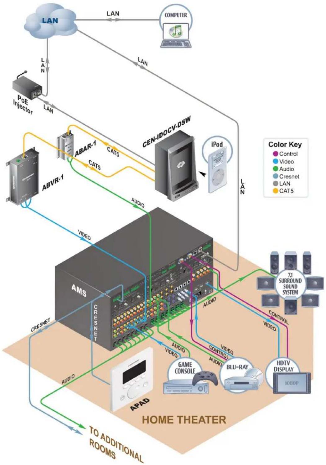
The following diagram shows a CEN-IDOCV-DSW in a residential application.
CEN-IDOCV-DSW in a Residential Application
flowchart
graph TD
    A["LAN"] -->|LAN| B["COMPUTER"]
    B -->|LAN| C["CEN-IDOCV-DSW"]
    C -->|LAN| D["POS"]
    D -->|LAN| E["POE Injector"]
    E -->|LAN| F["ABVR-1"]
    F -->|AUDIO| G["AMS"]
    G -->|VIDEO| H["7J SURROUND SOUND SYSTEM"]
    H --> I["CONTROL"]
    I --> J["HDTV DISPLAY"]
    J --> K["IOBOP"]
    K --> L["BLU-RAY"]
    L --> M["Audio"]
    M --> N["Video"]
    N --> O["Audio"]
    O --> P["CAPS"]
    P --> Q["AMPS"]
    Q --> R["APAD"]
    R --> S["TO ADDITIONAL ROOMS"]
    S --> T["Apad"]
    T --> U["Game Console"]
    U --> V["Video"]
    V --> W["Video"]
    W --> X["Audio"]
    X --> Y["Video"]
    Y --> Z["Audio"]
    Z --> AA["Video"]
    AA --> AB["Audio"]
    AB --> AC["Video"]
    AC --> AD["Audio"]
    AD --> AE["Video"]
    AE --> AF["Audio"]
    AF --> AG["Video"]
    AG --> AH["Audio"]
    AH --> AI["Video"]
    AI --> AJ["Audio"]
    AJ --> AK["Video"]
    AK --> AL["Audio"]
    AL --> AM["Video"]
    AM --> AN["Audio"]
    AN --> AO["Video"]
    AO --> AP["Audio"]
    AP --> AQ["Video"]
    AQ --> AR["Audio"]
    AR --> AS["Video"]
    AS --> AT["Audio"]
    AT --> AU["Video"]
    AU --> AV["Audio"]
    AV --> AW["Video"]
    AW --> AX["Audio"]
    AX --> AY["Video"]
    AY --> AZ["Audio"]
    AZ --> BA["Video"]
    BA --> BB["Audio"]
    BB --> BC["Video"]
    BC --> BD["Audio"]
    BD --> BE["Video"]
    BE --> BF["Audio"]
    BF --> BG["Video"]
    BG --> BH["Audio"]
    BH --> BI["Video"]
    BI --> BJ["Audio"]
    BJ --> BK["Video"]
    BK --> BL["Audio"]
    BL --> BM["Video"]
    BM --> BN["Audio"]
    BN --> BO["Video"]
    BO --> BP["Audio"]
    BP --> BQ["Video"]
    BQ --> BR["Audio"]
    BR --> BS["Video"]
    BS --> BT["Audio"]
    BT --> BU["Video"]
    BU --> BV["Audio"]
    BV --> BW["Video"]
    BW --> BX["Audio"]
    BX --> BY["Video"]
    BY --> BZ["Audio"]
    BZ --> CA["Video"]
    CA --> CB["Audio"]
    CB --> CC["Video"]
    CC --> CD["Audio"]
    CD --> CE["Video"]
    CE --> CF["Audio"]
    CF --> CG["Video"]
    CG --> CH["Audio"]
    CH --> CI["Video"]
    CI --> CJ["Audio"]
    CJ --> CK["Video"]
    CK --> CL["Audio"]
Specifications
Specifications for the CEN-IDOCV-DSW are listed in the following table.
CEN-IDOCV-DSW Specifications
| SPECIFICATION | DETAILS |
| Compatibility^1 | |
| iPod | For a complete list of supported products, refer to Crestron Online Help Answer ID 4837, or contact Crestron True Blue Support at www.crestron.com/true_blue_support. |
| Computer | Crestron Sync software is compatible with Mac OS X v1.5, Windows XP, and Windows Vista |
| Signal Types^2 | |
| Audio | Analog stereo output via Crestron 'CH' CAT5 Balanced Audio port |
| Video | Composite and Component (YP _B Pr) outputs via Crestron 'CH' CAT5 Balanced Video port |
| Ethernet | 10Base-T/100Base-TX, static IP or DHCP, DNS, full duplex, auto-switching, auto-negotiating, auto-discovery, TCP/IP, CIP, IEEE 802.3u & 802.3af compliant |
| Power over Ethernet IEEE 802.3af Class 2 PoE Powered Device | |
| Default IP ID 03 | |
| Minimum 2-Series Control System Update File^3,4 | Version 3.155 or later |
| Environmental | |
| Temperature 41° to 113° F (5° to 45 °C). | |
| Humidity 10% to 90% RH (non-condensing) | |
| Heat Dissipation 14 BTU/Hr | |
| Enclosure | Injection-molded plastic; requires BB-IDOCV-DSW or WMK-BB-IDOCV-DSW wall mounting kit (sold separately) |
| Dimensions | |
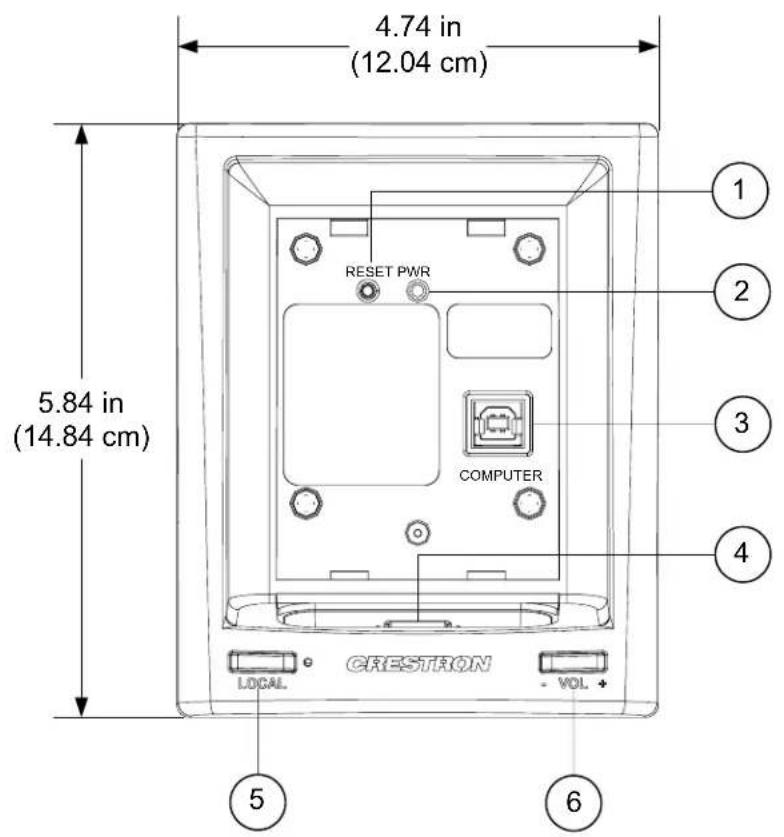
| Height 5.84 in (14.84 cm) | |
| Width 4.74 in (12.04 cm) | |
| Depth 3.09 in (7.85 cm) | |
| Weight 0.8 lb (13 oz) | |
| Included Accessories^5 | |
| PWE-4803RU | PoE Injector (Included with CEN-IDOCV-DSW-PWE models only) |
| Available Accessories | |
| ABAR-1 CAT5 Balanced Audio Receiver | |
| ABVR-1 CAT5 Balanced Video Receiver | |
| BB-IDOCV-DSW Wall Mount Back Box | |
| CEN-SW-POE-5 5-Port PoE Switch | |
| CNX-PBAR4 Quad CAT5 Balanced Audio Receiver | |
| CNX-PBVR4 Quad CAT5 Balanced Video Receiver | |
| PWE-4803RU | PoE Injector (Included with CEN-IDOCV-DSW-PWE models) |
| WMK-BB-IDOCV-DSW Post-Construction Mounting Kit | |
-
iPod device not included.
-
Audio/video signal output requires one or more Crestron Home (CH) CAT5 Balanced AV compatible devices.
-
The latest software versions can be obtained from the Crestron website. Refer to the NOTE following these footnotes.
-
Crestron 2-Series control systems include the AV2 and PRO2. Consult the latest Crestron Product Catalog for a complete list of 2-Series control systems.
-
Refer to separate product specifications for additional details.
NOTE: Crestron software and any files on the website are for authorized Crestron dealers and Crestron Authorized Independent Programmers (CAIP) only. New users may be required to register to obtain access to certain areas of the site (including the FTP site).
Physical Description
This section provides information on the connections and controls available on your CEN-IDOCV-DSW.
CEN-IDOCV-DSW Physical View
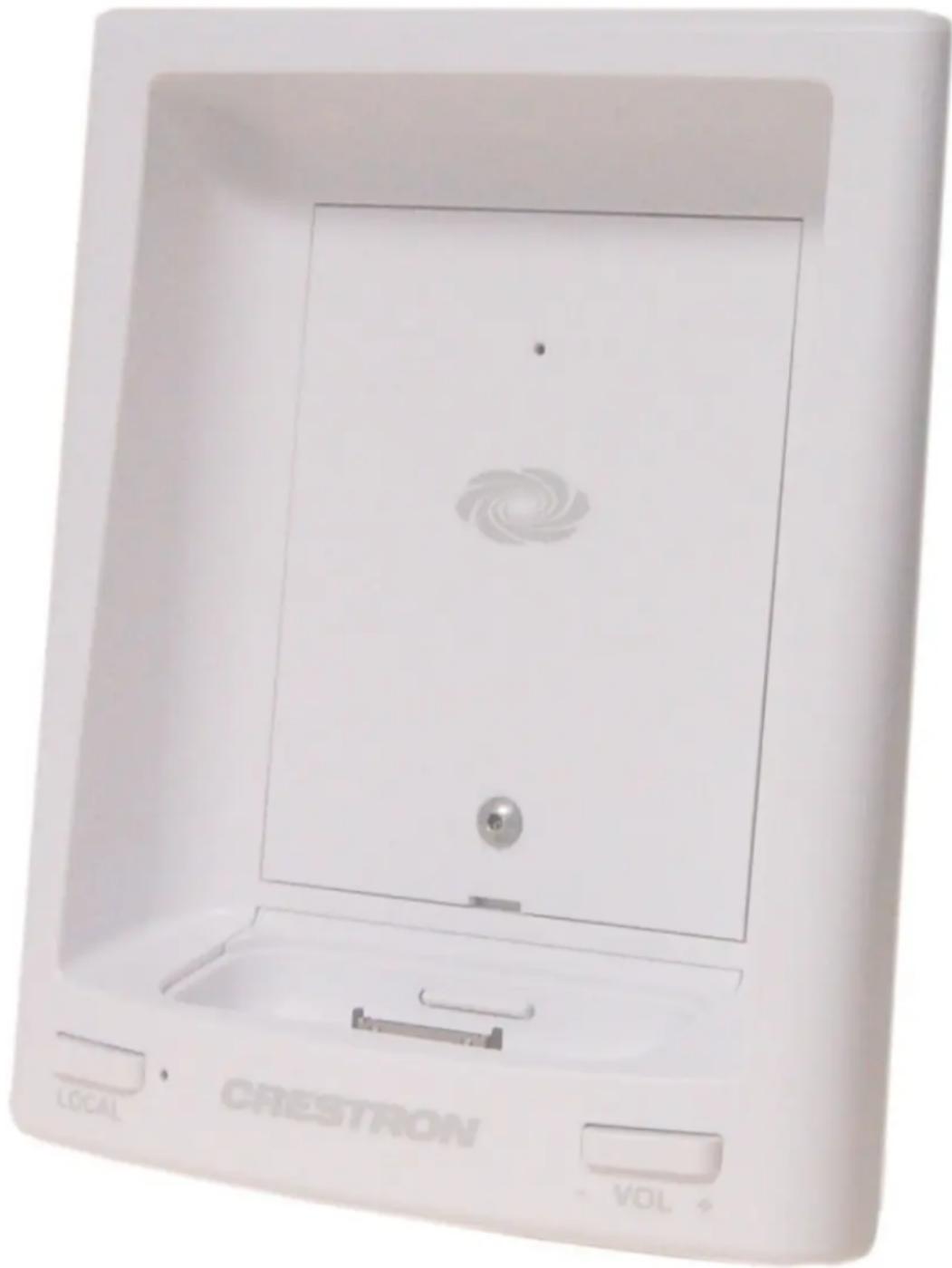
natural_image
White rectangular device with a spiral pattern on the front panel, labeled 'CRESTRON' and 'LOCAL' at the bottom (no readable text beyond labels)CEN-IDOCV-DSW Overall Dimensions (Front and Side View)
text_image
4.74 in (12.04 cm) 5.84 in (14.84 cm) RESET PWR COMPUTER LOCAL VOL ① ② ③ ④ ⑤ ⑥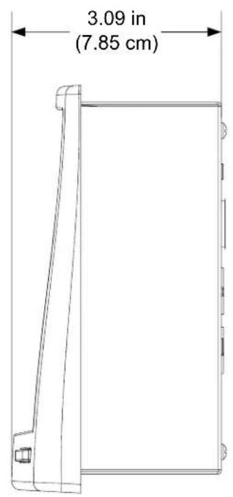
text_image
3.09 in (7.85 cm)CEN-IDOCV-DSW Overall Dimensions (Rear View)
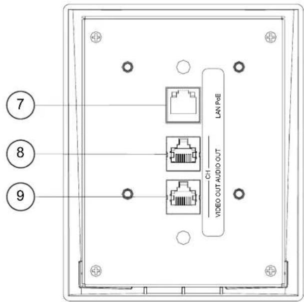
text_image
7 8 9 LAN P&E CH VIDEO OUT AUDIO OUTConnectors, Controls & Indicators
| # | CONNECTORS,CONTROLS &INDICATORS | DESCRIPTION |
| 1 | RESET Pushbutton | (1) Recessed miniature pushbutton behindfront cover for hardware reset |
| 2 PWR LED | (1) Green LED behind front cover, indicatespower supplied from PoE | |
| 3 | COMPUTER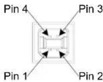 | (1) USB Type B female behind front coverLocated in docking bay behind faceplateUSB 2.0 port (cable included) |
| PIN DESCRIPTION | ||
| 1 +5 VDC2 Data -3 Data +4 Ground | ||
| 4 Docking Port | Accepts standard Apple dock adapters(not included)Provides 2-way communications, audio,video, and power link to iPod | |
| 5 | LOCAL (Pushbuttonand LED) ^1,2 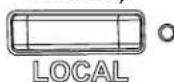 | (1) Pushbutton & green LED, enables localcontrol mode using the iPod user interfaceGreen LED indicates that iPod may becontrolled through its user interface |
| 6 | VOL^2,3  | (1) Programmable rocker button for up/downvolume control |
| 7 | LAN PoE^4 GREEN YELLOWLED LED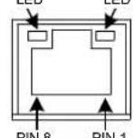 | (1) 8-wire RJ-45 with two LED indicators;10Base-T/100Base-TX Ethernet port,802.3af Power over Ethernet compliant;Green LED indicates link status;Yellow LED indicates Ethernet activity |
| 8 | CH AUDIO OUT ^5 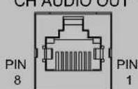 | (1) 8-wire RJ-45 female, shielded;CAT5 balanced stereo audio output port;Connects to any “CH” CAT5 audio input portor bidirectional audio port;Maximum Cable Length: 500 ft (152 m) |
| 9 | VIDEO OUT^6 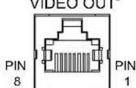 | (1) 8-pin RJ-45 female, shielded;CAT5 balanced video output port;Formats: Composite, component ( YP_bP_r );Connects to any “CH” CAT5 video input port;Maximum Cable Length: 500 ft (152 m) |
- To control an iPod that is not on the list of compatible devices, press the LOCAL pushbutton to enable local control mode. The iPod is then controlled through the iPod user interface.
- Volume can only be controlled from the VOL rocker button.
-
iPod always outputs line-level audio. The VOL rocker button controls volume through digital presses that are sent to a control system or other volume control devices such as a CNX-PAD8A.
-
Refer to the following table for connector pinouts. DC power applied by Ethernet power sourcing equipment (PSE) can connect to either signal pins or N/C pins.
| PIN SIGNAL | |
| 1 TX+ | |
| 2 TX- | |
| 3 RC+ | |
| 4 N/C | |
| 5 | N/C |
| 6 RC- | |
| 7 | N/C |
| 8 N/C | |
- This eight-pin RJ-45 port provides connectivity to the CNX-BIPAD or a Crestron device with a CAT5 audio input. This port provides stereo output over CAT5 wiring. Refer to the following table for connector pinouts.
| PIN | WIRE COLORS(568B) | AUDIO I/O |
| 1 | WHITE/ORANGE + Audio Left Out | |
| 2 | ORANGE - Audio Left Out | |
| 3 | WHITE/GREEN + Audio Right Out | |
| 4 | BLUE N/A | |
| 5 | WHITE/BLUE | N/A |
| 6 | GREEN | - Audio Right Out |
| 7 | WHITE/BROWN | N/A |
| 8 | BROWN | N/A |
- This eight-pin RJ-45 port provides connectivity to a device with a CII input port or a Crestron device with a CAT5 video input. This port provides component or composite balanced output over CAT5 wiring. Refer to the following table for connector pinouts.
| PIN | WIRE COLORS (568B) | COMPOSITE | COMPONENT |
| 1 | WHITE/ORANGE | + Composite | + Y |
| 2 | ORANGE | - Composite | - Y |
| 3 | WHITE/GREEN | N/A | + P_b |
| 4 | BLUE | N/A | + P_r |
| 5 | WHITE/BLUE | N/A | - P_r |
| 6 | GREEN | N/A | - P_b |
| 7 | WHITE/BROWN | N/A | N/A |
| 8 | BROWN | N/A | N/A |
Setup
Network Wiring
When wiring the Ethernet network, consider the following:
- Use Crestron Certified Wire.
- Use Crestron power supplies for Crestron equipment.
- Provide sufficient power to the system.
CAUTION: Insufficient power can lead to unpredictable results or damage to the equipment. Please use the Crestron Power Calculator to help calculate how much power is needed for the system (www.crestron.com/calculators).
Unlike other Crestron network devices, the CEN-IDOCV-DSW does not use Cresnet ^® for communications between the device and the control system. The CEN-IDOCV-DSW requires the use of a high-speed Ethernet connection for control system communications.
For information on connecting Ethernet devices in a Crestron system, refer to the latest version of the Crestron e-Control ^® Reference Guide (Doc. 6052), which is available from the Crestron website (www.crestron.com/manuals).
CAT5 Wiring
Category 5 (CAT5) wiring is a twisted pair cable designed for Ethernet networks. These networks operate at speeds of up to 100 Megabits per second (Mbps) using the 100BASE-T standard. Crestron takes advantage of this specification for a variety of audio and video applications.
Crestron recommends using CresCAT-IM (or D) wire for transmitting video signals from the CH port.
When using a Crestron wiring solution, the CresCAT-IM (or D) wire can carry audio and video signals up to 500 feet (152 meters) (observe distance limitations based upon power consumption for the device in use).
For more information, refer to the latest version of the Crestron CAT5 Wiring Reference Guide (Doc. 6137), which is available from the Crestron website.
Identity Code
The IP ID is set within the CEN-IDOCV-DSW's IP table using Crestron Toolbox. For information on setting an IP table, refer to the Crestron Toolbox help file. The IP IDs of multiple CEN-IDOCV-DSW devices in the same system must be unique.
When setting the IP ID, consider the following:
- The IP ID of each unit must match an IP ID specified in the SIMPL™ Windows program.
- Each device using IP to communicate with a control system must have a unique IP ID.
Installation
The CEN-IDOCV-DSW installs simply and cleanly into existing or newly constructed walls by using the pre-construction wall mount back box (BB-IDOCV-DSW) or the post-construction mounting kit (BB-WMK-IDOCV-DSW, both not supplied).
NOTE: Pre-construction refers to framed walls prior to hanging drywall or paneling. Post-construction refers to framed walls with drywall or paneling hung.
CEN-IDOCV-DSW Mounting
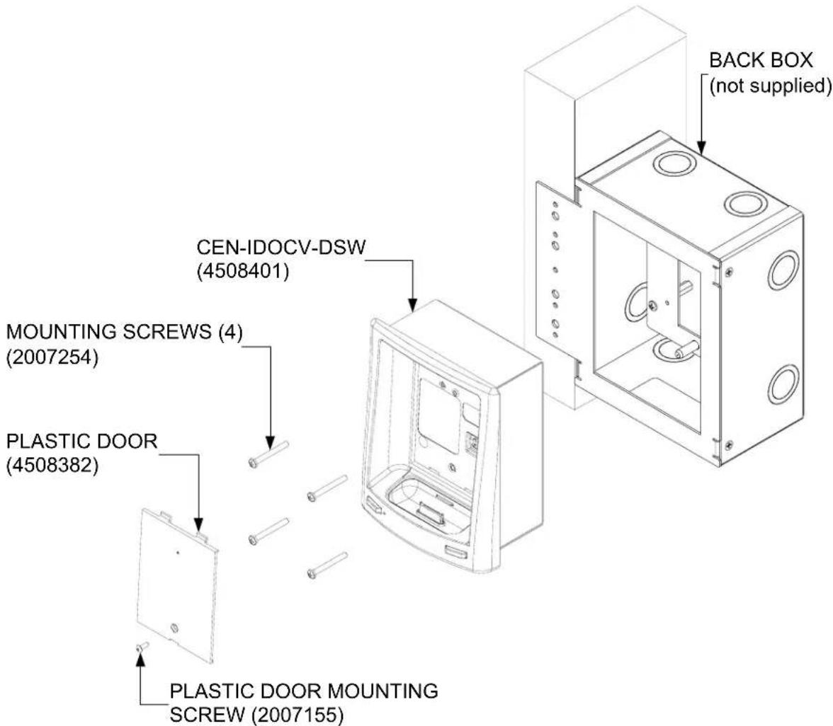
The only tools required (not supplied) is a #2 Phillips tip screwdriver and 1/16" Allen wrench. Refer to the image on the following page for visual guidance.
- If a metal cover plate is being used to cover an opening in the wall, use a #2 Phillips screwdriver to loosen and remove the four screws and the metal cover plate.
- Connect all required cables to the CEN-IDOCV-DSW. Refer to "Hardware Hookup" which starts on page 14 for details.
- Insert the CEN-IDOCV-DSW (with its plastic door removed) into the mounting option and align the four screw holes.
- Insert and tighten the four supplied screws (finger tight and use a #2 Phillips screwdriver, tighten an additional 1/8-turn).
- Cover the mounted unit with the plastic door. Using the 1/16" Allen wrench tighten the plastic door mounting screw.
Mounting the CEN-IDOCV-DSW with the BB-IDOCV-DSW
text_image
BACK BOX (not supplied) CEN-IDOCV-DSW (4508401) MOUNTING SCREWS (4) (2007254) PLASTIC DOOR (4508382) PLASTIC DOOR MOUNTING SCREW (2007155)CEN-IDOCV-DSW Removal
If it is necessary to remove the CEN-IDOCV-DSW after it has been installed, complete the following steps in the order provided to remove the unit. The only tool required is a #2 Phillips tip screwdriver and 1/16" Allen wrench.
- Remove the plastic door by loosening and removing the screw that holds the plastic door with the 1/16" Allen wrench.
- Loosen and remove the screws that secure the CEN-IDOCV-DSW to the mounting surface with the #2 Phillips tip screwdriver.
- Carefully remove the CEN-IDOCV-DSW from the mounting surface.
- If necessary, secure and label the attached cables before disconnecting them from the back of the unit.
Hardware Hookup
Connect the Device
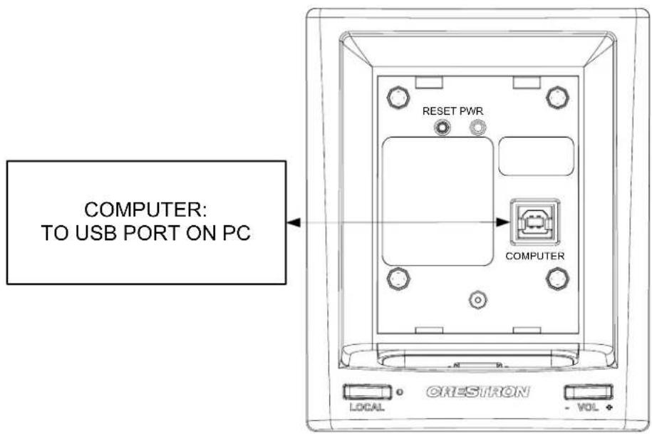
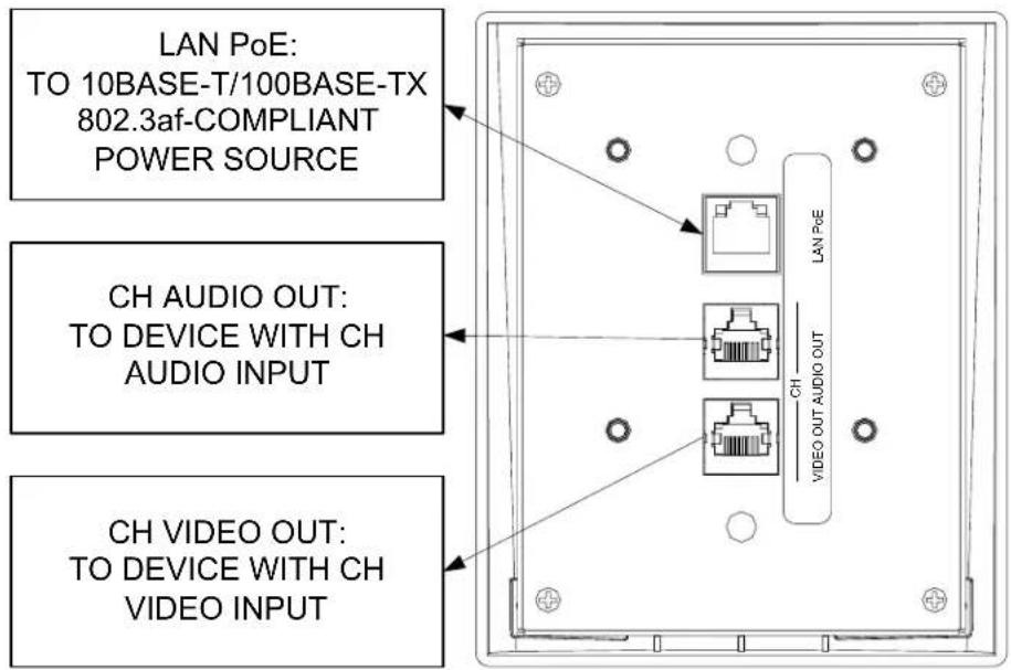
Make the necessary connections as called out in the illustration that follows this paragraph. Refer to "Network Wiring" on page 11 before attaching the LAN PoE cable. Apply power after all connections have been made.
When making connections to the CEN-IDOCV-DSW, use Crestron power supplies for Crestron equipment.
Hardware Connections for the CEN-IDOCV-DSW (Front View Shown with Door Removed)
text_image
COMPUTER: TO USB PORT ON PC RESET PWR COMPUTER LOCAL CRESTRON - VOLHardware Connections for the CEN-IDOCV-DSW (Rear View)
text_image
LAN PoE: TO 10BASE-T/100BASE-TX 802.3af-COMPLIANT POWER SOURCE CH AUDIO OUT: TO DEVICE WITH CH AUDIO INPUT CH VIDEO OUT: TO DEVICE WITH CH VIDEO INPUTConnect the iPod
After all the connections have been made to the CEN-IDOCV-DSW, and it has been properly mounted in a wall the iPod can be placed in the docking port of the wall mount interface.
NOTE: Due to the bandwidth limitations of a LAN, the CEN-IDOCV-DSW is not recommended for loading an empty iPod with a large music/video library. A direct USB connection between the iTunes PC and the iPod is highly recommended when loading an empty iPod with a large music/video library. After the iPod is loaded, the CEN-IDOCV-DSW should be used for regular syncing operations.
NOTE: Prior to connecting the iPod, the iPod's TV Out setting must be set to On, the TV Screen settings must be set to the aspect ratio of the connected display (16:9 or 4:3), the TV Signal setting must be set (NTSC or PAL), and the Fit to Screen setting must be set to Off. For instructions, refer to the iPod instruction manual.
Install & Configure Crestron Sync for iTunes Software
To complete the installation, Crestron Sync for iTunes (Crestron Sync) software must be installed and configured on the computer that contains the iTunes software. Crestron Sync can be configured to communicate with one or more CEN-IDOCV-DSWs in the system. Crestron Sync is available for download from the Crestron website (www.crestron.com/crestronsync). Instructions for using Crestron Sync can be found in the help file.
NOTE: Crestron Sync software is compatible with Mac OS ^® X v10.5, Windows XP Service Pack 2, and Windows Vista. Visit www.crestron.com/crestronsync for additional requirements.
NOTE: Crestron Sync software is not compatible with PowerPC ^TM computers.
NOTE (Mac Users): VMware, Parallels Desktop for Mac, and other virtualization software may cause connection issues with your iPod device and Crestron Sync software. To ensure proper operation, the system should be restarted using Mac OS X only.
NOTE: An iPod that is formatted on an Apple Macintosh ^® (Mac ^® ) computer will only sync with a Mac. An iPod that is formatted on a PC will sync with either a PC or Mac.
NOTE: If the CEN-IDOCV is on a local network and remote access is desired, then port forwarding for ports 41795 and 19540 needs to be enabled on the local and remote routers.
For PC:
- Open a web browser and go to www.crestron.com/crestronsync.
- Click on the appropriate link for the PC version of Crestron Sync.
- Click the link to download and install Crestron Sync software. Crestron Sync software will automatically start after installation.
- Configure Crestron Sync:
a. Right-click inside the "Crestron Sync" window and click Add New Device.
b. Enter a name for the device, i.e., My iPod (This is not the name of the iPod. It is a reference name to help the user identify the CEN-IDOCV-DSW).
If the device name is changed while connected to iTunes, this will disconnect the iPod. To re-connect, select the device and click Connect Selected.
c. Enter the IP address or hostname of the CEN-IDOCV-DSW.
NOTE: Once the IP address or hostname has been set within Crestron Sync it cannot be changed. If the IP address or hostname of the CEN-IDOCV-DSW changes, it must be removed from Crestron Sync and re-entered into the program.
d. Do not select the Automatically Connect check box. This control allows the user to select the Crestron device connection each time they start iTunes. If the check box is selected Crestron Sync will connect the device automatically each time iTunes starts or Crestron Sync starts.
c. Click OK to add the device to the "Crestron Sync" window.
- To add devices, re-open the "Add New Device" window and configure the additional devices as described in the instructions that start on page 15.
For Mac:
- Open a web browser and go to www.crestron.com/crestronsync.
- Click on the appropriate link for the Mac version of Crestron Sync.
- Click the link to download and install Crestron Sync software. Crestron Sync will not automatically add itself to Startup. This must be done manually one time.
- Configure Crestron Sync:
a. Run the application (Launch the Finder, Go to Applications, then double-click Crestron Sync icon).
b. Right-click (or Command + left-click) the application icon located in the Dock.
c. Click Open at Login.
d. If the “Add New Device” window is not automatically displayed upon starting Crestron Sync for the first time, right-click inside the “Crestron Sync” window and click Add New Device.
e. Enter a name for the device, i.e., My iPod (This is not the name of the iPod. It is a reference name to help the user identify the CEN-IDOCV-DSW).
If the device name is changed while connected to iTunes, this will disconnect the iPod. To re-connect, select the device and click Connect Selected.
f. Enter the IP address or hostname of the CEN-IDOCV-DSW.
NOTE: Once the IP address or hostname has been set within Crestron Sync it cannot be changed. If the IP address or hostname of the CEN-IDOCV-DSW changes, it must be removed from Crestron Sync and re-entered into the program.
g. Do not select the Automatically Connect check box. This control allows the user to select the Crestron device connection each time they start iTunes. If the check box is selected Crestron Sync will connect the device automatically each time iTunes starts or Crestron Sync starts.
h. Click OK to add the device to the "Crestron Sync" window.
- To add devices, re-open the "Add New Device" window and configure the additional devices as described in the instructions that start on page 16.
For more information, refer to the latest version of the CEN-IDOCV-DSW QuickStart Guide (Doc. 6828) which is available from the Crestron website or the Crestron Sync help file.
Programming Software
Have a question or comment about Crestron software?
Answers to frequently asked questions (FAQs) can be viewed in the Online Help section of the Crestron website. To post a question or view questions you have submitted to Crestron's True Blue Support, log in at www.crestron.com/support. First-time users will need to establish a user account.
Earliest Version Software Requirements for the PC
NOTE: Crestron recommends that you use the latest software to take advantage of the most recently released features. The latest software is available from the Crestron website.
Crestron has developed an assortment of Windows ^® -based software tools to develop a controlled system. You can create a program to control the CEN-IDOCV-DSW control system using the Crestron programming tools Crestron SystemBuilder ^™ or SIMPL Windows. For the minimum recommended software versions, visit the Version Tracker page of the Crestron website (www.crestron.com/versiontracker).
Programming with Crestron SystemBuilder
Crestron SystemBuilder is the easiest method of programming but does not offer as much flexibility as SIMPL Windows. For additional details, download SystemBuilder from the Crestron website and examine the extensive help file.
Programming with SIMPL Windows
NOTE: While SIMPL Windows can be used to program the CEN-IDOCV-DSW, it is recommended to use SystemBuilder for configuring a system.
SIMPL Windows is Crestron's premier software for programming Crestron control systems. It is organized into two separate but equally important "Managers".
Configuration Manager is the view where programmers “build” a Crestron control system by selecting hardware from the Device Library.
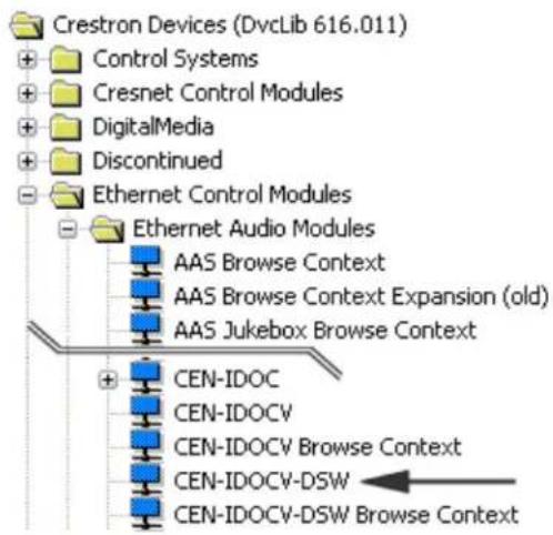
- To incorporate the CEN-IDOCV-DSW into the system, drag the CEN-IDOCV-DSW from the Ethernet Control Modules | Ethernet Audio Modules folder of the Device Library and drop it in the System Views.
Configuration Manager
Locating the CEN-IDOCV-DSW in the Device Library
text_image
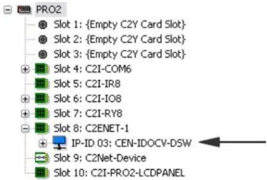
Crestron Devices (DvcLib 616.011) Control Systems Cresnet Control Modules DigitalMedia Discontinued Ethernet Control Modules Ethernet Audio Modules AAS Browse Context AAS Browse Context Expansion (old) AAS Jukebox Browse Context CEN-IDOC CEN-IDOCV CEN-IDOCV Browse Context CEN-IDOCV-DSW CEN-IDOCV-DSW Browse Context- The system tree of the control system displays the device in the appropriate slot with a default IP ID as shown in the following illustration.
C2Net Device, Slot 8
text_image
PRO2 Slot 1: {Empty C2Y Card Slot} Slot 2: {Empty C2Y Card Slot} Slot 3: {Empty C2Y Card Slot} Slot 4: C2I-COM6 Slot 5: C2I-IR8 Slot 6: C2I-IO8 Slot 7: C2I-RY8 Slot 8: C2ENET-1 IP-ID 03: CEN-IDOCV-DSW Slot 9: C2Net-Device Slot 10: C2I-PRO2-LCDPANEL• Additional CEN-IDOCV-DSW devices are assigned different IP ID numbers as they are added.
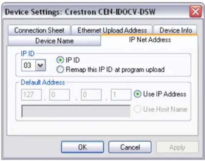
- If necessary, double click a device to open the "Device Settings" window and change the IP ID, as shown in the following figure.
"Device Settings: Crestron CEN-IDOCV-DSW" Window
text_image
Device Settings: Crestron CEN-IDOCV-DSW Connection Sheet Ethernet Upload Address Device Info Device Name IP Net Address IP ID 03 IP ID Remap this IP ID at program upload Default Address 127 0 0 1 Use IP Address Use Host Name OK Cancel Apply- The ID code specified in the SIMPL Windows program must match the IP ID of each unit. Refer to "Identity Code" on page 12.
Program Manager
Program Manager is the view where programmers "program" a Crestron control system by assigning signals to symbols.
The symbol can be viewed by double clicking on the icon or dragging it into Detail View. Each signal in the symbol is described in the SIMPL Windows help file (F1).
Example Program
An example program for the CEN-IDOCV-DSW is available from the Crestron website (www.crestron.com/examplecprograms).
Uploading and Upgrading
Crestron recommends using the latest programming software and that each device contains the latest firmware to take advantage of the most recently released features. However, before attempting to upload or upgrade it is necessary to establish communication. Once communication has been established, files (for example, programs or firmware) can be transferred to the control system (and/or device). Finally, program checks can be performed (such as changing the device ID or creating an IP table) to ensure proper functioning.
Establishing Communication
Use Crestron Toolbox for communicating with the CEN-IDOCV-DSW; refer to the Crestron Toolbox help file for details. There are two methods of communication.
USB
NOTE: Required for initial setup of Ethernet parameters.
USB Communication

flowchart
graph LR
    A["PC RUNNING CRESTRON TOOLBOX"] <-->|USB| B["CEN-IDOCV-DSW"]
The COMPUTER port on the CEN-IDOCV-DSW connects to the USB port on the PC via the included Type A to Type B USB cable:
- Connect the power-carrying Ethernet cable to the LAN PoE port to provide power to the CEN-IDOCV-DSW.
-
Use the Address Book in Crestron Toolbox to create an entry using the expected communication protocol (USB). When multiple USB devices are connected, identify the CEN-IDOCV-DSW by entering "CEN-IDOCV-DSW" in the Model textbox, the unit's serial number in the Serial textbox or the unit's hostname in the Hostname textbox. The hostname can be found in the "System Info" window in the section marked Ethernet however, communications must be established in order to see this information in the "System Info" window.
-
Display the CEN-IDOCV-DSW's "System Info" window (click the icon); communications are confirmed when the device information displayed.

TCP/IP/PoE
NOTE: Required for operation with a Crestron control system.
Ethernet Communication

flowchart
graph LR
    A["PC RUNNING CRESTRON TOOLBOX"] <--> B["POWER OVER ETHERNET"]
    B --> C["CEN-IDCV-DSW"]
The CEN-IDOCV-DSW connects to PC via Ethernet:
- Establish USB communication between CEN-IDOCV-DSW and PC
- Enter the IP address, IP mask and default router of the CEN-IDOCV-DSW via Crestron Toolbox (Functions | Ethernet Addressing); otherwise enable DHCP.
- Confirm Ethernet connection between CEN-IDOCV-DSW and PC. If connecting through a hub or router, use CAT5 straight through cables with 8-pin RJ-45 connectors and a PoE injector. Alternatively, use a CAT5 crossover cable to connect the two LAN ports directly without using a hub or router (via static IP and a power injector).
- Use the Address Book in Crestron Toolbox to create an entry for the CEN-IDOCV-DSW with the CEN-IDOCV-DSW's TCP/IP communication parameters.
- Display the "System Info" window (click the icon) and select the CEN-IDOCV-DSW entry.
Programs and Firmware
Program or firmware files may be distributed from programmers to installers or from Crestron to dealers. Firmware upgrades are available from the Crestron website as new features are developed after product releases. One has the option to upload programs via the programming software or to upload and upgrade via the Crestron Toolbox. For details on uploading and upgrading, refer to the SIMPL Windows help file or the Crestron Toolbox help file.
SIMPL Windows
If a SIMPL Windows program is provided, it can be uploaded to the control system using SIMPL Windows or Crestron Toolbox
Firmware
Check the Crestron website to find the latest firmware. (New users may be required to register to obtain access to certain areas of the site, including the FTP site.)
Upgrade CEN-IDOCV-DSW firmware via Crestron Toolbox.
- Establish communication with the CEN-IDOCV-DSW and display the "System Info" window.
- Select Functions | Firmware... to upgrade the CEN-IDOCV-DSW firmware.
Program Checks
Using Crestron Toolbox, display the "System Info window (click the icon) and select the Functions menu to display actions that can be performed on the CEN-IDOCV-DSW.
Be sure to use Crestron Toolbox to create the CEN-IDOCV-DSW IP table.
-
Select Functions | IP Table Setup.
-
Add, modify or delete entries in the IP table. The CEN-IDOCV-DSW can have only one IP table entry.
-
A defined IP table can be saved to a file or sent to the device.
Edit the control system's IP table to include an entry for the CEN-IDOCV-DSW. The entry should list the CEN-IDOCV-DSW's IP ID (specified on the CEN-IDOCV-DSW's IP table) and the internal gateway IP address 127.0.0.1.
Problem Solving
Troubleshooting
The following table provides corrective action for possible trouble situations. If further assistance is required, please contact a Crestron customer service representative.
CEN-IDOCV-DSW Troubleshooting
| TROUBLE POSSIBLE CAUSE(S) CORRECTIVE ACTION | ||
| Device does not function. | Device is not receiving power from a PoE source. | Use a PoE source. Verify connections. |
| PWR LED does not illuminate. | CEN-IDOCV-DSW is not receiving power. | Verify that PoE is being supplied. |
| iPod is not processing commands from the control system. | The CEN-IDOCV-DSW is not communicating with the control system. | Verify that CEN-IDOCV-DSW and control system's Ethernet connections are correct. |
| Verify that CEN-IDOCV-DSW's IP table lists the master control system with an IP ID matching the IP ID specified in the SIMPL Windows program. | ||
| Verify that the control system's IP table lists the CEN-IDOCV-DSW with an IP ID matching the IP ID specified in the SIMPL Windows program. The entry should list the CEN-IDOCV-DSW's IP ID and the internal gateway IP address 127.0.0.1. | ||
| No audio from CEN-IDOCV-DSW. | CEN-IDOCV-DSW audio outputs are incorrectly connected. | Correctly connect CEN-IDOCV-DSW audio outputs. |
| Headphones are connected to iPod's headphone jack. | Verify that headphones are not connected to the iPod prior to connecting the iPod to the CEN-IDOCV-DSW. | |
| Improper connection to audio receiver. | Check connections between CEN-IDOCV-DSW and the audio source, such as the ABAR-1 or CNX-PBAR4. | |
| No video from CEN-IDOCV-DSW. | CEN-IDOCV-DSW video outputs are incorrectly connected. | Correctly connect CEN-IDOCV-DSW video outputs. |
| iPod is incorrectly configured. | Verify video output settings on iPod. | |
| Video output is distorted and/or cut off. | iPod is incorrectly configured. | Disconnect the iPod and verify the following iPod Video Settings:TV Out: OnTV Screen: Set to the aspect ratio of the connected display (16:9 or 4:3)TV Signal: Set to the correct signal type (NTSC or PAL)Fit to Screen: Off |
| Improper connection to video receiver. | Check connections between CEN-IDOCV-DSW and video source, such as the ABVR-1 or CNX-PBVR4. | |
| Loss of functionality due to electrostatic discharge. | Improper grounding. | Check that all ground connections have been made properly. |
Reference Documents
The latest version of all documents mentioned within the guide can be obtained from the Crestron website (www.crestron.com/manuals). This link will provide a list of product manuals arranged in alphabetical order by model number.
List of Related Reference Documents
| DOCUMENT TITLE |
| CAT5 Wiring Reference Guide |
| CEN-IDOCV-DSW QuickStart Guide |
| Crestron e-Control Reference Guide |
Further Inquiries
If you cannot locate specific information or have questions after reviewing this guide, please take advantage of Crestron's award winning customer service team by calling Crestron at 1-888-CRESTRON [1-888-273-7876].
You can also log onto the online help section of the Crestron website (www.crestron.com/onlinehelp) to ask questions about Crestron products. First-time users will need to establish a user account to fully benefit from all available features.
Future Updates
As Crestron improves functions, adds new features and extends the capabilities of the CEN-IDOCV-DSW, additional information may be made available as manual updates. These updates are solely electronic and serve as intermediary supplements prior to the release of a complete technical documentation revision.
Check the Crestron website periodically for manual update availability and its relevance. Updates are identified as an “Addendum” in the Download column.
Appendix: PoE Injector – PWE-4803RU
The PWE-4803RU is a PoE (Power over Ethernet) injector that meets IEEE 802.3af requirements. The PWE-4803RU is designed to power Crestron 802.3af powered devices such as the CEN-IDOCV-DSW. The PWE-4803RU can also power third-party 802.3af powered devices.
NOTE: Only connect this PoE injector to a device that is 802.3af compliant. Plugging this PoE injector into a device that is not 802.3af compliant could damage the device or the PoE injector.
Using the PWE-4803RU, a separate power supply at the location of the 802.3af powered device is not needed. The PWE-4803RU can be mounted at any convenient location up to 328 feet (100 meters) from the device.
Specifications
Crestron suggests that only this PoE injector be used with designated 802.3af-compliant Crestron products. The specifications for the PWE-4803RU are as follows.
PWE-4803RU Specifications
| SPECIFICATION | DETAILS |
| Output Rating 48 VDC nominal, 0.35 A maximum | |
| Power Requirements 100-250 VAC, 50/60Hz | |
| Environmental | |
| Temperature 32° to 104°F (0° to 40°C) | |
| Humidity 10% to 90% RH (non-condensing) | |
| Heat Dissipation 28 BTU/Hr | |
| Enclosure Black plastic, desktop | |
| Dimensions | |
| Height 1.35 in (3.43 cm) | |
| Width 2.40 in (6.10 cm) | |
| Depth 3.98 in (10.11 cm) | |
| Weight 6.0 oz (168.7 g) | |
Physical Description
This section provides information about the connections and the indicator available on your PWE-4803RU.
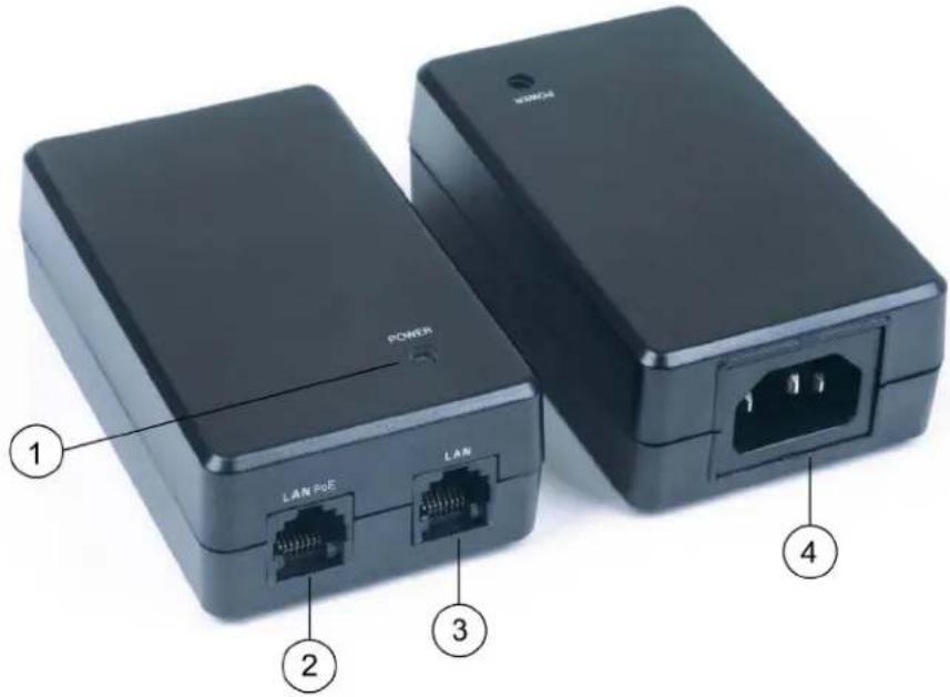
PWE-4803RU Physical View (Front and Back)
text_image
POWER LAN PGE LAN 1 2 3 4Connectors & Indicators
| # | CONNECTORS & INDICATORS | DESCRIPTION |
| 1 | POWER LED | (1) Tri-Color LED that illuminates to indicate the connection status of the LAN PoE port:Green indicates that a PoE device is connected and is accepting power;Flashing red indicates that a non-PoE device is connected;Amber indicates that no device is connected. |
| 2 | LAN PoELAN PoE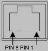 | (1) 8-wire RJ-45 connector;10Base-T/100Base-TXPower over Ethernet (PoE) port;Connects to 802.3af-compliant powered device.Maximum PoE load: 15.4 W(350 mA) @ 48 VDC nominal.*For information about pin assignments, refer to the illustration on the following page. |
(Continued on following page)
Connectors & Indicators (Continued)
| # | CONNECTORS & INDICATORS | DESCRIPTION |
| 3 | LANLAN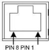 | (1) 8-wire RJ-45 connector;10Base-T/100Base-TXEthernet port;Connects to Ethernet LAN.For information about pin assignments, refer to the illustration below. |
| 4 | 100 – 250 VAC,50/60 Hz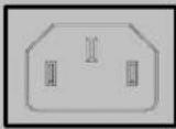 | (1) IEC 320 C14 socket with ground, mates with removable power cord (included). |
* Due to the inherent voltage drop over copper wire, a maximum of 12.9 W is guaranteed to be received by the PoE powered device over a cable run length of 328 feet (100 meters).
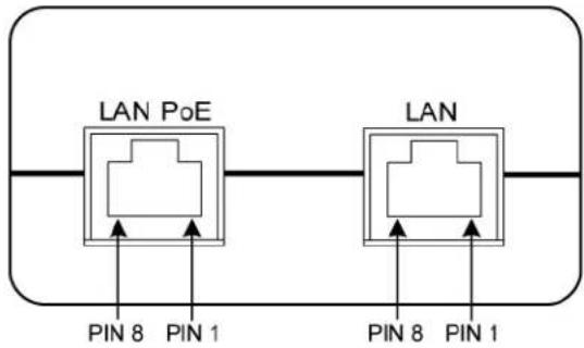
LAN PoE and LAN Connector Pin Assignments
text_image
LAN PoE PIN 8 PIN 1 LAN PIN 8 PIN 1LAN PoE Pins
- Data Pair 1 ←→ 1. Data Pair 1
- Data Pair 1 ←→ 2. Data Pair 1
- Data Pair 2 3. Data Pair 2
- +VDC 4. No Connection
- +VDC 5. No Connection
- Data Pair 2 ←→ 6. Data Pair 2
7.-VDC 7. No Connection - -VDC 8. No Connection
NOTE: In the listing of LAN PoE and LAN connector pins assignments above, arrows denote internal pin connections.
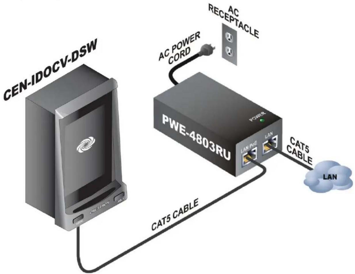
Setup
Complete the following steps to properly set up and connect the PoE injector. Refer to the illustration at the conclusion of the procedure.
- Attach the supplied AC power cord to the IEC 320 connector on the PoE injector.
- Insert the other end of the power cord into an active AC receptacle.
- Using a CAT5 cable, connect the LAN port of the PoE injector to the LAN.
- Using a CAT5 cable, connect the LAN PoE port of the PoE injector to the PoE port of an 802.3af-compliant powered device.
PoE Injector Hookup
flowchart
graph TD
    A["CEN-IDOCV-DSW"] -->|AC POWER CORD| B["PWE-4803RU"]
    B -->|CAT5 CABLE| A
    B -->|AC RECEPTACLE| C["RECEPTACLE"]
    B -->|LAN PoE| D["LAN"]
    B -->|LAN| E["LAN"]
    B -->|CAT5 CABLE| F["LAN"]
Return and Warranty Policies
Merchandise Returns / Repair Service
- No merchandise may be returned for credit, exchange or service without prior authorization from CRESTRON. To obtain warranty service for CRESTRON products, contact an authorized CRESTRON dealer. Only authorized CRESTRON dealers may contact the factory and request an RMA (Return Merchandise Authorization) number. Enclose a note specifying the nature of the problem, name and phone number of contact person, RMA number and return address.
- Products may be returned for credit, exchange or service with a CRESTRON Return Merchandise Authorization (RMA) number. Authorized returns must be shipped freight prepaid to CRESTRON, 6 Volvo Drive, Rockleigh, N.J. or its authorized subsidiaries, with RMA number clearly marked on the outside of all cartons. Shipments arriving freight collect or without an RMA number shall be subject to refusal. CRESTRON reserves the right in its sole and absolute discretion to charge a 15% restocking fee plus shipping costs on any products returned with an RMA.
- Return freight charges following repair of items under warranty shall be paid by CRESTRON, shipping by standard ground carrier. In the event repairs are found to be non-warranty, return freight costs shall be paid by the purchaser.
CRESTRON Limited Warranty
CRESTRON ELECTRONICS, Inc. warrants its products to be free from manufacturing defects in materials and workmanship under normal use for a period of three (3) years from the date of purchase from CRESTRON, with the following exceptions: disk drives and any other moving or rotating mechanical parts, pan/tilt heads and power supplies are covered for a period of one (1) year; touchscreen display and overlay components are covered for 90 days; batteries and incandescent lamps are not covered.
This warranty extends to products purchased directly from CRESTRON or an authorized CRESTRON dealer. Purchasers should inquire of the dealer regarding the nature and extent of the dealer's warranty, if any.
CRESTRON shall not be liable to honor the terms of this warranty if the product has been used in any application other than that for which it was intended or if it has been subjected to misuse, accidental damage, modification or improper installation procedures. Furthermore, this warranty does not cover any product that has had the serial number altered, defaced or removed.
This warranty shall be the sole and exclusive remedy to the original purchaser. In no event shall CRESTRON be liable for incidental or consequential damages of any kind (property or economic damages inclusive) arising from the sale or use of this equipment. CRESTRON is not liable for any claim made by a third party or made by the purchaser for a third party.
CRESTRON shall, at its option, repair or replace any product found defective, without charge for parts or labor. Repaired or replaced equipment and parts supplied under this warranty shall be covered only by the unexpired portion of the warranty.
Except as expressly set forth in this warranty, CRESTRON makes no other warranties, expressed or implied, nor authorizes any other party to offer any warranty, including any implied warranties of merchantability or fitness for a particular purpose. Any implied warranties that may be imposed by law are limited to the terms of this limited warranty. This warranty statement supersedes all previous warranties.
Trademark Information
All brand names, product names and trademarks are the sole property of their respective owners. Windows is a registered trademark of Microsoft Corporation. Windows95/98/Me/XP/Vista and WindowsNT/2000 are trademarks of Microsoft Corporation. iPod, iTunes and Mac OS are trademarks of Apple Computer, Inc., registered in the U.S. and other countries. PowerPC is a trademark of International Business Machines Corporation.
This page is intentionally left blank.

CRESTRON®
Crestron Electronics, Inc. Operations & Installation Guide - DOC. 6827A
15 Volvo Drive Rockleigh, NJ 07647 (2025067)
Tel: 888.CRESTRON 08.09
Fax: 201.767.7576 Specifications subject to
www.crestron.com change without notice.