
C5 Dag (2009) - Automotive CITROEN - Free user manual and instructions
Find the device manual for free C5 Dag (2009) CITROEN in PDF.


| Product Type | Automobile |
| Brand | Citroën |
| Model | C5 Dag |
| Year | 2009 |
| Category | Automotive |
| Engine Options | Petrol: 1.8L 16V (127 hp), 2.0L Bioflex (143 hp), 1.6L THP (159 hp), 3.0L V6 (215 hp) |
| Transmission | Manual (5/6-speed) or Automatic (6-speed) |
| Fuel Tank Capacity | 71 litres |
| Length | 4779 mm (saloon) |
| Width | 1853 mm |
| Height | 1456 mm |
| Kerb Weight | 1546 - 1836 kg (depending on engine/body) |
| Gross Vehicle Weight (GVW) | 2015 - 2366 kg |
| Max Power | Up to 155 kW (215 hp) at 6000 rpm |
| Max Torque | Up to 290 Nm at 3750 rpm |
| Drive Type | Front-wheel drive |
| Seating Capacity | 5 |
| Safety Systems | ABS, ESP/ASR, front/side/curtain airbags, seat belt reminders |
| Comfort Features | Electric parking brake, dual-zone automatic climate control, programmable heating, electrochromic mirrors, heated seats, massage driver seat |
| Dashboard Display | Instrument panel with trip computer, service indicator, oil level, temperature gauges |
| Multimedia | Monochrome or 16:9 colour screen, audio system, Bluetooth, navigation (MyWay/NaviDrive optional) |
| Steering Wheel Adjustment | Height and reach adjustable |
| Exterior Mirrors | Electric adjustment, folding, auto-dimming driver side, heated with rear screen |
| Rear View Mirror | Manual or auto-dimming day/night |
| Documentation | 306-page user manual available as free PDF download |
Frequently Asked Questions - C5 Dag (2009) CITROEN
User questions about C5 Dag (2009) CITROEN
0 question about this device. Answer the ones you know or ask your own.
Ask a new question about this device
Download the instructions for your Automotive in PDF format for free! Find your manual C5 Dag (2009) - CITROEN and take your electronic device back in hand. On this page are published all the documents necessary for the use of your device. C5 Dag (2009) by CITROEN.
USER MANUAL C5 Dag (2009) CITROEN
natural_image
Close-up of a car's interior control panel with labeled buttons (A and B), no readable text or symbols beyond labelsDoor mirrors
Each fitted with an adjustable mirror glasses providing the lateral rearward vision necessary for overtaking or parking. They can also be folded.
Adjustment
With the ignition on:
move control A to the right or to the left to select the corresponding mirror,
move control B in all four directions to adjust,
return control A to the central position.
The objects observed are, in reality, closer than they appear.
Take this into account in order to correctly judge the distance of vehicles approaching from behind.
Demisting/defrosting of the door mirrors is associated with that of the rear screen.
Folding
from outside; lock the vehicle using the remote control or the key.
from inside; with the ignition on, pull control A rearwards.
If the mirrors are folded using control A, they will not unfold when the vehicle is unlocked. Control A must be pulled again.
Unfolding
from outside; unlock the vehicle using the remote control or the key.
from inside; with the ignition on, pull control A rearwards.
If the position is changed manually, a long press on control A re-engages the mirror.
The folding and unfolding of the exterior mirrors using the remote control can be deactivated by a CITROËN dealer.
Rear view mirror
Adjustable mirror providing a central rearward view.
Equipped with an anti-dazzle system, useful in poor light.
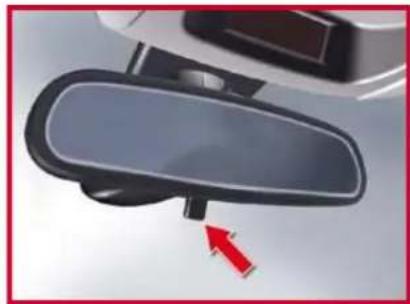
Manual day/night model
natural_image
Close-up of a car rearview mirror with a red arrow pointing to the lens (no text or symbols visible)Adjustment
Adjust the mirror so that the glass is directed correctly in the "day" position.
Day/night position
Pull the lever to change to the "night" anti-dazzle position.
Push the lever to change to the normal "day" position.
As a safety precaution, the mirrors must be adjusted to reduce the "blind spot".
COMFORT
Automatic day/night model
natural_image
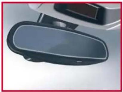
Close-up of a black and white electronic device with a glossy surface (no visible text or symbols)By means of a sensor, which measures the light from the rear of the vehicle, this system automatically and progressively changes between the day and night uses.
It has an anti-dazzle system which darkens the mirror glass: this reduces any driver discomfort caused by the light beam of following vehicles, the sun...
In order to guarantee optimum visibility during your manoeuvres, the mirror lightens automatically when reverse gear is engaged.
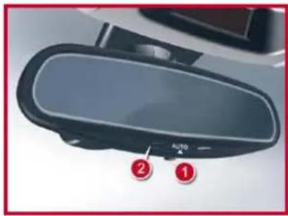
In vehicles fitted with electrochrome exterior rear view mirrors, the system has an on/off button and an associated warning lamp.
on
With the ignition on, press on button 1.
The warning lamp 2 comes on and the mirror is in automatic mode.
Off
Press on button 1.
The warning lamp 2 goes out and the mirror remains in its lightest definition.
STEERING WHEEL ADJUSTMENT
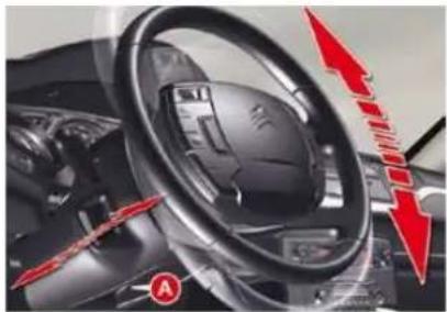
The steering wheel can be adjusted for height and reach to adapt the driving position to the size of the driver.
natural_image
Interior view of a car dashboard with steering wheel and red directional arrows indicating motion (no text or symbols)Adjustment
First, adjust the driver's seat to the most suitable position.
When stationary, pull the lever A to unlock the steering wheel adjustment.
Adjust for height and reach.
Push the lever to lock the steering wheel adjustment.
After locking, if you press firmly on the steering wheel, a slight click may be heard.
As a safety precaution, these operations must only be carried out while the vehicle is stationary.
MONITORING
|
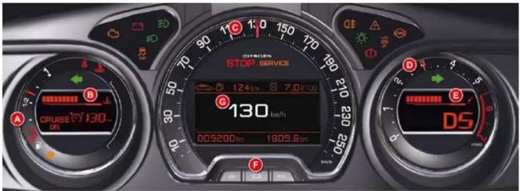
INSTRUMENT PANELS - PETROL AND DIESEL - MANUAL AND AUTOMATIC GEARBO)
Panel grouping together the dials and vehicle operation indicator and warning lamps.
A. Fuel gauge
B. Indicator:
• Coolant temperature
- Cruise control/Speed limiter information
C. Speedometer
D. Rev counter
E. Indicator:
• Engine oil temperature
●Gear selector position and gear engaged (Automatic gearbox)
F. Controls:
- Lighting rheostat
- Resetting to zero of trip mileage computer and maintenance indicator
G. Instrument panel screen indicating:
- Depending on the page selected with the left-hand control knob on the steering wheel:
- Digital speed repeater
- Trip computer
- Navigation (guidance) information
- Display of message alerts
- Engine oil level check
- Service indicator
- Permanently:
- Trip mileage recorder
- Total mileage recorder
MONITORING
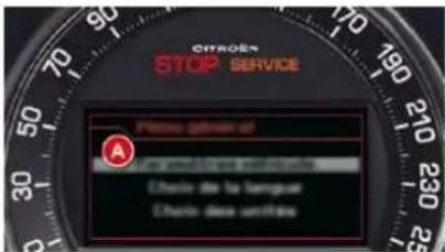
Main menu
The instrument screen A is located in the centre of the instrument panel.
- With the vehicle stationary, you can access the main menu of the screen by quickly pressing on the left-hand thumb wheel B on the steering wheel.
- Whilst driving, the message "Action impossible whilst driving" is displayed on the instrument panel if you try to open the main menu.
The main menu allows you to programme certain vehicle and instrument panel screen functions:
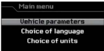
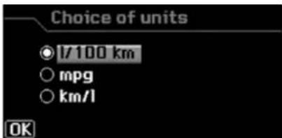
"Choice of units" menu
This allows you to choose metric or imperial units.
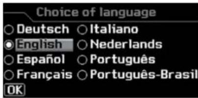
"Choice of language" menu
This allows you to choose the display and voice recognition language.
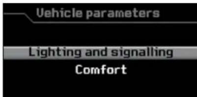
"Vehicle parameters" menu
This allows you to access the parameters relating to:
- The vehicle lighting.
- The comfort levels in the vehicle.
MONITORING
|
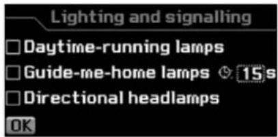
"Lighting" menu
Once you have selected this menu, you can:
- Activate/deactivate the lighting of the daytime running lamps *.
Activate/deactivate the guide-me-home lighting and adjust its duration.
Activate/deactivate the dual-function Xenon directional head-lamps.
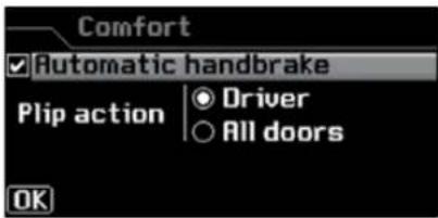
"Comfort" menu
Once you have selected this menu, you can:
- Activate/deactivate the driver's welcome lighting function.
Select unlocking of all the doors or just the driver's door.
Activate/deactivate automatic operation of the electric parking brake.
MONITORING
TRIP COMPUTER
System which provides current information concerning your journey (range, consumption, etc.)
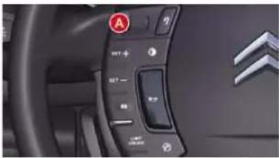
Information displays
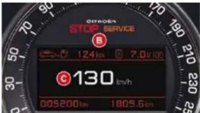
the instrument panel screen.
Turn the left-hand thumb wheel A on the steering wheel to display the various trip computer tabs in succession:
- the current information tab is displayed in zone B of the instrument panel, with:
- the range,
• the current fuel consumption,
- the trip "1" tab is displayed in zone C of the instrument panel, with:
• the distance travelled,
• the average fuel consumption,
• the average speed,
for the fi rst trip.
- the trip "2" tab is displayed in zone C of the instrument panel, with:
• the distance travelled,
• the average fuel consumption,
• the average speed,
for the second trip.
Trip zero reset The trip computer
is displ
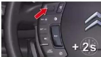
When the trip required is displayed, press the left-hand thumb wheel on the steering wheel for more than two seconds.
Trips "1" and "2" are independent but their use is identical.
For example, trip "1" can be used for daily fi gures and trip "2" for monthly fi gures.
MONITORING
I
A few definitions...
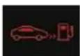
Range
(miles or km)
This indicates the distance which can still be travelled with the fuel remaining in the tank in relation to the average fuel consumption over the last few miles (kilometres) travelled.
This value may vary following a change in the style of driving or the relief, resulting in a significant change in the current fuel consumption.
When the range falls below 20 miles (30 km), dashes are displayed. After filling with at least 5 litres of fuel, the range is recalculated and is displayed when it exceeds 60 miles (100 km).
If dashes are displayed continuously while driving in place of the digits, contact a CITROËN dealer.

Current fuel consumption (mpg or l/100 km or km/l)
This is the average fuel consumption during the last few seconds.
This function is only displayed from 20 mph (30 km/h).
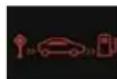
Average fuel consumption (mpg or l/100 km or km/l)
This is the average fuel consumption since the last trip computer zero reset.

Distance travelled (miles or km)
This indicates the distance travelled since the last trip computer zero reset.
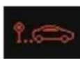
Average speed (mph or km/h)
This is the average speed calculated since the last trip computer zero reset (ignition on).
MONITORING
Return to the main instrument panel screen display
Successive rotations of the left-hand thumb wheel on the steering wheel allow you to return to the main instrument panel screen display (vehicle speed), via the navigation information screen, then the screen displaying only the total mileage and the trip mileage (bottom of screen).
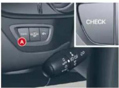
Log of alerts
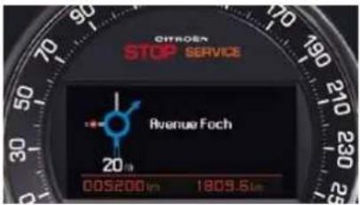
Display of navigation information on instrument panel screen
You can display navigation information on the instrument panel screen by rotating the left-hand thumb wheel on the steering wheel.
This function allows you to display the log of alerts.
Press on button A.
The following messages appear consecutively on the instrument panel screen:
- Tyre pressure check.
- Service indicator reminder.
- Display of message alerts.
- Oil level check.
MONITORING
Return to the main instrument panel screen display
Successive rotations of the left-hand thumb wheel on the steering wheel allow you to return to the main instrument panel screen display (vehicle speed), via the navigation information screen, then the screen displaying only the total mileage and the trip mileage (bottom of screen).
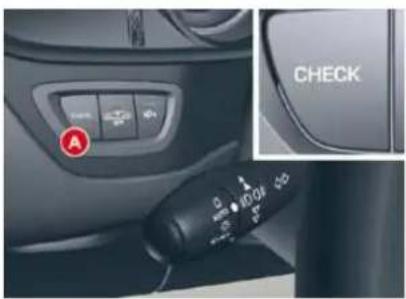
Log of alerts
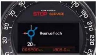
Display of navigation information on instrument panel screen
You can display navigation information on the instrument panel screen by rotating the left-hand thumb wheel on the steering wheel.
This function allows you to display the log of alerts.
Press on button A.
The following messages appear consecutively on the instrument panel screen:
- Tyre pressure check.
- Service indicator reminder.
- Display of message alerts.
- Oil level check.
MONITORING
|
Indicator and warning lamps
Visual indicators informing the driver that a system is in operation (operation or deactivation indicator lamps) or of the occurrence of a fault (warning lamp).
When the ignition is switched on
Certain warning lamps come on for a few seconds when the vehicle's ignition is switched on.
When the engine is started, these same warning lamps should switch off. If they remain on, before moving off, refer to the information on the warning lamp concerned.
! The warning lamps may come on continuously (fi xed) or fl ash.
Certain warning lamps may come on in two different modes. Only by relating the type of lighting to the operating status of the vehicle can it be ascertained whether the situation is normal or whether a fault has occurred.
Associated warnings
The switching on of certain warning lamps may be accompanied by an audible signal and a message on the multifunction screen.
Operation indicator lamps
If one of the following indicator lamps comes on, this confi rms that the corresponding system has come into operation.
| Warning lamp | is on | Cause | Action/Observations | |
 | Left-hand direction indicato r | fl ashing with buzzer. | The lighting stalk is pushed down. | |
 | Right-hand direction indicator | fl ashing with buzzer. | The lighting stalk is pushed up. | |
 | Sidelamps | fi xed. | The lighting stalk is in the "Sidelamps" position. | Turn the control to the desired position. |
 | Dipped beam headlamps | fi xed. | The lighting stalk is in the "Dipped beam headlamps" position. | Turn the control to the desired position. |
 | Main beam headlamps | fi xed. | The lighting stalk is pulled towards you. | Pull the stalk to return to dipped beam headlamps. |
MONITORING
| Warning lamp | is on | Cause | Action/Observations | |
| #D | Front foglamps | fi xed. | The front foglamps are switched on. | Turn the ring on the stalk rearwards twice to switch off the front foglamps. |
| O# | Rear foglamps | fi xed. | The rear foglamps are switched on. | Turn the ring on the stalk rearwards to switch off the rear foglamps. |
| oo | Diesel engine pre-heating | fi xed. | The ignition switch is at the 2nd position (ignition on). | Wait until the warning lamp has switched off before starting.The duration for which the warning lamp is on is determined by the climatic conditions. |
| (P) | Parking brake | fi xed. | The parking brake is applied or not properly released. | Release the parking brake to switch off the warning lamp, keeping your foot on the brake pedal.Observe the safety recommendations.For further information on the parking brake, refer to the "Driving" section. |
| fl ashing. | The parking brake is not fully applied or is released. | |||
| Passenger's airbag system | fi xed. | The control switch, located in the glove box, is in the "ON" position.The passenger's front airbag is activated.In this case, do not install a rear-facing child seat. | Turn the control switch to the "OFF" position to deactivate the front passenger's airbag.In this case you can install a rear-facing child seat.The passenger's airbag system is automatically put into service on starting the vehicle ("ON" position). | |
|
MONITORING
|
Deactivation indicator lamps
If one of the following indicator lamps comes on, this confirms that the corresponding system has been switched off intentionally. This is accompanied by an audible signal and a message on the multifunction screen.
| Warning lamp | is on | Cause | Action/Observations | |
 | Passenger's airbag system | fixed. | The control, located in the glove box, is set to the OFF position.The passenger's front airbag is deactivated.In this case you can install a "rear facing" child seat. | Set the control to the ON position to activate the passenger's front airbag. In this case, do not fi t a child seat in the rear-facing position.The passenger's airbag system is put into service automatically when the vehicle is started (ON position). |
| [YSWV] | ESP/ASR | fixed. | The button, located in the middle of the dashboard, is pressed. Its indicator lamp is on.The ESP/ASR is deactivated. ESP: electronic stability programme.ASR: anti-skid regulation. | Press the button to activate the ESP/ASR. Its indicator lamp switches off.The ESP/ASR system is activated automatically when the vehicle is started. If deactivated, the system is reactivated automatically from approximately 30 mph (50 km/h). |
MONITORING
Warning lamps
When the engine is running or the vehicle is being driven, the switching on of one of the following warning lamps indicates a fault which requires action on the part of the driver.
Any fault resulting in the switching on of a warning lamp must be investigated further by reading the associated message on the multifunction screen.
If you encounter any problems, do not hesitate to contact a CITROËN dealer.
| Warning lamp | is on | Cause | Action/Observations | |
| STOP | STOP | fi xed, associated with another warning lamp. | It is associated with a punctured tyre or the engine coolant temperature. | Stop as soon as it is safe to do so. Park, switch off the ignition and call a CITROËN dealer. |
| SERVICE | Service | temporarily. | A minor fault has occurred for which there is no specifi c warning lamp. | Identify the fault by reading the message shown on the screen, such as, for example: - the closing of the doors, boot, rear screen or bonnet, - the remote control battery, - the tyre pressures, - saturation of the particle emission fi lter (Diesel). For any other faults, contact a CITROËN dealer. |
| fi xed. | A major fault has occurred for which there is no specifi c warning lamp. | Identify the fault by reading the message shown on the screen and contact a CITROËN dealer. | ||
| ( ! )+ABS | Braking | fi xed. | The braking system fl uid level has dropped signifi cantly. | Top up with brake fl uid recommended by CITROËN. If the problem persists, have the system checked by a CITROËN dealer. |
| fi xed, associated with the ABS warning lamp. | The electronic brake force distribution (EBFD) system has a fault. | Have it checked by a CITROËN dealer. | ||
MONITORING
|
| Warning lamp | is on | Cause | Action/Observations | |
 | Anti-lock Braking System (ABS) | fi xed. | The anti-lock braking system has a fault. | The vehicle retains conventional braking.Drive carefully at reduced speed and contact a CITROËN dealer without delay. |
 | Electric parking brake | fl ashing. | The electric parking brake is not applied automatically. | You must stop immediately where it is safe to do so.Park on level ground, switch off the ignition and contact a CITROËN dealer. |
 | Electric parking brake fault | fi xed. | The electric parking brake is faulty. | Contact a CITROËN dealer without delay.The parking brake can be released manually.For further information about the electric parking brake, refer to the "Driving" section. |
 | Deactivation of the automatic functions of the electric parking brake | fi xed. | The "automatic application" (on switching off the engine) and "automatic release" functions are deactivated or faulty. | Activate the function (according to country) via the vehicle confi guration menu or contact a CITROËN dealer. |
MONITORING
| Warning lamp | is on | Cause | Action/Observations | |
| Dynamic stability control (ESP/ASR) | fl ashing. The ESP/ASR regulation is active. | The system optimises traction and improves the directional stability of the vehicle. | ||
| fi xed, accompanied by an audible signal and a message on the instrument panel screen. | Unless it has been deactivated with the indicator lamp on the button on, the ESP/ASR system is faulty. | Have it checked by a CITROËN dealer. | ||
| Engine autodiagnosis system | fi xed. | The emission control system has a fault. | This lamp should switch off when the engine is started.If it does not switch off, contact a CITROËN dealer urgently. | |
| fl ashing. | The engine management system has a fault. | Risk of destruction of the catalytic convertor.Have it checked by a CITROËN dealer | ||
|
MONITORING
|
| Warning lamp | is on | Cause | Action/Observations | |
 | Low fuel level | fi xed. | When it fi rst comes on there remains approximately 5 litres of fuel in the tank. | You must refuel as soon as possible to avoid running out of fuel.This warning lamp wil come on every time the ignition is switched on, until a suffi cient addition of fuel is made.Fuel tank capacity: 71 litres.Never continue to drive until you run out of fuel, this could damage the emission control and injection systems. |
 | Maximum coolant temperature | fi xed red. | The temperature of the cooling system is too high. | Stop as soon as it is safe to do so.Wait until the engine has cooled down before topping up the level, if necessary.If the problem persists, contact a CITROËN dealer. |
 | Battery charge | fi xed. | The battery charging circuit has a fault (dirty or loose terminals, slack or cut alternator belt, ...). | This lamp should switch off when the engine is started.If it does not switch off, contact a CITROËN dealer. |
 + + | Seat belt not fastened/unfastened | fi xed. | The driver and/or the front/rear passenger has not fastened or has unfastened their seat belt. | Pull the strap then insert the tongue in the buckle. |
| Seat belts not fastened/unfastened | fi xed, associated with the seat belt not fastened/unfastened warning lampl. | The illuminated dots represent the not fastened/unfastened passengers.They come on:- fi xed for 30 about seconds on starting the vehicle,- fi xed from 0 to 12 mph (0 to 20 km/h) when driving,- fl ashing above 12 mph (20 km/h), accompanie by an audible signal for about 120 seconds. | ||
MONITORING
Service indicator
System which informs the driver when the next service is due, in accordance with the manufacturer's servicing schedule.
The point at which the service is due is calculated from the last indicator zero reset. It is determined by two parameters:
- the distance travelled,
- the time elapsed since the last service.
More than 620 miles (1 000 km) remain before the next service is due
For 5 seconds after the ignition is switched on, the spanner symbolising the service operations comes on. The distance recorder display line indicates the distance remaining before the next service is due.
Example: 1 900 miles/km remain before the next service is due.
For 5 seconds after the ignition is switched on, the display indicates:
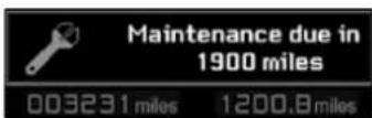
5 seconds after the ignition is switched on, the spanner is switched off; the distance recorder resumes its normal operation. The display then indicates the total and trip distances.
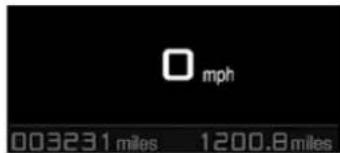
Less than 620 miles (1 000 km) remain before the next service is due
Examples: 500 miles (900 km) remain before the next service is due.
For 5 seconds after the ignition is switched on, the display indicates:
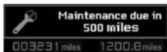
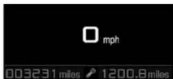
5 seconds after the ignition is switched on, the distance recorder resumes its normal operation. The spanner remains on to indicate that a service must be carried out soon.
Service overdue
For 5 seconds after the ignition switched on, the spanner flashes to indicate that the service must be carried out as soon as possible.
Example: the service is overdue by 300 miles/km.
For 5 seconds after the ignition is switched on, the display indicates:
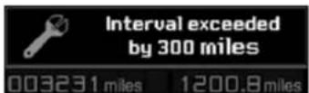
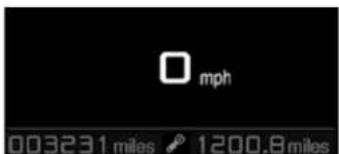
5 seconds after the ignition is switched on, the distance recorder resumes its normal operation. The spanner remains lit.
The distance remaining may be weighted by the time factor, depending on the driver's driving habits.
Therefore, the spanner may also come on if you have exceeded the two year service interval.
MONITORING
1
Service indicator zero reset
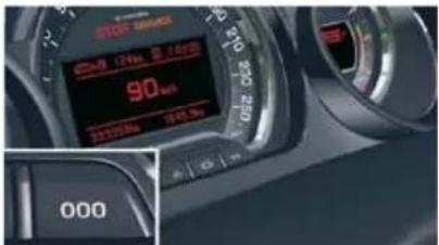
After each service, the service indicator must be reset to zero.
The procedure for resetting to zero is as follows:
switch off the ignition,
press and hold the trip distance recorder zero reset button,
switch on the ignition; the distance recorder display begins a countdown,
when the display indicates "=0", release the button; the spanner disappears.
Following this operation, if you wish to disconnect the battery, lock the vehicle and wait at least five minutes for the zero reset to be taken into account.
Engine oil level indicator Oil level gauge fault
System which informs the driver whether the engine oil level is correct or not.
This information is indicated for a few seconds when the ignition is switched on, after the service information.
The level read will only be correct if the vehicle is on level ground and the engine has been off for more than 15 minutes.
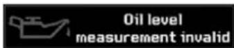
This is indicated by displaying of the message "Oil level measurement invalid". Consult a CITROËN dealer.
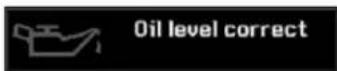
Oil level correct
Oil level low
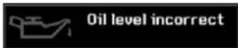
This is indicated by displaying of the message "Oil level incorrect".
If the low oil level is confirmed by a check using the dipstick, it is essential that the level is topped up to prevent damage to the engine.
MONITORING
1
Service indicator zero reset
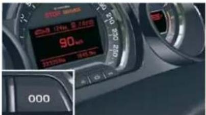
After each service, the service indicator must be reset to zero.
The procedure for resetting to zero is as follows:
switch off the ignition,
press and hold the trip distance recorder zero reset button,
switch on the ignition; the distance recorder display begins a countdown,
when the display indicates "=0", release the button; the spanner disappears.
Following this operation, if you wish to disconnect the battery, lock the vehicle and wait at least five minutes for the zero reset to be taken into account.
Engine oil level indicator Oil level gauge fault
System which informs the driver whether the engine oil level is correct or not.
This information is indicated for a few seconds when the ignition is switched on, after the service information.
The level read will only be correct if the vehicle is on level ground and the engine has been off for more than 15 minutes.
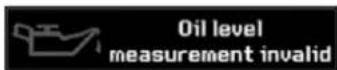
This is indicated by displaying of the message "Oil level measurement invalid". Consult a CITROËN dealer.
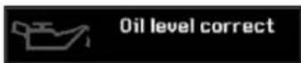
Oil level correct
Oil level low
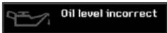
This is indicated by displaying of the message "Oil level incorrect".
If the low oil level is confirmed by a check using the dipstick, it is essential that the level is topped up to prevent damage to the engine.
MONITORING
Engine oil temperature gauge
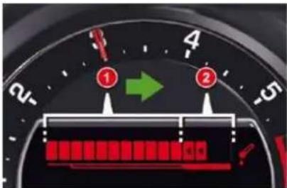
Under normal operating conditions, the bars should be within section 1. In severe operating conditions, the bars may extend into section 2.
In this event, slow down, and if necessary, stop the engine and check the levels (see corresponding chapter).
Coolant temperature indicator
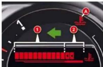
Under normal operating conditions, the bars should be within section 1. In severe operating conditions, the bars may extend into section 2, the engine coolant temperature warning lamp A and the STOP warning lamp will light up, stop immediately. Switch off the ignition. The cooling fan may continue to operate for a certain time.
Consult a CITROËN dealer.
If the SERVICE warning lamp lights up, check the levels (see corresponding chapter).
Fuel gauge indicator
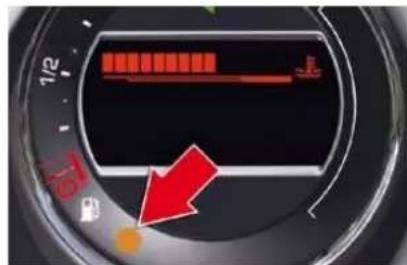
On horizontal ground, the lighting of the fuel low warning lamp warns you that you are at the reserve level.
A message alert is displayed on the instrument panel.
MONITORING
|
Total distance recorder
System which measures the total distance travelled by the vehicle during its life.
The total and trip distances are displayed for thirty seconds when the ignition is switched off, when the driver's door is opened and when the vehicle is locked or unlocked.
Trip distance recorder
System which measures a distance travelled during a day or other period since it was reset to zero by the driver.
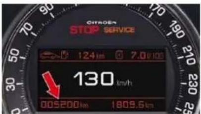
With the ignition on, press the button until zeros appear.
Lighting rheostat
System for manual adjustment of the brightness of the instruments and controls in relation to the exterior brightness.
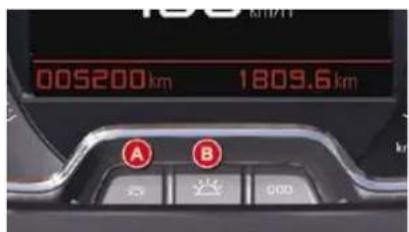
Operation
Press button A to decrease the brightness of the instruments and controls.
Press button B to increase the brightness of the instruments and controls.
Deactivation
When the lights are off, or in day mode on vehicles fitted with daytime running lights, pressing the buttons does not have any effect.
MULTIFUNCTION SCREENS
MONOCHROME SCREEN C
Presentation
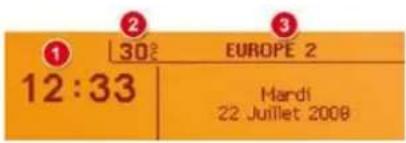
1. Time
-
Ambient temperature
-
Date and display zone
When the outside temperature is between +3 °C and -3 °C, the temperature display fl ashes (ice risk).
The ambient temperature displayed may be greater than the actual temperature, if the vehicle is parked in bright sunlight.
Controls
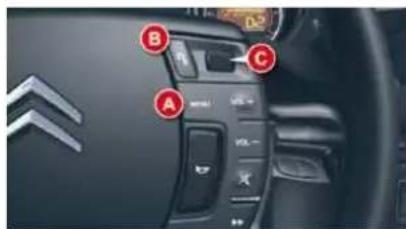
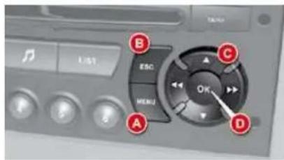
A. Access to the "Main Menu"
B. Cancellation of the operation or return to the previous display
C. Scrolling in the screen menus Confirmation at the steering wheel
D. Confirmation on the audio equipment control panel
It is recommended that the driver should not operate the controls while the vehicle is in motion.
Main Menu
Press on the button A to view the Main Menu of the multifunction screen. This menu gives you access to the following functions:
11

Personalisation - Configuration
This permits activation/deactivation of the:
- brightness and contrast of the multifunction screen,
- date and time,
- units of the outside temperature displayed.

Radio-CD
(see "Audio and Telematics" chapter)

Bluetooth® system
(see "Audio and Telematics" chapter)
MULTIFUNCTION SCREENS
Adjusting the brightness and contrast
Press on A.
Use C to select the "Brightness - video adjustment" menu. Confi rm with a press on C on the steering wheel or D on the audio equipment.
Select the configuration of the screen using C. Confirm with a press on C on the steering wheel or D on the audio equipment.
Select the brightness setting. Confi rm with a press on C on the steering wheel or D on the audio equipment.
Select the inverse or normal display mode using C then validate with a press on C on the steering wheel or D on the audio equipment. To adjust the brightness select "+" or "-" and save your setting with a press on C.
Confirm with "OK" on the screen.
Adjusting the date and the time
Press on A.
Use C to select the "Date and time adjustment" menu, then confirm your choice with a press on C on the steering wheel or D on the audio equipment.
Select the screen configuration using C. Confi rm with a press on C on the steering wheel or D on the audio equipment.
Select the date and the time settings, using B. Confirm with a press on C on the steering wheel or D on the audio equipment.
Press C to select the values you wish to modify. Confirm your choice with a press on C on the steering wheel or D on the audio equipment.
Confirm with "OK" on the screen.
Choosing the units
Press on A.
Use C to select the "Choice of units" menu, then confirm your choice with a press on C on the steering wheel or D on the audio equipment.
Using C, select the unit then validate with a press on C on the steering wheel or D on the audio equipment.
Confirm with "OK" on the screen.
Selection of the type of information displayed (Mode)
Successive presses on the end of the wiper stalk or on the MODE button on the audio equipment permit selection of the type of information presented on the multifunction screen (date or radio, CD, MP3 CD, CD changer).
MULTIFUNCTION SCREENS
16/9 COLOUR SCREEN (WITH MY WAY)
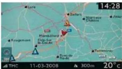
Controls
natural_image
Front view of a car dashboard with control panels and buttons (no visible text or symbols)"SETUP" menu
11
Displays on the screen
It displays the following information automatically and directly:
- time,
- date,
- altitude,
- ambient temperature (the value displayed fl ashes if there is a risk of ice),
- audio functions,
- satellite navigation system information.
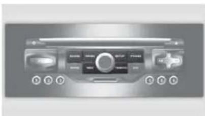
From the MyWay control panel, to select one of the applications:
press the dedicated "RADIO", "MUSIC", "NAV", "TRAFFIC", "SETUP" or "PHONE" button for access to the corresponding menu,
turn the dial to move the selection,
press the dial to confirm the selection,
or
press the "ESC" button to abandon the current operation and return to the previous display.
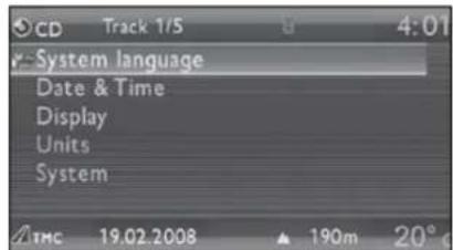
Press the "SETUP" button to gain access to the "SETUP" menu. This allows you to select from the following functions:
- "System language",
- "Date & time",
- "Display",
- "Units",
- "System".
System language
This menu allows you to select the language used by the display: Deutsch, English, Espanol, Français, Italiano, Nederlands, Polski, Portugues, Türkçe *.
For more information on these applications, refer to the "Audio Equipment" section or to the specific user guide given to you with the other owner's documents.
MULTIFUNCTION SCREENS
Date & time
This menu allows you to set the date and time, the format of the date and the format of the time.
To set the date and time:
Press the "SETUP" control.
Turn the dial to select "DATE & TIME".
Press the dial to confi rm.
Turn the dial to select "SET DATE & TIME".
Press the dial to confirm.
Turn the dial to select a fi eld:
- C for the day,
- D for the month,
- E for the year,
- F for the time.
Press the dial to confirm.
Turn the dial or use the alphanumeric keypad to select the digits which form the date and time.
Press the dial to confirm each field.
Turn the dial to select "DATE FORMAT".
Choose the format required and press the dial to confirm.
Turn the dial to select "TIME FORMAT".
Choose the format required and press the dial to confirm.
Units
This menu allows you to select the units for temperature (°C or °F) and distance (miles or kilometres).
System
This menu allows you to restore the factory configuration, display the software version and activate scrolling text.
For safety reasons, configuration of the multifunction screen by the driver must be only done when stationary.
Display
This menu allows you to set the brightness of the screen, the screen colour scheme and the colour of the map (day/night or auto mode).
MULTIFUNCTION SCREENS
16/9 HIGH DEFINITION COLOUR SCREEN (WITH NAVIDRIVE 3D)
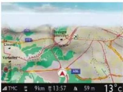
Displays on the screen
It displays the following information automatically and directly:
- time,
- date,
- altitude,
- ambient temperature (the value displayed fl ashes if there is a risk of ice),
- audio functions,
- telephone and address book information,
- satellite navigation system information.
Controls
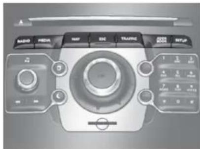
From the NaviDrive 3D control panel, to select one of the applications:
press the dedicated "RADIO", "MEDIA", "NAV", "TRAFFIC", "ADDR BOOK" or "SETUP" button for access to the corresponding menu,
turn the dial to move the selection,
^F press the dial to confirm the selection,
or
press the "ESC" button to abandon the current operation and return to the previous display.
For more information on these applications, refer to the "Audio Equipment" section or to the specific user guide given to you with the other owner's documents.
MULTIFUNCTION SCREENS
"SETUP" menu
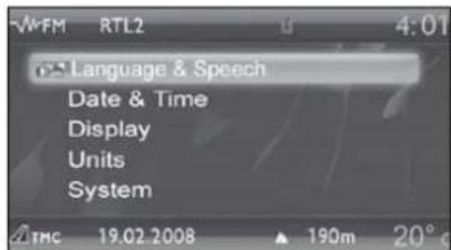
Press the "SETUP" button to gain access to the "SETUP" menu. This allows you to select from the following functions:
- "Languages and Speech",
- "Date & Time",
- "Display",
- "Units",
- "System".
Language & Speech
This menu allows you to:
- select the language used by the display (Deutsch, English, Espanol, Français, Italiano, Nederlands, Polski, Portugues, Türkçe *),
- select the voice recognition parameters (activation/deactivation, advice on use, personal voice programming, etc.),
- set the volume of the voice synthesiser.
Date & Time
This menu allows you to set the date and time, the format of the date and the format of the time (refer to the "Audio Equipment" section or to the specific user guide given to you with the other owner's documents).
Display
This menu allows you to set the brightness of the screen, the screen colour scheme and the colour of the map (day/night or auto mode).
Units
This menu allows you to select the units: temperature (°C or °F) and distance (km or miles).
System
This menu allows you to restore the factory configuration, display the software version and activate scrolling text.
For safety reasons, configuration of the multifunction screen by the driver must only be done when stationary.
* According to country.
COMFORT
natural_image
Interior view of a car cockpit with labeled sections A, B, C, D (no text or symbols beyond labels)VENTILATION
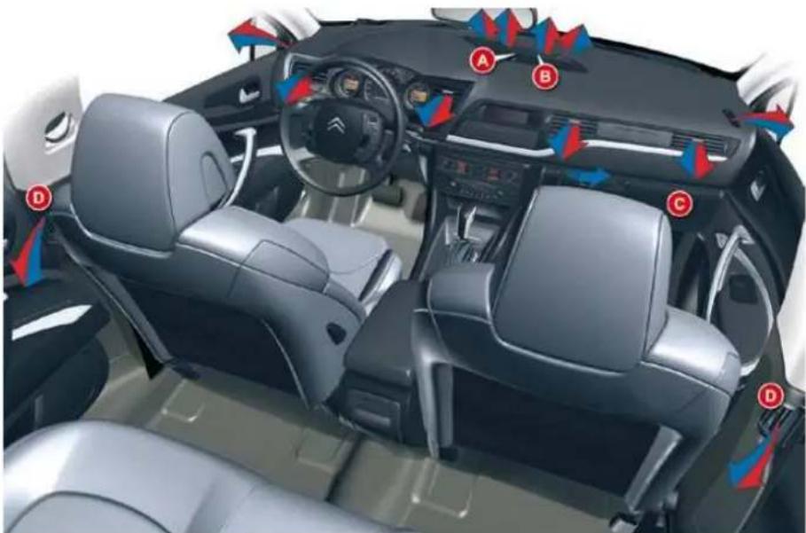
A. Sunshine sensor.
B. Soft air diffusion grille.
The soft air diffusion grille located in the centre of the dashboard provides optimum distribution of the air for the front seats.
This system eliminates unpleasant air currents while maintaining an optimum temperature in the passenger compartment.
To open the soft air diffusion grille, turn the wheel upwards.
To close the soft air diffusion grille, turn the wheel fully downwards.
In very hot weather, to obtain more satisfactory central and side ventilation, it is advisable to close the diffused air grille.
C. Cooled glove box.
D. Rear passenger vents.
COMFORT
HEATING, VENTILATION AND AIR CONDITIONING RECOMMENDATIONS
Air conditioning
We recommend use of the automatic regulation of the air conditioning.
It permits automatic and optimised control of all of the following functions: air flow, temperature in the passenger compartment and air distribution, by means of various sensors (ambient temperature, sunshine). This eliminates any need for you to change your settings other than the temperature value displayed.
Take care not to cover the sun-shine sensor A.
If you select the automatic mode (by pressing the "AUTO" control) and leave all of the vents open, optimum comfort will be maintained and humidity and condensation will be removed regardless of the exterior climatic conditions.
The temperature in the passenger compartment can only be lower than the ambient temperature if the air conditioning is on.
In order to be effective, the air conditioning must be used with the windows closed. If the vehicle has been parked in the sun for a long period and the interior temperature is very high, first ventilate the passenger compartment with the windows open for a few minutes, then close the windows.
To keep the air conditioning system in good working order it is essential that it is operated at least once a month.
The air conditioning uses engine power during its operation. As a result, the fuel consumption of the vehicle increases.
In certain cases of particularly arduous use (e.g. towing the maximum load on a steep gradient in high temperatures), switching off the air conditioning saves engine power and improves the towing capacity.
Air inlet
Check that the exterior grille for the air inlet, at the bottom of the wind-screen, is clean and free of dead leaves, snow, etc.
When washing the vehicle using a high pressure nozzle, avoid spraying at the air inlet.
Air circulation
Maximum comfort is obtained by means of a good distribution of air in the passenger compartment, both in the front and in the rear.
To obtain a uniform distribution of air, take care not to block the exterior air intake grille located at the base of the windscreen, the vents, the air outlets under the front seats and the air extractor located behind the flaps in the boot.
The front and rear vents are fitted with thumbwheels to adjust the air flow and direction. We recommend that you leave all of the vents open.
Dust filter/Odour filter (active carbon)
There is a filter for excluding odours and dust.
This filter must be changed in line with the vehicle's servicing schedule (see: "Maintenance and Warranty Guide").
COMFORT
DIGITAL AIR CONDITIONING (MONO-ZONE)

Mono-zone: this is the overall regulation of the temperature, distribution and flow of air in the passenger compartment.
The symbols and messages associated with the digital air conditioning controls appear on the multifunction screen.
- Automatic operation
- Temperature adjustment
- Air distribution adjustment
- Activation/deactivation of the air conditioning
- Air flow adjustment
- Front demisting - defrosting
- Rear demisting - defrosting
- Air recirculation - intake of exterior air
- Screen
1. Automatic operation
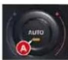
This is the normal system operating mode. In accordance with the level of comfort chosen, pressing this control, confirmed by the
switching on of indicator lamp A, permits automatic and simultaneous control of all of the following functions:
- Air flow.
- Temperature in the passenger compartment.
- Air distribution.
- Air intake.
- Air conditioning.
It is advisable to leave all of the vents open.
Simply pressing one of the controls, with the exception of control 2, switches the system to manual mode.
Indicator lamp A switches off.
2. Temperature adjustment
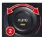
Turn control 2 to change the temperature:
- Clockwise to increase the temperature.
- Anticlockwise to reduce the temperature.
The setting required is displayed.
The value indicated on the display corresponds to a level of comfort and not to a temperature in degrees Celsius or Fahrenheit, depending on the screen confi guration.
A setting around the value 21 usually makes it possible to obtain optimum comfort. However, depending on your requirements, a setting between 18 and 24 is usual.
On entering the vehicle, the interior temperature may be much colder (or warmer) than is comfortable. There is no need to change the temperature displayed in order to obtain rapidly the level of comfort required.
The automatic regulation of the air conditioning will use its maximum performance settings to correct the temperature difference as quickly as possible.
COMFORT
Control via the manual controls
It is possible to adjust one or more functions manually, while leaving the other functions in automatic mode.
Press one of the controls, with the exception of that which regulates the temperature 2. Indicator lamp A switches off.
Switching to manual mode may result in discomfort (temperature, humidity, odour, condensation) and may not provide optimum comfort.
To return to automatic mode, press the "AUTO" control.
3. Air distribution adjustment
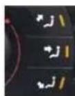
Press the controls 3 to change the distribution of the air flow.
The indicator lamps corresponding to the distribution chosen come on:
- Windscreen and front side windows.
- Front ventilation (central and side vents and air diffusion grille if open) and rear ventilation.
- Front and rear footwells.
Simultaneous display of the distribution of air to the windscreen and side windows and of front and rear ventilation is not possible.
4. Air conditioning
The air conditioning will only operate when the engine is running. The air blower control (air flow adjustment) must be active to obtain air conditioning.
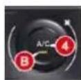
^2 Press control 4. Indicator light B comes on.
In order to be effective, the air conditioning must be used with the windows closed.
Deactivating the air conditioning may result in discomfort (temperature, humidity, odour, condensation).
5. Air flow adjustment
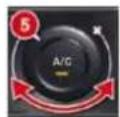
Turn control 5 to the right to increase the air flow or to the left to reduce it.
The air flow level is indicated by the progressive lighting of the blocks of the bar graph on the control panel display 9.
To prevent condensation and deterioration of the quality of the air in the passenger compartment, ensure that an adequate flow of air is maintained.
Switching off the ventilation
Turn control 5 to the left until the flow of air stops.
The "OFF" symbol is displayed on the multifunction screen.
This action switches off the display and the indicator lamps.
It deactivates all of the system's functions, with the exception of the rear screen demisting.
The temperature-related comfort is no longer controlled (temperature, humidity, odour, condensation).
Avoid driving for too long with the air conditioning off.
To reactivate the air conditioning:
Press control 1.
6. Front demisting - defrosting
In certain cases, the "AUTO" mode may not be suffi cient to demist or defrost the windows (humidity, several passengers, ice).
Press control 6 to clear the windows quickly. The indicator lamp comes on.
COMFORT
It controls the temperature, air flow and intake and distributes the ventilation to the windscreen and front side windows.
Resuming manual control exits from "Demisting" mode. It must be cancelled to permit renewal of the air in the passenger compartment and demisting.
Once the screen is clear, pressing control 1 returns the system to "AUTO" mode.
7. Rear demisting - defrosting
The heated rear screen operates independently of the air conditioning system.
Press control 7, with the engine running, to demist the rear screen and the door mirrors. The indicator lamp comes on.
Demisting is switched off automatically to prevent an excessive consumption of current and in relation to the ambient temperature.
It may be stopped by pressing control 7 again or when the engine is switched off.
However, demisting resumes when the engine is switched on again.
Switch off the rear screen and door mirrors demisting when you consider this necessary as low current consumption reduces fuel consumption.
8. Intake of exterior air/Recirculation of interior air
This function enables you to isolate the passenger compartment from exterior fumes and odours.
Press control 8 several times to set the air intake mode, the indicator lamp comes on.
It must be cancelled as soon as possible to permit renewal of the air in the passenger compartment and demisting.
- When starting with the engine cold, the flow will reach its optimum level gradually to prevent an excessive distribution of cold air.
- When entering the vehicle after it has been parked for a fairly long period, if the interior temperature is very different from your comfort setting there is no need to change the temperature displayed in order to quickly reach the level of comfort required. The system automatically uses its maximum performance to correct the difference in temperature as quickly as possible.
- The water resulting from the air conditioning condensation is discharged via an opening provided for this purpose; therefore, a puddle of water may form underneath the vehicle when stationary.
- In all seasons, if the weather is cool, the air conditioning is useful as it removes the humidity from the air and the condensation. Avoid driving for prolonged periods with the air conditioning switched off.
DIGITAL AIR CONDITIONING (DUAL-ZONE)
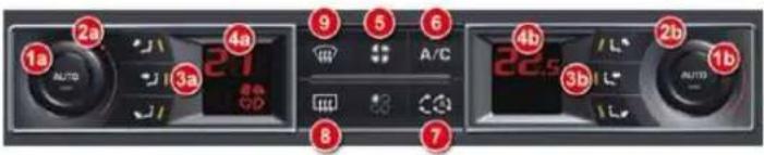
Dual-zone: this is the differentiated regulation of the temperature and air distribution on the driver's side and the front passenger's side.
The driver and front passenger can each adjust the temperature and the distribution of the air to suit their requirements.
The symbols and messages associated with the digital air conditioning controls appear on the multifunction screen.
1a. Automatic operation on the driver's side
1b. Automatic operation on the passenger's side
2a. Temperature adjustment on the driver's side
2b. Temperature adjustment on the passenger's side
3a. Air distribution adjustment on the driver's side
3b. Air distribution adjustment on the passenger's side
4a. Driver's zone screen
4b. Passenger's zone screen
5. Air flow adjustment
6. Activation/deactivation of the air conditioning
7. Air recirculation – intake of exterior air
8. Rear demisting - defrosting
9. Front demisting - defrosting
1a-1b. Automatic operation
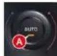
This is the normal system operating mode. In accordance with the level of comfort chosen, pressing this control, confirmed by the display
of indicator lamp A, permits automatic and simultaneous control of all of the following functions:
- Air flow.
- Temperature in the passenger compartment.
- Air distribution.
- Air conditioning.
- Automatic air recirculation.
It is advisable to leave all of the vents open. Simply pressing one of the controls, with the exception of temperature regulation 1a and
1b, switches the system to manual mode. Indicator lamp A switches off.
COMFORT
2a-2b. Temperature adjustment
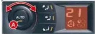
Turn control 2a to change the temperature on the driver's side and control 2b to change the temperature on the passenger's side: to the right to increase the temperature or to the left to reduce it.
The setting required is displayed. The value indicated on the display corresponds to a level of comfort and not to a temperature in degrees Celsius or Fahrenheit, depending on the screen configuration.
A setting around the value 21 usually makes it possible to obtain optimum comfort. However, depending on your requirements, a setting between 18 and 24 is usual.
On entering the vehicle, the interior temperature may be much colder (or warmer) than is comfortable. There is no need to change the temperature displayed in order to quickly obtain the level of comfort required.
The automatic regulation of the air conditioning will use its maximum performance settings to correct the temperature difference as quickly as possible.
Control via the manual controls
Press one of the controls, with the exception of temperature regulation 2a and 2b. The indicator lamps A on the "AUTO" controls switch off.
It is possible to adjust one or more functions manually while leaving the other functions in automatic mode.
Switching to manual mode may result in discomfort (temperature, humidity, odour, condensation) and may not provide optimum comfort.
To return to "AUTO" mode, press controls 1a and 1b. The indicator lamps A come on.
3a-3b. Air distribution adjustment
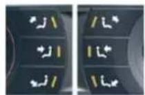
Press control 3a to change the distribution of the air flow on the driver's side.
Press control 3b to change the distribution of the air flow on the passenger's side.
The indicator lamps corresponding to the distribution chosen come on:
- Windscreen and front side windows.
- Front ventilation (central and side vents and air diffusion grille if open) and rear ventilation.
- Front and rear footwells.
Simultaneous display of the distribution of air to the windscreen and side windows and of front and rear ventilation is not possible.
COMFORT
5. Air flow adjustment
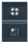
Press the control: - to increase the air flow, - to reduce the air flow.
The air flow level is indicated by the progressive lighting of the fan blade indicator lamps.
Reducing the flow to minimum switches the air conditioning OFF.
To prevent condensation and deterioration of the quality of the air in the passenger compartment, ensure that an adequate flow of air is maintained.
7. Air recirculation - intake of exterior air
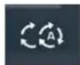
Automatic air intake mode It is activated by default in automatic comfort regulation.
Automatic mode is activated with reverse gear or operation of the screen-wash.
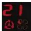
This function permits recirculation of the air and isolation the passenger compartment from exterior fumes and odours. It is inactive when the ambient temperature is below +5°C to avoid the risk of misting inside the vehicle.
Closing the air intake
Press control 7 to close the exterior air intake.
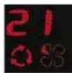
While retaining the other settings, this position allows the driver to isolate the passenger compartment at any time from unpleasant exterior odours and fumes.
It must be cancelled as soon as possible to permit renewal of the air in the passenger compartment and demisting.
6. Air conditioning

The air conditioning will only operate when the engine is running. The air blower control (air flow adjustment) must be active in order to obtain air conditioning.
Press control 6. The indicator lamp comes on.
In order to be effective, the air conditioning must be used with the windows closed.
Intake of exterior air
Press control 7 once to open the exterior air intake.
COMFORT
8. Rear demisting - defrosting
The heated rear screen operates independently of the air conditioning system.
Press control 8, with the engine running, to demist the rear screen and the mirrors. The indicator lamp comes on.
Demisting is switched off automatically to avoid excessive consumption of current and depending on the exterior temperature.
It may be stopped by pressing control 8 again or when the engine is switched off.
In this latter case, the demisting resumes if the engine is switched on again within one minute.
Switch off the rear screen and exterior mirrors demisting when you consider this necessary as low current consumption reduces fuel consumption.
9. Front demisting - defrosting
In certain cases, the "AUTO" mode may not be sufficient to demist or defrost the windows (humidity, several passengers, ice).
Press control 9 to clear the windows quickly. The indicator lamp comes on.
This system controls the temperature, air flow and intake and distributes the ventilation to the windscreen and front side windows.
Resuming manual control exits from the "Demisting" mode. It must be cancelled as soon as possible to permit renewal of the air in the passenger compartment and demisting.
Pressing one of the controls 1a and 1b returns the system to the "AUTO" mode.
When starting with the engine cold, air flow will reach its optimum level gradually to prevent an excessive distribution of cold air.
When entering the vehicle after it has been parked for a fairly long period, if the interior temperature is very different from your comfort setting there is no need to change the temperature displayed in order to quickly reach the level of comfort required. The system automatically uses its maximum performance to correct the difference in temperature as quickly as possible.
The water resulting from the air conditioning condensation is discharged via an opening provided for this purpose; therefore, a puddle of water may form underneath the vehicle when stationary.
In all seasons, if the weather is cool, the air conditioning is useful as it removes the humidity from the air and the condensation. Avoid driving for prolonged periods with the air conditioning switched off.
COMFORT
PROGRAMMABLE HEATING
The programmable heating operates independently of the engine.
When the engine is off, it pre-heats the coolant circuit in order to benefit from an optimum engine operating temperature from the time the engine is switched on.
The programmable heating system is switched on using the long range remote control. Activation can be immediate or deferred by means of a programming function.
If a malfunction of the programmable heating system occurs, contact a CITROËN dealer.
Programming remote control
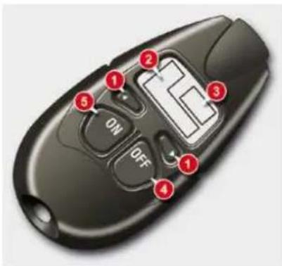
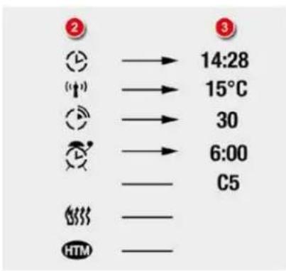
The heating system programming remote control consists of the following buttons and displays:
- Scrolling functions menu buttons.
- Function indicator lights: clock, temperature, operating time, programmed time, heater operation, heating management symbols.
- Digital displays: time, temperature, duration of operation, programmed time or level of heating.
- Off button.
- On button.
Displays on the remote control screen
Displaying the functions
natural_image
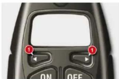
Close-up of a black handheld device with control buttons and a display screen (no readable text or symbols)Press the buttons 1 in succession to display the functions.
The first press of the left-hand or right-hand button displays the time.
Next, the left-hand button permits access to the programming time then to the level of heating (C1 to C5).
The right-hand button permits access to the passenger compartment temperature then to the duration of operation of the heater if it is to be switched on immediately.
The passenger compartment temperature information is only available when the engine is off.
COMFORT
Setting the time
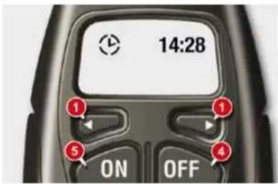
Once the time has been displayed, by means of the buttons 1, press buttons 4 and 5 simultaneously within 10 seconds.

This symbol fl ashes.
Set the time using the buttons 1. Press buttons 4 and 5 simultaneously to save it.

This symbol is displayed (fi xed).
Immediate activation
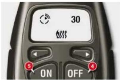
Press button 5 (ON) until the message "OK" appears.
When the signal has been received, the message "OK" is displayed along with the duration of operation.

The heater starts and this symbol is displayed.
To deactivate the function, press button 4 (OFF) until the message "OK" appears.

This symbol is switched off.
When carrying out these operations, if the message "FAIL" appears, the signal has not been received. Repeat the procedure after changing your location.
Setting the duration of operation
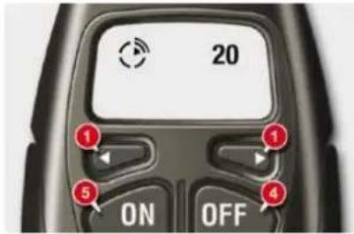
Press the buttons 1 to display the duration of operation.

This symbol is displayed.
Once the duration of operation has been displayed, press buttons 4 and 5 simultaneously within 10 seconds.

This symbol fl ashes.
Set the duration by pressing the buttons 1 (adjustment in steps of 10 mins and max value 30 mins). Press buttons 4 and 5 simultaneously to save the duration of operation.

This symbol is displayed (fi xed).
The factory setting value is 30 minutes.
COMFORT
Programming the heating
You must programme your departure time in order for the system to calculate the optimum heater start time automatically.
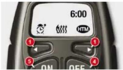
Programming the departure time
Press the buttons 1 to display the programming time.

This symbol is displayed.
Once the programming time has been displayed, press buttons 4 and 5 simultaneously within 10 seconds.

This symbol fl ashes.
Set the time by pressing the buttons 1 and press buttons 4 and 5 simultaneously to save it.

This symbol is displayed (fi xed).
Activation - deactivation
Once the programming time has been displayed by means of the buttons 1, press button 5 (ON) until the message "OK" appears.

When the signal has been received, the message "OK" is displayed along with the symbol "HTM".

This symbol is displayed when the heater starts.
HTM: Heat Thermo Management.
To deactivate the programming, press button 4 (OFF) until the message "OK" appears.

The symbol "HTM" is switched off.
When carrying out these operations, if the message "FAIL" appears, the signal has not been received. Repeat the procedure after changing your location.
Switching off the heating
Press button 5 (ON).

The symbol "HTM" remains on.
Changing the level of heating
The system offers 5 levels of heating (from the lowest level C1 to the highest level C5).
Once the level of heating has been displayed by means of the buttons 1, press buttons 4 and 5 simultaneously.
The letter "C" flashes.
Set the level of heating by pressing the buttons 1.
Press buttons 4 and 5 simultaneously to save the level selected. The letter "C" is displayed (fi xed).
The factory pre-sets are replaced by the new settings entered. The programmed times are stored until the next time they are changed.
When the departure time is activated, the level of heating cannot be changed. The departure time must be deactivated first.
COMFORT
Changing the battery
The remote control is supplied by a 6V-28L battery, which is supplied.
Information on the display indicates when it is time to replace this battery.
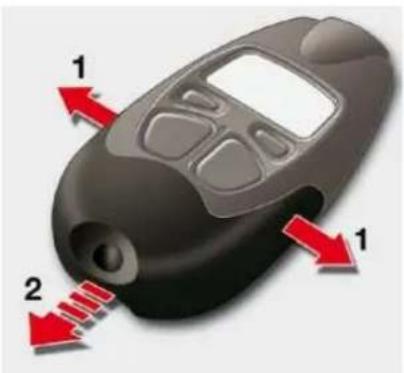
Unclip the casing then replace the battery.
The remote control must then be reinitialised, see below.

Do not discard the used batteries, take them to an approved collection point.
Reinitialising the remote control
If the vehicle's battery is disconnected or the remote control's battery is replaced, the remote control must be reinitialised.
After switching on the power, press button 4 (OFF) for 1 second within the next 5 seconds. If the operation has taken place correctly the message "OK" is displayed on the remote control screen.
If a problem occurs, the message "FAIL" appears. Repeat the operation.
In addition, your programmable heating can be to pre-heat your vehicle's passenger compartment.
natural_image
Illustration of a black handheld device with red arrows indicating directional flow or movement (no text or symbols)The interior volumetric protection alarm movement sensor may be disturbed by the flow of air from the programmable heating when it is in operation.
To avoid any unexpected triggering of the alarm during use of the programmable heating, it is advisable to deactivate the interior volumetric protection.


Always switch off the programmable heating while filling with fuel to avoid any risk of fire or explosion.
To avoid any risk of poisoning and asphyxiation, the programmable heating must not be used, even for short periods, in an enclosed space such as a garage or workshop which is not equipped with an exhaust gas extraction system.
Do not park the vehicle on an infl ammable surface (dry grass, dead leaves, paper...), there is a risk of fire.
The programmable heating system is supplied by the vehicle's fuel tank. Before use, ensure that the quantity of fuel remaining is sufficient. If the fuel tank is at the reserve, we strongly advise that you do not programme the heating.
COMFORT
FRONT SEATS
Seat consisting of a seat cushion, seat back and head restraint which can all be adjusted for optimum driving comfort.
11
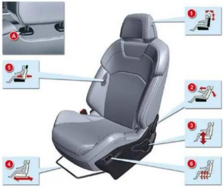
For your safety, do not drive with the head restraints removed; they must be in place and correctly adjusted.
MANUAL ADJUSTMENTS
- Adjustments to the height and angle of the head restraint
To raise it, pull upwards.
To lower it, press on the control A to unlock it, and simultaneously on the head restraint itself. The adjustment is correct when the top edge of the head restraint is at the same height as the top of the head. It is also tilt adjustable.
To raise it, press control A to unlock it, then pull it upwards. It may be necessary to adjust the backrest angle.
- Adjustment of the backrest angle
Operate the control and adjust the position of the backrest to the front or to the rear.
-
Adjustment of the seat height Raise or lower the control the number of times required to obtain the desired position.
-
Longitudinal adjustment of seat
Lift the control bar and adjust to the desired position.
- Adjustment of lumbar support
Turn the control and adjust to the desired position.
- Heated seat controls
The heated seats only operate when the engine is running.
COMFORT
FRONT SEATS
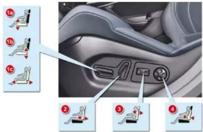
ELECTRIC ADJUSTMENTS
To adjust the electric seats, switch on the ignition or start the engine if the vehicle has gone into economy mode.
Seat adjustments are also possible for a short period after opening one of the front doors or switching off the ignition.
1. Adjustment of the seat height and angle, and longitudinal adjustment
- Raise or lower the front of the control to adjust the seat cushion angle.
- Raise or lower the rear of the control to raise or lower the seat.
Simultaneously raise or lower the front and rear of the control in order to raise or lower the entire seat.
2. Adjustment of the backrest angle
Move the control forwards or backwards to adjust the backrest angle.
3. Adjustment of the angle of the top of the backrest
Move the control forwards or backwards to adjust the angle of the top of the backrest.
4. Adjustment of lumbar support
This function allows you to independently adjust the height and level of lumbar support.
Move the control:
Forwards or backwards to increase or reduce the lumbar support.
- Upwards or downwards to raise or lower the lumbar support zone.
Head restraint height and angle adjustments on electric seats
natural_image
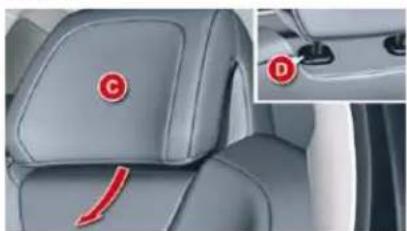
Interior view of a car seat with red circular markers and a small inset showing a red letter 'D' (no text or symbols present)To adjust the angle of the head restraint, push back or pull forward section C of the head restraint until you reach the desired position.
To raise it, pull upwards.
To lower it, press on the control D to unlock it, and simultaneously on the head restraint itself.
To remove it, press on the control D to unlock it, then pull it upwards.
COMFORT
Heated seats control
With the engine running, the front seats can operate separately.
Use the corresponding adjustment dial, placed on the outer side of each front seat, to switch on and select the level of heating required:
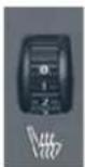
0:Off.
1: Low.
2: Medium.
3 : High.
Massage function The Welcome function
natural_image
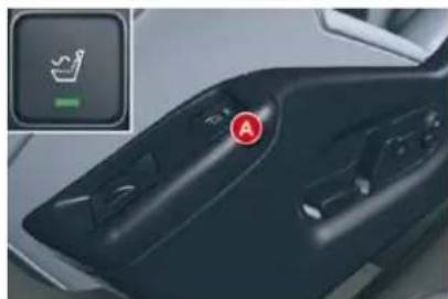
Close-up of a car's air vent with a highlighted control panel and green indicator light (no text or symbols)This function provides the driver with a back massage. It only operates when the engine is running.
Press on button A.
The warning lamp comes on and the massage function is activated for a period of 1 hour. During this time, massage is performed in cycles of 6 minutes (4 minutes of massage followed by 2 minutes break). In total, the system will perform 10 cycles.
After 1 hour, the function is deactivated. The warning lamp goes out.
Deactivation
You can deactivate the massage function at any time by pressing on button A.
The welcome function assists entry and leaving the vehicle.
After switching off the ignition and opening the driver's door, the seat moves back automatically and then stays in this position, ready for the next entry to the vehicle.
When switching on the ignition, the seat moves forward to the memorised driving position.
When moving the seat, take care that no person or object hinders the automatic movement of the seat.
This function is deactivated by default. You may activate or deactivate this function using the "Main Menu" on the instrument panel screen. To do so, select "Vehicle parameters/Comfort/Driver welcome".
COMFORT
Storing driving positions
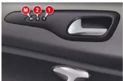
System which takes into account the settings of the driver's seat and air conditioning. It enables you to store up to two positions using the buttons on the side of the driver's seat.
Storing a position
Using buttons M/1/2
Switch on the ignition.
Adjust your seat.
Press button M, then press button 1 or 2 within four seconds.
An audible signal is heard indicating that the settings have been stored.
Storing a new position cancels the previous position.
For your safety, avoid storing a driving position while driving.
Recalling a stored position
Ignition on or engine running
Briefly press button 1 or 2 to recall the corresponding position.
An audible signal is heard indicating the end of the adjustment.
When the ignition is on, after a few consecutive position recalls, the function will be deactivated until the engine is started, to prevent discharging of the battery.
REAR HEAD RESTRAINTS
natural_image
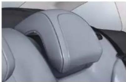
Close-up of a car seatbelt with gray plastic bands and black buttons (no text or symbols visible)The rear head restraints can be removed and have two positions:
- high, position for use,
- low, storage position.
To raise a head restraint, pull it upwards.
To lower it, press the lug then the head restraint.
To remove it, place it in the high position, push the lug and pull it upwards.
To refi t it, engage the head restraint rods in the holes taking care to remain in line with the seat back.
Never drive with the head restraints removed, they must be in place and correctly adjusted.
COMFORT
Storing driving positions
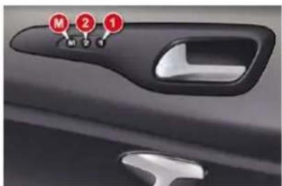
System which takes into account the settings of the driver's seat and air conditioning. It enables you to store up to two positions using the buttons on the side of the driver's seat.
Storing a position
Using buttons M/1/2
Switch on the ignition.
Adjust your seat.
Press button M, then press button 1 or 2 within four seconds.
An audible signal is heard indicating that the settings have been stored.
Storing a new position cancels the previous position.
For your safety, avoid storing a driving position while driving.
Recalling a stored position
Ignition on or engine running
Briefly press button 1 or 2 to recall the corresponding position.
An audible signal is heard indicating the end of the adjustment.
When the ignition is on, after a few consecutive position recalls, the function will be deactivated until the engine is started, to prevent discharging of the battery.
REAR HEAD RESTRAINTS
natural_image
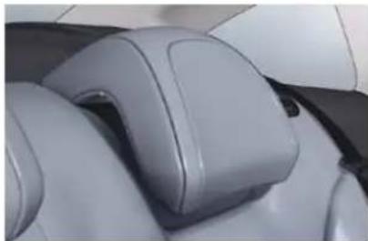
Close-up of a car seatbelt with gray plastic bands and black buttons (no text or symbols visible)The rear head restraints can be removed and have two positions:
- high, position for use,
- low, storage position.
To raise a head restraint, pull it upwards.
To lower it, press the lug then the head restraint.
To remove it, place it in the high position, push the lug and pull it upwards.
To refi t it, engage the head restraint rods in the holes taking care to remain in line with the seat back.
Never drive with the head restraints removed, they must be in place and correctly adjusted.
COMFORT
REAR SEATS
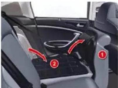
natural_image
Interior view of a car showing seat, dashboard, and seatbelt with numbered arrows indicating components (no text or symbols present)Bench seat, the left-hand (2/3) or right-hand (1/3) section of which can be folded to adapt the boot load space.
Removing the seat cushion
Move the corresponding front seat forwards if necessary.
- Raise the front of the seat cushion 1.
Tilt the seat cushion 1 fully against the front seat.
Remove the seat cushion 1 from its fi xings by pulling upwards.
Refitting the seat cushion
Position the seat cushion 1 vertically in its fixings.
Fold down the seat cushion 1.
Press on the seat cushion to secure it.
Folding the seat
In order to fold a rear seat without any risk of damage, always start with the seat cushion, never with the seat back:
move the corresponding front seat forwards if necessary,
raise the front of the seat cushion 1,
tilt the seat cushion 1 fully against the front seat,
check that the seat belt is positioned correctly on the side of the seat back,
lower or remove the head re-
straints if necessary,
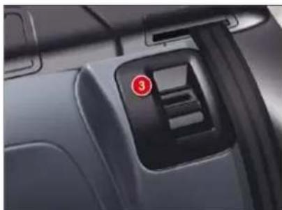
pull the control 3 forwards to release the seat back 2,
F tilt the seat back 2.
The seat cushion 1 can be removed to increase the loading volume.
Returning the seat back to its original position
When returning the rear seat to its original position:
put the seat back 2 in the upright position and secure it,
fold the seat cushion 1,
refit the head restraints or put them back in place.
When returning the rear seat to its original position, take care not to trap the seat belts and ensure that their buckles are positioned correctly.
natural_image
Close-up of a car interior showing the front and side panels with a red indicator button (no text or symbols visible)The red indicator on the control 3 should no longer be visible; if it is, push the seat fully back.
COMFORT
MIRRORS
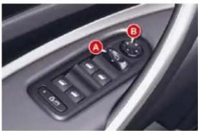
natural_image
Close-up of a car's interior control panel with labeled buttons (A and B), no readable text or symbols beyond labelsDoor mirrors
Each fitted with an adjustable mirror glasses providing the lateral rearward vision necessary for overtaking or parking. They can also be folded.
The objects observed are, in reality, closer than they appear.
Take this into account in order to correctly judge the distance of vehicles approaching from behind.
Demisting/defrosting of the door mirrors is associated with that of the rear screen.
Folding
from outside; lock the vehicle using the remote control or the key.
from inside; with the ignition on, pull control A rearwards.
If the mirrors are folded using control A, they will not unfold when the vehicle is unlocked. Control A must be pulled again.
Adjustment
With the ignition on:
- move control A to the right or to the left to select the corresponding mirror,
move control B in all four directions to adjust,
return control A to the central position.
Unfolding
from outside; unlock the vehicle using the remote control or the key.
from inside; with the ignition on, pull control A rearwards.
If the position is changed manually, a long press on control A re-engages the mirror.
The folding and unfolding of the exterior mirrors using the remote control can be deactivated by a CITROËN dealer.
COMFORT
Rear view mirror
Adjustable mirror providing a central rearward view.
Equipped with an anti-dazzle system, useful in poor light.
Manual day/night model
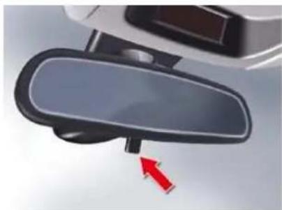
natural_image
Close-up of a car rearview mirror with a red arrow pointing to the side (no text or symbols visible)Adjustment
Adjust the mirror so that the glass is directed correctly in the "day" position.
Day/night position
Pull the lever to change to the "night" anti-dazzle position.
Push the lever to change to the normal "day" position.
As a safety precaution, the mirrors must be adjusted to reduce the "blind spot".
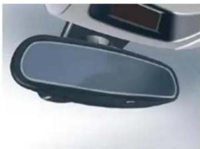
Automatic day/night model
natural_image
Close-up of a black and white object with a glossy surface, possibly a device or sensor component (no visible text or symbols)By means of a sensor, which measures the light from the rear of the vehicle, this system automatically and progressively changes between the day and night uses.
It has an anti-dazzle system which darkens the mirror glass: this reduces any driver discomfort caused by the light beam of following vehicles, the sun...
In order to guarantee optimum visibility during your manoeuvres, the mirror lightens automatically when reverse gear is engaged.
STEERING WHEEL ADJUSTMEN
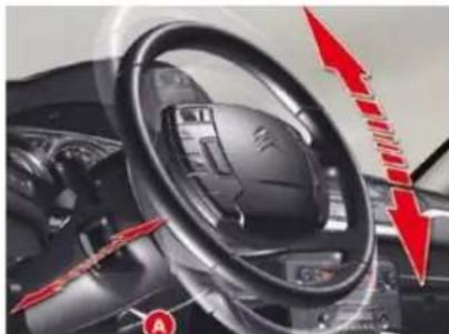
The steering wheel can be adjusted for height and reach to adapt the driving position to the size of the driver.
natural_image
Close-up of a car dashboard with red arrows indicating direction, no visible text or symbolsAdjustment
First, adjust the driver's seat to the most suitable position.
When stationary, pull the lever A to unlock the steering wheel adjustment.
Adjust for height and reach.
Push the lever to lock the steering wheel adjustment.
After locking, if you press firmly on the steering wheel, a slight click may be heard.
As a safety precaution, these operations must only be carried out while the vehicle is stationary.
OPENINGS
REMOTE CONTROL KEY
System which permits central un-locking or locking of the vehicle using the lock or from a distance. It is also used to locate and start the vehicle and provide guide-me-home lighting, as well as providing protection against theft.
Unlocking the vehicle
natural_image
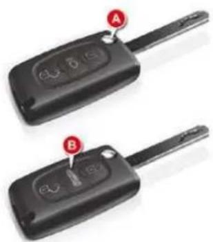
Two black car key holders with labeled buttons (A and B), no visible text or symbols beyond labelsUnfolding the key
First press button A to unfold the key.
Complete unlocking using the remote control

Press the open padlock to unlock the vehicle.
Complete unlocking using the key
Turn the key to the left in the driver's door lock to unlock the vehicle.
Unlocking is confirmed by rapid flashing of the direction indicators for approximately two seconds and lighting of the courtesy lamp (if the function is activated).
According to version, the door mirrors unfold at the same time.
Selective unlocking using the remote control

Press the open pad-lock once to unlock the driver's door only.
Press the open padlock again to unlock the other doors and the boot.
Each unlocking is confirmed by rapid flashing of the direction indicators for approximately two seconds and by switching on of the courtesy lamp.
According to version, the exterior mirrors unfold at the same time as the first unlocking action.
The complete or selective unlocking parameter is set via the instrument panel screen configuration menu (see "Instruments and controls" section).
Complete unlocking is activated by default.
Selective unlocking is not possible using the key.
Electric boot opening

Press button B to open the boot.
OPENINGS
Locking the vehicle
Normal locking using the remote control

Press the closed pad-lock to lock the vehicle completely.
Press the closed padlock for more than two seconds to close the windows and sunroof automatically in addition to locking.
Normal locking using the key
Turn the key to the right in the driver's door lock to lock the vehicle completely.
Locking is confirmed by fixed lighting of the direction indicators for approximately two seconds and by switching off of the courtesy lamp.
According to version, the exterior mirrors fold at the same time.
If one of the doors, the rear screen or the boot is still open, the central locking does not take place.
When the vehicle is locked, if it is unlocked inadvertently, it will relock automatically after thirty seconds unless a door is opened.
When stationary with the engine off, locking is confirmed by flashing of the interior locking control indicator lamp.
The folding and unfolding of the exterior mirrors using the remote control can be deactivated by a CITROËN dealer.
Deadlocking using the remote control

Press the closed pad-lock to lock the vehicle completely or press the closed padlock for more than two seconds to close the windows and sunroof automatically in addition to locking.
Press the closed padlock again within five seconds to deadlock the vehicle.
Deadlocking using the key
Turn the key to the right in the driver's door lock to lock the vehicle completely and hold it in this position for more than two seconds to close the windows automatically in addition to locking.
Turn the key to the right again within five seconds to deadlock the vehicle.
Deadlocking is confirmed by fixed lighting of the direction indicators for approximately two seconds.
According to version, the exterior mirrors fold at the same time.
Deadlocking renders the exterior and interior door controls inoperative.
It also deactivates the manual central control button.
When stationary with the engine off, locking is confirmed by flashing of the indicator lamp on the interior locking control.
If one of the doors or the boot is open or has not been closed correctly, the central locking will not work.
Therefore, never leave anyone inside the vehicle when it is dead-locked.
OPENINGS
Folding the key
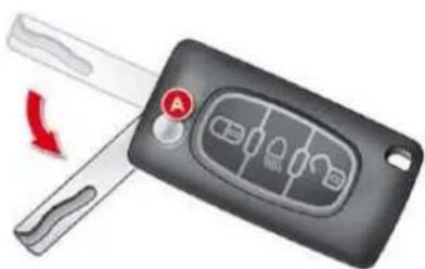
natural_image
Close-up of a black car key with a red circular button labeled 'A' and a red curved arrow indicating rotation (no text or symbols on the main object)First press button A to fold the key.
Locating your vehicle
Press the closed padlock to locate your locked vehicle in a car park.
This is indicated by switching on of the interior lighting and flashing of the direction indicators for a few seconds.
The vehicle remains locked.
Guide-me-home lighting

A press on button B operates the guide-me-home lighting (lighting of the sidelamps, dipped beams and number plate lamps).
A second press before the end of the timing cancels the guide-me-home lighting.
The timed duration can be set via the "Lighting" menu on the "Main Menu" of the instrument panel screen.
Anti-theft protection
Electronic engine immobiliser
The key contains an electronic chip which has a special code. When the ignition is switched on, this code must be recognised in order for starting to be possible.
This electronic engine immobiliser locks the engine management system a few minutes after the ignition is switched off and prevents starting of the engine by anyone who does not have the key.
SERVICE
In the event of a malfunction, you are informed by lighting of this warning lamp, an
al and a message on ion screen.
In this case, your vehicle does not start; contact a CITROËN dealer as soon as possible.
OPENINGS
IGNITION SWITCH
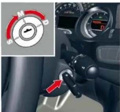
1. "S": Steering lock
To unlock the steering, gently move the steering wheel while turning the key, without forcing it.
2. "M": Drive position
Depending on the version of your vehicle, the orange and red warning lamps should also come on for a short time.
3. "D": Starter
Release the key as soon the engine has started.
If the first attempt fails, switch off the ignition. Wait ten seconds then operate the starter again.
Steering lock
-
"S": After removing the key, turn the steering wheel to lock the steering. The key can only be removed in position S.
-
"M": Ignition switched on, the steering is unlocked (by turning the key to position M, move the steering wheel gently if necessary).
-
"D": Starter position.
Never turn the key to this position when the engine is running.
Do not run the engine in an enclosed space or where there is insufficient ventilation.
It is essential always to drive with the engine running in order to retain braking and steering assistance.
Never remove the ignition key before the vehicle has come to a complete stop.
Avoid attaching a heavy object to the key which would weigh down on its shaft in the switch and could cause a malfunction.
STOPPING
Vehicles equipped with a turbocharger
Never stop the engine without having allowed it to run for a few seconds at idle, this being the time required for the turbocharger to return to a normal speed.
Do not flick the accelerator at the moment of switching off the ignition. This could cause serious damage to the turbocharger(s).
OPENINGS
Malfunction
Following disconnection of the vehicle battery, replacement of the remote control battery or in the event of a remote control malfunction, you can no longer unlock, lock or locate your vehicle.
First of all, use the key in the lock to unlock or lock your vehicle.
Then, reinitialise the remote control.
If the problem persists, contact a CITROËN dealer as soon as possible.
Reinitialisation
Switch off the ignition.
Turn the key to position 2 (Drive).
Press the closed padlock immediately for a few seconds, until the operation requested is triggered.
Switch off the ignition and remove the key from the ignition switch.
The remote control is fully operational again.
Changing the battery
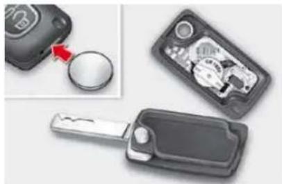
natural_image
Close-up of a smart key with a rotary knob and internal components, no visible text or symbolsBattery ref.: CR0523/3 volts.
This replacement battery is available from CITROËN dealers.
SERVICE
If the battery is flat, you are informed by lighting of this warning lamp, an audible
signal and a message on the multifunction screen.
Unclip the casing using a coin at the notch.
Slide the fl at battery out of its location.
Slide the new battery into its location observing the original direction.
Clip the casing.
Reinitialise the remote control.
OPENINGS
Lost keys
Visit a CITROËN dealer with the vehicle's V5 registration document and your personal identification documents.
The CITROËN dealer will be able to retrieve the key code and the transponder code required to order a replacement key.
Remote control
The high frequency remote control is a sensitive system; do not operate it while it is in your pocket as there is a possibility that it may unlock the vehicle, without you being aware of it.
Do not repeatedly press the buttons of your remote control out of range and out of sight of your vehicle. You run the risk of stopping it from working and the remote control would have to be reinitialised.
The remote control does not operate when the key is in the ignition, even when the ignition is switched off, except for reinitialisation.
Locking the vehicle
Driving with the doors locked may make access to the passenger compartment by the emergency services more difficult in an emergency.
As a safety precaution (with children on board), remove the key from the ignition when you leave the vehicle, even for a short time.
Anti-theft protection
Do not make any modifications to the electronic engine immobiliser system; this could cause malfunctions.
When purchasing a second-hand vehicle
Have the key codes memorised by a CITROËN dealer, to ensure that the keys in your possession are the only ones which can start the vehicle.

Do not throw the remote control batteries away, they contain metals which are harmful to the environment.
Take them to an approved collection point.
OPENINGS
Folding the key
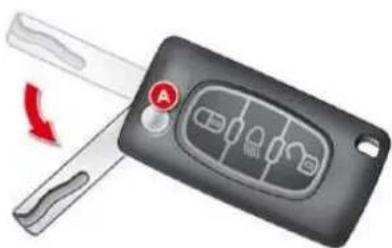
natural_image
Close-up of a black car key with a red circular button labeled 'A' and a red arrow indicating rotation (no text or symbols on the main object)First press button A to fold the key.
Locating your vehicle
Press the closed padlock to locate your locked vehicle in a car park.
This is indicated by switching on of the interior lighting and flashing of the direction indicators for a few seconds.
The vehicle remains locked.
Guide-me-home lighting

A press on button B operates the guide-me-home lighting (lighting of the sidelamps, dipped beams and number plate lamps).
A second press before the end of the timing cancels the guide-me-home lighting.
The timed duration can be set via the "Lighting" menu on the "Main Menu" of the instrument panel screen.
Anti-theft protection
Electronic engine immobiliser
The key contains an electronic chip which has a special code. When the ignition is switched on, this code must be recognised in order for starting to be possible.
This electronic engine immobiliser locks the engine management system a few minutes after the ignition is switched off and prevents starting of the engine by anyone who does not have the key.
SERVICE
In the event of a malfunction, you are informed by lighting of this warning lamp, an
al and a message on ion screen.
In this case, your vehicle does not start; contact a CITROËN dealer as soon as possible.
OPENINGS
Lost keys
Visit a CITROËN dealer with the vehicle's V5 registration document and your personal identification documents.
The CITROËN dealer will be able to retrieve the key code and the transponder code required to order a replacement key.
Remote control
The high frequency remote control is a sensitive system; do not operate it while it is in your pocket as there is a possibility that it may unlock the vehicle, without you being aware of it.
Do not repeatedly press the buttons of your remote control out of range and out of sight of your vehicle. You run the risk of stopping it from working and the remote control would have to be reinitialised.
The remote control does not operate when the key is in the ignition, even when the ignition is switched off, except for reinitialisation.
Locking the vehicle
Driving with the doors locked may make access to the passenger compartment by the emergency services more difficult in an emergency.
As a safety precaution (with children on board), remove the key from the ignition when you leave the vehicle, even for a short time.
Anti-theft protection
Do not make any modifications to the electronic engine immobiliser system; this could cause malfunctions.
When purchasing a second-hand vehicle
Have the key codes memorised by a CITROËN dealer, to ensure that the keys in your possession are the only ones which can start the vehicle.

Do not throw the remote control batteries away, they contain metals which are harmful to the environment.
Take them to an approved collection point.
OPENINGS
IGNITION SWITCH
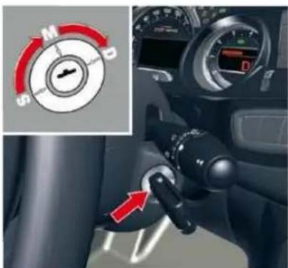
1. "S": Steering lock
To unlock the steering, gently move the steering wheel while turning the key, without forcing it.
2. "M": Drive position
Depending on the version of your vehicle, the orange and red warning lamps should also come on for a short time.
3. "D": Starter
Release the key as soon the engine has started.
If the first attempt fails, switch off the ignition. Wait ten seconds then operate the starter again.
Steering lock
-
"S": After removing the key, turn the steering wheel to lock the steering. The key can only be removed in position S.
-
"M": Ignition switched on, the steering is unlocked (by turning the key to position M, move the steering wheel gently if necessary).
-
"D": Starter position.
Never turn the key to this position when the engine is running.
Do not run the engine in an enclosed space or where there is insufficient ventilation.
It is essential always to drive with the engine running in order to retain braking and steering assistance.
Never remove the ignition key before the vehicle has come to a complete stop.
Avoid attaching a heavy object to the key which would weigh down on its shaft in the switch and could cause a malfunction.
STOPPING
Vehicles equipped with a turbocharger
Never stop the engine without having allowed it to run for a few seconds at idle, this being the time required for the turbocharger to return to a normal speed.
Do not flick the accelerator at the moment of switching off the ignition. This could cause serious damage to the turbocharger(s).
OPENINGS
ALARM
System which protects and provides a deterrent against theft and break-ins. It provides the following types of monitoring.
Exterior perimeter
The system checks for opening of the vehicle.
The alarm is triggered if anyone tries to open a door, the boot, the bonnet...
- Interior volumetric
The system checks for any variation in the volume in the passenger compartment.
The alarm is triggered if anyone breaks a window, enters the passenger compartment or moves inside the vehicle.
- Tilt
The system checks for any change in the attitude of the vehicle.
The alarm is triggered if the vehicle is lifted, moved or knocked.

Self-protection function
The system checks for the putting out of service of its components.
The alarm is triggered if the battery, the central control or the wires of the siren are put out of service or damaged.
For all work on the alarm system, contact a CITROËN dealer.
Locking the vehicle with full alarm system
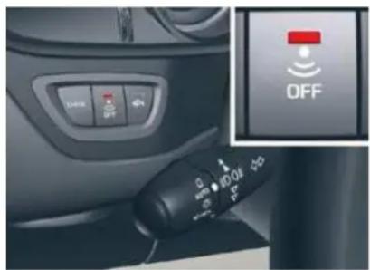
natural_image
Close-up of a car dashboard with control panel and OFF button (no readable text or symbols)Activation
Switch off the ignition and get out of the vehicle.
Press the locking button on the remote control.
The monitoring system is active: the indicator lamp on the button fl ashes once per second.
After the locking button on the remote control is pressed, the exterior perimeter monitoring is activated after a delay of 5 seconds and the interior volumetric and anti-tilt monitoring after a delay of 45 seconds.
If an opening (door, boot...) is not closed fully, the vehicle is not locked but the exterior perimeter monitoring will be activated after a delay of 45 seconds at the same time as the interior volumetric and anti-lift monitoring.
Deactivation
Press the unlocking button on the remote control.
The alarm system is deactivated: the indicator lamp on the button switches off.
Locking the vehicle with exterior perimeter monitoring only
Deactivate the interior volumetric and anti-lift monitoring to avoid unwanted triggering of the alarm in certain cases such as:
- leaving a pet in the vehicle,
- leaving a window partially open,
- washing your vehicle,
- changing a wheel,
- having your vehicle towed,
- transportation by sea.
Deactivation of the interior volumetric and anti-lift monitoring
Switch off the ignition.
Within ten seconds, press the button until the indicator lamp is lit continuously.
F Get out of the vehicle.
Press the locking button on the remote control immediately.
The exterior perimeter monitoring alone is activated: the indicator lamp on the button fl ashes once per second.
To be effective, this deactivation must be carried out each time the ignition is switched off.
OPENINGS
IV
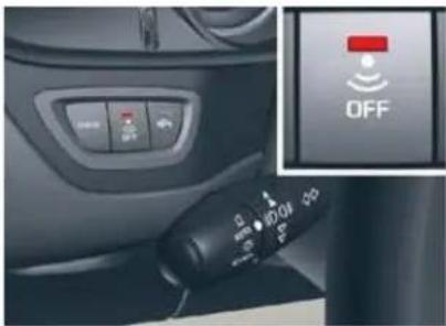
Reactivation of the interior volumetric and anti-lift monitoring
Press the unlocking button on the remote control to deactivate the exterior perimeter monitoring.
Press the locking button on the remote control to activate all the monitoring functions.
The indicator lamp on the button again fl ashes once per second.
Triggering of the alarm
This is indicated by sounding of the siren and flashing of the direction indicators for thirty seconds.
The monitoring functions remain active until the alarm has been triggered eleven times in succession.
When the vehicle is unlocked using the remote control, rapid flashing of the indicator lamp on the button informs you that the alarm was triggered during your absence. When the ignition is switched on, this flashing stops immediately.
Failure of the remote control
To deactivate the monitoring functions:
Unlock the vehicle using the key in the driver's door lock.
Open the door; the alarm is triggered.
Switch on the ignition; the alarm stops. The indicator lamp on the button switches off.
Locking the vehicle without activating the alarm
Lock or deadlock the vehicle using the key in the driver's door lock.
Malfunction
When the ignition is switched on, fi xed lighting of the indicator lamp on the button indicates a malfunction of the system.
Have it checked by a CITROËN dealer.
Automatic activation \*
2 minutes after the last door or the boot is closed, the system is activated automatically.
To avoid triggering the alarm on entering the vehicle, first press the unlocking button on the remote control.
* According to country.
OPENINGS
ELECTRIC WINDOWS
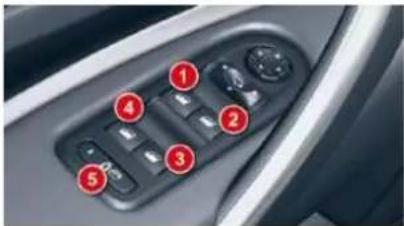
- Driver's electric window control.
- Passenger's electric window control.
- Rear right electric window control.
- Rear left electric window control.
- Deactivation of the rear electric window and door controls.
One-touch electric windows
There are two options:
- manual mode
Press or pull the control gently. The window stops when the control is released.
- automatic mode
Press or pull the control firmly. The window opens or closes fully when the control is released.
Pressing the control again stops the movement of the window.
The electric window controls remain operational for approximately 45 seconds after the ignition is switched off or until the vehicle is locked after a door is opened.
If one of the passenger windows cannot be operated from the driver's door control pad, carry out the operation from the control pad of the passenger door concerned, and vice versa.
Safety anti-pinch
When the window rises and meets an obstacle, it stops and partially lowers again.
If the window cannot be closed (for example, in the presence of ice), immediately after the movement is reversed:
press and hold the control until the window opens fully,
then pull the control immediately and hold it until the window closes,
continue to hold the control for approximately one second after the window has closed.
The safety anti-pinch function is not operational during these operations.
OPENINGS
Reinitialisation
If a window does not rise automatically, its operation must be reinitialised:
pull the control until the window stops,
release the control and pull it again until the window closes fully,
continue to hold the control for approximately one second after the window has closed,
press the control to lower the window automatically to the low position,
when the window has reached the low position, press the control again for approximately one second.
The safety anti-pinch function is not operational during these operations.
Deactivation of the rear electric window and door controls
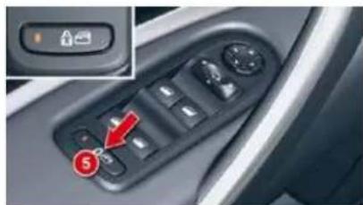
natural_image
Interior view of a car's dashboard with control buttons and a highlighted red arrow pointing to the left button (no text or symbols visible)For the safety of your children, press control 5 to deactivate the rear electric window controls regardless of their position.
Indicator lamp on, the rear controls are deactivated.
Indicator lamp off, the rear controls are activated.
A message on the instrument panel screen informs you of the activation/deactivation of the control.
This control also deactivates the interior controls for the rear doors (refer to the section "Child safety - § Electric child lock").
Any other status of the indicator lamp indicates a malfunction of the electric child lock. Have it checked by a CITROËN dealer.
Always remove the key from the ignition when leaving the vehicle, even for a short time.
If an obstacle is encountered during operation of the electric windows, you must reverse the movement of the window. To do this, press the control concerned.
When the driver operates the controls for the passengers' electric windows, he must ensure that no one is preventing correct closing of the windows.
The driver must ensure that the passengers use the electric windows correctly.
Be aware of children when operating the windows.
OPENINGS
DOORS
Opening
From outside
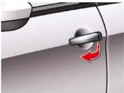
natural_image
Close-up of a car door handle with a red arrow icon on the side (no text or symbols)After unlocking the vehicle completely using the remote control or the key, pull the door handle.
When the selective unlocking is activated, the first press of the remote control unlocking button permits unlocking of the driver's door only.
From inside
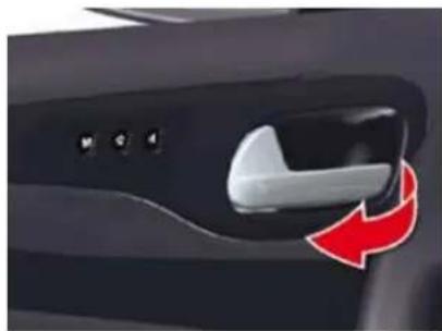
natural_image
Close-up of a car door handle with a white lever and red directional arrow (no text or symbols)Pull on the front door control to open the door; this unlocks the vehicle completely.
Pull on the rear door control to open the door; this unlocks the door concerned only.
With the selective unlocking activated:
- the driver's door control unlocks the driver's door only.
- the other door controls unlock the other doors and the boot.
The interior door controls do not operate when the vehicle is dead-locked.
Manual centralised control
System which provides full manual locking or unlocking of the doors and boot from the inside.
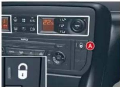
IV
Locking
Press button A to lock the vehicle.
The red indicator lamp on the button comes on. It fl ashes when the doors are locked while stationary with the engine off.
If one of the doors is open, the central locking from the inside does not take place.
OPENINGS
Unlocking
Press button A again to unlock the vehicle.
The red indicator lamp on the button switches off.
If the vehicle is locked or dead-locked from the outside, the red indicator lamp fl ashes and button A is inactive.
In this case, use the remote control or the key to unlock the vehicle.
Automatic central locking
System which provides full automatic locking or unlocking of the doors and the boot while driving.
You can activate or deactivate this function.
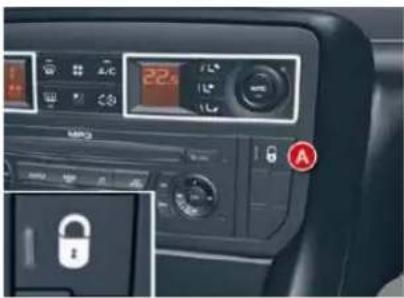
Locking
When the speed exceeds 6 mph (10 km/h), the doors and the boot lock automatically.
If one of the doors is open, the automatic central locking does not take place.
If the boot is open, the automatic central locking of the doors is active.
Unlocking
Above 6 mph (10 km/h), press button A to unlock the doors and the boot temporarily.
Activation
Press button A for more than two seconds.
A confirmation message appears on the instrument panel screen, accompanied by an audible signal.
Deactivation
Press button A again for more than two seconds.
A confirmation message appears on the instrument panel screen, accompanied by an audible signal.
Emergency control
System which locks or unlocks the doors mechanically in the event of a malfunction of the battery or of the central locking.
Locking the driver's door
Insert the key in the lock, then turn it to the right.
Unlocking the driver's door
Insert the key in the lock, then turn it to the left.
Locking the front and rear passenger doors
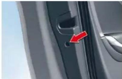
natural_image
Close-up of a car door handle with a red arrow pointing to the keyhole (no text or symbols visible)Insert the key in the lock, located on the edge of the door, then turn it one eighth of a turn.
Unlocking the front and rear passenger doors
Pull the interior door opening control.
OPENINGS
BOOT (SALOON)
Opening
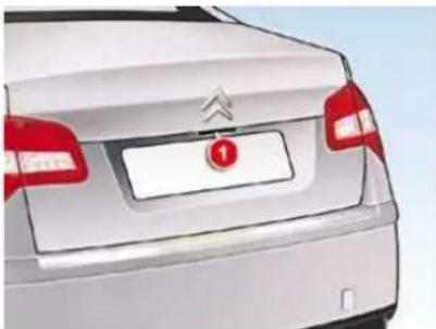
natural_image
Rear view of a white car with red and white markings, no visible text or symbolsPress upwards on lever 1 and lift up the boot lid.
Locking/unlocking
With the vehicle stationary, this is carried out using:
- The remote control.
- The key in a door lock.
- The interior central locking/un-locking control.
The boot automatically locks when the vehicle is moving at a speed of over 6 mph (10 km/h), even if automatic central locking is deactivated. It is unlocked when a door is opened or when the central locking button is pressed (speed lower than 6 mph (10 km/h)).
Emergency tailgate release
System for mechanical unlocking of the boot in the event of a battery or central locking malfunction.
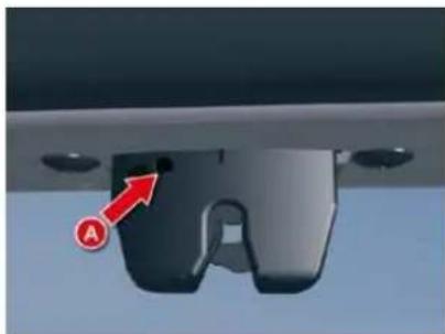
natural_image
Close-up of a car front panel with a red arrow pointing to the side panel (no text or symbols visible)IV
Unlocking
Fold back the rear seats to gain access to the lock from inside the boot.
Insert a small screwdriver into hole A of the lock to unlock the tailgate.
Push the white part, located inside the lock, to the left to unlock the boot.
OPENINGS
BOOT (TOURER)
Manual opening
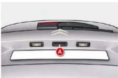
natural_image
Top-down view of a car's rear bumper with a red circular logo and three white buttons (no text or symbols visible)Press upwards on lever A and lift up the tailgate.
Electric opening
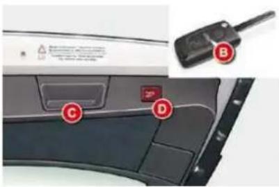
Press upwards on lever A, or press button B of the remote control.
Do not attempt to help the opening of the tailgate manually after pressing the control A.
Manual closing
Lower the tailgate using the interior handle C.
Electric closing
Press the push-button D to close the tailgate.
Do not interrupt the closing of the tailgate; if any obstacle prevents it closing, the operation will stop and the tailgate will automatically rise by a few centimetres.
Locking/unlocking
With the vehicle stationary, this is carried out using:
The remote control.
- The key in a door lock.
- The interior central locking/un-locking control.
The boot automatically locks when the vehicle is moving at a speed of over 6 mph (10 km/h), even if automatic central locking is deactivated. It is unlocked when a door is opened or when the central locking button is pressed (at a speed of less than 6 mph (10 km/h)).
Interrupting the opening/closing of the tailgate
When the tailgate is being opened or closed electrically, you can interrupt its movement at any point by pressing push-button D, the control A or button B.
You can then open or close the tailgate electrically or manually, if necessary moving it in the opposite direction to release it.
Memorisation of an intermediate position
You can store an opening angle for the tailgate:
Manually or automatically move the tailgate to the required position.
F Make a long press on push-button D. The system emits a short audible beep.
Release the push-button D.
OPENINGS
Cancelling the memorisation
With the tailgate in the intermediate position, you can cancel the stored position:
Make a long press on push-button D. The system emits a long audible beep.
Release the push-button D. The tailgate will return to the fully open position at the next use.
Electrical protection of the motor
If the tailgate is repeatedly opened and closed in quick succession, the motor can start to overheat and then cut out, preventing opening and closing of the tailgate.
Allow the motor to cool down for ten minutes without opening or closing the tailgate.
Closing in manual back-up mode remains possible.
To avoid risk of injury, make sure that no one is in the vicinity of the boot while opening and closing.
If the tailgate is carrying extra weight (snow, bicycle carrier, etc.) there is a risk of it closing under this load. Support the tailgate or first unload the bicycle carrier or clear the snow.
When using an automatic car wash, don't forget to lock the vehicle so as to avoid any risk of motorised opening of the tailgate.
OPENINGS
PANORAMIC SUN (SALOON)
Operation
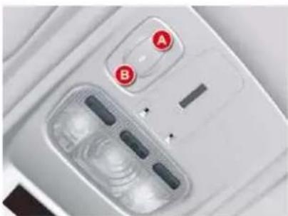
natural_image
Close-up of a white electronic device with two labeled buttons (A and B) and internal components, no readable text or symbols beyond labels.Sunroof closed
- Press B to first notch: tilting.
- Press B to second notch: automatic complete tilting.
- Press A to first notch: sliding towards rear.
- Press A to second notch: automatic total sliding towards rear.
Sunroof open
- Press B to first notch: closure.
- Press B to second notch: automatic total closure.
Tilted sunroof
- Press A to first notch: closure.
- Press A to second notch: automatic total closure.
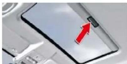
natural_image
Close-up of a smartphone with a red arrow pointing to its screen (no visible text or symbols)Your sun roof is fitted with a manually-operated blind.
Anti-pinch
An anti-pinch device stops the sun roof from closing, whether sliding or tilting. If it meets an obstacle, it re-opens.
Reinitialisation
After a battery disconnection or if there has been a malfunction, you have to re-initialise the anti-pinch function.
^B move control B until the roof is in the complete tilting position,
keep control B pressed down for a minimum of 1 second.
During these operations, the anti-pinch function does not operate.
Always remove the ignition key when leaving the vehicle, even if for a short time.
In the event of anything being caught by the sunroof closing, you must reverse the roof movement.
Do this by reversing the position of the control switch.
When the driver is operating the sunroof, they must always make sure that the passengers are not preventing it from closing properly.
The driver must ensure that passengers use the sunroof control correctly.
Pay special attention to where children are when operating the sunroof.
The fitting of a sunroof as an accessory is prohibited
OPENINGS
PANORAMIC SU (TOURER)
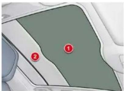
This comprises a tinted glass panoramic area 1 to improve brightness and vision in the passenger compartment.
It is fitted with an electric blind 2 to help maintain a comfortable temperature and reduce noise.
SEQUENTIAL ELECTRIC BLIND
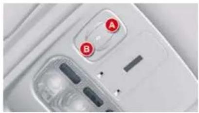
natural_image
Close-up of a white electronic device with two labeled buttons (A and B) and a transparent display case (no readable text or symbols)Opening
Press control A.
Pressing to the 1st notch allows you to open the blind step by step.
Pressing to the 2nd notch allows you to fully open the blind.
The blind stops in the closest pre-defined position (11 positions) as soon as you release the control.
Closing
Press control B.
Press to the first notch to close the blind step by step.
Press to the second notch to close the blind completely.
The blind stops at the nearest pre-set position (11 positions) as soon as you release the control.
Anti-pinch
If the blind meets an obstacle whilst closing, it stops and opens partially again.
You must re-initialise the anti-pinch function within 5 seconds of the blind stopping:
press control B until the blind is fully closed (closing in steps of a few centimetres).
After a battery disconnection, or if there has been a malfunction, you have to re-initialise the anti-pinch function:
^CB press control B to the 2nd notch (fully closed),
- wait until the blind is fully closed,
press control B for at least 3 seconds.
If the blind opens randomly during a closing operation, and straight after the blind stops:
Press control B until the blind closes fully.
During these operations, the anti-pinch function does not operate.
In the event of anything being caught when the blind is moving, you must reverse the movement of the blind. To do so, reverse the position of the control.
When the driver is operating the blind, he or she must always make sure that the passengers are not preventing it from closing properly.
The driver must ensure that passengers use the blind correctly.
Pay particular attention to children when operating the blind.
OPENINGS
FUEL TANK
Capacity of the tank: approximately 71 litres.
Low fuel level
IV

When the minimum level in the tank is reached, this warning lamp comes on in the instrument panel,
accompanied by an audible warning and a message on the multifunction screen. When it first comes on, there remains around 5 litres of fuel in the tank.
You must refuel to avoid running out of fuel.
Opening the fuel flap
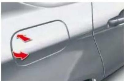
natural_image
Close-up of a car's side panel with red directional arrows on the door (no text or symbols visible)Press at the top left corner, then pull open from the left.
Refuelling
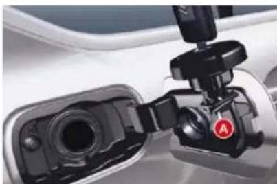
natural_image
Close-up of a car charging plug with a red circular button labeled 'A' (no visible text or symbols)turn the key a quarter turn to lock and unlock the filler cap,
when refuelling, place the cap on hook A,
fi ll the tank, but do not persist after the third cut-off ; this could cause your vehicle to malfunction.
While you are refuelling, the engine must be stopped and the ignition switched off.
For a petrol engine with a catalytic converter, unleaded fuel is compulsory.
Additions of fuel must be of at least 5 litres to be taken into account by the fuel gauge.
The filler neck is narrower to ensure that only unleaded petrol nozzles can be put in.
Opening the filler cap may create a noise of an inrush of air. This vacuum, which is entirely normal, is caused by the sealing of the fuel system.
OPENINGS
Quality of the fuel used for petrol engines
The petrol engines are perfectly compatible with E10 type petrol biofuels (containing 10% ethanol), conforming to European standards EN 228 and EN 15376.
E85 type fuels (containing up to 85 % ethanol) are reserved exclusively for vehicles marketed for the use of this type of fuel (BioFlex vehicles). The quality of the ethanol must comply with European standard EN 15293.
For Brazil only, special vehicles are marketed to run on fuels containing up to 100 % ethanol (E100 type).
Quality of the fuel used for Diesel engines
The Diesel engines are perfectly compatible with biofuels which conform to current and future European standards (Diesel fuel which complies with standard EN 590 mixed with a biofuel which complies with standard EN 14214) available at the pumps (containing up to 7% Fatty Acid Methyl Ester).
The B30 biofuel can be used in certain Diesel engines; however, this use is subject to strict application of the special servicing conditions. Consult a CITROËN dealer.
The use of any other type of (bio)fuel (vegetable or animal oils, pure or diluted, domestic fuel...) is strictly prohibited (risk of damage to the engine and fuel system).
VISIBILITY
EXTERIOR LIGHTING CONTROLS
Control stalk for the selection and control of the various front and rear lamps providing the vehicle's lighting.
Main lighting
The various front and rear lamps of the vehicle are designed to adapt the driver's visibility progressively in relation to the climatic conditions:
- sidelamps, to be seen,
- dipped beam headlamps to see without dazzling other drivers,
- main beam headlamps to see clearly when the road is clear.
Programming
Various automatic lighting control modes are also available depending on options:
- guide-me-home lighting,
- automatic lighting,
- directional lighting.
In some climatic conditions (e.g. low temperature or humidity), the presence of misting on the internal surface of the glass of the headlamps and rear lamps is normal; it disappears after the lamps have been on for a few minutes.
Additional lighting
Other lamps are fitted to fulfil the requirements of particular driving conditions:
- a rear foglamp to be seen from a distance,
- front foglamps for even better forward vision.
- directional headlamps for improved visibility when cornering,
- daytime running lamps to be seen during the day.
Manual controls
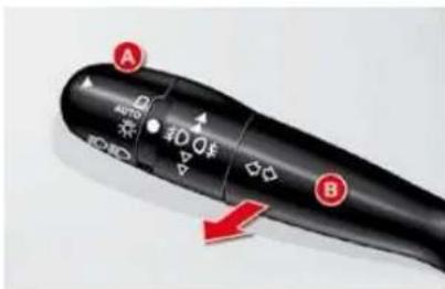
The lighting commands are issued directly by the driver by means of the ring A and the stalk B.
A. Main lighting mode selection ring, with:

lamps off,

automatic illumination of headlamps,

sidelamps only,

dipped headlamps or main beam headlamps.
B. Stalk for switching headlamps by pulling: dipped headlamps/main beam headlamps.
In the lamps off and sidelamps modes, the driver can switch on the main beam headlamps temporarily ("headlamp fl ash") by maintaining a pull on the stalk.
Displays
Lighting of the corresponding indicator lamp on the instrument panel confirms the selective switching on of the lighting selected.
VISIBILITY
C. Foglamps selection ring.
The foglamps operate with the side-lamps and the dipped and main beam headlamps.
Model with rear foglamps only
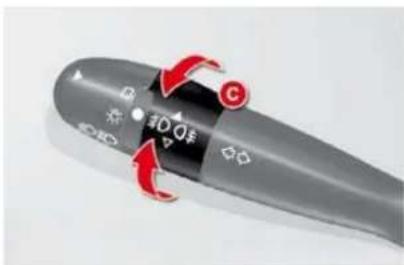
- 1 st turn forwards: rear foglamps on.
- 1 st turn rearwards: rear foglamps off.
Model with front and rear foglamps
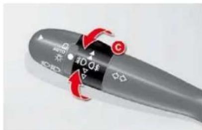
- 1 st turn forwards: front foglamps on.
- 2 nd turn forwards: rear foglamps on.
- 1 st turn rearwards: rear foglamps off.
- 2 nd turn rearwards: front foglamps off.
In good or rainy weather, both day and night, the front foglamps and the rear foglamps are prohibited. In these situations, the power of their beams may dazzle other drivers. They should only be used in fog or snow.
In these weather conditions, it is your responsibility to switch on the foglamps and dipped headlamps manually as the brightness sensor may detect sufficient light.
Do not forget to switch off the front foglamps and the rear foglamps when they are no longer necessary.
Lamps on buzzer
The triggering of an audible signal when a front door is opened warns the driver that he has forgotten to switch off his vehicle's lamps, with the ignition off and in manual lamps mode.
In this case, switching off the lamps stops the audible signal.
With the ignition off, if the dipped headlamps remain on, they will switch off automatically after thirty minutes to prevent discharging of the battery.
VISIBILITY
Daytime-running lamps
System which switches on special lamps at the front, to make the vehicle more visible by day.
They light up automatically and permanently, when the engine is running, if:
- The function is activated * in the "Main Menu" of the instrument panel screen.
- The lighting control is at position 0 or AUTO.
- All the headlamps are off.
You can deactivate * this function using the "Main Menu" of the instrument panel screen.
Manual guide-me-home lighting
Temporarily keeping the dipped beam headlamps on after the vehicle's ignition has been switched off makes the driver's exit easier when the light is poor.
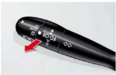
Switching on
With the ignition off, "flash" the headlamps using the lighting stalk.
A further "headlamp fl ash" switches the function off.
Switching off
The manual guide-me-home lighting switches off automatically after a set time.
Automatic illumination of headlamps
The sidelamps and dipped beam headlamps are switched on automatically, without any action on the part of the driver, when a low level of external light is detected or in certain cases of activation of the windscreen wipers.
As soon as the brightness returns to a suffi cient level or after the windscreen wipers are switched off, the lamps are switched off automatically.
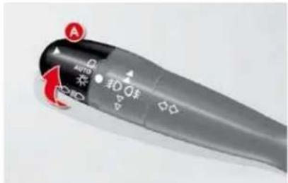
Activation
“Turn ring A to the "AUTO" position. The automatic illumination of head-lamps is accompanied by a message on the instrument panel screen.
Deactivation
Turn ring A to a position other than "AUTO". Deactivation is accompanied by a message on the instrument panel screen.
VISIBILITY
Linked with the automatic "Guide-me-home" lighting
Link with the automatic illumination of headlamps provides the "guide-me-home" lighting with the following additional options:
- selection of the duration of lighting for 15, 30 or 60 seconds in the vehicle parameters on the instrument panel screen configuration menu,
- automatic activation of "guide-me-home" lighting when automatic illumination of headlamps is in operation.
Operating fault
In the event of a malfunction of the brightness sensor, the lamps come on and a message appears on the instrument panel screen, accompanied by an audible signal.
Consult a CITROËN dealer.
In fog or snow, the brightness sensor may detect sufficient light. Therefore, the lamps will not come on automatically.
Do not cover the brightness sensor, linked with the rain sensor and located in the centre of the wind-screen behind the rear view mirror; the associated functions would no longer operate.
MANUAL HEADLADJUSTMENT
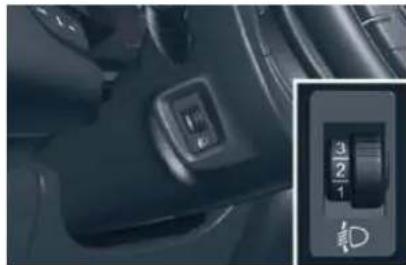
natural_image
Close-up of a car interior showing a control switch and indicator dial (no readable text or symbols)To avoid dazzling other road users, the height of the halogen bulb head-lamps must be adjusted according to the load in the vehicle.
- 1 or 2 people in the front seats.
-. 3 people. - 5 people.
- Intermediate setting.
- 5 people + maximum authorised loads.
-
Intermediate setting.
-
Driver + maximum authorised loads.
Initial setting is position "0".
AUTOMATIC ADJUSTMENT OF DIRECTIONAL HEADLAMPS
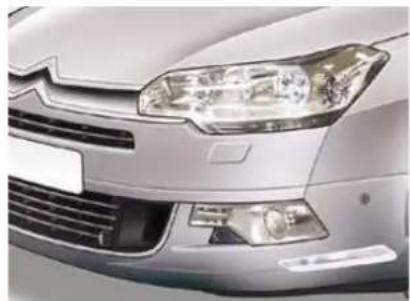
natural_image
Close-up of a silver car's front grille and headlights (no visible text or symbols)To avoid causing a nuisance to other road users, this system corrects the height of the xenon headlamp beams automatically and when stationary, depending on the load in the vehicle.
SERVICE
If a malfunction occurs, this warning lamp is displayed on the instrument panel, accompanied by an
audible signal and a message on the instrument panel screen.
The system then places your head-lamps in the lowest position.
Do not touch the xenon bulbs. Consult a CITROËN dealer.
VISIBILITY
Daytime-running lamps
System which switches on special lamps at the front, to make the vehicle more visible by day.
They light up automatically and permanently, when the engine is running, if:
- The function is activated * in the "Main Menu" of the instrument panel screen.
- The lighting control is at position 0 or AUTO.
- All the headlamps are off.
You can deactivate * this function using the "Main Menu" of the instrument panel screen.
Manual guide-me-home lighting
Temporarily keeping the dipped beam headlamps on after the vehicle's ignition has been switched off makes the driver's exit easier when the light is poor.
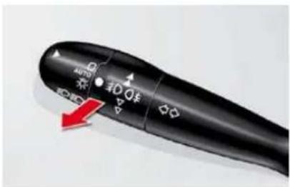
Switching on
With the ignition off, "flash" the headlamps using the lighting stalk.
A further "headlamp fl ash" switches the function off.
Switching off
The manual guide-me-home lighting switches off automatically after a set time.
Automatic illumination of headlamps
The sidelamps and dipped beam headlamps are switched on automatically, without any action on the part of the driver, when a low level of external light is detected or in certain cases of activation of the windscreen wipers.
As soon as the brightness returns to a suffi cient level or after the windscreen wipers are switched off, the lamps are switched off automatically.
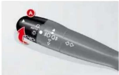
Activation
“Turn ring A to the "AUTO" position. The automatic illumination of head-lamps is accompanied by a message on the instrument panel screen.
Deactivation
Turn ring A to a position other than "AUTO". Deactivation is accompanied by a message on the instrument panel screen.
VISIBILITY
Linked with the automatic "Guide-me-home" lighting
Link with the automatic illumination of headlamps provides the "guide-me-home" lighting with the following additional options:
- selection of the duration of lighting for 15, 30 or 60 seconds in the vehicle parameters on the instrument panel screen configuration menu,
- automatic activation of "guide-me-home" lighting when automatic illumination of headlamps is in operation.
Operating fault
In the event of a malfunction of the brightness sensor, the lamps come on and a message appears on the instrument panel screen, accompanied by an audible signal.
Consult a CITROËN dealer.
In fog or snow, the brightness sensor may detect sufficient light. Therefore, the lamps will not come on automatically.
Do not cover the brightness sensor, linked with the rain sensor and located in the centre of the wind-screen behind the rear view mirror; the associated functions would no longer operate.
MANUAL HEADLADJUSTMENT
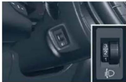
natural_image
Close-up of a car interior showing a control switch and indicator dial (no readable text or symbols)To avoid dazzling other road users, the height of the halogen bulb head-lamps must be adjusted according to the load in the vehicle.
- 1 or 2 people in the front seats.
-. 3 people. - 5 people.
- Intermediate setting.
- 5 people + maximum authorised loads.
-
Intermediate setting.
-
Driver + maximum authorised loads.
Initial setting is position "0".
AUTOMATIC ADJUSTMENT OF DIRECTIONAL HEADLAMPS
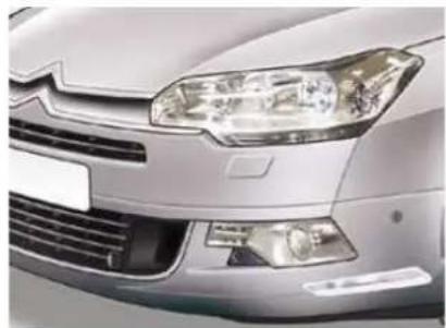
natural_image
Close-up of a silver car's front grille and headlights (no visible text or symbols)To avoid causing a nuisance to other road users, this system corrects the height of the xenon headlamp beams automatically and when stationary, depending on the load in the vehicle.
SERVICE
If a malfunction occurs, this warning lamp is displayed on the instrument panel, accompanied by an
audible signal and a message on the instrument panel screen.
The system then places your head-lamps in the lowest position.
Do not touch the xenon bulbs. Consult a CITROËN dealer.
VISIBILITY
Linked with the automatic "Guide-me-home" lighting
Link with the automatic illumination of headlamps provides the "guide-me-home" lighting with the following additional options:
- selection of the duration of lighting for 15, 30 or 60 seconds in the vehicle parameters on the instrument panel screen configuration menu,
- automatic activation of "guide-me-home" lighting when automatic illumination of headlamps is in operation.
Operating fault
In the event of a malfunction of the brightness sensor, the lamps come on and a message appears on the instrument panel screen, accompanied by an audible signal.
Consult a CITROËN dealer.
In fog or snow, the brightness sensor may detect sufficient light. Therefore, the lamps will not come on automatically.
Do not cover the brightness sensor, linked with the rain sensor and located in the centre of the wind-screen behind the rear view mirror; the associated functions would no longer operate.
MANUAL HEADLADJUSTMENT
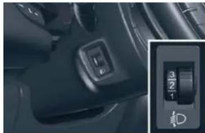
natural_image
Close-up of a car interior showing a control switch and indicator dial (no readable text or symbols)To avoid dazzling other road users, the height of the halogen bulb head-lamps must be adjusted according to the load in the vehicle.
- 1 or 2 people in the front seats.
-. 3 people. - 5 people.
- Intermediate setting.
- 5 people + maximum authorised loads.
-
Intermediate setting.
-
Driver + maximum authorised loads.
Initial setting is position "0".
AUTOMATIC ADJUSTMENT OF DIRECTIONAL HEADLAMPS
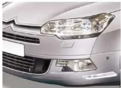
natural_image
Close-up of a silver car's front grille and headlights (no visible text or symbols)To avoid causing a nuisance to other road users, this system corrects the height of the xenon headlamp beams automatically and when stationary, depending on the load in the vehicle.
SERVICE
If a malfunction occurs, this warning lamp is displayed on the instrument panel, accompanied by an
audible signal and a message on the instrument panel screen.
The system then places your head-lamps in the lowest position.
Do not touch the xenon bulbs. Consult a CITROËN dealer.
VISIBILITY
DIRECTIONAL LIGHTING
"Cornering lighting" function
With dipped or main beams, this function provides additional lighting for the inside of a bend, when the vehicle speed is below 25 mph (approx 40 km/h).
This lighting is most useful when travelling at low and medium speed (urban driving, winding road, intersections, parking manoeuvres...).
natural_image
Top-down illustration of a car spraying water on a road with green vegetation and a circular path (no text or symbols)without cornering lighting
Deactivation
This function is deactivated:
- below a certain angle of rotation of the steering wheel,
- when stationary or at very low speed,
- when reverse gear is engaged,
- when the directional headlamps are switched off.
Activation
This function is activated:
- when the direction indicator is activated,
- from a certain angle of rotation of the steering wheel.
natural_image
Top-down illustration of a car spraying water onto a road with green grass nearby (no text or symbols)with cornering lighting
VISIBILITY
Directional headlamps function
When the dipped or main beam headlamps are on, this function, associated with the "cornering lighting" function, enables the light beam to follow the direction of the road.
The use of this function, linked with the xenon headlamps only, considerably improves the quality of your lighting when cornering.
natural_image
Top-down view of a car driving on a curved road with greenery and a person visible below (no text or symbols)without directional lighting
Programming
The function is activated or deactivated via the instrument panel screen "Main Menu".
To do this, select "Vehicle parameters\Lighting\Directional headlamps".
natural_image
Top-down illustration of a car driving on a road with a person nearby, surrounded by greenery (no text or symbols)with directional lighting
Operating fault
If a malfunction occurs, this warning lamp fl ashes on the instrument panel, accompanied by a message on the multifunction screen.
Consult a CITROËN dealer.
When stationary or moving at very low speed or when reverse gear is engaged, the function is inactive.
The status of the function remains in the memory when the ignition is switched off.
VISIBILITY
WIPER CONTROLS
System for selection and control of the various front and rear wiping modes for the elimination of rain and cleaning.
The vehicle's front and rear wipers are designed to improve the driver's visibility progressively according to the climatic conditions.
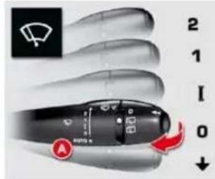
Programming
Various automatic wiper control modes are also available according to the following options:
- automatic rain sensitive wind-screen wipers,
- rear wiping on engaging reverse gear.
Manual controls
The wiper commands are issued directly by the driver by means of the stalk A and the ring B.
Windscreen wipers
A. wiping speed selection stalk:
2 fast (heavy rain),
1 normal (moderate rain),
I intermittent (proportional to the speed of the vehicle),
0 park,
single wipe (press downwards), or
AUTO ↓ automatic, then single wipe (see following page).
Rear wiper (Tourer)
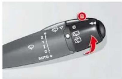
B. rear wiper selection ring:

park,

intermittent wipe,

wash-wipe (set duration).
If a significant accumulation of snow or ice is present, or when using a tailgate bicycle carrier, deactivate the automatic rear wiper via the instrument panel screen confi guration menu.
VISIBILITY
Reverse gear
When reverse gear is engaged, the rear wiper operates if the windscreen wipers are operating.
Programming
The function is activated or deactivated via the instrument panel screen configuration menu.
This function is activated by default.
Windscreen and headlamp wash
Pull the windscreen wiper stalk towards you. The windscreen wash then the windscreen wipers operate for a fixed period.
If the dipped headlamps are on, the headlamp washers operate at the same time.
Automatic rain sensitive windscreen wipers
The windscreen wipers operate automatically, without any action on the part of the driver, if rain is detected (sensor behind the rear view mirror), adapting their speed to the intensity of the rainfall.
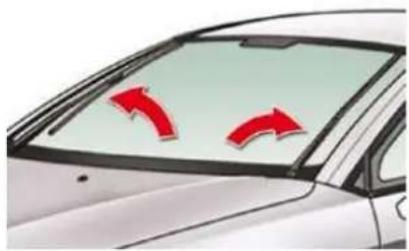
natural_image
Diagram of a car with two red curved arrows indicating clockwise motion (no text or symbols)Activation
This is controlled manually by the driver by moving stalk A to the "AUTO" position.
It is accompanied by a message on the instrument panel screen.
Switching off
This is controlled manually by the driver by moving stalk A upwards and returning it to position "0".
It is accompanied by a message on the instrument panel screen.
The automatic wiping must be reactivated if the ignition has been off for more than one minute, by pushing stalk A downwards.
Operating fault
If an automatic wiping malfunction occurs, the wipers will operate in intermittent mode.
Have it checked by a CITROËN dealer.
Do not cover the rain sensor, linked with the brightness sensor and located in the centre of the windscreen behind the rear view mirror.
Switch off the automatic wiping when using an automatic car wash.
In winter, it is advisable to wait until the windscreen is completely clear of ice before activating the automatic wiping.
VISIBILITY
Special position of the windscreen wipers
natural_image
Illustration of a car with two red directional arrows indicating clockwise motion (no text or symbols)This position permits release of the windscreen wiper blades.
It is used for cleaning or replacement of the blades. It can also be useful, in winter, to detach the blades from the windscreen.
In the moment following switching off of the ignition, any action on the stalk positions the wipers vertically on the windscreen.
To park the wipers after this has been done, switch on the ignition and operate the stalk.
For maintain the effectiveness of the "fl at-blade" wiper blades, it is advisable to:
- handle them with care,
- clean them regularly using soapy water,
- avoid using them to retain cardboard on the windscreen.
- replace them at the first signs of wear.
COURTESY LAMPS
Front courtesy lamp
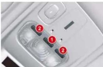
natural_image
Close-up of a white electronic device with three red-labeled buttons (1, 2, and 3) on its surface, no visible text or symbols.- Front courtesy lamp
- Map reading lamps
Rear courtesy lamp
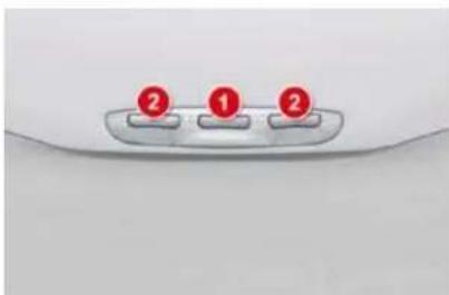
- Rear courtesy lamp
- Map reading lamps

In this position, the courtesy lamp comes on gradually:
- when the vehicle is unlocked,
- when a door is opened,
- when the key is removed from the ignition,
- when the remote control locking button is activated, in order to locate your vehicle.
It switches off gradually:
- when the vehicle is locked,
- when the ignition is switched on,
- 30 seconds after the last door is closed.

Permanently off.

Permanent lighting.
VISIBILITY
Reverse gear
When reverse gear is engaged, the rear wiper operates if the windscreen wipers are operating.
Programming
The function is activated or deactivated via the instrument panel screen configuration menu.
This function is activated by default.
Windscreen and headlamp wash
Pull the windscreen wiper stalk towards you. The windscreen wash then the windscreen wipers operate for a fixed period.
If the dipped headlamps are on, the headlamp washers operate at the same time.
Automatic rain sensitive windscreen wipers
The windscreen wipers operate automatically, without any action on the part of the driver, if rain is detected (sensor behind the rear view mirror), adapting their speed to the intensity of the rainfall.
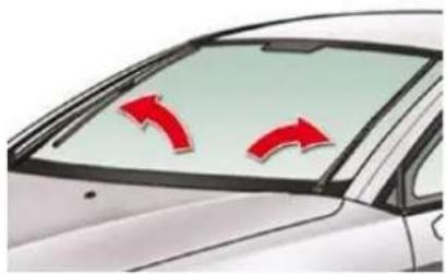
natural_image
Diagram of a car with two red curved arrows indicating clockwise motion (no text or symbols)Activation
This is controlled manually by the driver by moving stalk A to the "AUTO" position.
It is accompanied by a message on the instrument panel screen.
Switching off
This is controlled manually by the driver by moving stalk A upwards and returning it to position "0".
It is accompanied by a message on the instrument panel screen.
The automatic wiping must be reactivated if the ignition has been off for more than one minute, by pushing stalk A downwards.
Operating fault
If an automatic wiping malfunction occurs, the wipers will operate in intermittent mode.
Have it checked by a CITROËN dealer.
Do not cover the rain sensor, linked with the brightness sensor and located in the centre of the windscreen behind the rear view mirror.
Switch off the automatic wiping when using an automatic car wash.
In winter, it is advisable to wait until the windscreen is completely clear of ice before activating the automatic wiping.
VISIBILITY
Special position of the windscreen wipers
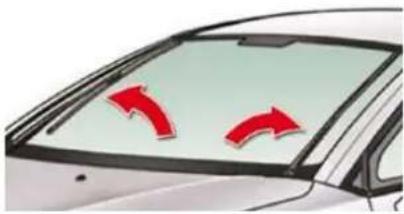
natural_image
Illustration of a car with two red directional arrows indicating clockwise motion (no text or symbols)This position permits release of the windscreen wiper blades.
It is used for cleaning or replacement of the blades. It can also be useful, in winter, to detach the blades from the windscreen.
In the moment following switching off of the ignition, any action on the stalk positions the wipers vertically on the windscreen.
To park the wipers after this has been done, switch on the ignition and operate the stalk.
For maintain the effectiveness of the "fl at-blade" wiper blades, it is advisable to:
- handle them with care,
- clean them regularly using soapy water,
- avoid using them to retain cardboard on the windscreen.
- replace them at the first signs of wear.
COURTESY LAMPS
Front courtesy lamp
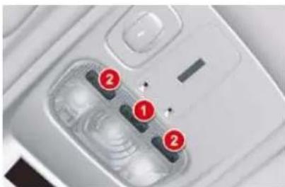
natural_image
Close-up of a white electronic device with three red-labeled buttons (1, 2, and 3) on its surface, no visible text or symbols.- Front courtesy lamp
- Map reading lamps
Rear courtesy lamp
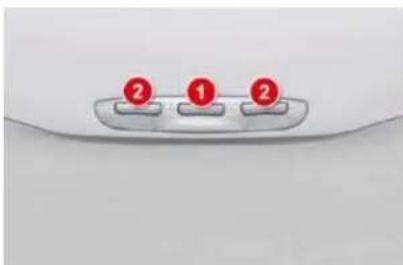
- Rear courtesy lamp
- Map reading lamps

In this position, the courtesy lamp comes on gradually:
- when the vehicle is unlocked,
- when a door is opened,
- when the key is removed from the ignition,
- when the remote control locking button is activated, in order to locate your vehicle.
It switches off gradually:
- when the vehicle is locked,
- when the ignition is switched on,
- 30 seconds after the last door is closed.

Permanently off.

Permanent lighting.
VISIBILITY
Special position of the windscreen wipers
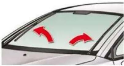
natural_image
Illustration of a car with two red directional arrows indicating clockwise motion (no text or symbols)This position permits release of the windscreen wiper blades.
It is used for cleaning or replacement of the blades. It can also be useful, in winter, to detach the blades from the windscreen.
In the moment following switching off of the ignition, any action on the stalk positions the wipers vertically on the windscreen.
To park the wipers after this has been done, switch on the ignition and operate the stalk.
For maintain the effectiveness of the "fl at-blade" wiper blades, it is advisable to:
- handle them with care,
- clean them regularly using soapy water,
- avoid using them to retain cardboard on the windscreen.
- replace them at the first signs of wear.
COURTESY LAMPS
Front courtesy lamp
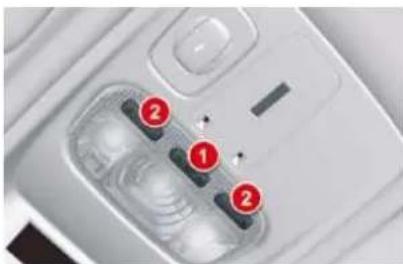
natural_image
Close-up of a smartphone camera module with numbered adjustment knobs (no text or symbols visible)- Front courtesy lamp
- Map reading lamps
Rear courtesy lamp
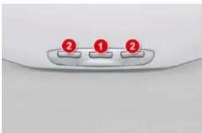
- Rear courtesy lamp
- Map reading lamps

In this position, the courtesy lamp comes on gradually:
- when the vehicle is unlocked,
- when a door is opened,
- when the key is removed from the ignition,
- when the remote control locking button is activated, in order to locate your vehicle.
It switches off gradually:
- when the vehicle is locked,
- when the ignition is switched on,
- 30 seconds after the last door is closed.

Permanently off.

Permanent lighting.
VISIBILITY
In permanent lighting mode, different lighting times are available:
- with the ignition off, approximately ten minutes,
- in energy economy mode, approximately thirty seconds,
- with the engine running, unlimited.
Map reading lamps
With the ignition on, press the corresponding switch.
Panoramic sunroof rear reading lamps (Tourer)
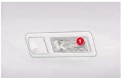
With the key in position or with the ignition on:
Press the corresponding switch. The reading lamp concerned comes on for ten minutes.
The rear reading lamps come on:
- when the key is removed from the ignition,
- when the vehicle is unlocked.
They switch off gradually:
- when the vehicle is locked,
- when the ignition is switched on.
VISIBILITY
INTERIOR MOOD LIGHTING
Your vehicle is equipped with interior mood lighting for the centre console and the door handles.

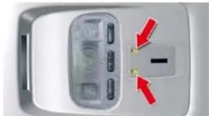
natural_image
Close-up of a device panel with buttons and a central display, showing red arrows pointing to the next button (no text or symbols visible)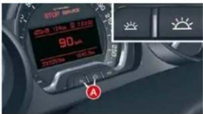
Central console
The lamps are located on the roof console, near the front interior lamp. They light up the central console.
Operation
These lamps are activated with the automatic illumination of headlamps, when the ambient light is poor. They are deactivated when the instrument panel is off.
The intensity of the lighting varies along with that of the instrument panel.
Press buttons A to increase or reduce the intensity of the lighting.
Lighting for door opening controls
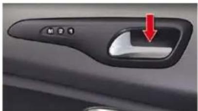
natural_image
Close-up of a car's door handle with a red arrow pointing to the left side (no text or symbols visible)They are located on the front and rear interior door opening controls.
The rear door opening controls lighting is deactivated if child safety is activated.
VISIBILITY
WELCOME LIGHTING
The welcome lighting is made up of:
- The interior (roof) lamps.
- The floor lighting.
- The pavement lighting when a door is open.
Floor lighting
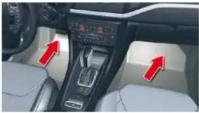
natural_image
Interior view of a car dashboard with red arrows pointing to the dashboard controls (no visible text or symbols)In the front of the vehicle, when a door is opened, this lights up the interior of the vehicle.
Pavement lighting
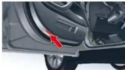
natural_image
Close-up of a car's side panel showing the wheel and door, with a red arrow pointing to the door panel (no text or symbols visible)With the door open, this lights up the ground next to the vehicle.
FITTINGS
SUN VISOR
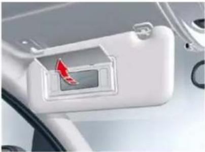
natural_image
Close-up of a car interior showing a white plastic door with a red arrow pointing to the center (no text or symbols visible)With the ignition on, lift the flap; the mirror is illuminated automatically.
To prevent dazzle from ahead, fold the visor downwards.
It can be disengaged from its central fixing and pivoted over to the side windows if required.
COOLED GLOVE BOX
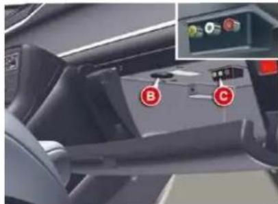
natural_image
Interior view of a car dashboard with labeled buttons (B, C) and an inset showing a control panel (no readable text or symbols)To open the glove box, pull on the handle and lower the lid.
The glove box has a manually closable air conditioning vent B.
It has 2 or 3 sockets C to connect audio/video equipment.
It has automatic illumination.
SKI FLAP
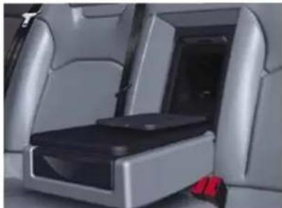
natural_image
Interior view of a car seat with black seat and silver leather seats, no visible text or symbolsA flap in the backrest, located to the rear of the armrest, facilitates the carrying of long objects.
To open
Lower the rear armrest.
Pull the fl ap handle down.
Lower the flap.
Load the objects from inside the boot.

Whilst driving, the glove box should be kept closed.
Ensure that the objects are well secured and that they do not impede the operation of the gear lever.
FITTINGS
MATS
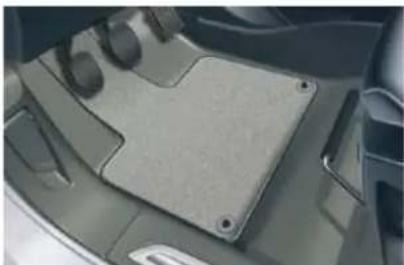
natural_image
Close-up of a car's backrest panel with visible mounting holes and side-mounted buttons (no text or symbols)Equipment available for the driver and front passenger.
Removing
- Slide the seat back as far as possible,
unclip the fi xings,
→ remove the fi xings, then the mat.
Refitting
Position the mat correctly,
clip the fi xings,
check that the mat is held is place correctly.
To avoid any interference with the pedals:
- only use mats which are suitable for the fixings already present in the vehicle. The use of these fixings is essential,
- never fit more than 1 mat.
The use of a mat not approved by CITROËN may obstruct access to the pedals and hinder the cruise control/speed limiter function.
Floor mats approved by CITROËN are fitted with a 3rd xing located in the pedal area to avoid any risk of interference with the pedals.
FRONT ARMREST
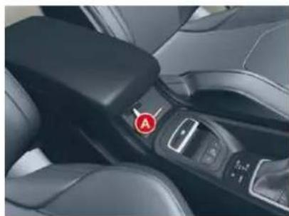
natural_image
Close-up of a car seatbelt with a red circular marker labeled 'A' on the side (no text or symbols beyond the label)Comfort and storage system for the driver and front passenger.
Adjustment
To optimise your driving position:
lift the control A,
push the armrest forwards.
The armrest returns to its initial position when you push it rearwards.
Cup-holder/USB port
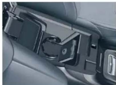
natural_image
Close-up of a car seatbelt buckle assembly (no text or symbols visible)The front armrest includes a cup holder and a USB port.
The USB port allows connection of a portable device, such as a USB memory stick, sending the audio files to your audio system so that they can be heard via the vehicle's speakers.
* Lift the armrest to access the cup holder or the USB port.
FITTINGS
Driver's oddments tray
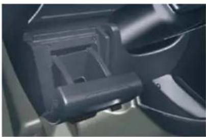
natural_image
Close-up of a mechanical component with no visible text or symbolsPull the handle towards you.
Cup-holder
The rear cup-holder A is located in the rear central armrest.
Lower the rear armrest.
Pull forwards to extract the cup-holder.
Storage
Lift up the upper part of the rear central armrest to access storage space B.
SIDE BLINDS
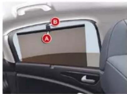
natural_image
Interior view of a car showing the front and rear panels with labeled points A and B (no text or symbols beyond labels)Pull on the tab A and position the blind on the hook B.
REAR ARMREST
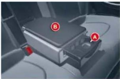
natural_image
Interior view of a car showing a car seatbelt with labeled points A and B (no text or symbols beyond labels)Comfort and storage system for the rear passengers.
12 V ACCESSORIES SOCKET
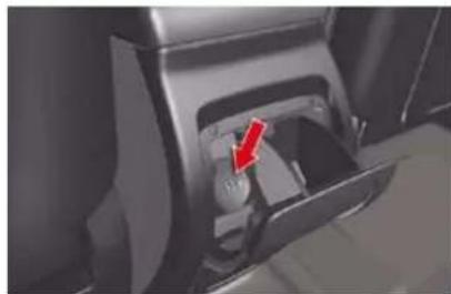
natural_image
Close-up of a mechanical component with a red arrow pointing to a small internal component (no visible text or symbols)This is located in the rear ashtray. Max power: 100 W.
REAR BLIND (SALOON
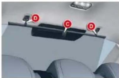
natural_image
Interior view of an airplane cockpit with three red circular markers labeled D, C, and D (no text or symbols on the main subject)pull on the tab C to unreel the blind,
position the blind on the hooks D.
FITTINGS
SUN VISOR
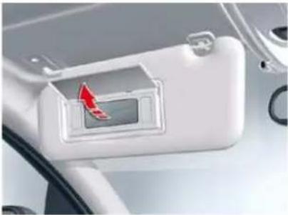
natural_image
Close-up of a car interior showing a white plastic door with a red arrow pointing to the center (no text or symbols visible)With the ignition on, lift the flap; the mirror is illuminated automatically.
To prevent dazzle from ahead, fold the visor downwards.
It can be disengaged from its central fixing and pivoted over to the side windows if required.
COOLED GLOVE BOX
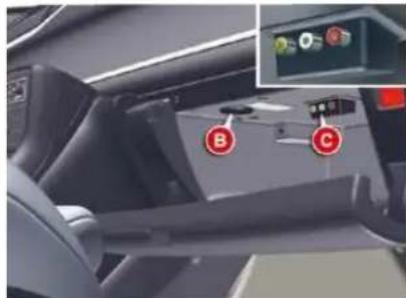
natural_image
Interior view of a car dashboard with labeled buttons (B, C) and an inset showing a control panel (no readable text or symbols)To open the glove box, pull on the handle and lower the lid.
The glove box has a manually closable air conditioning vent B.
It has 2 or 3 sockets C to connect audio/video equipment.
It has automatic illumination.
SKI FLAP
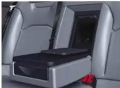
natural_image
Interior view of a car seat with black seat and silver leather seats, no visible text or symbolsA flap in the backrest, located to the rear of the armrest, facilitates the carrying of long objects.
To open
Lower the rear armrest.
Pull the fl ap handle down.
Lower the flap.
Load the objects from inside the boot.

Whilst driving, the glove box should be kept closed.
Ensure that the objects are well secured and that they do not impede the operation of the gear lever.
FITTINGS
MATS
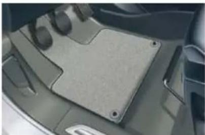
natural_image
Close-up of a car's backrest panel with visible mounting holes and side-mounted buttons (no text or symbols)Equipment available for the driver and front passenger.
Removing
- Slide the seat back as far as possible,
unclip the fi xings,
→ remove the fi xings, then the mat.
Refitting
Position the mat correctly,
clip the fi xings,
check that the mat is held is place correctly.
To avoid any interference with the pedals:
- only use mats which are suitable for the fixings already present in the vehicle. The use of these fixings is essential,
- never fit more than 1 mat.
The use of a mat not approved by CITROËN may obstruct access to the pedals and hinder the cruise control/speed limiter function.
Floor mats approved by CITROËN are fitted with a 3rd xing located in the pedal area to avoid any risk of interference with the pedals.
FRONT ARMREST
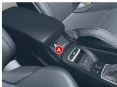
natural_image
Close-up of a car seatbelt with a red circular marker labeled 'A' on the side (no text or symbols beyond the label)Comfort and storage system for the driver and front passenger.
Adjustment
To optimise your driving position:
lift the control A,
push the armrest forwards.
The armrest returns to its initial position when you push it rearwards.
Cup-holder/USB port
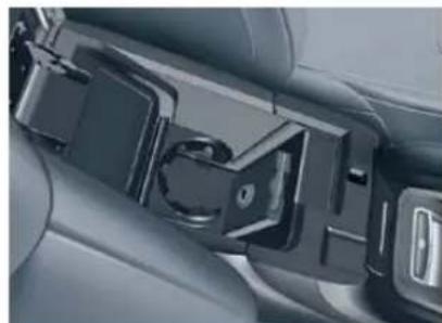
natural_image
Close-up of a car seatbelt buckle assembly (no text or symbols visible)The front armrest includes a cup holder and a USB port.
The USB port allows connection of a portable device, such as a USB memory stick, sending the audio files to your audio system so that they can be heard via the vehicle's speakers.
* Lift the armrest to access the cup holder or the USB port.
FITTINGS
MATS
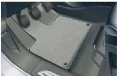
natural_image
Close-up of a car's backrest panel with visible mounting holes and side-mounted buttons (no text or symbols)Equipment available for the driver and front passenger.
Removing
- Slide the seat back as far as possible,
unclip the fi xings,
→ remove the fi xings, then the mat.
Refitting
Position the mat correctly,
clip the fi xings,
check that the mat is held is place correctly.
To avoid any interference with the pedals:
- only use mats which are suitable for the fixings already present in the vehicle. The use of these fixings is essential,
- never fit more than 1 mat.
The use of a mat not approved by CITROËN may obstruct access to the pedals and hinder the cruise control/speed limiter function.
Floor mats approved by CITROËN are fitted with a 3rd xing located in the pedal area to avoid any risk of interference with the pedals.
FRONT ARMREST
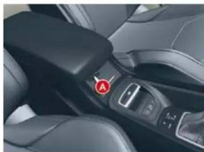
natural_image
Close-up of a car seatbelt with a red circular marker labeled 'A' on the side (no text or symbols beyond the label)Comfort and storage system for the driver and front passenger.
Adjustment
To optimise your driving position:
lift the control A,
push the armrest forwards.
The armrest returns to its initial position when you push it rearwards.
Cup-holder/USB port
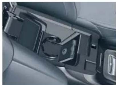
natural_image
Close-up of a car seatbelt buckle assembly (no text or symbols visible)The front armrest includes a cup holder and a USB port.
The USB port allows connection of a portable device, such as a USB memory stick, sending the audio files to your audio system so that they can be heard via the vehicle's speakers.
* Lift the armrest to access the cup holder or the USB port.
FITTINGS
Driver's oddments tray
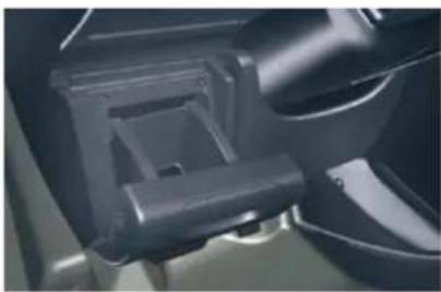
natural_image
Close-up of a mechanical component with no visible text or symbolsPull the handle towards you.
Cup-holder
The rear cup-holder A is located in the rear central armrest.
Lower the rear armrest.
Pull forwards to extract the cup-holder.
Storage
Lift up the upper part of the rear central armrest to access storage space B.
SIDE BLINDS
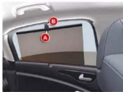
natural_image
Interior view of a car showing the front and rear panels with labeled points A and B (no text or symbols beyond labels)Pull on the tab A and position the blind on the hook B.
REAR ARMREST
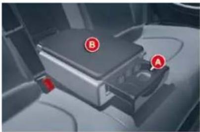
natural_image
Interior view of a car showing a car seatbelt with labeled points A and B (no text or symbols beyond labels)Comfort and storage system for the rear passengers.
12 V ACCESSORIES SOCKET
natural_image
Close-up of a mechanical component with a red arrow pointing to a small internal component (no visible text or symbols)This is located in the rear ashtray. Max power: 100 W.
REAR BLIND (SALOON
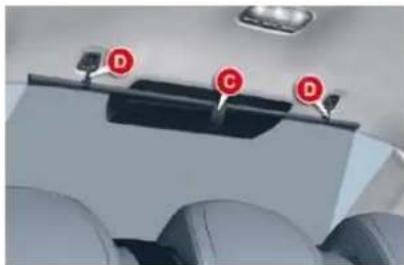
natural_image
Interior view of an airplane cockpit with three red circular markers labeled D, C, and D (no text or symbols on the main subject)pull on the tab C to unreel the blind,
position the blind on the hooks D.
FITTINGS
Driver's oddments tray
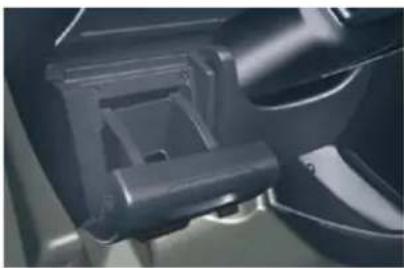
natural_image
Close-up of a mechanical component with no visible text or symbolsPull the handle towards you.
Cup-holder
The rear cup-holder A is located in the rear central armrest.
Lower the rear armrest.
Pull forwards to extract the cup-holder.
Storage
Lift up the upper part of the rear central armrest to access storage space B.
SIDE BLINDS
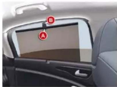
natural_image
Interior view of a car showing the front and rear panels with labeled points A and B (no text or symbols beyond labels)Pull on the tab A and position the blind on the hook B.
REAR ARMREST
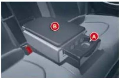
natural_image
Interior view of a car showing a car seatbelt with labeled points A and B (no text or symbols beyond labels)Comfort and storage system for the rear passengers.
12 V ACCESSORIES SOCKET
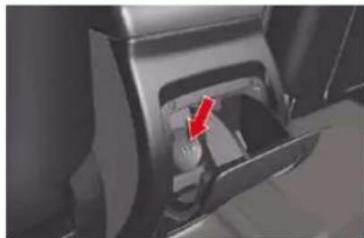
natural_image
Close-up of a mechanical component with a red arrow pointing to a small internal component (no visible text or symbols)This is located in the rear ashtray. Max power: 100 W.
REAR BLIND (SALOON
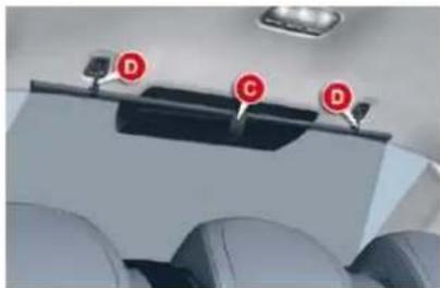
natural_image
Interior view of an airplane cockpit with three red circular markers labeled D, C, and D (no text or symbols on the main subject)pull on the tab C to unreel the blind,
position the blind on the hooks D.
FITTINGS
BOOT FITTINGS (SALOON)
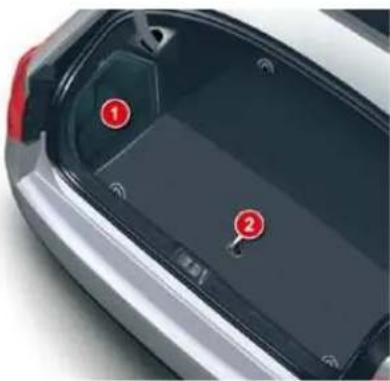
natural_image
Close-up of a car trunk with two red circular markers labeled 1 and 2, showing interior vehicle structure (no text or symbols beyond labels)-
Battery location for vehicles with V6 HDi engine.
-
Boot floor (spare wheel storage).
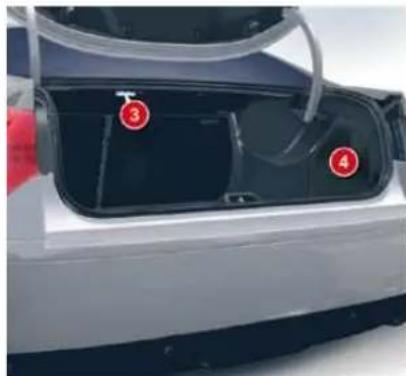
natural_image
Exterior view of a car trunk with labeled components (3, 4), no visible text or symbols beyond numbered annotations-
Boot lamp.
-
Location for 6 CD changer.
Luggage securing rings
Use the 4 securing rings on the boot floor to secure your luggage.
For safety reasons in the event of sharp braking, you are advised to place heavy objects as far forward in the boot as possible.
VI
FITTINGS
BOOT FITTINGS (TOURER)
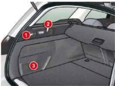
1. Hook
For shopping bags.
2. Torch
To recharge, return it to its storage position.
- Storage net or Battery compartment (for vehicles with 3 litre V6 HDi engine).
This provides access to the battery.
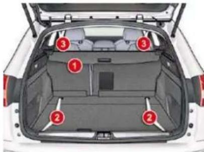
1. Luggage-cover blind
(see details on following page)
2. Luggage securing rings
Use the 4 stowing rings provided on the boot floor to secure your loads.
For safety reasons in the event of sharp braking, you are advised to place heavy objects as far forwards as possible.
3. Hooks
These allow a cargo net to be fitted (see details on following page).
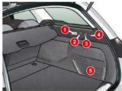
1. Boot lamp
- 12 V accessories socket (100 W maximum)
Cigar lighter type 12 volt socket. It is located on the rear right-hand trim.
3. Loading height control
You can change the height of the vehicle to make loading or un- loading easier.
4. Hook
For shopping bags.
- Storage net or closed housing Location for the 6 CD changer.
FITTINGS
LUGGAGE COVER (TOURER)
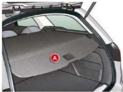
natural_image
Interior view of a car trunk with a visible rear cover and a red circular logo on the lid (no text or symbols)To roll up
Press the handle (PRESS) gently. The luggage cover rolls up automatically.
The moving part A can be folded along the rear bench seat backrest.
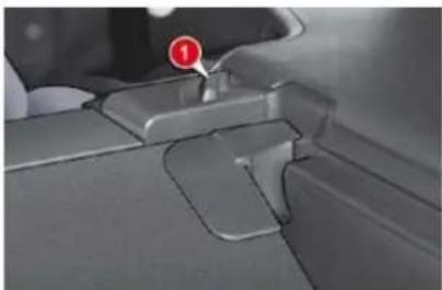
natural_image
Close-up of a mechanical component with a red circular marker labeled '1' (no text or symbols beyond the marker)To remove
Compress the control 1 and lift the luggage cover on the right then on the left to remove it.
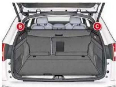
natural_image
Top-down view of a white car trunk with rear seats and open roof, marked with red circles B and C (no text or symbols on the car itself)To install
Position the left-hand end of the luggage cover roller in its location B behind the rear bench seat.
Compress the roller control 1 and put the roller in place in its location C on the right.
Release the control to secure the luggage cover.
Unroll it to its fastening on the rear pillar.
High load retaining net (Tourer)
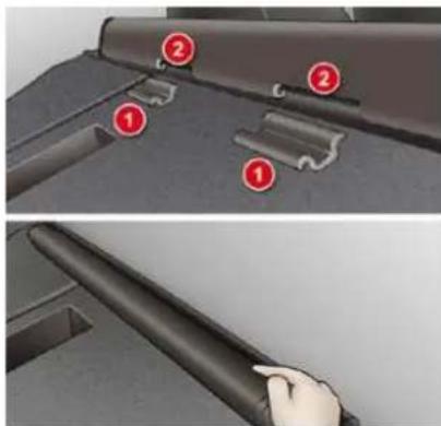
Hooked onto the special upper and lower fixings, this permits use of the entire loading volume up to the roof:
- behind the rear seats (row 2), - behind the front seats (row 1) when the rear seats are folded. When positioning the net, check that the strap loops are visible from the boot; this will make slackening or tightening easier.
FITTINGS
VI
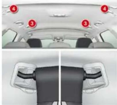
natural_image
Top-down and side-view views of a car showing rear seats and seatbelt (no text or symbols)Installation
fold down the backs of the rear seats,
position the high load retaining net roller above the two rails 1 located behind the rear seats (2/3 bench seat). The two notch-es 2 must be placed above the two rails,
slide the two rails 1 into the notches 2 and push the roller (lengthways) from right to left to secure it,
reposition the rear seat backs.
Row 1 Row 2
To use it in row 1:
fold down the backs of the rear seats,
open the covers 3 of the corresponding upper fixings,
unroll the high load retaining net and position one of the ends of the net's metal bar in the corresponding fixing cover. Check that the hook is secured in the rail located inside the cover 3,
pull the high load retaining net's metal bar to position the other hook in the second fi xing cover.
To use it in row 2:
open the covers 4 of the corresponding upper fixings,
from the rear bench seat, unroll the high load retaining net, pushing it to detach it from the retaining hooks,
position one of the ends of the net's metal bar in the corresponding fixing cover. Check that the hook is secured in the rail located inside the cover,
position the other hook in the second fi xing cover and pull the metal bar towards you.
CHILD SAFETY
GENERAL POINTS RELATING TO CHILD SEATS
Although one of CITROËN's main criteria when designing your vehicle, the safety of your children also depends on you.
For maximum safety, please observe the following recommendations:
- in accordance with European regulations, all children under the age of 12 or less than one and a half metres tall must travel in approved child seats suited to their weight, on seats fitted with a seat belt or ISOFIX mountings *,
- statistically, the safest seats in your vehicle for carrying children are the rear seats,
- a child weighing less than 9 kg must travel in the "rearwards-facing" position both in the front and in the rear.
CHILD SEAT IN THE FRONT
"Rearwards-facing"
When a "rearwards-facing" child seat is installed on the front passenger seat, it is essential that the passenger airbag is deactivated. Otherwise, the child would risk being seriously injured or killed if the airbag were to inflate.
"Forwards-facing"
When a "forwards-facing" child seat is installed on the front passenger seat, adjust the vehicle's seat to the intermediate longitudinal position with the seat back upright and leave the passenger airbag activated.
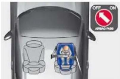
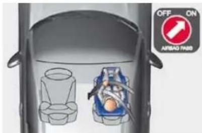
VII
CITROËN recommends that children should travel in the rear seats of your vehicle:
- "rearwards-facing" up to the age of 2,
- "forwards-facing" over the age of 2.
* The rules for carrying children are specific to each country. Refer to the current legislation in your country.
Intermediate longitudinal position
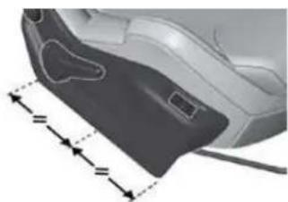
natural_image
Close-up of a car interior panel with dashed measurement lines indicating width and height (no text or symbols)CHILD SAFETY

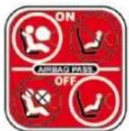
Passenger air bag OFF
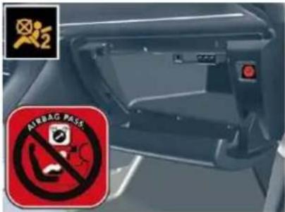
CHILD SEATS RECOMMENDED BY CITROËN
CITROËN offers a complete range of recommended child seats which are secured using a three point seat belt :
| Group 0: from birth to 10 kgGroup 0+: from birth to 13 kg | Groups 1, 2 and 3: from 9 to 36 kg | ||
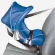 | L1"RÖMER Baby-Safe Plus"Installed in the rearwards-facing position. | 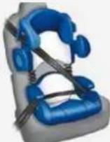 | L2"KIDDY Life"The use of the restraining cushion is compulsory for carrying young children (from 9 to 18 kg). |
| Groups 2 and 3: from 15 to 36 kg | |||
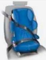 | L3"RECARO Start" | 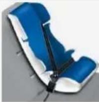 | L4"KLIPPAN Optima"From the age of 6 years (approximately 22 kg), the booster is used on its own. |
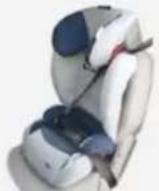 | L5"RÖMER KIDFIX"Can be fitted to the vehicle's ISOFIX anchorages.The child is restrained by the seat belt. | ||
CHILD SAFETY

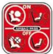
Passenger air bag OFF
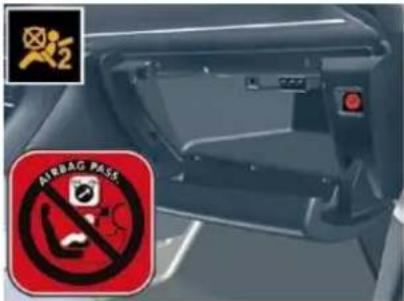
CHILD SEATS RECOMMENDED BY CITROËN
CITROËN offers a complete range of recommended child seats which are secured using a three point seat belt :
| Group 0: from birth to 10 kgGroup 0+: from birth to 13 kg | Groups 1, 2 and 3: from 9 to 36 kg | ||
| L1"RÖMER Baby-Safe Plus"Installed in the rearwards-facing position. | | L2"KIDDY Life"The use of the restraining cushion is compulsory for carrying young children (from 9 to 18 kg). |
| Groups 2 and 3: from 15 to 36 kg | |||
| L3"RECARO Start" |  | L4"KLIPPAN Optima"From the age of 6 years (approximately 22 kg), the booster is used on its own. |
 | L5"RÖMER KIDFIX"Can be fitted to the vehicle's ISOFIX anchorages.The child is restrained by the seat belt. | ||
POSITIONS FOR CHILD SEATS SECURED USING THE SEAT BELT
In conformity with European law, this table shows you the possibilities for the installation of universally approved child seats (a) using a seat belt, depending on the weight of the child and the seating position in the vehicle.
| Seat position(s) | Weight of child | ||||
| Groups 0 (c) and 0+ < 13 kg | Group 1 9 to 18 kg | Group 2 15 to 25 kg | Group 3 22 to 36 kg | ||
| Row 1 | Front passenger (b) with height adjustment | U (R) | U (R) | U (R) | U (R) |
| Front passenger (b) without height adjustment | U | U | U | U | |
| Row 2 | Outer rear | U | U | U | U |
| Centre rear | U | U | U | U | |
(a) Universal child seat: child seat which can be installed in all vehicles using the seat belt.
(b) Consult the current legislation for your country before driving with your child in this seat.
(c) Group 0: from birth to 10 kg. Shells and "car cots" cannot be installed on the front passenger seat.
U: seat position suitable for installation of universally approved rearwards-facing and/or forwards-facing child seat.
U (R): As U, with the vehicle seat, which must be adjusted to the highest position.
VII
CHILD SAFETY
"ISOFIX" MOUNTINGS
Your vehicle has been approved in accordance with the new ISOFIX regulation s.
The rear side seats and the front passenger seat are fitted with regulation ISOFIX mountings.
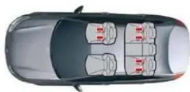
natural_image
Top-down view of a car showing four seats with red buttons, no text or symbols visibleIn the front
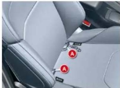
natural_image
Interior view of a car seatbelt and rearview mirror (no text or symbols visible)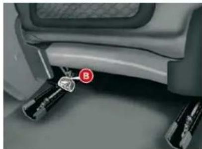
natural_image
Close-up of a car seat with visible brake feet and a red circular marker labeled 'B' (no text or symbols beyond the label)These are three rings for the front passenger seat:
- two rings A, located between the vehicle seat back and cushion, indicated by a label,
- a ring B, fixed at the bottom of the rear of the seat back, used to secure the upper strap of the child seat.
In the rear
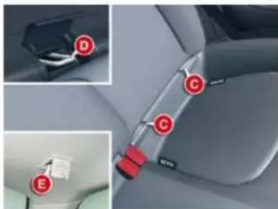
Saloon
These are three rings for each outer rear seat:
- two lower rings C, located between the vehicle seat back and cushion, indicated by a label,
- an upper ring D, fixed to the rear shelf, concealed under a flap with the logo TOP TETHER behind the head restraint.
Tourer
- two lower rings C, located between the vehicle seat back and cushion, indicated by a label,
- an upper ring E, fixed to the roof on the boot side, concealed under a flap with the logo TOP TETHER.
This ISOFIX mounting system guarantees you fast, reliable and safe fi tting of the child seat in your vehicle.
The ISOFIX child seats are fitted with two locks which are secured easily on the two rings A or C, following installation of the guides (supplied with the seat).
Some also have an upper strap which is attached to the ring B, D or E.
To attach this strap in the front, raise the vehicle seat's head restraint and pass the upper strap between the rods of the head restraint. Then fix the hook on the ring B and tighten the upper strap.
To attach this strap in the rear, remove the vehicle seat's head restraint and stow it. Lift the cover on the rear shelf (Saloon) or the roof (Tourer). Then fi x the hook on the ring D or E and tighten the upper strap.
The incorrect installation of a child seat in a vehicle compromises the child's protection in the event of an accident.
For information regarding the ISOFIX child seats which can be installed in your vehicle, consult the table of positions for fl tting ISOFIX child seats.
ADVICE ON CHILD SEATS
The incorrect installation of a child seat in a vehicle compromises the child's protection in the event of an accident.
When installing a child seat using the seat belt, check that the seat belt is tightened correctly on the child seat and that it secures the child seat firmly on the seat of your vehicle.
Remember to fasten the seat belts or the child seat harnesses keeping the slack in relation to the child's body to a minimum, even for short journeys.
For optimum installation of the "forwards-facing" child seat, ensure that the back of the child seat is in contact with the back of the vehicle's seat and that the head restraint does not cause any discomfort.
If the head restraint has to be removed, ensure that it is stored or attached securely to prevent it from being thrown around the vehicle in the event of sharp braking.
Children under the age of 10 must not travel in the "forwards-facing" position on the front passenger seat, unless the rear seats are already occupied by other children, cannot be used or are absent.
Deactivate the passenger airbag * when a "rearwards-facing" child seat is installed on the front seat. Otherwise, the child would risk being seriously injured or killed if the airbag were to inflate.
Installing a booster seat
The chest part of the seat belt must be positioned on the child's shoulder without touching the neck.
Ensure that the lap part of the seat belt passes correctly over the child's thighs.
CITROËN recommends the use of a booster seat which has a back, fitted with a seat belt guide at shoulder level.
As a safety precaution, do not leave:
- one or more children alone and unsupervised in a vehicle,
- a child or an animal in a vehicle which is exposed to the sun, with the windows closed,
- the keys within reach of children inside the vehicle.
To prevent accidental opening of the doors, use the "Child lock".
Take care not to open the rear windows by more than one third.
To protect young children from the rays of the sun, fi t side blinds on the rear windows.
* According to country and current local legislation.
This ISOFIX mounting system guarantees you fast, reliable and safe fi tting of the child seat in your vehicle.
The ISOFIX child seats are fitted with two locks which are secured easily on the two rings A or C, following installation of the guides (supplied with the seat).
Some also have an upper strap which is attached to the ring B, D or E.
To attach this strap in the front, raise the vehicle seat's head restraint and pass the upper strap between the rods of the head restraint. Then fix the hook on the ring B and tighten the upper strap.
To attach this strap in the rear, remove the vehicle seat's head restraint and stow it. Lift the cover on the rear shelf (Saloon) or the roof (Tourer). Then fi x the hook on the ring D or E and tighten the upper strap.
The incorrect installation of a child seat in a vehicle compromises the child's protection in the event of an accident.
For information regarding the ISOFIX child seats which can be installed in your vehicle, consult the table of positions for fl tting ISOFIX child seats.
ADVICE ON CHILD SEATS
The incorrect installation of a child seat in a vehicle compromises the child's protection in the event of an accident.
When installing a child seat using the seat belt, check that the seat belt is tightened correctly on the child seat and that it secures the child seat firmly on the seat of your vehicle.
Remember to fasten the seat belts or the child seat harnesses keeping the slack in relation to the child's body to a minimum, even for short journeys.
For optimum installation of the "forwards-facing" child seat, ensure that the back of the child seat is in contact with the back of the vehicle's seat and that the head restraint does not cause any discomfort.
If the head restraint has to be removed, ensure that it is stored or attached securely to prevent it from being thrown around the vehicle in the event of sharp braking.
Children under the age of 10 must not travel in the "forwards-facing" position on the front passenger seat, unless the rear seats are already occupied by other children, cannot be used or are absent.
Deactivate the passenger airbag * when a "rearwards-facing" child seat is installed on the front seat. Otherwise, the child would risk being seriously injured or killed if the airbag were to inflate.
Installing a booster seat
The chest part of the seat belt must be positioned on the child's shoulder without touching the neck.
Ensure that the lap part of the seat belt passes correctly over the child's thighs.
CITROËN recommends the use of a booster seat which has a back, fitted with a seat belt guide at shoulder level.
As a safety precaution, do not leave:
- one or more children alone and unsupervised in a vehicle,
- a child or an animal in a vehicle which is exposed to the sun, with the windows closed,
- the keys within reach of children inside the vehicle.
To prevent accidental opening of the doors, use the "Child lock".
Take care not to open the rear windows by more than one third.
To protect young children from the rays of the sun, fi t side blinds on the rear windows.
* According to country and current local legislation.
CHILD SAFETY
ISOFIX CHILD SEAT RECOMMENDED BY CITROËN AND APPROVED FOR YOUR VEHICLE
| RÖMER Duo Plus ISOFIX (size category B1) | |
| Group 1: from 9 to 18 kg | |
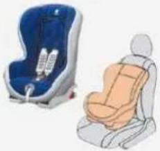 | Installed in the forwards-facing position.Fitted with an upper strap to be secured on the upper ring B, D or E, referred to as the TOP TETHER.Three seat body angles: sitting, reclining, lying. |
This child seat can also be used on seats which are not fitted with ISOFIX mountings. In this case, it must be attached to the vehicle seat using the three point seat belt. Follow the instructions for fitting the child seat given in the seat manufacturer's installation guide.
CHILD SAFETY
POSITIONS FOR FITTING ISOFIX CHILD SEATS
In conformity with European law (ECE 16), this table shows you the possibilities for the installation of ISOFIX child seats to seats in the vehicle fitted with ISOFIX mounting points.
For ISOFIX universal and semi-universal child seats, the ISOFIX size class, defined by a letter from A to G, is shown on the child seat to the right of the ISOFIX logo.
| Weight of child/ Age given as a guide | ||||||||||
| Up to 10 kg (group 0) Up to around 6 months | Up to 10 kg (group 0) Up to 13 kg (group 0+) Up to around 1 year | 9 to 18 kg (group 1) Approx 1 to 3 years | ||||||||
| Type of ISOFIX child seat | Shell | "Rearwards-facing" | "Rearwards-facing" "Forwards-facing" | |||||||
| ISOFIX size class | F | G | C | D | E | C | D | A | B | B1 |
| Universal and semi-universal ISOFIX child seats can be installed on: - Front passenger seat | X | IL-SU | IL-SU | IUF/IL-SU | ||||||
| - Outer rear seats | IL-SU* | IL-SU | IL-SU | IUF/IL-SU | ||||||
| - Centre rear seat | Non ISOFIX seat position | |||||||||
IUF: Seat position suitable for installation of an Isofix Universal "Forwards-facing" seat attached using the top tether.
IL-SU: Seat position suitable for installation of an ISOFIX Semi-Universal child seat, either:
- "rearwards-facing" fitted with an upper strap or a stay
- "forwards-facing" fitted with a stay,
- a shell fitted with an upper strap or a stay.
To attach the upper strap, refer to the "ISOFIX mountings" paragraph.
X: Seat not suitable for installation of an ISOFIX seat of the size class indicated
* The ISOFIX shell, fi xed to the lower rings of an ISOFIX seat, occupies two rear seats.
CHILD SAFETY
ELECTRIC CHILD LOCK
Remote control system to prevent opening of the rear doors using their interior controls and use of the rear electric windows.
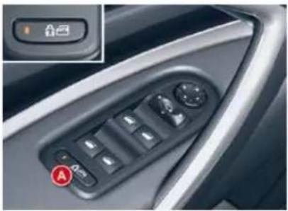
natural_image
Close-up of a car's side panel with a control knob and indicator lights (no text or symbols visible)The control is located on the driver's door, with the electric window controls.
Activation
Press button A.
The indicator lamp on button A comes on, accompanied by a message on the instrument panel screen.
Deactivation
Press button A again.
The indicator lamp on button A switches off, accompanied by a message on the instrument panel screen.
This indicator lamp remains off until the child lock is activated.
Any other status of the indicator lamp indicates a malfunction of the electric child lock. Have it checked by a CITROËN dealer.
This system is independent and in no circumstances does it take the place of the central locking control. Check the status of the child lock each time you switch on the ignition.
Always remove the key from the ignition when leaving the vehicle, even for a short time.
In the event of a serious impact, the electric child lock is deactivated automatically to permit the exit of the rear passengers.
SAFETY
DIRECTION INDICATORS
Selection of the left or right direction indicators to signal a change of direction of the vehicle.
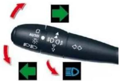
Left: lower the lighting stalk beyond the point of resistance.
Right: raise the lighting stalk beyond the point of resistance.
"Motorway" function
Press briefly upwards or downwards, without going beyond the point of resistance; the direction indicators will flash 3 times.
HAZARD WARNING LAI
A visual warning by means of the direction indicators to alert other road users to a vehicle breakdown, towing or accident.
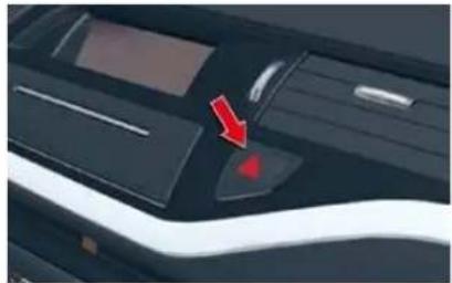
natural_image
Close-up of a car's front panel with a red arrow pointing to a button (no text or symbols visible)Press this button, the direction indicators flash.
They can operate with the ignition off.
Automatic operation of hazard warning lamps
When braking in an emergency, depending on the deceleration, the hazard warning lamps come on automatically.
They switch off automatically the first time you accelerate.
You can also switch them off by pressing the button.
HORN
Audible warning to alert other road users to an imminent danger.
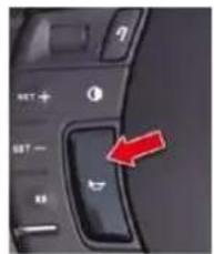
natural_image
Close-up of a computer keyboard interface with a red arrow pointing to the left button (no text or symbols visible)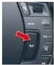
Press the left or right-hand part of the fixed centred controls steering wheel.
Use the horn moderately and only in the following cases:
- immediate danger,
- overtaking a cyclist or pedestrian
- when approaching an area where there is no visibility.
SAFETY
TYRE UNDER-INFLATION DETECTION
System which automatically checks the pressures of the tyres while driving.
Choice of detection
This function provides warning of tyres that are under-inflated or punctured.
Automatic detection
Sensors monitor the tyre pressures. In the event of an anomaly, a message will appear on the instrument panel screen.
Driver request detection
You can check the tyre pressures at any time.
Press on button A (CHECK); the information will be displayed on the instrument panel screen.
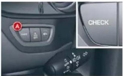
Tyres OK display
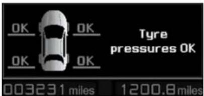
Press on button A (CHECK). The system indicates to you that the tyres are correctly inflated.
This information is only available on the request by the driver.
Under-inflated tyre
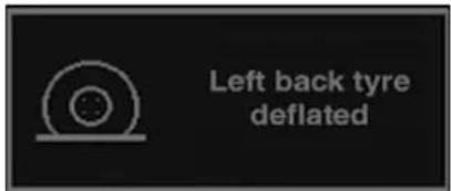
automatic detection
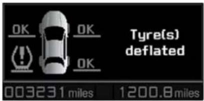
detection on request
Automatic detection:
A message indicates which tyre is under-inflated.
Driver request detection:
The vehicle outline indicates the under-inflated tyre(s).
The message is accompanied by lighting of the SERVICE warning lamp and an audible beep.
Check the tyre pressures as soon as possible.
SAFETY
Punctured tyre
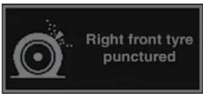
automatic detection
Wheel not monitored
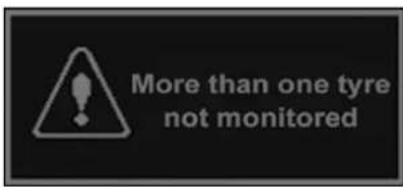
automatic detection
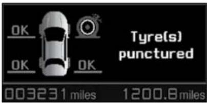
detection on request
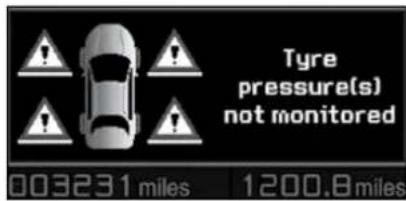
detection on request
Automatic detection:
A message indicates which tyre is punctured.
Automatic detection:
A message indicates to you which wheel is not monitored.
Driver request detection:
The vehicle outline indicates the punctured tyre(s).
The message is accompanied by lighting of the STOP warning lamp and an audible beep.
Driver request detection:
The vehicle outline indicates the wheel(s) which is/are not monitored.
The message is accompanied by lighting of the SERVICE warning lamp and an audible beep. Consult a CITROËN dealer.
If you have fitted wheels that are not equipped with tyre deflation detection (wheels with snow tyres, etc.), contact a CITROËN dealer.
The deflation detection system is a driving aid, but which does not absolve the driver from the need to be vigilant and responsible.
This system does not dispense with the requirement to check the tyres on a regular basis (see "Identifi cation markings") to ensure optimum vehicle behaviour and to avoid premature tyre wear under certain conditions (high load, high speed).
Do not forget to check the tyre pressure of the spare wheel.
Any repair or replacement of a tyre on a wheel that is equipped with a sensor must be carried out by a CITROËN dealer.
The system may suffer from temporary interference caused by radio transmissions on neighbouring frequencies.
SAFETY
Group of supplementary systems which help you to obtain optimum braking in complete safety in emergency situations:
- anti-lock braking system (ABS),
- electronic brake force distribution (EBFD),
- emergency braking assistance (EBA).
Anti-lock braking system and electronic brake force distribution
Linked systems which improve the stability and manoeuvrability of your vehicle when braking, in particular on poor or slippery surfaces.
Activation
The anti-lock braking system comes into operation automatically when there is a risk of wheel lock.
Normal operation of the ABS may make itself felt by slight vibration of the brake pedal.
When braking in an emergency, press very firmly without releasing the pressure.
Operating fault

If this warning lamp comes on, accompanied by an audible signal and a message on the instrument panel
screen, it indicates a malfunction of the anti-lock braking system which could result in loss of control of the vehicle when braking.

If this warning lamp comes on, together with the STOP and ABS warning lamps, accompanied by an audible
signal and a message on the instrument panel screen, it indicates a malfunction of the electronic brake force distribution which could result in loss of control of the vehicle when braking.
You MUST stop as soon as it is safe to do so.
In both cases, contact a CITROËN dealer.
When replacing wheels (tyres and rims), ensure that they conform to the manufacturer's recommendations.
Emergency braking assistance
System which, in an emergency, enables you to obtain the optimum braking pressure more quickly, thus reducing the stopping distance.
Activation
It is triggered by the speed at which the brake pedal is pressed.
The effect of this is a reduction in the resistance of the pedal and an increase in braking efficiency.
When braking in an emergency, press firmly without releasing the pressure.
SAFETY
Anti-skid regulation (ASR) and electronic stability programme (ESP)
The anti-skid regulation (also known as Traction Control) optimises traction to prevent skidding of the wheels, by acting on the brakes of the driving wheels and on the engine.
The electronic stability programme acts on the brake of one or more wheels and on the engine to keep the vehicle on the trajectory required by the driver, within the limits of the laws of physics.
Intelligent traction control (Snow Motion)
Your vehicle has an intelligent traction control system to help driving on snow: Snow Motion
This automatic system continuously checks for situations of diffi cult surface adhesion that could make it diffi cult to move off or make progress on deep fresh snow or compacted snow.
In these situations, the Snow Motion system takes over from the ASR system by optimising the amount of wheel slip to provide the best traction and trajectory control, even without snow tyres and with or without chains.
For vehicles with Hydractive III + suspension, manual adjustment of ground clearance to the intermediate position improves further the ability to make progress in deep snow (see the relevant paragraph).
In extremely severe conditions (snow on top of ice, sand, deep mud...), it can be useful to deactivate the ESP/ASR systems to allow a degree of wheel spin and so recover grip.
Activation
These systems are activated automatically each time the vehicle is started.
They come into operation in the event of a grip or trajectory problem.

This is indicated by flashing of this warning lamp on the instrument panel.
Deactivation
In exceptional conditions (starting a vehicle which is bogged down, stuck in snow, on soft ground...), it may be advisable to deactivate the ASR and ESP systems, so that the wheels can move freely and regain grip.
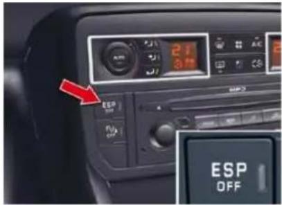
Press the "ESP OFF" button, located in the centre of the dashboard.

If this warning lamp comes on in the instrument panel and the indicator lamp on the button comes on, this indicates that the ASR and
ESP systems are deactivated.
SAFETY
Reactivation
These systems are reactivated automatically each time the ignition is switched back on or from 30 mph (50 km/h).
Press the "ESP OFF" button again to reactivate them manually.
Operating fault

If this warning lamp comes on, accompanied by an audible signal and a message on the instrument panel
screen, this indicates a malfunction of these systems.
Have the systems checked by a CITROËN dealer.
The ESP/ASR systems offer exceptional safety in normal driving, but this should not encourage the driver to take extra risks or drive at high speed.
The correct functioning of these systems depends on observation of the manufacturer's recommendations regarding the wheels (tyres and rims), the braking components, the electronic components and observation of the assembly and repair procedures used by CITROËN dealers.
After an impact, have these systems checked by a CITROËN dealer.
SEAT BELTS
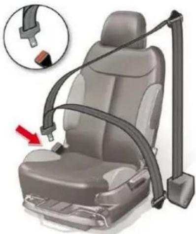
natural_image
Car seat assembly diagram showing seatbelt and seatbar with a red arrow indicating a specific component (no text or symbols present)Front seat belts
The front seat belts are fitted with a pretensioning system and force limiter. This system improves safety in the front seats in the event of a front impact.
Depending on the seriousness of the impact, the pretensioning system instantly tightens the seat belt against the body of the occupant.
The pretensioning seat belts are active when the ignition is on.
The force limiter reduces the pressure of the seat belt against the chest of the occupant, so increasing his protection.
Fastening
Pull the belt down in front of you in a steady movement, making sure that it does not become twisted.
Press the fastening into its buckle.
Check that it is properly secured and that the automatic locking mechanism operates correctly by pulling sharply on the belt strap.
The lap strap should be positioned as low down as possible in the lap and as tight as possible.
The diagonal strap should be positioned across the chest and away from the neck.
Each belt has a reel that adjusts its length automatically to the girth of the seat occupant.
SAFETY
Reactivation
These systems are reactivated automatically each time the ignition is switched back on or from 30 mph (50 km/h).
Press the "ESP OFF" button again to reactivate them manually.
Operating fault

If this warning lamp comes on, accompanied by an audible signal and a message on the instrument panel
screen, this indicates a malfunction of these systems.
Have the systems checked by a CITROËN dealer.
The ESP/ASR systems offer exceptional safety in normal driving, but this should not encourage the driver to take extra risks or drive at high speed.
The correct functioning of these systems depends on observation of the manufacturer's recommendations regarding the wheels (tyres and rims), the braking components, the electronic components and observation of the assembly and repair procedures used by CITROËN dealers.
After an impact, have these systems checked by a CITROËN dealer.
SEAT BELTS
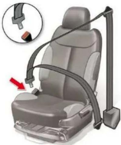
natural_image
Car seat assembly diagram showing seatbelt and seatbar with a red arrow indicating a specific component (no text or symbols present)Front seat belts
The front seat belts are fitted with a pretensioning system and force limiter. This system improves safety in the front seats in the event of a front impact.
Depending on the seriousness of the impact, the pretensioning system instantly tightens the seat belt against the body of the occupant.
The pretensioning seat belts are active when the ignition is on.
The force limiter reduces the pressure of the seat belt against the chest of the occupant, so increasing his protection.
Fastening
Pull the belt down in front of you in a steady movement, making sure that it does not become twisted.
Press the fastening into its buckle.
Check that it is properly secured and that the automatic locking mechanism operates correctly by pulling sharply on the belt strap.
The lap strap should be positioned as low down as possible in the lap and as tight as possible.
The diagonal strap should be positioned across the chest and away from the neck.
Each belt has a reel that adjusts its length automatically to the girth of the seat occupant.
SAFETY
Height adjustment
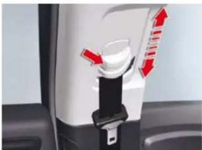
natural_image
Close-up of a white appliance with red directional arrows indicating movement or change (no text or symbols visible)When correctly adjusted, the seat belt shoulder strap falls over the middle of the shoulder.
To adjust the belt, squeeze the control and slide it in the direction required.
Unfastening
To unfasten the belt, press on the red button in the buckle.
The belt retracts automatically when not in use.
Rear seat belts
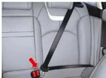
natural_image
Interior view of a car showing a black seatbelt buckle and red arrow pointing to the seat (no text or symbols visible)Each rear seat is fitted with a three-point inertia reel seat belt with force limiter.
Fastening
Pull the strap, then insert the tongue in the buckle.
Check that the seat belt is fastened correctly by pulling the strap.
Unfastening
Press the red button on the buckle.
SAFETY
The driver must ensure that passengers use the seat belts correctly and that they are all restrained securely before setting off.
Wherever you are seated in the vehicle, always fasten your seat belt, even for short journeys.
Do not invert the seat belt buckles as they will not fulfil their role fully.
The seat belts are fitted with an inertia reel permitting automatic adjustment of the length of the strap to your size. The seat belt is stored automatically when not in use.
Before and after use, ensure that the seat belt is reeled in correctly.
The lower part of the strap must be positioned as low as possible on the pelvis.
The upper part must be positioned in the hollow of the shoulder.
The inertia reels are fitted with an automatic locking device which comes into operation in the event of a collision, emergency braking or if the vehicle rolls over. You can release the device by pulling firmly on the strap and releasing it so that it re-winds slightly.
In order to be effective, a seat belt must:
- be tightened as close to the body as possible,
- be pulled in front of you with a smooth movement, checking that it does not twist,
- be used to restrain only one person,
- not bear any trace of cuts or fraying,
- not be converted or modified to avoid affecting its performance.
In accordance with current safety regulations, all repairs and checks must be carried out by a CITROËN dealer who guarantees that the work is carried out correctly.
Have your seat belts checked regularly by a CITROËN dealer and particularly if the straps show signs of damage.
Clean the seat belt straps with soapy water or a textile cleaning product, sold by CITROËN dealers.
After folding or moving a seat or rear bench seat, ensure that the seat belt is positioned and reeled in correctly.
Recommendations for children
Use a suitable child seat if the passenger is less than 12 years old or shorter than one and a half metres.
Never use the same seat belt to secure more than one person.
Never allow a child to travel on your lap.
In the event of an impact
Depending on the nature and seriousness of the impacts, the pre-tensioning device may be triggered before and independently of the airbags. Triggering of the pre-tensioners is accompanied by a slight discharge of harmless smoke and a noise, due to the activation of the pyrotechnic cartridge incorporated in the system.
In all cases, the airbag warning lamp comes on.
Following an impact, have the seat belts system checked, and if necessary replaced, by a CITROËN dealer.
SAFETY
AIRBAGS
System designed to maximise the safety of the occupants (with the exception of the rear centre passenger) in the event of violent collisions. It supplements the action of the force-limiting seat belts.
If a collision occurs, the electronic detectors record and analyse the front and side impacts sustained in the impact detection zones:
- in the case of a serious impact, the airbags are triggered instantly and protect the occupants of the vehicle (with the exception of the rear centre passenger); immediately after the impact, the airbags deflate rapidly so that they do not hinder visibility or the exit of the occupants,
- in the case of a minor or rear impact or in certain roll-over conditions, the airbags will not be triggered; the seat belt alone is sufficient to provide optimum protection in these situations.
The airbags do not operate when the ignition is switched off.
This equipment will only operate once. If a second impact occurs (during the same or a subsequent accident), the airbag will not operate.
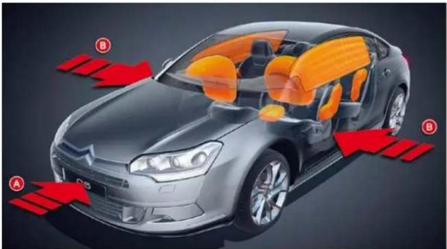
natural_image
Cutaway illustration of a car showing internal components with red arrows indicating flow or movement (no text or symbols)Impact detection zones
A. Front impact zone.
B. Side impact zone.
Triggering of the airbag(s) is accompanied by a slight emission of harmless smoke and a noise, due to the activation of the pyrotechnic cartridge incorporated in the system.
This smoke is not harmful, but sensitive individuals may experience slight irritation.
The noise of the detonation may result in a slight loss of hearing for a short time.
SAFETY
Front airbags
System which protects the head and chest of the driver and front passenger in the event of a front impact.
The driver's airbag is incorporated in the centre of the steering wheel; the front passenger's airbag is incorporated in the dashboard above the glove box.
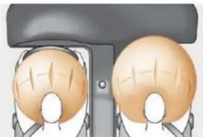
natural_image
Illustration of two identical figures with raised hands, viewed from the side (no text or symbols)Activation
The airbags are triggered simultaneously, unless the passenger's front airbag is deactivated, in the event of a serious front impact to all or part of the front impact zone A, in the longitudinal centreline of the vehicle on a horizontal plane and directed from the front to the rear of the vehicle.
The front airbag inflates between the front occupant of the vehicle and the dashboard to cushion their forward movement.
Deactivation
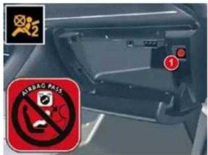
Only the front passenger's airbag can be deactivated:
with the ignition off, insert the key in the passenger airbag deactivation switch 1,
F turn it to the "OFF" position,
then, remove the key keeping the switch in this position.

This warning lamp comes on on the roof console display when the ignition is on and until the air bag is reactivated.
To guarantee the safety of your child, it is imperative that the passenger airbag is deactivated when you install a "rearwards-facing" child seat on the front passenger seat.
Otherwise, the child would risk being seriously injured or killed if the airbag were triggered.
Activation
When you remove the child seat, turn switch 1 to the "ON" position to reactivate the airbag and so guarantee the safety of your front passenger in the event of an impact.
Operating fault

If this symbol appears on the instrument panel screen, accompanied by an audible warning and a message,
contact a CITROEN dealer to have the system checked. The airbags may no longer be triggered in the event of a serious impact.

If this warning lamp fl ashes, contact a CITROËN dealer.
If both airbag warning lamps come on continuously, do not install a "rearwards-facing" child seat on the front passenger seat.
Have it checked by a CITROËN dealer.
SAFETY
Lateral airbags \*
System which protects the driver and front passenger in the event of a serious side impact in order to limit the risk of injury to the chest.
Each lateral airbag is incorporated in the front seat back frame, on the outer side.
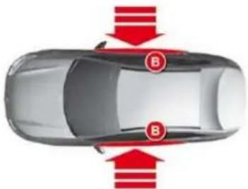
natural_image
Top-down view of a car with red arrows indicating downward motion or force, labeled 'B' (no text or symbols on the car itself)Activation
It is triggered unilaterally in the event of a serious side impact applied to all or part of the side impact zone B, perpendicular to the longitudinal centreline of the vehicle on a horizontal plane and directed from the outside towards the inside of the vehicle.
The side airbag inflates between the front occupant of the vehicle and the corresponding door trim pad.
Impact detection zones
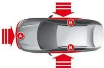
natural_image
Top-down view of a car with red directional arrows indicating traffic flow or movement (no text or symbols)A. Front impact zone.
B. Side impact zone.
Curtain airbags \*
System which protects the driver and passengers (with the exception of the rear centre passenger) in the event of a serious side impact in order to limit the risk of head injuries.
Each curtain airbag is incorporated in the pillars and the upper part of the passenger compartment.
Operation
It is triggered at the same time as the corresponding side airbag in the event of a serious side impact to all or part of the side impact zone B, perpendicular to the longitudinal centreline of the vehicle on a horizontal plane and directed from the outside towards the inside of the vehicle.
The curtain airbag inflates between the front or rear occupant of the vehicle and the windows.
In the event of a minor impact or bump on the side of the vehicle or if the vehicle rolls over, the airbag may not be triggered.
The airbag is not triggered in the event of a rear or front collision.
Operating fault

If this symbol appears on the instrument panel screen, accompanied by an audible signal and a message, con-
tact a CITROEN dealer to have the system checked. The airbags may no longer be triggered in the event of a serious impact.
SAFETY
For the airbags to be fully effective, observe the following safety rules:
Sit in a normal upright position.
Wear a correctly adjusted seat belt. Do not leave anything between the occupants and the airbags (a child, pet, object...). This could hamper the operation of the airbags or injure the occupants.
After an accident or if the vehicle has been stolen or broken into, have the airbag systems checked.
All work on the airbag system is strictly forbidden unless it is carried out by qualified personnel of the CITROËN dealer network.
Even if all of the precautions mentioned are observed, a risk of injury or of minor burns to the head, chest or arms when an airbag is triggered cannot be ruled out. The bag inflates almost instantly (within a few milliseconds) then deflates within the same time discharging the hot gas via openings provided for this purpose.
Front airbags
Do not drive holding the steering wheel by its spokes or resting your hands on the centre part of the wheel.
Passengers must not place their feet on the dashboard.
If possible, do not smoke as deployment of the airbags can cause burns or the risk of injury from a cigarette or pipe.
Never remove or pierce the steering wheel or hit it violently.
Lateral airbags
Use only approved covers on the seats. These will not hinder inflation of the lateral airbags. Consult a CITROËN dealer.
Do not fix or attach anything to the seat backs (clothing...). This could cause injury to the chest or arms if the lateral airbag is triggered.
Do not sit with the upper part of the body any nearer to the door than necessary.
Curtain airbags
Do not fix or attach anything to the roof. This could cause injury to the head if the curtain airbag is triggered.
Do not remove the grab handles installed on the roof, they play a part in securing the curtain airbags.
DRIVING
natural_image
Close-up of a car gear shift lever with a red arrow indicating the direction (no text or symbols visible)Mechanical device for immobilising the vehicle when stationary.
Application
√ Pull the parking brake lever up to immobilise your vehicle.
To facilitate the action on the lever, you are recommended to press the brake pedal at the same time.
Release
Press on the end of the lever whilst pulling it then lower it fully.

This warning lamp comes on if the parking brake is engaged or not fully released.
If the parking brake is released, the lighting of this warning lamp along with the STOP warning lamp indicates that the brake fluid level is low or a malfunction of the brake force distributor.
It is essential to stop the vehicle.
Consult a CITROËN dealer.
In all circumstances, as a precautionary measure, engage first gear.
On steep gradients, turn the steering wheel towards the pavement.
DRIVING
The electric parking brake combines 2 operational modes:
- AUTOMATIC
Automatic application when the engine stops and automatic release on use of the accelerator (automatic operation by default), MANUAL
Manual application/release of the parking brake is always possible by pulling control A while pressing the brake pedal.
Automatic operation
Application with the engine off
With the vehicle stationary, the parking brake is automatically applied when the engine is switched off.
The application of the parking brake is confirmed by:

- the lighting of the warning lamp on control A and on the instrument panel,
- the display of a message "hand-brake on" on the instrument panel screen.
The noise of operation will confirm to you the application/release of your electric parking brake.

Before leaving the vehicle, check that warning lamp P on the instrument panel is permanently lit.
Never leave a child alone inside the vehicle with the ignition on, as they could release the parking brake.
Application with the engine running
With the engine running and the vehicle stationary, in order to immobilise the vehicle you need to manually apply the parking brake by pulling on control A.
The application of the parking brake is confirmed by:

- the lighting of warning lamp P on control A and on the instrument panel,
- the display of a message "hand-brake on" on the instrument panel screen.
When the driver's door is opened, a beep is heard and a message displayed if the parking brake has not been applied.

Before leaving the vehicle, check that warning lamp P on the instrument panel is permanently lit.
DRIVING
Release
The electric parking brake releases automatically and progressively when you press the accelerator:
with a manual gearbox (first gear or reverse gear engaged), press down fully on the clutch pedal then press on the acce-lerator pedal and move off.
with an automatic gearbox, accelerate with the selector in position D, M or R.
Full release of the parking brake is confirmed by:

- the warning lamp P on control A and on the instrument panel going out,
- the display of a message "hand-brake off" on the instrument panel screen.
When stationary, with the engine running, do not press the accelerator pedal unnecessarily (particularly when starting the engine, including in neutral), as you may release the parking brake.
Activation/Deactivation of the automatic functions \*
Automatic application when switching off the engine and automatic release when moving off can be deactivated. The activation/deactivation is done in the instrument panel screen configuration menu. Select "Vehicle parameters/Comfort/Auto handbrake".

Deactivation of these functions is signalled by this warning lamp in the instrument panel.
With the automatic functions deactivated, the parking brake must be applied and released manually.
Deactivation of the automatic functions is recommended in very cold weather (freezing) and when towing (recovery, caravan...).
* Depending on country.
Manual operation
Manual application/release of the parking brake is always possible.
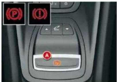
Application
With the vehicle stationary, to apply the parking brake whether the engine is running or off, pull on control A.
The application of the parking brake is confirmed by:

- the lighting of the warning lamp on control A and of warning lamp P on the instrument panel,
- the display of a message "hand-brake on" on the instrument panel screen.
When the driver's door is opened with the engine running, a beep is heard and a message displayed if the parking brake has not been applied.
IX
DRIVING
Release
The electric parking brake releases automatically and progressively when you press the accelerator:
with a manual gearbox (first gear or reverse gear engaged), press down fully on the clutch pedal then press on the acce-lerator pedal and move off.
with an automatic gearbox, accelerate with the selector in position D, M or R.
Full release of the parking brake is confirmed by:

- the warning lamp P on control A and on the instrument panel going out,
- the display of a message "hand-brake off" on the instrument panel screen.
When stationary, with the engine running, do not press the accelerator pedal unnecessarily (particularly when starting the engine, including in neutral), as you may release the parking brake.
Activation/Deactivation of the automatic functions \*
Automatic application when switching off the engine and automatic release when moving off can be deactivated. The activation/deactivation is done in the instrument panel screen configuration menu. Select "Vehicle parameters/Comfort/Auto handbrake".

Deactivation of these functions is signalled by this warning lamp in the instrument panel.
With the automatic functions deactivated, the parking brake must be applied and released manually.
Deactivation of the automatic functions is recommended in very cold weather (freezing) and when towing (recovery, caravan...).
* Depending on country.
Manual operation
Manual application/release of the parking brake is always possible.
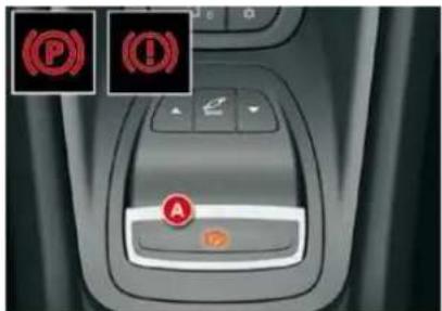
Application
With the vehicle stationary, to apply the parking brake whether the engine is running or off, pull on control A.
The application of the parking brake is confirmed by:

- the lighting of the warning lamp on control A and of warning lamp P on the instrument panel,
- the display of a message "hand-brake on" on the instrument panel screen.
When the driver's door is opened with the engine running, a beep is heard and a message displayed if the parking brake has not been applied.
IX
DRIVING
Release
With the ignition on or the engine running, to release the parking brake, press on the brake pedal, push then release control A.
The full application of the parking brake is confirmed by:

- the warning lamp on control A and the warning lamp P on the instrument panel going off,
- the display of a message "parking brake released" on the instrument panel screen.
If you push control A without pressing the brake pedal, the parking brake will not be released and the message "Apply foot on brake" will be displayed on the instrument panel.

When stationary, with the engine running, do not press the accelerator pedal unnecessarily, as you may release the parking brake.
Maximum application
If necessary, you can utilise maximum application of the parking brake. It is obtained by means of a long pull on control A, until you see the message "Max application of the handbrake" and a beep is heard.
Maximum application is essential:
- in the case of a vehicle towing a caravan or a trailer, if the automatic functions are activated but you are applying the parking brake manually,
- when the gradient you are parked on is variable in its effect (e.g. on a ferry, in a lorry, during towing).
- in the case of towing, a loaded vehicle or parking on a gradient, turn the front wheels towards the pavement and engage a gear when you park.
- after a maximum application, the release time will be longer.
Particular situations
In certain situations (starting the engine...), the parking brake can automatically alter its level of application. This is normal operation.
To advance your vehicle a few centimetres without starting the engine, but with the ignition on, press on the brake pedal and release the parking brake by pushing then releasing control A.
The full release of the parking brake is confirmed by the warning lamp P (red) on the instrument panel going off and the display of a message "handbrake off" on the instrument panel screen.
If the parking brake malfunctions while applied or if the battery is flat, an emergency release is still possible.
To ensure correct operation of the parking brake and therefore your safety, the number of successive application/release operations is limited to eight.
If this number is exceeded, you are warned by the message "Parking brake faulty" and a warning lamp fl ashes.
DRIVING
Dynamic emergency braking
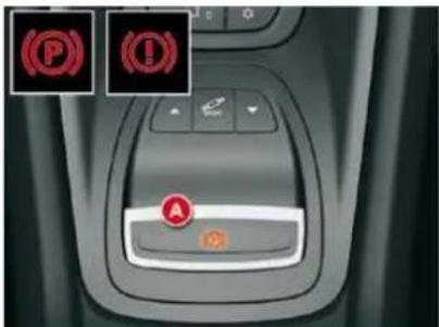
In the event of a failure of the vehicle's main braking system or in an exceptional situation (e.g. driver taken ill, under instruction, etc) pull and hold control A to stop the vehicle.
The electronic stability programme (ESP) provides stability during dynamic emergency braking.
If the dynamic emergency braking malfunctions, one of the following messages will be displayed on the instrument panel display:
- "Parking brake faulty".
- "Parking brake control faulty".

If a failure of the ESP system is signalled by the lighting of this warning lamp, then braking stability is not
guaranteed. In this event, stability must be assured by the driver by repeating alternate "pull release" actions on control A.

The dynamic emergency braking must only be used in exceptional circumstances.
Emergency parking brake release
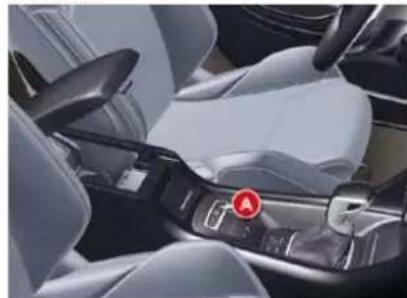
natural_image
Interior view of a car headrest with silver seat, black arm strap, and white interior (no visible text or symbols)In the event of the electric parking brake failing to release, an emergency device can be used to release the parking brake manually, provided that it is possible to immobilise the vehicle while the procedure is carried out.
If you can start the vehicle: with the engine running, immobilise the vehicle by applying the foot brake while the operation is being carried out.
If you are unable to start the vehicle (fi at battery for example): do not use this device and contact a CITROËN dealer. However, if you are obliged to proceed, fi rst immobilise your vehicle securely and then follow the instructions below.
DRIVING
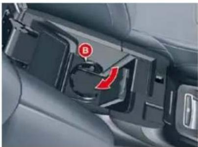
natural_image
Close-up of a car interior showing a black plastic door with a red circular indicator labeled 'B' and a red curved arrow pointing to the door (no text or symbols beyond the label)Immobilise the vehicle by placing a chock at the front or at the rear of one of the rear wheels.
Open the lower compartment of the centre armrest by pulling it.
Ensure that the cup holder B is folded away.
Remove the rubber mat covering the base of the armrest.
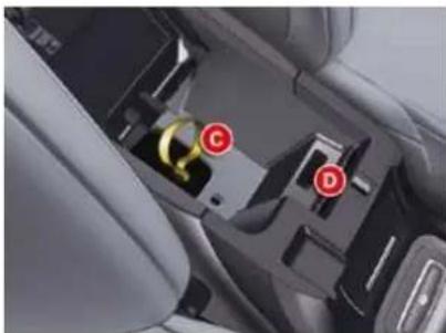
natural_image
Interior view of a car's rear seat and dashboard compartment showing labeled buttons (C, D) and a yellow hammer symbol on the door panel (no readable text or symbols beyond labels)Release the strap from its location C.
Pull the strap to release the brake. A loud knock confi rms the release of the brake.
Take care to put the strap back in its location C correctly. Otherwise, it will no longer be possible to apply the brake. Consult a CITROEN dealer.
Put the rubber mat back in place on the base of the armrest.
!
This strap does not permit application of the parking brake.
To re-engage the electric parking brake (after rectifying the malfunction or battery failure), give a long pull on the control A until the parking brake warning lamp (!) fl ashes on the instrument panel then give a second long pull until this warning lamp is lit permanently.
The time required for the subsequent application may be longer than during normal operation.
It is essential that the ignition is not switched on until the parking brake has re-engaged (fl ashing of the warning lamp (!) on the instrument panel then warning lamp lit permanently) to avoid damage to the parking brake.
Take care not to allow moisture or dust in the proximity of the diagnostic socket D which is essential for the maintenance of your vehicle.
DRIVING
Operating anomalies

If any of these instances arises, contact a CITROËN dealer as soon as possible.
| SITUATION | CONSEQUENCES | |
| 1 | Electric parking brake fault and display of message " Parking brake faulty " and the following warning lamps: SERVICE SERVICE | If the electric parking brake fault warning lamp and the service warning lamp light up, position the vehicle in a safe location (on fl at ground, with a gear engaged). |
| 2 | Display of the messages " Parking brake faulty" and "Anti roll-back fault" and of the following warning lamps: SERVICE SERVICE | - The automatic functions are deactivated.- The hill start assist is unavailable.- The electric parking brake is only available manually. |
| 3 | Display of messages " Parking brake faulty and "Anti roll-back fault" and of the following warning lamp:SERVICE | - Manual release of the electric parking brake is unavailable.- The hill start assist is unavailable.- The automatic functions and manual application are still available. |
DRIVING
| SITUATION | CONSEQUENCES | |
| 4 | Display of messages " Parking brake faulty and "Anti roll-back fault" and of the following warning lamps:   fl as fl as  | - The automatic functions are deactivated.- The hill start assist is unavailable.To apply the electric parking brake:Immobilise the vehicle and switch off the ignitionPull the control lever for at least 5 seconds or until maximum application.Switch on the ignition and check that the electric parking brake warning lamps are on.- Application may take longer than in normal operation.If warning lamp (!) fl ashes or if the warning lamps do not come on when the ignition is switched on, this method does not work.Have it checked by a CITROËN dealer.To release the electric parking brake:Switch on the ignition.Push the control lever and hold it for approximately 3 seconds. |
| 5 | Display of message " Parking brake control faulty – automatic mode activated " and the following warning lamps: fl as fl as  | - Only the functions for automatic application on switching off the engine and automatic release on acceleration are available.- Manual application/release of the electric parking brake and dynamic emergency braking are unavailable. |
| 6 | Display of message " Parking brake faulty " and of the following warning lamp: ing ing | - Application of the parking brake is not guaranteed.- The parking brake is temporarily unavailable.It this situation arises:Wait approximately 3 minutes.After 3 minutes, if the warning lamp is still flashing, try to reini-tialise the parking brake, either by pushing and releasing the control A while pressing the brake pedal or by means of a long pull on control A . |
| 7 | Battery fault | - Lighting of the battery warning lamp makes it essential to stop the vehicle as soon as traffi c allows. Stop and immobilise your vehicle.- Apply the electric parking brake before switching off the engine. |
DRIVING
HILL START ASSIST
System which keeps your vehicle immobilised temporarily (approximately 2 seconds) when starting on a gradient, the time it takes to move your foot from the brake pedal to the accelerator pedal.
This function is only active when:
- the vehicle is completely stationary, with your foot on the brake pedal,
- in certain conditions on a gradient,
- with the driver's door closed.
The hill start assist function cannot be deactivated.
Operation
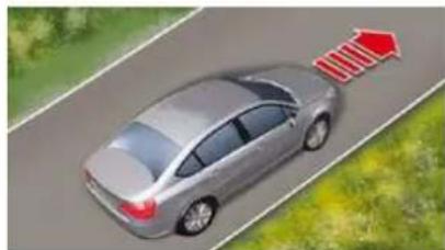
natural_image
Illustration of a silver sedan driving on a road with a red arrow pointing upward (no text or symbols)On an ascending gradient, with the vehicle stationary, the vehicle is held for a brief moment when you release the brake pedal:
- provided you are in first gear or neutral on a manual gearbox,
- provided you are in D or M on an automatic gearbox.
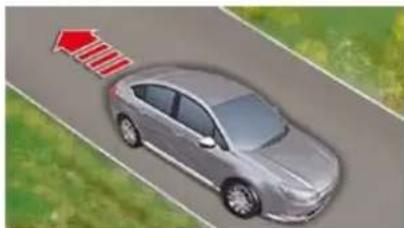
natural_image
Illustration of a silver sedan driving on a road with a red arrow indicating speed (no text or symbols)On a descending gradient, with the vehicle stationary and reverse gear engaged, the vehicle is held for a brief moment when you release the brake pedal.
Do not exit the vehicle while it is being held in the hill start assist phase.
If you need to exit the vehicle with the engine running, manually apply the parking brake and ensure that the parking brake warning lamp (on the instrument panel) and the warning lamp P (on the control lever A) are permanently on.
DRIVING
5-SPEED MANUAL GEARI
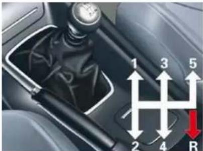
natural_image
Close-up of a car gear shift lever mechanism with numbered arrows indicating direction (no text or symbols)Starting the vehicle
Check that the gear lever is in neutral.
Do not touch the accelerator.
For Diesel engines: turn the key to position M and wait until the pre-heating warning lamp switches off if it has come on.
Operate the starter, turning the key until the engine starts (no more than ten seconds).
In temperatures lower than 0^ C, declutch while operating the starter to facilitate starting.
Engaging reverse gear
Push the gear lever to the right then rearwards.
Only engage reverse gear when the vehicle is stationary with the engine at idle.
Engaging reverse gear
F Raise the ring under the knob (indicated by the arrow) and push the gear lever to the left then forwards.
Only engage reverse gear when the vehicle is stationary with the engine at idle.
As a safety precaution and to facilitate starting of the engine:
- always select neutral,
- press the clutch pedal.
- always select neutral, - press the clutch pedal.
DRIVING
GEAR ECONOMY INDICATOR
System which reduces fuel consumption by advising the driver to change up on vehicles fitted with a manual gearbox.
Operation
The system intervenes only when driving economically.
Depending on the driving situation and your vehicle's equipment, the system may advise you to skip one or more gears. You can follow this instruction without engaging the intermediate gears.
The gear engagement recommendations must not be considered compulsory. In fact, the configuration of the road, the amount of traffic and safety remain determining factors when choosing the best gear. Therefore, the driver remains responsible for deciding whether or not to follow the advice given by the system.
This function cannot be deactivated.
Example:
- You are in third gear.
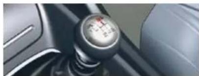
natural_image
Close-up of a car gear shift knob showing speed and angle (no text or symbols visible)- You press the accelerator pedal moderately.
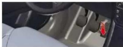
natural_image
Close-up of a car interior showing the wheel, dashboard, and seatbelt (no visible text or symbols)- The system may suggest that you engage a higher gear, if appropriate.
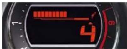
The information appears in the instrument panel screen in the form of an arrow accompanied by the suggested gear.
In the case of driving which makes particular demands on the performance of the engine (firm pressure on the accelerator pedal, for example, when overtaking...), the system will not recommend a gear change.
The system never suggests:
- engaging fi rst gear,
- engaging reverse gear,
- engaging a lower gear.
DRIVING
AUTOMATIC GEARBOX
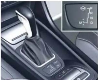
natural_image
Interior view of a car showing a car's left-hand side with a handwheel and control buttons, alongside an inset diagram of the right-hand side with symbols (P, R, N, M) and directional arrows.Automatic gearbox which offers a choice between the comfort of fully automatic operation, enhanced by the sport and snow programmes, or manual gear changing.
Four driving modes are provided:
- automatic operation for electronic control of the gears by the gearbox,
- the SPORT programme for a more dynamic driving style,
- the SNOW programme to improve driving when the grip is poor,
- manual operation for sequential changing of the gears by the driver.
Mode selection Displays on the instrument panel
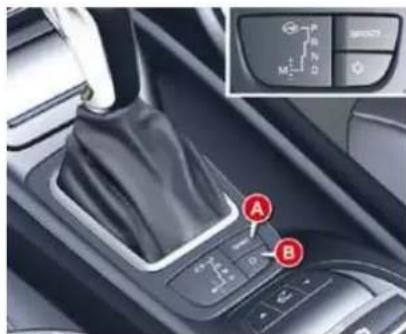
automatic mode: gear lever in position D,
sequential mode: gear lever in position M,
SPORT mode: gear lever in position D and button A pressed,
SNOW mode: gear lever in position D and button B pressed.
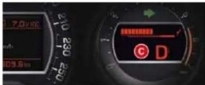
The position of the gear lever and the driving mode are displayed on the instrument panel dial C.
A position grille associated with the gear lever allows you to view the selected position.

For safety:
- position P can be disengaged only if you press the brake pedal,
- when a door is opened, an audible signal is heard if the gear lever is not in position P,
- always make sure that the gear lever is in position P before you leave your vehicle.
If the gearbox is in position P but the position of the gear lever is different, reposition the gear lever on P so that you can start the vehicle.
DRIVING
Moving off
To start the engine, the gear lever must be in position P or N.
Operate the starter.
When the engine is running, place the gear lever on R, D or M as required.
Check, in the instrument panel, the position engaged.
Release the brake pedal and accelerate.
To avoid incoherence between the position of the gear lever and the actual position of the gearbox, always exit from position P with the ignition on and brake pedal applied.
Otherwise, when the ignition is on or the engine is running:
reposition the gear lever in position P.
put your foot on the brake pedal and then select the gear you want.
Park

This position of the gear lever is used to prevent the vehicle from moving when you are stationary.
To select position P, move the gear lever back to the highest position (towards R), then push it forwards and then to the left.
To exit position P, move the gear lever to the right and then to the position you want.
Only engage this position when the vehicle is completely stationary. In this position, the front wheels are locked. Make sure that the gear lever is correctly positioned.
Reverse gear

Only engage this position when the vehicle is stationary. To prevent snatching, do not accelerate too soon after selection.
Neutral

Never select position N if the vehicle is moving.
Never select positions P or R if the vehicle is not stationary. If, while the vehicle is moving, position N is engaged inadvertently, allow the engine to idle before engaging position D or M.
DRIVING
Automatic operation
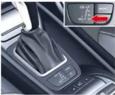
natural_image
Interior view of a car gear shift lever with control panel and infotainment switch (no readable text or symbols)Move the gear lever to position D.
The gearbox constantly selects the gear that is best suited to the following parameters:
- driving style,
- road profi le
- vehicle load.
The gearbox operates without requiring any intervention on your part.
For certain manoeuvres (for example overtaking), you can obtain maximum acceleration by pressing the accelerator pedal hard down past the point of resistance, which then produces an automatic change down to a lower gear.
When braking, the gearbox may change down automatically in order to provide effective engine braking. If you lift your foot off the accelerator abruptly, the gearbox will not engage a higher gear.
Manual operation
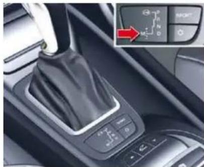
natural_image
Interior view of a car gear shift lever with control panel and directional arrow indicator (no text or symbols on the main component)Position of the gear lever for manual gear changing.
Move the gear lever to position M.
" Push the gear lever towards the " + " sign to change up a gear.
Pull the gear lever towards the " - " sign to change down a gear.
- If the vehicle stops or reduces speed (for example when approaching a stop sign), the gearbox changes down automatically to first gear.
- In sequential mode, it is not necessary to release the accelerator during gear changes.
- A request to change gear is accepted only if the engine speed permits it.
- The SPORT and SNOW modes do not operate in sequential mode.
DRIVING
SPORT and SNOW programmes
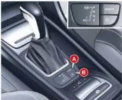
These two special programmes supplement the automatic operation in very particular conditions of use.
SNOW programme " \* "
With the gear lever in position D and the engine running, press button B.
The gearbox adapts to driving on slippery roads.
This programme makes moving off easier and improves traction in conditions of poor grip.

* appears on the instrument panel.
Return to automatic operation
At any time, press the button selected again to exit from the programme engaged and return to auto-adaptive mode.
A strong snatch may be felt when selecting R for reverse gear.
In the event of a malfunction, the gearbox is blocked in one gear; do not exceed a speed of 62 mph (100 km/h).
Do not turn off the engine while the gear selector is in position D or R.
Never press the accelerator and brake pedals simultaneously.
Braking and acceleration should be done with the right foot only. Pressing both pedals simultaneously may damage the gearbox.
Consult a CITROËN dealer.
SPORT programme "S"

With the gear lever in position D and the engine running, press button A.
The gearbox automatically favours a dynamic driving style.
S appears on the instrument panel.
DRIVING
FIXED CENTRED CONTROLS STEERING WHEEL
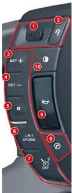
| 1 | Rotation | - Scroll the various pages of information on the instrument panel screen. - Move through the various menus on the instrument panel screen. - Increase/decrease values. |
| Short press | - Open the menu on the instrument panel screen (only when stationary). - Select and confi rm information | |
| Long press | Trip computer zero reset (if the trip computer page is displayed). | |
| 2 | Short press | - Cancel the current operation. - Return to the previous screen on the instrument panel screen. |
| Long press | Return to the initial page on the instrument panel screen. | |
| 3 | Short press | Increase the speed in steps of 1 mph (1 km/h)/storing the speed. |
| Maintained press | Increase the speed in steps of 5 mph (5 km/h). | |
| 4 | Short press | Decrease the speed in steps of 1 mph (1 km/h)/storing the speed. |
| Maintained press | Decrease the speed in steps of 5 mph (5 km/h). | |
| 5 | Short press | Suspend or resume cruise control/speed limiter (depending on the mode selected). |
| 6 | Short press | Select cruise control or speed limiter mode (the cycle on this button will always begin with selection of the speed limiter). |
| 7 | Short press | Deactivate cruise control/speed limiter. |
| 8 | Short press | - Pick up an incoming call. - Hang up the current call. - Open the telephone short-cut menu. - Confi rm on the list and the telephone menu. |
| Long press | Refuse an incoming call. | |
| 9 | Short press/Long press Horn. | |
| 10 | Short press | Activate/deactivate Black Panel mode (night driving). |
| 11 | Short press | Activate the voice command. |
| Long press | Navigation instruction repeat. | |
DRIVING
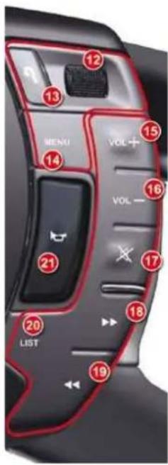
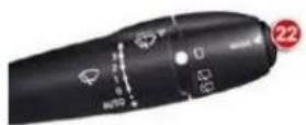
| 12 | Rotation | - Radio source: Scroll the pre-set stations.- CD/MP3 CD/CD changer/jukebox source: Scroll the CDs or directories.- On the multifunction screen menus: Movement and increase/decrease. |
| Short press | - On the multifunction screen menus: confi rm.- Open the short-cut menus (depending on the multifunction screen page). | |
| Long press | Open the multifunction screen main menu. | |
| 13 | Short press | Cancel the current operation and return to the previous page on the multifunction screen.When an incoming telephone call is received: Refuse the call. |
| Long press | Return to the initial page on the multifunction screen. | |
| 14 | Short press | Access to the multifunction screen general menu. |
| 15 | Short press/Maintained press | Volume increase. |
| 16 | Short press/Maintained press | Volume decrease. |
| 17 | Short press | - First press: mute.- Second press: restore sound. |
| 18 | Short press | - Radio source: Automatic search of higher frequencies.- CD/MP3 CD/CD changer/jukebox source: Search for the next track. |
| Maintained press | - CD/MP3 CD/CD changer/jukebox source: Fast forward play. | |
| 19 | Short press | - Radio source: Automatic search of lower frequencies.- CD/MP3 CD/CD changer/jukebox source: Search for the previous track. |
| Maintained press | CD/MP3 CD/CD changer/jukebox source: Fast backwards. | |
| 20 | Short press | - Radio source: display the list of radio stations available.- CD/MP3 CD and CD changer source: display the list of CD tracks and directories.- Jukebox source: display the list of albums. |
| Long press | Update the list of radio stations. | |
| 21 | Short press/Long press | Horn. |
| 22 | Short press | MODE: selection of the type of information presented on the multifunction screen. |
DRIVING
SPEED LIMITER
System which prevents the vehicle from exceeding the speed programmed by the driver.
When the limit speed is reached, the accelerator pedal no longer has any effect.
The speed limiter is switched on manually: a speed of at least 20 mph (approx. 30 km/h) must be programmed.
The speed limiter can in no way replace respect for speed limits or vigilance and responsibility on the part of the driver.
Steering mounted controls
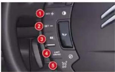
The speed limiter switches are located on the left-hand side of the steering wheel.
Displays on the instrument panel

The speed limiter information is displayed in zone A of the instrument panel.
Successive presses will modify the maximum speed in steps of 1 mph and a continuous press in steps of 5 mph.
Programming
Press on button 4 to select speed limiter mode "LIMIT".
The selection is confirmed by the display of the function in zone A of the instrument panel.
When the function is selected, the last memorised speed and the information "PAUSE" are displayed. With the engine running, you can adjust the memorised maximum speed, displayed in zone A, by pressing on:
Button 1 to increase the memorised maximum speed.
√ Button 2 to decrease the memorised maximum speed.
Activation
Press on button 3 when the desired maximum speed is displayed.
The information "ON" then appears in zone A.
DRIVING
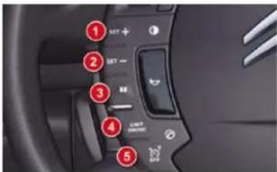
Suspension/Resumption
Press on button 3.
This action causes the information "PAUSE" to appear in zone A of the instrument panel.
This action does not cancel the memorised maximum speed which remains displayed in zone A of the instrument panel.
Overriding the programmed speed
The accelerator pedal has an end-of-travel switch. In order to exceed the memorised maximum speed at any time, you can press the pedal all the way down. While the speed is being exceeded, the speed displayed in zone A will flash. You have only to release the accelerator pedal to return below the maximum speed, to restore the function.
The speed will also fl ash if the speed limiter is not able to prevent the vehicle from exceeding the programmed speed (e.g. on a steep descent or under excessive acceleration).
To reactivate the speed limiter, release the accelerator to slow to a speed lower than the programmed speed.
Return to normal driving
Either press on button 5.
Or select the speed limiter function.
Or stop the engine.
Operating fault
If there is a malfunction, a message is displayed accompanied by an audible signal and lighting of the SERVICE warning lamp.
Have it checked by a CITROËN dealer.
In the event of a steep descent or under excessive acceleration, the speed limiter (which does not act on the brakes) may not be able to prevent the vehicle from exceeding the programmed speed.
Use of a floor mat other than that recommended by CITROËN may affect the normal operation of the accelerator pedal and hamper the operation of the speed limiter.
Floor mats approved by CITROËN are fi tted with a 3rd fi xing located in the pedal area to avoid any risk of interference with the pedals.
DRIVING
CRUISE CONTROL
System which automatically maintains the vehicle speed programmed by the driver, without any action on the accelerator pedal.
The cruise control is switched on manually: the vehicle speed must be at least 25 mph (40 km/h) and you must be in at least:
- 4th gear for manual gearboxes,
- 2nd gear for automatic gearboxes.
Displays on the instrument panel
The programmed information is grouped together in zone A of the instrument panel.
Steering mounted controls
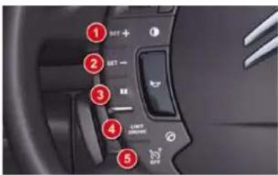
The cruise control switches are located on the left-hand side of the steering wheel.
Programming
Press button 4 to select cruise control mode "CRUISE".
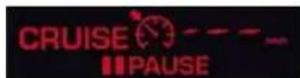
The selection is confirmed by the display of the function in zone A of the instrument panel.
When the function is selected, no cruising speed has yet been memorised.
Once the desired speed has been reached using the accelerator, press button 1 or button 2. The cruising speed is then memorised and cruise control is activated. The cruising speed is displayed in zone A of the instrument panel, and "ON" is displayed.
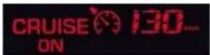
You can then release the accelerator pedal. The vehicle will automatically keep to the speed chosen.
The vehicle speed may vary slightly from that memorised.
If during cruise control the system cannot keep to the cruise speed (e.g. on a steep descent), then the speed flakes. If necessary, brake to curb your speed.
Adjustment of the memorised speed while cruise control is in operation
You can adjust the memorised speed, displayed in zone A, by pressing:
- Button 1 to increase the speed. - Button 2 to reduce the speed.
Successive presses will modify the cruise speed in steps of 1 mph and a continuous press in steps of 5 mph.
DRIVING
Overriding the programmed speed
While cruise control is in operation, it is always possible to go above the programmed speed simply by pressing the accelerator pedal (for example to overtake another vehicle).
The speed displayed in zone A fl ashes.
You only have to release the accelerator pedal to return to the programmed speed.
Suspension/Resumption
Either by pressing the brake pedal or the clutch pedal.
Or by pressing button 3.
Or by the ESP or ASR systems being active.
For vehicles with a manual gearbox, cruise control is deactivated if the gear lever is in neutral.
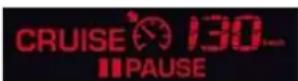
"PAUSE" will be displayed in zone A of the instrument panel.
These actions do not cancel the cruising speed which remains displayed on the instrument panel.
Reactivation
- By recalling the memorised speed
After deactivation, press button 3. Your vehicle automatically returns to the memorised cruising speed. The memorised speed and "ON" are displayed in zone A.
If the memorised cruising speed is higher than the current speed, the vehicle will accelerate strongly to reach the current speed.
- By selecting the current speed
Press button 1 or 2 once the desired speed has been reached.
The new speed and "ON" will appear in zone A.
Return to normal driving
Either press on button 5.
Or select the cruise control function.
Or stop the engine.
The speed that was chosen is no longer memorised.
Operating fault
If there is a malfunction, a message is displayed accompanied by an audible signal and lighting of the SERVICE warning lamp.
Have it checked by a CITROËN dealer.
Cruise control must only be used where the traffic conditions permit driving at a constant speed.
Do not use it on congested roads or when the weather or the road conditions are poor.
The driver must remain attentive and in complete control of the vehicle.
You are recommended to keep your feet within range of the pedals.
IX
DRIVING
LANE DEPARTURE WARNING SYSTEM
System which detects the involuntary crossing of longitudinal traffic lane markings on the ground (solid or broken line).
Sensors, fitted below the front bumper, trigger a warning if the vehicle drifts over a lane marking (speed higher than 50 mph (80 km/h)).
This system is particularly useful on motorways and main roads.
The lane departure warning system cannot, in any circumstances, replace the need for vigilance and responsibility on the part of the driver.
Activation
Press button A, the indicator lamp comes on.
Deactivation
Press button A again, the indicator lamp switches off.
The status of the system remains in the memory when the ignition is switched off.
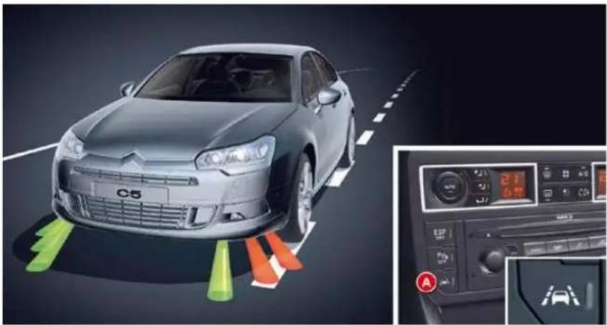
natural_image
Exterior view of a C5 car with colored traffic cone indicators and dashboard display (no readable text or symbols)Detection
You are warned by the vibration of the driver's seat cushion:
- on the right-hand side, if the marking on the ground has been crossed on the right,
- on the left-hand side, if the marking on the ground has been crossed on the left.
No warning is transmitted while the direction indicator is active and for approximately 20 seconds after the direction indicator is switched off.
A warning may be transmitted if a direction marking (e.g. arrow) or non-standard marking (e.g. graffi ti) is crossed.
Operating fault
In the event of a malfunction, the service warning lamp comes on, accompanied by an audible signal and a message on the multifunction screen.
Consult a CITROËN dealer.
The detection may be impeded:
- if the sensors are dirty (mud, snow...),
- if the markings on the ground are worn.
- if there is little contrast between the markings on the ground and the road surface.
PARKING SPACE SENSOR
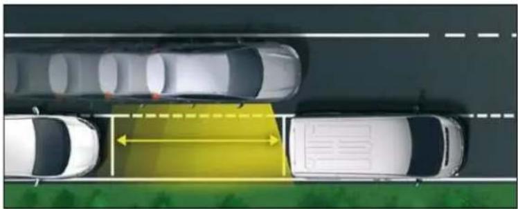
natural_image
Top-down view of a multi-lane road with cars and a yellow traffic sign indicating lane separation (no text or symbols)System which measures the parking space available between two vehicles or obstacles. It measures the size of the space and gives you information on:
- the possibility of fitting into a free space, depending on the dimensions of your vehicle and the distances necessary for your manoeuvring,
- the level of diffi culty of the manoeuvre to be performed.
The system does not measure spaces which are clearly much smaller or larger than the size of the vehicle.
Displays on the instrument panel
The parking space sensor function warning lamp can have three different states:
- off: the function is not selected,
- on fixed: the function is selected but the conditions for measuring are not yet met (direction indicator not operating, speed too high) or the measurement is terminated.
- fl ashing: measurement is in progress or the message is being displayed.
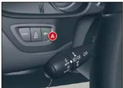
natural_image
Interior view of a car showing the left-hand side with a black control knob and a green play button (no text or symbols visible)You can select the "parking space sensor" function by pressing button A. The fixed lighting of the warning lamp indicates that the function is selected.
During the measurement, the message "Measurement in progress - Vmax 20 km/h (12 mph)" is displayed on the instrument panel screen.
DRIVING
Operation
You have identified a parking space:
Press button A to select the function.
Activate the direction indicator on the side where the space is to be measured.
During measurement, go forward the length of the space, at a speed less than 12 mph (approx. 20 km/h), to prepare for your manoeuvre.
The system then measures the size of the space.
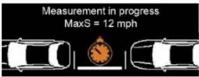
The system informs you of the level of diffi culty of the manoeuvre via a message on the instrument panel screen accompanied by a gong.
Depending on the message is-
sued by the system, you may or
may not be able to perform the
manoeuvre.
The function displays the following types of message:
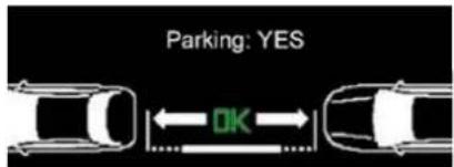
Parking YES
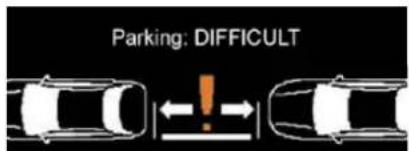
Parking diffi cult
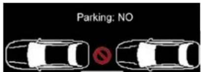
Parking NO
The function deselects itself automatically:
- when you engage reverse gear,
- when you switch off the ignition,
- if measurement is not requested,
- within five minutes of selection of the function.
- if the vehicle speed exceeds the threshold of 45 mph (approx. 70 km/h) for one minute.
If the lateral distance between your vehicle and the parking space is too large, the system may not be able to measure the space.
The function remains available after each measurement and thus can measure more than one space during your search.
In bad weather conditions or in winter, make sure that the sensors are not covered by dirt, or by ice or snow.
The parking space sensor function deactivates the front parking assistance during space measurement when you are in forward gear.
If there is a malfunction, have the system checked by a CITROËN dealer.
DRIVING
VISUAL AND AUDIBLE FRONT AND/OR REAR PARKING SENSORS
System consisting of proximity sensors, installed in the front and/or rear bumper.
It detects any obstacle (person, vehicle, tree, barrier...) located in front of or behind the vehicle, however, it will not be able to detect obstacles located immediately below the bumper.
An object, such as a stake, a road-works cone or any other similar object may be detected at the start of the manoeuvre but may no longer be detected when the vehicle moves nearer to it.

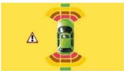
natural_image
Top-down view of a car with warning sign and sensor waves on yellow background (no text or symbols)The parking assistance is switched on :
- by engaging reverse gear,
- at a speed below 6 mph (10 km/h) in forward gear.
This is accompanied by an audible signal and/or displaying of the vehicle on the multifunction screen.
The proximity information is indicated by:
- an audible signal which becomes more rapid as the vehicle approaches the obstacle,
- a diagram on the multifunction display, with blocks which move closer to the vehicle.
The obstacle is located in relation to the emission of the audible signal by the speakers; front or rear and right or left.
When the distance between the vehicle and the obstacle is less than approximately thirty centimetres, the audible signal becomes continuous and/or the "Danger" symbol appears, depending on the multifunction screen version.
The parking assistance system cannot, in any circumstances, replace the need for vigilance and responsibility on the part of the driver.
Deactivation
Press button A, the warning lamp comes on, the system is fully deactivated.
The system will be deactivated automatically when a trailer is being towed or when a bicycle carrier is fitted (vehicle fitted with a towbar or bicycle carrier recommended by CITROËN).
The parking assistance is switched off :
- when you exit reverse gear,
- when the speed is higher than 6 mph (10 km/h) in forward gear,
- when the vehicle has been stationary for more than three seconds in forward gear.
DRIVING
Reactivation
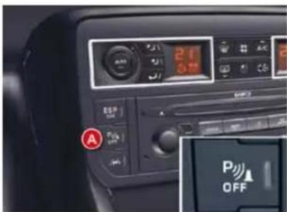
Press button A again, the warning lamp switches off, the system is reactivated.
In bad weather or in winter, ensure that the sensors are not covered with mud, ice or snow. When reverse gear is engaged, an audible signal (long beep) indicates that the sensors may be dirty.
When the speed of the vehicle is below about 6 mph (10 km/h), some sources of noise (motorcycle, lorry, pneumatic drill, ...) may trigger the audible parking sensor signals.
"HYDRACTIVE III +" ELECTRONIC SUSPENSION
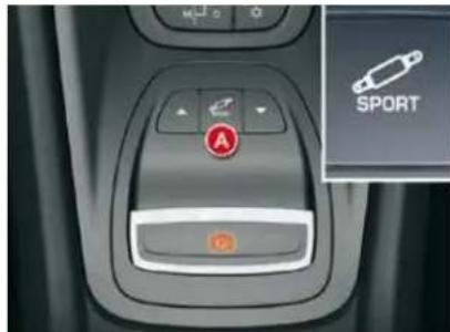
The suspension automatically and instantly adjusts to different driving styles and to the profile of the road, providing the best compromise between occupant comfort and vehicle road holding.
The system alternates between soft and firm suspension settings, maximising comfort at the same time as constantly ensuring the highest level of safety. It also automatically corrects ride height, according to the vehicle load and driving conditions.
In addition, the "Hydractive III +" system allows you to choose between two modes of suspension.
A change of suspension mode can be made either when the vehicle is moving or when stationary, by pressing button A.
Display on the instrument panel
The suspension mode selected is displayed on the instrument panel screen.
Normal mode
This mode favours soft damping for maximum comfort.
If the speed authorised for a particular position is exceed-
ed, the vehicle reverts automatically to the normal road position.
SPORT mode
This mode favours dynamic driving.
The warning lamp on button A comes on in addition to the message on the instru-
ment panel screen.
SPORT mode is retained when you switch off the engine.
DRIVING
Reactivation
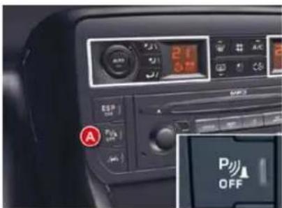
Press button A again, the warning lamp switches off, the system is reactivated.
In bad weather or in winter, ensure that the sensors are not covered with mud, ice or snow. When reverse gear is engaged, an audible signal (long beep) indicates that the sensors may be dirty.
When the speed of the vehicle is below about 6 mph (10 km/h), some sources of noise (motorcycle, lorry, pneumatic drill, ...) may trigger the audible parking sensor signals.
"HYDRACTIVE III +" ELECTRONIC SUSPENSION
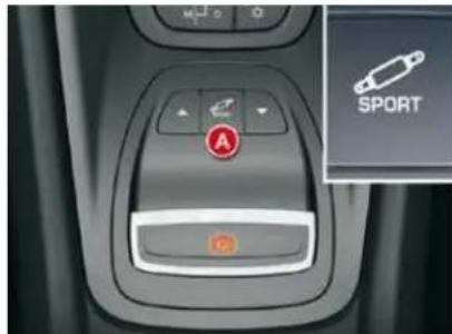
The suspension automatically and instantly adjusts to different driving styles and to the profile of the road, providing the best compromise between occupant comfort and vehicle road holding.
The system alternates between soft and firm suspension settings, maximising comfort at the same time as constantly ensuring the highest level of safety. It also automatically corrects ride height, according to the vehicle load and driving conditions.
In addition, the "Hydractive III +" system allows you to choose between two modes of suspension.
A change of suspension mode can be made either when the vehicle is moving or when stationary, by pressing button A.
Display on the instrument panel
The suspension mode selected is displayed on the instrument panel screen.
Normal mode
This mode favours soft damping for maximum comfort.
If the speed authorised for a particular position is exceed-
ed, the vehicle reverts automatically to the normal road position.
SPORT mode
This mode favours dynamic driving.
The warning lamp on button A comes on in addition to the message on the instru-
ment panel screen.
SPORT mode is retained when you switch off the engine.
DRIVING
Vehicle positions
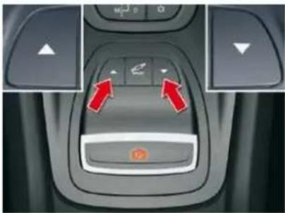
natural_image
Interior view of a car dashboard with control buttons and directional arrows (no text or symbols)Position changes may only be made when the engine is running.
The adjustable ground clearance meets all types of situation. Apart from a few specific situations, the vehicle should be in the Normal position.
Press once on one of the adjustment controls.
The change in position is indicated by a message on the instrument panel screen.
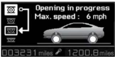
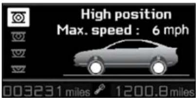
Maximum height
Changing a wheel (not possible if speed > 6mph (10km/h)).
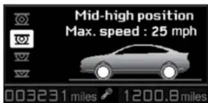
Intermediate position
For increased ground clearance (not possible if speed > 25 mph (40 km/h)).
For use on diffi cult roads when travelling at reduced speed, as well as on car park ramps.
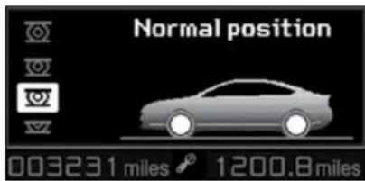
Normal position
If the speed authorised for a particular position is exceeded, the vehicle reverts automatically to the normal position.
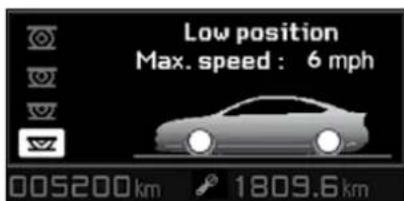
Minimum height
To facilitate loading or unloading the vehicle.
For workshop inspections.
Not to be used in normal driving (not possible if speed > 6mph (10km/h)).
DRIVING
Position not authorised
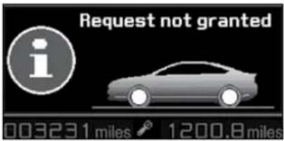
The instrument panel screen temporarily displays a message indicating that this position is not authorised.
The vehicle remains in the authorised position and the instrument panel screen indicates this position to you.
Automatic variation of ground clearance
- If your speed exceeds 70 mph (approx. 110 km/h), on a good road surface, ground clearance is lowered. The vehicle returns to its normal position if the road surface deteriorates or if your speed is lower than 55 mph (approx. 90 km/h).
- At low or medium speed, if the road surface is poor, ground clearance is increased. The vehicle returns to its normal position as soon as conditions allow.
- On switching off the ignition, the ground clearance is reduced to the parking position
For your safety if you are operating underneath the vehicle, you must support the vehicle with axle stands.
CHECKS
BONNET
Opening
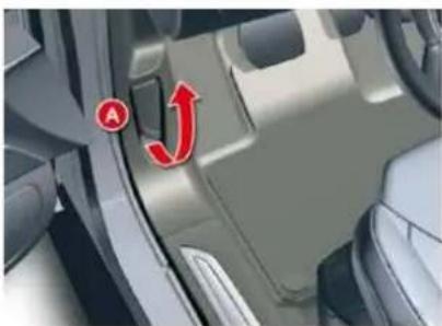
natural_image
Interior view of a car showing the door and seat area with a red arrow indicating direction (no text or symbols)Open the front passenger door.
Pull the interior bonnet release lever A, located at the bottom of the door frame.
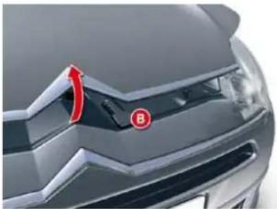
natural_image
Close-up of a car's front grille with a red circular logo and letter B mark (no readable text or symbols)Lift the safety catch B and raise the bonnet.
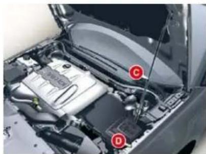
natural_image
Interior view of a car engine bay with labeled components (C and D), no visible text or symbols beyond labelsUnclip the stay C from its housing and pivot it to insert it in the notch D indicated by a yellow arrow.
Fix the stay in the notch to hold the bonnet open.
To avoid any risk of burns, only handle the bonnet stay by its yellow end.
The location of the interior release lever prevents opening of the bonnet while the front passenger's door is closed.
This operation must only be carried out when the vehicle is stationary. Avoid opening the bonnet in strong winds.
Closing
Take the stay out of the support notch.
Clip the stay in its housing.
Lower the bonnet then slam it firmly at the end of its travel.
Pull on the bonnet to check that it is fully closed.
CHECKS
BLEEDING THE DIESEL FUEL FILTER
Protective cover
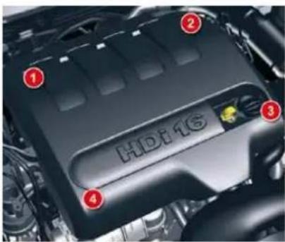
Removal of the cover
HDi 140 engine
Remove the protective cover by first unclipping at 3, then 1 and 4.
Unclip at 2 by pulling towards you, then lift up.
HDi 110, HDi 163 and V6 HDi 240 engines
Pull the protective cover upwards to remove it.
Refi tting
Firstly clip in at 2.
Lower and centre the cover.
Clip in at 3 and 4, pushing vertically and gently from the rear.
Clip in at 1 pushing vertically.
Bleeding water from the fuel filter
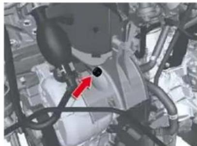
natural_image
Mechanical assembly diagram showing engine components and a red arrow indicating a specific part (no text or labels present)Bleed regularly (at each oil change). To bleed the water, slacken the bleed screw or the water in diesel fuel sensor, located at the base of the filter.
Continue until all the water has flowed out.
Then retighten the bleed screw or the water detection sensor.
X
CHECKS
RUNNING OUT OF FUEI (DIESEL)
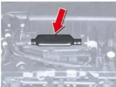
natural_image
Close-up of a mechanical component with a red downward arrow indicating compression or dislocation (no visible text or symbols)HDi 110 engine
F Unclip the protective cover to gain access to the priming pump.
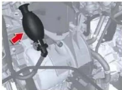
natural_image
Close-up of a mechanical component with a black bottle and red arrow indicator (no visible text or symbols)HDi 140 and HDi 163 engines
Unclip the protective cover to gain access to the priming pump.
Priming the fuel system
In the event of running out of fuel:
after filling (minimum 5 litres) and removing the protective cover, operate the manual priming pump, until some resistance is felt,
operate the starter motor while depressing the accelerator pedal slightly until the engine starts.
If the engine fails to start at the first attempt, wait fifteen seconds before trying again.
If the engine fails to start after a few attempts, operate the priming pump again and then try to start the engine.
When the engine is idling, accelerate slightly to complete the bleeding of the circuit.
V6 HDi 240 engine with electric pump
In the event of running out of fuel:
after adding fuel, turn the ignition key to position M, wait for a few seconds,
operate the starter motor until the engine starts.
If the engine fails to start after several attempts, contact a CITROËN dealer.
! HDi engines make use of advanced technology.
All maintenance and repairs require special qualifications which only a CITROEN dealer can guarantee.
CHECKS
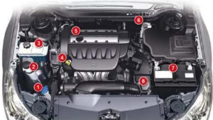
1.6i 16V/1.8i 16V
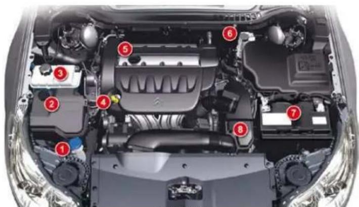
2.0i 16V
PETROL ENGINES
The various caps and covers allow access for checking fluid levels and for replacing certain components.
- Screenwash and headlamp wash reservoir.
- Power steering fl uid reservoir or power steering and suspension fl uid reservoir.
- Engine coolant reservoir.
- Engine oil dipstick.
- Engine oil fi ller cap.
- Brake fluid reservoir.
- Battery.
- Air fi Iter.
X
! Vehicles fi tted with the 2.0i 16v engine may be fi tted with metal suspension. In this case, a different power steering fi uid reservoir is fi tted.
CHECKS
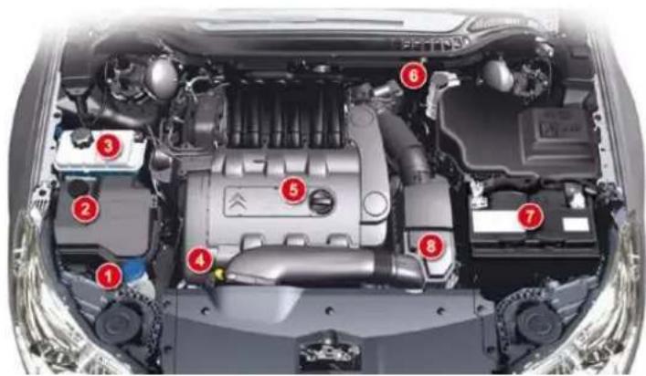
3.0i V6
3 litre V6 petrol engine
- Screen wash and headlamp wash reservoir.
- Power steering and suspension fluid reservoir.
- Engine coolant reservoir.
- Engine oil fi ller cap.
- Engine oil topping-up.
- Brake fluid reservoir.
- Battery.
- Air fi Iter.
CHECKS
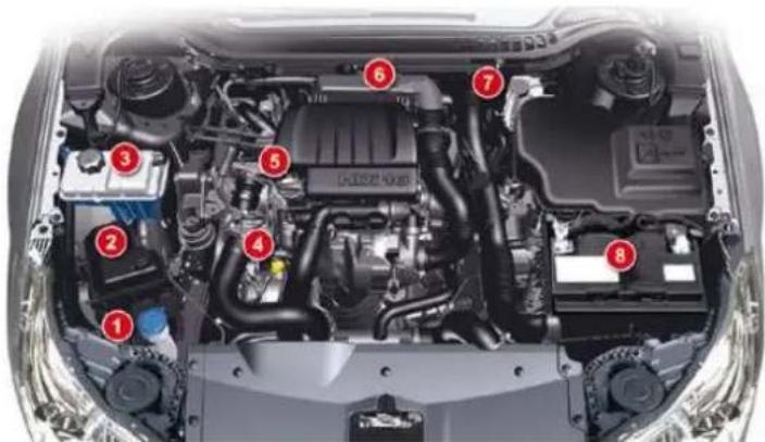
HDi 110
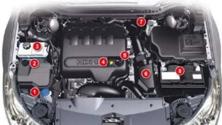
HDi 140
DIESEL ENGINES
The various caps and covers allow access for checking fluid levels, for replacing certain components and for priming the fuel system.
- Screenwash and headlamp wash reservoir.
- Power steering fluid reservoir or power steering and suspension fluid reservoir, depending on equipment.
- Engine coolant reservoir.
- Engine oil dipstick.
- Engine oil fi Iler cap.
- Air fi Iter.
- Brake fluid reservoir.
- Battery.

As the diesel circuit is pressurised, any work on this circuit is prohibited.
Vehicles fitted with the HDi 140 engine may be fitted with metal suspension. In this case, a different power steering fluid reservoir is fitted.
CHECKS
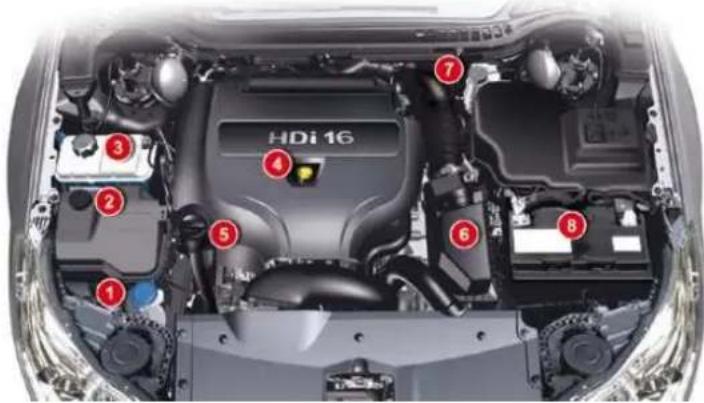
HDi 163
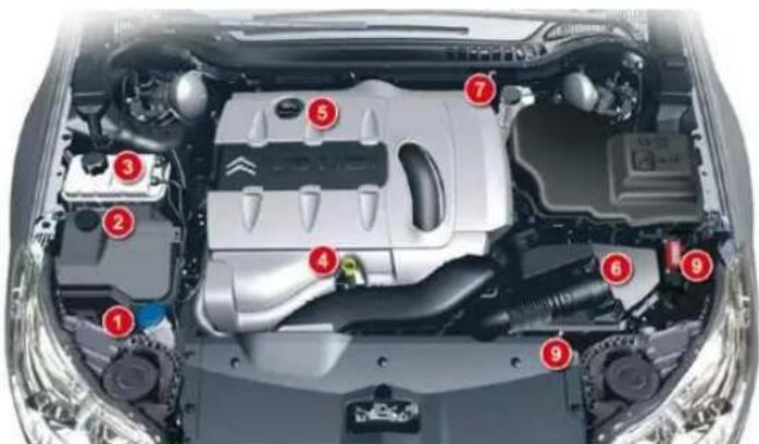
V6 HDi 240
HDi 163 - V6 HDi 240 engines (with particle filter)
- Screen wash and headlamp wash reservoir.
- Power steering and suspension fluid reservoir.
- Engine coolant reservoir.
- Engine oil dipstick.
- Engine oil fi ller cap.
- Air fi Iter.
- Brake fluid reservoir.
- Battery.
- "+" and "-" terminals for starting with a slave battery.
The Diesel fuel system being under high pressure:
- Any work on the system is prohibited.
- HDi engines make use of advanced technology.
All maintenance and repairs require special qualifications which only a CITROEN dealer can guarantee.
CHECKS
CHECKING LEVELS
Check all of these levels regularly and top them up if necessary, unless otherwise indicated.
If a level drops signifi cantly, have the corresponding system checked by a CITROËN dealer.
Oil level

The reading will only be correct if the vehicle is on level ground and the engine has been off for more than 15 minutes.
The check is carried out either when the ignition is switched on using the oil level indicator on the instrument panel, or using the dipstick.
Check this level also between each scheduled service and before long journeys.
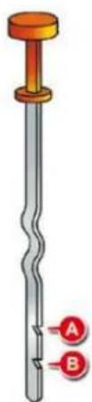
natural_image
Illustration of a mechanical screw with two labeled points A and B (no text or symbols on the object itself)Dipstick
There are 2 marks on the dipstick:
- A = max; never exceed this level,
- B = min; top up the level via the oil filler cap, using the type of oil suited to your engine.
Oil change
Refer to the Maintenance and Warranty Guide for details of the interval for this operation.

In order to maintain the reliability of the engine and emission control system, the use of additives in the engine oil is prohibited.
Oil specifi cation
The oil must correspond to your engine and conform to the manufacturer's recommendations.
Brake fluid level

The brake fluid level should be close to the "MAX" mark. If it is not, check the brake pad wear.
Fluid change
Refer to the Maintenance and Warranty Guide for details of the interval for this operation.
This fluid must be changed regularly. Fluid which has been used excessively may cause a loss of braking efficiency.
Fluid specifi cation
The brake fluid must conform to the manufacturer's recommendations and meet the DOT4 standard.
Power steering fluid or power steering and suspension fluid level

This fluid must be topped up by a CITROËN dealer.
CHECKS
Coolant level

The coolant level should be close to the "MAX" mark but should never exceed it.
When the engine is warm, the temperature of the coolant is regulated by the fan. This can operate with the ignition off.
On vehicles which are fitted with a particle emission filter, the fan may operate after the vehicle has been switched off, even if the engine is cold.
In addition, as the cooling system is pressurised, wait at least one hour after switching off the engine before carrying out any work.
To avoid any risk of scalding, unscrew the cap by two turns to allow the pressure to drop. When the pressure has dropped, remove the cap and top up the level.
Coolant change
The coolant does not have to be changed.
Fluid specifi cation
The coolant must conform to the manufacturer's recommendations.
Screenwash and headlamp wash fluid

In the case of vehicles fitted with headlamp washers, the minimum level of this fluid is indicated by an audible sig-
nal and a message on the multifunction screen.
Top up the level when you stop the vehicle.
Fluid specifi cation
For optimum cleaning and to avoid freezing, this fluid must not be topped up or replaced with water.
Reservoir capacities:
- screenwash: approximately 3.5 litres,
- screenwash and headlamp wash: approximately 6.15 litres.
Diesel additive level (Diesel engine with particle emission filter)
A low additive level is indicated by lighting of the service warning lamp, accompanied by an audible warning and a message on the multifunction screen.
Topping up
This additive must be topped up by a CITROËN dealer without delay.
Used products

Avoid prolonged contact of used oil or fluids with the skin.
Most of these fluids are harmful to health or indeed very corrosive.

Do not discard used oil or fl u-ids into sewers or onto the ground.
Take used oil to a CITROËN dealer (France) or an authorised waste disposal site.
CHECKS
CHECKS
Unless otherwise indicated, check these components in accordance with the Warranty and Maintenance Record and according to your engine. Otherwise, have them checked by a CITROËN dealer.
Battery

The battery does not require any maintenance. However, check that the terminals are clean and correctly tightened, particularly in summer and winter.
When carrying out work on the battery, refer to the "Practical information" section for details of the precautions to be taken before disconnecting the battery and following its reconnection.
Air filter and passenger compartment filter

Refer to the Warranty and Maintenance Record for details of the replacement intervals for these components.
Depending on the environment (e.g. dusty atmosphere) and the use of the vehicle (e.g. city driving), replace them twice as often if necessary (refer to the "Engines" paragraph).
A clogged passenger compartment filter may have an adverse effect on the performance of the air conditioning system and generate undesirable odours.
Oil filter

Replace the oil fi Itereach time the engine oil is changed.
Refer to the Warranty and Maintenance Record for details of the replacement interval for this component.
Particle filter system (Diesel)
Complementary to the catalytic converter, this filter makes an active contribution to the preservation of air quality by the retaining of the unburnt pollutant particles. Black exhaust fumes are thus no longer emitted.
After prolonged idling or driving at very low speeds, you may occasionally notice water vapour being emitted from the exhaust when accelerating. This is of no consequence to the running of the vehicle or to the environment.
If there is risk of clogging, a message appears on the instrument panel display, accompanied by an audible signal and lighting of the service warning lamp.
This alert tells you that the particle filter is starting to fill up (in conditions of urban driving of exceptionally long duration: low speeds, traffi c jams etc.).
To regenerate the filter, it is advised to drive as soon as possible, when traffic conditions permit, at a speed of 40 mph (around 60 km/h) or more for at least five minutes (until the alert message disappears).
If this alert persists, consult a CITROËN dealer.
CHECKS
Manual gearbox

The gearbox does not require any maintenance (no oil change).
Refer to the Maintenance and Warranty Guide for the details of the level checking interval for this component.
Automatic gearbox

The gearbox does not require any maintenance (no oil change).
Refer to the Warranty and Maintenance Record for details of the level checking interval for this component.
Brake disc wear

For information relating to checking the brake disc wear, contact a CITROËN dealer.
Parking brake

If a loss of effectiveness of this system is noticed, the parking brake must be checked, even between two services.
This system must be checked by a CITROËN dealer.
Only use products recommended by CITROËN or products of equivalent quality and specifications.
Do not use a dry cloth with an abrasive product for the maintenance of aluminium parts; use a sponge and soapy water.
In order to optimise the operation of units as important as the braking system, CITROËN selects and offers very specific products.
To avoid damaging the electrical units, the use of a high pressure washer in the engine compartment is strictly prohibited.
Brake pads

Brake wear depends on the style of driving, particularly in the case of vehicles used in town, over short distances. It may be
necessary to have the condition of the brakes checked, even between vehicle services.
Unless there is a leak in the circuit, a drop in the brake fluid level indicates that the brake pads are worn.
PRACTICAL INFORMATION
TEMPORARY PUNCTURE REPAIR KIT
Complete system consisting of a compressor and a bottle of sealant product which permits temporary repair of the tyre so that you can drive to the nearest garage.
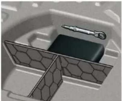
natural_image
Illustration of a mechanical component with a tool and block, no visible text or symbolsThe kit is located in the boot under the floor.
This repair kit is available from CITROËN dealers.
It is designed to repair holes of a maximum diameter of 6 mm, located exclusively on the tyre tread or shoulder. Avoid removing any foreign bodies which have penetrated the tyre.
Using the kit
Switch off the ignition.
Affi x the speed limitation sticker to the vehicle's steering wheel to remind you that a wheel is in temporary use.
Check that the switch A is in position "0".
Connect the pipe of the bottle 1 to the valve of the tyre to be repaired.
^18 Connect the compressor's electric plug to the vehicle's 12 V socket.
Start the vehicle and leave the engine running.
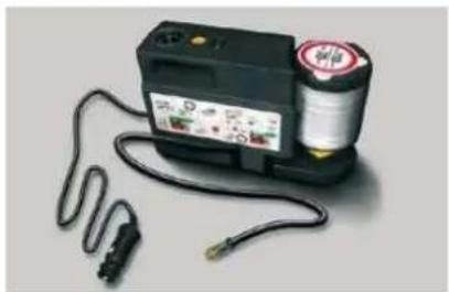
natural_image
Electric pressure testing device with attached cable and connector (no visible text or symbols)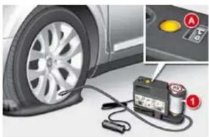
natural_image
Close-up of a car tire and an electric shock absorber with a labeled sensor (no text or symbols visible)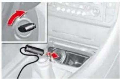
natural_image
Close-up of a car interior showing a plug inserted into a sink with a red arrow pointing to the switch (no text or symbols visible)PRACTICAL INFORMATION
Switch on the compressor by moving the switch A to position "1" until the tyre pressure reaches 2.0 bars.
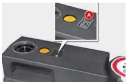
natural_image
Close-up of a black electronic device with circular ports and a highlighted indicator (no text or symbols visible)If this pressure has not been reached after approximately five to ten minutes, the tyre cannot be repaired; contact a CITROËN dealer to have your vehicle repaired.
Remove the compressor and unclip and store the bottle in a sealed bag to avoid staining your vehicle with traces of fluid.
Drive immediately for approximately two miles (three kilometres), at reduced speed (between 15 and 35 mph [20 and 60 km/h]), to plug the puncture.
Stop to check the repair and the pressure.
Connect the compressor pipe directly to the valve of the repaired wheel.
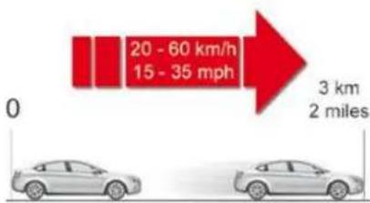
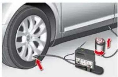
natural_image
Close-up of a car tire mounted on its wheel next to an electrical testing device and battery (no visible text or symbols)PRACTICAL INFORMATION
Connect the compressor's electric plug to the vehicle's 12 V socket again.
Start the vehicle again and leave the engine running.
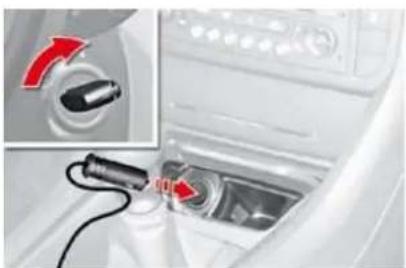
natural_image
Close-up of a car interior showing a plug inserted into a vent, with a red arrow indicating the switch (no text or symbols visible)Adjust the pressure using the compressor (to inflate: switch A in position "1"; to deflate: switch A in position "0" and press button B), in accordance with the vehicle's tyre pressure label (located on the door aperture on the left-hand side), then remember to check that the leak has been plugged correctly (no further loss of pressure after several miles [kilometres]).
Remove the compressor, then store the whole kit.
Drive at reduced speed (50 mph [80 km/h] max) limiting the distance travelled to approximately 120 miles (200 km).
Visit a CITROËN dealer as soon as possible to have the tyre repaired or replaced by a technician.
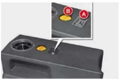
natural_image
3D rendered mechanical component with circular ports and a highlighted section showing two labeled buttons (A and B) — no text or symbols present.Take care as the bottle of sealant contains ethylene-glycol. This product is harmful if swallowed and causes irritation to the eyes. Keep it out of reach of children.
The expiry date of the fluid is indicated on the base of the bottle. The bottle is designed for a single use; even if only partly used, it must be replaced.
After use, do not discard the bottle into the environment, take it to an authorised waste disposal site CITROËN.
Do not forget to obtain a new bottle of sealant, available from CITROËN dealers.
If the vehicle is fitted with tyre under-inflation detection, the tyre under-inflation warning lamp will remain on after the wheel has been repaired until the system is reinitialised by a CITROËN dealer.
XI
PRACTICAL INFORMATION
CHANGING A WHEEL
Access to the tools
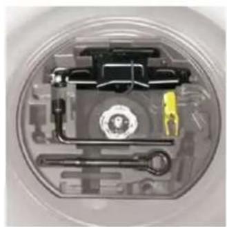
natural_image
Cross-sectional view of a mechanical assembly with gears and a central component (no visible text or symbols)The tools are to be found in a protective holder inside the spare wheel.
Pull back the retaining strap for access.
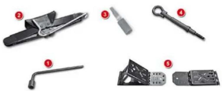
List of tools
All of these tools are specific to your vehicle and may vary according to equipment. Do not use them for any other purpose.
- Wheelbrace
- Jack
- Tool for the removal/refitting of bolt protectors
- Towing eye
- Moveable chock
PRACTICAL INFORMATION
Access to the spare wheel
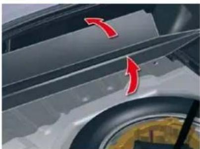
natural_image
Close-up of a car's side panel with red arrows pointing to the edge (no text or symbols visible)To remove the spare wheel
Lift up the boot floor and fold in two (Saloon) or hook it using the retractable handle (Tourer).
Detach the strap then push the wheel forwards so as to be able to lift it.
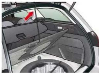
natural_image
Interior view of a car showing the rear window, windshield, and side panel with a red arrow pointing to the side (no text or symbols visible)To reposition the spare wheel
Position the spare wheel flat in the boot, then pull it towards you.
^c Next place the toolbox inside the wheel, then secure the assembly with the strap.
Release the boot floor to return it to its initial position.
The tyre pressures are indicated on the label located on the left-hand centre door pillar. Tyre pressures are given for different vehicle loading conditions.
XI
PRACTICAL INFORMATION
Removing a wheel
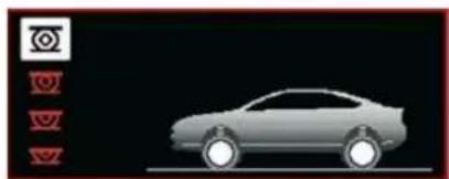
natural_image
Side view of a silver sedan car against black background, with no visible text or symbolsPark the vehicle on stable, firm ground that is not slippery. apply the parking brake.
If your vehicle is equipped with "Hydractive III+" suspension, with the engine running at idle, adjust the ground clearance to its maximum height.
Switch off the ignition and engage first gear or reverse gear depending on any slope (for a vehicle with automatic gearbox, select position P).
If your vehicle is fitted with "Hydractive III+" suspension, position the chock, whichever direction the gradient may be in, in front of the front wheel diametrically opposite to the one to be replaced.
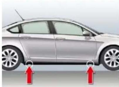
natural_image
Side view of a silver sedan with two red arrows pointing to the side, indicating measurement or alignment points (no text or symbols present)Position the jack at one of the four jacking-points provided on the underbody close to the wheels, then use the wheelbrace to unwind the jack until it reaches the ground.
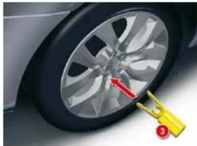
natural_image
Close-up of a car wheel rim with a yellow clip attached, showing red annotation arrows (no text or symbols)Remove the protector from each bolt using tool 3.
Slacken the wheel bolts.
Continue to extend the jack until the wheel is a few centimetres off the ground.
^2 Undo the bolts, remove the wheel.

Before positioning the jack:
Always adjust the vehicle's ground clearance to the "maximum height" position and retain this adjustment for as long as the jack is under the vehicle (do not use the hydraulic adjustments),
Immobilise your vehicle on horizontal, stable and non-slippery ground,
Ensure that any passengers have left the vehicle and are in a safe place.
Never get underneath the vehicle if it is supported only by the jack.
The jack and all of the tools are specific to your vehicle. Do not use them for any other applications.
Have the original wheel repaired and refitted as soon as possible.
PRACTICAL INFORMATION
Wheel for temporary use
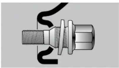
natural_image
Technical illustration of a mechanical connector with threaded shaft and threaded end (no text or symbols)Your vehicle may be fitted with a spare wheel which is different to those on the vehicle. When fitting the spare wheel, it is normal to notice that the wheel bolt washers do not come into contact with the wheel rim. The spare wheel is secured by the conical tapering of the wheel bolt's shaft.
When refitting the original wheel, ensure that the wheel bolt contact surfaces are clean and in good condition.
Fitting a wheel
Fit the wheel on the hub, using the centring guide. Make sure that the contact surface between the hub and the wheel is clean.
Screw in the bolts but do not fully tighten them.
Lower the jack and remove it.
Tighten the wheel bolts, using the wheelbrace.
Refi t the protectors on the bolts.
Return the ground clearance to the normal position.
Ensure the tyre pressure is correct and have the balancing checked.
Deflation detection
These wheels have tyre pressure sensors. It is essential to have repairs carried out by a CITROËN dealer.
Security bolts
Each wheel is equipped with one security bolt.
To remove it:
Remove the protector using tool 3.
Use the security socket with the wheelbrace.
If your vehicle is fitted with a spare wheel of a different size to those on the vehicle, you must not exceed 50 mph (80 km/h) whilst using the spare wheel.
The wheel bolts are specific to the type of wheel.
If the type of wheel is changed, check with your CITROËN dealer that the wheel bolts are compatible with the new wheels.
Take care to note down the code number engraved on the head of the security bolt socket. This will enable you to obtain a replacement security bolt socket from a CITROËN dealer.
PRACTICAL INFORMATION
Wheel for temporary use
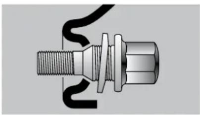
natural_image
Technical illustration of a mechanical connector with threaded shaft and threaded end (no text or symbols)Your vehicle may be fitted with a spare wheel which is different to those on the vehicle. When fitting the spare wheel, it is normal to notice that the wheel bolt washers do not come into contact with the wheel rim. The spare wheel is secured by the conical tapering of the wheel bolt's shaft.
When refitting the original wheel, ensure that the wheel bolt contact surfaces are clean and in good condition.
Fitting a wheel
Fit the wheel on the hub, using the centring guide. Make sure that the contact surface between the hub and the wheel is clean.
Screw in the bolts but do not fully tighten them.
Lower the jack and remove it.
Tighten the wheel bolts, using the wheelbrace.
Refi t the protectors on the bolts.
Return the ground clearance to the normal position.
Ensure the tyre pressure is correct and have the balancing checked.
Deflation detection
These wheels have tyre pressure sensors. It is essential to have repairs carried out by a CITROËN dealer.
Security bolts
Each wheel is equipped with one security bolt.
To remove it:
Remove the protector using tool 3.
Use the security socket with the wheelbrace.
If your vehicle is fitted with a spare wheel of a different size to those on the vehicle, you must not exceed 50 mph (80 km/h) whilst using the spare wheel.
The wheel bolts are specific to the type of wheel.
If the type of wheel is changed, check with your CITROËN dealer that the wheel bolts are compatible with the new wheels.
Take care to note down the code number engraved on the head of the security bolt socket. This will enable you to obtain a replacement security bolt socket from a CITROËN dealer.
PRACTICAL INFORMATION
CHANGING A BULB
Headlamps
Model with Xenon headlamps (D1S)

The headlamps are fitted with polycarbonate glass with a protective coating:
do not clean them using a dry or abrasive cloth, nor with a detergent or solvent product,
use a sponge and soapy water,
when using a high pressure washer on persistent marks, do not direct at the lamps or their outlines for too long, so as not to damage their protective coating and seals.
Do not touch the bulb directly with your fingers, use lint-free cloths.
Changing a halogen bulb should only be done after the headlamp has been switched off for a few minutes (risk of serious burns).
It is imperative to use only anti-ultraviolet (UV) type bulbs in order not to damage the headlamp.
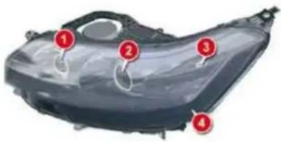
- Sidelamps: W5W
- Dual-function Xenon headlamps (dipped/main): D1S
- Angular lighting: HP19
- Daytime running lamps: HP24
For the maintenance of the front headlamp unit and the changing of HP19, D1S and HP24 bulbs, contact a CITROËN dealer.
Risk of electrocution
Xenon bulbs must be replaced by a CITROËN dealer.
You are advised to change both D1S bulbs at the same time, if one of them has failed.
PRACTICAL INFORMATION
Sidelamps
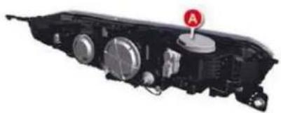
natural_image
Internal components of a vehicle head assembly (no visible text or symbols)Remove the protective cap A.
Pull the bulb holder to remove it.
Replace the bulb and refit the bulb holder.
Refit the protective cap A.
Model with halogen headlamps
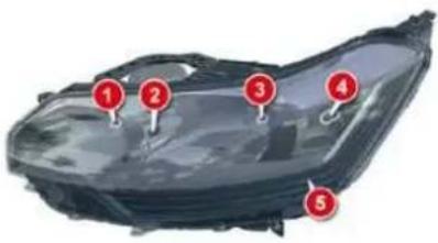
- Main beams: H1
- Sidelamps: W5W
- Dipped beams: H7
- Directional lighting: H7
- Daytime running lamps: HP24
For the maintenance of the front headlamp unit and changing HP24 bulbs, contact a CITROËN dealer.
Main beams
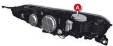
natural_image
Internal components of a vehicle headstock with no visible text or symbolsRemove the protective cap A.
Disengage the retaining spring.
Remove the bulb and replace it, paying attention to the direction of fl tting.
Refi t the retaining spring.
Refit the protective cap A.
PRACTICAL INFORMATION
Sidelamps
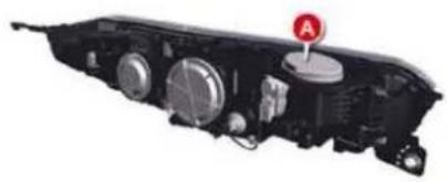
natural_image
Mechanical component with circular components and a red circular symbol labeled 'A' (no readable text or symbols beyond the label)Remove the protective cap A.
Pull the bulb holder to remove it.
Replace the bulb and refit the bulb holder.
Refit the protective cap A.
Dipped beam
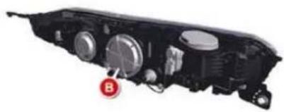
natural_image
Close-up of a mechanical component with circular features and a red circular marker labeled 'B' (no readable text or symbols beyond the label)Remove the protective cap B.
Disconnect the connector by pressing it between the thumb and index finger.
^B Free the bulb from its two metal clamps.
Take out the bulb.
Replace the bulb, exerting a slight axial force.
Refi t the connector, until it is all the way in.
Refit the protective cap B.
Directional lamp
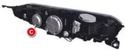
natural_image
Internal components of a vehicle headstock with visible motors and wiring (no text or symbols)Remove the protective cap C.
- Disconnect the connector by pressing it between the thumb and index finger.
Free the bulb from its two metal clamps.
Take out the bulb.
Replace the bulb, exerting a slight axial force.
Refi t the connector, until it is all the way in.
Refit the protective cap C.
PRACTICAL INFORMATION
Direction indicators
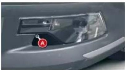
natural_image
Close-up of a car's front bumper with a red circular icon labeled 'A' (no readable text or symbols beyond the label)Remove the fixing screw of cover A using a torx tool, tip the cover over and remove.
Remove the fixing screw of lamp B using a torx tool and pull the headlamp unit to remove it from the bumper.
^27 Detach the bulb C by pressing on bars 1 and 2.
Disconnect the connector (pull whilst pressing on the grey tongue using a fl at screwdriver).
Replace the bulb.
Refit the connector (push the grey tongue in well).
Refit the headlamp unit in the bumper.
Screw the headlamp unit in.
- Position the cover using its guides and screw in.
Bulbs: HP24W
Front foglamp
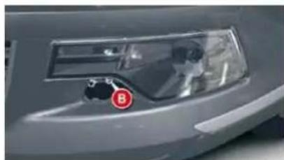
natural_image
Close-up of a car's front bumper with a red 'B' marking on the nose (no visible text or symbols)Remove the fixing screw of cover A using a torx tool, tip the cover over and remove.
Remove the fixing screw of lamp B using a torx tool and pull the headlamp unit to remove it from the bumper.
Disconnect the connector D.
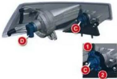
natural_image
Mechanical assembly diagram showing a motor and gear components with labeled parts (D, C, 1, 2), no readable text or symbols beyond labels.Remove the bulb by performing a quarter of a turn.
Replace the bulb.
Refit the connector D.
Refit the headlamp unit in the bumper.
Screw the headlamp unit in.
- Position the cover using its guides and screw in.
Bulbs: H8
XI
PRACTICAL INFORMATION
Side repeaters
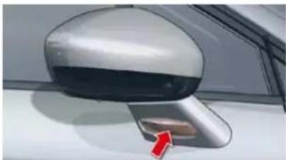
natural_image
Close-up of a car side mirror with a red arrow pointing to the front wheel (no text or symbols visible)The side repeater is sealed.
If the bulb is faulty, replace the side repeater.
Consult a CITROËN dealer.
When refi tting, take care not to trap the electrical cables.
Rear lamps (Saloon) Boot-mounted lamps
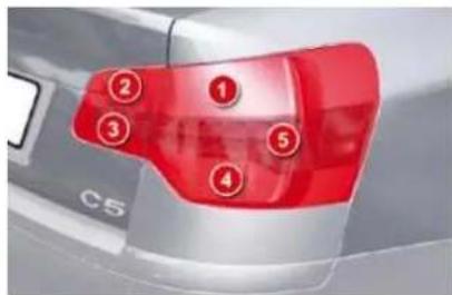
Identify the failed bulb.
-
Stop lamps and sidelamps: P21 W/5W
-
Sidelamps: R5W
- Reversing lamp: H21W
- Foglamps: H21W
- Direction indicators: P21W
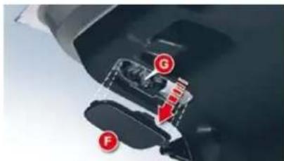
natural_image
Close-up of a mechanical assembly with labeled parts (G, F) and a red arrow indicating direction (no readable text or symbols)Open the boot.
F Using a fl at screwdriver, remove the 3 clips which fix the trim in the lamp area.
Partially remove the trim F.
Disconnect the connector G.
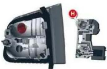
natural_image
Cutaway view of a mechanical device showing internal components and a close-up view with a red circular symbol labeled 'H' (no text or symbols present)F Detach the bulb holder H.
F Replace the bulb.
Refit the bulb holder H.
Refit the connector G.
Replace and fix the trim F with its clips.
PRACTICAL INFORMATION
Side repeaters
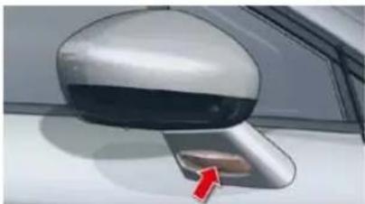
natural_image
Close-up of a car side mirror with a red arrow pointing to the front wheel (no text or symbols visible)The side repeater is sealed.
If the bulb is faulty, replace the side repeater.
Consult a CITROËN dealer.
When refi tting, take care not to trap the electrical cables.
Rear lamps (Saloon) Boot-mounted lamps
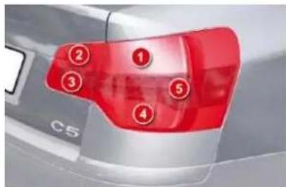
Identify the failed bulb.
-
Stop lamps and sidelamps: P21 W/5W
-
Sidelamps: R5W
- Reversing lamp: H21W
- Foglamps: H21W
- Direction indicators: P21W
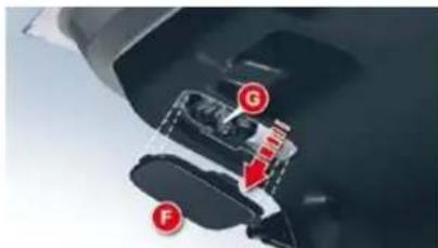
Open the boot.
F Using a fl at screwdriver, remove the 3 clips which fix the trim in the lamp area.
Partially remove the trim F.
Disconnect the connector G.
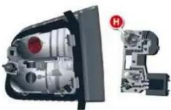
natural_image
Cutaway view of a mechanical device showing internal components and a close-up view with a red circular symbol labeled 'H' (no text or symbols present)F Detach the bulb holder H.
F Replace the bulb.
Refit the bulb holder H.
Refit the connector G.
Replace and fix the trim F with its clips.
PRACTICAL INFORMATION
Wing-mounted lamps
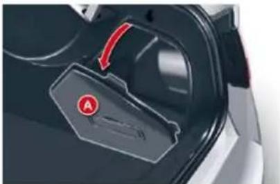
natural_image
Close-up of a car interior showing a black plastic door with red control panel and a red circular logo (no visible text or symbols)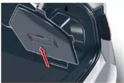
natural_image
Close-up of a car's front compartment showing a black plastic door and red arrow pointing to the door (no text or symbols visible)Remove the lateral boot trim flap A. To do so, pull it towards the inside of the boot, then pull it upwards.
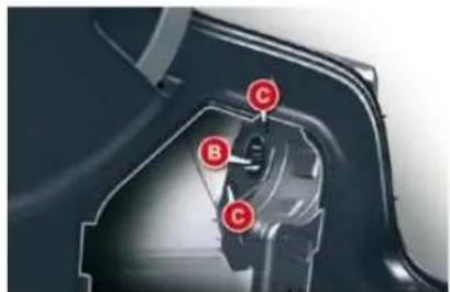
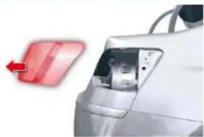
natural_image
Close-up of a white car's side panel with a red arrow pointing to the front panel (no text or symbols visible)Disconnect connector B.
Unscrew the 2 fixings C.
Remove the lamp from its housing.
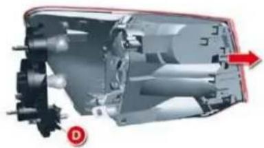
natural_image
Cross-sectional diagram of a mechanical device showing internal components and fluid flow direction (no text or symbols)Detach the bulb holder D.
Replace the bulb.
Refit the bulb holder D.
Place the lamp in its housing.
Screw in the 2 fixings C.
Refit connector B.
Refit the trim A.
You can use the wheelbrace to screw or unscrew the fixings C.
PRACTICAL INFORMATION
Rear lamps (TourerBoot-mounted lamps
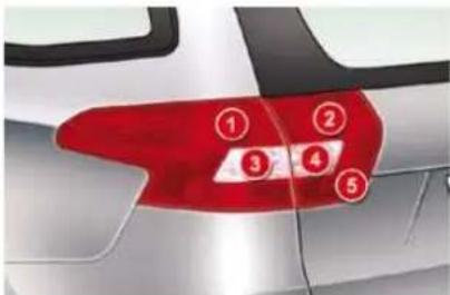
Identify the failed bulb.
- Stop lamps and sidelamps: P21 W/5W
- Sidelamps: R5W
- Reversing lamp: H21W
- Foglamps: H21W
- Direction indicators: P21W
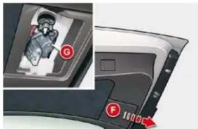
Open the boot.
Using a fl at screwdriver, remove the 3 clips which fix the trim in the lamp area.
Partially remove the trim F.
Disconnect the connector G.
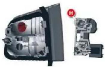
natural_image
Cutaway view of a mechanical device showing internal components and a close-up view with a red circular symbol labeled 'H' (no text or symbols present)Detach the bulb holder H.
Replace the bulb.
Refit the bulb holder H.
Refit the connector G.
Replace and fix the trim F with its clips.
PRACTICAL INFORMATION
Wing-mounted lamps
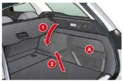
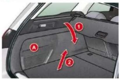
Remove the lateral boot trim A.
To do so:
Pull it towards towards the inside of the boot.
Pull it upwards.
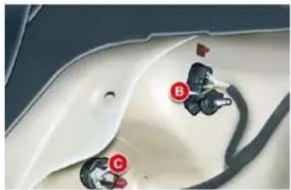
natural_image
Close-up of a white car hood with black and red buttons labeled B, C, and D (no readable text or symbols)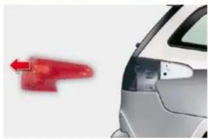
natural_image
Side view of a silver car with a red light trail and arrow pointing left (no text or symbols)Disconnect the connector B.
Unscrew the fixing screw C.
Remove the lamp from its housing.
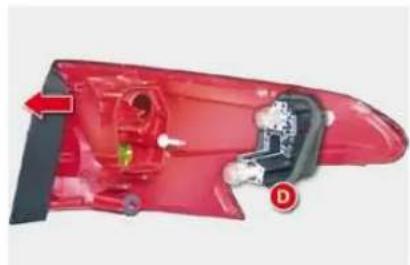
natural_image
Red automotive body panel with mechanical components and a red arrow indicating direction (no text or symbols)Detach the bulb holder D.
Replace the faulty bulb.
Refit the bulb holder D.
Place the lamp in its housing.
Screw in the fixing screw C.
Refit the connector B.
Refit the trim A.
You can use the wheelbrace to screw or unscrew the fixing screw C.
PRACTICAL INFORMATION
Number plate lamps (W5W)
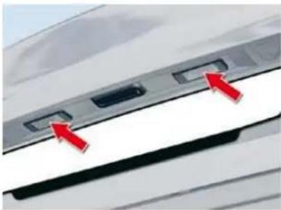
natural_image
Close-up of a car rear panel with two red arrows pointing to specific slots (no text or symbols visible)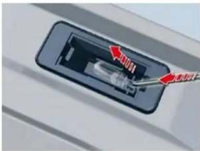
natural_image
Close-up of a device component with red arrows indicating direction, no visible text or symbolsThird brake lamp (diodes)
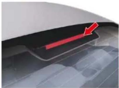
natural_image
Close-up of a car's rear bumper area with a red arrow pointing to the bumper area (no text or symbols visible)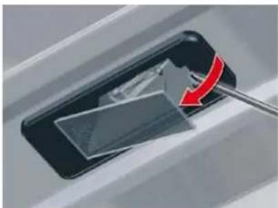
natural_image
Close-up of a car's door panel with a red arrow indicating rotation (no text or symbols visible)Remove the lens.
Change the faulty bulb.
For the replacement of this type of diode lamp, contact a CITROËN dealer.
Insert a thin screwdriver into one of the external holes of the lens.
Push it outwards to unclip it.
PRACTICAL INFORMATION
Interior lamps
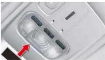
natural_image
Close-up of a white electronic device with a transparent display case and indicator lights (no visible text or symbols)Roof lamps
Unclip the transparent cover of the roof lamp to reach the bulb.
Bulb: W5W
Boot lamp
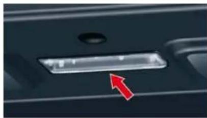
natural_image
Close-up of a dark mechanical component with a red arrow pointing to a rectangular slot (no text or symbols visible)Detach the cover and use a W5W bulb.
Floor lighting
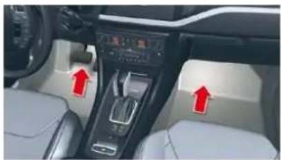
natural_image
Interior view of a car dashboard with red arrows pointing to the dashboard controls (no visible text or symbols)Detach the cover and use a W5W bulb.
Map reading lamp
Detach the cover.
If necessary, detach the partition of the affected map reading lamp.
Rear reading lamps (Tourer)
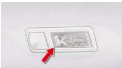
Detach the cover of the reading lamp to access the bulb.
Bulb: W5W
Pavement lighting
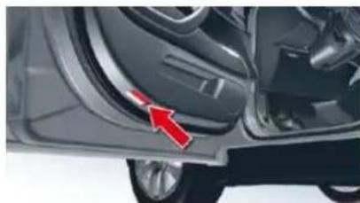
natural_image
Close-up of a car's side panel showing the wheel and door, with a red arrow pointing to the edge detail (no text or symbols visible)Detach the cover and use a W5W bulb.
Glovebox
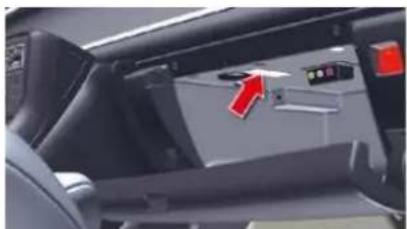
natural_image
Interior view of a car dashboard with visible seats, dashboard display, and red directional arrow (no text or symbols)Detach the cover and use a W5W bulb.
XI
PRACTICAL INFORMATION
CHANGING A FUSE
Operating procedure for replacing a faulty fuse with a new fuse to rectify a failure of the corresponding function.
The 2 fuseboxes are located below the dashboard and under the bonnet.
Replacing a fuse
Before replacing a fuse, you should ascertain the cause of the fault and have it remedied. The numbers of the fuses are indicated on the fusebox.
Replace the fuse that has blown with one of the same rating (same colour).
Use the special pliers 1 placed on the fl ap close to the fuseboxes. The fl ap also has spare fuses available.
Good
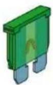
Bad
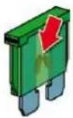
Pliers 1
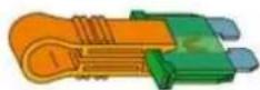
Fuses under the dashboard
Access to the fuses
fully open the storage box then pull firmly on it horizontally,
remove the trim by pulling sharply on the bottom.
When refi tting the storage box, observe the following advice:
- With the storage box horizontal, refi t the bottom ensuring that the lower cut-outs are in line with the pins.
- Give a sharp push to the front.
- Close the storage box, ensuring that the springs located behind pass over the top.
Fusebox A
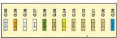
natural_image
Close-up of a car interior showing a black plastic door and seat (no text or symbols visible)
natural_image
Interior view of a mechanical device with internal components and no visible text or symbols
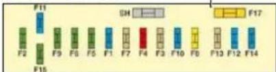
Fusebox C
Replacement fuses and pliers 1
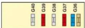
Fusebox B
PRACTICAL INFORMATION
CHANGING A FUSE
Operating procedure for replacing a faulty fuse with a new fuse to rectify a failure of the corresponding function.
The 2 fuseboxes are located below the dashboard and under the bonnet.
Replacing a fuse
Before replacing a fuse, you should ascertain the cause of the fault and have it remedied. The numbers of the fuses are indicated on the fusebox.
Replace the fuse that has blown with one of the same rating (same colour).
Use the special pliers 1 placed on the fl ap close to the fuseboxes. The fl ap also has spare fuses available.
Good
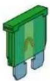
Bad
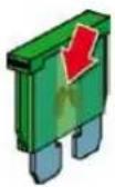
Pliers 1
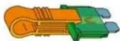
Fuses under the dashboard
Access to the fuses
fully open the storage box then pull firmly on it horizontally,
remove the trim by pulling sharply on the bottom.
When refi tting the storage box, observe the following advice:
- With the storage box horizontal, refi t the bottom ensuring that the lower cut-outs are in line with the pins.
- Give a sharp push to the front.
- Close the storage box, ensuring that the springs located behind pass over the top.
Fusebox A
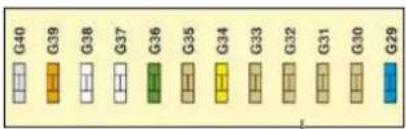
natural_image
Close-up of a car interior showing a black plastic door and seat (no text or symbols visible)
natural_image
Interior view of a mechanical device with internal components and no visible text or symbols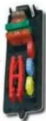
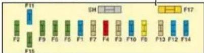
Fusebox C
Replacement fuses and pliers 1

Fusebox B
PRACTICAL INFORMATION
FUSEBOX 1
Table of fuses
| Fuse N° | Rating | Function |
| G29 | - | - |
| G30 | 5 A | Heated door mirrors |
| G31 | 5 A | Rain and brightness sensor |
| G32 | 5 A | Seat belt not fastened warning lamps |
| G33 | 5 A | Electrochrome rear view mirrors |
| G34 | 20 A | Sunroof (saloon) |
| G35 | 5 A | Passenger door lighting - passenger door mirror adjustment |
| G36 | 30 A | Electric tailgate (Tourer) |
| G37 | 20 A | Heated front seats |
| G38 | 30 A | Driver's electric seat |
| G39 | 30 A | Passenger's electric seat - HIFI amplifier |
| G40 | 3 A | Trailer relay unit supply |
FUSEBOX E
| Fuse N° | Rating | Function |
| G36 | 15 A | 6 speed automatic gearbox |
| 5 A | 4 speed automatic gearbox | |
| G37 | 10 A | Daytime running lamps - Diagnostic socket |
| G38 | 3 A | ESP |
| G39 | 10 A | Hydraulic suspension |
| G40 | 3 A | STOP switch |
PRACTICAL INFORMATION
FUSEBOX C
| Fuse N° | Rating | Function |
| F1 | 15 A | Rear screen wipe (Tourer) |
| F2 | 30 A | Locking and deadlocking relay |
| F3 | 5 A | Airbags |
| F4 | 10 A | Automatic gearbox - additional heater unit (Diesel) - electrochrome rear view mirrors |
| F5 | 30 A | Front window - sun roof - passenger door lighting - passenger door mirror adjustment |
| F6 | 30 A | Rear window |
| F7 | 5 A | Vanity mirror lighting - Glove box lighting - interior lamps - torch (Tourer) |
| F8 | 20 A | Radio - CD changer - Steering mounted controls - Screen - Deflation detection - Electric boot ECU |
| F9 | 30 A | Cigar-lighter - front 12 V socket |
| F10 | 15 A | Alarm - Steering mounted controls, lighting, signalling and wiper stalks |
| F11 | 15 A | Low current anti-theft switch |
| F12 | 15 A | Driver's electric seat - instrument panel - seat belt not fastened warning lamps - air conditioning controls |
| F13 | 5 A | Engine relay unit - Hydraulic suspension pump cut-off relay - airbag ECU supply |
| F14 | 15 A | Rain and brightness sensor - parking assistance - passenger's electric seat - trailer relay unit - HIFI amplifi er ECU - Bluetooth system - Lane Departure Warning System |
| F15 | 30 A | Locking and deadlocking relay |
| F17 | 40 A | Heated rear screen - exterior heated door mirrors |
| FSH | SHUNT | PARK SHUNT |
PRACTICAL INFORMATION
Fuses under the bonnet
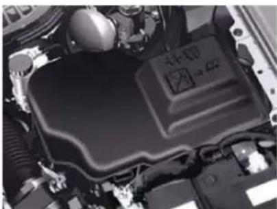
natural_image
Close-up of a car engine bay with visible internal components and no text or symbolsAccess to the fuses
Undo each screw by a 1/4 turn.
Change the fuse.
Table of fuses
| Fuse N° | Rating | Function |
| F1 | 20 A | Engine control unit |
| F2 | 15 A | Horn |
| F3 | 10 A | Screen wash pump |
| F4 | 10 A | Headlamp wash pump |
| F5 | 15 A | Engine actuators |
| F6 | 10 A | Air flow meter - Directional headlamps - Diagnostic socket |
| F7 | 10 A | Automatic gearbox lever lock - Power steering |
| F8 | 25 A | Starter motor |
| F9 | 10 A | Clutch switch - Stop switch |
| F10 | 30 A | Engine actuators |
| F11 | 40 A | Air conditioning blower |
| F12 | 30 A | Wipers |
| F13 | 40 A | BSI supply (ignition on) |
| F14 | 30 A | - |
| F15 | 10 A | Right-hand main beam |
| F16 | 10 A | Left-hand main beam |
| F17 | 15 A | Right-hand dipped beam |
| F18 | 15 A | Left-hand dipped beam |
| F19 | 15 A | Engine actuators |
| F20 | 10 A | Engine actuators |
| F21 | 5 A | Engine actuators |
After a repair, take care to reclose the cover.
Any repairs on the MAXI fuses (that give additional protection), located in the fuseboxes, must be left to a CITROËN dealer.
PRACTICAL INFORMATION
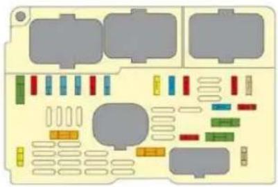
natural_image
Pure electrical circuit lines without any symbolsTable of fuses
| Fuse N° | Rating | Function |
| F6 | 25 A | Rear 12 V socket (max power: 100 W) |
| F7 | 15 A | Foglamps |
| F8 | 20 A | Additional burner (Diesel) |
| F9 | 30 A | Electric parking brake |

Your vehicle's electrical system is designed to operate with either standard or optional equipment.
Before installing electrical equipment or accessories on your vehicle, consult a CITROËN dealer.
CITROËN declines all responsibility for the consequences and costs that are caused by faults or repairs on your vehicle resulting from the installation of accessories that are not supplied and/or not recommended by CITROËN and not installed in conformity with its requirements, particularly when the total consumption of additional devices exceeds 10 milliamperes.
The Maxi fuses give additional protection to electrical systems. any work on them must be carried out by a CITROËN dealer.
XI
On completion, close the cover carefully.
If the cover is not correctly positioned or not properly closed, this could cause serious problems on your vehicle. For the same reason, take care not to spill any liquid in the fusebox.
PRACTICAL INFORMATION
BATTERY
Procedure for charging your battery when it is flat or for starting the engine using another battery.
Access to the battery
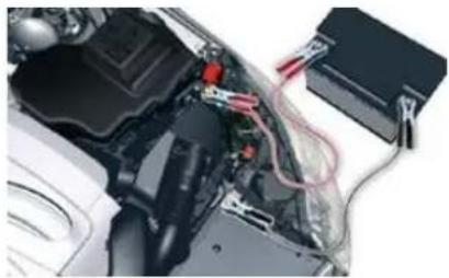
natural_image
Close-up of an automotive engine bay with visible wiring and components (no text or symbols)The battery is located under the bonnet.
For access to it:
open the bonnet using the interior release lever, then the exterior safety catch,
secure the bonnet stay,
remove the plastic cover to gain access to the two terminals,
unclip the fusebox to remove the battery, if necessary.
V6 HDi engine
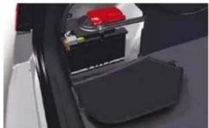
natural_image
Close-up of a car's front compartment showing battery, red switch, and rear door (no visible text or symbols)The battery is located in the boot under the left-hand wing trim.
For access to it:
open the boot,
open the flap and remove the battery.
Starting using another battery
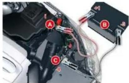
Lift the pins to remove the front left headlamp cover (V6 HDi engine).
Connect the red cable to the positive terminal (+) of the flat battery A, then to the positive terminal (+) of the slave battery B.
Connect one end of the green or black cable to the negative terminal (-) of the slave battery B.
V6 HDi engine: the positive terminal (-) is located under the red cover.
Connect the other end of the green or black cable to the earth point C on the broken down vehicle.
Operate the starter, let the engine run.
Wait until the engine returns to idle and disconnect the cables.
XI
PRACTICAL INFORMATION
Charging the battery using a battery charger
Disconnect the battery from the vehicle.
Follow the instructions for use provided by the manufacturer of the charger.
Reconnect starting with the negative terminal (-).
Check that the terminals and connectors are clean. If they are covered with sulphate (whitish or greenish deposit), remove them and clean them.

The batteries contain harmful substances such as sulphuric acid and lead. They must be
disposed of in accordance with regulations and must not, in any circumstances, be discarded with household waste.
Take used remote control batteries and vehicle batteries to an authorised collection point.

Do not disconnect the terminals while the engine is running.
Do not charge the batteries without disconnecting the terminals fi rst.
Do not touch the clips during the operation.
Do not lean over the batteries.
Disconnect the cables in the reverse order to connection, ensuring that they do not touch.
Before disconnecting the battery
Wait 2 minutes after switching off the ignition before disconnecting the battery.
Close the windows and the doors before disconnecting the battery.
Following reconnection of the battery
Following reconnection of the battery, switch on the ignition and wait 1 minute before starting to permit initialisation of the electronic systems. However, if slight malfunctions remain following this operation, contact a CITROËN dealer.
Referring to the corresponding section, you must yourself reinitialise:
- the remote control key,
- the glass panoramic roof blind,
- the GPS satellite navigation system.
It is advisable to disconnect the battery if the vehicle is to be left unused for more than one month.
PRACTICAL INFORMATION
ENERGY ECONOMY MODE
System which manages the duration of use of certain functions to conserve a sufficient level of charge in the battery.
After the engine has stopped, you can still use functions such as the audio and telematics system, windscreen wipers, dipped headlamps, courtesy lights, etc. for a maximum combined duration of thirty minutes.
Switching to economy mode
Once the thirty minutes are over, a message appears on the multi-function screen indicating that the vehicle has switched to economy mode and the active functions are put on standby.
If the telephone is being used at this time:
- it will be maintained for 5 minutes with radio-CD hands-free kit,
- it will be interrupted after 10 minutes with the MyWay audio-navigation system,
- you can complete your call with the NaviDrive system.
This period may be signifi cantly reduced if the battery charge is low.
Exiting economy mode
These functions are reactivated automatically next time the vehicle is driven.
In order to resume the use of these functions immediately, start the engine and let it run for a few minutes.
The time available will then be double the duration for which the engine was left running. However, this time will always be between five and thirty minutes.

A fl at battery prevents the engine from starting (refer to the corresponding paragraph).
PRACTICAL INFORMATION
TOWING THE VEHICLE
Procedure for having your vehicle towed or for towing another vehicle using a removable towing eye.
Access to the tools
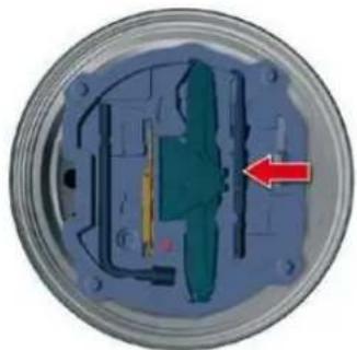
natural_image
Cross-sectional view of a mechanical component with internal structure and red arrow indicator (no text or symbols)The towing eye is installed in the jack box placed in the spare wheel.
For access to it:
open the boot,
raise the floor,
remove the towing eye from the jack box.
Towing your vehicle
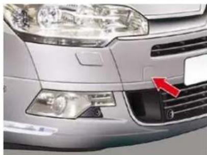
natural_image
Close-up of a silver car's front grille and dashboard, showing red arrow pointing to the grille (no text or symbols visible)On the front bumper, unclip the cover by pressing at the top.
Screw the towing eye in fully.
Attach the towing bar.
Switch on the hazard warning lamps on the towed vehicle.
Place the gear lever in neutral (position N on the automatic gearbox).
Failure to observe this special condition could result in damage to certain braking components and the absence of braking assistance the next time the engine is started.
Towing another vehicle
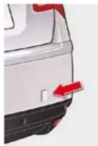
natural_image
Close-up of a car's rear bumper with red arrow indicating direction (no text or symbols)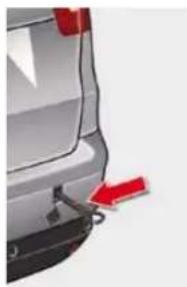
natural_image
Side view of a silver car trunk with a red arrow pointing to the side (no text or symbols visible)On the rear bumper, unclip the cover by pressing:
- on the right (Saloon),
- at the bottom (Tourer).
Screw the towing eye in fully.
Attach the towing bar.
Switch on the hazard warning lamps on the towed vehicle.
When towing with all four wheels on the ground, always use a towing bar.
When towing with only two wheels on the ground, always use professional lifting equipment.
When towing with the engine off, there is no longer any braking or steering assistance.
PRACTICAL INFORMATION
TOWING A TRAILER, A CARAVAN, ETC
Towbar suitable for the attachment of a trailer or caravan with additional lighting and signalling.
natural_image
Side view of a silver sedan car (no visible text or symbols)Your vehicle is primarily designed for transporting people and luggage, but it may also be used for towing a trailer.
We recommend the use of genuine CITROËN towbars and their harnesses that have been tested and approved from the design stage of your vehicle, and that the fi tting of the towbar is entrusted to a CITROËN dealer.
If the trailer is not fitted by a CITROEN dealer, it is imperative that it is fitted using the electrical pre-equipment installed at the rear of the vehicle, in accordance with the manufacturer's instructions.
Driving with a trailer subjects the towing vehicle to more significant stress and its driver must be particularly careful.
Driving advice
Distribution of loads
- Distribute the load in the trailer so that the heaviest items are as close as possible to the axle and the nose weight approaches the maximum permitted without exceeding it.
Air density decreases with altitude, thus reducing engine performance. Above 1 000 metres, the maximum towing load must be reduced by 10 % and so on for every 1 000 metres of altitude.
Refer to the "Technical Data" section for details of the weights and towing loads which apply to your vehicle.
Side wind
Take into account the increased sensitivity to side wind.
Cooling
Towing a trailer on a slope increases the temperature of the coolant.
As the fan is electrically controlled, its cooling capacity is not dependent on the engine speed.
To lower the engine speed, reduce your speed.
The maximum towing load on a long slope depends on the gradient and the ambient temperature.
In all cases, pay attention to the coolant temperature.

If the warning lamp and the STOP warning lamp come on, stop the vehicle and switch off the engine as soon as possible.
Braking
Towing a trailer increases the braking distance.
Tyres
Check the tyre pressures of the towing vehicle and of the trailer, observing the recommended pressures.
Lighting
Check the electrical lighting and signalling on the trailer.
The rear parking sensors will be de-activated automatically if a genuine CITROËN towbar is used.
PRACTICAL INFORMATION
ROOF BARS
The design of your vehicle requires the use of roof bars that are tested and approved by CITROËN, for your safety and to avoid damage to the roof and tailgate.
Regardless of the type of loading equipment to be transported on the roof (bicycle carrier, ski carrier...), it is imperative that you add transverse roof bars. Any securing or lashing to components other than the roof bars is strictly prohibited.
Recommendations
C. Distribute your load evenly, avoiding overloading on one side.
Arrange the heaviest part of the load as close as possible to the roof.
Anchor the load securely and draw attention to it if any part of it is overhanging.
Drive gently, as the vehicle will be more liable to the effects of side winds (vehicle stability may be altered).
Remove the roof bars as soon as they are no longer needed.
! Maximum load that can be distributed on the roof bars (for a loading height not exceeding 40 cm; except bicycle carrier): 80 kg.
If the height exceeds 40 cm, adapt your speed to the profile of the road to avoid damaging the roof bars and the fixings on the roof.
Please refer to national legislation in order to comply with the regulations concerning the transportation of objects which are longer than the vehicle.
PRACTICAL INFORMATION
VERY COLD PROTECTION
Adjustable device which prevents the intake of snow particles, which could obstruct the air filter.
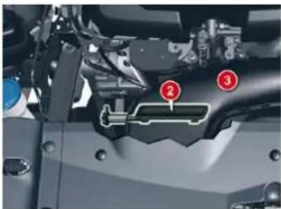
natural_image
Close-up of a mechanical component with numbered parts (2 and 3), no visible text or symbolsDiesel engine HDi 163 PEF
Normal position
The flap 2 is in a horizontal position in the air duct 3.
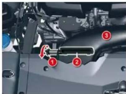
Snow position
Push and rotate the knob 1 by 90^ in the direction of the arrow in order to position the flap 2 in a vertical position in the air duct 3.
To return to the normal position, push the knob 1 then rotate in the opposite direction.
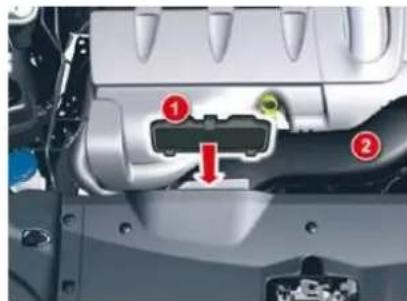
Diesel engine V6 HDi 240 PEF
Snow position
Slide the deflector 1 into the air duct 2 and clip in.
It is essential to remove the very cold protection:
- When the ambient temperature exceeds 10 °C.
- When driving at speeds of over 75 mph (approximately 120 km/h).
PRACTICAL INFORMATION
COLD CLIMATE SCRE
Removeable screen which prevents the accumulation of snow at the radiator cooling fan.
Fitting
Offer up the 2 sections of the snow guard to the upper and lower sections of the front bumper.
Press on the surround to clip in one by one the fixing clips.
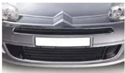
natural_image
Front view of a silver car with a white BMW logo and grille (no visible text or symbols)Before fi tting

natural_image
Front view of a silver car grille with red arrows pointing to the grille (no visible text or symbols)After fi tting
Remove
Using a screwdriver, lift it up to detach each fixing clip one by one.
It is essential to remove the snow guard:
- When the ambient temperature exceeds 10 °C'
- When towing,
- When driving at speeds of over 75 mph (approximately 120 km/h).
* According to country.
PRACTICAL INFORMATION

ACCESSORIES
A wide range of accessories and genuine parts is offered by the CITROËN network.
These accessories and parts have been tested and approved for reliability and safety.
They are all adapted to your vehicle and benefit from CITROEN's recommendation and warranty.
This product range is structured around 5 categories:
"Protection": anti-theft alarm, wheel anti-theft devices, stolen vehicle tracking system, breathalyser, first aid kit, warning triangle, high visibility jacket, dog guard, snow chains, nonskid covers, fog lamps kit, puncture repair kit, rear parking sensors...
"Comfort and leisure": mats *, boot tray, boot carpet, sun blinds, mini-bar, fragrance cartridges, roof bars, bicycle carrier, ski carrier, roof boxes, towbars, child seats and booster cushions...
"Navigation and communication": Bluetooth® hands-free kit, audio equipment, portable satellite navigation system, DVD player, auxiliary cable for connecting a portable MP3 player, USB Box, speakers...
*To avoid any risk of jamming of the pedals:
- ensure that the mat is positioned and secured correctly,
- never fit one mat on top of another.
"Personalisation": seat covers, alloy wheels, wheel trims, mud flaps...
"Accessories": windscreen wash fluid, interior and exterior cleaning and maintenance products, body-work touch-up aerosol and pen...
Depending on the country in which the vehicle is sold, it may be compulsory to have a high visibility safety jacket, warning triangle and spare bulbs available in the vehicle.
The fitting of electrical equipment or accessories which are not recommended by CITROËN may result in a failure of your vehicle's electronic system and excess consumption.
Please note this specific warning. You are advised to contact a representative of the marque to be shown the range of recommended equipment and accessories.
TECHNICAL DATA
| MODELS: | ENGINES AND GEARBOXES | ||||
| Model codes:RD... RW... | 6FYC | RFJF | RFJC/FF | 5FV-5FN | XFVJ |
| PETROL ENGINES | 1.8 litre 16V127 hp | 2 litre 16V143 hp | Biofl ex 2 litre16V 143 hp | 1.6 litre 156 hp | 3 litre V6 24V215 hp |
| Cubic capacity (cc) 1 749 1 997 | 1 997 1 598 | 2 946 | |||
| Bore x stroke (mm) 82.7 x 81.4 | 85 x 88 85 x 88 | 77 x | 85.8 87 x 82.6 | ||
| EU standard maximum power (kW) | 92 | 103 | 103 | 115 | 155 |
| Maximum power engine speed (rpm) | 6 000 | 6 000 6 000 | 6 000 6 000 | ||
| EU standard maximum torque (Nm) | 170 | 200 | 200 | 240 | 290 |
| Maximum torque engine speed (rpm) | 3 750 | 4 000 4 000 | 1 400 3 750 | ||
| Fuel | Unleaded | Unleaded | Unleaded/E85 | Unleaded | Unleaded |
| Catalytic converter | Yes | Yes | Yes | Yes | Yes |
| GEARBOXES | Manual(5-speed) | Auto.(4-speed) | Manual(5-speed) | Manual(6-speed) | Auto.(6-speed) |
| OIL CAPACITIES (in litres) | |||||
| Engine (with filter replacement) | 5 | 5 | - | 4.2 | 4.75 |
| Gearbox - Final drive | - | - | - | - | - |
TECHNICAL DATA
| MODELS: | ENGINES AND GEARBOXES | ||||
| Model codes:RD... RW... | 9HZC9HZC/1 | RHF8 | RHH-RHE | X8ZA | |
| DIESEL ENGINES | 1.6 litre HDi110 hp | 2 litre HDi140 hp | 2 litre HDi 163 hp | 3 litre V6 HDi240 hp | |
| Cubic capacity (cc) 1 560 1 997 | 1 997 2 993 | ||||
| Bore x stroke (mm) 75 x 88.3 | 85 x 88 85 x 88 | 84 x 90 | |||
| EU standard maximum power (kW) | 80 103 | 120 | 177 | ||
| Maximum power engine speed (rpm) | 4 000 | 4 000 3 750 | 3 800 | ||
| EU standard maximum torque (Nm) | 240 | 320 | 340 | 450 | |
| Maximum torque engine speed (rpm) | 1 750 | 2 000 2 000 | 1 600 | ||
| Fuel | Diesel | Diesel | Diesel | Diesel | |
| Catalytic converter | Yes | Yes | Yes | Yes | |
| Particle emission filter (PEF) | Yes | Yes | Yes | Yes | |
| GEARBOXES | Manual(5-speed) | Manual(6-speed) | Manual(6-speed) | Auto.(6-speed) | Auto.(6-speed) |
| OIL CAPACITIES (in litres) | |||||
| Engine (with filter replacement) | 3.75 | 5.25 | - | - | |
| Gearbox - Final drive | 1.9 | - | - | - | |
XII
TECHNICAL DATA
| WEIGHTS AND TOWED LOADS (SALOON) in kg | |||||
| Petrol engines | 1.8 litre VTi 16V 127 hp | 2 litre 16V 143 hp | Biofl ex 2 litre 16V 143 hp | 1.6 litre 156 hp | 3 litre V6 24V 215 hp |
| Gearboxes | Manual | Auto. | Auto. | Manual | Auto. |
| Model codes: RD... | 6FYC | RFJF | RFJC/FF | 5FV-5FN | XFVJ |
| - Unladen weight | 1 510 | 1 583 | 1 521 | 1 471 | 1 725 |
| - Kerb weight | 1 585 | 1 658 | 1 596 | 1 546 | 1 800 |
| - Gross vehicle weight (GVW) | 2 015 | 2 090 | 2 063 | 2 065 | 2 230 |
| - Gross train weight (GTW) | 3 315 | 3 590 | 3 563 | 3 565 | 3 630 |
| - Braked trailer (within GTW limit) on a 10 % or 12 % gradient | 1 300 | 1 500 | 1 500 | 1 500 | 1 400 |
| - Braked trailer * (with load transfer within GTW limit) | 1 530 | 1 720 | 1 720 | 1 730 | 1 650 |
| - Unbraked trailer | 750 | 750 | 750 | 750 | 750 |
| - Recommended nose weight | 62 | 69 | 69 | 70 | 66 |
* The weight of the braked trailer can be increased, within the GTW limit, on condition that the GVW of the towing vehicle is reduced by the same amount; warning, towing with a lightly loaded towing vehicle may have an adverse effect on its road holding.
The GTW and towed load values indicated apply up to a maximum altitude of 1,000 metres; the towed load mentioned must be reduced by 10% for each additional 1,000 metres of altitude.
The speed of a towing vehicle must not exceed 100 km/h (approx. 60 mph) (comply with the legislation in force in your country).
High ambient temperatures may result in a reduction in the performance of the vehicle in order to protect the engine; when the ambient temperature is higher than 37 °C , limit the weight towed.
XII
TECHNICAL DATA
| WEIGHTS AND TOWED LOADS (SALOON) in kg | |||||
| Diesel engines | 1.6 litre HDi 110 hp | 2 litre HDi 140 hp | 2 litre HDi 163 hp | 3 litre V6 HDi 240 hp | |
| Gearboxes | Manual | Manual | Manual | Auto. | Auto. |
| Model codes: RD... | 9HZC 9HZC/1 | RHF8 | RHH-RHE | X8ZA | |
| - Unladen weight 1 485 1 608 | 1 563 1 609 | 1 766 | |||
| - Kerb weight 1 560 1 683 | 1 638 1 684 | 1 841 | |||
| - Gross vehicle weight (GVW) | 2 045 2 155 | 2 156 2 190 | 2 276 | ||
| - Gross train weight (GTW) | 3 145 | 3 755 3 656 | 3 290 3 676 | ||
| - Braked trailer (within GTW limit) on a 10 % or 12 % gradient | 1 100 | 1 600 | 1 500 | 1 100 | 1 400 |
| - Braked trailer * (with load transfer within GTW limit) | 1 370 1 | 820 1 740 | 1 390 1 650 | ||
| - Unbraked trailer | 750 | 750 | 750 | 750 | |
| - Recommended nose weight | 55 | 73 | 70 | 57 | 67 |
* The weight of the braked trailer can be increased, within the GTW limit, on condition that the GVW of the towing vehicle is reduced by the same amount; warning, towing with a lightly loaded towing vehicle may have an adverse effect on its road holding.
The GTW and towed load values indicated apply up to a maximum altitude of 1,000 metres; the towed load mentioned must be reduced by 10 % for each additional 1,000 metres of altitude.
The speed of a towing vehicle must not exceed 100 km/h (approx. 60 mph) (comply with the legislation in force in your country).
High ambient temperatures may result in a reduction in the performance of the vehicle in order to protect the engine; when the ambient temperature is higher than 37^ , limit the weight towed.
TECHNICAL DATA
| WEIGHTS AND TOWED LOADS (TOURER) in kg | |||||
| Petrol engines | 1.8 litre VTi 16V 127 hp | 2 litre 16V 143 hp | Biofl ex 2 litre 16V 143 hp | 1.6 litre 156 hp | 3 litre V6 24V 215 hp |
| Gearboxes | Manual | Auto. | Manual | Manual | Auto. |
| Model codes: RW... | 6FYC | RFJF | RFJC/FF | 5FV-5FN | XFVJ |
| - Unladen weight | 1 549 | 1 619 | 1 578 | 1 503 | 1 761 |
| - Kerb weight | 1 624 | 1 694 | 1 653 | 1 578 | 1 836 |
| - Gross vehicle weight (GVW) | 2 154 | 2 224 | 2 183 | 2 167 | 2 366 |
| - Gross train weight (GTW) | 3 454 | 3 724 | 3 683 | 3 667 | 3 666 |
| - Braked trailer (within GTW limit) on a 10 % or 12 % gradient | 1 300 | 1 500 | 1 500 | 1 500 | 1 300 |
| - Braked trailer * (with load transfer within GTW limit) | 1 600 1 800 | 1 790 1 790 | 1 600 | ||
| - Unbraked trailer | 750 | 750 | 750 | 750 | 750 |
| - Recommended nose weight | 64 | 72 | 72 | 73 | 68 |
* The weight of the braked trailer can be increased, within the GTW limit, on condition that the GVW of the towing vehicle is reduced by the same amount; warning, towing with a lightly loaded towing vehicle may have an adverse effect on its road holding.
The GTW and towed load values indicated apply up to a maximum altitude of 1,000 metres; the towed load mentioned must be reduced by 10 % for each additional 1,000 metres of altitude.
The speed of a towing vehicle must not exceed 100 km/h (approx. 60 mph) (comply with the legislation in force in your country).
High ambient temperatures may result in a reduction in the performance of the vehicle in order to protect the engine; when the ambient temperature is higher than 37^ , limit the weight towed.
TECHNICAL DATA
| WEIGHTS AND TOWED LOADS (TOURER) in kg | |||||
| Diesel engines | 1.6 litre HDi 110 hp | 2 litre HDi 140 hp | 2 litre HDi 163 hp | 3 litre V6 HDi 240 hp | |
| Gearboxes | Manual | Manual | Manual | Auto. | Auto. |
| Model codes: RW... | 9HZC 9HZC/1 | RHF8 | RHH-RHE | X8ZA | |
| - Unladen weight 1 573 1 655 | 1 595 1 642 | 1 802 | |||
| - Kerb weight 1 612 1 730 | 1 670 1 717 | 1 877 | |||
| - Gross vehicle weight (GVW) | 2 178 | 2 276 2 238 | 2 286 2 373 | ||
| - Gross train weight (GTW) | 3 178 | 3 776 3 638 | 3 286 3 676 | ||
| - Braked trailer (within GTW limit) on a 10 % or 12 % gradient | 1 000 | 1 500 | 1 400 | 1 000 | 1 300 |
| - Braked trailer * (with load transfer within GTW limit) | 1 300 1 | 800 1 670 | 1 290 1 600 | ||
| - Unbraked trailer | 750 | 750 | 750 | 750 | |
| - Recommended nose weight | 52 | 72 | 67 | 53 | 64 |
* The weight of the braked trailer can be increased, within the GTW limit, on condition that the GVW of the towing vehicle is reduced by the same amount; warning, towing with a lightly loaded towing vehicle may have an adverse effect on its road holding.
The GTW and towed load values indicated apply up to a maximum altitude of 1,000 metres; the towed load mentioned must be reduced by 10 % for each additional 1,000 metres of altitude.
The speed of a towing vehicle must not exceed 100 km/h (approx. 60 mph) (comply with the legislation in force in your country).
High ambient temperatures may result in a reduction in the performance of the vehicle in order to protect the engine; when the ambient temperature is higher than 37 °C , limit the weight towed.
XII
TECHNICAL DATA
DIMENSIONS (IN MM)
Exterior (Saloon)
| A | 2 815 |
| B | 1 054 |
| C | 910 |
| D | 4 779 |
| E | 1 586 |
| F | 2 096 |
| G | 1 557 |
| H | 1 860 |
| I* | 1 451 |
* Without roof bars.
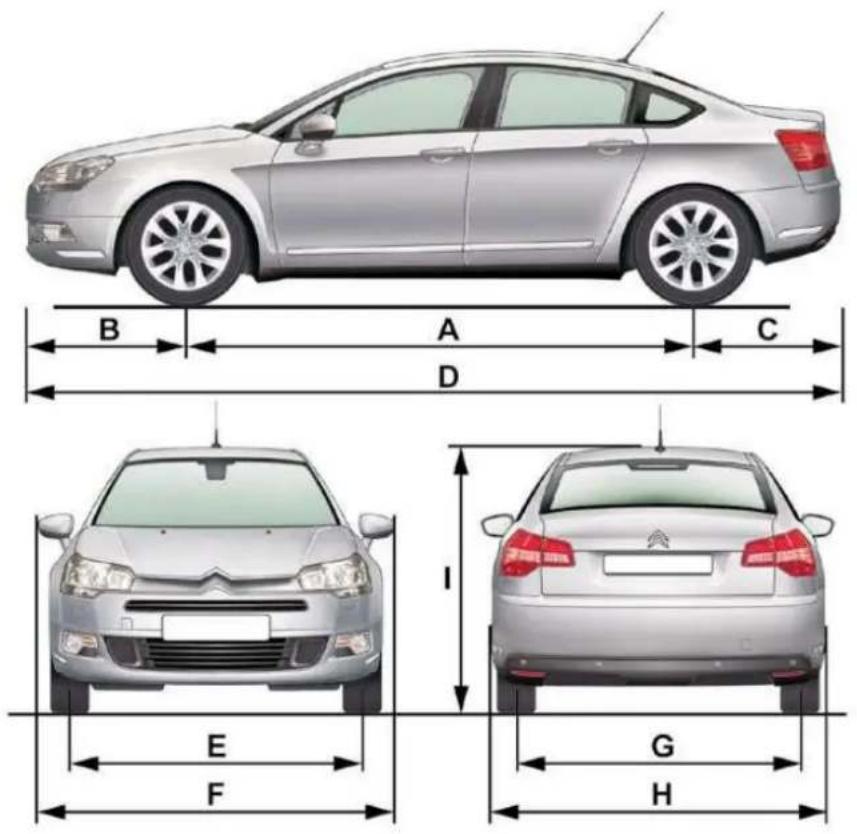
TECHNICAL DATA
Interior (Saloon)
| A | 1 030 |
| B | 1 115 |
| C | 566 |
| D | 504 |
| E | 1 040 |
| F | 1 705 |
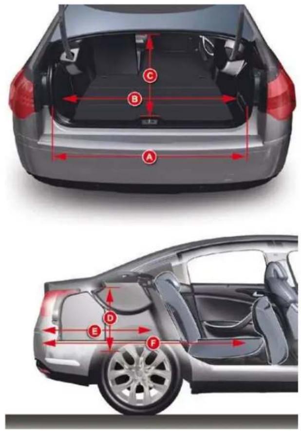
TECHNICAL DATA
Exterior (Tourer)
| A | 2 815 |
| B | 1 054 |
| C | 959 |
| D | 4 829 |
| E | 1 586 |
| F | 2 096 |
| G | 1 557 |
| H | 1 860 |
| I* | 1 479 |
* Without roof bars.
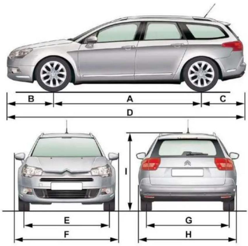
TECHNICAL DATA
Interior (Tourer)
| A | 1 060 |
| B | 1 115 |
| C | 510 |
| D | 851 |
| E | 1 058 |
| F | 1 723 |
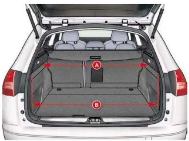
natural_image
Top-down view of a white car showing rear cargo bay with labeled parts A and B (no text or symbols beyond labels)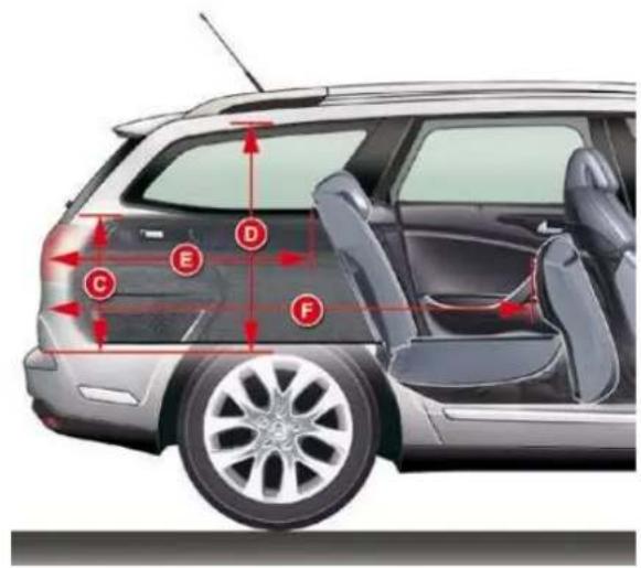
XII
TECHNICAL DATA
IDENTIFICATION MARKINGS
Various visible markings for identifi cation of the vehicle.
The vehicle identification number (VIN) is also indicated on the registration document.
All genuine CITROËN replacement parts are available exclusively within the dealer network.
For your safety and in order to remain within the terms of the warranty, you are advised to use only CITROËN replacement parts.
A. VIN plate
On the left hand centre door pillar.
- EU type approval number.
- Vehicle Identification Number (VIN).
- Gross vehicle weight.
- Gross train weight.
- Maximum weight on front axle.
- Maximum weight on rear axle.
B. VIN stamped on body
C. VIN on dashboard
D. Paint colour code and tyre reference
Tyre pressures
On the left hand door centre pillar.
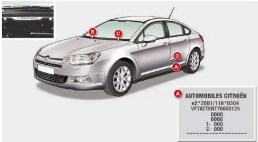
Observe the tyre pressures indicated by CITROËN.
Check the tyre pressures regularly, when cold.
Never deflate a warm tyre.
When changing tyres, it is essential to use the sizes recommended for your vehicle.
EMERGENCY OR ASSISTANCE CALL
EMERGENCY CAL

In an emergency, press this button for more th 2 seconds. Flashing of the green diode and a voic message confi rm that the call has been made to th CITROËN Emergency team
Pressing this button again immediately cancels the request. The gre diode switches off
The green diode remains on (without flashing) when communication established. It switches off at the end of communication
This call is dealt with by the CITROEN Emergency team which receiving information from the vehicle and can send a detailed alert to the appropriate emergency services. In countries in which the team is an operational, or when the locating service has been expressly refuse the call is dealt with directly by the emergency services (112) without the vehicle location

If an impact is detected by the airbag ECU, and independently of a triggering of the airbags, an emergency call is made automatically.
* This service is subject to conditions and availability. Consult a CITROEN dealer
ASSISTANCE CAL

Press this button for more than 2 seconds to request assistance if the vehicle breaks down A voice message confirms that the call has been made
Pressing this button again immediately cancels the reque. The cancellation is confirmed by a voice message.
When the ignition is switched on, the gre indicator lamp comes on for 3 seconds indicating that the system is operating correctly

If the orange indicator lamp flashes: there a system malfunction If the orange indicator lamp is lit continuous, the backup battery must be replaced In both cases, consult a CITROËN dealer.
EMERGENCY OR ASSISTANCE CALL using NaviDrive
EMERGENCY CALL

ASSISTANCE CALL

Warning - the emergency call and the services are only active if the internal telephone is used with a valid SIM card. With Bluetooth telephone and without a SIM card, these services are no operational.

In an emergency, press the SOS button until an audit signal is heard and a "Confir rmation/Cancellation screen is displayed (if valid SIM card inserted) A call is made * to t CITROEN Emergency team which receives locating information from the vehicle and can send a detailed alert to the relevar emergency services In countries in which the team is not operational, c when the locating service has been expressly rejected the call is sent to the emergency services (112

If an impact is detected by the airbag control unit, and independen of the triggering of any airbags, an emergency call is mac automatically The message "Deteriorated emergency call" associated with flashing of the orange indicator lamp indicates a malfunction Consult a CITROËN dealer
* This service is subject to conditions and availability. Consult a CITR dealer

Press this button for access to CITROËN services
Select "Customer call" to request any information about the CITROËN marque.
CUSTOMER CALI
Select CITROEN Assistance" to make a breakdown assistance call
CITROËN ASSISTANCI
* These services and options are subject to conditions and availability.
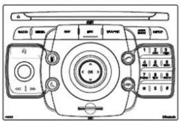
NaviDrive 3D
MULTIMEDIA AUDIO EQUIPMENT/BLUETOOTH TELEPHON
GPS EUROP

The NaviDrive 3D is protected in such a way that will only operate in your vehicle. If it is to be installed in another vehicle, contact a CITROEN dealer fc configuration of the system

For safety reasons, it is imperative that the driver carri out operations which require prolonged attention while the vehicle is stationary When the engine is switched off and to prevent discharging of the battery, the NaviDrive 3D switches of following the activation of the Energy Economy mode

Certain functions described in this handbook will becor available during the course of the year.
CONTENT:
• 01 First steps p. 209
- 02 Voice commands: steering mounted controls p. 2
• 03 General operation p. 214
• 04 Navigation - Guidance p. 218
• 05 Traffic information p. 227
• 06 Radio p. 229
• 07 Music media players p. 230
• 08 Using the telephone p. 235
• 09 Configuration p. 239
• 10 Screen menu map p. 240
- Frequently asked questions p. 244
01 FIRST STEPS
NaviDrive 3D CONTROL PANEL
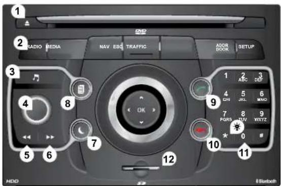
Short press: clears the last character.
Long press: activates voice recognition.
1 CD eject.
2 RADIO: access to the "Radio" Menu. Display the list of stations in alphabetical order (FM waveband) or frequency order (AM waveband).
MEDIA: access to the "Media" Menu (Audio CD, Jukebox, External Device). Display the list of tracks. Change of source.
NAV: access to the "Navigation" Menu and display of the last destinations.
ESC: abandon the operation in progress. Long press: return to the main display.
TRAFFIC: access to the "Traffic" Menu (function described in detail in sections 02 and 10)
ADDR BOOK: access to the "Address book" Menu (function described in detail in section 10).
SETUP: access to the "SETUP" Menu (configuration) (function described in detail in sections 02 and 10) Long press: GPS coverage.
- Audio settings (Balance/Fader, Bass/Treble, Musical Ambience...).
4 Volume adjustment (each source is independent, including message and navigation alert) Long press: reinitialisation of the system Short press: mute.
5 Automatic search for a radio station on a lower frequency. Selection of the previous CD or MP3 track
- Automatic search for a radio station on a higher frequency. Selection of the next CD or MP3 track
- Normal display or black screen.
- Selection of the successive display on the screen of "MAP", "NAV" (if navigation is in progress)"TEL" (if a conversation is in progress)"RADIO" or "MEDIA" currently being played.
- PICK UP: access to the "Phone" menu. With Bluetooth connection, accept an incoming call.
- HANG UP: access to the "Phone" menu. Hang up the current call or refuse an incoming call, with Bluetooth connection.
- Entering of numbers or letters on the alpha-numeric keypad, pre-selection of 10 radio frequencies.
- SD card reader.
01 FIRST STEPS NaviDrive 3D NAVIGATO
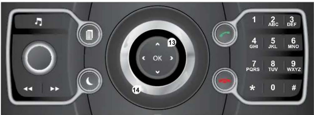
13 OK: confirmation of the highlighted item on the screen
- 4-direction navigator: press to the left/right.
When the "RADIO" screen is displayed: selection of the previous/next frequency
When "MEDIA" is displayed: selection of the previous/next track
When "MAP" or "NAV" is displayed: horizontal movement of the map.
- 4-direction navigator: press up/down.
When "RADIO" is displayed: selection of the previous/next radio station on the list
When the "MEDIA" screen is displayed: selection of the MP3 directory
When "MAP" or "NAV" is displayed: vertical movement of the map.
Switch to the next or previous page of a menu. Movement on the virtual keypad displayed.
- Rotation of the ring:
When the "RADIO" screen is displayed; selection of the previous/next radio station on the list
When the "MEDIA" screen is displayed: selection of the previous/next CD or MP3 track
When "MAP" or "NAV" is displayed: front/rear map zoom.
Movement of the menu selection cursor.
02 VOICE COMMANDS AND STEERING MOUNTED CONTRO
C5 STEERING MOUNTED CONTROL

- Successive presses: "Black Panel" mode - black screen (night driving)
- Short press to make a telephone call. Pick up/Hang up. Access the telephone menu. Display the call list. Long press to reject an incoming call.
Short press: activate the voice recognitc Long press: repeat the current navigatic instruction
Successive presses: provides access the Radio and Media screen according to the current display

- Rotation: provides access to the short-cut menus according to the display on the screen. Short press: confirm the choice displayed on screen. Long press: return to the main menu.
- Short press: abandon the current operation. Reject an incoming telephone call. Long press: return to the initial display.
- Menu: provides access to the main menu.
- VOL +: volume increase.
- VOL -: volume decrease.
- Successive presses: mute/restore sound.
- Short press: Radio: higher frequency.
Music players: next track.
Long press for fast play.
1 Short press: Radio: lower frequency. Music players: previous track. Long press for fast play. - Short press: display the list of radio frequencies available or the list of tracks, albums, directories. Long press: update the list of stations received.
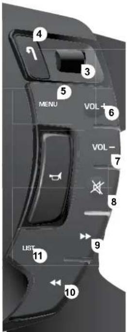
02 VOICE COMMANDS AND STEERING WHEEL CONTROL
VOICE COMMANDS - VOIC RECO. INITIATIO


Before using the system for the first time, you are advised to listen to, say and repeat the instructions for use

Press the SETUP button ar select the "Language & Speech function. Turn the ring and select "Voice control". Activate the voic recognition Select "Tutorial"

The phrases to be spoken according to the context a indicated in the tables below Speak and NaviDrive 3D acts


Long press on this button or press on tl end of the lighting stalk: activates the voic recognition.
| CONTE) | SA | ACTIO |
| GENER# | Help address booHelp voice contrcHelp mediHelp navigationHelp telephoneHelp radicCanceCorrector | Access to the address book helAccess to the voice reco helAccess to the media management helAccess to the guidance, navigation helAccess to the telephone helAccess to the radio helTo cancel a voice command which is in progres:Request to correct the last voice recognition carriedClea |
| RADI | Select stationStationfrom the RADIO lisSelect a radio station using its RDS descripticRead out station lisEnter frequencySelect wave bandAMFlvTA orTA or | Select a radio station:Select a radio station using its RDS descripticfrom the RADIO lisListen to the list of stations availablListen to the frequency of the current radio staticChoose the frequency waveband (AM or FIChange the frequency waveband to AIChange the frequency waveband to FIActivate the Traff ic Info (TDeactivate the Traff ic In |
| NAVIGATIC | Destination inputVoice advice ofVoice advice orSave address:Start guidancAbort guidancNavigate entr:POI Search | Command to enter a new destination addresDeactivate the spoken guidance instructiorActivate the spoken guidance instructiorSave an address in the address bocStart guidance (once the address has been enteredStop the guidancStart guidance to a file in the address boStart guidance to a point of interest |
02 VOICE COMMANDS AND STEERING WHEEL CONTROL
VOICE COMMANDS - VOIC RECO. INITIATION

| CONTEX | SA | ACTIOI |
| MED | Medi:Select medi:Single slcJukebo:USEExternal devici:SD-CarrTrack <1 - 1 000Folder <1 - 1 000 | Select the MEDIA sourcChoose a sourcSelect the CD player sourcSelect the Jukebox sourcSelect the USB reader sourcSelect the audio AUX input sourcSelect the SD card sourcSelect a specifi c trac(number between 1 and 1 000) on the active MEDIISelect a Folde(number between 1 and 1 000) on the active MEDII |
| TELEPHON | Phone men!Enter numbePhone booDiaSave numbeAcceptRecep | Open the Telephone MenEnter a telephone number to be calleOpen the phone boolMake a calSave a number In the phone bocAccept an incoming caRefuse an incoming ca |
| ADDRESS BOC | Address book menCall | Open the address booCall fi le using its descriptionas describer the address bookStart guidance to an address in the address boc using its description |
DISPLAY ACCORDING TO THE CONTEXT
Press the MODE button several times in succession to gain access to the following displays:
(If a conversation is in progress
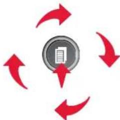
flowchart
graph TD
    A["Central Circle"] --> B["Arrow Left"]
    B --> C["Arrow Right"]
    C --> D["Arrow Down"]
    D --> E["Arrow Up"]
    E --> A
    style A fill:#99ccff,stroke:#333
    style B fill:#ccc,stroke:#333
    style C fill:#ccc,stroke:#333
    style D fill:#ccc,stroke:#333
    style E fill:#ccc,stroke:#333
FULL SCREEN MA
NAVIGATION
(If guidance is in progress
SETUI
access to the "SETUP" Menu: system language * a voice functions *, voice initialisation (section 09), da and time *, display, unit and system paramete
* Available according to mod

TRAFFIC
access to the Traffic Menu: display of the current traffic alerts
MEDI
"DVD-audio" menu "DVD-Video" meni

Long press: access to the GPS coverage and to the demonstration. For maintenance of the screen, the use of a soft, non-abrasive clc (spectacles cloth) is recommended, without any additional product.

For a detailed global view of the menus available, refer the "Screen menu map" section of this handbook.
DISPLAY ACCORDING TO THE CONTEXT


Pressing OK gives access to short-cut menus according to the display on the screen.
NAVIGATION (IF GUIDANCE IS IN PROGRESS)

ABORT GUIDANCI
REPEAT ADVICI
BLOCK ROA

UNBLOCK
MORE
LES:
CALCULATI
ZOOM/SCROLI
BROWSE ROUTE
ROUTE INFO

SHOW DESTINATION
TRIP INFO
Route typ
Avoli
Satellite
Stopover

BROWSE ROUTE

ZOOM/SCROLI

VOICE ADVICI

ROUTE OPTIONS

RECALCULATI

ELEPHONE

END CALI

HOLD CALI

DTMF-TONE:

PRIVATE MODI
MICRO OFF
MUSIC MEDIA PLAYER:

IA
PLAY OPTION:

NORMAL ORDER

RANDOM TRACK

SCAN

SELECT MEDIA
RADIC

IN FM MOD

TA

RDS

AM

IN AM MOD

FN
DISPLAY ACCORDING TO THE CONTEX

FULL SCREEN MAI
ABORT GUIDANCE/RESUME GUIDANC
1 SET DESTINATION/ADD STOPOVE
POIS NEARB'
POSITION INFO
OPTION!
3 Navigate to
Dia
Save position
Zoom/Scrol
MAP SETTING:
2D MAP
2.5D MAF
3DMAF
NORTH UF
HEADING UI
ZOOM/SCROLI
AUDIO DVD (LONG PRESS
1 STOF
GROUP
Group 1.2/1
2 PLAY OPTION
Normal order/Random track/Scan
1 TA
SELECT MEDIA
VIDEO DVD (LONG PRESS
PLA
, STOP
2 DVD MENU:
DVD men
3 DVD top menu
List of title:
3 List of chapter:
DVD OPTION:
Audic
Subtitles
Angli
Examples

- the map setting which allows the map to be displayed flat, in perspective or in 3D.
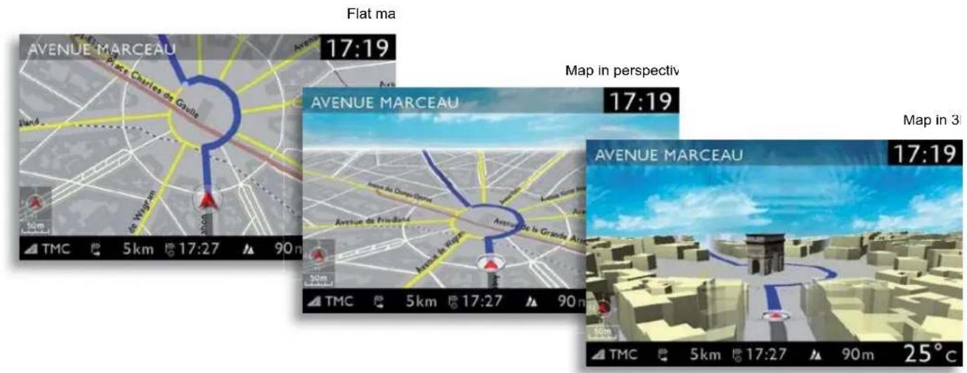
- configuration of the system by means of voice commands.

04 NAVIGATION - GUIDANCI
SELECTING A DESTINATION
The "NAVIGATION" voice commands are listed in section 09 During guidance, a long press on the end of the lighting staik repeats the last guidan instruction.
1
Press the NAV butto
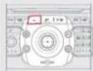
4
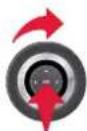
Select the "Address input" function and press OK to confirm
ADDRESS INPUT
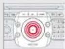
#
The list of the last 20 destinations appears under the navigation Menu function
5
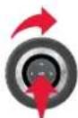
Once the country has been select to turn the ring and select the town function. Press OK to confirm
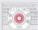
2
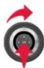
Press the NAV button again or select the Navigation Menu function and press OK to confirm
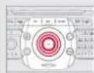
6
Select the letters of the town one by confi rming each time by pressing (
3
Select the "Destination input" function and press OK to confirm
DESTINATION INPU
#
A pre-set list (by entering the first few letters) of the towns in country selected can be accessed via the LIST button on the virtu keypad.
04 NAVIGATION - GUIDANCI

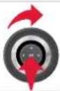
Turn the ring and select OI Press OK to confi rr
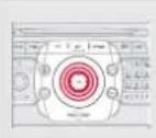

To speed up the process, the post code can be entered directly at selecting the "Postal code" function Use the virtual keypad to enter the letters and digit

Repeat steps 5 to 7 for the "Street and "House number" functions

Select the "Save to address book" function to record the addre entered in a directory fi le. Press OK to confi rm the selectic The NaviDrive 3D permits the recording of more than 4 000 conta fi les

To delete a destination; from steps 1 to 3, select "Choose from I destinations" A long press on one of the destinations displays a list of actions from which you can select
DELETE ENTRY
DELETE LIST
It is possible to scroll the map using the 4-direction navigator. It is possible to select its orientation via the short-cut menu of the "Full screen map". Press OK then select "Map Settings" and confirm

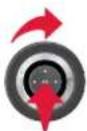
Then select "Start route guidance and the press OK to confirm
START ROUTE GUIDANCI
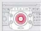

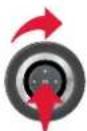
Select the route typ "Fast route", "Short route", c "Optimized route" and press OK to confirm
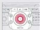

Select the road with the colo corresponding to the route chosen and press OK to confirm and sta guidance.

It is also possible to select a destination via "Choose from ad book" or "Choose from last destinations", by selecting a junction, a centre, geographic coordinates, or directly on the "M:
CHOOSE FROM ADDRESS BOOK
CHOOSE FROM LAST DESTINATION
04 NAVIGATION - GUIDANCI
ROUTE OPTION
When the map is displayed on the screen, you can select "Map Settings" then "2D Map/2.5D M 3D Map/North Up/Heading Up". The display of buildings in 3D mode depends on the progress in town mapping.
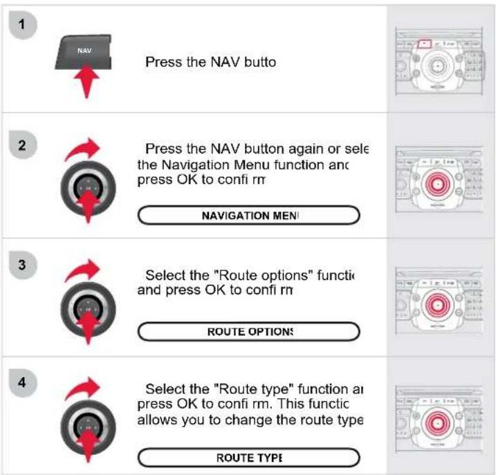
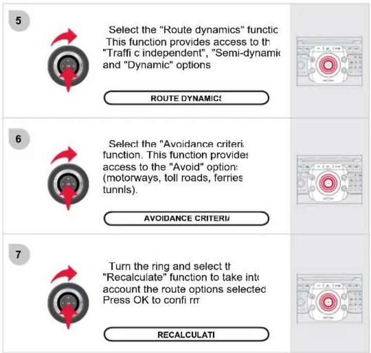
04 NAVIGATION - GUIDANCI
ADDING A STOPOVE
Stopovers can be added to or deleted from the route once the destination has been selected.
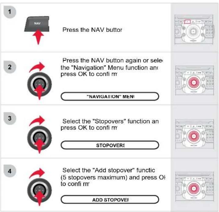
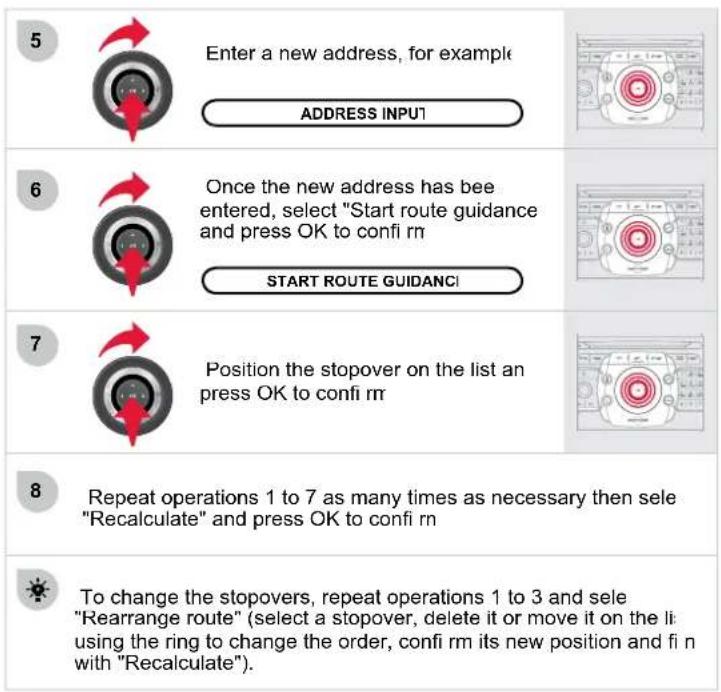
04 NAVIGATION - GUIDANCI
SEARCHING FOR POINTS OF INTERES (POI)
The points of interest (POIs) indicate all of the service locations in the vicinity (hotels, various businesses, airports...)
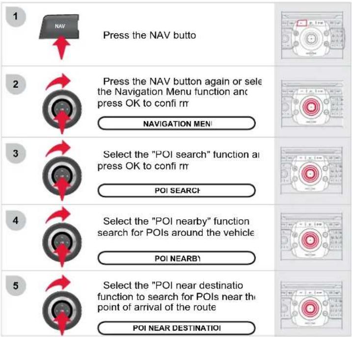
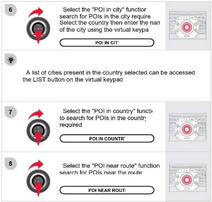
This service only operates with a SIM card from a French, German or Italian service provider
! The SIM card must be inserted in the support located in the glove. The system does not operate with the Bluetooth connectic
! SIM cards the numbers of which have been the subject of a chan of service provider are not compatible with this service
1 To access the registration site, go to www.citroen.fr then activate account with the registration confirmation ema
2 Register the vehicle and choose the identifier, which will be used to send POIs from Google Maps
3 Activate the service on your NaviDrive 3D in accordance with I operating procedure downloaded from the internet site It may take a few minutes for the Google Maps menu to appear.
In order to activate the service, the SIM card used must be it declared on the Internet site during registration Once the service has been activated, you can change SIM card service provider.
Find your destinations on Google Maps then let CITROËN guide yo
US
Search for a POI on http://maps.google.fr. Select it and click on "se Select "vehicle" and "CITROEN" then enter the identifi er chos Click on "send"
Only the Google Maps results symbolised by a red icon can be set to the NaviDrive 3D system
The "Notes" fi eld is not ser
2
Press this button then select Google Maps and confi by pressing OK.
An automatic call is triggered to a voice mail for receipt of the POI.
3 Press on "ADDR BOOK" and select "My Addresses" to display list of POIs received You can then start guidance, call the POI or display it on the map.
This service is free, with the exception of the cost of 1 communication - 2 SMS and 1 call for activation. 1 call for each receipt of a POI (approximately 30 seconds).
This icon appears when several PO
are grouped together in the same area Zooming in on this icon shows details o
the POIs

LIST OF PRINCIPAL POINTS OF INTEREST (PO

Service station
LPG station
Garage
CITROËN
Motor racing circuit
Covered car park
Car park
Rest area
Hotel
Restaurant
Refreshment area
Picnic area
Cafeteria

Airport
Railway station
Bus station
Port
Industrial estate
Supermarket
Bank
Vending machine
Tennis court
Swimming pool
Golf course
Winter sports resort
Theatre

Cinema
Camp site
Theme parks
Hospital
Pharmacy
Police station
School
Post office
Museum
Tourist information
Automatic speed camera*
Red light camera*
Risk area*
* According to availability in the co
Download the "Risk areas POIs" update fi le onto SD card or USB stick from the Internet. This service available on www.citroen.fr or www.citroen.co.ul
i
The files must be copied to the root on the chosen media
2
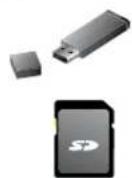
Insert the medium (SD card or USB stick) contain the POI database into the system's SD card reader of USB reader
3
Press NAV, select Navigation Mer then "Settings", then "Update personal POI"
NAVIGATION MEN!
SETTING:
UPDATE PERSONAL PO
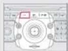
4
Select the medium ("USB" or "SL Card") used and press OK
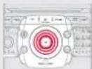
5
Successful downloading is confirmed by a messa
6
The system restart
i
The Risk Areas POIs version is available on the SETUP\System menu.
04 NAVIGATION - GUIDANCI
SPOKEN INSTRUCTION SETTING
1
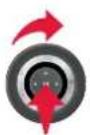
When the navigation is displayed (the screen, press OK then select or deselect "Voice advice" to activate or deactivate the spoken guidance instructions
Use the volume button to adjust th volume.
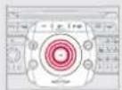
i
The volume of the Risk Areas POIs alert can only be adjusted during this type of alert
POINTS OF INTEREST AND RISK AREA SETTINGS
1
Press the NAV buttc
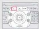
2
Press the NAV button again or select the Navigation Menu function and press OK to confirm
NAVIGATION MENU
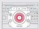
3
Select the "Settings" function ar press OK to confirm
SETTINGS
4
Select the "POI categories on Ma function to select the POIs to be displayed on the map by default
POI CATEGORIES ON MA
5
Select "Set parameters for risk area to gain access to the "Display or map", "Visual alert" and "Sound alert functions.
SET PARAMETERS FOR RISK AREA
05 TRAFFIC INFORMATION
CONFIGURE THE FILTERING AND DISPLAYING OF THE TMC MESSAGES
The TMC (Traffic Message Channel) messages provide information relating to traffic and weather conditions, received in real time and transmitted to the driver audibly and visually on the navigation map. The guidance system can then suggest an alternative rout
1

Press the TRAFFIC butto
The list of TMC messages appears under the Traffic Menu sorter order of proximity
2
Press the TRAFFIC button again select the Traffi c Menu function ar press OK to confi rr
TRAFFIC MENU
3
Select "Select preferred lis MESSAGE FILTERING and press Of to confi rm
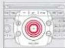
4
Select the filter of your choice
MESSAGES ON ROUTE
ALL WARNING MESSAGE:
ONLY WARNINGS ON ROUT
ALL MESSAGES
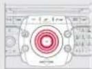
5
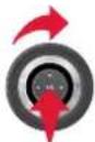
Select "Geo. Filter
GEO. FILTEI
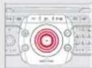
i
When all of the messages on the route are selected, the addit of a geographic fi liter is recommended (within a radius of 3 mil (5 km) for example) to reduce the number of messages displayed on the map. The geographic fi liter follows the movement of tl vehicle.
i
The filters are independent and their results are conceal. We recommend
- a filter over 6 miles (10 km) around the vehicle in heavy tr - a filter over 30 miles (50 km) around the vehicle or a filter or route on motorway journeys.
05 TRAFFIC INFORMATION
PRINCIPAL TMC SYMBOLS
1
Black and blue triangle: general information, for example

Weather reports

Traffic reports

Wind

Fog

Parking

Snow/ice
2
Red and yellow triangle: traffic information, par exam

Modified signage

Narrow carriageway

Slippery surface

Accident

Delay

Roadworks

Risk of explosion

Road closed

Demonstration

Danger

No entry

Traffic jam
RECEIVING TA MESSAGES
i
The TA (Traffi c Announcement) function gives priority to TA messages. To operate, this function needs good reception of a rad station transmitting this type of message. When a traffic report transmitted, the current audio source (Radio, CD, Jukebox, ...) interrupted automatically to play the TA message. Normal playback of the audio source resumes at the end of the transmission of the message.
1

With the current audio source displa on the screen, press the dia
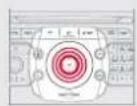
2
The shortcut menu for the source appears and gives access to:
TA
3
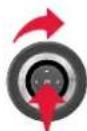
Select Traffic Announcements (1 and press the dial to confirm and g to the associated settings
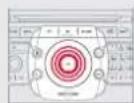
06 RADIC
SELECTING A STATION
The external environment (hill, building, tunnel, underground car park...) may interfere with the reception, including in KUS following mode. This phenomenon is a normal result of the way in which radio waves are transmitted and does not in any way indicate a failure of the audio equipment.

Press the RADIO button to display the list of stations received locally sorted in alphabetical order Select the station required by turning the ring and press to confirm
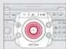

While listening to the radio, press butto ◀ and ▶ for the automatic search for a lower or high frequency.
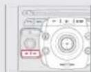

When the "RADIO" screen is displayed, turn t ring or use the 4-direction navigator to select th previous or next station on the lisi

Press one of the buttons on the numeric keypad for more th 2 seconds to store the current station. A bleep confi rms that it h been stored Press the button on the numeric keypad to recall the stored rac station.
RDS - REGIONAL MOD


When the current radio station displayed on the screen, press OK

The radio source short-cuts menu appears and proves access to the following short-cuts
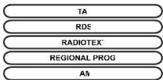
flowchart
graph TD
    A["TA"] --> B["RDS"]
    B --> C["RADIOTEX"]
    C --> D["REGIONAL PROG"]
    D --> E["AI"]

Select the function required and pre: OK to confirm to gain access to the corresponding settings

The RDS, if displayed, allows you to continue listening to the sa station by automatic retuning to alternative frequencies. However, certain conditions, coverage of an RDS station may not be assured throughout the country as radio stations do not cover 100% of the territory. This explains the loss of reception of the station during journey.
The MP3 format, an abbreviation of MPEG 1, 2 & 2.5 Audio Layer and the WMA format, an abbreviation of Windows Media Audio and the property of Microsoft, are audio compression standards which permit the recording of several tens of music files on a single disc.

Connecting an IPO
To play MP3 type files, connect the IPod using the USB port (limi functions). To play iTunes files, connect the IPod using the auxiliary socket (AUX).

In order to be able to play a recorded CDR or CDRW, wh recording it is preferable to select the ISO 9660 level 1, 2 or Jolli standard. If the disc is recorded in another format it may not be played correctly
It is recommended that the same recording standard is always used for an individual disc, with as low a speed as possible (4x maximum for optimum sound quality In the particular case of a multi-session CD, the Joliet standard recommended

In order to be read, a USB memory stick must be formatted to FAT 32.

The audio equipment will only play audio fi les with the extens ".mp3" with a speed of between 8 Kbps and 320 Kbps and th extension ".wma" with a speed of between 5 Kbps and 384 Kbp. It also supports the VBR (Variable Bit Rate) mod No other type of fi le (.mp4,.m3u...) can be playe

It is advisable to restrict fi le names to 20 characters, without using special characters (e.g.: " " ? ; ù) to avoid any playing and displayir problems.

During play, exit the "SD-Card" or "USB" source before removing SD card or the USB memory stick from its reade

To avoid any risk of theft, remove the SD card or the USB mem stick when you leave your vehicle with the roof open.
MP3 CDs. SD cards or USB peripherals are the compatible sources.

Insert the audio or MP3 CD in the playe the SD card in the card reader or the USB peripheral in the USB reader. Play begin automatically

The list of tracks or MP3/WMA fi les appears under "Media" Mei

Press this button

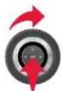
When the "MEDIA" screen i displayed, turn the ring up or down to select the previous or next compatible source.
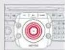


Press the MEDIA buffer

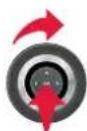
Press the MEDIA button again (select the "Media" Menu function and press OK to confirm
"MEDIA" MENU

Select the "Select media" functio and press OK to confi rr
SELECT MEDIA

Select the music source required Press OK to confirm. Play begins

The playing and displaying of an MP3/WMA compilation may depend on the recording programme and/or the parameters used. We recommend the ISO 9660 recording standard.
When copying is in progress, switching off the ignition will interrupt the process but it will resume directly when the ignition is switched on again.
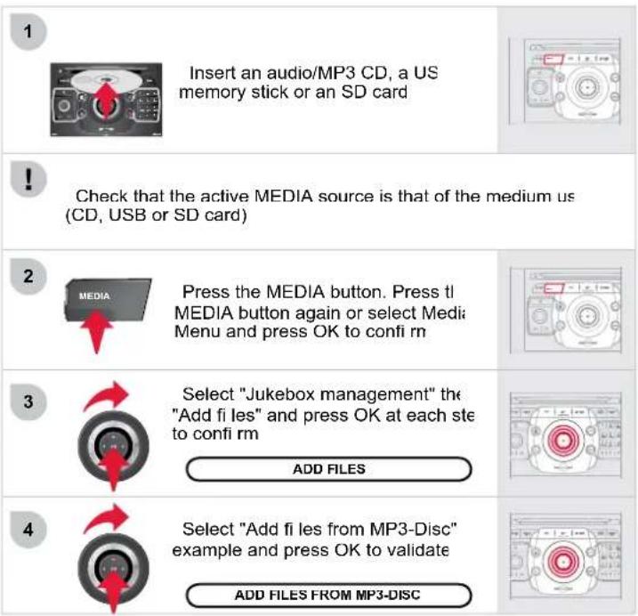
![5 Select the tracks required then "R selection" or select all of the track: using "Rip all" 6 Select "[New folder]" to create a new folder or select an existing folder (created previously) [NEW FOLDER] 7 "Do you want to change the names the tracks that will be ripped?": select "Yes" to change them or "No" YES NO 8 To copy an MP3 CD, then select "Real time ripping", "Fast ripping" "High quality (192 kbit/sec)" o "Standard quality (128 kbit/sec)" then select "Start ripping" 9 Confir rm the warning message pressing "OK" to start the copy OK](/content/2026/05/791482/images/cdadb0e7c7ceaa4083a6bce3eb69d2fc493f3714771cdf841ca2714ee9da767d.jpg)
RENAMING OR DELETING AN ALBUI

Check that the active source is not the Jukebox in order to be able to rename or delete a track/folde

Activate the playing of a source other than the Jukebox (CD, rac etc...)


Press the MEDIA butto

Press the MEDIA button again select Media Menu and press OK to confirm

Select "Jukebox management" ar press OK to confi rn

Select "Modify content" and press C confi rr
MODIFY CONTENT
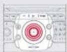
JUKEBOX
Press the MEDIA butto
Press the MEDIA button again of select Media Menu and press OK to confirm
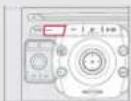

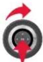
Select "Jukebox management" ar press OK to confirm
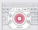

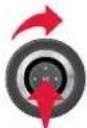
Select "Play options" and press C to confirm
Select "Folders & Files" or "Playlists then press OK to confirm
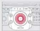

Press the ESC button to return to the first file le Playlists can be created in the Jukebo;
Media Menu> Jukebox management> Create new playlist. Add the tracks required one by one then save the change. The "Playlists" play mode must then be selected
Insert the DVD in the player. Play begin automatically


If the DVD does not appear on the screen, press the MODE button to gain access to the "MEDIA" screen which displays the DVD screen


Press the MEDIA button to ge access to the DVD menu at any time or to the functions of the Media Menu which adjust the video (brightness contrast, image format...)

The 4-direction navigator and the chromed ring allow you to mo the DVD selection cursor. Change chapter by pressing th ▶ or ◀ button.

Select the video source required ("DVD-Video", "External dev (AV)"). Press OK to confirm. Play begins.
USING AN EXTERNAL DEVICE (AUX) AUDIO/VIDEO/RCA CABLE NOT SUPPLIED

Connect the portable equipment (MP3 player, camcorder, camera...) to the RCA socket (white and red for audio; red and yellow for video) in the glove box using a JACK/RCA audio cable

Press the MEDIA button then press it again or select the "Media" Men function and press OK to confirm

If the external device is not activated, select "Ext. Device (Au management" to activate it

Select "Select media" then "Exte device (AV)" and press OK to activat
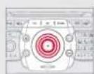

Select the AUX music source an press OK to confirm. Play begin automatically
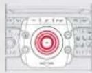

The display and management of the controls is via the portab equipment.
08 USING THE TELEPHONE
CHOOSING BETWEEN THE BLUETOOTH TELEPHONE/INTERNAL TELEPHONE
1

To activate the Bluetooth telepho or the internal telephone, press PICK UP TEL.
2
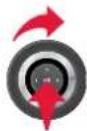
Select Phone menu, then "Sele phone" then choose between "Telephone off", "Use Bluetooth phone" or "Use internal phone" Press OK at each step to confirm
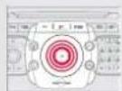
!
The system can only be connected to one Bluetooth telephone a one SIM card (Internal telephone) at the same time In this case, the phone book is synchronised with the Bluetooth telephone.
08 USING THE TELEPHONE
CONNECTING A BLUETOOTI TELEPHONE
* The services available via the telephone depend on the network, the SIM card and the compatibility of the Bluetooth equipment used. Refer to your telephone's manual and your operator to check which services you have access to. A list of mobile telephones which offer the best range of services is available from dealers

For safety reasons and because they require prolonged attention the part of the driver, the operations for pairing the Bluetooth mobi telephone to the hands-free system of the NaviDrive 3D must b carried out with the vehicle stationary and the ignition o

Activate the telephone's Bluetooth functic The last telephone connected is reconnecte automatically


Press the TEL butto

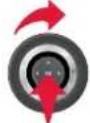
If no telephone is connected, tl system prompts you to "Connec phone". Select "Yes" and press OK t confi rm

The list of telephones connected previously (4 maximum) appears the multifunction screen. Select the telephone required then select "Connect phone" for a new connection. Select "Delete pairing" to cancel the connection to the telephone
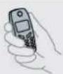

For a first connection, sele "Search phone" and press OK to confirm. Then select the name of the telephone.
SEARCH PHONI

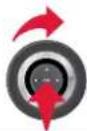
Enter the authentication code on the telephone. The code to be entered i displayed on the screen
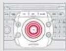

Once the telephone has been connected, the NaviDrive 3D c synchronise the address book and the call list. This synchronistic may take a few minutes


To change the telephone connecte press the TEL button, then selec Phone menu, then "Select phone then "Connect Bluetooth phone then select the telephone required o "Search phone" Press OK at each step to confirm.
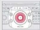
08 USING THE TELEPHONE
USING THE INTERNAL TELEPHONE WITH SIM CARD
If you have declined to use the internal telephone for personal calls, you can still connect a Bluetooth telephone to receive your calls on the vehicle's audio system.
1
Extract the holder by pressing the eject button.
2
Install the SIM card in the holder and then insert it in the slot.
3
To remove the SIM card, repeat step 1.
!
For safety reasons and because they require prolonged attention on the part of the driver, the SIM card installation operations must be carried out when stationary.
1
Enter the PIN code on the keypad then select OK and confirm.
REMEMBER PIN
When entering your PIN code, tick the "Remember PIN" tab to allow use of the telephone without having to enter this code when it is used subsequently.
2
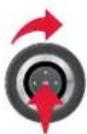
The system asks "Do you want to switch to the internal phone?", select "Yes" if you wish to use your SIM card for your personal calls. Otherwise, only the emergency call and the services will use the SIM card.
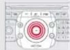
Once the SIM card has been installed, the system can synchronise the address book and the call list. This synchronisation may take a few minutes.
08 USING THE TELEPHONE
RECEIVING A CAL

An incoming call is announced by a ring and a supenposed display on the screen

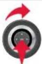
Select the "Yes" tab to accept or "No" to refuse and confirm by pressing OK
YES
NO
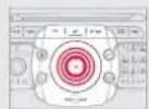

The PICK UP TEL button accepts, the HANG UP TEL button refuses the incoming call

To hang up, press the HANG UP TE button or press OK and select "En call" then confirm by pressing Of
END CAL
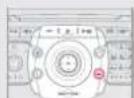

Press the end of the steering mounted control accept the call or end the call in progress
MAKING A CAL

Press the PICK UP TEL buttor
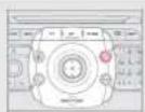

The list of the last 20 calls made and received in the vehicle appeal under "Phone" menu. You can select a number and press OK make the call

Select the "Phone" menu function an press OK to confirm
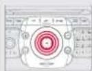

Select "Dial number", then dial th telephone number using the virtua keypad.
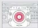
DIAL NUMBER

It is also possible to select a number from the address book. Y can select "Dial from address book". The NaviDrive 3D permits the recording of up to 4 096 entries

Press the end of the steering mounted control for more than tv seconds to open the address book
09 CONFIGURATION
SETTING THE DATE AND TIME

This setting operation must be carried out if the battery has be disconnected

Press the SETUP butto
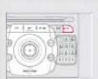

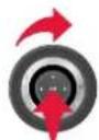
Select the "Date & Time" function at press OK to confirm
DATE & TIMI


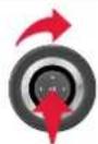
Select the "Set date & time" function and press OK to confirm
SET DATE & TIME
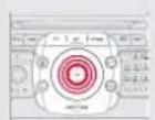

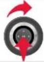
Set the parameters using the rir and move on to the next using the 4-direction navigator Press OK to confi rr
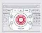
This function provides access to the options in the SETUP men
Principle of the GPS synchro (GMT
1 Confirm the "Synchronise with GPS" selection, the time is then set to GMT universal time, the date is also updated
2. Using the 4-direction navigator, move the cursor to the time fi elds and press OK
3. You can then use the ring to set the time to the time zone of your choice.
Take care when changing between summer/winter time, the time zone must be changed again manually.

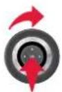
Select the "Date format" function at press OK to confirm Select the format required using th ring and press OK to confirm
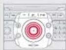

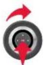
Select the "Time format" function at press OK to confirm Select the format required using the ring and press OK to confirm
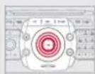

Pressing the SETUP button for more than 2 seconds permits acce
DESCRIPTION OF THE UNI
GPS COVERAGI
DEMO MODI
10 SCREEN MENU MAF

1 MAIN FUNCTION
2 CHOICE,
3 choice A'
3 choice A
2 CHOICE B.

"TRAFFIC" MEN
SELECT PREFERRED LIS
Messages on rout
Only warnings on rout
All warning message:
All message
Geo. Filte
Deactivate Plt
Within 2 miles (3 kn
Within 3 miles (5 km
Within 6 miles (10 km
Within 30 miles (50 km
READ OUT SETTING
On confi rmatic
Incoming message
TMC STATION INFORMATION

"MEDIA" MEN
SELECT MEDI
Audio CD/MP3-Disc/ DVD-Audio /DVD-Vid
Jukebox (Folders & Files
SD-Cari
USE
External device (audio/A)
JUKEBOX MANAGEMEN
Add fi le
Create folde
Modify conten
Edit playlis
Play option:
Folders & Files
Playlists
Memory capacity
SOUND SETTING
Refer to the "Sound settings" menu details of w are shown on the next page
VIDEO SETTING
Aspect ratio
Menu language
Display!
Brightness:
Contras
Colour
AUX standard
Reset video setting
EXT. DEVICE (AUX) MANAGEMENT
Off/Audio/Audio and Video (AV)
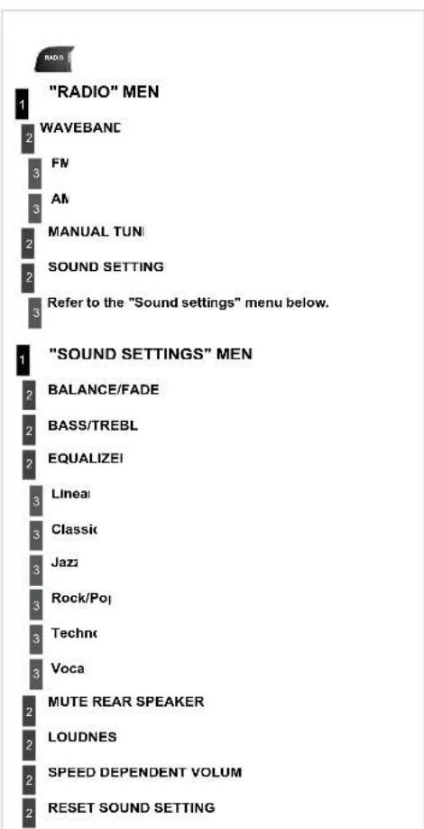
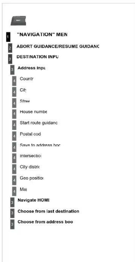
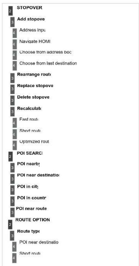
tree
| Node | Category | |---|---| | 1 | STOPOVER | | 2 | Add stopove | | 3 | Address Inpu | | 4 | Navigate HOMI | | 5 | Choose from address boc | | 6 | Choose from last destination | | 7 | Rearrange routi | | 8 | Replace stopove | | 9 | Delete stopove | | 10 | Recalculate | | 11 | Fast routi | | 12 | Short routi | | 13 | Optimized rout | | 14 | POI SEARCI | | 15 | POI nearby | | 16 | POI near destination | | 17 | POI in city | | 18 | POI in countr | | 19 | POI near route | | 20 | ROUTE OPTION | | 21 | Route type | | 22 | POI near destination | | 23 | Short routi |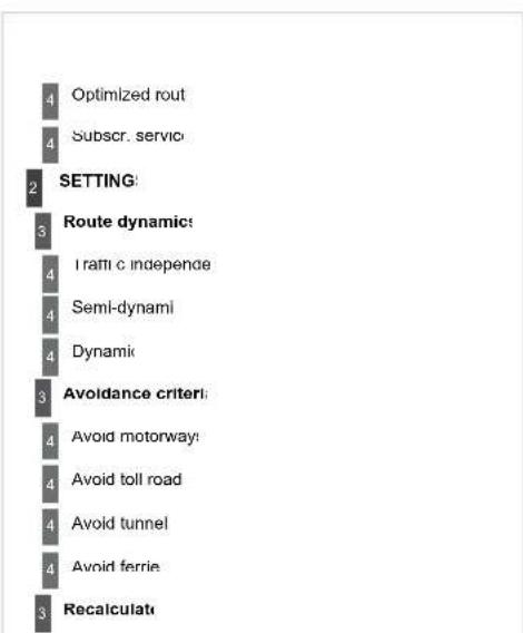
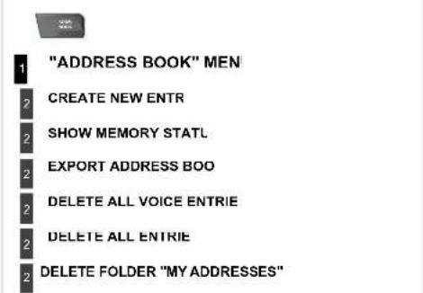
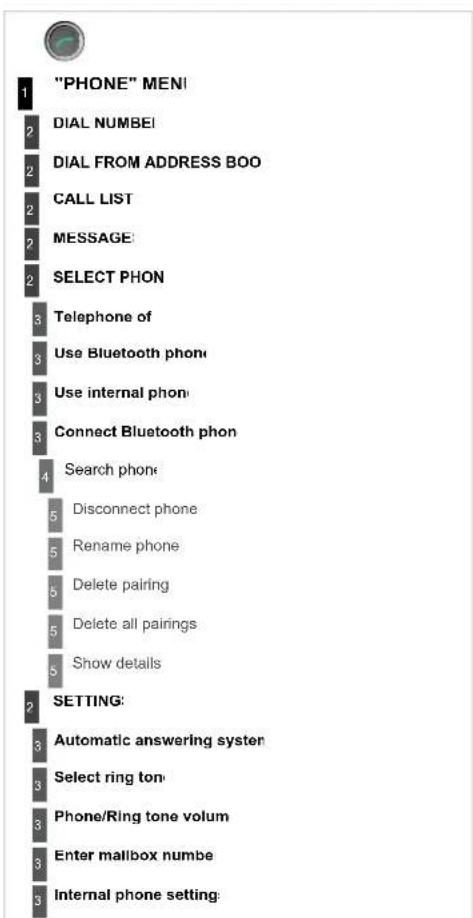
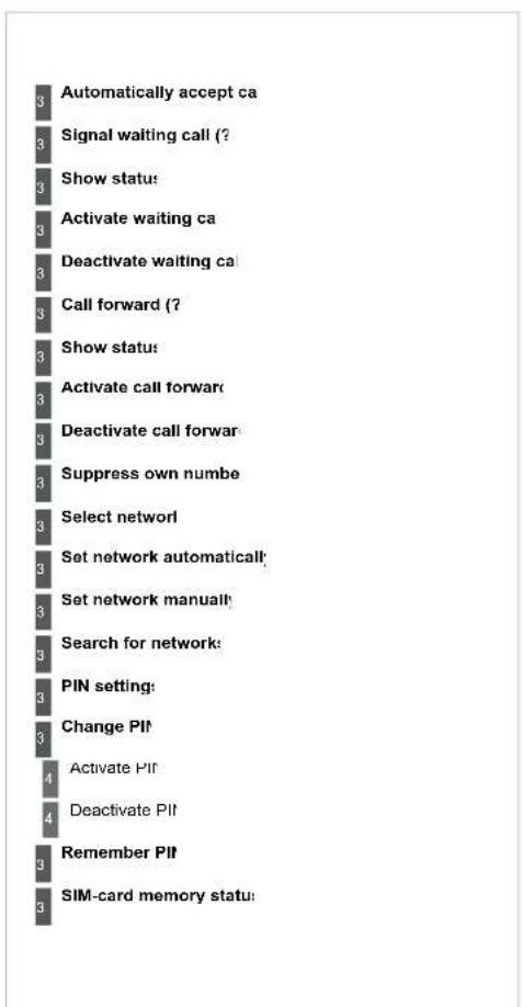
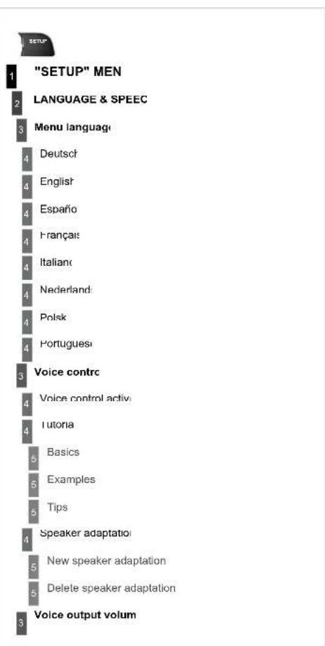
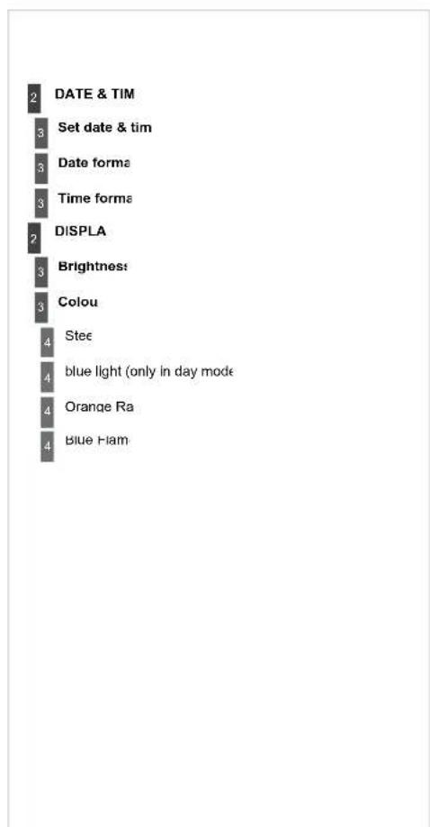
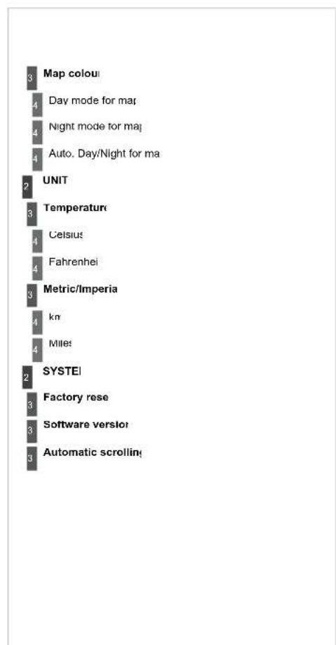
bar
| Feature | Value | |---|---| | Map coloui | 3 | | Day mode for mar | 4 | | Night mode for maj | 4 | | Auto. Day/Night for ma | 4 | | UNIT | 2 | | Temperature | 3 | | Celsius | 4 | | Fahrenheit | 4 | | Metric/Imperia | 3 | | kn | 4 | | Milet | 4 | | SYSTEI | 2 | | Factory rese | 3 | | Software versior | 3 | | Automatic scrolling | 3 |FREQUENTLY ASKED QUESTIONS
| The table below groups together the answers to the most frequently asked questions concerning the NaviDrive 3D. | ||
| QUESTION | ANSWEF | SOLUTION |
| There is a difference sound quality between the different audio sources (radio, CD...) | For optimum sound quality, the audio settings (Volume, Bass, Treb Ambience, Loudness) can be adapted to the different sound source which may result in audible differences when changing source (radio CD...). | Check that the audio settings (Volume, Bas Treble, Ambience, Loudness) are adapted t the sources listened to. It is advisable to se the AUDIO functions (Bass, Treble, Front-Rea Balance, Left-Right Balance) to the middl position, select the musical ambience "Linear and set the loudness correction to the "Active position in CD mode or to the "Inactive" positio in radio mode |
| The CD is ejecte automatically or is no played by the player | The CD is inserted upside down, is unplayable, does not contain any auc data or contains an audio format which the player cannot plaThe CD is protected by an anti-pirating protection system which is r recognised by the audio equipment | - Check that the CD is inserted in the player right way up.- Check the condition of the CD: the CD canr be played if it is too damaged- Check the content in the case of a record CD: consult the advice in the "Audio" sector- The audio equipment's CD player does r play DVDs.- Due to inadequate quality, certain record CDs will not be played by the audio system. |
| The CD player sour is poor | The CD used is scratched or of poor qualit | Insert good quality CDs and store them i suitable conditions. |
| The audio equipment settings (bass, treble, ambiences) are unsuitab | Set the treble or bass level to 0, without selectir an ambience. | |
| QUESTION | ANSWEF | SOLUTION |
| The stored stations c not function (no sound 87.5 Mhz is displayed... | An incorrect waveband is selectc | Press RADIO, select Radio Menu the "Waveband" to return to the waveband on whic the stations are stored |
| The quality of receptic of the radio station listened to gradually deteriorates or the stored stations dc not function (nc sound, 87.5 Mhz is displayed...) | The vehicle is too far from the transmitter used by the station listened to c is no transmitter in the geographical area through which the vehicle is tra | Activate the "RDS" function by means of tr short-cut menu to enable the system to chec whether there is a more powerful transmitter i the geographical area |
| The environment (hills, buildings, tunnels, basement car parks...) blo reception, including in RDS mode | This phenomenon is normal and does not indica a failure of the audio equipment | |
| The aerial is absent or has been damaged (for example when going throua car wash or into an underground car park; | Have the aerial checked by a CITROEN deale | |
| Sound cut-outs (1 to 2 seconds in radic mode. | During this brief sound cut-out, the RDS searches for any frequen permitting better reception of the statior | Deactivate the "RDS" function by means of tr short-cut menu if the phenomenon is too frequer and always on the same route |
| With the engine off, tr system switches off after a few minutes of use | When the engine is switched off, the system's operating time depends (the battery chargeThe switch-off is normal: the system switches to economy mode ar switches off to prevent discharging of the vehicle's batter; | Start the vehicle's engine to increase the batte charge |
| QUESTIOI | ANSWEF | SOLUTION |
| The "TA" box is tickeHowever, certain traffijams along the routeare not indicated in reatime. | On starting, it is several minutes before the system begins to receive tltraffi c informationIn certain countries, only major routes (motorways...) are listed for tltraffi c information | Wait until the traffi c information is being receivcorrectly (displaying of the traffi c informaticsymbols on the map)This phenomenon is normal. The systemdependent on the traffi c information availabl |
| The time taken 1calculate a routesometimes seemslonger than usual | The performance of the system may slow down temporarily if a CD/Dvis being copied onto the Jukebox at the same time as a route is beircalculated. | Wait until the CD/DVD has been copied or stcthe copying before starting the guidance function |
| I receive a speecamera alert for a speecamera which is not ormy route. | The system announces all speed cameras positioned in a cone locatin front of the vehicle. It may detect speed cameras located on nearby parallel roads | Zoom in on the map to view the exact position the speed camera. |
| The speed cameraudible warning doesnot work | The audible warning is not active | Activate the audible warning on Navigation MenSettings, Set parameters for risk areas |
| The alert volume is set to minimun | Increase the volume of the alert when passingspeed camera. | |
| Does the emergency cfunction work without aSIM card? | No, as certain national regulations impose the presence of a SIM cardorder to make an emergency call | Insert a valid SIM card in the slo |
| The altitude is ndisplayed. | On starting, the initialisation of the GPS may take up to 3 minutesreceive more than 4 satellites correctly | Wait until the system has started up completelCheck that there is a GPS coverage of at leas4 satellites (long press on the SETUP buttorthen select "GPS coverage") |
| Depending on the geographical environment (tunnel...) or the weather, tlconditions of reception of the GPS signal may var) | This phenomenon is normal. The systemdependent on the conditions of reception of thGPS signal. | |
| QUESTIO | ANSWEF | SOLUTION |
| The route calculation not successful | The exclusion criteria may conflict with the current location (exclusion toll roads on a toll motorway) | Check the exclusion criteria on the Navigatic Menu ("Route options" - "Avoidance criteria"). |
| There is a long waitir period following the insertion of a CD | When a new medium is inserted, the system reads a certain amount data (directory, title, artist, etc.). This may take a few second | This phenomenon is norma |
| I cannot connect n Bluetooth telephone | The telephone's Bluetooth function may be switched off or the equipme may not be visible | - Check that your telephone's Bluetooth funct is switched on- Check that your telephone is visib |
| The Bluetooth telephone is not compatible with the syster | A list of compatible Bluetooth mobile telephone is available from the dealer network | |
| The volume of t telephone connected | Bluetooth mode is inaudib | The volume depends both on the system and on the telephon | Increase the volume of the MyWay, to maximu if required, and increase the volume of the telephone if necessary |
| The system does n play the DVD | The region protection may not be compatible | Insert DVDs which have compatible regio protection |
| I cannot copy the CD the Jukebox. | The wrong source is selectec | Change the active source to CE |
| The CD is copy-protectec | It is normal that a protected CD cannot be copied. | |
| QUESTIOI | ANSWEF | SOLUTION |
| The system does n receive SMS | The Bluetooth mode does not permit sending of the SMS to the systelThe SIM card used is a twin car | Use your SIM card and the internal telephoneUse the original SIM card to receive the SMS |
| I cannot update th hazardous location POIs. | The Navigation Menu - "Update personal POI" is not displaye | Check that the medium used for the updat (SD card or USB stick) is inserted correctly |
| An error message is displayed at the end of the procedur | - Start the procedure again in fi- Consult a CITROEN dealer if the proble persists.- Check that the data on the MEDIUM supplied by an official partner of CITROEN. | |
| The voice frequencie (DTMF) are no active when I am communicating and press numbers on the keypad. | The numeric buttons on the keypad are only active for calls if the display in telephone mode | To activate them, press the MODE button un the telephone is displayed on the screen |
| An accident area whic does not concern me is displayed on the screen | The accident areas are displayed near a point defi ned on the map and relation to a direction of travel | The alert may be triggered when travelling under a road or near a road which has a speed camera. |
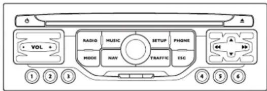

The MyWay is protected in such a way that it will operate in your vehicle. If it is to be installed in another vehicle, contact a CITROËN dealer for configuration the system.

For safety reasons, it is imperative that the driver carry out operations which require prolonged attention while the vehicle is stationary
When the engine is switched off and to preve discharging of the battery, the MyWay switches c following the activation of the Energy Economy mode.

Certain functions described in this handbook will becor available during the course of the year.
MyWay
MULTIMEDIA AUDIO EQUIPMENT/BLUETOOTH TELEPHONE
GPS EUROPE BY SD CARD
CONTENT:
• 01 First steps p 250
• 02 Steering mounted controls p
• 03 General operation p 252
• 04 Navigation - Guidance p 254
• 05 Traffic information p 261
• 06 Radio p 263
• 07 Music media players p 264
• 08 Bluetooth telephone p 267
• 09 Configuration p:
• 10 Screen menu map p 2
- Frequently asked questions p 273
01 FIRST STEPS MyWay CONTROL PANE
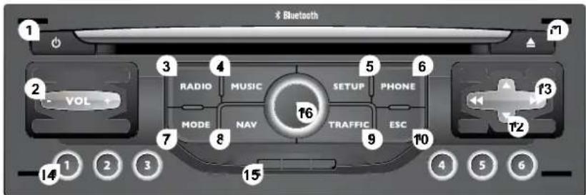
-
Engine not running
-
Short press: on/off.
- Long press: CD pause, mute for the radio.
Engine running - Short press: CD pause, mute for the radio.
- Long press: reinitialisation of the system.
2 Volume adjustment (each source is independent, including navigation messages and alerts
3. Access to the "Radio" Menu. Display the list of stations.
4. Access to the "Music" Menu. Display the tracks.
3 - 4 Long press: access to the audio settings: front/rear and left/right balance, bass/treble, equalizer, loudness, automat volume adjustment, initialise the settings:
5. Access to the "SETUP" Menu.
Long press: access to the GPS coverage and the demonstration mode
6 Access to the "Phone" Menu. Display the call list.
7 Access to the "MODE" Menu.
Selection of the successive display of:
Radio, Map, NAV (if navigation is in progress),
Telephone (if a conversation is in progress). Trip Compute
Long press: display of a black screen (DARK).
8 Access to the "Navigation" Menu. Display the last destinations.
9. Access to the "Traffic" Menu. Display the current traffic alerts
10 ESC: abandon the operation in progress
11. CD eject.
12 Selection of the previous/next radio station from the list.
Selection of the previous/next CD.
Selection of the previous/next MP3 directory.
Selection of the previous/next page of a list.
13 Selection of the previous/next radio station
Selection of the previous/next CD or MP3 track.
Selection of the previous/next line of a list.
14 Buttons 1 to 6
Selection of the stored radio station.
Selection of the CD in the CD changer.
Long press: store the current radio station.
15 Reader for navigation SD card only
16 Dial for selection of the screen display and according to the context of the menu
Short press: contextual menu or confirmation.
Long press: specific contextual menu of the list displayed.
02 STEERING MOUNTED CONTROLS
C5 STEERING MOUNTED CONTROL

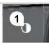
- Successive presses: "Black Panel" mode - black screen (night driving)
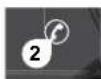
- Short press to make a telephone call. Pick up/Hang up. Access the telephone menu. Display the call list. Long press to reject an incoming call.
Press: repeat the current navigati instruction.
Successive presses: selection of the ty of information present on the screen.

- Rotation: provides access to the short-cut menus according to the display on the screen. Short press: confirm the choice displayed on the screen. Long press: return to the main menu.
4 Short press: abandon the current operation. Reject an incoming call. Long press: return to the initial display.
-
Menu: provides access to the main menu.
-
VOL +: volume increase.
7 VOL -: volume decrease.
-
Successive presses: mute/restore sound.
-
Short press: Radio: higher frequency. Music players: next track. Long press for fast play.
-
Short press: Radio: lower frequency Music players: previous track. Long press for fast play.
-
Short press: display the list of radio frequencies available or the list of tracks albums, directories Long press: update the list of stations received.
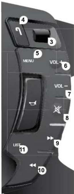
Press the MODE button several times in succession for access to the following menu
RADIO/MUSIC MEDIA PLAYER
flowchart
graph TD
    A["MODE"] --> B
    B --> C
    C --> A
FULL SCREEN MA
TELEPHON (If a conversation is in progress
NAVIGATIO (If guidance is in progress
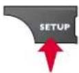
SETUI
system language *, date and time *, di: vehicle settings *, unit and system settings, "Demo m
* Depending on moc
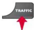
TRAFFI
TMC information and messages

For cleaning the screen, the use of a soft, non-abrasive cloth (spectacles cloth) is recommended, with no additional product.

For a detailed global view of the menus availab refer to the "Screen menu map" section.
DISPLAY ACCORDING TO THE CONTEXT

A press on the OK dial gives access 1 short-cut menus according to the display on the screen.
NAVIGATION (IF GUIDANCE IS IN PROGRES)

ABORT GUIDANCI
REPEAT ADVICI
BLOCK ROAL
ROUTE INFO
SHOW DESTINATION!
TRIP INFC
Route typ
Avoit
Satellite
ZOOM/SCROLI
VOICE ADVICI
ROUTE OPTIONS
TELEPHONE

END CALI
HOLD CALI
DIAI
DTMF-TONE:
PRIVATE MODI
MICRO OFF
MUSIC MEDIA PLAYER:

TRAFFIC INFO (TA
PLAY OPTION:
NORMAL ORDEF
RANDOM TRACI
REPEAT FOLDEF
SCAN
SELECT MUSIC
RADIC

IN FM MOD

TRAFFIC INFO (TA
RDS
RADIOTEX
REGIONAL PROG
AN
IN AM MOD
TA
REFRESH AM LIS
FN
FULL SCREEN MAI

ABORT GUIDANCE /RESUME GUIDANC
SET DESTINATION
POIS NEARBY
POSITION INFO
MAP SETTINGS
ZOOM/SCROLI
04 NAVIGATION - GUIDANCI
SELECTING A DESTINATION
Insert the SD card in the front panel reader and leave it there to use the Navigation functions.
The navigation SD card data must not be modified
Map data updates are available from CITROEN dealer
1
Press the NAV butto
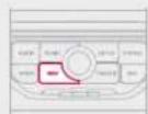

The list of the last 20 destinations appears under the Navigati Menu function
2

Press the NAV button again or select the Navigation Menu function and press the dial to confirm
NAVIGATION MEN!
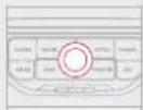
3

Select the "Destination input" function and press the dial to confirm
DESTINATION INPU
4

Select the "Address input" function and press the dial to confirm
ADDRESS INPUT
5

Once the country has been selecte turn the dial and select the tow function. Press the dial to confi rn
6

Select the letters of the town one one confi rming each time by pressin the dial.

A pre-set list (by entering the first few letters) of the towns in country selected can be accessed via the LIST button on the virtu keypad.
04 NAVIGATION - GUIDANCI
7

Turn the dial and select O Press the dial to confi rr

To speed up the process, the post code can be entered directly at selecting the "Postal code" function Use the virtual keypad to enter the letters and digit
8

Repeat steps 5 to 7 for the "Stree and "House number" functions

Select the "Save to address book" function to record the address entered in a directory file. Press the dial to confirm the selection MyWay allows up to 4 000 contact files to be recorded
9
During guidance, pressing the er of the lighting stalk repeats the las guidance instruction
To clear a destination; from steps 1 to 3, select "Choose from last destinations". A long press on one of the destinations displays a list of actions from which you can select Delete entry. Delete lis
10

Then select "Start route guidance and the press the dial to confirm
START ROUTE GUIDANCE

Select the route typ
"Fast route", "Short route" or "Optimized route" and press the dial to confirm It is also possible to select a destination via "Choose from address book" or "Choose from last destinations".
CHOOSE FROM ADDRESS BOOK
CHOOSE FROM LAST DESTINATION

You can zoom in/zoom out on the map using the di It is possible to scroll the map or select its orientation via the sho cut menu of the FULL SCREEN MAP. Press the dial then sele "Map settings"
04 NAVIGATION - GUIDANCI
ROUTE OPTION
The route selected by the MyWay audio/telephone depends directly on the route option. Changing these options may change the route complete
1
Press the NAV butto
2

Press the NAV button again or select the Navigation Menu function and press the dial to confirm
NAVIGATION MEN
3

Select the "Route options" function and press the dial to confirm
ROUTE OPTIONS
4

Select the "Route type" function at press the dial to confirm. This function allows you to change the route type
ROUTE TYPE
5

Select the "Route dynamics" functic This function gives access to th "Traffi c independent" or "Sen dynamic" options
ROUTE DYNAMICS
6

Select the "Avoidance criteria function. This function provides access to the AVOID option (motorways, toll roads, ferries)
AVOIDANCE CRITERI/
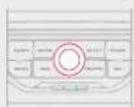
7

Turn the dial and select tr "Recalculate" function to take into account the route options selected Press the dial to confi rr
RECALCULATI
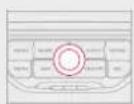
04 NAVIGATION - GUIDANCI
ADDING A STOPOVE
Stopovers can be added to the route once the destination has been select
1
Press the NAV buttor
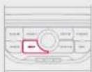
2

Press the NAV button again or select the "Navigation" Menu function and press the dial to confirm
"NAVIGATION" MEN!
3

Select the "Stopovers" function an press the dial to confirm
STOPOVERS
4

Select the "Add stopover" functic (5 stopovers maximum) and press the dial to confirm
ADD STOPOVEF
5

Enter a new address, for example
ADDRESS INPUT
6

Once the new address has bee entered, select OK and press the dia to confi rr
OH
7

Select "Recalculate" and press th dial to confirm
RECALCULATI
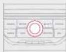

The stopover must be completed or deleted in order for the guidance to continue to the next destination. Otherwise, the MyWay will always return you to the previous stopover
04 NAVIGATION - GUIDANCI
SEARCHING FOR POINTS OF INTERES (POI)
The points of interest (POI) indicate all of the service locations in the vicinity (hotels, various businesses, airports...)
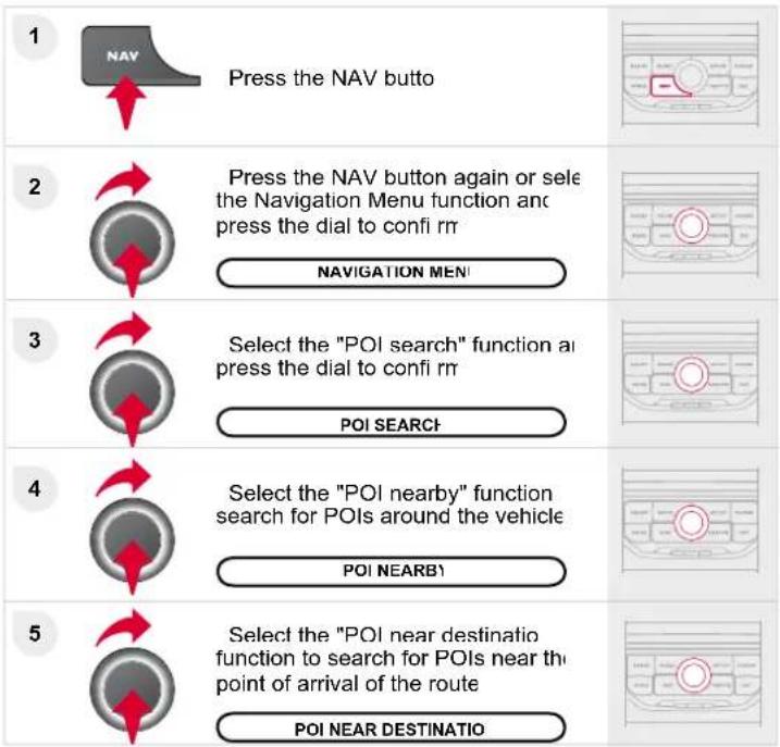
flowchart
graph TD
    A["1"] --> B["Press the NAV butto"]
    B --> C["2"]
    C --> D["Press the NAV button again or select the Navigation Menu function and press the dial to confi rr"]
    D --> E["NAVIGATION MEN"]
    E --> F["3"]
    F --> G["Select the "POI search" function ai press the dial to confi rr"]
    G --> H["POI SEARCH"]
    H --> I["4"]
    I --> J["Select the "POI nearby" function search for POIs around the vehicle"]
    J --> K["POI NEARB"]
    K --> L["5"]
    L --> M["Select the "POI near destination function to search for POIs near the point of arrival of the route"]
    M --> N["POI NEAR DESTINATION"]
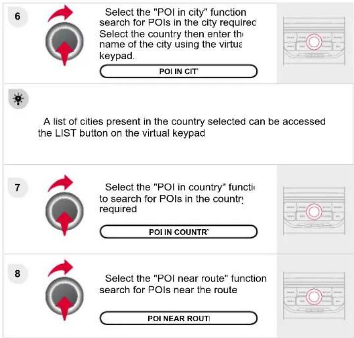
LIST OF PRINCIPAL POINTS OF INTEREST (PO
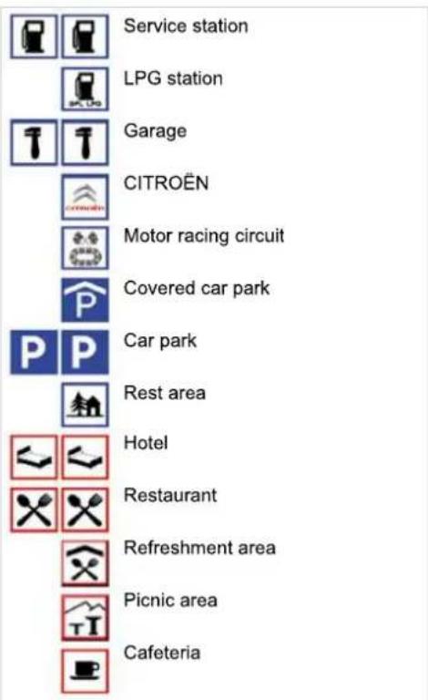
* According to availability in the cour
04 NAVIGATION - GUIDANCI
NAVIGATION SETTING
1
Press the NAV buttc
2

Press the NAV button again or select the Navigation Menu function and press the dial to confirm
NAVIGATION MENU
3

Select the "Settings" function at press the dial to confirm
4

Select the "Navi volume" function at turn the dial to set the volume of each voice synthesiser (traffic information alert messages...)
NAVI VOLUME
[Non-Text]
The volume of the Risk Areas POIs alert can only be adjust during this type of alert
5

Select the "POI categories on Ma function to select the POIs to be displayed on the map by default
POI CATEGORIES ON MA
6

Select "Set parameters for risk area to gain access to the "Display or map", "Visual alert" and "Sound alert functions
SET PARAMETERS FOR RISK AREA
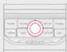
i
UPDATING THE RISK AREAS POI
This requires an SDHC (High Capacity) compatible reader. Download the update file from the Internet (www.citroen.fr www.citroen.co.uk)
Open this file and copy the extracted documents to the DATABASE folder on the SD card, replacing the existing file
05 TRAFFIC INFORMATIC
CONFIGURE THE FILTERING AND DISPLAY OF TMC MESSAGES
1
Press the TRAFFIC butto
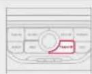

The list of TMC messages appears under the Traffic Menu sorter order of proximity
2

Press the TRAFFIC button again select the Traffic c Menu function ar press the dial to confi rr
TRAFFIC MENI
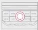
3

Select the filter of your choice
MESSAGES ON ROUTE
ALL WARNING MESSAGE:
ONLY WARNINGS ON ROUT
ALL MESSAGES
The messages appear on the ma and on the list To exit, press ESC
IMC (Traffic Message Channel) messages contain information on traffic and weather conditions, received in real time and transmitted to the driver in the form of audible announcements and symbols on the navigation map The navigation system can then suggest an alternative route to avoid a traffic problem.
4

Select the "Geo. Filter" function ar press the dial to confi rm
GEO. FILTEI
5

Then select the radius of the fi iter miles (km) required in accordance with the route, press the dial to confirm When all of the messages on the route are selected, the addition of a geographical fi iter is recommende (within a radius of 3 miles (5 km) fo example) to reduce the number o messages displayed on the map The geographical fi iter follows th movement of the vehicle.
!
The fil ters are independent and their results are cumulati We recommend a fi iter on the route and a fi iter around the vehicle - 2 miles (3 km) or 3 miles (5 km) for a region with heavy tra - 6 miles (10 km) for a region with normal trafi - 30 miles (50 km) for long journeys (motorway).
05 TRAFFIC INFORMATIC
PRINCIPAL TMC SYMBOLS
RECEIVING TA MESSAGES
1 Black and blue triangle: general information, for example

Weather reports

Traffic reports

Wind

Fog

Parking

Snow/ice
2 Red and yellow triangle: traffic information, par exam

Modified signage

Narrow carriageway

Slippery surface

Accident

Delay

Roadworks

Risk of explosion

Road closed

Demonstration

Danger

No entry

Traffic jam
i
The TA (Traffi c Announcement) function gives priority to TA messages. To operate, this function needs good reception of a rad station transmitting this type of message. When a traffic report transmitted, the current audio source (Radio, CD, Jukebox, ...) interrupted automatically to play the TA message. Normal playback of the audio source resumes at the end of the transmission of the message.
1

With the current audio sourc displayed on the screen, press the dial.
2
The shortcut menu for the source appears and gives access to:
TA
3

Select Traffic Announcements (1 and press the dial to confirm and g to the associated settings
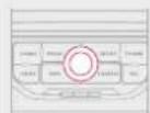
06 RADIC
SELECTING A STATION
1
Press the RADIO button to display the list of stations received locally sorted in alphabetical order Select the station required by turning the dial and press to confirm
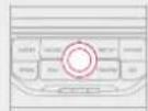

While listening to the radio, press one of tl buttons to select the previous or next station o the list
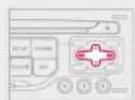

A long press of one of the buttons starts t automatic search for a station with a lower c higher frequency

Press one of the buttons on the numeric keypad for more than 2 seconds to store the current station Press the button on the numeric keypad to recall the stored rack station.
The external environment (hill, building, tunnel, underground car park...) may interfere with the reception, including in RUS following mode. This phenomenon is a normal result of the way in which radio waves are transmitted and does not in any way indicate a failure of the audio equipment
RDS - REGIONAL MODE
1

When the current radio station displayed on the screen, press the dial.
2
The radio source short-cuts menu appears and proes access to the following short-cuts
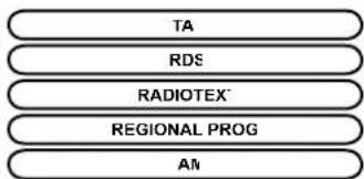
flowchart
graph TD
    A["TA"] --> B["RDS"]
    B --> C["RADIOTEX"]
    C --> D["REGIONAL PROG"]
    D --> E["AI"]
3

Select the function required and pre- the dial to confirm to gain access | the corresponding settings

RDS, if displayed, allows you to continue listening to the sar station by automatic retuning to alternative frequencies. However, certain conditions, coverage of an RDS station may not be assure throughout the entire country as radio stations do not cover 100% of the territory. This explains the loss of reception of the station during a journey
The MP3 format, an abbreviation of MPEG 1, 2 & 2.5 Audio Laye and the WMA format, an abbreviation of Windows Media Audio at the property of Microsoft, are audio compression standards which permit the recording of several tens of music files on a single disc.

In order to be able to play a recorded CDR or CDRW, wh recording it is preferable to select the ISO 9660 level 1, 2 or Jolil standard.
If the disc is recorded in another format it may not be played correctly
It is recommended that the same recording standard is always used for an individual disc, with as low a speed as possible (4x maximum for optimum sound quality
In the particular case of a multi-session CD, the Joliet standard recommended

The MyWay will only play audio fi les with the extension ".mp3" v a speed of between 8 Kbps and 320 Kbps and the extension ".wma with a speed of between 5 Kbps and 384 Kbps It also supports the VBR (Variable Bit Rate) mod No other type of fi le (.mp4, .m3u...) can be playe

It is advisable to restrict fi le names to 20 characters, without us special characters (e.g.: " " ? ; ù) to avoid any play or displa problems.
The list of tracks or MP3/WMA files appears under "Music" Mei
2

Press the MUSIC button again o select the "Music" Menu function and press the dial to confi rm
"MUSIC" MENL
3

Select the "Select music" function an press the dial to confi rr
SELECT MUSIK
4

Select the music source required CD, MP3/WMA CD. Press the dial to confirm. Play begins
5
Press the up or down button to select the next/previous folder
6
Press one of the buttons to select music track Press and hold one of the buttons for fast forward or rewind play
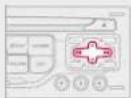

The playing and displaying of an MP3/WMA compilation ma depend on the recording programme and/or the settings used. W recommend the ISO 9660 file standard
Connect the portable device (MP WMA player...) to the JACK socke using a suitable cable
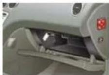
2
Press the MUSIC button then pre- it again or select the Music Meni function and press the dial to confi rm
MUSIC MENL
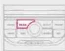
3

Select the External device function and press the dial to activate it
EXTERNAL DEVICI
4

Select the AUX music source at press the dial to confirm. Play begin automatically
!
Display and management of the controls are via the portable device.
CD CHANGER
PLAYING A CD (NOT MP3/WMA COMPATIBLE
1
Insert one or more CDs in tl changer. Press the MUSIC button
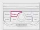
2

Press the MUSIC button again select the Music Menu function and press the dial to confirm
MUSIC MENI
3

Select the "Select music" function at press the dial to confirm
SELECT MUSIC
4

Select the "CD Changer" mus source and press the dial to confi rn
CD CHANGEF
5


Press one of the buttons on the numeric keypad to select the corresponding CD
08 BLUETOOTH TELEPHONE

CONNECTING A TELEPHONE
* The services available depend on the network, the SIM card and the compatibility of the Bluetooth telephone used. Check the telephone manual and with your network provider for details of the services available to you. A list of mobile telephones with the best level of compatibility is available from the dealer network
!
For reasons of safety and because they require prolonged attention on the part of the driver, the operations for pairing the Bluetooth mobile telephone to the hands-free system of the MyWay must be carried out with the vehicle stationary. The ignition must be on.
1
Activate the telephone's Bluetooth functic The last telephone connected is reconnecte automatically
2
Press the PHONE butto
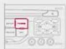
#
The list of telephones connected previously (4 maximum) appears on the multifunction screen. Select the telephone required for a connection.
3

For a first connection, select "Search phone" and press the dial to confirm. Then select the name of the telephone.
SEARCH PHONI
4

Enter the authentication code on the telephone. The code to be entered i displayed on the screen
i
Once the telephone has been connected, MyWay can synchron the address book and the call list. This synchronisation may take few minutes *
1
To change the telephone connecte press the PHONE button, then select Phone Menu and press the dial to confirm
2

Select "Connect phone". Select the telephone and press to confirm
CONNECT PHONE
08 BLUETOOTH TELEPHONE
RECEIVING A CAL
1
An incoming call is announced by a ring and a superimposed display on the multifunction screen
2

Select the "Yes" tab to accept or "No" to refuse and confirm by pressing the dial.
YES
NO
3

To hang up, press the PHONE butto or press the dial and select "End call then confirm by pressing the dia
END CAL

Press the end of the steering mounted control to accept the call or end the call in progress
MAKING A CAL
1

Press the PHONE button

The list of the last 20 calls made and received in the vehicle appeal under "Phone" Menu. You can select a number and press the dial make the call.
2

Select the "Phone" Menu function an press the dial to confirm
"PHONE" MENI
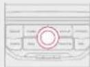

It is also possible to select a number from the address book. You can select "Dial from address book". The MyWay permits the recording up to 4 000 entries
Press the end of the steering wheel control for more than two seconds to gain access to the address book

To delete a number, press the PHONE button then press and hold a call number to display a list of actions including
Delete entr
Delete lis
09 CONFIGURATION
SETTING THE DATE AND TIME
The SETUP function gives access to the following options: System language, Date & Time, Display (Brightness, Colour, Map colour), Vehicle, Units, System
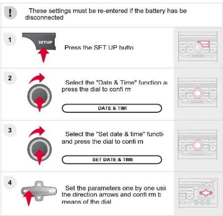
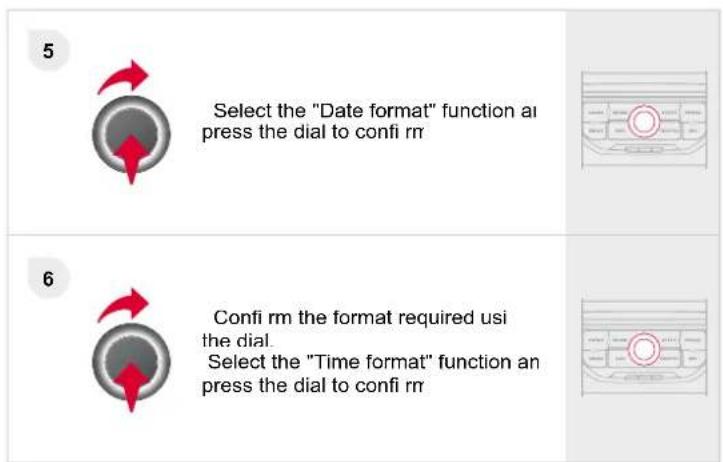

10 SCREEN MENU MAF

1 MAIN FUNCTION
2 CHOICE,
3 choice A
3 choice A
2 CHOICE B.

"TRAFFIC" MEN
MESSAGES ON ROUT
ONLY WARNINGS ON ROUT
ALL WARNING MESSAGE:
ALLMESSAGE:
GEO. FILTEF
Within 2 miles (3 kr
Within 3 miles (5 k
Within 6 miles (10 k)
Within 30 miles (50 k
Within 60 miles (100 km)

"MUSIC" MEN
2 SELECT MUSI
2 SOUND SETTING:
3 Balance/Fade
Bass/Trebl
Equalize
4 Linea
4 Classi
Jazz
Kock/Pop
Techn
4 Voca
3 Loudness
3 Speed dependent volum
3 Reset sound setting

"RADIO" MEN
2 WAVEBAN
3 FN
3 AN
2 MANUAL TUN
SOUND SETTING!
3 Balance/Fade
3 Bass/Trebl
3 Equalize
4 Linea
Classi
Jaz;
4 Rock/Pop
Techn
Voca
Loudnes
3 Speed dependent volun
3 Reset sound setting

1 "NAVIGATION" MEN
2 ABORT GUIDANCE/RESUME GUIDANC
DESTINATION INPU
3 Address input
4 Country
4 City
Stree
House numbe
4 Start route guidano
4 Postal code
4 Save to address boo
4. Intersection
4 City district
Geo position
4 Mar
Navigate HOME
Choose from address boo
Choose from last destination
TMC station informatic
2 STOPOVER
3 Add stopover
4 Address input
4 Navigate HOME
4 Choose from address boo
4 Choose from last destination
3 Rearrange route
3 Replace stopover
3 Delete stopover
3 Recalculate
4 Fast route
Short route
4 Optimized route
2 POI SEARC
3 POI nearby
3 POI near destination
2 POI in city
POI in country
2 POI near route
2 ROUTE OPTION
3 Route typ
4 Fast route
4 Short route
4 Optimized rout
3 Route dynamic
4 Traffi c independe
Semi-dynami
3 Avoidance criteri:
4 Avoid motorway
4 Avoid toll road
Avoid terrie
Recalculate
2 SETTING:
3 Navi volum
POI categories on Ma
3 Set parameters for risk area
4 Display on ma
4 Visual ale
Sound alert
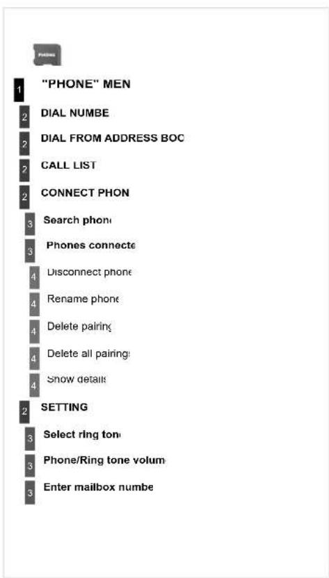
* Available according to mo
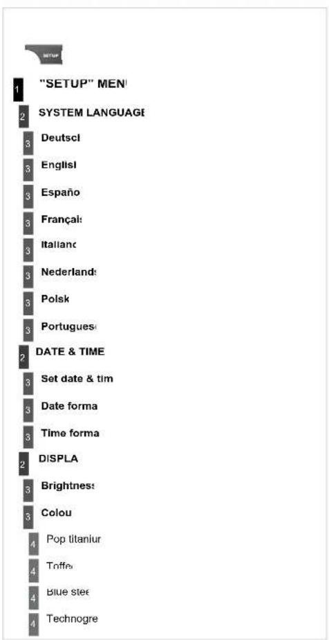
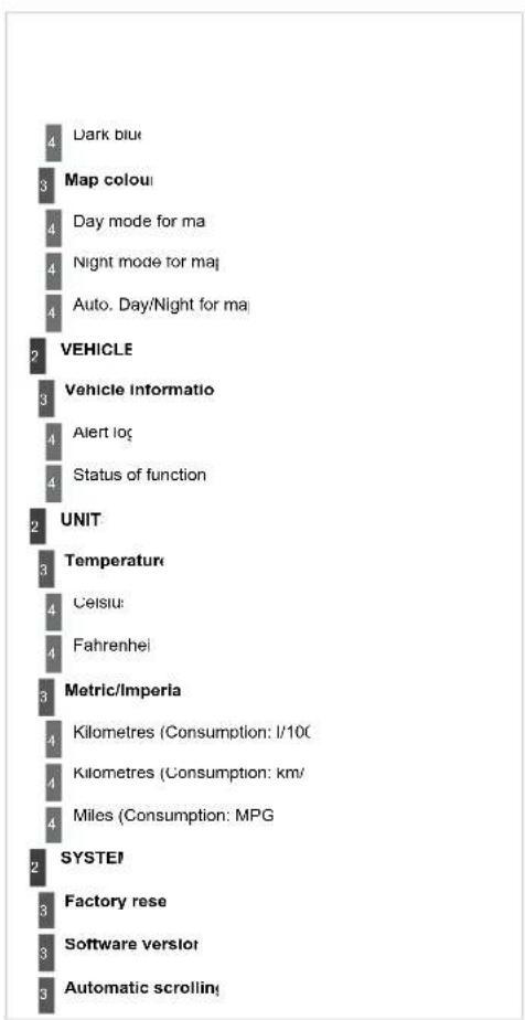
tree
| Level | Item | Value | |---|---|---| | 1 | Dark blue | 4 | | 2 | Map colour | 3 | | 3 | Day mode for ma | 4 | | 4 | Night mode for maj | 4 | | 5 | Auto. Day/Night for ma | 4 | | 6 | VEHICLE | 2 | | 7 | Vehicle Informatio | 3 | | 8 | Alert loc | 4 | | 9 | Status of function | 4 | | 10 | UNIT | 2 | | 11 | Temperature | 3 | | 12 | Celsius | 4 | | 13 | Fahrenheit | 4 | | 14 | Metric/Imperia | 3 | | 15 | Kilometres (Consumption: I/10€) | 4 | | 16 | Kilometres (Consumption: km/ ) | 4 | | 17 | Miles (Consumption: MPG) | 4 | | 18 | SYSTEI | 2 | | 19 | Factory rese | 3 | | 20 | Software versloi | 3 | | 21 | Automatic scrolling | 3 |FREQUENTLY ASKED QUESTIONS
| QUESTIO | ANSWEI | SOLUTION |
| There is a difference sound quality between the different audic sources (radio, CD...) | For optimum sound quality, the audio settings (Volume, Bass, Treb Ambience, Loudness) can be adapted to the different sound source which may result in audible differences when changing source (radio CD...). | Check that the audio settings (Volume, Bas Treble, Ambience, Loudness) are adapted t the sources listened to. It is advisable to se the AUDIO functions (Bass, Treble, Front-Rea Balance, Left-Right Balance) to the middl position, select the Linear musical ambienc and set the loudness correction to the "Active position in CD mode or to the "Inactive" positio in radio mode |
| The CD is ejecte automatically or is no played by the player | The CD is inserted upside down, is unplayable, does not contain any auc data or contains an audio format which the player cannot plaThe CD is protected by an anti-pirating protection system which is r recognised by the audio equipment | - Check that the CD is inserted in the player right way up.- Check the condition of the CD: the CD canr be played if it is too damaged- Check the content in the case of a record CD: consult the advice in the Audio sector- The audio equipment's CD player does r play DVDs.- Because of their quality level, certain writeat CDs will not be played by the audio system. |
| The CD player sour is poor | The CD used is scratched or of poor qualit | Insert good quality CDs and store them i suitable conditions. |
| The audio equipment settings (bass, treble, ambiences) are unsuitab | Set the treble or bass level to 0, without selectir an ambience. | |
| QUESTION | ANSWEF | SOLUTION |
| The stored stations c not function (no sound 87.5 Mhz is displayed...) | An incorrect waveband is selected | Press the BAND AST button to return the waveband (AM, FM1, FM2, FMAST) on which the stations are stored |
| The quality of receipt of the radio station listened to gradually deteriorates or the store stations do not function (no sound, 87.5 Mhz i displayed...) | The vehicle is too far from the transmitter used by the station listened to there is no transmitter in the geographical area through which the vehic is travelling. | Activate the RDS function to enable the syste to check whether there is a more powerf transmitter in the geographical area |
| The environment (hills, buildings, tunnels, basement car parks...) blo reception, including in RDS mode | This phenomenon is normal and does no indicate a failure of the audio equipmen | |
| The aerial is absent or has been damaged (for example when goit through a car wash or into an underground car park. | Have the aerial checked by a CITROËN deale | |
| Sound cut-outs of 1 2 seconds in radio mod | During this brief sound cut-out, the RDS searches for any frequen permitting better reception of the stator | Deactivate the RDS function if the phenomenc is too frequent and always on the same route |
| With the engine of the audio equipment switches off after a few minutes of useQUESTIOI | When the engine is switched off, the audio equipment operating tin depends on the battery chargeThe switch-off is normal: the audio equipment switches to economy mo and switches off to prevent discharging of the vehicle's batterANSWEF | Start the vehicle's engine to increase the batte charge.SOLUTION |
| The TA box is tickeHowever, certain traffijams along the routeare not indicated in reatime. | On starting, it is several minutes before the system begins to receive tltraffi c informationIn certain countries, only major routes (motorways...) are listed for tltraffi c information | Wait until the traffi c information is being receivcorrectly (displaying of the traffi c informaticsymbols on the map)This phenomenon is normal. The systemdependent on the traffi c information availabl |
| The time taken tcalculate a routésometimes seemslonger than usual | The performance of the system may slow down temporarily if a CDbeing copied onto the Jukebox at the same time as a route is beincalculated. | Wait until the CD has been copied or stop trcopying before starting the guidance function |
| I receive a speecamera alert for acamera which is not ormy route | The system announces all speed cameras located in a conical zorforward of the vehicle. It may detect speed cameras on nearby or parallroads | Zoom the map to view the exact position of thspeed camera. |
| The audible speecamera alert is noworking. | Audible alerts are not active | Activate audible alerts in Navigation MenSettings, Set parameters for risk areas |
| The alert volume level is set to minimun | Increase the speed camera alert volumc | |
| The altitude is ndisplayed. | On starting, the initialisation of the GPS may take up to 3 minutesreceive more than 3 satellites correctly | Wait until the system has started up completelCheck that there is a GPS coverage of at leas3 satellites (long press on the SETUP buttorthen select GPS coverage) |
| The route is ncalculated successfully | Depending on the geographical environment (tunnel...) or the weather, tlconditions of reception of the GPS signal may var) | This phenomenon is normal. The systemdependent on the conditions of reception of thGPS signal |
| The exclusion criteria may conflict with the current location (exclusiontoll roads on a motorway with tolls) | Check the exclusion criterie | |
| QUESTIO | ANSWEF | SOLUTION |
| There is a long waitin time after inserting a CD | When a new medium is inserted, the system reads a certain amount data (directory, title, artist, etc.). This may take a few second | This phenomenon is norma |
| I cannot connect n Bluetooth telephone | The telephone's Bluetooth function may be deactivated or the equipme may not be visible | - Check that your telephone's Bluetooth funct is activated- Check that your telephone is visible. |
| A telephone connects by Bluetooth is inaudible. | The volume level depends on both the system and the telephor | Increase the MyWay volume setting, possibly maximum, and increase the telephone volume level if necessary |
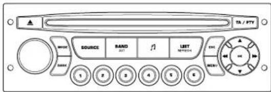
Audio System
AUDIO EQUIPMENT/BLUETOOTH SYSTEM

Your Audio system is coded in such a way that it will only operate in your vehicle. If it is to be installed in another vehicle, contact a CITROËN dealer for configuration the system.

For safety reasons, the driver must only carry c operations which require prolonged attention while the vehicle is stationary
When the engine is switched off and to prevent discharging of the battery, your Audio system may switch off after a few minutes
CONTENT:
• 01 First steps p 278
• 02 Steering mounted controls p
• 03 General menu p 280
• 04 Audio p 281
• 05 USB Box p 284
• 06 Bluetooth functions p 287
• 07 Confi guration p 289
• 08 Screen menu map p 290
• Frequently asked questions p 292
01 FIRST STEPS
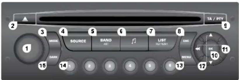
On/Off and volume adjustment.
2 CD eject.
3. Selection of the display on the screen from the modes: Audio (AUDIO), Vehicle Diagnostics and Telephone (TEL) functions.
4. Selection of the source: radio, audio CD/MP3 CD, CD changer, USB, Jack connection, Streaming
5. Selection of the FM1, FM2, FMast and AM wavebands.
6 Setting audio options: front/rear balance, left/right balance, loudness, sound ambiences
7. Display the list of local stations, of the tracks on the CD or of the MP3 directories
8. Abandon current operation.
9 TA (Traffic Announcement) function on/off. Long press: access to the PTY (Types of radio programme) mode
10 Confirmation
11. Automatic search for a lower/higher frequency Selection of previous/next CD, MP3 or USB track.
12 Selection of a lower/higher radio frequency
Selection of the previous/next CD.
Selection of the previous/next MP3 directory.
Selection of the previous/next USB equipment directory/genre/artist/playlist
13 Display the general menu.
14 Buttons 1 to 6
Selection of a stored radio station
Selection of a CD in the CD changer.
Long press: storing of a station.
- The DARK button changes the display on the screen to improve driving comfort at night. 1st press: lighting of the top banner only. 2nd press: displaying of a black screen. 3rd press: return to the standard display.
02 STEERING MOUNTED CONTROLS
STEERING MOUNTED CONTROLS


- Activation/deactivation of the Black Panel mode (night driving)
- Pick up an incoming call/hang up a call which is in progress Open the telephone menu and display the call list Long press: refuse an incoming call.

- Access to the short-cut menus in accordance with the display on the screen. Confirmation of the function selected from a menu. Rotation: Selection of the previous/next stored RADIO station. Selection of the previous/next CD or MP3 directory. Selection of the previous/next CD in the CD changer.
-
Abandon the current operation. Reject an incoming call. Long press: return to the main display.
-
Access to the main menu.
- Volume increase
- volume decrease.
- Mute.
- RADIO: automatic search for a lower/higher frequency. CD/MP3/CD CHANGER: selection of the previous/next track. continuous press: fast forward/rewind play.
- RADIO: display the list of stations available Long press: update the list of radio stations. CD/MP3/CD CHANGER: display the list of CD and directory tracks.
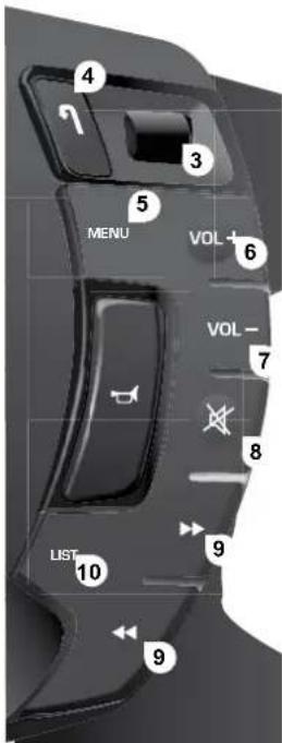
03 MAIN MENL
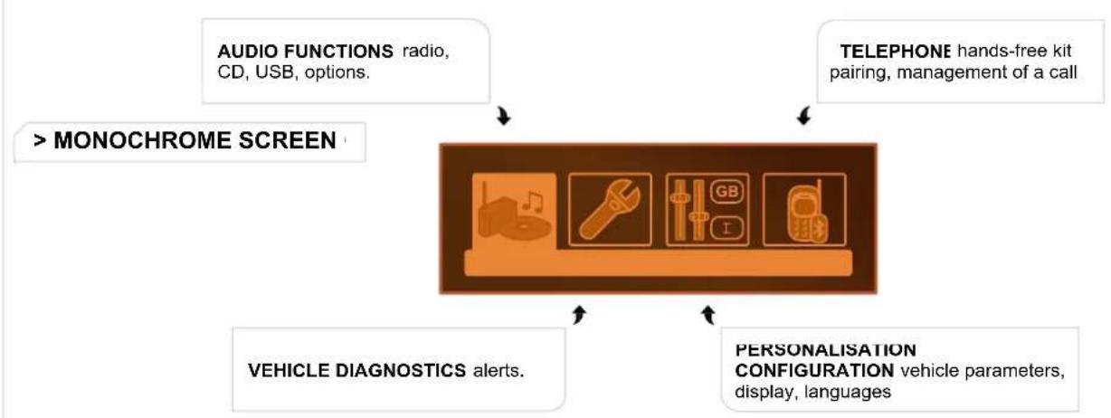
flowchart
graph TD
    A["AUDIO FUNCTIONS radio, CD, USB, options."] --> B["> MONOCHROME SCREEN"]
    C["TELEPHONE hands-free kit pairing, management of a call"] --> B
    D["VEHICLE DIAGNOSTICS alerts."] --> B
    E["PERSONALISATION CONFIGURATION vehicle parameters, display, languages"] --> B

04 AUDIC

RADIO SELECTING A STATIO
The external environment (hills, buildings, tunnels, basement car parks) may block reception, including in RDS mode. This is a normal effect of the way in which radio waves are transmitted and does not indicate any failure of the audio equipment!
| 1 |  | Press the SOURCE button severa times in succession and select the radio. |  |
| 2 |  | Press the BAND AST button to sele a waveband: FM1, FM2, FMast, AM |  |
| 3 |  | Briefly press one of the buttons carry out an automatic search of the radio stations. |  |
| 4 |  | Press one of the buttons to carry out manual search of the radio stations |  |
 | Press the LIST REFRESH button display the list of stations received locally (30 stations maximum) To update this list, press for more tha two seconds. |  |
RD
| 1 | Press the MENU buttor | |
| 2 | Select AUDIO FUNCTIONS the press OK | |
| 3 | Select the FM WAVEBAN PREFERENCES function then pres OK. | |
| 4 | Select ACTIVATE FREQUENCY FOLLOWING (RDS) then press OK RDS appears on the display |
The RDS, if displayed, enables you to continue listening to the sa station by automatic retuning to alternative frequencies. However, certain conditions, coverage of an RDS station may not be assure throughout the country as radio stations do not cover 100 % of the territory. This explains the loss of reception of the station during journey.
04 AUDIC
CE
PLAYING A C

Insert circular compact discs onl
Some anti-pirating systems, on original discs or CDs copied using personal recorder, may cause faults which are no reflection on the quality of the original player
Without pressing the EJECT button, insert a CD in the player, pl begins automatically
1

To play a disc which has already be inserted, press the SOURCE buttc several times in succession and sele CD.
2
Press one of the buttons to select track on the CD
!
Press the LIST REFRESH button to display the list of tracks on tr
3
Press and hold one of the buttons for fast forward or backward
MP3 CD
PLAYING AN MP3 COMPILATIO

Insert an MP3 compilation in the playe
The audio equipment searches for all of the music tracks, which must take anything between a few seconds and several tens of seconds before play begins

On a single disc, the CD player can read up to 255 MP3 fi les spre over 8 directory levels. However, it is advisable to keep to a limit two levels to reduce the access time before the CD is played. While the CD is being played, the directory flow chart is not followed. All of the fi les are displayed on a single level
1

To play a disc which has already been inserted, press the SOURCE button several times in succession and select CD.
2
Press one of the buttons to select track on the CD
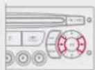
Press the LIST REFRESH button to display the list of directories the MP3 compilation
3
Press and hold one of the buttons for fast forward or backward play
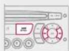
04 AUDIC
MP3 CD INFORMATION AND ADVIC

The MP3 format, an abbreviation of MPEG 1.2 & 2.5 Audio Layer is an audio compression standard which permits the recording several tens of music files on a single dis

In order to be able to play a recorded CDR or CDRW, when record it is preferable to select standards ISO 9660 level 1.2 or Jolie If the disc is recorded in another format, it may not be played correctly
It is recommended that the same recording standard is always used for an individual disc, with as low a speed as possible (4x maximum for optimum sound quality
In the particular case of a multi-session CD, the Joliet standard recommended

The audio equipment will only play fi les with the extension ".m with a sampling rate of 22.05 KHz or 44.1 KHz. No other type of fi (.wma, .mp4, .m3u...) can be played

It is advisable to restrict fi le names to 20 characters without us special characters (e.g. " " ? ; ü) to avoid any playing or displayin problems.
AUDIO/MP3 CD CHANGER PLAYING A C
1

Insert the CDs in a multi-slot change one by one.
On a single slot changer, pres LOAD, select the number of the CD then insert the CD, or press and hold LOAD and insert the CDs one by one Press the SOURCE button sever times in succession and selec CD CHANGER.
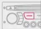
2
Press one of the buttons on the numeric keypad to select the corresponding CD
3
Press one of the buttons to select track on the CD Press and hold one of the buttons for fast forwards or rewind play
* according to availability on the vehi
05 USB BOX
USING THE USB BOX
1
This unit consists of a USB port and a Ja socket *. The audio fi les are transmitted from portable equipment such as a digital player or USB memory stick to your Audio system to be listened to via the vehicle's speakers
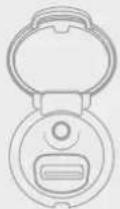
2
USB key (1.1, 1.2 and 2.0) or lpi® o generation 5 or later - USB memory sticks should be formatted F or FAT 32 (NTFS not supported); - the lpc® lead is essentia - navigation through the fi le database is means of the steering wheel controls - the IPod software should be regularly update for the best connection.
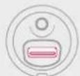
3
Other lpc ^® players of earlier generations an players using the MTP protocol - play via Jack-Jack lead only (not supplie - navigation through the file database is from portable equipment

The list of compatible equipment and the compression rates supported are available for CITROEN dealers
CONNECTING A USB MEMORY STIC
1
Connect the memory stick to the port, directly using a lead. If the audio equipment is switch on, the USB source is detected as soon as it connected. Play begins automatically after a del which depends on the capacity of the USB stic The fi le formats recognised are .mp3 (mpε layer 3 only), .wma (standard 9 only, 128 kbits/s compression), .wav and .ogc The playlists types accepted are m3u, .pls, .w
!
The system puts together playlists (temporary memory) created on a period which depends on the capacity of the USB equipment. The other sources are available during this time. The playlists are updated each time the ignition is switched off each time a USB memory stick is connected. When connecting for the fi rst time, the classification suggested is folder. When you reconnect, the classification selected previously retained
* According to vehic
05 USB BOX
USING THE USB POR
2
Press and hold LIST to display the different classifi cations Select by Folder/Artist/Genre/Playlis press OK to select the classifi catic required, then press OK again to confi rn
OK

- by Folder: all folders containing au fi les recognised on the peripher device, classified in alphabetical order without following the flow char
- by Artist: all of the artist nam defi ned in the ID3 Tags, classifi ed alphabetical order
- by Genre: all of the genres defi nec the ID3 Tags
- by Playlist: in accordance with tl playlists recorded on the USB device.
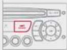
3

Press LIST briefl y to display t previously selected classifi cation Navigate through the list using th left/right and up/down buttons Conf i rm the selection by pressing OI
4
Press one of these buttons to ga access to the previous/next track or the classification list currently be in played.
Press and hold one of the buttons for fast forward or backward play
5

Press one of these buttons to ga access to the previous/next Genre Folder, Artist or Playlist on th classifi cation list currently bein played.
CONNECTING AN IPO® VIA THE USB PORT
1
The lists available are Artist, Genre and Playlist (as defined the iPoc®) Selection and Navigation are described in steps 1 to 5 above.
!
Do not connect a hard disk or USB devices other than audio equipment to the USB port. This could damage your installation.
05 USB BOX
USING THE AUXILIARY SOCKET (AUX) JACK SOCKET OR RCA SOCKET (according to veh

The auxiliary socket, JACK or RCA, permits the connection portable equipment (MP3 player...

Do not connect a single piece of equipment via the USB pc and the JACK socket at the same time

Connect the portable equipment (MP player...) to the JACK socket or to the audio sockets (white and red, RCA type) using a suitable cable (not supplied).


Press the SOURCE button several times in succession and select AUX
ADJUSTING THE VOLUME OF THE AUXILIARY SOURCE

First adjust the volume of your portable equipmer


Then adjust the volume of your audi equipment.

The controls are displayed and managed via the portable equipment
06 BLUETOOTH FUNCTIONS

BLUETOOTH TELEPHONE SCREEN C
PAIRING A TELEPHON

For safety reasons and because they require prolonged attention on the part of the driver, the operations for pairing of the Bluetooth mobile telephone with the Bluetooth hands-free system of your audio equipment must be carried out with the vehicle stationary and the ignition on
1
Activate the telephone's Bluetooth functic

2

Press the MENU butto
3
In the menu, selec
- Bluetooth telephone function - Au - Bluetooth confi gurati
Perform a Bluetooth search
4
A window is displayed with "Searching..
5
The first 4 telephones recognised are displayed in this window.
The services offered depend on the network, the SIM card and the compatibility of the Bluetooth equipment used.
Consult your telephone's manual and your operator to find out which services are available to you list of mobile telephones which offer the best range of services is available from the network. Consult a CITROËN dealer
! The TELEPHONE menu permits access to the following functions particular: Directory *, Call list, Pairing manageme
* If your telephone is fully compati
6 Select the telephone to be connected from the list. Only o telephone can be connected at a time
7 A virtual keypad is displayed on the screen a code with at least 4 digi Confir rm by pressing Ol
8 A message is displayed on the screen of t telephone chosen: to accept the pairing, ente the same code on the telephone, then confi rm b pressing OK.
9 If pairing fails, the number of attempts is not limited
"Pairing of Name_telephone successful" appears on the screen. The automatic connection authorised is only active after the telephone has been configured. The directory and the call list can be accessed after the synchronisation period
! The pairing can also be initiated from the telephone.
06 BLUETOOTH FUNCTIONS
RECEIVING A CAL
1 An incoming call is announced by a ring and a superimposed disp on the multifunction screen
Select the YES tab on the display using the buttons and confirm to pressing OK.

Press the steering mounted control OK to accept the call
MAKING A CAL
1 From the Bluetooth telephone function Audio menu, select Mana the telephone call then Call, Call list or Director
Press the end of the steering mounted control more than two seconds to gain access to you directory O To dial a number, use your telephone's keypad, w the vehicle stationary

BLUETOOTH AUDIO STREAMING (AVAILABLE DURING THE YEAR
! Wireless transmission of the telephone's music fi les via the au equipment. The telephone must be able to manage the appropriat bluetooth profi les (Profi les A2DP/AVRCI
1 Initiate the pairing between the telephone and vehicle. This pairing can be initiated from the vehicle telephone function menu or via the telephone's key. See steps 1 to 10 on the previous pages. During pairing phase, the vehicle must be stationary with key in the ignitio
2 Select the telephone to be connected from the telephone function menu. The audio system connects to a newly paired telephone automatic
3

Activate the streaming source b pressing the SOURCE button *. TI tracks to be played can be controlled as usual via the buttons on the Radi control panel and the steering wheel controls **. The contextual information can be displayed on the screen
* In certain cases, playing of the Audio fi les must be initiated from the ** If the telephone supports the funct
07 CONFIGURATION

SETTING THE DATE AND TIME SCREEN (
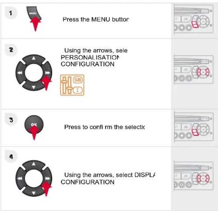
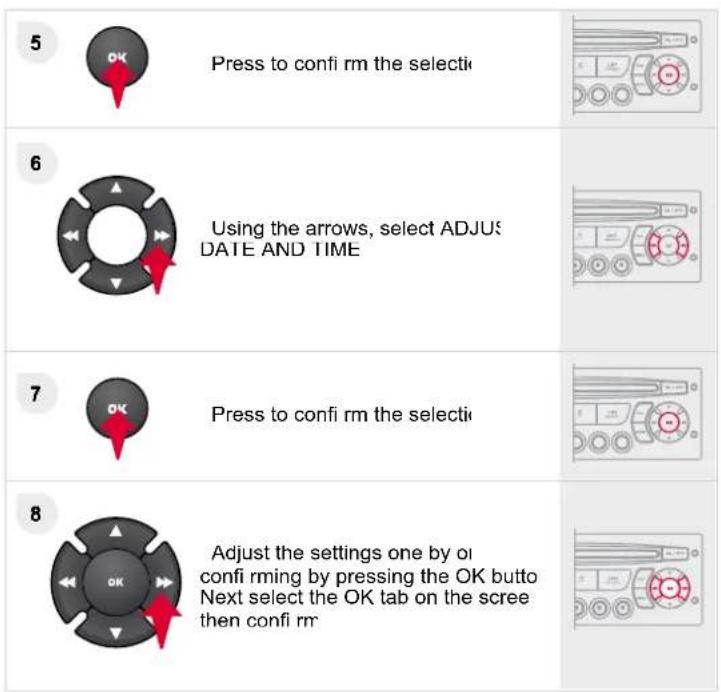
08 SCREEN MENU MAF
monochro
1 RADIO-C
RDS SEARC
REG MOD
2 CD REPEA
2 RANDOM PLA
VEHICLE CONFIC
REV WIPE AC
2 GUIDE LAMP
OPTION
DIAGNOSTIC
consu
3 abandon
UNIT
2 TEMPERATURE: °CELSIUS/°FAHRENHE
2 FUEL CONSUMPTION: KM/L - L/100 - MPG
* The parameters vary according to vehi

1 MAIN FUNCTION
2 CHOICE
3 Choice A
3 Choice A
2 CHOICE B.

DISPLAY ADJUS
2 YEAI
2 MONTI
2 DA
2 HOUI
2 MINUTE:
12 H/24 H MOD

LANGUAG
2 FRANCAI
2 ITALIAN
NEDERLAND:
PORTUGUE
2 PORTUGUES-BRASI
2 DEUTSCI
ENGLISI
2 ESPANO
monochrome C

Press the OK dial for access to short-ci menus according to the display on the screen:
RADI

activate/deactivate RD

activate/deactivate track repeat (the entire current CD CD or CD Changer, the entire current folder for MP3 CD MP3 Changer)

activate/deactivate random play (the entire current CD f CD or CD Changer, the entire current folder for MP3 CD all of the folders of the current CD for MP3 Changer)
US

activate/deactivate track repeat (of the current fold artist/genre/playlist)

activate/deactivate random play (of the current folk artist/genre/playlist)
08 SCREEN MENU MAF
monochro
1 RADIO-C
RDS SEARC
REG MOD
2 CD REPEA
2 RANDOM PLA
VEHICLE CONFIC
REV WIPE AC
2 GUIDE LAMP
OPTION
DIAGNOSTIC
consu
3 abandon
UNIT
2 TEMPERATURE: °CELSIUS/°FAHRENHE
2 FUEL CONSUMPTION: KM/L - L/100 - MPG
* The parameters vary according to vehi

1 MAIN FUNCTION
2 CHOICE
3 Choice A
3 Choice A
2 CHOICE B.

DISPLAY ADJUS
2 YEAI
2 MONTI
2 DA
2 HOUI
2 MINUTE:
12 H/24 H MOD

LANGUAG
2 FRANCAI
2 ITALIAN
NEDERLAND:
PORTUGUE
2 PORTUGUES-BRASI
2 DEUTSCI
ENGLISI
2 ESPANO
monochrome C

Press the OK dial for access to short-ci menus according to the display on the screen:
RADI

activate/deactivate RD

activate/deactivate track repeat (the entire current CD CD or CD Changer, the entire current folder for MP3 CD MP3 Changer)

activate/deactivate random play (the entire current CD f CD or CD Changer, the entire current folder for MP3 CD all of the folders of the current CD for MP3 Changer)
US

activate/deactivate track repeat (of the current fold artist/genre/playlist)

activate/deactivate random play (of the current folk artist/genre/playlist)
08 SCREEN MENU MAF
monochrome C
Pressing the MENU button display:

AUDIO FUNCTION
FM BAND PREFERENCE
alternative frequencies (RD:
activate/deactivat
regional mode (REC
activate/deactivat
radio-text information (RDTX)
activate/deactivat
PLAY MODE
album repeat (RP)
activate/deactivat
track random play (RDM
activate/deactivat

VEHICLE DIAGNOSTIC
ALERT LO

PERSONALISATION-CONFIGURATIC
DEFINE THE VEHICLE PARAMETERS*
DISPLAY CONFIGURATIC
video brightness adjustment
normal video
inverse video
brightness (- +) adjustmer
date and time adjustmen
day/month/year adjustmer
hour/minute adjustment
choice of 12 n/24 n mod
choice of uni
l/100 km - mpg - km.
Connect/Disconnect a devic
Telephone function
Audio Streaming function
Consult the paired devic
Delete a paired devik
Perform a Bluetooth search
CAL
Calls li:
Director
MANAGE THE TELEPHONE CAL
Terminate the current c:
Activate private mode
FREQUENTLY ASKED QUESTIONS
| QUESTIO | ANSWEF | SOLUTION |
| There is a difference in sound quality between the different audio sources (radio, CD...) | For optimum sound quality, the audio settings (Volume, Bass, Treb Ambience, Loudness) can be adapted to the different sound source which may result in audible differences when changing source (radi CD...). | Check that the audio settings (Volume, Bas Treble, Ambience, Loudness) are adapted t the sources listened to. It is advisable to se the AUDIO functions (Bass, Treble, Front-Rea Balance, Left-Right Balance) to the middl position, select the musical ambience "None and set the loudness correction to the "Active position in CD mode or to the "Inactive" positio in radio mode |
| The CD is ejecte automatically or is no played by the player | The CD is inserted upside down, is unplayable, does not contain any auc data or contains an audio format which the player cannot plaThe CD is protected by an anti-pirating protection system which is r recognised by the audio equipmen | - Check that the CD is inserted in the player right way up.- Check the condition of the CD: the CD canr be played if it is too damaged- Check the content in the case of a recorded (consult the advice in the "Audio" sectio- The audio equipment's CD player does r play DVDs.- Due to their quality level, certain writeable CI will not be played by the audio system. |
| The message "US peripheral error" is displayed on the screen | The Bluetooth connection is cuThe battery of the peripheral may not be suffi ciently charge | Recharge the battery of the peripheral device |
| The USB memory stick is not recogniseThe memory stick may be corrup | Reformat the memory stick | |
| The CD player sour is poor | The CD used is scratched or of poor qualit | Insert good quality CDs and store them i suitable conditions. |
| The audio equipment settings (bass, treble, ambiences) are unsuitab | Set the treble or bass level to 0, without selectir an ambience. | |
| The stored stations c not function (no sound 87.5 Mhz is displayed...) | An incorrect waveband is selected | Press the BAND AST button to return to the waveband (AM, FM1, FM2, FMAST) on which the stations are stored |
| The traffic announcer (TA) is displayed. I do not receive any traffic information | The radio station is not part of the regional traffic information netwc | Tune to a radio station which broadcasts traffic information |
| The quality of receptive of the radio station listened to gradually deteriorates or the stored stations dc not function (nc sound, 87.5 Mhz is displayed...) | The vehicle is too far from the transmitter used by the station listened to there is no transmitter in the geographical area through which the vehic is travelling. | Activate the RDS function to enable the system to check whether there is a more powerful transmitter in the geographical area |
| The environment (hills, buildings, tunnels, basement car parks...) blo reception, including in RDS mode | This phenomenon is normal and does no indicate a failure of the audio equipment | |
| The aerial is absent or has been damaged (for example when goir through a car wash or into an underground car park | Have the aerial checked by a CITROËN deals | |
| Sound cut-outs of to 2 seconds in radic mode. | During this brief sound cut-out, the RDS searches for any frequent permitting better reception of the station | Deactivate the RDS function if the phenomenon is too frequent and always on the same route |
| With the engine of the audio equipment switches off after a few minutes of use. | When the engine is switched off, the audio equipment operating tin depends on the battery chargeThe switch-off is normal: the audio equipment switches to economy mode and switches off to prevent discharging of the vehicle's batter | Start the vehicle's engine to increase the batte charge. |
| The message "the audio system is overheated" appears on the display | In order to protect the installation if the surrounding temperature is too high the audio equipment switches to an automatic thermal protection motor leading to a reduction of the volume or stopping of the playing of the C | Switch the audio system off for a few minutes allow the system to cool |
ACCESS
Unlocking
Press button A again to unlock the vehicle.
The red indicator lamp on the button switches off.
If the vehicle is locked or deadlocked from the outside, the red indicator lamp fl ashes and button A is inactive.
In this case, use the remote control or the key to unlock the vehicle.
Automatic central locking
System which provides full automatic locking or unlocking of the doors and the boot while driving.
You can activate or deactivate this function.
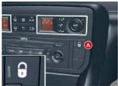
Locking
When the speed exceeds 6 mph (10 km/h), the doors and the boot lock automatically.
If one of the doors is open, the automatic central locking does not take place.
If the boot is open, the automatic central locking of the doors is active.
Unlocking
Above 6 mph (10 km/h), press button A to unlock the doors and the boot temporarily.
Activation
Press button A for more than two seconds.
A confirmation message appears on the instrument panel screen, accompanied by an audible signal.
Deactivation
Press button A again for more than two seconds.
A confirmation message appears on the instrument panel screen, accompanied by an audible signal.
Emergency control
To lock or unlock the doors manually in the event of a malfunction of the central locking system or battery failure.
Locking the driver's door
Insert the key in the lock, then turn it to the right.
Unlocking the driver's door
Insert the key in the lock, then turn it to the left.
Locking the front and rear passenger doors
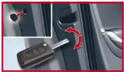
natural_image
Close-up of a car key inserted into the dashboard, showing red motion arrows indicating rotation (no text or symbols)Remove the black cap, located on the edge of the door, using the key.
Insert the key in the socket, then turn it as far as it will go.
Remove the key and refit the cap.
On the rear doors, check that the child lock is not activated.
Unlocking the front and rear passenger doors
Pull the interior door opening control.
ACCESS
Quality of the fuel used for petrol engines
The petrol engines are perfectly compatible with E10 type petrol biofuels (containing 10% ethanol), conforming to European standards EN 228 and EN 15376.
E85 type fuels (containing up to 85 % ethanol) are reserved exclusively for vehicles marketed for the use of this type of fuel (BioFlex vehicles). The quality of the ethanol must comply with European standard EN 15293.
For Brazil only, special vehicles are marketed to run on fuels containing up to 100 % ethanol (E100 type).
Quality of the fuel used for Diesel engines
The Diesel engines are perfectly compatible with biofuels which conform to current and future European standards (Diesel fuel which complies with standard EN 590 mixed with a biofuel which complies with standard EN 14214) available at the pumps (containing up to 7% Fatty Acid Methyl Ester).
The B30 biofuel can be used in certain Diesel engines; however, this use is subject to strict application of the special servicing conditions. Consult a CITROËN dealer.
The use of any other type of (bio)fuel (vegetable or animal oils, pure or diluted, domestic fuel...) is strictly prohibited (risk of damage to the engine and fuel system).
MISFUEL PREVENTION
Mechanical device which prevents filling the tank of a Diesel vehicle with petrol. It avoids the risk of engine damage that can result from filling with the wrong fuel.
Located in the filler neck, the misfuel prevention device appears when the filler cap is removed.
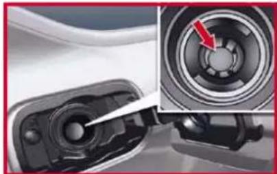
natural_image
Close-up of a mechanical component with a highlighted circular feature and red arrow indicating direction (no text or symbols)Operation
When a petrol filler nozzle is introduced into the fuel filler neck of your Diesel vehicle, it comes into contact with the flap. The system remains closed and prevents filling.
Do not persist but introduce a Diesel type fi Iler nozzle.
The device allows filling from a fuel can.
In order to ensure a good flow of fuel, do not place the nozzle of the fuel can in direct contact with the flap of the misfuel prevention device.
DRIVING
The electric parking brake combines 2 operational modes:
- AUTOMATIC
Automatic application when the engine stops and automatic release on use of the accelerator (automatic operation by default), MANUAL
Manual application/release of the parking brake is always possible by pulling control A while pressing the brake pedal.
Automatic operation
Application with the engine off
With the vehicle stationary, the parking brake is automatically applied when the engine is switched off.
The application of the parking brake is confirmed by:

- the lighting of the warning lamp on control A and on the instrument panel,
- the display of a message "hand-brake on" on the instrument panel screen.
The noise of operation will confirm to you the application/release of your electric parking brake.

Before leaving the vehicle, check that warning lamp P on the instrument panel is permanently lit.
Never leave a child alone inside the vehicle with the ignition on, as they could release the parking brake.
Application with the engine running
With the engine running and the vehicle stationary, in order to immobilise the vehicle you need to manually apply the parking brake by pulling on control A.
The application of the parking brake is confirmed by:

- the lighting of warning lamp P on control A and on the instrument panel,
- the display of a message "hand-brake on" on the instrument panel screen.
When the driver's door is opened, a beep is heard and a message displayed if the parking brake has not been applied.

Before leaving the vehicle, check that warning lamp P on the instrument panel is permanently lit.
DRIVING
Release
The electric parking brake releases automatically and progressively when you press the accelerator:
with a manual gearbox (first gear or reverse gear engaged), press down fully on the clutch pedal then press on the accelerator pedal and move off.
with an automatic gearbox, accelerate with the selector in position D, M or R.
Full release of the parking brake is confirmed by:

- the warning lamp P on control A and on the instrument panel going out,
- the display of a message "hand-brake off" on the instrument panel screen.
When stationary, with the engine running, do not press the accelerator pedal unnecessarily (particularly when starting the engine, including in neutral), as you may release the parking brake.
Activation/Deactivation of the automatic functions
Depending on the country of sale, automatic application when switching off the engine and automatic release when moving off can be deactivated. The activation/deactivation is done in the instrument panel screen configuration menu. Select "Vehicle parameters/Comfort/Auto handbrake".

Deactivation of these functions is signalled by this warning lamp in the instrument panel.
With the automatic functions deactivated, the parking brake must be applied and released manually.
! Deactivation of the automatic functions is recommended in very cold weather (freezing) and when towing (recovery, caravan...).
If the configuration menu does not have the option to activate/deactivate the automatic functions, this can be done by a CITROËN dealer.
Manual operation
Manual application/release of the parking brake is always possible.
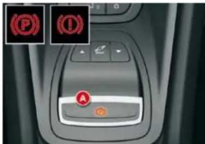
Application
With the vehicle stationary, to apply the parking brake whether the engine is running or off, pull on control A.
The application of the parking brake is confirmed by:

the lighting of the warning lamp on control A and of warning lamp P on the instrument panel,
- the display of a message "handbrake on" on the instrument panel screen.
When the driver's door is opened with the engine running, a beep is heard and a message displayed if the parking brake has not been applied.
FITTINGS
SUN VISOR
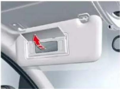
natural_image
Close-up of a car interior showing a white plastic door with a red arrow pointing to the center (no text or symbols visible)With the ignition on, lift the flap; the mirror is illuminated automatically.
To prevent dazzle from ahead, fold the visor downwards.
It can be disengaged from its central fixing and pivoted over to the side windows if required.
COOLED GLOVE BOX
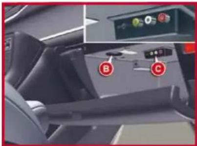
To open the glove box, pull on the handle and lower the lid.
The glove box has a manually closable air conditioning vent B.
It has 2 or 3 sockets C to connect audio/video equipment, and a slot for a SIM card (see "Audio and Telematics" section).
It has automatic illumination.
SKI FLAP

natural_image
Interior view of a car seat with silver leather seats and a black seat, no visible text or symbolsA flap in the backrest, located to the rear of the armrest, facilitates the carrying of long objects.
To open
Lower the rear armrest.
Pull the fl ap handle down.
Lower the flap.
Load the objects from inside the boot.

Whilst driving, the glove box should be kept closed.
Ensure that the objects are well secured and that they do not impede the operation of the gear lever.
TECHNICAL DATA
| MODELS: | ENGINES AND GEARBOXES | ||||
| Model codes:RD... RW... | 6FYC | RFJC/FF | 5FV-5FN | XFVJ | |
| PETROL ENGINES | 1.8 litre 16V | Biofl ex 2 litre 16V | 1.6 litre THP 155 | 3 litre V6 | |
| Cubic capacity (cc) 1 749 1 997 | 1 598 2 946 | ||||
| Bore x stroke (mm) 82.7 x 81.4 | 85 x 88 | 77 x 85.8 | 87 x 82.6 | ||
| EU standard maximum power (kW)/hp DIN | 92/127 | 103/143 | 115/159 | 155/215 | |
| Maximum power engine speed (rpm) | 6 000 | 6 000 6 000 | 6 000 | ||
| EU standard maximum torque (Nm) | 170 | 200 | 240 | 290 | |
| Maximum torque engine speed (rpm) | 3 750 | 4 000 1 400 | 3 750 | ||
| Fuel | Unleaded | Unleaded/E85 | Unleaded | Unleaded | |
| Catalytic converter | Yes | Yes | Yes | Yes | |
| GEARBOXES | Manual(5-speed) | Manual(5-speed) | Auto.(6-speed) | Manual(6-speed) | Auto.(6-speed) |
| OIL CAPACITIES (in litres) | |||||
| Engine (with filter replacement) | 5 | - | 4.2 | 4.2 | 4.75 |
| Gearbox - Final drive | - | - | - | - | - |
XII
TECHNICAL DATA
| WEIGHTS AND TOWED LOADS (SALOON) in kg | |||||
| Petrol engines | 1.8 litre 16V | Biofl ex2 litre 16V | 1.6 litre THP 155 | 3 litre V6 | |
| Gearboxes | Manual | Manual | Auto. | Manual | Auto. |
| Model codes:RD... | 6FYC | RFJC/FF | 5FV-5FN | XFVJ | |
| - Unladen weight | 1 510 | 1 521 | 1 515 | 1 471 | 1 725 |
| - Kerb weight | 1 585 | 1 596 | 1 590 | 1 546 | 1 800 |
| - Gross vehicle weight (GVW) | 2 015 | 2 063 | 2 026 | 2 065 | 2 230 |
| - Gross train weight (GTW) | 3 315 | 3 563 | 3 526 | 3 565 | 3 630 |
| - Braked trailer(within GTW limit)on a 10 % or 12 % gradient | 1 300 | 1 500 | 1 500 | 1 500 | 1 400 |
| - Braked trailer * (with loadtransfer within GTW limit) | 1 530 | 1 720 | 1 710 | 1 730 | 1 650 |
| - Unbraked trailer | 750 | 750 | 750 | 750 | 750 |
| - Recommended nose weight | 62 | 69 | 69 | 70 | 66 |
* The weight of the braked trailer can be increased, within the GTW limit, on condition that the GVW of the towing vehicle is reduced by the same amount; warning, towing with a lightly loaded towing vehicle may have an adverse effect on its road holding.
The GTW and towed load values indicated apply up to a maximum altitude of 1,000 metres; the towed load mentioned must be reduced by 10% for each additional 1,000 metres of altitude.
The speed of a towing vehicle must not exceed 100 km/h (approx. 60 mph) (comply with the legislation in force in your country).
High ambient temperatures may result in a reduction in the performance of the vehicle in order to protect the engine; when the ambient temperature is higher than 37 °C , limit the weight towed.
XII
TECHNICAL DATA
| WEIGHTS AND TOWED LOADS (TOURER) in kg | |||||
| Petrol engines | 1.8 litre 16V | Biofl ex 2 litre 16V | 1.6 litre THP 155 | 3 litre V6 | |
| Gearboxes | Manual | Manual | Auto. | Manual | Auto. |
| Model codes: RW... | 6FYC | RFJC/FF | 5FV-5FN | XFVJ | |
| - Unladen weight | 1 549 | 1 578 | 1 534 | 1 503 | 1 761 |
| - Kerb weight | 1 624 | 1 653 | 1 609 | 1 578 | 1 836 |
| - Gross vehicle weight (GVW) | 2 154 | 2 183 | 2 200 | 2 167 | 2 366 |
| - Gross train weight (GTW) | 3 454 | 3 683 | 3 700 | 3 667 | 3 666 |
| - Braked trailer (within GTW limit) on a 10 % or 12 % gradient | 1 300 | 1 500 | 1 500 | 1 500 | 1300 |
| - Braked trailer * (with load transfer within GTW limit) | 1 600 | 1 790 | 1 790 | 1 790 | 1 600 |
| - Unbraked trailer | 750 | 750 | 750 | 750 | 750 |
| - Recommended nose weight | 64 | 72 | 74 | 73 | 68 |
* The weight of the braked trailer can be increased, within the GTW limit, on condition that the GVW of the towing vehicle is reduced by the same amount; warning, towing with a lightly loaded towing vehicle may have an adverse effect on its road holding.
The GTW and towed load values indicated apply up to a maximum altitude of 1,000 metres; the towed load mentioned must be reduced by 10% for each additional 1,000 metres of altitude.
The speed of a towing vehicle must not exceed 100 km/h (approx. 60 mph) (comply with the legislation in force in your country).
High ambient temperatures may result in a reduction in the performance of the vehicle in order to protect the engine; when the ambient temperature is higher than 37^ , limit the weight towed.
- Door mirrors
- Adjustment
- Folding
- Unfolding
- Rear view mirror
- Day/night position
- COMFORT
- on
- Off
- STEERING WHEEL ADJUSTMENT
- MONITORING
- INSTRUMENT PANELS - PETROL AND DIESEL - MANUAL AND AUTOMATIC GEARBO)
- Main menu
- "Choice of units" menu
- "Choice of language" menu
- "Vehicle parameters" menu
- "Lighting" menu
- "Comfort" menu
- TRIP COMPUTER
- A few definitions...
- Return to the main instrument panel screen display
- Log of alerts
- Display of navigation information on instrument panel screen
- Indicator and warning lamps
- When the ignition is switched on
- Associated warnings
- Operation indicator lamps
- Deactivation indicator lamps
- Warning lamps
- Service indicator
- More than 620 miles (1 000 km) remain before the next service is due
- Less than 620 miles (1 000 km) remain before the next service is due
- Service overdue
- Service indicator zero reset
- Engine oil level indicator Oil level gauge fault
- Oil level correct
- Oil level low
- Total distance recorder
- Trip distance recorder
- Lighting rheostat
- Operation
- Deactivation
- MULTIFUNCTION SCREENS
- MONOCHROME SCREEN C
- Presentation
- Time
- Controls
- Personalisation - Configuration
- Radio-CD
- Bluetooth® system
- Adjusting the brightness and contrast
- Adjusting the date and the time
- Choosing the units
- Selection of the type of information displayed (Mode)
- Displays on the screen
- System language
- Date & time
- Units
- System
- Display
- 16/9 HIGH DEFINITION COLOUR SCREEN (WITH NAVIDRIVE 3D)
- "SETUP" menu
- Language & Speech
- VENTILATION
- HEATING, VENTILATION AND AIR CONDITIONING RECOMMENDATIONS
- Air conditioning
- Air inlet
- Air circulation
- Dust filter/Odour filter (active carbon)
- DIGITAL AIR CONDITIONING (MONO-ZONE)
- Automatic operation
- Temperature adjustment
- Control via the manual controls
- Air distribution adjustment
- Air conditioning
- Air flow adjustment
- Switching off the ventilation
- To reactivate the air conditioning:
- Front demisting - defrosting
- Rear demisting - defrosting
- Intake of exterior air/Recirculation of interior air
- DIGITAL AIR CONDITIONING (DUAL-ZONE)
- 1a-1b. Automatic operation
- 2a-2b. Temperature adjustment
- 3a-3b. Air distribution adjustment
- Reducing the flow to minimum switches the air conditioning OFF.
- Air recirculation - intake of exterior air
- Closing the air intake
- Air conditioning
- Intake of exterior air
- Rear demisting - defrosting
- Front demisting - defrosting
- Programming remote control
- Programming the heating
- Programming the departure time
- Activation - deactivation
- Switching off the heating
- Changing the level of heating
- Changing the battery
- Reinitialising the remote control
- FRONT SEATS
- MANUAL ADJUSTMENTS
- ELECTRIC ADJUSTMENTS
- Adjustment of the seat height and angle, and longitudinal adjustment
- Adjustment of the backrest angle
- Adjustment of the angle of the top of the backrest
- Adjustment of lumbar support
- Head restraint height and angle adjustments on electric seats
- Heated seats control
- Massage function The Welcome function
- Storing driving positions
- Storing a position
- Using buttons M/1/2
- Recalling a stored position
- Ignition on or engine running
- REAR HEAD RESTRAINTS
- REAR SEATS
- Removing the seat cushion
- Refitting the seat cushion
- Folding the seat
- Returning the seat back to its original position
- MIRRORS
- STEERING WHEEL ADJUSTMEN
- OPENINGS
- REMOTE CONTROL KEY
- Unfolding the key
- Complete unlocking using the remote control
- Complete unlocking using the key
- Selective unlocking using the remote control
- Electric boot opening
- Locking the vehicle
- Normal locking using the remote control
- Normal locking using the key
- Deadlocking using the remote control
- Deadlocking using the key
- Locating your vehicle
- Guide-me-home lighting
- Anti-theft protection
- Electronic engine immobiliser
- SERVICE
- IGNITION SWITCH
- "S": Steering lock
- "M": Drive position
- "D": Starter
- Steering lock
- STOPPING
- Vehicles equipped with a turbocharger
- Malfunction
- Reinitialisation
- Lost keys
- Remote control
- When purchasing a second-hand vehicle
- ALARM
- Exterior perimeter
- - Interior volumetric
- - Tilt
- Self-protection function
- Locking the vehicle with full alarm system
- Activation
- Locking the vehicle with exterior perimeter monitoring only
- Deactivation of the interior volumetric and anti-lift monitoring
- Reactivation of the interior volumetric and anti-lift monitoring
- Triggering of the alarm
- Failure of the remote control
- Locking the vehicle without activating the alarm
- Automatic activation \*
- ELECTRIC WINDOWS
- One-touch electric windows
- Safety anti-pinch
- Deactivation of the rear electric window and door controls
- DOORS
- Opening
- From inside
- Manual centralised control
- Locking
- Unlocking
- Automatic central locking
- Emergency control
- Locking the driver's door
- Unlocking the driver's door
- Unlocking the front and rear passenger doors
- BOOT (SALOON)
- Locking/unlocking
- Emergency tailgate release
- BOOT (TOURER)
- Manual opening
- Electric opening
- Manual closing
- Electric closing
- Interrupting the opening/closing of the tailgate
- Memorisation of an intermediate position
- Cancelling the memorisation
- Electrical protection of the motor
- PANORAMIC SUN (SALOON)
- Sunroof closed
- Sunroof open
- Tilted sunroof
- Anti-pinch
- Closing
- FUEL TANK
- Low fuel level
- Opening the fuel flap
- Refuelling
- Quality of the fuel used for petrol engines
- Quality of the fuel used for Diesel engines
- VISIBILITY
- EXTERIOR LIGHTING CONTROLS
- Main lighting
- Programming
- Additional lighting
- Displays
- Lamps on buzzer
- Daytime-running lamps
- Manual guide-me-home lighting
- Switching on
- Switching off
- Automatic illumination of headlamps
- Linked with the automatic "Guide-me-home" lighting
- Operating fault
- MANUAL HEADLADJUSTMENT
- AUTOMATIC ADJUSTMENT OF DIRECTIONAL HEADLAMPS
- DIRECTIONAL LIGHTING
- "Cornering lighting" function
- Directional headlamps function
- WIPER CONTROLS
- Manual controls
- Windscreen wipers
- Reverse gear
- Windscreen and headlamp wash
- Automatic rain sensitive windscreen wipers
- Special position of the windscreen wipers
- COURTESY LAMPS
- Front courtesy lamp
- Rear courtesy lamp
- Map reading lamps
- Panoramic sunroof rear reading lamps (Tourer)
- INTERIOR MOOD LIGHTING
- Central console
- Lighting for door opening controls
- WELCOME LIGHTING
- FITTINGS
- SUN VISOR
- COOLED GLOVE BOX
- SKI FLAP
- To open
- MATS
- Removing
- Refitting
- FRONT ARMREST
- Cup-holder/USB port
- Cup-holder
- Storage
- BOOT FITTINGS (SALOON)
- Luggage securing rings
- BOOT FITTINGS (TOURER)
- Hook
- Torch
- Luggage-cover blind
- Luggage securing rings
- Hooks
- Boot lamp
- Loading height control
- Hook
- Installation
- CHILD SAFETY
- GENERAL POINTS RELATING TO CHILD SEATS
- CHILD SEAT IN THE FRONT
- "Rearwards-facing"
- "Forwards-facing"
- CHILD SEATS RECOMMENDED BY CITROËN
- POSITIONS FOR CHILD SEATS SECURED USING THE SEAT BELT
- "ISOFIX" MOUNTINGS
- Saloon
- Tourer
- ADVICE ON CHILD SEATS
- Installing a booster seat
- ISOFIX CHILD SEAT RECOMMENDED BY CITROËN AND APPROVED FOR YOUR VEHICLE
- POSITIONS FOR FITTING ISOFIX CHILD SEATS
- ELECTRIC CHILD LOCK
- SAFETY
- DIRECTION INDICATORS
- "Motorway" function
- HAZARD WARNING LAI
- Automatic operation of hazard warning lamps
- HORN
- TYRE UNDER-INFLATION DETECTION
- Choice of detection
- Automatic detection
- Driver request detection
- Tyres OK display
- Under-inflated tyre
- Automatic detection:
- Driver request detection:
- Anti-lock braking system and electronic brake force distribution
- Emergency braking assistance
- Anti-skid regulation (ASR) and electronic stability programme (ESP)
- Intelligent traction control (Snow Motion)
- Reactivation
- SEAT BELTS
- Front seat belts
- Fastening
- Unfastening
- Recommendations for children
- In the event of an impact
- AIRBAGS
- The airbags do not operate when the ignition is switched off.
- Impact detection zones
- Front airbags
- Lateral airbags \*
- Curtain airbags \*
- For the airbags to be fully effective, observe the following safety rules:
- Lateral airbags
- Curtain airbags
- DRIVING
- Application
- Release
- - AUTOMATIC
- Automatic operation
- Application with the engine off
- Application with the engine running
- Activation/Deactivation of the automatic functions \*
- Manual operation
- Maximum application
- Maximum application is essential:
- Particular situations
- Dynamic emergency braking
- Emergency parking brake release
- Operating anomalies
- HILL START ASSIST
- 5-SPEED MANUAL GEARI
- Starting the vehicle
- Engaging reverse gear
- GEAR ECONOMY INDICATOR
- AUTOMATIC GEARBOX
- Mode selection Displays on the instrument panel
- Moving off
- Park
- Neutral
- SNOW programme " \* "
- Return to automatic operation
- SPORT programme "S"
- FIXED CENTRED CONTROLS STEERING WHEEL
- SPEED LIMITER
- Overriding the programmed speed
- Return to normal driving
- CRUISE CONTROL
- Displays on the instrument panel
- Adjustment of the memorised speed while cruise control is in operation
- Suspension/Resumption
- LANE DEPARTURE WARNING SYSTEM
- Detection
- PARKING SPACE SENSOR
- VISUAL AND AUDIBLE FRONT AND/OR REAR PARKING SENSORS
- Display on the instrument panel
- Normal mode
- SPORT mode
- Position not authorised
- CHECKS
- BONNET
- BLEEDING THE DIESEL FUEL FILTER
- HDi 140 engine
- HDi 110, HDi 163 and V6 HDi 240 engines
- Refi tting
- Bleeding water from the fuel filter
- Priming the fuel system
- V6 HDi 240 engine with electric pump
- PETROL ENGINES
- litre V6 petrol engine
- DIESEL ENGINES
- HDi 163 - V6 HDi 240 engines (with particle filter)
- The Diesel fuel system being under high pressure:
- CHECKING LEVELS
- Oil level
- Dipstick
- Oil change
- Oil specifi cation
- Brake fluid level
- Fluid change
- Fluid specifi cation
- Power steering fluid or power steering and suspension fluid level
- Coolant level
- On vehicles which are fitted with a particle emission filter, the fan may operate after the vehicle has been switched off, even if the engine is cold.
- Coolant change
- Screenwash and headlamp wash fluid
- Diesel additive level (Diesel engine with particle emission filter)
- Topping up
- Used products
- Battery
- Air filter and passenger compartment filter
- Oil filter
- Particle filter system (Diesel)
- Manual gearbox
- Brake disc wear
- Parking brake
- Brake pads
- PRACTICAL INFORMATION
- TEMPORARY PUNCTURE REPAIR KIT
- Using the kit
- CHANGING A WHEEL
- List of tools
- Access to the spare wheel
- To remove the spare wheel
- To reposition the spare wheel
- Before positioning the jack:
- Wheel for temporary use
- Fitting a wheel
- Deflation detection
- Security bolts
- CHANGING A BULB
- Headlamps
- Model with Xenon headlamps (D1S)
- Risk of electrocution
- Sidelamps
- Model with halogen headlamps
- Main beams
- Dipped beam
- Directional lamp
- Rear lamps (TourerBoot-mounted lamps
- Map reading lamp
- CHANGING A FUSE
- Replacing a fuse
- Fuses under the dashboard
- Access to the fuses
- Charging the battery using a battery charger
- Before disconnecting the battery
- Following reconnection of the battery
- ENERGY ECONOMY MODE
- Switching to economy mode
- Exiting economy mode
- TOWING THE VEHICLE
- TOWING A TRAILER, A CARAVAN, ETC
- Driving advice
- Distribution of loads
- Side wind
- Cooling
- Braking
- Tyres
- Lighting
- ROOF BARS
- Recommendations
- VERY COLD PROTECTION
- Normal position
- Snow position
- COLD CLIMATE SCRE
- Fitting
- Remove
- ACCESSORIES
- TECHNICAL DATA
- IDENTIFICATION MARKINGS
- VIN plate
- VIN stamped on body
- VIN on dashboard
- Paint colour code and tyre reference
- Tyre pressures
- EMERGENCY OR ASSISTANCE CALL
- EMERGENCY CAL
- ASSISTANCE CAL
- EMERGENCY OR ASSISTANCE CALL using NaviDrive
- EMERGENCY CALL
- ASSISTANCE CALL
- NaviDrive 3D
- CONTENT:
- FIRST STEPS
- NaviDrive 3D CONTROL PANEL
- FIRST STEPS NaviDrive 3D NAVIGATO
- VOICE COMMANDS AND STEERING MOUNTED CONTRO
- C5 STEERING MOUNTED CONTROL
- VOICE COMMANDS AND STEERING WHEEL CONTROL
- VOICE COMMANDS - VOIC RECO. INITIATIO
- DISPLAY ACCORDING TO THE CONTEXT
- NAVIGATION
- SETUI
- TRAFFIC
- MEDI
- NAVIGATION (IF GUIDANCE IS IN PROGRESS)
- MUSIC MEDIA PLAYER:
- RADIC
- DISPLAY ACCORDING TO THE CONTEX
- FULL SCREEN MAI
- AUDIO DVD (LONG PRESS
- VIDEO DVD (LONG PRESS
- NAVIGATION - GUIDANCI
- SELECTING A DESTINATION
- ROUTE OPTION
- ADDING A STOPOVE
- SEARCHING FOR POINTS OF INTERES (POI)
- US
- LIST OF PRINCIPAL POINTS OF INTEREST (PO
- SPOKEN INSTRUCTION SETTING
- POINTS OF INTEREST AND RISK AREA SETTINGS
- TRAFFIC INFORMATION
- CONFIGURE THE FILTERING AND DISPLAYING OF THE TMC MESSAGES
- PRINCIPAL TMC SYMBOLS
- 1
- 2
- RECEIVING TA MESSAGES
- i
- 3
- RADIC
- SELECTING A STATION
- RDS - REGIONAL MOD
- RENAMING OR DELETING AN ALBUI
- JUKEBOX
- USING AN EXTERNAL DEVICE (AUX) AUDIO/VIDEO/RCA CABLE NOT SUPPLIED
- USING THE TELEPHONE
- CHOOSING BETWEEN THE BLUETOOTH TELEPHONE/INTERNAL TELEPHONE
- CONNECTING A BLUETOOTI TELEPHONE
- USING THE INTERNAL TELEPHONE WITH SIM CARD
- RECEIVING A CAL
- MAKING A CAL
- CONFIGURATION
- SETTING THE DATE AND TIME
- SCREEN MENU MAF
- "TRAFFIC" MEN
- MyWay
- FIRST STEPS MyWay CONTROL PANE
- STEERING MOUNTED CONTROLS
- TRAFFI
- NAVIGATION SETTING
- UPDATING THE RISK AREAS POI
- TRAFFIC INFORMATIC
- CONFIGURE THE FILTERING AND DISPLAY OF TMC MESSAGES
- RDS - REGIONAL MODE
- CD CHANGER
- PLAYING A CD (NOT MP3/WMA COMPATIBLE
- BLUETOOTH TELEPHONE
- CONNECTING A TELEPHONE
- !
- #
- 4
- Audio System
- STEERING MOUNTED CONTROLS
- MAIN MENL
- AUDIC
- RADIO SELECTING A STATIO
- RD
- CE
- PLAYING A C
- MP3 CD
- PLAYING AN MP3 COMPILATIO
- MP3 CD INFORMATION AND ADVIC
- AUDIO/MP3 CD CHANGER PLAYING A C
- USB BOX
- USING THE USB BOX
- CONNECTING A USB MEMORY STIC
- USING THE USB POR
- 5
- CONNECTING AN IPO® VIA THE USB PORT
- USING THE AUXILIARY SOCKET (AUX) JACK SOCKET OR RCA SOCKET (according to veh
- ADJUSTING THE VOLUME OF THE AUXILIARY SOURCE
- BLUETOOTH FUNCTIONS
- BLUETOOTH TELEPHONE SCREEN C
- PAIRING A TELEPHON
- BLUETOOTH AUDIO STREAMING (AVAILABLE DURING THE YEAR
- CONFIGURATION
- SETTING THE DATE AND TIME SCREEN (
- SCREEN MENU MAF
- monochro
- monochrome C
- RADI
- ACCESS
- Locking the front and rear passenger doors
- MISFUEL PREVENTION
- Activation/Deactivation of the automatic functions
Brand : CITROEN
Model : C5 Dag (2009)
Category : Automotive