Glass FI-60GEVT /F-CM - Oven Smalvic - Free user manual and instructions
Find the device manual for free Glass FI-60GEVT /F-CM Smalvic in PDF.


| Product Type | Built-in Gas Oven with Electric Grill |
| Brand | Smalvic |
| Model | Glass FI-60GEVT /F-CM |
| Dimensions (WxHxD) | 59.5 x 59.5 x 55 cm |
| Weight | 30 kg |
| Power Supply | 220-230-240 V ~ 50/60 Hz |
| Total Electrical Power | 2.2 kW |
| Electric Grill Power | 1.8 kW |
| Oven Fan Power | 25 W |
| Tangential Fan Power | 25 W |
| Oven Light Bulb | 25 W, E14, 220-230 V |
| Oven Volume | 56 liters |
| Grill Cooking Area | 726 cm² |
| Gas Burner Oven Power (Natural Gas G20) | 2.20 kW |
| Gas Burner Grill Power (Natural Gas G20) | 2.10 kW |
| Gas Supply Pressure (Natural Gas) | 20 mbar |
| Functions | Oven burner, Grill burner, Electric grill, Ventilated electric grill, Fan only (defrost), Spit |
| Controls | Thermostat knob, Functions selector, Electronic clock, Mechanical timer |
| Timer | Electronic up to 10 hours, Mechanical up to 60 minutes |
| Safety Features | Flame safety device (thermocouple), Door safety switch, Overheat protection |
| Door | Removable, double-glazed |
| Cleaning | Manual cleaning with warm water and neutral detergent; avoid abrasives |
| Installation | Built-in; requires cabinet ventilation, gas and electrical connections |
| Accessories Included | Drip pan, internal grills |
| Energy Consumption (Natural Gas) | 210 l/h |
Frequently Asked Questions - Glass FI-60GEVT /F-CM Smalvic
User questions about Glass FI-60GEVT /F-CM Smalvic
0 question about this device. Answer the ones you know or ask your own.
Ask a new question about this device
Download the instructions for your Oven in PDF format for free! Find your manual Glass FI-60GEVT /F-CM - Smalvic and take your electronic device back in hand. On this page are published all the documents necessary for the use of your device. Glass FI-60GEVT /F-CM by Smalvic.
USER MANUAL Glass FI-60GEVT /F-CM Smalvic
FORNI A GAS DA INCASSO
(GE) GRILL ELETTRICO
(GG) GRILL GAS
(GEV) GRILL ELETTRICO VENTILATO
(GGV) GRILL GAS VENTILATO
INDICE
text_image
88-88 4 4 - +OE
FUNZIONI DEL FORNO
natural_image
Technical line drawing of an oven with internal structure and control panel (no text or symbols)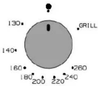
radar
| Category | Value | |---|---| | 130 | 130 | | 140 | 140 | | 160 | 160 | | 180 | 180 | | 200 | 200 | | 220 | 220 | | 240 | 240 | | GRILL | 260 |natural_image
Diagram showing a door with an open oven and a magnified inset illustrating the internal mechanism of a mechanical device (no text or symbols present)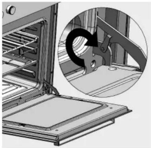
natural_image
Technical illustration of an oven with a magnified inset showing a mechanical component (no text or symbols)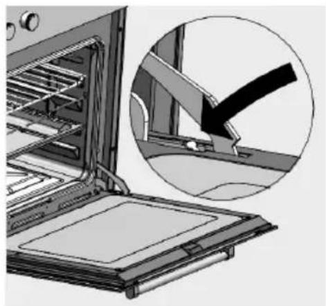
natural_image
Illustration of an oven with a magnified inset showing a mechanical component (no text or symbols)natural_image
Diagram showing a mechanical component with rotating arrows and labeled point A (no text or symbols beyond label)natural_image
Two schematic diagrams of a house with air purification and heating systems, showing internal components like fans, ovens, and steam (no text or labels)text_image
Technical diagram of an oven with labeled components A, showing internal structure and ventilation slotsALLACCIAMENTO ELETTRICO DEL FORNO
text_image
Technical diagram showing electrical connector layout with labeled components and dimensionsnatural_image
Mechanical assembly diagram showing pipe fittings and a valve (no text or symbols)text_image
Technical diagram of a mechanical assembly with labeled components A, B, and P, showing internal components and directional arrows.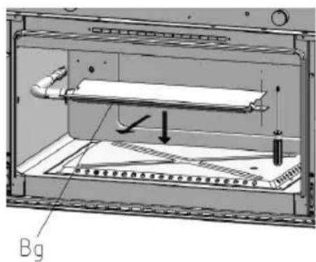
text_image
BgFINC90 - FI SC90
natural_image
Technical diagram of a mechanical assembly with labeled component I (no readable text or symbols)REGOLAZIONE DEL MINIMO DEL TERMOSTATO
natural_image
Diagram showing a mechanical device with a rotating shaft and a circular component, connected by an arrow (no text or symbols present)Taratura del minimo
natural_image
Diagram of a circular mechanical component with a central threaded part and a labeled point V (no text or symbols beyond the label)INSTALLATION, USE AND MAINTENANCE INSTRUCTIONS
MOD. FI60 - FI70 - FINC90 - FISC90 - FI TWIN
(GE) ELECTRIC GRILL
(GG) GAS GRILL
(GEV) VENTILATED ELECTRIC GRILL
(GGV) VENTILATED GAS GRILL
INDEX
USER GUIDE page
GENERAL RECOMMENDATIONS 3
USER GUIDE FOR OVEN 6
CONTROL PANEL 6
OVEN FUNCTIONS 7
INTERNAL GRILLS POSITION 9
USING THE GRILL 9
ELECTRIC GRILL 10
GRILL BURNER 10
OVEN BURNER 10
ELECTRONIC CLOCK OE 11
MECHANICAL TIMER CM 12
MAINTENANCE AND CLEANING 13
FUNCTIONING ANOMALIES 13
REMOVING THE OVEN DOOR 14
REPLACING THE OVEN LIGHT BULB 15
INSTALLATION INSTRUCTIONS 16
VENTILATION OF ROOMS USED 16
FEATURES OF THE CABINET 16
INSERTING THE OVEN INTO THE CABINET 17
OVEN ELECTRICAL CONNECTION 18
ASSEMBLY/REPLACEMENT OF THE POWER SUPPLY CABLE 19
EARTH CONNECTION 19
CONNECTION TO THE GAS MAINS 19
ADAPTATION TO THE DIFFERENT TYPES OF GAS 20
REGULATION OF THE THERMOSTAT MINIMUM 22
TECHNICAL AFTER-SALES ASSISTANCE AND SPARE PARTS 23
TECHNICAL DATA TABLES 24
GENERAL RECOMMENDATIONS
This product is in compliance with the EU 2002/96/EEC Directive.
The crossed out "wheeled bin" symbol on the appliance indicates that at the end of its life-span, the product, as it has to be separately treated from domestic waste, it must be conferred to a differential collection centre for electric and electronic appliances or redelivered to the dealer at the time of purchase of a new equivalent appliance.
The user is responsible for conferring the appliance at life-span end, in the appropriate collection structures, penalty sanctions envisioned by the legislation in force with regard to waste disposal.
The suitable differential collection for the subsequent start of the appliance dismissed to recycling, to treatment and to disposal compatible with the environment contributes to avoiding possible negative effects on the environment and on the health and safety and favours the recycling of the materials of which the product is made.
For more detailed information inherent the collection systems available, contact the local waste disposal service or the shop where the purchase was made.
The manufacturer declines all civil and liability liability in the case of bad or improper installation of the appliance.
The manufacturer also reserves the right to make modifications to his products that are deemed necessary and useful, without forewarning.
Do not dispose of the different packaging components but dispose of them in compliance with local Standards on this subject.
Before installation and use of this appliance this instruction manual must be read thoroughly in order to obtain all information necessary for correct installation, maintenance and use of the same.
It is very important that this instruction manual is kept with the appliance for its entire lifetime, even if transferred to other persons
This appliance has been designed for domestic use only for cooking and heating food.. Any other use, different to that indicated in this manual must be considered improper and consequently dangerous.
The product is in compliance with the 89/109/EEC European Directive as it is destined to come into contact with food products
This household appliance complies with the prescriptions of European Community LOW VOLTAGE DIRECTIVE – 2006/95/CE ELECTROMAGNETIC COMPATIBILITY DIRECTIVE 2004/108/CE REGARDING THE GAS 2009/142/CE
The product identification data is stated on the relevant plate applied to the internal face of the oven. The plate must never be removed
Installation must only be performed by qualified staff with respect for local Standards in force and following that indicated in this manual.
Important: do not lift or pull the oven by the hand.
In case of malfunctioning, disconnect the appliance from the electric mains (do not pull the power supply cable to disconnect the plug) and contact the authorised original spare parts technical after-sales centre. Close the gas system cock before any maintenance.
Never attempt to repair the appliance yourself.
Correct use of the oven
- The appliance must only be used by adults, keep children away
- The appliance produces heat both in the functioning phase and due to inertia, also when just switched-off. Do not touch parts inside the oven during these phases and limit the
contact with external parts. Keep children away from the appliance when operating, the accessible parts may become very hot - To insert or extract containers or accessories from the oven, always use suitable protective gloves
- Only use containers that resist high temperatures
- Do not leave the appliance unattended during cooking operations that may release greases or oils that may catch fire
- Never cover or lean on the walls or lower part of the oven, with sheets of aluminium or other objects such as pans or trays that could damage the product.
- Do not use the oven to store objects when it is not in use, in case they are forgotten inside and can cause damage, when the oven is switched-on, to oven itself or the objects
- Do not sit on or place weight on the open door and do not hang them on the handle, it could damage the product, creating malfunctioning
- Before maintenance or cleaning, disconnect the oven electrically and, if just used, wait for it to cool.
- Pay attention to the air flow that leaves the oven when the door is opened when the same is hot
- Do not use jets of steam for cleaning, which could reach and damage the electric parts
- If the connection cable should be damaged, contact the technical after-sales centre immediately, who will replace it
Attention, this appliance must be connected to earth in compliance with the standards in force. It can only be installed and function in places that are permanently ventilated according to relative local Standards in force. For installation of the oven see the “installation instructions” chapter
Conscious use of the oven
- Pre-heat the oven for the time strictly necessary
- Open the door only when necessary to prevent escape of heat
- Keep the gaskets clean and efficient to prevent damaging dispersions of heat
- Always switch the oven off when not in use
- To reduce the formation of condensate owing to the humidity contained in the foods, it is always necessary to pre-heat the oven before introducing the foodstuffs. In all cases any formation of condensate on the door glass or on the walls of the oven do not compromise its functioning and will tend to disappear with the cooking process.
Before using the oven for the first time:
Disconnect the appliance from the electric mains
Remove all internal packaging and accessories from the oven. Clean the internal surfaces with hot water or neutral detergent (see “maintenance and cleaning” paragraph) Rinse thoroughly with a damp cloth. Wash all oven accessories in the same way and dry everything thoroughly.
Recommendations:
- Do not store or use petrol or other inflammable substances in the vicinity of this article
- Never use this appliance to heat the environment
- Do not obstruct the passage of the burned gases and the cooling air blocking the ventilation holes of the room and ducts on the appliance. This creates anomalous functioning with possible increase of carbon dioxide to unsafe levels
- The use of a cooking appliance can lead to an increase in heat and humidity in the place where it is installed. Guarantee good airing of the kitchen and keep natural airing openings free and install a forced airing device (suction hood)
- The continuous use of the appliance can require extra ventilation, this can be solved by opening a window or increasing the suction hood power
- Before installation, check that the local supply conditions (nature and pressure of the gas) and the regulation state of the appliance are compatible
- The regulation conditions of this appliance are given on the label (or on the data plate)
- If there is an odour of gas in the room, open the window and wait for a complete change of air before re-igniting the burner
- This appliance is not connected to a combustion product evacuation device. This must be installed in compliance with the installation rules in force. Particular attention must be made to the applicable dispositions with regard to ventilation
- During use, do not touch the heating elements inside the oven
- The accessible parts can become very hot during use, it is opportune to keep children away.
In case of accidental switch-off during cooking, switch-off the gas burner by acting on the control knob (a safety valve intervenes anyhow, interrupting the gas flow). Try switching it on firstly opening the door completely. If gas is smelled in the room, open a window and wait for this to disappear before switching on the burner again.
USER GUIDE FOR OVEN
CONTROL PANEL
text_image
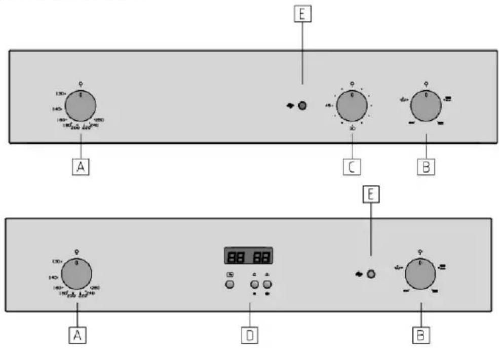
E 130+ 140- 150- 200- 250- 300- A C B E 130+ 140- 150- 160- 200- 250- 300- A D BA = Thermostat
B = Functions selector switch
C = Timer CM
D = Electronic Clock OE
E = Red power LED
The positions may vary depending on the model
Important:
Before using the oven for the first time, allow it to run empty and at maximum for about 1 hour. Air the room well, possibly opening a window. This will allow the evacuation of combustion fumes from production residues, which greases, oils and resin.
Power indicator LED (Red light)
When on, it indicates that the oven is live and on
Oven temperature thermostat:
The oven thermostat controls the temperature desired for cooking on all of the oven functioning selections.
Functions switch or selector
The switch activates the type of functioning desired for cooking.
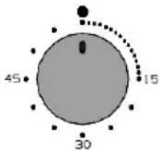
Mechanical timer CM (in the models set-up)
The mechanical timer can be used as a warning with acoustic signal at the end of the time period deemed necessary for cooking. Attention, cooking is not interrupted.
text_image
45 30 15CM
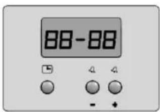
Electronic clock OE (in models set-up)
It allows the electronic display of the daily time and verification of the cooking time remaining with successive warning via acoustic signal. Attention, cooking is not interrupted.
text_image
88-88 4 4 - +OE
OVEN FUNCTIONS
(the symbols in the oven indicated for which functions it is set-up)

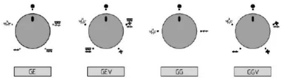
Oven light bulb (mod-GE;GEV;GG;GGV)
The oven light bulb can be switched-on independently at any time. The bulb stays on also with other functions.


Electric grill (mod-GE; GEV)
In this selection only the electric resistance on the upper part of the oven is functioning (the simultaneous use of the gas burner is not possible, a safety device prevents its functioning). The feature of the grill to emanate intense heat allows the use of the oven to grill and roast. For this type of cooking, the door must remain open. It is possible to use the spit in models where this function is set-up. Consult the “Use of the Grill” paragraph

Ventilated electric grill with spit (mod-GEV)
This function allows to grill in a softer manner thanks to the use of forced air. Depending on the models, it is possible to cook with the aid of the spit (if set-up). For this type of cooking it is necessary to keep the door open .Consult the “Use of the Grill” paragraph.

Only the fan is functioning without any heating element. This function can be used to defrost and/or dry the food to be cooked, only with the movement of air circulating at ambient temperature, or for a more homogenous and soft firing, using the oven burner. The oven fan cannot be activated during Gas Grill functioning. It is possible to use the spit in models where this function is also set-up.

Spit (mod-GE;GG;GEV;GGV)
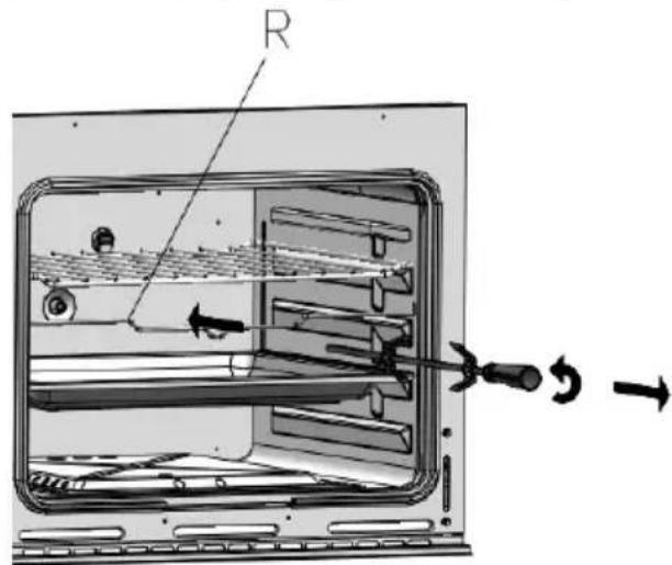
It is possible to use the spit in models where it is set-up. In models FISC90, the spit is positioned transversally with the connection on the back of the oven (in models FINC90, the connection is on the right wall of the oven) and its functioning is automatic in all functions, even if the symbol is not present. For use, act as follows. Place the dish well fixed with the appropriate fork hooks in the split rod and place everything inside the split stand frame, previously set-up in its slot on the drip pan. The spit grip made of insulating material must be used only to remove the spit rod from the oven and it must be removed during firing
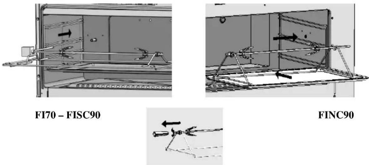
In models FI60 where set-up (not envisioned in versions GEV;GGV), the spit is positioned longitudinally and its connection is central in the oven's back. In this case also, insert the dish fixed with appropriate fork hooks of the split rod. Hook the split stand (R) to the side guides or in the appropriate slots (depending on the models). Do not leave the spit grip inside the oven during firing.
text_image
RFI60
It is recommended to insert foods into the oven when it has been pre-heated
INTERNAL GRILLS POSITION FOR SPECIFIC COOKING
Frozen cakes, Long roasts, Turkey, Cakes, Steak, Meat well done; position n. 1 and 2 from bottom.
Cakes, Sliced Bread, Toast, Casserole, Wholemeal bread, Meat; position n. 2 from bottom.
Biscuits, Thin cut meat; position n. 2 and 3 from bottom.
To Golden with Grill, use position n. 3 from bottom.
This data regarding the cooking positions are indicative and can be interpreted on the basis of your own experience.
USING THE GRILL
With the grill it is possible to cook fish, vegetables, small spits and various types of meat, with the exception of lean game meat. The meat cut in thin slices and fish must always be grilled quickly, slightly greasing them with oil using a suitable brush and placed always on the grill. The grill must be arranged in the position nearest to the upper heating element, in proportion to the thickness of the dish, in order to avoid externally burning it and not cooking it enough inside. Only salt the meat after cooking otherwise it will be less juicy. Never prick food during cooking, not even to turn it. Their juice would run making the grilled food dry.
To appreciate Grill cooking, it is necessary to pre-heat the oven for at least 10 minutes.
ELECTRIC GRILL
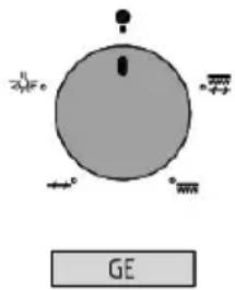
To optimise Grill cooking, pre-heat the switched on Grill oven (bring the selector knob in position (---) for at least 10 minutes. Introduce the dish inside the oven in the position closest to the Grill, depending on the type of food to cook Always use the Grill with the oven door open and for a maximum time of 15 minutes. When using this function, it is not possible to use the oven burner (a safety device prevents the insertion of the electric resistance if the thermostat knob is not in position
chemical
Simple diagram of a molecule with labeled atoms and directional arrows, including a label 'GE' below.GRILL BURNER
Fully open the oven door, a safety device prevents the switching on of the burners
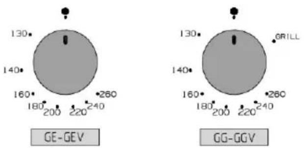
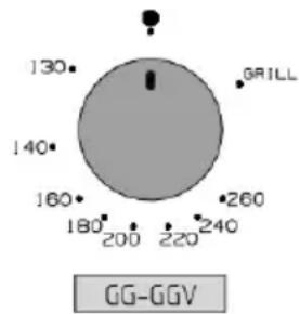
with the door closed, turn the thermostat knob clockwise to end run (GRILL position) and fully push it to trigger its ignition. After having switched on the Grill burner, keep the knob pressed for 3/5 seconds; this enables the thermocouple to heat up and therefore keep the safety valve open. Release the knob. For better results, we recommend pre-heating the oven for a few minutes. During use of this function it is not possible to use the oven burner.
text_image
130° 140° 160° 180° 200° 220° 240° 260° GRILL GG-GGVAt first use it is normal to have to repeatedly attempt switch-on due to the presence of air inside the gas ducts.
Meat can be arranged in suitable containers or cooked directly on the grill. In the latter case, always pour some water in the dripping pan then inserting it in the guides under the grill. In this way avoiding the grease dripping in the dripping pan burning creating bad odours.
Attention: during use of Grill, the accessible parts can overheat. It is therefore opportune to keep children at a due distance.
OVEN BURNER
Recommendation: thanks to the presence of a safety switch, the burner switch-on can be performed only with the door fully open.
Igniting the oven burner
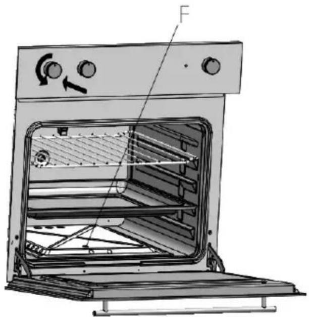
Completely open the oven door, slightly press on the thermostat knob and turn it anticlockwise, taking it to position 260^ . Fully press the knob to trigger the automatic switch-on of the oven burner. Ensure the flame is present on the burners verifying it through hole “F”. At first use it is normal to have to repeatedly attempt switch-on due to the presence of air inside the gas ducts
After having switched on the Grill burner, keep the knob pressed for 3/5 seconds; this enables the thermocouple to heat up and therefore keep the safety valve open and, therefore the burner switched on. Position the thermostat knob on the wanted temperature.
natural_image
Technical line drawing of an oven with internal structure and labeled component (F), no readable text or symbols present.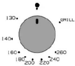
radar
| Category | Value | |---|---| | Point 1 | 130 | | Point 2 | 140 | | Point 3 | 160 | | Point 4 | 180 | | Point 5 | 200 | | Point 6 | 220 | | Point 7 | 240 | | Point 8 | 260 | GRILL label is positioned near the top of the circle.To facilitate identifying the position of minimum, the thermostat has a stop in that position.
To switch-off the burner from the position of minimum just press the knob slightly and
turn it to position
While using the oven burner the Grill burner cannot be activated.
The burner is equipped with a safety valve that locks the gas supply in case the flame accidentally goes off.
The oven should never be used to heat the home or room in which it is installed.
A prolonged and intensive use of the appliance may require additional ventilation by means of opening a window or increase the forced suction power (electric blower).
ELECTRONIC CLOCK OE (in models set-up)
The electronic clock, as well as displaying the current time, can also be useful as timer
to warn when the cooking time has terminated. Attention,
cooking is not interrupted by the electronic clock but it is necessary to act on the manual oven controls
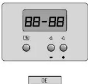
After having connected the household appliance to the electric mains and, in case of temporary interruption of the electric current supply, the display of the electronic clock will start to flash.
text_image
88-88 DESetting the time
Press the button, set the time by acting on the + and --. buttons.
This function remains active for 7 seconds after the last action on the + or -- buttons. To modify the time set, press the □ button for 4 seconds until the characters of the hour start to flash. Amend the time by pressing the buttons + or -- Press the button □ once again and adjust the minutes by acting on the + or -- buttons again.
Timer
Use the electronic timer as a warning with acoustic signal at the end of the time period necessary for cooking. Attention, cooking is not interrupted.
Setting the timer
Press button ≠ once, press the same button again to increase the duration time. The
setting unit is of 10 seconds per impulse. For quick scrolling, keep the key + pressed. Countdown has priority on the display.
The maximum time is 10 hours. After having reached 99 minutes and 50 seconds, the time setting changes in 1h and 40 min. The bell symbol indicates that the timer is activated.
To see the time during countdown, press button ☐. The time will appear for 6 seconds, after which countdown is displayed again.
Resetting the timer
Press and hold the -- button down until the previously set time has been reset Acoustic signal
Once the set alarm time has been reached, the acoustic signal will ring for 7 minutes. To interrupt the acoustic signal, press one of the three buttons indifferently.....
It is possible to set the frequency of the acoustic signal by choosing from three different
levels by pressing the button -- . Resetting the timer does not interrupt cooking.
MECHANICAL TIMER CM (in the models set-up)
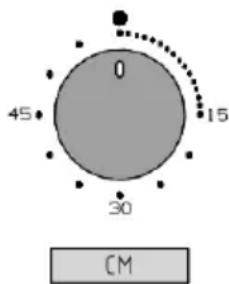
The mechanical timer can be used as a warning with acoustic signal at the end of the time period necessary for cooking. To select the desired time, turn the knob to the corresponding time in minutes.
When this time has passed, the timer will emit an acoustic signal.
Resetting the timer does not interrupt cooking.
text_image
0 15 45 30 CMTangential fan (models set-up)
In the set-up models, a tangential fan is provided for the cooling of the controls panel and of the oven door's handle. This fan starts to function a few minutes after the start of cooking, when the oven reaches a certain temperature (the time varies according to the model) and also prevents overheating of the housing cabinet. The hot air expelled from below the control panel will continue to escape also after the oven has been switched-off, until the temperature does not fall to normal levels.
MAINTENANCE AND CLEANING
Disconnect the electric power supply before performing any type of maintenance on the product
Do not use system cleaners on the appliance.
Do not use coarse, abrasive or sharp metal scrapers to clean the oven door, as they can scratch or damage the surfaces, do not use acid products (like anti-scaling agents) as they can damage the enamelled parts.
Switch-off the burners and heating elements, wait for the internal parts of the oven to cool down before touching or cleaning them. Pay great attention to the cooking grills. Clean the oven with care. Be careful to avoid scalding from steam in case a wet sponge or cloth, used for cleaning residues, comes into contact with a hot surface. Moreover, some dettersives create noxious fumes on contact with the heat.
Periodic maintenance
Periodical check the state of the rubber gasket located around the oven opening. This guarantees the correct functioning of the oven. Clean this gasket avoiding the use of abrasive objects or substances. If gasket damage is noted, contact the nearest technical after-sales centre.
The gas thermostat requires periodical lubrication, which must only be performed by qualified staff.
Cleaning the surfaces
The enamelled or stainless steel parts must be treated with caution. Use water or specific products, accurately drying with a soft cloth. Do not use abrasive products. In case of difficult encrustation on the enamelled parts, use a plastic sponge or similar, soaked with hot water and vinegar. If food residues or oil, sugar, grease stains, etc., are not immediately removed after having terminated using the oven, they can become more difficult to remove. It is recommended to clean internal parts of the oven when it is still warm, the task will be easier.
Due to an increasing presence of new products on the market, it is impossible to establish a list of items useful for cleaning this appliance. Read the manufacturer's instructions thoroughly to check the possible use of detergent.
FUNCTIONING ANOMALIES
In the event of anomalous functioning, contact the nearest qualified and authorised technical after-sales centre immediately.
The verifying of any of the situations listed below, is to be considered functioning anomaly and, consequently, require the intervention of a technician:
- Flames with yellow tips.
- Difficulty igniting the burner.
- Burner that does not remain on.
- Burner switch-off without reason
- Difficulty in turning the cock-thermostat.
Regularly check the correct functioning of the cocks-thermostats and of the switches.
REMOVING THE OVEN DOOR
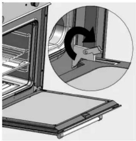
To remove and reinsert the oven door, follow the instructions given below. Open the oven door completely. Lift the hinge hook and insert it inside the locking support on both hinges. see figure. This blocks the hinge in the open position. Grip the bottom sides of the door with both hands. Lift the door by a few centimetres (there will be a resistance of the spring caused by the locking of the hinge). When the door is sufficiently lifted, the hinges can be extracted from their seats. Pull the door towards yourself to release the hinges from the openings of the oven frame.
natural_image
Diagram showing a door opening with an inset circular view of a mechanical component (no text or symbols)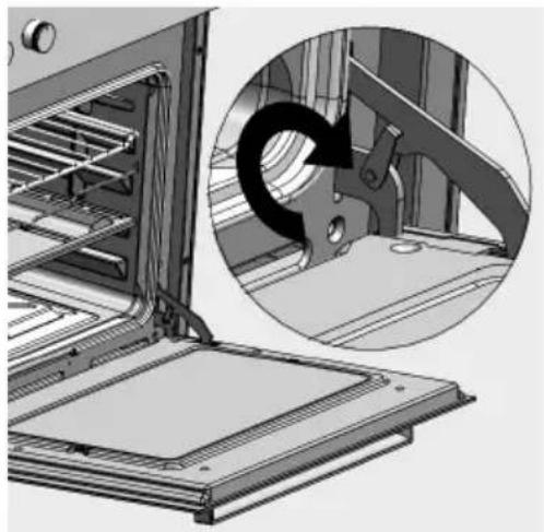
natural_image
Technical illustration of an oven with a magnified inset showing internal components (no text or symbols)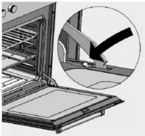
natural_image
Illustration of an oven with a magnified inset showing a mechanical component (no text or symbols)Re-insertion of the oven door
Act in reverse order, holding the door sideways with both hands towards the bottom and inserting the hinges in the openings of the front oven frame, (pay attention to the positioning of the foot joint). With the oven door fully opened, remove the hinge lock bringing the locking hooks in their original position. Close the oven door slowly and make sure that it has been correctly inserted and aligned with the lateral edges.
Attention- Do not remove the hinge locking hooks from their seat when the door is not mounted in the oven. Do not close the hinges without the weight of the door as it causes a violent closing of the springs.
Do not rest weights on the door or hang them on the handle, they could damage the products, creating malfunctions
Moreover, do not use the oven until the oven door has been re-mounted correctly.
REPLACING THE OVEN LIGHT BULB
To prevent electric shocks and/or damage to persons, read and follow the procedure given below:
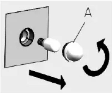
natural_image
Diagram showing a wall-mounted bulb connected to a circular component with a curved arrow indicating rotation (no text or symbols)Before replacing the oven light bulb, make sure that the electric current has been removed by opening the master switch.
Ensure that the oven and the light bulb are cold, then remove the protection cover A.
Do not touch the hot bulb with damp cloth, breakage may be caused.
Replace the light bulb with another suitable one of 25 W
for 220 - 230 V with attachment type E14 suitable for high temperatures.
In case the protection cover is damaged or broken, do not use the oven until the cover has been replaced or re-inserted correctly and safely.
Attention: for correct installation and use of this appliance, refer to the technical data given on the serial label of the product.
The product label is on the edge of the internal side of the oven. A second label is found on the cover of the instruction book.
INSTALLATION INSTRUCTIONS
The installation and technical assistance must only be performed by qualified staff. Read the safety instructions given in this manual thoroughly before using the oven. Incorrect installation, regulation, calibration, maintenance, assistance and use can cause serious damage/injury to persons or objects
This product must be installed a envisioned by this manual in compliance with National Standards and local regulations in force.
VENTILATION OF ROOMS USED
This household appliance must be installed and only function in permanently ventilated rooms and have greater ventilation when requested by relative local Standards in force. Such ventilation must guarantee a correct exchange of combustion gases, of air circulation and must maintain the work temperature within the safety limits.
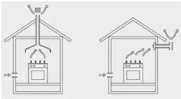
natural_image
Two schematic diagrams of a house interior with air purification and heating systems (no text or labels)The flow of air in the room must take place directly through the openings made in the external walls. These openings must have a free passage section of at least 100 cm^2 such that it cannot be accidentally obstructed.
The combustion products discharge must happen through suction hoods connected to flues or directly to the outside.
In case it is not possible to install the suction hood, an electric blower must be applied to the external wall or to the window of the room of use, as long as there are air inlets in the room envisioned by the Standards in force and proportioned for the capacity of the electric blower. The fumes discharge systems must be functioning during use of the appliance
Do not lift or pull the oven from the door handle and do not put pressure or load weights when this is open
Installation is the responsibility of the purchaser and any interventions requested of the manufacturing company due to an incorrect installation will not be included in the warranty
FEATURES OF THE CABINET
The cabinet has the following requisites;
- The cabinet and its components must be able to resist a temperature of 90^ C without deformations and/or defects of the surface.
- The cabinet must allow the free passage of the oven connections.
- All kitchen cabinets at household level must be protected with fireproof material according to the Standards in force.
INSERTING THE OVEN INTO THE CABINET
It is important that all operations relating to the installation of the appliance are carried out by qualified staff. The oven can be installed both in tall unit and under the work top of a kitchen cabinet.
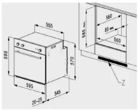
text_image
555 570 595 595 20-25 545 585 mm 560 80 mm 560 Zfig.01 FI60
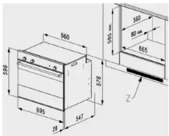
text_image
660 596 695 28 547 576 585 mm. 560 80 mm 665 Zfig.02 FI70
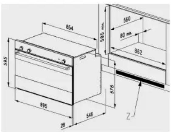
text_image
854 595 895 28 546 576 585 mm. 560 80 mm. 862 Zfis.03 FINC90/SC90
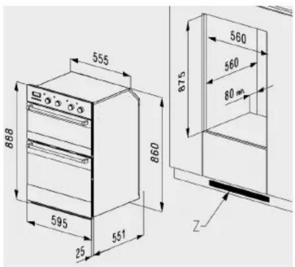
text_image
555 888 595 25 551 860 560 875 560 80 mm Zfig.04 FI TWIN
Built-in measurements
The dimensions of the opening to be made on the cabinet for fitting the oven are indicated in figures. Ensure that the cabinet where the oven is to be installed, is able to support the weight of 30 kg for FI 60; 45 kg. for FI 90 and FI 70; 70 kg for FI TWIN. For the opening in the cabinet follow the respective dimensions of the type of oven purchased, indicated in Fig. 01 for FI 60, Fig. 02 for FI 70, Fig. 03 for FI 90 and Fig. 04 for FI TWIN.
It is necessary to create an opening in the rear part of the bottom of the cabinet or in the oven support shelf, (see figures), to allow sufficient air to circulate for the cooling of the oven during functioning. For a good functioning of the gas burners, as well as the rear opening, a further opening must be made on the kitchen skirting board. The lacking of this opening can cause the malfunctioning or switch-off of the gas burner
Ensure the oven is safely installed inside the cabinet. Use screws A for fixing the oven.
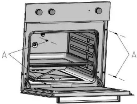
text_image
Technical diagram of an oven with labeled components and directional arrows indicating parts AMake sure that the electric current has been removed before connecting the oven to the electric mains.
Functioning happens in single-phase alternate current 220-230-240 V\~ 50-60 Hz, using flexible cable. Ensure that the household system can support the charge of the appliance. (see serial plate).
The electric safety of this appliance is only assured if the same is correctly connected to a system having efficient earth connection, according to the legal Standards in force.
In case of permanent connection to the electric mains, apply a bipolar switch dimensioned to the corresponding charge, with an opening for every contact of at least 3 mm.
In models where present, the flexible cable is supplied without plug. The plug to be used must be suitable to the electric charge of the product and must comply with the Standards in force.
The installer must ascertain that the section of the socket cables is suitable to the power absorbed by the oven, as indicated in the serial plate.
The connection socket must be easily accessible.
ASSEMBLY/REPLACEMENT OF THE POWER SUPPLY CABLE
The electric cable must be kept locked to the terminal box by the cable fix, so that it cannot come out. Connect the line cable to clamp L, the neutral cable to clamp N and the yellow/green cable to the earth clamp 12 . The yellow/green cable must be longer than the other by at least 20 mm.
Be careful that the electric cable does not pass near or comes into contact with the surfaces that reach temperatures above 75^ C.
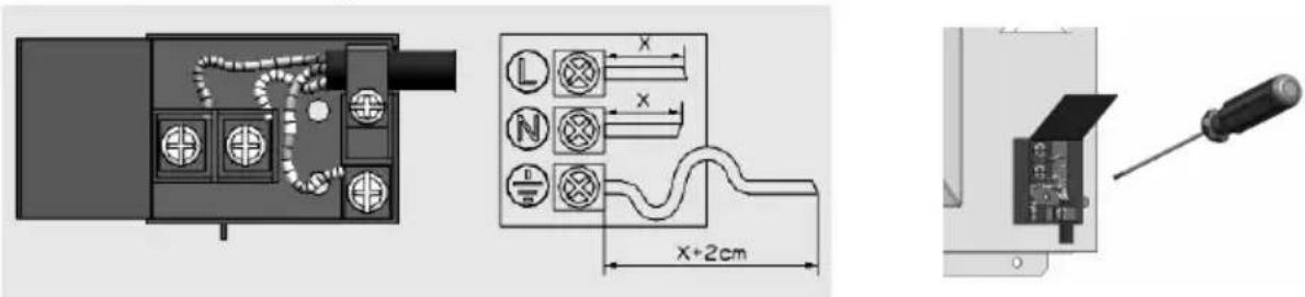
text_image
Technical diagram showing electrical connector layout with labeled components and dimensionsEARTH CONNECTION
Installation, connection and earthing of the electric system must comply with the European standard requisites and, however, fall within the parameters of the local Standards in force.
This household appliance requires an earthing connection for your protection from any short-circuits or electric dispersions. It must therefore be connected to a suitable electric socket. The earth cable must not be interrupted by the switch.
ATTENTION:
DISCONNECT THE ELECTRIC POWER SUPPLY BEFORE PERFORMING TECHNICAL ASSISTANCE OR MAINTENANCE ON THE PRODUCT.
In case of replacement of the electric cable, ensure the use of an electric cable certified according to the Standards in force and suitable to the technical features of the product.
Use only flexible cables:
for oven GGV or GGVT cable type H05RR-FH 3 x 0.75
for oven GET or GEVT cable type H05RR-FH 3 x 1.5
CONNECTION TO THE GAS MAINS
This household appliance must be installed and functioning only in permanently ventilated rooms according to relative local Standards in force.
Gas compatibility
Before installing, verify that the local distribution conditions (gas type and pressure) and the adjustment state of the appliance, are compatible (see the appliance technical data plate). If not, before continuing, read the indications of the paragraph “adaptation to the different types of gas”.
Connection to the gas mains
Connection to the gas mains must be carried out in compliance with the relative local Standards in force and only by a trained technician or qualified installer of gas appliances that must also carry out the seal test, carefully following the outline below.
For the connection, follow the control list below:
a) switch-off all pilot flames off and close the respective valves of other gas appliances present
b) close the main valve of the home's gas network
c) interpose a ball valve between the gas mains and the oven, in an easily accessible position
d) connect the appliance to the gas network using a flexible stainless steel pipe, limited to those with maximum extension of 2 mt., or a rigid copper pipe with suitable dimensions (the use of the rubber flexible pipe is forbidden as it cannot be inspected) ensure the flexible metal pipe does not come into contact with mobile parts or is crushed. Ensure that the ramp connection pipe of the oven and the various fittings are not obstructed by dirt, foreign objects, etc. If these parts are left inside the ramp pipe they can damage the oven faucets
e) now proceed with the connection of the oven to the gas mains paying attention to the assembly of the various fittings and relative gaskets G
f) open the main valve of the gas mains again. Apply a soapy water solution on the joints of the new gas connections to check the seal.
g) open the ball valve upstream of the gas appliance and, in case of air bubbles, slightly tighten the connection component until the leak has stopped or, check it has been correctly fastened. Repeat the seal test
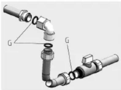
text_image
Technical diagram of a pipe fitting with labeled components G, showing assembly and assembly detailsImportant: never use naked flame to check for gas leaks. After the seal test, clean the surface from any residue substances.
It is now possible to switch-on the pilot flames of the other gas appliances.
In case of having to install a cooking top combined with a gas oven, the connection to the gas mains cannot happen through only one shut-off ball valve. The two products must be connected separately using two independent ball valves
ADAPTATION TO THE DIFFERENT TYPES OF GAS
All oven models are accessorised with exchange injectors kit for the LPG and/or Neutral gas. Check the product label to verify the type of production calibration gas. To replace the injectors and to adjust the minimum capacity, read the paragraph “replacement of the injectors”
The oven burner does not require adjustment of the primary air
Replacement of the injectors
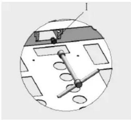
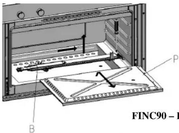
Firstly, electrically disconnect the oven and close the ball valve supplying the gas. To replace the injectors, remove the screw fixing the burner to the front part (for the oven burner it is firstly necessary to extract the removable top P) Slightly and cautiously extract the burner B from the rear seat, being careful not to shake the thermocouple and the ignition spark plug cable.
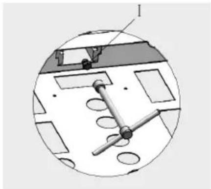
Subsequently, using a 7 mm hexagonal spanner, loosen the injector I and replace it following the indications in the table “gas burners technical data”. Re-mount the burner following the above described operations, but in reverse order. Now follow the instructions in the paragraph “regulation of the thermostat minimum”
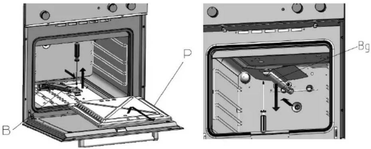
text_image
P B BgFI60 - FI70
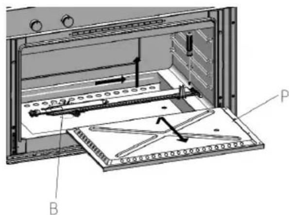
text_image
Technical diagram of a mechanical assembly with labeled components A, B, and P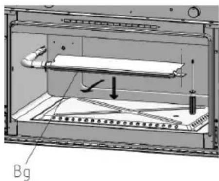
text_image
BgFINC90 - FI
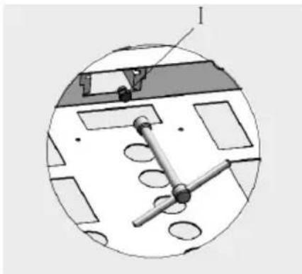
natural_image
Technical diagram of a mechanical assembly with labeled component I (no text or symbols present)REGULATION OF THE THERMOSTAT MINIMUM
Perform this operation with the oven already inserted in the cabinet and with the electric and gas connections already carried out, as from previous instructions
It is necessary to perform the adjustment of the minimum every time the type of gas is changed, in order to guarantee the good functioning of the burners
In minimum position, the flame must be stable and must not go off when passing from maximum to minimum, and vice-versa. The height of the flame in minimum position must be of about 5 mm.
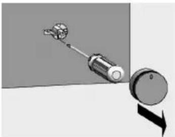
natural_image
Mechanical assembly diagram showing a screwdriver interacting with a circular component (no text or symbols)Calibration of the minimum
Ignite the burner to be calibrated and make it function for a few minutes. Bring the knob
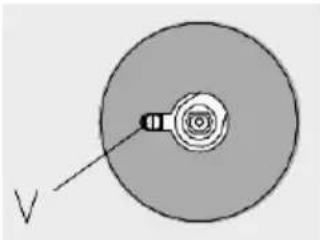
index to minimum position, remove the knob. Introduce a small Phillips screwdriver in the opening on the left side of the thermostat shaft, optimise the height of the flame by closing or opening the adjustment screw V with the shaft locked. Carry out a few normal closing and opening tests of the door and, in case of switch-off, slightly lift the minimum.
natural_image
Simple diagram of a circular component with a central threaded section and an arrow labeled 'V' pointing to it (no text or symbols beyond the label)NOTE: All adjustments must be realised only by qualified and authorised staff. To guarantee a correct and safe operation, the oven must be suitably installed and connected to earth/mass by qualified and authorised staff. Ask the installer to show you the position of the connection ball valve to the gas mains and how to close it in case of need. Disconnect the appliance from the electric mains before any intervention.
TECHNICAL AFTER-SALES ASSISTANCE AND SPARE PARTS
Spare parts
Only authorised components can be used for the household appliance assistance. Do not repair or replace any oven component that has not been recommended in this manual. All interventions and repairs must be carried out by authorised technical staff.
To request a spare part, indicate the following data:
1) Oven model initial (MOD.) and production number (N.L.), found on the product label positioned on the lower front part of the oven facade and in the first page of the booklet.
2) Description and number of the spare part, technical information available only to the authorised assistance service.
3) Lastly, indicate the data of the distributor that sold you the oven and the data of the nearest assistance centre to you.
Technical assistance
In case your oven requires technical assistance and/or spare parts, contact the dealer or the authorised technical assistance centre nearest to you.
In this case also it is necessary to transmit the full appliance data found on the aluminium product label, which: model (MOD.) lot number (N.L.), etc, label placed on the lower part of the oven facade or on the first page of the instructions booklet
TECHNICAL DATA TABLES
| GAS BURNERS TECHNICAL DATA | |||||||||
| Mod Bruc. Power kW | Gas Pressure (mbar) | Injectors (mm) | By-pass (mm) | ||||||
| Nat. G20 | But-Prop G30/31 | Nat. G20 | But-Prop G30/31 | Nat. G20 | But-Prop G30-31 | ||||
| FI60 | oven 2,20 | 20 30/37 1,10 | 0,70 reg. | 0,40 | |||||
| grill | 2,10 20 30/37 | 1,10 0,72 - - | |||||||
| FI70 | oven 2,20 | 20 30/37 1,10 | 0,70 reg | 0,40 | |||||
| grill | 2,70 20 30/37 | 1,20 0,80 - - | |||||||
| FINC90 | oven 3,30 | 20 30/37 1,30 | 0,85 reg. | 0,52 | |||||
| grill | 3,20 20 30/37 | 1,30 0,85 - - | |||||||
| FISC90 | oven 3,30 | 20 30/37 1,30 | 0,85 reg. | 0,52 | |||||
| grill | 3,20 20 30/37 | 1,30 0,85 - - | |||||||
| FI TWIN | oven 2,20 | 20 30/37 1,10 | 0,70 reg. | 0,40 | |||||
| / | |||||||||
| EXTERNAL DIMENSIONS | |||||||||
| model | width (cm) | height (cm) | depth (cm) | ||||||
| FI60 | 59,5 | 59,5 | 55 | ||||||
| FI70 | 69,5 | 59,5 | 55 | ||||||
| FINC90 | 89,5 | 59,5 | 55 | ||||||
| FI SC90 | 89,5 | 59,5 | 55 | ||||||
| FI TWIN | 59,5 | 88,8 | 55 | ||||||
| FUNCTIONING TECHNICAL DATA | |||||||||
| model | FI60 | FI70 | FINC90 | FISC90 | FI TWIN | ||||
| F60 | F30 | ||||||||
| voltage | 220/230/240V - 50/60Hz | ||||||||
| total electric power | 2,2 kW | 2,2 kW | 1,8 kW | 2,6 kW | 2,6 kW | 1,8 kW | |||
| electric grill resistance | 1,8 kW | 1,8 kW | 1,8 kW | 2,5 kW | 2,6 kW | 1,8 kW | |||
| circular heat | / | / | / | / | / | 1,5 kW | |||
| oven light bulb | 25 W | 25 W | 25 W | 25 W | 25 W | 25 W | |||
| oven fan | 25 W | 25 W | 25 W | 25 W | 25 W | 25 W | |||
| tangential fan | 25 W | 25 W | 25 W | 25 W | 25 W | 25 W | |||
| spit motor | 1-5 W | 1-5 W | 1-5 W | 1-5 W | / | / | |||
| INTERNAL DIMENSIONS | |||||||||
| model | FI60 | FI70 | FINC90 | FISC90 | FI TWIN | ||||
| F60 | F30 | ||||||||
| useful volume | 56 lt. 77 lt. | 71 lt. | 110 lt. | 56 lt 31 lt | |||||
| grill cooking area | 726 cm2 | 726 cm2 | 1000 cm2 | 1200 cm2 | 726 cm2 | 726 cm2 | |||
| ENERGY CONSUMPTION | |||||||||
| model | FI60 | FI70 | FINC90 | FISC90 | FI TWIN | ||||
| F60 | F30 | ||||||||
| G20 natural gas | 210 l/h | 210 l/h | 315 l/h | 315 l/h | 210 l/h | / | |||
| LPG G30 | 160 g/h | 160 g/h | 240 g/h | 240 g/h | 160 g/h | / | |||
| OVEN ACCESSORIES | |||||||||
| model | FI60 | FI70 | FINC90 | FISC90 | FITWIN | ||||
| F60 F30 | |||||||||
| oven dripping pan | yes yes | yes | yes | yes yes | |||||
| internal grills | yes yes | yes | yes | yes yes | |||||
natural_image
Mechanical component diagram showing a lever and dial with motion arrow (no text or symbols)natural_image
Diagram of a circular object with a central spiral and labeled point V, no text or symbols present.معايرة الحد الأدنى
text_image
Technical diagram of an oven with labeled parts B and P, showing internal components and assembly lines.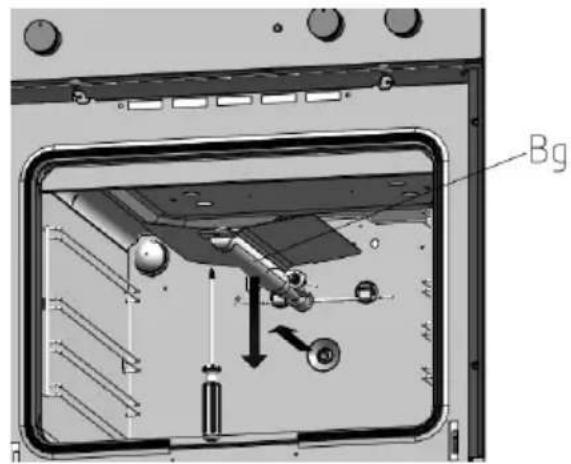
text_image
BgFI60 - FI70
text_image
FINC90 - I A B P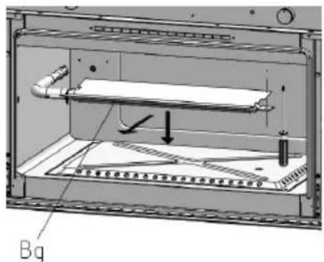
text_image
BgFINC90 - FI SC90
natural_image
Technical diagram of a mechanical device with labeled component I, showing internal components and mounting holes (no text or symbols beyond label)natural_image
Exploded view diagram of a pipe fitting with labeled components (no text or symbols present)text_image
Technical diagram showing a mechanical component with labeled parts and a schematic of a wiring or connection setup with dimensions.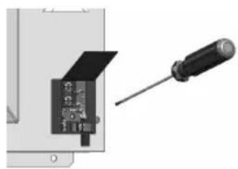
natural_image
Close-up of a screwdriver inserted into a device component (no visible text or symbols)التوصيل بالأرض
text_image
Technical diagram of an oven with labeled components and directional arrows indicating parts Anatural_image
Two schematic diagrams of a house interior showing internal components and airflow paths (no text or labels)natural_image
Diagram showing a wall socket connected to a bulb with a rotating arrow indicating rotation (no text or symbols)natural_image
Diagram showing a door frame opening with an inset circular view of a mechanical component being turned into a cabin (no text or symbols present)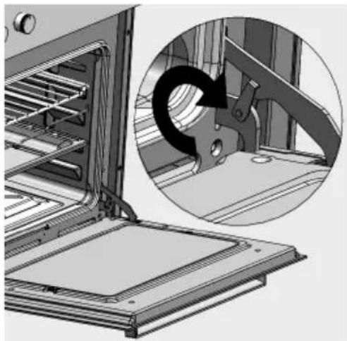
natural_image
Technical illustration of an oven with a magnified inset showing a mechanical component (no text or symbols)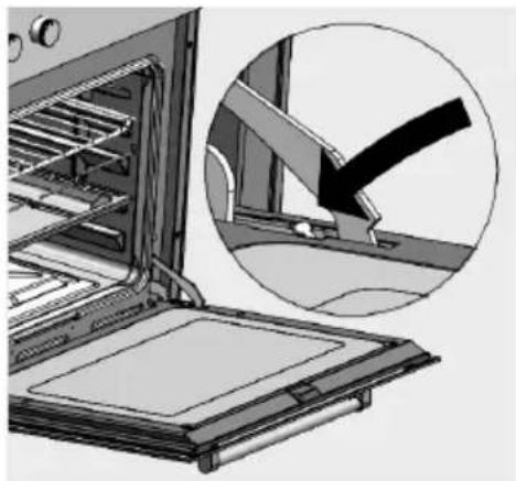
natural_image
Illustration of an oven with a magnified inset showing a mechanical component (no text or symbols)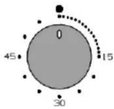
text_image
0 15 45 30CM
text_image
88-88 + -OE
natural_image
Technical line drawing of an oven with internal compartments and control knobs (no text or symbols)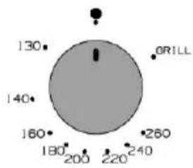
radar
| Angle | Value | |---|---| | 0° | 130 | | 90° | 140 | | 180° | 160 | | 270° | 180 | | 360° | 200 | | 450° | 220 | | 540° | 240 | | 630° | 260 | ORILLAR
natural_image
Technical diagram of a mechanical assembly with internal components and directional arrows (no text or symbols)FI70 - FISC90

natural_image
Technical diagram of a mechanical assembly with no visible text or symbols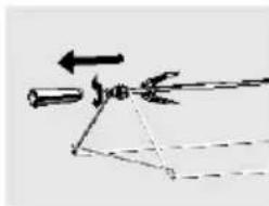
natural_image
Pure mechanical diagram showing a lever and pivot point without any text or symbolsFINC90
AR
text_image
88-88 4 4 - +OE