
ADN 102 - Ice Maker WHIRLPOOL - Free user manual and instructions
Find the device manual for free ADN 102 WHIRLPOOL in PDF.


User questions about ADN 102 WHIRLPOOL
0 question about this device. Answer the ones you know or ask your own.
Ask a new question about this device
Download the instructions for your Ice Maker in PDF format for free! Find your manual ADN 102 - WHIRLPOOL and take your electronic device back in hand. On this page are published all the documents necessary for the use of your device. ADN 102 by WHIRLPOOL.
USER MANUAL ADN 102 WHIRLPOOL
Operating Principle....4
Specifications
Installation diagrams for inlet/outlet tubes and dimensions 8
Consumption data, weights, crated dimensions and volumes 8
Technical data....8
Model IQ 135 + S60 "Compact" 8
Model IQ 150/200/400/550 9
Model IQ 1100....10
Rating plate and serial number 14
Installation
Recommended placement of unit 15
Water and drainage.... 15
Connecting unit to water source (water-cooled units) 16
Connecting unit to drain.... 16
Electrical connections.... 16
Assembling the dispersion cone 16
Operation
Preliminary checks 17
Starting up.... 17
Inspection and adjustment of water level in the trough 18
Cross check 18
Adjustments
Expansion valve 18
Water level 19
Pressure-controlled valve on cooling water circuit 20
Fan pressostat (air-cooled models).... 20
High pressure safety pressostat.... 21
Start-up timer 21
Safety elements 21
Inspection/replacement procedures
Lower bearing 22
Speed reducer (gearbox) 22
Upper flange 23
Upper bearing (depending on model).... 24
Maintenance and cleaning instructions
Maintenance table 25
Water condenser 26
Air condenser 26
Evaporator/ water trough....
26
Cleaning the water inlet filters....
27
Checking for water leaks....
27
Ice Queen 550. Installation instructions28
INTRODUCTION
Thank you for choosing ITV's ICE QUEEN flaker.
You have purchased one of the most reliable ice-making products on the market today. Carefully read the instructions contained in this manual since they provide important information relative to safety during installation, use, and maintenance.
WARNINGS
This appliance should be installed by approved Technical Service Personnel.
This plug should be accessible at all times.
To reduce the risk of electrical shock, ALWAYS disconnect the machine BEFORE cleaning or maintaining the equipment. Do not attempt to install, service, or modify this machine. Improper use by other than specially trained technicians is extremely dangerous and may result in a fire or electric shock.
This machine should not be placed outdoors or exposed to rain.
Connect to drinking water mains.
This appliance is not intended for use by young children or infirm persons without supervision.
Young children should be supervised to ensure that they do not play with the appliance.
IMPORTANT!
- DO NOT ATTEMPT TO SERVICE THIS MACHINE AS IT IS DANGEROUS AND COULD CAUSE SEVERE DAMAGE TO THE UNIT.
- SERVICE SHOULD ONLY BE CARRIED OUT BY TRAINED, QUALIFIED PERSONNEL.
- WE STRONGLY RECOMMEND USING ONLY ORIGINAL REPLACEMENT PARTS AVAILABLE FROM AN AUTHORIZED DISTRIBUTOR.
- WASTE AND OTHER MATERIAL SHOULD BE DISPOSED OF ACCORDING TO LOCAL REGULATIONS AND PROCEDURES FOR WASTE DISPOSAL.
- CLEANING AND MAINTENANCE ARE NOT COVERED BY THE WARRANTY.
DESCRIPTION
Main Features of the Machine
β 18/8 stainless steel housing
β Powerful speed reducer (24Kg./m. @ 7 rpm.)
β Copper evaporator on precision bored tubing (HB 50)
β Durable stainless steel auger with resilient coating
β Ice drops out of the bottom of unit
β Speed reducer in top part of the unit
β Ecological refrigerant R404a
OPERATING PRINCIPLE
Water enters water trough via a float valve which provides a constant head of water. Through a hole in the bottom of the trough, water flows into the bottom of the evaporator and floods it to the same height as in the water trough. Water freezes upon contact with evaporator wall, and is scraped off as ice by the vertical, rotating auger. Ice is carried upward until it passes through discharge flap and falls into bin. When bin is full, automatic shut-off sensor (micro-switch on discharge flap) switches off machine.
IMPORTANT!
If unit is placed on top of a cold room, and/or ice has to fall a long distance from unit, a MECHANICAL ICE LEVEL SENSOR should be installed. To prevent ice from compressing in cold storage, we recommend transferring ice through a plastic tube (80-100 mm diameter) attached to its lower end the DISPERSION CONE which is PROVIDED WITH THE MACHINE in all models.

c_2 -Contact (Compressor)
c_3 -Feedback contact
Dis. -Circuit Breaker (motorgear)
Pv. -Fan pressostat (only air cooled models)
V. -Fan
S. -Compressor
Ip. -On/off switch
St. -Full storage bin stop
lw. -Water low level float switch
Ps. -High pressure safety pressostat
R. -Gearmotor
L. -Electrical interference filter (capacitor)
Pt. -Motor thermal protection
18/10/04 plano:24/10
-Detector de fase/Phase sequence relay
Ca ^1 - Contacto auxiliar motorreductor/Auxiliar contact gearmotor
Ca? -Contacto auxiliar autoalimentacion/Auxiliar lb. -Interruptor horario / clock switch
1 -Termico compressor/Thermic compressor
-Termico Motorreductor/Thermic gearmotor
-Verde linea / Green on -Ambar, llacado / Yellow full
V -Fase cambia/Phase sequence
| REGULACION TERMICOS OVERLOAD SETTING | |
| COMPRESOR | 3.6 A |
| MOTORREDUCTOR | 1.3 A |
18-10-04
text_image
515 550 5 0 0 Ice discharge slot Water trough overflow 869 73 15 207 80 50 82 100 869 869 1 3 6 9 Rating Plate Serial number Cooling water drain (water-cooled models) Electrical connection Water inlet Height increases by 80 mm when feet are fitted 62 55 Ice bin drain| MODEL | ICE BIN STORAGE CAPACITY (KG) | COOLING WATER CONSUMPTION (L/Hour) | WATER CONSUMPTION (L/Hour) | NET WEIGHT (KG) | DIMENSIONS (CRATED) X*Y*Z | GROSS WEIGHT (KG) | VOLUME (M3) |
| IQ 135 A | 60 | 5.5 | 70 | 615x650x1465 | 85 0.58 | ||
| IQ 135 W | 60 | 40 | 5.5 | 68 | 615x650x1465 | 83 0.58 |
| MODEL | REFRIGERANT CHARGE(gr) | HIGH PRESSURE | LOW PRESSURE AVERAGE | TOTAL AMPS(2)(A) | FUSE RATING(A) | COMPRESSOR POWER(1)(W) | TOTAL POWER(2)(W) | ||||
| MINIMUM | MAXIMUM | ||||||||||
| Kg/cm_2 | Psi | Kg/cm_2 | Psi | Kg/cm_2 | Psi | ||||||
| IQ 135 A | 500 | 16 | 228 | 17 | 242 | 2.5 | 35 | 4.2 | 16 | 360 | 650 |
| IQ 135 W | 360 | 16 | 228 | 17 | 242 | 2.5 | 35 | 4.2 | 16 | 360 | 650 |
(1) Data obtained at room temperature 20°C, water introduced at 15°C; water quality = 500ppm
(2) Maximum consumption obtained at room temperature = 43°C, according to UNE climate classification, Class T (TROPICALISED).
NOTE: Expansion controlled by capillary.
Model: ICE QUEEN 150 / 200 / 400 / 550
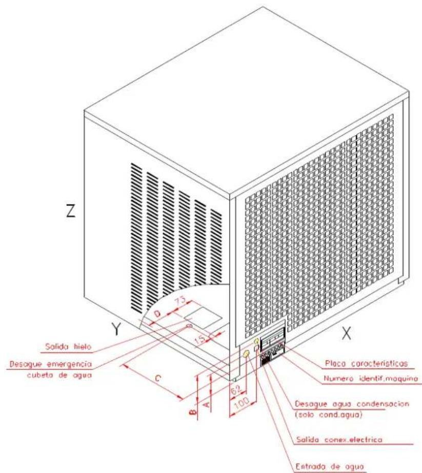
Rating Plate Serial number
Cooling water drain (water-cooled models)
Ice Electrical connection Wa Water inlet
| MODEL | COOLING WATER CONSUMPTION (L/Hour) | WATER CONSUMPTION (L/Hour) | NET WEIGHT (KG) | DIMENSIONS (CRATED) X*Y*Z | GROSS WEIGHT (KG) | VOLUME (M3) |
| IQ 150 A | 5.6 | 45 | 580x630x560 | 55 0.20 | ||
| IQ 150 W | 40 | 5.6 | 43 | 580x630x560 | 53 0.20 | |
| IQ 200 A | 8.5 | 52 | 580x630x645 | 60 0.23 | ||
| IQ 200 W | 60 | 8.5 | 50 | 580x630x645 | 58 0.23 | |
| IQ 400 A | 16 | 85 | 740x630x730 | 94 0.33 | ||
| IQ 400 W | 114 | 16 | 80 | 740x630x730 | 589 | 0.33 |
| IQ 550 A | 25 | 95 | 740x630x865 | 115 | 0.39 | |
| IQ 550 W | 177 | 25 | 93 | 740x630x865 | 113 | 0.39 |
| MODEL(gr) | REFRIGERANT CHARGE | HIGH PRESSURE | LOW PRESSURE AVERAGE | TOTAL AMPS(2)(A) (W) | FUSE RATING(W) | COMPRESSOR POWER(1) | TOTAL POWER(2) | ||||
| MINIMUM | MAXIMUM | ||||||||||
| Kg/cm_2 | Psi | Kg/cm_2 | Psi | Kg/cm_2 | Psi | ||||||
| IQ 150 A | 500 | 16 | 228 | 17 | 242 | 2.5 | 35 | 4.2 | 16 | 365 | 660 |
| IQ 150 W | 360 | 16 | 228 | 17 | 242 | 2.5 | 35 | 4.2 | 16 | 365 | 660 |
| IQ 200 A | 430 | 16 | 228 | 17 | 242 | 2.5 | 35 | 4.6 | 16 | 440 | 800 |
| IQ 200 W | 400 | 16 | 228 | 17 | 242 | 2.5 | 35 | 4.6 | 16 | 440 | 800 |
| IQ 400 A | 630 | 16 | 228 | 17 | 421 | 2.5 | 35 | 5.8 | 16 | 690 | 1100 |
| IQ 400 W | 440 | 16 | 228 | 17 | 242 | 2.5 | 35 | 5.8 | 16 | 690 | 1100 |
| IQ 550 A | 1050 | 16 | 228 | 17 | 242 | 2.5 | 35 | 9.2 | 20 | 1000 | 1700 |
| IQ 550 W | 1050 | 16 | 228 | 17 | 242 | 2.5 | 35 | 9.2 | 20 | 1000 | 1700 |
(1) Data obtained at room temperature (20°C), water introduced at 15°C; water quality = 500ppm
(2) Maximum consumption obtained at room temperature = 43°, according to UNE climate classification Class T (TROPICALISED).
NOTE: Expansion controlled by capillary, except for model IQ400 and 550 which is controlled by a thermostatic valve.
Models: ICE QUEEN 400 & 550 380V+III+N
| MODEL | REFRIGERAN T CHARGE 404 ^a (GR) | HIGH PRESSURE | LOW PRESSURE | TOTAL AMPS(2)(A) | FUSE RATING(A) | COMPRESSOR POWER(1)(W) | TOTAL POWER(2)(W) | ||||
| MÍNIMA | MÁXIMA | MEDIA | |||||||||
| Kg/cm _2 | Psi | Kg/cm _2 | Psi | Kg/cm _2 | Psi | ||||||
| IQ 400 A | 635 | 16 | 228 | 17 | 242 | 2.3 | 33.4 | 3.5 | 10 | 750 | 1350 |
| IQ 400 W | 635 | 16 | 228 | 17 | 242 | 2.3 | 33.4 | 3.5 | 10 | 750 | 1350 |
| IQ 550 A | 1500 | 16 | 228 | 17 | 242 | 2.3 | 33.4 | 5 | 16 | 2200 | 2x2700 |
| IQ 550 W | 1500 | 16 | 228 | 17 | 242 | 2.3 | 33.4 | 5 | 16 | 2200 | 2x2700 |
NOTE: Expansion controlled by a thermostatic valve.
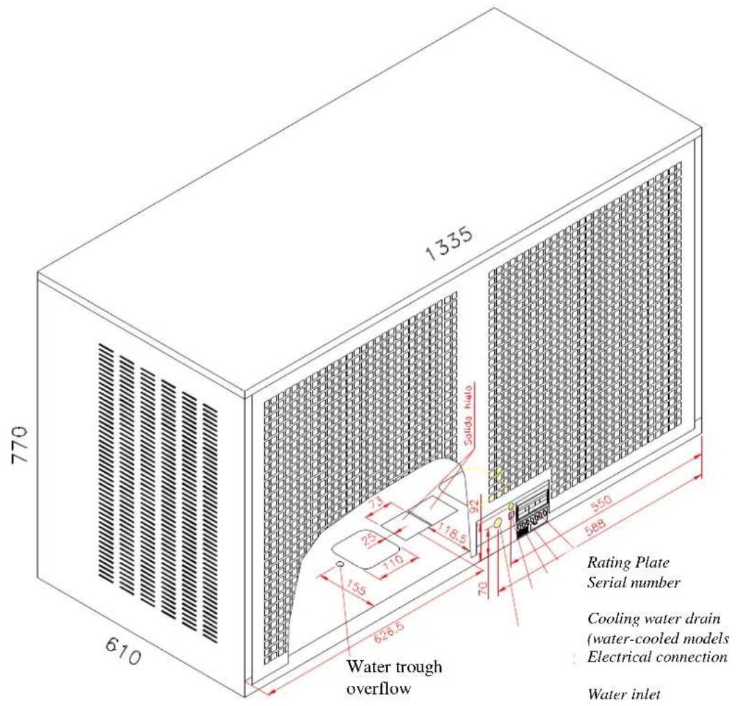
text_image
770 610 1335 Solid halo 7 20 118.5 92 155 110 626.5 70 550 588 Rating Plate Serial number Cooling water drain (water-cooled models Electrical connection Water inlet Water trough overflow| MODEL | COOLING WATER CONSUMPTION (L/Hour) | WATER CONSUMPTION (L/Hour) | NET WEIGHT (KG) | DIMENSIONS (CRATED) X*Y*Z | GROSS WEIGHT (KG) | VOLUME (M3) |
| IQ 1100 A | 50 | 192 | 1400x685x835 | 225 | 0.80 | |
| IQ 1100W | 354 | 50 | 185 | 1400x685x835 | 218 | 0.80 |
| MODEL | REFRIGERANT CHARGE(gr) | HIGH PRESSURE | LOW PRESSURE AVERAGE | TOTAL AMPS(2)(A) | FUSE RATING(A) | COMPRESSOR POWER(1)(W) | TOTAL POWER(2)(W) | ||||
| MINIMUM | MAXIMUM | ||||||||||
| Kg/cm^2 | Psi | Kg/cm^2 | Psi | Kg/cm^2 | psig | ||||||
| IQ 1100 A | 2x1500 | 16 | 228 | 17 | 242 | 2.5 | 35 | 9 | 2x16 | 2x2200 | 2x2700 |
| IQ 1100 W | 2x1500 | 16 | 228 | 17 | 242 | 2.5 | 35 | 9 | 2x16 | 2x2200 | 2x2700 |
(1) Data obtained at room temperature 20°C, water introduced at 15°C; water quality = 500ppm
(2) Maximum consumption obtained at room temperature = 43°, according to UNE climate classification Class T
(TROPICALISED).
NOTE: Expansion controlled by a thermostatic valve.
-Power inlet should be 3-phase III+N+T (380 V/50 HZ)
PRODUCTION TABLES FOR ICE FLAKERS
| IQ135A | |||||||||||||||||||||||||||||||||||||||||||||||||||||||||||||||||||||||||||||||||||||||||||||||||||||||||||||||||||||||||||||||||||||||||||||||||||||||||||||||||||||||||||||||||||||||||||||||||||||||||||||||||||||||||||||||||||||||||||||||||||||||||||||||||||||||||||||||||||||||||||||||||||||||||||||||||||||||||||||||||||||||||||||||||||||||||||||||||||||||||||||||||||||||||||||||||||||||||||||||||||||||||||||||||||||||||||||||||||||||||||||||||||||||||||||||||||||||||||||||||||||||||||||||||||||||||||||||||||||||||||||||||||||||||||||||||||||||||||||||||||||||||||||||||||||||||||||||||||||||||||||||||||||||||||||
| 45 | 104 | 1 | 02 | 96 | 92 | 86 | 82 | 78 | 106 | 104 | 9 | 9 | 94 | 8 | 8 | 84 | 80 | ||||||||||||||||||||||||||||||||||||||||||||||||||||||||||||||||||||||||||||||||||||||||||||||||||||||||||||||||||||||||||||||||||||||||||||||||||||||||||||||||||||||||||||||||||||||||||||||||||||||||||||||||||||||||||||||||||||||||||||||||||||||||||||||||||||||||||||||||||||||||||||||||||||||||||||||||||||||||||||||||||||||||||||||||||||||||||||||||||||||||||||||||||||||||||||||||||||||||||||||||||||||||||||||||||||||||||||||||||||||||||||||||||||||||||||||||||||||||||||||||||||||||||||||||||||||||||||||||||||||||||||||||||||||||||||||||||||||||||||||||||||||||||||||||||||||||||||||||||||||||||||
| 40 | 119 | 1 | 14 | 111 | 102 | 98 | 95 | 94 | 120 | 118 | 109 | 107 | 1 | 104 | 101 | 97 | 107 | 1 | 107 | 1 | |||||||||||||||||||||||||||||||||||||||||||||||||||||||||||||||||||||||||||||||||||||||||||||||||||||||||||||||||||||||||||||||||||||||||||||||||||||||||||||||||||||||||||||||||||||||||||||||||||||||||||||||||||||||||||||||||||||||||||||||||||||||||||||||||||||||||||||||||||||||||||||||||||||||||||||||||||||||||||||||||||||||||||||||||||||||||||||||||||||||||||||||||||||||||||||||||||||||||||||||||||||||||||||||||||||||||||||||||||||||||||||||||||||||||||||||||||||||||||||||||||||||||||||||||||||||||||||||||||||||||||||||||||||||||||||||||||||||||||||||||||||||||||||||||||||||||||||||||||||||||
| 35 | 134 | 1 | 24 | 118 | 115 | 110 | 106 | 102 | 129 | 122 | 119 | 119 | 117 | 115 | 113 | 104 | 30 | 136 | 1 | 34 | 123 | 120 | 111 | 109 | 106 | 137 | 128 | 123 | 123 | 120 | 118 | 115 | 112 | ||||||||||||||||||||||||||||||||||||||||||||||||||||||||||||||||||||||||||||||||||||||||||||||||||||||||||||||||||||||||||||||||||||||||||||||||||||||||||||||||||||||||||||||||||||||||||||||||||||||||||||||||||||||||||||||||||||||||||||||||||||||||||||||||||||||||||||||||||||||||||||||||||||||||||||||||||||||||||||||||||||||||||||||||||||||||||||||||||||||||||||||||||||||||||||||||||||||||||||||||||||||||||||||||||||||||||||||||||||||||||||||||||||||||||||||||||||||||||||||||||||||||||||||||||||||||||||||||||||||||||||||||||||||||||||||||||||||||||||||||||||||||||||||||||||||||||||
| IQ200 A | |||||||||||||||||||||||||||||||||||||||||||||||||||||||||||||||||||||||||||||||||||||||||||||||||||||||||||||||||||||||||||||||||||||||||||||||||||||||||||||||||||||||||||||||||||||||||||||||||||||||||||||||||||||||||||||||||||||||||||||||||||||||||||||||||||||||||||||||||||||||||||||||||||||||||||||||||||||||||||||||||||
| 45 | 192 | 1 | 84 | 168 | 156 | 144 | 13 | 8 | 118 | 330 | 325 | 3 | 10 | 30 | 0 | 280 | 251 | 232 | |||||||||||||||||||||||||||||||||||||||||||||||||||||||||||||||||||||||||||||||||||||||||||||||||||||||||||||||||||||||||||||||||||||||||||||||||||||||||||||||||||||||||||||||||||||||||||||||||||||||||||||||||||||||||||||||||||||||||||||||||||||||||||||||||||||||||||||||||||||||||||||||||||||||||||||||||
| 40 | 198 | 1 | 92 | 184 | 169 | 155 | 14 | 3 | 136 | 352 | 342 | 33 | 34 | 32 | 4 | 306 | 275 | 255 | 169 | ||||||||||||||||||||||||||||||||||||||||||||||||||||||||||||||||||||||||||||||||||||||||||||||||||||||||||||||||||||||||||||||||||||||||||||||||||||||||||||||||||||||||||||||||||||||||||||||||||||||||||||||||||||||||||||||||||||||||||||||||||||||||||||||||||||||||||||||||||||||||||||||||||||||||||||||||
| 35 | 204 | 1 | 96 | 190 | 176 | 168 | 15 | 4 | 142 | 370 | 360 | 35 | 4 | 33 | 8 | 313 | 287 | 275 | 376 | ||||||||||||||||||||||||||||||||||||||||||||||||||||||||||||||||||||||||||||||||||||||||||||||||||||||||||||||||||||||||||||||||||||||||||||||||||||||||||||||||||||||||||||||||||||||||||||||||||||||||||||||||||||||||||||||||||||||||||||||||||||||||||||||||||||||||||||||||||||||||||||||||||||||||||||||||
| 30 | 207 | 2 | 204 | 194 | 188 | 174 | 16 | 8 | 154 | 385 | 378 | 37 | 2 | 36 | 0 | 332 | 310 | 300 | 188 | ||||||||||||||||||||||||||||||||||||||||||||||||||||||||||||||||||||||||||||||||||||||||||||||||||||||||||||||||||||||||||||||||||||||||||||||||||||||||||||||||||||||||||||||||||||||||||||||||||||||||||||||||||||||||||||||||||||||||||||||||||||||||||||||||||||||||||||||||||||||||||||||||||||||||||||||||
| 25 | 210 | 2 | 206 | 202 | 191 | 187 | 17 | 4 | 167 | 400 | 395 | 37 | 8 | 36 | 0 | 343 | 325 | 308 | |||||||||||||||||||||||||||||||||||||||||||||||||||||||||||||||||||||||||||||||||||||||||||||||||||||||||||||||||||||||||||||||||||||||||||||||||||||||||||||||||||||||||||||||||||||||||||||||||||||||||||||||||||||||||||||||||||||||||||||||||||||||||||||||||||||||||||||||||||||||||||||||||||||||||||||||||
| 20 | 213 | 2 | 209 | 205 | 201 | 190 | 18 | 6 | 173 | 410 | 405 | 38 | 7 | 36 | 5 | 354 | 335 | 315 | |||||||||||||||||||||||||||||||||||||||||||||||||||||||||||||||||||||||||||||||||||||||||||||||||||||||||||||||||||||||||||||||||||||||||||||||||||||||||||||||||||||||||||||||||||||||||||||||||||||||||||||||||||||||||||||||||||||||||||||||||||||||||||||||||||||||||||||||||||||||||||||||||||||||||||||||||
| 15 | 221 | 2 | 211 | 208 | 205 | 200 | 19 | 0 | 185 | 418 | 409 | 40 | 0 | 37 | 5 | 365 | 346 | 326 | 10 | 224 | 2 | 220 | 211 | 208 | 204 | 19 | 8 | 188 | 430 | 420 | 4 | 12 | 39 | 5 | 380 | 360 | 340 | ||||||||||||||||||||||||||||||||||||||||||||||||||||||||||||||||||||||||||||||||||||||||||||||||||||||||||||||||||||||||||||||||||||||||||||||||||||||||||||||||||||||||||||||||||||||||||||||||||||||||||||||||||||||||||||||||||||||||||||||||||||||||||||||||||||||||||||||||||||||||||||||
| 5 | 10 | 15 | 20 | 25 | 30 | 35 | 5 | 10 | 15 | 20 | 25 | 30 | 35 | ||||||||||||||||||||||||||||||||||||||||||||||||||||||||||||||||||||||||||||||||||||||||||||||||||||||||||||||||||||||||||||||||||||||||||||||||||||||||||||||||||||||||||||||||||||||||||||||||||||||||||||||||||||||||||||||||||||||||||||||||||||||||||||||||||||||||||||||||||||||||||||||||||||||||||||||||||||||
| IQ550A | IQ1100A | ||||||||||||||||
| 45 | 470 | 450 | 420 | 400 | 370 | 360 | 345 | 1960 | 1940 | 1912 | 1816 | 1760 | 1656 | 1600 | |||
| 40 | 500 | 480 | 454 | 430 | 405 | 390 | 375 | 2064 | 2048 | 1976 | 1904 | 1800 | 1760 | 1656 | |||
| 35 | 520 | 540 | 490 | 455 | 435 | 425 | 405 | 2296 | 2232 | 2040 | 1976 | 1904 | 1800 | 1752 | |||
| 30 | 600 | 566 | 538 | 510 | 480 | 465 | 455 | 2360 | 2320 | 2248 | 2136 | 1960 | 1880 | 1792 | |||
| 25 | 611 | 568 | 549 | 522 | 500 | 486 | 471 | 2400 | 2376 | 2320 | 2232 | 2136 | 1960 | 1872 | |||
| 20 | 622 | 570 | 560 | 535 | 515 | 498 | 482 | 2436 | 2424 | 2400 | 2320 | 2224 | 2120 | 1960 | |||
| 15 | 626 | 589 | 567 | 540 | 520 | 502 | 488 | 2448 | 2432 | 2420 | 2384 | 2312 | 2224 | 2112 | |||
| 10 | 630 | 608 | 575 | 545 | 525 | 506 | 495 | 2480 | 2444 | 2432 | 2416 | 2384 | 2296 | 2200 | |||
| 5 10 | 15 20 | 25 30 | 35 | 5 10 | 15 20 | 25 30 | 35 | ||||||||||
WATER TEMPERATURE (°C)
Water quality = 500 ppm (240 Microhms/cm)
Kg/Day
About ice production
IMPORTANT: Production figures have been obtained under the following conditions:
Water Quality: 550 ppm. total solids
Water Temperature: 15°C
Ambient Temperature: 20°C
Ice production and quality is heavily dependent on the following:
a) Ambient temperature
b) Water temperature
c) Water quality
d) Level of water in evaporator
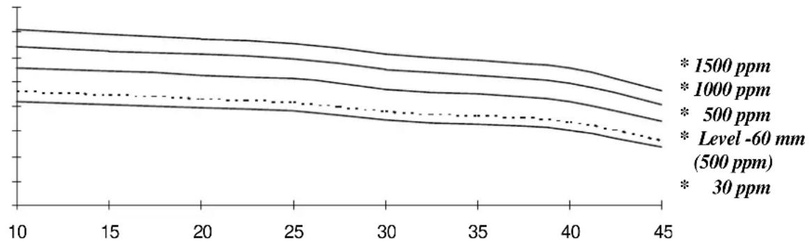
The following graph illustrates variations in production according to these factors. As shown, production decreases as water temperature increases.
IT IS IMPORTANT THAT WATER INTAKE TUBE IS NOT CLOSE TO ANY HEAT SOURCE. THIS WILL AFFECT ICE PRODUCTION AND QUALITY.
- Ambient temperature should be taken 4cm away from the centre of the front grille
- Water temperature should be taken inside the water trough. Check that water line and filter do not receive hot air from condenser + fan. If so, then re-direct water inlet line + filter to avoid hot air current.
- Ice quality can be improved by lowering the position of the water trough. The trough is attached to a panel with two screws. This panel has several slots, so that the trough can be moved up or down as required.
- The trough may be lowered up to 80mm (IQ 550/1100). This will result in decrease of production (see dotted line in graph below), but harder, drier ice.
• Water content in ice (obtained by straining ice) may be as much as 10% - Ice production also decreases with improved water quality. (See graph for approximate production variations).
Production Variations According to Water Quality When Water Temperature is Maintained at 15^ C.
line
| x | 1500 ppm | 1000 ppm | 500 ppm | Level -60 mm (500 ppm) | 30 ppm | |----|----------|----------|---------|------------------------|--------| | 10 | ~1.2 | ~1.1 | ~1.0 | ~1.0 | ~1.0 | | 15 | ~1.1 | ~1.0 | ~0.9 | ~0.9 | ~0.9 | | 20 | ~1.0 | ~0.9 | ~0.8 | ~0.8 | ~0.8 | | 25 | ~0.9 | ~0.8 | ~0.7 | ~0.7 | ~0.7 | | 30 | ~0.8 | ~0.7 | ~0.6 | ~0.6 | ~0.6 | | 35 | ~0.7 | ~0.6 | ~0.5 | ~0.5 | ~0.5 | | 40 | ~0.6 | ~0.5 | ~0.4 | ~0.4 | ~0.4 | | 45 | ~0.5 | ~0.4 | ~0.3 | ~0.3 | ~0.3 |Room temperature
DELIVERY & UNPACKING
Upon receipt, thoroughly inspect the packing container. If there appears to be damage to the container contact the shipper immediately. Unpack unit in the presence of delivery personnel noting any damage on the waybill.
ITV packing bears the “Green Point” on all models according to the European Directives on management of Packaging and Waste Disposal.
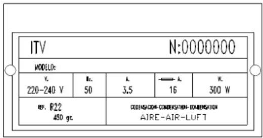
Be sure to include model name and serial number on all claims. Serial number is located in the following three places:
(1) Packing
There is a label stuck onto the cardboard packing bearing this serial number (1).
(2) Machine body
On the back of the machine (1).
(3) Rating plate and serial number
Located at the back of the machine.
Water cooled machines: check that the drainage hose at the back of the machine is in good condition.
Verify that the installation kit is inside the bin, and has the following pieces: scoop, 3/4' water hose, two small filters and user manual.
In all models there is a large particle filter (5 micres) with accessories, and an ice dispersion cone.
text_image
ITV N:0000000 MODEL: V. 220-240 V Rc. 50 A 3,5 —— A 16 W 300 W RF. P22 450 gr. CODENSICOM-COMENSATION-KOMBENSATION AIRE-AIR-LUFT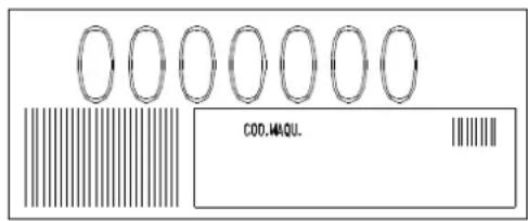
text_image
COO.MAQU.WARNING: DO NOT LEAVE PACKING
MATERIALS (PLASTIC BAGS, CARDBOARD BOXES, ETC.) WITHIN REACH OF CHILDREN.
INSTALLATION
Recommended Placement of Unit
IMPORTANT!
ICE QUEEN machines are intended to operate at room temperature between 5^ C and 43^ C and with water temperature ranging between 5^ C and 35^ C. You may encounter evaporator/gearbox malfunctions should the machine run at temperatures below the recommended minimum. When running above maximum recommended temperatures you can expect shorter compressor life and decreased production.
Air-cooled units receive air input via front of machine and expel air through rear grille.
IMPORTANT!
If front and/or rear ventilation is inadequate, obstructed, or in close proximity to other heat producing machinery, use of a water-cooled unit is strongly recommended.
The above mentioned also applies should unit be installed in an area where dust, smoke, or other airborne pollutants may be present. Units—especially air-cooled ones—should not be installed in kitchens. To facilitate access to condenser and/or water pressure valve, allow sufficient space at front of the machine. Ensure that flooring is firm and even.
Water and Drainage
Water quality influences ice hardness, flavour, and quality as well as condenser life.
Keep in mind the following points:
a) WATER IMPURITIES: Major impurities are eliminated by the two small wire mesh filters provided and installed on either end of the water inlet hose. Filters should be cleaned/replaced regularly depending on purity of water. For minor impurities we recommend installing a 5-micron filter such as the one provided with the unit: Part # ITV 207499. This filter will need to be replaced only when machine stops due to insufficient water flow (filter is obstructed with impurities).
b) WATER WITH MORE THAN 500 PPM: Ice will be less hard and tend to adhere. Lime deposits may impede proper function. In water-cooled models, condenser obstruction is likely. Installation of a high quality water softener is recommended.
c) CHLORINATED WATER: In most cases the filter which is included in the machine should be sufficient. However, if mains water smells or tastes of bleach, this indicates an excess of chlorine, which may eventually corrode the stainless steel auger. A carbon filter will remove chlorine in water (average filter life: 6 months), not included with machine. (Part # ITV 207509).
(NOTE: You may encounter water with ALL aforementioned properties.)
d) PURIFIED WATER: A 10% reduction in overall production may occur.
Connecting Unit To Water Source
- Use 1.3 m. flexible tube (with the two filters attached) provided. NOTE: We advise using a single faucet fixture.
• Water pressure should be between 0.7 and 6 Kgs/cm2. (10/85 Psi.) - If water pressure exceeds these values, installation of appropriate corrective units will be necessary.
- It is important that water tubing does not come close to or in contact with any heat sources or heat generated by unit as this could decrease production.
Connecting Unit To Drain (Water -cooled Models)
- Drain must be located at least 150mm below machine level. Drain tube must have an inner diameter of 30mm and a minimum gradient of 3 cm per metre.(3%)
Electrical connection
- Unit is provided with a 1.5 m cord and Schucko socket (except for models IQ550 and IQ1100).
- A switch and adequate fuses should be installed. Nominal voltage and intensity are indicated on rating plate as well as on this manual's technical pages. Voltage fluctuations greater than 10% can cause problems or prevent machine from starting.
- Line to base of plug must have a minimum section=2.5 mm2 for models up to IQ 200 and 4 mm2 for other models.
- Be sure voltage indicated on rating plate corresponds to that of mains supply.
IMPORTANT!
Supply socket must be properly earthed. Be sure to check standard for country where appliance is going to be installed.
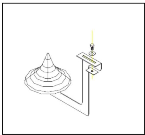
Assembling the dispersion cone
This device spreads ice evenly so it does not pile up beneath exit tube. Its position can be altered to redirect ice, and hence prevent the “pyramid effect”.
natural_image
Technical line drawing of a conical object with a vertical support and a light bulb, no text or symbols presentOPERATION
Preliminary Checks
a) Is machine levelled?
b) Are voltage and frequency of mains supply the same as indicated on rating plate?
c) Is drainage system working properly?
d) Is air circulation and room temperature adequate? (Air-cooled models)
AMBIENT TEMPERATURE
| MAXIMUM | 43°C |
| MINIMUM | 5°C |
WATER TEMPERATURE
| 35°C |
| 5°C |
e) Is water pressure adequate?
| MAXIMUM | 0.7 Kg/cm2 |
| MINIMUM | 6 Kg/cm2 |
ATENTION: Check that voltage and mains frequency is the same as in the rating plate.
Starting up
Once preliminary check has been completed (ventilation, connections, temperature, etc.), proceed as follows:
- Remove top cover of unit
- Open faucet, make sure there are no leaks and check that water level is adequate.
- Set switch to OFF position.
- Connect unit.
- Check for air bubbles in water supply tubing (water trough to evaporator)
IMPORTANT!
Be sure voltage and frequency of mains supply is as indicated on rating plate.
-
Set appliance switch to ON position. All elements should be working except for fan (air-cooled machines) which will commence operation only when high pressure activates it. All pilot lights should be switched off except for power display (green), indicating that power is on. Otherwise check the troubleshooting section of this manual.
-
Make sure fan blades don't come into contact with anything and that none of the tubes vibrate.
Inspection and Adjustment of Water Level in the Trough
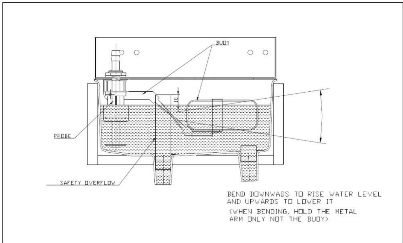
- Make sure water level in trough does not go down completely as this will set off "WATER LOW" sensor while machine is operating. Should this happen with a pressure higher than 1Kg/cm2 and filters in good condition, INCREASE LEVEL by bending the float arm upwards.
- Turn machine off and wait for flotation valve to close before water escapes through maximum level drain. If that happens and pressure is lower than 6kg./cm2, slowly bend and lower the float's arm until you have achieved an adequate flow.
IMPORTANT!
If water pressure exceeds 6 kg./cm2., a pressure reduction unit should be installed to maintain pressure at 4kg./cm2.
Cross Check
a) Shut off water faucet. Water level will recede until automatic shut-off occurs.
b) Open water faucet. Water level will rise and machine operations will commence in 3 minutes' time.
IMPORTANT!
Please instruct end user as to the correct maintenance procedures as described above. The manufacturer declines all responsibility for damage caused by failure to properly maintain the equipment.
ADJUSTMENTS
Expansion valve.
DO NOT TOUCH THE EXPANSION VALVE.
Water Level
The purpose of maintaining proper water levels is to allow adequate water flow to the evaporator. A water level sensor has been incorporated to shut off unit until required minimum water level is achieved.
The optimal water level is indicated in diagram below.
text_image
BEND DOWNWADS TO RISE WATER LEVEL AND UPWARDS TO LOWER IT (WHEN BENDING, HOLD THE METAL ARM ONLY NOT THE BUOY) PROBE SAFETY OVERFLOWPressure-controlled Valve on cooling water circuit
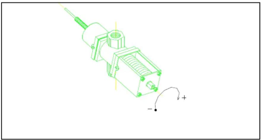
- The purpose of this valve is to control cooling water flow to the condenser, so as to maintain the high pressure at 16.5 bar (232-240 Psi), which corresponds to water temperature of 40^ (exit temperature).
- If mains water temperature exceeds 32^ , the above values of high pressure and water temperature at exit will be higher.
ADJUSTMENT: High pressure (and water temperature) can be decreased by opening valve (turn screw clockwise).
natural_image
Technical line drawing of a mechanical component with no visible text or symbolsFan pressostat (air-cooled models)
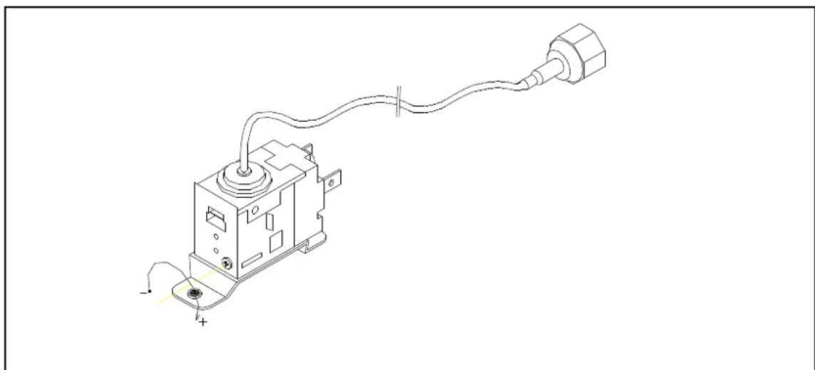
High pressure is controlled by starting and stopping fan, which provides airflow through condenser. Differential is fixed. (1Kg/cm2 or 14 Psi.) Cut-off pressure should be 16 Kg/cm2 (228 Psi.) Low pressure values in circuit may cause gearbox malfunction due to excessive ice production. Pressure values higher than 14 Kg/cm2 will diminish ice production and may shorten compressor life. Pressure can be regulated by rotating screw on Pressure Control Valve (clockwise to increase pressure). One full turn is equivalent to about 1.5 Kg/cm2.
natural_image
Technical line drawing of a mechanical device with wires and connectors (no text or symbols)Safety pressostat
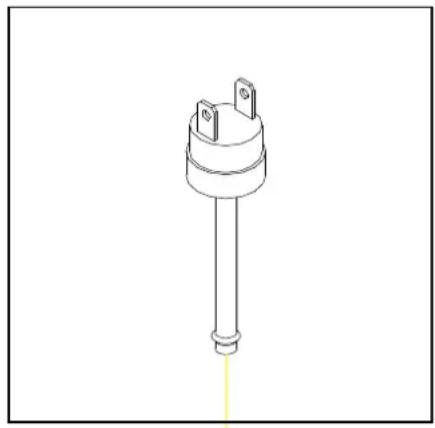
This safety device trips when pressure is too high. Pressure might re the set limit of 27 Kg/cm2 when:
a) Air circulation is not sufficient, room temperature is too high, cc is dirty or fan motor is broken. (air-cooled models)
b) Insufficient water in the cooling circuit, inlet water temperature is or fan motor is broken (water -cooled models).
The safety pressostat will switch off the machine completely until pi drops again to its lower set point value (21 Kg/cm2)
natural_image
Technical line drawing of a cylindrical electronic component with two pins and a shaft (no text or symbols)HIGH PRESSURE SET POINTS (non-adjustable):
27-21 Kg/cm2 (380-296 Psi.)
Start up timer
This timer delays start up for 2-3 minutes after machine is switched on. This delay allows ice formed on evaporator to partially melt. When the machine restarts ice will be wet and loose in evaporator, and hence gearbox/auger breakage risk is reduced.
THIS TIMER ONLY WORKS WHEN MACHINE IS WARM.
Safety devices.
- Overload protection device: will trip if maximum current intensity (A) is exceeded, hence preventing the motor from overheating due to current peaks. When overload trips, a red light will switch on in the front panel. The overload must be reset manually, to do so the front grille and overload cover must be removed.
- Thermal protection device: will trip if temperature in motor exceeds set point. When this device trips, the same red light will switch on in the front panel. In this case, however, reset is automatic.
- Low water level sensor: a magnetically activated sensor (buoy) located inside the water trough will switch off the machine should the level of water fall below the set minimum. A red light will switch on in the front panel labelled “low water level”. Reset is automatic.
- Bin full of ice: a micro-switch located at the top of the evaporator will stop the machine when the bin (and the ice discharge tube leading to the bin) is full of ice. An orange light will switch on in the front panel labelled "bin full". Reset is automatic.
INSPECTION AND REPLACEMENT PROCEDURES
Lower bearing
Materials needed:
- PHILLIPS N°2 Screwdriver
- M8 Screws (*)
- 5 mm Allen key
- Nylon head hammer
- No. 12-13 wrench
Procedure:
1) Disconnect unit.
2) Close faucet.
3) Remove square black plastic lower lid on machine base.
4) Remove drain plug on lower bearing.
5) Remove side screw that holds bearing with a 5 mm Allen key.
6) Introduce M8 50 mm screw in drain plug hole. Bearing will come out as you tighten screw.
7) Check for wear inside bearing and replace if more than 0.25 mm.
8) Replace o-rings, add silicone and grease, clean evaporator and reassemble.
IMPORTANT!
Side hole must be aligned with the one in evaporator, otherwise you will not be able to insert Allen screw in place.
1) Open water faucet and check for leaks.
2) Assemble unit and connect to power source.
3) IMPORTANT: DISCARD ICE PRODUCED DURING FIRST 15 MINUTES.
Speed Reducer (Gearbox)
Materials needed:
β Extractor
β M8 Screws
β No.12-13 monkey wrench (2)
β No.8-9 monkey wrench
β 6 mm Allen key
β M8 nuts (2)
Procedure:
1) Remove top screw on gearbox.
2) Remove the four screws that hold flange.
3) Remover gearbox using extractor
Assembly:
1) Lubricate motor axle with grease.
2) Place gearbox face up.
3) Screw in (*) screw, place washer and lower gearbox by tightening nut.
WARNING: Do not hammer.
1) Face up clamps socket.
2) Remove (*) screw.
Place washer and tighten until spindle is flush with gearbox axle.
Upper flange
Materials needed:
β Extractor
β PHILLIPS N°2 Screwdriver
β M8 Screws (110 mm)
β No.12-13 monkey wrench (2)
β No.8-9 monkey wrench
β 4, 5 and 6 mm Allen key
β M8 nuts (2)
Procedure:
1) Disassemble gearbox (see previous section)
2) Remove all four screws holding brackets.
3) Remove all three screws that keep plate and evaporator together.
4) Remove gearbox by hand or using extractor.
Assembly:
1) Clean lodging and neck plate.
2) Mount plate.
IMPORTANT: End of ice discharge flap must be to the right of evaporator's window.
IMPORTANT: Carefully lubricate seal lips (depending on model), avoid damaging them.
1) Replace the three evaporator/plate screws.
2) Replace brackets.
3) Reassemble gearbox. (see previous section)
Upper bearing (depending on the model)
Materials needed:
β Extractor
β PHILLIPS N°2 Screwdriver
β M8 Screws (110 mm)
β No.12-13 monkey wrench (2)
β No.8-9 monkey wrench
β 4, 5 and 6 mm Allen key
β M8 nuts (2)
1) Disassemble gearbox (see previous sections)
2) Disassemble plate/flange (see previous section)
3) Remove top seals.
4) Place and fix extracting ring.
5) Strike chisel placed over extracting ring using nylon head hammer.
Assembly:
1) Install new seals and lubricate (SHELL MULTIFAK EP2 TE code ITV420).
2) Secure bearing.
3) Mount plate.
IMPORTANT: Be careful not to damage seals. Lubricate seal lips with grease.
MAINTENANCE AND CLEANING INSTRUCTIONS
IMPORTANT!
**Maintenance and cleaning procedures as well as problems derived from failing to carry them out are not covered by the warranty.
Proper maintenance is essential to obtain favourable ice quality and optimum functioning of unit. Frequency depends on water quality and characteristics of room where unit is installed.
** Maintenance/cleaning procedures should take place at least once every six months. If concentration of air pollutants is high, complete procedures on a monthly basis.
MAINTENANCE TABLE:
| PROCEDURE | MONTHLY | QUARTERLY | BIANNUAL | YEARLY | BIENNIAL | DURATION |
| Air condenser cleaning | 0000 | 0000 | **** | **** | **** | 30 minutes |
| Water condenser cleaning | ##### | **** | 90 minutes | |||
| Lower bearing check | ##### | **** | 60 minutes | |||
| Upper bearing check | 90 minutes | |||||
| Water circuit cleaning | ##### | ##### | 45 minutes | |||
| Sanitary cleaning | ##### | ##### | 30 minutes | |||
| Motor reducer (gearbox) cleaning | 0000 | 0000 | 30 minutes | |||
| Motor reducer (gearbox) oil level | 60 minutes | |||||
| Water filter cleaning/replacement | 0000 | 0000 | 30 minutes | |||
| Upper bearing lubrication | 30 minutes | |||||
| Gearbox oil change | 60 minutes | |||||
| General unit cleaning | &&& | &&& | &&& | &&& | &&& | -- |
0000 Depending on room characteristics
Depending on water quality
&& Carried out by owner
**** Essential
Maintenance and cleaning procedures as well as problems derived from failing to carry them out ARE NOT COVERED BY THE WARRANTY. Service personnel will invoice you for travel expenses, time invested and materials required for maintenance and cleaning of unit.
MAINTENANCE AND CLEANING PROCEDURES
WARNING: Unit should always be disconnected during maintenance/cleaning procedures.
Water Condenser
1) Disconnect machine.
2) Close water faucet.
3) Disconnect water entry/exit from condenser.
4) Prepare a solution of 50% phosphoric acid in distilled water.
5) Distribute solution through condenser. (Solution is more effective at 35^-40^ ).
WARNING!
DO NOT USE HYDROCHLORIC ACID
Air Condenser
1) Disconnect machine.
2) Close water faucet.
3) Clean condenser using a vacuum cleaner, soft brush and/or low-pressure air.
Evaporator/Water Trough
1) Disconnect machine.
2) Remove drain plug situated in lower bearing of evaporator. Use a container to collect water.
3) Allow water to flow for 2 to 3 minutes.
4) Close water faucet and replace plug in evaporator.
5) Prepare a solution of 50% phosphoric acid in distilled water. Do not use hydrochloric acid. Slowly pour solution into water trough. (Solution is more effective at 35^-40^ ).
6) Allow solution to stand for 20 minutes.
7) Remove lower plug and empty trough. Replace plug.
8) Fill trough with solution to maximum capacity. Connect machine and wait for unit to automatically shut off when remaining liquid drains.
WARNING:\*\* Discard ice produced during cleaning procedure.
9) Disconnect machine, remove plug, open faucet and let water run for 2 to 3 minutes.
10) Close faucet, place plug, open faucet and connect the machine.
**At this point sanitary cleaning starts
11) Slowly add bleach to water trough for at least 5 minutes. Allow machine to make ice for at least 15 minutes.
WARNING:** Discard ice produced during cleaning procedure.
12) Disconnect unit, place cover and check for water leaks. Change seal in water plug if necessary.
13) Replace filters if necessary. (Machines provided with 5mm wire gauze filters).
14) Reconnect machine.
Cleaning the water inlet filters
These round wire gauze filters placed on either end of the water hose to mains, often become blocked in the first few days of use, especially when the plumbing installation is new. Clean them under a jet of water.
Checking for water leaks
This must be done whenever maintenance is carried out on the machine: check all water connections, braces, tubes and hoses in order to eliminate leaks and prevent breakages and flooding. Check that the valve closes tightly on models with an automatic cleaning system.
NOTE: You will observe that after a certain period of functioning (the running-in period), low-pressure pressostats may need to be adjusted. This second adjustment will be final.
RUNNING-IN CHECK
It is essential to service the machine after about 10 working days, or earlier if any incident has occurred.
CHECK:
- Water level
• Minimum high pressure (fan should stop at 35-37°C, equivalent to 5.25 bar, 67.5 psi) - By-pass opening at -21^ ± 0.5^ during the first few minutes after start-up
- Ice dispersion cone is spreading ice uniformly inside the bin.
- Refrigerant charge (when fan switches off, bubbles should appear at the sight glass, and return line to the compressor should be covered in frost right up to the weld). If high-pressure manometer is connected do not disconnect until you stop the machine and pressures have stabilised. Check that a large amount of gas has not been lost in connecting/disconnecting manometers, and use the shortest hoses you can find in H.P.
- Any gearbox oil leaks?
NOTE:
Newly installed electromechanical control devices will suffer variations in their adjustment caused by the machine's own functioning. Once a second adjustment of these devices is carried out, this should be good for several years. It is recommended, however, to check these devices yearly, this is best done between October to April.
SAFETY TRIP (CIRCUIT-BREAKER) IN NEW MACHINES WILL SWITCH OFF THE MACHINE DUE TO ONE OF THE FOLLOWING:
- Ambient temperature is below 5^
• Water temperature is below 5^ C - Evaporation temperature is below -20^
• Cooling temperature below +30°C
• Refrigerant charge slightly low
In the first three cases, so long as temperatures do not drop below 3^ C (machine limit), re-adjust fan pressostat to 42^ C and check that by-pass opens at -21^ C. In the last two cases bypass will open and close very often. Adjust bypass, fan pressostat and add refrigerant if necessary.
Gearbox current consumption should be between 1.9A (min) and 2.6A (peaks) with an average 2.2A. Safety trip will work at 2.4-2.6A and switch off the machine immediately.
If the machine is over 2 years old, also inspect the auger, bearings, and grease on bearings.
In case of excess current consumption, you can verify that the problem is in the gear-box by either physically detaching gearbox and motor from auger and checking current consumption, or by removing only the brown wire which provides current to the compressor.
In order to avoid damage to the gear-box, the safety trip is very sensitively adjusted and may trip easily. You may teach the end user to re-connect the machine (by inserting a pen/screwdriver through the front grille blades). This is best done after a one hour pause.
Should the machine trip on a regular basis (more than once a week), the end user must get in touch with the service department.
SPECIAL ADVICE CONCERNING R-404 REFRIGERANT
- R-404 is a mixture of 3 liquid-phase gases. On evaporating, the 3 component gases separate
- Always use the liquid phase valve (at the end of condenser or accumulator) for refills and purges.
- When replacing a compressor, wash inside of circuit with a suitable solvent + pump, dry with nitrogen gas, REPLACE THE DRIER WITH ONE SUITABLE FOR R-404, which must also have ANTI-ACID properties.
- If you need to add oil, use one which is specific for R-404 (POE). If you are in doubt, contact the machine manufacturer.
- If there is a leak anywhere in the circuit where R-404 in the GAS phase, and a refill of over 10% is required, then ALL THE GAS IN THE CIRCUIT MUST BE PURGED AND THEN REFILL AS DESCRIBED PREVIOUSLY (LIQUID PHASE VALVE)
- When charging via low-pressure valve, do not start compressor immediately, allow about one hour for liquid to gasify.
TROUBLESHOOTING
| PROBLEM | PROBABLE CAUSE | SOLUTION |
| 1) Machine not running. | A) There is no power. | A) Check power source. |
| B) Water trough is empty. | B) Check the water supply.Check filters.Open faucet | |
| C) “Full bin” sensor malfunction. | C) Fix/replace sensor. | |
| D) No apparent cause. | D) Check: contactor, circuit,breaker, pressostat, timer,electric installation and magnetic micro | |
| E) Timer is faulty. | E) Replace. | |
| 2) Machine works, but doesn’t make ice. | A) Refrigerant leak. | A) Repair leak and recharge refrigerant . |
| B) Faulty compressor. | B) Replace compressor. | |
| C) valvula de expansion cerrada o estropeada or capillary obstructed | C) Open or Replace valve (or capillary) and dehydrating filter. | |
| D) Water/humidity in refrigerating system. | D) Charge compressor oil,replace capillary and dehydrator(use an anti-acid one), create a vacuum in the installation, slightly warm up all components and charge refrigerant. | |
| 3) Machine works inconsistently | A) Water pressure lower than 0’7 BAR(pressure may sometimes drop greatly when several taps are opened elsewhere in premises) | A) For smaller units try regulating the water trough float. Larger machines might require installation of a mains pressure raising unit. |
| B) Water pressure is appropriate (0’7 a 6’5 BAR) | B) Regulate water level in trough. | |
| 4) Compressor works in intermittent manner. | A) Condenser is dirty | A) Clean condenser. |
| B) Air circulation obstructed. | B) Re-establish air circulation. | |
| C) Defective condenser fan. | C) Check and replace fan. | |
| D) Fan pressostat is defective or needs adjustment. | D) Check and replace/adjust | |
| E) Safety pressostat is defective. | E) Check and replace. | |
| F) Compressor start system is defective. | F) Check and replace. | |
| G) Pressostat valve is defective or needs adjustment. | G) Adjust, repair or replace valve. | |
| H) Voltage too low/insufficient line section | H) Inspect and replace if necessary. | |
| 5) Ice is too wet. | A) Room temperature too high (over 35°C) | A) Relocate unit to a cooler place. |
| B) Water temperature too high (over 30°C). | B) Ensure that filter and inlet tube are away from heat sources,such as hot air blown by machine’s own fan. | |
| C) Poor water quality (over 1500 ppm) | C) Lower the water trough. Install water purifier. | |
| D) Condenser is dirty. | D) Clean condenser. | |
| E) Pressure-controlled valve on cooling water needs adjustment or is defective. | E) Adjust or replace valve. | |
| F) Low compressor output | F) Replace compressor. | |
| G) Refrigerant leak | G) Repair leak and recharge refrigerant. | |
| H) Water level in trough is low. Water consumption is greater than buoy valve pass. | H) Check water pressure. Look for obstruction in filters or valve. Adjust water level in trough | |
| PROBLEM | PROBABLE CAUSE | SOLUTION |
| 6) Water leaks | A) Water from trough overflows and falls into ice bin. Buoy valve does not close. | A) Adjust water level. Reduce water pressure. Clean or replace valve. |
| B) Defective o-rings in lower bearing. | B) Seal with silicone or replace. | |
| 7) Machine is unusually noisy | A) Defective fan or loose blades | A) Tighten blades or replace fan. |
| B) Vibrating components | B) Tighten loose parts | |
| C) Compressor makes noise. | C) Replace compressor | |
| 8) Motor is unusually noisy | A) Back fan within motor is loose | A) Open motor and tighten fan. |
| B) Worn ball bearings. | B) Replace ball bearings or motor. | |
| 9) Gearbox is unusually noisy | A) Defective/worn parts within gearbox | A) Open gearbox and replace defective parts, or replace entire gearbox. |
| 10) Evaporator is unusually noisy | A) Upper or lower bearings are defective or dirty. | A) Replace, clean and/or lubricate bearings. |
| B) Auger and/or evaporator are scratched. | B) Check and replace if necessary. | |
| 11) Machine not working. Red pilot light is switched on in front panel. | A) Input voltage subject to oscillation which trips the machine. | A) Check voltage and rearm circuit breaker. Need a voltage stabiliser? |
| B) Electrical condenser on motor is faulty | B) Replace electrical condenser | |
| C) Condensation pressure in refrigeration circuit is too low | C) Adjust fan pressostat (air-cooled models) or cooling-water control valve (water-cooled models) | |
| D) Evaporation pressure (and temperature) too low | D) Adjust fan pressostat (air-cooled models) or cooling-water control valve (water-cooled models), check refrigerant charge and expansion valve setting if applicable. | |
| E) Lower or upper bearing is damaged and auger may be scratching evaporator. | E) Replace damaged bearing(s). Look for scratches on the bearings and on the vertical grooves inside evaporator. Check auger blade for sharpness and scratches | |
| F) Defective/worn parts within gearbox | F) Open gearbox and replace faulty parts, or replace entire gearbox. | |
| G) Bearing on motor reducer is blocked. | G) Repair or replace motor. | |