MS-N5016-UT - Video recorder Milesight - Free user manual and instructions
Find the device manual for free MS-N5016-UT Milesight in PDF.


User questions about MS-N5016-UT Milesight
0 question about this device. Answer the ones you know or ask your own.
Ask a new question about this device
Download the instructions for your Video recorder in PDF format for free! Find your manual MS-N5016-UT - Milesight and take your electronic device back in hand. On this page are published all the documents necessary for the use of your device. MS-N5016-UT by Milesight.
USER MANUAL MS-N5016-UT Milesight
These instructions are intended to ensure that user can use the product correctly to avoid danger or property loss. The precaution measures are divided into "Warnings" and "Cautions"
Warnings: Serious injury or death may be caused if any of these warnings is neglected.
Cautions: Injury or equipment damage may be caused if any of these cautions are neglected.
 |  |
| Warnings: Please follow these safeguards to prevent injury or death. | Cautions: Please follow these safeguards to prevent potential injury or material damage |

Warnings
This installation must be conducted by a qualified service person and should strictly comply with the electrical safety regulations of the local region
◆ To avoid risk of fire and electric shock, do keep the product away from rain and moisture
Do not touch components such as heat sinks, power regulators, and processors, which may be hot
◆ Source with DC 12V or PoE
◆ Please make sure the plug is firmly inserted into the power socket
When the product is installed on a wall or ceiling, the device should be firmly fixed
◆ If the product does not work properly, please contact your dealer. Never attempt to disassemble the camera by yourself

Cautions
◆ Make sure that the power supply voltage is correct before using the camera
Do not store or install the device in extremely hot or cold temperatures, dusty or damp locations, and do not expose it to high electromagnetic radiation
◆ Only use components and parts recommended by manufacturer
◆ Do not drop the camera or subject it to physical shock
◆ To prevent heat accumulation, do not block air circulation around the camera
◆ Laser beams may damage image sensors. The surface of image sensors
should not be exposed to where a laser beam equipment is used
◆ Use a blower to remove dust from the lens cover
Use a soft, dry cloth to clean the surface of the camera. Stubborn stains can be removed using a soft cloth dampened with a small quantity of detergent solution, then wipe dry
Do not use volatile solvents such as alcohol, benzene or thinners as they may damage the surface finishes
◆ Save the package to ensure availability of shipping containers for future transportation
EU Conformity Statement

2012/19/EU (WEEE directive): Products marked with this symbol cannot be disposed of as unsorted municipal waste in the European Union. For proper recycling, return this product to your local supplier upon the purchase of equivalent new equipment, or dispose of it at designated collection points. For more information see: www.recyclethis.info.

2006/66/EC (battery directive): This product contains a battery that cannot be disposed of as unsorted municipal waste in the European Union. See the product documentation for specific battery information.
The battery is marked with this symbol, which may include lettering to indicate cadmium (Cd), lead (Pb), or mercury(Hg). For proper recycling, return the battery to your supplier or to a designated collection point. For more information see: www.recyclethis.info.
Content
1. Product Introduction......1
1.1 Introduction....1
1.2 Product Key Functions....1
2. Hardware....5
2.1 Panel Buttons and Lights Instructions....5
2.2 Using a USB Mouse 8
2.3 Hard Disk Installation....8
2.3.1 MS-N7000 series Hard Disk Installation....8
2.3.2 MS-N8000 series Hard Disk Installation....12
3. Local Operation....16
3.1 Wizard Setting....16
3.2 Playback....18
3.2.1 Video Playback....18
3.2.2 Video Files Backup....20
3.2.3 Picture Playback....21
3.2.4 Picture Files Backup 22
3.3 Camera Settings....23
3.3.1 Camera Management....23
3.3.2 Device Search....29
3.3.3 PTZ Configuration....29
3.3.4 Privacy Mask....33
3.3.5 OSD configuration....35
3.3.6 Image Enhancement....36
3.4 Record Settings....37
3.4.1 Record Mode....37
3.4.2 Record Schedule Setting 38
3.4.3 Advanced settings....42
3.5 Event Settings....42
3.5.1 Motion Detection....42
3.5.2 Video Loss....47
3.5.3 Alarm Input....50
3.5.4 Alarm Output....51
3.5.5 Exception....53
3.6 Status....53
3.6.1 Device Information....53
3.6.2 Network Status....54
3.6.3 Camera Status....54
3.6.4 Disk Status....55
3.6.5 Event Status....55
3.7 Live View Settings....56
3.7.1 Live View....56
3.7.2 Layout Configuration....58
3.7.3 Live View Parameter....59
3.8 System Settings....59
3.8.1 General Setting....59
3.8.2 Network Settings....60
3.8.3 Disk Management....65
3.8.4 Holiday Configuration....67
3.8.5 User Account Settings....68
3.8.6 Upgrade....70
3.8.7 Save/Load Configuration....72
3.8.8 Auto Maintenance....74
3.8.8 Auto Reboot....74
3.9 Shutdown....75
3.9.1 Logout....75
3.9.2 Reboot....75
3.9.3 Shutdown....75
3.9.4 Close....75
- WEB Settings....76
4.1 Login 76
4.2 Live View....76
4.2.1 Camera List....76
4.2.2 Play View....77
4.2.3 PTZ....78
4.2.4 Video Parameters....78
4.3 Playback....78
4.3.1 Playback....78
4.3.2 Video Files Backup....80
4.3.3 Picture Files Backup....81
4.4 Logs....81
4.5 Settings....82
4.5.1 Local Configuration....82
4.5.2 Camera....83
4.5.3 Record....91
4.5.4 System....95
4.5.5 Event....105
4.6 Status....108
4.6.1 Device Information....108
4.6.2 Network Status....109
4.6.3 Camera Status....109
4.6.4 Disk Status....109
4.6.5 Event Status....110
4.6.6 Packet Capture Tool....110
4.7 Logout....111
- Services....112
1. Product Introduction
1.1 Introduction
Milesight NVR Series are based on embedded linux operating system, and they are positioned at management and storage application of HD video data, and own multi-disc management systems, front end HD device management system, HD video analysis system and high-capacity system for video. It adopts the technology of high flow capacity data network transmitting&transmission, with multi-channel video decoding, to achieve functions like intelligent management, safe storage, HD decoding, etc.
1.2 Product Key Functions
Basic Information
● Milesight NVR Series includes MS-N1000-U(P)T, MS-N5000-U(P)T, MS-N5000-UH, MS-N7000-U(P)H, MS-N8000-UH, can work with network cameras and connect with third party network cameras which support ONVIF.
Monitoring
● Support HDMI video output.
- For UHD HDMI display, maximum to 3840*2160 resolution.
● Support 1/4/8/9/12/14/16/32 screen live view, channel sequence is adjustable.
● Support live view fast menu operation.
● Support live view group switch, manual switch and automatic patrol. The interval of automatic sequence is adjustable.
● Support motion detection and video loss alert.
● Support various PTZ protocols, PTZ preset, auto patrol and pattern.
● Support central zoom in by clicking the mouse at arbitrary area.
● Support privacy mask.
● Support OSD title and date configuration.
● Equipped with PoE ports for PoE cameras(only available for PoE NVR).
HDD Management
● Support S.M.A.R.T technology.
● Support RAID technology.
Recording/Snapshot and Playback
● Support holiday schedule.
● Support recycle and non-recycle recording mode.
● Support multiple recording types, including timing, alarm, motion detection, motion or
alarm, motion and alarm, etc.
● Support 12 recording time periods with separate recording types.
● Support pre-record and post-record time for motion detection, alarm recording, motion and alarm recording, motion or alarm recording. And support pre-record for manual and timing.
● Support recording/snapshot manually.
● Support digital zoom function at arbitrary area in playback.
● Support video data playback.
● Support pause, fast play, slow play, skip forward and skip backward when playback, locating in progress bar by dragging the mouse.
Backup
● Support USB port backup.
● Support FAT32 format backup.
● Support backup device maintenance and management.
Alarm & Exception
● Support video loss alarm.
● Support motion detect configure and alarm.
● Support Network Disconnected/HDD Full/Record Failed/HDD Failed/HDD Unformat/No Disk alarms.
● Support various alarm response such as audible warning, sending email, recording and on/off relay out.
Other Functions
● Support multi-level user management, administrator can create multiple users with access rights.
● Support manual triggering and clearing of alarms.
● Support operating and configuring information import/export.
Network
● Support remote search, playback and download of video files.
● Support remote acquiring and configuring of parameters.
● Support remote import and export of device parameters.
● Support P2P remote access.
● Support remote acquiring of device status, system log and alarm status.
● Support remote operate system maintenance by format of hard disk, upgrade and auto reboot, etc.
● Support upload alarm and exceptions to remote host.
● Support remote manual start or stop of recording.
● Support remote manual start or stop of alarm output.
● Support remote BMP image capturing.
● Support remote PTZ control.
● Built-in WEB Server.
| Model | MS-N1009-UT | MS-N5016-UT | MS-N5016-UH/MS-N5032-UH | MS-N7016-UH/MS-N7032-UH | MS-N8032-UH/MS-N8064-UH | ||
| Video/Audio Input | Network Video Input | 9 | 16 | 16/32 | 16/32 | 32/64 | |
| Max. Stream | 90Mbps | 160Mbps | 160/320Mbps | 160/320Mbps | 320Mbps | ||
| Network Audio Input | 9 | 16 | 16/32 | 16/32 | 32/64 | ||
| Analog Audio Input | — | — | 1*RCA | 1*RCA | 1*RCA | ||
| Video/Audio Output | HDMI Output | 1 | 1 | 1 | 1 | 2 | |
| VGA Output | — | 1 | 1 | 1 | 2 | ||
| Audio Output | — | 1*RCA | 1*RCA | 1*RCA | 2*RCA | ||
| 30fps@D1(704×576) | 9 | 16 | 16/32 | 16/32 | 32/64 | ||
| 30fps@720P(1280×720) | 9 | 16 | 16/32 | 16/32 | 32 | ||
| 30fps@1080P(1920×1080) | 8 | 8 | 16 | 16 | 16 | ||
| Synchronous Preview / Synchronous Playback | 30fps@3MP(2048×1536/2304×1296) | 5 | 5 | 10 | 10 | 10 | |
| 20fps@4MP(2592×1520) | 4 | 4 | 8 | 8 | 8 | ||
| 20fps@5MP(2560×1920) | 3 | 3 | 6 | 6 | 6 | ||
| 30fps@6MP(3072×2048) | 2 | 2 | 5 | 5 | 5 | ||
| 30fps@2160P(3840×2160) | 2 | 2 | 4 | 4 | 4 | ||
| 30fps@2160P(4096×2160) | — | — | 4 | 4 | 4 | ||
| Video/Audio Compression | Video Compression | H.265(HEVC)/H.264 | |||||
| Recording Resolution | 8MP(UHD-2160P)/4MP/3MP/1080P/UXGA/720P/D1/VGA/CIF/QCIF | ||||||
| Max Synchronous Recording | 9(5MP) | 16(5MP) | 16/32(5MP) | 16/32(5MP) | 32/64(5MP) | ||
| Storage | SATA | 2SATA 2.5” HD with 2TB each | 2SATA 3.5” HD with 10TB each | 2SATA 3.5” HD with 10TB each | 4SATA 3.5” HD with 10TB each | 8SATA 3.5” HD with 10TB each | |
| External Storage | — | — | — | — | 1 eSATA | ||
| Interface | USB | 2*USB 2.0 | 1*USB 3.0; 2*USB 2.0 | ||||
| Alarm Input/Output | — | 4-CH/1-CH | — | 16-CH/4-CH | |||
| Model | MS-N1009-UPT | MS-N5016-UPT | MS-N7032-UPH | ||
| Video/Audio Input | Network Video Input | 9 | 16 | 32 | |
| Max. Stream | 90Mbps | 160Mbps | 320Mbps | ||
| Network Audio Input | 9 | 16 | 32 | ||
| Analog Audio Input | — | - | 1*RCA | ||
| Video/Audio Output | HDMI Output | 1 | 1 | 1 | |
| VGA Output | — | 1 | 1 | ||
| Audio Output | — | 1*RCA | 1*RCA | ||
| 30fps@D1(704×576) | 9 | 16 | 32 | ||
| 30fps@720P(1280×720) | 9 | 16 | 32 | ||
| 30fps@1080P(1920×1080) | 8 | 8 | 16 | ||
| Synchronous Preview / Synchronous Playback | 30fps@3MP(2048×1536/2304×1296) | 5 | 5 | 10 | |
| 20fps@4MP(2592×1520) | 4 | 4 | 8 | ||
| 20fps@5MP(2560×1920) | 3 | 3 | 6 | ||
| 30fps@6MP(3072×2048) | 2 | 2 | 5 | ||
| 30fps@2160P(3840×2160) | 2 | 2 | 4 | ||
| Video/Audio Compression | Video Compression | H.265(HEVC)/H.264 | H.265(HEVC)/H.264 | H.265(HEVC)/H.264 | |
| Recording Resolution | 8MP(UHD-2160P)/4MP/3MP/1080P/UXGA/720P/D1/VGA/CIF/QCIF | ||||
| Max Synchronous Recording | 9(5MP) | 16(5MP) | 32(5MP) | ||
| Storage | SATA | 1SATA 3.5” HDDwith 10TB each | 2SATA 3.5” HDDwith 10TB each | 4SATA 3.5” HDDwith 10TB each | |
| Interface | USB | 2*USB 2.0 | 1*USB 3.0; 2*USB 2.0 | 1*USB 3.0; 2*USB 2. | |
| Alarm Input/Output | — | — | 16-CH/4-CH | ||
| PoE Interface | 4*RJ45 10M/100M | 8*RJ45 10M/100M | 16*RJ45 10M/100M | ||
2. Hardware
2.1 Panel Buttons and Lights Instructions
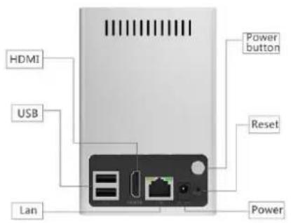
(1) MS-N1000-UT Series: MS-N1009-UT
text_image
HDMI USB LAN Power button Reset PowerMS-N1009-UT
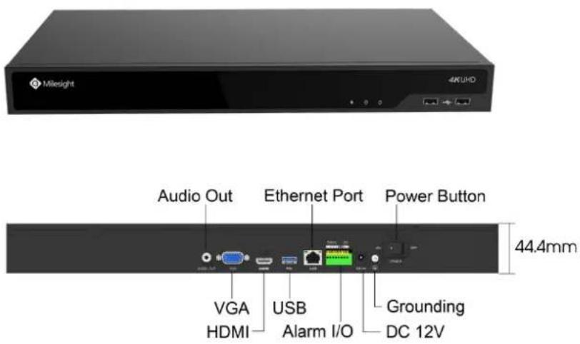
(2) MS-N5000-UT Series: MS-N5016-UT
text_image
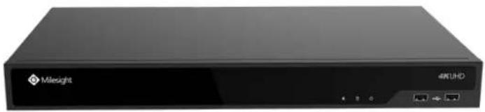
Milesight 4KUHD Audio Out Ethernet Port Power Button 44.4mm VGA HDMI USB Alarm I/O Grounding DC 12V(3) MS-N5000-UH Series: MS-N5016-UH/MS-N5032-UH
natural_image
Exterior view of a black wireless router labeled 'Milesight' with ports and indicator lights (no readable text beyond branding)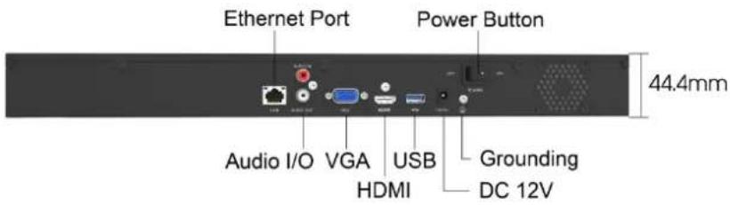
text_image
Ethernet Port Power Button Audio I/O VGA USB Grounding HDMI DC 12V 44.4mm(4) MS-N7000-UH Series: MS-N7016-UH/MS-N7032-UH
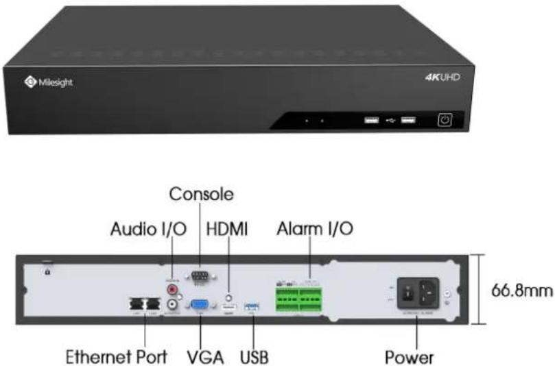
text_image
Milesight 4KUHD Console Audio I/O HDMI Alarm I/O Ethernet Port VGA USB 66.8mm Power(5) MS-N8000-UH Series: MS-N8032-UH/MS-N8064-UH
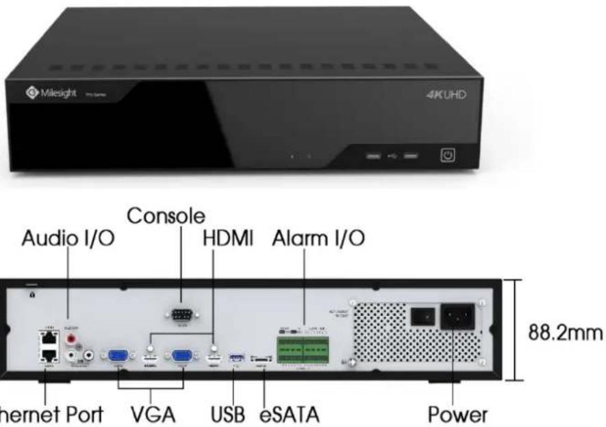
text_image
Milesight Pro Series 4KUHD Audio I/O Console HDMI Alarm I/O 88.2mm Internet Port VGA USB eSATA Power(6) MS-N1000-UPT Series: MS-N1009-UPT
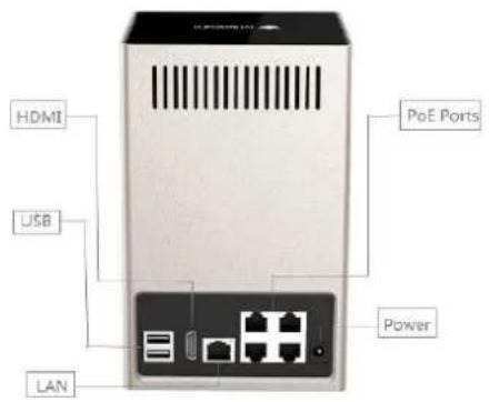
text_image
HDMI USB LAN PoE Ports Power(7) MS-N5000-UPT Series: MS-N5016-UPT

text_image
Milesight 4KUHD PoE Ports VGA USB HDMI Alarm I/O Audio Output Ethernet Port Power 44.4mm(8) MS-N7000-UPH Series: MS-N7032-UPH

text_image
Milesight 4KUHD PoE Ports Audio I/O RS-232 HDMI Alarm I/O Ethernet Port VGA USB Power 66.8mmNote:
The PoE ports of PoE NVR series only support Milesight network cameras.
2.2 Using a USB Mouse
| Item | Click | Description |
| Left Button | Single- click | Live view: select the channel and show the toolbar of live vMenu: select and confirm. |
| Double-click | Switch between single screen to multi-screen when in live vi mode and playback mode. | |
| Click and drag | (1) Control rotation direction in PTZ mode.(2) Set the target area in tamper-proof, motion detection ar privacy mask alarm settings.(3) Drag the digital zoom area.(4) Drag the channel and the time scroll bar. | |
| Right Button | Single-click | Live view: shows pop-up menu.Menu: exit and go to previous menu. |
| Scroll-wheel | Scroll up | Scroll up the page. |
| Scroll down | Scroll down the page. |
2.3 Hard Disk Installation
2.3.1 MS-N7000 series Hard Disk Installation
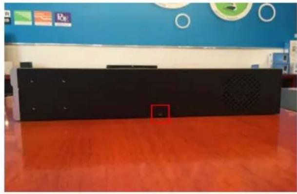
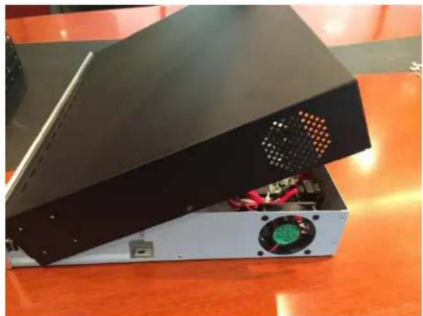
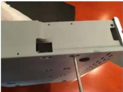
Step1. Unscrew the back and both sides' screws to open the upper lid.
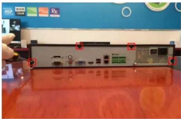
natural_image
Back view of a computer drive chassis with ports and connectors, placed on a red surface (no visible text or symbols)F-2.5.1
natural_image
Interior view of a modern office or library space with blue walls, orange flooring, and a black electronic device (no visible text or symbols)F-2.5.2
natural_image
Stacked electronic equipment with visible fan and circuit board (no text or symbols)F-2.5.3
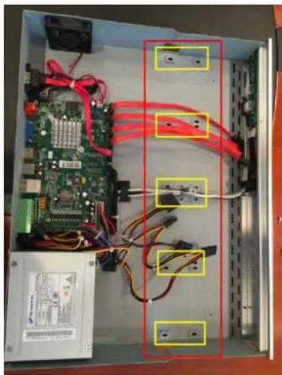
Step2. Install the hard disks into NVR with screws shown in below pictures. (SATA Slots of hard disk should be toward inside NVR.)
natural_image
Interior view of an electronic control panel with visible circuit boards, cables, and connectors (no text or symbols)F-2.5.4
natural_image
Close-up of a white electronic device with black components and mounting holes, mounted on a metal stand against an orange background (no visible text or symbols)F-2.5.5
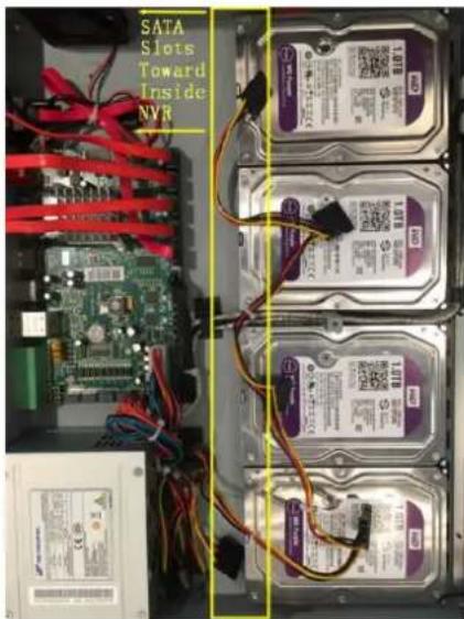
text_image
SATA Slots Toward Inside NVRF-2.5.6
Step3. Join the power and data connectors to corresponding hard disk.
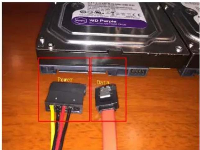
text_image
WD Purple Power DataF-2.5.7
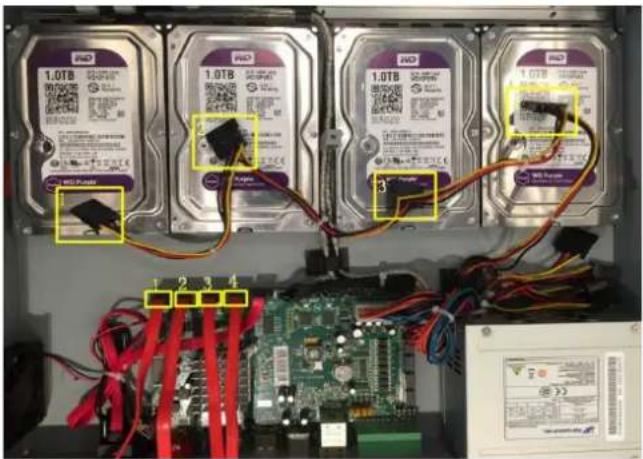
text_image
1.0TB 1.0TB 1.0TB 1.0TB 1.0TB 1.0TB 3 2 3 4F-2.5.8
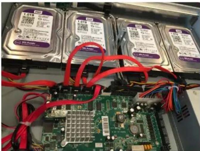
natural_image
Close-up of a computer motherboard with multiple hard disk drives and red circuitry (no readable text or symbols)F-2.5.9
2.3.2 MS-N8000 series Hard Disk Installation
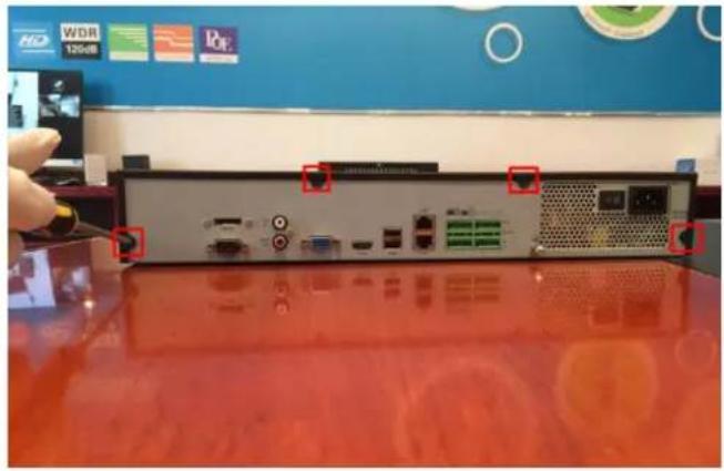
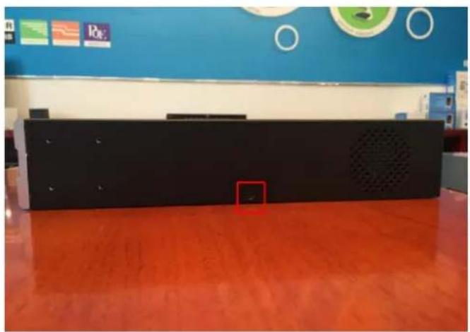
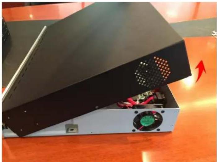
Step1. Unscrew the back and both sides' screws to open the upper lid.
natural_image
Back view of a computer interface unit with ports and connectors, placed on a red surface (no visible text or symbols)F-2.5.10
natural_image
Interior view of a modern office or service center with blue walls, orange flooring, and a black electronic device panel (no visible text or symbols)F-2.5.11
natural_image
Exterior view of an electronic device with a fan and power strip, placed on a wooden table (no visible text or symbols)F-2.5.12
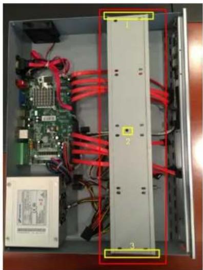
Step2. Uninstall the upper hard disk panel.
natural_image
Interior view of an electronic control panel with visible circuit board, red cables, and a central drive (no text or symbols)F-2.5.13
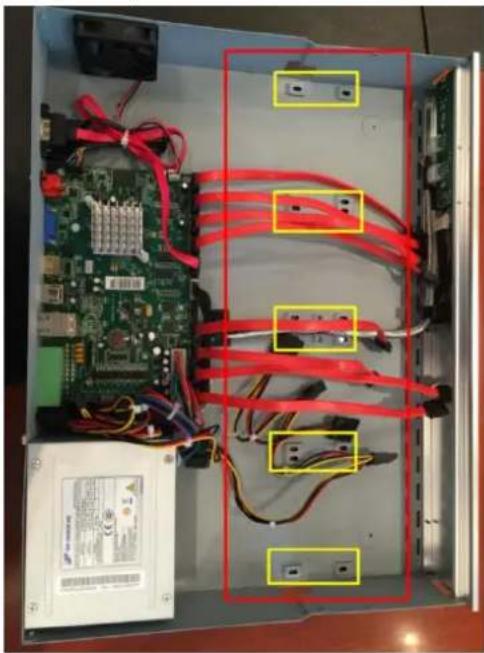
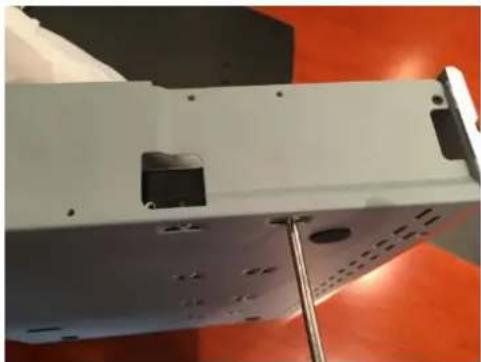
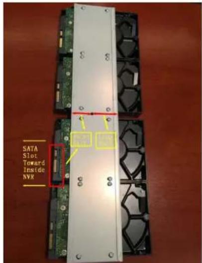
Step3. Install the hard disks into NVR with screws shown in below pictures.(SATA slots of hard disks should be toward inside NVR)
natural_image
Interior view of an electronic device showing a circuit board, power input, and red-labeled connectors (no text or symbols visible)F-2.5.14
natural_image
Close-up of a white electronic device with black mounting holes and a metallic stand, set against an orange background (no visible text or symbols)F-2.5.15

text_image
SATA Slots Toward Inside NVRF-2.5.16
text_image
SATA Slot Toward Inside NVXF-2.5.17
Note:
The SATA slots are in SHORT HALF side and the SATA slot toward inside NVR.
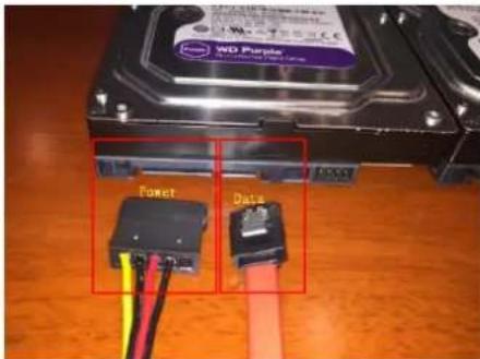
Step4. Join the power connectors to corresponding hard disks.(Install lower hard disk panel before upper one)
text_image
WD Purple Power DataF-2.5.18
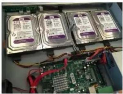
natural_image
Interior view of an ATM drive bay with four hard drives and a circuit board (no visible text or labels)F-2.5.19
Step5. Join the data connectors to corresponding hard disk.(Check the connection by below sequence)
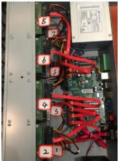
text_image
Internal view of a computer motherboard with numbered electronic components and wiring, showing circuit board connections and labeled parts.F-2.5.20
Note:
The data connector sequence of MS-N7000 series is different from MS-N8000 series'.
3. Local Operation
3.1 Wizard Setting
By default, the Setup Wizard will start once the NVR has loaded. The Setup Wizard will guide you to complete important settings to make sure the device function well. You can choose if the Setup Wizard starts or not every time when the device powered.
Please complete the configuration as following:
Step1. Input the user name and password;
If you want to modify the admin password, input the new password.
Note:
-
If the NVR firmware version out of the factory is xx.7.0.6 or above, the default user name is "admin" and the default password is "ms1234";
-
If the NVR firmware is upgraded to xx.7.0.6 or above from a lower version, the default password will turn to "ms1234" after a reset, or it will keep the old default password "123456";
-
If the NVR firmware version is below xx.7.0.6, the default user name is "admin" and the default password is "123456".
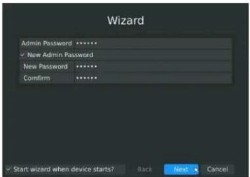
text_image
Wizard Admin Password ****** ✓ New Admin Password New Password ****** Confirm ****** ✓ Start wizard when device starts? Back Next CancelF-3.1.1
Note:
For the safety of your equipment, please change the initial password.
Step2. Date and time setting
Select the Time Zone and date via NTP or you can set date and time manually.
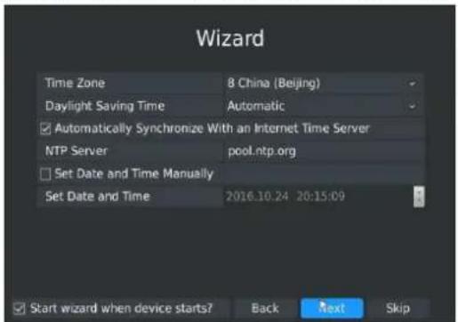
text_image
Wizard Time Zone 8 China (Beijing) Daylight Saving Time Automatic ✓ Automatically Synchronize With an Internet Time Server NTP Server pool.ntp.org □ Set Date and Time Manually Set Date and Time 2016.10.24 20:15:09 Start wizard when device starts? Back Next SkipF-3.1.2
Step3. Network setting
Input the IP Address, Subnet Mask, Gate Way and Preferred DNS Server. Internal NIC IPv4 Address option is only for PoE NVR.
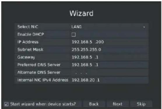
text_image
Wizard Select NIC LAN1 Enable DHCP IP Address 192.168.5 .200 Subnet Mask 255.255.255.0 Gateway 192.168.5 .1 Preferred DNS Server 192.168.5 .1 Alternate DNS Server ... Internal NIC IPv4 Address 192.168.20 .1 Start wizard when device starts? Back Next SkipF-3.1.3
Step4. Disk Management
Automatically detect the hard disk installed in NVR, and it supports formatting hard disk. You can create RAID in this page as well. (RAID is only supported on 7000-UH series, 7000-UPT series and 8000-UH series)
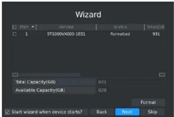
text_image
Wizard Port Vendor Status Total(GB) 1 ST1000VX000-1ES1 Formatted 931 Total Capacity(GB) 931 Available Capacity(GB) 929 Format Start wizard when device starts? Back Next SkipF-3.1.4
RAID will be available after after it was enabled and the device rebooted.
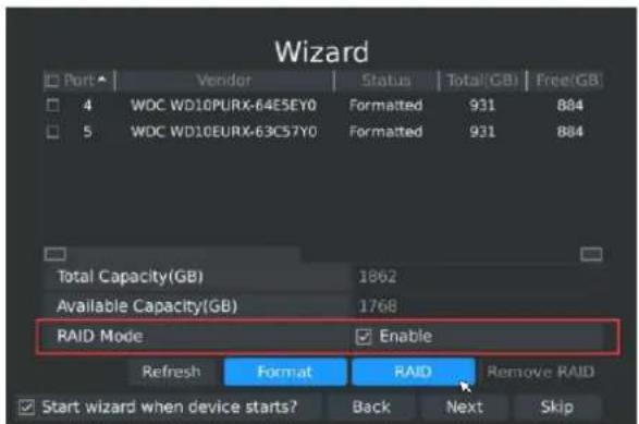
text_image
Wizard Port ▲ Vendor Status Total(GB) Free(GB) 4 WDC WD10PURX-64E5EY0 Formatted 931 884 5 WDC WD10EURX-63C57Y0 Formatted 931 884 Total Capacity(GB) 1862 Available Capacity(GB) 1768 RAID Mode Enable Refresh Format RAID Remove RAID Start wizard when device starts? Back Next SkipF-3.1.5
Step5. Camera Management
You can search all the cameras in LAN and select cameras to add to NVR. It can detect cameras that connected to PoE ports(only for PoE NVR).
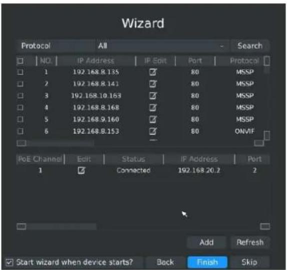
text_image
Wizard Protocol All Search NO IP Address IP Edit Port Protocol 1 192.168.8.135 ✓ 80 MSSP 2 192.168.8.141 ✓ 80 MSSP 3 192.168.10.163 ✓ 80 MSSP 4 192.168.8.168 ✓ 80 MSSP 5 192.168.9.160 ✓ 80 MSSP 6 192.168.8.153 ✓ 80_ONVIF PoE Channel Edit Status IP Address Port 1 ✓ Connected 192.168 20.2 2 Add Refresh Start wizard when device starts? Back Finish SkipF-3.1.6
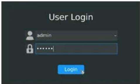
Step6. Login
Input the user name and password to login the system.
text_image
User Login admin LoginF-3.1.7
3.2 Playback
To play and backup the recorded files.
3.2.1 Video Playback
It can support playback according to recorded time. Play recorded video files in specified time period; synchronous playback of multi-channel is supported.
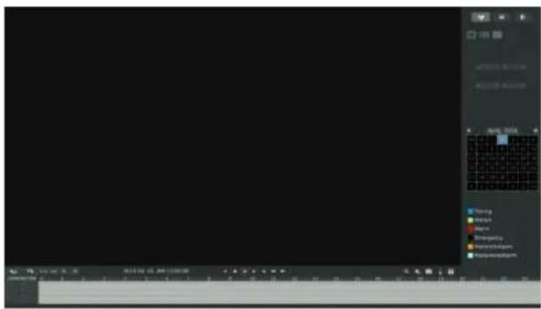
Step1. Click Main menu → Playback (F-3.2.1)
text_image
Screenshot of a software interface with a grid-based tool panel and toolbar, showing menu options like 'Temp', 'Balance', 'Short', etc.F-3.2.1
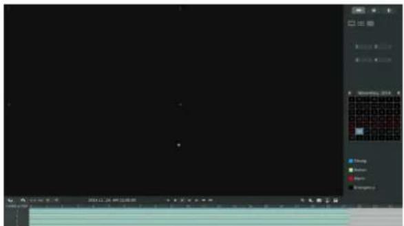
Step2. Select a desired channel and date
Select playback layout and channel. Click the date in red when there are recorded files of the selected channels, the record type with recording data will be shown as below, and then click
to playback.
text_image
Screenshot of a software interface with tool panels and a grid workspace, showing status bar and color options.F-3.2.2
Note:
- The day in blue has recording files; please select the date in blue to playback.
- Up to 16 channels can be selected to playback synchronously.
Video Playback Tool Bar Description

text_image
2014.11.28 AM (12:00:00)The tool bar can display multi-event record. It shows that in this record period what kind of event has happened. The symbolic meaning of each color is shown below:
Blue—Timing Green --- Motion
Red --- Alarm Black --- Emergency
And take the bar for example, it represents the motions and timing events that have been triggered in this period.
| Button | Description | Button | Description | Button | Description | Button | Description |
 | Rewind |  | Stop |  | Play |  | Pause |
 | Reverse Step |  | Forward Step | [STCG] | Fast Backward |  | Fast Forward |
 | Previous 4Cams |  | Next 4Cams |  | TimelineBackward |  | TimelineForward |
 | TimelineZoom In |  | TimelineZoom Out |  | Timeline |  | PlaybackPosition |
 | TimelineCutting |  | TimelineCut Off |  | Audio On |  | Audio Off |
 | Snapshot |  | Backup |
3.2.2 Video Files Backup
Regular recorded files can be backed up by various devices, such as USB flash drives (USB flash disk, USB HDD, USB writer), eSATA etc.
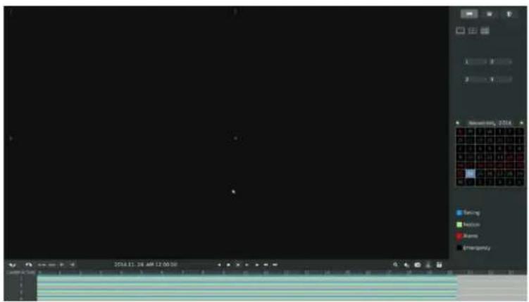
Step1. Click Main menu → Playback
text_image
2014.11.18 AM 12:00:50 Balance Balance Balance EmergencyF-3.2.3
Step2. Select Recorded files for Backup
Select the channel and date you want to backup, then select the start time at time line and click

it will change into which means cut begins.

text_image
2014.12.04, AM 4:42:17 CAMERA TIME 0 1 2 3 4 5 6 7 8 9 10 11 12 13 14 15 16 17 18 CutF-3.2.4
Select the end time at time line and click , it will change into ,which means cut ends.

text_image
2014.12.04, AM 6:47:00 CAMERATIME 0 1 2 3 4 5 6 7 8 9 10 11 12 13 14 15 16 17 18 19 1 2 3 4F-3.2.5
Step3. Click ,select Backup media and click [Backup].
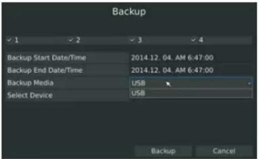
text_image
Backup ✓ 1 ✓ 2 ✓ 3 ✓ 4 Backup Start Date/Time 2014.12.04. AM 6:47:00 Backup End Date/Time 2014.12.04. AM 6:47:00 Backup Media USB Select Device USB Backup CancelF-3.2.6
Step4. The pop-up window will prompt: Please wait...
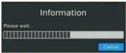
text_image
Information Please wait... CancelF-3.2.7
Step5. When all backup files have been exported, 'Backup Success' will be prompted.
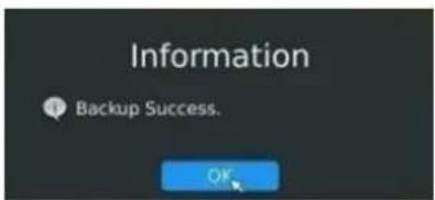
text_image
Information Backup Success. OKF-3.2.8
Note:
The file download time depends on the time of video you want to backup.
3.2.3 Picture Playback
Search and look for the snapshot files saved in HDD.
Step1. Click Main menu → Playback

Select a desired channel, start time and end time, click [Search]
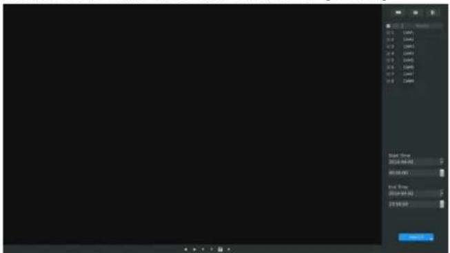
text_image
Start Time 2014-09-02 00:00:00 End Time 2014-09-02 23:00:00F-3.2.9
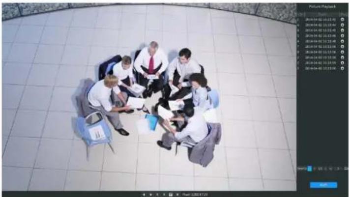
Step2. Enter Picture Info List and look up the pictures.
Click to play the desired pictures, or click to auto play the picture.
natural_image
Overhead view of a group of people in business attire gathered in a circle on a tiled floor, reviewing documents (no visible text or symbols)F-3.2.10
Picture Playback Tool Bar Description

| Button | Description | Button | Description | Button | Description | Button | Description |
 | Backward Play |  | Play |  | Previous Picture |  | Next Picture |
| Backup pictures | Close |
3.2.4 Picture Files Backup
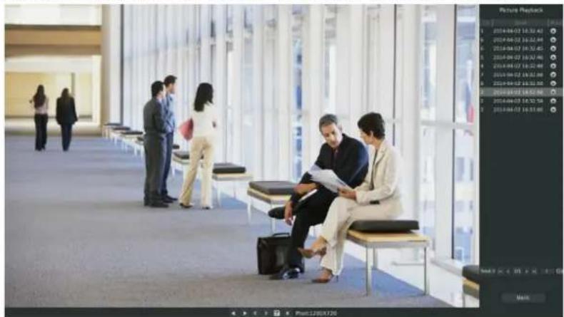
Step1. Select pictures you want to backup in picture playback interface.
text_image
Street photo with visible store signboards and people in business attire reviewing documents in a modern hallwayF-3.2.11
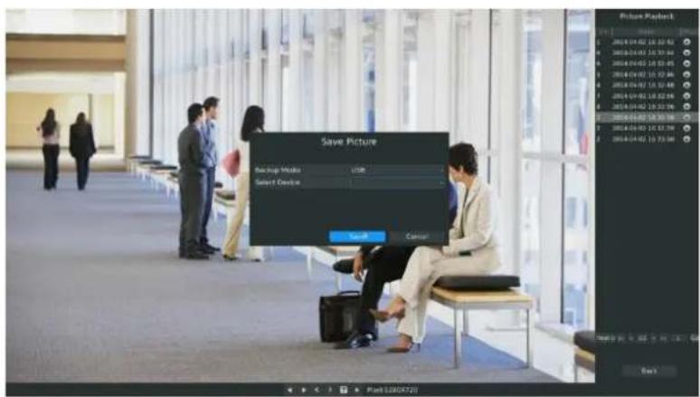
Step2. Select backup media and click to save picture.
text_image
Save Picture Backup Media USB Select Device Send Cancel File12805723 Picture Playset: 2016.04.02 19:32:43 2016.04.03 19:32:43 2016.04.03 19:32:43 2016.04.03 19:32:43 2016.04.03 19:32:43 2016.04.03 19:32:43 2016.04.04 19:32:43 2016.04.04 19:32:43 2016.04.04 19:32:43 2016.04.04 19:32:43 2016.04.04 19:32:43 2016.04.05 19:32:43 2016.04.05 19:32:43 2016.04.05 19:32:43 2016.04.05 19:32:43 2016.04.05 19:32:43 2016.04.06 19:32:43 2016.04.06 19:32:43 2016.04.06 19:32:43 2016.04.06 19:32:43 2016.04.06 19:32:43 2016.04.07 19:32:43 2016.04.07 19:32:43 2016.04.07 19:32:43 2016.04.07 19:32:43 2016.04.07 19:32:43 2016.04.08 19:32:43 2016.04.08 19:32:43 2016.04.08 19:32:43 2016.04.08 19:32:43 2016.04.08 19:32:43 2016.04.09 19:32:43 2016.04.09 19:32:43 2016.04.09 19:32:43 2016.04.10 19:32:43 2016.04.10 19:32:43 2016.04.11 19:32:43 2016.04.11 19:32:43 2016.04.12 19:32:43 2016.04.12 19:32:43 2016.04.13 19:32:43 2016.04.13 19:32:43 2016.04.14 19:32:43 2016.04.15 19:32:43 2016.04.15 19:32:43 2016.04.16 19:32:43 2016.04.17 19:32:43 2016.04.18 19:32:43 2016.04.19 19:32:43 2016.04.20 19:32:43 保存时间:无时间(以“+”为准) 保存方式:自动保存F-3.2.12
3.3 Camera Settings
Before configuration, please ensure that the camera is connected to the same network as your NVR and that the network setting for your NVR is properly setup.
3.3.1 Camera Management
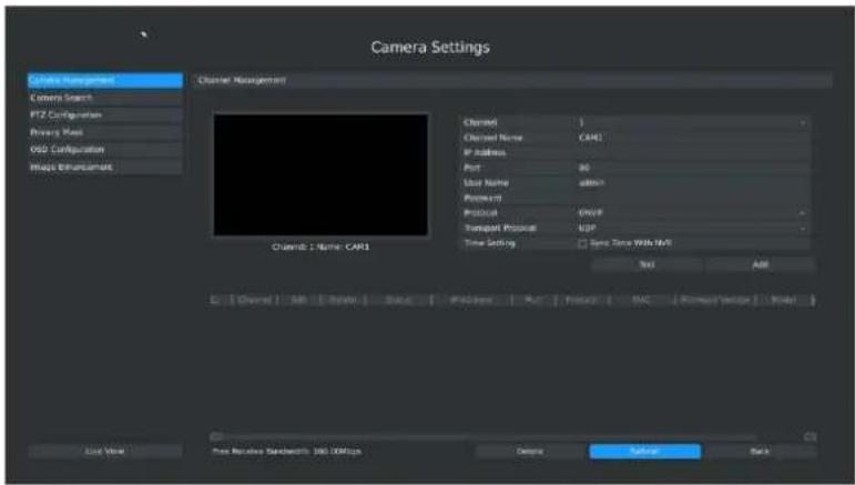
Step1. Click Main Menu → Camera → Camera Management
text_image
Camera Settings Channel Management Camera Search PTZ Configuration Binary Mask OGD Configuration Image Enhancement Channel Management Channel 1 Name: CAM1 Channel 2 Channel Name: CAM1 IP Address: Port: 80 User Name: admin1 Password: Protocol: ON/P Transport Protocol: UDP Time Setting: Same Time With NMI Text: Add Load View Free Received Sensitive: 100 MHz Delete Return BackF-3.3.1
Step2. Add IP Channel
Method1. Add IP Channel in device search interface
- Click Main Men→Camera → Device Search.
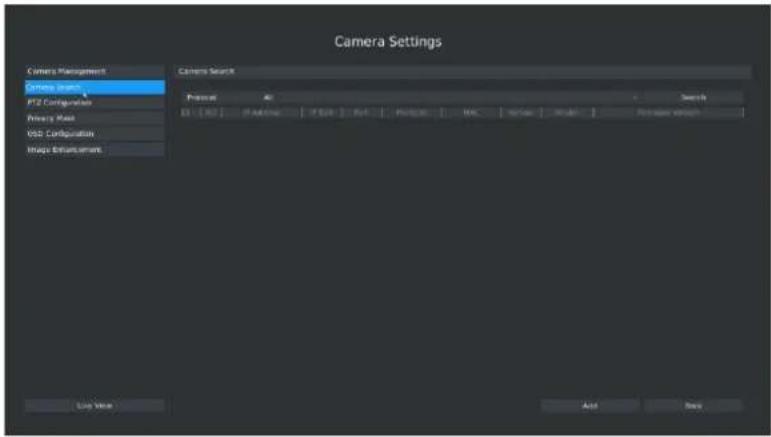
text_image
Camera Settings Camera Management Camera Search PTZ Configuration Primary Mass VSD Configuration Image Enhancement Camera Search Preview No. Search 01: 0.00 0.00 0.00 0.00 0.00 0.00 0.00 0.00 0.00 0.00 0.00 0.00 0.00 0.00 0.00 0.00 0.00 0.00 0.00 0.00 0.00F-3.3.2
- Click [search] button to quickly search the IP devices in LAN with different types: All, ONVIF, MSSP.
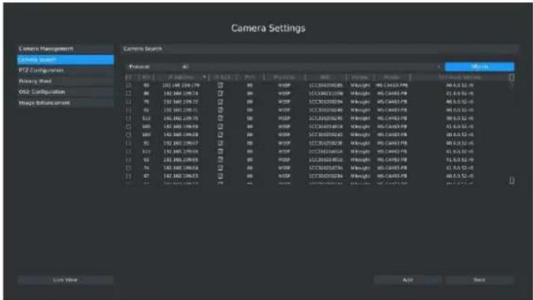
text_image
Camera Settings Camera Management Setting Camera PTZ Configuration Primary Mask OSU Configuration Image Enhancement Camera Search Photo File Edit View Tools Help Print Print Print Print Print Print Print Print Print Print Print Print Print Print Print Print Print Print Print Print Print Print Print Print Print Print Print Print Print Print Print Print Print Print Print Print Print Print Print Print Print Print Print Print Print Print Print Print Print Print Print Print Print Print Print Print Print Print Print Print Print Print Print Print Print Print Print Print Print Print Print Print Print Print Print Print Print Print Print Print Print Print Print Print Print Print Print Print Print Print Print Print Print Print Print Print Print Print Print Print Train View: 100 Auto: 100 Auto: 100 Auto: 100 Auto: 100 Auto: 100 Auto: 100 Auto: 100 Auto: 100 Auto: 100 Auto: 100 Auto: 100 Auto: 100 Auto: 100 Auto: 100 Auto: Auto: 100 Auto: 100 Auto: 100 Auto: 100 Auto: 100 Auto: 100 Auto: 100 Auto: 100 Auto: 100 Auto: 100 Auto: 100 Auto: 100 Auto: 100 Auto: 100 Auto : Auto : Auto : Auto : Auto : Auto : Auto : Auto : Auto : Auto : Auto : Auto : Auto : Auto : Auto : Auto : Auto : Auto : Auto : Auto : Auto : Auto : Auto : Auto : Auto : Auto : Auto : Auto : Auto : Auto : Auto : Auto : Auto : Auto : Auto : Auto : Auto : Auto : Auto : Auto : Auto : Auto : Auto : Auto : Auto : Auto : Auto : Auto : Auto : Auto : Auto : AUTO / AUTO / AUTO / AUTO / AUTO / AUTO / AUTO / AUTO / AUTO / AUTO / AUTO / AUTO / AUTO / AUTO / AUTO / AUTO / AUTO / AUTO / AUTO / AUTO / AUTO / AUTO / AUTO / AUTO / AUTO / AUTO / AUTO / AUTO / AUTO / AUTO / AUTO / AUTO / AUTO / AUTO / AUTO / AUTO / AUTO / AUTO / AUTO / AUTO / AUTO / AUTO / AUTO / AUTO / AUTO / AUTO / AUTO / AUTO / AUTO / AUTO / AUTO | NoneF-3.3.3
- Double click the channel, input password and click [Add] button.
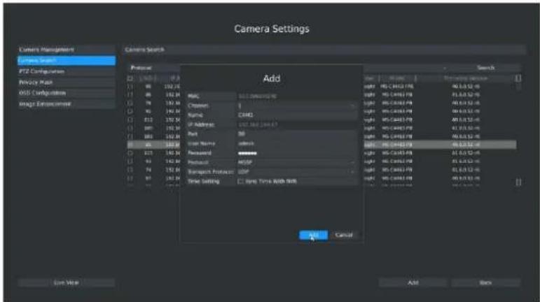
text_image
Camera Settings Camera Management Camera Search PTZ Configurations Privacy Maps USB Configuration Image Environment Add Cancel Add Cancel Add Cancel Add Cancel Add Cancel Add Cancel Add Cancel Add Cancel Add Cancel Add Cancel Add Cancel Add Cancel Add Cancel Add Cancel Add Cancel Add Cancel Add Cancel Add Cancel Add Cancel Add Cancel Add Cancel Add Cancel Add Cancel Add Cancel Add Cancel Add Clear View Add BackF-3.3.4
Or you can bulk adding the network cameras If they are with the same password, and you can choose TCP or UDP transport protocol for bulk adding. Click [OK] to finish bulk adding.
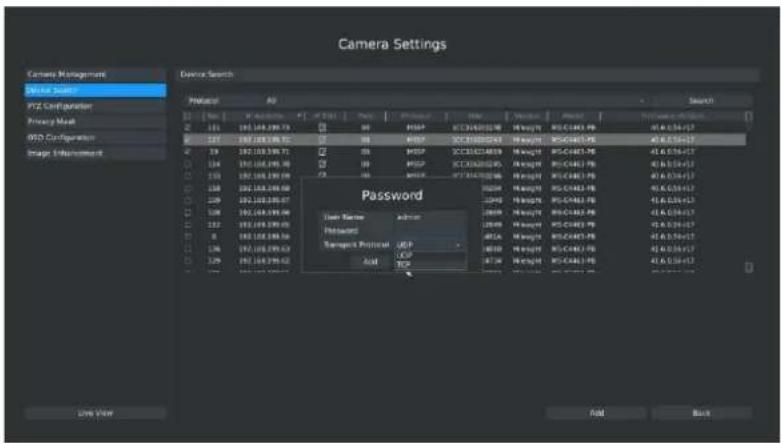
text_image
Camera Settings Device Search Password User Name: admin Password Remove Protocol: UDP Add TCPF-3.3.5
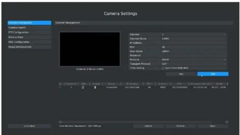
Method2. Add IP Channel in camera management interface
- Click Main Men→Camera → Camera Management
text_image
Camera Settings Camera Management Camera Search PTZ Components Primary class OSU Configuration Image Enhancement Channel Management Channel 3 Name: CAMS Channel 2 Channel Name: CAMS IP Address Port: ISO User Name: HTTP Physical Project: DRIVE Tangout Protocol: LGP Time Setting: Spot Time With OK Temp: Add Load Value Free Receive Scode: 100 MHz 确定 Refresh BackF-3.3.6
- Select idle channel then input complete information, click [Add] button.
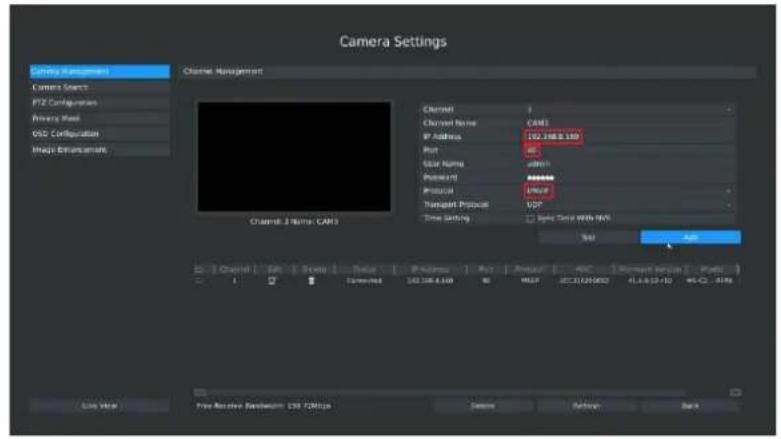
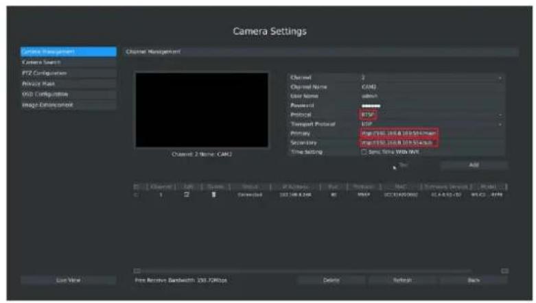
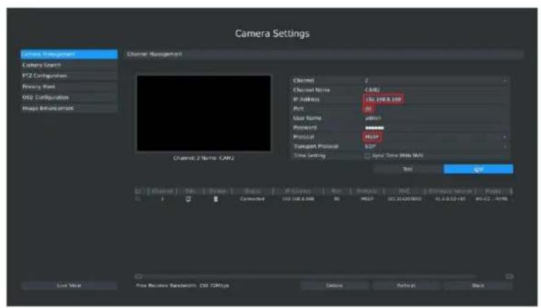
There are three protocols available for camera connection:
- ONVIF: You can add any IP cameras with ONVIF protocols if you selected this protocol. Details are shown in F-3.3.7;
- RTSP: You can add any IP cameras with RTSP protocol streams (Port: 554). You need to input complete resource path of the IP camera to add it. Take Milesight device for example, the resource path of main stream is "rtsp://IP:port/main" and of second stream is "rtsp://IP:port/sub". Details are shown in F-3.3.8;
- MSSP: You can add Milesight cameras which are in the same LAN by select this protocol. Details are shown in F-3.3.9;
text_image
Camera Settings Camera Management Camera Start PTZ Configuration Primary Mail USD Configuration Image Extensions Channel Management Channel 3 Name: CAM1 Channel Name: CAM1 IP Address: 192.108.159 Port: 46 Gular Name: admin Protocol: ******** Transport Protocol: UDP Time Setting: 12 sec Time With MSV Set Add Gray Edit Scale Value Position Port Preview AFC Software Version Paste C:\Users\Pre-Receiver Framework\129\CMYps Close View Cancel Refresh BackF-3.3.7 ONVIF
text_image
Camera Settings Camera Management Camera Search PTZ Configuration Private Host VSD Configuration Image Connection Channel Management Channel 2 Name: CAMJ Channel 3 Channel Name: CAMJ User Name: admin Protocol: Protocol: Transport Protocol: Primary: Secondary: Time SETTING: Temp, Time & Web: None Add Load View Pre-Receive Bandwidth: 100% FOMbps Delete Refresh BackF-3.3.8 RTSP
text_image
Camera Settings Camera Management Camera Search PTZ Configuration Primary Mask USB Configuration Impact Detection Channel Management Channel 2 Name: CAM2 Channel 2 Channel Name: CAM2 IP Address: 152.108.199 Port: 0 User Name: 40000 Protocol: ****** Protocol: 10000 Transport Protocol: 100 Time setting: Spot Time With SIM Temp OK Cancel Free Receiver Feedback: CMY-TCOMY Delete Refresh BackF-3.3.9 MSSP
Step3. Check the connection status
After adding the IP channels, click [Refresh] button, then [connected] appears under[status]. If it doesn't appear, you need to check if the network is connected or whether the user name, password is correct or not.
| □ | Channel | Edit | Delete | Status | IP Address | Port | Protocol | MAC | Firmware Version | Model |
| □ | 1 | ☑ | ☐ | Connected | 192.168.8.168 | 80 | MSSP | 1CC316200092 | 41.6.0.52-r10 | MS-C2...RFPB |
| □ | 2 | ☑ | ☐ | Connected | 192.168.8.167 | 80 | MSSP | 1CC31621038E | 40.6.0.52-r10 | MS-C4473-PB |
| □ | 3 | ☑ | ☐ | Connected | 192.168.8.163 | 80 | MSSP | 1CC316200098 | 41.6.1.52-r6 | OEM-C3762 |
| □ | 4 | ☑ | ☐ | Connected | 192.168.8.141 | 80 | MSSP | 1CC316210022 | 40.6.0.52 | MS-C2962-FIPB |
| □ | 6 | ☑ | ☐ | Connected | 192.168.8.132 | 80 | MSSP | 1CC3162000A5 | 41.6.0.52-r7 | MS-C2...RFIPB |
F-3.3.10
Step4. Configure IP Channel
- After successfully adding the channel, click or double-click this channel to re-edit the channel info, address, and password, etc.
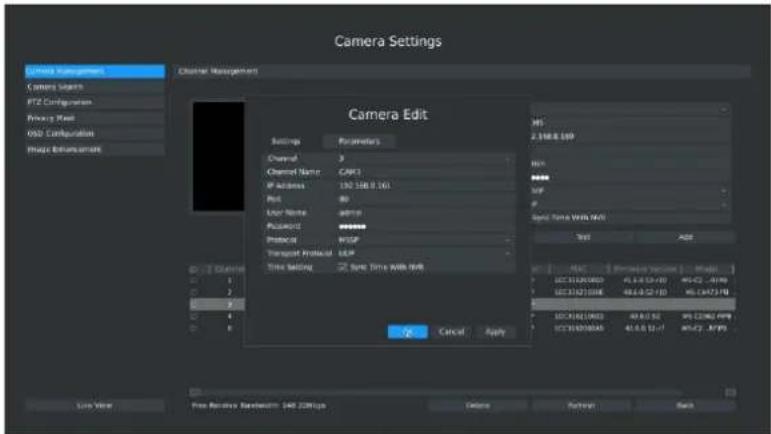
text_image
Camera Settings Camera Management Camera Search PTZ Configuration Proxy Mesh OSO Configuration Image Environment Channel Management Camera Edit Settings Parameters Channel 3 Channel Name:CAM1 IP Address: 190 548.0.161 Port 80 User Name:dsnr Password:**** Protocol: Transport Protocol:LSP Time Setting Sync Time with IWP OK Cancel Apply Test Add LAN HLS 2.548.8 LSP HLS HLS SFP SFP Sync Time With NWS Text Add LAN HLS 2.548.8 LSP HLS HLS SFP SFP SFP SFP SFP SFP SFP SFP SFP SFP SFP SFP SFP SFP SFP SFP SFP SFP SFP SFP SFP SFP SFP SFP SFP SFP SFP SFP SFP SFP SFP SFP SFP SFPF-3.3.11
Note:
By default, the user name and password entered here are the default user name and password. The management port is 80 and the default Transport protocol is UDP.
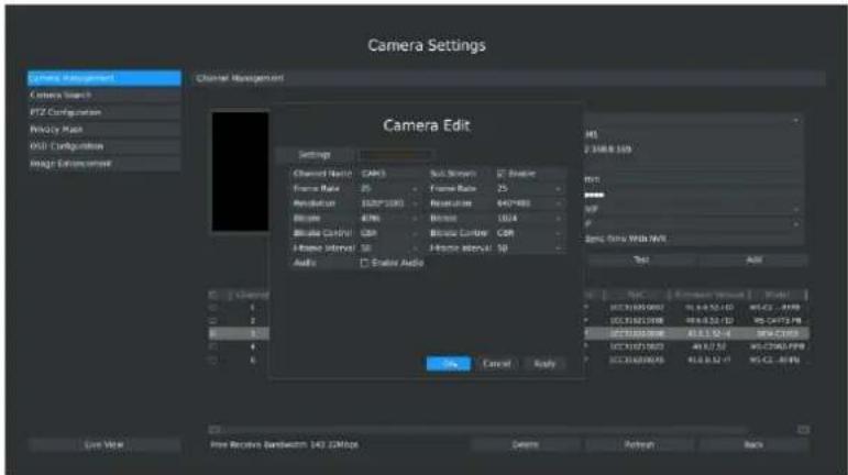
- Select [Parameters] attribute page to re-edit this channel parameters. Click [Save] to save the configuration
text_image
Camera Settings Channel Management Camera Search PTZ Configuration Poly Type Mode USB Configuration Resign Environment Camera Edit Settings Channel Name: CAMS Sub-System: 25 Frame Rate: 25 Amplifier: 1027*1000 Amplifier: 400 Blotting: 100 Blotting Control: GB Blotting Control: GB J-Home Interval: 50 J-Home Interval: 50 Audio: Enable Audio OK Cancel Apply File Edit View Insert Tools Help USB:136280000 91.6.9.12-1D WDCL - .4M USB:136280000 91.6.9.12-1D WDCL-4M USB:136280000 91.6.9.12-1D WDCL-4M USB:136280000 91.6.9.12-1D WDCL-4M USB:136280000 91.6.9.12-1D WDCL-4M Auto Input Select Screen: 143.32Mbps Down BackF-3.3.12
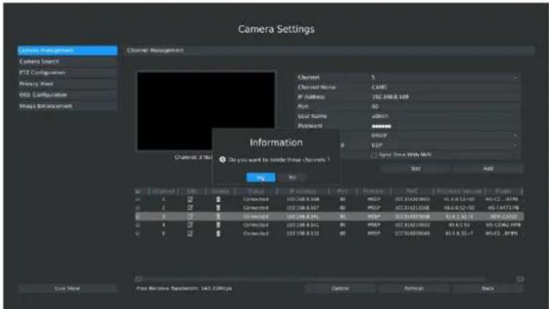
- You can delete this IP channel by clicking, or you can multi-select the devices and then
Delete click to delete(PoE channel does not support deleting).
| ☐ | Channel | Edit | Delete | Status | IP Address | Port | Protocol | MAC | Firmware Version | Model |
| ☐ | 1 | ☑ | ☐ | Connected | 192.168.8.168 | 80 | MSSP | 1CC316200092 | 41.6.0.52-r10 | MS-C2...RFPB |
| ☐ | 2 | ☑ | ☐ | Connected | 192.168.8.167 | 80 | MSSP | 1CC31621038E | 40.6.0.52-r10 | MS-C4473-PB |
| ☐ | 3 | ☑ | ☐ | Connected | 192.168.8.163 | 80 | MSSP | 1CC316200098 | 41.6.1.52-r6 | OEM-C3762 |
| ☐ | 4 | ☑ | ☐ | Connected | 192.168.8.141 | 80 | MSSP | 1CC316210022 | 40.6.0.52 | MS-C2962-FIPB |
| ☐ | 6 | ☑ | ☐ | Connected | 192.168.8.132 | 80 | MSSP | 1CC3162000A5 | 41.6.0.52-r7 | MS-C2...RFIPB |
text_image
Camera Settings Channel: 100000000000000000000000000000000000000000000000000000000000000000000000000000000000000000000000000 Channel: 3 Channel Name: CAMS IP Address: 182.398.8.169 Port: 85 User Name: admin Password: ****** USB: 149 Signal: Yes/Yes/Yes/Yes/Yes/Yes/Yes/Yes/Yes/Yes/Yes/Yes/Yes/Yes/Yes/Yes/Yes/Yes/Yes/Yes/Yes/Yes/Yes/Yes/Yes/Yes/Yes/Yes/Yes/Yes/Yes/Yes/Yes/Yes/Yes/Yes/Yes/Yes/Yes/Yes/Yes/Yes/Yes/Yes/Yes/Yes/Yes/Yes/Yes/Yes/Yes/No Channel: 2.16e-1 Do you want to include these channels: Test Add Source: Time Web Mail OK Cancel Load Value Free Receive Timestamp: 343.22MHz Delete Refresh BackF-3.3.13
Step5. Configure PoE Channel(Only for PoE NVR)
- Connect camera to PoE port, it will detect the camera automatically.
- If the camera's password is "ms1234", it will authenticate successfully and change the camera into the same network segment with internal NIC IPv4 address, then the camera will be connected successfully.
- If the camera's password is not "ms1234", it will show disconnected status in the PoE channel.
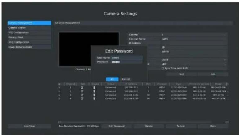
You need to input the camera's password by clicking to realize
authentication ( you can also multi-select the devices and then click this button to modify). Then it will change the camera into the same network segment with internal NIC IPv4 address and the camera will be connected successfully. In next time, NVR will use the password you input to authenticate this camera when you re-plug it.
text_image
Camera Settings Camera Management Camera Search PTZ Configuration Binary Back OSD Configuration Image Enhancement Channel Management Channel 1 Channel Name: CAMS By Address: BD Admin Edit Password User Name: admin- Password: ****** Cancel OK Cancel Cancel Cancel Cancel Cancel Cancel Cancel Cancel Cancel Cancel Cancel Cancel Cancel Cancel Cancel Cancel Cancel Cancel Cancel Cancel Cancel Cancel Cancel Cancel Cancel Cancel Cancel Cancel Cancel Cancel Cancel Cancel Cancel Cancel Cancel Cancel Cancel Cancel Cancel Cancel Cancel Cancel Cancel Cancel Cancel Cancel Cancel Cancel Cancel Cancel Cancal Time (Min: 80s) Test... Add... Last Value: Text Receive Bandwidth: 72.5GHz Edit: Password: Delete: Refresh: BackF-3.3.14
3.3.2 Device Search
You can search and add IP cameras here
Step1. Click Main men→ Camera → Device Search
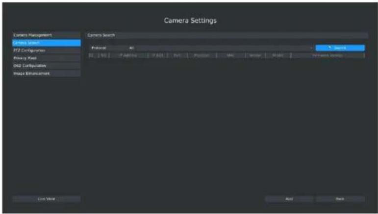
text_image
Camera Settings Camera Management Camera Search PIZ Configuration Proxy Maps Obl2 Configuration Image Enhancement Camera Search Profile: 0% Size: 100 px Add: 5x Remove: 5x Search Add: 5x Add: 5x Add: 5x Add: 5x Add: 5x Add: 5x Add: 5x Add: 5x Add: 5x Add: 5x Add: 5x Add: 5x Add: 5x Add: 5x Add: 5x Add: 5x Add: 5x Add: NoneF-3.3.15
Step2. Click [search] to quickly search the IP devices in LAN, you can choose different type to search: All, ONVIF, MSSP.
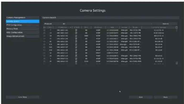
text_image
Camera Settings Camera Management System search PTZ Configuration Primary Mask VSD2 Configuration Image Encumbrance Camera Search Search Form 10 PTZ 10000000000000000000000000000000000000000000000000000000000000000000000000000000000000000000000 □ 7 □ 8 □ 9 □ 10 □ 11 □ 12 □ 13 □ 14 □ 15 □ 16 □ 17 □ 18 □ 19 □ 20 □ 21 □ 22 □ 23 □ 24 □ 25 □ 26 □ 27 □ 28 □ 29 □ 30 □ 31 □ 32 □ 33 □ 34 □ 35 □ 36 □ 37 □ 38 □ 39 □ 40 □ 41 □ 42 □ 43 □ 44 □ 45 □ 46 □ 47 □ 48 □ 49 □ 50 □ 51 □ 52 □ 53 □ 54 □ 55 □ 56 □ 57 □ 58 □ 59 □ 60 □ 61 □ 62 □ 63 □ 64 □ 65 □ 66 □ 67 □ 68 □ 69 □ 70 □ 71 □ 72 □ 73 □ 74 □ 75 □ 76 □ 77 □ 78 □ 79 □ 80 □ 81 □ 82 □ 83 □ 84 □ 85 □ 86 □ 87 □ 88 □ 89 □ 90 □ 91 □ 92 □ 93 □ 94 □ 95 □ 96 □ 97 □ 98 □ 99 □100F-3.3.16
- ONVIF: Search the cameras that support ONVIF protocol and in the same network segment with NVR.
● MSSP: Search the Milesight cameras in LAN even with different network segments.
3.3.3 PTZ Configuration
3.3.3.1 PTZ control Parameters Configuration
Click Main Menu→ Camera → PTZ Configuration, select "Configuration" page. Choose a channel and set the PTZ parameters. Besides you can click [Copy] to copy the same configuration to other channels.
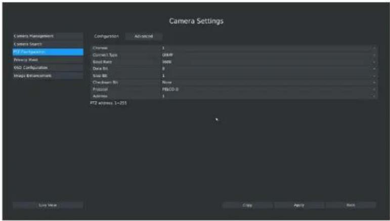
text_image
Camera Settings Camera Management Camera Search PTZ Configuration Primary Mail VSD Configuration Unique Environment Configuration Advanced Channels 1 Control Type QMP Signal Range WBI Data Bit 8 Stop Bit 1 Check Down Bit None Physical PBOD-B Address 1 PTZ address: 1-201 Last View Copy Apply BackF-3.3.17
Note:
- Settings for a PTZ camera must be configured before it can be used. Make sure that the PTZ and RS-485 of the NVR are connected properly.
- The PTZ protocol and address of IP channel must be consistent with those of the PTZ decoder.
3.3.3.2 Advanced Configuration
Main Menu → Camera → PTZ Configuration, select "Advanced" page. There are two patrol ways can be set: Pattern and Path.
Note:
- IP channel does not support configuration and calling of presets, patrols and patterns.
- The functioning of presets patrols and patterns need front PTZ decoder to support.
1. Presets Point Setup
Preset can be set to move your PTZ camera to a desired preset location. The preset point is the preparation for Tour Patrol.
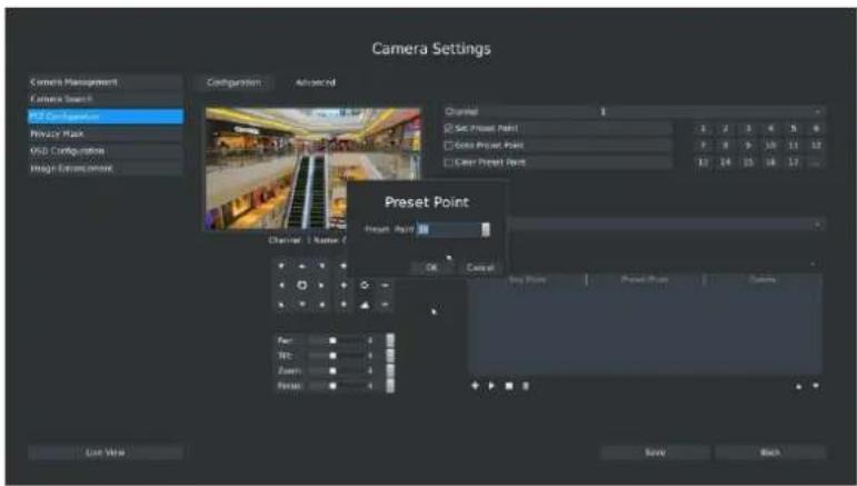
Step1. Use the PTZ direction key to rotate the position of preset. Then select "Set Preset Point" and select a preset number to finish a preset point setting. Repeat above steps to set more preset points.
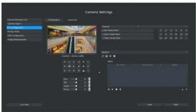
text_image
Camera Settings Camera Management Camera Search All Components Accuracy Mesh All Components Map Enhancement Configuration selected Clutter: 100% (CAM) Clutter: 100% (CAM) Clutter: Set Press Part Set Press Part Clear-Reset Mock Clutter: Set Press Part Set Press Part Clear-Reset Mock Clutter: Set Press Part Set Press Part Clear-Reset Mock Clutter: Set Press Part Set Press Part Clear-Reset Mock Clutter: Set Press Part Set Press Part Clear-Reset Mock Clutter: Set Press Part Set Press Part Clear-Reset Mock Clutter: Set Press Part Set Press Part Clear-Reset Mock Clutter: SET Press Part Set Press Part Clear-Reset Mock Clutter: Set Press Part Set Press Part Clear-Reset Mock Clutter: Set Press Part Set Press Part Clear-Reset Mock Clutter: Set Press Part Set Press Part Clear-Reset Mock Clutter: Set Press Part Set Press Part Clear-Reset Mock Clutter: Set Press Part Set Press Part Clear-Reset Mock Clutter: Set Press Part Let View OK Cancel HelpF-3.3.18
Step2. Click to save or call more preset points after number 17.
text_image
Camera Settings Camera Management Camera Search HIT Configuration Privacy Mask OBS Configurations Image Extrations Configuration Advanced Channel 1 Set Preset Point Gaze Preset Point Clear Preset Point Preset Point Reset Point OK Cancel Play Place Preset Point Colors Play Play: Zoom: Finish Last View Back BackF-3.3.19
Step3. Select 'Clear Preset Point' and click a preset number to delete the preset point. Step4. Select "Goto Preset Point". Click a preset number to check the preset point.
2. Track Patrol
The camera will patrol according to the key points. The total time and patrol speed of the path is variable.
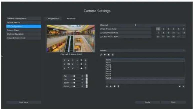
Step1. Select a path. Up to 8 paths could be set.
text_image
Camera Settings Camera Management Device Search MF Configener Resource Maps OSU Configuration Image Environment Configuration Advanced Channel 2 Set Preset Point Gate Preset Point Clear Preset Point 13:14:15:16:17: Channel 2 Name: CAM2 Input View Position Focus Apply Back Network1 Run01 Run02 Run03 Run04 Run05 Run06 Run07 Run08F-3.3.20
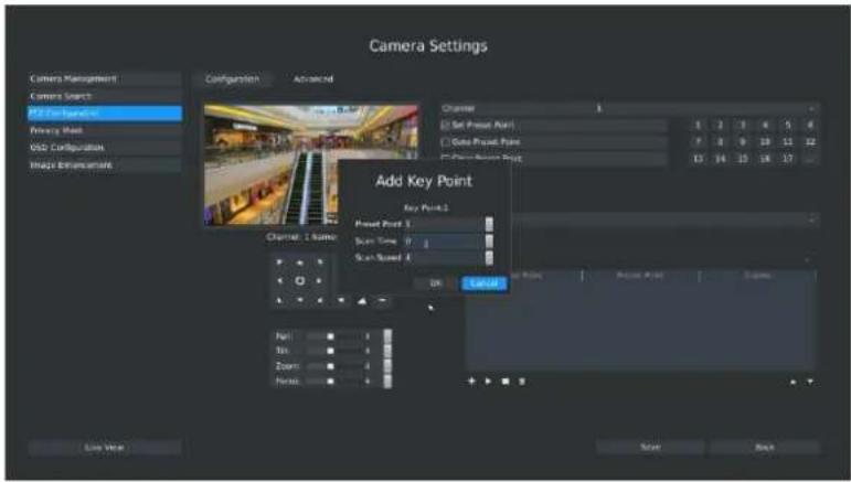
Step2. Click to add preset points which is up to 48. Set the preset point parameters (including preset point number, scan time and scan speed) and click [OK].
text_image
Camera Settings Camera Management Camera Search F2 Configuration Privacy Mesh GSD Configuration Impact Extensions Configuration Advanced Channel 1 [ Set Preset Point ] [ Data Preset Point ] [ Data Preset Target ] Add Key Point Key Point 1 Preset Point 3 Start Time 0 Start Speed 0 OK Cancel Load View Save BackF-3.3.21
Step3. Repeat the above steps to add more preset points to the Path patrol.
Step4. Select a preset point, select [Delete] and select [Yes] in the dialog box to delete it.
Step5. Click to preview the path patrol. Click to stop.
Step6. Click and select [Yes] in the dialog box to delete all key points of the path patrol.
Note:
- The preset point decides the patrol path, which will run according to numerical order of the preset points.
- Scan time is how long the patrol stays on the preset point.
- Scan speed is the rotate speed of speed dome from one preset point to the next.
3. Pattern
The camera will patrol back and forth in a constant speed. There is only one start point and one end point.
Step1. Select a pattern and click . Up to 4 patterns could be set.

text_image
Camera Settings Camera Management Device Search PTC Configuration Privacy Mask OISI Configuration Image Enhancement Configuration Advanced Channel 2 Set Preset Point Grid Preset Point Clear Preset Point 11 16 19 18 17 Pan: Size: Zoom: Focus Live Now Apply BackF-3.3.22
Step2. Drag the mouse or click 8 direction keys of mouse control field to rotate PTZ.
Step3. Click to save the PTZ movement patterns to the pattern.
Step4. Click to preview the pattern. Click to stop.
3.3.3.3 PTZ Control Operation
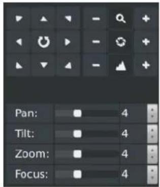
In live view mode, select quick menu of live view channel to enter PTZ control mode. It can access PTZ control by PTZ control bar or panel PTZ control button.
Description of PTZ Control Bar
text_image
Pan: 4 Tilt: 4 Zoom: 4 Focus: 4F-3.3.23
| Icon | Description | Icon | Description | Icon | Description |
 | PTZ Direction Control and Auto Scan Button |  | Adjust Zoom+, Focus+, IRIS+ |  | Adjust Zoom-,Focus-, IRIS- |
 | Zoom: Zoom in or out |  | Focus |  | IRIS |
 | Horizontal Movement Adjustment | ||||
 | Vertical Movement Adjustment | ||||
 | Zoom Adjustment | ||||
 | Focus Adjustment | ||||
3.3.4 Privacy Mask
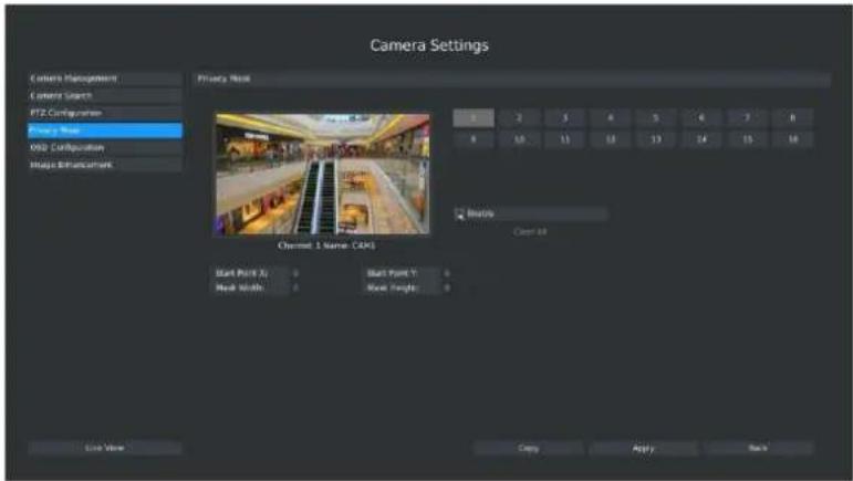
Milesight NVR support privacy mask. It is used to cover some privacy area which is not proper to appear on monitor.
Click Main Menu→ Camera → Privacy Mask.
text_image
Camera Settings Content Management Camera Search PTZ Configuration Energy Move KDD Configuration Logic Enhancement Private Work 8 2 3 4 5 6 7 8 4 10 11 12 13 14 15 16 Balance Cast All Channel 1 Name: CAX1 Start Point A: 0 Start Point Y: 0 Next Points: 0 Next Points: 0 Live View Copy Apply BackF-3.3.24
You can add a privacy mask by following steps:
Step1. Select channel on the right top of the interface, and enable it on the below of the channel;
Step2. Set the area of privacy mask:
Way1: Drag the mouse to select the area which is privacy on the live window;
Way2: Set the coordinates of privacy area in the columns below the live window;

text_image
Camera Settings Camera Management Camera Search PT2 Configuration Privacy Mask 092 Configuration Image Entanglement Privacy Mask 1 2 3 4 5 6 7 8 9 10 11 12 13 14 15 16 Channel 1 Name: CAX1 Start Point A Start Point Y Start Points Start Height Live View Copy Apply BackF-3.3.25
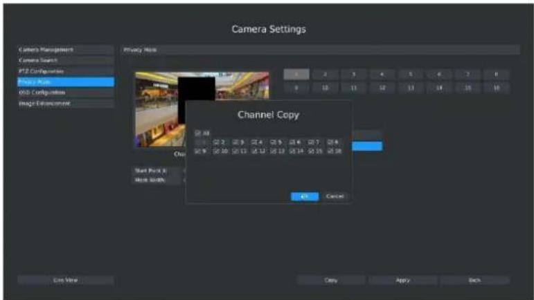
Step3. Copy the privacy area to the other channels by click the "copy" button on the bottom of the windows;
text_image
Camera Settings Camera Management Camera Search PTZ Configuration Image Mask WID Configuration Image Exchange Privacy Mask Channel Copy Start Pack 8 Move Width OK Cancel Live View Copy Apply BackF-3.3.26
Step4. Select "Apply" to save the settings.
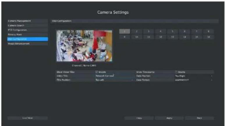
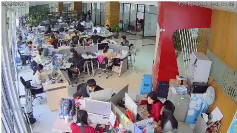
3.3.5 OSD configuration
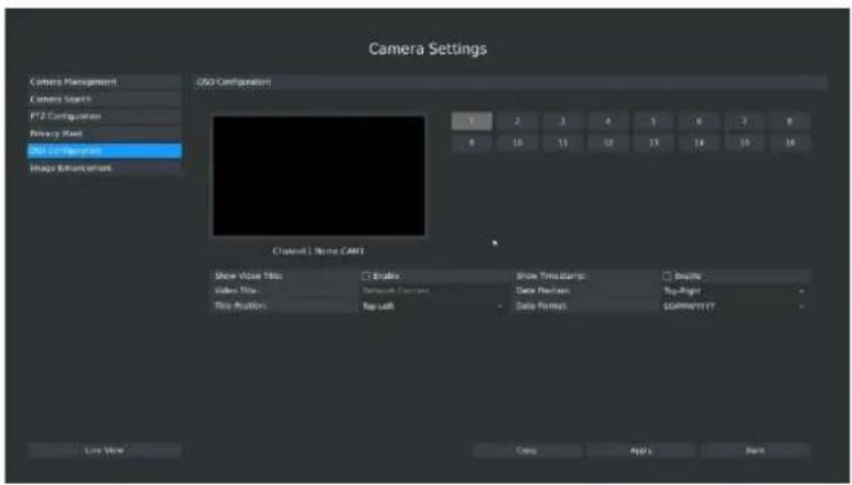
You can set OSD (On Screen Display) on NVR, and the OSD will be synchronized to Camera. Click Main Menu → Camera → OSD Configuration.
text_image
Camera Settings Camera Management Camera Search PTZ Errington Privacy Mask H50 Combinations Image Enhancement OSO Configuration 3 2 3 4 5 6 7 8 9 10 11 12 13 14 15 16 Channel 1 Name CAN1 Show Video Title □ Endo Show Time Clamp □ Short Video Title □ Network Camera Data Packets □ Top Right Play Position □ Top Left □ Data Format □ COMPRETANT Live View Apply HelpF-3.3.27
Step1. Select channel by clicking the channel number on the right-top, the selected channel will change into gray and the channel number will change into yellow;

Step2. Enable video title and timestamp:
| Show Video Title: | √ Enable | Show Timestamp: | √ Enable |
| Video Title: | Room1 | Date Position: | Bottom-Left |
| Title Position: | Top-Right | - Date Format: | MM/DD/YYYY |
[Video Title]: Set the video title for the channel;
[Title Position]: Set the position for the video title: Top-Left or Top-Right;
[Date Position]: Set the position for the date: Top-Left, Top-Right, Bottom-Left or Bottom-Right;
[Date Format]: Set format for date: YYYY-MM-DD, MM/DD/YY or DD/MM/YYYY;
text_image
Camera Settings Camera Management Camera Search PTZ Combinations Binary Maps OSG Configuration Maps Enhancement OSG Configuration 1 2 3 4 5 6 7 8 9 10 11 12 13 14 15 16 Channel 1 Name CAN1 Show View Title: ☑ Inside Video Title: Network Center Title Position: Top-left Show Timeframe: ☐ Blade Data Position: Top-Right Deep Format: COMWEETY Save View Copy Apply BackF-3.3.28
natural_image
Interior view of a modern open-plan office with employees at desks and computers (no visible text or signage)F-3.3.29
Step3. Select "Apply" to save the settings.
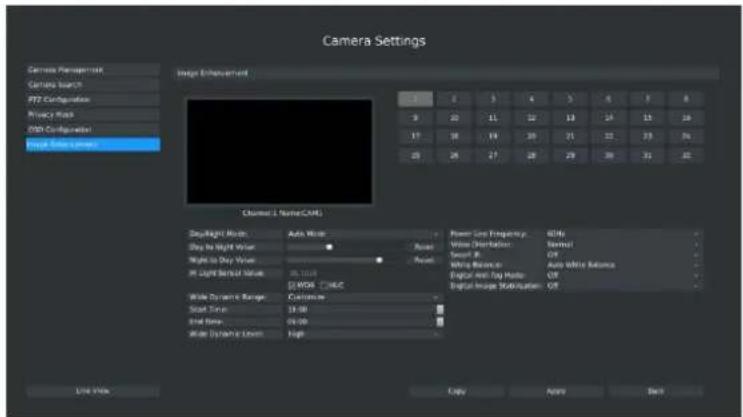
3.3.6 Image Enhancement
You can set Image Enhancement on NVR, and the configuration will be synchronized to Camera. Click Main Menu → Camera → Image Enhancement.
text_image
Camera Settings Camera Management Camera Search PTT Configuration Privacy Mask PSB Configuration Image Size Camera Image Enhancement Channel 1: Name/CAMS Background Mode: Auto Mode Stay in Night Value: Night to Day Value: 90 Light Signal Value: 25.104 [ ]WDS - [ ]MCC Wide Dynamic Range: Customize Sound Type: 3.00 End Time: 04:00 Wide Dynamic Level: High Power Line Frequency: Only Wire Distortion: Normal Signal A: Off Timing Before: Auto Delay Satons Digital Anti-Fay Mode: Off Digital Image Subtraction: Off Line Style Copy Apply BackF-3.3.30
Step1. Select channel by clicking the channel number on the right-top, the selected channel will change into gray and the channel number will change into yellow;
Step2. Set the configuration;
[Day/Night Mode]: Set the Day/Night mode for the channel;
[Day to Night Value]: Set the Minimum illumination intensity to trigger Night Mode;
[Night to Day Value]: Set the Maximum illumination intensity to trigger Day Mode;
[IR Light Sensor Value]: Shows the current value of IR light sensor;
[WDR/HLC]: Click to configure Wide Dynamic Range or High Light Control;
[Power Line Frequency]: 50Hz and 60Hz are available;
[Video Orientation]: Set the image rotation;
[Smart IR]: Set the Smart IR on and off;
[White Balance]: Choose a white balance mode for the channel;
[Digital Anti-fog Mode]: Set the Anti-fog function on and off;
[Digital Image Stabilisation]: Set the Image Stabilisation on and off.
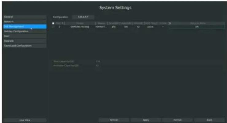
3.4 Record Settings
Preparation for Configuration
Step1. Ensure your NVR has installed and initialized the HDD.
Click System Settings → Disk Management
text_image
System Settings General Network Full Management Default Configuration Host Upgrade Save/Used Configuration Configuration E:\MAX Next > 1 Direct Network Direct Network AC/DC AC/DC AC/DC AC/DC AC/DC AC/DC AC/DC AC/DC AC/DC AC/DC AC/DC AC/DC AC/DC AC/DC AC/DC AC/DC AC/DC AC/DC AC/DC AC/DC AC/DC AC/DC AC/DC AC/DC AC/DC AC/PC AC/PC AC/PC AC/PC AC/PC AC/PC AC/PC AC/PC AC/PC AC/PC AC/PC AC/PC AC/PC AC/PC AC/PC AC/PC AC/PC AC/PC AC/PC AC/PC AC/PC AC/PC AC/PC AC/PC AC/PC AC/PCI AC/PCI AC/PCI AC/PCI AC/PCI AC/PCI AC/PCI AC/PCI AC/PCI AC/PCI AC/PCI AC/PCI AC/PCI AC/PCI AC/PCI AC/PCI AC/PCI AC/PCI AC/PCI AC/PCI AC/PCI AC/PCI AC/PCI AC/PCI AC/PCI AC/PC AC/PC AC/PC AC/PC AC/PC AC/PC AC/PC AC/PC AC/PC AC/PC AC/PC AC/PC AC/PC AC/PC AC/PC AC/PC AC/PC AC/PC AC/PC AC/PC AC/PC AC/PC AC/PC AC/PC AC/IPC AC/IPC AC/IPC AC/IPC AC/IPC AC/IPC AC/IPC AC/IPC AC/IPC AC/IPC AC/IPC AC/IPC AC/IPC AC/IPC AC/IPC AC/IPC AC/IPC AC/IPC AC/IPC AC/IPC AC/IPC AC/IPC AC/IPC AC/AI3A10000000000000000000000000000000000000000000000000000000000000000000000000000000000000000000000000000F-3.4.1
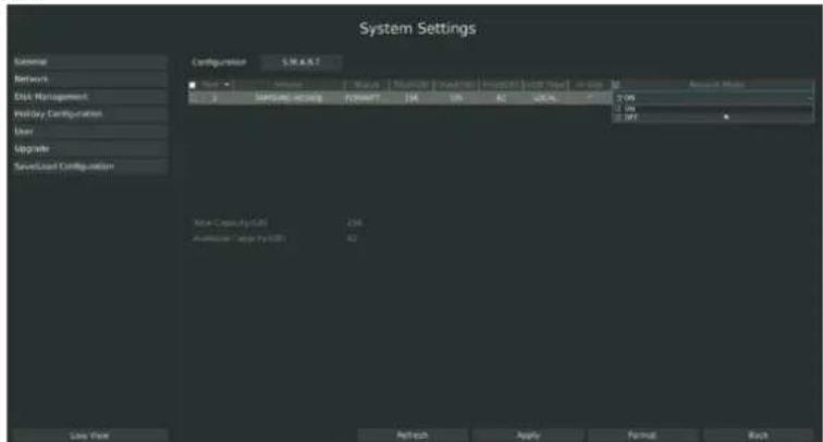
Step2. Ensure that the HDD has sufficient storage space.
Click System Setting → Disk Management. Select [Recycle Mode] to ON in the case of insufficient capacity of HDD.
text_image
System Settings External Network Disk Management Holiday Configuration User Upgrade Speed/Load Configuration Configuration: S.M.A.R.T Name: Sample Size Format: 100 100 62 LOCAL 2 ON 2 ON 3 OFF Note Capacity (GB) 256 Audience Type (USB) 50 List View Refresh Apply Format BackF-3.4.2
3.4.1 Record Mode
Step1. Click Main Men→ Record → Record Mode.
There are three record modes: No Recording/Always Record/Record by Schedule. You can select desired one to every channel.
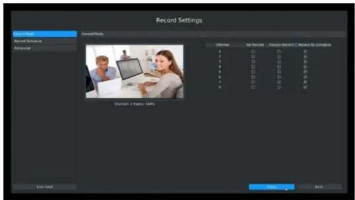
text_image
Record Settings Record Mode Record Schedule Advanced Record Mode Channel: 1st Record Channel 2 Names (CAM) Always Record Record by Schedule 1 2 3 4 5 6 7 8 9 10 11 12 13 14 15 16 17 18 19 20 21 22 23 24 25 26 27 28 29 30 31 32 33 34 35 36 37 38 39 40 41 42 43 44 45 46 47 48 49 50 51 52 53 54 55 56 57 58 59 60 61 62 63 64 65 66 67 68 69 70 71 72 73 74 75 76 77 78 79 80 81 82 83 84 85 86 87 88 89 90 91 92 93 94 95 96 97 98 99 100F-3.4.3
[No Record]: NVR will not record;
[Always Record]: NVR will always record the chosen channel;
[Record By Schedule]: NVR will record by schedule, details will be shown in 3.4.2;
Step2. Click [Apply] to save the configuration.
3.4.2 Record Schedule Setting
Note:
The days are divided as Holiday/Sunday/Monday/Tuesday/Wednesday/Thursday/Friday/
Saturday. The schedule of Holiday is superior to other days. To set the holiday information, go to Chapter 3.8.4.
Method1. General Setting
Step1. Click Record Settings → Record Schedule
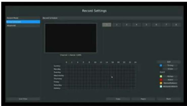
text_image
Record Settings Record Route Sunday Calendar Advanced Record Schedule Channel: 1 Name (CAFE) SUNTRY Monday Tuesday Wednesday Thursday Friday Saturday Sunday Monday Time Apply Back 0 2 4 6 8 10 12 14 16 18 20 22 24 SUN Timing Brown Fall 11 Normal Black Multi-Uniform Multi-Uniform Live View Time Apply BackF-3.4.4
Step2. Select desired channel (e.g. Channel 1) and click [Edit] button

text_image
Record Settings Record Mode Recovery Questionnaire Advanced Channel 1 Name: CARS Sunday Monday Tuesday Wednesday Thursday Friday Saturday Holiday End Timing Show Epicm Medium Alarm MotionCalciums MotionCalciums Long View Copy Apply BackF-3.4.5
Step3. Set record schedule
Select a day from the drop-down list of [Day], and select [Record Type] to setup the recording period, up to 12 periods can be set. (e.g.01:00 to 05:00 for none recording; 06:00 to 18:00 for timing recording; 19:00 to 21:00 for Motion recording; 22:00 to 24:00 for Alarm recording)
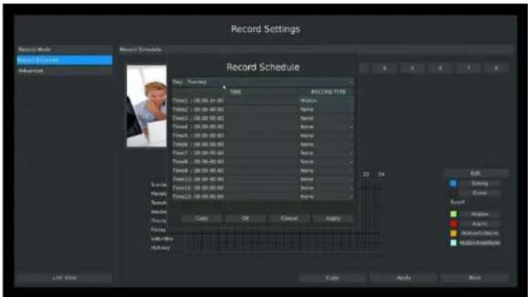
text_image
Record Settings Record Schedule Day: Tuesday Time Balance Time Time1: 00:00-01:00 Time2: 00:00-01:00 Time3: 00:00-01:00 Time4: 00:00-01:00 Time5: 00:00-01:00 Time6: 00:00-01:00 Time7: 00:00-01:00 Time8: 00:00-01:00 Time9: 00:00-01:00 Time10: 00:00-01:00 Time11: 00:00-01:00 Time12: 00:00-01:00 Copy OK Cancel Apply Edit Sitting Layer Event Motion Action Motion/Action Motion/Action Last Year Copy Apply ResetF-3.4.6
Note:
Time periods cannot overlap with each other.
Step4. Click [Copy] to copy settings to other weekdays, and then click [Apply] to confirm the setting.
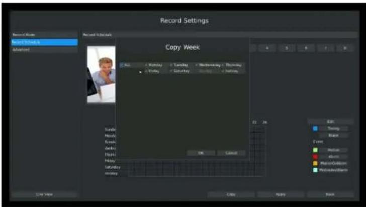
text_image
Record Settings Record Room Record Schedule Advanced Record Schedule Copy Week Copy Weekday Tuesday Wednesday Thursday Friday Saturday Sunday Monday 22 24 Edit Turning Blank Event Balance Abnormal BalanceButton BalanceButton OK Cancel Copy Apply BackF-3.4.7
Step5. Complete above steps, this channel will show as figure-3.4.8:
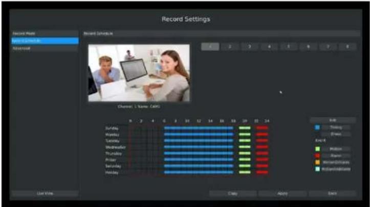
text_image
Record Settings Record Name Record Salvulink Channel 1 Name: CASH Date Time Green Exit Blue Red Yellow Orange Yellowish Green Magenta/Black Blue/Red/Orange Blue/Red/Black Gray Gray Gray Gray Gray Gray Gray Gray Gray Gray Gray Gray Gray Gray Gray Gray Gray Gray Gray Gray Gray Gray Gray Gray Gray Gray Gray Gray Gray Gray Gray Gray Gray Gray Gray Gray Gray Gray Gray Gray Gray Gray Gray Gray Gray Gray Gray Gray Gray Gray GreyF-3.4.8
Step6. Copy the recording settings to other channels
Select [Copy] to copy the same settings to other channels. And click [OK] to save the configuration.
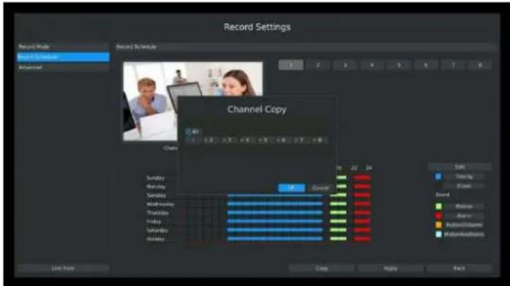
text_image
Record Settings Record Mode Record Schedule Advanced Channel Copy 10 22 24 Sunday Monday Tuesday Wednesday Thursday Friday Saturday Sunday Monday 6 22 24 Gencer 58 7 22 24 5 2 3 4 5 6 7 8 Start Time Copy Reply BackF-3.4.9
Step7. Save the configuration
Click [Apply] button to save the configuration, and then click [Back] to return to the previous menu.
Method2.Set record schedule by drag the mouse
Step1. Click Record Settings→ Record Schedule
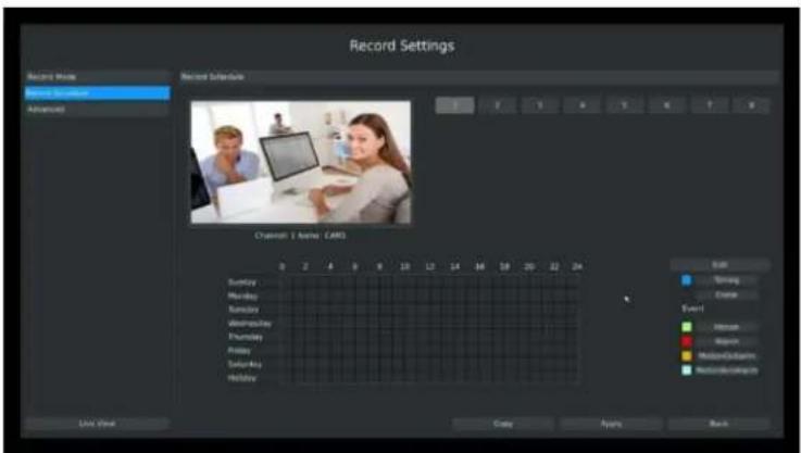
text_image
Record Settings Record Numbers Record Sequence Advanced Record Subsequence Channel 1 Active: CARES Start Warning Event Monday Monday Wednesday Thursday Friday Saturday Holiday Copy Apply BackF-3.4.10
Step2. Click desired channel and record type show as below:
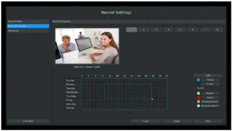
text_image
Record Settings Record Name Record Schedule Adjustor Channel: 1 Name: CAF2 0 3 4 5 6 8 10 12 14 16 18 20 22 24 Sunday Monday Tuesday Wednesday Thursday Friday Saturday Sunday MondayF-3.4.11
Step3. Drag the mouse to draw certain areas in recording setting zone and then click [Apply] to save the configuration.
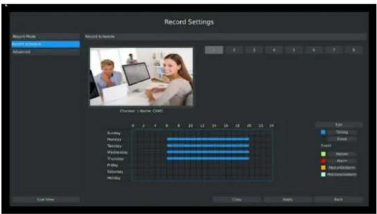
text_image
Record Settings Record Mode Record Schedule Record Date Channel 1 (Name: CAM) Sunday Monday Tuesday Wednesday Thursday Friday Saturday Sunday MondayF-3.4.12
Step4. Copy the recording settings to other channels.
Select [Copy] to copy the same settings to other channels. And click [OK] to save the configuration.
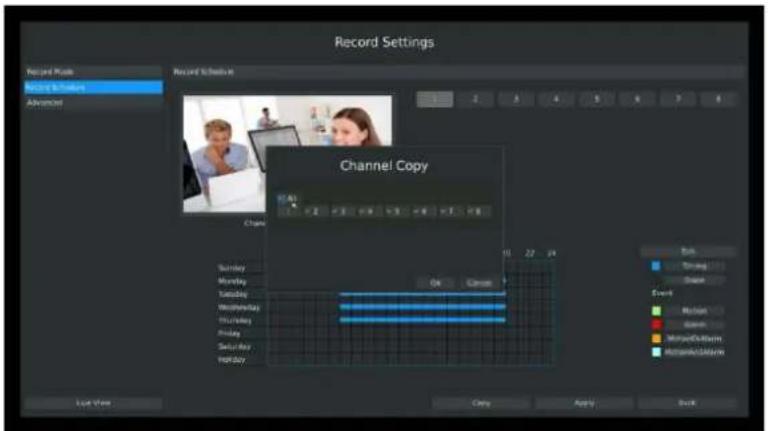
text_image
Record Settings Record Mode Record Settings Advanced Record Schedule Channel Copy Sunday Monday Tuesday Wednesday Thursday Friday Saturday Holiday OK Cancel 10 22 24 Back Timing Show Event Motion Gloss MatchSetIcon MatchSetIcon Last View Copy Apply BackF-3.4.13
3.4.3 Advanced settings
You can set the advanced settings there.
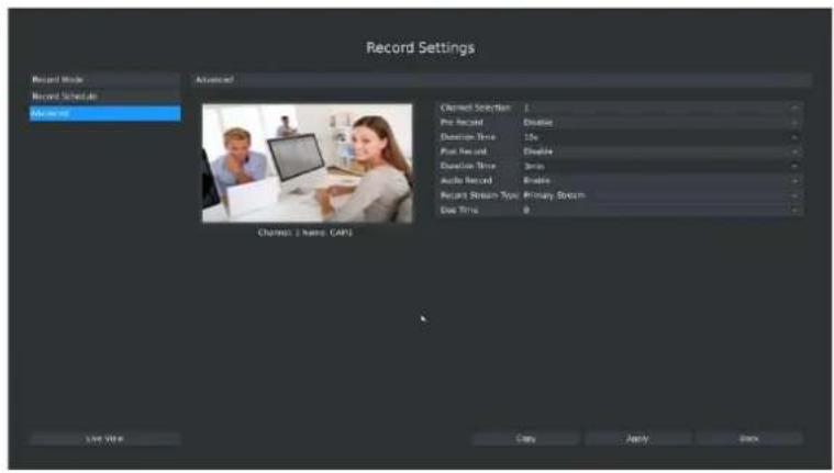
text_image
Record Settings Record Mode Record Schedule Recorded Advanced Channel Selection 1 Pre Record Duration Time 15s First Record Duration Time 3ms Audio Record Record Stream Type Primary Stream Dow Time 0 Channels: 2 Name: CAPS Use View Copy Apply BackF-3.4.14
[Channel Selection]: Select the channel which will be set.
[Pre Record]: Enable/Disable pre record before the event is triggered
[Duration Time]: Event pre-record duration time
[Post Record]: Enable/Disable post record after the event is over
[Duration Time]: Event post-record duration time
[Audio Record]: Select to record audio or not
[Record Stream Type]: Select Main stream or sub stream for record
[Due Time]: Select due time for record
Lastly choose you can choose the copy button to copy the settings of record for other channels.
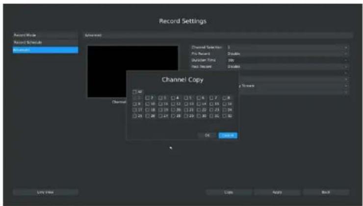
text_image
Record Settings Record Mode Record Schedule Record Advanced Channel Selection: 1 Play Record: Disks Duration Time: 00s Rest Record: Disks Channel Copy OK Cancel Live Now Copy Apply BackF-3.4.15
3.5 Event Settings
3.5.1 Motion Detection
Your NVR can be setup to motion detect and trigger an action. You can set the motion detection
on NVR or on IPC web, both sides' settings will be synchronous in both devices.
Step1. Click Main Men Event → Motion Detection.
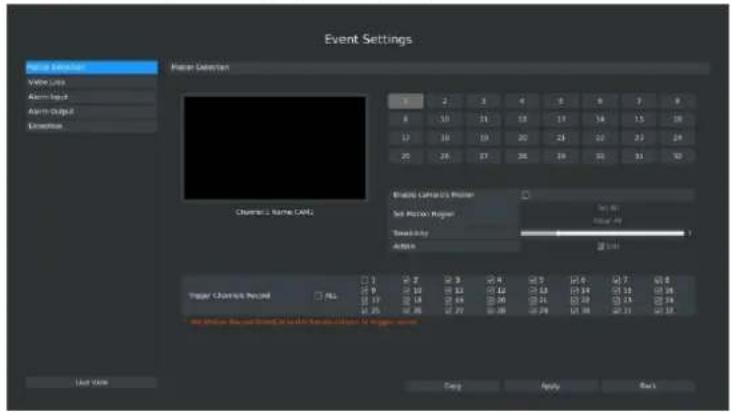
text_image
Event Settings Power Detector Volume Line Alarm Input Alarm Output Categories Channel 1 Name CALLS Brands Latency & Filter Soft Motion Razer Noise Int Audio 20.00 20.00 20.00 20.00 20.00 20.00 20.00 20.00 20.00 20.00 20.00 20.00 20.00 20.00 20.00 20.00 20.00 20, 3, 4, 5, 6, 7, 8 8, 10, 11, 12, 13, 14, 15, 16, 17, 18, 19, 20, 21, 22, 23, 24, 25, 26, 27, 28, 29, 30, 31, 32, 33, 34, 35, 36, 37, 38, 39, 40, 41, 42, 43, 44, 45, 46, 47, 48, 49, 50, 51, 52, 53, 54, 55, 56, 57, 58, 59, 60, 61, 62, 63, 64, 65, 66, 67, 68, 69, 70, 71, 72, 73, 74, 75, 76, 77, 78, 79, 80, 81, 82, 83, 84, 85, 86, 87, 88, 89, 90, 91, 92, 93, 94, 95, 96, 97, 98, 99, 100 Trigger Channels Record #A: A/A B: A/C D: A/D E: A/E F: A/G H: A/G I: A/G J: A/G K: A/G L: A/G M: A/G N: A/G O: A/G P: A/G Q: A/G R: A/G S: A/G T: A/G U: A/G V: A/G W: A/G X: A/G Y: A/G Z: A/G AA: A/G AB: A/G AC: A/G AD: A/G AE: A/G AF: A/G AG: A/G AH: A/G AI: A/G AJ: A/G AK: A/G AL: A/G AM: A/G AN: A/G AO: A/G AP: A/G AQ: A/G AR: A/G AS: A/G AT: A/G AU: A/G AV: A/G AW: A/G AX: A/G AXY: A/G AXZ: A/G AXZY: A/G AXZY: A/G AXZY: A/G AXZY: A/G AXZY: A/G AXZY: A/G AXZY: A/G AXZY: A/G AXZY: A/G AXZY: A/G AXZY: A/G AXZY: A/G AXZY: A/G AXZY: A/ User Size Copy Apply BackF-3.5.1
Step2. Set the trigger area for motion detection.
You can set the area by dragging the mouse on live view window:
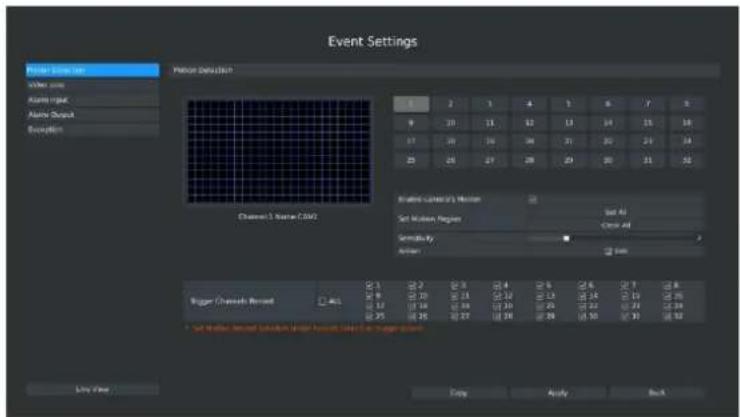
text_image
Event Settings Pulse Detection Noise Other Alarm output Alarm Output Explanations Channel 1 Name CMZ Signal Detection 1 2 3 4 5 6 7 8 9 10 11 12 13 14 15 16 17 18 19 20 21 22 23 25 26 27 28 29 30 31 32 Set Motion Region Set All Clear All Sensitivity: Action Sigma Sugar Channels Bound 0.1 0.2 0.3 0.4 0.5 0.6 0.7 0.8 0.9 1.0 1.1 1.2 1.3 1.4 1.5 1.6 0.12 0.18 0.26 0.33 0.40 0.48 0.56 0.25 0.35 0.47 0.56 0.64 0.26 0.36 0.48 0.56 0.26 0.36 0.48 0.56 * Set Motion, Select Saturation Level Function; Select Data Manager values. Live Now Copy Apply BackF-3.5.2
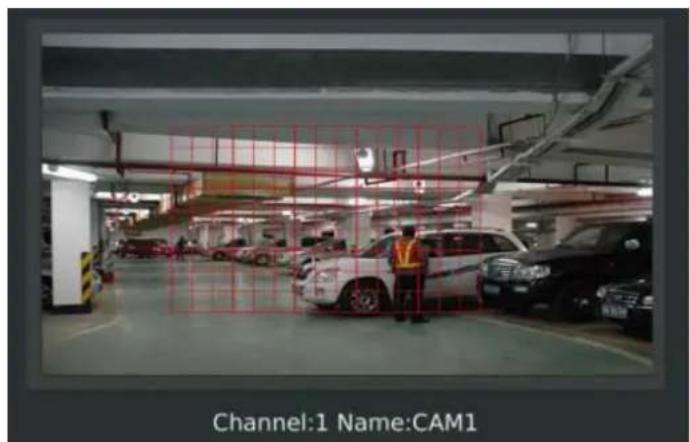
text_image
Channel:1 Name:CAM1F-3.5.3
And meanwhile the area will be synchronized to Camera.
Step3. Select the schedule, sensitivity and trigger area for motion detection.
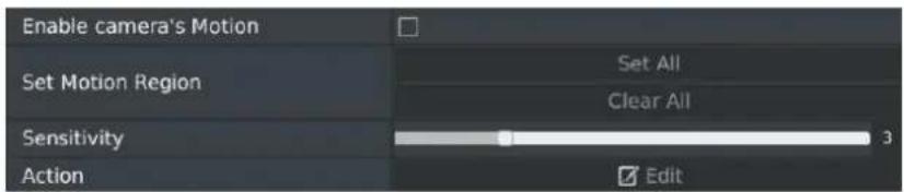
text_image
Enable camera's Motion Set Motion Region Set All Clear All Sensitivity 3 Action Edit[Enable camera's Motion]: If it is enabled here, motion detect will take effect 7*24h; If it is not enabled, motion detect will take effect as the schedule which is set on the camera web.
[Set All]: Set all area as the trigger area;
[Clear All]: Clear all trigger area;
[Sensitivity]: Set sensitivity for motion detection, range from 1 to 10. It will synchronize to IPC if you set sensitivity here;
[Action]: Edit action once motion is detected, refers to next step;
Step4. Select the desired channel and click [Edit] to configure motion detection action.
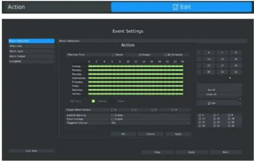
text_image
Action Edit Event Settings Motion Detection Action Effective Time Never Always By Schedule Sunday Monday Tuesday Wednesday Thursday Friday Saturday Holiday Add Time Trigger Alert Output Add Article Warning Email Linkages Triggered Interval 1 2 3 4 Enable Warning Enable Linkages Triggered Interval Enable Set All Clear All Edit OK Cancel Apply Copy Apply BackF-3.5.4
Step5. Select effective time to setup when you want to trigger actions once motion is detected.

text_image
Effective Time ✓ Never □ Always □ By Schedule[Never]: Your NVR will not trigger any actions when [Never] button is checked. No matter the [Audible Warning] or [Email Linkage] check-boxes are checked or not.
[Always]: Your NVR will always trigger actions when [Always] button is checked. Please make sure [Audible Warning] or [Email Linkage] is checked.
[By Schedule]: You can drag the mouse to draw certain area in schedule setting zone, see F-3.5.12:
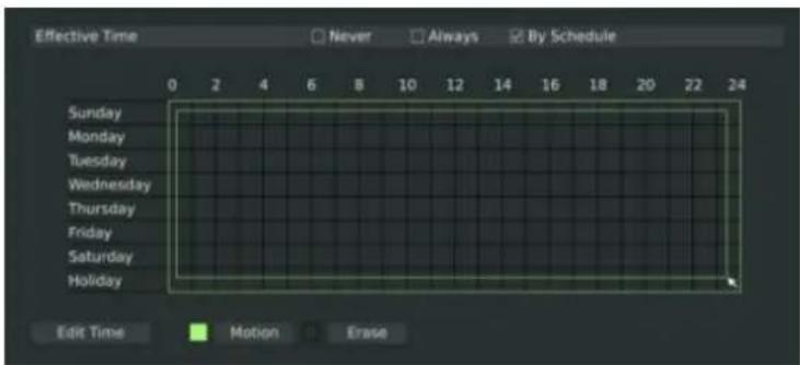
text_image
Effective Time Never Always By Schedule Sunday Monday Tuesday Wednesday Thursday Friday Saturday Holiday Edit Time Motion EraseF-3.5.5
After dragging, this channel will show as below:
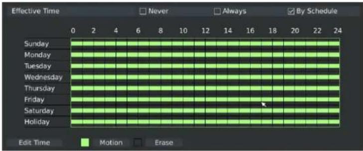
text_image
Effective Time Never Always By Schedule Sunday Monday Tuesday Wednesday Thursday Friday Saturday Holiday Edit Time Motion EraseF-3.5.6
Or click [Edit Time] to setup schedules. Schedule can be set for all week or any day of the week with up to 12 time periods per day. Motion detection actions take effect in the scheduled period only.
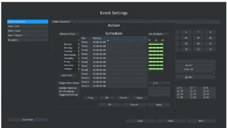
text_image
Event Settings Action Schedule By Schedule 9 7 8 14 15 16 22 23 24 35 36 37 Set A1 Clear A1 Tab Copy Copy Cancel Apply OK Cancel Apply Live Window Copy Apply BackF-3.5.7
Note:
Time period cannot overlap with each other
Step6. Click [Copy] to copy the motion detection schedules to other weekdays.
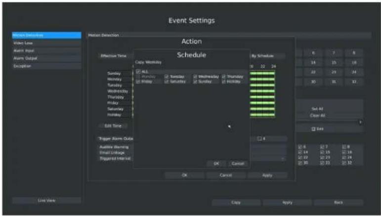
text_image
Event Settings Action Schedule By Schedule 6 7 8 14 15 16 22 23 24 30 31 32 Set All Clear All Add OK Cancel Apply Live View Copy Apply BackF-3.5.8
Step7. Select actions you want when motion is detected

text_image
Trigger Alarm Output □ 1 □ 2 □ 3 □ 4 Audible Warning □ Enable Email Linkage □ Enable Triggered Interval 20s[Trigger Alarm Output]: Select whether trigger the alarm output or not when video loss is detected.
[Audible Warning]: NVR will trigger an audible beep when motion is detected.
[Email Linkage]: Send video loss note to specified email address when video loss is detected.(Please refer to 3.8.2.4 Mail configuration for mail address setting).
[Triggered Interval]: Set the interval between two events.
Note:
These actions will only take response according to effective time you choose.
Step8. [Trigger Channels Record]: Select the channels that you want to trigger recording when motion is detected by checking the check-boxes with corresponded channel numbers. Please make sure that the checked channels have setup motion detection record schedule. (Refer to 3.4 Record settings)
| Trigger Channels Record | ALL | 1 | 2 | 3 | 4 | 5 | 6 | 7 | 8 |
| 9 | 10 | 11 | 12 | 13 | 14 | 15 | 16 | ||
| 17 | 18 | 19 | 20 | 21 | 22 | 23 | 24 | ||
| 25 | 26 | 27 | 28 | 29 | 30 | 31 | 32 |
Step9. Click [Apply] or [OK] to confirm settings. Repeat above steps to other channel. Or click [Copy] to copy settings to other channel.
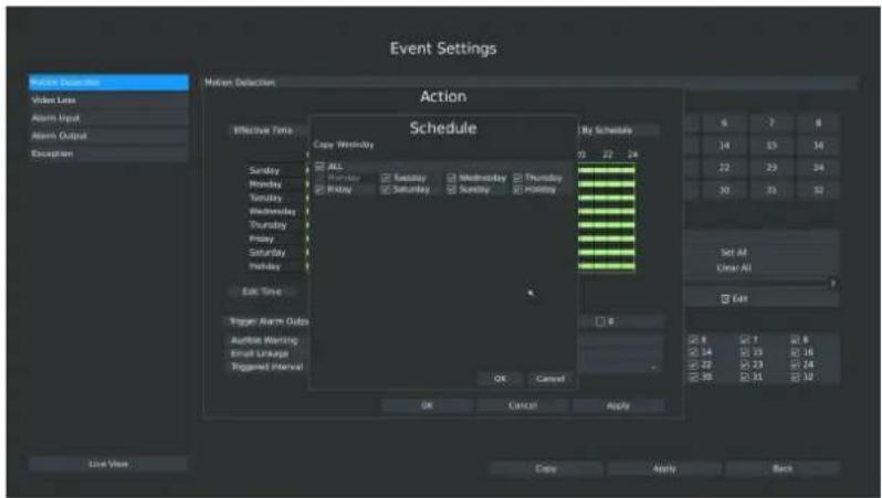
text_image
Event Settings Action Schedule By Schedule 6 7 8 14 15 16 22 23 24 30 31 32 Set All Clear All Edit OK Cancel Apply Live View Copy Apply BackF-3.5.9
3.5.2 Video Loss
Your NVR can be setup to detect video loss and trigger an action.
Step1. Click Main Menu → Event → Video Loss.
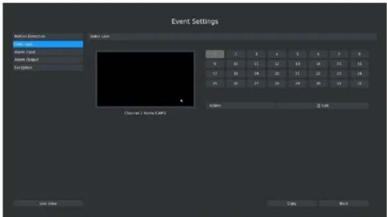
text_image
Event Settings Noise Detector Text Lins Alarm Input Alarm Output Exception Video Lins Channel 1 Name.CAP1 Action List Info Copy BackF-3.5.10
Step2. Select a desired channel and click [Edit] to configure video loss.
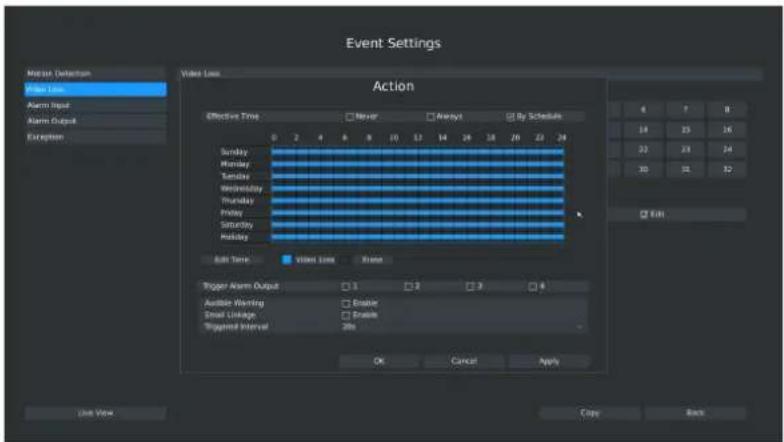
text_image
Event Settings Mean Detection Line Line Alarm Input Alarm Output Exception Video Line Action Effective Time: Never Always By Schedule 0 2 4 6 8 10 12 14 16 18 20 22 24 Sunday Monday Tuesday Wednesday Thursday Friday Saturday Sunday Edit Time: Video Lines None Trigger Alarm Output: 1 2 3 4 Audible Writing: Enable Email Linkage: Enable Trigger Interval: 3ms OK Cancel Apply 4 7 8 19 25 16 22 23 24 30 31 32 EditF-3.5.11
Step3. Select effective time to setup when you want to trigger actions once video loss is
detected.

text_image
Effective Time ✓ Never □ Always □ By Schedule[Never]: Your NVR will not trigger any actions when [Never] button is checked. No matter the [Audible Warning] or [Email Linkage] check-boxes are checked or not.
[Always]: Your NVR will always trigger actions when [Always] button is checked. Please make sure [Audible Warning] or [Email Linkage] is checked.
[By Schedule]: You can drag the mouse to draw certain area in schedule setting zone, show as below:
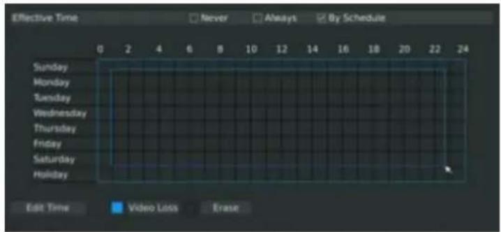
text_image
Effective Time Never Always By Schedule Sunday Monday Tuesday Wednesday Thursday Friday Saturday Holiday Edit Time Video Loss EraseF-3.5.12
After dragging this will show as below:
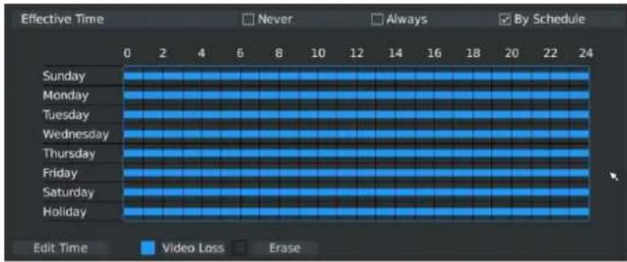
text_image
Effective Time Never Always By Schedule 0 2 4 6 8 10 12 14 16 18 20 22 24 Sunday Monday Tuesday Wednesday Thursday Friday Saturday Holiday Edit Time Video Loss EraseF-3.5.13
Or click [Edit Time] to set schedules. Schedule can be set for all week or any day of the week with up to 12 time periods per day. Video loss actions take effect in the scheduled period only.
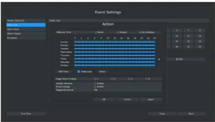
text_image
Event Settings Monitor Detection Show Time Alarm Input Alarm Output Exception Video Loss Action Effective Time Never Always By Schedule Sunday Monday Tuesday Wednesday Thursday Friday Saturday Holiday Edit Time Video Loss Brack Trigger Alert Output Audience Warning Alert Linkage Supported Interval Inverse Enable OK Cancel Apply 0 7 9 14 15 16 22 23 24 35 31 32 OK Back Use View Copy BackF-3.5.14
Note:
Time periods cannot overlap with each other.
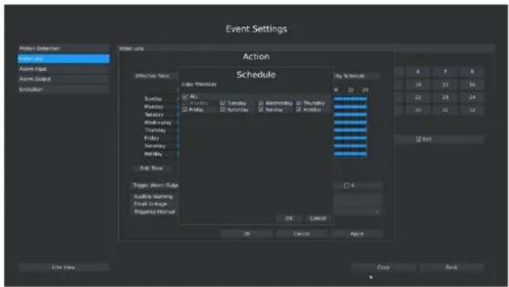
Step4. Click [Copy] to copy the video loss schedule to other weeks, and then click [OK].
text_image
Event Settings Action Schedule Copy Wednesday ALL Friday Thursday Friday Wednesday Thursday Friday Saturday Sunday Sunday Buy Now Trigger Alert Date Audio Warning Event Schedule Regulated Notice OK Cancel Apply Line View Cancel BackF-3.5.15
Step5. Select actions you want when video loss is detected.

text_image
Trigger Alarm Output □ 1 □ 2 □ 3 □ 4 Audible Warning □ Enable Email Linkage □ Enable Triggered Interval 20s[Trigger Alarm Output]: Select whether trigger the alarm output or not when video loss is detected.
[Audible Warning]: NVR will trigger an audible beep when motion is detected.
[Email Linkage]: Send video loss note to specified email address when video loss is detected. (Please refer to 3.8.2.4 Mail configuration for mail address setting).
[Triggered Interval]: Set the interval between two events.
Note:
These actions will only take response according to effective time you choose
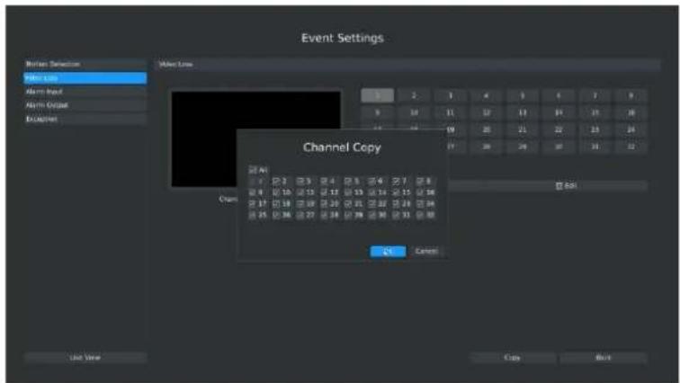
Step6. Click [OK] or [Apply] to confirm the settings. Repeat above steps for other channels. Or click [Copy] to copy settings to other channels.
text_image
Event Settings Motion Detection Motion Loss Motion Input Motion Output Exclusions Motion Loss Channel Copy Flow 40 Flow 2 Flow 3 Flow 4 Flow 5 Flow 6 Flow 7 Flow 8 Flow 9 Flow 10 Flow 11 Flow 12 Flow 13 Flow 14 Flow 15 Flow 16 Flow 17 Flow 18 Flow 19 Flow 20 Flow 21 Flow 22 Flow 23 Flow 24 Flow 25 Flow 26 Flow 27 Flow 28 Flow 29 Flow 30 Flow 31 Flow 32 Flow 33 Flow 34 Flow 35 Flow 36 Flow 37 Flow 38 Flow 39 Flow 40 Flow 41 Flow 42 Flow 43 Flow 44 Flow 45 Flow 46 Flow 47 Flow 48 Flow 49 Flow 50 Flow 51 Flow 52 Flow 53 Flow 54 Flow 55 Flow 56 Flow 57 Flow 58 Flow 59 Flow 60 Flow 61 Flow 62 Flow 63 Flow 64 Flow 65 Flow 66 Flow 67 Flow 68 Flow 69 Flow 70 Flow 71 Flow 72 Flow 73 Flow 74 Flow 75 Flow 76 Flow 77 Flow 78 Flow 79 Flow 80 Flow 81 Flow 82 Flow 83 Flow 84 Flow 85 Flow 86 Flow 87 Flow 88 Flow 89 Flow 90 Flow 91 Flow 92 Flow 93 Flow 94 Flow 95 Flow 96 Flow 97 Flow 98 Flow 99 Flow 100F-3.5.16
3.5.3 Alarm Input
Alarm Input function is supported in some specific models. Please make sure your NVR has such function first.
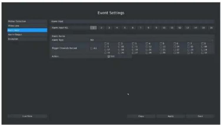
Step1. Select Main Menu - Event - Alarm Input.
text_image
Event Settings Motor Detection Wire Loss Alarm Size Alarm Input NO. Alarm Size NO. Trigger Channels Record Action Size Save Now Copy Auto BackF-3.5.17
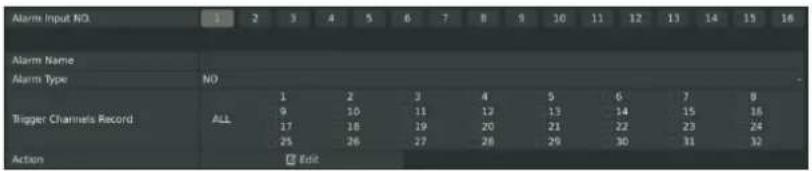
Step2. Set Alarm input channel, Alarm Name, Alarm Type and Record Channels.
text_image
Alarm Input NO 1 2 3 4 5 6 7 8 9 10 11 12 13 14 15 16 Alarm Name Alarm Type NO ALL 1 2 3 4 5 6 7 8 9 10 11 12 13 14 15 16 17 18 19 20 21 22 23 24 25 26 27 28 29 30 31 32 Action EditF-3.5.18
[Alarm Input NO]: The channel which has input signal;
[Alarm Name]: Set a name for the alarm;
[Alarm Type]: Select alarm type: NO or NC;
[Trigger Channels Record]: Once the channel in the [Alarm Input No] has alarm input, which channels will be triggered to record. Refer to 3.4 Record Settings;
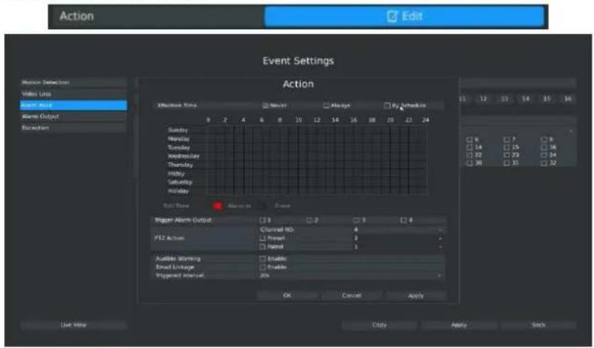
Step3. Set action for alarm input.
text_image
Action Edit Event Settings Action Efficient Total Never Always By CheckLine Sunday Monday Tuesday Wednesday Thursday Friday Saturday Sunday Birth Time Abnormal Force Trigger Alarm Output Channel NO 4 F12 Action Pretest 2 Panel 1 Audible Storming Enable Enable Fixed Linkage Enable Trigger Alert OK Cancel Apply Use Now Entry Apply BackF-3.5.19
You need to set 1.Effective time and 2.Action on this Action Interface:
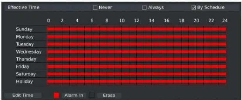
1. Effective time:
text_image
Effective Time Never Always By Schedule Sunday Monday Tuesday Wednesday Thursday Friday Saturday Holiday 0 2 4 6 8 10 12 14 16 18 20 22 24 Edit Time Alarm In EraseF-3.5.20
You can set three different modes for effective time:
[Never]: Will have no action triggered if it is checked;
[Always]: Will always trigger the action if checked;
[By Schedule]: Will take effect by the schedule you set.
If you choose By Schedule, you need to set schedule by 1.drag the mouse on the time schedule area or 2.by click the "Edit Time" button.
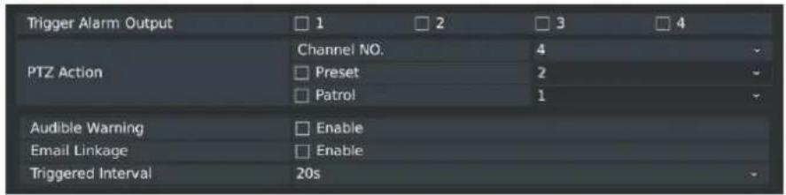
2. Action
text_image
Trigger Alarm Output PTZ Action Audible Warning Email Linkage Triggered Interval 1 2 3 4 Channel NO. 4 Preset 2 Patrol 1 Enable Enable 20sF-3.5.21
[Trigger Alarm Output]: Select whether trigger the alarm output or not when video loss is detected.
[PTZ Action]: NVR will trigger a linkage function of PTZ network camera when alarm is detected.
[Audible Warning]: NVR will trigger an audible beep when motion is detected.
[Email Linkage]: Send video loss note to specified email address when video loss is detected. (Please refer to 3.8.2.4 Mail configuration for mail address setting).
[Triggered Interval]: Set the interval between two events.
Note:
These actions will only take response according to effective time you choose. Lastly need to APPLY these settings to take effect.
3.5.4 Alarm Output
Alarm Input function is supported in some specific models. Please make sure your NVR has such function first.
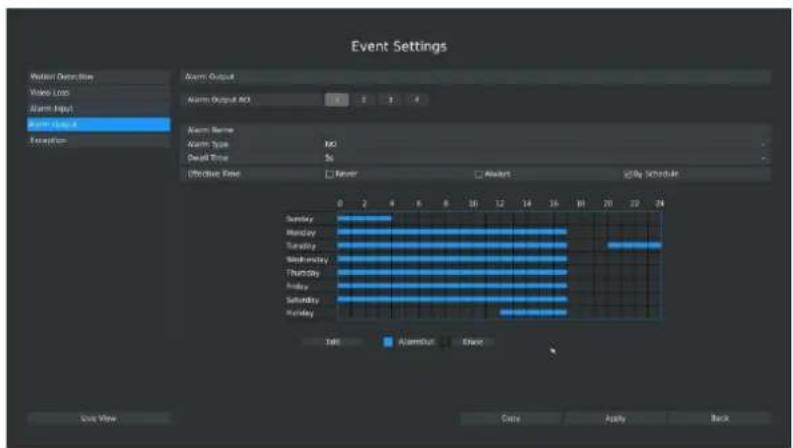
Step 1. Select Main Menu-Event-Alarm Output:
text_image
Event Settings Motion Detection Wave Loss Alarm Input Alarm Output Execution Alarm Output Alarm Output NO Alarm Type Alarm Type Dead Time Effective Time Server Alert By Schedule Sunday Monday Tuesday Wednesday Thursday Friday Saturday Friday 0 2 4 6 8 10 12 14 16 18 20 22 24 Tall Audio/Out Show Copy Apply Back Exit NowF-3.5.22
Step 2. Set Alarm output channel, Alarm Name, Alarm Type and Record Channels:
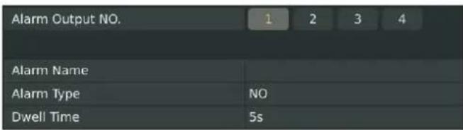
text_image
Alarm Output NO. 1 2 3 4 Alarm Name Alarm Type NO Dwell Time 5sF-3.5.23
[Alarm Output NO]: The channel which will output the alarm signal;
[Alarm Name]: Set a name for the alarm;
[Alarm Type]: Select alarm type: NO or NC;
[Dwell Time]: Set the output time for alarm, if that is too long when alarm out is outputting, you can select the Manually Clear to stop it.
Step3. Select Effective Time for alarm output:
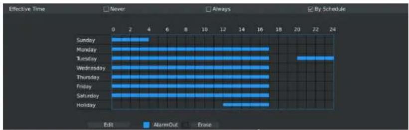
bar
| Day | Edit | AlarmOut | Erase | |---|---|---|---| | Sunday | 0 | 3 | 0 | | Monday | 0 | 17 | 0 | | Tuesday | 0 | 24 | 0 | | Wednesday | 0 | 17 | 0 | | Thursday | 0 | 17 | 0 | | Friday | 0 | 17 | 0 | | Saturday | 0 | 17 | 0 | | Holiday | 0 | 17 | 0 |F-3.5.24
You can set three different modes for effective time:
[Never]: Will have no action triggered if it is checked;
[Always]: Will always trigger the action if checked;
[By Schedule]: Will take effect by the schedule you set.
If you choose By Schedule, you need to set schedule by 1.drag the mouse on the time schedule area or 2.by click the "Edit Time" button.
Lastly need to APPLY these settings to take effect.
3.5.5 Exception
Milesight NVR support exception alarm for 1. Network Disconnected; 2.HDD Full; 3.Record Failed; 4.HDD Failed; 5.HDD Unformat; 6.No Disk;
Step1. Click Main Ment Event → Exception;

text_image
Event Settings Motion Detection Video Loss Audio Input Audio Output Exception Exception Type Networks Disinjected Normal Linkage □ Pop-Up Warm □ Audio Striping □ Audio Striping Use View Apply BackF-3.5.25
Step2. Select Exception Type;
There are 4 kinds of alarm type:
[Network Disconnected]: Lost of network;
[HDD Full]: HDD full, it usually happens when Recycle Mode is OFF.
[Record Failed]: Recording fails, including HDD Failed, HDD Full, No Disk and so on.
[HDD Failed]: Failed to recognize HDD.
[HDD Unformat]: When HDD unformat.
[No Disk]: When there is no disk.
Step3. Select Alarm Type;
[Pop Up Alarm]: Will pop up a window if checked;
[Audible Warning]: NVR will trigger an audible beep when motion is detected;
[Email Linkage]: Will send alarm Email if checked.
3.6 Status
You can have a quick view of the information of the device, network, camera, disk and event. This part is only for your rapid reference. If you want to make any configuration, please go to corresponding parts accordingly.
3.6.1 Device Information
Click Main Menu → Status → Device Information
It will show you information in F-3.6.1, including: Device ID, Device Name, MAC Address, Hardware Version, Software Version, and Up Time.
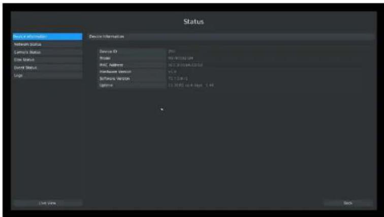
text_image
Status Device Information Network Status System Status Data Status Event Status Logic Device Information Device ID Type PCB Address Surface Value Software Version Name 12.3017 or 4 days - 1.44 Use View BackF-3.6.1
3.6.2 Network Status
Click Main Menu → Status → Network Status
It will show you information in F-3.6.2, including: Connection, Mode, DHCP, MTU(B), IP Address, Net mask, Gateway, MAC, Preferred DNS Server, Alternate DNS Server, Receive Rate, and Send Rate.
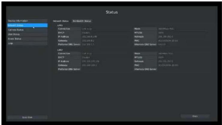
text_image
Status Device Information Bluetooth Status Camera Status Disk Status Server Status Link Network Status Bandwidth Status LRP1 Connection DHCP P Address Gateway Preferred DNS Server LAN2 LAN3 LAN4 LAN5 LAN6 LAN7 LAN8 LAN9 LAN10 LAN11 LAN12 LAN13 LAN14 LAN15 LAN16 LAN17 LAN18 LAN19 LAN20 LAN21 LAN22 LAN23 LAN24 LAN25 LAN26 LAN27 LAN28 LAN29 LAN30 LAN31 LAN32 LAN33 LAN34 LAN35 LAN36 LAN37 LAN38 LAN39 LAN40 LAN41 LAN42 LAN43 LAN44 LAN45 LAN46 LAN47 LAN48 LAN49 LAN50 LAN51 LAN52 LAN53 LAN54 LAN55 LAN56 LAN57 LAN58 LAN59 LAN60 LAN61 LAN62 LAN63 LAN64 LAN65 LAN66 LAN67 LAN68 LAN69 LAN70 LAN71 LAN72 LAN73 LAN74 LAN75 LAN76 LAN77 LAN78 LAN79 LAN80 LAN81 LAN82 LAN83 LAN84 LAN85 LAN86 LAN87 LAN88 LAN89 LAN90 LAN91 LAN92 LAN93 LAN94 LAN95 LAN96 LAN97 LAN98 LAN99 LAN100F-3.6.2
3.6.3 Camera Status
Click Main Menu→ Status → Camera Status
It will show you information in F-3.6.3, including: Channel, Name, Status, IP Address, Record, Frame Rate, Bit rate, and Resolution. The PoE Channel Status is only for PoE NVR, it will show you the connection status of PoE ports.

text_image
Status Device Information Network Status Current Status 3 4 5 6 7 8 9 10 11 12 13 14 15 16 17 18 19 20 21 22 23 24 25 26 27 28 29 30 31 32 33 34 35 36 37 38 39 40 41 42 43 44 45 46 47 48 49 50 51 52 53 54 55 56 57 58 59 60 61 62 63 64 65 66 67 68 69 70 71 72 73 74 75 76 77 78 79 80 81 82 83 84 85 86 87 88 89 90 91 92 93 94 95 96 97 98 99 100F-3.6.3
3.6.4 Disk Status
Click Main Menu → Status → Disk Status
It will show you information in F-3.6.4, including: Port, Vendor, Status, Total(GB), Free(GB), HDD Type, In Use, and Recycle Mode. You can see the Total Capacity (GB) and Available Capacity (GB) as below:
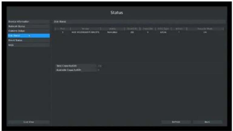
text_image
Status Device Information Network Status Waiting Status Sub-Serial Direct Status Keys Sub Status Type | Type | Status | Start Date | Interrupt Date | After Time | Next User Work 3 WCC: Microsoft 1962.07.1 New Date: 202 80% 90% 100% 80% 11% New Capacity: 100% Available Capacity: 100% Line View Refresh BackF-3.6.4
3.6.5 Event Status
3.6.5.1 Alarm Status
Click Main Menu → Status → Event Status
It will show you the Alarm Input List in F-3.6.5.
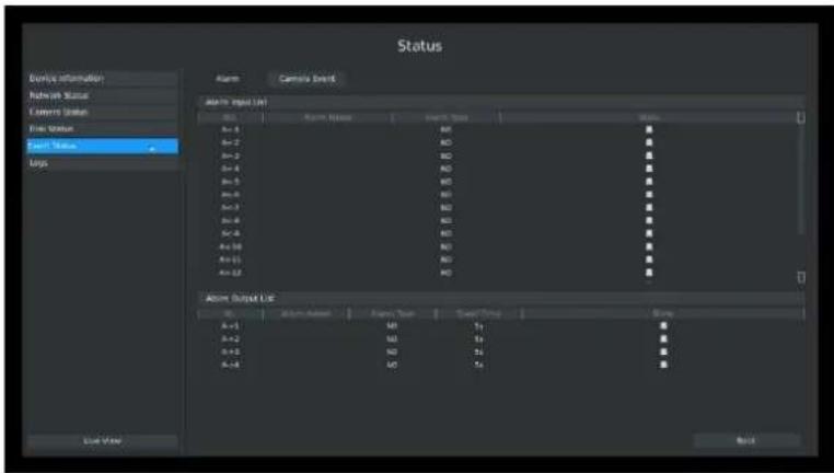
text_image
Status Device Information Network Status Camera Status Fire Status Smart Value Logo Alarm Camera Event Alarm Input List A=1 A=2 A=3 A=4 A=5 A=6 A=7 A=8 A=9 A=10 A=11 A=12 A=13 A=14 A=15 A=16 A=17 A=18 A=19 A=20 A=21 A=22 A=23 A=24 A=25 A=26 A=27 A=28 A=29 A=30 A=31 A=32 A=33 A=34 A=35 A=36 A=37 A=38 A=39 A=40 A=41 A=42 A=43 A=44 A=45 A=46 A=47 A=48 A=49 A=50 A=51 A=52 A=53 A=54 A=55 A=56 A=57 A=58 A=59 A=60 A=61 A=62 A=63 A=64 A=65 A=66 A=67 A=68 A=69 A=70 A=71 A=72 A=73 A=74 A=75 A=76 A=77 A=78 A=79 A=80 A=81 A=82 A=83 A=84 A=85 A=86 A=87 A=88 A=89 A=90 A=91 A=92 A=93 A=94 A=95 A=96 A=97 A=98 A=99 A=100F-3.6.5
3.6.5.2 Camera Event Status
Click Main Menu → Status → Event Status.
It will show you the camera event status in F-3.6.6. If the shows in red, it means the corresponding project is active.
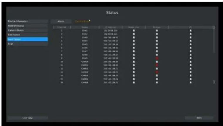
text_image
Status Device Information Alarms C:\Users\* Reboot Status Cathode Status Eink Status Term Status Login Control 1 2 3 4 5 6 7 8 9 10 11 12 13 14 15 16 17 18 19 20 21 22 23 24 25 26 27 28 29 30 31 32 33 34 35 36 37 38 39 40 41 42 43 44 45 46 47 48 49 50 51 52 53 54 55 56 57 58 59 60 61 62 63 64 65 66 67 68 69 70 71 72 73 74 75 76 77 78 79 80 81 82 83 84 85 86 87 88 89 90 91 92 93 94 95 96 97 98 99 100F-3.6.6
3.7 Live View Settings
3.7.1 Live View
Watching a Live View
It can display rotating mode of cameras on the Live View interface. There are multiple icons on each channel displayed in live view mode, indicating the recording and alarm status of the channel.
| Icons | Descriptions |
 | Indicates video loss |
 | Indicates motion detection alarm |
 | Indicates that the current channel is recording. The recording may be start manually, or triggered by record schedule(Motion Detection, Alarm, Motion Detection or Alarm, Motion Detection and Alarm). |
 | Indicates exception alarm and recording. |
Use the Right Button of the Mouse in Live View
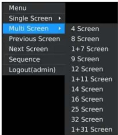
text_image
Menu Single Screen ▶ Multi Screen ▶ 4 Screen Previous Screen 8 Screen Next Screen 1+7 Screen Sequence 9 Screen Logout(admin) 12 Screen 1+11 Screen 14 Screen 16 Screen 25 Screen 32 Screen 1+31 ScreenF-3.7.1
| Item | Description |
| Menu | Enter main menu |
| Single Screen | The channel chosen will spread the whole screen. You could also reve. function by double clicking the channel |
| Sub Screen Ctrl | Switch to sub screen to operate(only for MS-N8000 series) |
| Multi Screen | Change the screen layouts |
| Previous Screen | Switch to the previous screen |
| Next Screen | Switch to the next screen |
| Sequence | Enable single/multi-screen cruise in live view mode |
| Sub Sequence | Enable single/multi-screen cruise for sub screen(only for MS-N8000 seri |
| Logout | Click it to log out current user account |
Quick Operation for Live View
In live view interface; left click the channel, the quick menu will appear. Quick menu operations include recording manually, image configuration, PTZ, original/resize(resize mode can adjust the video to adapt to the screen), audio, digital zoom, and snapshot.
Quick Menu Instructions for Main Output Live View

text_image
Toolbar with application icons including photo, image, cloud, audio, radio, and camera| Icon | Description | Icon | Description | Icon | description |
 | Manually recording |  | Image configure |  | PTZ Control |
 | Original/Resize |  | Sound on/off |  | Electronic Amplification |
 | Snapshot manually |  | Close |
3.7.2 Layout Configuration
Step1. Click Main Ment→ Live View→ Layout configuration
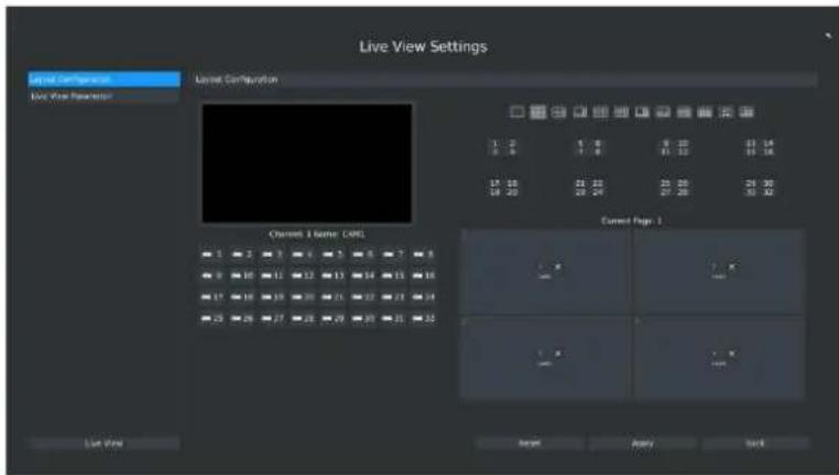
text_image
Live View Settings Level Configuration Live View Parameters Level Configuration 1 2 3 4 5 6 7 8 9 10 11 12 13 14 15 16 17 18 19 20 21 22 23 24 25 26 27 28 29 30 Current Page 1 Channel 1 Name: CNTL Live View Next Apply BackF-3.7.2
You can choose single screen/4/8/1+7/9/12/1+11/14/16/32 screens for layout configuration according to the model and your need.
Step2. Click to close a channel, or click a desired channel (see F-3.7.3) to add in and then click "Apply" to confirm settings. Click "Reset" to reset the layout.

text_image
1 2 3 4 5 6 7 8F-3.7.3
3.7.3 Live View Parameter
Live View Parameters Settings
Click Main Menu→Live View→Live View Parameter
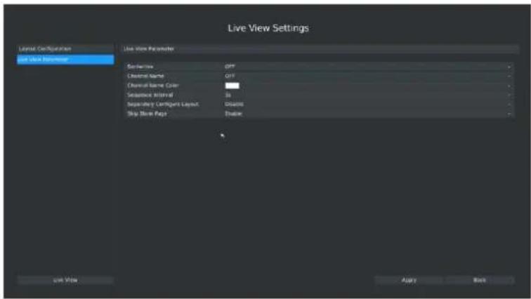
text_image
Live View Settings Layout Configuration Live View Parameter Setters OFF Custom Name OFF Custom Name Color: - Sequence Interval 36 Secondary Config/Layout Disable Skip Book Page Enable OK Apply BackF-3.7.4
| Item | Description |
| Borderline | Borderline ON/OFF |
| Channel Name | Display the channel name |
| Channel Name Color | To change the color of the channel name |
| Sequence Interval | Set sequence interval in live view mode |
| Separately Configure Layout | To configure channel order of all layouts respectively |
| Skip Blank Page | Skip blank page in sequence mode |
3.8 System Settings
3.8.1 General Setting
Click Main Menu→System Settings→General Settings
To setup the general parameters of NVR, including modify the host name, device ID, select resolution, and set system time manually, etc.4
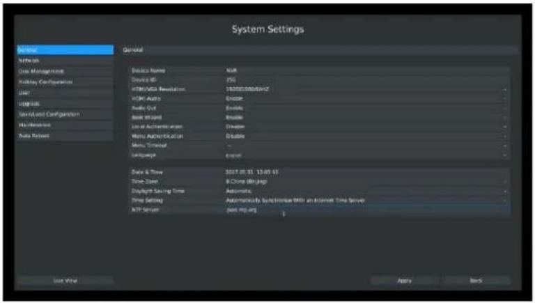
text_image
System Settings Service Network Data Management Holiday Configuration Order Upgrade Send and Configuration No Deviation Auto Select General Basic Names Device ID HKEY/MSA Version HKEY Active Audio Out Base Wizard Local Authentication Menu Authentication Menu Timeout Language Data & Time Time Label Display Saving Time Time Setting TCP Server 2017.07.11 13:05:13 B Change (Relng) Automatic Automatics Syndrome With an Internet Time Server jpm RP.org Use Help Apply BackF-3.8.1
3.8.2 Network Settings
3.8.2.1 Basic Configuration
Click Main Menu → System Settings → Network, select "Basic" page
Basic configuration includes working mode, IP address, subnet mask, gateway, MTU, DNS server, Internal NIC IPv4 Address, etc.
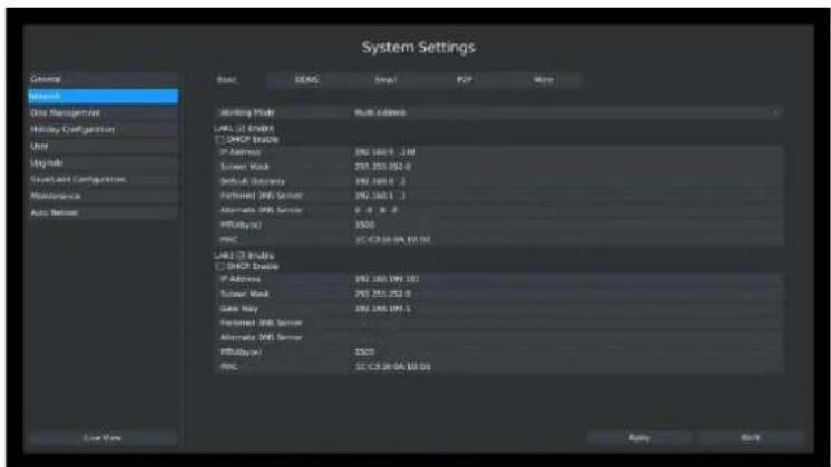
text_image
System Settings General Name Service One Management Hillday Configuration Unit 型号 Serverless Configuration Maintenance Auto Server Base DECK Scale PDF Help Winning Mode Multi address LWU (10000) CC DHCP Address IP Address 192.160.0_248 Server Mask 293.255.052.0 Setup Status 192.160.0_2 Functional (MS) Server 192.160.1_1 Alternate (MS) Server 0.0%_0.0 RPU(s) $500 RMC CC.C.R.06.04.10.03 LWU (10000) CC DHCP Address IP Address 192.160.199.101 Server Mask 293.255.252.0 Gate Bay 192.160.199_1 Functional (MS) Server Alternate (MS) Server RPU(s) $500 RMC CC.C.R.26.04.10.03 Live Now Apply BackF-3.8.2
Note:
- Check the DHCP check-box when there is a DHCP server running in the networks.
- The valid range of MTU is 500\~9676.
- Do not input an IP address conflict with another device.
- Working mode option is only for NVR 7000/8000 series. Internal NIC IPv4 Address is only for PoE NVR.
3.8.2.2 PPPoE Configuration
Click Main Menu→System Settings→Network. Select "PPPoE" page
Check the PPPoE check-box to enable the feature, and then input user name, password and confirm password for PPPoE access.
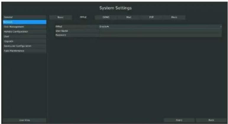
text_image
System Settings Control Name User Name User Name Password User Name User Name User Name User Name User Name User Name User Name User Name User Name User Name User Name User Name User Name User Name User Name User Name User Name User Name User Name User Name User Name User Name User Name User Name User Name User Name User Name User Name User Name User Name User Name User Name User Name User NameF-3.8.3
Note:
- PPPoE user name and password can be obtained from your service provider. Once the setup is completed, a connected status will be shown.
- PPPoE function is not available for 4K/H.265 series NVR.
3.8.2.3 DDNS Configuration
If your NVR is setup to use PPPoE to connect public network, you may need to use DDNS (Dynamic Domain Name System) to solve the problems from dynamic IP address.
Click Main Menu → System Settings → Network, Select "DDNS" page
Check the DDNS check-box to enable the feature. Select "DDNS Server", and input user name, password and host name, and then confirm.
Click [Apply] for application.
Note:
"host name" can use letters, figures and hyphen (-) and must begin with letters.
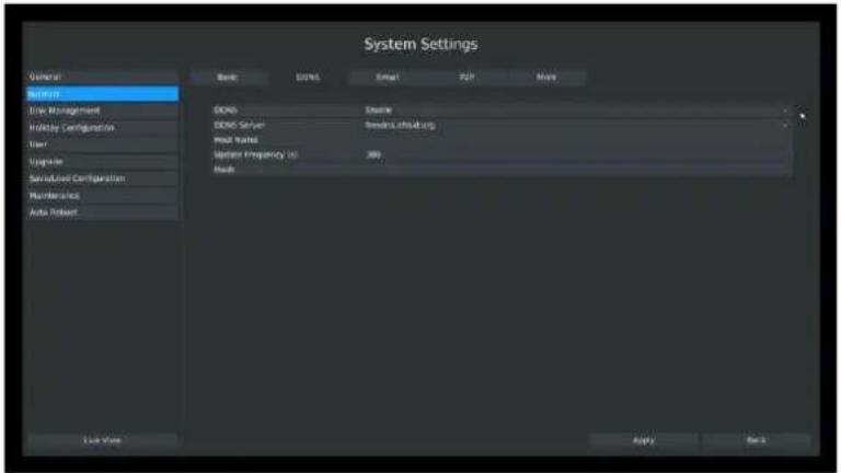
text_image
System Settings General Service File Management Holiday Configuration User Register Sensified Configuration Number of Auto Robot Bank DS/NS Email API More GENO Engine GENO Server Serverless athab.org Mail Name System Frequency (s) 300 Mail Use Value Apply NextF-3.8.4
3.8.2.4 EMAIL Configuration
Click Main Menu → System Settings → Network → Email
Set the Sender E-mail Address, User Name, Password, and SMTP Server:
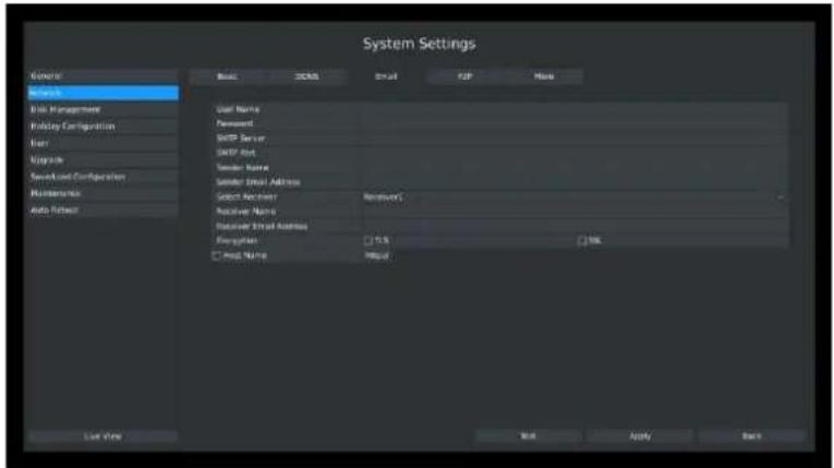
text_image
System Settings General Basis Management Existing Configuration Ferr Upgrade Second and Configuration Maintenance Auto Refresh Base DCMS Email POP Menu User Name Password SMTP Server SMTP Port Sender Name Sender Email Address Select Provider Receiver Name Receiver Email Address Recognition □ No. □ Print Name Input Load View OK Apply BackF-3.8.5
[User name]: The E-mail address you choose to send emails.
[Password]: The password of the E-mail.
[SMTP Server]: The SMTP Server of your E-mail.
[SMTP Port]: The port of SMTP Server, it's usually 25.
[Sender Name]: Named by yourself for the Sender E-mail.
[Sender E-mail Address]: It must be same with [User name].
[Select Receiver]: You can have 3 receivers at the same time.
[Receiver Name]: Named by yourself for the Receiver E-mail.
[Receiver E-mail Address]: E-mail Address for the receivers.
[Encryption]: Security Protocol of email sending, includes TLS and SSL.
[Host Name]: For attaching URL when sending emails. Please enable SSL/TLS according to actual mailbox. (Some SMTP server needs to secure connection)
Select [Test] to check if the Mail function is workable
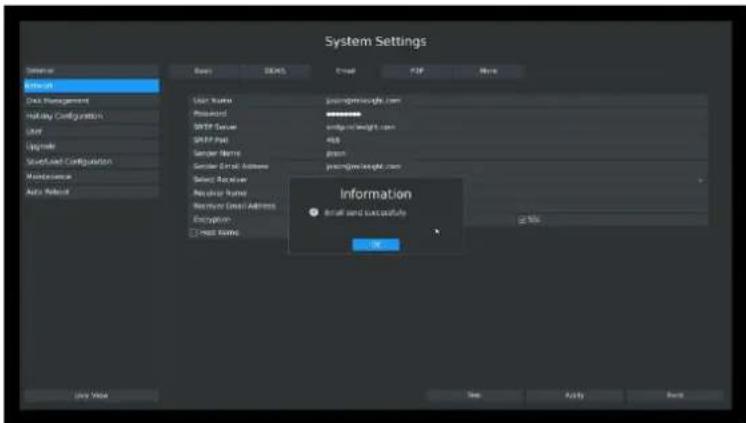
text_image
System Settings Options Data Management Holding Configuration Dart Upgrade Start/End Configuration Maintenance Auto Event Basic STARTS Event POP None User Name: ########## Printed: ########## MRTF Status: ########## SPRIP Status: 400 Sender Name: #2000000000000000000000000000000000000000000000000000000000000000000000000000000000000000000000000 Information Email and successful OK Use Next New Apply BackF-3.8.6
Note:
- Email will send you a screenshot when motion detection is triggered;
- If your NVR has a port forwarding IP for Host Name, please input the complete address that contains the port;
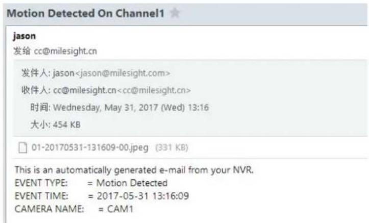
text_image
Motion Detected On Channel1 jason 发给 cc@milesight.cn 发件人: jasonF-3.8.7
3.8.2.5 P2P
You can watch remote NVR live view in WAN by P2P on M-Sight Pro or M-VMS and there is no necessary to port forwarding any router.
Step1. Right click on the live view and choose Menu → System → Network → P2P
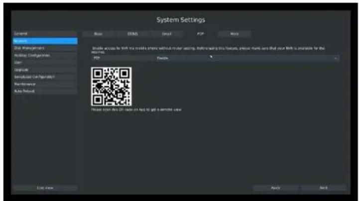
text_image
System Settings General Service Disk Management Holding Configuration User Logistic Sensified Compatibility Performance Auto Protocol Basic access to Web via mobile share without root setting. Setting using this feature, please name sure that your Web is available for the system. USB Security Please select this or best offer to get a security user Use Open Apply HelpF-3.8.8
Step2. Choose "Enable" from the drop-down list of "P2P";
Step3. Apply the settings.
Note:
For security reasons, P2P function need to be registered before being used if your NVR is:
①MS-Nxxxx-UH/UPH and the firmware version is 71.7.0.5-r13 or above;
②MS-Nxxxx-UT/UPT and the firmware version is 72.7.0.5-r13 or above.
You can contact your reseller for help.
If not, just save the information you filled in on "P2P" page.
If NVR failed to save configuration, check these possibilities:
| Marked Words | Description |
| Network Error. | Check the network condition. |
| Register failed. | MAC address doesn’t register the P2P. |
| Unknown Error. | Need to contact with Milesight Support. |
After enabling, you can add the NVR on the APP M-Sight Pro or M-VMS for live view via scanning the QR code on the "P2P" page directly, or inputting the MAC address manually.
3.8.2.6 More
Click Main Menu→System Settings→Network→More
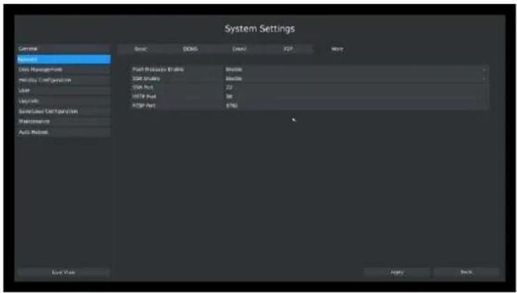
text_image
System Settings General Basic DDNS DQA TCP More Relief Data Management HDMI Configuration User Upgrade Save/Label Configuration Maintenance Auto Protocol Port Protocol (Driver) DDR DDR DDR Port HDMI Port DDR Port Balance Balance Balance 22 36 8762 Live View Apply BackF-3.8.9
Push Message Enable
With this option enabled, you can receive the alarm message on the mobile application(M-Sight Pro or M-VMS).
SSH Port Setting
Secure Shell (SSH) has many functions; it can replace Telnet and also provides a secure channel for FTP, POP, even for PPP.
Note:
The default SSH port is 22.
HTTP Port Setting
The default HTTP port is 80. Please modify HTTP ports according to actual application.
Note:
- The default HTTP port for IE browser is 80.
- HTTP port is used for remote network access.
- The valid range of HTTP port is 80 or 1024\~65535.
RTSP Port Setting
Real Time Streaming Protocol (RTSP) is an application layer protocol in TCP/IP protocol system. The default RTSP port is 554. Please modify RTSP port according to actual application.
Note:
- RTSP port is used for remote network live view.
- The valid range of RTSP port is 554 or 1024\~65535.
Service Port Setting
Service Port is used to get remote access when you add NVR by mobile devices.
The default service port is 1100. Please modify service port according to actual application.
Note:
- This option is not available for 4K/H.265 series NVR.
- You can add this port when using P2P/port mapping/LAN IP to add NVR, but you need to use port 80 to add 4K/H.265 series NVR.
- For port mapping, you still need map 554 to 554. Only then you can use 1100 or 80 to watch the live view by remote WAN.
3.8.3 Disk Management
3.8.3.1 Disk Configuration
Click Main Menu → System Settings → Disk Management → Configuration
Configuration page contains the basic information of the disk, see F-3.8.10. Select a disk and click [Format] to format the disk. After that the disk will stand by.
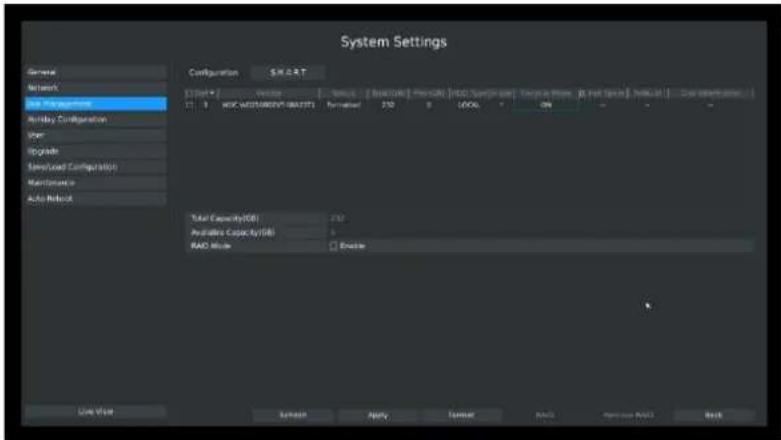
text_image
System Settings General Network Local Management Holiday Configuration User Upgrade Download Configuration Maintenance Auto Release Configuration SHEET [Start] Vector Status [Base Code] PressCount [HDD System User] Origin or Phone [Post Spin] Release Out Color Information 11 B HOC WEDDERMIS (BATT) Format 250 8 LOCAL ON - - - Total Capacity(GB) 250 Prepaid Capacity(GB) 0 RAD Mode Enable Use Value Screen Apply Token Auto Monarch Base BackF-3.8.10
3.8.3.2 RAID Mode
RAID (Redundant Array of Independent Disks) is a storage technology that combines multiple disk drive components into a logical unit. A RAID setup stores data over multiple hard disk drives to provide enough redundancy so that data can be recovered if one disk fails.
RAID(only for MS-N7000 series and MS-N8000 series) will be available after you enable it and reboot the device, including RAID0, RAID1, RAID5 and RAID10.
Note:
RAID 0: With RAID 0, Should one of the disks be damaged, the recordings on all disks will be lost and are not recoverable. It has fastest possible writing and reading speed.
RAID 1: RAID 1 is a solution designed to make mirror copy of from one disk onto one or more disks for recovery purposes, the total available storage will be twice smaller compared to RAID 0.
RAID 5: The check code will store in each disk. Should one of the disks be damaged, it can use the data and check code from other disks to recover the data on the damaged disk.
RAID 10: Combines RAID 1 and RAID 0 configurations - think of it as a group of mirrored disks.
Click Main Menu→System Settings→Disk Management→Configuration
Configuration page contains the basic information of the disks, see F-3.8.11.
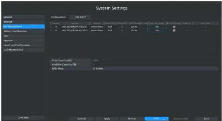
text_image
System Settings General MOSA Bus Management Auxiliary Configuration Reset Upgrade Load/Load Configuration Load Maintenance Configuration START System Control Update Download Update Date Update Time Print Copy Print Copy Print Copy 1.0 WDC WDC/SPR/A/SDS/SDI Unoffset: W3 L1/24:04 On Off - - - 2.0 WDC WDC/SPR/A/SDS/SDI Unoffset: W3 L1/24:04 On Off - - - Total Capacity/CDI Total Available Capacity/CDI Total ADD Mode <5 Enable Line View Refresh Apply Format Edit Remove Help BackF-3.8.11
Step2. Creat a new array by clicking RAID button
Choose the "RAID Type" / "HDD Port", and then check the total capacity.
If the "RAID Capacity" is 0, that means the number of HDD is incorrect.
Click "Create" to finish the configuration. New array will be available after a while.
RAID Create page, see F-3.8.12.
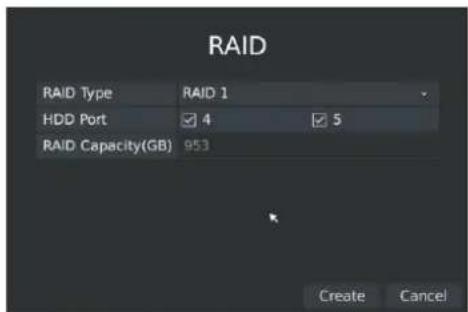
text_image
RAID RAID Type RAID 1 HDD Port 4 5 RAID Capacity(GB) 953 Create CancelF-3.8.12
Note:
RAID0/RAID1 requires at least 2 hard disks;
RAID5 requires at least 3 hard disks;
RAID10 requires 4 hard disks.
[HDD Type]: Show RAID* means RAID, show LOCAL means normal disk mode.
[Recycle Mode]: Enable recycle mode to enable the full disk recycle.
[Hot Spare]: A disk can be used as the hot spare for any array created in the system.
[Rebuild]: When the array is in Degraded status, the device can start rebuilding the array automatically with the hot spare disk to ensure the high security and reliability of the data.
[Disk info]: Click to show the detail information of disk in this array.
Note:
- RAID* stands for RAID0/RAID1/RAID5/RAID10.
- The hot spare disk will be automatically used for rebuilding when array is in Degraded status.
- Currently RAID the capacity can not support larger than 16TB.
3.8.3.3 S.M.A.R.T Detection
Click Main Menu → System Settings → Disk Management → S.M.A.R.T
S.M.A.R.T detection is a monitoring system of HDD that detects anticipating failures of HDD and reports them with various indicators.
You can command S.M.A.R.T self-checking function to check the HDD status.
Select "Test type", and click "apply" for S.M.A.R.T detection.
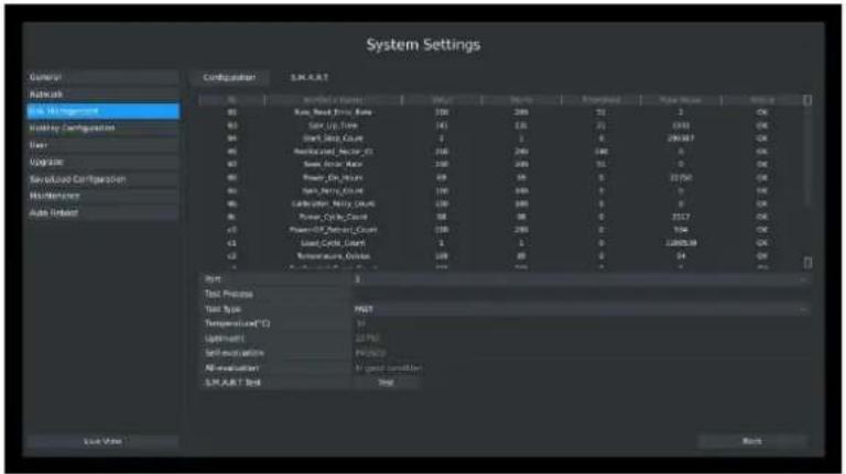
text_image
System Settings General Network BIL Management Utility Configuration User Logistic Sendout Configuration Maintenance Auto Interface Configuration: S.M.R.A.T. 00 00 00 00 00 00 00 00 00 00 00 00 00 00 00 00 00 00 00 00 00 00 00 00 00 00 00 00 00 00 00 00 00 00 1 2 3 4 5 6 7 8 9 10 11 12 13 14 15 16 17 18 19 20 21 22 23 24 25 26 27 28 29 30 31 32 33 34 35 36 37 38 39 40 41 42 43 44 45 46 47 48 49 50 51 52 53 54 55 56 57 58 59 60 61 62 63 64 65 66 67 68 69 70 71 72 73 74 75 76 77 78 79 80 81 82 83 84 85 86 87 88 89 90 91 92 93 94 95 96 97 98 99 100F-3.8.13
Note:
- Test type has [fast] and [full] options.
- Test Status can be [status good], [status bad] and [bad tracks exist].
- Test result can be [passed] or [failed].
3.8.4 Holiday Configuration
It can configure the record or image capture schedule for holidays of the current year.
Step1. Click System Setting Holiday Configuration.
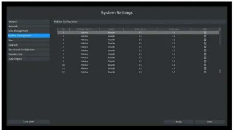
text_image
System Settings General Network Line Management Holiday Configuration Enter Upgrade Second Load Configuration Maintenance Auto Interface Holiday Configuration Color Balance Balance Balance Balance Balance Balance Balance Balance Balance Balance Balance Balance Balance Balance Balance Balance Balance Balance Balance Balance Balance Balance Balance Balance Balance Balance Balance Balance Balance Balance Balance Balance Balance Balance Balance Balance Balance Balance Balance Balance Balance Balance Balance Balance Balance Balance Balance Balance Balance Balance FinishF-3.8.14
Step2. Edit the holiday schedule.
Click ☑ to open holiday configuration page to modify holiday name, check the 'Holiday Enable' check-box, and then select [style] to setup Start/End date. Then click [OK] to save the configuration and return to holiday configuration page. Click [Apply] to confirm settings.
Note:
There are Month, Week and Date in "Style" mode.
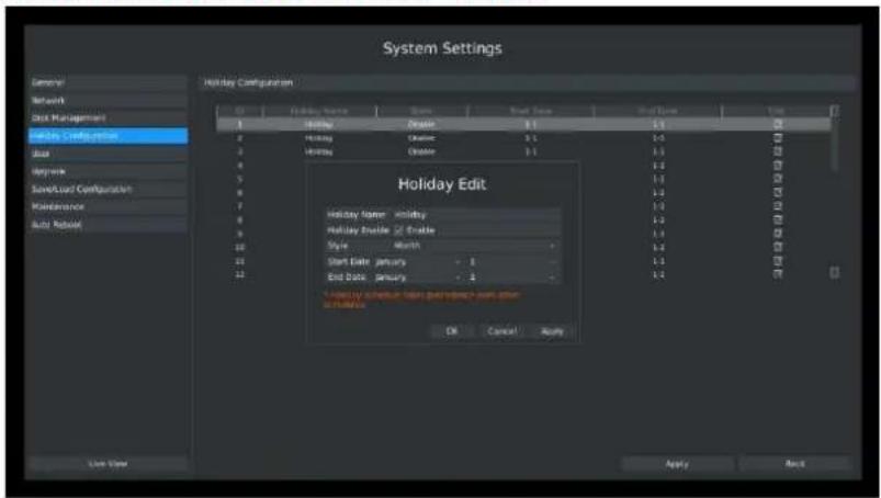
text_image
System Settings General Network Disk Management Holiday Configuration Load Options Save/Load Configuration Maintenance Auto Reboot Holiday Configuration Holiday Edit Holiday Name: Holiday Holiday Enable: Enable Style: Normal Start Date: January - 1 End Date: January - 1 OK Cancel Apply Apply Back Last ViewF-3.8.15
3.8.5 User Account Settings
Add New User
Step1. Click Main Menu → System Settings → User.
Click [Add] to enter the user add menu, input information for the new user, select user level and click [OK].
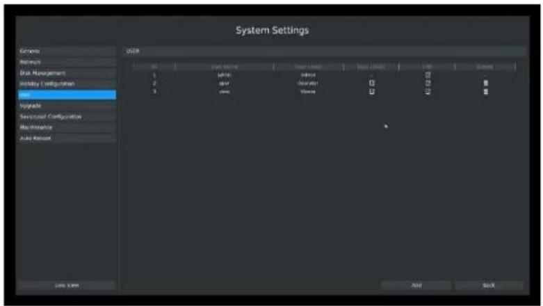
text_image
System Settings General Network Disk Management Utility Configuration Load Updates Service/Load Configuration Maintenance Auto Protocol USER 0 Start Name User Location Load Location Load Settings 1 user user - - - - 2 spot Operator - - - - 3 view Viewy - - - - - - - - - - - - - - - - - - - - - - - - - - - - - - - - - - - - - - - - - - - - - - - - - - - - - - - - - - - - - - - - - - - - - - - - - - - - - - - - - - - - - - - - - - - - - - -F-3.8.16
Note:
- If the NVR firmware version out of the factory is xx.7.0.6 or above, the default user name is "admin" and the default password is "ms1234";
- If the NVR firmware is upgraded to xx.7.0.6 or above from a lower version, the default password will turn to "ms1234" after a reset, or it will keep the old default password "123456";
- If the NVR firmware version is below xx.7.0.6, the default user name is "admin" and the default password is "123456".
Step2. Set user privileges
Select the user that has been added and click [limit] button to enter user privilege menu.
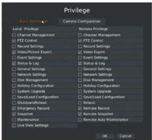
text_image
Privilege Basic Features Camera Configuration Local Privilege Channel Management PTZ Control Record Settings Video/Picture Export Event Settings Status & Log General Settings Network Settings Disk Management Holiday Configuration System Upgrade Save/Load Configuration Shutdown/Reboot Emergency Record Snapshot Maintenance Live View Settings Remote Privilege Channel Management PTZ Control Record Settings Video Export Event Settings Status & Log General Settings Network Settings Disk Management Holiday Configuration System Upgrade Save/Load Configuration Reboot Remote Record Remote Snapshot Remote Auto Maintenance OK Cancel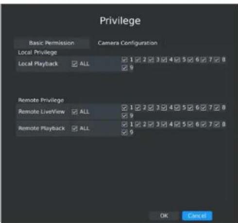
text_image
Privilege Basic Permission Camera Configuration Local Privilege Local Playback ALL 1 2 3 4 5 6 7 8 9 Remote Privilege Remote LiveView ALL 1 2 3 4 5 6 7 8 9 Remote Playback ALL 1 2 3 4 5 6 7 8 9 OK CancelF-3.8.17
Step3. Click to delete a user.
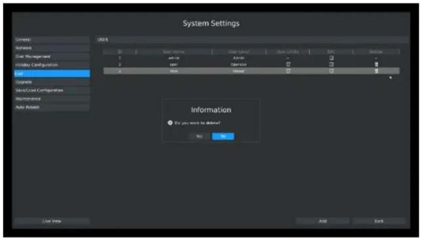
text_image
System Settings General Software Disk Management Holiday Configuration Load Upgrade Speed/Control Configuration Maintenance Auto Robust USTR D User rating User Select User Limits BMI Delete 1 astrs Astrs - ✓ - 2 spor Censor ✓ ✓ # 3 Ins Ins ✓ ✓ # Information Do you want to delete? OK No Live View And BackF-3.8.18
Step4. Click to edit a user.
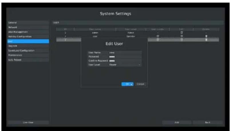
text_image
System Settings General Network Disk Management Holiday Configurations Edit Upgrade Save/Load Configuration Maintenance Auto Assist Edit User User Name: xvxt Password: ****** Confirm Password: ****** User Level: Viewer OK Cancel Add BackF-3.8.19
3.8.6 Upgrade
Your NVR supports firmware upgrade.
Step1. Click Main Menu → System Settings → Upgrade.
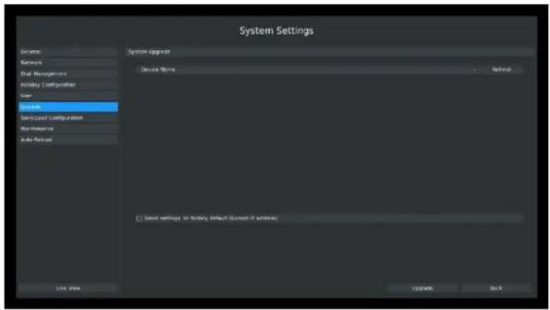
text_image
System Settings General Networks Dual Management Utility Configuration User Save Service/Control Configuration Non-Reserve Auto Release System Upgrade Save Name Save Save Settings in history default (Select if address) Load View Upgrade BackF-3.8.20
Step2. Search for device, and select the .bin file.

text_image
System Settings General Network Disk Management Host/Host Configuration User Network Server/Server Configuration Maintenance Auto Web System Upgrade Device Name USB CMS Name Value Pilot Primary Workload 12-May 2007 18:56:21 12-May 2007 18:56:24 12-May 2007 18:56:24 12-May 2007 18:56:24 12-May 2007 18:56:24 12-May 2007 18:56:24 12-May 2007 18:56:24 12-May 2007.11.03.17.17.17.17.17.17.17.17.17.17.17.17.17.17.17.17.17.17.17.17.17.17.17.17.17.17.17.17.17.17.17.17.17.17 Microsoft Windows Factor 22 May 2007 22:03:33 Project3 Factor 24 May 2007 23:03:33 System Volume Information Factor 13 May 2007 23:47:40 System IP 2 KBB IP to 27 May 2007 01:33:39 Reset settings, its factory default (Except IP address) User View Options HelpF-3.8.21
Step3. Click [Upgrade] button to confirm the upgrade.
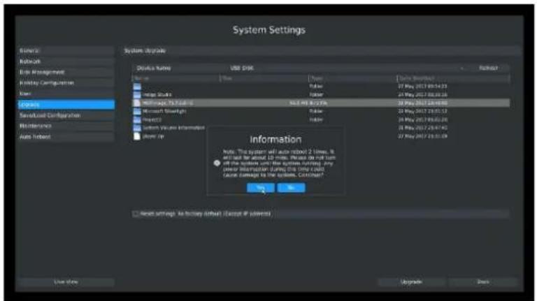
text_image
System Settings Source: Kaboon File Management Fiduciary Configuration User Systems Severized Configuration Maintenance Auto Interface System upgrade Details Name USB PRICE Name Type Date: March 2017 Time: 09:54:31 27 May 2017 08:30:16 Image Study Title 27 May 2017 08:30:16 Settings to Scale Microsoft Spotlight Title 27 May 2017 08:30:16 System Volume Information Player/Up Information Note: The system will use robot 2 lines. It will use the about 10 lines. Please do not turn all their systems using Kathine Software, any other information during this time could cause damage to the system. Continue? OK Cancel ■ Reset settings to continue default / Cancel if defaultsF-3.8.22
Note:
The system will auto reboot after confirming upgrade.
3.8.7 Save/Load Configuration
3.8.7.1 Backup/Restore
Your NVR supports backup and restore configuration.
Step1: Click Main Menu → System → Save/Load Configuration → Backup/Restore.
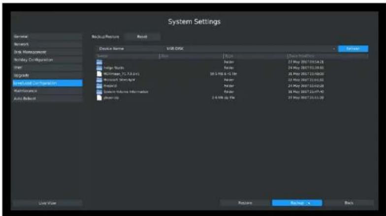
text_image
System Settings System Network Disk Management Holiday Configuration Other Upgrade Initiated Configuration Maintenance Auto Release Backup/Restore Result Device Name USB DISC Server Name Faster 27 May 2017.05.01 Finger Tools Faster 24 May 2017.01.08 MicroImage (73.7.0 fps) 38.5 Mb x 1.16e Finger 24 May 2017.01.08 MicroSensors Faster 24 May 2017.01.08 MicroCAD Faster 24 May 2017.01.08 System Volume Information Faster 2.4 Mb sp file 27 May 2017.01.08 Save Now Restore Help > BackF-3.8.23
Step2. Select a folder and then click [Backup] to export configuration to USB device.
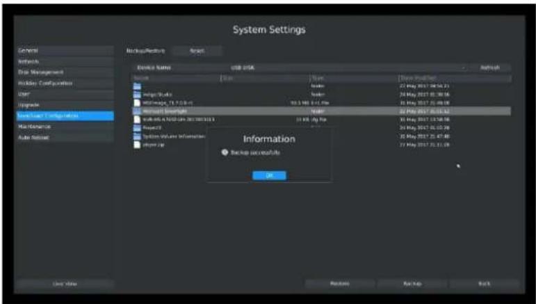
text_image
System Settings Controls Networks Data Management Holiday Configuration User Upgrade Auto Load Configuration Max Mechanics Auto Assist Device Name: USB DISK Name: [ ] [ ] [ ] [ ] [ ] [ ] [ ] [ ] [ ] [ ] [ ] [ ] [ ] [ ] [ ] [ ] [ ] [ ] [ ] [ ] [ ] [ ] [ ] [ ] [ ] [ ] [ ] [ ] [ ] [ ] [ ] [ ] [ ] [ ] [ ] [1] [2] [3] [4] [5] [6] [7] [8] [9] [10] [11] [12] [13] [14] [15] [16] [17] [18] [19] [20] [21] [22] [23] [24] [25] [26] [27] [28] [29] [30] [31] [32] [33] [34] [35] [36] [37] [38] [39] [40] [41] [42] [43] [44] [45] [46] [47] [48] [49] [50] [51] [52] [53] [54] [55] [56] [57] [58] [59] [60] [61] [62] [63] [64] [65] [66] [67] [68] [69] [70] [71] [1] [2] [3] [4] [5] [6] [7] [8] [9] [10] [11] [12] [13] [14] [15] [16] [17] [18] [19] [20] [21] [22] [23] [24] [25] [26] [27]F-3.8.24
Step3. Select a .cfg file and then click [Restore] to import configuration to your NVR.
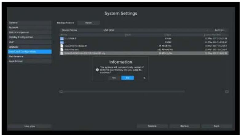
text_image
System Settings General Network User Management Holiday Configuration Color Updates System and Configuration Maintenance Auto Required Backup/Resource Reset Device Name USB Iraq Description Type: 1.0000000000000000000000000000000000000000000000000000000000000000000000000000000000000000000000000000 System 1.2.1998.6 1.2.1998.6 1.2.1998.6 1.2.1998.6 1.2.1998.6 1.2.1998.6 1.2.1998.6 1.2.1998.6 1.2.1998.6 1.2.1998.6F-3.8.25
3.8.7.2 Reset
All parameters can be reset to default settings.
Click Main Menu → System → Save/Load Configuration → Reset.
Click "yes" to confirm reset.
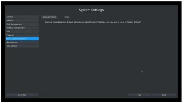
text_image
System Settings General Network Draw Management Holiday Configuration User Updates Stock and Configuration... Maintenance Auto Network Backup/Configuration Reset: Warning Reset to Factory, Default will mean all data (Except if Address). Are you sure to head to factory Default! Load View OK BackF-3.8.26
3.8.8 Auto Maintenance
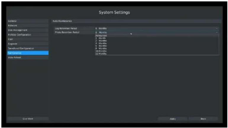
text_image
System Settings General Remove Disk Management Holiday Configuration UST Upgrade Forward Configuration Performance Auto Repair Auto Maintenance Log Remittance Period 8 Months Photo Remittance Period 5 Months Retirement 1 Month 2 Months 4 Months 5 Months 6 Months 10 Months 12 Months Live Work Apply BackF-3.8.27
You can set the Log and Photo Retention Period (from 1 to 12 months or permanently) in the Auto Maintenance interface. According to your configuration, the NVR will automatically delete your logs and photos after the retention period or permanently keep the Log and Photo.
3.8.8 Auto Reboot
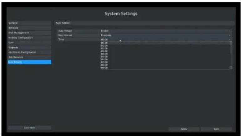
text_image
System Settings General Network Cash Management Holiday Configuration User Upgrade Service/Service Configuration Home Resource Auto Return Auto Return Auto Return Auto Return Auto Return Auto Return Auto Return Auto Return Auto Return Auto Return Auto Return Auto Return Auto Return Auto Return Auto Return Auto Return Auto Return Auto Return Auto Return Auto Return Auto Return Auto Return Auto Return Auto Return Auto Return Auto Return Auto Return Auto Return Auto Return Auto Return Auto Return Auto Return Auto Return Auto ReturnF-3.8.28
You can set day interval and time for reboot, and the NVR will reboot automatically on the time you set.
[Day Interval]: Everyday, Monday, Tuesday, Wednesday, Thursday, Friday, Saturday and Sunday.
[Time]: 00:00, 01:00, 02.00 ..... 22:00, 23:00.
3.9 Shutdown
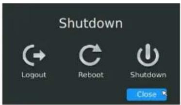
text_image
Shutdown Logout Reboot Shutdown CloseF-3.9.1
3.9.1 Logout
Click [Logout] to exit the current logon account.
3.9.2 Reboot
Click [Reboot] to restart the NVR.
3.9.3 Shutdown
Click [Shutdown] to close the NVR.
3.9.4 Close
Click [Close] to exit.
4. WEB Settings
4.1 Login
Input the user name and password.
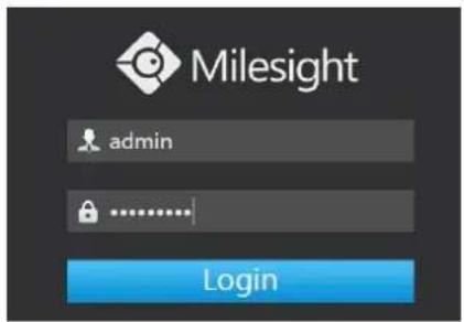
text_image
Milesight admin LoginF-4.1.1
Note:
- If the NVR firmware version out of the factory is xx.7.0.6 or above, the default user name is "admin" and the default password is "ms1234";
- If the NVR firmware is upgraded to xx.7.0.6 or above from a lower version, the default password will turn to "ms1234" after a reset, or it will keep the old default password "123456";
- If the NVR firmware version is below xx.7.0.6, the default user name is "admin" and the default password is "123456".
4.2 Live View
4.2.1 Camera List
There are multiple icons on each channel displayed in live view mode, indicating the recording and alarm status of the channel.
| Icons | Descriptions |
 | Indicates video loss |
 | Indicates motion detection alarm |
Step1: Enter Live View by clicking one window, and go for camera list.
Click to show the main stream and click to the sub stream.
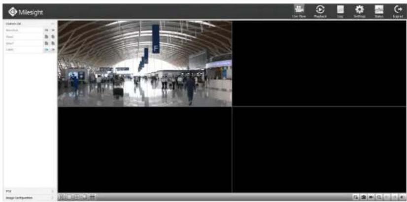
text_image
Milesight Start Menu Start Menu View Playback Play Settings Status Logic Image Configuration MilesightF-4.1.2
Quick Operation

| Icon | Description | Icon | Description | Icon | description |
 | Stop All Live View |  | Start All Live View |  | Snapshot by manually |
 | Front Page |  | Next Page |  | Sound off/on |
 | Full Screen |  | Window 1 |  | Window 4 |
 | Window 8 |  | Window 9 |
4.2.2 Play View
Click Live View→ Camera List. Choose the View1 or View2 to play;
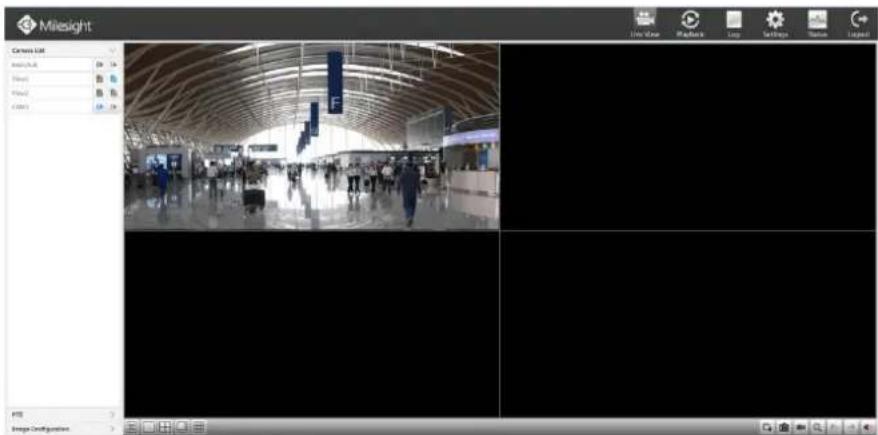
text_image
Milesight Canvas List AutoBook View View2 CCTS File View MacBook Loop Settings Status Legend Image ConfigurationF-4.1.3
4.2.3 PTZ
Click Live View→PTZ
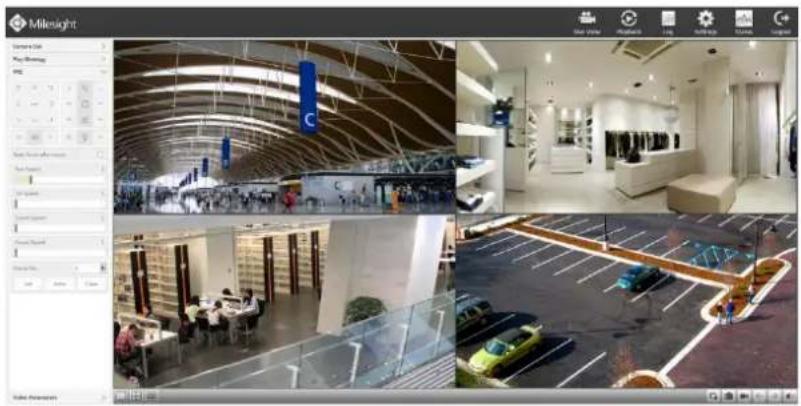
natural_image
Composite image showing four interior views of a modern retail or exhibition space: a large curved ceiling, a modern service hall with seating and signage, a parking lot with cars, and a close-up of the interior (no visible text or symbols)F-4.1.4
4.2.4 Video Parameters
Click Live View→ Video Parameters
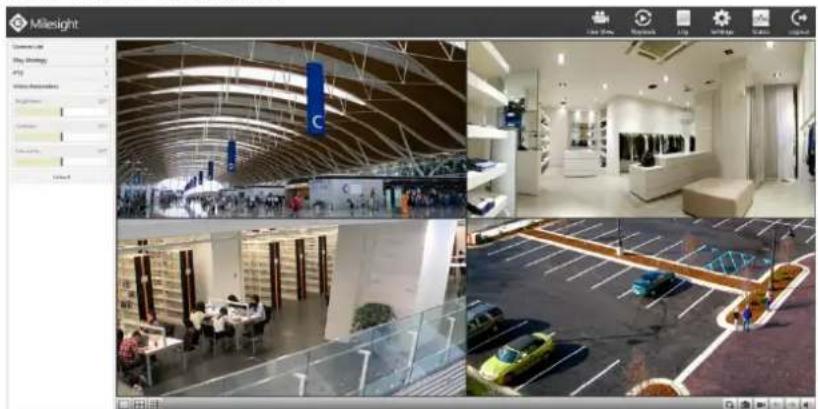
natural_image
Composite image showing four interior views of a modern building: ceiling, interior space with service counters, and parking lot (no visible text or symbols)F-4.1.5
4.3 Playback
To play and backup the recorded files.
4.3.1 Playback
It can support playback according to recorded time. Play recorded files in specified time period.
Step1. Click Playback→

(shown in F-4.3.1).
Step2. Select a desired channel and date.
Select playback layout and channel. Click the date in red when there are recorded files of the selected channels, the record type with recording data will be show as below, and then click
to playback.
Note:
The day with a blue mark has recording files; please select the date in red to playback.
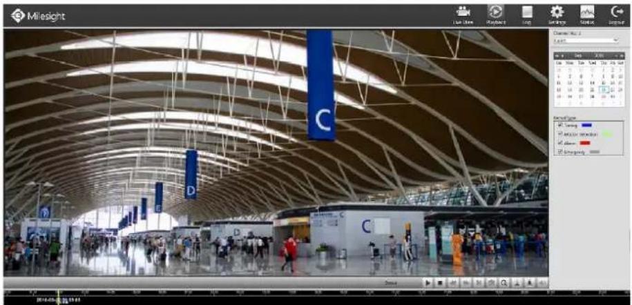
text_image
Milesight C D E 2016-05-24 星期四F-4.3.1
Video Playback Tool Bar Description

text_image
20:00:00 Emergency Timing Motion Detection AlarmsThe tool bar can display multi-event record. It shows that in this record period what kind of event has happened. The symbolic meaning of each color is shown below:
Blue—Timing Green --- Motion
Red --- Alarm Grey --- Emergency
And take this bar above as an example, it means in this recording period there are motion and timing event which have triggered.
| Button | Description | Button | Description | Button | Description | Button | Description |
 | Rewind |  | Stop |  | Play |  | Pause |
 | Reverse Step |  | Forward Step |  | Fast Backward |  | Fast Forward |
 | Timeline Cutting |  | Timeline Cut Off |  | Audio On |  | Audio Off |
 | Snapshot |  | Timeline |  | Playback Position |
4.3.2 Video Files Backup
Recorded files can be cut and backed up from WEB.
Step1. In playback interface, select the date and time to playback
text_image
Milesight Live View Playback Help Settings Window Legend Current Time 1 Up Start New Start New Next Up End Stop Start Stop Next Stop Up Start Stop Next Stop Next Stop Up End Stop Next Stop Next Stop Up Start Stop Next Stop Next Stop Up End Stop Next Stop Next Stop Up Start Stop Next Stop Next Stop Up End Stop Next Stop Next Stop Up Start Stop Next Stop Next Stop Up End Stop Next Stop Next Stop Up Start Stop Next Stop Next Stop Up End Stop Next Stop Next Stop Up Start Stop Next Stop Next Stop Up End Stop Next Stop Next Stop Up Start Stop Next Stop Next Stop Up End Stop Next Stop Next StopF-4.3.2
Step2. Select Recorded files for Backup.
Select the channel and date you want to backup, then select the start time at time line and click

it will change into which means cut begins.
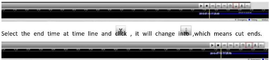
text_image
Select the end time at time line and click , it will change into ,which means cut ends.Then backup files can be found the files path set before.
Step3. Backup the files
Click the button and choose the path to save the file

text_image
2018-07-19 20:30:22 Emergency Timing Motion Detection Alarm4.3.3 Picture Files Backup
Step1. Click Settings → Local Configuration
Choose Playback Picture Path.
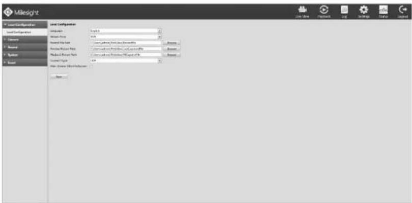
text_image
Milesight Local Configuration Local Configuration Parameters Parameters Parameters Name Parameters Name Parameters Name Parameters Name Parameters Name Parameters Name Parameters Name Parameters Name Parameters Name Parameters Name Parameters Name Parameters Name Parameters Name Parameters Name Parameters Name Parameters Name Parameters Name Parameters Name Parameters Name Parameters Name Parameters Name Parameters Name Parameters Name Parameters Name Parameters Name Parameters Name Parameters Name Parameters Name Parameters Name Parameters Name Parameters Name Parameters Name Parameters Name Parameters NameF-4.3.3
Step2. Pause first when you want backup a special scene during video playback.
Step3. Click to save picture. Then backup picture can be found the files path set before.
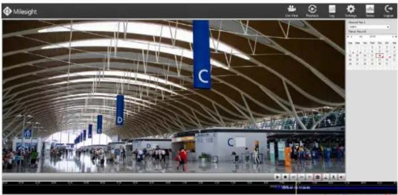
text_image
Milesight Live Home Passwd Log Logistic Version Legend Show Record Date: 2019-04-23 C D CF-4.3.4
4.4 Logs
In Log interface, you can check, search and save important logs. By selecting the Main Type, Sub Type, Start Time and End Time which can narrow down the scale of logs, you can search for logs that you need and then save them locally.
Click Logs → Main Type → Sub Type → Start Time → End Time → Search → Save
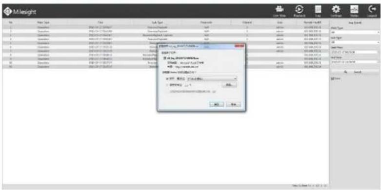
text_image
Milesight File Type Name Size Material Description Date Spread Date File Type 1 2 3 4 5 6 7 8 9 10 11 12 13 14 15 16 17 18 19 20 21 22 23 24 25 26 27 28 29 30 31 32 33 34 35 36 37 38 39 40 41 42 43 44 45 46 47 48 49 50 51 52 53 54 55 56 57 58 59 60 61 62 63 64 65 66 67 68 69 70 71 72 73 74 75 76 77 78 79 80 81 82 83 84 85 86 87 88 89 90 91 92 93 94 95 96 97 98 99 100F-4.4.1
4.5 Settings
4.5.1 Local Configuration
Step1. Click Settings→ Local Configuration.
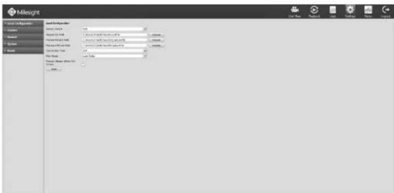
text_image
Milesight Load Expendizer Load Expendizer Load Expendizer Load Expendizer Load Expendizer Load Expendizer Load Expendizer Load Expendizer Load Expendizer Load Expendizer Load Expendizer Load Expendizer Load Expendizer Load Expendizer Load Expendizer Load Expendizer Load Expendizer Load Expendizer Load Expendizer Load Expendizer Load Expendizen Load Expendizen Load Expendizen Load Expendizen Load Expendizen Load Expendizen Load Expendizen Load Expendizen Load Expendizen Load Expendizen Load Expendizen Load Expendizen Load Expendizen Load Expendizen Load Expendizen Load Expendizen Load Expendizen Load Expendizen Load Expendizen Load Expendizen Load ExpendenF-4.5.1
Step2. Set record file path, preview picture path and playback file path.
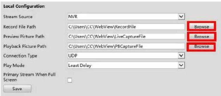
text_image
Local Configuration Stream Source NVR Record File Path C:\Users\CC\WebView\RecordFile Browse Preview Picture Path C:\Users\CC\WebView\LiveCaptureFile Browse Playback Picture Path C:\Users\CC\WebView\PBCaptureFile Browse Connection Type UDP Play Mode Least Delay Primary Stream When Full Screen SaveF-4.5.2
Step3. Set connection type and play mode, then save configuration.
4.5.2 Camera
Before configuration, please ensure that the IP device is connected to the same network as your NVR and that the network setting for your NVR is properly setup.
4.5.2.1 Camera Management
Step1. Enter Camera Management by Click Settings → Camera.
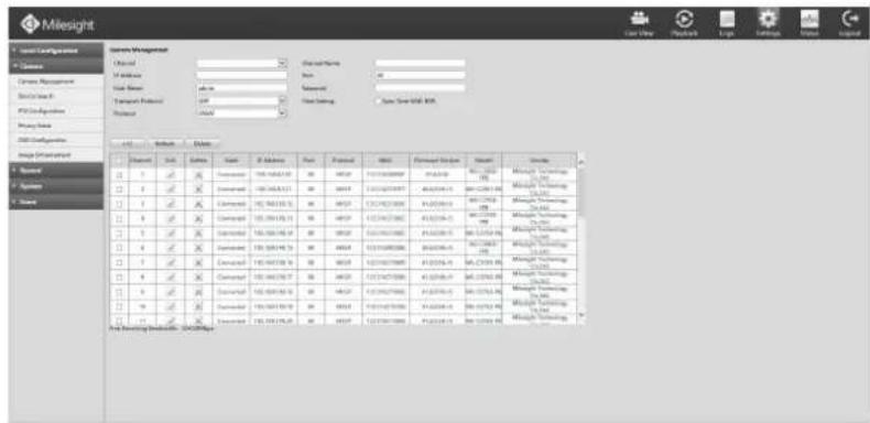
text_image
Milesight System Management Channel Access Data Source Transport Protocol Protocol Status Description Name Parameters Parameters Parameters Parameters Parameters Parameters Parameters Parameters Parameters Parameters Parameters Parameters Parameters Parameters Parameters Parameters Parameters Parameters Parameters Parameters Parameters Parameters Parameters Parameters Parameters Parameters Parameters Parameters Parameters Parameters Parameters Parameters Parameters Parameters Parameters Parameters Parameters Parameters Parameters Parameters Parameters Parameters Parameters Parameters Parameters Parameters Parameters Parameters Parameters Parameters Components Settings Settings Settings Settings Settings Settings Settings Settings Settings Settings Settings Settings Settings Settings Settings Settings Settings Settings Settings Settings Settings Settings Settings Settings Settings Settings Settings Settings Settings Settings Settings Settings Settings Settings Settings Settings Settings Settings Settings Settings Settings Settings Settings Settings Settings Settings Settings Settings Settings Settings InstructionsF-4.5.3
Step2. Add IP Channel.
Method1. Add IP Channel in device search interface
- Click Settings → Camera → Device Search.
text_image
Mileight Local Configuration - Servers Server Management Server Search FTP Configurations Proxy Search Host & Manager Host Software Search Security Parameters SearchF-4.5.4
- Click [Search] button to quickly search the IP devices that support ONVIF at the same network segment with NVR.
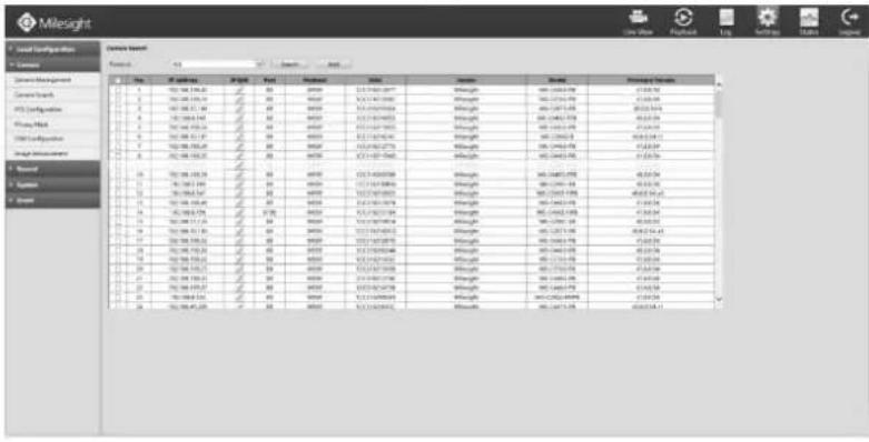
text_image
Milesight Local Settings Office Current Version Name: 123 File Edit View Help Tools Help Current Settings Current Tech FTP Configulator Playoff Pack USB Regularizer Height dimensions Normal System Normal 1. 100.000.000.00 2. 100.000.000.00 3. 100.000.000.00 4. 100.000.000.00 5. 100.000.000.00 6. 100.000.000.00 7. 100.000.000.00 8. 100.000.000.00 9. 100.000.000.00 10. 100.000.000.00 11. 100.000.000.00 12. 100.000.000.00 13. 100.000.000.00 14. 100.000.000.00 15. 100.000.000.00 16. 100.000.000.00 17. 100.000.000.00 18. 100.000.000.00 19. 100.000.000.00 20. 100.000.000.00 21. 100.000.005 22. 155.55555555 23. 155.55555555 24. 155.55555555 25. 155.55555555 26. 155.55555555 27. 155.55555555 28. 155.55555555 29. 155.55555555 30. 155.55555555 31. 155.55555555 32. 155.55555555 33. 155.55555555 34. 155.55555555 35. 155.55555555 36. 155.55555555 37. 155.55555555 38. 155.55555555 39. 155.55555555 40. 155.55555555 41. 155.555F-4.5.5
- Click the channel, click [Add] button, input password and click [OK] button to finish or click [Cancel] button to cancel.
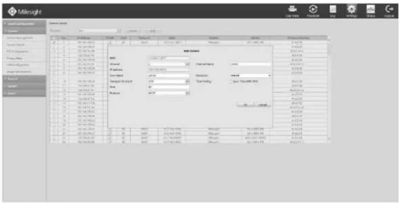
text_image
Milesight Name: Milelight Description: Name: Milelight Description: Milelight Name: Milelight Description: Milelight Name: Milelight Description: Milelight Name: Milelight Description: Milelight Name: Milelight Description: Milelight Name: Milelight Description: Milelight Name: Milelight Description: Milelight Name: Milelight Description: Milelight Name: Milelight Description: Milelight Name: Milelight Description: Milelight Name: Milelight Description: MilelightF-4.5.6
- Or you can Check ☑ to bulk adding the network cameras If they are with the same password, and you can choose TCP or UDP transport protocol for bulk adding. Click [OK] to finish bulk adding.
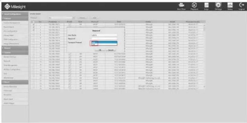
text_image
Milesight Data Transfer Parameters Report 3 Transport Policy Data Transfer Report 3 Transport Policy Data Transfer Report 3 Transport Policy Data Transfer Report 3 Transport Policy Data Transfer Report 3 Transport Policy Data Transfer Report 3 Transport Policy Data Transfer Report 3 Transport Policy Data Transfer Report 3 Transport Policy Data Transfer Report 3 Transport Policy Data Transfer Report 3 Transport Policy Data Transfer Report 3 Transport Policy Data Transport Report 3 Transport Policy Data Transport Report 3 Transport Policy Data Transport Report 3 Transport Policy Data Transport Report 3 Transport Policy Data Transport Report 3 Transport Policy Data Transport Report 3 Transport Policy Data Transport Report 3 Transport Policy Data Transport Report 3 Transport Policy Data Transport Report 3 Transport Policy Data Transport Report 3 Transport Policy Data Transportation Report 3 Transport Policy Data Transportation Report 3 Transport Policy Data Transportation Report 3 Transport Policy Data Transportation Report 3 Transport Policy Data Transportation Report 3 Transport Policy Data Transportation Report 3 Transport Policy Data Transportation Report 3 Transport Policy Data Transportation Report 3 Transport Policy Data Transportation Report 3 Transport Policy Data Transportation Report 3 Transport Policy Data Transport Report 3 Transport Policy Data Transport Report 3 Transport Policy Data Transport Report 3 Transport Policy Data Transport Report 3 Transport Policy Data Transport Report 3 Transport PolicyF-4.5.7
Method2. Add IP Channel in camera management interface
- Click Settings→Camera → Camera Management
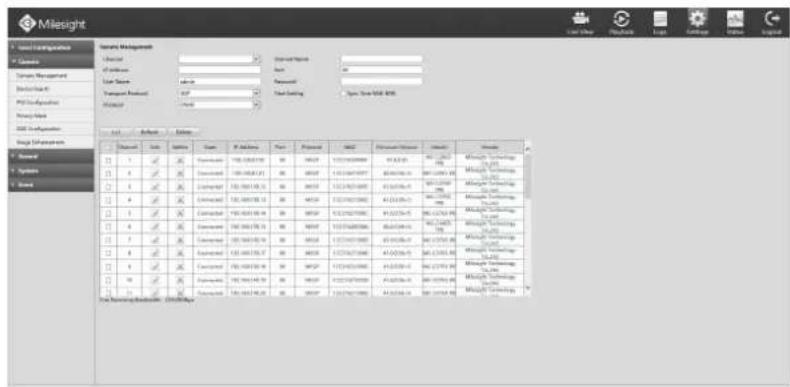
text_image
Milesight System Management Operator: 20 Standard Name: Date: 01 Load Name: None Password: Open Time SCR &MS Transport Protocol: CDF Start Setting Capacity: 5000000000000000000000000000000000000000000000000000000000000000000000000000000000000000000000000 End Options Channel | Sub | Options | Type | IP Address | Port | Protocol | MSU | Performance Options | Update | Summary 1 1 2 3 4 5 6 7 8 9 10 11 12 13 14 15 16 17 18 19 20 21 22 23 24 25 26 27 28 29 30 31 32 33 34 35 36 37 38 39 40 41 42 43 44 45 46 47 48 49 50 51 52 53 54 55 56 57 58 59 60 61 62 63 64 65 66 67 68 69 70 71 72 73 74 75 76 77 78 79 80 81 82 83 84 85 86 87 88 89 90 91 92 93 94 95 96 97 98 99 100 1.1.1.2.3.4.5.6.7.8.9.10.11.12.13.14.15.16.17.18.19.20.21.22.23.24.25.26.27.28.29.30.31.32.33.34.35.36.37.38.39.40.41.42.43.44.45.46.47.48.49.50.51.52.53.54.55.56.57.58.59.60.61.62.63.64.65.66.67.68.69.70.71.72.73.74.75.76.77.78.79.80.81.82.83.84.85.86.87.88.89.90.91.92.93.94.95.96.97.98.99.10.11.F-4.5.8
- Select idle channel then input complete information, click [Add] button.
There are three protocols available for camera connection:
- ONVIF: You can add any IP cameras with ONVIF protocols if you selected this protocol. Details are shown in F-4.5.9;
- RTSP: You can add any IP cameras with RTSP protocol streams (Port: 554). You need to input complete resource path of the IP camera to add it. Take Milesight device for example, the resource path of main stream is "rtsp://IP:port/main" and of second stream is "rtsp://IP:port/sub". Details are shown in F-4.5.10;
- MSSP: You can add Milesight cameras which are in the same LAN by select this protocol. Details are shown in F-4.5.11.
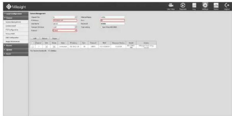
text_image
Milkslight Database Management Address: 1234000000 File Address: 1234000000 File Name: 1234000000 Data type: Microsoft Excel Data source: Microsoft Excel Data type: Microsoft Excel Data type: Microsoft Excel Data source: Microsoft Excel Data type: Microsoft Excel Data source: Microsoft Excel Data source: Microsoft Excel Data source: Microsoft Excel Data source: Microsoft Excel Data source: Microsoft Excel Data source: Microsoft Excel Data source: Microsoft Excel Data source: Microsoft Excel Data source: Microsoft Excel Data source: Microsoft Excel Data source: Microsoft Excel Data source: Microsoft Excel Data source: Microsoft Excel Data source: Microsoft Excel Data source: Microsoft Excel Data source: Microsoft Excel Data source: Microsoft ExcelF-4.5.9
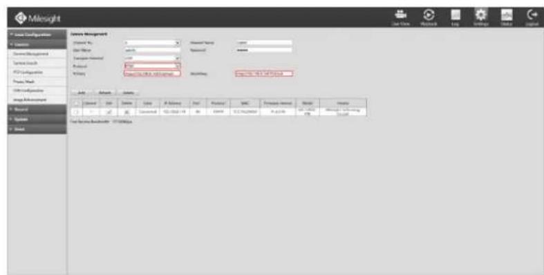
text_image
Milelight Device Management Name: No Type: 100% Description: Current Status System Status CPU Subgroups Process Mode Device Configuration Record Options Data Storage BackUp - 17.0000000000000000000000000000000000000000000000000000000000000000000000000000000000000000000000000000 Address Name Type Description Current Post Postset MAC Proprietary Interest Name History Data Storage BackUp - 17.00000000000000000 12.3.14.28.28.28.28.28.28.28.28.28.28.28.28.28.28.28.28.28.28.28.28.28.28.28.28.28.28.28.28.28.28.28.28.28.28 Test Data Storage BackUp - 17.0000000F-4.5.10
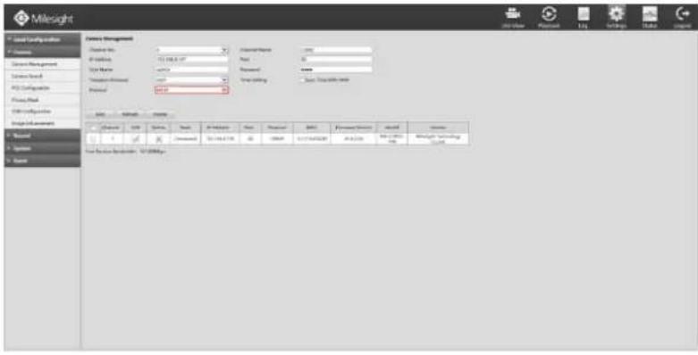
text_image
Milesight Service Management Customer Name: 0 Customer Address: 12.108.6.17 Product Name: Product Type: Transportation Processed: Transportation Method: Transportation Time: 45.00 Transportation Time: 45.00 Customer Name: Customer Address: 12.108.6.17 Customer Name: Customer Address: 12.108.6.17 Customer Name: Customer Address: 12.108.6.17 Customer Name: Customer Address: 12.108.6.17 Customer Name: Customer Address: 12.108.6.17 Customer Name: Customer Address: 12.108.6.16 Customer Name: Customer Address: 12.108.6.16 Customer Name: Customer Address: 12.108.6.16 Customer Name: Customer Address: 12.108.6.16 Customer Name: Customer Address: 12.108.6.16 Customer Name: Customer Address: 12.108.6.15 Customer Name: Customer Address: 12.108.6.15 Customer Name: Customer Address: 12.108.6.15 Customer Name: Customer Address: 12.108.6.15 Customer Name: Customer Address: 12.108.6.15 Customer Name: Customer Address: 12.108.6.14 Customer Name: Customer Address: 12.108.6.14 Customer Name: Customer Address: 12.108.6.14 Customer Name: Customer Address: 12.108.6.14 Customer Name: Customer Address: 12.108.6.13 Customer Name: Customer Address: 12.108.6.13 Customer Name: Customer Address: 12.108.6.13 Customer Name: Customer Address: 12.108.6.13 Customer Name: Customer Address: 12.108.6.12 Customer Name: Customer Address: 12.108.6.12 Customer Name: Customer Address: 12.108.6.12 Customer Name: Customer Address: 12.108.6.12 Customer Name: Customer Address: 12.108.6.12 Customer Name: Customer Address: 12.108.6.11 Customer Name: Customer Address: 12.108.6.11 Customer Name: Customer Address: 12.108.6.11 Customer Name: Customer Address: 12.108.6.10 Customer Name: Customer Address: 12.108.6.10 Customer Name: Customer Address: 12.108.6.9 Customer Name: Customer Address: 12.108.6.9 Customer Name: Customer Address: 12.108.6.9 Customer Name: Customer Address: 12.108.6.9 Customer Name: Customer Address: 12.108.6.9 Customer Name: Customer Address: 12.108.6. Customer Name: Customer Address: 12.108.6. Customer Name: Customer Address: 12.108.6. Customer Name: Customer Address: 12.108.6. Customer Name: Customer Address: 12.108.6. Customer Name: Customer Address: 12.108. Customer Name: Customer Address: 12.108. Customer Name: Customer Address: 12.108. Customer Name: Customer Address: 12.108. Customer Name: Customer Address: 12.108. Customer Name: Customer Address: 12.108. Customer Name: Customer Address: 12.108. Customer Name: Customer Address: 377-379-379 Customer Name: Customer Address: 377-379-379 Customer Name: Customer Address: 377-379-379 Customer Name: Customer Address: 377-379-379 Customer Name: Customer Address: 377-379-379 Customer Name: Customer Address: 377-379-379F-4.5.11
Step3. Check the connection status.
After adding the IP channels, click [Refresh] button, then [connected] appears under[status]. If it doesn't appear, you need to check if the network is connected or whether the user name, password is correct or not.
| Channel | Edit | Delete | State | IP Address | Port | Protocol | MAC | Vendor | Model |
| 1 | ✓ | ✘ | Connected | 192.168.200.55 | 80 | ONVIF | 1CC31611030B | Milesight Technology Co.,Ltd. | MS-C3263 |
| 2 | ✓ | ✘ | Connected | 192.168.200.53 | 80 | ONVIF | 1CC31611038A | Milesight Technology Co.,Ltd. | MS-C3263 |
| 3 | ✓ | ✘ | Connected | 192.168.200.57 | 80 | ONVIF | 1CC3161109EA | Milesight Technology Co.,Ltd. | MS-C3263 |
| 4 | ✓ | ✘ | Connected | 192.168.200.50 | 80 | ONVIF | 1CC316110369 | Milesight Technology Co.,Ltd. | MS-C3263 |
F-4.5.12
Step4. Configure IP Channel
After successfully adding the channel, click 📄 to re-edit the channel info, address, and password, etc.
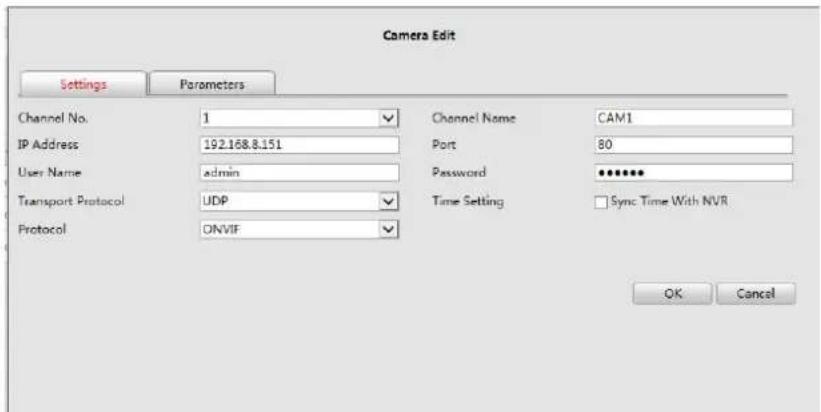
text_image
Camera Edit Settings Parameters Channel No. 1 ✓ Channel Name CAM1 IP Address 192.168.8.151 Port 80 User Name adults Password **** Transport Protocol UDP ✓ Time Setting □ Sync Time With NVR Protocol ONVIF OK CancelF-4.5.13
Select [Parameters] page to re-edit this channel parameters. Click [Save] to save the configuration
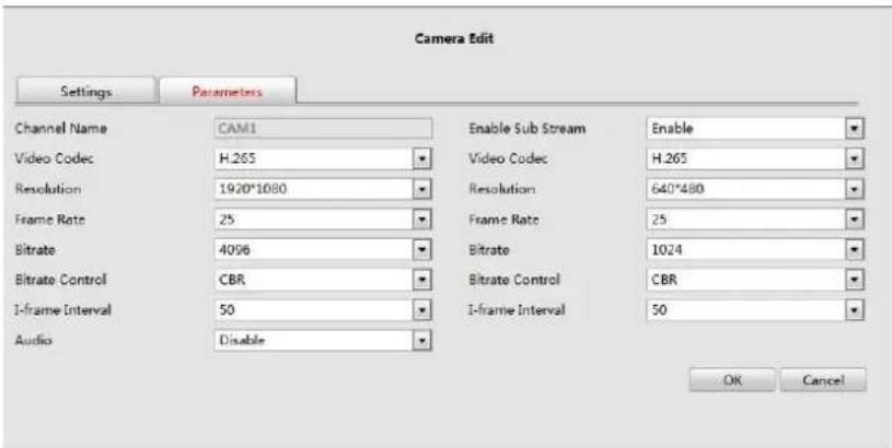
text_image
Camera Edit Settings Parameters Channel Name CAM1 Enable Sub Stream Enable Video Codec H.265 Video Codec H.265 Resolution 1920*1080 Resolution 640*480 Frame Rate 25 Frame Rate 25 Bitrate 4096 Bitrate 1024 Bitrate Control CBR Bitrate Control CBR 1-frame Interval 50 1-frame Interval 50 Audio Disable OK CancelF-4.5.14
You can delete this channel by clicking, or you can select multiple devices and then click
Delete
to delete.
| Channel | Edit | Delete | State | IP Address | Port | Protocol | MAC | Vendor | Model |
| 1 | Connected | 192.168.200.55 | 80 | ONVIF | 1CC3161103DB | Milesight Technology Co.,Ltd. | MS-C3263 | ||
| 2 | Connected | 192.168.200.53 | 80 | ONVIF | 1CC31611038A | Milesight Technology Co.,Ltd. | MS-C3263 | ||
| 3 | Connected | 192.168.200.57 | 80 | ONVIF | 1CC3161103EA | Milesight Technology Co.,Ltd. | MS-C3263 | ||
| 4 | Connected | 192.168.200.59 | 80 | ONVIF | 1CC316110369 | Milesight Technology Co.,Ltd. | MS-C3263 |
Note:
The user name and password entered here are the default user name and password. The management port is 80 and the default Transport protocol is UDP.
text_image
Mildeight Data Management Name: Mildeight File Edit View Help Parameters: 1234000000000000000000000000000000000000000000000000000000000000000000000000000000000000000000000000000 Source: Mildeight Results: 123400000000000000 Date: May 25, 26, 27, 28, 29, 30, 31, 32, 33, 34, 35, 36, 37, 38, 39, 40, 41, 42, 43, 44, 45, 46, 47, 48, 49, 50, 51, 52, 53, 54, 55, 56, 57, 58, 59, 60, 61, 62, 63, 64, 65, 66, 67, 68, 69, 70, 71, 72, 73, 74, 75, 76, 77, 78, 79, 80, 81, 82, 83, 84, 85, 86, 87, 88, 89, 90, 91, 92, 93, 94, 95, 96, 97, 98, 99, 100 Source: Mildeight Results: May 25, 26, 27, 28, 29, 30, 31, 32, 33, 34, 35, 36, 37, 38, 39, 40, 41, 42, 43, 44, 45, 46, 47, 48, 51, 52, 53, 54, 55, 56, 57, 58, 59, 61, 62, 63, 64, 65, 66, 67, 68, 69, 71, 72, 73, 74, 75, 76, 77, 78, 79, 81, 82, 83, 84, 85, 86, 87, 88, 89, 91, 92, 93, 94, 95, 96, 97, 98, 99 Source: Mildeight Results: May 25, 26, 27, 28-29-29-29-29-29-29-29-29-29-29-29-29-29-29-29-29-29-29-29-29-29-29-29-29-29-29-29-29-29-29-29-29-29-29F-4.5.15
4.5.2.2 Device Search
Step1. Click Settings → Camera → Device Search.
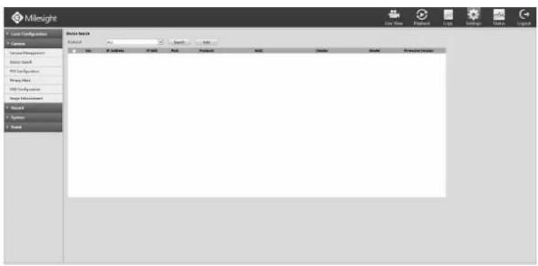
text_image
Milebright Local Configuration Camera Server Management Device Start VCS Configuration String Pitch VCS Configuration Design Environment Mouse Syntax Text Drive Base Material File Edit View Paste Links Settings Tools LayoutF-4.5.16
Step2. Choose [All], then click [search] to quickly search the IP devices that support ONVIF at the same LAN with NVR; switch Protocol into [ONVIF] to search the IP devices that support ONVIF at the same network segment with NVR, or switch Protocol into [MILESIGHT] to search the IP devices that support MILESIGHT at the same LAN with NVR.
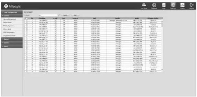
text_image
Milesight File Edit View Name: 123 File Edit View Insert Tools Help Tools Help Tools Help Tools Help Tools Help Tools Help Tools Help Tools Help Tools Help Tools Help Tools Help Tools Help Tools Help Tools Help Tools Help Tools Help Tools Help Tools Help Tools Help Tools Help Tools Help Tools Help Tools Help Tools Help Tools Help Tools Help Tools Help Tools Help Tools Help Tools Help Tools Help Tools Help Tools Help Tools Help Tools Help Tools Help Tools Help Tools Help Tools Help Tools Help Tools Help Tools Help Tools Help Tools Help Tools Help Tools Help Tools Help Tools Help Tools Help Tools Help Tools help tools help tools help tools help tools help tools help tools help tools help tools help tools help tools help tools help tools help tools help tools help tools help tools help tools help tools help tools help tools help tools help tools help tools help tools help tools help tools help tools help tools help tools help tools help tools help tools help tools help tools help tools help tools help tools help tools help tools help tools help tools help tools help tools help tools help tools help tools help tools help tools help tools help tools help teams help teams help teams help teams help teams help teams help teams help teams help teams help teams help teams help teams help teams help teams help teams help teams help teams help teams help teams help teams help teams help teams help teams help teams help teams help teams help teams help teams help teams help teams help teams help teams help teams help teams help teams help teams help teams help teams help teams help teams help teams help teams help teams help teams help teams help teams help teams help teams help teams help teams help groups help groups help groups help groups help groups help groups help groups help groups help groups help groups help groups help groups help groups help groups help groups help groups help groups help groups help groups help groups help groups help groups help groups help groups help groups help groups help groups help groups help groups help groups help groups help groups help groups help groups help groups help groups help groups help groups help groups help groups help groups help groups help groups help groups help groups help groups help groups help groups help groups help groups help teams help teams help teams help teams help teams help teams help teams help teams help teams help teams help teams help teams help teams help teams help teams help teams help teams help teams help teams help teams helps to support the team's best performance. For all these best performances, the best performance is best for the best performance. The best performance is best for the best performance. The best performance is best for the best performance. The best performance is best for the best performance. The best performance is best for the best performance. The best performance is best for the best performance. The best performance is best for the best performance. The best performance is best for the best performance. The best performance is best for the best performance. The best performance is best for the best performance. The best performance is best for the best performance.F-4.5.17
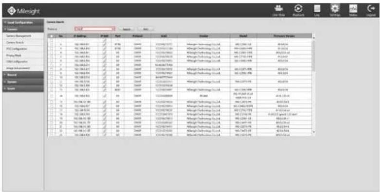
text_image
Milesight Local Designator 01 Design Current Management Current Node: 1. X: 100,000,000 2. Y: 100,000,000 3. Z: 100,000,000 4. AA: 100,000,000 5. AB: 100,000,000 6. AC: 100,000,000 7. AD: 100,000,000 8. AE: 100,000,000 9. AF: 100,000,000 10. AG: 100,000,000 11. AH: 100,000,000 12. AI: 100,000,000 13. AJ: 100,000,000 14. AK: 100,000,000 15. AL: 100,000,000 16. AM: 100,000,000 17. AN: 100,000,000 18. AO: 100,000,000 19. AP: 100,000,000 20. AQ: 100,000,000 21. AR: 100,000,000 22. AS: 100,000,000 23. AT: 100,000,000 24. AU: 155,555,555 25. AV: 155,555,555 26. AW: 155,555,555 27. AX: 155,555,555 28. AY: 155,555,555 29. AZ: 155,555,555 30. BA: 155,555,555 31. CA: 155,555,555 32. CB: 155,555,555 33. CC: 155,555,555 34. DD: 155,555,555 35. EY: 155,555,555 36. FZ: 155,555,555 37. GA: 155,555,555 38. HJ: 155,555,555 39. IY: 155,555,555 40. JY: 155,555,555 41. KX: 155,555,555 42. LKX: 155,555,555 43. MZ: 155,555,555 44. NQ: 166,666,666 45. OQ: 166,666,666 46. PQ: 166,666,666 47. QZ: 166,666,666 48. RZ: 166,666,666 49. SIC: 166,666,666 50. TSC: 166,666,666 51. UQ: 166,666,666 52. VZ: 166,666,666 53. WZ: 166,666,666 54. XZ: 166,666,666 55. YZ: 166,666,666 56. ZQ: 177,777,777 57. AAZ: 177,777,777 58. ZBZ: 177,777,777 59. ZCZ: 177,777,777 60. ZDZ: 177,777,777 61. ZEZZ: 177,777,777 62. ZFZZ: 177,777,777 63. ZGZZ: 177,777,777 64. ZHZZ: 177,777,777 65. ZIZZZ: 177,777,777 66. ZJZZZ: 177,777,777 67. ZKZZZ: 177,777,777 68. ZLZZZ: 177,777,777 69. ZMZZZ: 177,777,777 70. ZNZZZ: 177,777,777 71. ZOZZZ: 182,222,222 TENUELE NAME: Current Node: X: X=X=X=X=X=X=X=X=X=X=X=X=X=X=X=X=X=X=X=X=X=X=X=X=X=X=X=X=X=X=X=X=X=X=X=X=X=X=X=X=X=X=X=X=X=X=X=X=X=X=X= X, Y: Y=Y=Y=Y=Y=Y=Y=Y=Y=Y=Y=Y=Y=Y=Y=Y=Y=Y=Y=Y=Y=Y=Y=Y=Y=Y=Y=Y=Y=Y=Y=Y=Y=Y=Y=Y=Y=Y=Y=Y=Y=Y=Y=Y=Y=Y=Y=Y=Y=Y=Y= Y, A: B: C: D: E: F: G: H: I: J: K: L: M: N: O: P: Q: R: S: T: U: V: W: X: Y: Z: A-A:B:C:E:F(G) : (A+A+B+C) : (B+A+C) : (C+D) : (D+E) : (E+D) : (F+D) : (G+E) : (H+F) : (I+G) : (J+H) : (K+I) : (L+J) : (M+K) : (N+L) : (O+M) : (P+M) : (Q+N) : (R+O) : (S+P) : (T+Q) : (U+V) : (V+W) : (W+X) : (X+Y) : (Z) A-B:A:C:E(F) : (A+A+B+C) : (B+A+C) : (C+D) : (D+E) : (E+D) : (F+D) : (G+E) : (H+F) : (I+G) : (J+H) : (K+I) : (L+J) : (M+K) : (N+L) : (O+M) : (R+O) : (S+P) : (T+Q) : (U+V) : (V+W) : (W+X) : (X+Y) : (Z) A-C:A:C:E(F) : (A+A+B+C) : (B+A+C) : (C+D) : (D+E) : (E+D) : (F+D) : (G+E) : (H+F) : (I+G) : (J+H) : (K+I) : (L+J) : (M+K) : (N+L) : (O+L) : (P+M) : (Q+N) : (R+O) : (S+P) : (T+Q) : (U+V) : (V+W) : (W+X) : (X+Y) : (Z) A-D:A:C:E(F) : (A+A+B+C) : (B+A+C) : (C+D) : (D+E) : (E+D) : (F+D) : (G+E) : (H+F) : (I+G) : (J+H) : (K+I) : (L+J) : (M+K) : (N+L) : (O+I) : (P+M) : (R+O) : (S+P) : (T+Q) : (U+V) : (V+W) : (W+X) : (X+Y) : (Z) A-E:A:C:E(F) : (A+A+B+C) : (B+A+C) : (C+D) : (D+E) : (E+D) : (F+D) : (G+E) : (H+F) : (I+G) : (J+H) : (K+I) : (L+J) : (M+K) : (N+L) : (O+l) .F-4.5.18
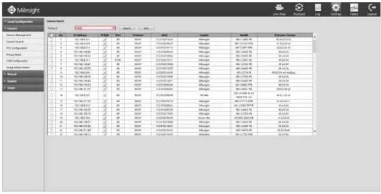
text_image
Milesight Local Configuration Name: Mile Insight File Edit View Insert Help Help Help Help Help Help Help Help Help Help Help Help Help Help Help Help Help Help Help Help Help Help Help Help Help Help Help Help Help Help Help Help Help Help Help Help Help Help Help Help Help Help Help Help Help Help Help Help Help Help Help Help Help Help Help Help Help Help Help Help Help Help Help Help Help Help Help Help Help Help Help Help Help Help Help Help Help Help Help Help Help Help Help Help Help Help Help Help Help Help Help Help Help Help Help Help Help Help Help Help help 1. 100 048 57.19 2. 100 048 57.19 3. 100 048 57.19 4. 100 048 57.19 5. 100 048 57.19 6. 100 048 57.19 7. 100 048 57.19 8. 100 048 57.19 9. 100 048 57.19 10. 100 048 57.19 11. 100 048 57.19 12. 100 048 57.19 13. 100 048 57.19 14. 100 048 57.19 15. 100 048 57.19 16. 100 048 57.19 17. 100 048 57.19 18. 100 048 57.19 19. 100 048 57.19 20. 100 048 57.19 21. 100 048 57.19 22. 100 048 57.19 23. 100 048 57.19 24. 100 048 57.19 25. 100 048 57.19 26. 100 048 57.19 27. 100 048 57.19 28. 100 048 57.19 29. 100 048 57.19 30. 100 048 57.19 31. 100 048 57.19 32. 100 048 57.19 33. 100 048 57.19 34. 100 048 57.19 35. 100 048 57.19 36. 100 048 57.19 37. 100 048 57.19 38. 100 048 57.19 39. 100 048 57.19 40. 100 048 57.19 41. 100 048 57.19 42. 100 048 57.19 43. 100 048 57.19 44. 100 048 57.19 45. 100 048 57.19 46. 100 048 57.19 47. 100 048 57.19 48. 100 048 57.19 49. 100 048 57.19 50. 100 048 57.19 51. 100 048 57.19 52. 100 048 57.19 53. 100 048 57.19 54. 100 048 57.19 55. 100 048 57.19 56. 100 048 57.19 57. 100 048 57.19 58. 100 048 57.19 59. 100 048 57.19 60. 100 048 57.19 61. 100 048 57.19 62. 100 048 57.19 63. 100 048 57.19 64. 100 048 57.19 65. 100 048 57.19 66. 100 048 57.19 67. 100 048 57.19 68. 100 048 57.19 69. 100 048 57.19 70. 100 048 57.19 71. 100, Milesight - Milesight - Milesight - Milesight - Milesight - Milesight - Milesight - Milesight - Milesight - Milesight - Milesight - Milesight - Milesight - Milesight - Milesight - Milesight - Milesight - Milesight - Milesight - Milesight - Milesight - Milesight - Milesight - Milesight - Milesight - MilesightF-4.5.19
4.5.2.3 PTZ Configuration
Click Settings → Camera → PTZ Configuration
Select a channel and set the PTZ parameters. You can click [Copy] to copy the same configuration to other channels.
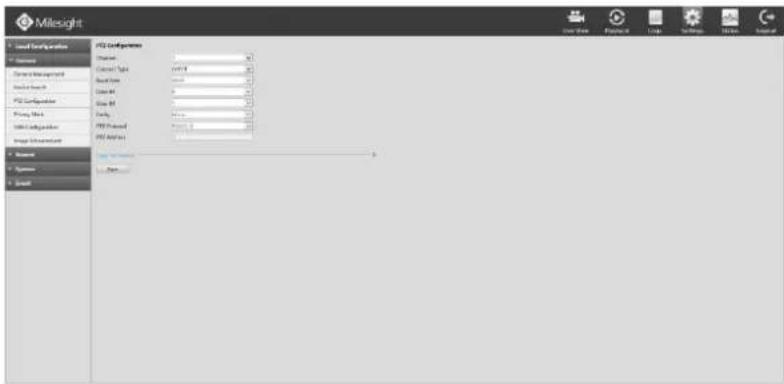
text_image
Milesight Load Configuration System System Management System Support PDS Configuration Working Work System Adjustment System Environment System System StartF-4.5.20
Note:
- The PTZ protocol and address of IP channel must be consistent with those of the PTZ decoder.
- Settings for a PTZ camera must be configured before it can be used. Make sure that the PTZ and RS-485 of the NVR are connected properly.
4.5.2.4 Privacy Mask
Milesight NVR support privacy mask. It is used to cover some privacy area which is not proper to appear on monitor.
You can add a privacy mask by following steps:
Step1. Click Settings→ Camera → Privacy Mask.
Step2. Select a channel, then select [enable].
Step3. To set a Privacy Mask, you can set values or draw a cover area on objects in the view.
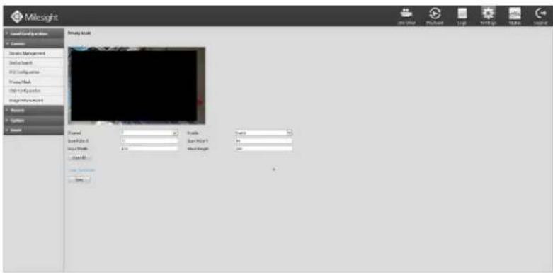
text_image
Milesight Local Configuration Customs Stream Management Device Stack View View Preview Book View View Options System System Summary World Formal Formal Formal Formal Formal Formal Formal Formal Formal Formal Formal Formal Formal Formal Formal Formal Formal Formal Formal Formal Formal Formal Formal Formal Formal Formal Formal Formal Formal Formal Formal Formal Formal FormalF-4.5.21
Step4. You can click [Copy] to copy the same configuration to other channels.
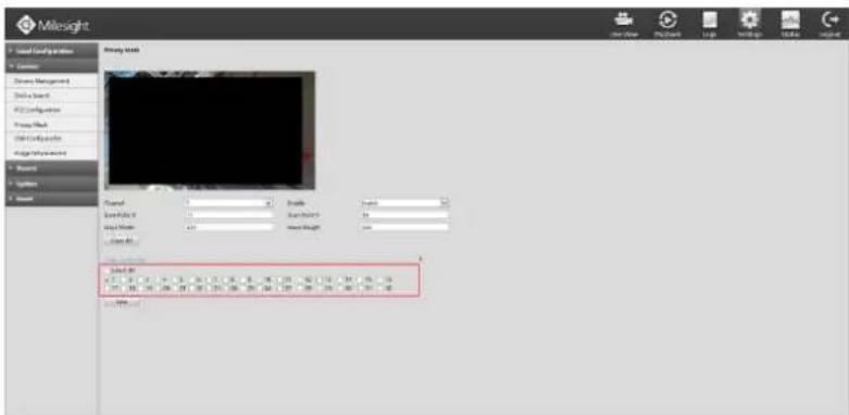
text_image
Milesight Local Configuration System Management Drive Search API Configuration Proxy Effect Drive Configuration Alpha/Alpha-Select System System Study Data Model 1 Scale: 0 Sample Size: 15 Sample Count: 49 Model 1 Scale: 0 Model 1 Scale: 0 Model 1 Scale: 0 Model 1 Scale: 0 Model 1 Scale: 0 Model 1 Scale: 0 Model 1 Scale: 0 Model 1 Scale: 0 Model 1 Scale: 0 Model 1 Scale: 0 Model 1 Scale: 0 Model 1 Scale: 0F-4.5.22
Step5. Select "Save" to save the settings.
Note:
[Start Point X] and [Start Point Y] determine the point where the area starts, [Mask Width] and [Mask Height] determine the size of the area.
4.5.2.5 OSD Configuration
You can set OSD (On Screen Display) on NVR, and the OSD will be synchronized to Camera. Click Settings → Camera → OSD Configuration.
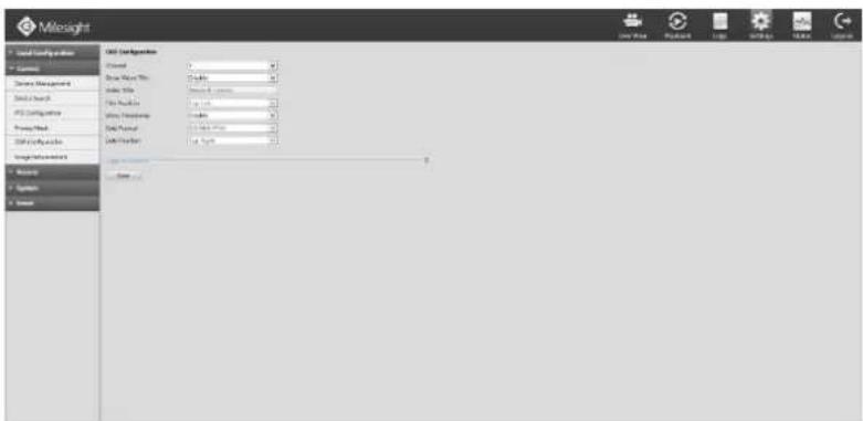
text_image
Mileight Local Security Information Current Show Date Time: 10 minutes Index Title: 100% or more File Address: 100% or more View Coordinate: 0.0000 Date Format: 0.0000 or more Date Provider: 0.0000 or more Source: System Source Mileight Configuration Data Date 12/12/2017F-4.5.23
Select channel and finish the info and save.
[Video Title]: Set the video title for the channel;
[Title Position]: Set the position for the video title: Top-Left or Top-Right;
[Date Position]: Set the position for the date: Top-Left, Top-Right, Bottom-Left or Bottom-Right;
[Date Format]: Set format for date: YYYY-MM-DD, MM/DD/YY or DD/MM/YYYY.
4.5.2.6 Image Enhancement
You can set Image Enhancement on NVR, and the configuration will be synchronized to Camera. Step1. Click Settings → Camera → Image Enhancement.
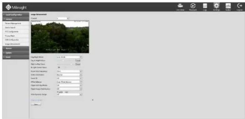
text_image
Milesight Local Currency Analysis Current Resource Management Distal Search AVD Configuration View Search USB Configuration Image Environment Shower Options Shower Image Environment Project Field Source: Project: 100% Field Source: View Light Color Value: View Light Color Value: View Light Frequency: View Light Duration: View Light Color Value: View Light Color Value: View Light Duration: View Light Color Value: View Light Duration: View Light Color Value: View Light Duration: View Light Duration: View Light Duration: View Light Duration: View Light Duration: View Light Duration: View Light Duration: View Light Duration: View Light Duration: View Light Duration: View Light Duration: View Light Duration: View Light Duration: View Light Duration: View Light Duration: View Light Duration: View Light Duration: View Light Duration: View Light Duration: View Light Duration: View Light Duration: View Light Duration: View Light Duration: View Light Duration: View Light Duration: View Light Period View Light Period View Light Period View Light Period View Light Period View Light Period View Light Period View Light Period View Light Period View Light Period View Light Period View Light Period View Light Period View Light Period View Light Period View Light Period View Light Period View Light Period View Light Period View Light Period View Light Period View Light Period View Light Period View Light Period View Light Period View Light PeriodF-4.5.24
Step2. Select channel by clicking the channel number on the right-top, the selected channel will change into gray and the channel number will change into yellow;
Step3. Set the configuration;
[Day/Night Mode]: Set the Day/Night mode for the channel;
[Day to Night Value]: Set the Minimum illumination intensity to trigger Night Mode;
[Night to Day Value]: Set the Maximum illumination intensity to trigger Day Mode;
[IR Light Sensor Value]: Shows the current value of IR light sensor;
[WDR/HLC]: Click to configure Wide Dynamic Range or High Light Control;
[Power Line Frequency]: 50Hz and 60Hz are available;
[Video Orientation]: Set the image rotation;
[Smart IR]: Set the Smart IR on and off;
[White Balance]: Choose a white balance mode for the channel;
[Digital Anti-fog Mode]: Set the Anti-fog function on and off;
[Digital Image Stabilisation]: Set the Image Stabilisation on and off.
4.5.3 Record
Preparation for Configuration
Step1. Ensure your NVR has installed and initialized the HDD.
Click Settings→ System → Disk Management
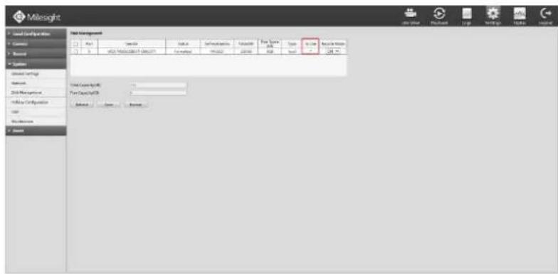
text_image
Milesight Local Configurations Current Report System Global Settings Network 3D Management Web by Configuration User Web Resources Data Management Data Settings Parameters File Name Type Access Form Name Total Capacity (MB) Total Capacity (MB) Address View BrowseF-4.5.25
Step2. Ensure that the HDD has sufficient storage space.
Click Settings → System → Disk Management. Select [Recycle Mode] to "ON" in the case of insufficient capacity of HDD.
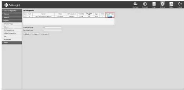
text_image
Milesight File Management File Name: 100 File Description: File Type: Normal File Region: Normal File Type: Normal File Region: Normal File Type: Normal File Region: Normal File Type: Normal File Region: Normal File Type: Normal File Region: Normal File Type: Normal File Region: Normal File Type: Normal File Region: Normal File Type: Normal File Region: Normal File Type: Normal File Region: Normal File Type: Normal File Region: Normal File Type: Normal File Region: NormalF-4.5.26
4.5.3.1 Record Mode
Step1. Click Settings → Record → Record Mode.
There are three record modes: No Recording/Always Record/Record by Schedule. You can select the desired one for every channel.
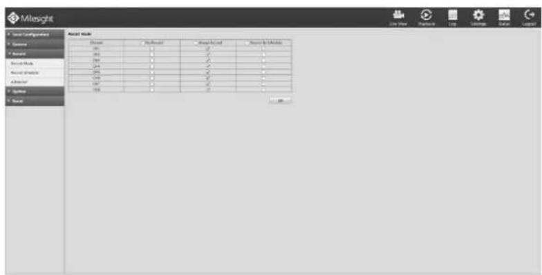
text_image
Milesight Model Name Name: Model 1 Model 2 Model 3 Model 4 Model 5 Model 6 Model 7 Model 8 Model 9 Model 10 Model 11 Model 12 Model 13 Model 14 Model 15 Model 16 Model 17 Model 18 Model 19 Model 20 Model 21 Model 22 Model 23 Model 24 Model 25 Model 26 Model 27 Model 28 Model 29 Model 30 Model 31 Model 32 Model 33 Model 34 Model 35 Model 36 Model 37 Model 38 Model 39 Model 40 Model 41 Model 42 Model 43 Model 44 Model 45 Model 46 Model 47 Model 48 Model 49 Model 50 Model 51 Model 52 Model 53 Model 54 Model 55 Model 56 Model 57 Model 58 Model 59 Model 60 Model 61 Model 62 Model 63 Model 64 Model 65 Model 66 Model 67 Model 68 Model 69 Model 70 Model 71 Model 72 Model 73 Model 74 Model 75 Model 76 Model 77 Model 78 Model 79 Model 80 Model 81 Model 82 Model 83 Model 84 Model 85 Model 86 Model 87 Model 88 Model 89 Model 90 Model 91 Model 92 Model 93 Model 94 Model 95 Model 96 Model 97 Model 98 Model 99 SystemF-4.5.27
[No Record]: NVR will not record;
[Always Record]: NVR will always record the chosen channel;
[Record By Schedule]: NVR will record by schedule, details will be shown in 4.5.3.2;
Step2. Click [OK] to save the configuration.
4.5.3.2 Record Schedule
Note:
The days are divided as
Holiday/Sunday/Monday/Tuesday/Wednesday/Thursday/Friday/Saturday. The schedule of Holiday is superior to other days. To set the holiday information, go to Chapter 4.5.4.4
Method1. General Setting
Step1. Click Record Settings → Record Schedule.
Step2. Select the desired channel (e.g. Channel 1).
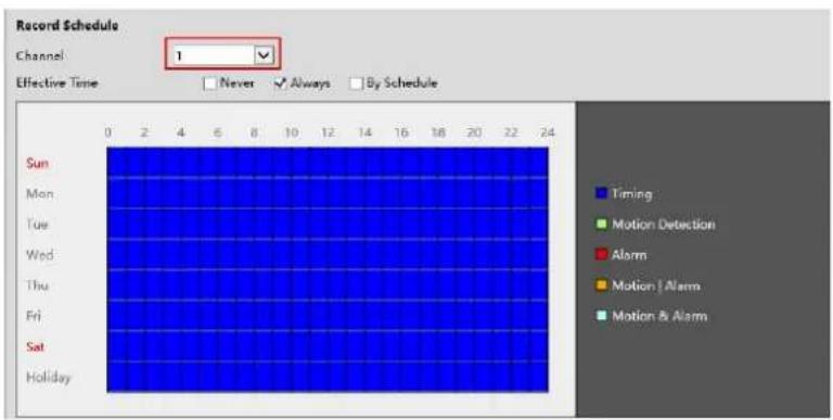
text_image
Record Schedule Channel 1 Effective Time Never Always By Schedule Sun Mon Tue Wed Thu Fri Sat Holiday Timing Motion Detection Alarm Motion | Alarm Motion & AlarmF-4.5.28
Step3. Set record schedule.
Never, Always and By Schedule are available for time setting. If you choose By Schedule, select a
day from the drop-down list of [Day], click to set a period, up to 12 periods can be set. (e.g.01:00 to 05:00 for none recording; 06:00 to 18:00 for timing recording; 19:00 to 21:00 for Motion recording; 22:00 to 24:00 for Alarm recording)
| Sun | Mon | Tue | Wed | Thu | Fri | Sat | Holiday |
| Period | Start Time | End Time | Record Type | ||||
| 1 | 00:00 | 24:00 | Timing | ||||
| 2 | 00:00 | 00:00 | Timing | ||||
| 3 | 00:00 | 00:00 | Timing | ||||
| 4 | 00:00 | 00:00 | Timing | ||||
| 5 | 00:00 | 00:00 | Timing | ||||
| 6 | 00:00 | 00:00 | Timing | ||||
| 7 | 00:00 | 00:00 | Timing | ||||
| 8 | 00:00 | 00:00 | Timing | ||||
| 9 | 00:00 | 00:00 | Timing | ||||
| 10 | 00:00 | 00:00 | Timing | ||||
| 11 | 00:00 | 00:00 | Timing | ||||
| 12 | 00:00 | 00:00 | Timing | ||||
| Select All | |||||||
| Sun Mon Tue Wed Thu Fri Sat Holiday Copy to Week | |||||||
| Sun Mon Tue Wed Thu Fri Sat Holiday | |||||||
| Period Start Time End Time Record Type Record Type | |||||||
| 1 00:00 24:00 Timing Motion Detection Alarm Motion | Alarm Motion & Alarm Timing | |||||||
| 4 00:00 00:00 Timing | |||||||
| 5 00:00 Motion & Alarm Timing | |||||||
| 6 00:00 00:00 Timing | |||||||
| 7 00:00 00:00 Timing | |||||||
| 8 00:00 00:00 Timing | |||||||
| 9 00:00 00:00 Timing | |||||||
| 10 00:00 00:00 Timing | |||||||
| 11 00:00 00:00 Timing | |||||||
| 12 00:00 00:00 Timing | |||||||
| □ Select All Copy to Week □ Sun Mon Tue Wed Thu Fri Sat Holiday □ | |||||||
F-4.5.29
F-4.5.30
Click and check to copy to other channels.
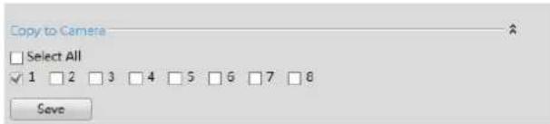
text_image
Copy to Camera □ Select All ✓ 1 □ 2 □ 3 □ 4 □ 5 □ 6 □ 7 □ 8 Save4.5.3.3 Advanced
Make advanced configuration for selected channels. Click and check to copy configurations to other channels.

text_image
Mitsight Local Configuration Customs Hardware Record Mode Record Symbol Information Systems System Background Name File Record Session Time Post Record Session Time Static Record Record Mode Type Data Type Background NameF-4.5.31
[Channel]: Select the channel which will be set.
[Pre Record]: Enable/Disable pre record before the event is triggered
[Duration Time]: Event post-record duration time
[Post Record]: Enable/Disable post record after the event is over
[Duration Time]: Event post-record duration time
[Audio Record]: Select to record audio or not
[Record Stream Type]: Select Main stream or sub stream for record
Lastly, you can choose the copy button to copy the settings of record to other channels.
[Due Time]: Set the due time of recording files.
4.5.4 System
4.5.4.1 General Settings
Click Settings → System → General Settings
To setup the general parameters of NVR, including modify the host name, device ID, select resolution, and set system time manually, etc.
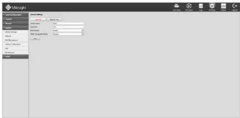
text_image
Milesight General Settings Location Data & Data Location name: mcp Network ID: 21 System path: 0.0000 FIMI Compaitive Data: 0.0000 Network Data Management Utility Configuration User Maintenance SourceF-4.5.32
4.5.4.2 Network Settings
4.5.4.2.1 Basic Configuration
Click Settings→System→Network, select "Basic" page
Basic configuration includes working mode, IP address, subnet mask, gateway, MTU, DNS server, etc.
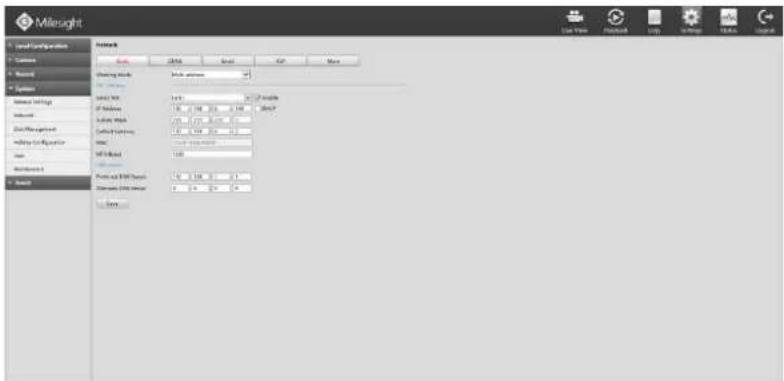
text_image
Milesight Local Configuration Camera Network Systems Network Linkage Network Data Management Webing Linkage User Networks Network Network Linkages Network Linkages Network Linkages Network Linkages Network Linkages Network Linkages Network Linkages Network Linkages Network Linkages Network Linkages Network Linkages Network Linkages Network Linkages Network Linkages Network Linkages Network Linkages Network Linkages Network Linkages Network Linkages Network Linkages Network Linkages Network Linkages Network Linkages Network Linkages Network Linkages Network Linkage Network Linkage Network Linkage Network Linkage Network Linkage Network Linkage Network Linkage Network Linkage Network Linkage Network Linkage Network Linkage Network Linkage Network Linkage Network Linkage Network Linkage Network Linkage Network Linkage Network Linkage Network Linkage Network Linkage Network Linkage Network Linkage Network Linkage Network Linkage Network Linkage Network LinkAge Network LinkAge Network LinkAge Network LinkAge Network LinkAge Network LinkAge Network LinkAge Network LinkAge Network LinkAge Network LinkAge Network LinkAge Network LinkAge Network LinkAge Network LinkAge Network LinkAge Network LinkAge Network LinkAge Network LinkAge Network LinkAge Network LinkAge Network LinkAge Network LinkAge Network LinkAge Network LinkAge Network LinkAge Network LinkAge Network LinkAge Network LinkAge Network LinkAge Network LinkAge Network LinkAge Network LinkAge Network LinkAge Network LinkAge Network LinkAge Network LinkAge Network LinkAge Network LinkAge Network LinkAge Network LinkAge Network LinkAge Network LinkAge Network LinkAge Network LinkAge Network LinkAgeF-4.5.33
Note:
- Check the DHCP check-box when there is a DHCP server running in the networks.
- The valid range of MTU is 500\~9676.
- Do not input an IP address conflict with another device.
4.5.4.2.2 PPPoE
Click Settings → System → Network. Select "PPPoE" page
Check the PPPoE check-box to enable the feature, and then input user name, password and confirm password for PPPoE access.
text_image
Milesight User Configuration Database Browse Systems Organic Storage System Storage Data Centers Holding Configuration Show Show Preferences Network Address Name: Address Name: Phone: Phone Address: ShareF-4.5.34
Note:
- User name and password of PPPoE can be obtained from your service provider. Once the setup is completed, a connected status will be shown.
- PPPoE function is not available for 4K/H.265 series NVR.
4.5.4.2.3 DDNS
Click Settings→System→Network, Select "DDNS"
If your NVR connected to network through PPPoE, you may need DDNS to solve the dynamic IP address problem. You need to check DDNS check-box to enable it, then select a DDNS Server, input the user name, password and host name. Do not forget to save the configuration.
Note:
"Host Name" must begin with letters, and it can only contain number, letters, and hyphen.
text_image
Milesight Source: Coding session Content Record Operator Current Settings Network 24. Management Webing Configuration Name Parameters Network Data (01) Data (02) Data (03) Data (04) Data (05) Data (06) Data (07) Data (08) Data (09) Data (10) Data (11) Data (12) Data (13) Data (14) Data (15) Data (16) Data (17) Data (18) Data (19) Data (20) Data (21) Data (22) Data (23) Data (24) Data (25) Data (26) Data (27) Data (28) Data (29) Data (30) Data (31) Data (32) Data (33) Data (34) Data (35) Data (36) Data (37) Data (38) Data (39) Data (40) Data (41) Data (42) Data (43) Data (44) Data (45) Data (46) Data (47) Data (48) Data (49) Data (50) Data (51) Data (52) Data (53) Data (54) Data (55) Data (56) Data (57) Data (58) Data (59) Data (60) Data (61) Data (62) Data (63) Data (64) Data (65) Data (66) Data (67) Data (68) Data (69) Data (70) Data (71) Data (72) Data (73) Data (74) Data (75) Data (76) Data (77) Data (78) Data (79) Data (80) Data (81) Data (82) Data (83) Data (84) Data (85) Data (86) Data (87) Data (88) Data (89) Data (90) Data (91) Data (92) Data (93) Data (94) Data (95) Data (96) Data (97) Data (98) Data (99) Data (100)F-4.5.35
4.5.4.2.4 Email
Click Settings → System → Network → Email
Set the Sender E-mail Address, User Name, Password, and SMTP Server:
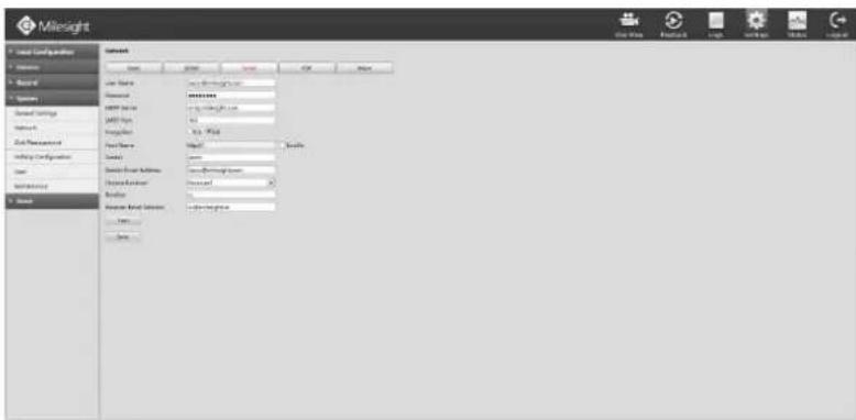
text_image
Milesight Local Configuration Description Balance System Standard Settings Network Data Parameters Web Configuration User Web System Name Description Description Description Description Description Description Description Description Description Description Description Description Description Description Description Description Description Description Description Description Description Description Description Description Description Description Description Description Description Description Description Description Description Description Description Description Description Description Description Description Description Description Description Description Description Description Description Description Description Description Explanation Description Description Description Description Description Description Description Description Description Description Description Description Description Description Description Description Description Description Description Description Description Description Description Description Description Description Description Description Description Description Description Description Description Description Description Description Description Description Description Description Description ExplanationF-4.5.36
[User name]: The E-mail address you choose to send emails.
[Password]: The password of the E-mail.
[SMTP Server]: The SMTP Server of your E-mail.
[SMTP Port]: The port of SMTP Server, it's usually 25.
[Encryption]: Security Protocol of email sending, includes TLS and SSL.
[Host Name]: For attaching URL when sending emails.
[Sender]: Named by yourself for the Sender E-mail.
[Sender Email Address]: It must be same with [User name].
[Choose Receiver]: You can have 3 receivers once.
[Receiver]: Named by yourself for the Receiver E-mail.
[Receiver Email Address]: E-mail Address for the receivers.
Select [Test] to check if the Mail function is workable
text_image
Message from webpage Sending Email Successfully. OKNote:
- Email will send you a screenshot when motion detection is triggered.
- If your NVR has a port forwarding IP for Host Name, please input the complete address that contains the port.
4.5.4.2.5 P2P
You can watch remote NVR live view in WAN by P2P on M-Sight Pro or M-VMS and there is no necessary to port forwarding any router.
Step1. Click Settings → System → Network → P2P.
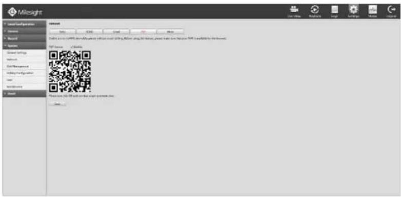
text_image
Milesight Local Configurations Services Business Services General Settings Networks Data Management Webging Configuration User System Services Download Settings Settings Settings Settings Settings Settings Settings Settings Settings Settings Settings Settings Settings Settings Settings Settings Settings Settings Settings Settings Settings Settings Settings Settings Settings Settings Settings Settings Settings Settings Settings Settings Settings Settings Settings Settings Settings Settings Settings Settings Settings Settings Settings Settings Settings Settings Settings Settings Settings Settings Instructions Instructions Instructions Instructions Instructions Instructions Instructions Instructions Instructions Instructions Instructions Instructions Instructions Instructions Instructions Instructions Instructions Instructions Instructions Instructions Instructions Instructions Instructions Instructions Instructions Instructions Instructions Instructions Instructions Instructions Instructions Instructions Instructions Instructions Instructions Instructions Instructions Instructions Instructions Instructions Instructions Instructions Instructions Instructions Instructions Instructions Instructions Instructions Instructions Instructions Requests: 10.0000000000000000000000000000000000000000000000000000000000000000000000000000000000000000000000000000F-4.5.37
Step2. Click "Enable" to enable the function ;
Step3. Click "Save" to save the configuration.
Note: For security reasons, P2P function need to be registered before being used if your NVR is:
①MS-Nxxxx-UH/UPH and the firmware version is 71.7.0.5-r13 or above;
②MS-Nxxxx-UT/UPT and the firmware version is 72.7.0.5-r13 or above.
You can contact your reseller for help.
If NVR failed to save configuration, check these possibilities:
| Marked Words | Description |
| Network Error. | Check the network condition. |
| Register failed. | MAC address doesn’t register the P2P. |
| Unknown Error. | Need to contact with Milesight Support. |
After enabling, you can add the NVR on the APP M-Sight Pro or M-VMS for live view via scanning the QR code on the "P2P" page directly, or inputting the MAC address manually.
4.5.4.2.6 More
Click Settings → System → Network → More
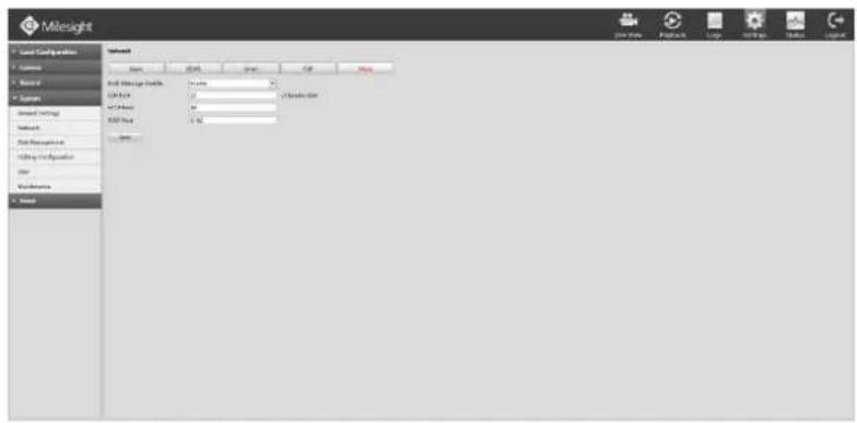
text_image
Milesight Local Configuration System Speed 2000 Speed GIF Speed Total Wireless Modles: 1.000 1/240000000 367.5GHz 2.000 1/240000000 Total Network Network Data Management Data Misinformation User Webmaster SystemF-4.5.38
Push Message Enable
With this option enabled, you can receive the alarm message on the mobile application(M-Sight Pro or M-VMS).
SSH Port Setting
Secure Shell (SSH) has many functions; it can replace Telnet, and also provides a secure channel for FTP, POP, even for PPP.
Note:
The default SSH port is 22.
HTTP Port Setting
The default HTTP port is 80. Please modify HTTP ports according to actual application.
Note:
-
The default HTTP port for IE browser is 80.
-
HTTP port is used for remote network access.
RTSP Port Setting
Real Time Streaming Protocol (RTSP) is an application layer protocol in TCP/IP protocol system.
The default RTSP port is 554. Please modify RTSP port according to actual application.
Note:
-
RTSP port is used for remote network live view.
-
RTSP port valid range is 554 or 1024\~65535.
Service Port Setting
Service Port is used to get remote access when you add NVR by mobile devices.
The default Service port is 1100. Please modify Service port according to actual application.
Note:
-
This option is not available for 4K/H.265 series NVR.
-
You can add this port when using P2P/port mapping/LAN IP to add NVR, but you need to
use port 80 to add 4K/H.265 series NVR.
- For port mapping, you still need map 554 to 554. Only then. Only then you can use 1100 to watch the live view by remote WAN.
4.5.4.3 Disk Management
Click Settings → System → Disk Management
Configuration page contains the basic information of the disk, see F-4.5.40. Select a disk and click [Format] to format the disk.
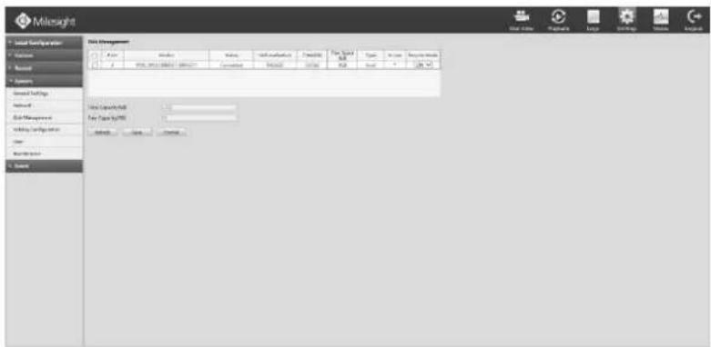
text_image
Milesight Local Configulator Variables Report Systems General Settings Network Data Management Utility Settings Other System Data Management File Path: 100% Type: Normal Status: Normal Access: Normal Control:F-4.5.39
[RAID Mode]: Enable/Disable to open/close RAID function.
[HDD Type]: Show RAID* means RAID, show LOCAL means normal disk mode.
Note:
RAID* stands for 0/1/5/10
4.5.4.4 Holiday Configuration
It can configure the record or image capture schedule for holidays of the current year.
Step1. Click Setting→System→Holiday Configuration.
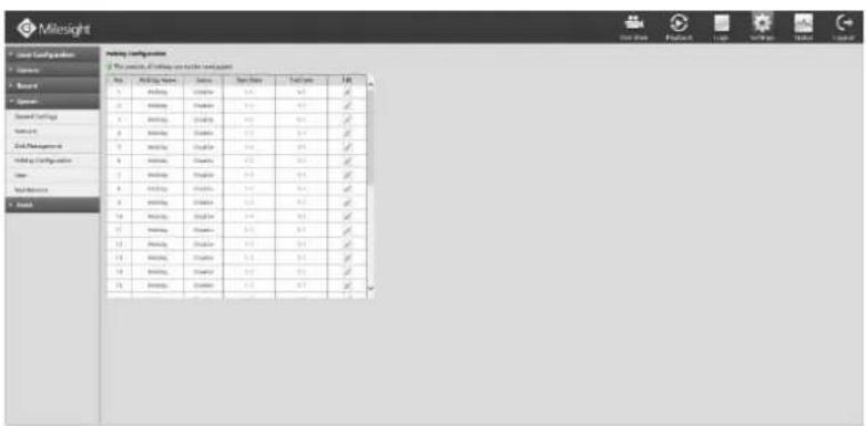
text_image
Milesight Local Configuration Parameters Report Operator Speed Settings Networks 2nd Management Holding Configuration Name Model Model Name Date Time Date Start Date End Date File Path File Path File Path File Path File Path File Path File Path File Path File Path File Path File Path File Path File Path File Path File Path File Path File Path File Path File Path File Path File Path File Path File Path File Path File Path File Path File Path File Path File Path File Path File Path File Path File Path File PathF-4.5.40
Step2. Edit the holiday schedule.
Click to open holiday configuration page to modify holiday name, check the 'Holiday Enable'
check-box, and then select [Type] to setup Start/End date. There are Month, Week, and Date in [Type] mode. Then click [OK] to save the configuration and return to holiday configuration page.
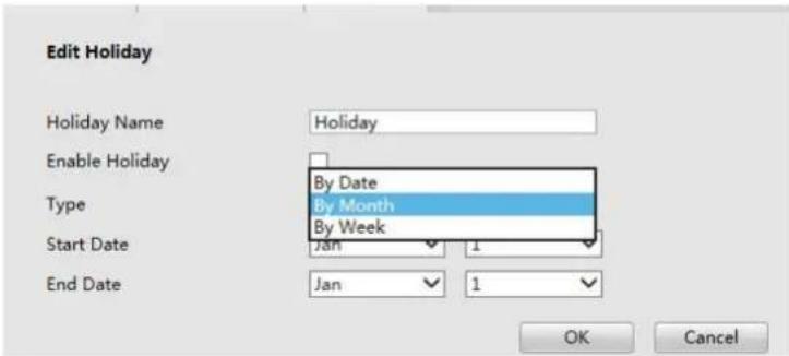
text_image
Edit Holiday Holiday Name Holiday Enable Holiday Type By Date By Month By Week Start Date Jan 1 End Date Jan 1 OK CancelF-4.5.41
4.5.4.5 User
Step1. Click Settings → System → User.
Note:
- If the NVR firmware version out of the factory is xx.7.0.6 or above, the default user name is "admin" and the default password is "ms1234";
- If the NVR firmware is upgraded to xx.7.0.6 or above from a lower version, the default password will turn to "ms1234" after a reset, or it will keep the old default password "123456";
- If the NVR firmware version is below xx.7.0.6, the default user name is "admin" and the default password is "123456".
Step2. Add a new user.
Click [Add] to enter the user add menu, input information for the new user, select user level and set user privileges, then click [OK] to save settings.
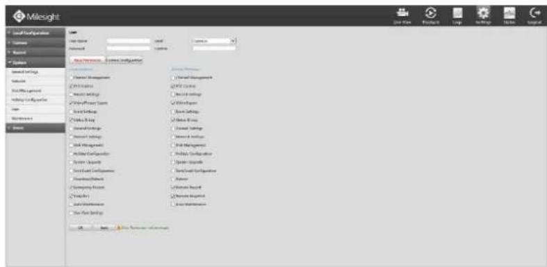
text_image
Milesight Local Configuration System Material Options Model Settings Solution Data Management Model Configuration User Parameters System Local Settings Local Settings Local Settings Local Settings Local Settings Local Settings Local Settings Local Settings Local Settings Local Settings Local Settings Local Settings Local Settings Local Settings Local Settings Local Settings Local Settings Local Settings Local Settings Local Settings Local Settings Local Settings Local Settings Local Settings Local Settings Local Settings Local Settings Local Settings Local Settings Local Settings Local Settings Local Settings Local Settings Local SettingsF-4.5.42
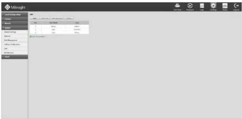
text_image
Milesight Local Configuration Current Maximum Custom Standard Settings Network Total Management Link Configuration User Performance Select File Path Name Address Access File Path Status: Normal 1 2 3 4 5 6 7 8 9 10 11 12 13 14 15 16 17 18 19 20 21 22 23 24 25 26 27 28 29 30 31 32 33 34 35 36 37 38 39 40 41 42 43 44 45 46 47 48 49 50 51 52 53 54 55 56 57 58 59 60 61 62 63 64 65 66 67 68 69 70 71 72 73 74 75 76 77 78 79 80 81 82 83 84 85 86 87 88 89 90 91 92 93 94 95 96 97 98 99 100F-4.5.43
Step3. Edit user.
Select a desired user and click, when the color below changes into blue, click [Edit Limit] to edit user privileges, click [Edit Password] to change password.
Note:
- User name can only contain letters and number. There are two user levels with different authority: Operator and Viewer;
- [Local Privilege] means the privilege to the monitor connected with NVR, while the [Remote Privilege] means the privilege to web settings.
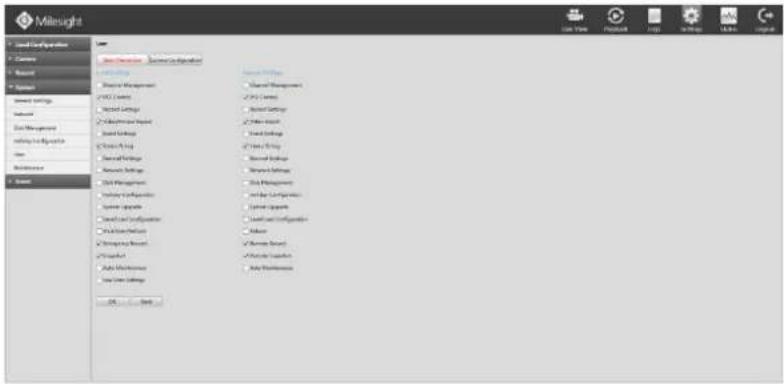
text_image
Milneught System Configuration Camera Network Parameters System Settings Network Data Management rating to Resources View Maintenance System System Settings System Settings System Settings System Settings System Settings System Settings System Settings System Settings System Settings System Settings System Settings System Settings System Settings System Settings System Settings System Settings System Settings System Settings System Settings System Settings System Settings System Settings System Settings System Settings System Settings System Settings System Settings System Settings System Settings System Settings System Settings System Settings System Settings System SettingsF-4.5.44
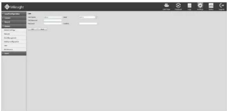
text_image
Milesight Local Configuration Name Password Accession Email Email Name: Password: Connection: OK NextF-4.5.45
Step4. Click to delete a user.
4.5.4.6 Maintenance
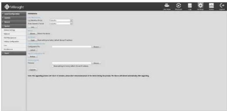
text_image
Milesight Local Configuration Content Network System External Settings Networks Total Management Utility Configuration Name Description Target Parameters Local Configuration To: Contact Address Address to: https://www.milesight.com/ Address Address to: https://www.milesight.com/ Address Source: The applicable version of the Milesight system, please check the following power of the device during the process. The device will switch automatically after ordering.F-4.5.46
4.5.4.6.1 Auto Maintenance
You can set the Log and Photo Retention Period (from 1 to 12 months or permanently) in the Auto Maintenance interface. According to your configuration, the NVR will automatically delete your logs and photos after the retention period or permanently keep the Log and Photo.
4.5.4.6.2 Reboot
Click to reboot the NVR.
4.5.4.6.3 Reset
Click to reset the NVR to factory defaults.
4.5.4.6.4 Import Configuration File
Click to select one desired file and click to restore the NVR configuration.
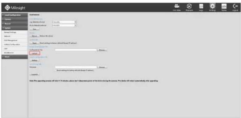
text_image
Milesight Local Configuration Access Show System Show Settings Network Add Management Add Security OK Outperform Help Settings Key Key Settings Key Settings Key Settings Key Settings Key Settings Key Settings Key Settings Key Settings Key Settings Key Settings Key Settings Key Settings Key Settings Key Settings Key Settings Key Settings Key Settings Key Settings Key Settings Key Settings Key Settings Key Settings Key Settings Key Settings Key Settings Key Settings Key Settings Key Settings Key Settings Key Settings Key Settings Key Settings Key Settings Key SettingsF-4.5.47
4.5.4.6.5 Export Configuration File
Click to backup present settings.
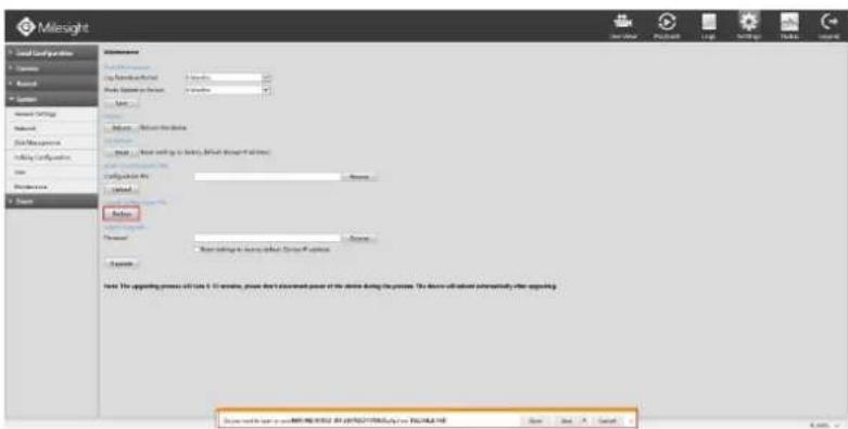
text_image
Milesight Local Configuration Comms Rustal System System Settings Network Data Management Webing Configuration Name Description Balance Settings Form 1 Form 2 Form 3 Form 4 Form 5 Form 6 Form 7 Form 8 Form 9 Form 10 Form 11 Form 12 Form 13 Form 14 Form 15 Form 16 Form 17 Form 18 Form 19 Form 20 Form 21 Form 22 Form 23 Form 24 Form 25 Form 26 Form 27 Form 28 Form 29 Form 30 Form 31 Form 32 Form 33 Form 34 Form 35 Form 36 Form 37 Form 38 Form 39 Form 40 Form 41 Form 42 Form 43 Form 44 Form 45 Form 46 Form 47 Form 48 Form 49 Form 50 Form 51 Form 52 Form 53 Form 54 Form 55 Form 56 Form 57 Form 58 Form 59 Form 60 Form 61 Form 62 Form 63 Form 64 Form 65 Form 66 Form 67 Form 68 Form 69 Form 70 Form 71 Form 72 Form 73 Form 74 Form 75 Form 76 Form 77 Form 78 Form 79 Form 80 Form 81 Form 82 Form 83 Form 84 Form 85 Form 86 Form 87 Form 88 Form 89 Form 90 Form 91 Form 92 Form 93 Form 94 Form 95 Form 96 Form 97 Form 98 Form 99 Form 100F-4.5.48
4.5.4.6.6 System Upgrade
Click to select the firmware file, and you can check to reset configuration to factory defaults.
Click to upgrade.
Note:
It will take 5 to 10 minutes to upgrade, please do not cut off the device power during the upgrade. After upgrading, the device will reboot automatically.
4.5.5 Event
4.5.5.1 Motion Detection
Step 1. Click Settings → Event → Motion Detection.
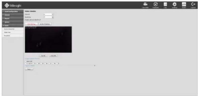
text_image
Milesight File Edit View Help Tools Help Tools Help Tools Help Tools Help Tools Help Tools Help Tools Help Tools Help Tools Help Tools Help Tools Help Tools Help Tools Help Tools Help Tools Help Tools Help Tools Help Tools Help Tools Help Tools Help Tools Help Tools Help Tools Help Tools Help Tools Help Tools Help Tools Help Tools Help Tools Help Tools Help Tools Help Tools Help Tools Help Tools Help Tools Help Tools Help Tools Help Tools Help Tools Help Tools Help Tools Help Tools Help Tools Help Tools Help Tools Help Tools Help Tools Help Tools Help Tools Help Tools Help Tots Current Settings Balance Help Time Help Time Help Time Help Time Help Time Help Time Help Time Help Time Help Time Help Time Help Time Help Time Help Time Help Time Help Time Help Time Help Time Help Time Help Time Help Time Help Time Help Time Help Time Help Time Help Time Help Time Help Time Help Time Help Time Help Time Help Time Help Time Help Time Help TimeF-4.5.49
Step 2. Set the trigger area for motion detection.
You can select an area by dragging the mouse to set the trigger area, and this area will be synchronized to camera.
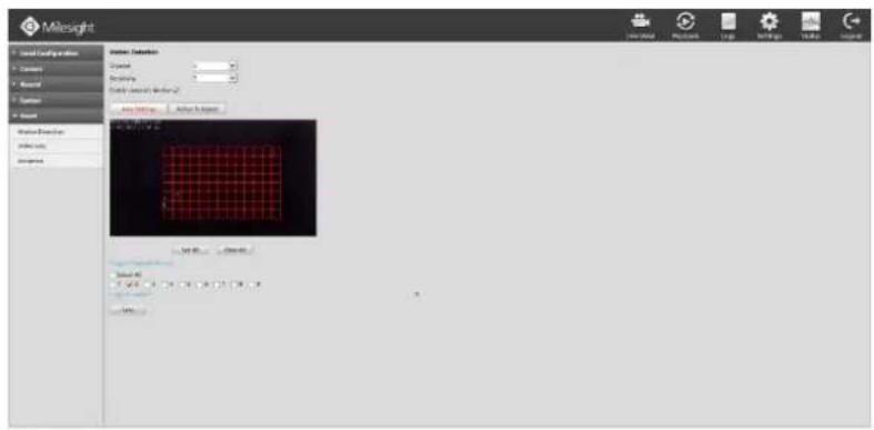
text_image
Milesight Material Configuration Constant Maximal Custom Order Material Description Index Line Description Index Line Description Index Line Description Index Line Description Index Line Description Index Line Description Index Line Description Index Line Description Index Line Description Index Line Description Index Line Description Index Line Description Index Line Description Index Line Description Index Line Description Index Line Description Index Line Description Index Line Description Index Line Description Index Line Description Index Line Descart 01 Descart 02 Descart 03 Descart 04 Descart 05 Descart 06 Descart 07 Descart 08 Descart 09 Descart 10F-4.5.50
Step 3. Select the schedule, sensitivity and trigger area for motion detection.
[Enable camera's Motion]: If it is enabled here, motion detect will take effect 7*24h; If it is not enabled, motion detect will take effect as the schedule which is set on the camera web.
[Set All]: Set all area as the trigger area;
[Clear All]: Clear all trigger area;
[Sensitivity]: Set sensitivity for motion detection, range from 1 to 10. It will synchronize to IPC if you set sensitivity here;
Step 4. Select the desired channel and check to configure motion detection action.
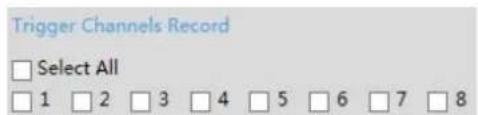
text_image
Trigger Channels Record □ Select All □ 1 □ 2 □ 3 □ 4 □ 5 □ 6 □ 7 □ 8Step 5. Click the [Action Schedule] to edit effective time and action once motion is detected. Edit the schedule and action.
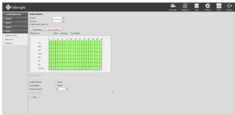
text_image
Milesight Local Configuration Customs New Style Global - 100% Options Options Options Material Options Material Type: Color: 50% Size: 250 px By: 100% Color: 50% Color: 25% Color: 10% Color: 5% Color: 2% Color: 1% Color: 5% Color: 2% Color: 1% Color: 5% Color: 2% Color: 1% Color: 5% Color: 2% Color: 1% Color: 5% Color: 2% Color: 1% Color: 5% Color: 2% Color: 1% Color: 5% Color: 2% Color: 1% Color: 5% Color: 3% Color: 1% Color: 5% Color: 2% Color: 1% Color: 5% Color: 3% Color: 1% Color: 5% Color: 2% Color: 1% Color: 5% Color: 3% Color: 1% Color: 5% Color: 2% Color: 1% Color: 5% Color: 3% Color: 1% Color: 4% Color: 2% Color: 1% Color: 4%F-4.5.51
[Audible Warning]: NVR will trigger an audible beep when motion is detected;
[Email Linkage]: NVR will send an email to the address set before;
[Triggered Interval]: Set the interval between two events.
Note:
Motion record schedule is different from the schedule of the [Audible] and [Email Linkage]. Enter the Record Schedule by clicking Settings→Record→Record Schedule. Confirm the time to enable Motion Record.
4.5.5.2 Video Loss
Step1. Click Settings→Event→Video Loss.
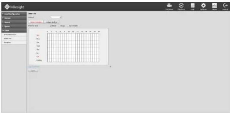
text_image
Milesight Local Configuration Commerce Business Organizers Search Home Search Video Tools Color Mode Movie Movie By Inside Color Color Color Color Color Color Color Color Color Color Color Color Color Color Color Color Color Color Color Color Color Color Color Color Color Color Color Color Color Color Color Color Color Color Color Color Color Color Color Color Color Color Color Color Color Color Color Color Color Color Price Price Price Price Price Price Price Price Price Price PriceF-4.5.52
Step2. Select a desired channel
Step3. Select effective time to setup when you want to trigger actions once video loss is
detected.
[Never]: Your NVR will not trigger any actions when [Never] button is checked. No matter the [Audible Warning] or [Email Linkage] check-boxes are checked or not.
[Always]: Your NVR will always trigger actions when [Always] button is checked. Please make sure [Audible Warning] or [Email Linkage] is checked.
[By Schedule]: Schedule can be set for all week or any day of the week with up to 12 time periods per day. Video loss actions take effect in the scheduled period only.
[Audible Warning]: NVR will trigger an audible beep when motion is detected.
[Email Linkage]: Send video loss note to specified email address when video loss is detected.(Please refer to 4.5.4.2.4 Email configuration for mail address setting)
[Trigger Interval]: Set the interval between two events.
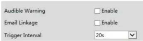
text_image
Audible Warning Enable Email Linkage Enable Trigger Interval 20s4.5.5.3 Exception
Step1. Click Settings → Event → Exception.
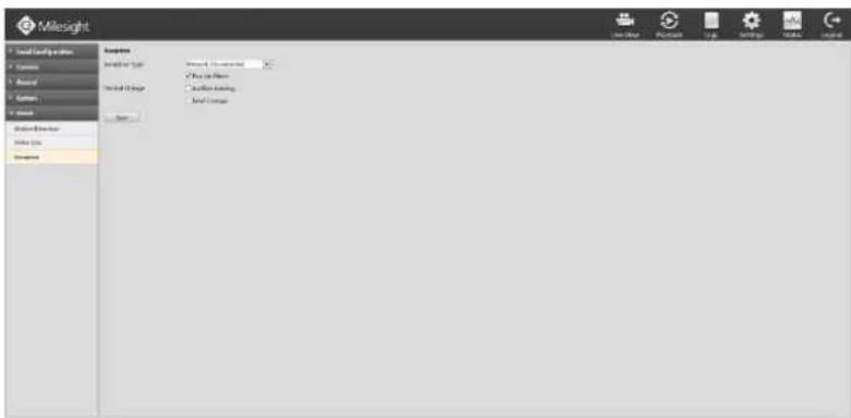
text_image
Milesight Local Security Options Customs Manual System System External Internal Security Internal Security External Security External Security External Security External Security External Security External Security External Security External Security External Security External Security External Security External Security External Security External Security External Security External Security External Security External Security External Security External Security External Security External Security External Security External Security External Security External Security External Security External Security External Security External Security External Security External Security External Security ExternalSecurityF-4.5.53
Step2. Select Exception Type. There are 4 kinds of alarm types.
[Network Disconnected]: Loss of network;
[HDD Full]: HDD full, it usually happens when Recycle Mode is OFF.
[Record Failed]: Recording fails, including HDD Failed, HDD Full and so on.
[HDD Failed]: Failed to recognize HDD.
[HDD Unformat]: HDD is unformat.
[No Disk]: There is no HDD.
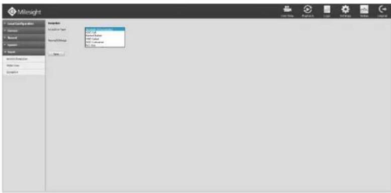
text_image
Milesight Local Security & Admin Parameters Report Parameters Search Security Function Model Tools Details Description: Add Data Remove Data Add Data Remove Data Add Data Remove Data Add Data Remove Data Add Data Remove Data Add Data Remove Data Add Data Remove Data Add Data Remove Data Add Data Remove Data Add Data Remove Data Add Data Remove Data Add Data Remove Data Add Data Remove Data Add Data Remove Data Add Data Remove Data Add Data Remove Data Add Data Remove Data Add Data Add Data Add Data Add Data Add Data Add Data Add Data Add Data Add Data Add Data Add Data Add Data Add Data Add Data Add Data Add Data Add Data Add Data Add Data Add Data Add Data Add Data Add Data Add Data Add Data Add Data Add Data Add Data Add Data Add Data Add Data Add Data Add Data Add TimeF-4.5.54
Step3. Select alarm type.
[Pop Up Alarm]: Will pop up a window if checked;
[Audible Warning]: NVR will trigger an audible beep when motion is detected;
[Email Linkage]: Email will be ready to sent if checked.
4.6 Status
You can have a quick view of the information of the device, network, camera, disk and event. This part is only for your rapid reference. If you want to make any configuration, please go to corresponding parts accordingly.
4.6.1 Device Information
Click Status→ Device Information
It will show you information in F-4.6.1, including: Device ID, Model, MAC Address, Hardware Version, Software Version and Uptime.
text_image
Milesight Category: Share Information Industrial Data Industrial Data Data Table Data Value Data Name Material Description Group Christopher File Path Date: 2015-04-28 Model: 10.0000000000000000000000000000000000000000000000000000000000000000000000000000000000000000000000 Model: 16.379999999999999999999999999999999999999999999999999999999999999999999999999999999999999999999999999999 Model: 16.379999999999999999999999999999999999999999999999999999999999999999 Model: 16.37888888888888888888888888888888888888888888888888888888888888888888888F-4.6.1
4.6.2 Network Status
Click Status→ Network Status
It will show you information in F-4.6.2, including: Free bandwidth, Used bandwidth, Connection, Mode, DHCP, MTU(B), IP Address, Net mask, Gateway, MAC, Preferred DNS Server, Alternate DNS Server, Receive Rate, and Send Rate.
text_image
Milesight User Name Information Material Name Current Value Local Data Current Value Current Value Current Value Current Value Current Value Current Value Current Value Current Value Current Value Current Value Current Value Current Value Current Value Current Value Current Value Current Value Current Value Current Value Current Value Current Value Current Value Current Value Current Value Current Value Current Value Current Value Current Value Current Value Current Value Current Value Current Value Current Value Current Value Current ValueF-4.6.2
4.6.3 Camera Status
Click Status→ Camera Status
It will show you information in F-4.6.3, including: Channel, Name, Status, IP Address, Record, Frame Rate, Bit rate and Resolution.
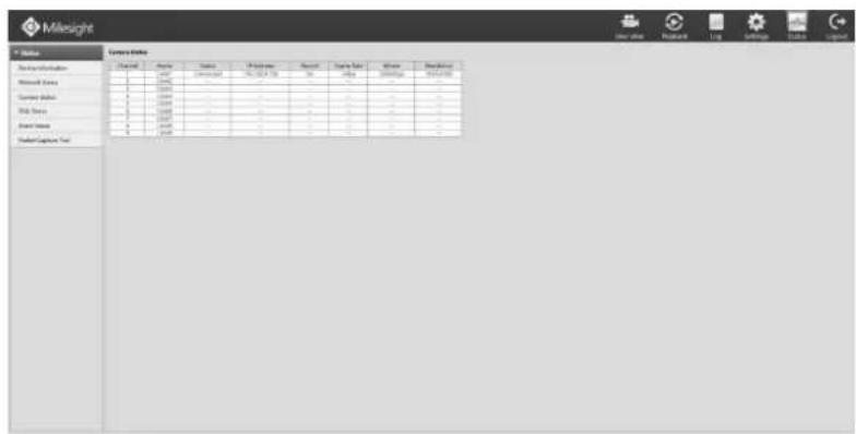
text_image
Milesight Center Data Design Name Parameter Parameters Parameters Data Name Parameter Parameters Parameters Data Name Parameter Parameters Parameters Data Name Parameter Parameters Parameters Data Name Parameter Parameters Parameters Data Name Parameter Parameters Parameters Data Name Parameter Parameters Parameters Data Name Parameter Parameters Parameters Data Name Parameter Parameters Parameters Data Name Parameter Parameters Parameters Data Name Parameter Parameters Parameters Datal Capture TestF-4.6.3
4.6.4 Disk Status
Click Status → Disk Status
It will show you information in F-4.6.4, including: Port, Vendor, status, Total(GB), Used(GB) Free
space(GB), HDD Type, In Use, and Recycle Mode. You can see the Total Capacity (GB) and Available Capacity (GB) as below:
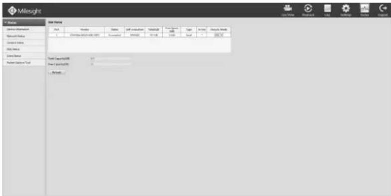
text_image
Milesight File Edit View Insert Tools Help Tools Help Tools Help Data History Product Category: 100 Data Category Value: 0 1. Bookets... Data Category: 100 Data Category Value: 0 Data Category Value: 0 Data Category Value: 0 Data Category Value: 0 Data Category Value: 0 Data Category Value: 0 Data Category Value: 0 Data Category Value: 0 Data Category Value: 0 Data Category Value: 0 Data Category Value: 0 Data Category Value: 0 Data Category Value: 0 Data Category Value: 0 Data Category Value: 0F-4.6.4
4.6.5 Event Status
Click Status → Event Status
It will show you information in F-4.6.5, including: Channel, Name, IP Address, Videoloss, Motion, I/O. Icon will light up as below:
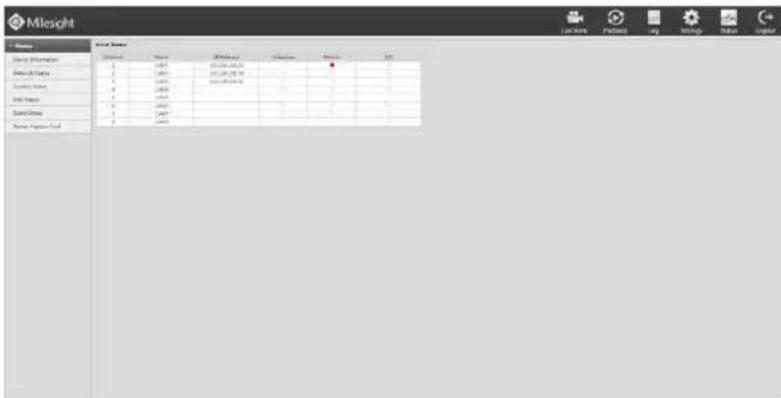
text_image
Milesight Current Value Current Value Current Value Current Value Current Value Current Value Current Value Current Value Current Value Current Value Current Value Current Value Current Value Current Value Current Value Current Value Current Value Current Value Current Value Current Value Current Value Current Value Current Value Current Value Current Value Current Value Current Value Current Value Current Value Current Value Current Value Current Value Current Value Current ValueF-4.6.5
4.6.6 Packet Capture Tool
Click Status→ Packet Capture Tool
Input IP and Port, then click [Start] to start capture and click [End] to stop. Click [Download] to backup the captured packet locally.
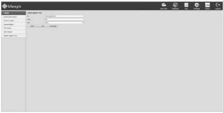
text_image
Mileight Name Source Information Source Index Current Date File Size Current Value Model Correct Tool Model Impact Tool 01.01.2019.01.01 04 05 06 07 08 09 10 11 12 13 14 15 16 17 18 19 20 21 22 23 24 25 26 27 28 29 30 31 32 33 34 35 36 37 38 39 40 41 42 43 44 45 46 47 48 49 50 51 52 53 54 55 56 57 58 59 60 61 62 63 64 65 66 67 68 69 70 71 72 73 74 75 76 77 78 79 80 81 82 83 84 85 86 87 88 89 90 91 92 93 94 95 96 97 98 99 100F-4.6.6
4.7 Logout
Click [Logout] to exit the current account.
text_image
Milenlight Model Selection Tool Name: milenlight Size: 100 mm Capacity: 5000 Control Status: 100% Model Name: milenlight Model Selection Tool Image Tools Help Image Tools Help Image Tools Help Image Tools Help Image Tools Help Image Tools Help Image Tools Help Image Tools Help Image Tools Help Image Tools Help Image Tools Help Image Tools Help Image Tools Help Image Tools Help Image Tools Help Image Tools Help Image Tools Help Image Tools Help Image Tools Help Image Tools Help Image Tools Help Image Tools Help Image Tools Help Image Tools Help Image Tools Help Image Tools help Image Tools help Image Tools help Image Tools help Image Tools help Image Tools help Image Tools help Image Tools help Image Tools help Image Tools help Image Tools help Image Tools help Image Tools help Image Tools help Image Tools help Image Tools help Image Tools help Image Tools help Image Tools help Image Tools help Image Tools help Image Tools help Image Tools help Image Tools help Image Tools help Image Tools Help Image Tools Help Image Tools Help Image Tools Help Image Tools Help Image Tools Help Image Tools Help Image Tools Help Image Tools Help Image Tools Help Image Tools Help Image Tools Help Image Tools Help Image Tools Help Image Tools HelpF-4.7.1
5. Services
Milesight Technology Co., Ltd provides customers with timely and comprehensive technical support services. End-users can contact your local dealer to obtain technical support. Distributors and resellers can contact directly with Milesight for technical support.
Technical Support Mailbox: support@milesight.com
Web: http://www.milesight.com
Online Problem Submission System: http://www.milesight.com/support/feedback.asp
Address: No.23 Wanghai Road, 2nd Software Park, Xiamen, China
Zip Code: 361006
TEL: +86-592-5922772
FAX: +86-592-5922775
Milesight
More in Sight