MS-N7032UH - Video recorder Milesight - Free user manual and instructions
Find the device manual for free MS-N7032UH Milesight in PDF.


User questions about MS-N7032UH Milesight
0 question about this device. Answer the ones you know or ask your own.
Ask a new question about this device
Download the instructions for your Video recorder in PDF format for free! Find your manual MS-N7032UH - Milesight and take your electronic device back in hand. On this page are published all the documents necessary for the use of your device. MS-N7032UH by Milesight.
USER MANUAL MS-N7032UH Milesight
These instructions are intended to ensure that user can use the product correctly to avoid danger or property loss. The precaution measures are divided into "Warnings" and "Cautions"
Warnings: Serious injury or death may be caused if any of these warnings is neglected.
Cautions: Injury or equipment damage may be caused if any of these cautions are neglected.
 |  |
| Warnings: Please follow these safeguards to prevent injury or death. | Cautions: Please follow these safeguards to prevent potential injury or material damage |

Warnings
This installation must be conducted by a qualified service person and should strictly comply with the electrical safety regulations of the local region
◆ To avoid risk of fire and electric shock, do keep the product away from rain and moisture
Do not touch components such as heat sinks, power regulators, and processors, which may be hot
◆ Source with DC 12V or PoE
◆ Please make sure the plug is firmly inserted into the power socket
When the product is installed on a wall or ceiling, the device should be firmly fixed
◆ If the product does not work properly, please contact your dealer. Never attempt to disassemble the camera by yourself

Cautions
◆ Make sure that the power supply voltage is correct before using the camera
Do not store or install the device in extremely hot or cold temperatures, dusty or damp locations, and do not expose it to high electromagnetic radiation
◆ Only use components and parts recommended by manufacturer
◆ Do not drop the camera or subject it to physical shock
◆ To prevent heat accumulation, do not block air circulation around the camera
◆ Laser beams may damage image sensors. The surface of image sensors
should not be exposed to where a laser beam equipment is used
◆ Use a blower to remove dust from the lens cover
◆ Use a soft, dry cloth to clean the surface of the camera. Stubborn stains can be removed using a soft cloth dampened with a small quantity of detergent solution, then wipe dry
Do not use volatile solvents such as alcohol, benzene or thinners as they may damage the surface finishes
◆ Save the package to ensure availability of shipping containers for future transportation
EU Conformity Statement

2012/19/EU (WEEE directive): Products marked with this symbol cannot be disposed of as unsorted municipal waste in the European Union. For proper recycling, return this product to your local supplier upon the purchase of equivalent new equipment, or dispose of it at designated collection points. For more information see: www.recyclethis.info.

2006/66/EC (battery directive): This product contains a battery that cannot be disposed of as unsorted municipal waste in the European Union. See the product documentation for specific battery information.
The battery is marked with this symbol, which may include lettering to indicate cadmium (Cd), lead (Pb), or mercury(Hg). For proper recycling, return the battery to your supplier or to a designated collection point. For more information see: www.recyclethis.info.
Content
- Product Introduction .... 1
1.1 Introduction....1
1.2 Product Key Functions....1
- Hardware 7
2.1 Panel Buttons and Lights Instructions....7
2.2 Using a USB Mouse....11
2.4 IR Remote Controller....12
2.5 Hard Disk Installation....14
2.5.1 MS-N7000 series Hard Disk Installation....14
2.5.2 MS-N8000 series Hard Disk Installation....17
- Local Operation 22
3.1 Wizard Setting....22
3.2 Playback....24
3.2.1 Video Playback....24
3.2.2 Video Files Backup....25
3.2.3 Picture Playback....27
3.2.4 Picture Files Backup....28
3.3 Camera Settings....29
3.3.1 Camera Management....29
3.3.2 Camera Search....34
3.3.3 PTZ Configuration....36
3.3.4 Privacy Mask 41
3.3.5 OSD configuration....42
3.4 Record Settings....43
3.4.1 Record Mode....44
3.4.2 Record Schedule Setting....44
3.4.3 Advanced settings....48
3.5 Event Settings....49
3.5.1 Video Loss....49
3.5.2 Motion Detection....52
3.5.3 Alarm Input....56
3.5.4 Alarm Output....58
3.5.5 Exception....59
3.6 Status....59
3.6.1 Device Information....60
3.6.2 Network Status....60
3.6.3 Camera Status....60
3.6.4 Disk Status....61
3.6.5 Event Status....61
3.7 Live View Settings....62
3.7.1 Live View....62
3.7.2 Layout Configuration....64
3.7.3 Live View Parameter....64
3.8 System Settings....65
3.8.1 General Setting....65
3.8.2 Network Settings....66
3.8.3 Disk Management....71
3.8.4 Holiday Configuration....72
3.8.5 User Account Settings....73
3.8.6 Upgrade....74
3.8.7 Save/Load Configuration....76
3.8.8 Auto Maintenance....77
3.9 Shutdown....78
3.9.1 Logout....78
3.9.2 Reboot....78
3.9.3 Shutdown....78
3.9.4 Close....78
- WEB Settings 79
4.1 Login....79
4.2 Live View....79
4.2.1 Camera List....79
4.2.2 Play View....80
4.2.3 PTZ....81
4.2.4 Video Parameters....81
4.3 Playback....81
4.3.1 Playback....81
4.3.2 Video Files Backup....83
4.3.3 Picture Files Backup....84
4.4 Log....84
4.5 Settings....85
4.5.1 Local Configuration....85
4.5.2 Camera....86
4.5.3 Record....93
4.5.4 System....96
4.5.5 Event....105
4.6 Status....108
4.6.1 Device Information....108
4.6.2 Network Status....108
4.6.3 Camera Status....109
4.6.4 Disk Status.....109
4.6.5 Event Status....110
4.6.6 Packet Capture Tool....110
4.7 Logout....111
- Services 111
1. Product Introduction
1.1 Introduction
Milesight NVR Series are positioned at management and storage application of HD video data, and own multi-disc management systems, front end HD device management system, HD video analysis system and high-capacity system for video. It adopts the technology of high flow capacity data network transmitting&transmission, with multi-channel video decoding, to achieve functions like intelligent management, safe storage, HD decoding, etc.
1.2 Product Key Functions
Basic Information
● Milesight NVR Series including MS-N1000, MS-N5000, MS-N7000, MS-N8000, MS-N1000-U(P)T, MS-N5000-UPT, MS-N5000-UH, MS-N7000-U(P)H, MS-N8000-UH, can work with IP camera and connect with third party IP cameras which support ONVIF.
Monitoring
● Supports HDMI video output.
- For UHD HDMI display, maximum to 3840*2160 resolution.
● Supports 1/4/8/9/12/14/16/32 screen live view, channel sequence is adjustable.
● Supports live view fast menu operation.
● Supports live view group switch, manual switch and automatic patrol. The interval of automatic sequence is adjustable.
● Supports motion detection and video loss alert.
● Supports various PTZ protocols, PTZ preset, auto patrol and patrol pattern.
● Supports central zoom in by clicking the mouse at arbitrary area.
● Supports privacy mask.
● Supports OSD title and date configuration.
HDD Management
● Supports S.M.A.R.T technology.
Recording/Snapshot and Playback
● Supports holiday schedule.
● Supports recycle and non-recycle recording mode.
● Supports multiple recording types, including timing, alarm, motion detection, motion or alarm, motion and alarm, etc.
● Supports 12 recording time periods with separate recording types.
● Supports pre-record and post-record time for motion detection or snapshot, alarm recording or snapshot, motion and alarm recording, motion or alarm recording. And supports pre-record for manual and timing.
● Supports local recording/snapshot.
● Supports digital zoom function at arbitrary area in playback.
● Supports video data playback.
● Supports pause, fast play, slow play, skip forward and skip backward when playback, locating in progress bar by dragging the mouse.
● Supports snapshot manually.
Backup
● Supports USB port backup.
● Supports FAT32 format backup.
● Supports backup device maintenance and management.
Alarm & Exception
● Supports video loss alarm.
● Supports motion detect configure and alarm.
● Supports Network Disconnected/HDD Full/Record Fail/HDD Error alarms.
● Supports various alarm response such as audible warning, sending email, recording and on/off relay out.
Other Functions
● Supports multi-level user management, administrator can create multiple users with access rights.
● Supports manual triggering and clearing of alarms.
● Supports operating and configuring information import/export.
Network
● Supports remote search, playback and download of video files.
● Supports remote acquiring and configuring of parameters.
● support remote import and export of device parameters.
● Supports P2P remote access.
● Supports remote acquiring of device status, system log and alarm status.
● Supports remote operate system maintenance by format of hard disk, upgrade and reboot, etc.
● Supports upload alarm and exceptions to remote host.
● Supports remote manual start or stop of recording.
● Supports remote manual start or stop of alarm output.
● Supports remote BMP image capturing.
● Supports remote PTZ control.
● Built-in WEB Server.
| Model | MS-N1004 / 1008 | MS-N5008 | MS-N5016 | MS-N7016 | MS-N8016 / 8032 | ||
| Video/Audio Input | Network Video Input | 4 / 8 | 8 | 16 | 16 | 16 / 32 | |
| Max. Stream | 20Mbps / 40Mbps | 40Mbps | 80Mbps | 80Mbps | 80Mbps / 96Mbps | ||
| Network Audio Input | 4 / 8 | 8 | 16 | 16 | 16 / 32 | ||
| Analog Audio Input | - | - | 1*3.5 mm connector | 1*RCA | 1*RCA | ||
| Video/Audio Output | HDMI Output | 1 | 1 | 1 | 1 | 1 | |
| VGA Output | - | - | - | 1 | 1 | ||
| Audio Output | - | - | 1*3.5 mm connector | 1*RCA | 1*RCA | ||
| Synchronous Preview / Synchronous Playback | 30fps@D1(704*576) | 4 / 8 | 8 | 16 | 16 | 16 / 16 | |
| 30fps@720P(1280*720) | 4 / 4 | 4 | 16 | 16 | 16 / 16 | ||
| 30fps@1080P(1920*1080) | 2 / 2 | 2 | 6 | 6 | 6 / 6 | ||
| 20fps@3MP(2048*1536) | 1 / 1 | 1 | 2 | 3 | 3 / 3 | ||
| 8fps@5MP(2560*1920) | / | / | / | 3 | 3 / 3 | ||
| Video/Audio Compression | Video Compression | H.264 | |||||
| Recording Resolution | 3MP/1080P/UXGA/720P/VGA/D1/CIF/QCIF | 5MP/3MP/1080P/UXGA/720P/VGA/D1/CIF/QCIF | |||||
| Max Synchronous Recordin. | 4*3MP | 8*3MP | 16*3MP | 16*5MP | 32*5MP | ||
| Storage | SATA | 2 SATA 2.5" HDD M 4TB with 2TB each | 2 SATA 3.5" HDD Max 8TB with 4TB each | 4 SATA 3.5" HDD Max 16TB with 4TB each | 8 SATA 3.5" HDD M 32TB with 4TB each | ||
| External Storage | — | — | 1 eSATA | 1 eSATA | |||
| Capacity | Up to 2TB each HDI | Up to 4TB for each HDD | |||||
| Interface | USB | 2*USB 2.0 | 4*USB 2.0 | ||||
| Alarm Input/Output | — | — | 4 input/2 output | 16 input/4 output | 16 input/4 output | ||
| Model | MS-N1009-UT | MS-N5016-UH/MS-N5032-UH | MS-N7016-UH/MS-N7032-UH | MS-N8032-UH/MS-N8064-UH | ||
| Video/Audio Input | Network Video Input | 9 | 16/32 | 16/32 | 32/64 | |
| Max. Stream | 45Mbps | 160/320Mbps | 160/320Mbps | 320Mbps | ||
| Network Audio Input | 9 | 16/32 | 16/32 | 32/64 | ||
| Analog Audio Input | — | 1*RCA | 1*RCA | 1*RCA | ||
| Video/Audio Output | HDMI Output | 1 | 1 | 1 | 2 | |
| VGA Output | — | 1 | 1 | 2 | ||
| Audio Output | — | 1*RCA | 1*RCA | 2*RCA | ||
| 30fps@D1(704×576) | 9 | 16/32 | 16/32 | 32/64 | ||
| 30fps@720P(1280×720) | 9 | 16/32 | 16/32 | 32 | ||
| Synchronous Preview | 30fps@1080P(1920×1080) | 4 | 16 | 16 | 16 | |
| / Synchronous Playback | 30fps@3MP(2048×1536/2304×1296) | 1 | 10 | 10 | 10 | |
| 20fps@4MP(2592×1520) | 1 | 8 | 8 | 8 | ||
| 8fps@5MP(2560×1920) | 1 | 6 | 6 | 6 | ||
| 30fps@2160P(3840x2160) | 1 | 4 | 4 | 4 | ||
| 30fps@2160P(4096x2160) | — | 4 | 4 | 4 | ||
| Video/Audio Compression | Video Compression | H.265(HEVC)/H.264 | ||||
| Recording Resolution | 8MP(UHD-2160P)/5MP/4MP/3MP/1080P/UXGA/720P/D1/VGA/CIF/QCIF | |||||
| Max Synchronous Recording | 9(5MP) | 16/32(5MP) | 16/32(5MP) | 32/64(5MP) | ||
| Storage | SATA | 2SATA 2.5” HDD with 2TB each | 2SATA 3.5” HDD with 6TB each | 4SATA 3.5” HDD with 6TB each | 8SATA 3.5” HDD with 6TB each | |
| External Storage | — | — | — | 1 eSATA | ||
| Interface | USB | 2*USB 2.0 | 1*USB 3.0; 2*USB 2.0 | |||
| Alarm Input/Output | — | — | 16 input/4 output | |||
| Model | MS-N1009-UPT | ||
| Video/Audio Input | Network Video Input | 9 | |
| Max. Stream | 90Mbps | ||
| Network Audio Input | 9 | ||
| Analog Audio Input | — | ||
| Video/Audio Output | HDMI Output | 1 | |
| VGA Output | — | ||
| Audio Output | — | ||
| 30fps@D1(704×576) | 9 | ||
| Synchronous Preview / Synchronous Playback | 30fps@720P(1280×720) | 9 | |
| 30fps@1080P(1920×1080) | 8 | ||
| 30fps@3MP(2048×1536/2304×1296) | 5 | ||
| 20fps@4MP(2592×1520) | 4 | ||
| 30fps@2160P(3840x2160) | 2 | ||
| 30fps@2160P(4096x2160) | — | ||
| Video/Audio Compression | Video Compression | H.265(HEVC)/H.264 | |
| Recording Resolution | 8MP(UHD-2160P)/5MP/4MP/3MP/1080P/UXGA/720P/D1/VGA/CIF/QCIF | ||
| Max Synchronous Recording | 9(5MP) | ||
| Storage | SATA | 1SATA 3.5” HDDwith 6TB each | |
| External Storage | — | ||
| Interface | USB | 2*USB 2.0 | |
| Alarm Input/Output | — | ||
| PoE Interface | 4*RJ45 10M/100M | ||
2. Hardware
2.1 Panel Buttons and Lights Instructions
(1) MS-N1000 Series: MS-N1004/MS-N1008
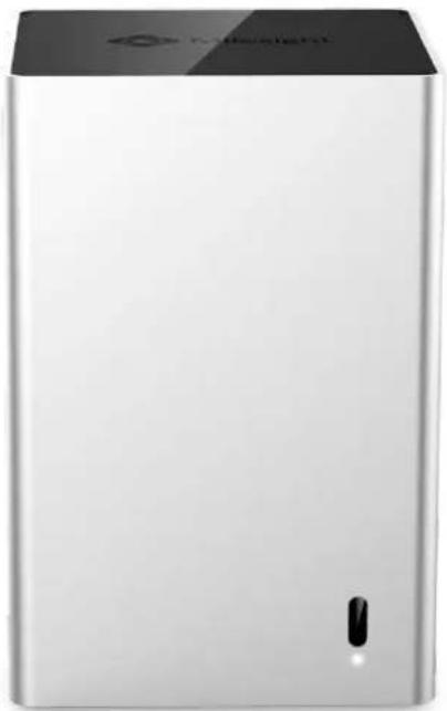
natural_image
Exterior view of a silver cylindrical device with a black top and small black button (no visible text or symbols)(2) MS-N5000 Series: MS-N5008/MS-N5016
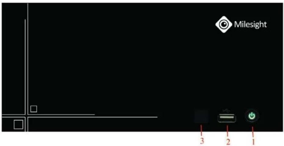
text_image
Milesight 1 2 3| NO. | Item | Description |
| 1 | Power | Power NVR on/off. |
| 2 | USB Ports | USB ports for additional devices such as USB mouse, keyboard and USB flash drive. |
| 3 | IR Receiver | Receiver for IR signal. |
(3) MS-N7000 Series: MS-N7016
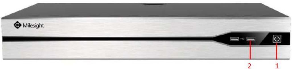
text_image
Milesight 2 1| NO. | Item | Description |
| 1 | Power | Power NVR on/off. |
| 2 | USB Ports | USB ports for additional devices such as USB mouse, keyboard and USB flash drive. |
(4) MS-N8000 Series: MS-N8016
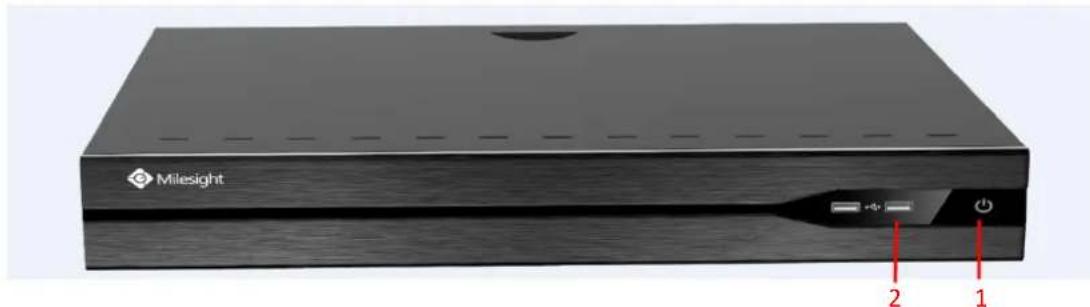
text_image
Milesight 2 1File Format: MS-QR-JS-04 Rev1.0 Durability Date: 1Years
| NO. | Item | Description |
| 1 | Power | Power NVR on/off. |
| 2 | USB Ports | USB ports for additional devices such as USB mouse, keyboard and USB flash drive |
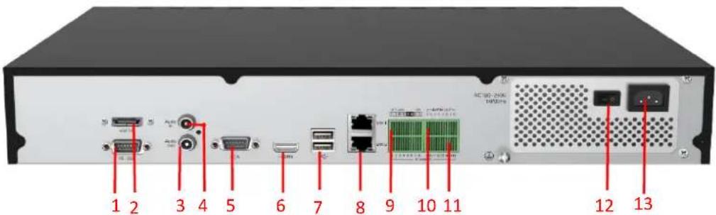
text_image
1 2 3 4 5 6 7 8 9 10 11 AC-100-2000 12 13| NO. | Item | Description |
| 1 | RS-232 | Interface for console. |
| 2 | eSATA | Interface for external HDD. |
| 3 | Audio In | RCA connector for audio input. |
| 4 | Audio Out | RCA connector for audio output synchronized with video output. |
| 5 | VGA | DB9 connector for VGA output with local video output a menu displayed. |
| 6 | HDMI | HDMI video output connector. |
| 7 | USB Ports | USB ports for additional devices such as USB mouse, keyboard and USB flash drive. |
| 8 | RJ45 Port | Interface for Ethernet. |
| 9 | RS-485 Port | Interface for RS-485 devices. T+, T- pin connects to PT |
| 10 | Alarm Out | Interface for alarm out (4 channels). |
| 11 | Alarm In | Interface for alarm input (16 channels). |
| 12 | Power | Power NVR on/off. |
| 13 | AC 100-240V | AC 100-240V 50/60Hz power supply. |
(5) MS-N5000-UH Series: MS-N5016-UH/MS-N5032-UH
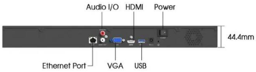
text_image
Audio I/O HDMI Power 44.4mm Ethernet Port VGA USB(6) MS-N7000-UH Series: MS-N7016-UH/MS-N7032-UH

text_image
Console Audio I/O HDMI Alarm I/O Ethernet Port VGA USB 66.8mm Power(7) MS-N8000-UH Series: MS-N8032-UH/MS-N8064-UH
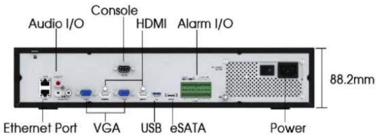
text_image
Audio I/O Console HDMI Alarm I/O Ethernet Port VGA USB eSATA Power 88.2mm(8) MS-N1000-U(P)T Series: MS-N1009-UT/MS-N1009-UPT
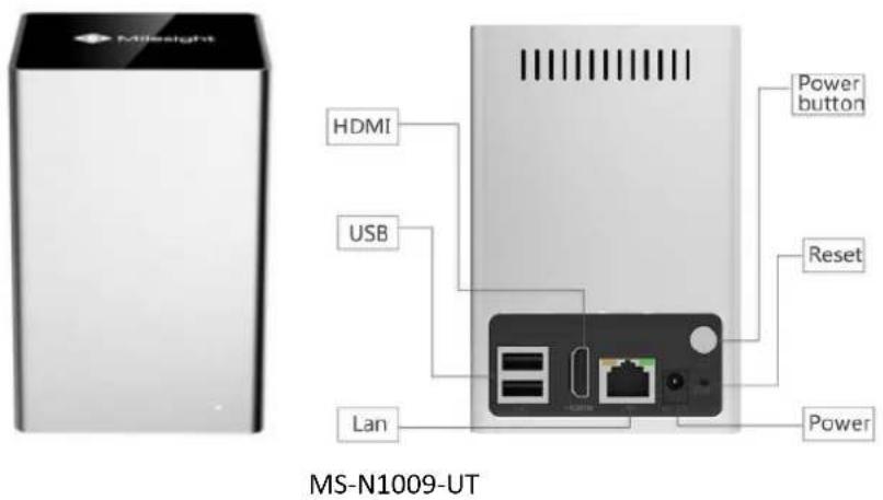
text_image
MS-N1009-UT HDMI USB Lan Power button Reset Power MS-N1009-UT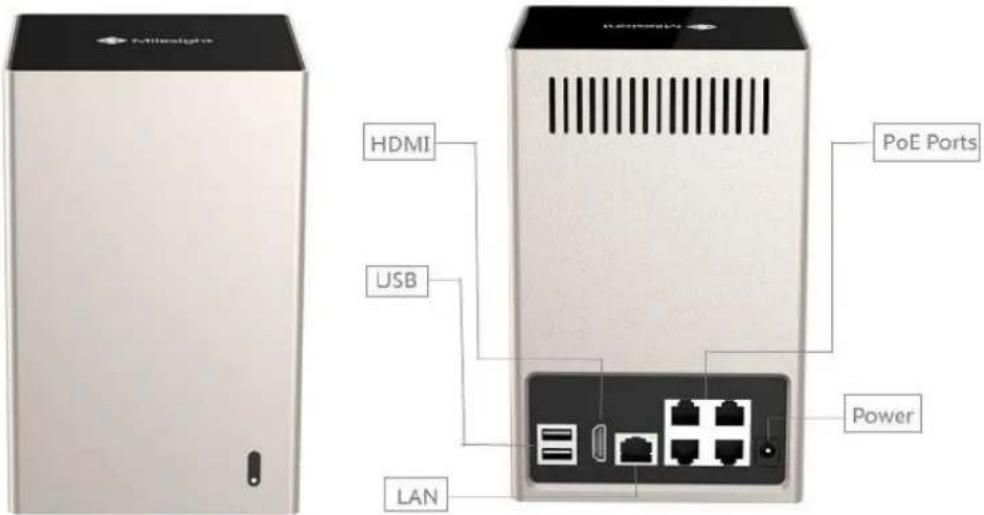
text_image
Milesight HDMI USB LAN PoE Ports PowerMS-N1009-UPT
2.2 Using a USB Mouse
| Item | Click | Description |
| Left Button | Single- click | Live view: select the channel and show the toolbar of live vMenu: select and confirm. |
| Double-click | Switch between single screen to multi-screen when in live vi mode and playback mode. | |
| Click and drag | (1) Control rotation direction in PTZ mode.(2) Set the target area in tamper-proof, motion detection an privacy mask alarm settings.(3) Drag the digital zoom area.(4) Drag the channel and the time scroll bar. | |
| Right Button | Single-click | Live view: shows pop-up menu.Menu: exit and go to previous menu. |
| Scroll-wheel | Scroll up | Scroll up the page. |
| Scroll down | Scroll down the page. |
2.4 IR Remote Controller
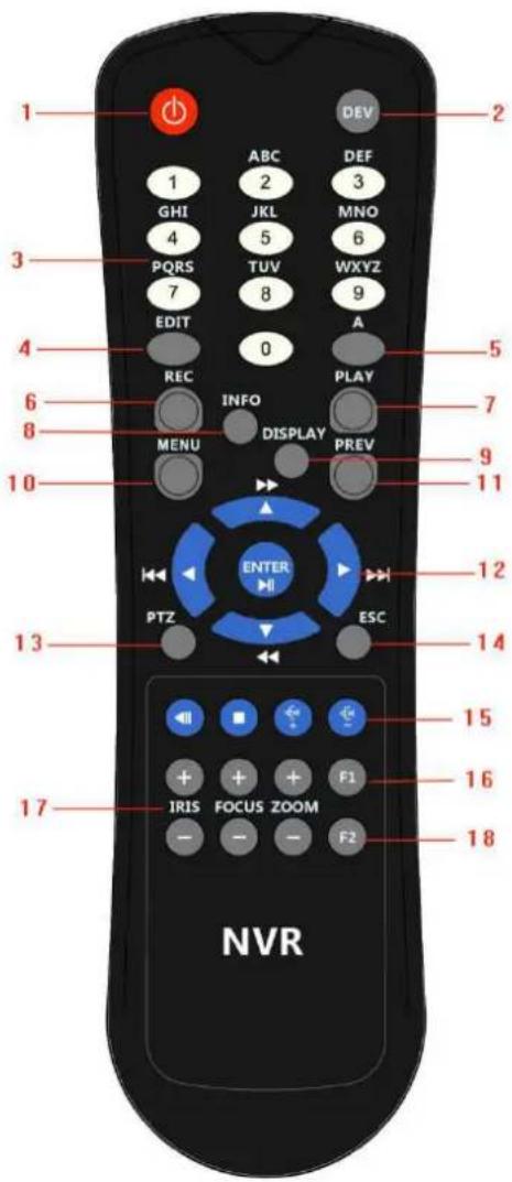
text_image
1 2 3 4 5 6 7 8 9 10 11 12 13 14 15 16 17 NVR ABC DEF GHI JKL MNO 4 5 PQRS TUV WXYZ 7 8 9 EDIT 0 A REC INFO PLAY MENU DISPLAY PREV ENTER PTZ ESC F1 + + + + F2 - - - -F-2.4.1
| NO | Name | Description |
| 1 | Power | Power on/off the NVR |
| 2 | DEV | Enables/disables remote control |
| 3 | ABC/123 | (1)Alphanumeric buttons are used to switch the corresponding channel in live view or PTZ Control mode.(2)Alphanumeric buttons are used to input numbers and characters edit mode. |
| 4 | EDIT | (1)Used to enter the edit status.(2)Delete the character in front of the cursor.(3)Open up the IRIS of the camera when in PTZ status. |
| 5 | A | (1)Switch the input methods including figure, letters and symbols.(2)Auto scan when in PTZ control. |
| 6 | REC | (1)The REC/SHOT button is used to enter recording configuration interface.(2)When controlling a PTZ, press the REC/SHOT Button to invoke pr positions.(3)Open and close sound system when playback. |
| 7 | PLAY | (1)Enter the playback interface.(2)Auto scan when in PTZ control. |
| 8 | INFO | Zoom control when in PTZ control. |
| 9 | DISPLAY | (1)Switch between main and spot output.(2)To zoom the camera in PTZ mode. |
| 10 | MENU | (1)Enter the main menu interface.(2)Display/cover playback toolbar when in playback status.(3)Open/close the sound of front panel by pressing and holding mo than 3 seconds. |
| 11 | PREV | (1)Used to switch between single screen and multi-screen mode.(2)Adjust the focus in PTZ mode. |
| 12 | DIRECTION/ENTER | (1)Move the active selection in a menu, select menu items setting.(2)Up/down button stands for single frame fast forward/playback, left/right button stands for speed up/slow down the video.(3)Switch live view channel or screen in live view mode.(4)Move the PTZ when in PTZ control. |
| 13 | PTZ | (1)Confirm selection in menu modes.(2)Switch to tick checkbox and ON/OFF.(3)In playback mode, can be used to play or pause the video.(4)In cruise mode, press to pause/restart the cruise. |
| 14 | ESC | Same as ESC button on front panel |
| 15 | RESERVED | Reserve the settings |
| 16 | F1 | (1)Select all items on the list.(2)Control light status when in PTZ control.(3)Switch to playback or sequence play in playback status |
| 17 | PTZ CONTROL | To adjust the iris, focus and zoom of a PTZ camera. |
| 18 | F2 | The F2 button is used to switch menu attribute page. |
2.5 Hard Disk Installation
2.5.1 MS-N7000 series Hard Disk Installation
Step1. Unscrew the back and both sides' screws to open the upper lid.
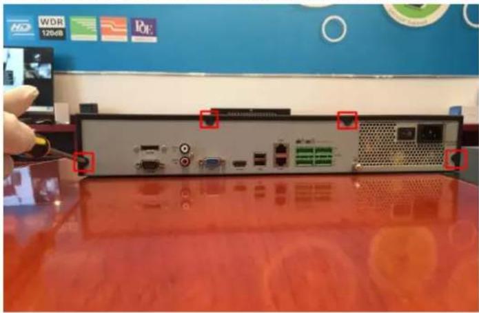
natural_image
Back view of a computer rack with ports and connectors, placed on a red surface (no visible text or symbols)F-2.5.1
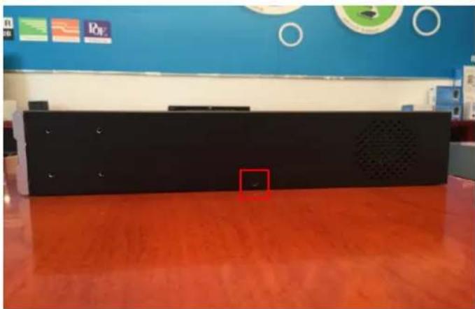
natural_image
Interior view of a modern office or service hall with blue walls, red flooring, and wall-mounted circular displays (no visible text or symbols)F-2.5.2
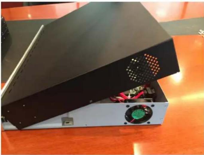
natural_image
Exterior view of a black electronic device with a fan and power outlet, placed on an orange table (no visible text or symbols)F-2.5.3
Step2. Install the hard disks into NVR with screws shown in below pictures. (SATA Slots of hard disk should be toward inside NVR.)

natural_image
Interior view of an electronic control panel with visible circuit board, cables, and connectors (no text or symbols)F-2.5.4
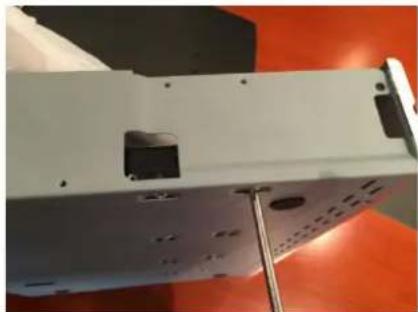
natural_image
Close-up of a white electronic device with mounting holes and a metallic stand, set against an orange background (no visible text or symbols)F-2.5.5
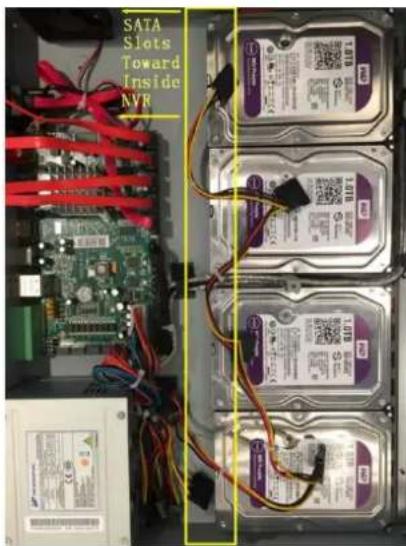
text_image
SATA Slots Toward Inside NVRF-2.5.6
Step3. Join the power and data connectors to corresponding hard disk.
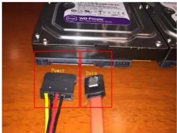
text_image
WO Purple Power DataF-2.5.7
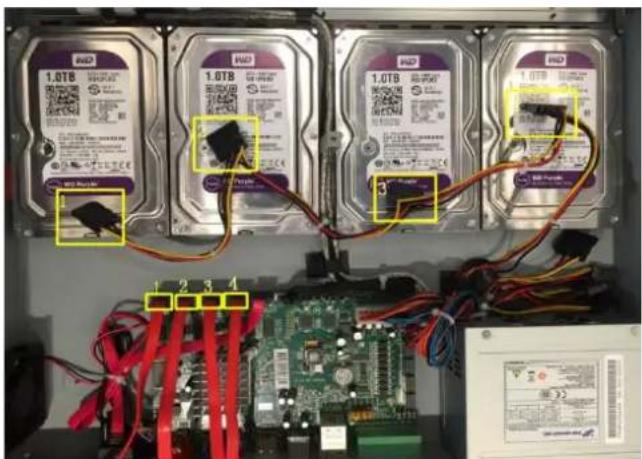
text_image
1.078 1.078 1.078 1.078 1.078 1.078 1.078 1.078 1 2 3 4F-2.5.8
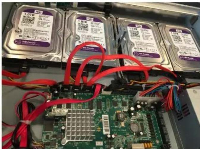
natural_image
Close-up of an internal circuit board with multiple hard drives and red cables connected to a green circuit board (no readable text or symbols)F-2.5.9
2.5.2 MS-N8000 series Hard Disk Installation
Step1. Unscrew the back and both sides' screws to open the upper lid.
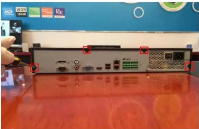
natural_image
Back view of a network equipment unit with ports and connectors, placed on a red surface (no visible text or symbols)F-2.5.10
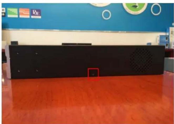
natural_image
Interior view of a modern office or lab space with blue walls, orange flooring, and a black electronic device panel (no visible text or symbols)F-2.5.11
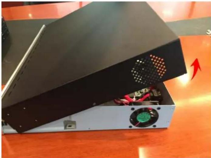
natural_image
Exterior view of a black electronic device with a fan and power outlet, placed on an orange table (no visible text or symbols)F-2.5.12
Step2. Uninstall the upper hard disk panel.
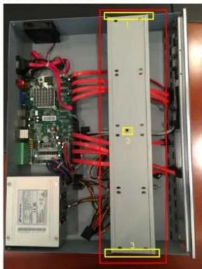
natural_image
Interior view of an electronic control panel with visible circuit board, RAM, and red cables (no text or symbols)F-2.5.13
Step3. Install the hard disks into NVR with screws shown in below pictures.(SATA slots of hard disks should be toward inside NVR)
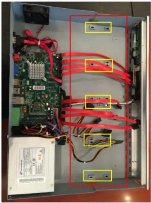
natural_image
Interior view of an electronic device showing a circuit board, power supply, and red-labeled connectors (no readable text or symbols)F-2.5.14
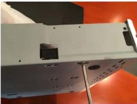
natural_image
Exterior view of a white electronic device with mounting holes and a metallic stand (no visible text or symbols)F-2.5.15
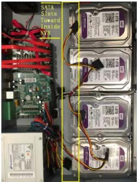
text_image
SATA Slots Toward Inside NVRF-2.5.16

text_image
SATA Slot Toward Inside NVRF-2.5.17
Note:
The SATA slots are in SHORT HALF side and the SATA slot toward inside NVR.
Step4. Join the power connectors to corresponding hard disks.(Install lower hard disk panel before upper one)
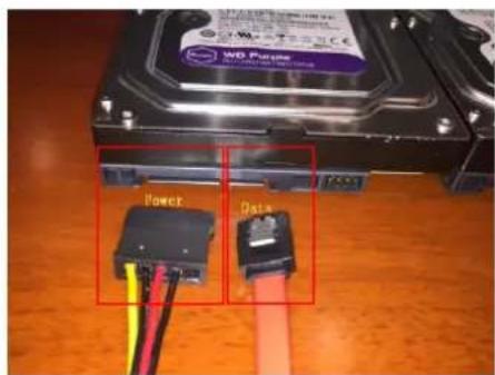
text_image
WO Piase Power DataF-2.5.18
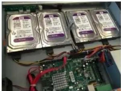
natural_image
Interior view of an ATM drive bay with four hard disk drives and a circuit board (no visible text or labels)F-2.5.19
Step5. Join the data connectors to corresponding hard disk.(Check the connection by below sequence)
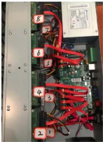
text_image
Internal wiring diagram showing numbered components on a computer motherboard with visible connections and labelsF-2.5.20
Note:
The data connector sequence of MS-N7000 series is different from MS-N8000 series'.
3. Local Operation
3.1 Wizard Setting
By default, the Setup Wizard will start once the NVR has loaded. The Setup Wizard will guide you to complete important settings to make sure the device function well. You can choose if the Setup Wizard starts or not every time when the device powered.
Please complete the configuration as following:
Step1. Input the user name and password;
If you want to modify the admin password, input the new password.
Note:
-
If the NVR firmware version out of the factory is xx.7.0.6 or above, the default user name is "admin" and the default password is "ms1234";
-
If the NVR firmware is upgraded to xx.7.0.6 or above from a lower version, the default password will turn to "ms1234" after a reset, or it will keep the old default password "123456";
-
If the NVR firmware version is below xx.7.0.6, the default user name is "admin" and the default password is "123456".

text_image
Wizard Admin Password ****** ✓ New Admin Password New Password ****** Confirm ****** Start wizard when device starts? Back Next CancelF-3.1.1
Step2. Date and time setting
Select the Time Zone and Date Format or you can set date and time manually.
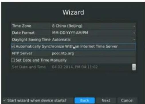
text_image
Wizard Time Zone 8 China (Beijing) Date Format MM-DD-YYYY-AM/PM Daylight Saving Time Automatic Automatically Synchronize With an Internet Time Server NTP Server pool.ntp.org Set Date and Time Manually Set Date and Time 04.02.2014. PM 04:11:02 Start wizard when device starts? Back Next CancelF-3.1.2
Step3. Network setting
Input the IP Address, Subnet Mask, Gate Way and Preferred DNS Server. Internal NIC IPv4
Address option is only for PoE NVR.
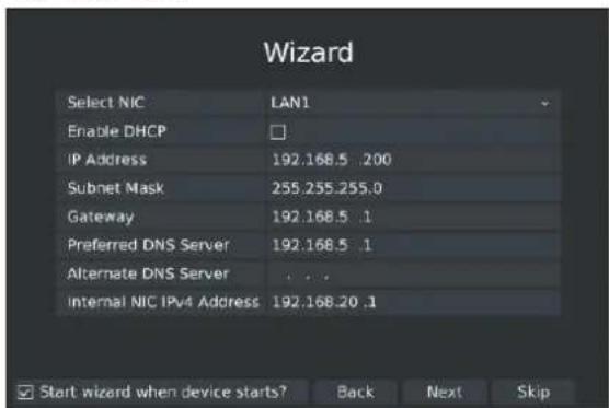
text_image
Wizard Select NIC LAN1 Enable DHCP IP Address 192.168.5 .200 Subnet Mask 255.255.255.0 Gateway 192.168.5 .1 Preferred DNS Server 192.168.5 .1 Alternate DNS Server ... Internal NIC IPv4 Address 192.168.20 .1 Start wizard when device starts? Back Next SkipF-3.1.3
Step4. Disk Management
Detect the hard disk installed in the NVR automatically, support format hard disk in this page.
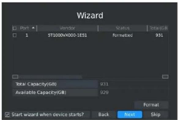
text_image
Wizard Port Vendor Status Total(GB) 1 ST1000VX000-1ES1 Formatted 931 Total Capacity(GB) 931 Available Capacity(GB) 929 Format Start wizard when device starts? Back Next SkipF-3.1.4
Step5. Camera Management
Search all the cameras in LAN, select camera to add. Support to detect the camera connected to PoE port(only for PoE NVR).
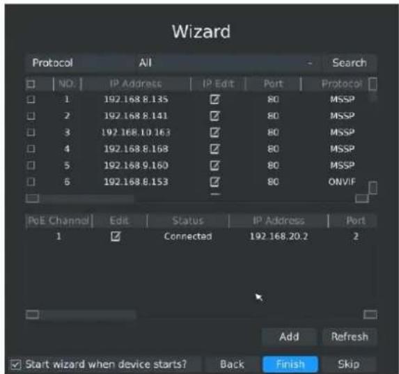
text_image
Wizard Protocol All Search NO. IP Address IP Edit Port Protocol 1 192.168 8.135 ✓ 80 MSSP 2 192.168 8.141 ✓ 80 MSSP 3 192.168 10.163 ✓ 80 MSSP 4 192.168 8.168 ✓ 80 MSSP 5 192.168 9.160 ✓ 80 MSSP 6 192.168 8.153 ✓ 80_ONVIF PoE Channel Edit Status IP Address Port 1 ✓ Connected 192.168.20.2 2 Add Refresh Start wizard when device starts? Back Finish SkipF-3.1.5
Step6. Login
Input the user name and password.
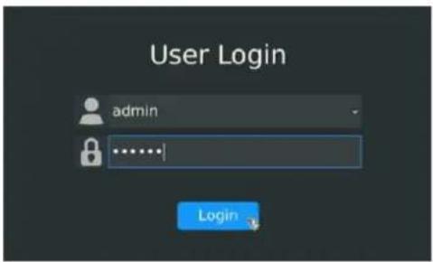
text_image
User Login admin LoginF-3.1.6
3.2 Playback
To play and backup the recorded files in specified time period.
3.2.1 Video Playback
It can support playback according to recorded time. Play recorded files in specified time period; synchronous playback of multi-channels is supported.
Step1. Enter Video Playback Interface shown in F-3.2.1 by clicking Main→Playback→

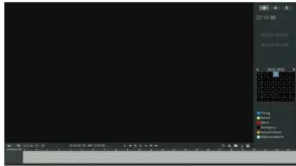
text_image
Screenshot of a software interface with tool panels and a grid workspace, showing menu options like 'Open', 'Close', 'Help', etc.F-3.2.1
Step2. Select a desired channel and date
Select playback layout and channel. Click the date in red when there are recorded files of the selected channels, the record type with recording data will be show as below, and then click
to playback.
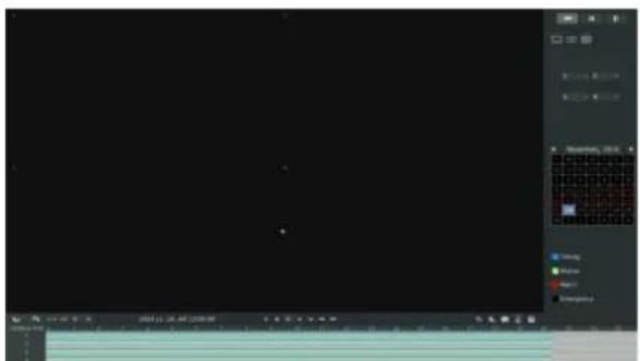
text_image
Screenshot of a software interface with tool panels and status bar, showing status indicators like 'OK', 'Cancel', and 'Help'.F-3.2.2
Note:
-
The day in red has recording files; please select the date in red to playback.
-
16 channels can be selected to playback synchronously.
Video Playback Tool Bar Description

text_image
2014.11 24 AM 17:00:00 1 2 3 4 5 6 7 8 9 10 11 12 13 14 15 16 17 18 19 20 21 22 23The tool bar can display multi-event record. It shows that in this record period what kind of event has happened. The symbolic meaning of each color is shown below:
Blue—Timing Green --- Motion
Red --- Alarm Black --- Emergency
And take this bar above for example, it means in this recording period there are motion and timing event which have triggered.
| Button | Description | Button | Description | Button | Description | Button | Description |
 | Rewind |  | Stop |  | Play |  | Pause |
 | Reverse Step |  | Forward Step |  | Fast Backward |  | Fast Forward |
 | Previous 4 Cams |  | Next 4 Cams |  | Timeline Backward |  | Timeline Forward |
 | Timeline Zoom In |  | Timeline Zoom Out |  | Timeline |  | Playback Position |
 | Timeline Cutting |  | Timeline Cut Off |  | Audio On |  | Audio Off |
 | Snapshot |  | Backup |
3.2.2 Video Files Backup
Regular recorded files can be backed up by various devices, such as USB flash drives (USB flash disk, USB HDD, USB writer), eSATA etc.
Step1. Enter video playback interface by clicking Main menu→Playback→
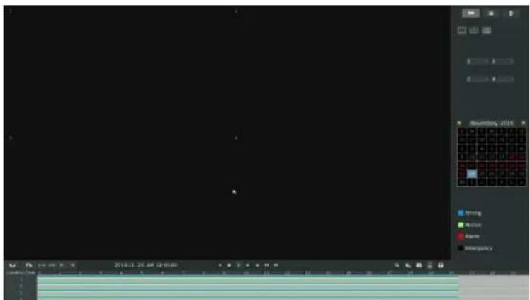
text_image
2016.11 25:00 12:00:00 EmergencyF-3.2.3
Step2. Select Recorded files for Backup
Select the channel and date you want to backup, then select the start time at time line and click

it will change into which means cut begins.

text_image
2014.12.04. AM 4:42:17 CAMERA TIME 0 1 2 3 4 5 6 7 8 9 10 11 12 13 14 15 16 17 18 CutF-3.2.4
Select the end time at time line and click , it will change into which means cut ends.

text_image
CAMERA/TIME 0 1 2 3 4 5 6 7 8 9 10 11 12 13 14 15 16 17 18 19 1 2 3 4 2014.12.04. AM 6:47:00F-3.2.5
Step3. Click enters to backup interface, select Backup media and click [Backup].
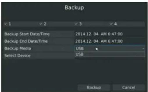
text_image
Backup ✓ 1 ✓ 2 ✓ 3 ✓ 4 Backup Start Date/Time 2014.12.04.AM 6:47:00 Backup End Date/Time 2014.12.04.AM 6:47:00 Backup Media USB Select Device USB Backup CancelF-3.2.6
Step4. The pop-up window will prompt: Please wait...
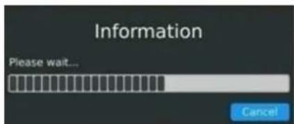
text_image
Information Please wait... CancelF-3.2.7
Step5. When all backup files have been exported, 'Backup Success' will be prompted.
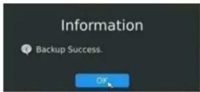
text_image
Information Backup Success. OKF-3.2.8
3.2.3 Picture Playback
Search and look for the snapshot files saved in HDD.
Step1. Enter Picture Playback Interface by clicking Main menu→Playback→
Select a desired channel, start time and end time, click [Search]
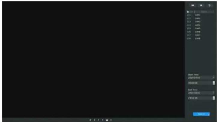
text_image
Start Time 2016-04-03 9:00:00:00 End Time 2016-04-02 28:00:00F-3.2.9
Step2. Enter Picture Info List and look up the pictures.
Click to play the desired pictures, or click to auto play the picture.
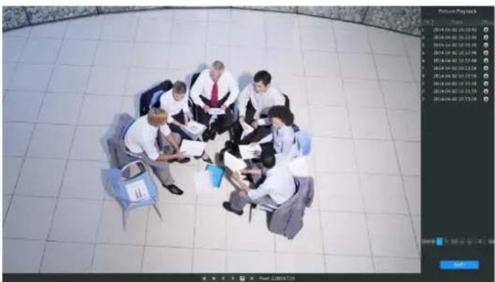
natural_image
Overhead view of five people sitting in a circle on a tiled floor, reviewing documents (no visible text or symbols)F-3.2.10
Picture Playback Tool Bar Description

| Button | Description | Button | Description | Button | Description | Button | Description |
 | Backward Play |  | Play |  | Previous Picture |  | Next Picture |
| Backup pictures | Close |
3.2.4 Picture Files Backup
Step1. Select pictures you want to backup in picture playback interface.
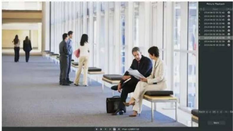
text_image
Photo of business people waiting in a modern airport corridor with overlaid UI panel showing daily data and camera settingsF-3.2.11
Step2. Select backup media and click to save picture.
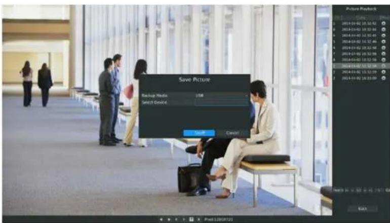
text_image
Save Picture Backup Media USB Select Device Save CancelF-3.2.12
3.3 Camera Settings
Before configuration, please ensure that the IP device is connected to the same network as your NVR and that the network setting for your NVR is properly setup.
3.3.1 Camera Management
Step1. Enter camera management interface by clicking main menu → Camera → Camera Management to enter camera management interface.
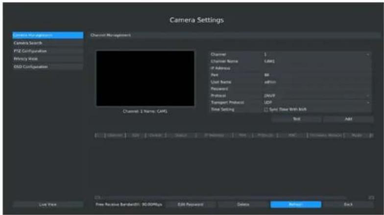
text_image
Camera Settings Camera Management Camera Search PTZ Configuration Privacy Mode GSD Configuration Channel Management Channel 1 Name: CAMS Channel 1 Channel Name: CAMS IF Address Port: 86 User Name: admin Protocol: 200V Transport Protocol: UDP Time Setting: Sync Timer With NVR Reset Add Lock Time Free Receive Bandwidth: 90.00MHz Edit Password: Delete Refresh BackF-3.3.1
Step2. Add IP Channel
Method1. Add IP Channel in camera search interface
- Enter camera search interface by clicking Main Menu → Camera → Camera Search.
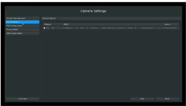
text_image
Camera Settings Camera Management PV2 Configuration PV2 Head USB Configuration Camera Search Profile: UNM Search Add Back View ViewF-3.3.2
- Click [search] button to quickly search the IP devices in LAN with different types: All, ONVIF, MSSP.
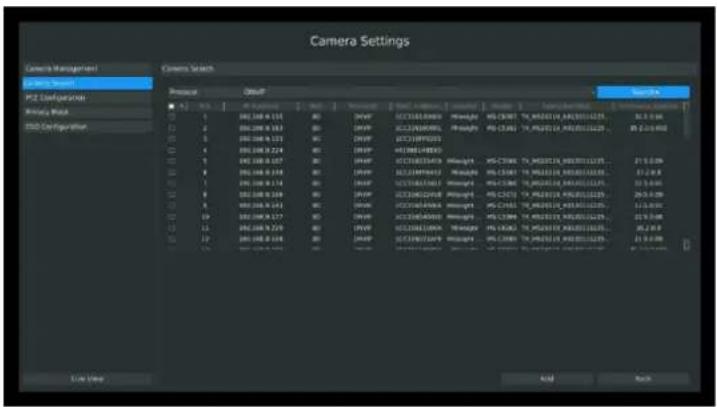
text_image
Camera Settings Camera Management Camera Search ISO Configuration ISO Mask ISO Configuration Camera Search ISO 2.0000 ISO 2.0010 ISO 2.0000 ISO 2.0010 ISO 2.0000 ISO 2.0010 ISO 2.0000 ISO 2.0010 ISO 2.0000 ISO 2.0010 ISO 2.0000 ISO 2.0010 ISO 2.0000F-3.3.3
- Double click the channel, input password and click [Add] button.
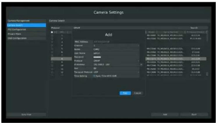
text_image
Camera Settings Camera Management Camera Search PTZ Configuration Private Port SOD Configuration Camera Smooth Protocol Add Add Address: 100 MHz/100 MHz Channel: 0 Name: CACU User Name: Alluvial Protocol: 00000000000000000000000000000000000000000000000000000000000000000000000000000000000000Attribute: 192.546.3.1.1.1.1.1.1.1.1.1.1.1.1.1.1.1.1.1.1.1.1.1.1.1.1.1.1.1.1.1.1.1.1.1.1.1.1.1.1.1.1.1.1.1.1.1.1.1.1.1.1.2
Port: 88 Transcet Protocol: UCP Time Setting: 5ms, Time shift: 5ms Add Cancel Add Add BackF-3.3.4
Or Check to bulk adding the IP cameras if they are with same password.
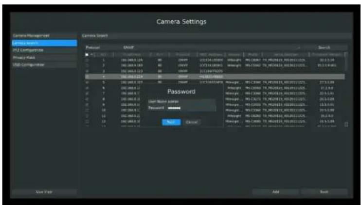
text_image
Camera Settings Camera Search Ptuals Couch Search 1 2 3 4 5 6 7 8 9 10 11 12 13 14 15 16 17 18 19 20 21 22 23 24 25 26 27 28 29 30 31 32 33 34 35 36 37 38 39 40 41 42 43 44 45 46 47 48 49 50 51 52 53 54 55 56 57 58 59 60 61 62 63 64 65 66 67 68 69 70 71 72 73 74 75 76 77 78 79 80 81 82 83 84 85 86 87 88 89 90 91 92 93 94 95 96 97 98 99 100 Password: User Name name: Password: Name: Close: Add... BackF-3.3.5
Method2. Add IP Channel in camera management interface
- Enter camera management menu by clicking Main Menu → Camera → Camera Management
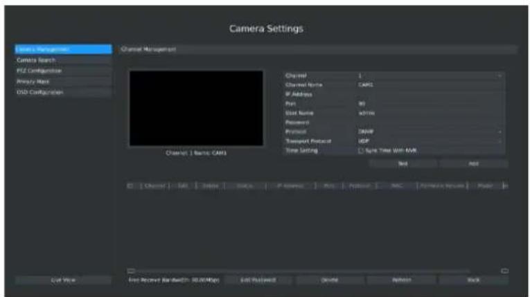
text_image
Camera Settings State Management Camera Search FIZ Configurations Proxy Rate OSI Configurations Channel Management Channel 1 Basic: CAMS Channel 1 Channel Name: CAMS IF Address: Port: 80 Unit Name: d3706 Protocol: Protocol: 2448 Transport Protocol: UDP Time Setting: Split Time Visit: 5448 Test Add Edit View Free Record Bandwidth: 90.00 Mbps Edit Platform Delete Refresh BackF-3.3.6
- Select idle channel then input complete information, click [Add] button.
There are three protocols available for camera connection:
● ONVIF: Add the camera with ONVIF protocol, you can add any IP cameras with ONVIF compatible if select this protocol. The detail formats are shown in F-3.3.7;
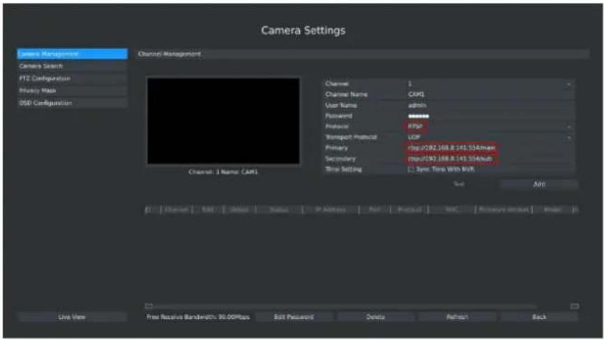
- RTSP: Use RTSP to add camera. You can add any IP cameras which have RTSP protocol streams. You need select 554 for the port and input the resource path for the camera. Take Milesight device for example, for main stream the resource path is "rtsp://IP:port/main" and the second stream is "rtsp://IP:port/sub". The details about adding format are shown in F-3.3.8;
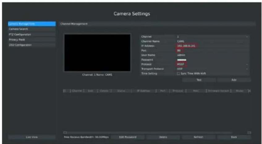
- MSSP: If your IP camera is a Milesight device, you can select this protocol to add cameras. The detail formats are shown in F-3.3.9;
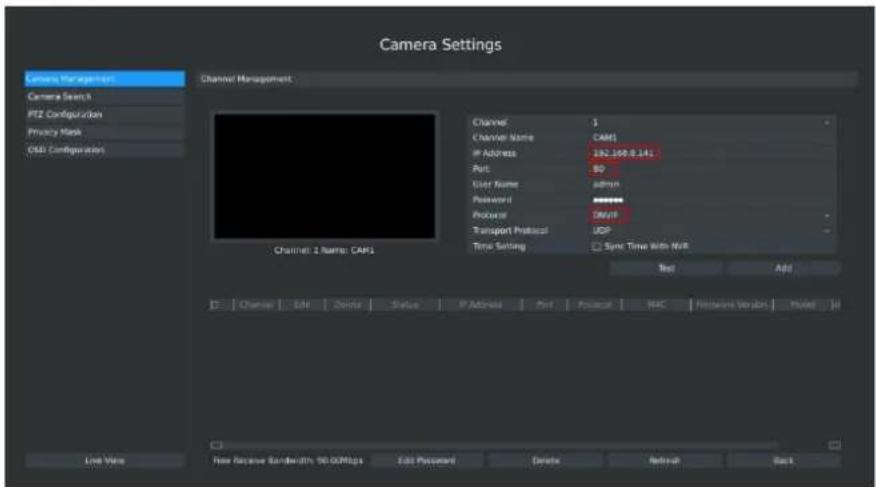
text_image
Camera Settings Camera Management Camera Search PIZ Configuration Privacy Mask OBS Configuration Channel Management Channel 2 Name: CAM1 Channel: 3 Channel Name: CAM1 IF Address: 192.100.8.141 Port: 50 User Name: admin Password: ******** Protocol: DWG Transport Protocol: UDP Time Setting: Sync Time With NVR Test Add Live View Free Receive Bandwidth: 90.00Mbps Edit Password Delete Refresh BackF-3.3.7 ONVIF
text_image
Camera Settings Camera Management Camera Search PTZ Configuration Privacy Mask DGT Configuration Channel Management Channel 1 Name: CAMS Channel 2 Channel Name: CAFE User Name: admin Pavamid: ******** Protocol: RSP Transport Protocol: USB Primary: http://192.168.8.141.554Main Secondary: http://192.168.8.141.554Sub True Setting: Sync Time With MVR Text: Add File Edit Print Status IP Address Print Format Web Capture Version Help Live View Press Receive Bandwidth: 90.00Mbps Edit Password Delete Refresh BackF-3.3.8 RTSP
text_image
Camera Settings Camera Management Camera Search PT2 Configuration Privacy Mask OSD Configuration Channel Management Channel Name: CAM1 IP Address: 192.168.0.141 Port: 80 User Name: admin Password: ****** Protocol: MSIP Transport Protocol: OSIP Time Setting: Sync Time with USB Test Add Channel 1 Name: CAM1 Last view Free Receive Bandwidth: 30.00Mbps Edit Password Delete Refresh BackF-3.3.9 MSSP
Step3. Check the connection status
After adding the IP channels, click [Refresh] button, the [status] will show [connected] as below. If not, you need to check if the network is connected or whether the user name, password is correct or not.
| Channel | Edit | Delete | Status | IP Address | Port | Protocol | MAC | Vendor | Model |
| 1 | ✓ | ✓ | Connected | 192.168.5.168 | 80 | ONVF | 1cc31604014e | Milesight T...gy Co.,Ltd. | MS-C3366 |
| 2 | ✓ | ✓ | Connected | 192.168.5.169 | 80 | ONVF | 1cc316020046 | Milesight T...gy Co.,Ltd. | MS-C3658 |
| 3 | ✓ | ✓ | Connected | 192.168.5.153 | 80 | ONVF | 1cc31601024f | Milesight T...gy Co.,Ltd. | MS-C2662 |
| 5 | ✓ | ✓ | Connected | 192.168.5.191 | 80 | ONVF | 1cc316020059 | Milesight T...gy Co.,Ltd. | MS-C3658 |
| 6 | ✓ | ✓ | Connected | 192.168.5.192 | 80 | ONVF | 1cc31602002b | KAREL | NBE-213RA-24 |
| 7 | ✓ | ✓ | Connected | 192.168.5.192 | 80 | ONVF | 1cc316080009 | Milesight T...gy Co.,Ltd. | MS-C3662 |
F-3.3.10
Step4. Configure IP Channel
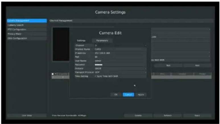
- After successfully adding the channel, click or double-click this channel to re-edit the channel info, address, and password, etc.
text_image
Camera Settings Channel Management Camera Search PFE Configuration Proxy Mesh Data Configuration Channel Management Camera Edit Settings Parameters Channel 3 Channel Name:CARS IP Address 252 198.3.166 Path 80 User Name:dsmn Racusing ######### Instance ONUP Managed Protocol:UCP Time Setting:-Save Time With NWR OK Cancel Apply Last View Free Service Demodality: ADRings Cancel Refresh SalesF-3.3.11
Note:
By default, the user name and password entered here are the default user name and password. The management port is 80 and the default Transport protocol is UDP.
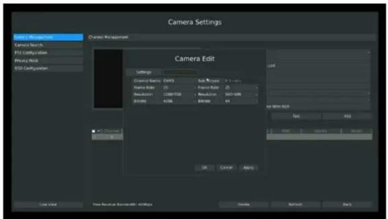
- Select [Parameters] attribute page to re-edit this channel parameters. Click [Save] to save the configuration
text_image
Camera Settings Line 1: Mousecraft Camera Search FX Configuration Privacy Mesh ISO Configuration Channel Management Camera Edit Settings Channel Name: CAT3 Sub-Frame: 2.0 Name Rate: 25 Frame Rate: 25 Resolution: 1289/726 Resolution: 042-1698 Distance: 6.0K Distance: 64 View View Free Broadcast Broadcast: 400Mbps OK Cancel Apply Add Save... Remove... Close Networks... BackF-3.3.12
- You can delete this IP channel by clicking, or you can multi-select the devices and then
Delete click to delete(PoE channel does not support deleting).

text_image
Channel Edit Delete Status IP Address Port Protocol MAC Vendor Market 1 ✓ ✓ Connected 192.168.B.168 80 ONVIF 1CC316022C92 Milesight T...gy Co.,Ltd. MS-C3596 2 ✓ ✓ Connected 192.168.B.169 80 ONVIF 1CC3160112DF Milesight T...gy Co.,Ltd. MS-C2182 3 ✓ ✓ Connected 192.168.B.172 80 ONVIF 1CC3160A0160 Milesight T...gy Co.,Ltd. MS-C3602 4 ✓ ✓ Connected 192.168.B.170 80 ONVIF 1CC316020032 Milesight T...gy Co.,Ltd. MS-C3658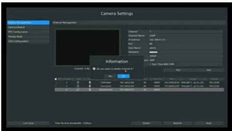
text_image
Camera Settings Edit's Settings Camera Search MSI Configuration History Risk MSI Configuration Channel Management Channel Name IP Address Run User Name Microsoft DWF GDP - Specific Time MSI (R/W) Status: No Information Chancen 0 No Do you want to delete channel 0 ? No OK Connected 192.486.3.268 Connected 192.348.6.269 Connected 192.348.6.270 Connected 192.348.6.271 Change 2 Load 1 USB 368.8.173 80 admin adminb DWIP SDF GDP - Specific Time MSI (R/W) Next Add Live View Free Receive Bandwidth 25MHz Delete Refresh BackF-3.3.13
Step5. Configure PoE Channel(Only for PoE NVR)
- Connect camera to PoE port, it will detect the camera automatically.
- If the camera's password is "ms1234", it will change the camera into the same network segment with internal NIC IPv4 address and then the camera will be connected automatically.
- If the camera's password is not "ms1234", it will show disconnected status in the PoE channel.
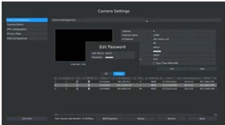
You can edit the channel's password by click
multi-select the devices and then click this button to modify). Change the channel's password to camera's password, then it will change the camera into the same network segment with internal NIC IPv4 address and then the camera will be connected automatically.
text_image
Camera Settings Channel Management Camera Touch PZ Comparations Privacy Map EXO Comparations Channel Channel Name: LAMA If Address: 102.168.1.43 B0 ADDRESS Password User Name: admin Password: ******** OK Cancel Add File View Pass Passive Bandwidth: 75.00Mbps Edit Password Delete Refresh BackF-3.3.14
3.3.2 Camera Search
You can search and add IP cameras here
Step1. Enter camera search interface by clicking Main menu→Camera→Camera Search
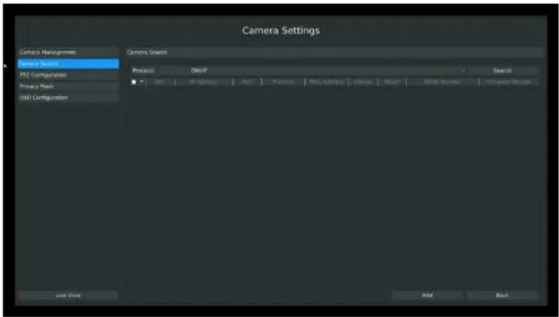
text_image
Camera Settings Camera Management Camera Search PT2 Composites Privacy Mask OEM Composites Camera Search Protocol OpenP Search Use View Add BackF-3.3.15
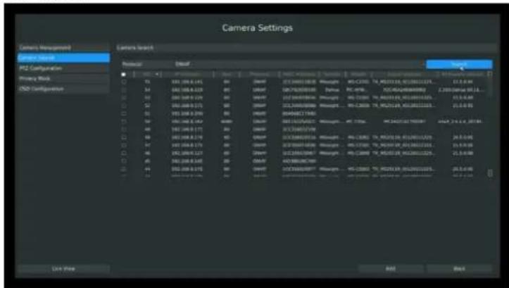
Step2. Click [search] to quickly search the IP devices in LAN, you can choose different type to search: All, ONVIF, MSSP.
text_image
Camera Settings Camera Management Camera Search P2 Configuration Privacy Block CSD Configuration Protocol Default View Preview Multi-Resolution Settings Standard Signal Frequency Noise Size Frequency Frequency Frequency Frequency Frequency Frequency Frequency Frequency Frequency Frequency Frequency Frequency Frequency Frequency Frequency Frequency Frequency Frequency Frequency Frequency Frequency Frequency Frequency Frequency Frequency Frequency Frequency Frequency Frequency Frequency Frequency Frequency Frequency Frequency Frequency Frequency Frequency Frequency Frequency Frequency Frequency Frequency Frequency Frequency Frequency Frequency Frequency Frequency Frequency Frequency F10000000000000000000000000000000000000000000000000000000000000000000000000000000000000000000000000000 15 15 15 15 15 15 15 15 15 15 15 15 15 15 15 15 15 15 15 15 15 15 15 15 15 15 15 15 15 15 15 15 15 15 23.4.48 15 15 15 15 15 15 15 15 15 15 15 15 15 15 15 15 15 15 15 15 15 15 15 15 15 15 15 15 15 15 15 15 15.4.48 15 15 15 15 15 15 15 15 15 15 15 15 15 15 15 15 15 15 15 15 15 15 15.4.48 15 15 15 15 15 15 15 15 16.4.48 15 23.4.48.4.48.4.48.4.48.4.48.4.48.4.48.4.48.4.48.4.48.4.48.4.48.4.48.4.48.4.48.4.48.4.48.4.48.4.48.4.48.4.46.46.46.46.46.46.46.46.46.46.46.46.46.46.46.46.46.46.46.46.46.46.46.46.46.46.46.46.46.46.46.46.46.46. F22 F22 F22 F22 F22 F22 F22 F22 F22 F22 F22 F22 F22 F22 F22 F22 F22 F22 F22 F22 F22 F22 F22 F22 F22 F22 F22 F22 F22 F22 F22 F22 F22 F22 F39 F39 F39 F39 F39 F39 F39 F39 F39 F39 F39 F39 F39 F39 F39 F39 F39 F39 F39 F39 F39 F39 F39 F39 F39 F39 F39 F39 F39 F39 F39 F39 F39 F39 G77 G77 G77 G77 G77 G77 G77 G77 G77 G77 G77 G77 G77 G77 G77 G77 G77 G77 G77 G77 G77 G77 G77 G77 G77 G77 G77 G77 G77 G77 G77 G77 G77 G77 A B B B B B B B B B B B B B B B B B B B B B B B B B B B B B B B B B B B B B B B B B B B B B B B B B B B B B B B B B B B B B B B B B B B B B B B B B B B B B B B B B B B B B B B B B B B B B B B B B B B B BB BB BB BB BB BB BB BB BB BB BB BB BB BB BB BB BB BB BB BB BB BB BB BB BB BB BB BB BB BB BB BB BB BB BB BB BB BB BB BB BB BB BB BB BB BB BB BB BB BB BB BB BB BB BB BB BB BB BB BB BB BB BB BB BB BB BB BB BB BB BB BB BB BB BB BB BB BB BB BB BB BB BB BB BB BB BB BB BB BB BB BB BB BB BB BB BB BB BB BBF-3.3.16
● ONVIF: Search the cameras that support ONVIF protocol and in the same network segment with NVR.
- MSSP: Search the Milesight cameras in LAN even with different network segments.
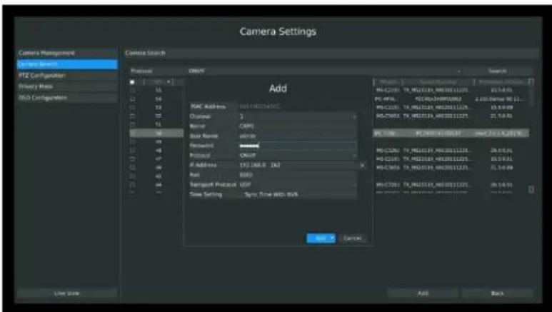
Step3. Add IP Camera
Double click the channel, input password and click [Add] button.
text_image
Camera Settings Camera Management System Search PTZ Configuration Binary Area RLO Configuration Add MAC Address 001132675456 Channel: 1 Name: CAPI Base Name: a8988 Protocol: CMSP IP Address: 192.268.9 262 Port: BBD Transcript Protocol: UDP Time Setting: Sync Flow With RMS Add Add Cancel Add Back Live StoreF-3.3.17
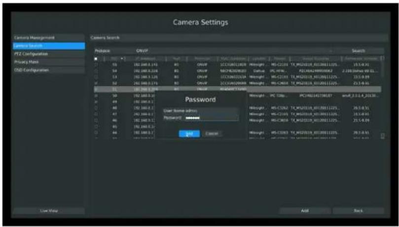
Or you can bulk adding the IP cameras if they are with same password. Click [OK] to finish bulk adding.
text_image
Camera Settings Camera Management Camera Search PTZ Configuration Privacy Mode CND Configuration Camera Search Protact ONCP Password User Name admin Password: ******** Add Cancel Search 100 50 49 48 47 46 45 44 200 100 100 100 100 100 100 100 100 100 100 100 100 100 100 100 100 100 100 100 100 100 100 100 100 100 53 52 51 50 49 48 47 46 45 44 43 42 41 40 39 38 37 36 35 34 33 32 31 30 29 28 27 26 25 24 23 22 21 20 19 18 17 16 15 14 13 12 11 10 9 8 7 6 5 4 3 2 1 Post-Adjust Status: Missight - MC-C233 TX_M2O218_XI2R01122% Default - IPC-WRC - PZC8A24W8W86J 2.2983msa W EL... Missight - MC-C233 TX_M2O218_XI2R01122% Default - IPC-C233 TX_M2O218_XI2R01122% Missight - MC-C233 TX_M2O218_XI2R01122% Default - IPC-WRC - PZC8A24W8W86J 2.2983msa W EL... Missight - IPC-WRC - PZC8A24W8W86J 2.2983msa W EL... Missight - IPC-WRC - PZC8A24W8W86J 2.2983msa W EL... Missight - IPC-WRC - PZC8A24W8W86J 2.2983msa W EL... Missight - IPC-WBC - PZC8A24W8W86J 2.2983msa W EL... Missight - IPC-WBC - PZC8A24W8W86J 2.2983msa W EL... Missight - IPC-WBC - PZC8A24W8W86J 2.2983msa W EL... Missight - IPC-WBC - PZS-77W86J 2.2983msa W EL... Missight - IPC-WBC - PZS-77W86J 2.2983msa W EL... Missight - IPC-WBC - PZS-77W86J 2.2983msa W EL... Missight - IPC-WBC - PZS-77W86J 2.2983msm a wuf_2.0.1.4_2013c... Missight - IPC-WBC - PZS-77W86J 2.2983msa W EL... Missight - IPC-WBC - PZS-77W86J 2.2983msa W EL... Missight - IPC-WBC - PZS-77W86J 2.2983msa W EL... Missight - IPC-WBC - PZS-67W86J 2.2983msa W EL... Missight - IPC-WBC - PZS-67W86J 2.2983msa W EL... Missight - IPC-WBC - PZS-67W86J 2.2983msa W EL... Missight - IPC-WBC - PZS-67W86J 2.2983mm a wuf_2.0.1.4_2013c... Missight - IPC-WBC - PZS-77W86J 2.2983msa W EL... Missight - IPC-WBC - PZS-77W86J 2.2983msa W EL... Missight - IPC-WBC - PZS-77W86J 2.2985mm a wuf_2.0.1.4_2013c... Missight - IPC-WBC - PZS-77W86J 2.2983msa W EL... Missight - IPC-WBC - PZS-77W86J 2.2983msa W EL... Missight - IPC-WBC - PZS-77W86J 2.295mm a wuf_2.0.1.4_2013c... Missight - IPC-WBC - PZS-77W86J 2.2983msa W EL... Missight - IPC-WBC - PZS-77W86J 2.2983msa W EL... Missight - IPC-WBC - PZS-77W86J 2.25mm a wuf_2.0.1.4_2013c... Missight - IPC-WBC - PZS-77W86J 2.2983msa W EL... Missight - IPC-WBC - PZS-77W86J 2.2983msa W EL... Missight - IPC-WBC - PZS-77W86J 2.26mm a wuf_2.0.1.4_2013c... Missight - IPC-WBC - PZS-77W86J 2.2983msa W EL... Missight - IPC-WBC - PZS-77W86J 2.2983msa W EL... Missight - IPC-WBC - PZS-77W86J 2.25cm a wuf_2.0.1.4_2013c... Missight - IPC-WBC - PZS-77W86J 2.2983msa W EL... Missight - IPC-WBC - PZS-77W86J 2.2983msa W EL... Missight - IPC-WBC - PZS-77W86J 2.25cm e wuf_2.0.1.4_2013c... Missight - IPC-WBC - PZS-77W86J 2.2983msa W EL... Missight - IPC-WBC - PZS-77W86J 2.2983msa W EL... Missight - IPC-WBC - PZS-77W86J 2.25cm e with e wuf_2.0.1.4_2013c... Missight - IPC-WBC - PZS-77W86J 2.2983msa W EL... Missight - IPC-WBC - PZS-77W86J 2.2983msa W EL... Missight - IPC-WBC - PZS-77W86J 2.25cm a with e wuf_2.0.1.4_2013c... Missight - IPC-WBC - PZS-77W86J 2.2983msa W EL... Missight - IPC-WBC - PZS-77W86J 2.2983msa W EL... Missight - IPC-WBC - PZS-77W86J 2.25 cm a wuf_2.0.1.4_2013c... Missight - IPC-WBC - PZS-77W86J 2.2983msa W EL... Missight - IPC-WBC - PZS-77W86J 2.2983msa W EL... Missight - IPC-WBC - PZS-77W86J 2.25cm d wuf_2.0.1.4_2013c... Missight - IPC-WBC - PZS-77W86J 2.2983msa W EL... Missight - IPC-WBC - PZS-77W86J 2.2983msa W EL... Missight - IPC-WBC - PZS-77W86J 2.25cm d with e wuf_2.0.1.4_2013c... Missight - IPC-WBC - PZS-77W86J 2.2983msa W EL... Missight - IPC-WBC - PZS-77W86J 2.2983msa W EL... Missight - IPC-WBC - PZS-77W86J 2.25m a wuf_2.0.1.4_2013c... Missight - IPC-WBC - PZS-77W86J 2.2983msa W EL... Missight - IPC-WBC - PZS-77W86J 2.2983msa W EL... Missight - IPC-WBC - PZS-77W86J 2.25cm c wuf_2.0.1.4_2013c... Missight - IPC-WBC - PZS-77W86J 2.2983msa W EL... Missight - IPC-WBC - PZS-77W86J 2.2983msa W EL... Missight - IPC-WBC - PZS-77W86J 2.25cm d vuf_2.0.1.4_F-3.3.18
3.3.3 PTZ Configuration
3.3.3.1 PTZ control Parameters Configuration
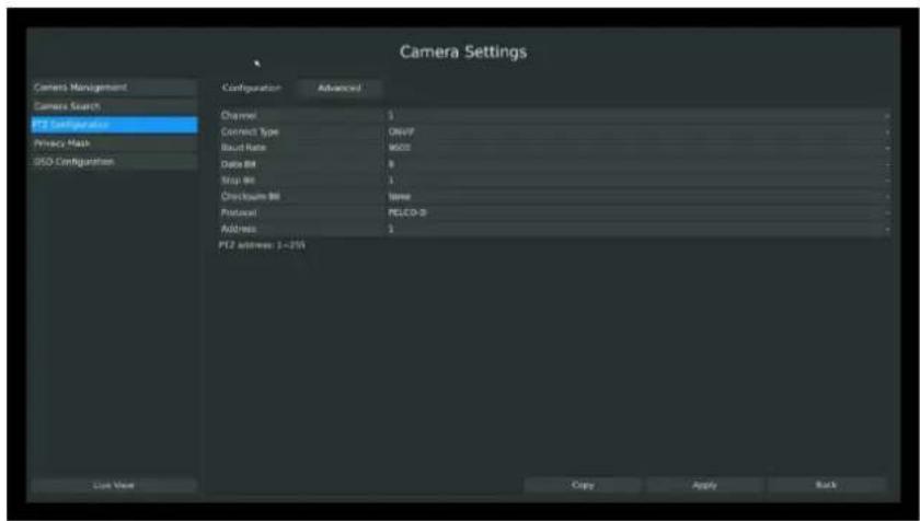
Enter configuration interface by clicking Main Menu → Camera → PTZ Configuration, select "Configuration" page. Choose a channel and set the PTZ parameters. Besides you can click [Copy] to copy the same configuration to other channels.
text_image
Camera Settings Camera Management Camera Search PTZ Configuration Privacy Mask OSO Configuration Configuration Advanced Channel 1 Connect Type 0.047 Baud Rate 9600 Data BM 8 Stop BM 1 Checkbox BM None Protocol PELCO-3 Address 1 PTZ address 1 - P55 List View Copy Apply RackF-3.3.19
Note:
-
Settings for a PTZ camera must be configured before it can be used. Make sure that the PTZ and RS-485 of the NVR are connected properly.
-
The PTZ protocol and address of IP channel must be consistent with those of the PTZ decoder.
3.3.3.2 Advanced Configuration
Main Menu → Camera → PTZ Configuration, select "Advanced" page. There are two patrol ways can be set: Track Patrol and Tour Patrol.
Note:
- IP channel does not support configuration and calling of presets, patrols and patterns.
- The functioning of presets patrols and patterns need front PTZ decoder to support.
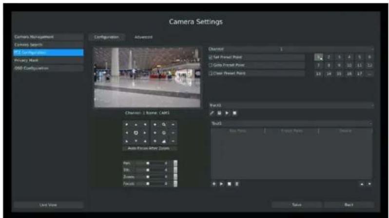
1. Presets Point Setup
Preset can be set to move your PTZ camera to a desired preset location. The preset point is the preparation for Tour Patrol.
Step1. Use the PTZ direction key to rotate the position of preset. Then select "Set Preset Point" and select a preset number to finish a preset point setting. Repeat above steps to set more preset points.
text_image
Camera Settings Camera Management Camera Search RT Configuration Privacy Map GSD Configuration Configuration Advanced Chrysler 1 Set Preset Point Go Into Preset Point Clear Preset Point Back1 Auto Focus After Zoom Zoom: Tilt: Zoom: Focus: Left View Save BackF-3.3.20
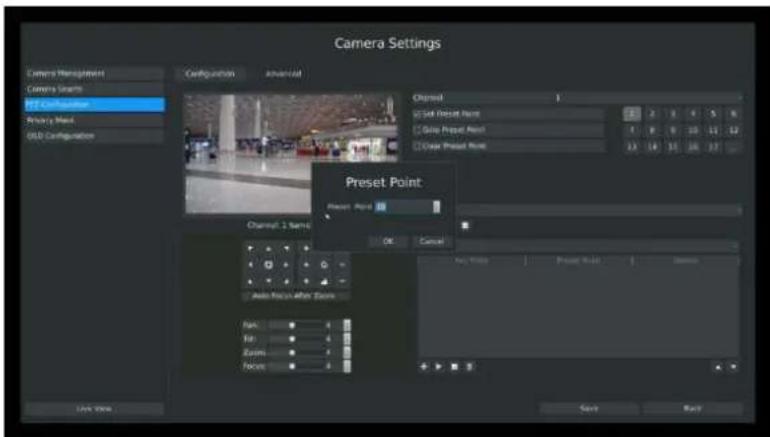
Step2. Click to save or call more preset points after number 17.
text_image
Camera Settings Camera Management Camera Search PTT Configuration Security Mask OLD Configuration Configuration Advanced Channel 1 Set Preset Point Grid Preset Point Grain Preset Point Grain Preset Point Preset Point OK Cancel Auto Focus After Zoom Max: Min: Zoom: Focus: Save BackF-3.3.21
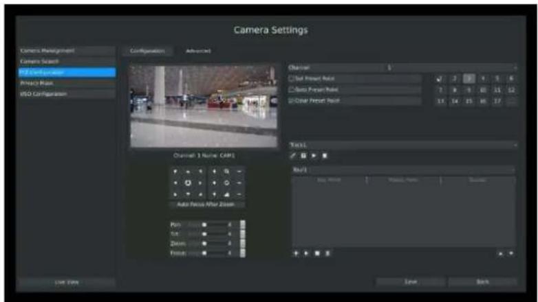
Step3. Select 'Clear Preset Point' and click a preset number to delete the preset point.
text_image
Camera Settings Camera Management Camera Scan PID Configuration Privacy Map MSO Configuration Configuration Advanced Channel 1 Name: CAMS Auto Focus After Zoom Pan: Top: Zoom: Front: Select View Select Select Select Select Select Select Select Select Select Select Select Select Select Select Select Select Select Select Select Select Select Select Select Select Select Select Select Select Select Select Select Select Select Select Select Select Select Select Select Select Select Select Select Select Select Select Select Select Select Select Auto Focus After ZoomF-3.3.22
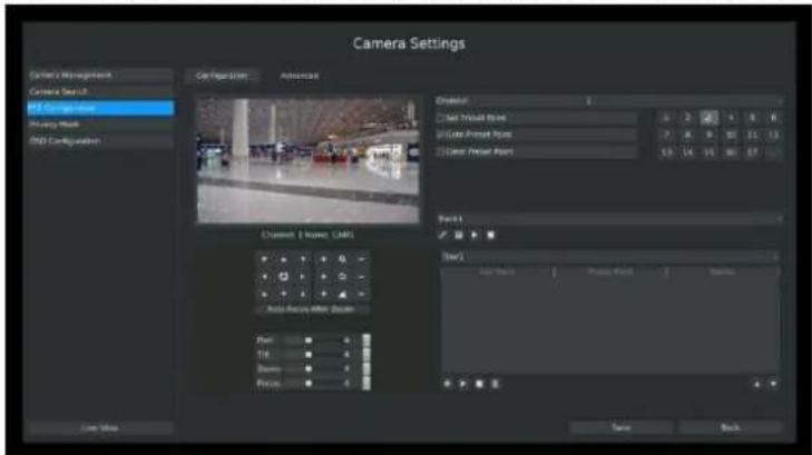
Step4. Select "Goto Preset Point". Click a preset number to check the preset point.
text_image
Camera Settings Camera Management Camera Set1 PT Compressor Binary Mask RGB Configuration Configuration Advanced Distal: Set Preset Point Set Preset Shift Set Preset Shift Auto Array After Zoom Play: Tik: Zoom: Pose: Back Top: 1 Bottom: 0 Top: 2 Bottom: 1 Top: 3 Bottom: 1 Bottom: 3 Top: 4 Bottom: 1 Bottom: 3 Top: 5 Bottom: 1 Bottom: 3 Top: 6 Bottom: 1 Bottom: 3 Top: 7 Bottom: 1 Bottom: 3 Top: 8 Bottom: 1 Bottom: 3 Top: 9 Bottom: 1 Bottom: 3 Top: 10 Bottom: 1 Bottom: 3 Top: 11 Bottom: 1 Bottom: 3 Top: 12 Bottom: 1 Bottom: 3 Top: 13 Bottom: 1 Bottom: 3 Top: 14 Bottom: 1 Bottom: 3 Top: 15 Bottom: 1 Bottom: 3 Top: 16 Bottom: 1 Bottom: 3 Top: 17 Bottom: 1 Bottom: 3 Top: 18 Bottom: 1 Bottom: 3 Top: 19 Bottom: 1 Bottom: 3 Top: 20 Bottom: 1 Bottom: 3 Top: 21 Bottom: 1 Bottom: 3 Top: 22 Bottom: 1 Bottom: 3 Top: 23 Bottom: 1 Bottom: 3 Top: 24 Bottom: 1 Bottom: 3 Top: 25 Bottom: 1 Bottom: 3 Top: 26 Bottom: 1 Bottom: 3 Top: 27 Bottom: 1 Bottom: 3 Top: 28 Bottom: 1 Bottom: 3 Top: 29 Bottom: 1 Bottom: 3 Top: 30 Bottom: 1 Bottom: 3 Top: 31 Bottom: 1 Bottom: 3 Top: 32 Bottom: 1 Bottom: 3 Top: 33 Bottom: 1 Bottom: 3 Top: 34 Bottom: 1 Bottom: 3 Top: 35 Bottom: 1 Bottom: 3 Top: 36 Bottom: 1 Bottom: 3 Top: 37 Bottom: 1 Bottom: 3 Top: 38 Bottom: 1 Bottom: 3 Top: 39 Bottom: 1 Bottom: 3 Top: 40 Bottom: 1 Bottom: 3F-3.3.23
2. Tour Patrol
The camera will patrol according to the key points. The total time and patrol speed of the tour is variable.
Step1. Select a tour. Up to 6 tours could be set.
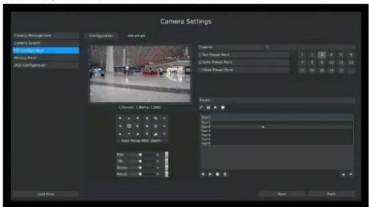
text_image
Camera Settings Camera Management Camera Brand 60 Camera Pair Wireg Plot 850 Configuration Advanced Camera Set Press Point Gett Press Point Clear Press Point Block1 Tier1 Tier2 Tier3 Tier4 Tier5 Tier6 Load Save Back Cancere 1. Mathen (CAM) Auto Pixel Pair Zoom Film: No: Zoom: Flake: Save BackF-3.3.24
Step2. Click to add key points. Set the key point parameters (including preset point number, scan time and scan speed) and click [OK].
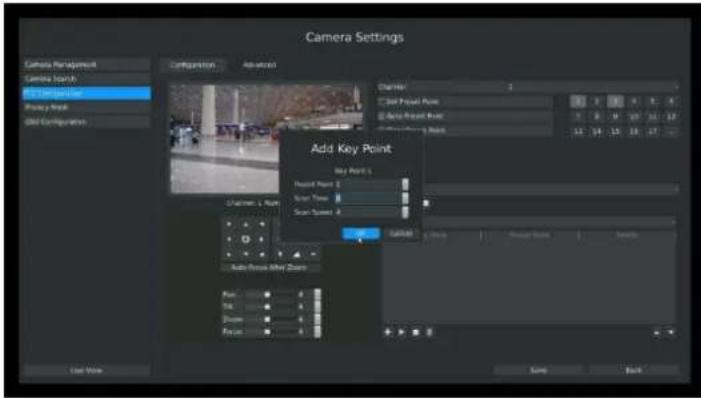
text_image
Camera Settings Camera Management Camera Search File Component Preview Array Gold Compositions Configuration Advanced Channel 1 Clear Project Point Clear Project Mask Add Key Point Key Point 1 Project Point 2 Sound Time 3 Sound Speed 4 Auto Focus After Zoom Play 5 View 6 Show 7 Focus 8 End View Save BackF-3.3.25
Step3. Repeat the above steps to add more key points to the tour patrol.
Step4. Select a key point, select [Delete] and select [Yes] in the dialog box to delete it.
Step5. Click to preview the tour patrol. Click to stop.
Step6. Click and select [Yes] in the dialog box to delete all key points of the tour patrol.
Note:
- The key point decides the patrol path, which will run according to numerical order of the key points.
- Scan time is how long the patrol stays on the preset point.
- Scan speed is the rotate speed of speed dome from one preset point to the next.
4. Track Patrol
The camera will patrol back and forth in a constant speed. There are only a start point and an end point.
Step1. Select a track and click . Up to 8 tracks could be set.
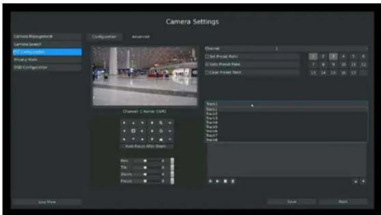
text_image
Camera Settings Driver Management Camera Search GT Compsafe Shading Mask USB Configuration Advanced Channel 1 Set Press Reset Get Preset Reset Get Preset Reset Track1 Track2 Track3 Track4 Track5 Track6 Track7 Track8 Auto Focus Min-Zoom Falls Trks Stairs Focus Save Now Save NextF-3.3.26
Step2. Drag the mouse or click 8 direction keys of mouse control field to rotate PTZ.
Step3. Click to save the PTZ movement patterns to the Track Patrol.
Step4. Click to preview the track patrol. Click to stop.
3.3.3.3 PTZ Control Operation
In live view mode, select quick menu of live view channel to enter PTZ control mode. It can access PTZ control by PTZ control bar or panel PTZ control button.
Description of PTZ Control Bar
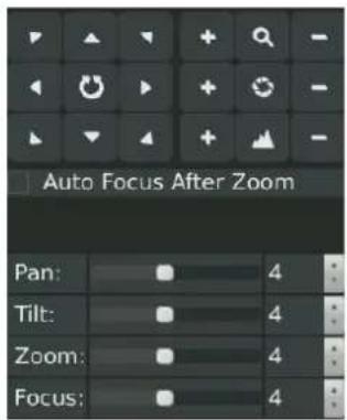
text_image
Auto Focus After Zoom Pan: 4 Tilt: 4 Zoom: 4 Focus: 4F-3.3.27
| Icon | Description | Icon | Description | Icon | Description |
 | PTZ Direction Control and Auto Scan Button |  | Adjust Zoom+, Focus+, IRIS+ |  | Adjust Zoom-,Focus-, IRIS- |
 | Zoom: Zoom in or out |  | Focus |  | IRIS |
 | Focus automatically after manual zoom | ||||
 | Horizontal Movement Adjustment | ||||
 | Vertical Movement Adjustment | ||||
 | Zoom Adjustment | ||||
 | Focus Adjustment | ||||
3.3.4 Privacy Mask
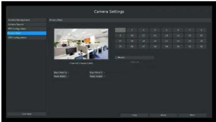
Milesight NVR support privacy mask. It used to cover some privacy area which is not proper to appear on monitor. Entering Privacy Mask interface by clicking: Main → Camera → Privacy Mask.
text_image
Camera Settings Camera Management Camera Search PT2 Configuration Entry Note ISO Configuration Proxy Main Channel 3 Number CAM View Point X : View Row X : View Height : View Alt : View Top : View Bottom : View Top (1) View Bottom (2) View Top (3) View Bottom (4) View Top (5) View Bottom (6) View Top (7) View Bottom (8) View Top (9) View Bottom (9) View Top (10) View Bottom (10) View Top (11) View Bottom (11) View Top (12) View Bottom (12) View Top (13) View Bottom (13) View Top (14) View Bottom (14) View Top (15) View Bottom (15) View Top (16) View Bottom (16) View Top (17) View Bottom (17) View Top (18) View Bottom (18) View Top (19) View Bottom (19) View Top (20) View Bottom (20) View Top (21) View Bottom (21) View Top (22) View Bottom (22) View Top (23) View Bottom (23) View Top (24) View Bottom (24) View Top (25) View Bottom (25) View Top (26) View Bottom (26) View Top (27) View Bottom (27) View Top (28) View Bottom (28) View Top (29) View Bottom (29) View Top (30) View Bottom (30) View Top (31) View Bottom (31) View Top (32) View Bottom (32) View Top (33) View Bottom (33) View Top (34) View Bottom (34) View Top (35) View Bottom (35) View Top (36) View Bottom (36) View Top (37) View Bottom (37) View Top (38) View Bottom (38) View Top (39) View Bottom (39) View Top (40) View Bottom (40) View Top (41) View Bottom (41) View Top (42) View Bottom (42) View Top (43) View Bottom (43) View Top (44) View Bottom (44) View Top (45) View Bottom (45) View Top (46) View Bottom (46) View Top (47) View Bottom (47) View Top (48) View Bottom (48) View Top (49) View Bottom (49) View Top (50) View Bottom (50) View Top (51) View Bottom (51) View Top (52) View Bottom (52) View Top (53) View Bottom (53) View Top (54) View Bottom (54) View Top (55) View Bottom (55) View Top (56) View Bottom (56) View Top (57) View Bottom (57) View Top (58) View Bottom (58) View Top (59) View Bottom (59) View Top (60) View Bottom (60) | Channel 3 Number CAM | Close at Start Point X : Start Row X : Start Height : Start Point Y : Start Row Y : Start Height : Start Point Z : Start Row Z : Start Height : Start Point X : Start Row X : Start Height : Start Point Y : Start Row Y : Start Height : Start Point Z : Start Row Z : Start Height : Start Point X : Start Row X : Start Height : Start Point Y : Start Row Y : Start Height : Start Point Z : Start Row Z : Start Height : Start Point X : Start Row X : Start Height : Start Row Y : Start Height : Start Point X : Start Row X : Start Height : Start Point Y : Start Row Y : Start Height : Start Point Z : Start Row Z : Start Height : Start Point X : Start Row X : Start Height : Start Point Y : Start Row Y : Start Height : Start Point Z : Start Row Z : Start Height : Start Point X : Start Row X :F-3.3.28
You can add a privacy mask by following steps:
Step1. Select channel on the right top of the interface, and enable it on the below of the channel;
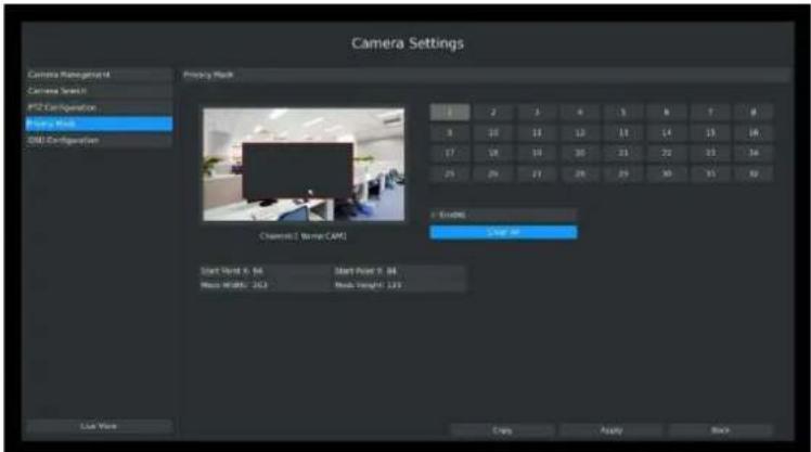
Step2. Set the area of privacy mask:
Way1: Drag the mouse to select the area which is privacy on the live window;
Way2: Set the coordinates of privacy area in the columns below the live window;
text_image
Camera Settings Camera Management Camera Scan1 PT2 Configuration Photo Mask CAM Configuration Projection Mask 1 2 3 4 5 6 7 8 8 10 11 12 13 14 15 16 17 18 19 20 21 22 23 24 25 26 27 28 29 30 31 32 F ENGL Channel E: Screen CAM Start Word X: 34 Start Point Y: 34 Mass WIDTH: 243 Load Length: 123 List View Copy Ready BackF-3.3.29
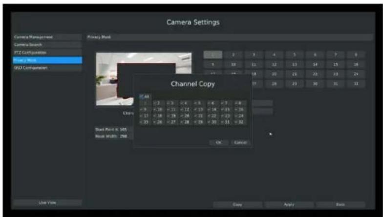
Step3. Copy the privacy area to the other channels by click the "copy" button on the bottom of the windows;
text_image
Camera Settings Camera Management Camera Search FTZ Configuration View 2 Work 0002 Configuration Proxy Mode Channel Copy View 2 Work View 1 Work Churn Stock Point: 6, 145 Week 1/2/01: 290 OK Cancel Use View Copy Apply BackF-3.3.30
Step4. Select "Apply" to save the settings.
3.3.5 OSD configuration
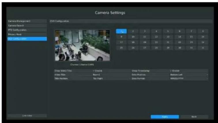
You can set OSD (On Screen Display) on NVR, and the OSD will be synchronized on IPC. Entering OSD Configuration interface by clicking: Main Menu→Camera→OSD Configuration.
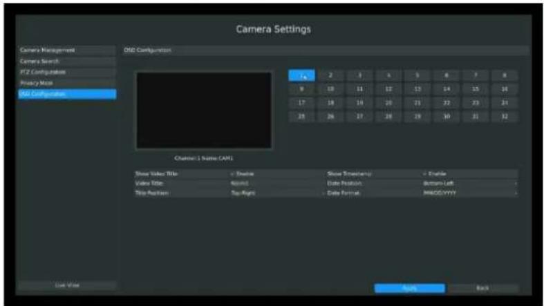
text_image
Camera Settings Camera Management Camera Search PTZ Configuration Privacy Mode CAM Configuration O&O Configuration Channel 1 Name CAM1 Show Video Title + Show Video Title 400/1 Show Streamings + Handle Title Position Tap Right Data Position Bottom Left Data Format BNOD/YYYY Play BackF-3.3.30
Step1. Select channel by clicking the channel number on the right-top, the selected channel will change into gray and the channel number will change into yellow;

Step2. Enable video title and timestamp:
| Show Video Title: | Enable | Show Timestamp: | Enable |
| Video Title: | Room1 | Date Position: | Bottom-Left |
| Title Position: | Top-Right | Date Format: | MM/DD/YYYY |
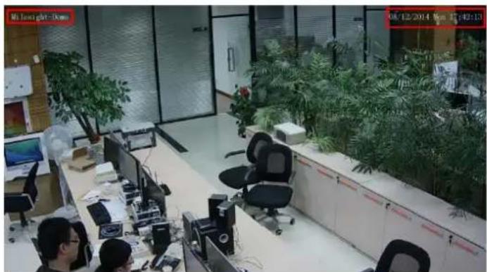
[Video Title]: Set the video title for the channel;
[Title Position]: Set the position for the video title: Top-Left or Top-Right;
[Date Position]: Set the position for the date: Top-Left, Top-Right, Bottom-Left or Bottom-Right;
[Date Format]: Set format for date: YYYY-MM-DD, MM/DD/YY or DD/MM/YYYY;
text_image
Camera Settings Camera Management Camera Search IPT2 Configuration Primary Mode OCT Configuration ISO Configuration Channel 1 (Name CAM) Show Video Title: 7 Options View Mode: Normal Edit View Name: New Image Show View Angle: 0° Show View Angle: 15° View Mode: Normal Edit View Name: Normal Output: Apply BackF-3.3.31
text_image
Mr Lower light-Down 08/12/2014 1pm 17:42:13F-3.3.32
Step3. Select "Apply" to save the settings.
3.4 Record Settings
Preparation for Configuration
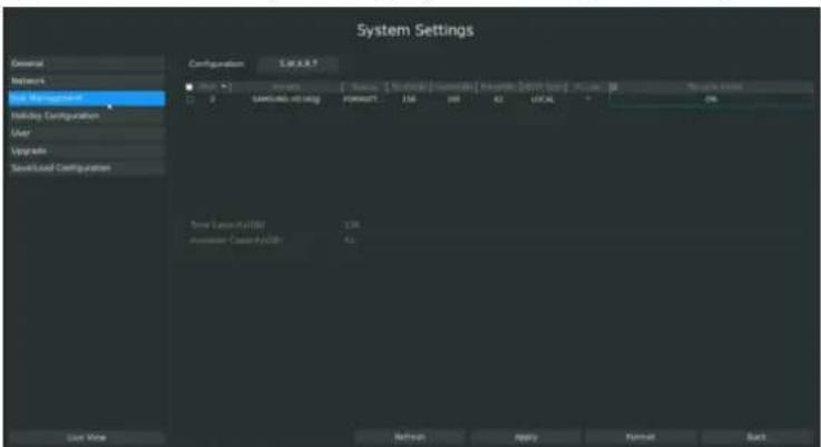
Step1. Ensure your NVR has Install and initialize the HDD.
Enter disk management interface by clicking System Setting Disk Management
text_image
System Settings General Network Job Management Building Configuration User Upgrade Save/Load Configuration Configuration S.R.R.R.T [ ] [ ] [ ] [ ] [ ] [ ] [ ] [ ] [ ] [ ] [ ] [ ] [ ] [ ] [ ] [ ] [ ] [ ] [ ] [ ] [ ] [ ] [ ] [ ] [ ] [ ] 0 1 2 3 4 5 6 7 8 9 10 11 12 13 14 15 16 17 18 19 20 21 22 23 24 25 26 27 28 29 30 31 32 33 34 35 36 37 38 39 40 41 42 43 44 45 46 47 48 49 50 51 52 53 54 55 56 57 58 59 60 61 62 63 64 65 66 67 68 69 70 71 72 73 74 75 76 77 78 79 80 81 82 83 84 85 86 87 88 89 90 91 92 93 94 95 96 97 98 99 100 Base Case(s): (100) (100) Inversion Case(s): (100) (100)F-3.4.1
Step2. Ensure that HDD has sufficient storage space.
Enter disk management interface by clicking System SettingDisk Management. Select [Recycle
Mode] to ON in the case of insufficient capacity of HDD.
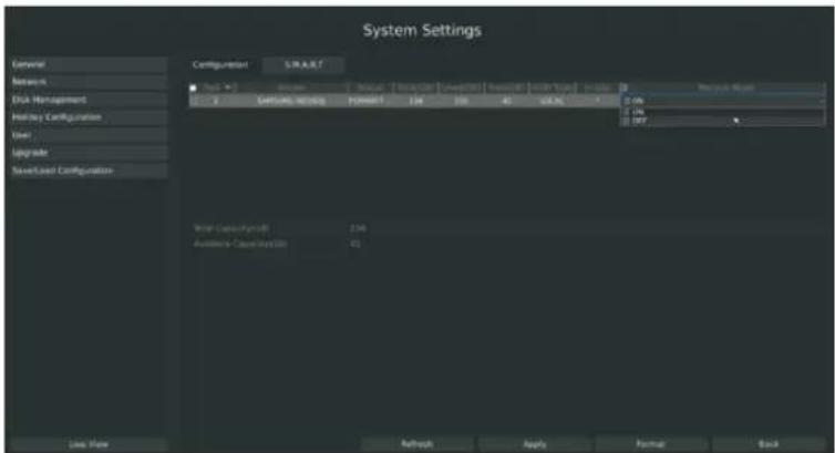
text_image
System Settings General Network Disk Management Holiday Configuration User Upgrade Save/Load Configuration Configuration: S.R.A.R.T Type: Normal Default Duration Length Width Width Value Size Maximal Mode X Offense Settings Habitat 134 108 40 6.2 M 0.0% ON OFF Total Capacity(GB) 134 Available Capacity(GB) 45 Live View Refresh Apply Format BackF-3.4.2
3.4.1 Record Mode
Step1. Enter record mode menu by clicking Main MenuRecord → Record Mode.
There are three record modes: No Recording/Always Record/Record by Schedule. You can select desired one to every channel.
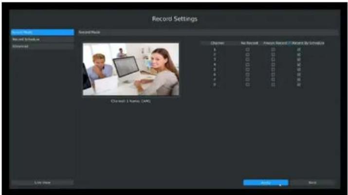
text_image
Record Settings Record Music Record Schedule Selected Second Music Channels: No Record Available Record Available by Schedule 1 2 3 4 5 6 7 8 9 10 11 12 13 14 15 16 17 18 19 20 21 22 23 24 25 26 27 28 29 30 31 32 33 34 35 36 37 38 39 40 41 42 43 44 45 46 47 48 49 50 51 52 53 54 55 56 57 58 59 60 61 62 63 64 65 66 67 68 69 70 71 72 73 74 75 76 77 78 79 80 81 82 83 84 85 86 87 88 89 90 91 92 93 94 95 96 97 98 99 Selected: No Record Available Record Available by Schedule List Store Next Add CancelF-3.4.3
[No Record]: NVR will not record if you choose this column;
[Always Record]: It will always record the chosen channel;
[Record By Schedule]: If you want NVR to record by schedule, then you need select this column and then go to 3.4.2;
Step2. Click [Apply] to save the configuration.
3.4.2 Record Schedule Setting
Note:
The days are divided as Holiday/Sunday/Monday/Tuesday/Wednesday/Thursday/Friday/Saturday. The schedule of Holiday is superior to other days. To set the holiday information, go to Chapter 3.8.4.
Method1. General Setting
Step1. Enter Record schedule interface by clicking Record Settings→Record Schedule
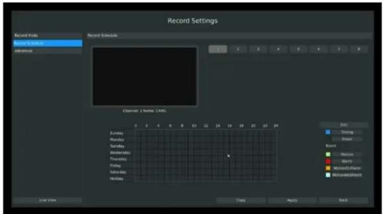
text_image
Record Settings Record Mode Record Schedule Record Schedule Channel 1 Name: CAML Sunday Monday Tuesday Wednesday Thursday Friday Saturday Holiday 0 2 4 6 8 10 12 14 16 18 20 22 24 Sun Timing Event Event Balance Balance Maximum Balance Minimum Maximum Live View Copy Apply BackF-3.4.4
Step2. Select desired channel (e.g. Channel 1) and click [Edit] button
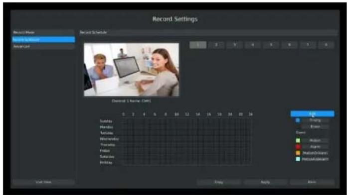
text_image
Record Settings Record Name: Record Schedule: Channel 1 Name: CMCL Sunday Monday Tuesday Wednesday Thursday Friday Saturday Holiday OK Preview Reset Event Action Again MotionOrigin Photoableam Exit Value Apply Apply BlockF-3.4.5
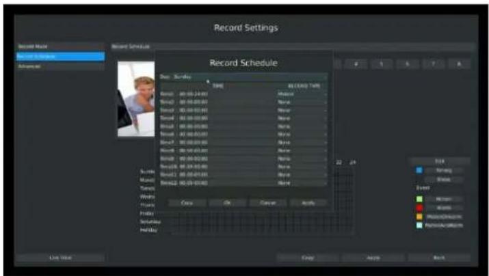
Step3. Set record schedule
Select a day from the drop-down list of [Day], and select [Record Type] to setup the recording period, up to 12 periods can be set. (e.g.01:00 to 05:00 for none recording; 06:00 to 18:00 for timing recording; 19:00 to 21:00 for Motion recording; 22:00 to 24:00 for Alarm recording)
text_image
Record Settings Record Music Record & Record Advanced Record Schedule Record Schedule Track Trunk Music Radio Radio/Drama Radio/Drama Audio Audio Audio Audio Audio Audio Audio Audio Audio Audio Audio Audio Audio Audio Audio Audio Audio Audio Audio Audio Audio Audio Audio Audio Audio Audio Audio Audio Audio Audio Audio Audio Audio Audio Audio Audio Audio Audio Audio Audio Audio Audio Audio Audio Audio Audio Audio Audio Audio Audio 12.24% STK Narang Blosses Event Mitarin Ricardo Radio/Drama Radio/DramaF-3.4.6
Note:
Time periods cannot overlap with each other.
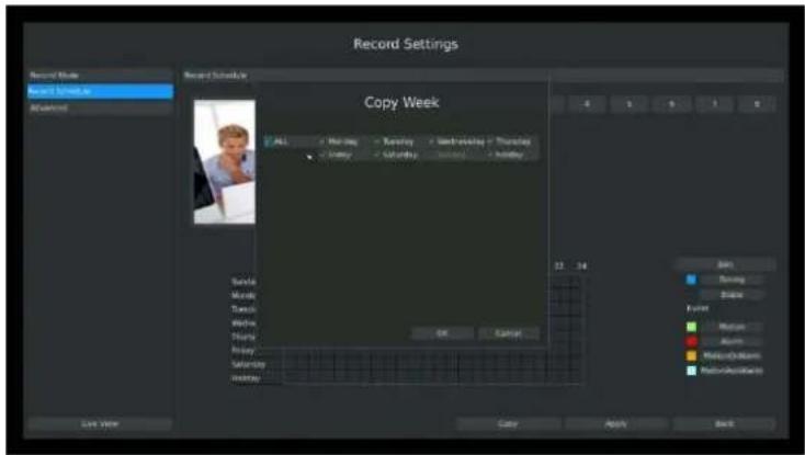
Step4. Click [Copy] to copy settings to other weekdays, and then click [Apply] to confirm the
setting.
text_image
Record Settings Record Style Record Schedule Record Time Record Schedule Copy Week ALL Monday Tuesday Wednesday Thursday Friday Saturday Sunday Thursday OK Cancel 23 24 Box Swing Shape Event Macau Acruv Macquity-Storm Maculose-Storm Save View Cancel Apply BackF-3.4.7
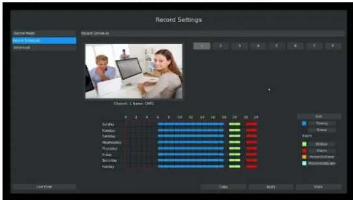
Step5. After above steps, this channel with show as below:
text_image
Record Settings Record Mode Record Simple Advanced Record Settings Channel 1 Name: CAF1 Saturn Tuning Boxing Export Window Face Rebeefishers Motorizedcam Live Time Copy Apply StartsF-3.4.8
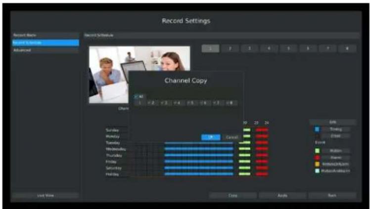
Step6. Copy the recording settings to other channels
Select [Copy] to copy the same settings to other channels. And click [OK] to save the configuration.
text_image
Record Settings Record Back Record Schedule Advanced Recent Schedule Channel Copy All Share Sunday Monday Tuesday Wednesday Thursday Friday Saturday Friday 10 20 24 Cancel 80 70 60 50 40 30 20 10 8 6 5 4 3 2 1 0 9 8 7 6 5 4 3 2 1 0 9 8 7 6 5 4 3 2 1 0 9 8 7 6 5 4 3 2 1 0 9 8 7 6 5 4 3 2 1 0 9 8 7 6 5 4 3 2 1 0 9 8 6 5 4 3 2 1 0 9 8 7 6 5 4 3 2 1 0 9 8 7 6 5 4 3 2 1 0 9 8 7 6 5 4 3 2 1 0 9F-3.4.9
Step7. Save the configuration
Click [Apply] button to save the configuration, and then click [Back] to return to the previous menu.
Method2.Set record schedule by drag the mouse
Step1. Enter Record schedule interface by clicking Record Settings→Record Schedule
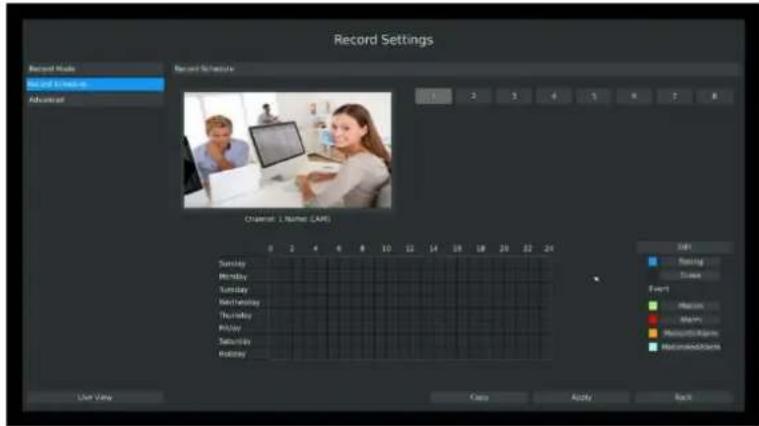
text_image
Record Settings Record Mode Record Settings Advanced Record Schedule Channel: 1, Number: (LARE) 0 2 4 6 8 10 12 14 16 18 20 22 24 Sunday Monday Tuesday Wednesday Thursday Friday Saturday Holiday 10/1 Racing Clear Event Motion Sharp Multipliers Multipliers Live View Case Apply BackF-3.4.10
Step2. Click desired channel and record type show as below:
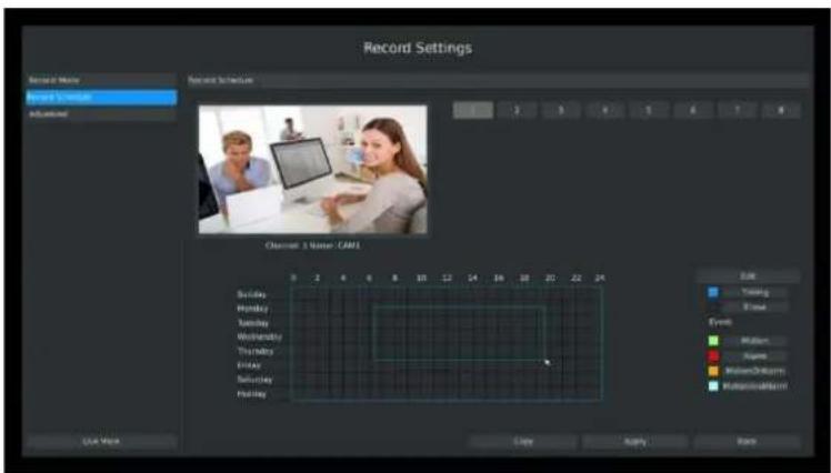
text_image
Record Settings Record Name Record Sequence Record Interval Channel 1 Name: CAMI Schedule Monday Tuesday Wednesday Thursday Friday Saturday Sunday Friday 5 2 4 6 8 10 12 14 16 18 20 22 24 Color Yesting Time Eyes Mitarin Apsin WatanOrkum RutationalInvent Use Work Clay Apply RunF-3.4.11
Step3. Drag the mouse to draw certain areas in recording setting zone and then click[Apply] to save the configuration.
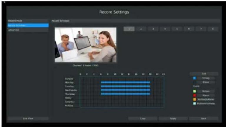
text_image
Record Settings Record Mode Record Schedule Advanced Record Schedule 1 2 3 4 5 6 7 8 Channel: 1 Name: C:\AG Sunday Monday Tuesday Wednesday Thursday Friday Saturday Holiday End Strong Black Event Windows Alarm Microsoft\MyBlock Microsoft\MyBlock Live Your Copy Reply BackF-3.4.12
Step4. Copy the recording settings to other channels.
Select [Copy] to copy the same settings to other channels. And click [OK] to save the configuration.
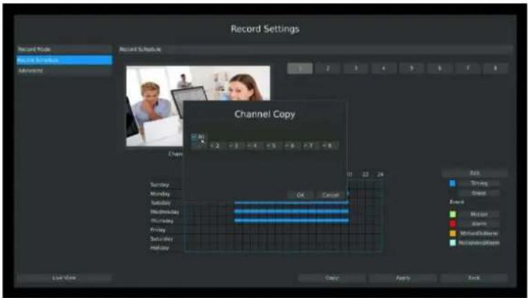
text_image
Record Settings Record Mode Recording Scope Advanced Record Schedule 1 2 3 4 5 6 7 8 Channel Copy OK Cancel Sunday Monday Tuesday Wednesday Thursday Friday Saturday Sunday Holiday Run Timing Change Event Mission Alarm Midland/Disaster Recapac#dcrism Use Now Copy Apply BackF-3.4.13
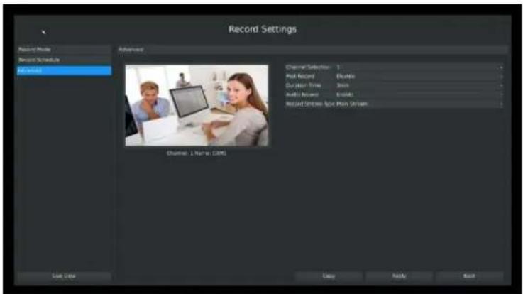
3.4.3 Advanced settings
You can set the advanced settings there.
text_image
Record Settings Record Mode Record Schedule Off Record Advanced Channel Selection: 1 Post Record Duration Time Audio Record Record Stream Type: Main Stream Channel 1 Name: CAML List Use Entry Reply BackF-3.4.14
Illustration for Parameters
[Channel Selection]: Select the channel which will be set.
[Post Record]: Enable/Disable post record after the event is over
[Duration Time]: Event pre-record duration before event alarm
[Audio Record]: Select to record audio or not
[Record Stream Type]: Select Main stream or sub stream for record
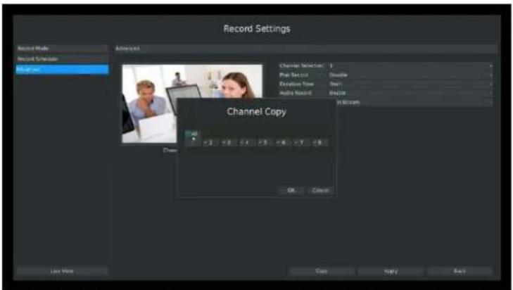
Lastly choose you can choose the copy button to copy the settings of record for other channels.
text_image
Record Settings Record Mode Record Simulator Background Channel Copy Channel Selection: Plain Ret and Double Duration Time: 10% Audio Record: Double In Minahs OK Cancel Last View Copy Reply BackF-3.4.15
3.5 Event Settings
3.5.1 Video Loss
Your NVR can be setup to detect video loss and trigger an action.
Step1. Enter video loss configuration interface by clicking Main Menu→Event→Video Loss.

text_image
Event Settings Video Lines Movie Selection Action Input Event Output Dimensions Video Lines Channel 1 Name (CAM) Action 20 fps Live Video Copy Apply BackF-3.5.1
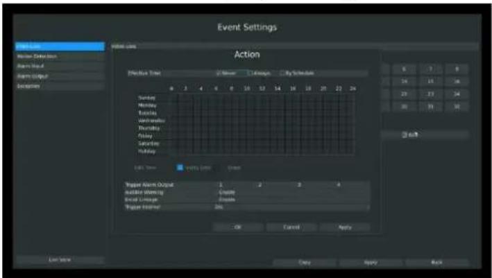
Step2. Select a desired channel and click [Edit] to configure video loss.
text_image
Event Settings Action Event Data Type: 100 MHz 1 GHz 24 GHz By Schedule Sunday Monday Tuesday Wednesday Thursday Friday Saturday Sunday EBS Term Trigger Alert Limit Green Trigger Alert Output Nuclear Eventing Serial Image Trigger Sounder 1 2 3 4 OK Cancel Apply Save Now Copy Apply BackF-3.5.2
Step3. Select effective time to setup when you want to trigger actions once video loss is
detected.

text_image
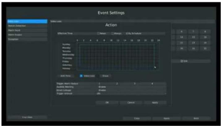
Effective Time ✓ Never □ Always □ By Schedule[Never]: Your NVR will not trigger any actions when [Never] button is checked. No matter the [Audible Warning] or [Email Linkage] check-boxes are checked or not.
[Always]: Your NVR will always trigger actions when [Always] button is checked. Please make sure [Audible Warning] or [Email Linkage] is checked.
[By Schedule]: You can drag the mouse to draw certain area in schedule setting zone, show as below:
text_image
Event Settings Action Effective Time Balance Balance By Schedule Sunday Monday Tuesday Wednesday Thursday Friday Saturday Sunday Finish Back Time Visible Time Drawn Trigger: Alarm Direction 4 2 3 4 Audio: Memory 8 minutes Street: Calendar 6 minutes Trigger: Eventset OK Cancel Apply End Options Apply Apply NextF-3.5.3
After dragging this will show as below:
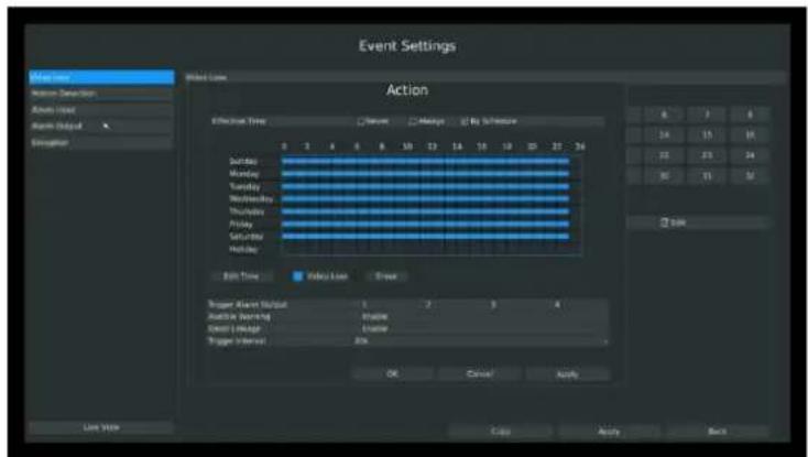
text_image
Event Settings Action Effect Time Duration Message By Software Sunday Monday Tuesday Wednesday Thursday Friday Saturday Holiday Edit Time Delay Line Break Trigger Alert Output 1 2 3 4 Accessible Warning Accessible Created Message Created Trigger Interest 2% OK Cancel Apply Back Line View Copy Apply BackF-3.5.4
Or click [Edit Time] to set schedules. Schedule can be set for all week or any day of the week with up to 12 time periods per day. Video loss actions take effect in the scheduled period only.
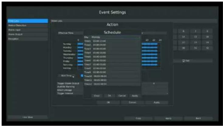
text_image
Event Settings Show Link Show Link Action Schedule Show Time 0 Sunday Monday Time1 00:00-23:00 Time2 00:00-25:00 Time3 00:00-27:00 Time4 00:00-29:00 Time5 00:00-31:00 Time6 00:00-33:00 Time7 00:00-35:00 Time8 00:00-37:00 Time9 00:00-39:00 Time10 00:00-41:00 Time11 00:00-43:00 Time12 00:00-45:00 Copy OK Cancel Apply OK Cancel Apply Add Now Add Now Add Now Add Now Add Now Add Now Add Now Add Now Add Now Add Now Add Now Add Now Add Now Add Now Add Now Add Now Add Now Add Now Add Now Add Now Add Now Add Now Add Now Add Now Add Now Add Now Add Now Add Now Add Now Add Now Add Now Add Now Add Now Add NowF-3.5.5
Note:
Time periods cannot overlap with each other.
Step4. Click [Copy] to copy the video loss schedule to other weeks, and then click [OK].
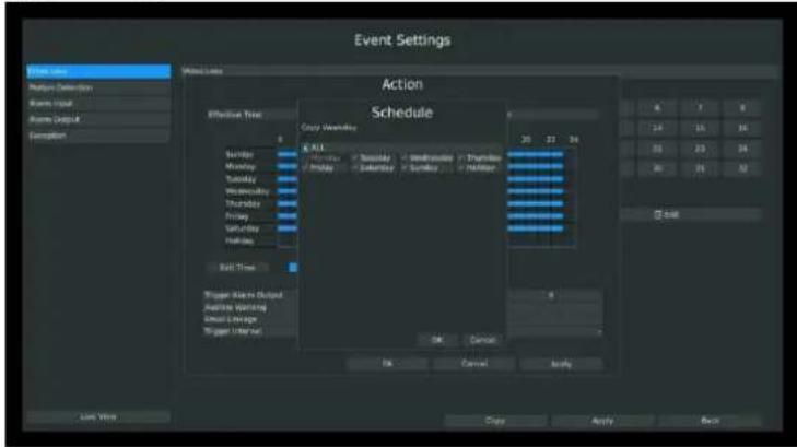
text_image
Event Settings Action Schedule Effortive Tree K-ALL Sunday - Saturday - Wednesday - Thursday Friday - Saturday - Sunday - Friday 8:30 23:34 OK Cancel OK Cancel Apply Live Now Copy Apply BackF-3.5.6
Step5. Select actions you want when video loss is detected.
| Trigger Alarm Output | 1 | 2 | 3 | 4 |
| Audible Warning | Enable | |||
| Email Linkage | Enable | |||
| Trigger Interval | 20s | |||
[Trigger Alarm Output]: Select whether trigger the alarm output or not when video loss is detected.
[Audible Warning]: Trigger an audible beep when video loss is detected
[Email Linkage]: Send video loss note to specified email address when video loss is detected. (Please refer to 3.8.2.4 Mail configuration for mail address setting)
[Trigger Interval]: Set the interval between two events.
Note:
These actions will only take response according to effective time you choose
Step6. Click [OK] or [Apply] to confirm the settings. Repeat above steps for other channels. Or click [Copy] to copy settings to other channels.
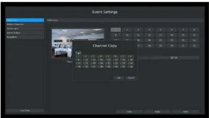
text_image
Event Settings Channel Copy OK Cancel Copy Apply BackF-3.5.7
3.5.2 Motion Detection
Your NVR can be setup to motion detect and trigger an action. You can set the motion detection on NVR or on IPC web, both sides' settings will be synchronous in both devices.
Step1. Enter motion detection setting interface by clicking Main Menu → Event → Motion Detection.
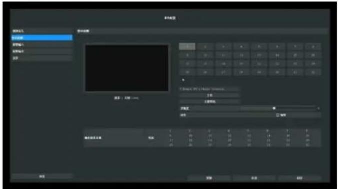
text_image
文件(F) 编辑(E) 视图(V) 插入(I) 格式(O) 帮助(H) 新建(N) 删除(D) 重命名(M) 粘贴(P) 复制(C) 粘贴(P)... Ctrl+Alt+Alt+Alt+Alt+Alt+Alt+Alt+Alt+Alt+Alt+Alt+Alt+Alt+Alt+Alt+Alt+Alt+Alt+Alt+Alt+Alt+Alt+Alt+Alt+Alt+Alt+Alt+Alt+Alt+Alt+Alt+Alt+Alt+Alt+Alt+Alt+Alt+Alt+Alt+Alt+Alt+Alt+Alt+Alt+Alt+Alt+Alt+Alt+Alt+Alt+ Alt+F 文件(F) 编辑(E) 视图(V) 插入(I) 格式(O) 粘贴(P) 复制(C) 粘贴(P) Ctrl+Alt+Alt+Alt+Alt+Alt+Alt+Alt+Alt+Alt+Alt+Alt+Alt+Alt+Alt+Alt+Alt+Alt+Alt+Alt+Alt+Alt+Alt+Alt+Alt+Alt+Alt+Alt+Alt+Alt+ Alt+F 确定 取消 应用 帮助F-3.5.8
Step2. Set the trigger area for motion detection.
You can set the area by dragging the mouse on live view window:
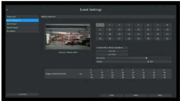
text_image
Event Settings Main view Event Detection Main input Main output Exceptions Channels & Media (CAM) Photo ID: 2016-03-01 Project Channels Record Add: 1 Add: 2 Add: 3 Add: 4 Add: 5 Add: 6 Add: 7 Add: 8 Add: 9 Add: 10 Add: 11 Add: 12 Add: 13 Add: 14 Add: 15 Add: 16 Add: 17 Add: 18 Add: 19 Add: 20 Add: 21 Add: 22 Add: 23 Add: 24 Add: 25 Add: 26 Add: 27 Add: 28 Add: 29 Add: 30 Add: 31 Add: 32 Add: 33 Add: 34 Add: 35 Add: 36 Add: 37 Add: 38 Add: 39 Add: 40 Add: 41 Add: 42 Add: 43 Add: 44 Add: 45 Add: 46 Add: 47 Add: 48 Add: 49 Add: 50 Add: 51 Add: 52 Add: 53 Add: 54 Add: 55 Add: 56 Add: 57 Add: 58 Add: 59 Add: 60 Add: 61 Add: 62 Add: 63 Add: 64 Add: 65 Add: 66 Add: 67 Add: 68 Add: 69 Add: 70 Add: 71 Add: 72 Add: 73 Add: 74 Add: 75 Add: 76 Add: 77 Add: 78 Add: 79 Add: 80 Add: 81 Add: 82 Add: 83 Add: 84 Add: 85 Add: 86 Add: 87 Add: 88 Add: 89 Add: 90 Add: 91 Add: 92 Add: 93 Add: 94 Add: 95 Add: 96 Add: 97 Add: 98 Add: 99 Add: 100F-3.5.9
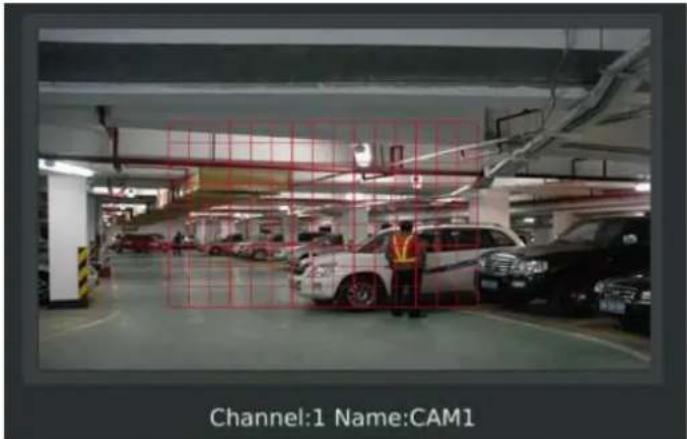
text_image
Channel:1 Name:CAM1F-3.5.10
And meanwhile the area will be synchronized in IPC.
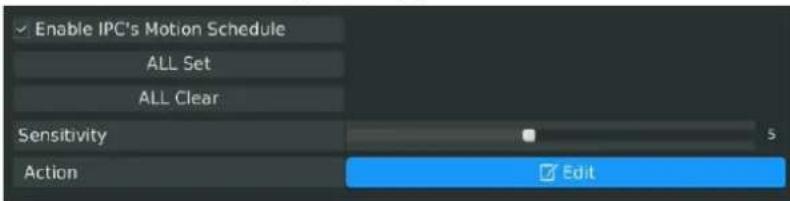
Step3. Select the schedule, sensitivity and trigger area for motion detection.
text_image
Enable IPC's Motion Schedule ALL Set ALL Clear Sensitivity 5 Action Edit[Enable IPC's Motion]: If it is enabled here, motion detect will take effect 7*24h; If it is not enabled, motion detect will take effect as the schedule which is set on the camera web.
[All Set]: Set all area as the trigger area;
[All Clear]: Clear all trigger area;
[Sensitivity]: Set sensitivity for motion detection, range from 1 to 10. It will synchronize to IPC if you set sensitivity here;
[Action]: Edit action once motion is detected, refers to next step;
Step4. Select the desired channel and click [Edit] to configure motion detection action.

text_image
Action Event Settings Action Effective Time Never Always By Eventset Sunday Friday Tuesday Wednesday Thursday Friday Saturday Sunday Friday 2013 Peak Multiple Current Regular Alarm Output 5 2 7 4 Normal Warning Monday 14 15 16 Event Linkage Tuesday 22 23 24 Regular Manual 3% OK Cancel Apply Edit Save Time Color Apply BackF-3.5.11
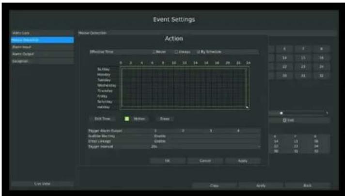
Step5. Select effective time to setup when you want to trigger actions once motion is detected.

text_image
Effective Time ✓ Never □ Always □ By Schedule[Never]: Your NVR will not trigger any actions when [Never] button is checked. No matter the [Audible Warning] or [Email Linkage] check-boxes are checked or not.
[Always]: Your NVR will always trigger actions when [Always] button is checked. Please make sure [Audible Warning] or [Email Linkage] is checked.
[By Schedule]: You can drag the mouse to draw certain area in schedule setting zone, show as below:
text_image
Event Settings Action Effective Time Never Always By Schedule 8 3 4 5 6 7 8 9 10 11 12 13 14 15 16 17 18 19 20 21 22 23 Sunday Monday Tuesday Wednesday Thursday Friday Saturday Sunday Friday Exit Time Motion Show Tigger Event Output Start Time Start Time Start Time Start Time Start Time Start Time Start Time Start Time Start Time Start Time Start Time Start Time Start Time Start Time Start Time Start Time Start Time Start Time Start Time Start Time Start Time Start Time Start Time Start Time Start Time Start Time Start Time Start Time Start Time Start Time Start Time Start Time Start Time Start TimeF-3.5.12
After dragging, this channel will show as below:
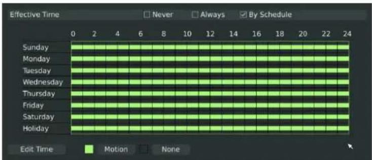
text_image
Effective Time 0 2 4 6 8 10 12 14 16 18 20 22 24 Sunday Monday Tuesday Wednesday Thursday Friday Saturday Holiday Never Always By Schedule Edit Time Motion NoneF-3.5.13
Or click [Edit Time] to setup schedules. Schedule can be set for all week or any day of the week with up to 12 time periods per day. Motion detection actions take effect in the scheduled period only.
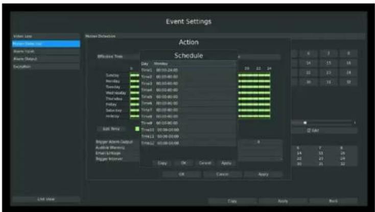
text_image
Event Settings Action Schedule Efficient Time Daily Monday Sunday 00:00:24:00 Sunday 00:00:00:00 Sunday 00:00:00:00 Sunday 00:00:00:00 Sunday 00:00:00:00 Sunday 00:00:00:00 Sunday 00:00:00:00 Sunday 00:00:00:00 Sunday 00:00:00:15 Sunday 00:00:00:15 Sunday 00:00:15 Sunday 00:15 Sunday 15 Sunday 25 Sunday 35 Sunday 45 Sunday 55 Sunday 65 Sunday 75 Sunday 85 Sunday 95 Sunday 105 Sunday 115 Sunday 125 Sunday 135 Sunday 145 Sunday 155 Sunday 165 Sunday 175 Sunday 185 Sunday 195 Sunday 205 Sunday 215 Sunday 225 Sunday 235 Sunday 245 Sunday 255 Sunday 265 Sunday 275 Sunday 285 Sunday 295 Sunday 305 Sunday 315 Sunday 325 Sunday 335 Sunday 345 Sunday 355 Sunday 365 Sunday 375 Sunday 385 Sunday 395 Sunday 405 Sunday 415 Sunday 425 Sunday 435 Sunday 445 Sunday 455 Sunday 465 Sunday 475 Sunday 485 Sunday 495 Sunday 505 Sunday 515 Sunday 525 Sunday 535 Sunday 545 Sunday 555 Sunday 565 Sunday 575 Sunday 585 Sunday 595 Sunday 605 Sunday 615 Sunday 625 Sunday 635 Sunday 645 Sunday 655 Sunday 665 Sunday 675 Sunday 685 Sunday 695 Sunday 705 Sunday 715 Sunday 725 Sunday 735 Sunday 745 Sunday 755 Sunday 765 Sunday 775 Sunday 785 Sunday 795 Sunday 805 Sunday 815 Sunday 825 Sunday 835 Sunday 845 Sunday 855 Sunday 865 Sunday 875 Sunday 885 Sunday 895 Sunday 905 Sunday 915 Sunday 925 Sunday 935 Sunday 945 Sunday 955 Sunday 965 Sunday 975 Sunday 985 Sunday 995 Sunday 100F-3.5.14
Note:
Time period cannot overlay with each other
Step6. Click [Copy] to copy the motion detection schedules to other weekdays.
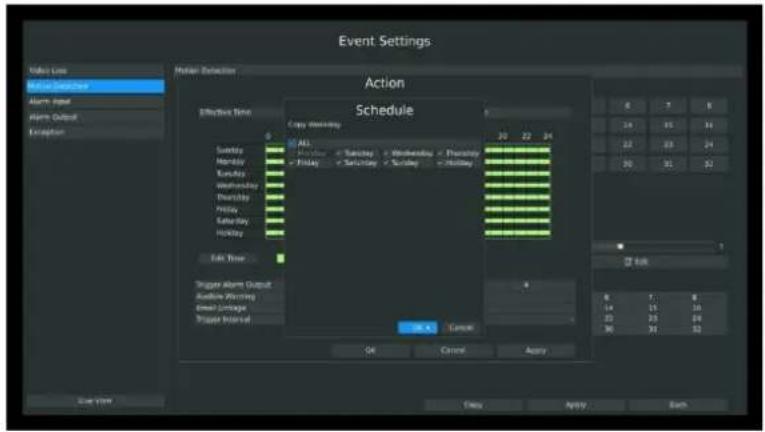
text_image
Event Settings Video Loss Movie Showcase Alarm Input Alert Output Exception Motion Detector Action Schedule Effective Time Copy birthday 30 22 24 Sunday Monday Friday Saturday Wednesday Thursday Friday Saturday Holiday Edit User Trigger Alarm Output Audience Warning Event Linkage Trigger Interval OK Cancel Apply OK Cancel Apply Each 8 7 6 19 15 14 22 23 24 30 31 32 EVR 8 7 6 14 15 16 22 23 24 30 31 32F-3.5.15
Step7. Select actions you want when motion is detected
| Trigger Alarm Output | 1 | 2 | 3 | 4 |
| Audible Warning | Enable | |||
| Email Linkage | Enable | |||
| Trigger Interval | 20s | |||
[Trigger Alarm Output]: Select whether trigger the alarm output or not when video loss is detected.
[Audible Warning]: Trigger an audible beep when video loss is detected
[Email Linkage]: Send video loss note to specified email address when video loss is detected.(Please refer to 3.8.2.4 Mail configuration for mail address setting)
[Trigger Interval]: Set the interval between two events.
Note:
These actions will only take response according to effective time you choose.
Step8. [Trigger Channels Record]: Select channels to trigger for recording when motion is detected by checking the check-boxes under the desired channels. Please make sure other channels has setup motion recording schedule. (Refer to 3.4 Record settings)
| Trigger Channels Record | ALL | 1 | 2 | 3 | 4 | 5 | 6 | 7 | 8 |
| 9 | 10 | 11 | 12 | 13 | 14 | 15 | 16 | ||
| 17 | 18 | 19 | 20 | 21 | 22 | 23 | 24 | ||
| 25 | 26 | 27 | 28 | 29 | 30 | 31 | 32 |
Step9. Click [Apply] or [OK] to confirm settings. Repeat above steps to other channel. Or click [Copy] to copy settings to other channel.
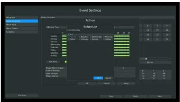
text_image
Event Settings Action Schedule OK Cancel Apply Time Line Energy Consumption Alarm Event Alarm Output Examples Motion Detection Effective Time Sunday Monday Tuesday Wednesday Thursday Friday Saturday Sunday Friday Saturday Sunday Friday Take Time Beginer Alarm Signal Audience Warning Email Linker Beginer Interact 8 7 6 24 25 26 23 24 25 10 11 12 OK Cancel Apply Clear Apply BackF-3.5.16
3.5.3 Alarm Input
Alarm Input function is supported in some specific models. Please make sure your NVR has such function first.
Step1. Select Main Menu-Event-Alarm Input.
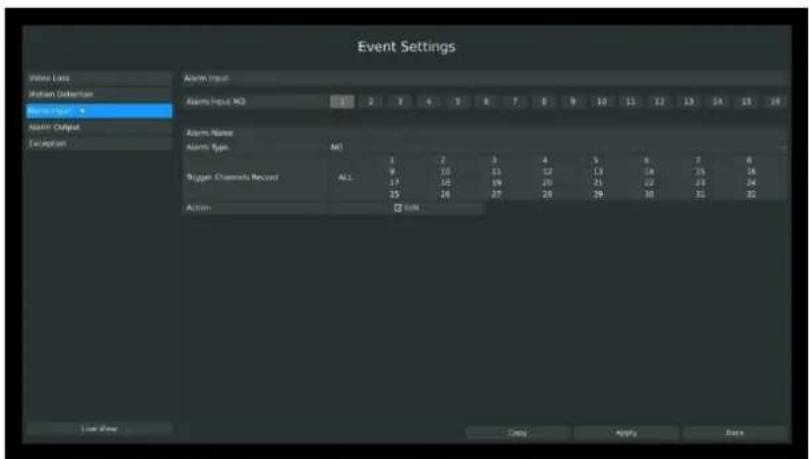
text_image
Event Settings Video Loss Motion Detection Reverance Alarm Output Exception Alarm Input Alarm Input NO 1 2 3 4 5 6 7 8 9 10 11 12 13 14 15 16 Alarm Name Alarm Type: M1 9 10 11 12 13 14 15 16 Bigger Channels Record ALL 17 18 19 20 21 22 23 24 Action: ☑ Edit Copy Apply BackF-3.5.17
Step2. Set Alarm input channel, Alarm Name, Alarm Type and Record Channels.
| Alarm Input NO. | 1 | 2 | 3 | 4 | 5 | 6 | 7 | 8 | 9 | 10 | 11 | 12 | 13 | 14 | 15 | 16 |
| Alarm Name | ||||||||||||||||
| Alarm Type | NO | |||||||||||||||
| 1 | 2 | 3 | 4 | 5 | 6 | 7 | 8 | |||||||||
| Trigger Channels Record | ALL | 9 | 10 | 11 | 12 | 13 | 14 | 15 | 16 | |||||||
| 17 | 18 | 19 | 20 | 21 | 22 | 23 | 24 | |||||||||
| 25 | 26 | 27 | 28 | 29 | 30 | 31 | 32 | |||||||||
| Action | ||||||||||||||||
F-3.5.18
[Alarm Input NO]: The channel which has input signal;
[Alarm Name]: Set a name for the alarm;
[Alarm Type]: Select alarm type: NO or NC;
[Trigger Channels Record]: Once the channel in the [Alarm Input No] has alarm input, which channels will be triggered to record. Refer to 3.4 Record Settings;
Step3. Set action for alarm input.
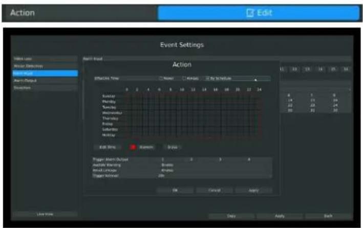
text_image
Action Event Settings Start Menu Show Event Settings Event Manager Event Address Evolution Event Head Action Effective View Name Events By to Nexture 0 2 4 6 8 10 12 14 16 18 20 22 24 Sunday Monday Tuesday Wednesday Thursday Friday Saturday Sunday Editor Time System Brays Trigger Alert Event 1 2 3 4 Accessible Eventing 5 minutes Initial Eventor 40 minutes Trigger Alerted 20s OK Cancel Apply Save Now Date Apply BackF-3.5.19
You need to set 1.Effective time and 2.Action on this Action Interface:
1. Effective time:
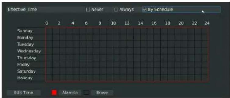
text_image
Effective Time Never Always By Schedule Sunday Monday Tuesday Wednesday Thursday Friday Saturday Holiday Edit Time Alarmin EraseF-3.5.20
You can set three different modes for effective time:
[Never]: Will have no action triggered if it is checked;
[Always]: Will always trigger the action if checked;
[By Schedule]: Will take effect by the schedule you set.
If you choose By Schedule, you need to set schedule by 1.drag the mouse on the time schedule area or 2.by click the "Edit Time" button.
2. Action
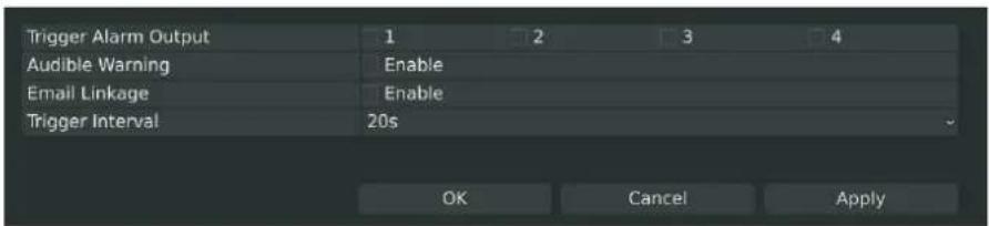
text_image
Trigger Alarm Output 1 2 3 4 Audible Warning Enable Email Linkage Enable Trigger Interval 20s OK Cancel ApplyF-3.5.21
[Trigger Alarm Output]: Select whether trigger the alarm output or not when video loss is detected.
[Audible Warning]: Trigger an audible beep when video loss is detected
[Email Linkage]: Send video loss note to specified email address when video loss is detected. (Please refer to 3.8.2.4 Mail configuration for mail address setting)
[Trigger Interval]: Set the interval between two events.
Note:
These actions will only take response according to effective time you choose.
Lastly need to APPLY these settings to take effect.
3.5.4 Alarm Output
Alarm Output function is supported on MS-N5016, MS-N5116, MS-N8016, MS-N8032.
Step 1. Select Main Menu-Event-Alarm Output:
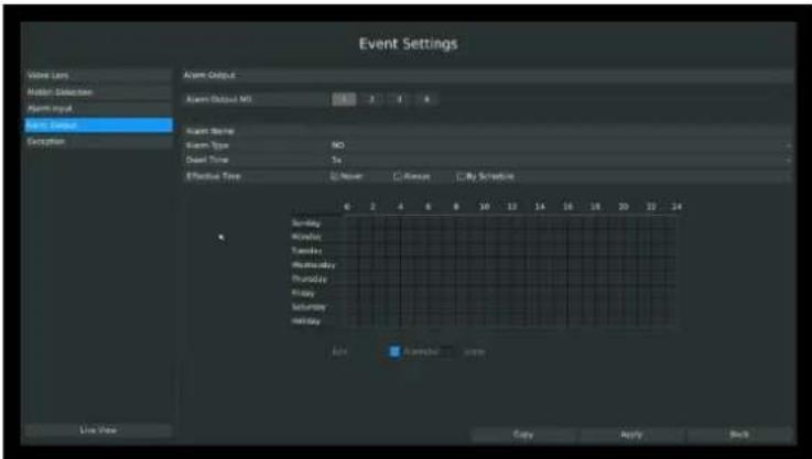
text_image
Event Settings Volume Lamp Folder: Selectbox Alarm Input Alarm Setup Exception Alarm Output Alarm Output MS 3 1 4 Alarm Name Alarm Type NO Door Time Se Effective Time Never Always By Signature Sunday Wednesday Tuesday Wednesday Thursday Friday Saturday Monday Add Apply Apply Copy Apply Back Live NowF-3.5.22
Step 2. Set Alarm output channel, Alarm Name, Alarm Type and Record Channels:
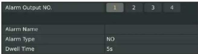
text_image
Alarm Output NO. 1 2 3 4 Alarm Name Alarm Type NO Dwell Time 5s[Alarm Output NO]: The channel which will output the alarm signal;
[Alarm Name]: Set a name for the alarm;
[Alarm Type]: Select alarm type: NO or NC;
[Dwell Time]: Set the output time for alarm, if that is too long when alarm out is outputting, you can select the Manually Clear to stop it.
Step3. Select Effective Time for alarm output
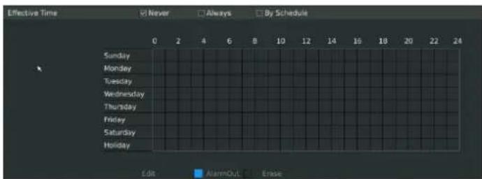
text_image
Effective Time Never Always By Schedule Sunday Monday Tuesday Wednesday Thursday Friday Saturday Holiday Edit AlarmOUT ErrorF-3.5.23
You can set three different modes for effective time:
[Never]: Will have no action triggered if it is checked;
[Always]: Will always trigger the action if checked;
[By Schedule]: Will take effect by the schedule you set.
If you choose By Schedule, you need to set schedule by 1.drag the mouse on the time schedule area or 2.by click the "Edit Time" button.
Lastly need to APPLY these settings to take effect.
3.5.5 Exception
Milesight NVR support exception alarm hint for1. Network Disconnected; 2.HDD Full; 3.Record Fail; 4.HDD Error;
Step1. Enter Exception by clicking Main Menu-Event-Exception;
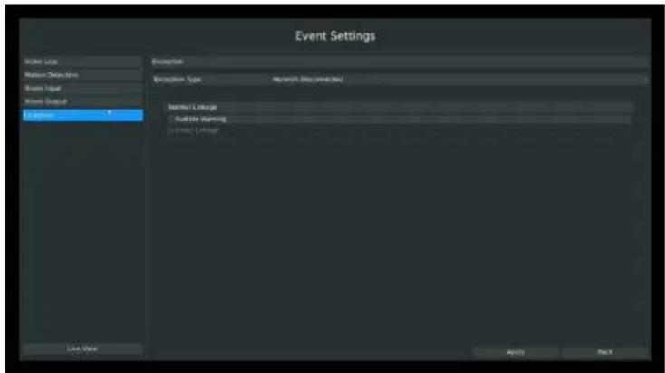
text_image
Event Settings Order Loss Motion Detection Board Input Power Output In Response Exception Navigation Type: Network (Disconnected) Network Linkage Audio Warning System Linkage Live View Apply NextF-3.5.24
Step2. Select Exception Type;
There are 4 kinds of alarm type:
[Network Disconnected]: Lost of network;
[HDD Full]: When HDD is full. It usually happened when Recycle Mode is OFF.
[Record Fail]: When record Failed. Including HDD Error, HDD Full, no HDD and so on.
[HDD Error]: When HDD Error.
Step3. Select alarm type;
[Audible Warning]: Will trigger audio alarm if checked;
[Email Linkage]: Will send alarm Email if checked.
3.6 Status
You can have a quick view of the information of the device, network, camera, disk and event. This part is only for your rapid reference. If you want to make any configuration, please go to corresponding parts accordingly.
3.6.1 Device Information
Step: Enter Device information menu by clicking Main MStatus→Device Information
It will show you information in F-3.6.1, including: Device ID, Device Name, Hardware Version, Software Version, and Serial Number.
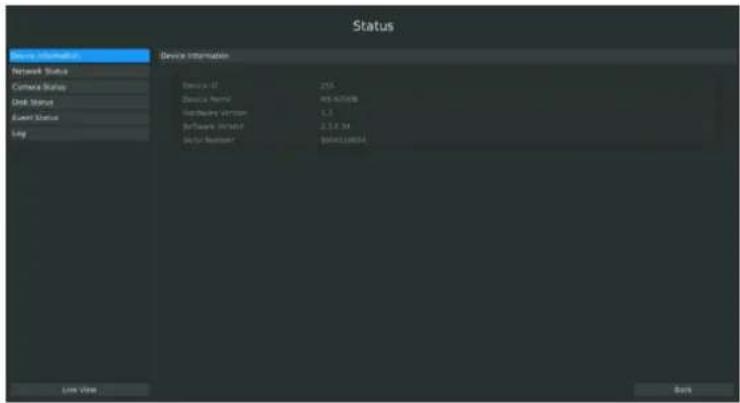
text_image
Status Device Information Network Status Camera Status Disk Status User Status Key Device Information Device ID: 255 Device Name: MS-00108 User Device Version: 1.3 Software Version: 2.3.4.34 User Number: 0004128864 Live View BansF-3.6.1
3.6.2 Network Status
Step: Enter Network Status menu by clicking Main MStatus→Network Status
It will show you information in F-3.6.2, including: Connection, Mode, DHCP, MTU(B), IP Address, Net mask, Gateway, MAC, Preferred DNS Server, Alternate DNS Server, Receive Rate, and Send Rate.
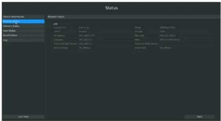
text_image
Status Device Information Event Status Camera Status Event Status Event Lab Connection Link to us Route HSPeng, Pull Link IP Address 102.345.3.178 Address 206.253.216.6 Código 08 To 49.5801.9 Functional Data Server 102.345.3.1 Functional Data Server Small Data 48.188000 Line View BackF-3.6.2
3.6.3 Camera Status
Step: Enter camera status menu by clicking Main Menu→Status→Camera Status
It will show you information in F-3.6.3, including: Channel, Name, Enable, IP Address, Record,
Frame Rate, Bit rate, Resolution and Status. The PoE Channel Status is only for PoE NVR, it will show you the connection status of PoE ports.
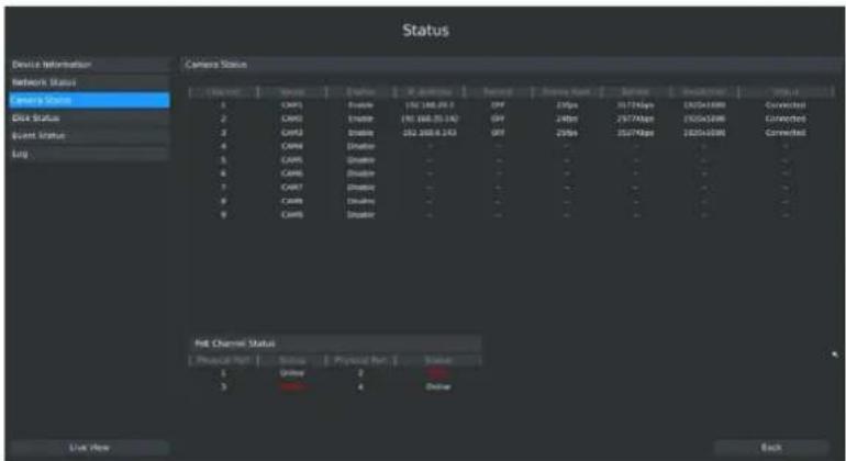
text_image
Status Device Information Network Status Camera Status 1 2 3 4 5 6 7 8 9 Hot Channel Status Physical Port | Status | Physical Port | Status | 1 2 3 4 Live Now Back 1 2 3 4 Live Now Close 1 2 3 4 Live Now Close 1 2 3 4 Live Now Close 1 2 3 4 Live Now Close 1 2 3 4 Live Now Close 1 2 3 4 Live Now Close 1 2 3 4 Live NowF-3.6.3
3.6.4 Disk Status
Step: Enter disk status menu by clicking Main Menu→Status→Disk Status
It will show you information in F-3.6.4, including: Port, Vendor, Status, Total(GB), Free(GB), HDD Type, In Use, and Recycle Mode. You can see the Total Capacity (GB) and Available Capacity (GB) as below:
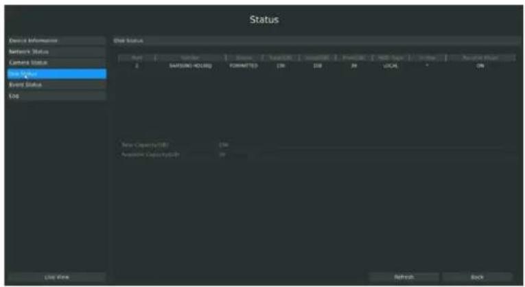
text_image
Status Device Information Network Status Camera Status Event Status Event Status 120 File Status Port Order State Total/CLK Sound/CLK Format NAS Type Inbit Paractin Point 2 SAFSUMI HOLD FORMATTED CM DIB RN LOCAL ON Data Capacity(GB) CM Paractin Capacity(GB) IN Use Open Refresh BackF-3.6.4
3.6.5 Event Status
3.6.5.1 Alarm Status
Step: Enter alarm page by clicking Main Menu→status→Event Status
It will show you the Alarm Input List in F-3.6.5.
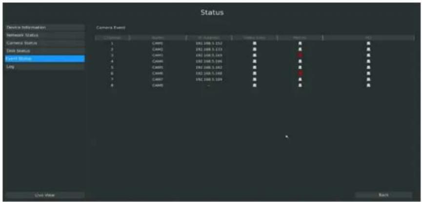
text_image
Status Device Information Network Status Camera Status Disk Status Event Status Camera Event 1 CAMR0 192.188.5.132 CAMR1 192.188.5.133 CAMR2 192.188.5.134 CAMR3 192.188.5.135 CAMR4 192.188.5.136 CAMR5 192.188.5.137 CAMR6 192.188.5.138 CAMR7 192.188.5.139 CAMR8 - BackF-3.6.5
3.6.5.2 Camera Event Status
Step: Enter camera event page by clicking Main Menu→Status→Event Status.
It will show you the camera event status in F-3.6.6. If the shows in red, it means the corresponding project is active.
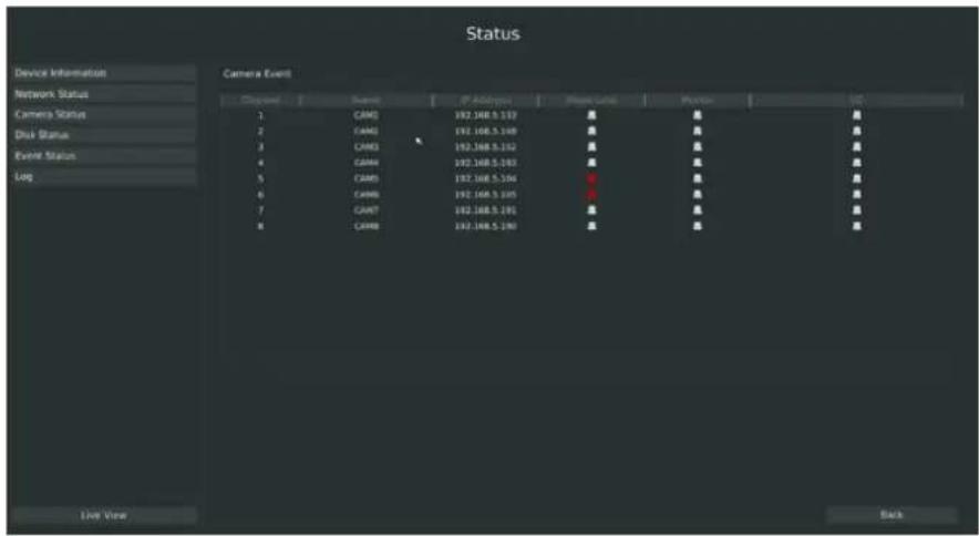
text_image
Status Device Information Network Status Camera Event Channel Status P-Add/Import Please Label Punter End 1 CAM3 192.168.5.193 ■ ■ ■ 2 CAM3 192.168.5.149 ■ ■ ■ 3 CAM3 192.168.5.192 ■ ■ ■ 4 CAM4 192.168.5.193 ■ ■ ■ 5 CAM5 192.168.5.194 ■ ■ ■ 6 CAM6 192.168.5.195 ■ ■ ■ 7 CAM7 192.168.5.196 ■ ■ ■ 8 CAM8 192.168.5.197 ■ ■ ■ Live View BackF-3.6.6
3.7 Live View Settings
3.7.1 Live View
Watching a Live View
There are multiple icons on each channel displayed in live view mode, indicating the recording and alarm status of the channel.
| Icons | Descriptions |
 | Indicates video loss |
 | Indicates motion detection alarm |
 | Indicates the current channel is recording. The recording may have been st manually, from a schedule, motion detection, alarm, and/or triggered from motion and alarm. |
| [6H87] | Indicates exception alarm and recording. |
Use the Right Button of the Mouse in Live View
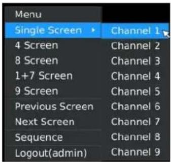
text_image
Menu Single Screen ▶ Channel 1 4 Screen Channel 2 8 Screen Channel 3 1+7 Screen Channel 4 9 Screen Channel 5 Previous Screen Channel 6 Next Screen Channel 7 Sequence Channel 8 Logout(admin) Channel 9F-3.7.1
| Item | Description |
| Menu | Enter main menu |
| Single Screen | The channel chosen will spread the whole screen. You could also reve. function by double clicking the channel |
| Sub Screen Ctrl | Switch to sub screen to operate(only for MS-N8000 series) |
| Previous Screen | Switch to the previous screen |
| Next Screen | Switch to the next screen |
| Sequence | Enable single/multi-screen cruise in live view mode |
| Sub Sequence | Enable single/multi-screen cruise for sub screen(only for MS-N8000 seri- |
| Logout | Click it to log out current user account |
Quick Operation for Live View
Enter the live view interface; left click the channel, the quick menu will appear. Quick menu operations include recording manually, snapshot, PTZ, audio, digital zoom, and image configuration.
Quick Menu Instructions for Main Output Live View

natural_image
Toolbar with eight grayscale icons representing camera, photo, video, search, image, and X (no text or labels)| Icon | Description | Icon | Description | Icon | description |
 | Manually recording |  | Imageconfigure |  | PTZ Control |
| Sound on/off | ElectronicAmplification | Snapshot manually | |||
| Close |
3.7.2 Layout Configuration
Step1. Enter layout configuration menu by clicking Main Menu → Live View → Layout configuration
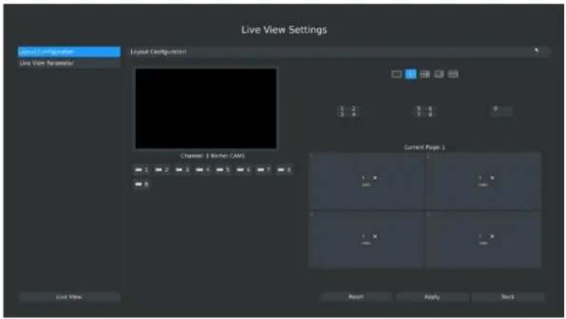
text_image
Live View Settings Input Configuration Live View Parameter Output Configuration 1 2 3 4 5 6 7 8 9 Current Pages 1 Reset Apply Back Live ViewF-3.7.2
You can choose single screen/4/8/1+7/9/12/1+11/14/16/32 screens for layout configuration according to the model and your need.
Step2. Click to close a channel, or click a desired channel (shown F-3.7.3) to add in and then click "Apply" to confirm settings. Click "Reset" to reset the layout.

text_image
1 2 3 4 5 6 7 8F-3.7.3
3.7.3 Live View Parameter
Live View Parameters Settings
Step: Enter the more setting interface by clicking Main Menu→Live View→Live View Parameter
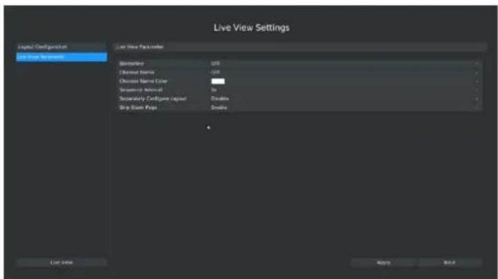
text_image
Live View Settings Legend Configuration Live View Parameters Live View Parameter Description: GIF Character Name: -101 Character Name Color: 0 Sequence Eventual: 0 Sequence Configne Layer: 0 Skip Book Page: 0 List size Apply BackF-3.7.4
| Item | Description |
| Borderline | Borderline ON/OFF |
| Channel Name | Display the channel name |
| Channel Name Color | To change the color of the channel name |
| Sequence Interval | Set sequence interval in live view mode |
| Separately Configure Layout | To configure channel order of all layouts respectively |
| Skip Blank Page | Skip blank page in sequence mode |
3.8 System Settings
3.8.1 General Setting
Step: Enter general menu by clicking Main Menu→System Settings→General
To setup the general parameters of NVR, including modify the host name, device ID, select resolution, and set system time manually, etc.
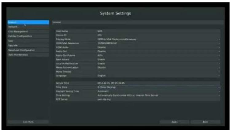
text_image
System Settings General Networks Core Management Portfolio Configuration User Upgrade Save/Load Configuration Auto Maintenance Media Name: MXP Device ID: 205 Display Mode: HDMI & VGA Display software HDMI USA Investments: 1338519895762 HDMI Audio: 34000 Audio Out: Drive Audio Slot Volume: 40% Base Word: Enable Local Authentication: Enable Home Authentication: DoCTR Home Workload: ... Language: English Server Zone: 2014.12.15, 09:05:34:45 Time Zone: 6 Chinese Design Design Setting Zone: Automatic Time Setting: Automatically Synchroset With an Internet Base Server MIP Server: post-My.org Live Now Apply BackF-3.8.1
3.8.2 Network Settings
3.8.2.1 Basic Configuration
Step: Enter the network setting menu to set the network parameters by clicking Main Menu→System Settings→Network, select "Basic" page
Basic configuration includes working mode, IP address, subnet mask, gateway, MTU, DNS server, Internal NIC IPv4 Address, etc.

text_image
System Settings General Service One Management Holiday Configuration Unit Parameters Specialized Configuration Auto Maintenance Base PPM0 DNS5 Net FTP Maps Networking Note Multi address LAN1 - DHCP frakes IP Address 192.368 8 - 178 Submit Mode 355.250.254.0 Saturny 192.368 8 - 1 Preferred DNS Server 192.368 8 - 1 Alternative DNS Server MTU(syle) (300) MAC Address 06.54.05.05.07.05 LAN2 - Enable (1) 1.000 IP Address C 4 4 4 4 Submit Mode D 2 2 2 2 Satry May D 2 2 2 2 Preferred DNS Server Alternative DNS Server MTU(syle) (300) MAC Address 06.54.05.05.07.05 Use Now Apply OKF-3.8.2
Note:
-
Check the DHCP check-box if there has a DHCP server running in networks.
-
The valid range of MTU is 500\~9676.
-
Do not input an IP address conflict with another device.
-
Working mode option is only for NVR 7000/8000 series. Internal NIC IPv4 Address is only for PoE NVR.
3.8.2.2 PPPoE Configuration
Step: Enter PPPoE menu by clicking Main MenuSystem Settings→Network. Select "PPPOE" page
Check the PPPoE check-box to enable the feature, and then input user name, password and confirm password for PPPoE access.
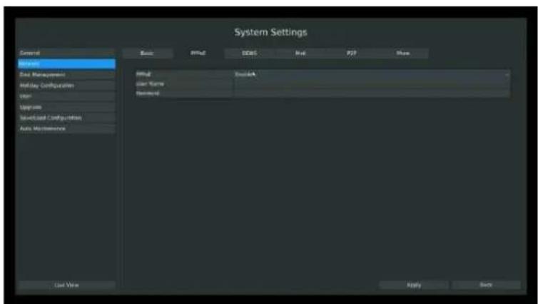
text_image
System Settings General Manager End Management Mailay Configuration Enter Upgrade Save/Load Configuration Auto Maintenance Edit View Basic Diffus DDGS Ref PDF Share Diffus Send Name Password Send Name Send Name Send Name Send Name Send Name Send Name Send Name Send Name Send Name Send Name Send Name Send Name Send Name Send Name Send Name Send Name Send Name Send Name Send Name Send Name Send Name Send Name Send Name Send Name Send Name Send Name Send Name Send Name Send Name Send Name Send Name Send Name Send Name Send NameF-3.8.3
Note:
- PPPoE user name and password can be obtained from your service provider. Once the setup is completed, a connected status will be shown.
- PPPoE function is not available for 4K/H.265 series NVR.
3.8.2.3 DDNS Configuration
If your NVR is setup to use PPPoE to connect public network, you may need to use DDNS (Dynamic Domain Name System) to solve the problems from dynamic IP address.
Step: Enter DDNS configuration menu by clicking Main Menu → System Settings → Network, Select "DDNS" page
Check the DDNS check-box to enable the feature. Select "DDNS Server", and input user name, password and host name, and then confirm.
Click [Apply] for application.
Note:
"host name" can use letters, figures and hyphen (-) and must begin with letters.
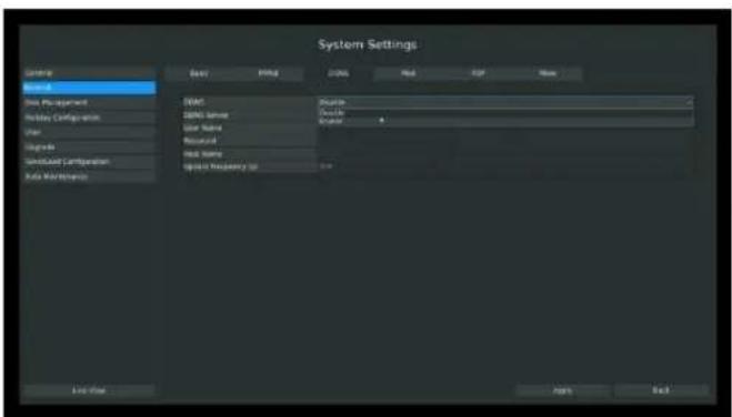
text_image
System Settings System Name Data Management Hardware Configuration User Categories ServiceAccess Configuration Auto Maintenance View: DIME: Time Data Name Resource Read Name Update Frequency (r) Status: Data Description: Data Resource: Read Name: Update Frequency (r) End Data Next NextF-3.8.4
3.8.2.4 EMAIL Configuration
Step: Enter Email configuration page by clicking Main Menu → System Settings → Network →
Set the Sender E-mail Address, User Name, Password, and SMTP Server:
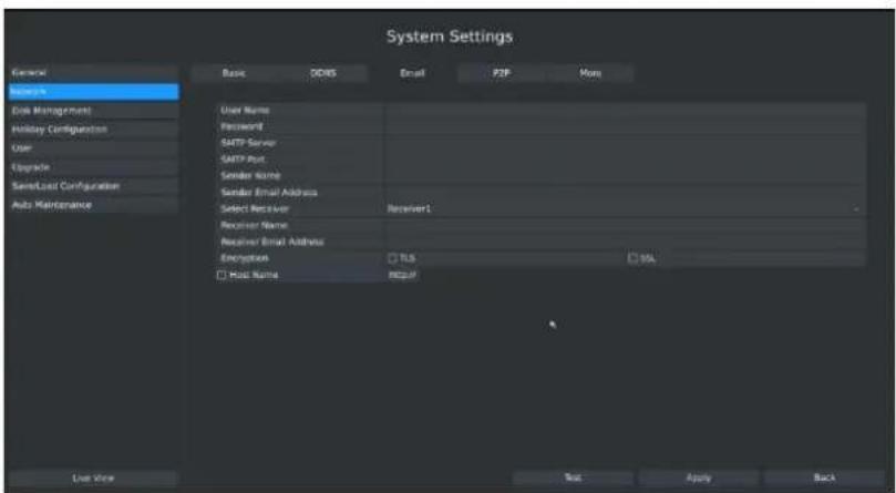
text_image
System Settings General Basic DDNS Email P2F More User Name Password SMTP Server SMTP Port Sender Name Sender Email Address Select Receiver Receiver1 Receiver Name Receiver Email Address Encryption TLS SSL Host Name Export Last View Test Apply BackF-3.8.5
[User name]: The E-mail address you choose to send emails.
[Password]: The password of the E-mail.
[SMTP Server]: The SMTP Server of your E-mail.
[Port]: The port of SMTP Server, it's usually 25.
[Sender Name]: Named by yourself for the Sender E-mail.
[Sender E-mail Address]: It must be same with [User name].
[Select Receiver]: You can have 3 receivers once.
[Receiver Name]: Named by yourself for the Receiver E-mail.
[Receiver E-mail Address]: E-mail Address for the receivers.
[Encryption]: Security Protocol of email sending, includes TLS and SSL.
[Host Name]: For attaching URL when sending emails. Please enable SSL/TLS according to actual mailbox. (Some SMTP server needs to secure connection)
Select [Test] to check if the Mail function is workable
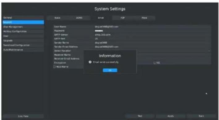
text_image
System Settings General Basis GOINS Email APP More User User Name dsg@400@163.com Password ******** SMTP Server kmp.163.com SMTP Link 25 Sender Name dsg@400 Sender Event Address dsg@400@163.com Select Protocol Received Name Received Email Address Encryption OK Information ● Email send successfully OK Live Now Text Apply HelpF-3.8.6
Note:
-
You will get a screenshot every time for motion detection email sending;
-
If you use a port forward IP of NVR for the Host Name, please type the entire address including the port;
-
If click the URL in the alarm emails within 10 minutes, you can visit NVR Web GUI without login.
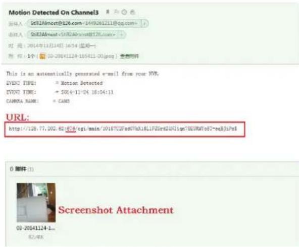
text_image
Motion Detected On Channel3 输入: Set12Almost@126.com=1449261211@qq.com= 输入: Set12Almost<5002Almost@126.com> 时间: 2014年12月14日 16:54 (超始一) 附件: 1个: 03-20141124-105411-00(pcc) 查看附件 This is an automatically generated e-mail from your HTML. EVENT TYPE: = Motion Detected EVENT TIME: = 2014-11-04 18:54:11 CAMERA NAME: = CAMS URL: http://126.77.000-851676/cgi/main/10107CZPsdSTVhA1BLLPZErdAUNlqn78EWRTo57-eq8jlsPe$ 0 附件(1) Screenshot Attachment 03-20141124-1... 82.48XF-3.8.7
3.8.2.5 P2P
You can use M-VMS to watch the remote live view by P2P. With the introduction of P2P, you can watch the NVR Live view from WAN without do any port forwarding on the router.
Right click on the live view and choose Menu→System→Network→P2P, you will see the image like below:
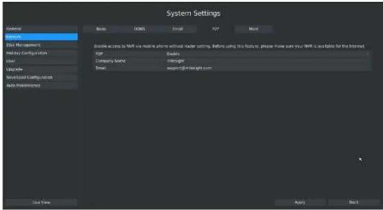
text_image
System Settings External Network Disk Management Holiday Configuration User Upgrade Synchronized Configuration Auto Maintenance Enable access to NVP via mobile phone without router setting. Before using this feature, please make sure your NVP is available for the Internet. NVP Guides Company Name: microgrc Datal: www.nip.org/ Live View Apply NextF-3.8.8
Step1. Choose "Enable" from the drop-down list of "P2P";
Step2. Fill in your Company Name or your Individual Name in the "Company Name";
Step3. Fill in your Email address in the "Email" for active;
Step4. Apply the settings.
Note:
Activation works as soon as the page shows "Save Successfully" as the following picture. It is no need to contact Milesight to activate again.
text_image
System Settings Setup File Management Network Configuration Edit Database Database Command Auto Reference Form 1000000000000000000000000000000000000000000000000000000000000000000000000000000000000000000000000 Information ASP Logistic Accessibility OK Help Back Next3.8.2.6 More
Step: Enter More configuration page by clicking Main Mem→System Settings→Network→More
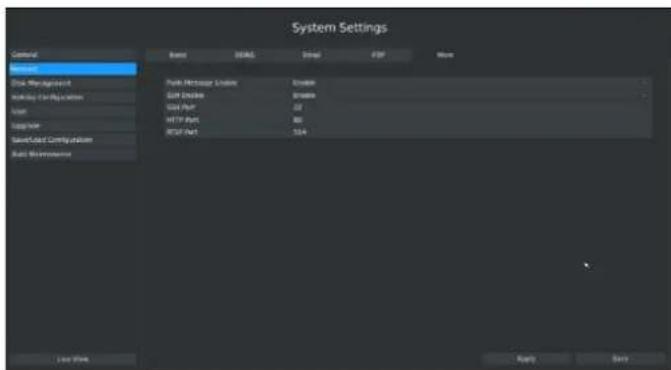
text_image
System Settings Central System Start Management Starting Configuration Start Support Start Load Configuration Start Maintenance Base DEGA Split FDP None Park Configuration Update Edit GPT Enable Enable Start Part 32 NET Part 80 NAT Part 104 Last Work Apply NextF-3.8.9
Push Message Enable
With this option enabled, you can receive the alarm message on the mobile application(M-VMS).
SSH Port Setting
Secure Shell (SSH) has many functions; it can replace Telnet and also provides a secure channel for FTP, POP, even for PPP.
Note:
The default SSH port is 22.
HTTP Port Setting
The default HTTP port is 80. Please modify HTTP ports according to actual application.
Note:
- The default HTTP port for IE browser is 80.
- HTTP port is used for remote network access.
- The valid range of HTTP port is 80 or 1024\~65535.
RTSP Port Setting
Real Time Streaming Protocol (RTSP) is an application layer protocol in TCP/IP protocol system.
The default RTSP port is 554. Please modify RTSP port according to actual application.
Note:
- RTSP port is used for remote network live view.
- The valid range of RTSP port is 554 or 1024\~65535.
Service Port Setting
Service port is used to remote access when add NVR by mobile device.
The default service port is 1100. Please modify service port according to actual application.
Note:
- This option is not available for 4K/H.265 series NVR.
- You can add this port when using P2P/port mapping/LAN IP to add NVR, the 4K/H.265 series NVR use port 80 to add.
- When port mapping, you still need map 554 to 554. Only then you can use 1100 or 80 to watch the live view by remote WAN.
3.8.3 Disk Management
3.8.3.1 Disk Configuration
Step: Enter disk configuration menu by clicking Main Menu → System Settings → Disk Management→Configuration
Configuration page contains the basic information of the disk, see F-3.8.8. Select a disk and click [Format] to format the disk.
text_image
System Settings Standard Configuration: 0.01437 Name: Name Name: Name Type: Normal Name Type: Normal Name Type: Normal Name Type: Normal Name Type: Normal Name Type: Normal Name Type: Normal Name Type: Normal Name Type: Normal Name Type: Normal Name Type: Normal Name Type: Normal Name Type: Normal Name Type: Normal Name Type: Normal Name Type: Normal Name Type: Normal Name Type: Normal Name Type: Normal Name Type: Normal Name Type: NormalF-3.8.10
3.8.3.2 S.M.A.R.T Detection
Step: Enter S.M.A.R.T configure page by clicking Main Menu → System Settings → Disk Management→S.M.A.R.T
S.M.A.R.T detection is a monitoring system of HDD that detects and reports on various indicators of anticipating failures of HDD.
You can command S.M.A.R.T self-checking function to check the HDD status.
Select "Test type", and click "apply" for S.M.A.R.T detection.

text_image
System Settings Configuration: SMA-5T File Path: 1. New, New, New Data 2. New, New Data 3. New, New Data 4. New, New Data 5. New, New Data 6. New, New Data 7. New, New Data 8. New, New Data 9. New, New Data 10. New, New Data 11. New, New Data 12. New, New Data 13. New, New Data 14. New, New Data 15. New, New Data 16. New, New Data 17. New, New Data 18. New, New Data 19. New, New Data 20. New, New Data 21. New, New Data 22. New, New Data 23. New, New Data 24. New, New Data 25. New, New Data 26. New, New Data 27. New, New Data 28. New, New Data 29. New, New Data 30. New, New Data 31. New, New Data 32. New, New Data 33. New, New Data 34. New, New Data 35. New, New Data 36. New, New Data 37. New, New Data 38. New, New Data 39. New, New Data 40. New, New Data 41. New, New Data 42. New, New Data 43. New, New Data 44. New, New Data 45. New, New Data 46. New, New Data 47. New, New Data 48. New, New Data 49. New, New Data 50. New, New Data 51. New, New Data 52. New, New Data 53. New, New Data 54. New, New Data 55. New, New Data 56. New, New Data 57. New, New Data 58. New, New Data 59. New, New Data 60. New, New Data 61. New, New Data 62. New, New Data 63. New, New Data 64. New, New Data 65. New, New Data 66. New, New Data 67. New, New Data 68. New, New Data 69. New, New Data 70. New, New Data 71. New, New Data 72. New, New Data 73. New, New Data 74. New, New Data 75. New, New Data 76. New, New Data 77. New, New Data 78. New, New Data 79. New, New Data 80. New, New Data 81. New, New Data 82. New, New Data 83. New, New Data 84. New, New Data 85. New, New Data 86. New, New Data 87. New, New Data 88. New, New Data 89. New, New Data 90. New, New Data 91. New, New Data 92. New, New Data 93. New, New Data 94. New, New Data 95. New, New Data 96. New, New Data 97. New, New Data 98. New, New Data 99. New, New Data 100. N/AF-3.8.11
Note:
- Test type has [fast] and [full] options.
- Test Status can be [status good], [status bad] and [bad tracks exist].
- Test result can be [passed] or [failed].
3.8.4 Holiday Configuration
It can configure the record or image capture schedule for holidays of the current year. Step1. Enter holiday setting menu by clicking System Setting Holiday Configuration.
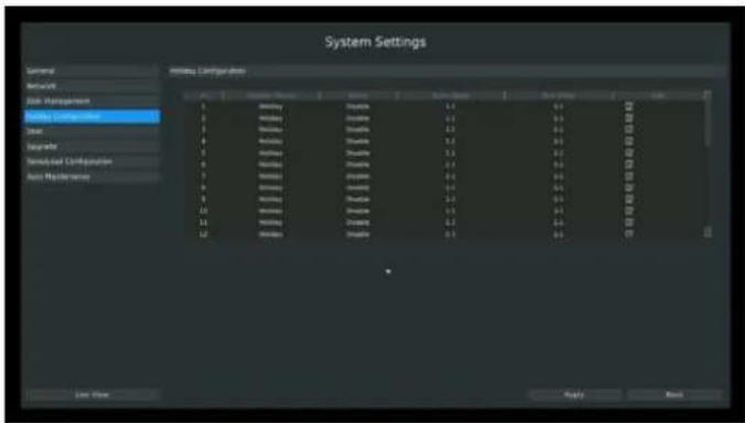
text_image
System Settings General Networks Data Management Setting Configuration Urban Suburban Townsend Configuration Base Properties Initiating Configuration 1 2 3 4 5 6 7 8 9 10 11 12 Setting Configuration 1.1 1.2 1.3 1.4 1.5 1.6 1.7 1.8 1.9 2.0 2.1 2.2 2.3 2.4 2.5 2.6 2.7 2.8 2.9 3.0 3.1 3.2 3.3 3.4 3.5 3.6 3.7 3.8 3.9 4.0 4.1 4.2 4.3 4.4 4.5 4.6 4.7 4.8 4.9 5.0 5.1 5.2 5.3 5.4 5.5 5.6 5.7 5.8 5.9 6.0 6.1 6.2 6.3 6.4 6.5 6.6 6.7 6.8 6.9 7.0F-3.8.12
Step2. Edit the holiday schedule.
Click to open holiday configuration page to modify holiday name, check the 'Holiday Enable' check-box, and then select [style] to setup Start/End date. Then click [OK] to save the configuration and return to holiday configuration page. Click [Apply] to confirm settings.
Note:
There are Month, Week and Date in "Style" mode.
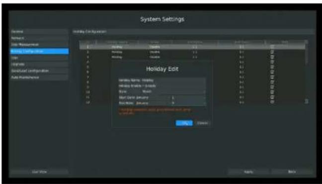
text_image
System Settings General Name: Size: Moisture Balance Setting Order Order Name: 120mm Balance Name: 120mm Balance Date: January Balance Month: January Holiday Edit Balance Name: 120mm Balance Date: January Balance Month: January Holiday Edit Balance Name: 120mm Balance Date: January Balance Month: JanuaryF-3.8.13
3.8.5 User Account Settings
Add New User
Step1. Enter user setting menu by clicking Main Menu→System Settings→User.
Click [Add] to enter add user menu, input information for the new user, select user level and click [OK].
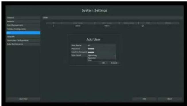
text_image
System Settings Add User Name: 101 Password: ****** Customer Address: ****** User Location: Operating Address: OK Cancel Add NextF-3.8.14
Note:
- If the NVR firmware version out of the factory is xx.7.0.6 or above, the default user name is "admin" and the default password is "ms1234";
- If the NVR firmware is upgraded to xx.7.0.6 or above from a lower version, the default password will turn to "ms1234" after a reset, or it will keep the old default password "123456";
- If the NVR firmware version is below xx.7.0.6, the default user name is "admin" and the default password is "123465".
Step2. Set user privileges
Select the user that has been added and click [limit] button to enter user privilege menu.
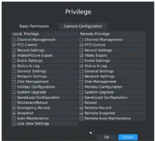
text_image
Privilege Basic Permission Camera Configuration Local Privilege Remote Privilege Channel Management Channel Management PTZ Control PTZ Control Record Settings Record Settings Video/Picture Export Video Export Event Settings Event Settings Status & Log Status & Log General Settings General Settings Network Settings Network Settings Disk Management Disk Management Holiday Configuration Holiday Configuration System Upgrade System Upgrade Save/Load Configuration Save/Load Configuration Shutdown/Reboot Reboot Emergency Record Remote Record Snapshot Remote Snapshot Auto Maintenance Remote Auto Maintenance Live View Settings OK Cancel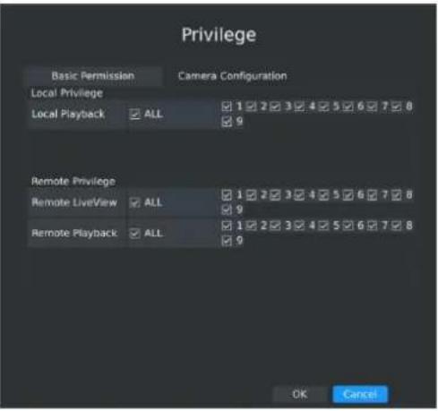
text_image
Privilege Basic Permission Camera Configuration Local Privilege Local Playback ALL 1 2 3 4 5 6 7 8 9 Remote Privilege Remote LiveView ALL 1 2 3 4 5 6 7 8 9 Remote Playback ALL 1 2 3 4 5 6 7 8 9 OK CancelF-3.8.15
Step3. Click to delete a user.
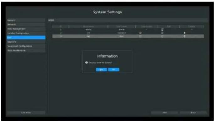
text_image
System Settings General Network Risk Management Pre Libya Configuration Key Parameters Save/Replace Configuration Auto Maintenance System 0.1 0.2 0.3 0.4 0.5 0.6 0.7 0.8 0.9 1 2 3 4 5 6 7 8 9 10 11 12 13 14 15 16 17 18 19 20 21 22 23 24 25 26 27 28 29 30 31 32 33 34 35 36 37 38 39 40 41 42 43 44 45 46 47 48 49 50 51 52 53 54 55 56 57 58 59 60 61 62 63 64 65 66 67 68 69 70 71 72 73 74 75 76 77 78 79 80 81 82 83 84 85 86 87 88 89 90 91 92 93 94 95 96 97 98 99 100F-3.8.16
Step4. Click to edit a user.
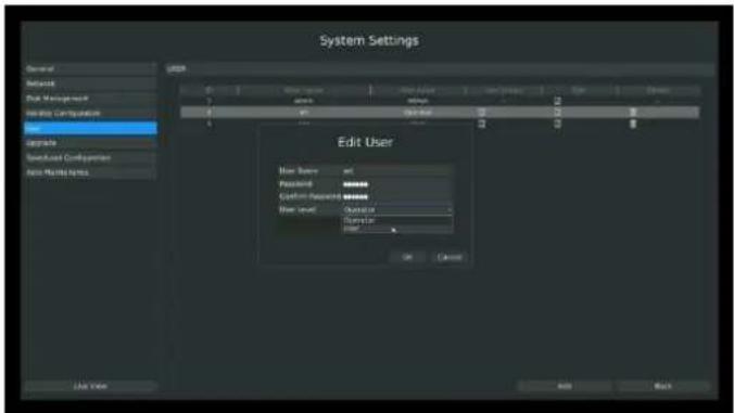
text_image
System Settings General Default Risk Management Risk Configuration User Upgrade Speed/User Configurations Auto Platform Options Edit User New User Forward Custom Request New User Order OK Cancel Add BackF-3.8.17
3.8.6 Upgrade
Your NVR supports firmware upgrade.
Step1. Enter upgrade menu by clicking Main MenSystem Settings→Upgrade.
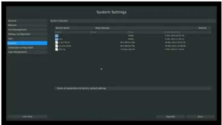
text_image
System Settings General Networks Risk Management Holiday Configuration Main System Sensified Configuration Auto Maintenance System Upgrade Device Name Power Savings Default Name 10000000000000000000000000000000000000000000000000000000000000000000000000000000000000000000000000000 Date: 25 Dec 2014 16:37:34 Date: 25 Dec 2014 13:32:52 Date: 25 Dec 2014 15:33:58 Date: 25 Dec 2014 15:33:58 Date: 25 Dec 2014 15:33:58 Date: 25 Dec 2014 15:33:58 Date: 25 Dec 2014 15:33:58 Date: 25 Dec 2014 15.33:58 Date: 25 Dec 2014 15.33:58 Date: 25 Dec 2014 15.33:58 Date: 25 Dec 2014 15.33:58 Date: 25 Dec 2014 15.33:58 Date: 25 Dec 2024 16:37:34 Date: 25 Dec 2024 13:32:52 Date: 25 Dec 2024 15:33:58 Date: 25 Dec 2024 15:33:58 Date: 25 Dec 2024 15.33:58 Date: 25 Dec 2024 15.33:58 Date: 25 Dec 2024 15.33:58 Date: 25 Dec 2024 15.33:58 Date: 25 Dec 2024 15.33:58 Date: 25 Dec 2014 16:37:34 Date: 25 Dec 2014 16:37:34 Date: 25 Dec 2014 16:37:34 Date: 25 Dec 2014 16:37:34 Date: 25 Dec 2014 16:37:34 Date: 25 Dec 2014 16.37:34 Date: 25 Dec 2014 16.37:34 Date: 25 Dec 2014 16.37:34 Date: 25 Dec 2014 16.37:34 Date: 25 Dec 2014 16.37:34 Date: 25 Dec 2024 16.37:34 Date: 25 Dec 2024 16.37:34 Date: 25 Dec 2024 16.37:34 Date: 25 Dec 2024 16.37:34 Date: 25 Dec 2024 16.37:34 Date: 26 Dec 2014 16.37:34 Date: 26 Dec 2014 16.37:34 Date: 26 Dec 2014 16.37:34 Date: 26 Dec 2014 16.37:34 Date: 26 Dec 2014 16.37:34 Date: 27 Dec 2014 16.37:34 Date: 27 Dec 2014 16.37:34 Date: 27 Dec 2014 16.37:34 Date: 27 Dec 2014 16.37:34 Date: 27 Dec 2014 16.37:34F-3.8.18
Step2. Search for device, and select the .bin file.
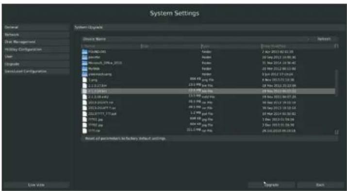
text_image
System Settings General Network Dist Management Holding Configuration User Upgrade ShareClass Configuration System Upgrade Device Name Name File Size Form Date Required Refresh 12 Apr 2013 02:03:05 12 Apr 2013 03:03:06 11 May 2014 08:06:45 11 May 2014 09:06:46 11 May 2014 10:06:47 11 May 2014 11:06:48 11 May 2014 12:06:49 11 May 2014 13:06:50 11 May 2014 14:06:51 11 May 2014 15:06:52 11 May 2014 16:06:53 11 May 2014 17:06:54 11 May 2014 18:06:55 11 May 2014 19:06:56 11 May 2014 20:06:57 11 May 2014 21:06:58 11 May 2014 22:06:59 11 May 2014 23:06:60 11 May 2014 24:06:61 11 May 2014 25:06:62 11 May 2014 26:06:63 11 May 2014 27:06:64 11 May 2014 28:06:65 11 May 2014 29:06:66 11 May 2014 30:06:67 11 May 2014 31:06:68 11 May 2014 32:06:69 11 May 2014 33:06:70 11 May 2014 34:06:71 11 May 2014 35:06:72 11 May 2014 36:06:73 11 May 2014 37:06:74 11 May 2014 38:06:75 11 May 2014 39:06:76 11 May 2014 40:06:77 11 May 2014 41:06:78 11 May 2014 42:06:79 11 May 2014 43:06:80 11 May 2014 44:06:81 11 May 2014 45:06:82 11 May 2014 46:06:83 11 May 2014 47:06:84 11 May 2014 48:06:85 11 May 2014 49:06:86 11 May 2014 50:06:87 11 May 2014 51:06:88 11 May 2014 52:06:89 Mean of parameters to factory default settings. Live Now Upgrade NextF-3.8.19
Step3. Click [Upgrade] button to confirm the upgrade.
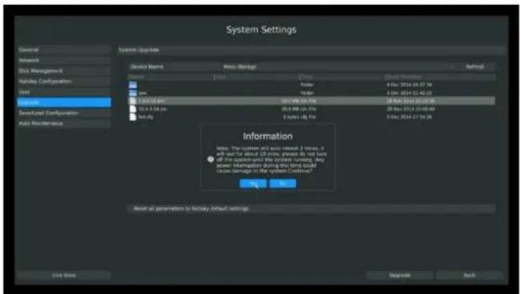
text_image
System Settings General Network Grid Management Mainley Configuration Unit Support Save/Used Configuration Auto Maintenance System Options Device Name Main Manager Name Mode Speed Time Address Manager 0.00: 3524.19.37.39 0.00: 3524.19.40.22 0.00: 3524.19.41.06 0.00: 3524.19.42.08 0.00: 3524.19.43.09 0.00: 3524.19.44.10 0.00: 3524.19.45.11 0.00: 3524.19.46.12 0.00: 3524.19.47.13 0.00: 3524.19.48.14 0.00: 3524.19.49.15 0.00: 3524.19.50.16 0.00: 3524.19.51.17 0.00: 3524.19.52.18 0.00: 3524.19.53.19 0.00: 3524.19.54.20 Information Note: The system and audio induct 2 times, it will use for about 10 ms, please do not have all the systems and the system system, any power information during this system could cause damage to the system Continue? OK Cancel Reset all parameters to factory default settings Last Time Upgrade BackF-3.8.20
Note:
The system will auto reboot after confirming upgrade.
3.8.7 Save/Load Configuration
3.8.7.1 Backup/Restore
Your NVR supports backup and restore configuration.
Step1: Enter profile menu by clicking Main Menu → System → Save/Load Configuration→Backup/Restore.
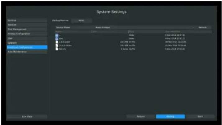
text_image
System Settings Setup Name Run Storage File Path Name Address Address Address Address Address Address Address Address Address Address Address Address Address Address Address Address Address Address Address Address Address Address Address Address Address Address Address Address Address Address Address Address Address Address Address Address Address Address Address Address Address Address Address Address Address Address Address Address Address Address Access Access Access Access Access Access Access Access Access Access Access Access Access Access Access Access Access Access Access Access Access Access Access Access Access Access Access Access Access Access Access Access Access Access Access Access Access Access Access Access Access Access Access Access Access Access Access Access Access Access accessF-3.8.21
Step2. Select a folder and then click [Backup] to export configuration to USB device.
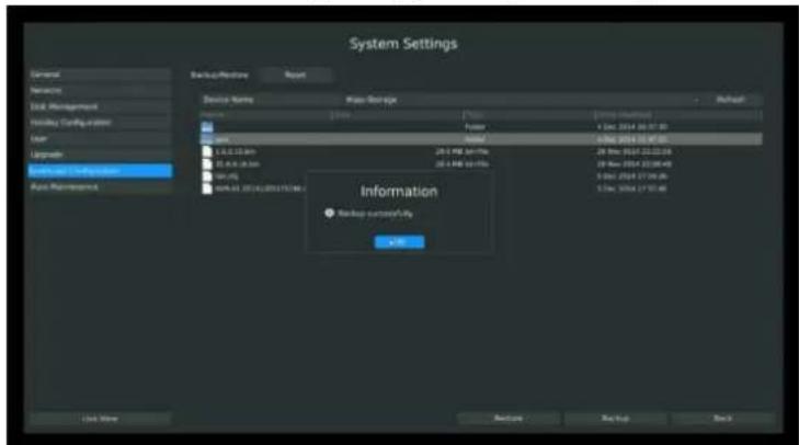
text_image
System Settings General Services Task Management Holiday Configuration User Layout Functional Configuration Auto Rebootpath Backup Status +/-F-3.8.22
Step3. Select a .cfg file and then click [Restore] to import configuration to your NVR.
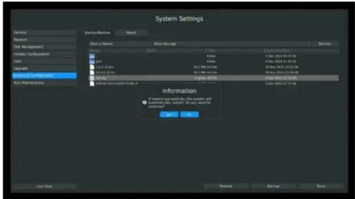
text_image
System Settings Domain Network Disk Management Holiday Configuration User Upgrade System Configurations Auto Management Backup Options Reset Device Name Memory Storage Status 100% 200% 300% 400% 500% 600% 700% 800% 900% 1000% 1100% 1200% 1300% 1400% 1500% 1600% 1700% 1800% 1900% 2000% 2100% 2200% 2300% 2400% 2500% 2600% 2700% 2800% 2900% 3000% 3100% 3200% 3300% 3400% 3500% 3600% 3700% 3800% 3900% 4000% 4100% 4200% 4300% 4400% 4500% 4600% 4700% 4800% 4900% 5000% 5100% 5200% 5300% 5400% 5500% 5600% 5700% 5800% 5900% 6000% 6100% 6200% 6300% 6400% 6500% 6600% 6700% 6800% 6900% 7000% 7100% 7200% 7300% 7400% 7500% 7600% 7700% 7800% 7900% 8000% 8100% 8200% 8300% 8400% 8500% 8600% 8700% 8800% 8900% 9000% 9100% 9200% 9300% 9400% 9500% 9600% 9700% 9800% 9900% 100 Information If restore successfully, the system will automatically adjust. Do you want to continue? OK Cancel Save Now Restore Backup BackF-3.8.23
3.8.7.2 Reset
You can reset all parameters to default settings.
Enter reset menu by clicking Main Menu→System→Save/Load Configuration→Reset. Click "yes" to confirm reset.

text_image
System Settings General Database User Management Database Configuration User Help Web Help Web Configuration Auto Maintenance Basic Preferences Reset Preview: Next to Factory Interface will create all data, please make sure you choose all the data you need before going on, try you add to access to Factory Interface Use Help OK CancelF-3.8.24
3.8.8 Auto Maintenance
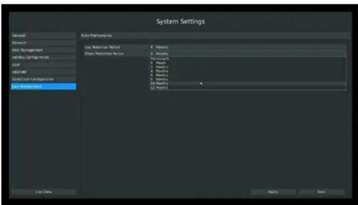
text_image
System Settings Auto Maintenance Log Adhesion Method Plan Retention Method Log Adhesion Method Plan Retention Method Log Adhesion Method Plan Retention Method Log Adhesion Method Plan Retention Method Log Adhesion Method Plan Retention Method Log Adhesion Method Plan Retention Method Log Adhesion Method Plan Retention Method Log Adhesion Method Plan Retention Method Log Adhesion Method Plan Retention Method Log Adhesion Method Plan Retention Method Log Adhesion Method Plan RetentionMethod Log Adhesion Method Plan RetentionMethod Log Adhesion Method Plan RetentionMethod Log Adhesion Method Plan RetentionMethod Log Adhesion Method Plan RetentionMethod Log Adhesion Method Plan RetentionMethod Log Adhesion Method Plan RetentionMethod Log Adhesion Method Plan RetentionMethod Log Adhesion Method Plan RetentionMethod Log Adhesion Method Plan RetentionMethod Log Adhesion Method Plan RetentionMechanical Log Adhesion Method Plan RetentionMethod Log Adhesion Method Plan RetentionMethod Log Adhesion Method Plan RetentionMethod Log Adhesion Method Plan RetentionMethod Log Adhesion Method Plan RetentionMethod Log Adhesion Method Plan RetentionMethod Log Adhesion Method Plan RetentionMethod Log Adhesion Method Plan RetentionMethod Log Adhesion Method Plan RetentionMethod Log Adhesion Method Plan RetentionTechnologyF-3.8.25
You can set the Log and Photo Retention period for Log and Photo.Once is expired, it will automatically delete by NVR. The retention period is ranged from 1 to 12 months, if you don't want those files be deleted, you can select Permanent.
3.9 Shutdown
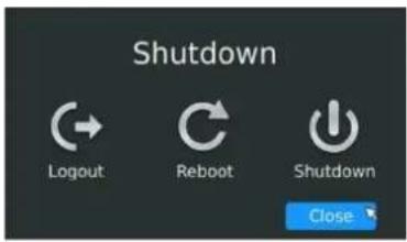
text_image
Shutdown Logout Reboot Shutdown CloseF-3.9.1
3.9.1 Logout
Click [Logout] to exit the current logon account.
3.9.2 Reboot
Click [Reboot] to restart the NVR.
3.9.3 Shutdown
Click [Shutdown] to close the NVR.
3.9.4 Close
Click [Close] to exit.
4. WEB Settings
4.1 Login
Input the user name and password.
text_image
Milesight admin LoginF-4.1.1
Note:
-
If the NVR firmware version out of the factory is xx.7.0.6 or above, the default user name is "admin" and the default password is "ms1234";
-
If the NVR firmware is upgraded to xx.7.0.6 or above from a lower version, the default password will turn to "ms1234" after a reset, or it will keep the old default password "123456";
-
If the NVR firmware version is below xx.7.0.6, the default user name is "admin" and the default password is "123465".
4.2 Live View
4.2.1 Camera List
There are multiple icons on each channel displayed in live view mode, indicating the recording and alarm status of the channel.
| Icons | Descriptions |
 | Indicates video loss |
 | Indicates motion detection alarm |
Step1: Enter Live View by clicking one window, and go for camera list.
Click to show the main stream and click to the sub stream.
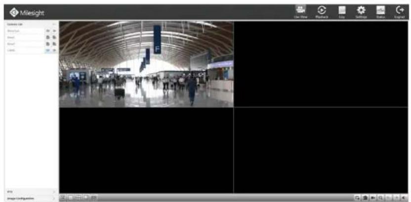
text_image
Milesight Show on Show on Show Show Show Show Show Show Show Show Show Show Show Show Show Show Show Show Show Show Show Show Show Show Show Show Show Show Show Show Show Show Show Show Show Show Show Show Show Show Show Show Show Show Show Show Show Show Show Show Show Show View Time Playback Live Settings Status LogAt Image ConfigurationF-4.1.2
Quick Operation

| Icon | Description | Icon | Description | Icon | description |
 | Stop All Live View |  | Start All Live View |  | Snapshot by manually |
 | Front Page |  | Next Page |  | Sound off/on |
 | Full Screen |  | Window 1 |  | Window 4 |
 | Window 8 | Window 9 |
4.2.2 Play View
Enter the live view interface; click Live camera List. Choose the View1 or View2 to play;
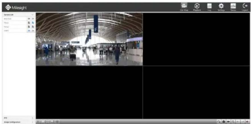
text_image
Milesight Camera List View View Playback Log Settings Session Legend Image ConfigurationF-4.1.3
4.2.3 PTZ
Enter Camera List interface by clicking Live V4WZ
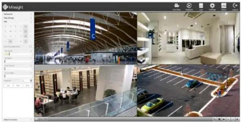
natural_image
Composite image showing four interior views of a modern building: ceiling, interior, parking lot, and street car (no visible text or symbols)F-4.1.4
4.2.4 Video Parameters
Enter Video Parameters by clicking Live Video Parameters
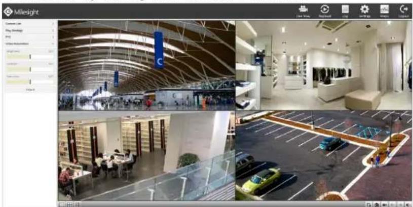
natural_image
Composite image showing four interior views of a modern building: interior view with curved architecture, interior space with service counters and parking lot, and exterior view of a modern retail or exhibition space (no visible text or symbols)F-4.1.5
4.3 Playback
To play and backup the recorded files in specified time period.
4.3.1 Playback
It can support playback according to recorded time. Play recorded files in specified time period.
Step1. Enter Video Playback Interface shown in F-4.3.1 by clicking Playback
Step2. Select a desired channel and date.
Select playback layout and channel. Click the date in red when there are recorded files of the selected channels, the record type with recording data will be show as below, and then click
to playback.
Note:
The day in red has recording files; please select the date in red to playback.
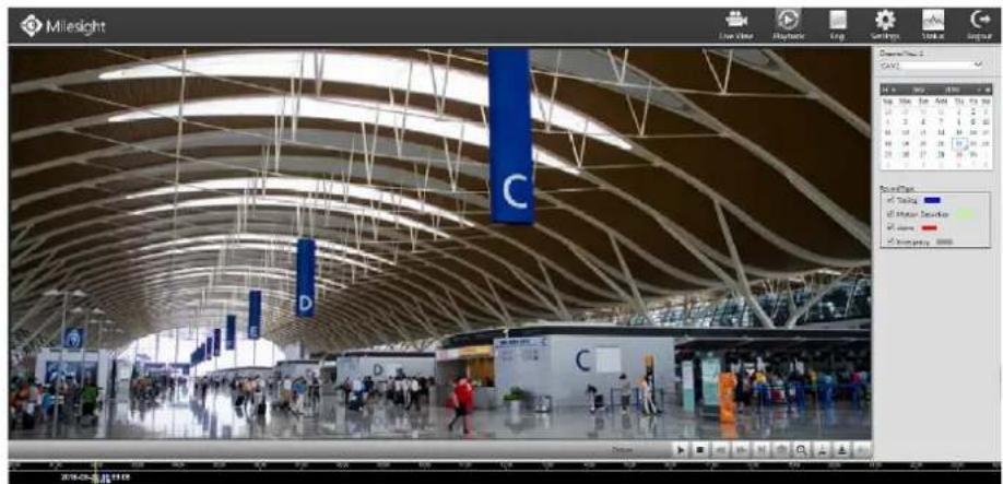
text_image
Milesight Live Video Playback Log Guideline Update Signar Description: C PAGE Top Style Top Angle Top Angle 10° 20' 30' 40' 50' 60' 70' 80' 90' 100' 110' 120' 130' 140' 150' 160' 170' 180' 190' 200' 210' 220' 230' 240' 250' 260' 270' 280' 290' 300' 310' 320' 330' 340' 350' 360' 370' 380' 390' 400' 410' 420' 430' 440' 450' 460' 470' 480' 490' 500' Sound Peaks of Tracking of Motion Detection of Security ©2016-CL-2-2016F-4.3.1
Video Playback Tool Bar Description

text_image
20:00:00 Emergency Timing Motion Detection AlarmThe tool bar can display multi-event record. It shows that in this record period what kind of event has happened. The symbolic meaning of each color is shown below:
Blue—Timing Green --- Motion
Red --- Alarm Grey --- Emergency
And take this bar above as an example, it means in this recording period there are motion and timing event which have triggered.
| Button | Description | Button | Description | Button | Description | Button | Description |
 | Rewind |  | Stop |  | Play |  | Pause |
 | Reverse Step |  | Forward Step |  | Fast Backward |  | Fast Forward |
 | Timeline Cutting |  | Timeline Cut Off |  | Audio On |  | Audio Off |
 | Snapshot |  | Timeline |  | Playback Position |
4.3.2 Video Files Backup
Recorded files can be cut and backed up from WEB.
Step1. Enter playback interface, select the date and time to playback
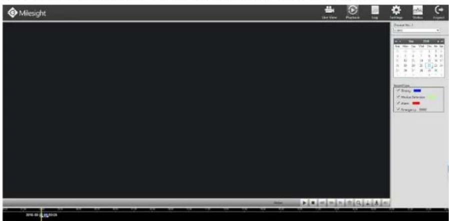
text_image
Milesight User Name Playback Log Set Page Views Options Show that: 1 Name: 2348 Size: 50 px Size: 2348 x 10 100% 100% 100% 100% 100% 100% 100% 100% 100% 100% 100% 100% 100% 100% 100% 100% 100% 100% 100% 100% 100% 100% 100% 100% 100% 100%F-4.3.2
Step2. Select Recorded files for Backup.
Select the channel and date you want to backup, then select the start time at time line and click
∞, it will change into which means cut begins.

text_image
2015-07-09 17:26:48 Emergency Timing MotionSelect the end time at time line and click , it will change into which means cut ends.

text_image
2015-07-25 17:26:39Then backup files can be found the files path set before.
Step3. Backup the files
Click the button and choose the path to save the file

text_image
2018-03-19 00:30:22 Emergency Timing Motion Detection Alarm4.3.3 Picture Files Backup
Step1. Enter record files path settings interface by clicking Settings→Local Configuration Choose Playback Picture Path.
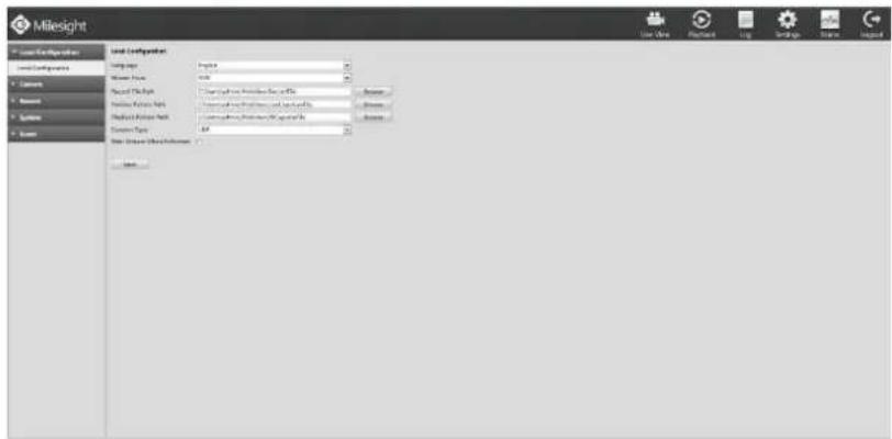
text_image
Milesight Local Configuration Location Name Address Report Date Report Date: 01/03/2024 Report Date: 01/03/2024 System Type: System Type: 01/03/2024 System Type: 01/03/2024 System Type: 01/03/2024 System Type: 01/03/2024 System Type: 01/03/2024 System Type: 01/03/2024 System Type: 01/03/2024 System Type: 01/03-2024 System Type: 01/03-2024 System Type: 01/03-2024 System Type: 01/03-2024 System Type: 01/03-2024 System Type: 01/03-2024 System Type: 01/03-2024 System Type: 16.7.1.1.1.1.1.1.1.1.1.1.1.1.1.1.1.1.1.1.1.1.1.1.1.1.1.1.1.1.1.1.1.1.1.1.1.1.1.1.1.1.1.1.1.1.1.1.1.1.1.1.F-4.3.3
Step2. Pause first when you want backup a special scene during video playback.
Step3. Click to save picture. Then backup picture can be found the files path set before.
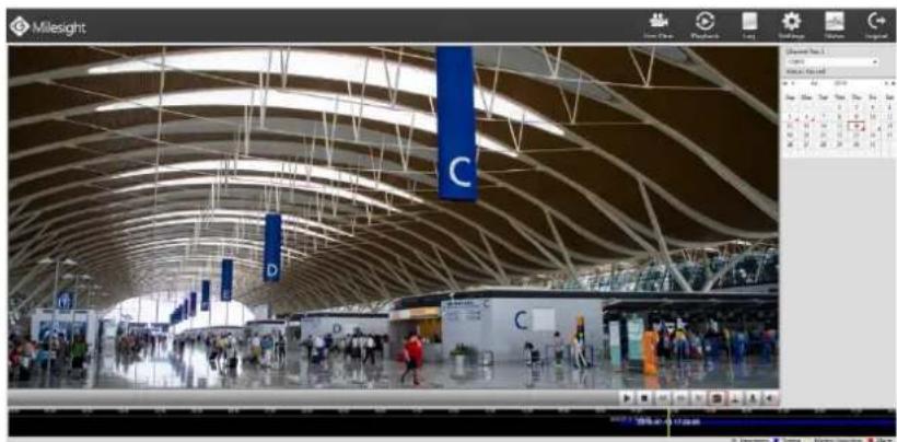
natural_image
Interior view of a modern airport terminal with curved roof and blue hanging banners (no visible text or symbols)F-4.3.4
4.4 Log
Select special period and type logs by Search tools. You can save the logs locally if it is necessary.
Step: Enter Log menu by clicking logMain Type→Sub Type→Start Time→End Time→Search→Save
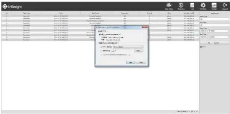
text_image
Milesight No Type Name Use Type Parameters Close View Save As/Out Add Type Add Type Add Type Add Type Add Type Add Type Add Type Add Type Add Type Add Type Add Type Add Type Add Type Add Type Add Type Add Type Add Type Add Type Add Type Add Type Add Type Add Type Add Type Add Type Add Type Add Type Add Type Add Type Add Type Add Type Add Type Add Type Add Type Add TypeF-4.4.1
4.5 Settings
4.5.1 Local Configuration
Step1. Enter Local Configuration interface by clicking Settings→Local Configuration.
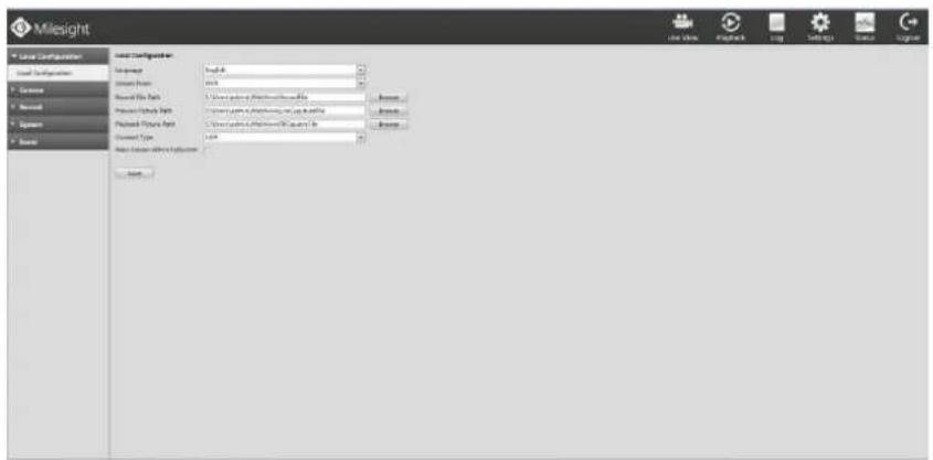
text_image
Milesight Local Configuration Local Configuration Access Report Report Data Report History Type Report History Type Document Type Report History Type Sub- configurations Sub- configurations Sub- configurations Sub- configurations Sub- configurations Sub- configurations Sub- configurations Sub- configurations Sub- configurations Sub- configurations Sub- configurations Sub- configurations Sub- configurations Sub- configurations Sub- configurations Sub- configurations Sub- configurations Sub- configurations Sub- configurations Sub- configurations Sub- configurations Sub- configurations Sub- configurations Sub- configurations Sub- configurations Sub- combinations Sub- combinations Sub- combinations Sub- combinations Sub- combinations Sub- combinations Sub- combinations Sub- combinations Sub- combinations Sub- combinations Sub- combinations Sub- combinations Sub- combinations Sub- combinations Sub- combinations Sub- combinations Sub- combinations Sub- combinations Sub- combinations Sub- combinations Sub- combinations Sub- combinations Sub- combinations Sub- combinations Sub- combinations Sub- configurationsF-4.5.1
Step2. Choose Languages.
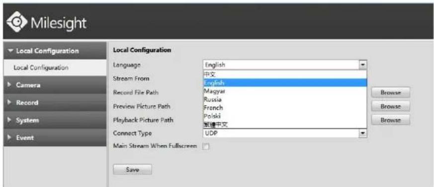
text_image
Milesight Local Configuration Language English Stream From 中文 Record File Path Magyar Preview Picture Path Russia Playback Picture Path French Connect Type ###中文 Main Stream When Fullscreen Save Browse Browse BrowseF-4.5.2
Step3. Set paths then save configurations.
4.5.2 Camera
Before configuration, please ensure that the IP device is connected to the same network as your NVR and that the network setting for your NVR is properly setup.
4.5.2.1 Camera Management
Step1. Enter Local Configuration interface by clicking SettingCamera.
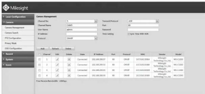
text_image
Milesight Local Configuration Camera Camera Management Camera Search FIZ Configuration Privacy Mask OSB Configuration Record System Event Camera Management Channel No: 5 Channel Name: CAMS User Name: admin IP Address: Protocol: ONVF Acid Retrench Delete Channel Edit Delete State IP Address Port Protocol MAC Vendor Model 1 ✓ ✗ Connected 192.168.200.57 BO ONVF 1CC1161308A Mislight Technology Co.,Ltd. MS-C1203 2 ✓ ✗ Connected 192.168.200.53 BO ONVF 1CC1161308A Mislight Technology Co.,Ltd. MS-C1203 3 ✓ ✗ Connected 192.168.200.59 BO ONVF 1CC1161308B Mislight Technology Co.,Ltd. MS-C1203 4 ✓ ✗ Connected 192.168.200.50 BO ONVF 1CC1161308B Mislight Technology Co.,Ltd. MS-C1203 Free Resource Bandwidth: 22MbpsF-4.5.3
Step2. Add IP Channel.
Method1. Add IP Channel in camera search interface
- Enter camera search interface by clicking Settingcamera→Camera Search.
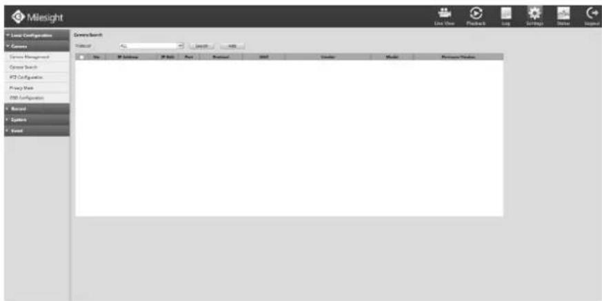
text_image
Milesight Logic Configuration Camera System Management Speed Search F2 Cngrations Proxy View USB Configuration Record System Word GeometrySearch historic View Search Add Top 3D Software 3D Tools Host Protocol Add Provider Media Software Provider Live View Pushback Log Settings Name InputF-4.5.4
- Click [Search] button to quickly search the IP devices that support ONVIF at the same network segment with NVR.
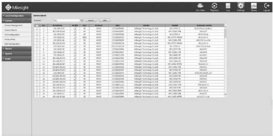
text_image
Milesight Local Configuration Camera Search Camera Current Management Camera Search 1 2 3 4 5 6 7 8 9 10 11 12 13 14 15 16 17 18 19 20 21 22 23 24 25 26 27 28 29 30 31 32 33 34 35 36 37 38 39 40 41 42 43 44 45 46 47 48 49 50 51 52 53 54 55 56 57 58 59 60 61 62 63 64 65 66 67 68 69 70 71 72 73 74 75 76 77 78 79 80 81 82 83 84 85 86 87 88 89 90 91 92 93 94 95 96 97 98 99 100 101 102 103 104 105 106 107 108 109 110 111 112 113 114 115 116 117 118 119 120 121 122 123 124 125 126 127 128 129 130 131 132 133 134 135 136 137 138 139 140 141 142 143 144 145 146 147 148 149 150 151 152 153 154 155 156 157 158 159 160 161 162 163 164 165 166 167 168 169 170 171 172 173 174 175 176 177 178 179 180 181 182 183 184 185 186 187 188 189F-4.5.5
- Click the channel, click [Add] button, input password and click [OK] button to finish or click [Cancel] button to cancel.
- Or Check to bulk adding the IP cameras if they are with same password.
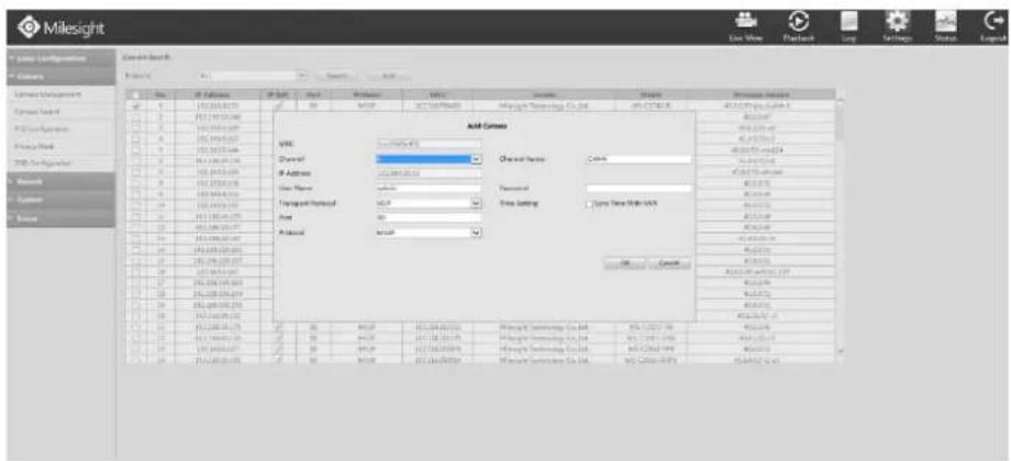
text_image
Milesight Add Cases VRR Channel P Address Transpnt Network Host P Address Add Cases Channel Name Cnsm Passwd Time setting Type Data With NAV OK Cancel Unconfirmed Information Add Cases Add Cases Add Cases Add Cases Add Cases Add Cases Add Cases Add Cases Add Cases Add Cases Add Cases Add Cases Add Cases Add Cases Add Cases Add Cases Add Cases Add Cases Add Cases Add Cases Add Cases Add Cases Add Cases Add Cases Add Cases Add Cases Add Cases Add Cases Add Cases Add Cases Add Cases Add Cases Add Cases Add CasesF-4.5.6
Method2. Add IP Channel in camera management interface
- Enter camera management menu by clicking SettingCamera→Camera Management
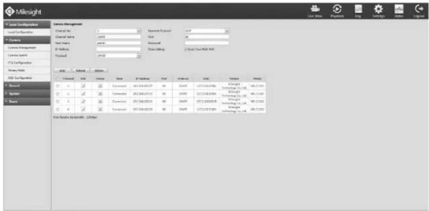
text_image
Milesight Local Configuration Local Exchange Current Current Management Current Settings PTC Configuration Primary Mode 2001 Configuration Channel Name: C:\Users\Program Files\ADD Channel type: C:\Users\Program Files\ADD Current Settings: Time Settings (3 Weeks) Time With Add Channel: Add Options Name: PTC Manager Address: 101-548-001-57 Contact: 101-548-001-52 Address: 101-548-001-50 Contact: 101-548-001-50 Address: 101-548-001-50 Address: 101-548-001-50 Address: 101-548-001-50 Address: 101-548-001-50 Address: 101-548-001-50 Address: 101-548,001-548 Address: 101-548,001-548 Address: 101-548,001-548 Address: 101-548,001-548 Address: 101-548,001-548 Address: 101-548,001-548 Address: 6/2/2023 Address: 6/2/2023 Address: 6/2/2023 Address: 6/2/2023 Address: 6/2/2023 Address: 6/2/2023 Address: 6/2/2023 Address: 6/2/2023 Address: 6/2/2023 Address: Not Available Subscribers, OptionsF-4.5.7
- Select idle channel then input complete information, click [Add] button.
There are three protocols available for camera connection:
- ONVIF: Add the camera with ONVIF protocol, you can add any IP cameras with ONVIF compatible if select this
protocol. The detail formats are shown in F-4.5.8;
- RTSP: Use RTSP to add camera. You can add any IP cameras which have RTSP protocol streams.
You need select 554 for the port and input the resource path for the camera. Take Milesight device as an example for main stream the resource path is "rtsp://IP:port/main" and the second stream is "rtsp://IP:port/sub". The details about adding format are shown in F-4.5.9;
- MSSP: If your IP camera is a Milesight device you can select this protocol to add cameras in the same LAN. The detail formats are shown in F-4.5.10;
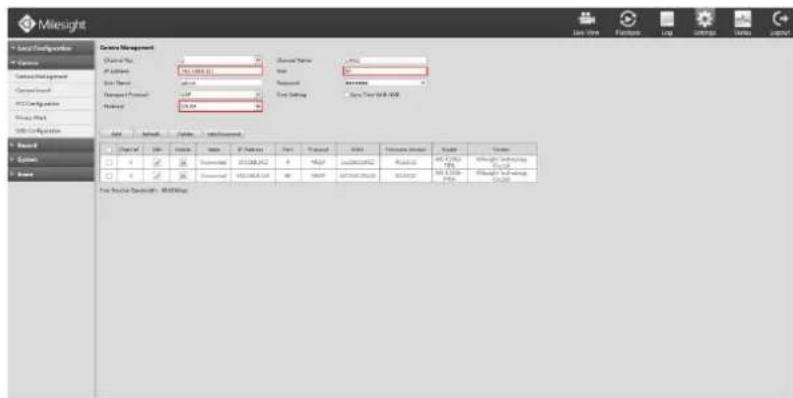
text_image
Milesight Local Configuration Categories Domain Management Comps Control Data Design Network Protocol Network Add Remove Delete Edit/Remove Name: 100.000.000 File Name: 100.000.000 Import Status: Normal Export Date: March 2018 Save Type: Web-100 File Edit View Insert File Edit View Insert File Edit View Insert File Edit View Insert File Edit View Insert File Edit View Insert File Edit View Insert File Edit View Insert File Edit View Insert File Edit View Insert File Edit View Insert File Edit View Insert File Edit View Insert File Edit View Insert File Edit View Insert File Edit View Insert File Edit View Insert File Edit View Insert File Edit View Insert File Edit View Insert File Edit View Inverter - WebWinPacF-4.5.8
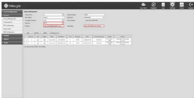
text_image
Milesight Service Management Customer Name: 0 Customer Type: admin Customer Address: 1234 Transport Description: LID Resource: 8150 Resource: http://www.milesight.com/ Service Management Address: https://www.milesight.com/ Service Management Accession Number: 100 Status: Status: Status: Status: Status Accession Number: 100 Status: Status: Status: Status: Status Accession Number: 100 Status: Status: Status: Status: Status Accession Number: 100 Status: Status: Status: Status: Status Accession Number: 100 Status: Status: Status: Status: Status Accession Number: 100 Status: Status: Status: Status: Status Accession Number: Accession Number: Accession Location: Accession Date: Accession Time: Accession Time: Accession Time: Accession Time: Accession Time: Accession Time: Accession Time: Accession Time: Accession Time: Accession Time: Accession Time: Accession Time: Accession Time: Accession Time: Accession Time: Accession Time: Accession Time: Accession Time: Accession Time: Accession Time: Accession Time: Accession Time: Accession Time: Accession Time: Accession Time: AccessionTime:F-4.5.9
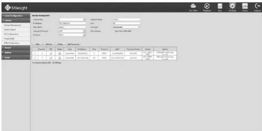
text_image
Milesight Local Configurations Citation Contact Management Contact Track FTP Configuration Project Web USB Configurations System System System System System System System System System System System System System System System System System System System System System System System System System System System System System System System System System System System System System System System System System System System System System System System System System System Total Service Backpage: $0.0000mmF-4.5.10
Step3. Check the connection status.
After adding the IP channels, click [Refresh] button, the [status] will show [connected] as below, If not, you need to check if the network is connected or whether the user name, password is correct or not.
| □ Channel Edit Delete State IP Address Port Protocol MAC Vendor Model | |||||||||
| □ 1 | Connected 192.168.200.55 | 80 | ONVIF | 1CC3161103DB | Milesight Technology Co.,Ltd. | MS-C3263 | |||
| □ 2 | Connected 192.168.200.53 | 80 | ONVIF | 1CC31611038A | Milesight Technology Co.,Ltd. | MS-C3263 | |||
| □ 3 | Connected 192.168.200.57 | 80 | ONVIF | 1CC3161103EA | Milesight Technology Co.,Ltd. | MS-C3263 | |||
| □ 4 | Connected 192.168.200.50 | 80 | ONVIF | 1CC316110369 | Milesight Technology Co.,Ltd. | MS-C3263 | |||
F-4.5.11
Step4. Configure IP Channel
After successfully adding the channel, click to re-edit the channel info, address, and password, etc.
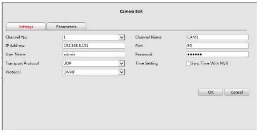
text_image
Camera Edit Settings Parameters Channel No. 1 ✓ Channel Name CAM1 IP Address 192.168.8.151 Port 80 User Name adults Password **** Transport Protocol UDP ✓ Time Setting ✓ Sync Time With NVR Protocol ONVIF OK CancelF-4.5.12
Select [Parameters] page to re-edit this channel parameters. Click [Save] to save the configuration
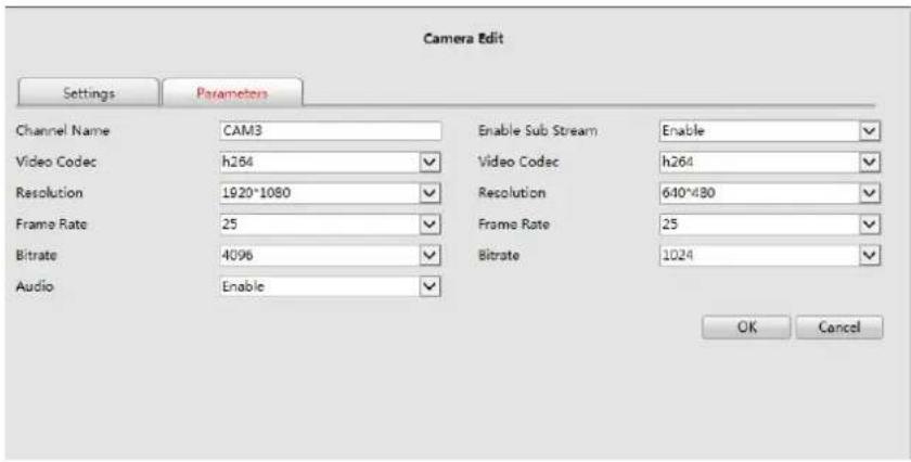
text_image
Camera Edit Settings Parameters Channel Name CAM3 Enable Sub Stream Enable Video Codec h264 Video Codec h264 Resolution 1920*1080 Resolution 640*480 Frame Rate 25 Frame Rate 25 Bitrate 4096 Bitrate 1024 Audio Enable OK CancelF-4.5.13
You can delete this channel by clicking, or you can select multiple devices and then click to delete.
| Channel | Edit | Delete | State | IP Address | Port | Protocol | MAC | Vendor | Model |
| 1 | ✓ | ✘ | Connected | 192.168.200.55 | 80 | ONVIF | 1CC3161103DB | Milesight Technology Co.,Ltd. | MS-C3263 |
| 2 | ✓ | ✘ | Connected | 192.168.200.53 | 80 | ONVIF | 1CC31611038A | Milesight Technology Co.,Ltd. | MS-C3263 |
| 3 | ✓ | ✘ | Connected | 192.168.200.57 | 80 | ONVIF | 1CC3161108EA | Milesight Technology Co.,Ltd. | MS-C3263 |
| 4 | ✓ | ✘ | Connected | 192.168.200.50 | 80 | ONVIF | 1CC316110369 | Milesight Technology Co.,Ltd. | MS-C3263 |
Note:
The user name and password entered here are the default user name and password. The management port is 80 and the default Transport protocol is UDP.
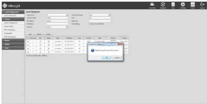
text_image
Milesight Search Management Channel No: 0 Search Name: 2.0001 File Name: 47-03 File Type: Normal Parameters: 0.0001 Source: Data & Web Name: Software Address: 123456898 Access: 123456898 Error: 0.0001 Error: 0.0001 Error: 0.0001 Error: 0.0001 Error: 0.0001 Error: 0.0001 Error: 0.0001 Error: 0.0001 Error: 0.0001 Error: 0.0001 Error: 0.000 Error: 0.0001 Error: 0.0001 Error: 0.0001 Error: 0.0001 Error: 0.0001 Error: 0.0001 Error: 0.0001 Error: 0.0001 Error: 0.0001 Error: 0.0002 Error: 0.0002 Error: 0.0002 Error: 0.0002 Error: 0.0002 Error: 0.0002 Error: 0.0002 Error: 0.0002 Error: 0.0002 Error: 0.0002 Error: 0.0003 Error: 0.0003 Error: 0.0003 Error: 0.0003 Error: 0.0003 Error: 0.0011 Error: 123456898 Error: 123456898 Error: 123456898 Error: 123456898 Error: 123456898 Error: 123456898 Error: 123456898 Error: 123456898 Error: 1234677777777777777777777777777777777777777777777777777777777777777777777777777777778 Error: 123456898 Error: 123456898 Error: 123456898 Error: 123456898 Error: 123456898 Error: 123456898 Error: 123456898 Error: 123512222222222222222222222222222222222222222222222222222222222222222222222222222222222222222222222F-4.5.14
4.5.2.2 Camera Search
Step1. Enter camera search interface by clicking Settings→Camera→Camera Search.
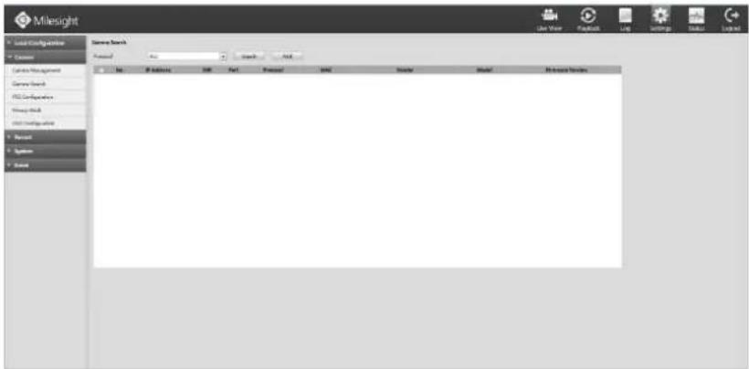
text_image
Milesight Local Configuration Current Current Management Current Search FSC Configuration Wisey Search Wisey Detection System System Server Rack Proposed: 100 Start: Add End: 36 IP address: 100 Port: 100 Performance: 100 Balance: 100 Model: 100 Data Source: 100F-4.5.15
Step2. Choose [All], then click [search] to quickly search the IP devices that support ONVIF at the same LAN with NVR; switch Protocol into [ONVIF] to search the IP devices that support ONVIF at the same network segment with NVR, or switch Protocol into [MILESIGHT] to search the IP devices that support MILESIGHT at the same LAN with NVR.
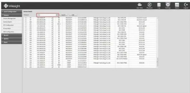
text_image
Milesight Local Configuration Service Bend Protocol: All Source: All Balance Balance Management Balance Search FTP Configuration Memory Map NCD Configuration Networks System System Bend Balance Balance Management Balance Search FTP Configuration Memory Map NCD Configuration Networks System System BendF-4.5.16
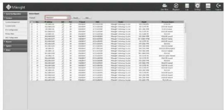
text_image
Mileught Special Parameters Technical Name: MILELIGHT Symbol: 10000000000000000000000000000000000000000000000000000000000000000000000000000000000000000000000000000 Current Parameters Current Location 12.1 12.2 12.3 12.4 12.5 12.6 12.7 12.8 12.9 13.0 13.1 13.2 13.3 13.4 13.5 13.6 13.7 13.8 13.9 14.0 14.1 14.2 14.3 14.4 14.5 14.6 14.7 14.8 14.9 15.0 15.1 15.2 15.3 15.4 15.5 15.6 15.7 15.8 15.9 16.0 16.1 16.2 16.3 16.4 16.5 16.6 16.7 16.8 16.9 17.0 17.1 17.2 17.3 17.4 17.5 17.6 17.7 17.8 17.9 18.0 18.1 18.2 18.3 18.4 18.5 18.6 18.7 18.8 18.9 19.0 19.1 19.2 19.3 19.4 19.5 19.6 19.7 19.8 19.9 20.0 20.1 20.2 20.3 20.4 20.5 20.6 20.7 20.8 20.9 21.0 21.1 21.2 21.3 21.4 21.5 21.6 21.7 21.8 21.9 22.0 22.1 22.2 22.3 22.4 22.5 22.6 22.7 22.8 22.9 23.0 23.1 23.2 23.3 23.4 23.5 23.6 23.7 23.8 23.9 24.0 24.1 24.2 24.3 24.4 24.5 24.6 24.7 24.8 24.9 25.0 25.1 25.2 25.3 25.4 25.5 25.6 25.7 25.8 25.9 26.0 26.1 26.2 26.3 26.4 26.5 26.6 26.7 26.8 26.9 27.0 27.1 27.2 27.3 27.4 27.5 27.6 27.7 27.8 27.9 28.0F-4.5.17
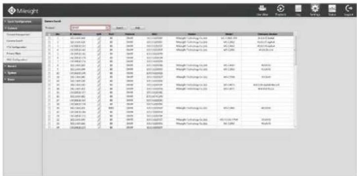
text_image
Mileight Sales Book Name: Milelight Sales Sales Customer Service 1. 0 2. 1 3. 2 4. 3 5. 4 6. 5 7. 6 8. 7 9. 8 10. 9 11. 10 12. 11 13. 12 14. 13 15. 14 16. 15 17. 16 18. 17 19. 18 20. 19 21. 20 22. 21 23. 22 24. 23 25. 24 26. 25 27. 26 28. 27 29. 28 30. 29 31. 30 32. 31 33. 32 34. 33 35. 34 36. 35 37. 36 38. 37 39. 38 40. 39 41. 40 42. 41 43. 42 44. 43 45. 44 46. 45 47. 46 48. 47 49. 48 50. 49 51. 50 52. 51 53. 52 54. 53 55. 54 56. 55 57. 56 58. 57 59. 58 60. 59 61. 60 62. 61 63. 62 64. 63 65. 64 66. 65 67. 66 68. 67 69. 68 70. 69 71. 70 72. 71 73. 72 74. 73 75. 74 76. 75 77. 76 78. 77 79. 78 80. 79 81. 80 82. 81 83. 82 84. 83 85. 84 86. 85 87. 86 88. 87 89. 88 90. 89 91. 90 92. 91 93. 92 94. 93 95. 94 96. 95 97. 96 98. 97 99. 98 100. 99F-4.5.18
Step3. Click the channel, click [Add] button, input password and click [OK] button to finish or click [Cancel] button to cancel, or Check to bulk adding the IP cameras if they are with same password.
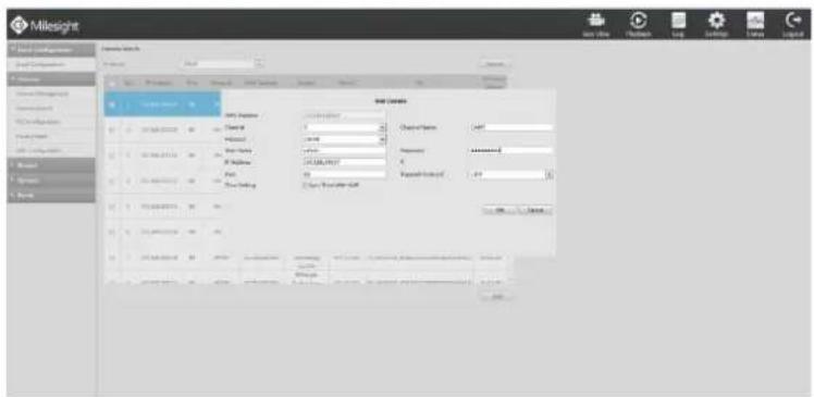
text_image
Milesight File Edit View Help Tools Help Settings Help Window Help Name: Milelight File Edit View Help Tools Help Tools Help Settings Help Tools Help Settings Help Tools Help Settings Help Tools Help Settings Help Tools Help Settings Help Tools Help Settings Help Tools Help Settings Help Tools Help Settings Help Tools Help Settings Help Tools Help Settings Help Tools Help Settings Help Tools Help Settings Help Tools Help Settings Help Tools Help Settings Help Tools Help Settings Help Tools Help Settings Help Tools Help Settings Help Tools Help Settings Help Tools Help Settings Help Tools Help Settings Help Tools Help Settings Help Tools Help Settings Help Tools Help Settings Help Tools Help Settings Help Tools Help Settings Help Tools Help Systems Help Systems Help Systems Help Systems Help Systems Help Systems Help Systems Help Systems Help Systems Help Systems Help Systems Help Systems Help Systems Help Systems Help Systems Help Systems Help Systems Help Systems Help Systems Help Systems Help Systems Help Systems Help Systems Help Systems Help Systems Help Systems Help Systems Help Systems Help Systems Help Systems Help Systems Help Systems Help Systems Help Systems Help Systems Help Systems Help Systems Help Systems Help Systems Help Systems Help Systems Help Systems Help Systems Help Systems Help Systems Help Systems Help Systems Help Systems Help Systems Help Systems Help System File Edit View Help Tools Help Tools Help Settings Help Tools Help Settings Help Tools Help Settings Help Tools Help Settings Help Tools Help Settings Help Tools Help Settings Help Tools Help Settings Help Tools Help Settings Help Tools Help Settings Help Tools Help Settings Help Tools Help Settings Help Tools Help Settings Help Tools Help Settings Help Tools Help Settings Help Tools Help Settings Help Tools Help Settings help Name: Milelight File Edit View Help Tools Name: Milelight File Edit View Help Tools Name: Milelight File Edit View Help Tools Name: Milelight File Edit View Help Tools Name: Milelight File Edit View Help Tools Name: Milelight File Edit View Help Tools Name: Milelight File Edit View Help Tools Name: Milelight File Edit View Help Tools Name: Milelight File Edit View Help Tools Name: Milelight File Edit View Help ToolsF-4.5.19
4.5.2.3 PTZ Configuration
Step: Enter configuration interface by clicking SettingCamera→PTZ Configuration
Select a channel and set the PTZ parameters. You can click [Copy] to copy the same configuration to other channels.
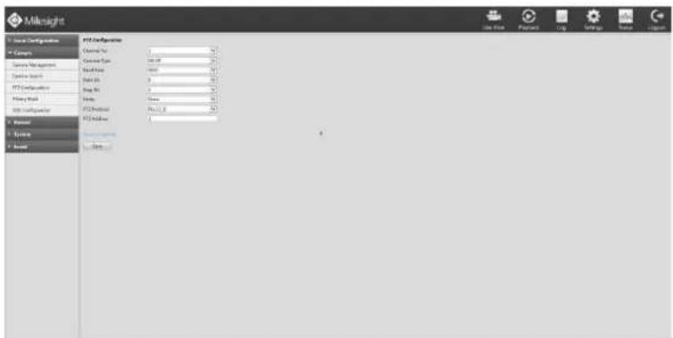
text_image
Milklight Local Configuration Camera Service Management Center System FTP Components Map No History Book FTP Component FTP Document System Balance FTP Components File Path Use Time Payment Log Settings System LoganF-4.5.20
Note:
- The PTZ protocol and address of IP channel must be consistent with those of the PTZ decoder.
- Settings for a PTZ camera must be configured before it can be used. Make sure that the PTZ and RS-485 of the NVR are connected properly.
4.5.2.4 Privacy Mask
Milesight NVR support privacy mask. It is used to cover some privacy area which is not proper to appear on monitor.
You can add a privacy mask by following steps:
Step1. Enter configuration interface by clicking SettingCamera→Privacy Mask.
Step2. Select channel and switch to [enable] option.
Step3. Enter numbers or draw areas to set the area to cover.
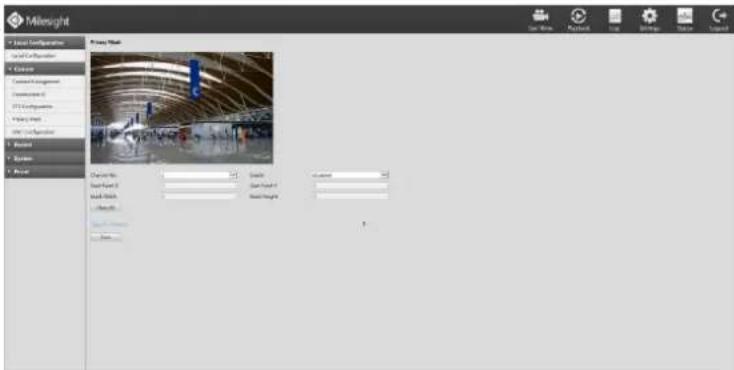
text_image
Milesight Primary Mask File Edit View Insert Tools Help Add Share Configuration Local Configuration Access Customs Installation Construction ID FX100000000000000000000000000000000000000000000000000000000000000000000000000000000 Share Name: Share Type: Share Length: Share Height: Share Width: Share Color: Share Bottom:F-4.5.21
Step4. You can click [Copy] to copy the same configuration to other channels.

text_image
Milesight Local Configuration Local Settings Categories Carry Management Carry Index FIR Communications Power Grid File Properties Transport System Balance Balance Balance Balance Balance Balance Balance Balance Balance Balance Balance Balance Balance Balance Balance Balance Balance Balance Balance Balance Balance Balance Balance Balance Balance Balance Balance Balance Balance Balance Balance Balance Balance Balance Balance Balance Balance Balance Balance Balance Balance Balance Balance Balance Balance Balance Balance Balance Balance Balance Baseline Data 100% New Date: 2023-04-26 10:00:00:00 15:00:00:00 17:00:00:00 18:00:00:00 19:00:00:00 20:00:00:00 21:00:00:00 22:00:00:00 23:00:00:00 24:00:00:00 25:00:00:00 26:00:00:00 27:00:00:00 28:00:00:00 29:00:00:00 30:00:00:00 31:00:00:00 32:00:00:00 33:00:00:00 34:00:00:00 35:00:00:00 36:00:00:00 37:00:00:00 38:00:00:00 39:00:00:00 40:00:00:00 41:00:00:00 42:00:00:00 43:00:00:00 44:00:00:00 45:00:00:00 46:00:00:00 47:00:00:00 48:00:00:00 49:00:00:00 50:00:00:00 51:00:00:00 52:00:00:00 53:00:00:0F-4.5.22
Step5. Select "Save" to save the settings.
Note:
[Start Point X] and [Start Point Y] decide the point of the area starts, [Mask Width] and [Mask Height] decide the size of the area.
4.5.2.5 OSD Configuration
You can set OSD (On Screen Display) on NVR, and the OSD will be synchronized on IPC. Entering OSD Configuration interface by clicking: SettingCamera→OSD Configuration.
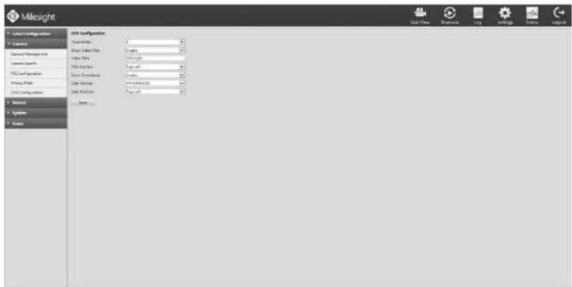
text_image
Milesight Local Configuration Category Serving Management General Services FCA Configuration Key Points FCA Configuration Named Systems Notes USB Configuration Format Data Format Data Map Video Map Video Map View Structure View Frame View Position View Date Data Files Data Files Data Files Data Files Data Files Data Files Data Files Data Files Data Files Data Files Data Files Data Files Data Files Data Files Data Files Data Files Data Files Data Files Data Files Data Files Data Files Data Files Data Files Data Files Data Files Data Files Data Files Data Files Data Files Data Files Data Files Data Files Data Files Data FilesF-4.5.23
Select channel and finish the info and save.
[Video Title]: Set the video title for the channel;
[Title Position]: Set the position for the video title: Top-Left or Top-Right;
[Date Position]: Set the position for the date: Top-Left, Top-Right, Bottom-Left or Bottom-Right;
[Date Format]: Set format for date: YYYY-MM-DD, MM/DD/YY or DD/MM/YYYY.
4.5.3 Record
Preparation for Configuration
Step1. Ensure your NVR has Install and initialize the HDD.
Enter disk management interface by clicking Setting System→Disk Management
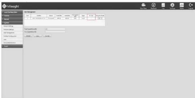
text_image
Milesight Local Settings Customs Network Systems System Settings Network Settings System Management Package Configuration user System Maintenance Local Data Management Date Status Total Date Total Date System Date Type In line Regular Data 128.74 Total Settings For Cash/Note: Default CancelF-4.5.24
Step2. Ensure that HDD has sufficient storage space.
Enter disk management interface by clicking Settings System → Disk Management. Select [Recycle Mode] to "ON" in the case of insufficient capacity of HDD.
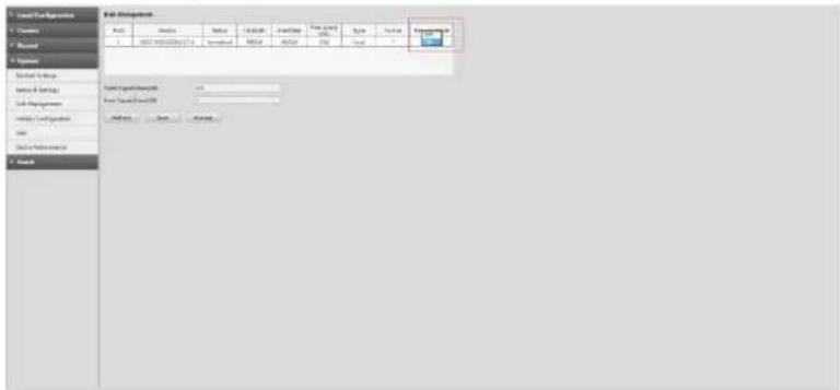
text_image
Local Configurations File Environment File Name File Name File Type File Size Size Value Parameters 1. 2000 M30000000000 2. 500000000000 3. 100000000000 4. 150000000000 5. 200000000000 6. 250000000000 7. 300000000000 8. 350000000000 9. 40000000000 10. 4500000000 11. 500000000 12. 55000000 13. 60000 14. 6500 15. 700 16. 750 17. 800 18. 850 19. 900 20. 950 21. 100 22. 115 23. 135 24. 155 25. 175 26. 195 27. 215 28. 235 29. 255 30. 275 31. 305 32. 325 33. 335 34. 335 35. 335 36. 335 37. 335 38. 335 39. 335 40. 335 41. 335 42. 335 43. 335 44. 335 45. 335 46. 335 47. 335 48. 335 49. 335 50. 335 51. 335 52. 335 53. 335 54. 335 55. 335 56. 335 57. 335 58. 335 59. 335 60. 335 61. 335 62. 335 63. 335 64. 335 65. 335 66. 335 67. 335 68. 335 69. 335 70. 335 71. 335 72. 335 73. 335 74. 335 75. 335 76. 335 77. 335 78. 335 79. 335 80. 335 81. 335 82. 335 83. 335 84. 335 85. 335 86. 335 87. 335 88. 335 89. 335 90. 335 91. 335 92. 335 93. 335 94. 335 95. 335 96. 335 97. 335 98. 335 99. 335F-4.5.25
4.5.3.1 Record Mode
Step1. Enter record mode menu by clicking Settings→Record→Record Mode.
There are three record modes: No Recording/Always Record/Record by Schedule. You can select the desired one for every channel.
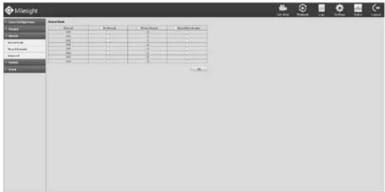
text_image
Milesight Market Stock Name: Milesight Stocks Price Market Value Market Price Market Price Market Value Market Value Market Value Market Value Market Value Market Value Market Value Market Value Market Value Market Value Market Value Market Value Market Value Market Value Market Value Market Value Market Value Market Value Market Value Market Value Market Value Market Value Market Value Market Value Market Value Market Value Market Value Market Value Market Value Market Value Market Value Market Value Market Value Market ValueF-4.5.26
[No Record]: NVR will not record if you choose this column;
[Always Record]: It will always record the chosen channel;
[Record By Schedule]: If you want NVR to record by schedule, then you need select this column and then go to 4.5.3.2;
Step2. Click [OK] to save the configuration.
4.5.3.2 Record Schedule
Note:
The days are divided as Holiday/Sunday/Monday/Tuesday/Wednesday/Thursday/Friday/Saturday. The schedule of Holiday is superior to other days. To set the holiday information, go to Chapter 4.5.4.4
Method1. General Setting
Step1. Enter Record schedule interface by clicking Record SettingRecord Schedule.
Step2. Select the desired channel (e.g. Channel 1).
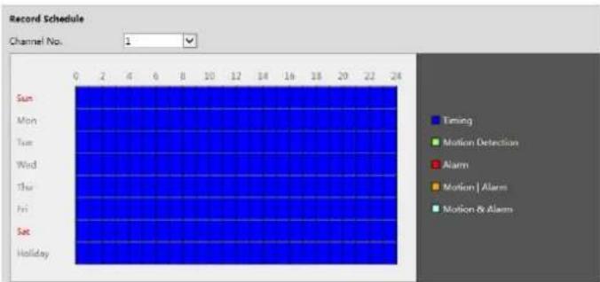
text_image
Record Schedule Channel No. 1 Sun Mon Tue Wed Thu Fri Sat Holiday 0 2 4 6 8 10 12 14 16 18 20 22 24 Timing Motion Detection Alarm Motion | Alarms Motion & AlarmsF-4.5.27
Step3. Set record schedule.
Select a day from the drop-down list of [Day], click to set a period, up to 12 periods can be set. (e.g.01:00 to 05:00 for none recording; 06:00 to 18:00 for timing recording; 19:00 to 21:00 for Motion recording; 22:00 to 24:00 for Alarm recording)
| Sun | Mon | Tue | Wed | Thu | Fri | Sat | Holiday |
| Period | Start Time | End Time | Record Type | ||||
| 1 | 00:00 | 24:00 | Timing | ||||
| 2 | 00:00 | 00:00 | Timing | ||||
| 3 | 00:00 | 00:00 | Timing | ||||
| 4 | 00:00 | 00:00 | Timing | ||||
| 5 | 00:00 | 00:00 | Timing | ||||
| 6 | 00:00 | 00:00 | Timing | ||||
| 7 | 00:00 | 00:00 | Timing | ||||
| 8 | 00:00 | 00:00 | Timing | ||||
| 9 | 00:00 | 00:00 | Timing | ||||
| 10 | 00:00 | 00:00 | Timing | ||||
| 11 | 00:00 | 00:00 | Timing | ||||
| 12 | 00:00 | 00:00 | Timing | ||||
| □ Select All | |||||||
| □ Sun □ Mon □ Tue □ Wed □ Thu □ Fri □ Sat □ Holiday | |||||||
F-4.5.28
| Sun Mon Tue Wed Thu Fri Sat Holiday | ||||||
| Period Start Time End Time Record Type | ||||||
| 1 00:00 24:00 Timing Motion Detection Alarm Motion | Alarm Motion & Alarm Timing | ||||||
| 4 00:00 Timing | ||||||
| 5 00:00 Motion Detection Alarm Motion | Alarm Motion & Alarm Timing | ||||||
| 6 00:00 00:00 Timing | ||||||
| 7 00:00 00:00 Timing | ||||||
| 8 00:00 00:00 Timing | ||||||
| 9 00:00 00:00 Timing | ||||||
| 10 00:00 00:00 Timing | ||||||
| 11 00:00 00:00 Timing | ||||||
| 12 00:00 00:00 Timing | ||||||
| □ Select All | ||||||
| □ Sun Mon Tue Wed Thu Fri Sat Holiday Copy to Week |
F-4.5.29
Click and check to copy to other channels.
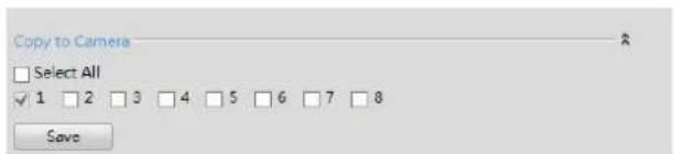
text_image
Copy to Camera □ Select All ✓ 1 □ 2 □ 3 □ 4 □ 5 □ 6 □ 7 □ 8 Save4.5.3.3 Advanced
Select the desired channel and set record time personally, Click and check to copy to other channels.
text_image
Milesight Local Configuration Access Carbon Monograph Carbon Search FCC Configuration Security Mode USB Configuration Access Resource Map Resource Map Bar Advanced System SystemF-4.5.30
Illustration for Parameters
[Channel Selection]: Select the channel which will be set.
[Post Record]: Enable/Disable post record after the event is over
[Duration Time]: Event post-record duration before event alarm
[Audio Record]: Select to record audio or not
[Record Stream Type]: Select Main stream or sub stream for record
Lastly, you can choose the copy button to copy the settings of record to other channels.
[Due Time]: Set the due time of recording files.
4.5.4 System
4.5.4.1 General Settings
Step: Enter general menu by clicking SettingSystem→General
To setup the general parameters of NVR, including modify the host name, device ID, select resolution, and set system time manually, etc.
text_image
Milesight Local Configuration General Settings Settings View Server Tools 10.5 Server Tools 10 New Portion New Portion 10.5 System Server Tools Server Tools Active System Server Tools Server Tools Data Management File Configuration Load Server Protection BuildF-4.5.31
4.5.4.2 Network Settings
4.5.4.2.1 Basic Configuration
Step: Enter the network setting menu to set the network parameters by clicking Settings → System → Network Settings, select "Basic" page
Basic configuration includes working mode, IP address, subnet mask, gateway, MTU, DNS server, etc.
text_image
Milesight Network settings Name: Milesight Type: All Size: 100 Address: Milesight Network Settings: Milesight Network Settings: Milesight Network Management: Milesight Network Configuration: Milesight Data: Milesight Network Network: Milesight Network Network: Milesight Network Network: Milesight Network Network: Milesight Network Network: Milesight Network Network: Milesight Network Network: Milesight Network Network: Milesight Network Network: Milesight Network Network: Milesight Network Network: Milesight Network Network: Milesight Network Network: Milesight Network Network: Milesight Network Network: NLSN Network Network: NLSN Network Network: NLSN Network Network: NLSN Network Network: NLSN Network Network: NLSN Network Network: NLSN Network Network: NLSN Network Network: NLSN Network Network: NLSN Network Network: NLSN Network Network: NLSN Network Network: NLSN Network Network: NLSN Network Network: NLSN Internet Security: Internet Security: Internet Security: Internet Security: Internet Security: Internet Security: Internet Security: Internet Security: Internet Security: Internet Security: Internet Security: Internet Security: Internet Security: Internet Security: Internet Security: Internet Security: Internet Security: Internet Security: Internet Security: Internet Security: Internet Security: Internet Security: Internet Security: Internet Security: Internet Security: Internet Security: Internet Security: Internet Security: Internet Security: Internet Security: Internet Security: Internet Security: Internet Security: Internet Security: International Security: International Security: International Security: International Security: International Security: International Security: International Security: International Security: International Security: International Security: International Security: International Security: International Security: International Security: International Security: International Security: International Security: International Security: International Security: International Security: International Security: International Security: International Security: International Security: International Security: International Security: International Security: International Security: International Security: International Security: International Security: International Security: International Security: International security : International security : International security : International security : International security : International security : International security : International security : International security : International security : International security : International security : International security : International security : International security : International security : International security : International security : International security : International security : International security : International security : International security : International security : International security : International security : International security : International security : International security : International security : International security : International security : International security : International security : International security : International security : International security : International security : International security : International security : International security : International security : International security : International security : International security : International security : International security : International security : International security : International security : International security : International security : International security : International security : International security : International security : International security : International security : International security : International security : International security : International security : International security : International security : International security : International security : International security : International securiters : Milesight Milesight : Milesight Milesight : Milesight Milesight : Milesight Milesight : Milesight Milesight : Milesight Milesight : Milesight Milesight : Milesight Milesight : Milesight Milesight : Milesight Milesight : Milesight Milesight : Milesight Milesight : Milesight Milesight : Mileslight Mileslight : Mileslight Mileslight : Mileslight Mileslight : Mileslight Mileslight : Mileslight Mileslight : Mileslight Mileslight : Mileslight Mileslight : Mileslight Mileslight : Maleslight Maleslight : Maleslight Maleslight : Maleslight Maleslight : Maleslight Maleslight : Maleslight Maleslight : Maleslight Maleslight : Maleslight Maleslight : Maleslight Maleslight : Maleslight Maleslight : Maleslight Maleslight : Maleslight Maleslight : Maleslight Maleslight : Maleslight Maleslight : MulesllnlllllllllllllllllllllllllllllllllllllllllllllllllllllllllllllllllllllllllllllllllllllllllllllllllllllllllllllllllllllllllllllllllllllllllllllllllllllllllllllllllllllllllllllllllllF-4.5.32
Note:
- Check the DHCP check-box if there has a DHCP server running in networks.
- The valid range of MTU is 500\~9676.
- Do not input an IP address conflict with another device.
4.5.4.2.2 PPPoE
Step: Enter PPPOE menu by clicking SettingSystem→Network Settings. Select "PPPoE" page
Check the PPPoE check-box to enable the feature, and then input user name, password and confirm password for PPPoE access.
text_image
Milesight Store Setup Store Name: Store Location: Store Type: Store Name: Store Location: Store Type: Store Name: Store Name: Store Name: Store Name: Store Name: Store Name: Store Name: Store Name: Store Name: Store Name: Store Name: Store Name: Store Name: Store Name: Store Name: Store Name: Store Name: Store Name: Store Name: Store Name: Store Name: Store Name: Store Name: Store Name: Store Name: Store Name: Store Name: Store Name: Store Name: Store Name: Store Name: Store Name: Store Name: Store Name:F-4.5.33
Note:
- User name and password of PPPoE can be obtained from your service provider. Once the setup is
completed, a connected status will be shown.
- PPPoE function is not available for 4K/H.265 series NVR.
4.5.4.2.3 DDNS
Step: Enter DDNS configuration menu by clicking SettingSystem→Network, Select "DDNS" page
If your NVR is setup to use PPPoE to connect public network, you may need to use DDNS (Dynamic Domain Name System) to solve the problems from dynamic IP address. Check the DDNS check-box to enable the feature. Select "DDNS Server", and input user name, password and host name, and then confirm. Click [Save] for application.
Note:
"Host Name" can use letters, figures and hyphen (-), and must begin with letters.
text_image
Milesight Local Configurations C:\Users\Settings Report Report System Settings System Settings Data Management History Configuration Add Remove Maintenance Insert system settings None Default Use Table Application Use Table Protocol Use Table Data Manager Data Manager None... Save Settings Save Settings Save Settings Save Settings Save Settings Save Settings Save Settings Save Settings Save Settings Save Settings Save Settings Save Settings Save Settings Save Settings Save Settings Save Settings Save Settings Save Settings Save Settings Save Settings Save Settings Save Settings Save Settings Save Settings Save Settings Save Settings Save Settings Save Settings Save Settings Save Settings Save Settings Save Settings Save Settings Save Settings Solve Settings Solve Settings Solve Settings Solve Settings Solve Settings Solve Settings Solve Settings Solve Settings Solve Settings Solve Settings Solve Settings Solve Settings Solve Settings Solve Settings Solve Settings Solve Settings Solve Settings Solve Settings Solve Settings Solve Settings Solve Settings Solve Settings Solve Settings Solve Settings Solve Settings Srove Settings Srove Settings Srove Settings Srove Settings Srove Settings Srove Settings Srove Settings Srove Settings Srove Settings Srove Settings Srove Settings Srove Settings Srove Settings Srove Settings Srove Settings Srove Settings Srove Settings Srove Settings Srove Settings Srove Settings Srove Settings Srove Settings Srove Settings Srove Settings Srove Settings Slive Settings Slive Settings Slive Settings Slive Settings Slive Settings Slive Settings Slive Settings Slive Settings Slive Settings Slive Settings Slive Settings Slive Settings Slive Settings Slive Settings Slive Settings Slive Settings Slive Settings Slive Settings Slive Settings Slive Settings Slive Settings Slive Settings Slive Settings Slive Settings Slive Settings S live settingsF-4.5.34
4.5.4.2.4 Email
Step: Enter Mail configuration page by clicking Setting→System→Network→Email
Set the Sender E-mail Address, User Name, Password, and SMTP Server:
text_image
Milesight Local Configurations Camera Camera Management Camera Stock FTP Configuration Wire Work FTP Configuration Hardware Stream Filter Record Settings Advanced Options Serial Settings Network Settings Data Parameters Accessibility Configuration User Service Maintenance Server Server Name: http://4018.123.com Password: 999999 SMTP Server: http://111.com SMTP Link: 0 Connection: Web: 100 Add Number: 10000000000000000000000000000000000000000000000000000000000000000000000000000000000000000000000000000 Server: http://4018.123.com Switch: http://4018.123.com Accession: http://4018.123.com Protocol: http://4018.123.com System: http://4018.123.comF-4.5.35
[User name]: The E-mail address you choose to send emails.
[Password]: The password of the E-mail.
[SMTP Server]: The SMTP Server of your E-mail.
[SMTP Port]: The port of SMTP Server, it's usually 25.
[Encryption]: Security Protocol of email sending, includes TLS and SSL.
[Sender Name]: Named by yourself for the Sender E-mail.
[Sender Address]: It must be same with [User name].
[Select Receiver]: You can have 3 receivers once.
[Receiver]: Named by yourself for the Receiver E-mail.
[Receiver Address]: E-mail Address for the receivers.
[Host Name]: For attaching URL when sending emails.
Select [Test] to check if the Mail function is workable
text_image
The page at 192.168.8.179 says: Email send successfully. OKNote:
- You will get a screenshot every time for motion detection email sending.
- If you use a port forward IP of NVR for the Host Name, please type the entire address including the port.
- If click the URL in the alarm emails within 10 minutes, you can visit NVR Web GUI without login.
4.5.4.2.5 P2P
You can use M-VMS to watch the remote live view by P2P. With the introduction of P2P, you can watch the NVR Live view from WAN without do any port forwarding on the router. Click System→Network→P2P, you will see the image like below.
text_image
Milebright Network Settings 1. System: 2000 2. System: 2000 3. System: 2000 4. System: 2000 5. System: 2000 6. System: 2000 7. System: 2000 8. System: 2000 9. System: 2000 10. System: 2000 11. System: 2000 12. System: 2000 13. System: 2000 14. System: 2000 15. System: 2000 16. System: 2000 17. System: 2000 18. System: 2000 19. System: 2000 20. System: 2000 21. System: 2000 22. System: 2000 23. System: 2000 24. System: 2000 25. System: 2000 26. System: 2000 27. System: 2000 28. System: 2000 29. System: 2000 30. System: 2000 31. System: 2000 32. System: 2000 33. System: 2000 34. System: 2000 35. System: 2000 36. System: 2000 37. System: 2000 38. System: 2000 39. System: 2000 40. System: 2000 41. System: 2000 42. System: 2000 43. System: 2000 44. System: 2000 45. System: 2000 46. System: 2000 47. System: 2000 48. System: 2000 49. System: 2000 50. System: 2000 51. System: 2000 52. System: 2000 53. System: 2000 54. System: 2000 55. System: 2000 56. System: 2000 57. System: 2000 58. System: 2000 59. System: 2000 60. System: 2000 61. System: 2000 62. System: 2000 63. System: 2000 64. System: 2000 65. System: 2000 66. System: 2000 67. System: 2000 68. System: 2000 69. System: 2000 70. System: 2000 71. System: 2000 72. System: 2000 73. System: 2000 74. System: 2000 75. System: 2000 76. System: 2000 77. System: 2000 78. System: 2000 79. System: 2000 80. System: 200F-4.5.36
- Choose "Enable" from the drop-down list of "P2P";
- Fill in your Company Name or your Individual Name in the "Company Name";
- Fill in your Email address in the "Email" for active;
- Save the settings.
Note:
Activation works as soon as email sends successfully. It is no need to contact Milesight to activate again.
4.5.4.2.6 More
Step: Enter More configuration page by clicking Setting→System→Network Settings→More
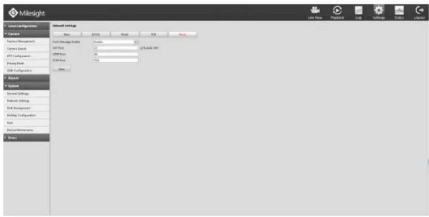
text_image
Milesight Local Configuration Connect Device Management Camera Search FTP Configuration Proxy Pack USB Configuration Baseset System Server Settings Network Settings Risk Management Auto-Configuration User Bus/Continuous Brand Link Name: 1230000000000000000000000000000000000000000000000000000000000000000000000000000000000000000000000000000 Network Settings Wireless Full-Message Details USB Pack USB Pack USB Pack USB Pack USB Pack USB Pack USB Pack USB Pack USB Pack USB Pack USB Pack USB Pack USB Pack USB Pack USB Pack USB Pack USB Pack USB Pack USB Pack USB Pack USB Pack USB Pack USB Pack USB Pack USB Pack USB Pack USB Pack USB Pack USB Pack USB Pack USB Pack USB Pack USB Pack USB PackF-4.5.37
Push Message Enable
With this option enabled, you can receive the alarm message on the mobile application(M-VMS).
SSH Port Setting
Secure Shell (SSH) has many functions; it can replace Telnet, and also provides a secure channel for FTP, POP, even for PPP.
Note:
The default SSH port is 22.
HTTP Port Setting
The default HTTP port is 80. Please modify HTTP ports according to actual application.
Note:
-
The default HTTP port for IE browser is 80.
-
HTTP port is used for remote network access.
RTSP Port Setting
Real Time Streaming Protocol (RTSP) is an application layer protocol in TCP/IP protocol system. The default RTSP port is 554. Please modify RTSP port according to actual application.
Note:
- RTSP port is used for remote network live view.
- RTSP port valid range is 554 or 1024\~65535.
Service Port Setting
Service port is used to remote access when add NVR by mobile device.
The default Service port is 1100. Please modify Service port according to actual application.
Note:
- This option is not available for 4K/H.265 series NVR.
- You can add this port when using P2P/port mapping/LAN IP to add NVR, 4K/H.265 series NVR use port 80 to add.
- When port mapping, you still need to map 554 to 554. Only then you can use 1100 to watch the live view by remote WAN.
4.5.4.3 Disk Management
Step: Enter disk configuration menu by clicking SettingSystem→Disk Management
Configuration page contains the basic information of the disk, see F-4.5.38. Select a disk and click [Format] to format the disk.
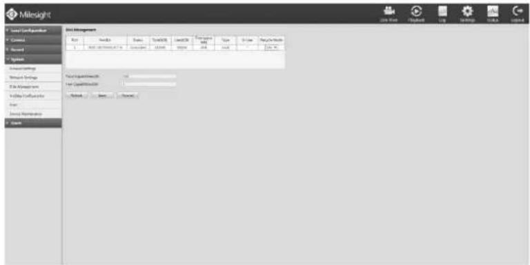
text_image
Milesight Event Management Event Status Status Status Status Status Status Status Status Status Status Status Status Status Status Status Status Status Status Status Status Status Status Status Status Status Status Status Status Status Status Status Status Status Status Status Status Status Status Status Status Status Status Status Status Status Status Status Status Status Status Positive Positive Positive Positive Positive Positive Positive Positive Positive Positive Positive Positive Positive Positive Positive Positive Positive Positive Positive Positive Positive Positive Positive Positive Positive Positive Positive Positive Positive Positive Positive Positive Positive Positive Positive Positive Positive Positive Positive Positive Positive Positive Positive Positive Positive Positive Positive Positive Positive Positive NegativeF-4.5.38
4.5.4.4 Holiday Configuration
It can configure the record or image capture schedule for holidays of the current year. Step1. Enter holiday setting menu by clicking Setting→System→Holiday Configuration.
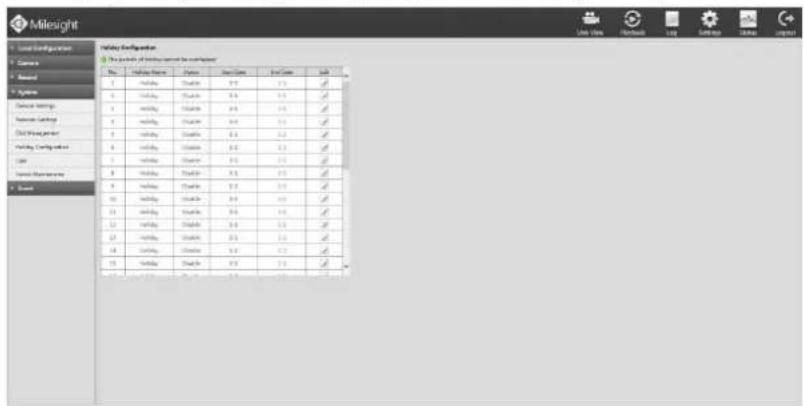
text_image
Milesight Holiday Configuration This product is a combination between the holiday? Date: Holiday Date Time: New Date End Date Start Date 1 Holiday 2 3 4 5 6 7 8 9 10 11 12 13 14 15 16 17 18 19 20 21 22 23 24 25 26 27 28 29 30 31 32 33 34 35 36 37 38 39 40 41 42 43 44 45 46 47 48 49 50 51 52 53 54 55 56 57 58 59 60 61 62 63 64 65 66 67 68 69 70 71 72 73 74 75 76 77 78 79 80 81 82 83 84 85 86 87 88 89 90 91 92 93 94 95 96 97 98 99 100F-4.5.39
Step2. Edit the holiday schedule.
Click to open holiday configuration page to modify holiday name, check the 'Holiday Enable' check-box, and then select [Type] to setup Start/End date. There are Month, Week, and Date in [Type] mode. Then click [OK] to save the configuration and return to holiday configuration page.
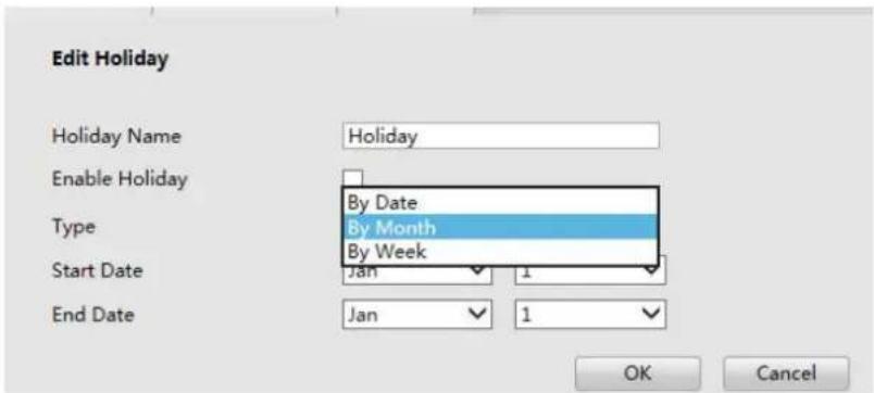
text_image
Edit Holiday Holiday Name Holiday Enable Holiday Type By Date By Month By Week Start Date Jan 1 End Date Jan 1 OK CancelF-4.5.40
4.5.4.5 User
Step1. Enter user setting menu by clicking SettingSystem→User.
Note:
- If the NVR firmware version out of the factory is xx.7.0.6 or above, the default user name is "admin" and the default password is "ms1234";
- If the NVR firmware is upgraded to xx.7.0.6 or above from a lower version, the default password will turn to "ms1234" after a reset, or it will keep the old default password "123456";
- If the NVR firmware version is below xx.7.0.6, the default user name is "admin" and the default password is "123465".
Step2. Add new user.
Click [Add] to enter add user menu, input information for the new user, select user level and set user privileges, then click [OK] to save settings.
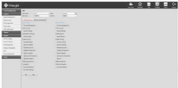
text_image
Mileight Local Settings C:\Users\Networks\Network Components\Network Link FPC Configuration Access Web USB Connection Name: System General Settings Active Data Link Data Management Web Management Web Management Web Management Web Management Web Management Web Management Web Management Web Management Web Management Web Management Web Management Web Management Web Management Web Management Web Management Web Management Web Management Web Management Web Management Web Management Web Management Web Management Web Management Web Management Web Management Web Management Web Management Web Management Web Management Web Management Web Management Web Management Web Management Web Maintenance Web Maintenance Web Maintenance Web Maintenance Web Maintenance Web Maintenance Web Maintenance Web Maintenance Web Maintenance Web Maintenance Web Maintenance Web Maintenance Web Maintenance Web Maintenance Web Maintenance Web Maintenance Web Maintenance Web Maintenance Web Maintenance Web Maintenance Web Maintenance Web Maintenance Web Maintenance Web Maintenance Web Maintenance Web Maintenance Web Maintenance Web Maintenance Web Maintenance Web Maintenance Web Maintenance Web Maintenance Web Maintenance Web MaintenanceF-4.5.41
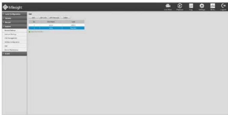
text_image
Milesight Local Configuration Parameters Report Application Device Settings External Settings Data Management Web Development User Device Properties Build Add Edit Edit Options Edit... Add... Save... Save... Save... Save... Save... Save... Save... Save... Save... Save... Save... Save... Save... Save... Save... Save... Save... Save... Save... Save... Save... Save... Save... Save... Save... Save... Save... Save... Save... Save... Save... Save... Save... Save... Save... Save... Save... Save... Save... Save... Save... Save... Save... Save... Save... Save... Save... Save... Save... Save... Sines Sines Sines Sines Sines Sines Sines Sines Sines Sines Sines Sines Sines Sines Sines Sines Sines Sines Sines Sines Sines Sines Sines Sines Sines Sines Sines Sines Sines Sines Sines Sines Sines Sines Tires Tires Tires Tires Tires Tires Tires Tires Tires Tires Tires Tires Tires Tires Tires Tires Tires Tires Tires Tires Tires Tires Tires Tires Tires Tires Tires Tires Tires Tires Tires Tires Tires TiresF-4.5.42
Step3. Edit user.
Select a desired user and click, when the color below changes into blue, click [Edit Limit] to edit user privileges, click [Edit Password] to change password.
Note:
- User name can be comprised of letters and figures. The user level is separated into User and Operator with different authority;
- [Local Privilege] means the privilege to the monitor connected with NVR, while the [Remote Privilege] means the privilege to web settings.
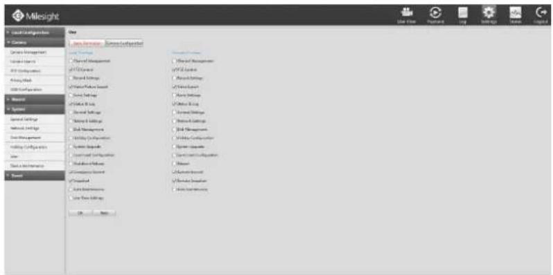
text_image
Milesight Local Configurations General System Management System Manager All Components Active Data Data Configuration System System System Settings System Settings System Settings System Settings System Settings System Settings System Settings System Settings System Settings System Settings System Settings System Settings System Settings System Settings System Settings System Settings System Settings System Settings System Settings System Settings System Settings System Settings System Settings System Settings System Settings System Settings System Settings System Settings System Settings System Settings System Settings System Settings System Settings System SettingsF-4.5.43
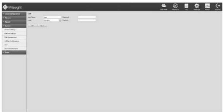
text_image
Milesight Local Configuration Course Record System Local Settings Local Settings End Management Mobile Configurations User Device Properties TrackF-4.5.44
Step4. Click to delete a user.
4.5.4.6 Device Maintenance
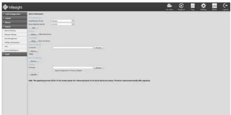
text_image
Milesight Local Configurations Camera Mouse System Service Settings Network Settings Data Management Data Configuration Data Preferences Search SKE's Workforce Application Status: 3 Months Base Command/Control: 3 Months File Default... Default... Default... Default... Default... Default... Default... Default... Default... Default... Default... Default... Default... Default... Default... Default... Default... Default... Default... Default... Default... Default... Default... Default... Default... Default... Default... Default... Default... Default... Default... Default... Default... Default... Default... Default... Default... Default... Default... Default... Default... Default... Default... Default... Default... Default... Default... Default... Default... Default... Default Default Default Default Default Default Default Default Default Default Default Default Default Default Default Default Default Default Default Default Default Default Default Default Default Default Default Default Default Default Default Default Default Default Default Default Default Default Default Default Default Default Default Default Default Default Default Default Default Default DefaultF-4.5.45
4.5.4.6.1 Auto Maintenance
You can set the Log and Photo Retention period for Log and Photo. Once is expired, it will automatically delete by NVR. The retention period is ranged from 1 to 12 months, if you don't want those files be deleted, you can select Permanent.
4.5.4.6.2 Reboot
Click to reboot the NVR.
4.5.4.6.3 Reset
Click to reset the NVR to factory defaults.
4.5.4.6.4 Import Config File
Click to select one desired file and click to restore the NVR configuration.
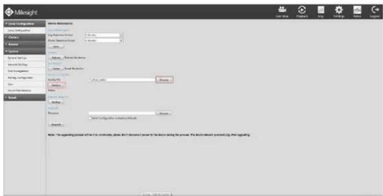
text_image
Milesight File Configuration Local Configuration Canvas Browse Systems Special Server Network Storage Final Management All-Log Configuration Size Local Parameters Stream Name: Milelight File Path: 100% Name: 100% System Path: 100% System Path: 100% System Path: 100% System Path: 100% System Path: 100% System Path: 100% System Path: 100% System Path: 100% System Path: 100% System Path: 100% System Path: 100% System Path: 100% System Path: 150% System Path: 150% System Path: 150% System Path: 150% System Path: 150% System Path: 150% System Path: 150% System Path: 150% System Path: 150% System Path: 150% System Path: 150% System Path: 150% System Path: 150% SystemPath: 150% SystemPath: 150% SystemPath: 150% SystemPath: 150% SystemPath: 150% SystemPath: 150% SystemPath: 150% SystemPath: 150% SystemPath: 150% SystemPath: 150% SystemPath: 150% SystemPath: 150% SystemPath: 125% SystemPath: 125% SystemPath: 125% SystemPath: 125% SystemPath: 125% SystemPath: 125% SystemPath: 125% SystemPath: 125% SystemPath: 125% SystemPath: 125% SystemPath: 125% SystemPath: 125% SystemPath: 125% SystemPath: Note: The existing process will be the following problem. But it's done prior to the device during the process. The device contains system(s) or other reporting. Source: Caikei@mslight.comF-4.5.46
4.5.4.6.5 Export Config File
Click to backup present settings.
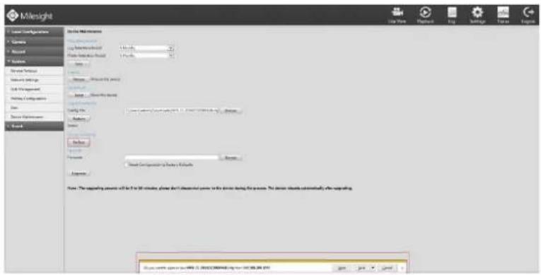
text_image
Milesight File Path Path Name: Mileslight View Path: 100% View Path: 100% View Path: 100% View Path: 100% View Path: 100% View Path: 100% View Path: 100% View Path: 100% View Path: 100% View Path: 100% View Path: 100% View Path: 100% View Path: 100% View Path: View Path: View Path: View Path: View Path: View Path: View Path: View Path: View Path: View Path: View Path: View Path: View Path: View Path: View Path: View Path: View Path: View Path: View Path: View Path: View Path: View Path: View Path: View Path: View Path: View Path: View Path: View Path: View Path: View Path: View Path: View Path: View Path: View Path: View Path: View Path: View Path: View Path: View Path: View Path: View Path: View Path: View Path: View Path: View Path: View Path: View Path: View Path: View Path: View Path: View Path: View Path: View Path: View Path: View Path: View Path:F-4.5.47
4.5.4.6.6 Upgrade
Click to select the firmware file, and check if reset configuration to factory defaults. Then click
Upgrade
to upgrade.
Note:
The upgrading process will be 5 to 10 minutes, please don't disconnect power to the device during the process. The device reboots automatically after upgrading.
4.5.5 Event
4.5.5.1 Video Loss
Step1. Enter video loss configuration interface by clicking SettingEvent→Video Loss.
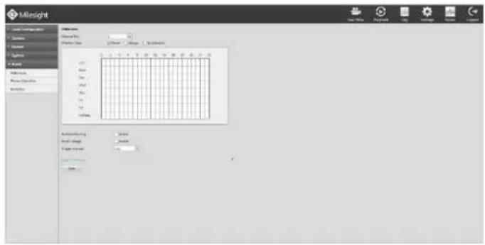
text_image
Milesight Name: Milesight Description: Name: Milesight Source: Milesight Date: 2015-04-23 Time: 12:00-17:00 Address: Milesight Address: Milesight Address: Milesight Address: Milesight Address: Milesight Address: Milesight Address: Milesight Address: Milesight Address: Milesight Address: Milesight Address: Milesight Address: Milesight Address: Milesight Address: Milesight Address: Milesight Address: Milesight Address: Milesight Address: N/A Address: N/A Address: N/A Address: N/A Address: N/A Address: N/A Address: N/A Address: N/A Address: N/A Address: N/A Address: N/A Address: N/A Address: N/A Address: N/A Address: N/A Address: N/A Address: N/A Address: N/A Address: N/A Address: N/A Address: N/AA Address: N/AA Address: N/AA Address: N/AA Address: N/AA Address: N/AA Address: N/AA Address: N/AA Address: N/AA Address: N/AA Address: N/AA Address: N/AA Address: N/AA Address: N/AA Address: N/AA Address: N/AA Address: N/AA Address: Milesight Address: Milesight Address: Milesight Address: Milesight Address: Milesight Address: Milesight Address: Milesight Address: Milesight Address: Milesight Address: Milesight Address: Milesight Address: Milesight Address: Milesight Address: Milesight Address: Milesight Address: Milesight Address: S/NAAF-4.5.48
Step2. Select a desired channel
Step3. Select effective time to setup when you want to trigger actions once video loss is detected.
[Never]: Your NVR will not trigger any actions when [Never] button is checked. No matter the [Audible Warning] or [Email Linkage] check-boxes are checked or not.
[Always]: Your NVR will always trigger actions when [Always] button is checked. Please make sure [Audible
Warning] or [Email Linkage] is checked.
[By Schedule]: Schedule can be set for all week or any day of the week with up to 12 time periods per day. Video loss actions take effect in the scheduled period only.
[Audible Warning]: Trigger an audible beep when video loss is detected
[Email Linkage]: Send video loss note to specified email address when video loss is detected.(Please refer to 4.5.4.2.4 Email configuration for mail address setting)
[Trigger Interval]: Set the interval between two events.
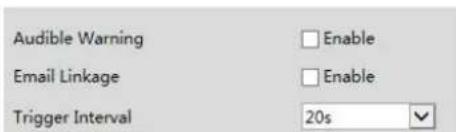
text_image
Audible Warning Enable Email Linkage Enable Trigger Interval 20s4.5.5.2 Motion Detection
Step1. Enter motion detection setting interface by clicking Settings→Event→Motion Detection.
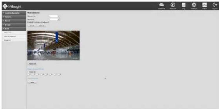
text_image
Milesight Local Configuration Category Material System Design Data Network Data & Settings Design Data Analysis Data Analysis Data Analysis Data Analysis Data Analysis Data Analysis Data Analysis Data Analysis Data Analysis Data Analysis Data Analysis Data Analysis Data Analysis Data Analysis Data Analysis Data Analysis Data Analysis Data Analysis Data Analysis Data Analysis Data Analysis Data Analysis Data Analysis Data Analysis Data Analysis Data Analysis Data Analysis Data Analysis Data Analysis Data Analysis Data Analysis Data Analysis Data Analysis Data Analysis Dashed Line Analysis Dashed Line Analysis Dashed Line Analysis Dashed Line Analysis Dashed Line Analysis Dashed Line Analysis Dashed Line Analysis Dashed Line Analysis Dashed Line Analysis Dashed Line Analysis Dashed Line Analysis Dashed Line Analysis Dashed Line Analysis Dashed Line Analysis Dashed Line Analysis Dashed Line Analysis Dashed Line Analysis Dashed Line Analysis Dashed Line Analysis Dashed Line Analysis Dashed Lined Line Analysis Dashed Lined Line Analysis Dashed Lined Line Analysis Dashed Lined Line Analysis Dashed Lined Line Analysis Dashed Lined Line Analysis Dashed Lined Line Analysis Dashed Lined Line Analysis Dashed Lined Line Analysis Dashed Lined Line Analysis Dashed Lined Line Analysis Dashed Lined Line Analysis Dashed Lined Line Analysis Dashed Lined Line Analysis Dashed Lined LineF-4.5.49
Step2. Set the trigger area for motion detection.
You can set the area by dragging the mouse on live view window. Meanwhile, the area will be synchronized in the camera.
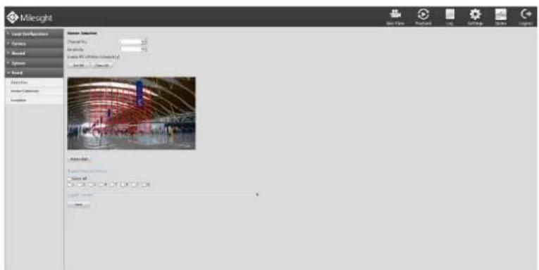
text_image
Milesight Material Selection Material Type: 100% Material Location: (C:\Users\1\Users\1\Users\1\Users\1\Users\1\Users\1\Users\1\Users\1\Users\1\Users\1\Users\1\Users\1\Users\1\Users\1\Users\1\Users\1\Users\1\Users\1\Users\1\Users\1\Users\1\Users\1\Users\1\Users\1\Users\1\Users\1 Add to: Add to: Add to: Add to: Add to: Add to: Add to: Add to: Add to: Add to: Add to: Add to: Add to: Add to: Add to: Add to: Add to: Add to: Add to: Add to: Add to: Add to: Add to: Add to: Add to: Add to: Add to: Add to: Add to: Add to: Add to: Add to: Add to: Add to: All All All All All All All All All All All All All All All All All All All All All All All All All All All All All All All All All All All All All All All All All All All All All All All All All All AllF-4.5.50
Step3. Select the schedule, sensitivity and trigger area for motion detection.
[Enable IPC's Motion]: If it is enabled here, motion detect will take effect 7*24h; If it is not enabled, motion detect will take effect as the schedule which is set on the camera web.
[All Set]: Set all area as the trigger area;
[All Clear]: Clear all trigger area;
[Sensitivity]: Set sensitivity for motion detection, range from 1 to 10. It will synchronize to IPC if you set sensitivity here;
Step4. Click the [Action Edit] to edit action once motion is detected.
Edit the schedule and action.
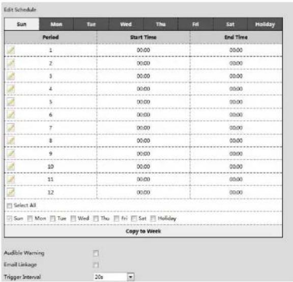
text_image
Edit Schedule Sun Mon Tue Wed Thu Fri Sat Holiday Period Start Time End Time 1 00:00 00:00 2 00:00 00:00 3 00:00 00:00 4 00:00 00:00 5 00:00 00:00 6 00:00 00:00 7 00:00 00:00 8 00:00 00:00 9 00:00 00:00 10 00:00 00:00 11 00:00 00:00 12 00:00 00:00 Select All Sun Mon Tue Wed Thu Fri Sat Holiday Copy to Week Audible Warning Email Linkage Trigger Interval 20sF-4.5.51
[Audible Warning]: NVR will audible warning once motion is detected;
[Email Linkage]: NVR will send an email to the address set before.
Note:
Motion record schedule is different from the schedule of the [Audible] and [Email Linkage]. Enter the Record Schedule by clicking Settings→Record→Record Schedule. Confirm the time to enable Motion Record.
Step5. Select the desired channel and check to configure motion detection action.
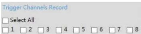
text_image
Trigger Channels Record □ Select All □ 1 □ 2 □ 3 □ 4 □ 5 □ 6 □ 7 □ 84.5.5.2 Exception
Step1. Enter Exception by clicking Settings→Event→Exception.
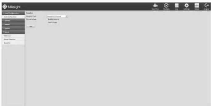
text_image
Milesight Properties Properties Properties Properties Properties Properties Properties Properties Properties Properties Properties Properties Properties Properties Properties Properties Properties Properties Properties Properties Properties Properties Properties Properties Properties Properties Properties Properties Properties Properties Properties Properties Properties Properties Properties Properties Properties Properties Properties Properties Properties Properties Properties Properties Properties Properties Properties Properties Properties Properties Helps Helps Helps Helps Helps Helps Helps Helps Helps Helps HelpsF-4.5.52
Step2. Select Exception Type. There are 4 kinds of alarm types.
[Network Disconnected]: Loss of network;
[HDD Full]: HDD is full. It usually happened when Recycle Mode is OFF.
[Record Fail]: Record Failed, including HDD Error, HDD Full, no HDD and so on.
[HDD Error]: HDD is Error.
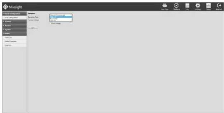
text_image
Mileigh New User New Info New Image New Image New User New Info New ImageF-4.5.53
Step3. Select alarm type.
[Audible Warning]: Audio alarm will be ready to be triggered if checked;
[Email Linkage]: Email will be ready to sent if checked.
4.6 Status
You can have a quick view of the information of the device, network, camera, disk and event. This part is only for your rapid reference. If you want to make any configuration, please go to corresponding parts accordingly.
4.6.1 Device Information
Step: Enter Device information menu by clicking Settings→Status→Device Information
It will show you information in F-4.6.1, including: Device ID, Device Name, Hardware Version, Software Version, Serial Number, and up time.
text_image
Milesight Data Profile Profile Data Source Data Source Data Source Data Source Data Source Data Source Data Source Data Source Data Source Data Source Data Source Data Source Data Source Data Source Data Source Data Source Data Source Data Source Data Source Data Source Data Source Data Source Data Source Data Source Data Source Data Source Data Source Data Source Data Source Data Source Data Source Data Source Data Source Data Source Dots Source Dots Source Dots Source Dots Source Dots Source Dots Source Dots Source Dots Source Dots Source Dots Source Dots Source Dots Source Dots Source Dots Source Dots Source Dots Source Dots Source Dots Source Dots Source Dots Source Dots Source Dots Source Dots Source Dots Source Dots Source Dts Source Dts Source Dts Source Dts Source Dts Source Dts Source Dts Source Dts Source Dts Source Dts Source Dts Source Dts Source Dts Source Dts Source Dts Source Dts Source Dts Source Dts Source Dts Source Dts Source Dts Source Dts Source Dts Source Dts Source Dts Source Dls Source Dls Source Dls Source Dls Source Dls Source Dls Source Dls Source Dls Source Dls Source Dls Source Dls Source Dls Source Dls Source Dls Source Dls Source Dls Source Dls Source Dls Source Dls Source Dls Source Dls Source Dls Source Dls Source Dls Source Dls Source Ds Source Ds Source Ds Source Ds Source Ds Source Ds Source Ds Source Ds Source Ds Source Ds Source Ds Source DsF-4.6.1
4.6.2 Network Status
Step: Enter Network Status menu by clicking Settings→Status→Network Status
It will show you information in F-4.6.2, including: Free bandwidth, Used bandwidth, Connection, Mode, DHCP, MTU(B), IP Address, Net mask, Gateway, MAC, Preferred DNS Server, Alternate DNS Server, Receive Rate, and Send Rate.
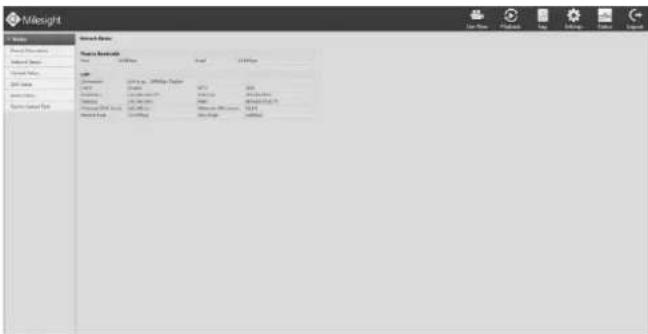
text_image
Mail about Mail on Date Value Mail on Date Value Mail on Value Mail on Value Mail on Value Mail on Value Mail on Value Mail on Value Mail on Value Mail on Value Mail on Value Mail on Value Mail on Value Mail on Value Mail on Value Mail on Value Mail on Value Mail on Value Mail on Value Mail on Value Mail on Value Mail on Value Mail is not available to any other value.F-4.6.2
4.6.3 Camera Status
Step: Enter camera status menu by clicking Settingstatus→Camera Status
It will show you information in F-4.6.3, including: Channel, Name, Enable, IP Address, Record, Frame Rate, Bit rate, Resolution and Status.
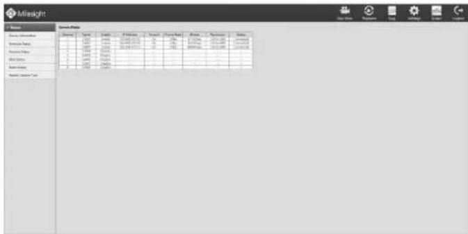
text_image
Mailbright Menu Options Name Type Name Finish Finish Date Finish Date Finish Date Finish Date Finish Date Mailbright 1 1 1 1 1 1 1 1 1 1 1 1 2 2 2 2 2 2 2 2 2 2 2 2 3 3 3 3 3 3 3 3 3 3 3 3 4 4 4 4 4 4 4 4 4 4 4 5 5 5 5 5 5 5 5 5 5 5 6 6 6 6 6 6 6 6 6 6 6 7 7 7 7 7 7 7 7 7 7 8 8 8 8 8 8 8 8 8 8 9 9 9 9 9 9 9 9 9 9 Maillight Maillight Maillight Maillight Maillight Maillight Maillight Maillight Maillight Maillight Maillight Maillight Maillight Maillight Maillight Maillight Maillight Maillight Maillight Maillight Maillight Maillight Maillight Maillight Maillight Maillight Maillight Maillight Maillight Maillight Maillight Maillight Maillight MaillightF-4.6.3
4.6.4 Disk Status
Step: Enter disk status menu by clicking Settings→Status→Disk Status
It will show you information in F-4.6.4, including: Port, Vendor, status, Total(GB), Used(GB) Free space(GB), HDD Type, In Use, and Recycle Mode. You can see the Total Capacity (GB) and Available Capacity (GB) as below:
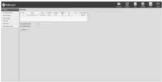
text_image
M&NSight File Properties Type: New Size: 100000000 Name: M&NSight@1.2.1 - Microsoft Teams Address: 432-567-899 Edit Tools Add Options Save Asseptin Save Asseptin Data Save Asseptin Data Importing Asseptin Data Importing Asseptin Data Importing Asseptin DataF-4.6.4
4.6.5 Event Status
Step: Enter event status menu by clicking SettingStatus→Event Status
It will show you information in F-4.6.5, including: Channel, Name, IP Address, Videoloss, Motion, I/O. Icon will light up as below:
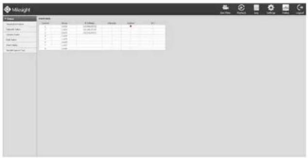
text_image
Weight Name: 10.0000 Value: 10.0000 Error: 0.0000 Error Rate: 0.0000 Error Width: 0.0000 Error Mode: 0.0000 Error Time: 0.0000 Error Range: 0.0000 Error Frequency: 0.0000 Error Time: 0.0000 Error Range: 0.0000 Error Mode: 0.0000 Error Time: 0.0000 Error Range: 0.0000 Error Mode: 0.0000 Error Time: 0.0000 Error Range: 0.0000 Error Mode: 0.0000 Error Time: 0.0000 Error Range: 0.0000 Error Mode: 1.25% 2.5% 3.7% 4.9% 6.1% 7.3% 8.5% 9.7% 10.9% 12.1% 13.3% 14.5% 15.7% 16.9% 18.1% 19.3% 20.5% 21.7% 22.9% 24.1% 25.3% 26.5% 27.7% 28.9% 29.1% 30.3% 31.5% 32.7% 33.9% 35.1% 36.3% 37.5% 38.7% 39.9% 41.1% 42.3% 43.5% 44.7% 45.9% 47.1% 48.3% 49.5% 50.7% 51.9% 53.1% 54.3% 55.5% 56.7% 57.9% 59.1% 60.3% 61.5% 62.7% 63.9% 65.1% 66.3% 67.5% 68.7% 69.9% 71.1% 72.3% 73.5% 74.7% 75.9% 77.1% 78.3% 79.5% 80.7% 81.9% 83.1% 84.3% 85.5% 86.7% 87.9% 89.1% 90.3% 91.5% 92.7% 93.9% 95.1% 96.3% 97.5% 98.7% 99.9% 101.1%F-4.6.5
4.6.6 Packet Capture Tool
Step: Enter packet capture tool status menu by clicking Settings→Status→Packet Capture Tool
Print IP and Port, click the [Start] to start capture packet then click [End] to stop. Click [Download] to backup packet locally.
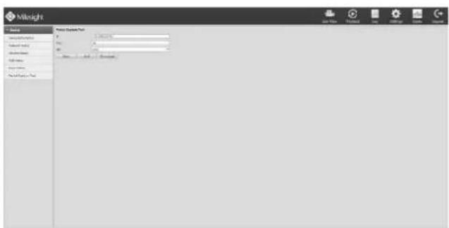
text_image
Milknight Data Options Help Data Type: 100% Data Source: All Data Details: All Data History: All Data Analysis: All Data Summary: All Data Output: All Data Review: All Data Support: All Data Security: All Data Management: All Data Security Details: All Data Security Status: All Data Security Description: All Data Security Description Status: All Data Security Description Status: All Data Security Description Status: All Data Security Description Status: All Data Security Description Status: All Data Security Description Status: All Data Security Description Status: All Data Security Description Status: All Data Security Description Status: All Data Security Description Status: All Data Security Description Status: All Data Security Description Status: All Data Security Description Status: All Data Security Description Status: All Data Security Description Status:All Data Security Description Status:All Data Security Description Status:All Data Security Description Status:All Data Security Description Status:All Data Security Description Status:All Data Security Description Status:All Data Security Description Status:All Data Security Description Status:All Data Security Description Status:All Data Security Description Status:All Data Security Description Status:All Data Security Description Status:All Data Security Description Status:All Data Security Description Status:All Dial Data Available, No. 1, 2, 3, 4, 5, 6, 7, 8, 9, 10, 11, 12, 13, 14, 15, 16, 17, 18, 19, 20, 21, 22, 23, 24, 25, 26, 27, 28, 29, 30, 31, 32, 33, 34, 35, 36, 37, 38, 39, 40, 41, 42, 43, 44, 45, 46, 47, 48, 49, 50, 51, 52, 53, 54, 55, 56, 57, 58, 59, 60, 61, 62, 63, 64, 65, 66, 67, 68, 69, 70, 71, 72, 73, 74, 75, 76, 77, 78, 79, 80, 81, 82, 83, 84, 85, 86, 87, 88, 89, 90, 91, 92, 93, 94, 95, 96, 97, 98, 99, 100F-4.6.6
4.7 Logout
Click [Logout] to exit the current account.
text_image
Mileight System Capture Tool engang for message engang! OK... Cancel...F-4.7.1
5. Services
Milesight Technology Co., Ltd provides customers with timely and comprehensive technical support services.
End-users can contact your local dealer to obtain technical support. Distributors and resellers can contact directly with Milesight for technical support.
Technical Support Mailbox: support@milesight.com
Web: http://www.milesight.com
Online Problem Submission System: http://www.milesight.com/support/feedback.asp
Address: No.23 Wanghai Road, 2nd Software Park, Xiamen, China
Zip Code: 361006
TEL: +86-592-5922772
FAX: +86-592-5922775
Milesight More in Sight