
DXY-1350A - Traceur graphique ROLAND - Free user manual and instructions
Find the device manual for free DXY-1350A ROLAND in PDF.


| Product Type | Flatbed Plotter |
| Dimensions (W x D x H) | 615 mm x 412 mm x 113 mm (24-1/4 x 16-1/4 x 4-1/2 in) |
| Weight | 5.7 kg (12.6 lb) |
| Power Supply | Exclusive AC adapter: DC +9.7 V/0.7 A, +31 V/0.7 A |
| Maximum Plotting Speed | 600 mm/s (23-5/8 in/s) in FAST mode |
| Mechanical Resolution | 0.0125 mm/step (micro-step control) |
| Software Resolution | 0.025 mm/step (RD-GL I/II) or 0.1 mm/step (DXY-GL) |
| Number of Pens | 8 |
| Supported Paper Sizes | ISO A3, A4; ANSI A, B |
| Paper Holding Method | Electrostatic adsorption (DXY-1350A) |
| Interface | Parallel (Centronics) and Serial (RS-232C) |
| Buffer Size | 1 Mbyte (384 Kbyte for replot buffer) |
| Instruction Sets | DXY-GL, RD-GL I, RD-GL II |
| Acoustic Noise Level | Standby: <27 dB(A); Drawing: <59 dB(A) (ISO 7779) |
| Operating Temperature | 5 to 40°C (41 to 104°F) |
| Operating Humidity | 20% to 80% (non-condensing) |
| Included Accessories | Stands (L and R), AC adapter, standard ceramic pen set, self-test paper, positioning stickers, dust cover, user manual, drivers for Windows 3.1/95 |
| Maintenance & Cleaning | Clean main unit with water or anhydrous alcohol; clean drawing board with ethyl alcohol only; never use water, detergents, or silicone cloth on electrostatic pad |
| Safety Precautions | Do not disassemble; use only specified AC adapter; avoid liquids and metal objects inside; unplug when not in use for extended periods |
Frequently Asked Questions - DXY-1350A ROLAND
User questions about DXY-1350A ROLAND
0 question about this device. Answer the ones you know or ask your own.
Ask a new question about this device
Download the instructions for your Traceur graphique in PDF format for free! Find your manual DXY-1350A - ROLAND and take your electronic device back in hand. On this page are published all the documents necessary for the use of your device. DXY-1350A by ROLAND.
USER MANUAL DXY-1350A ROLAND
Thank you very much for purchasing the DXY-1350A/1150A.
- To ensure correct and safe usage with a full understanding of this product's performance, please be sure to read through this manual completely and store it in a safe location.
- Unauthorized copying or transferral, in whole or in part, of this manual is prohibited.
- The contents of this operation manual and the specifications of this product are subject to change without notice.
- The operation manual and the product have been prepared and tested as much as possible. If you find any misprint or error, please inform us.
For the USA
FEDERAL COMMUNICATIONS COMMISSION RADIO FREQUENCY INTERFERENCE STATEMENT
This equipment has been tested and found to comply with the limits for a Class A digital device, pursuant to Part 15 of the FCC Rules.
These limits are designed to provide reasonable protection against harmful interference when the equipment is operated in a commercial environment.
This equipment generates, uses, and can radiate radio frequency energy and, if not installed and used in accordance with the instruction manual, may cause harmful interference to radio communications.
Operation of this equipment in a residential area is likely to cause harmful interference in which case the user will be required to correct the interference at his own expense.
Unauthorized changes or modification to this system can void the users authority to operate this equipment.
The I/O cables between this equipment and the computing device must be shielded.
For Canada
CLASS A
NOTICE
This Class A digital apparatus meets all requirements of the Canadian Interference-Causing Equipment Regulations.
CLASSE A
AVIS
⚠️ To Ensure Safe Use 2
⚠️ About the Labels Affixed to the Unit 4
Checking Accessories 5
Part Names and Functions ...... 6
Step-by-Step Plotting 8
Setting Up the Stands 9
Connection 10
Loading the Pens 10
Loading the Paper 11
Self-testing 13
Installing the DRIVER.... 13
Downloading Plot Data 14
After Plotting 16
Care and Maintenance 16
Explanation of Functions and Operation 17
Pens 18
Paper 21
Plotting Area 22
DIP Switches 24
What to Do If... 26
List of DXY-GL Related Instructions 28
List of RD-GL I Related Instructions 29
List of RD-GL II Related Instructions 31
The Specifications of the Interface 35
List of Optional Cables 38
List of Character Sets 39
Specification of DXY-1350A/1150A 42
Windows is a registered trademark or trademark of Microsoft Corporation in the United States and/or other countries.
To Ensure Safe Use
About ⚠️M&ARNICES
CAUTION
 | Used for instructions intended to alert the user to the risk of death or severe injury should the unit be used improperly. |
 | Used for instructions intended to alert the user to the risk of injury or material damage should the unit be used improperly.* Material damage refers to damage or other adverse effects caused with respect to the home and all its furnishings, as well to domestic animals or pets. |
About the Symbols
 | The symbol alerts the user to important instructions or warnings. The specific meaning of the symbol is determined by the design contained within the triangle. The symbol at left means "danger of electrocution." |
 | The symbol alerts the user to items that must never be carried out (are forbidden). The specific thing that must not be done is indicated by the design contained within the circle. The symbol at left means the unit must never be disassembled. |
 | The symbol alerts the user to things that must be carried out. The specific thing that must be done is indicated by the design contained within the circle. The symbol at left means the power-cord plug must be unplugged from the outlet. |

WARNING

Do not disassemble, repair, or modify.
Doing so may lead to fire or abnormal operation resulting in injury.

Do not use with any power supply other than the dedicated AC adapter.
Use with any other power supply may lead to fire or electrocution.

Do not use with any electrical power supply that does not meet the ratings displayed on the AC Adapter.
Use with any other power supply may lead to fire or electrocution.

CAUTION

Do not use with a damaged power cord or a power outlet that is loose when the AC adapter is plugged in.
Use with any other power supply may lead to fire or electrocution.

natural_image
Simple line drawing of a cable being inserted into a wall socket (no text or symbols)
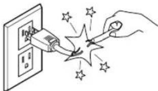
When unplugging the electrical power cord from the power outlet, grasp the plug, not the cord.
Unplug- ging by pulling the cord may damage it, leading to fire or elect
natural_image
Illustration of a hand inserting a plug into an electrical outlet with sparkles (no text or symbols)
Install on a stable surface.
Failure to do so may result in falling of the unit or AC adapter, leading to injury.

natural_image
Simple line drawing of a seesaw on an inclined plane with motion lines indicating speed (no text or symbols)
Do not allow liquids, metal objects or flammables inside the machine.
Fire may result.

natural_image
Illustration of a hand-drawn tool with a bucket pouring liquid into a tray, alongside three clamps and a handle (no text or symbols)
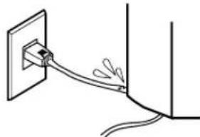
Do not injure or modify the electrical power cord, nor subject it to excessive bends, twists, pulls, binding, or pinching, nor place any object of weight on it.
Doing so may damage the electrical power cord,
leading to electrocu- tion or fire.
natural_image
Simple line drawing of a cable being inserted into a wall socket (no text or symbols)
When not in use for prolonged periods, unplug the power cord from the electrical outlet.
Failure to do so may result in danger of shock, electrocution, or fire due to deterioration of the electrical insulation.


Do not damage the electrostatic pad, or attempt to use tacks or the like to secure paper or other material to the pad.
Doing so may lead to electrocution.

natural_image
Simple line drawing of a pushpin with a circular head and lightning bolts (no text or symbols)About the Labels Affixed to the Unit
These labels are affixed to the body of this product.
The following figure describes the location.

In addition to the are also used.
⚠️WARNING ⚠CAUTION
NOTICE

: Indicates information to prevent machine breakdown or malfunction and ensure correct use.
: Indicates a handy tip or advice regarding use.
Checking Accessories
The following accessories are packed together with the main unit. Before using, be sure to check to make sure that all accessories have been included.
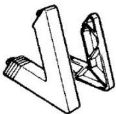
Stand x 2 ( L and R) Exclusive AC adapter x 1
Metal strip (DXY-1150A only) x 3
natural_image
Abstract geometric line drawing of two intersecting 3D shapes (no text or symbols)Paper clip (DXY-1150A only) x 1

Rubber positioning sticker x 1 set

natural_image
Pure diagram of five parallel cylindrical rods without any text or symbolsTransparent positioning sticker x 1 set

PLOTTER DRIVER for Windows® 3.1 x 1

PLOTTER DRIVER for Windows® 95 x 1

Paper ( for self-test ) x 2

Standard ceramic pen (for self-test) x 1 set

Dust cover x 1

natural_image
Simple line drawing of two overlapping papers or documents (no text or symbols)User's manual x 1


Part Names and Functions
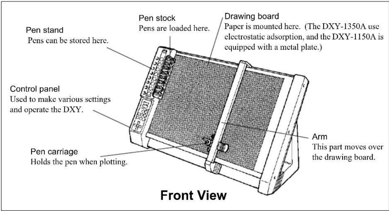

Control Panel


REPLOT LED (DXY-1350A only)
Lights up when replotting is possible.
[REPLOT MODE] key (DXY-1350A only)
Switches to the Replot mode. (See "Explanation of Functions and Operation".)
[REPLOT] key (DXY-1350A only)
Press this key while the REPLOT MODE LED is lit to execute replotting.
[PAPER HOLD] key (DXY-1350A only)
Causes paper to stick to the drawing board.
PAPER HOLD LED (DXY-1350A only)
Lights up during paper hold.
[PEN UP/DOWN] key
Press this key to move the pen up or down.
[ENTER] key
Use this key in combination with other keys to operate the DXY.

[P1] and [P2] scaling point keys
Pressing the [P1] or [P2] key moves the pen carriage to the specified position. (See "Explanation of Functions and Operation".)

[VIEW] key
Moves the carriage to the upper right of the drawing board and pauses operation. Pressing the key a second time return the pen carriage to the pen position it was at immediately before.
VIEW LED
Lights up during VIEW

[FAST] key
Pressing this key speeds up carriage movement.


Moves the pen carriage. Pressing two adjacent position keys at the same moves the pen carriage diagonally.

POWER/ERROR LED
Lights up when the power is turned on. This LED also blinks when an error has occurred.
On the DXY-1150A, only the pen number is shown. The following functions are available only on the DXY-1350A.

[PENSELECT] key
The pen to be used can be selected while this key is held down.
Step-by-Step Plotting
Operation Flow
When using the DXY, plotting is carried out using the sequence of steps described below. Refer to the pages indicated for each step for an explanation of how the operation is performed.
1 Set up the plotter.
2Connect the AC adapter.
3Connect the plotter to the computer.

4Select the instruction set.
5 Make other required settings.
6Load the pens.

7 Turn on the power.
8Load the paper.
9 Set pen speed.
10 Download plot data from the computer.
Aù
Perform self-testing.
Be sure to follow this procedure when using the DXY for the first time. If necessary, steps 4 and 5 should also be carried out.
These steps are carried out when the computer connection or the paper size has been changed. All of these settings are made using the DIP switches.
Unless the usage environment has been changed, these steps are all that needs to be done to make a plot.
When using the DXY for the first time, or to confirm operation of the plotter, a self-test can be carried out to check the main unit for problems.
Setting Up the Stands
NOTICE
Never install this unit in any of the following situations, as it could result in damage:
- Do not install the unit on an unstable surface.
- Places with excessive electrical noise.
- Places with excessive humidity or dust.
- The unit and AC adapter become hot during use. Avoid installation in an are a with poor heat-radiating characteristics (poor ventilation).
- Avoid subjecting the unit to severe vibration or shocks.
- Places exposed to strong illumination or direct sunlight.
To Use the DXY Upright
1
Install the left and right stands included with the plotter.

natural_image
Technical line drawing of a mechanical bracket or support structure (no text or symbols)2
To prevent interference with the arm when it moves, do not place any objects in the shaded area shown below.

To Use the DXY Horizontally
1
To prevent interference with the arm when it moves, do not place any objects in the shaded area shown below.

Connection
NOTICE
● Before connecting the cable, make sure the computer's power and the DXY's power switch are switched off.
- Securely connect the power cord, computer I/O cable and so on so that they will not be unplugged and cause failure during operation.
● The arm and pen carriage move when the unit is switched on and while performing plotting --keep hands and objects away at these times.
● The rail moves simultaneously when the power is switched on. Do not place an object on the drawing board.
● First switch on the power to the computer, then turn on the DXY.

flowchart
graph TD
    A["Host computer"] --> B["RS-232C connector"]
    B --> C["Parallel connector"]
    C --> D["AC Adapter"]
    D --> E["Parallel interface cable"]
    E --> F["Serial connector"]
    F --> G["Parallel connector"]
    G --> H["Power connector"]
    H --> I["Parallel connector"]
    I --> J["Serial connector"]
Loading the Pens
32 Color Plotter Pens Water Based Fiber Tipped Pen Thick Water Based Fiber Tipped Pen
Front

MPP Ink Pen Refillable Ink Pen Standard Ceramic Pen
Rear

About the Rubber Pen-cap Fitting
Before loading the pens make sure that the pen cap rubbers are set correctly (The pen cap rubber is mounted on the pen stock when the plotter is packed). The pen cap rubbers help prevent the pen tips from drying out, but they will not perform optimally unless they are mounted correctly.
Pen cap rubbers have fronts and backs, and either may be used depending on the type of pen each protects.
Removal

natural_image
Illustration of a hand using a tool to adjust or install a mechanical component (no text or symbols visible)Pull the pen cap rubber off. They can be relatively easily removed from mechanical pencils and ballpoint pens.
Mounting
While pressing the pen cap rubber on with your fingers, snap it onto the holder. Incorrect mounting may result in ink leakage and improper pen exchange.

NOTICE
- Load the pens only in the pen stock. Attempting to mount a pen directly in the pen carriage may cause faulty operation.
- Use only proprietary pens made exclusively for use with the DXY. Failure to do so may result in faulty operation because of differences in pen length.
● The effectiveness of the pen cap covers is only temporary. At the end of the work day, be sure to attach the special pen caps and store the pens.
Load the pens in the pen stock. The pen stock can hold eight pens at a time. Remove the cap from the pen, then while pressing down on the pen cap rubber with the tip of the pen as shown in the figure, gently press the pen into place so that the round ridge on the pen goes into the groove on the pen stock.
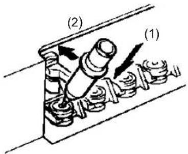
* When using ink pen Before loading into the pen stock, write lightly on a scrap of paper and check ink flow.
If the pen is not loaded correctly it will cause pen exchange errors. Be sure to load the pen correctly as shown below.

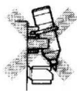
After use, remove the pens from the pen stock, cap securely, and store. Ink pen dry out especially rapidly, which can cause the ink at the tip to harden and interfere with normal use later.
Loading the Paper
* When using the plotter for the first time, be sure to peel the protective sheet (a sheet of thin, semitransparent vinyl) off the drawing board.

● Touching the surface of the paper with the hands may reduce plot quality because of the adsorption of skin oils.
- Adsorptive force may vary according to the type of paper. Adsorption of two or more sheets of paper is not possible.
- Adsorptive force is reduced in areas where temperature is extremely low. At such times, the paper will adsorb is allowed to stand for a short while (10 seconds) after placement on the drawing board. (DXY-1350A only)
- When opening a new package of paper, allow the paper to air for 30 minutes to an hour. This airing helps prevent contraction or expansion of the paper due to humidity or temperature.
How to Load Paper on the DXY-1350A
1
Make sure the PAPER HOLD LED is not lit.
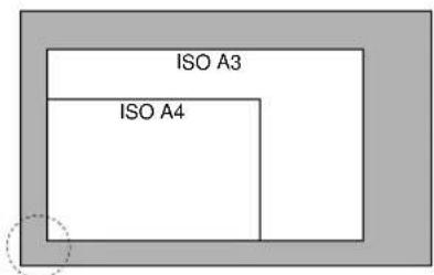
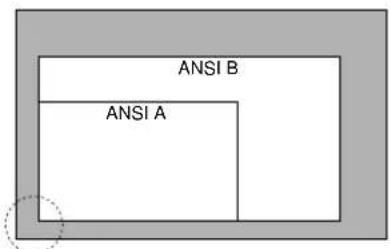
Place the paper according to its size as shown in the figure. (See a description of the plotting area.)

2
After positioning, turn on the [PAPER HOLD] key to secure the paper to the drawing board.

3
Remove bubbles and wrinkles from the paper by wiping with a dry cloth.

natural_image
Diagram of a hand pressing down on a mechanical component with directional arrows (no text or symbols)How to Load Paper on the DXY-1150A
1
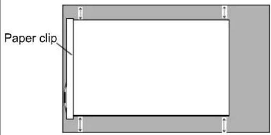
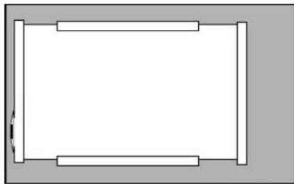
As shown in the figure, use the paper clip on the left side of the unit to align the sheet of paper evenly with the drawing board.
2
Remove bubbles and wrinkles from the paper, and install the metal plate on the left side of the sheet.

3
Install the metal plates at the top and bottom in the same way.
natural_image
Simple rectangular diagram with horizontal bars and a small arrow at the top-left corner (no text or symbols)Rubber Positioning Stickers and Transparent Positioning Sticker
After plotting has been carried out a few times and the position of the paper becomes apparent, affix the transparent and rubber positioning stickers included with the plotter to the drawing board. This enables
paper to loaded at the same place every time.

Self-testing
NOTICE
The arm and pen carriage move when the unit is switched on and while performing plotting --keep hands and objects away at these times.
Self-test Mode
A self-test can be carried out to check whether the DXY is functioning correctly. When doing this, the plotter does not have to be connected to the computer.
-
Load the pens included with the plotter in pen stocks 1 through 3. (See "Loading Pens.")
-
Turn on the power switch while holding down the [ENTER] key.
-
The pen carriage moves to the upper right of the main unit, and VIEW is enable (the VIEW LED lights up.)
-
Load an A3-size sheet of paper. (For instructions on loading paper, see "Loading the Paper" on pages 8 and 9 for the DXY-1350A or on page 9 for the DXY-1150A.)
-
Press the [VIEW] key to disable VIEW.
-
The DXY then plots the self-test pattern. When the pen is returned to the pen stock and the carriage moves to the upper right of the main unit, the self-test is finished.
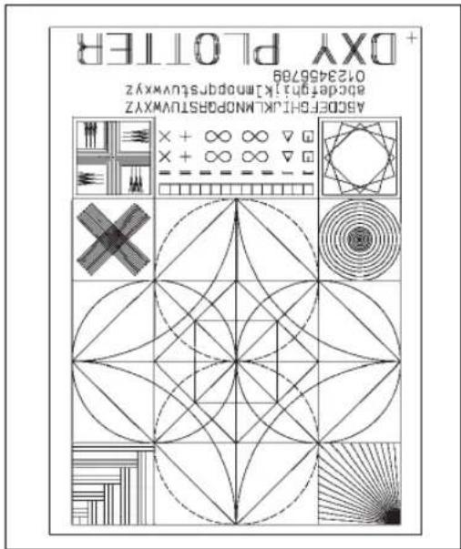
This is actually the bottom of the page.
The self-test plot is slightly larger than A4 size, so be sure to use A3-size paper.
Installing the DRIVER
The DXY-1350A/1150A comes with drivers for Windows 3.1 and Windows 95. Be sure to install the correct driver for your operating system.
About Installation
Be sure to read the notes on how to install the driver in the file Readme.doc on the Setup disk. In addition to an explanation of installation and setup methods, this file contains the latest information about the driver, the operating environment, and other important matters. You can view this file with a text editor such as Notepad.
Downloading Plot Data
Plot data is sent from the host computer (the program) to the DXY and plotted out.
Make the settings described below to match the program that you're using.
This example describes the general values for output (plotting). If you need detailed information about output methods, please see the documentation for the software you're using.
Outputting Data from a Windows-based Program
When you are asked to select a printer, choose the DXY-1350A or DXY-1150A driver. At the driver setup screen, make the setting for paper size, pen type, and so on.

Connecting with a Serial Cable
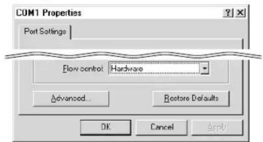
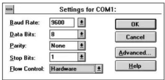
For the driver's port setting, set Flow control to [Hardware.]
For more information about other communication parameters, see "About the Settings for Communication Parameters."
Setup Screen for Windows 95
Setup Screen for Windows 3.1
Selecting the Instruction Set
If you're using the driver for the DXY-1350A/1150A, select RD-GL I as the instruction set. See "DIP Switches" for information on how to make this setting.
Outputting Data from an MS-DOS-based Program
When outputting data from a program, make the settings for the values described below.
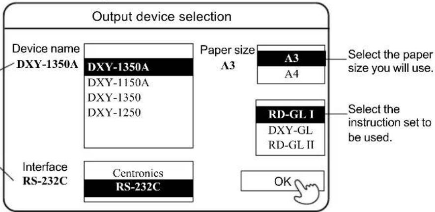
Sample Application Software Output Device Selection Screen
Select DXY-1350A, or DXY-1150A. If these selections are not available, choose any model in the DXY series. Also, if RD-GL II has been selected as the instruction set, choose either the DPX series, GRX series, or GSX series.
Select either the parallel (Centronics) or the serial (RS-232C) interface. Choose the one that the host computer and the DXY are connected by.
Settings for Communication Parameters
Using a serial (RS-232C) cable to connect the DXY with the computer enables the Auto-Protocol function, which makes it unnecessary to set communication parameters on the DXY.

About Auto Protocol
Because the DXY can automatically determine communication parameters, plotting can be carried out simply by downloading the plot data from the computer.
In order for the parameter settings to be made automatically, make sure that DIP switch [SW2-8] on the back of the machine is set to [AUTO.]
Also, if the software is changed while in use, turn the power to the DXY off and then on again to enable the Auto Protocol function to make the automatic determination of the communication parameters.
Communication parameters can also be set without using Auto-Protocol, by follow the method described below.
- Setting DIP switch [SW2-8] to "FIX" disables the Auto-Protocol function. The parameters in effect when this is done are a baud rate (serial transmission rate) of 9600, using and 7-bit data length with EVEN parity checking and one stop bit.
- Auto-Protocol can also be disabled by switching on the power while holding down a position key and the [ENTER] key. The transmission rate is determined by which position key is held down. Communication parameters other than transmission rate are determined by the setting for DIP switch SW 2-8.
* These settings are lost when the power is switched off, and must be made again after powerup.
Setting the baud rate
| 1200 | Turn on the power while holding down the ▶ and ENTER keys. |
| 2400 | Turn on the power while holding down the ▼ and ENTER keys. |
| 4800 | Turn on the power while holding down the ▶ and ENTER keys. |
| 9600 | Turn on the power while holding down the △ and ENTER keys. |
Setting communication parameters other than baud rate
DIP switch [SW 2-8] set to "AUTO":
8-bit data length, no parity, 1 stop bit
DIP switch [SW 2-8] set to "FIX":
7-bit data length, EVEN parity, 1 stop bit
After Plotting
1. Remove the paper.
DXY-1350A: Press the [PAPER HOLD] key to release the electrostatic adsorption and remove the paper.
DXY-1150A: Remove the paper clip, release the metal strips, and remove the paper.
2. Turn off the DXY.
Switch off the power to the DXY. If the plotter will not be used for a long time, the electrical cord should also be unplugged.
3. Remove the pens.
Remove all pens from the pen stock. Cap and store the pens after use.
Care and Maintenance
NOTICE
Be sure to turn off the power to the DXY before cleaning.
Never attempt to oil or lubricate the mechanism.
The drawing board for the DXY-1350A is an electrostatic pad. When cleaning the drawing board, never use water, silicone cloth, neutral detergent, solvent, or chemically-treated cloth. Such materials can permanently degrade the board's electrostatic adhesive force.
Cleaning the Main Unit
If the unit becomes dirty, wipe gently using a cloth moistened with water or anhydrous alcohol.
Cleaning the Drawing Board
Gently wipe with a soft cloth. If soiling is severe or the adsorptive force of the drawing board is weak (DXY-1350A only), wipe gently using a cloth moistened with ethyl alcohol. The DXY-1350A use an electrostatic adsorption drawing board, which must never come in contact with water, neutral detergents, solvents, silicone cloth, or any other type of chemically treated wiper cloths, as these will irrevocably diminish the electrostatic adsorptive force.
Cleaning the Pen Cap Rubbers
Ink buildup on the pen cap rubbers may soil plots. Remove the pen cap rubbers and wash with water. Replace them on the pen stock after allowing to dry completely (out of direct sunlight).
Explanation of Functions and Operation
The DXY has a range of functions that can be performed using the keys on the control panel. This section describes how to use these functions.
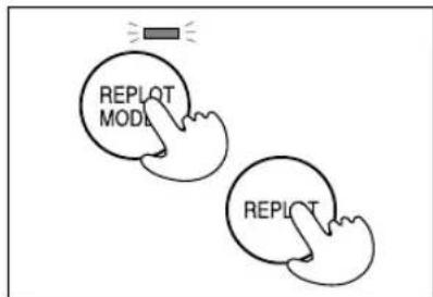
< Replotting (DXY-1350A Only) >
- Before downloading the plot data, press the [REPLOT MODE] key.
The REPLOT MODE LED lights up. - Use the computer software to download the plot data.
- Load a sheet of paper and press the [REPLOT] key.
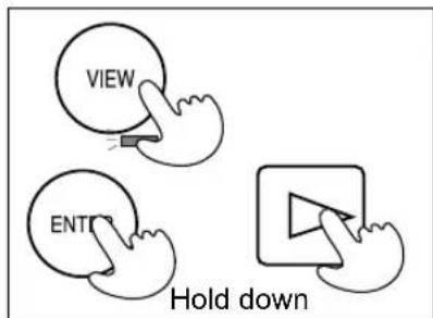
< Erasing Data in the Plotter >
- Press the [VIEW] key.
The pen carriage moves to the upper right of the main unit and stops. - While holding down the [ENTER] key, press the ▶ key.
flowchart
graph TD
    A["REPLOT MODE"] --> B["REPLOT"]
    style A fill:#f9f,stroke:#333
    style B fill:#f9f,stroke:#333

< Stopping a Plot >
- Press the [VIEW] key.
The pen carriage moves to the upper right of the main unit and stops. - Use the computer software to stop sending plot data to the DXY.
- While holding down the [ENTER] key, press the ▶ key.
Plot data remaining in the plotter is deleted.

< Setting Scaling Points ( P1 and P2 ) >
- Use the ▶, ▶, △, ▼ and [FAST] keys to move the pen carriage to the position for setting P1 or P2.
- While holding down the [ENTER] key, press the [P1] or the [P2] key.
< Enabling the Non-buffer Mode >
In the Non-buffer mode, data downloaded from the computer is plotted simultaneously, with no data stored in the buffer within the DXY. This can be handy when debugging a program or testing connections.
- Turn on the power while holding down the ▶ key.


< Enabling the List Mode >
In the List mode, data downloaded from the computer is printed as-is, without processing. This is handy for confirming program content.
- Load paper and a pen (pen No. 1).
- Turn on the power while holding down the [VIEW] key. The pen carriage grasps the pen, moves to the upper left, and awaits data from the computer.
flowchart
graph TD
    A["REPLOT MODE"] --> B["REPLOT"]
    style A fill:#f9f,stroke:#333
    style B fill:#f9f,stroke:#333
Pens
This section describes the pens optionally available for use with the DXY, as well as the DXY's pen-related functions. Compatibility exists for pens and paper. Please refer to the information contained here to select combinations with good compatibility.
By selecting optimum conditions for the pen and paper that are used, the DXY can achieve more accurate plots.
OHP Mode ( Pen speed is controlled at 100 mm (13-15/16")/sec.)
Select this mode when using standard ceramic pens to make plots on OHP transparency sheets.
Turn on the power while holding down the [FAST] key.
Ink Pen Mode ( Pen speed is controlled at 100 mm (13-15/16")/sec.)
Use this mode when plotting with MPP pens or refillable ink pens.
Turn on the power while holding down the key on the control panel.
Cutting Mode (Cutting Speed Controlled at 10 mm (3/8")/sec)
This mode is selected when using the DXY to carry out cutting. Use the DIP switches on the back of the machine to set the cutting offset, then turn on the power to the unit. (See "DIP Switches" for details on the cutting function.)
Setting Pen Speed (DXY-1350A Only)
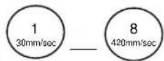
While holding down the [PEN SPEED] key, press any one of the [PEN SELECT] keys from 1 to 8. The chart below shows the pen speeds that can be set with these keys. This function is handy when the optimum speed for the pens being used is known. Pen speed is set to the same value for all pens.
| oNneP | 1 | 2 | 3 | 4 | 5 | 6 | 7 | 8 |
| deepSneP | 30 mm/sec 3/16" | 40 mm/sec 9/16" | 60 mm/sec 2-3/8" | 90 mm/sec 3-9/16" | 120 mm/sec 4-3/4" | 160 mm/sec 6-5/16" | 220 mm/sec 8-11/16" | 420 mm/sec 16-9/16" |
| OHP Mode | 30 mm/sec 3/16" | 40 mm/sec 9/16" | 60 mm/sec 2-3/8" | 90 mm/sec 3-9/16" | 100 mm/sec 3-15/16" | 100 mm/sec 3-15/16" | 100 mm/sec 3-15/16" | 100 mm/sec 3-15/16" |
| rkeRo | 30 mm/sec 3/16" | 40 mm/sec 9/16" | 60 mm/sec 2-3/8" | 90 mm/sec 3-9/16" | 120 mm/sec 4-3/4" | 160 mm/sec 6-5/16" | 200 mm/sec 7-7/8" | 200 mm/sec 7-7/8" |
Changing Maximum Plotting Speed
The DIP switches on the back of the DXY can be used to change the maximum plotting speed. When shipped from the factory, maximum plotting speed is set at 420 mm (16-9/16")/sec (all directions), but when set to [FAST], maximum plotting speed is 600 mm (23-5/8")/sec (45° orientation).
Pen Type Switch
The pen type switch on the side of the main unit can be used to select [Long] or [Short] to match the pen holder in use. The descriptions of the different pens that are available also list the type to be set, so be sure to select the appropriate pen type.
Auto Pen-up and Auto Pen-return Functions
To prevent ink from running or blotting the paper, the DXY features an Auto Pen-up function, which automatically lifts the pen during plotting when approximately three seconds elapse with no data received from the computer. Moreover, is approximately 50 seconds pass with no plot data received, the Auto Return function automatically returns the pen from the carriage to the pen stock. Because there is a pen cap rubber fitted into the pen stock, this can prevent the pen tip from drying out.
Standard Ceramic Pen
Features
The pen tip is a ceramic tube, with ink flowing through it to form the line
Because pen tip diameter is uniform, line thickness is uniform from start until the ink runs out
Pen widths of 0.25 mm (0.00984"), 0.35 mm (0.0138"), 0.50 mm (0.50 mm), and 0.70 mm (0.0276") are available, allowing use for plots or business graphics.
Water-soluble ink available in eight colors (black, red, blue, green, orange, pink, brown and purple)
NOTE
Because these are dye-based inks, plots made with these pens will fade if left exposed to sunlight for long periods. Store plots made using these pens out of direct sunlight.
| Pen cap rubber orientation | Plotting distance (with our standard paper) |
 | 0.25 mm : 2000 m(0.00984":78740")0.35 mm : 1300 m(0.0138" :51181")0.50 mm : 700 m(0.0197" :27559")0.70 mm : 400m(0.0276" :15748") |
| Applicable paper | |
| High-quality paper, tracing paper | |
| Pen type | Short |
Water Based Fiber Tipped Pen
Features
Excellent coloration for colorful illustrations
Comes in eight colors (black, red, blue, green, brown, purple, pink, orange), and two pen tip thicknesses (0.3 mm (0.0118") and 0.6 mm (0.0236"))
NOTE
Long-term use will cause the pen tip to wear, causing a gradual increase in line width.
Because these are dye-based inks, plots made with these pens will fade if left exposed to sunlight for long periods. Store plots made using these pens out of direct sunlight.
| Pen cap rubber orientation | Plotting distance (with our standard paper) |
 | 0.3 mm : 400 m(0.0118":15748")0.6 mm : 300 m(0.0236" :11811") |
| Applicable paper | |
| High-quality paper, coated paper, tracing paper water based OHP film | |
| Pen type | Short |
32 Color Plotter Pens
Features
Variety of colors and shades for colorful expression
Optimum for illustrations, graphs and graphics
Fiber pen tip for simple use
Two pen tip thicknesses - 0.3 mm (0.0118") and 0.6 mm (0.0236")
Following pen colors available:
| Pen cap rubber orientation | Plotting distance (with our standard paper) |
 | 0.3 mm : 400 m(0.0118":15748")0.6 mm : 300 m(0.0236 :11811") |
| Applicable paper | |
| High-quality paper, coated paper, tracing paper water based OHP film | |
| Pen type | Short |
| Black | Brown | Red | Yellow | Green | Blue | Violet | |
| Dark Brown | Mahogany Poppy Red | Golden Yellow | Forest Green Cobalt Blue Dark Purple | Purple | |||
| Grey Pine | Orange Lime Green | Kelly Green Sky | Blue Mauve | Rose Pink | |||
| Warm Grey | Beige | Peach | Lemmon Lime | Olive Green | Ice Blue | Turquoise | |
NOTE
Long-term use will cause the pen tip to wear, causing a gradual increase in line width.
Because these are dye-based inks, plots made with these pens will fade if left exposed to sunlight for long periods. Store plots made using these pens out of direct sunlight.
Thick Water Based Fiber Tipped Pen
Features
Thick water-based fiber tipped pen draws a 2 mm thick line Comes in eight colors (black, red, blue, green, orange, pink, brown, purple)
Optimum for advertising and illustration, because large areas can be colored quickly
NOTE
Plots made with these pens will fade if left exposed to sunlight for long periods. Store plots made using these pens out of direct sunlight.
| Pen cap rubber orientation | Plotting distance (with our standard paper) |
 | 2 mm : 100 m(1/16":3937") |
| Applicable paper | |
| High-quality paper, coated paper, tracing paperWater based OHP film | |
| Pen type | Short |
MPP Pen
Features
No need to refill ink, and maintenance much simpler than refillable ink pens.
Plots sharp, attractive lines, with no change in line thickness or ink flow even over long periods of time.
Non-refillable ink pens come in paper and film types. Select the ink pen appropriate for the media you will be using.
When the film ink pen is used on film, the output can be erased with a commercially-available drafting ink eraser.
When the paper ink pen is used on tracing paper, the output can be erased with a commercially available ink eraser (unless paper moisture absorption is high).
| Pen cap rubber orientation | Plotting distance (with our standard paper) |
 | 0.25 mm : 2500 m(0.00984":98425")0.35 mm : 1800 m(0.0138" :70866") (for paper)0.50 mm : 1400 m(0.0197" :55118")0.70 mm : 800 m(0.0276" :31496") |
| Applicable paper | |
| For paper: High-quality paper, tracing paperFor film: Drafting film | |
| Pen type | Long |
Refillable Ink Pen
Features
The same pen can be refilled and used any number of times.
Plots sharp, attractive lines, with no change in line thickness or ink flow even over long periods of time.
Refillable ink pens come in paper and film types. Select the ink pen appropriate for the media you will be using.
When the film ink pen is used on film, the output can be erased with a commercially-available drafting ink eraser.
When the paper ink pen is used on tracing paper, the output can be erased with a commercially available ink craser (unless paper moisture absorption is high).
| Pen cap rubber orientation | Plotting distance (with our standard paper) |
 | 0.35 mm: 300 m(0.0138":11811")Pen tip will wear out in 6000 m (236220") to 10000 m (393700") of travel |
| Applicable paper | |
| For paper: High-quality paper, tracing paperFor film: Drafting film | |
| Pen type | Long |
Paper
This chapter describes the optional paper that can be used with the DXY. Refer to the table below in paper selection.
| Paper type | Characteristics | Compatible pens | TanoisnemiDyibats |
| High-quality paper | This is the most economical white paper. It tends to contract and expand fairly easily, and ink will spread slightly, making it inappropriate for applications requiring high precision. | ○ Refillable ink pen for paper○ reprospWPO 32 color plotter pens◎ Water based fiber tipped pen○ Thick water based fiber tipped pen○ Standard Ceramic pen | × |
| expC | Whiteness is higher than high-quality paper.This paper shows minimal contraction or expansion due to changes in environmental factors such as humidity. | ○ Water based fiber tipped pen○ Thick water based fiber tipped pen◎ 32 color plotter pens | × |
| Trading paper | Common natural type trading paper.Suited to blueprints. Ink pen is the best pen .epyt | ◎ Refillable ink pen for paper◎ reprospWPO 32 color plotter pens○ Water based fiber tipped pen○ Thick water based fiber tipped pen○ Standard Ceramic pen | × |
| mlifgnfa | Polyester film, with a matte finish on both sides. Has low expansion and contraction, and Shows small change over time, making it optimum for jobs where precision is essential. Use optional ink pens for film. | ◎ Refillable ink pen for film◎ mlifrMPP | ◎ |
| Water bas dOHP film | This is transparent film for use with overhead projector (OHP) devices. | ◎ 32 color plotter pens | ◎ |
| Oil basedOHP film | ◎ Oil based fiber tipped pen | ◎ |
◎Optimum ○Good
■ Paper expands and contracts by absorbing the moisture in the air.
Always plot after getting the paper accustomed to the ambient temperature and humidity. This optimum time will vary with the specific paper type, but generally 30 to 60 minutes after removal from the paper bag is appropriate.
■ Oil on the paper surface may cause poor performance
Take care when loading the paper to prevent transfer of oils or dirt from your hand to the paper surface.
Plot quality and paper
Plot quality changes with the following conditions:
| Condition | Effect |
| Ambient temperature and humidity | Paper expansion and contraction causes offset and ink blotting |
| Pen speed | The line will be faint if the pen speed is too high |
| Pen force | Pen and paper will be damaged if set too high, and line will be faint is set too low |
| Paper type | Moisture absorption characteristics and surface roughness will affect line darkness, coloration and pen clogging. |
When using paper not supplied by Roland DG Corp., observe the following points in making your selection:
■ Does the ink work well with the paper? (moisture absorption characteristics, coloration)
■ Is the ink faint? (at the rated pen speed)
■ Does the ink spread? (line thickness should not change with time)
■ Speed of drying (If one line crosses another, ink should not mix)
■ Does pen clog?
■ Other factors such as paper strength, etc.
Plotting Area
The maximum size of the plotting area varies according to the selected instruction set and operation steps, even when using the same size of paper. For an explanation of how to load and position paper, see "Loading the Paper" on pages 8 and 9.
● Size-reduced Plotting
The settings of the DIP switches on the back of the main unit of the DXY can be changed to reduce plot size and make ISO A0, A1, and A2-size plots on A3-size paper (or ANSI E, D, and C-size plots on ANSI B-size paper). This function is only effective when RD-GL II is selected as the instruction set and paper size is set at ISO A3 (or ANSI B) using the DIP switches. For details, see the plotting areas for size-reduced plotting that are given on the following page.
- Expand Mode
The DIP switch settings of the DXY can be used to set the plotting area. When DXY-GL or RD-GL I has been selected for the instruction set and the Expand mode is turned on, the size of the expanded plotting area matches ANSI B and ISO A3. When RD-GL II is chosen, the size of the plotting area when expanded varies according to paper size. The table below shows the size of the plotting area when the Expand mode is enabled.

- RD-GL I, DXY-GL (1 step/0.025 mm)
| czisrcpaP | gnittolpmumixaM | acagnittolpmumixaM | sgnithatiwsPID | |||
| )mm(aera) | ) setanid | drooc(SW16/1) | SW1-2 | SW1-5 | ||
| OSI3 | × 596704"8/7-51 | 16158, 1104061/31-01 | OFF | OFF | OFF | |
| OSI4 | × 620.89× "61781-71-01 | 11040, 7721 | OFF | ON | OFF | |
| BIAN | × 624.95× "61781-0461 | 16640, 10365 | ON | OFF | OFF | |
| AIAN | × 520.99× "61781-73-01 | 10365, 7962 | ON | ON | OFF | |
| ANDE | × 8.792× "61/17-11 | 17272, 11880 | Varies according to paper size | ON | ||
● DXY-GL (1 step/0.1 mm)
| ezisrepaP | gnitolpmixaM | agnittolpmixaM | sgnithetals | ||
| )maora | )setanidroto(SW1-1 | SW1-2 | SW1-5 | ||
| OSA3 | × 9.602"8/7-51 | 4039, 276061/31-01 | OFF | OFF | OFF |
| OSA4 | × 6.791× "61/8/31-01 | 2760, 1930 | OFF | ON | OFF |
| BIAN | × 6.952× "61/8/31-01 | 4160, 2591 | ON | OFF | OFF |
| AISNA | × 0.992× "61/8/31-01 | 2591, 1990 | ON | ON | OFF |
| ANDE | × 8.792× "61/17/31-01 | 4318, 2970 | Varies according to paper size | ON | |
- RD-GL II
| ezispaP | Maximum plotting area (mm) / (inch) | Maximum plotting area )setinoc | DIP switch settings | ||
| SW1-1 | SW1-2 | SW1-5 | |||
| SD A3 | 09 26(15-5/16" × 10-1/2") | ±7800, ±5340 | OFF | OFF | OFF |
| EXPAND | 02 29(16-1/2" × 11-11/16") | ±8400, ±5940 | ON | ||
| SD A4 | 26 08(10-1/2" × 7-1/16") | ±5340, ±3600 | OFF | ON | OFF |
| EXPAND | 29 01(11-11/16" × 8-1/4") | ±5940, ±4200 | ON | ||
| ANSB | 401.8 × 249.4(15-13/16" × 9-13/16") | ±8036, ±4988 | ON | OFF | OFF |
| EXPAND | 431.8 × 279.4× "71"1 | ±8636, ±5588 | ON | ||
| ANSA | 249.4 × 185.9(9-13/16" × 7-5/16") | ±4988, ±3718 | ON | ON | OFF |
| EXPAND | 279.4 × 215.9× "1"8 | ±5588, ±4318 | ON | ||
● Plotting areas for size-reduced plotting
| edoMlamroN NOdnapxE | ||||
| Paper | Paper size | Size-reduced plotting area | Paper S1ze | Size-reduced plotting area |
| OSA | 1159 mm × 811 mm(45-5/8" × 31-7/8")(-23180, -16220) (23180, 16220) | 390 mm × 267 mm(15-5/16" × 10-1/2")(When reduced to ISO A3 size) | 1189 mm × 841 mm(46-3/4" × 33-1/16")(-23780, -16820) (23780, 16820) | 420 mm × 297 mm(16-1/2" × 11-11/16")(When reduced to ISO A3 size) |
| OSA | 811 mm × 564 mm(31-7/8" × 22-3/16")(-16220, -11280) (16220, 11280) | 841 mm × 594 mm(33-1/16" × 23-3/8")(-16820-, 11880) (16820, 11880) | ||
| OSA | 564 mm × 390 mm(22-3/16" × 15-5/16")(-11280, -7800) (11280, 7800) | 594 mm × 420 mm(23-3/8" × 16-1/2")(-11880, -8400) (11880, 8400) | ||
| EISNA | 1087.6 mm × 833.6 mm(42-13/16" × 32-13/16")(-21752, -16672) (21752, 16672) | 401.8 mm × 249.4 mm(15-13/16" × 9-13/16")(When reduced to ANSI B size) | 1117.6 mm × 863.6 mm(44" × 34")(-22352, -17272) (22352, 17272) | 431.8 mm × 279.4 mm(17"× 11")(When reduced to ANSI B size) |
| DISNA | 833.6 mm × 528.8 mm(32-13/16"×20-13/16")(-16672, -10576) (16672, 10576) | 863.6 mm × 558.8 mm(34"× 22")(-17272, -11176) (17272, 11176) | ||
| CISNA | 528.8 mm × 401.8 mm(20-13/16" × 15-13/16")(-10576, -8036) (10576, 8036) | 558.8 mm × 431.8 mm(22" × 17")(-11176, -8636) (11176, 8636) | ||
- Refer to the above chart when performing size-reduced plotting. Coordinate values are given beneath the indications in millimeters.
- When any member of the DPX Series has been selected as the output device for the computer, the position of the origin point differs from the DXY. For this reason, data outside the coordinates is not plotted when size-reduced plotting is carried out.
DIP Switches
* DIP switches settings must be made only when the power is turned off.
The DIP switches on the back of the main unit can be used in various combinations to enable a variety of plotting conditions. Please change these settings to match your needs. These are all set to OFF when the DXY-1350A/1150A is shipped from the factory.

SW 1-1 ISO or ANSI
SW 1-2 Paper size
SW 1-1 selects either ANSI or ISO size. SW 1-2 selects ISO A3 or A4 (ANSI B or A) size paper.
SW 1-3 and -4 Size-reduced plotting
Enables plots for ISO A0, A1, or A2 paper size to be reduced in size for plotting on ISO A3-size paper. Change the switch settings to match the original size. Size-reduced plotting is enabled only when [A3 B] is selected with SW 1-2 and [RD-GL II] is chosen using SW 2-9 and -10.
SW 1-5 Expanded plotting area
Set this switch to ON when an expanded plotting area is desired. For details, see "Plotting Area".
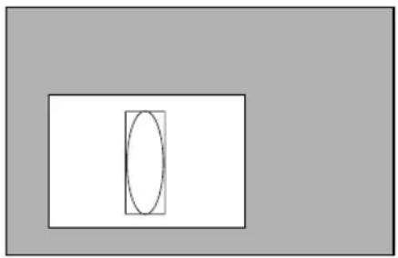
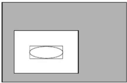
SW 1-6 Plot rotation
When this switch is set to ON, the normal plot orientation is rotated 90^ .
natural_image
Simple geometric diagram with a rectangle containing an oval and a vertical line inside (no text or symbols)When OFF
natural_image
Simple geometric diagram with a rectangle containing an oval, set against a gray background (no text or symbols)When ON
SW 1-7 Plotting speed
This selects plotting speed. When shipped from the factory, this is set to [NORMAL], for a maximum plotting speed of 420 mm/sec in all directions. When [FAST] is selected, maximum plotting speed is set at 600 mm/sec (45° orientation).
SW1-9, -10 Performing Cutting
With the purchase of the optional Blade Holder Set (DXY-BHS), the DXY can be used to cut special sheets. In order to for corners to be cut accurately, the tip of the blade requires an offset. This switch is used to set the appropriate offset value for the blade. When using the blades included in the Blade Holder Set, this should be set to 0.25 mm.
Cautions When Performing Cutting
- Make sure that the installation of the DXY is flat and level.
- The DXY cannot be used to cut fluorescent or thick sheets.
- Pen changing is not performed when in the cutting mode. Be sure that the blade holder is installed in the pen carriage.
- When carrying out cutting, be sure to spread out a cutting-use protective pad to prevent damage to the drawing board.
- When cutting, use cellophane tape to secure the sheet and cutting-use protective pad in place. Because the metal plates and paper clips for the DXY-1150A make strike and damage the blade during cutting, use of these should be avoided.
SW 2-1 to -4 Character set selection
The DXY has 19 character sets, and this selects the one enabled when power is turned on. See "Character Sets" for a list of available character sets.
SW 2-8 Auto Protocol function
Set this to [AUTO] for automatic determination of communication parameters. When set to [FIX], communication parameters are a bit rate of 9,600 baud, even parity, data length of 7 bits, and one stop bit.
SW 2-9 and -10 Instruction set selection
Make this setting to correspond to the instruction set in use. When using DXY-GL, set the operation step at 1 step/0.1 mm (0.00394") or 1 step/0.025 mm (0.000984").
When performing output with the driver included with the DXY-1350A/1150A, select RD-GL I.
What to Do If...
If the DXY Doesn't Run...
Is the DXY power on?
Turn on the power.
Is the DXY operating incorrectly
Follow the procedure described under "Self-testing" to execute a self-test. If the self-test finds a problem, check to make sure that the problem is not due to the computer or the software.
- Computer
Is the computer set up correctly?
Check the following items:
- DIP switches - Memory switches - Interface board - Other
Read the computer user's manual and set it up correctly.
- Connection cable
Are the computer and the plotter linked with the right cable?
The type of cable you need is determined by your computer and the software you are using. Even if the computer is the same, running different software may require a different cable. Use the cable specified in your software.
Is the cable making a secure connection?
Connect securely.
- Software
Is the OS set up correctly?
Check the following items:
- Output port selection - Output device selection - Output port open - Other
Check the OS user's manual and set it up correctly.
Are the application software settings correct?
Check the following items:
- Output device specification (select a plotter name that matches the instruction system. If the wrong plotter is selected an incorrect instruction may be output, resulting in an error).
- Communication parameters
- Other
Check the software user's manual and set it up correctly.
Pen is not grasped or returned normally
Is the pen loaded correctly?
Please refer to "Loading the Pens" to install the pens correctly.
Is the pen cap rubber installed so that it is oriented correctly?
Install the pen cap rubber correctly as described.
Plot quality is poor
Is the paper of the recommended type?
Refer to the chart shown in "Paper" and load a paper type that is suitable for the DXY.
Is the paper loaded correctly?
Read “Loading the paper”, and load the paper correctly.
Do the pens match the paper type?
Read “Pens” and “Paper”, and use an appropriate type of pen.
Are the DIP switches set for the Cutting Mode?
When plotting with a pen, be sure to set DIP switches SW1-9 and SW1-10 to OFF.
If DIP switches SW-1-9 and SW-1-10 are not both set to OFF, the DXY remains in the Cutting Mode. Attempting pen plotting while the Cutting Mode is enabled will result in poor output quality for text, circles, and other short lines. This is because the DXY is performing processing that enables a blade to cut the cutting sheet smoothly.
Plot size is wrong
If application software is being used, is the setting for the output size correct?
Read the operation manual for the software you are using, and make the correct settings for the plot size.
Are the DIP switch settings correct?
The DXY can reduce plot size to print ISO A0, A1, or A2-size plot data on A3-size paper (or ANSI E, D, or C-size data on B-size paper). Size-reduced plotting cannot be performed on A4-size paper (or ANSI A-size paper). To make size - reduced plot, see "Plotting Area" and "DIP Switches".
Plotting position and range are different
If application software is being used, is the setting for the output position and range correct?
Read the operation manual for the software you are using, and make the correct settings for the output position and range.
Is the same instruction set selected for the computer and the DXY?
The settings for the computer and the DXY do not match. If you have selected either our DPX series, GRX series, or GSX series for the computer, select RD-GL II for the DXY. If our DXY series has been selected, choose either RD-GL I or DXY-GL for the DXY. In particular, when DXY-980A/880A has been selected, the setting for DXY-GL/0.1 mm (0.00394") is made. See "DIP Switches" for details.
Adsorptive force is poor (DXY-1350A only)
Did your remove the protection vinyl on the drawing board?
The protection vinyl could reduce adsorptive force, and you should remove it before use.
Serial data is not received correctly when using Auto-Protocol
Serial data may not be received correctly in cases such as these:
- Reception of serial data is started while in View mode
- Reception of serial data is started while the pen carriage is in motion because of a control-panel operation
Also, the unit may be unable to determine the protocol when the amount of serial data being input is small (approximately ten characters or less, depending on the header data). The pen carriage does not move and the control panel is inoperative until the protocol is determined.
If this happens, go to the "Sending Plotting Data" section and refer to "Settings for Communication Parameters" to make fixed settings for the serial port's baud rate and format.
List of DXY-GL Related Instructions
The list provides the instruction compatibility of the DXY-1350A/1150A with the DXY-GL I instruction system and the parameters of these instruction.
○: Compatible.
●: Ignored.
×: Incompatible.
| Instructions | Compatibility | Format | Parameter | Range [Default value] |
| A Circle center A x,y | x,y Center | coordinate : -32768.0000—+32767.4999 | ||
| B Line scale B 11 Pitch of dotted line : 0—32767.4999 [80] | ||||
| C Circle | ○ | C x,y,r,ø1,ø2(ød) | x,y Center coordinater Radiusø1 Start angleø2 End angleød Resolution | :-32768.0000—+32767.4999:-32768.0000—+32767.4999:-32767°—+32767°:-32767°—+32767°:1.0000°—179.9999° [5°] |
| D Draw | ○ | D x1,y1(,x2,y2,...,xn,yn) | xn,yn Absolute coordinate | :-32768.0000—+32767.4999 |
| E Relative circle | ○ | E r,ø1,ø2(ød) | r Radiusø1 Start angleø2 End angleød Resolution | :-32768.0000—+32767.4999:-32767°—+32767°:-32767°—+32767°:1.0000°—179.9999° [5°] |
| G A + Circle | ○ | G r,ø1,ø2(ød) | r Radiusø1 Start angleø2 End angleød Resolution | :-32768.0000—+32767.4999:-32767°—+32767°:-32767°—+32767°:1.0000°—179.9999° [5° ] |
| H Home | ○ H | none | ||
| I Relative draw | ○ | Δx1,Δy1(,Δx2,Δy2,...,Δxn,jyn) | Δxn,Δyn Relative coordinate | :-32768.0000—+32767.4999 |
| J Pen change | ○ | J n | n Pen number | :0—8 [1] |
| K A + % | ○ | K n,l1,l2 | n Percentage with respect to 0% of the uppermost partl1 Distance of the end position from the centerl2 Distance of the starting position from the center | :-9101—+9101-32768.0000—+32767.4999:-32768.0000—+32767.4999 |
| L Line type | ○ | L p | p Line type | :-5—+5 [0] |
| M Move | ○ | M x1,y1(,x2,y2,...,xn,yn) | xn,yn Absolute coordinate | :-32768.0000—+32767.4999 |
| N Mark | ○ N | n | n | :1—15 |
| P Print | ○ | P c1c2...cn | cn Character | |
| Q Alpha rotate | ○ | Q n | n Angle(90°) | :0—3 [0] |
| R Relative move | ○ | R Δx1,Δy1(,Δx2,Δy2,...,Δxn,Δyn) | Δxn,Δyn Relative coordinate | :-32768.0000—+32767.4999 |
| S Alpha scale | ○ | S n | n Character size | :0—127 [3] |
| T Hatching | ○ | T n,x,y,d,t | n Slection of types of rectangle and hatchingx,y X axis and Y axis lengthd Spacing between hatchingt Hatching angle :1— | :0—3:-32768.0000—+32767.4999:-32768.0000—+32767.4999 |
| X Axis | ○ | X p,q,r | p Selection of axisq Scale spacingr Number of repetitions | :0 or 1:-32768.0000—+32767.4999:1.0000—32767.4999 |
| Y Curve | ○ | Y m,x1,y1,x2,y2,...,xn,yn | m Selection of curved typexn,yn Coordinate | :0—3:-32768.0000—+32767.4999 |
| _ Relative curve | ○ | _ m,Δx1,Δy1(,Δx2,Δy2,...,Δxn,Δyn) | m Selection of curved typeΔxn,Δyn Relative coordinate | :0—1:-32768.0000—+32767.4999 |
| ^ Call RD-GLI | ○ | ^ [RD-GLI instruction][parameter]....(,[parameter]) [terminator:] | ||
List of RD-GL I Related Instructions
The list provides the instruction compatibility of the DXY-1350A/1150A with the RD-GL I instruction system and the parameters of these instruction.
○: Compatible.
●: Ignored.
× : Incompatible.
| Instruction | Compatibility | Format | Parameter | Range [Default value] | Note | |
| AA | Arc Absolute | ○ | AA x,y,oc(,od); x,y Center coordinate : -32768.0000—+32767.4999 c Center angle : -32768.0000° d Resolution | : +32767.4999°: -32768.0000°—+32767.4999°[5°] | ||
| AF | Advance Full Page | ● | AF; none | |||
| AR | Arc Relative | ○ | AR x, y, c,(nd) ; | x, y Center coordinate c Center angle : -32768.0000° d Resolution | : -32768.0000—+32767.4999+32767.4999°: -32768.0000°—+32767.4999°[5°] | |
| CA | Alternate Character Set | ○ | CA n;CA; | n Character set number | : 0—4,6—9,30—39 | |
| CI | Circle | ○ | CI r(,od) | r Radius d Resolution | : -32768.0000—+32767.4999: -32768.0000°—+32767.4999°[5°] | |
| CP | Character Plot | ○ | CP nx,ny ;CP ; | nx Number of characters in X directionny Number of characters : -128.0000—+127.9999in Y direction | : -128.0000—+127.99998.0000—+127.9999 | |
| CS | Standard Character Set | ○ | CS n;CS; | n Character set number | : 0—4,6—9,30—39 | |
| DC | Digitize Clear | ● | DC; | nonc | ||
| DF | Default | ○ | DF; none | |||
| DI | Absolute Direction | ○ | DI run,rise;DI; | run=0 Vertical printingrise=0 Horizontal printing | : -128.0000—+127.9999[1]: -128.0000—+127.9999[0] | |
| DP | Digitize Point | ● | DP; none | |||
| DR | Relative Direction | ○ | DR run,rise;DR; | run=0 Vertical printingrise=0 Horizontal printing | : -128.0000—+127.9999[1]: -128.0000—+127.9999[0] | |
| DT | Defile Label Terminator | ○ | DT t; | t Label terminator | ||
| EA | Edge Rectangle Absolute | ○ | EA x,y; | x,y Absolute coordinate | : -32768.0000—+32767.4999 | |
| ER | Edge Rectangle Relative | ○ | ER x, y ; | x, y Relative cccordinate | : -32768.0000—+32767.4999 | |
| EW | Edge Wedge | ○ | EW r,øl,øc(,od); | r Radiusøl Start angle c Center angle : -32768.0000° d Resolution | : -32768.0000—+32767.4999: -32768.0000°—+32767.4999°+32767.4999°: -32768.0000°—+32767.4999°[5°] | |
| FT | Fill Type | ○ | FT n,(d,ø));FT; | n Hatching patternd Spacing Angle | : 1—5[1]: 0—32767.4999[(P2-P1) x 0.01]: -32760°—+32760°[0°] | |
| IM | Input Mask | ○ | IM c;IM; | c Error mask valuc | : 0—255[223] | |
| IN | Initialize | ○ | IN; | none | ||
| IP | Input P1 and P2 | ○ | IP P1x,P1y,(P2x,P2y); | P1x,P1y Coordinate of P1P2x,P2y Coordinate of P2 | : -32768.0000—+32767.4999[Depends on the paper size]: -32768.0000—+32767.4999[Depends on the paper size] | |
| IW | Input Window | ○ | IW LLx,LLy,URx,URy; | LLx,LLy Coordinate of lower left cornerURx,URy Coordinate of upper right corner | : -32768.0000—+32767.4999[Depends on the paper size]: -32768.0000—+32767.4999[Depends on the paper size] | |
| LB | Label | ○ | LB c1c2......cn[label terminator] | cn Character string | ||
| LT | Line Type | ○ | LT n,(l);LT; | n Pattern number1 Pitch length | : -128—+127[Solid line]: 0—127.9999%[4%] | |
| NR | Not Ready | ○ | NR; | none | ||
| OA | Output Actual Position | ○ | OA; | none | ||
| Instruction | Compatibility | Format | Parameter | Range [Default value] | Note |
| OC Output Commanded OC; none Position | ○ | ||||
| OD Output Digitize OD; none | ● | ||||
| OE Output Error OE; none | ○ | ||||
| OF Output Factor | ○ | OF; | none | 40,40[TERM](10,10[TERM]: DX Y-GL 0.1mm mode) | |
| OH Output Hard-Clip Limits OH; none | ○ | ||||
| OI Output Identification OI; none 1350(DXY-1350A) | 1150(DXY-1150A) | ||||
| OO Output Option Parameter | ○ | OO; | none | 0,1,0,0,1,0,0,0 | |
| OP Output P1 and P2 | ○ OP; none | ||||
| OS Output Status | ○ | OS; none | |||
| OW Output Window | ○ | OW; | none | ||
| PA Plot Absolute | ○ | PA x1,y1(x2,y2......,xn,yn); PA; | xn,yn Absolute coordinate | :-32768.0000—+32767.4999 | |
| PD Pen Down | ○ | PD x1,y1(x2,y2......,xn,yn); PD; | xn,yn Coordinate | :-32768.0000—+32767.4999 | |
| PG Page Feed | ○ | PG (n); PG; | n | :-32768—+32767 | |
| PR Plot Relative | ○ | PR x1,y1(x2,y2......,xn,yn); PR; | xn,yn Relative coordinate | :-32768.0000—+32767.4999 | |
| PS Paper Size | ○ | PS s; | s Paper size | :0—127 | 0—3 -> A34—127 -> A4 |
| PT Pen Thickness | ○ | PT d; PT; | d Pen thickness | :0.1—0.5 [0.3 ] | |
| PU Pen Up | ○ | PU x1,y1(x2,y2......,xn,yn); PU; | xn,yn Coordinate | :-32768.0000—+32767.4999 | |
| RA Shade Rectangle Absolute | ○ | RA x,y; | x,y Absolute coordinate | :-32768.0000—+32767.4999 | |
| RO Rotate Coordinate System | ○ | RO n; RO; | n Rotate angle | :0.90 [0] | |
| RR Shade Rectangle Relative | ○ | RR x,y; | x,y Relative coordinate | :-32768.0000—+32767.4999 | |
| SA Select Alternate Set | ○ | SA; none | |||
| SC Scaling | ○ | SC Xmin,Xmax,Ymin,Ymax; SC; | Xmin P1 user X coordinateYmin P1 user Y coordinateXmax P2 user X coordinateYmax P2 user Y coordinate | :-32768.0000—+32767.4999:-32768.0000—+32767.4999:-32768.0000—+32767.4999:-32768.0000—+32767.4999 | |
| SI Absolute Character Size | ○ | SI w.h; SI; | w Character widthh Character height | :-128.0000—+127.9999 cm:-128.0000—+127.9999 cm | A3-> "SI0.29,0.38;"A4-> "SI0.19,0.27;" |
| SL Character Slant | ○ | SL tanø; SL; | tanø Character slant | :-128.0000—+127.9999 [0°] | |
| SM Symbol Mode | ○ | SM s; SM; | s Character or symbol | ||
| SP Select Pen | ○ | SP n; SP; | n Pen number | :0—8 [0] | |
| SR Relative Character Size | ○ | SR w.h; SR; | w Character widthh Character height | :-128.0000—+127.9999% [0.75% ]:-128.0000—+127.9999% [1.5% ] | |
| SS Select Standard | ○ | SS; | nonc | ||
| TL Tick Length | ○ | TL lp(ln); TL; | lp Tick length in positive directionln Tick length in negative direction | :-128.0000—+127.9999 [0.5%]:-128.0000—+127.9999 [0.5%] | |
| UC User Defined Character | ○ | UC (c),x1,y1,(c),x2,y2...xn,yn); UC; | c Pen control valuexn Number of X gridsyn Number of Y grids | :-128.0000—99,+99—+127.9999:-99—+99:-99—+99 | |
| VS Velocity Select | ○ | VS s; VS; | s Pen speed | :0—127.9999 [42] | |
| WG Shade Wedge | ○ | WG r,ø1,øc(ød); | r Radiusøl Start angleøc Center angleød Resolution | :-32768.0000—+32767.4999:-32768.0000°—+32767.4999°:-32768.0000°—+32767.4999°:-32768.0000°—+32767.4999° [5°] | |
| XT X-Tick | ○ | XT; none | |||
| YT Y-Tick | ○ | YT; none | |||
List of RD-GL II Related Instructions
* 1: - (2 ^23 )—(2 ^23 -1)
* 2: -0— + (2 ^23 -1)
* 3: - (23) — + (2 ^23 -1)
* 4: - (2 ^15 )— + (2 ^15 -1)
The list provides the instruction compatibility of the DXY-1350A/1150A with the RD-GL II instruction system and the parameters of these instruction.
○: Compatible.
●: Ignored.
×: Incompatible.
| Instruc-tion b | Compati-lity | Format | Parameter | Range ([ ]: Default) | Expanation |
| AA AA | x,y,dc(,od); | x,y: Center : *1 | coordinate c : Center angle : *3 d : Chord tolerance : *3 [5°] | ||
| AF AF | ● | None | |||
| AH | ● | AH; | Nonc | ||
| AP | ● | AP n;AP; | n: Pen control value | 0-225 (Decimal fractions are rounded.) | |
| AR | ○ | AR x,y,dc(,od); x,y: Relative | :*1coordinates to the center c : Center angle : *3 d : Chord tolerance : *3 [5°] | ||
| BL | ○ | BL c1c2...cn[label terminator]BL [label terminator] | cn: Character | The maximum character buffer capacity, including control characters (e.g., label terminator) is 150 characters. Characters more than 150 are ignored. | |
| CA | ○ | CA n;CA; | n: Character setnumber | :-1,0-59,70,80,99,101 | •Any character number without the range of *1 results in error (3). If a character number is within that range, it results in error (5) and the instruction is ignored. |
| CC | ○ | CC c ;CC; | c : Center angle | :*3 [5°] | The maximum center angle is 45°. This means that even if specifying a center angle more than 45°, 45° will be set. |
| CI | ○ | CI r(,od) | r: Radius d : Chord tolerance : *3 [5°] | :*1 | |
| CM CM | n1(n2); | n1: Character set | 0-3moden2: Fall back mode | (Decimal fractions are rounded) [0]: 0 or 1(Decimal fractions are rounded) [0] | |
| CP | ○ | CP nx.ny ;CP ; | nx: The number of X-axis directional charactersny: The number of Y-axis directional characters | :*1 (Decimal fractions are rounded): *1 (Decimal fractions are rounded) | If any pen moving distance exceeds 8388607 and also any pen movement to any coordinates exceeding *1, it results in error (3) and the instructions are ignored. |
| CS | ○ | CS n;CS; | n: Character setnumber | :-1,0—59,70,80,99,101 | Any character number without the range of *1 results in error (3). If a character number is within that range, it results in error (5) and the instruction is ignored. |
| CT | ○ | CT n;CT; | n: Chord tolerancemode | : 0 or 1(Decimal fractions are rounded) [0] | |
| DC DC | ● | Nonc | |||
| DF DF | ○ | Nonc | |||
| DI | ○ | DI run,rise;DI; | run: X-axis : *1 [1]directional vectorrise: Y-axisdirectional vector | :*1 [0] | |
| DI. | ○ | DI. n(pc),x1,y1......(pc)......,xn,yn;DL n;DL; | n: Character numberpc: Pen controlxn,yn: Grid : -127—+127coordinate values | :33—126 (Decimal fractions are rounded):-128 (Decimal fractions are rounded)(Decimal fractions are rounded) | |
| DP DP | ● | none | |||
| DR | ○ | DR run,rise; run: X-axisDR; | :*1 [1]directional vctorrise: Y-axisdirectional vector | :*1 [0] | |
| DSDT DT | ○t; t: Label ter-mininator [[ETX] (03h)] | DS s,n;DS; | s: Slot numbern: Character setnumber | :0—1 (RD mode)0—3 (ISO mode)(Decimal fractions are rounded) [0]: -1,0—60,70,80,99(Decimal fractions are rounded) | |
| DV DV | n; n character : 0 or 1 [0]DV; direction (Decimal frac-ions are rounded) | ||||
| EA EA | x,y; x,y: : *1 | Absolute coordinate diagonal to rectangle | |||
| EC EC | n; N●cEC; | ||||
| EP | ○ | EP; | Nonc | ||
| ER ER | x,y; x,y: : *1 | Relative coordinate diagonal to rectangle | |||
| ES | ○ | ES w,(h); | w: Character spacingh: Line spacing | : *1 [0]: *1 [0] | |
| EW EW | r,σ1,oc(,od); r: Radius | : *1ø1: Start angleøc: Center angleød: Chord tolerance | : *3: *3: *3 [5°] | ||
| FP | ○ | FP; | Nonc | ||
| FR FR | ● | None | |||
| FS | ● | FS f,(n);FS; | f: Pen forcen: Pen number | : 1-16: 1-8 [All eight pens] | |
| FT | ○ | FT n,(dl,(s));FT; | n: Patternd: Spacingø: Angle | : 1-6 (Decimal fractions are rounded): *1 [ (P2x-P1x) x 0.01]: *3 [0°] | |
| GM | ○ | GM pl,(dl,(r1,(r2,(r3)));GM; | pl: Polygon bufferdl: Downloadable character bufferr1,r2,r3:Ignored (Always 0) | The minimum, maximum and default values of each buffer are shown in the table below. | If a value other than 0 or less than the min. value is specified, the min. value will be set. If 0 is specified, 4 is set to the polygon buffer, 0 to the downloadable character buffer, and 0 to the pen sort buffer. If a value over the max. value is specified, the max. value will be set. If an odd value is specified, an even value from which 1 is subtracted will be set. |
| GP | ● | GP g,(h,(i,(j)));GP; | g: Group numberh: Pen numberi: Number of pensj: Line length | 1-8 (Decimal fractions are rounded.)1-8 (Decimal fractions are rounded.)[Same as the group number]1-8 (Decimal fractions are rounded.) [1]1-5000(m) [100] | |
| IM | ○ | IM e;IM; | e: Error mask value | : 0-255 (Decimal fractions are rounded) [223] | |
| IN | ○ | IN n;IN; | n: excluding some defaults | : -1 | |
| IP | ○ | IP P1x,P1y,(P2x,P2y);IP; | P1x,P1y: coordinateof P1P2x,P2y: coordinateof P2 | : *1: *1 | |
| IV | ○ | IV s,(t);IV; | s: Slot numbert: Character table | : 0-1 (RD mode)(Decimal fractions are rounded)0-3 (ISO mode)(Decimal fractions are rounded)[0]: 0 or 1 (Decimal fractions are rounded) [0] | |
| IW | ○ | IW LLx,LLy,URx,URy;IW; | LLx,LLy: coordinateat the lower-left corner of a windowURx,URY: coordinateat the lower-left corner of a window | : Maximum plotting area[Maximum plotting area](Follows the panel key setting.) | Even if the parameter exceeds the maximum plotting area when it is within the *1 range, no error occurs. |
| KY KY | k,(f),● | k: KeyKY; f: Function 0-12 | 1-4 | ||
| LB | ○ | LB c1c2,...en[label terminator] | cn: Character | ||
| LO O n; n: Position | In number : 1-9,11-19LO; (Decimal fractions arc rounded) [1] | ||||
| LT Tn(1); m: Pattern number : -6-+6LT; l: 1 pitch length : *2 (%) [4%] | |||||
| NR R; None | N | ||||
| OA | ○ | OA; None | |||
| OC | ○ | OC; | None | X-axis and Y-axis coordinate values that arc output arc up to the forth decimal point and are real numbers within the *1 range. | |
| OD | ● | OD; None | |||
| OE | ○ | OE; None | |||
| OF | ○ | OF; | None | After receiving the OF instruction, the DXY-1350A/1150A always outputs the following values:40,40[TERM] | |
| OH | ○ | OH; None | |||
| OI | ○ | OI; | None | After receiving the OF instruction, the DXY-1350A/1150A outputs as follows:1350 | TERM | DXY-1350A 1150 | TERM | DXY-1150A | |
| OK | ● | OK; None | |||
| OL | ○ | OL; | None | ||
| OO | ○ | OO; | None | Four out of the eight optional parameters in the DXY-1350A/1150A are effective and makes the following integers ready to output.0, 1, 0, 0, 1, 1, 0, 1 [TERM]indicates a buffer that can be set by user.enables the polygon to be filled.indicates a circle or arc command.indicates the availability of pen replacement. | |
| OP OP | ○ | None | |||
| OS OS | ○ | None | |||
| OT | ○ | OT; | None | ||
| OW | ○ | OW; | None | ||
| PA | ○ | PA x1,y1,(x2,y2...,xn,yn);PA; | xn,yn: Absolute coordinate | :*1 | |
| PB | ○ | PB; | None | The maximum capacity of the character buffer is 150 characters. | |
| PD | ○ | PD x1,y1,(x2,y2...,xn,yn);PD; | xn,yn: coordinate | :*1 | |
| PG | ○ | PG (n);PG; | None | ||
| PM | ○ | PM n; | n: Polygon mode | : 0,1,2 [PM0PM2:] | |
| PR | ○ | PR x1,y1,(x2,y2...,xn,yn);PR; | xn,yn: Relative coordinate | :*1 | |
| PS PS f(w);○ | L: The length of frame : *1PS; w: The width of frame : *1 | ||||
| PT | ○ | PT d;PT; | d: Pen tip size | : 0.1-5.0 (mm) [0.3mm] | |
| PU | ○ | PU x1,y1,(x2,y2...,xn,yn);PU; | xn,yn: Coordinate | :*1 | |
| RA | ○ | RA x,y; | x,y: Absolute coordinate diagonal to rectangle | :*1 | |
| RO | ○ | RO n;RO; | n: Rotation angle | : 0,90 [0°] | |
| RR RR | x,y; ○ | x,y: Relative | :*1coordinate diagonal to rectangle | ||
| SA SA; None | |||||
| SC SC | Xmin,Xmax, Ymin Xmin,Ymin: User : *1,Ymax(.type(.left,bottom)); coordinate of P1SC Xmin,Xfactor,Ymin Xmax,Ymax: User : *1,Yfactor,type; coordinate of P1SC; type: Scaling type : 0.1.2 | : 1coordinate of P1: coordinate of P1: left : 0-100 (%)bottom : 0-100 (%)Xfactor: User Xcoordinate of P1Yfactor: User Ycoordinate of P2 | :*1:*1 | ||
| SG SG | g; g;group number : 0-8 [0]SG; | ||||
| SI | ○ | SI w.h;SI; | w: Character widthh: Character height | :*1 (cm) [0.285cm]: *1 (cm) [0.375cm] | |
| SL | ○ | SL tanø;SL; | tanø: Character slant | :*1 [0] | |
| SM | ○ | SM s;SM; | s: Character or symbol | : CHR(33)-CHRS (58),CHR (60)-CHR$ (126)(If no parameter, symbol mode OFF) | |
| SP SP | n; ○ | n: Pen numberSP; | : 0-8 [0] | ||
| SR | ○ | SR w.h;SR; h: Character height | w: Character width:*1 (%) [0.375cm] | :*1 (%) [0.285cm] | |
| SS | ○ | SS; | none | ||
| TL TL | lp(lm); | lp: Tick length in : *1 (%) [0.5%positive directionlm: Tick length innegative direction | :*1 (%) [0.5%] | ||
| UC | ○ | UC (c,)Ééx1,Ééy1((c),Ééx2,Ééy2,...,Ééxn.Éçyn);UC; | c: Pen cotrol valuean: Number ofX-axis directionalmoving unitsyn: Number ofY-axis directionalmoving units | :-8388608--9999,+9999--+8388607:-9998--+9998:-9998--+9998 | The number of allotted units of each font is as follows:Fixed character width font: 48(W) x 64(H)Optimum character width font: 42(W) x 72(H)Normal characters are plotted within the following range. It means that if you define a character so as to be accommodated in there, it becomes the same size as a normal character.Fixed character width font: 32(W) x 32(H)Optimum character width font: 28(W) x 36(H) |
| UF | ○ | UF d1(d2,...d20);UF; Hatching spacing | d1-d20:partition ratio | :*2 | The maximum number of parameter you can set is 20. |
| VS | ○ | VS v(n);VS; | v: Pen speedn: Pen number | : 1-42 cm/sec[Value by automatic pen sensing]: 1-8 [All eight pens] | The pen speed can be set in the unit of 1cm/sec.The parameter range of 1-S388607 is for no error.If the pen speed is set over 42, it will be set at 42.If the pen number is set over 9, the instruction is ignored. |
| WD WD | c1c...cn | en: Character[label terminator]WD [label terminator] | |||
| WG | ○ | WG r,ø1,øc(ød); | r: Radiusø1: Start angleøc: Center angleøl: Chord tolerance | :*1:*3:*3:*3 [5°] | You can input a polygon of up to 250 vertices into the polygon buffer in the state of being initialized. If you, however, input a polygon of vertices more than the buffer capacity, an error occurs. |
| XT | ○ | XT; | None | The default tick length of X-axis is 0.5% of (P2y-P1y) in the positive and negative directions, respectively. | |
| YT | ○ | YT; | None | The default tick length of Y-axis is 0.5% of (P2x-P1x) in the positive and negative directions, respectively. | |
The Specifications of the Interface
Serial Interface (RS-232C)
- Connector
| Name\ang | un | ang | Name | Pin Connection |
| NC | 25 | 13 | NC |  |
| NC | 24 | 12 | NC | |
| NC | 23 | 11 | NC | |
| NC | 22 | 10 | NC | |
| NC | 21 | 9 | NC | |
| DTR | 20 | 8 | NC | |
| NC | 19 | 7 | SG | |
| NC | 18 | 6 | DSR | |
| NC | 17 | 5 | CTS | |
| S.RXD | 16 | 4 | RTS | |
| NC | 15 | 3 | RXD | |
| S.TXD | 14 | 2 | TXD | |
| 1 | FG | |||
Parallel Interface (in compliance with specifications of Centronics)
Connector
| Name\langiS | lanimreT langiS | noitcennoCniP | ||
| reomName | ||||
| CN | 6 | 3 | *HGIH | |
| *HGIH | 5 | D N | ||
| CN | 4 | 3 | N G | |
| DNG | 3 | 3 | NC | |
| *HGIH | 2 | NC H G | ||
| CN | 1 | 3 | G B | |
| GND | 30 | 2 | 1 | +5V 3.3KΩ |
| 29 | 1 | 1 | ||
| 28 | 0 | 1 | ||
| 27 | 9 | 7 | ||
| 26 | 8 | 6 | ||
| 25 | 7 | 5 | ||
| 24 | 6 | 4 | ||
| 23 | 5 | 3 | ||
| 22 | 4 | 2 | ||
| 21 | 3 | 1 | ||
| 20 | 2 | 0 | ||
| 19 | 1 | E | ||
Device control
Device control instructions are used to determine the communication sequence between the plotter and computer through RS-232C interface and/or tell the plotter the current computer state. Among them, some device control instructions set the output specifications of RD-GLI/II instructions.
Each device control instruction is organized with three letters: ESC (1Bh), “.” and one uppercase letter. Device control instructions are of two types: one with parameters and the other without parameters.
Parameters can be omitted. A semicolon “;” is used as a delimiter to separate parameters if they are input in succession. A “;” without parameters means that parameters were omitted.
If parameters are omitted, the default value is set. For a device control instruction with parameters, a terminator needs to be input in order to signify the end of instructions. A colon “:” is used as the terminator which cannot be omitted. Please refer to the following table for device control instructions. Depending on the instruction set that has been selected, some device control instructions may be ignored.
○: Compatible.
●: Ignored.
List of device control instructions
| Instruction | Format | Parameter | Range ([ ] is default) | Explanation | RD-GL I | RD-GL II | ||
| Handshake Instructions | ||||||||
| ESC .BOutput Remaining Buffer Capacity | |ESC|.B | None | Outputs the current remaining buffer capacity. | ○ | ○ | |||
| ESC .MSet Handshake Output Specifications (1) | [ESC].M;P1:Delay time P2:Output trigger character P3:Echo terminator P4:Output terminator P5:Output terminator P6:Output initiator | P1:Delay time P2:Output trigger character P3:Echo terminator P4:Output terminator P5:Output terminator P6:Output initiator | 0—32767(msec) [0(msec)] [0(Sets nothing)] [0(Sets nothing)] [13(|CR|)] [0] [0(Sets nothing)] | Sets handshake output specifications.Note:When you specify some values toand, always set 0 to. When you specify some value to, always set 0 to. | ○ | ○ | ||
| ESC .NSet Handshake Output Specifications (2) | |ESC].N;P1:Intercharacter delay P2—P11 :Xoff character (for Xon/Xoff) Immediate response character (for ENQ/ACK) | P1:Intercharacter delay P2—P11 :Xoff character (for Xon/Xoff) Immediate response character (for ENQ/ACK) | 0-32767(msec) [0(msec)] [All 0(Sets nothing)] | Sets an intercharacter delay, and also an Xoff character for performing the Xon/Xoff handshake. | ○ | ○ | ||
| ESC .HSets ENQ/ACKHandshake Mode1 | |ESC|.H:;P2>;:*****;P1:The number of bytes for data blockP2:ENQ characterP3—P12:ACK character (only whenis set) | P1:The number of bytes for data blockP2:ENQ characterP3—P12:ACK character (only whenis set) | 0-15358(byte) [80(byte)][0(Sets nothing)][All 0(Sets nothing)] | When receiving the ENQ character set by, compares the value set byand the remaining buffer capacity, and returns the ACK character to the host computer when the remaining buffer capacity is larger. The |ESC|.H with no parameter performs a dummy handshake. | ○ | ○ | ||
| ESC .ISet Xon/XoffHandshake andENQ/ACK Hand-shak Mode2 | [ESC].I:;P2>;:*****;P1:Limit of the remaining buffer capacity (for Xon/Xoff)The number of data block bytes (for ENQ/ACK (mode2))P2:ENQ character (for ENQ/ACK (mode2))0(for Xon/Xoff)P3—P12:Xon character(for Xon/Xoff)ACK character (for ENQ/ACK (mode2)) | P1:Limit of the remaining buffer capacity (for Xon/Xoff)The number of data block bytes (for ENQ/ACK (mode2))P2:ENQ character (for ENQ/ACK (mode2))0(for Xon/Xoff)P3—P12:Xon character(for Xon/Xoff)ACK character (for ENQ/ACK (mode2)) | 0-15358(byte) [80(byte)][0(Sets nothing)][All 0(Sets nothing)] | Used for performing the Xon/Xoff handshake and the ENQ/ACK handshake mode 2.The [ESC].I instruction with no parameter performs a dummy handshake. In a dummy hand-shake, always returns the ACK character to the host computer, regardless of the remaining buffer capacity, when receiving the ENQ character. | ○ | ○ | ||
| ESC .PSelect Handshake | |ESC|.Pn: | n :Handshake type | 0-3 [0] | Sets the type of handshake used.The types of handshakes corresponding to the parameters 0 to 3 and the setting combinations of their equivalent device control instructions are as follows: | ● | ○ | ||
| n | Handshake | Equivalent device control Instruction | ||||||
| 0 | ENQ/ACK [ESC].I: [ESC].M: [ESC].N: (dummy) |ESC|@: | |||||||
| 1 | Xon/Xoff [ESC].180;17: [ESC].M50;10;13: [ESC].N10;19: [ESC].@:0: | |||||||
| 2 | ENQ/ACK [ESC].180;5;6: [ESC].M:17;10;13: (mode 2) |ESC|N: [ESC].@:0: | |||||||
| 3 | Handwire [ESC].I: [ESC].M: [ESC].N: [ESC].@:1: | |||||||
| Status Instructions | ||||||||
| ESC .AOutput Model Name | |ESC|.A: | None | When receiving this instruction, returns the following numerals to the host computer.1350 (DXY-1350A) 1150 (DXY-1150A) | ● | ○ | |||
| ESC .OOutput Status Word | |ESC|.O: | None | Outputs the decimal value that represents the status of a plotter. This value is the sum of bits shown in the table below. | ○ | ○ | |||
| Bit Bit Decmal MeaningNo. value value | ||||||||
| 0 1 Unused (Always 0) | ||||||||
| 1 2 Unused (Always 0) | ||||||||
| 2 4 Unused (Always 0) | ||||||||
| 3 8 0 Data exist in I/O buffer8 No data exists in I/O buffer | ||||||||
| 4 | 16 | 0 Pause OFFPause ON | ||||||
| 5 | 32 | 32 | Unused (Always 0) | |||||
| 6, 7 | 64, 128 | Unused (Always 0) | ||||||
| 8 256 | 256 Normal0 Expand | |||||||
| 9 512 0 Always 0 | ||||||||
| 10 - 15 | Unused (Always 0) | |||||||
| Instruction | Format | Parameter | Range ([ ] is default) | Explanation | RD-GL I | RD-GL II | ||||
| ESC .EOutput RS-232CError Code | [ESC].E | None | Outputs an error code related to RS-232C interface (see the table below), and clears the error simultaneously. At the same time, the error being displayed is canceled. | ○ | ○ | |||||
| Error Meaningcode0 No I/O errors10 During an output instruction being executed,another output instruction is sent (only the current instruction is effective)11 An error occurs in a device control instruction.12 Incorrect parameters are set to a device control instruction (the default value is set to the erroneous parameter)13 Parameters are overflowing14 The number of the parameters set is more than specified or a colon : was not used to terminate15 Framing error, partly error or over-run error at the time of data receipt16 The I/O buffer overflows (In this case, the plotter cannot draw properly.)17 Buadrata is set incorrectly18 Other I/O errors occur | ||||||||||
| ESC .LOutput I/O buffer size | [ESC].L | None | Outputs the current logic size of the I/O bufferNote that the output is done only when the I/O buffer is empty. | ○ | ○ | |||||
| ESC .TSet Each Buffer Size | [ESC].T;;;;;;;;;;;;;;;;;;;;;;;;;;;;;;;;;;;;;;;;;;;;;;;;;;;;;;;;;;;;;;;;;;;;;;;;;;;;;;;;;;;;;;;;;;;;;;;;;;;; | P1: The size of the physical I/O bufferP2: The size of the polygon bufferP3: The size of the downloadable character bufferP4: IgnoredP5: IgnoredP6: Ignored | [5120 (byte)][3072 (byte)][0 (byte)] | Allocates the 18 KB data buffer to the I/O buffer,polygon buffer and downloadable character bufferby defining the parameters.A [ESC].T instruction without parameters allocates each buffer size to the default value, and then clears data in the buffers. If the sum of the four parameters exceeds 18KB, the allocation of the 18 KB data buffer is readjusted.The maximum vale, minimum value and default value of each buffer are shown in the table below. If specifying a value more than the maximum, the maximum value is set. If specifying a value other than 0 and less than the minimum, the minimum value is set. If 0 is specified, 2 is set to the I/O buffer, 4 to the polygon buffer, and 0 to the down-loadable character buffer. | ● | ○ | ||||
| Buffer type Min. Max. Defaultvalue value value value | ||||||||||
| I/O buffer 2 18KB 5123 | ||||||||||
| Polygon buffer 4 18KB 3072 | ||||||||||
| Downloadable 444 18KB 0character buffer | ||||||||||
| ESC .SOutput Each Buffer Size | [ESC].Sn: | n :Buffer type | 0-6 [0] | Outputs the currently set capacity of a User-definable buffer. The each buffer capacity corresponding to the parameters 0 to 6 are as follows.0: Whole data buffer capacity1: Physical I/O buffer capacity2: Polygon buffer capacity3: Downloadable character capacity4, 5: Outputs 0 always | ● | ○ | ||||
| Abort Instructions | ||||||||||
| ESC .JAbort Device Cotrol Instruction | [ESC].J: | None | Abortis both the currently executed device control instruction and output. | ○ | ○ | |||||
| ESC .KAbort RD-GI.aU(RD-GLaV)Instruction | [ESC].K: | None | After executing only the current RD-GI.II instruction, clears the data buffer. | ○ | ○ | |||||
| ESC .RInitialize Device Control Instruction | [ESC].R: | None | Initializes all settings established by the device control instructions. However, each buffer size set by the [ESC].T instruction is taken over. | ○ | ○ | |||||
| Monitor Mode Instructions | ||||||||||
| ESC .Y ESC .(Plotter ON | Ignored. | ● | ● | |||||||
| ESC .Z ESC .)Plotter OFF | Ignored. | ● | ● | |||||||
| ESC .@Set Monitor Modeand Control DTR | Ignored. | ○ | ○ | |||||||
| ESC QSet Monitor Mode | Ignored. | ○ | ○ | |||||||
List of Optional Cables
| Model number | Connector Configurations | ||
| Computer side | Our product side | ||
| Parallel Connection(Conforms to Ceentronics Specs.) | XY-PC6S (2m) |  XY-PC6S XY-PC6S |  |
| XY-IPC (1.5m) |  XY-IPC XY-IPC |  | |
| RS-232C Serial Connection | XY-RS-11 (1.5m) | Cable Wiring Diagrams | |
| XY-RS-31 (3m) |  |  | |
| XY-RS-51 (5m) | |||
| XY-RS-13 (1.5m) | |||
| XY-RS-33 (3m) | |||
| XY-RS-14 (1.5m) | XY-RS-14/34 | XY-RS-35 | |
| XY-RS-34 (3m) |  |  | |
| XY-RS-35 (3m)(AutoCADTMcustom) | |||
* The dashed and the dotted lines shown on the cable wiring diagram above are intended to show the wiring more clearly. They are no different from the solid lines.
List of character sets
- RD-GL I
- RD-GL II
| Character Set No. | |||
| Character | Fixed-Space Vector Font | Variable-Space Arc Font | Fixed-Space Arc Font |
| ANSI ASCII (1) | 0 | 10 | 20 |
| ANSI ASCII (2) | 1 | 11 | 21 |
| French/German | 2 | 12 | 22 |
| Scandinavian | 3 | 13 | 23 |
| Spanish/Latin | 4 | 14 | 24 |
| Special | 5 | 15 | 25 |
| JIS ASCII | 6 | 16 | 26 |
| Roman | 7 | 17 | 27 |
| Katakana | 8 | 18 | 28 |
| ISO I.R.V. | 9 | 19 | 29 |

Automatic backspace.
Draws, at the current pen location, the symbols having codes 41-51 (hexadecimal) from character set numbers 5, 15, and 25.
| Character Set No. | |||
| Character | Fixed-Space Vector Font | Variable-Space Arc Font | Fixed-Space Arc Font |
| ISO Swedish | 30 | 40 | 50 |
| ISO Swedish Name | 31 | 41 | 51 |
| ISO Norway (1) | 32 | 42 | 52 |
| ISO German | 33 | 43 | 53 |
| ISO French (1) | 34 | 44 | 54 |
| ISO U.K. | 35 | 45 | 55 |
| ISO Italian | 36 | 46 | 56 |
| ISO Spanish | 37 | 47 | 57 |
| ISO Portuguese | 38 | 48 | 58 |
| ISO Norway (2) | 39 | 49 | 59 |
| ISO French (2) | 60 | 70 | 80 |
| Drafting Set | 99 | ||
Specification of DXY-1350A/1150A
● The specifications of hardware
| DXY-1350A DXY-1150A | ||
| Feature | Flatbed Plotter | |
| Max. plotting area | X axis: 432 mm (17"), Y axis: 297 mm (11-11/16") | |
| (However, on the DXY-1150A no plotting can be done on the area under metal strips.) | ||
| Media sizes | ISO A3, A4, ANSI A, B | |
| Number of pens | 8 | |
| Acceptable paper types | High quality paper, Tracing paper, Drafting film, Water based OHP film, Oil based OHP film | |
| Acceptable pen types | MPP pen, Refillable ink pen, 32 color plotter pens, Water based fiber tipped pen, | |
| Thick water based fiber tipped pen, Standard ceramic pen, Oil based fiber tipped pen | ||
| Paper holding method | Electrostatic Adsorption | Magnetic drawing board, metal strips and paper clip |
| Max. Plotting Speed | 600 mm/sec. (23-5/8") (FAST mode) | |
| Mechanical resolution | 0.0125 mm (0.000492") /step (micro-step control) | |
| Software resolution | RD-GL II, RD-GL I: 0.025 mm(0.000984") /step DXY-GL: 0.025 mm(0.000984") /step or 0.1 mm(0.00394") /step | |
| Distance accuracy | Whichever the greater value of +/-0.1 mm(0.00394") or +/-0.3 % of moving distance (with drafting film) | |
| Repetition accuracy | -0.1 mm (0.00394") or less (same pen / with drafting film) | |
| Interface | Parallel (in compliance with the specification of Centronics), Serial (RS-232C specification) | |
| Buffer size | 1 Mbyte (384 Kbyte for replot buffer) | |
| Instruction system | DXY-GL, RD-GL I, RD-GL II | |
| Control switches | POSITION (▲,▼,★,PST, P1, P2, ENTER, VIEW, PEN UP/DOWN, PAPER HOLD, PEN1—8, PEN SPEED, REPLOT MODE, REPLOT | POSITION (▲,▼,★,PST, P1, P2, ENTER, VIEW, PEN UP/DOWN |
| LED | POWER/ERROR, PAPER HOLD, VIEW | POWER/ERROR, VIEW |
| Power consumption | Exclusive AC adapter DC +9.7 V 0.7 A, +31V 0.7 A | |
| Acoustic noise level | Standby mode: less than 27 dB (A) Drawing mode: less than 59 dB (A) (According to ISO 7779) | |
| External dimensions | 615 mm(24-1/4") (W) x 412 mm(16-1/4") (D) x 113 mm(4-1/2") (H) | |
| Weight (Unit only) | 5.7 kg (12.6 lb.) | |
| Operating temperature | 5—40 C (41—104 F) | |
| Operating humidity | 20%—80% (non-condensing) | |
| Accessories | Stand 2 (L and R), Exclusive AC adapter 1, Standard ceramic pen (for self-test) 1 set, Paper (for self-test) 2, Transparent positioning sticker 1 set, Rubber positioning sticker 1 set, Dust cover 1, User's manual 1, PLOTTER DRIVER for windows® 95 and windows® 3.1 *Metal strip (DXY-1150A only) 3, *Paper clip (DXY-1150A only) 1 | |
● Interface specifications
[Paralell]
Standard Incompliance with the specifications of Centronics
Input signal STROBE (1 BIT), DATA (8 BITS)
Output signal BUSY (1 BIT), ACK (1BIT)
I/O signal level TTL level
Transmission method Asynchronous
[Serial]
Standard RS-232C specifications
Transmission method Asynchronous, duplex data transmission
Transmission speed 1200, 2400, 4800, 9600
Parity check Odd, Even, None
Data bits 7 bits or 8 bits
Stop bits 1 bit or 2 bits
Please read this agreement carefully before opening the sealed package or the sealed disk package
Opening the sealed package or sealed disk package implies your acceptance of the terms and conditions of this agreement. If you do NOT accept this agreement, retain the package UNOPENED. (This product is just one of included items. Please be aware that any amount of the purchase price will not be refunded for return of this product as a single item, regardless of whether the package is opened or unopened.) The enclosed Roland product is a single user version.
| Roland License Agreement | |
| Roland DG Corporation ("Roland") grants you a non-assignable and non-exclusive right to use the COMPUTER PROGRAMS in this package ("Software") under this agreement with the following terms and conditions. | |
| 1. Coming into Force This agreement comes into force when you purchase and open the sealed package or sealed disk package.The effective date of this agreement is the date when you open the sealed package or sealed disk package. | |
| 2. Property Copyright and property of this Software, logo, name, manual and all literature for this Software belong to Roland and its licenser.The followings are prohibited :(1) Unauthorized copying the Software or any of its support file, program module or literature.(2) Reverse engineering, disassembling, decompiling or any other attempt to discover the source code of the Software. | |
| 3. Bounds of License | Roland does not grant you to sub-license, rent, assign or transfer the right granted under this agreement nor the Software itself (including the accompanying items) to any third party.You may not provide use of the Software through time-sharing service and/or network system to any third party who is not individually licensed to use this Software.You may use the Software by one person with using a single computer in which the Software is installed. |
| 4. Reproduction You may make one copy of the Software only for back-up purpose. The property of the copied Software belongs to Roland.You may install the Software into the hard disk of a single computer. | |
| 5. Cancellation Roland retains the right to terminate this agreement without notice immediately when any of followings occurs :(1) When you violate any article of this agreement.(2) When you make any serious breach of faith regarding this agreement. | |
| 6. Limitations on Liability | Roland may change the specifications of this Software or its material without notice.Roland shall not be liable for any damage that may caused by the use of the Software or by exercise of the right licensed by this agreement. |
| 7. Governing Law This agreement is governed by the laws of Japan, and the parties shall submit to the exclusive jurisdiction of the Japanese Court. | |
- For the USA
- FEDERAL COMMUNICATIONS COMMISSION RADIO FREQUENCY INTERFERENCE STATEMENT
- For Canada
- CLASS A
- NOTICE
- CLASSE A
- AVIS
- ⚠️ To Ensure Safe Use 2
- ⚠️ About the Labels Affixed to the Unit 4
- To Ensure Safe Use
- About ⚠️M&ARNICES
- CAUTION
- About the Symbols
- WARNING
- About the Labels Affixed to the Unit
- ⚠️WARNING ⚠CAUTION
- Checking Accessories
- Part Names and Functions
- Control Panel
- Step-by-Step Plotting
- Operation Flow
- Setting Up the Stands
- To Use the DXY Upright
- 1
- 2
- To Use the DXY Horizontally
- Connection
- Loading the Pens
- About the Rubber Pen-cap Fitting
- Removal
- Mounting
- Loading the Paper
- How to Load Paper on the DXY-1350A
- 3
- How to Load Paper on the DXY-1150A
- Rubber Positioning Stickers and Transparent Positioning Sticker
- Self-testing
- Self-test Mode
- Installing the DRIVER
- About Installation
- Downloading Plot Data
- Outputting Data from a Windows-based Program
- Connecting with a Serial Cable
- Selecting the Instruction Set
- Outputting Data from an MS-DOS-based Program
- Sample Application Software Output Device Selection Screen
- Settings for Communication Parameters
- About Auto Protocol
- Setting communication parameters other than baud rate
- After Plotting
- Remove the paper.
- Turn off the DXY.
- Remove the pens.
- Care and Maintenance
- Cleaning the Main Unit
- Cleaning the Drawing Board
- Cleaning the Pen Cap Rubbers
- Explanation of Functions and Operation
- < Replotting (DXY-1350A Only) >
- < Erasing Data in the Plotter >
- < Stopping a Plot >
- < Setting Scaling Points ( P1 and P2 ) >
- < Enabling the Non-buffer Mode >
- < Enabling the List Mode >
- Pens
- OHP Mode ( Pen speed is controlled at 100 mm (13-15/16")/sec.)
- Ink Pen Mode ( Pen speed is controlled at 100 mm (13-15/16")/sec.)
- Cutting Mode (Cutting Speed Controlled at 10 mm (3/8")/sec)
- Setting Pen Speed (DXY-1350A Only)
- Changing Maximum Plotting Speed
- Pen Type Switch
- Auto Pen-up and Auto Pen-return Functions
- Standard Ceramic Pen
- Features
- NOTE
- Water Based Fiber Tipped Pen
- Color Plotter Pens
- Thick Water Based Fiber Tipped Pen
- MPP Pen
- Refillable Ink Pen
- Paper
- Plot quality and paper
- Plotting Area
- ● Size-reduced Plotting
- - Expand Mode
- - RD-GL I, DXY-GL (1 step/0.025 mm)
- ● DXY-GL (1 step/0.1 mm)
- - RD-GL II
- ● Plotting areas for size-reduced plotting
- DIP Switches
- SW 1-1 ISO or ANSI
- SW 1-2 Paper size
- SW 1-3 and -4 Size-reduced plotting
- SW 1-5 Expanded plotting area
- SW 1-6 Plot rotation
- SW 1-7 Plotting speed
- SW1-9, -10 Performing Cutting
- Cautions When Performing Cutting
- SW 2-1 to -4 Character set selection
- SW 2-8 Auto Protocol function
- SW 2-9 and -10 Instruction set selection
- What to Do If...
- If the DXY Doesn't Run...
- - Computer
- - Connection cable
- - Software
- Pen is not grasped or returned normally
- Plot quality is poor
- Plot size is wrong
- Plotting position and range are different
- Adsorptive force is poor (DXY-1350A only)
- Serial data is not received correctly when using Auto-Protocol
- List of DXY-GL Related Instructions
- List of RD-GL I Related Instructions
- List of RD-GL II Related Instructions
- The Specifications of the Interface
- Serial Interface (RS-232C)
- - Connector
- Parallel Interface (in compliance with specifications of Centronics)
- Connector
- Device control
- List of device control instructions
- List of Optional Cables
- List of character sets
- Specification of DXY-1350A/1150A
- ● Interface specifications
- [Paralell]
- [Serial]
- Please read this agreement carefully before opening the sealed package or the sealed disk package
Brand : ROLAND
Model : DXY-1350A
Category : Traceur graphique