DS (2013) - Motorcycle Zero - Free user manual and instructions
Find the device manual for free DS (2013) Zero in PDF.


| Product Type | Electric Motorcycle (Dual Sport) |
| Brand | Zero |
| Model | DS (2013) |
| Motor | Z-Force 75-7 passively air-cooled, radial flux, permanent magnet, brushless motor |
| Controller | 420 amp, 3-phase brushless with regenerative deceleration |
| Top Speed (max) | 95 mph (153 km/h) |
| Top Speed (sustained) | 80 mph (129 km/h) |
| Battery (max capacity) | ZF8.5: 8.5 kWh; ZF11.4: 11.4 kWh |
| Charge Time (standard) | ZF8.5: 6.0 hours; ZF11.4: 7.9 hours (100%) |
| Quick Charge Time (accessory) | ZF8.5: 3.6 hours; ZF11.4: 4.6 hours (100%) |
| CHAdeMO Recharge Time (0–95%) | 1.0 hour |
| Input Voltage | 110 V AC or 220 V AC |
| Charger Type | 1.3 kW Integrated |
| Range (City EPA UDDS) | ZF8.5: 95 mi (153 km); ZF11.4: 126 mi (203 km) |
| Range (Highway 70 mph) | ZF8.5: 46 mi (74 km); ZF11.4: 61 mi (98 km) |
| Drivetrain | Clutchless Direct Drive |
| Final Drive | Poly Chain GT Carbon belt (132T/28T) |
| Front Suspension | 38 mm inverted forks, adjustable compression/rebound, 7 in (178 mm) travel |
| Rear Suspension | Piggy-back reservoir shock, adjustable spring preload/compression/rebound, 7.69 in (195 mm) travel |
| Front Brakes | Nissin 2-piston hydraulic, 313 mm rotor |
| Rear Brakes | Nissin 1-piston hydraulic, 221 mm rotor |
| Front Tire | 100/90-19 in |
| Rear Tire | 130/80-17 in |
| Wheelbase | 56.5 in (1,435 mm) |
| Seat Height | 34.4 in (873 mm) |
| Curb Weight | ZF8.5: 363 lb (165 kg); ZF11.4: 395 lb (179 kg) |
| Carrying Capacity | ZF8.5: 392 lb (178 kg); ZF11.4: 360 lb (164 kg) |
| Warranty | 2 years unlimited miles, transferable with $50 fee |
Frequently Asked Questions - DS (2013) Zero
User questions about DS (2013) Zero
0 question about this device. Answer the ones you know or ask your own.
Ask a new question about this device
Download the instructions for your Motorcycle in PDF format for free! Find your manual DS (2013) - Zero and take your electronic device back in hand. On this page are published all the documents necessary for the use of your device. DS (2013) by Zero.
USER MANUAL DS (2013) Zero
Useful Information For Safe Riding.... 1.2
Unplug Your Z-Force® Power Pack™ 1.2
Identification Numbers.... 1.3
Owner Information 1.3
Power Pack Serial Number.... 1.4
Motor Serial Number.... 1.4
Key Code Number 1.4
Vehicle Identification Number (VIN).... 1.4
General Information 1.6
Technical Specifications 1.6
Vehicle Range.... 1.10
Public Charging Stations.... 1.11
Maximizing Your Range.... 1.11
Emissions Information.... 1.14
Transporting.... 1.15
Safety Information 2.1
General Safety Precautions.... 2.1
General Safety Precautions.... 2.1
Important Operating Information.... 2.2
Location of Important Labels 2.3
Location of Important Labels.... 2.3
Controls and Components 3.1
Controls and Components.... 3.1
Motorcycle Controls 3.2
Left Side View 3.4
Right Side View.... 3.6
Instrument Panel.... 3.8
Performance Level Switch 3.11
Handlebar Controls 3.12
Tank Bag.... 3.15
Smartphone Application 3.15
Starting and Operating 4.1
Starting and Operating...... 4.1
First Time Set-Up.... 4.1
Unpacking Your Zero Motorcycle.... 4.2
General Operation 4.3
General Operation.... 4.3
Key Switch/Steering Lock Positions.... 4.4
Power Pack.... 4.6
Operating Your Motorcycle 4.14
Front Suspension Adjustment.... 4.16
Rear Shock Adjustment 4.18
Table Of Contents
Maintaining Your Motorcycle.... 5.1
Maintaining Your Motorcycle ....5.1
Owner's Responsibilities....5.1
Parts/Maintenance Items 5.1
Maintenance Schedule 5.2
Component Fasteners 5.5
Power Pack 5.9
Power Pack....5.9
General Maintenance ....5.10
Brakes....5.10
Suspension....5.13
Wheels And Tires....5.14
Tire Inflation....5.14
Drive Belt 5.15
Drive Chain (Optional) 5.17
Headlight Alignment....5.20
Turn Signal Light Bulb Replacement 5.23
Brake/Tail LED Replacement....5.23
Running Light Bulb Replacement 5.24
Cleaning....5.25
Parking and Long Term Storage....5.26
Zero Motorcycles Accessories....5.26
Fuses....5.26
Service Record 5.29
Troubleshooting.... 6.1
Troubleshooting.... 6.1
Electric Motorcycle Precautions....6.1
Troubleshooting Your Motorcycle 6.1
Battery Management System.... 6.2
Cold and Hot Weather Considerations 6.8
Safety Interlocks 6.10
System Warning Indicator.... 6.12
General Troubleshooting 6.15
Warranty and Customer Information...... 7.1
Warranty Information.... 7.1
Zero Motorcycles Warranties 7.1
Standard Warranty.... 7.1
Standard Warranty Exclusions.... 7.1
Disclaimers Applicable to Standard Warranty...... 7.2
Proper Use.... 7.3
Purchaser's Responsibilities.... 7.3
Warranty Procedures 7.4
Transfer Of Ownership And Warranty.... 7.5
Customer Information.... 7.6
Customer Assistance.... 7.6
Reporting Safety Defects.... 7.7
Index
First Responder Information - High Voltage Components Locations
An Important Message To You From Zero Motorcycles
Congratulations and thank you for purchasing the 2013 Zero S/DS electric motorcycle; we welcome you to the community of Zero Motorcycles riders. This manual is designed to provide you with a better understanding of the operation, inspection, and basic maintenance requirements of this motorcycle.
Zero continually seeks advancements in product design and quality. Therefore, this manual contains the most current product information available at the time of printing. Because of this, your motorcycle may differ from the information supplied in this owner's manual. No legal claims can be made on the basis of data in this manual. When it comes time to sell your Zero S/DS, please remember to hand over this manual; it is, by law, an important part of the vehicle. If you have any questions concerning the operation or maintenance of your motorcycle, please contact Zero at support@zeromotorcycles.com.
For 24 hour updates and additional information about your motorcycle, visit the owners resources section of the Zero Motorcycles website:
http://www.zeromotorcycles.com/owner-resources/
About This Manual
This manual covers the following motorcycles:
- Zero S: Street
- Integrated Z-Force™ Power Pack and Charger
- Cast Wheels
- Street Tires
- Belt Drive
- Integrated Charger
- Regenerative Braking
- Zero DS: Dual Sport
- Integrated Z-Force™ Power Pack and Charger
- Spoke Wheels
- Dual Sport Tires
- Belt Drive
- Integrated Charger
- Regenerative Braking
Locating and referencing information
A good place to locate information about the motorcycle is in the index in the back of the manual.
The terms “right” or “left” refer to the rider's right or left when sitting on the motorcycle.
Introduction
Useful Information For Safe Riding
This manual contains the word CAUTION to indicate something that could hurt you or others. It also contains the word WARNING to indicate things that could damage your motorcycle.
CAUTION: Please read this manual carefully and completely before operating this motorcycle. Do not attempt to operate this motorcycle until you have attained adequate knowledge of its controls and operating features, and until you have been trained in safe and proper riding techniques. Regular inspections and proper maintenance, along with good riding skills, helps you safely enjoy the capabilities and the reliability of this motorcycle. Disregarding the aforementioned, however, may render the warranty invalid.
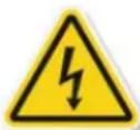
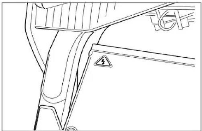
This symbol is located in various locations on the motorcycle to inform you that exposure to high voltage can cause shock, burns and even death.
The high voltage components on the motorcycle should be serviced by technicians with special training.
High voltage cable or wiring has an orange covering. Do not probe, tamper with, cut, or modify high voltage cable or wiring.
Unplug Your Z-Force® Power Pack™
CAUTION: Proper care of the motorcycle's power pack is essential! Once your motorcycle is charged, disconnect the power pack from AC power. Leaving your motorcycle unplugged will maximize long-term power pack health. See page 4.6 for other important information regarding the power pack.
Owner Information
Record information pertaining to your motorcycle here. When contacting your dealer, you may need to provide this information.
Dealer Information Motorcycle Information
Name ____
VIN
Address Model
Power Pack Serial Number ____
Telephone No. ____
Motor Serial Number ____
E-mail ____
Key Code ____
Date of Purchase ____
Identification Numbers
Power Pack Serial Number
The Power Pack serial number is located on the upper front left of the power pack.
Motor Serial Number
The motor serial number is stamped on the motor housing.
Key Code Number
The key code is a 5 digit number used to create duplicate keys. This number is located on a tag that accompanies the original keys.
Vehicle Identification Number (VIN)
The VIN is a 17-digit number stamped on the head tube of the frame. Do not alter or remove this number as it is the legal identifier for your motorcycle.
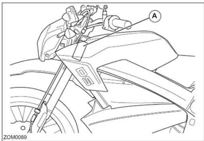
See the location of all important labels on page 2.3.
Chassis Number
The motorcycle chassis number information (A) is affixed to the chassis column.
VIN Break Down
The following breakdown of the VIN will help understand the significance of each digit or character in case you need to reference it when contacting Zero or ordering parts.
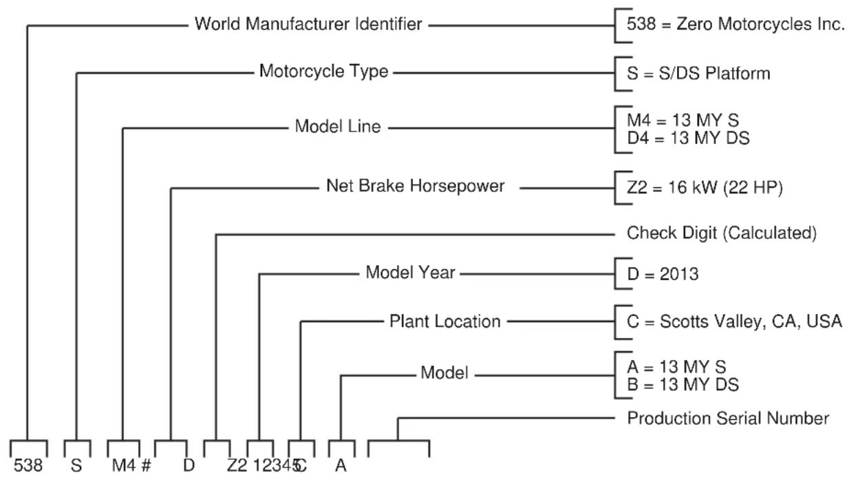
flowchart
graph TD
    A["World Manufacturer Identifier"] --> B["538 = Zero Motorcycles Inc."]
    C["Motorcycle Type"] --> D["S = S/DS Platform"]
    E["Model Line"] --> F["M4 = 13 MY S\nD4 = 13 MY DS"]
    G["Net Brake Horsepower"] --> H["Z2 = 16 kW (22 HP)"]
    I["Check Digit (Calculated)"] --> J["D = 2013"]
    K["Model Year"] --> L["C = Scotts Valley, CA, USA"]
    M["Plant Location"] --> N["A = 13 MY S\nB = 13 MY DS"]
    O["Model"] --> P["Production Serial Number"]
General Information
Technical Specifications
Zero S
The Zero S specifications below apply to both the S ZF8.5 and ZF11.4 models (unless otherwise specified).
| MOTOR | |
| Type Z-ForceTM 75-7 passively air-cooled, high-efficiency, radial flux, permanent magnet, brushless motor. | |
| Controller High efficiency, | 420 amp, 3-phase brushless controller with re-generative deceleration |
| Estimated Top Speed (max) | 95 mph (153 km/h) |
| Estimated Top Speed (sustained) | 80 mph (129 km/h) |
| POWER SYSTEM | |
| Type Z-ForceTM Patented Li-Ion Intelligent Power Pack | |
| Maximum Capacity • ZF8.5: | 8.5 kWh• ZF11.4: 11.4 kWh |
| Nominal Capacity • ZF8.5: | 7.5 kWh• ZF11.4: 10.0 kWh |
| Charge Time (standard) | • ZF8.5: 6.0 hours(100% charged) / 5.5 hours (95% charged)• ZF11.4: 7.9 hours (100% charged) / 7.4 hours (95% charged) |
| Supplemental Charger Quick Charge Time (accessory) | ZF8.5 3.6 hours (100% charged) / 3.1 hours (95% charged)ZF11.4 4.6 hours (100% charged) / 4.1 hours (95% charged) |
| CHAdeMO Recharge Time (0 to 95%) | 1.0 hour |
| CHAdeMO Recharge Time (0 to 100%) | 1.5 hours |
| Input Standard 110 V AC or 220 V AC | |
| Charger Type 1.3kW Integrated | |
| Estimated Power Pack Life to 80% (city) | ZF8.5: 232,000 miles (373,000 km)ZF11.4: 309,000 miles (497,000 km) |
| RANGE | |
| City (EPA UDDS) • ZF8.5 | 103 miles (166 km)ZF11.4 137miles (220 km) |
| Highway, 55 mph (88 km/h) | ZF8.5 64 miles (103 km)ZF11.4 85 miles (137 km) |
| >Combined (City + 55 mph) | ZF8.5 79 miles (127 km)ZF11.4 105 miles (169 km) |
| Highway, 70 mph (112 km/h) | ZF8.5 53 miles (85 km)ZF11.4 70 miles (113 km) |
| >Combined (City + 70 mph) | ZF8.5 70 miles (113 km)ZF11.4 93 miles (150 km) |
General Information
| DRIVETRAIN | |
| Transmission Clutchless Direct Drive | |
| Final Drive 132T/28T,Poly | Chain® GT® CarbonTM belt |
| CHASSIS/SUSPENSION/BRAKES | |
| Front Suspension Travel 5 | 51 in (140 mm) |
| Rear Suspension Travel 5 | 85 in (149 mm) |
| Front Brakes Nissin 2 piston hydraulic313 mm OD rotor, 4.0 mm thick2 piston floating caliper27 mm OD pistons | |
| Rear Brakes Nissin 1 piston hydraulicSingle piston floating caliper, 25.4 mm OD piston | |
| Front Tire 110/70-17 in | |
| Rear Tire 130/70-17 in | |
| Front Wheel 3.00x17 | |
| Rear Wheel 3.50x17 | |
| Front Suspension 38 mm inverted, aluminum slider forks withadjustable compression and rebounddamping | |
| Rear Suspension Piggy-back reservoir shock with adjustablespring preload, compression and rebounddamping | |
| DIMENSION | |
| Wheel Base | 55.4 in (1,406 mm) |
| Seat Height | 31.3 in (794 mm) |
| Rake | 23.8 degrees |
| Trail | 3.2 in (82 mm) |
| WEIGHT | |
| Frame | 19.5 lbs (8.8 kg) |
| Curb Weight | ZF8.5 355 lbs (161 kg)ZF11.4 387 lbs (175 kg) |
| Carrying capacity | ZF8.5 400 lbs (181 kg)ZF11.4 368 lbs (167 kg) |
| ECONOMY | |
| Typical Cost to Recharge | ZF8.5 0.90/€1.28ZF11.41.20/€1.70 |
| Equivalent Fuel Economy, City (EPA UDDS) | ZF8.5 463 MPGe(0.51 L/100 km)ZF11.4 463 MPGe(0.51 L/100 km) |
| Equivalent Fuel Economy (highway 70 mph) | ZF8.5 263 MPGe (1.00 L/100 km)ZF11.4 263 MPGe (1.00 L/100 km) |
General Information
Zero DS
| MOTOR | |
| Type Z-ForceTM 75-7 passively air-cooled, high-efficiency, radial flux, permanent magnet, brushless motor. | |
| Controller High efficiency, 420 amp, 3-phase brushless controller with re-generative deceleration | |
| Estimated Top Speed (max) | 95 mph (153 km/h) |
| Estimated Top Speed (sustained) | 80 mph (129 km/h) |
| POWER SYSTEM | |
| Type Z-ForceTM Patented Li-Ion Intelligent Power Pack | |
| Maximum Capacity • ZF8.5 8.5 kWh• ZF11.4 11.4 kWh | |
| Nominal Capacity • ZF8.5 7.5 kWh• ZF11.4 10.0 kWh | |
| Charge Time (standard) | • ZF8.5 6.0 hours (100% charged)/5.5 hours (95% charged)• ZF11.4 7.9 hours (100% charged)/7.4 hours (95% charged) |
| Supplemental Charger Quick Charge Time (accessory) | • ZF8.5 3.6 hours (100% charged) /3.1 hours (95% charged)• ZF11.4 4.6 hours (100% charged) /4.1 hours (95% charged) |
| CHAdeMO Recharge Time (0 to 95%) | 1.0 hour |
| CHAdeMO Recharge Time (0 to 100%) | 1.5 hours |
| Input Standard 110 V AC or 220 V AC | |
| Charger Type 1.3 kW Integrated | |
| Estimated Power Pack Life to 80% (city) | ZF8.5 213,000 miles (343,000 km)ZF11.4 284,000 miles (457,000 km) |
| RANGE | |
| City (EPA UDDS) • ZF8.5 | 95 miles (153 km)ZF11.4 126 miles (203 km) |
| Highway, 55 mph(88 km/h) | ZF8.5 57 miles (92 km)ZF11.4 76 miles (122 km) |
| >Combined(City + 55 mph) | ZF8.5 71 miles (114 km)ZF11.4 95 miles (153 km) |
| Highway, 70 mph(112 km/h) | ZF8.5 46 miles (74 km)ZF11.4 61 miles (98 km) |
| >Combined (City +70 mph) | ZF8.5 62 miles (100 km)ZF11.4 82 miles (132 km) |
| DRIVETRAIN | |
| Transmission Clutchless Direct Drive | |
| Drive System (standard) 132T / 28T, Poly Chain® GT® CarbonTM belt | |
General Information
| CHASSIS/SUSPENSION/BRAKES | |
| Front Suspension Travel 7 | in (178 mm) |
| Rear Suspension Travel 7 | 69 in (195 mm) |
| Front Brakes Nissin 2 piston | hydraulic313 mm OD rotor, 4.0 mm thick2 piston floating caliper |
| Rear Brakes Nissin 1 piston | hydraulic221 mm OD rotor, 4.5 mm thickSingle piston floating caliper, 25.4 mm OD piston |
| Front Tire 100/90-19 in | |
| Rear Tire 130/80-17 in | |
| Front Wheel 19 x 2.15 in | |
| Rear Wheel 17 x 3.0 in | |
| Front Suspension 38 mm | inverted forks with adjustable compression and rebound damping |
| Rear Suspension Piggy-back | reservoir shock with adjustable spring preload, compression and rebound damping |
| DIMENSION | |
| Wheel Base 56.5 in (1,435 mm) | |
| Seat Height 34.4 in (873 mm) | |
| Rake 26.5 degrees | |
| Trail 4.6 in (117 mm) | |
| WEIGHT | |
| Frame | 19.5 lbs(8.8 kg) |
| Curb Weight | ZF8.5 363 lbs(165 kg)ZF11.4 395 lbs(179 kg) |
| Carrying Capacity | ZF8.5 392 lbs (178 kg)ZF11.4 360 lbs (164 kg) |
| ECONOMY | |
| Typical Cost to Charge | ZF8.5 0.90/€1.28ZF11.41.20/€1.70 |
| Equivalent Fuel Economy, City (EPA UDDS) | ZF8.5 426 MPGe (.55 L/100 km)ZF11.4 426 MPGe (.55 L/100 km) |
| Equivalent Fuel Economy (highway 70 mph) | ZF8.5 205 MPGe (1.15 L/100 km)ZF11.4 205 MPGe (1.15 L/100 km) |
General Information
Vehicle Range
The range of an electric vehicle is defined as the distance the vehicle travels on a single full charge of the power pack. Just like EPA mileage estimates on an automobile, "your mileage may vary." Your range results are a direct reflection of your riding habits. The more conservative you ride the better range you can expect from your Zero S/DS motorcycle.
Some of the factors which affect range include speed, acceleration, number of starts and stops, ambient air temperature, as well as changes in elevation. The combination of these factors, as you travel from one point to another, defines your trip profile. In addition, tire pressure and payload are important considerations.
We suggest that you ride conservatively when you first get your Zero S/DS motorcycle, and get to know your motorcycle and your commute. Once you become familiar with the range versus performance of your motorcycle, then you can adjust your riding characteristics if you so desire. This applies mainly to riders with trip profiles which are at the edge of the performance envelope. Those individuals with relatively short commutes can expect to ride quite aggressively and reach their destination with energy to spare.
Reported motorcycle range values are measured using two different types of industry standard test procedures:
- "City (EPA UDDS)": This test procedure uses a duty cycle known as the "Universal Dynamometer Driving Schedule (UDDS)", which was developed by the U.S. Environmental Protection Agency (EPA) in order to simulate city-type riding.
- "Highway": This test procedure uses two separate constant speeds of 55 mph and 70 mph to simulate highway riding.
Both of these test procedures are run on a single charge, in order to report the associated measured range values.
Range values labeled “Combined” are based on a calculation that assumes a duty cycle comprised of 50% City / 50% Highway.
See technical specification charts on page 1.6 through page 1.8 for these ranges.
Public Charging Stations
There are more public charging stations coming online every day and there may be some in your area. You can charge from a public charging station with either the optional J1772 S/DS Zero motorcycle accessory or CHAdeMO Zero motorcycle accessory. These stations are often available at a variety of locations including shopping centers, city parking lots, airports, hotels, government offices, and other businesses. We recommend that you search the internet for locations in your area. For example, search for “charging stations.”
CHAdeMO Charger
Your Zero motorcycle can utilize a quick charging CHAdeMO charger system. A CHAdeMO charger can charge your motorcycle in about one hour. For additional information contact your Zero Motorcycles dealer.
Maximizing Your Range
Range varies in electric motorcycles similarly to how it varies in gas motorcycles. However, the big difference between electric and gas is that energy consumption is averaged over a shorter distance on an electric motorcycle. Electric motorcycles are designed for convenient daily recharges versus less frequent and less convenient trips to the gas station. As a result, the same electric motorcycle often yields different ranges from one full recharge to the next.
How to Predict the Range
To generally predict how an electric motorcycle's range will be affected, you can use the four factors:
- route
- rider
- weather
- motorcycle
By considering each of these factors, you can use specifications such as 'city range' as standards to estimate what the motorcycle's real world range will be under the your particular usage case.
General Information
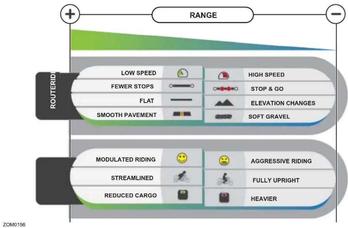
bar
| Router ride | Range | | --- | --- | | LOW SPEED | HIGH SPEED | | FEWER STOPS | STOP & GO | | FLAT | ELEVATION CHANGES | | SMOOTH PAVEMENT | SOFT GRAVEL | | MODULATED RIDING | AGGRESSIVE RIDING | | STREAMLINED | FULLY UPRIGHT | | REDUCED CARGO | HEAVIER | ZOM0156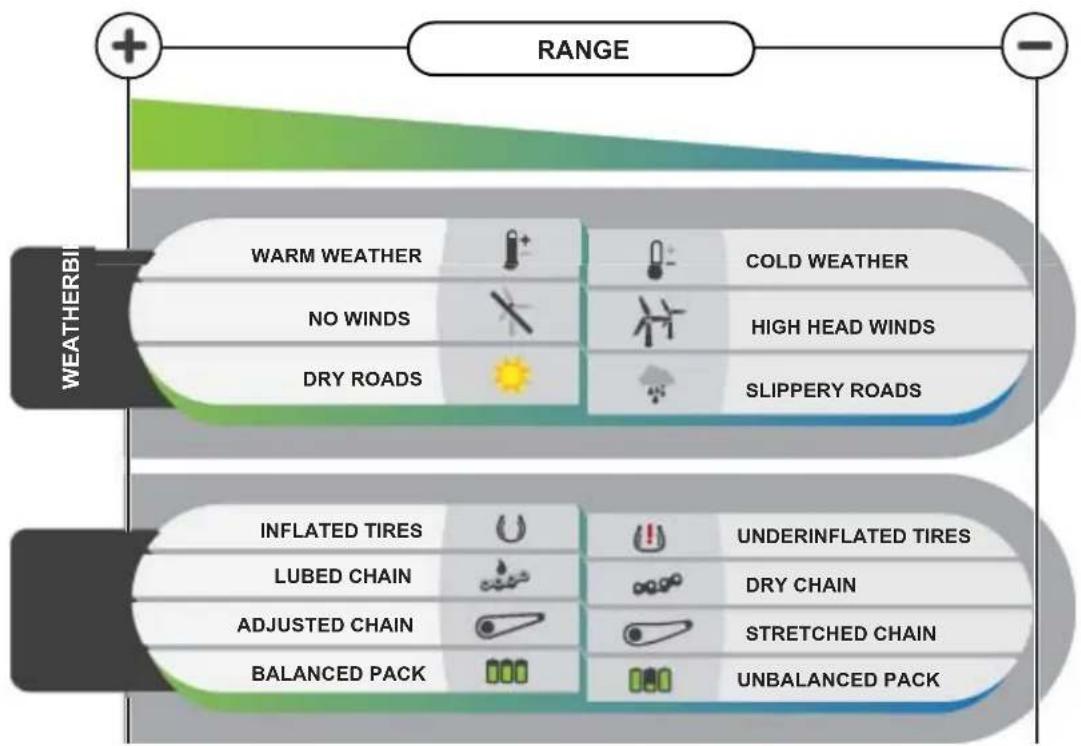
ZOM0157
General Information
Emissions Information
The Zero S/DS electric motorcycle is a true freeway capable zero emissions vehicle under California Air Resources Board (CARB), U.S. Federal (EPA), and European Union standards. It uses no gasoline or other liquid fuel. It has no tailpipe and therefore no tailpipe emissions. It also has no exhaust or evaporative emissions. Because the Zero S/DS runs solely on electricity, it is the only kind of vehicle which actually gets cleaner in terms of air pollution each year, as the electricity grid gets cleaner and more renewable. Zero Emissions Vehicles (ZEV's) offer greater efficiency, and can help solve the serious air pollution, global warming, and energy security problems facing the country and the world.
WARNING! Please use only Zero approved parts and accessories for your Zero motorcycle. Parts and accessories for your Zero motorcycle have been checked and tested for safety and suitability. Zero is unable to accept any liability whatsoever for parts and accessories which have not been approved
General Information
Transporting
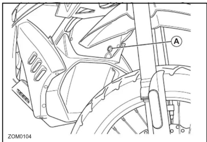
When the front fork is compressed, the built up pressure must be released to help prevent fork seal leaks. There is a 3 mm Allen "bleed" screw located just in front of the rebound adjuster on each fork leg. This "bleed" screw (A) is used to release the built up pressure. Loosen the screw slowly, but do not remove. Once all the air is out, tighten the bleed screw.
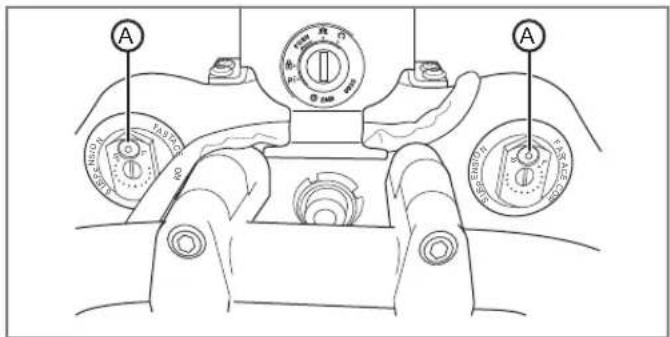
The fork must be fully extended (most likely on a stand or balanced on the kickstand with the front tire in the air) then the air can be bled and capped. Ensure that the screw is tightened before riding.
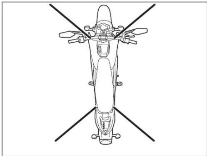
It is recommended that the motorcycle be tied-down using ratchet straps. Place the ratchet straps around a frame contact point. Soft straps must be used to prevent scratches or other damage.
Use two ratchet straps in the front and two in the rear. The tie down straps should be at a 45^ angle from the motorcycle. Follow the manufacturer's instructions for the ratchet straps you are using.
natural_image
Top-down line drawing of a motorcycle with four cross-sectional views (no text or symbols)Notes
General Safety Precautions
General Safety Precautions
- This is a performance motorcycle and should be treated with extreme caution.
- Proper safety gear, including a regionally approved helmet, riding boots, gloves, and protective clothing should be worn while riding to reduce the risk of potential injury. We highly recommend the use of full height riding boots since the vast majority of motorcycle injuries are leg and foot injuries. It is not recommended to ride without the correct protective clothing; this applies to even short journeys, and to every season of the year.
- Read all additional warnings and product instructions in this owner's manual, as well as safety labels, before operating your electric motorcycle.
- Never permit a guest to ride your electric motorcycle without proper instruction.
- Never use alcohol or mind-altering drugs before operating your electric motorcycle.
-
Persons unwilling or unable to take responsibility for their actions should not use this motorcycle. You assume all responsibility while operating your motorcycle. The seller assumes no liability for misuse or operator negligence.
-
Prior to each use the rider must check everything in the "every ride" column of the maintenance schedule on page 5.2, and the charge level of the power pack as indicated on the instrument panel charge indicator.
- Your safety depends in part on the good mechanical condition of the motorcycle. Be sure to follow the maintenance schedule and adjustment requirements contained in this manual. Be sure you understand the importance of checking all items thoroughly before riding.
- Modifications to the motorcycle may render the vehicle unsafe and may cause severe personal injury. Zero Motorcycles cannot be held liable for non-approved modifications.
- Be very careful when loading or adding accessories to your motorcycle. Large, bulky, or heavy items may adversely affect the handling and performance of your motorcycle.
General Safety Precautions
Important Operating Information
Several operating considerations are listed below:
- Always turn the key switch and motor stop switch to the OFF position when not actively riding. It is very easy to forget that the motorcycle is powered up because it is silent. An accident can occur if the motorcycle is left powered up while getting on or off the motorcycle.
- Turn the motor stop switch OFF when backing up or pushing the motorcycle while dismounted.
- Use the rear brake when you are stopped on an incline. Do not hold the motorcycle using partial throttle or damage to the motor may occur.
- Plug your motorcycle into an AC power source to recharge it after each use. Once recharged, disconnect from the AC power source. Leaving your motorcycle unplugged between charges will maximize the long-term health of the power pack. You should also use the supplied cable as it is designed for use with your motorcycle's electrical components.
- While unplugged with the key in the OFF position, the motorcycle's electronics will consume a very small amount of power and the power pack will drain extremely slowly. If you don't ride for an extended period of time (30 days or more), you may want to plug the motorcycle into an AC power source to charge it for a few hours prior to your next ride.
CAUTION: Only charge the Zero power pack with the motorcycle's on-board charger or the approved Zero accessory charger.
- The power pack does not require, or tolerate, deep discharging. To get the most power pack life, recharge each power pack immediately after each ride. Leaving a power pack in a discharged state will cause damage.
- Failure to follow power pack storage and charging instructions as described in this Zero Motorcycles Owner's Manual may void the warranty of your Zero motorcycle. These guidelines have been rigorously tested to ensure maximum power pack efficiency and service.
Location of Important Labels
The vehicle could contain the following information for both North American and European models:
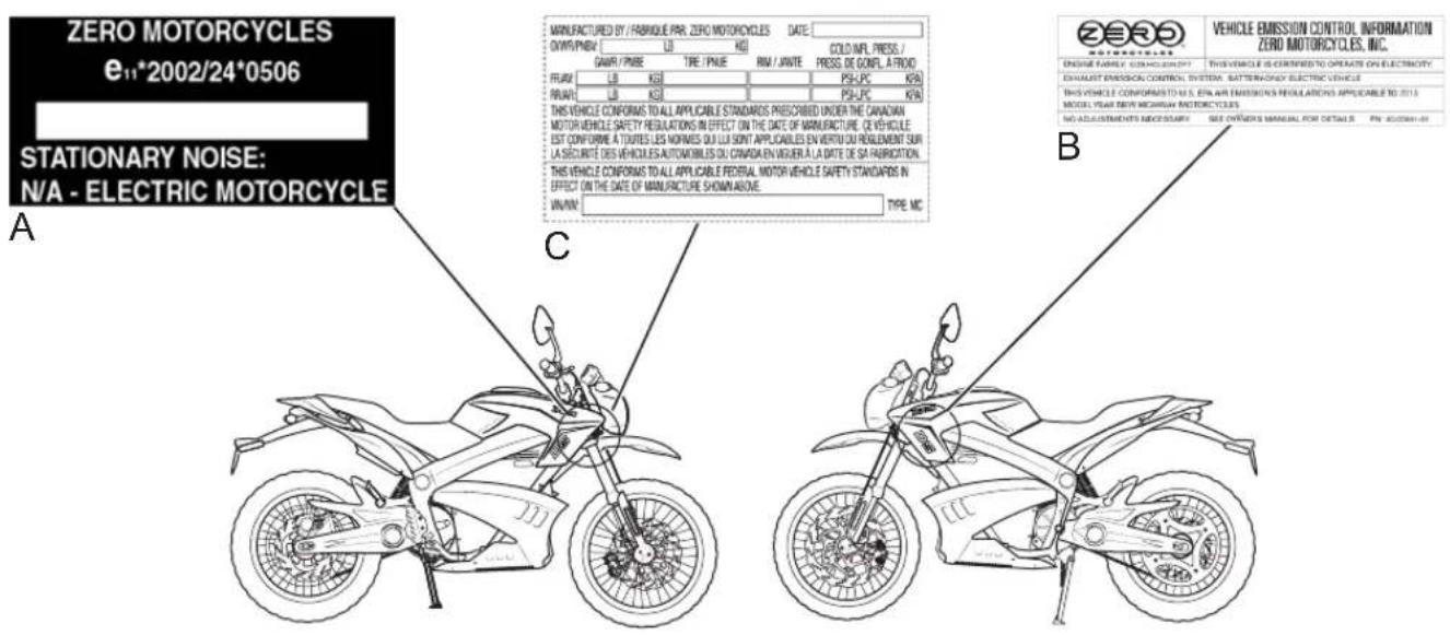
ZOM0105
A. VIN label (European Union) - certification label
B. VECI (Vehicle Emission Control Information) label
C. VIN label (North America) - certification label shown
Location of Important Labels
Anti-Tamper Control Label (Europe only)
The anti-tamper control label (shown below) is located on the left-side of the frame.
Location of Important Labels
High Voltage Warning Label
natural_image
Technical line drawing of a mechanical component with no visible text or symbolsAffixed to battery
Notes
Controls and Components
THIS PAGE INTENTIONALLY LEFT BLANK
Controls and Components
Motorcycle Controls
ZOM0102
Controls and Components
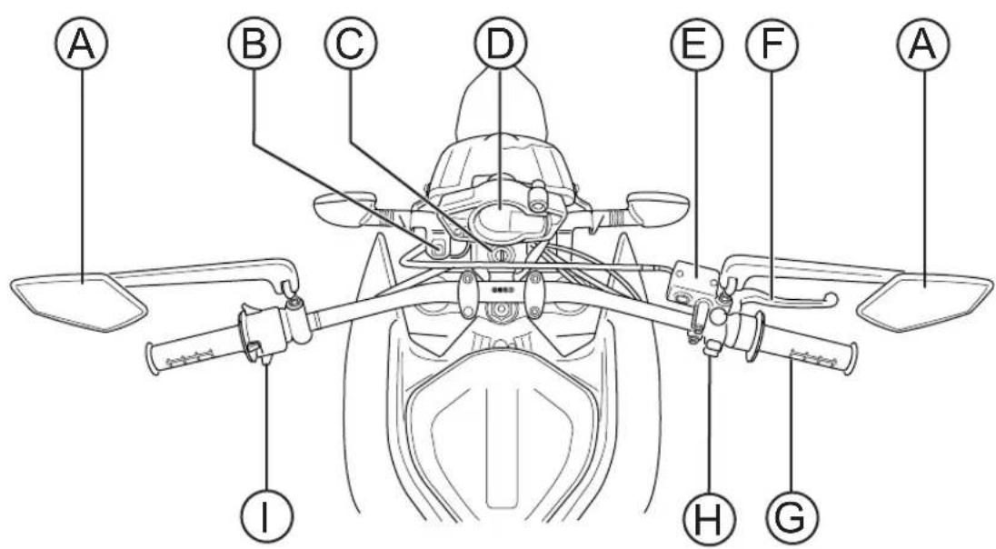
A.Mirrors
This motorcycle is equipped with convex mirrors. A convex mirror has a curved surface. Convex mirrors offer a greater field of view than a similar flat mirror. However, the greater field of view makes objects seem further away than they really are. Care must be used when judging the distance of objects seen in these mirrors.
B. Performance Level Switch
For description and operation see "Performance Level Switch", on page 3-11.
C.Key Switch/Steering Lock
For description and operation see "Key Switch/Steering Lock Positions", on page 4-4
D. Instrument Panel. For description and operation see "Instrument Panel", on page 3-8.
E.Front Brake Fluid Reservoir
For description and operation see "Brakes", on page 5-10.
FFront Brake Lever
For description and operation see "Handlebar Controls", on page 3-12.
G.Throttle Control
For description and operation see "Handlebar Controls", on page 3-12.
H.Motor Stop Switch
For description and operation see "Handlebar Controls", on page 3-12.
I. Left Handlebar Control
For description and operation see "Handlebar Controls", on page 3-12.
Controls and Components
Left Side View
Controls and Components
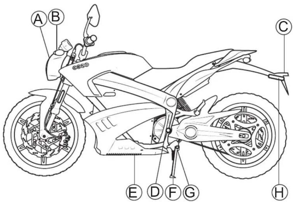
A.Headlight
- For headlight operation, see "Handlebar Controls", on page 3-12.
- For headlight bulb replacement, see "Headlight Bulb Replacement", on page 5-21.
- For headlight alignment, see "Headlight Alignment", on page 5-20.
B. Turn Signals
- For turn signal operation, see "Handlebar Controls", on page 3-12.
- For turn signal light bulb replacement, see "Turn Signal Light Bulb Replacement", on page 5-23.
C.Brake/Tail Light
For brake/tail light bulb replacement, see "Brake/Tail LED Replacement", on page 5-23.
D.AC Charger Power Connection
For description and operation, see page 4.6.
E.Integrated Power Pack Charger
For description and operation, see page 4.6.
FKickstand
The kickstand swings out from the side and supports the motorcycle when parked. The key switch should be in the OFF position when parked.
G.Kickstand Switch
This switch is a safety feature that prevents motor operation when the kickstand is down. If the kickstand were down when riding it could contact the ground causing you to lose control of the motorcycle and cause personal injury.
WARNING! Park only on a flat firm surface otherwise the motorcycle could fall over causing damage.
H.Rear Turn Signal
For turn signal operation, see "Handlebar Controls", on page 3-12.
Controls and Components
Right Side View
ZOM0155
Controls and Components
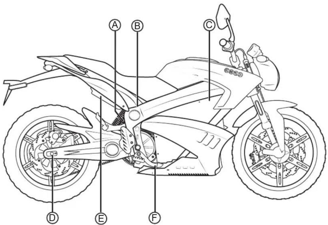
A. Rear Break Fluid Reservoir
See "Rear Brake", on page 5-12
B.Auxiliary Power Pack Charging Connection For
description and operation see "Quick Charging (Off
Board Accessory Charger)”, on page 4-11. The
auxiliary connector is located above the motor.
C.Power Pack
For description and operation see "Power Pack", on page 4-6.
D.Drive Chain/Belt Tension Adjuster
See "Drive Chain (Optional)", on page 5-17 or
"Checking Drive Belt Tension", on page 5-15 for
additional information.
E.Brushless Motor Controller
Precisely “meters” the flow of electricity from the power pack to the motor according to the action of the throttle and surrounding conditions.
FRear Brake Pedal
The rear brake pedal controls the rear brake when the pedal is pressed. When braking, the throttle should be in the closed position. The brake light illuminates when the rear brake pedal is applied.
Controls and Components
Instrument Panel
ZOM0152
Controls and Components
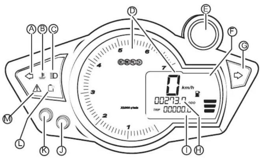
A.Left Indicator Turn Signal
An arrow on the instrument panel flashes green in the same direction as selected by the turn signal switch. This arrow
remains on until the turn signal request has been canceled.
B. Temperature Lamp
This flashes in the event that you exceed the motorcycle's performance capabilities. The temperature warning lamp indicates
the temperature of the motor, controller temperature, or the battery over/under temperature. See page 4.14 for more information
C. High Beam Indicator
When the headlight high beam is on, this indicator illuminates blue, and remains on until the high beam is turned off.
D.Tachometer/Speedometer
The speedometer is a digital display in either kilometers per hour (km/h) or miles per hour (mph). The analog display portion provides the tachometer (large dial) information.
E.Main Power Indicator
Indicates the motorcycle is live or ready to move if the throttle is actuated. For troubleshooting, see "Troubleshooting Your Motorcycle", on page 6-1.
FCharge Indicator
This indicator displays the amount of energy remaining in the power pack, similar to the fuel gauge on a gasoline powered vehicle.
G.Right Turn Signal Indicator
An arrow on the instrument panel flashes green in the same direction as selected by the turn signal switch. This remains on
until the turn signal request has been canceled
H.Odometer
The odometer displays the total distance the motorcycle has been ridden in kilometers or miles.
I. Trip Odometer
The trip odometer displays individual trip mileage, and is reset by pressing and holding the adjust button.
J.Adjust Button
By pressing the adjust button you can toggle between the trip odometer settings. Holding it down will clear the trip odometer resetting it back to zero.
Controls and Components
K.Select Button
By pressing the select button you can change the display units that appear on the instrument panel between English or Metric.
L.Charging Indicator
Flashes slowly when the motorcycle is accepting a charge. The indicator flashes rapidly when a charging error is detected.
The indicator is solid green when the battery is completely charged
M.System Warning Indicator
If a fault has been detected, count the number of times the red LED flashes. See the table on page 6.2
Controls and Components
Performance Level Switch
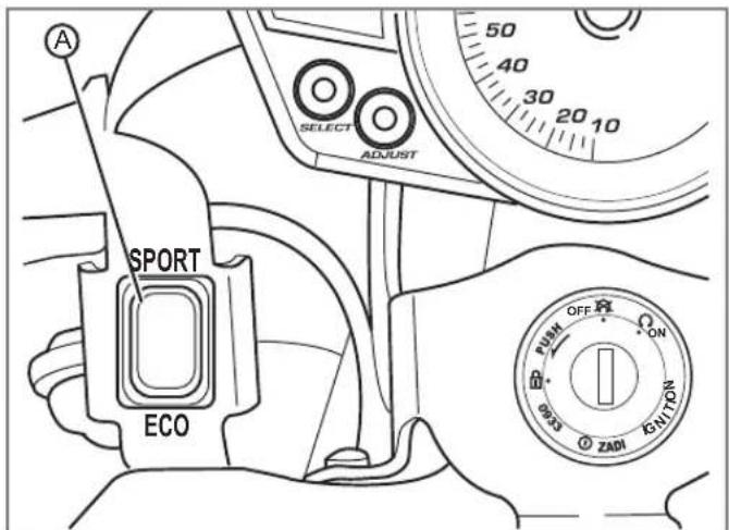
The performance level switch (A) is a two position switch that toggles between ECO and SPORT modes. You can switch between performance modes while riding but the change will not be executed until the throttle is returned to the closed position.
The ECO position reduces the acceleration and top speed of the motorcycle. It is an ideal position to use for times when you want softer acceleration. This position is also good for newer riders and for extending range.
The SPORT position causes the motorcycle to accelerate at a significantly faster rate. This position is recommended for advanced riders.
Those who take advantage of the ECO position are likely to see a slight increase in range and experience greater regenerative braking. You can also customize the performance settings using the smart phone application (refer to "Smartphone Application", on page 3-15).
Controls and Components
Handlebar Controls
Controls and Components
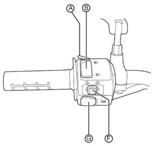
A. Flash-to-Pass
When the headlight is in the low beam position, push the flash-to-pass switch and the high beam illuminates and stays illuminated until the switch is released. When released, this switch defaults back to the low beam position. The high beam indicator also illuminates.
B.Headlight High/Low Beam Switch
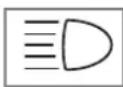
When the switch is pushed, the headlight changes from low beam to high beam. It stays in the selected position until it is
switched back. When in high beam position, the high beam indicator on the instrument panel illuminates.
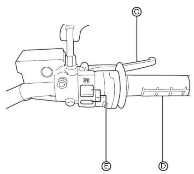
C.Front Brake Lever
The front brake lever controls the front brake when the lever is squeezed. When braking, the throttle should be in the closed position. The brake light also illuminates.
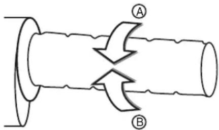
D.Throttle Control
Twist the throttle in a counter-clockwise rotation (A) to energize the motor and start the motorcycle in a forward direction. Release the throttle and it snaps back to the closed position (B), de-energizing the motor, and regenerative braking begins.
When the motorcycle is moving and the throttle control is in the fully closed position, the regenerative
braking feature activates. Regenerative braking takes some of the energy from the moving motorcycle and turns it back into electrical energy. This energy is then stored back into the power pack, contributing to increased energy efficiency. A slight drag is felt when the regenerative braking is activated. If you want to coast without the regenerative braking, hold the throttle just off of the fully closed position.
Controls and Components
E.Motor Stop Switch
When the switch (A) is pressed, it cuts off power to the motor controller. The motor controller remains in this state until the ON (B) button is pressed. The switch does not turn off all electrical circuits, just the operation of the motor.
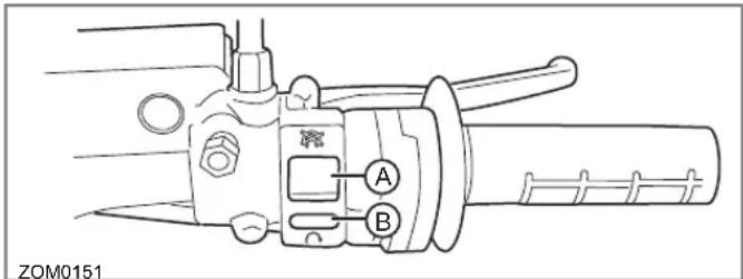
F.Turn Signal Switch
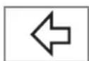
When the turn signal switch is pushed in the left or right position, the corresponding front and rear turn signals flash. When the
turn signal switch is ON, the corresponding turn signal indicator on the instrument panel illuminates.
Always signal your turns and other maneuvers as required by law. Unlike an automobile, the turn signals must always be canceled manually on the motorcycle. Push in on the switch and it returns to the center, or, OFF position.
G.Horn Button
When the key is in the ON position, the horn sounds when the button is pressed. Electric vehicles run quietly; the horn can be used to warn pedestrians or other motorists of your presence.
Controls and Components
Tank Bag
Your Zero motorcycle makes use of a tank bag for additional storage. You can remove the tank bag by pulling upwards on its sides.
Note: Before riding your Zero motorcycle secure the tank back with the lock (above the tank bag). At high speeds the bag could eject, if is not secured.

natural_image
Technical line drawing of a mechanical assembly with no visible text or symbolsSmartphone Application
You can download a smartphone application that lets you perform the following tasks related to your motorcycle:
- Adjust the ECO mode for performance gains
• Collect and email logs to Zero support staff - Examine the precise State of Charge (SOC) of your motorcycle
- Examine real time power usage
The Smartphone application is available for free at both the Apple iTunes store and Google Play store. iTunes® is a registered trademark of Apple. Google Play® store is a registered trademark Google.
Notes
First Time Set-Up
If your motorcycle was direct-shipped you will need to perform the following:
- Remove the motorcycle from its shipping crate. See Unpacking Your Zero motorcycle on page 4.2.
- Your Zero Motorcycle is shipped fully charged from the factory. If necessary, see "Power Pack", on page 4.6.
- Identify and inspect wheels for spoke tension and/or damage (DS only).
- Check the tire pressure and adjust to proper specifications. See "Tire Inflation", on page 5.14.
- Inspect the hydraulic brake system. Follow the hydraulic line from the reservoirs to the calipers and verify that there are no leaks or damage to the brake lines. Verify that the brakes function properly.
- Make sure the motorcycle key switch is OFF, then twist the throttle to make sure its rotation is smooth, and it returns correctly.
- Inspect bolts and make sure they are tight. See page 5.10 general maintenance information. Double check the fork, wheel, and brake bolts.
- Insert the key in the key switch and turn the key to the ON position. The gauge performs a self test sweep. The charge indicator should read fully charged.
Starting and Operating
Unpacking Your Zero Motorcycle
Although unpacking your Zero motorcycle can be done by a single person, it is recommended to have a second person to help lift and remove your motorcycle from the crate base.
Outer Box Cover
- Cut and remove the two outer box retention straps.
- Unscrew stabilizer bar bolts, one on each side of outer box.
- Open box top and remove inner cardboard end reinforcement sleeves.
- Unscrew stabilizer bar from handlebar end and remove.
- Unscrew lower crate cover retaining screws and washers.
- Lift or cut outer box away from motorcycle.
Inner Assembly
- Carefully remove plastic cover from motorcycle.
- Locate small parts box below motorcycle and put to the side. (This box contains important documentation, owner's manual, keys, etc.).
- Remove the tie down straps from crate base.
-
Carefully lift rear portion of the motorcycle over the swingarm standoff and off crate base.
-
Carefully lift front wheel out of crate base.
- Deploy kickstand, lean motorcycle and inspect in accordance with delivery inspection sheet.
Recycling
Your Zero Motorcycles shipping crate and packaging materials were designed to be completely recycled. Please cut down and recycle all cardboard, plastic, and metal materials in appropriate receptacles.
The tie down straps that accompanied your motorcycle can be reused as regular tie down straps.
General Operation
General Operation
This section describes several items you should examine before operation.
Pre-Ride Inspection
Before operating the Zero S/DS motorcycle, check the following to make sure the motorcycle is secure and intact:
- Power Pack. Make sure the instrument panel charge indicator is indicating a charged power pack. If the charge indicator reads below 6 bars (½ charge), we suggest you recharge before use. Always keep the charger cord with the motorcycle.
- Drive Belt. Check the belt tension and condition. Adjust if necessary. See "Drive Belt", on page 5.15.
- Brakes. Squeeze the brake lever and press the brake pedal individually while pushing the motorcycle to see if it rolls. You should be able to lock-up the wheels completely by applying the brakes.
- Throttle. With the key switch in the OFF position, apply the throttle and release to verify that the throttle is smooth and returns correctly.
- Tires. Check both tires for condition and tread depth. Check cold tire pressure frequently. Check for damage and alignment. Maintain correct tire pressure as specified on page 5.14. Replace the tires when the tread height is 0.08 in (2 mm) or less.
CAUTION: Under-inflation is the most common cause of tire failure and may result in severe tire cracking, tread separation, "blowout," or unexpected loss of motorcycle control causing personal injury and possible death.
- Electrical System. Check for correct function of the headlight, turn signals, and the brake/tail lights.
General Operation
Key Switch/Steering Lock Positions
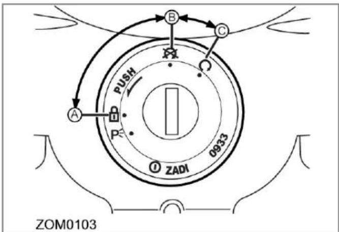
This is a three-position switch that is located on the fork in front of the handlebar. The switch positions are as follows:
- Steering Lock (A)
- OFF (B)
• ON (C)
The key should be removed from the motorcycle when parked to prevent theft. The key can be removed in either the OFF or steering lock position.
Steering Lock
Using the steering lock when parked prevents unauthorized use and helps prevent theft.
To operate the steering lock
- Turn the handlebar all the way to the left.
- Push the key down from the OFF position and turn the key counter-clockwise while still pushing it in.
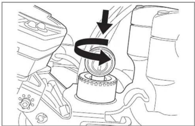
natural_image
Mechanical component diagram showing a rotating shaft and housing with directional arrows indicating motion (no text or symbols)- Remove the key.
To unlock the steering lock
- Install the key and turn clockwise.
- Remove the key.
OFF Position
This position is used to turn the motorcycle OFF, disabling the electrical system.
ON Position
This position is used for operating the motorcycle. In this position the following sequence occurs:
- Lights turn ON
- Instrument Panel display turns ON
General Operation
Power Pack
The battery is located within the power pack and requires no special break in period.
The 2013 Zero S and DS leverage a completely new battery cell chemistry and configuration. Not only does the ZF11.4 power pack enable you to go beyond 137 miles (220 km), it is also designed to last the life of the motorcycle. The integrated onboard charger minimizes charge time and can work in parallel with Zero's quick charge accessories to cut charge times by as much as 70%.
The charging time will remain the same if the onboard charger is connected to a 120 V AC or a 240 V AC supply. The normal recharging time of the power pack to a 100% charge is usually less than 6 hours for the ZF8.5 and 7.9 hours for ZF11.4 in mild ambient temperatures. Out of the normal temperature range, charging and run-time times will vary. The power pack should not be used outside of the range of 23°F to 140°F (-5°C to 60°C); the Battery Management System (BMS) turns off the power controller outside of this range.
Note: The Battery will not charge if below 0^ C or 32^ F.
Plug your motorcycle into an AC power source to recharge it after each use. Once recharged, disconnect from the AC power source. Leaving your motorcycle unplugged
between charges will maximize the long-term health of the power pack.
While unplugged with the key in the OFF position, the motorcycle's electronics will consume a very small amount of power and the power pack will drain extremely slowly. If you don't ride for an extended period of time (30 days or more), you may want to plug the motorcycle into an AC power source to charge it for a few hours prior to your next ride.
The power pack must be charged within 24 hours if fully discharged. If stored long-term, check the state of charge at least monthly and charge it back up to 60% if it has dropped below 30%. See “Parking and Long Term Storage”, on page 6.27 for more information.
Battery Management System (BMS)
Every power pack contains a Battery Management System (BMS) which monitors the condition of the cells, and optimizes the charging process to provide the highest-performance, longest-range, and longest life for the power pack.
The BMS safeguards the power pack by means of safety interlocks. These interlocks turn off or control certain operations that could damage the power pack. See "Safety Interlocks", on page 6.10 for more information.
The BMS also monitors the power pack for a host of predefined conditions, and then takes actions according to those conditions. See, "Battery Management System", on page 6.2 and "Cold and Hot Weather Considerations", on page 6.8 for further information.
The BMS is sealed inside the power pack. As a rider, you don't need to think much about the BMS - it just silently does its job as you charge, ride, and store your motorcycle.
Add On Electrical Equipment
WARNING! Do not add anything electrical to your motorcycle unless approved by your dealer. Some electrical components can damage your motorcycle. Some add-on electrical equipment can keep other components from working as they should or can dramatically reduce the range and/or life expectancy of the power pack.
Power Pack Charger
Connect your power pack to the charger after each use. Once recharged, disconnect from the AC power source. Leaving your motorcycle unplugged between charges will maximize the long-term health of the power pack. You should use the supplied cable as it is designed for use with your motorcycle's electrical components. The power pack must be charged within 24 hours if fully discharged. If you don't ride for an extended period of time (30 days or more), you may want to plug the motorcycle into an AC power source to charge it for a few hours prior to your next ride.
WARNING! Only charge the Zero power pack with the Zero charger. The charger is located under the power pack.
When charging the motorcycle's power pack, the charger can be left ON, even after the power pack is fully charged. But unplugging your motorcycle after it is fully charged will
General Operation
maximize long-term power pack health. If left connected, there are two possible cases that can occur:
- When connected to the charger, the power pack will receive a full charge. Once fully charged, the charger will check the status of the power pack once every 72 hours to ensure that it maintains a full charge. When fully charged, a green light illuminates on the charger. Should the charger not read that the power pack is full, it continues to attempt to fully charge the power pack. In this event the green light may not illuminate; however, the power pack may be fully charged. To ensure that the power pack is charged, check the charge indicator on the instrument panel prior to riding.
- If the power pack terminates the charge before the charger reaches the state previously mentioned, then the charger continues to cycle and tops off the power pack until the power pack is removed from the charger, or the charger reaches the complete state previously noted.
The onboard charger LED indicator (A) is visible through the front of the battery housing. A circular lens displays the colored LED's status of the charge.
When charging the motorcycle, the LEDs flash from left to right, then the LEDs display how much of the battery (on a score of 1 to 4) is charged. Next the LEDs cycle from left to right once more. For example, if 3 of the 4 LEDs are illuminated, the battery is 3/4 charged. Refer to "Battery Management System", on page 6.2 for more information.
General Operation
Charging the Power Pack
WARNING! Charge the Zero power pack with the Zero charger.
It is possible for lithium ion cells to overheat and fail.
Note: It is recommended to charge in a location that is away from combustible materials and in a well ventilated area. If charging your Zero motorcycle outdoors, avoid charging in the rain.
The maximum power pack internal charging temperature is 131^ F ( 55^ C). If the power pack's internal temperature is over 131^ F ( 55^ C), it will not accept a charge until it is moved to a cooler location. Also, if the power pack has just been run hard, it may internally be above 131^ F ( 55^ C) even if the ambient temperature is lower.
If you experience a power pack that will not take a charge, you should ensure the internal temperature is below 131°F (55°C). If the power pack was recently run and it will not take a charge, the power pack should cool and begin taking a charge in around 30 minutes or less.
The maximum charging temperature cutoff is a power pack longevity feature. Charging at higher temperatures can shorten the life of the power pack.
Note: Frequent top off charging is good for the power pack's life span, so do not hesitate to charge frequently.
To charge using the standard charger:
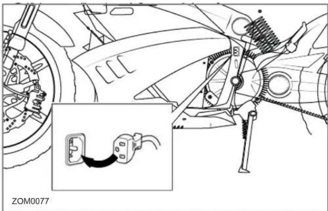
- Plug the supplied power cord (A) into the onboard charger connector. Always keep the power cord with the motorcycle.
natural_image
Technical line drawing of a car's front wheel assembly with an inset showing a cable connector (no text or symbols)- Always connect the charger to a GROUNDED outlet. When using an extension cord, avoid excessive voltage drops by using a grounded, 3-wire, 12-AWG cord no longer than 7.6 m (25 ft). The charger can be used on 120 V AC or 240 V AC current. The voltage does not change the amount of time that the motorcycle takes to charge.
General Operation
Note: AVOID connecting the Zero charger and another device to a single 120 V AC 15A/20A circuit, as it may become overloaded. Zero chargers draw as much as 10 amps from the 120 V AC circuit when charging.
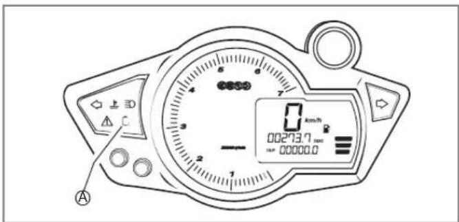
- The charging icon (A) flashes as the battery is being charged. Once charging is complete, the icon stays illuminated
-
Charging a fully discharged power pack to 100% takes about:
-
ZF8.5 6 hours
• ZF11.4 7.9 hours
Note: The charging icon is solid green when fully charged and plugged into the charger.
Quick Charging (Off Board Accessory Charger)
The “scalable” quick charging feature allows up to three supplemental accessory chargers (in addition to the existing integrated charger) to be connected to the motorcycle. Use of supplemental accessory chargers can reduce the charging time by up to 70%.
Note: The time for charging the motorcycle using quick charging will vary with the number of chargers used.
The accessory charging connector is located above the motor. For more information on how to connect additional chargers, refer to the quick charger's owner's manual.
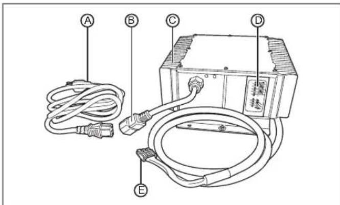
A.AC Power Cord
B.AC Power Cord Connection
C.Power Pack Charger
D.Charger LED Indicators
E. Connector (to motorcycle)
General Operation
To charge using the Quick Charger
- Ensure that the key switch is in the OFF position.
- Locate the accessory charging connector (above the motor) and remove the protective cover.
- Connect the power pack charger to the power pack connector.
natural_image
Technical line drawing of a mechanical assembly with spring and housing (no text or symbols)- Always connect the charger to a GROUNDED outlet. When using an extension cord, avoid excessive voltage drops by using a grounded, 3-wire, 12-AWG cord no longer than 7.6 m (25 ft). The charger can be used on
120 V AC or 240 V AC current. The voltage does not change the amount of time that the motorcycle takes to charge.
-
Connect the off board accessory charger. See "Quick Charging (Off Board Accessory Charger)", on page 4.11.
-
When the power pack is fully charged, disconnect the charger(s) and reinstall the protective cover.
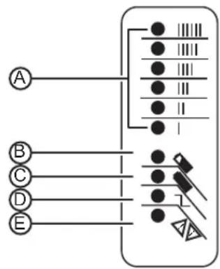
Quick Charger LED Indicators
flowchart
graph TD
    A["A"] --> M1["● III III"]
    A --> M2["● III III"]
    A --> M3["● III"]
    A --> M4["● II"]
    A --> M5["● II"]
    B["B"] --> M1
    C["C"] --> M2
    D["D"] --> M3
    E["E"] --> M4
    M1 --> M5
    M2 --> M6["● 7"]
    M3 --> M7["● 7"]
    M4 --> M8["● 7"]
    M5 --> M9["● 7"]
    M6 --> M10["● 7"]
    M7 --> M11["● 7"]
    M8 --> M12["● 7"]
    M9 --> M13["● 7"]
A.Ammeter
The Ammeter LED is an amber indicator that indicates the amount of current output and should gradually ramp down from "II/III" to "I".
B.80% Charge
The 80% Charge LED is an amber indicator. If it is on solid, the bulk charge phase is complete, 80% charged. Charger is now in absorption phase. If the
indicator is flashing, there are two issues that can cause this to occur:
C.100% Charge
The 100% Charge LED is a green indicator. If it is on solid, the charging is complete and the charger will enter maintenance mode. If it is flashing, the absorption phase is complete and the charger is in finish phase.
D.AC ON
The AC ON LED is an amber indicator. It is on solid, the AC power is good. If it is flashing, the AC voltage is low. Check for proper voltage, and if an extension cord is being used, verify that it is of the correct length. Maximum length is 25 ft. (7.6 m) 12 AWG.
E.Fault
The Fault LED is a red indicator which indicates there is a charger error. If it is flashing, reset the charger and see "Troubleshooting", on page 6.1.
CHAdeMO Charger
Your Zero motorcycle can utilize an optional quick charging CHAdeMO charger system. A CHAdeMO charger can charge your motorcycle in about one hour. For additional information contact your Zero Motorcycles dealer.
General Operation
Operating Your Motorcycle
This section describes how to safely operate your motorcycle.
Starting
- Turn the key switch to the ON position.
- Verify that the charge indicator reads fully charged.
- Press the motor stop switch to the ON position.
- With the kickstand up, twist the throttle toward you (counter-clockwise) to increase speed. When the throttle is twisted away from you (clockwise), the speed decreases.
Braking
On the right handlebar is the hand operated brake lever. The brake lever controls the front brake when the lever is squeezed. On the right lower side, next to the foot peg, is the foot operated brake pedal. This pedal controls the rear brake. When braking, the throttle should be in the closed position.
CAUTION: If you apply the front or rear brake hard enough, it is possible to lock the wheels. This could cause you to lose control of the motorcycle. We suggest progressive use of the brakes to bring the Zero motorcycle to a complete stop without locking the wheels. Your Zero motorcycle is a light weight performance product and therefore practice is recommended to safely perfect emergency stops.
Stopping Your Motorcycle
To stop your motorcycle:
- With the throttle in the closed position press the motor stop switch to the OFF position. This switch can also be used in an emergency to shut the motor off.
- Turn the key switch to the OFF position and remove the key. To prevent theft, the key should be removed anytime the motorcycle is left unattended.
- Be sure to charge the power pack after each ride.
Temperature Indicator
Zero Motorcycles has developed the most advanced passively air-cooled electric powertrain for your Zero motorcycle, delivering an unsurpassed level of simplicity, power/energy density, low weight and ease of maintenance. However, this passively air-cooled powertrain cannot be operated indefinitely at high power / high rpm without reaching its thermal limitations. Hence, your Zero motorcycle has a sophisticated thermal management strategy to ensure the long term performance and durability of its powertrain.
General Operation
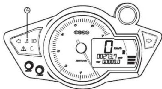
The red temperature indicator light (A) on your Zero motorcycle's instrument cluster has two informational stages.
- Stage 1, is presented by flashing this indicator and advises you that the bike is about to enter its thermal strategy. To avoid encountering an enforced power reduction, you can choose to slow down a bit until the indicator stops flashing.
- Stage 2, if temperature continues to build, the indicator light will go solid, letting you know that the thermal strategy is now being applied and that your motorcycle's power will be reduced accordingly. If you encounter the strategy while trying to maintain a high
vehicle speed, the effect of the strategy will be that your motorcycle will be gradually slowed down to the point that the top speed of the bike is "sustainable", from a thermal standpoint. If you encounter the strategy due to a different sustained high power event, such as continued powering through a low traction surface, power will simply be reduced to ensure the continued safe operation of your powertrain.
Please note that the lighting of this temperature indicator does not indicate that there's anything malfunctioning with your Zero motorcycle; it is simply letting you know that the thermal strategy is working. If you do not moderate your speed/power, the bike's system will reduce your speed/power until your Zero can maintain its maximum allowable thermal state; but no harm whatsoever will result from this, since this is exactly how the strategy is meant to function.
General Operation
Front Suspension Adjustment
A shock has two main actions: compression when the shock gets loaded, and rebound when the shock returns back to full length. Compression damping is the adjustment that determines how fast or slow the fork compresses. Rebound damping is the adjustment that determines how fast or slow the fork rebounds.
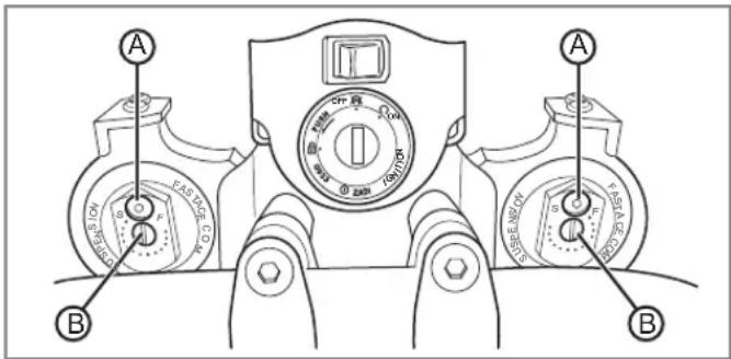
Bleed Screw
The 3 mm Allen M5 screw (A) at the top of the fork leg is the "bleed" screw. The bleed screw serves two purposes:
- Transporting your motorcycle. See "Transporting", on page 1.15.
- Bleeding the fork: Bleed the fork regularly, let any excess air out after each ride.
Rebound Damping
The rebound damping is adjusted by turning the slotted brass adjuster screw (B) on the top of both fork legs. Next to the screw are the letters "S-F," meaning Slow and Fast. The adjuster has 18 stages of adjustment. This determines how quickly the fork returns to its extended position after being compressed.
- Turning the rebound adjuster screw clockwise slows the rebound speed down making it better for larger, rolling terrain or bumps.
- Turning the rebound adjuster screw counter-clockwise increases the rebound speed making it better for smaller, rougher bumps. Adjust each fork leg evenly.
General Operation
Compression Damping
The compression damping is adjusted by turning a screw on the bottom of each fork leg. There is a rubber dust cover protecting the jam nut (A) securing the screw (B). The adjuster has 12 stages of adjustment.
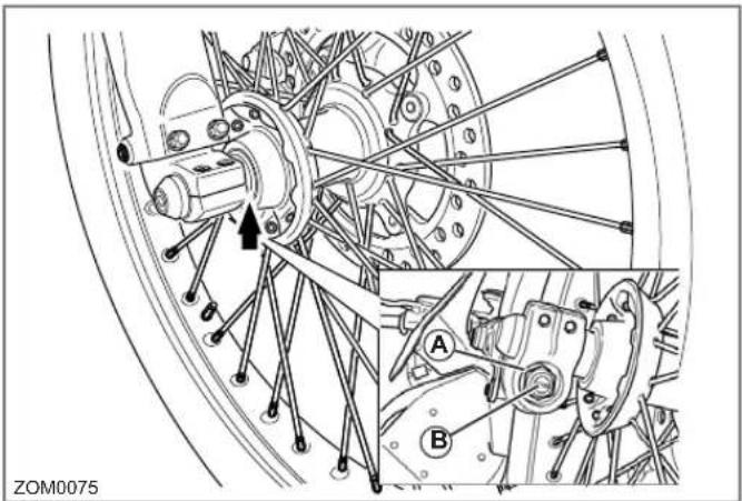
- Turn the adjuster clockwise for slower compression.
- To speed up compression, turn the adjuster counter-clockwise.
Start with a middle setting and fine tune the compression from there. Proper compression allows the tire to track the ground over consecutive bumps. Compression that is set
too slow will pack-up (feel harsh over consecutive bumps) while compression that is set too fast will cause the fork to bottom out harshly. If the fork is bottoming out, turn the adjuster one click at a time until the bottom-out stops. Adjust each fork leg evenly. Replace the rubber dust cover after the adjustment.
Note: Adjusters should never be forced completely "Fast" or "Slow"; always leave one click of adjustment in either direction.
Factory Supplied Front Suspension Settings
The following information will allow you to adjust the front suspension back to the factory settings the motorcycle was originally supplied with.
S Models
| ADJUSTMENT SETTING | |
| Front Fork Compression 8 clicks out from fully closed | |
| Front Fork Rebound 10 clicks out from fully closed | |
DS Models
| ADJUSTMENT SETTING | |
| Front Fork Compression 3 clicks out from fully closed | |
| Front Fork Rebound 8 clicks out from fully closed | |
General Operation
Rear Shock Adjustment
Spring Adjustment
Obtaining the correct rear spring preload is critical for proper handling. The spring preload must be set to match the weight of the rider. The spring is preloaded for an 180 lb (82 kg) rider. This puts the rear tire 1/3 of the way through its vertical travel. Heavier riders require stiffer spring rates. A good approximation of your rear spring requirements can be found by measuring the rear suspension's sag. This measurement quickly determines if your rear spring is approximately correct for your weight. This adjustment is a recommended guideline; personal riding preference may vary from the specifications given.
To Check the Sag value:
- Support your motorcycle on a stand with the rear wheel off the ground.
- Measure vertically from the rear axle to the rear fender. Mark this spot as it is used for other measurements.
- Record this measurement (this is the measurement referred to as M1).
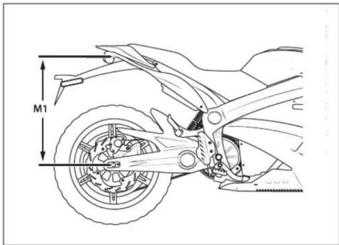
- Remove the motorcycle from the stand.
- Wearing your normal riding apparel, sit on the motorcycle.
- Have an assistant hold the motorcycle up, your feet should be on both pegs.
- Bounce the suspension a couple of times.
- Have a second assistant take a measurement using the same locations as in step 2.
- Record this measurement (this is the measurement referred to as M2).
General Operation
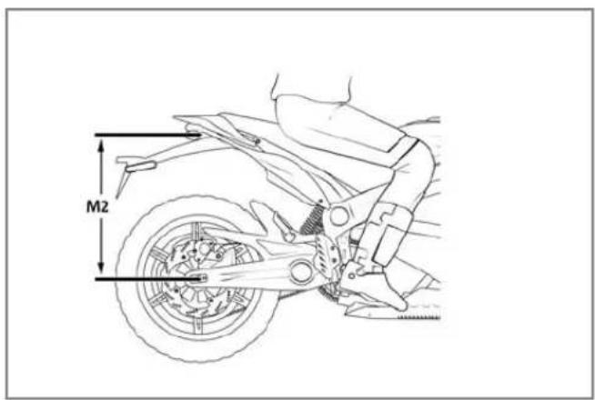
- Subtract the second measurement (M2) from the first measurement (M1).
Example:
| Measurement Operator Value | |
| M1 23.62 in (600 mm) | |
| M2 - 21.65 in (550 mm) | |
| Sag = 1.97 in (50 mm) |
The total sag is 1.97 in (50 mm). Refer to the chart below for the correct sag. If the sag is not correct, the spring pre-load should be adjusted.
| MODEL SAG | |
| S 1.97 in (50 mm) | |
| DS 2.56 in (65 mm) |
General Operation
Spring Pre-load Adjustment
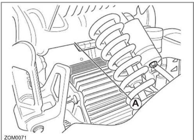
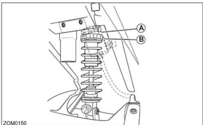
- Clean any dirt or debris from the threads of the shock near the lock ring (A).
- Using a lock ring wrench loosen the lock nut (A).
- For measurements less than the specified value, decrease the pre-load on the spring by turning the spring nut (B) counter-clockwise on the shock. If more than the specified value, increase the pre-load on the spring by turning the spring nut (B) clockwise on the shock.
Rebound Adjustment
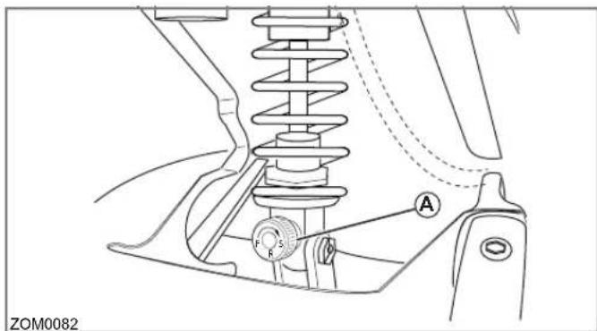
The rebound adjuster knob (A) is at the bottom of the shock. It has 8 stages of adjustment. Printed on the knob is S-F, meaning Slow and Fast. The rebound adjuster knob controls how slow or fast the shock returns to its extended position after being compressed. Turning the knob clockwise, or S direction, is good for big impacts.
Turning the knob counter-clockwise, or F direction, is good for smaller and more frequent impacts.
Compression Adjustment
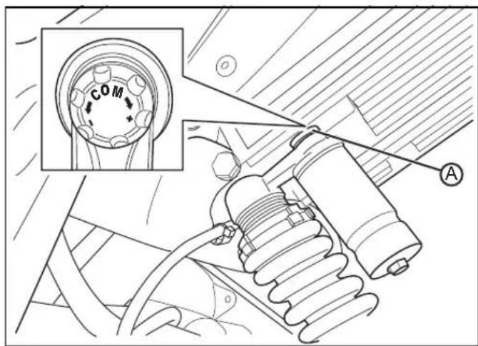
The compression adjustment knob is at the top of the shock. It has 18 stages of adjustment. The knob has “+” (slower compression) and “-” (faster compression). Turn the adjuster clockwise for slower compression. To speed up compression, turn the adjuster counter-clockwise. Start with a middle setting and fine tune the compression from there. Proper compression allows the tire to track the ground over consecutive bumps. Compression that is set too slow will pack-up (feel harsh over consecutive bumps) while compression that is set too fast causes the shock to bottom out harshly. If the shock is bottoming out, turn the adjuster one click at a time until the bottom out stops.
Note: Adjusters should never be forced completely "Fast" or "Slow"; always leave one click of adjustment in either direction.
General Operation
Factory Supplied Rear Suspension Settings
The following information will allow you to adjust the rear suspension back to the factory settings the motorcycle was originally supplied with.
S Models
| ADJUSTMENT SETTING | |
| Rear Shock Compression 10 clicks out from fully closed | |
| Rear Shock Rebound 4 clicks out from fully closed | |
| Rear Shock Spring Preload 135mm | |
DS Models
| ADJUSTMENT SETTING | |
| Rear Shock Compression 5 clicks out from fully closed | |
| Rear Shock Rebound 3 clicks out from fully closed | |
| Rear Shock Spring Preload 170mm | |
Owner's Responsibilities
Listed below are the responsibilities afforded to the owner:
- This owner's manual should be considered a permanent part of this motorcycle and should remain with it even if the motorcycle is subsequently sold.
- Perform routine care and maintenance of your electric motorcycle as detailed in this owner's manual.
- Use only Zero approved parts and Zero Motorcycles accessories.
- The operator is responsible for learning and obeying all country, federal, state, and local laws governing the operations of an electric motorcycle.
- Always wear a regionally approved helmet, goggles, appropriate boots, and all other appropriate safety equipment when operating an electric motorcycle.
Parts/Maintenance Items
The proper replacement parts, fluids, and lubricants to use are listed in the table below.
| PART NUMBER | |
| Headlight Bulb H4 (55/60 watt) | |
| Turn Signal Light Bulb (amber) RY10W (10 watt) | |
| Brake/Tail Light Bulb LED (replace the entire unit) | |
| Front Running light Bulb W3W (3 watt) | |
| Brake Fluid DOT 4 | |
Maintaining Your Motorcycle
Maintenance Schedule
The scheduled maintenance must be performed in accordance with this chart to keep the Zero S/DS motorcycle in top running condition. The initial maintenance is vitally important and must not be neglected. Where time and mileage are listed, follow the interval that occurs first.
| # ITEM ROUTINE EVERY | RIDE | INITIAL INITIAL ODOMETER MILEAGE READING | |||||||
| 600 mi(1K km)or1 month | 4K mi(7K km)or6 months | 8K mi(13K km)or12 months | 12K mi(19K km)or18 months | 16K mi(25K km)or24 months | 20K mi(31K km)or30 months | ||||
| 1 Front Brake Check operation, and for fluidleakage. Replace brake pads ifnecessary. | √√√√√√ | ||||||||
| 2 Rear Brake Check operation, and for fluidleakage. Replace brake pads ifnecessary. | √√√√√√ | ||||||||
| 3 Wheels Check run-out, and for damage.Replace if necessary. | √√√√√ | ||||||||
| 4 Tires - Check tread depth, and fordamage. Replace if necessary.- Check air pressure. See page5-9. Correct if necessary. | √√√√√ | ||||||||
| 5 WheelBearings | Check bearings for smoothoperation. Replace if necessary. | √√√√√√ | |||||||
Maintaining Your Motorcycle
| # | ITEM ROUTINE EVERY | RIDE | INITIAL INITIAL | ODOMETER MILEAGE READING | ||||
| 600 mi(1K km)or1 month | 4K mi(7K km)or6 months | 8K mi(13K km)or12 months | 12K mi(19K km)or18 months | 16K mi(25K km)or24 months | 20K mi(31K km)or30 months | |||
| 6 | Drive Chain - Check chain slack /alignment and condition.- Adjust and lubricate chain with chain lubricant thoroughly.- Replace worn chain. | √ Every | 600 mi (1,000 km) and after washing the motorcycle or riding in the rain. | |||||
| 7 | Drive Belt | - Check belt slack and condition.- Replace a worn/damaged belt.- Check for cracking and/or replace the belt every 40K km (25K mi) | √ | |||||
| 8 | Steering Bearings | - Check all chassis fittings and fasteners.- Correct if necessary. | √√√√Repack √ | |||||
| 9 | Chassis Fasteners | - Check all chassis | √√√√√ | |||||
| 10 | Front Brake Lever Pivot Shaft | - Apply silicon grease lightly.- Check operation and for oil leakage.- Service/rebuild if necessary. | √√√√√√ | |||||
| 11 | Front Fork - Check operation and for oil leakage.- Service/rebuild if necessary. | √√√√√√ | ||||||
| 12 | Rear Shock Absorber Assembly | - Check operation and for oil leakage. Replace if necessary | √√√√√√ | |||||
Maintaining Your Motorcycle
| # ITEM ROUTINE EVERY | RIDE | INITIAL INITIAL ODOMETER MILEAGE READING | |||||||
| 600 mi(1K km)or1 month | 4K mi(7K km)or6 months | 8K mi(13K km)or12 months | 12K mi(19K km)or18 months | 16K mi(25K km)or24 months | 20K mi(31K km)or30 months | ||||
| 13 Throttle Grip - Check operation and free play. | |||||||||
| 13 KickstandPivots | - Check operation.- Apply silicon grease lightly. | ||||||||
| 15 KickstandSwitch | Check operation and replace if necessary. | ||||||||
Note: From 24,000 mi (37,000 km) or 36 months, repeat the maintenance intervals starting from 8,000 mi (13,000) or 12 months.
Component Fasteners
Periodically check and tighten the following fasteners on your motorcycle.
Torque Table
| LOCATION ITEM TORQUE NOTES | |||
| A | Front axle end bolts | 19 lb ft (26 Nm) | Use LOCTITE® 242® (or equivalent) |
| B | Headlight bolts | 12 lb ft (16 Nm) | Use LOCTITE® 242® (or equivalent) |
| C | Front caliper mount bolts | 20 Nm(20 Nm) | Use LOCTITE® 242® (or equivalent) |
| D Shock mount bolts 38 lb ft (52 Nm) - | |||
| E | Rear brake pedal pivot bolt | 34 lb ft (46 Nm) | Use LOCTITE® 242® (or equivalent) |
| F | Rear axle nut | 75 lb ft (20 Nm) | Use LOCTITE® 242® (or equivalent) |
| G | Rear axle pinch bolts | 19 lb ft (26 Nm) | Use LOCTITE® 242® (or equivalent) |
| H | Controller heat sink to frame bolts (rear) | 19 lb ft (26 Nm) | - |
| I | Motor mount bolts (rear) | 18 lb ft (24 Nm) | - |
| J | Controller heat sink to frame (front) | 19 lb ft (26 Nm) | - |
| K | Main pivot bolt/nut (swingarm) | 75 lb ft (102 Nm) | - |
| L | Motor mount bolts (front) | 22 lb ft (30 Nm) | - |
| M | Upper/Lower triple clamps pinch bolts | 17 lb ft (23 Nm) - upper15 lb ft (20 Nm) - lower | Use LOCTITE® 242® (or equivalent) |
| N | Front axle pinch bolts | 9 lb ft (12 Nm) | Use LOCTITE® 242® (or equivalent) |
| O | Rear sprocket to cast wheel, 4 bolts (S model) | 25 lb ft (34 Nm) | Use LOCTITE® 242® (or equivalent) |
| P | Rear brake master cylinder to frame bolts | 17 lb ft (23 Nm) | Use LOCTITE® 242® (or equivalent) |
| Q | Rear brake pedal pivot bolt | 34 lb ft (46 Nm) | Use LOCTITE® 242® (or equivalent) |
| R | Handlebar clamp mount bolts | 19 lb ft (26 Nm) | - |
| S | Seat retaining bolts | 15 lb ft (20 Nm) | - |
Maintaining Your Motorcycle
Left Side of Motorcycle
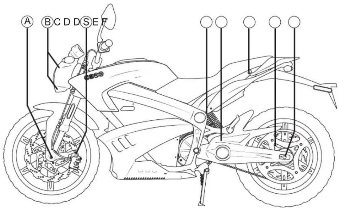
ZOM0154
Refer to Torque table on page 5.5.
Right Side of Motorcycle
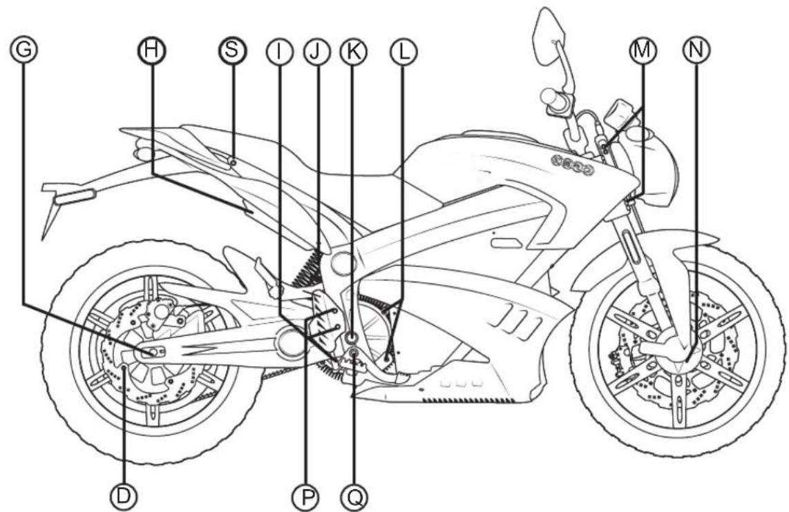
ZOM0153
Refer to Torque table on page 5.5.
Maintaining Your Motorcycle
Handlebars
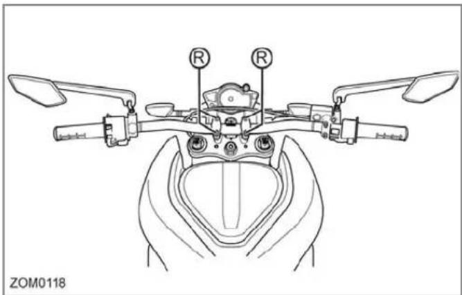
Refer to Torque table, page 5.5.
Power Pack
WARNING! You must leave your motorcycle on the charger if you expect it to sit in storage or unused for over 90 days.
The power pack must be charged within 24 hours if fully discharged, and charged within 90 days if stored fully charged.
Zero recommends you plug in your Zero motorcycle after 7 days, even if fully charged. Please leave your Zero motorcycle plugged in whenever possible.
- The power pack is a lithium ion power system. While it does require charging, it does not require maintenance.
- The power pack should be kept away from excessive heat. The lithium ion cells should not get above 160^ F ( 71^ C). Do not store in a hot trailer or leave the power pack in direct sunlight.
- Only an authorized service agent is qualified to have access to the power pack.
- Dispose of the power pack according to your state and local laws. It is encouraged that the power pack be recycled rather than disposed of in landfills.
- Please contact Zero at support@zeromotorcycles.com or locate a recycling center in your area.
General Maintenance
Brakes
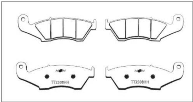
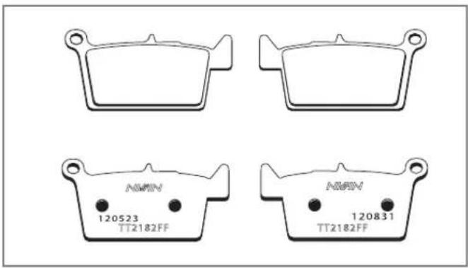
This section describes how to inspect the brake fluid level for both the front and rear brakes. Your motorcycle uses Nissin brake pads for stopping power. Both front and rear pad examples are shown below.
Front Brake Pads
An example of the front brake pads is shown below.
Rear Brake Pads
An example of the front brake pads is shown below.
Brake Fluid Level Inspection
WARNING! Do not spill brake fluid on painted surfaces; the finish could be damaged. Spilling brake fluid on the ABS body plastics will cause them to crack. Clean off any brake fluid spills immediately.
Always place a shop towel under the master cylinder reservoir prior to removing cover/cap.
Low fluid levels may indicate worn brake pads or a leak in the hydraulic system. Inspect the brake pads for wear and/or the hydraulic system for leaks. Use only new DOT 4 brake fluid from a sealed container.
Front Brake
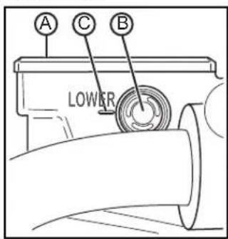
Inspect the level of the front brake fluid through the sight glass (B). If the fluid level is visibly below the low level indicator (C), brake fluid must be added. Clean any dirt or debris from the cover (A) before opening the reservoir.
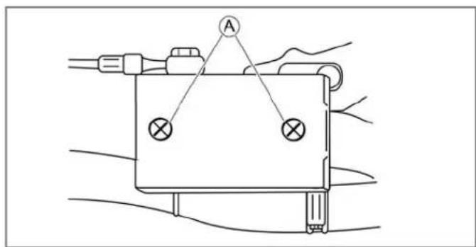
- Remove the two screws (A) securing the cover onto the reservoir.
- Add new DOT 4 brake fluid.
- Inspect the cover seal, ensuring that it is free of any wear or damage and that it is positioned correctly.
- Install the cover and tighten the screws.
General Maintenance
Rear Brake
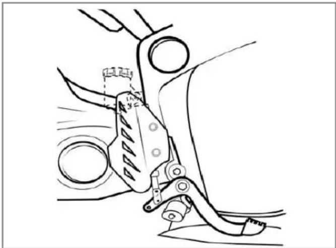
The reservoir housing is located inboard on the frame behind the heel guard.
natural_image
Technical line drawing of a mechanical device with no visible text or symbolsInspect the level of the rear brake fluid through the reservoir housing. If the fluid level is visibly below the low minimum "LOWER" indicator (B), brake fluid must be added. Clean any dirt or debris from the cap and reservoir opening (A) before opening the reservoir.
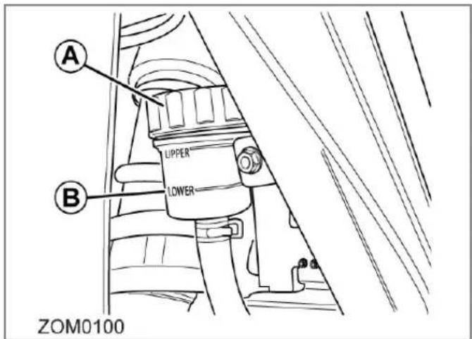
Unscrew the cap and add new DOT 4 brake fluid. Inspect the cap seal ensuring that it is free of any wear or damage then reinstall the cap.
Brake Pad Inspection
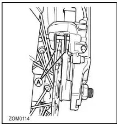
The brake pads must be inspected when specified in the maintenance schedule. See the Maintenance Schedule on page 5.2 for additional information. Visually inspect the brakes by looking at the remaining brake pad material through the sides of the brake caliper. Replace the brake pads if either pad's thickness is 0.053 in (1.35 mm) or less. If the brake pads (A) are worn, replace both brake pads immediately.
natural_image
Technical line drawing of a mechanical assembly with labeled component A (no readable text or symbols)The brake rotor should also be checked for thickness. The minimum thickness is 0.15 in (3.85 mm).
Suspension
Front
- For maintenance, see Maintenance Schedule on page 5.2.
- To adjust the fork, see Suspension Adjustment on page 4.16.
Rear
CAUTION: The shock absorber assembly contains highly pressurized gas.
- Do not attempt to tamper with or open the cylinder or shock.
- Do not subject the shock to high temperature or open flame.
WARNING! Doing either of the above actions can cause the cylinder or shock to explode causing personal injury or death.
For maintenance, see Maintenance Schedule on page 5.2.
To adjust the fork, see Suspension Adjustment on page 4.16.
General Maintenance
Wheels And Tires
Inspect both wheels for the following:
- Bent, loose, or missing spokes (DS only)
- Bent or cracked rims
- Impact marks on the rims
Inspect both tires for the following:
- Cuts, cracks, splits, or missing tread lugs in the tread or sidewall area
- Bumps or bulges within the tire body
- Uneven tire tread wear. Wear on one side of the tire tread or flat spots in the tire tread indicate a problem with the tire or motorcycle.
- Exposed tire thread or cords
If either of the wheels or tires are found to have any of the above conditions, replace the wheel and tire immediately.
Tire Inflation
CAUTION: Under-inflation is the most common cause of tire failure and may result in severe tire cracking, tread separation, "blowout," or unexpected loss of motorcycle control causing personal injury and possible death.
Tire pressure should be checked and adjusted before each ride. Tire pressure is checked using an accurate gauge when the tires are cold. This means that the tires have not been ridden on for 3 hours. Always replace the valve stem cap when finished.
| MODEL FRONT REAR | |
| S 206 kPa (30 PSI) 206 kPa (30 PSI) | |
| DS 199 kPa (29 PSI) 186 kPa (27 PSI) |
Drive Belt
The drive belt provides low maintenance and quiet operation with minimal stretch. Keep dirt, grease, oil, and debris off the belt and sprockets. The drive belt tension should be checked and adjusted at the intervals specified in the Maintenance Schedule. For maintenance information, see the Maintenance Schedule on page 5.2.
Clean the belt with mild soap and water when washing your motorcycle. Towel dry and inspect for the following:
- Cuts or unusual wear patterns.
- Damage to the center of the belt.
- Outside edge beveling. Some beveling is common but it indicates that sprockets are misaligned.
- Outside ribbed surface for signs of stone puncture.
- Inside (tooth portion) of belt for exposed tensile cords normally covered by nylon layer and polyethylene layer. This condition will result in belt failure and indicates worn sprocket teeth.
- Signs of puncture or cracking at the base of the belt teeth.
If any of the above conditions are found, the belt should be replaced.
Checking Drive Belt Tension
Proper belt tension is essential for optimum operation of the drive system.
Lack of belt tension can lead to “ratcheting”. The teeth of the belt slide over the teeth of the rear sprocket. This causes an unpleasant sound; the ratcheting can also cause damage to the carbon tensile cords. If ratcheting has occurred you should replace the belt before the next time you ride.
Too much tension can increase the wear of your drive system and the system can drag.
The tension is checked by using a Tension Tester.
The Tension Tester has a plastic measurement arm, located in a slot. Along this slot there is a measuring scale. The point of intersection of the measurement arm and the measuring scale shows the tension of the belt. There is a button (clicking pad) on the upper side of the Tension Tester, where you can secure your finger with a rubber band holder. A spring is located underneath this clicking pad. If a certain pressure is applied to the spring, it makes a clicking sound.
General Maintenance
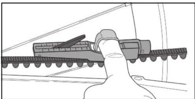
natural_image
Illustration of a hand gripping a train with a ramp, no text or symbols present- Remove the key from the key switch.
- Press the Tension Tester steadily to the middle of the upper side of the belt. The "lip" will lead the tester on to the belt.
- Slowly increase the pressure on the tester, until you hear a clicking sound. Do not increase the pressure after the tester has clicked.
- Remove the tester carefully from the belt. Avoid rough movements of the tester, as this would change the results of the measurement. The measurement should be in the range of 20-30 kg.
Drive Belt Adjustment Procedure
- Remove key from the key switch.
- Loosen the rear axle nut (C).
- Loosen left and right (A) jam nuts (13mm) in order to make adjustments.
- Turn adjustment bolt (B) to adjust belt tension.
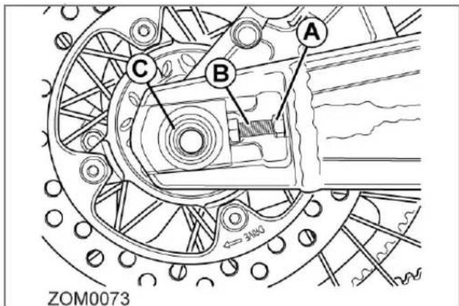
- Tighten left and right jam nuts (A) to secure the belt.
- Tighten the rear axle nut (C).
- Test ride the motorcycle.
- Recheck the belt for proper adjustment after the test ride and readjust, if necessary.
General Maintenance
Drive Chain (Optional)
Cleaning The Drive Chain
CAUTION: Wear safety glasses when cleaning the chain to prevent eye injuries.
CAUTION: Never place your hand or any other body part between the chain and sprockets. Work with the chain only in the middle between the two sprockets. Failure to do so could result in serious personal injury.
CAUTION: Do not allow any of the cleaner to get on the brake rotors or brake pads. If the brake rotors or brake pads are contaminated with cleaner, it will impair the motorcycle's ability to stop. This could result in serious personal injury.
CAUTION: Never have the motor spinning the wheel. Turn the wheel only by hand. Failure to do so could result in serious personal injury.
Follow the manufacturer's instructions for the chain cleaner you are using; below are the general guidelines.
- Remove the key from the key switch.
-
Set the motorcycle on a stand or lift so the rear wheel is free to spin. While turning the wheel by HAND, spray the inside of your entire chain with a good coating of chain cleaner and let it sit for a few minutes.
-
Using a brush, fill the bristles with spray from the chain cleaner. Begin gently scrubbing the chain on the top of your swingarm using the brush.
- Do this for the entire length of the chain. Now do the same thing for the inside/bottom of the chain.
- Using the brush, clean both sides of the rear sprocket. Let this soak for 5 minutes.
- Using a water hose, rinse the entire chain. Then, using a clean rag, wipe any residual moisture from the chain.
General Maintenance
Lubricating The Drive Chain
CAUTION: Wear safety glasses when lubricating the chain to prevent eye injuries.
CAUTION: Never have the motor spinning the wheel. Turn the wheel only by hand. Failure to do so could result in serious personal injury.
CAUTION: Never place your hand between the chain and sprockets. Work with the chain only in the middle between the two sprockets. Failure to do so could result in serious personal injury.
CAUTION: Do not allow any of the lubricant to get on the brake rotors or brake pads. If the brake rotors or brake pads are contaminated with lubricant, it will impair the motorcycle's ability to stop. This could result in serious personal injury.
Follow the manufacturer's instructions for the chain lubricant you are using; below are the general guidelines. Do not allow any of the lubricant to get on the brake rotor.
To lubricate the chain:
- Turn the wheel backwards slowly and spray the inside of the chain on the inside of the links.
- Turn the wheel backwards slowly and spray the outside of the chain on the outside of the links.
- Let the motorcycle stand for 30 minutes to allow the lubricant to penetrate the link rollers.
Checking the Drive Chain
- Remove the key from the key switch.
- Using a ruler, grasp the chain halfway between the front and rear sprockets.
- The chain should move 63 in (16 mm) in either direction, so 1.25 in (32 mm) of total free play.
- If the chain's free play is not within specifications, it will need to be adjusted.

General Maintenance
Adjusting the Drive Chain
- Remove the key from the key switch.
- Loosen the 13 mm jam nut (A) on the chain tensioner.
- Turn the adjuster bolt (B) a 1/4 turn at a time until the chain adjustment is within specification.
- Tighten the 13 mm jam nut on the chain tensioner.
- Test ride the motorcycle.
- Recheck the chain for proper adjustment after the test ride and readjust if necessary.
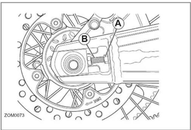
General Maintenance
Headlight Alignment
The headlight should be checked for correct alignment periodically. It must be aligned any time the suspension sag is adjusted because this affects the headlight alignment. Before the headlight can be aligned, the suspension sag and tire pressure must be correctly adjusted. The headlight can be adjusted vertically. If the vertical adjustment is off, it causes the beam to point too close to or too far ahead of the motorcycle. With the headlight on the low beam position, the motorcycle perpendicular to the ground, and the operator sitting on the motorcycle, verify the beam alignment. The motorcycle is shipped with the headlight at a 0.5-2.5% dip.
The adjustment screw (A) is located on the back upper right corner of the headlamp. To adjust the headlight, turn the screw until the correct beam alignment is achieved.
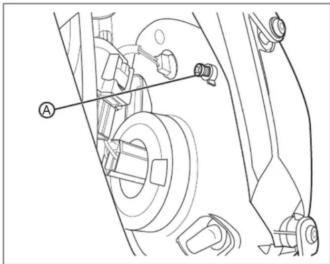
Headlight Bulb Replacement
CAUTION: Halogen bulbs contain gas under pressure. Handling a bulb improperly could cause it to shatter into flying glass fragments. To help avoid personal injury:
- Turn the key switch OFF and allow the bulb to cool before changing the bulb.
- Leave the key switch OFF until the bulb change is complete.
- Always wear eye protection when changing a halogen bulb.
- Avoid touching the glass.
To replace the bulb:
- Working from behind the headlight, disconnect the headlight bulb connector (A) and rubber cover (B).
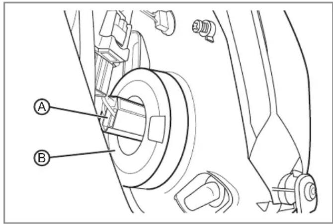
General Maintenance
- Remove the headlight bulb retainer (A) by turning it counter-clockwise.
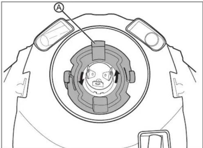
natural_image
Technical diagram of a mechanical component with circular housing and directional arrows indicating motion (no text or symbols)- Remove the headlight bulb by pulling it straight out.
WARNING! Do not touch the glass portion of the headlight bulb. Keep the headlight bulb free of contaminants. Oil from your fingers or contaminants will shorten the life of the bulb. Thoroughly clean any fingerprints or contaminants from the bulb using a clean cloth moistened with alcohol.
-
Install the headlight bulb into the lens.
-
Install the headlight bulb retainer and turn it clockwise until it locks into position.
-
Install the headlight bulb rubber cover.
-
Connect the headlight bulb connector.
Turn Signal Light Bulb Replacement
- Remove the turn signal lens screw (A) and remove the lens.
- Push in on the bulb, turn the bulb counterclockwise, and then pull the bulb out.
- Insert the new bulb into the socket, push in and turn clockwise until it stops.
- Install the lens and screw; tighten the screw. Do not over-tighten the screw.
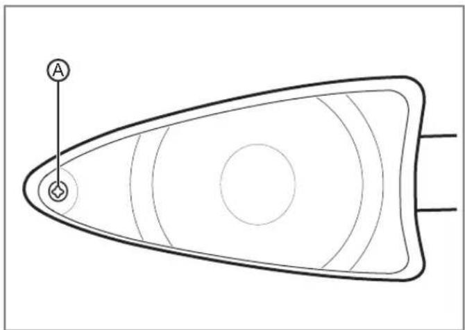
natural_image
Diagram of a symmetrical geometric shape with concentric circles and a labeled point A, no text or symbols present.Brake/Tail LED Replacement
The brake/tail LED is not serviceable. Please contact your Zero motorcycle dealer for replacement.
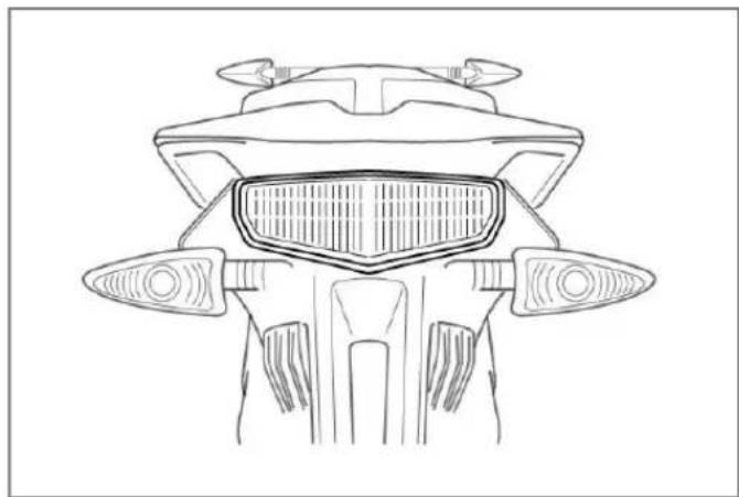
natural_image
Top-down line drawing of a motorcycle's front wheel and side brackets (no text or symbols)General Maintenance
Running Light Bulb Replacement
- Working from behind the headlight, remove the bulb socket (A) from the headlight by squeezing the metal clip.
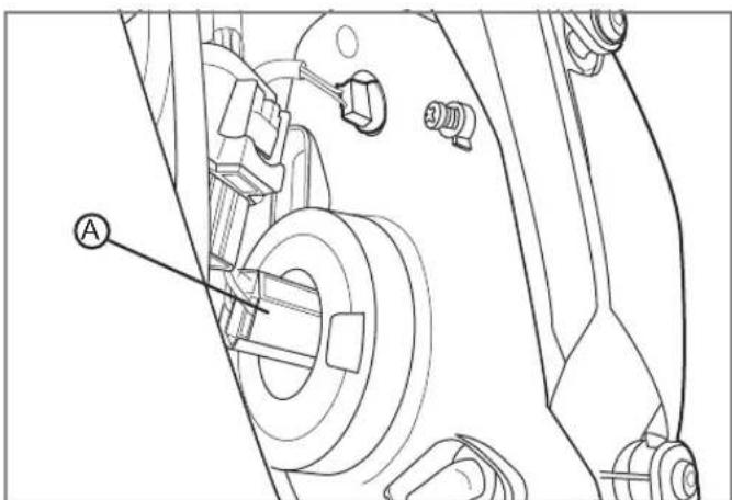
- Pull the old bulb straight out from the socket.
- Push the new bulb into the socket, and push the socket into the headlight.
General Maintenance
Cleaning
WARNING! Improper cleaning can damage electrical components, cowlings, panels, and other plastic parts. Do not use high pressure water or steam cleaners; they can cause water intrusion of bearing, seals, and electrical components. Avoid spraying water of great force around the instrument panel, power pack, or controller.
To prolong the life of your motorcycle it should be washed periodically. Regular cleaning, is an important factor in maintaining the value of your motorcycle. It also ensures that safety relevant parts remain in full working order.
If tar, bugs, or other similar deposits have accumulated, wash them off as soon as possible.
CAUTION: After cleaning and before starting your journey, always test the brakes.
Washing
WARNING! Do not use any harsh chemical products on plastic parts. Be sure to avoid using cloths or sponges which have been in contact with strong abrasive cleaning products, solvent or thinner, fuel (gasoline), rust removers or inhibitors, brake fluid, antifreeze or electrolyte.
Note: We recommend the use of a garden hose to wash your motorcycle. High-pressure washers (like those at coin-operated car washes) can damage certain parts.
- Gently wash your motorcycle with a sponge or a clean soft cloth, mild detergent, and plenty of water.
- Use care when cleaning the plastic parts (dash, fenders, and side panels), which can scratch easier than the other parts of your motorcycle.
- After washing, rinse your motorcycle thoroughly with plenty of clean water to remove any detergent residue.
- Dry your motorcycle with a chamois or a soft, dry towel.
- After cleaning, inspect for damage, wear or leaks.
After washing the motorcycle, allow all of the electrical components to dry prior to operation. If the motorcycle is ridden after being washed, apply both brakes several times in order to remove any moisture from the brake pads.
Wheels and tires
Avoid using strong acidic wheel cleaners, especially on spoked wheels. If such products are used on hard-to-remove dirt, do not leave the cleaner on the affected area any longer than instructed. Also thoroughly rinse the area off with water, immediately dry it, and then apply a corrosion protection spray.
Do not use products such as tire dressings on tires as this will deteriorate traction.
General Maintenance
Parking and Long Term Storage
- For planned long-term storage (more than 30 days), draining the power pack to a \~60% state of charge (SOC) and leaving the motorcycle unplugged is recommended.
- The power pack will drain extremely slowly over time. Check the SOC at least monthly and charge it back up to 60% if it has dropped below 30%. When you're ready to take your motorcycle out of storage to ride it again, plug it in for at least 24 hours to ensure optimal cell balanced is restored.
- To prolong the life of your power pack you should store your motorcycle in a cool area. Storing your motorcycle in a hot area will cause your power pack's life to be shortened.
For more information on the power pack and the electrical system see page 4.14.
Note: Never store your motorcycle at a SOC of less than 30%. Leaving the power pack discharged below 30% for a prolonged period of time could damage the power pack and void its warranty.
WARNING! Opening of the power pack is for trained Zero Motorcycles technicians. Please be aware that incorrect handling of a Zero power pack can be dangerous. DO NOT OPEN!
Zero Motorcycles Accessories
Zero motorcycle accessories are designed to complement and function with other systems on your motorcycle. Your dealer can accessorize the motorcycle using genuine Zero accessories.
A full line of parts, accessories, and apparel can be found on the Zero Motorcycles website.
Fuses
Whenever there is an excessive amount of current flowing through a circuit the fusible element will melt and create an open or incomplete circuit. Fuses are a one-time protection device and must be replaced each time the circuit is overloaded. Replace the fuse with one of equal current and voltage rating. If the fuse melts repeatedly, have the electrical system inspected by your dealer.
General Maintenance
12 Volt Fuse Center
The 12 volt fuse center is located underneath the seat.
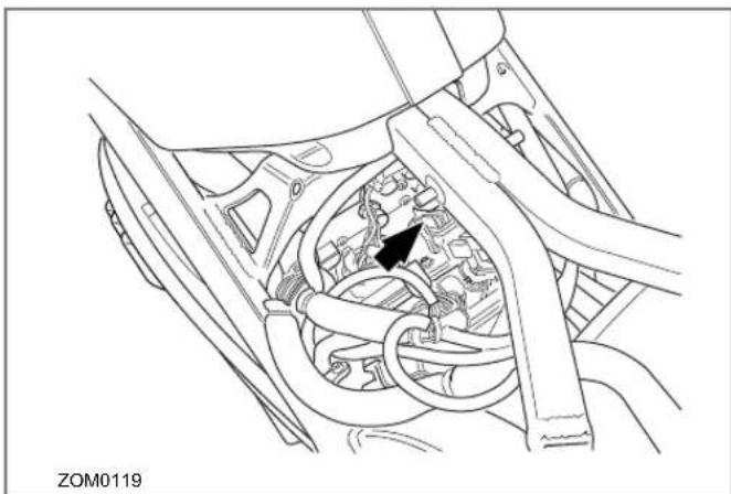
natural_image
Technical line drawing of a mechanical assembly with no visible text or symbolsThe fuse center (see arrow) has a protective cover that must first be removed to gain access to the fuses. To remove the cover, squeeze the tabs together and lift off the cover.
To access the 12 volt fuse center:
- Remove two bolts securing the seat to the motorcycle frame. Refer to Component Fasteners, page 5.5.
-
Pull the seat rearward to gain access to the fuse center.
-
Squeeze the tabs (A) on the fuse center to remove the cover.
- Replace the fuse(s).
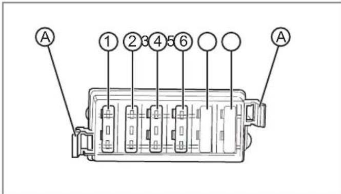
The 12-volt fuse values are listed below:
| FUSE | RATING CIRCUITS CONTROLLED | |
| 1 | 10A | Headlight |
| 2 | 10A | Accessory Port |
| 3 | 10A | Flash Lights, Turn Signals, Horn, Brake/Tail Light |
| 4 | 5A | Running Lights |
General Maintenance
High Voltage Fuse Center
The high voltage fuse center sits in front of the low voltage fuse center (in a cluster of four fuses).
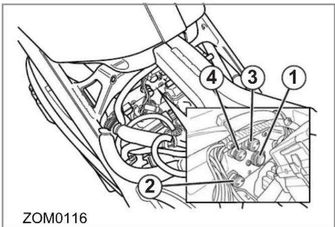
To access the high voltage fuse center:
- Remove the two bolts securing the seat to the motorcycle frame.
- Pull the seat rearward to gain access to the fuse center.
- Unscrew the fuse's cover.
- Replace the fuse.
The high voltage fuse values are listed below:
| FUSE RATING CIRCUITS CONTROLLED |
| 1 ATM30 Quick Charger |
| 2 ABC20A Charger |
| 3 ABC4A DC/DC Converter |
| 4 ABC4A Main Bike Board/Controller |
Follow the maintenance schedules on page 5.2. After a scheduled service or routine is performed, record the information on the chart below.
| DATE ITEM | SERVICE/ROUTINE DESCRIPTION | |
Notes
Electric Motorcycle Precautions
Your Zero motorcycle has high voltage components. The high voltage used by these components is dangerous and can cause personal injury, severe burns, electric shock and even fatal injury unless appropriate precautions are taken.
Always observe and obey the instructions on labels attached to components on the vehicle - they are there for your safety.
Do not touch, attempt to remove or replace any high voltage parts, wiring (identified by the orange outer sleeving) or connectors. If the motorcycle is involved in an accident do not touch any high voltage wiring connectors or the components connected to the wiring. If a motorcycle fire occurs, extinguish it with a Class D power-type fire extinguisher.
CAUTION! Your motorcycle uses high voltage. System components can be hot to touch during and after starting and when the motorcycle is shut off. Be careful of both the high voltage and the high temperature. Obey all labels that are attached to the motorcycle.
CAUTION! The motorcycles high voltage system has no user serviceable parts. Disassembling, removing or replacing high voltage components, cables or connectors can cause severe burns or electric shock that may result in serious injury or death. High voltage cables are colored orange for easy identification (see First Responder Information illustration at the back of this manual).
Troubleshooting Your Motorcycle
All of the motorcycles are carefully inspected before they are delivered. Even after the motorcycles are inspected, some technical issues can occur. The following information offers a guide to help you to identify an issue, and if possible, repair it yourself. If you are unable to solve an issue with your Zero S/DS electric motorcycle, take it to an authorized dealer at your convenience. If there is no dealer in your area call Zero Motorcycles Customer Service.
Troubleshooting
Battery Management System
The Battery Management System (BMS) is located inside the power pack and is fitted with a window (A) to provide visual notification about the status of the power pack. There are four LED lamps that will flash: one red and three green lamps. The window is located on the front of the power pack (behind the front wheel). See the next page for the meanings of these patterns.

natural_image
Technical line drawing of a mechanical assembly with labeled component A (no readable text or symbols)Troubleshooting
Understanding BMS Flash Code Patterns (Idle Mode)
In this mode the key is OFF and the power pack is not being charged (the BMS is only monitoring the battery).
| 1 RED | 2 GREEN | 3 GREEN | 4 GREEN | ON | OFF | MEANING | SOLUTION |
| √ | 50 ms | 5 sec | Healthy | BMS OK | |||
| √ | 50 ms | 60 sec | Pack Low | Charge power pack | |||
| √ | 50 ms | 1 sec | Number of Cell Packs Not Set | Contact Zero or the Dealer | |||
| √ | 50 ms | 1 sec | Self-Test Failed | Contact Zero or the Dealer | |||
| √ | 50 ms | 250 ms | Waiting for UART Input | Contact Zero or the Dealer |
Troubleshooting
Understanding BMS Flash Code Patterns (Charge Mode)
This mode is with the charging cord plugged into the AC power, and the key in the OFF position. During the Charging process, first all lights will flash. Next, lights 1 through 4 will flash depending on the power pack's state of charge.
| 1 RED | 2 GREEN | 3 GREEN | 4 GREEN | ON | OFF | MEANING | SOLUTION |
| 1 sec | 5 sec | Charge Complete | Unplug Charger | ||||
| Charging | |||||||
| 250 ms | 25% | Continue Charging | |||||
| 250 ms | 50% | Continue Charging | |||||
| 250 ms | 75% | Continue Charging | |||||
| 250 ms | 100% | Continue Charging | |||||
| Balancing | |||||||
| 500 ms | Power Pack Unbalanced | Let the Power Pack Cool Down | |||||
| 500 ms | |||||||
| Temperature Disable | |||||||
| 100 ms | 500 ms | Too Hot | Let the Power Pack Cool Down | ||||
Troubleshooting
Understanding BMS Flash Code Patterns (Run Mode)
In this mode, the key is in the ON position.
| 1 RED | 2 GREEN | 3 GREEN | 4 GREEN | ON | OFF | MEANING | SOLUTION |
| √ | 5 sec | 1 sec | 25% of Power Remaining | Charge Soon | |||
| √√5 sec 1 sec 50% of Power Remaining Charge Soon | |||||||
| √√√5 sec 1 sec 75% of Power Remaining Charge Soon | |||||||
| √ | √ | √ | √ | 5 sec | 1 sec | 100% of Power Remaining | OK |
Troubleshooting
Power Pack Empty
If the power pack is completely empty, an error-beep sounds and the BMS disables the throttle. You cannot ride the motorcycle until you recharge the power pack. If the Power Pack Empty error-beep still sounds after two hours of charging time, contact your dealer. Your power pack may need to be repaired or replaced.
Power Pack Full (High Power Pack-Voltage)
If the BMS detects that the power pack is already full, it disables any further charging to prevent damage to the power pack.
This is not an error-condition; it is the result of a successful charging cycle. There is no self-test flash code which reports this condition.
During an ordinary charging cycle, when the cells are balanced, the charger (not the BMS) senses that the power pack is full and terminates the charging cycle with a "green light." The BMS does have a redundant back-up mechanism to prevent overcharging of the power pack. If the charger fails to terminate a charging-cycle when the power pack is full, the BMS will terminate charging itself to prevent damage.
Power Pack Too Hot
The power pack contains internal temperature sensors. If the BMS measures excessive internal temperatures, it flashes an error code and disables the throttle. You cannot ride the motorcycle until the power pack cools down. Place the motorcycle in a cool, well-ventilated location and wait a few minutes before riding again. If the Too Hot error code still flashes after the power pack has had time to cool down, contact your dealer. Your power pack may need to be repaired or replaced.
Power Pack Unbalanced
The power pack contains many individual cells. The BMS continuously monitors the cells and tries to keep them all "in balance" (at the same level-of-charge). If any of the cells are grossly out-of-balance, the BMS flashes a Power Pack Unbalanced error code and disables the throttle. You cannot ride the motorcycle until the problem is resolved.
The solution to the problem is to plug in the charger and allow the power pack to charge for 72 hours. This allows the BMS to re-balance the cells in the power pack. If the Power Pack Unbalanced error code still flashes after the power pack has spent more than 72 hours charging, contact your dealer. Your power pack may need to be repaired or replaced.
Other Error-Flash Patterns
If the BMS in your power pack produces an error code which is not described in Understanding BMS Flash Code Patterns, then the power pack has encountered a serious internal hardware problem and must be repaired or replaced by a dealer.
BMS Error Beep Pattern
It is possible to encounter the power ON self-test result error-beeps from a badly malfunctioning or damaged power pack. If so, the user should return the power pack to Zero for repair or replacement.
| PATTERN WHEN MEANING | |||
| 3 Long | Pwr-onM-cmd | Fail Power ONself-test Mfg. test | |
Troubleshooting
Cold and Hot Weather Considerations
Cold Weather
Cold Weather operation of the motorcycle has no permanent impact on its battery pack/cells; however, the rider may see a reduction in range due to the effect cold temperature has on the amount of energy the pack/cells can release. The colder the weather, the greater the effect; so that, as compared to operation in 80°F (27°C) ambient, at 30°F(-1°C) ambient the rider could experience a temporary reduction in range of up to 30%.
In extreme cold weather the motorcycle may also experience a temporary reduction in power and, correspondingly, achieved top speed.
It is not recommended that the motorcycle be ridden while its battery temperature is below 23^(-5^) . If it is, its battery needs to be put on the charger at a temperature above 32^(0^) as soon as the ride is concluded. It is worth noting that the Battery Management System (BMS) will not allow the battery to be discharged below -22^(-30^) , which is the absolute lowest discharge temperature prescribed by the cell manufacturer.
Storage of the motorcycle for the winter in a non-heated garage is acceptable, as long as:
- the coldest temperature in the garage does not fall below -31°F (-35°C).
- the battery is drained to a \~60% state of charge prior to storage and you check its state of charge at least monthly and charge it back up to 60% if it has dropped below 30%.
- the battery is initially topped off at a temperature above 32^ F ( 0^ C).
Storage temperatures below -31°F (-35°C) may result in accelerated permanent decay of the battery performance, and hence it is not recommended. Above this temperature and following the long-term storage guidelines (see "Parking and Long Term Storage", on page 5.22) will ensure the battery survives winter storage with no permanent damage, even if the temperatures dip well below freezing for weeks at a time. Note that, while charging, to prevent battery damage, the BMS will prevent the charger from charging the battery at a temperature below 32°F (0°C). Again, as long as the battery was drained to \~60% state of charge and kept above 30% state of charge through the winter at temperatures above -31°F (-35°C), the battery will be safe from damage.
Troubleshooting
Hot Weather Operation
Operation of the motorcycle in hot temperatures should not result in any noticeable performance changes. However, the BMS will not allow motorcycle operation and its associated battery discharge above 140^ F ( 60^ C), as measured at the battery.
In hot temperatures (greater than 110^ F ( 43^ C) for 2013 Model Year), the charger reduces its charge current to the battery, increasing charge time accordingly; the hotter the ambient temperature, the greater the effect. Above a battery temperature of 131^ F ( 55^ C), the BMS will no longer allow charging.
Note: Storing the motorcycle or its battery in direct sunlight in ambient temperatures above 105^ F ( 41^ C) may result in accelerated permanent decay of battery performance, and hence it is not recommended.
Troubleshooting
Safety Interlocks
If the BMS detects a serious internal fault, it can take either or both of two actions to prevent damage to the power pack:
- Throttle Disable. The BMS disables the throttle if the power pack is empty, or if the BMS detects certain serious internal problems. You cannot ride the motorcycle until the problem is resolved.
- Charger Disable. The BMS prevents charging if it detects certain serious internal problems - even if the power pack is connected to a charger and plugged in to AC power. The power pack cannot be charged until the problem is resolved.
Throttle Disable Interlock
The BMS communicates with the main motorcycle control module. The BMS can send a signal to the main motorcycle controller requesting that the throttle control on the motorcycle be disabled. When the throttle control is disabled, the motor will not deliver power to the rear wheel, and the motorcycle cannot be ridden.
If the throttle is disabled while riding, the motorcycle will cease to provide power, and the operator must pull over to a safe location.
All conditions which would cause the BMS to disable the throttle are also signaled by a flash code pattern at self-test. If you suspect that the BMS has disabled the throttle control on your motorcycle, turn the key switch OFF and back ON again to enter self-test mode. The flash code pattern from the BMS reports any of the error conditions which would cause the BMS to disable the throttle.
Each of these conditions, the associated self-test flash code pattern, and the suggested remedies are discussed in Understanding BMS Flash Code Patterns on page 6.4.
- Power Pack Empty
- Too Hot
• Power Pack Unbalanced
Charger-Disable Interlock
When the charger is attached and plugged in to AC power, the BMS communicates with the charger. The BMS can send a signal to the charger requesting that charging terminates immediately. When the charger is disabled, the indicator lights on the charger displays that charging has stopped.
There are two conditions that cause the BMS to disable charging:
- Too hot
The BMS detects an internal power pack temperature above 131^ F ( 55^ C).
- Too cold
The BMS detects an internal power pack temperature below 32^(0^) .
Troubleshooting
System Warning Indicator
If a fault has been detected, count the number of times the red LED (A) flashes.
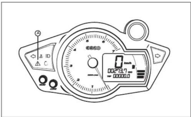
Refer to the table starting on the next page for possible causes and solutions to the issue.
Troubleshooting
| NUMBER OF RED FLASHES CAUSE SOLUTION | |||
| 1 |  | Motor Stop Switch Disabled or Kickstand Switch Disabled | Motor stop switch is in the OFF position. Press the motor stop switch ON button. Kickstand is down. Raise kickstand. |
| 2 Indication Airways ON Contact Zero or your dealer. | |||
3 Self-  Unabling charger. Unabling charger. | |||
| 4 Charger Connected | Throttle is ON or throttle/connection is bad. Verify throttle action and/or check connection. | ||
5 High  Enable Enable | Could not pre-charge motor controller. Contact your dealer. | ||
| 6 Low Power Pad/Disable Change Power Pack Before Riding. | |||
7 Conta  r Contact Zero or your dealer. r Contact Zero or your dealer. | |||
| 8 | Controller Area Network (CAN) Error | Contact Zero or your dealer. | |
| 9 |  | Battery Management System (BMS) Throttle Disable | Contact Zero or your dealer. |
| 10 Throttle Out of Range | Bad throttle or connections. Verify throttle action and/or check connection. | ||
11 Motc  ature Sensor Out of Range ature Sensor Out of Range | Bad motor temperature sensor or connections. Replace temperature sensor and/or check connections. | ||
Troubleshooting
| NUMBER OF RED FLASHES CAUSE SOLUTION | |||
| 12 MBBVillageErrorContactZero or your dealer. | |||
| 13 Board temperature Warning | Board may have overheated. Let the motorcycle cool down. | ||
| 14 Current Sensor Error | Problem with current sensor or connection. Contact your dealer. | ||
| 15 Board temperature Sensor Out of Range | Problem sensing temperature of board. Contact your dealer. | ||
| 16 High Current Disable | Turn the ignition OFF and ON. If problem persists contact Zero or your dealer. | ||
| 17 Temperature Protection Error | Turn the ignition OFF and allow to cool off and then restart. If problem persists contact Zero or your dealer. | ||
| 18 Throthe Output Error | Turn the ignition OFF and ON. If problem persists contact Zero or your dealer. | ||
| 19 Kickstand Error | Bad kickstand switch or connection. Replace kickstand switch and/or check connection. | ||
| 20 Miscellaneous Error Contact Zero or your dealer | |||
Troubleshooting
General Troubleshooting
| SYMPTOM POTENTIAL CAUSE POTENTIAL SOLUTION | ||
| Motorcycle does not turn on Power Pack not charged. Key not properly engaged.Motor stop switch turned OFF. Fault code set. | Charge Power Pack. Recheck key in ignition, turn OFF/ON again. Press the motor stop Switch ON button. See Charge Fault Code chart onpage 6.3or see Understanding BMS Flash Code Patterns starting onpage 6.3. | |
| Charger not working | A/C power missing fault code set | Check A/C outlet for power, A/C source check fuse/voltage.See Charge Fault Code chart onpage 6.4or see Understanding BMS Flash Code Patterns onpage 6.4. |
| Handlebars wobbly (shimmy) | Incorrect tire pressure | Inflate to correct tire pressure. Seepage 5.14. |
| Deformed front tire Replace/balance front tire with the same tire supplied from the factory. | ||
| Bald tire (excess wear) Replace/balance tire with the same tire supplied from the factory. | ||
| Loose headset bearings Inspect the headset for wear or damage, replace any worn or damaged parts. Tighten the headset pre-load. | ||
Notes
Zero Motorcycles Warranties
Zero Motorcycles Inc. expressly warrants all 2013 Zero manufactured S and DS models from defects in material and workmanship to the original owner, under normal operating conditions and according to proper use, for 2 years (unlimited miles) from the “In Service Date,” which is the date your Zero Motorcycles dealer performed a Pre-Delivery Inspection (P.D.I) on the Zero.
These warranties are transferable and subject to a \$50 processing fee and a new registration card to subsequent owners.
Standard Warranty
The standard warranty covers parts, standard shipping and labor for all major components, defined herein as including the motor, motor controller, power pack, frame, swingarm, fork, rear shock, brake assemblies, wheels, and electrical sub-assemblies.
This warranty covers Zero manufactured accessories installed at the time of purchase.
Standard Warranty Exclusions
This warranty does not apply to tire wear, sprocket and belt condition, brake pads or rotors, fork seals, grips, foot pegs, the seat, or any other parts subject to normal wear and tear. Wheels are excluded from this standard warranty on off-road bikes once they have been ridden.
This standard warranty excludes aftermarket accessory kits which may be subject to their own warranties.
This standard warranty excludes parts and components damaged by use or operation under abnormal circumstances or contrary to the requirements described in the owner's manual, or damaged by improper use or accidents.
Racing or competitive use voids this warranty.
Modifications or alterations to major components of the manufacturer's original product or its sub-components void all warranties. Zero Motorcycles Inc. assumes no liability for any misuse or improper operation of Zero motorcycles.
Under this limited warranty and liability agreement, Zero Motorcycles Inc. shall have no obligation and the purchaser shall have no remedy against Zero Motorcycles Inc. and its officers and/or agents for any damages, including but not limited to incidental, consequential, special, punitive damages arising from direct or indirect
Warranty Information
injury to person or property, or any other loss, whether or not occasioned by negligence or otherwise on the part of Zero Motorcycles Inc.
Disclaimers Applicable to Standard Warranty
The purchaser acknowledges that there is an inherent risk in the operation of Zero motorcycles and all other Zero Motorcycles Inc. products, and herewith assumes liability for any injury arising from all operation of any Zero Motorcycles Inc. product. The original registered owner or subsequent registered transferee as documented on the Zero motorcycle warranty registration form will indemnify and hold Zero Motorcycles Inc. harmless and take full responsibility for conveying all safety warnings, instructions and limited warranty if the unit is sold, loaned or otherwise transferred to other persons, and will indemnify Zero Motorcycles Inc. from any claims against it for the original owner's failure to do so.
Zero Motorcycles Inc. does not assume or authorize anyone to assume for them any other obligation. Some states, provinces, or countries do not allow limitations on how long an implied warranty lasts, so the above limitation may not apply to you.
Zero Motorcycles Inc. assumes no responsibility for incidental, consequential or other damages including but not limited to: expense of returning the Zero product to a
certified service center, expense of delivering it back to the owner, mechanic's travel, time, communication charges, rental of a like product during the time the warranty service is being performed, travel, loss or damage to personal property, loss of revenue, loss of use of the product, loss of time, or inconvenience. Some states, provinces, or countries do not allow limitations so the above limitation may not apply to you.
Zero Motorcycles Inc. reserves the right to change or improve the design of any electric motorcycle product without assuming any obligation to modify any product previously manufactured.
These warranties give you specific legal rights, and you also have other rights, which vary from state to state, province to province, and country to country.
These warranties apply to all Zero products manufactured by Zero Motorcycles Inc.
Normal operating conditions require routine care and maintenance by the purchaser of the Zero Motorcycles Inc. electric motorcycle and power pack.
Proper Use
For the purposes of these warranties, ‘proper use’ means only the use of a motorcycle in the manner intended with proper safety equipment as described in the Owner's Manual in accordance with local regulations. ‘Proper use’ also means charging the Power Pack after each use and storing it in a fully charged state, or recharging it every 30 days, or keeping it on the charger when in storage or out of regular use.
Purchaser's Responsibilities
Read and understand the Owner's Manual and all product warnings before operating your Zero Motorcycles Inc. electric motorcycle. Serious injury or death may result from improper operation or failure to observe warnings and safety instructions on any motorized motorcycle or vehicle.
Submit the warranty registration card for your Zero motorcycle within the required time period as printed on the registration card.
Perform routine care and maintenance of your Zero
Motorcycles Inc. electric motorcycle and power pack as detailed in the Owner's Manual.
The rider is responsible for learning and obeying all federal, state, province, country, and local laws governing the operations of an electric motorcycle.
Always wear a helmet, goggles, appropriate boots, and all other appropriate safety equipment when operating a motorcycle.
Warranty Information
Warranty Procedures
Warranty services may be obtained by contacting your local Zero Motorcycle dealer; please see the locator on www.zeromotorcycles.com for the nearest location. In the event that a dealer is not in your state, province, or country, you can contact Zero Motorcycles Inc. directly at (888) 786-9376 or via e-mail at support@zeromotorcycles.com.
Service may also be available from a local Zero Motorcycles Certified Service Center; please see the locator on www.zeromotorcycles.com for the nearest location.
In any written or telephonic communication, please state the specific nature of and any circumstances leading to the problem.
North America and Canada:
Zero Motorcycles Inc.
380 El Pueblo Road
Scotts Valley, CA 95066
USA
Europe:
Zero Motorcycles BV
Fluorietweg 12D
Alkmaar, 1812 RR
NL
(U.S. and International Patents and Trademarks Pending)
Transfer Of Ownership And Warranty
When it comes time to sell your Zero motorcycle, please visit the Zero Motorcycles website and access the Owner Resources section to fill out the on-line transfer of ownership and warranty form. This must be performed to allow Zero Motorcycles the ability to contact the new owner in the unlikely event of a safety related issue. Use the email address below or feel free to contact the Zero Motorcycles Customer Service department for assistance.
Zero Motorcycles Inc.
380 El Pueblo Road
Scotts Valley, CA 95066
USA
Monday-Friday 8am to 5pm (Pacific Time)
E-mail: support@zeromotorcycles.com
Customer Information
Customer Assistance
Please have the following available when contacting Zero Motorcycles Inc. as they are essential to effectively and efficiently answer your questions or resolve your concerns.
- Owner's name and address
- Owner's telephone number
• Vehicle identification number (VIN) - Date of purchase
- Motor serial number (if visible)
An owner information chart is provided on page 1-3 to record this information.
Zero Motorcycles Inc. can be contacted as follows:
Zero Motorcycles Inc.
380 El Pueblo Road
Scotts Valley, CA 95066
USA
Monday-Friday 8am to 5pm (Pacific Time)
E-mail: support@zeromotorcycles.com (24 hours)
For 24 hour updates and additional information about your motorcycle, visit the Owners Resources section of the Zero Motorcycles website:
www.zeromotorcycles.com/owner-resources/
Reporting Safety Defects
If you believe that your vehicle has a defect which could cause a crash or could cause injury or death, you should immediately inform the National Highway Traffic Safety Administration (NHTSA) in addition to notifying Zero Motorcycles Inc.
If NHTSA receives similar complaints, it may open an investigation, and if it finds that a safety defect exists in a group of vehicles, it may order a recall and remedy campaign. However, NHTSA cannot become involved in individual problems between you, your dealer, or Zero Motorcycles Inc.
To contact NHTSA, you may call the Vehicle Safety Hotline toll-free at:
1-888-327-4236 (TTY: 1-800-424-9153); go to http://www.safercar.gov; or write to:
Administrator
National Highway Traffic Safety
1200 New Jersey Avenue SE
Washington, DC 20590
You can also obtain other information about motor vehicle safety from:
http://www.safercar.gov
Notes
Index
A
Accessories 5.26
B
Brake/Tail Light Bulb Replacement 5.23
Brakes 5.10
Brake Fluid Level Inspection....5.11
Brake Pad Inspection....5.13
Braking....4.14
DOT 4 brake fluid....5.12
Front Brake 5.11
Rear Brake....5.12
C
Charging
CHAdeMO Charger....1.11, 4.13
Charging the Power Pack....4.9
Cleaning Your Motorcycle 5.25
Contact information
NHTSA....7.7
D
Drive Belt....5.15
Checking Drive Belt Tension....5.15
Drive Chain....5.17
Cleaning 5.17
Lubricating 5.18
E
Emissions Information 1.14
F
First Time Set-Up....4.1
Fuses....5.26
High Voltage Fuse Center....5.28
G
General Operation 4.3
Key Switch/Steering Lock Positions....4.4
Pre-Ride Inspection....4.3
General Safety Precautions....2.1
General Troubleshooting 6.15
H
Headlight Alignment ....5.20
Bulb Replacement....5.21
|
Important Operating Information....2.2
Inspection
Pre-Ride....4.3
Instrument Panel....3.8
INDEX.1
Index
K
Keys
Replacement Code Number 1.4
L
Location Of Important Labels 2.3
M
Maintenance Schedule....5.2
Maximizing Range....1.11
Motor Serial Number 1.4
0
Operating Your Motorcycle....4.14
Braking....4.14
Stopping....4.14
Owner Information Record 1.3
Owner's Responsibilities ....5.1
P
Parking 5.26
Parts/Maintenance Items....5.1
Performance Level Switch....3.11
ECO Position 3.11
SPORT Position....3.11
Power Pack 5.9
Plug in Your Z-Force Power Pack....1.2
Serial Number....1.4
Pre-Ride Inspection....4.3
Public Charging Stations ....1.11
Q
Quick Charging....4.11
R
Reporting safety defects....7.7
S
Safe Riding Information....1.2
Safety Interlocks....6.10
Serial Number
Motor....1.4
Power Pack....1.4
Smartphone Application 3.15
State of Charge (SOC) 3.15
Storage
Long Term....5.26
Suspension
Front....5.13
Rear 5.13
Suspension Adjustment....4.16
Front Fork Adjustment 4.17
Rear Shock Adjustment 4.18
Index
Suspension settings
Front (Factory) 4.17
Rear (Factory)....4.22
T
Technical Specifications
Zero DS Technical Specifications ....1.8
Zero S Technical Specifications....1.6
Tire Inflation....5.14
Transporting 1.15
Troubleshooting
Battery Management System (BMS)......6.2
Charge Mode 6.4
Run Mode 6.5
Turn Signal Light Bulb Replacement....5.23
U
Unpacking Your Zero Motorcycle 4.2
Recycling 4.2
v
Vehicle Identification Number (VIN)
Location 1.4
Understanding Your VIN Number 1.5
Vehicle Range 1.10
W
Warning Lights....3.8
Warranty 7.1
Disclaimers Applicable to Standard Warranty......7.2
Standard....7.1
Standard Warranty Exclusions....7.1
Transfer Of Ownership And Warranty....7.5
Wheels And Tires 5.14
Notes
INDEX.4
First Responder Information - High Voltage Components Locations

WARNING

DO NOT CUTDO COLOREDOLO ZONESZONES

NEVER cut high voltage components or cabling. Cutting could result in serious injury or death.

High voltage cables and components may remain energized for up to 10 seconds after disabling.

HIGH-VOLTAGE
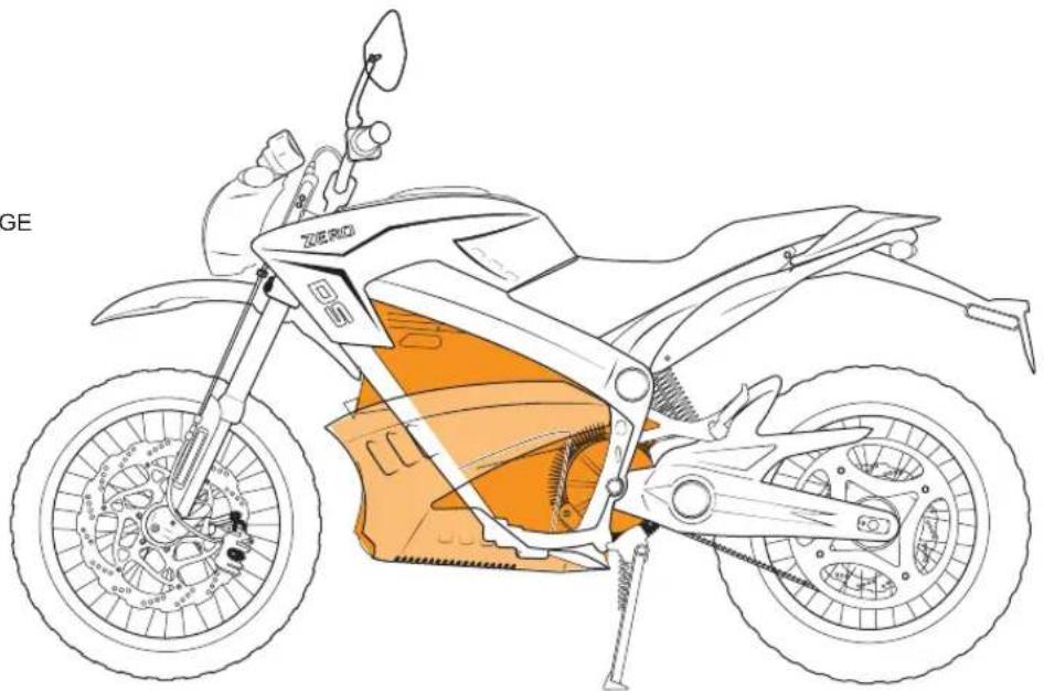
natural_image
Line drawing of a Zero Moto motorcycle showing front wheel, rear wheel, and internal gear assembly (no text or symbols)

WWW.ZEROMOTORCYCLES.COM
- Identification Numbers.... 1.3
- General Information 1.6
- Safety Information 2.1
- General Safety Precautions.... 2.1
- Location of Important Labels 2.3
- Controls and Components 3.1
- Controls and Components.... 3.1
- Starting and Operating 4.1
- Starting and Operating...... 4.1
- General Operation 4.3
- Table Of Contents
- Maintaining Your Motorcycle.... 5.1
- Maintaining Your Motorcycle ....5.1
- Power Pack 5.9
- General Maintenance ....5.10
- Service Record 5.29
- Troubleshooting.... 6.1
- Warranty and Customer Information...... 7.1
- Warranty Information.... 7.1
- Customer Information.... 7.6
- Index
- First Responder Information - High Voltage Components Locations
- An Important Message To You From Zero Motorcycles
- About This Manual
- Locating and referencing information
- Introduction
- Useful Information For Safe Riding
- Unplug Your Z-Force® Power Pack™
- Owner Information
- Identification Numbers
- Power Pack Serial Number
- Motor Serial Number
- Key Code Number
- Vehicle Identification Number (VIN)
- Chassis Number
- VIN Break Down
- General Information
- Technical Specifications
- Zero S
- Vehicle Range
- Public Charging Stations
- CHAdeMO Charger
- Maximizing Your Range
- How to Predict the Range
- Emissions Information
- Transporting
- Notes
- General Safety Precautions
- Important Operating Information
- Location of Important Labels
- Anti-Tamper Control Label (Europe only)
- Controls and Components
- Motorcycle Controls
- A.Mirrors
- Performance Level Switch
- C.Key Switch/Steering Lock
- E.Front Brake Fluid Reservoir
- FFront Brake Lever
- G.Throttle Control
- H.Motor Stop Switch
- Left Handlebar Control
- A.Headlight
- Turn Signals
- C.Brake/Tail Light
- D.AC Charger Power Connection
- E.Integrated Power Pack Charger
- FKickstand
- G.Kickstand Switch
- H.Rear Turn Signal
- A.Left Indicator Turn Signal
- Temperature Lamp
- High Beam Indicator
- D.Tachometer/Speedometer
- E.Main Power Indicator
- FCharge Indicator
- G.Right Turn Signal Indicator
- H.Odometer
- Trip Odometer
- J.Adjust Button
- K.Select Button
- L.Charging Indicator
- M.System Warning Indicator
- Performance Level Switch
- Handlebar Controls
- Flash-to-Pass
- B.Headlight High/Low Beam Switch
- C.Front Brake Lever
- D.Throttle Control
- E.Motor Stop Switch
- F.Turn Signal Switch
- G.Horn Button
- Tank Bag
- Smartphone Application
- First Time Set-Up
- Starting and Operating
- Unpacking Your Zero Motorcycle
- Outer Box Cover
- Inner Assembly
- Recycling
- General Operation
- Pre-Ride Inspection
- Steering Lock
- OFF Position
- ON Position
- Power Pack
- Battery Management System (BMS)
- Add On Electrical Equipment
- Power Pack Charger
- Charging the Power Pack
- Quick Charging (Off Board Accessory Charger)
- Quick Charger LED Indicators
- A.Ammeter
- B.80% Charge
- C.100% Charge
- D.AC ON
- E.Fault
- Operating Your Motorcycle
- Starting
- Braking
- Stopping Your Motorcycle
- Temperature Indicator
- Front Suspension Adjustment
- Bleed Screw
- Rebound Damping
- Compression Damping
- Factory Supplied Front Suspension Settings
- Rear Shock Adjustment
- Spring Adjustment
- Spring Pre-load Adjustment
- Rebound Adjustment
- Compression Adjustment
- Factory Supplied Rear Suspension Settings
- Owner's Responsibilities
- Parts/Maintenance Items
- Maintaining Your Motorcycle
- Maintenance Schedule
- Component Fasteners
- Handlebars
- General Maintenance
- Brakes
- Front Brake Pads
- Rear Brake Pads
- Brake Fluid Level Inspection
- Rear Brake
- Brake Pad Inspection
- Suspension
- Front
- Rear
- Wheels And Tires
- Tire Inflation
- Drive Belt
- Checking Drive Belt Tension
- Drive Belt Adjustment Procedure
- Drive Chain (Optional)
- Cleaning The Drive Chain
- Lubricating The Drive Chain
- Checking the Drive Chain
- Adjusting the Drive Chain
- Headlight Alignment
- Headlight Bulb Replacement
- Turn Signal Light Bulb Replacement
- Brake/Tail LED Replacement
- Running Light Bulb Replacement
- Cleaning
- Washing
- Parking and Long Term Storage
- Zero Motorcycles Accessories
- Fuses
- Volt Fuse Center
- High Voltage Fuse Center
- Electric Motorcycle Precautions
- Troubleshooting Your Motorcycle
- Troubleshooting
- Battery Management System
- Understanding BMS Flash Code Patterns (Idle Mode)
- Understanding BMS Flash Code Patterns (Charge Mode)
- Understanding BMS Flash Code Patterns (Run Mode)
- Power Pack Empty
- Power Pack Full (High Power Pack-Voltage)
- Power Pack Too Hot
- Power Pack Unbalanced
- Other Error-Flash Patterns
- BMS Error Beep Pattern
- Cold and Hot Weather Considerations
- Cold Weather
- Hot Weather Operation
- Safety Interlocks
- Throttle Disable Interlock
- Charger-Disable Interlock
- System Warning Indicator
- Zero Motorcycles Warranties
- Standard Warranty
- Standard Warranty Exclusions
- Warranty Information
- Disclaimers Applicable to Standard Warranty
- Proper Use
- Purchaser's Responsibilities
- Warranty Procedures
- Transfer Of Ownership And Warranty
- Customer Information
- Customer Assistance
- Reporting Safety Defects
- A
- B
- C
- D
- E
- F
- G
- H
- |
- K
- L
- M
- 0
- P
- Q
- R
- S
- Suspension settings
- T
- U
- v
- W
- WARNING
Brand : Zero
Model : DS (2013)
Category : Motorcycle