MX (2010) - Motorcycle Zero - Free user manual and instructions
Find the device manual for free MX (2010) Zero in PDF.


| Brand | Zero |
| Model | MX (2010) |
| Category | Motorcycle |
| Product Type | Electric Dirt Bike |
| Motor Type | Brushless DC Motor |
| Battery Capacity | 2.8 kWh (Lithium-ion) |
| Charge Time | Approx. 2 hours (standard charger) |
| Range (per charge) | Up to 1 hour of trail riding |
| Max Power | 23 hp (17 kW) |
| Top Speed | 105 km/h (65 mph) |
| Weight (dry) | 110 kg (242 lb) |
| Seat Height | 890 mm (35 in) |
| Ground Clearance | 280 mm (11 in) |
| Brakes | Front: 240 mm disc / Rear: 220 mm disc |
| Suspension Front | 41 mm inverted fork, adjustable |
| Suspension Rear | Progressive link with piggyback shock, adjustable |
| Frame | Aluminum perimeter |
| Tire Size Front | 2.75-21 |
| Tire Size Rear | 4.00-18 |
| Key Features | Electric silent ride, zero emissions, low maintenance, regenerative braking |
| Maintenance | Check tire pressure, chain lubrication, brake pads, battery condition, firmware updates |
| Safety | Wear helmet, goggles, gloves, boots; avoid water immersion; use original charger |
| Spare Parts & Repairability | Contact Zero Motorcycles dealer for genuine parts; battery pack not user-serviceable |
Frequently Asked Questions - MX (2010) Zero
User questions about MX (2010) Zero
0 question about this device. Answer the ones you know or ask your own.
Ask a new question about this device
Download the instructions for your Motorcycle in PDF format for free! Find your manual MX (2010) - Zero and take your electronic device back in hand. On this page are published all the documents necessary for the use of your device. MX (2010) by Zero.
USER MANUAL MX (2010) Zero
2010 OWNER'S MANUAL
ZERO MX™
ZERO X™
ZERO
MOTORCYCLES
Table Of Contents
Introduction 1-1
An Important Message To You From Zero...... 1-1
Introduction....1-1
Index 1-1
Useful Information For Safe Riding 1-2
Plug In Your Power Pack 1-2
Owner Information 1-3
Production Identification Number (PIN) .....1-4
PIN Location....1-4
PIN Break Down 1-4
General Information 1-6
Zero X Technical Specifications 1-6
Zero MX Technical Specifications 1-7
Vehicle Range 1-9
Optimizing Your Range By Adapting
Your Riding Style.... 1-9
Public Charging Stations 1-9
Emissions Information 1-10
Transporting 1-10
Safety Information 2-1
General Safety Precautions 2-1
Important Operating Information 2-2
Location Of Important Labels 2-3
Power Pack Information Label ......2-4
Throttle And Speed Control Label 2-5
Controls And Components 3-1
Motorcycle Controls 3-1
Right Side View 3-2
Instrument Panel 3-3
Speed Control Switch 3-3
Main Power Indicator 3-4
Energy Gauge 3-4
Torque Control Switch 3-4
Handlebar Controls 3-5
Left Handlebar Control 3-6
Right Handlebar Control 3-6
Starting And Operating 4-1
First Time Set-Up 4-1
Uncrating Your Motorcycle 4-2
General Operation 4-4
Pre-Ride Inspection 4-4
Key Switch Positions 4-5
Power Pack 4-5
Operating Your Motorcycle....4-15
Suspension Adjustment 4-16
Maintaining Your Motorcycle ....5-1
Owner's Responsibilities 5-1
Bolt Torque Table 5-2
Power Pack 5-5
General Maintenance 5-6
Motor 5-6
Brakes 5-6
Suspension 5-6
Wheels And Tires 5-7
Tire Inflation 5-8
Chain 5-8
Cleaning 5-11
Parking And Long Term Storage 5-12
Maintenance Schedule....5-13
Accessories 5-16
Fuses 5-16
Troubleshooting 6-1
Power Pack And Charger 6-1
Understanding Beep Sequences 6-3
Safety Interlocks 6-6
General Troubleshooting 6-11
Warranty/Customer Assistance 7-1
Customer Assistance 7-1
Warranty Information 7-2
Zero Motorcycles Limited Warranties....7-3
Standard Warranty....7-3
Extended Warranty 7-4
No Fault Warranty 7-5
Disclaimers Applicable to Standard
Warranty, Extended Warranty and
No Fault Warranty 7-5
Proper Use....7-6
Purchaser's Responsibilities....7-7
Warranty Procedures 7-7
Transfer Of Ownership And Warranty .....7-8
An Important Message To You From Zero
Congratulations and thank you for purchasing the 2010 Zero X/MX electric motorcycle; we welcome you to the community of Zero Motorcycle riders. This manual is designed to provide you with a better understanding of the operation, inspection, and basic maintenance requirements of this motorcycle. Zero continually seeks advancements in product design and quality. Therefore, this manual contains the most current product information available at the time of printing. Because of this, your motorcycle may differ from the information supplied in this owner's manual. No legal claims can be made on the basis of data in this manual. When it comes time to sell your Zero motorcycle, please remember to hand over this manual; it is, by law, an important part of the vehicle. If you have any questions concerning the operation or maintenance of your motorcycle, please contact Zero at support@zeromotorcycles.com.
Introduction Index
A good place to locate information about the motorcycle is in the index in the back of the manual. The terms "right" or "left" refer to the rider's right or left, when sitting on the motorcycle.
Useful Information For Safe Riding
This manual contains the word CAUTION to tell about something that could hurt you or others. It also contains the word WARNING to tell about things that could damage your motorcycle.
CAUTION: Please read this manual carefully and completely before operating this motorcycle. Do not attempt to operate this motorcycle until you have attained adequate knowledge of its controls and operating features, and until you have been trained in safe and proper riding techniques. Regular inspections and careful maintenance, along with good riding skills, will help you to safely enjoy the capabilities and the reliability of this motorcycle. Disregarding them may render the warranty invalid.
Plug In Your Power Pack
WARNING: Proper care of the motorcycle's power pack is essential! When not in use, the power pack should be left on the charger, even if fully charged. Failure to do so could damage the power pack and therefore void your battery warranty. See page 4-5 for other important information about the power pack.
Owner Information
Record important information here pertaining to your motorcycle. When contacting your Certified Service Center (CSC) you may need to provide this information.
CSC Information Motorcycle Information
Address ____ ____
PIN
Telephone No. ____ E-mail ____
Model ____
Battery Serial Number ____ ____
Date of Purchase ____
Production Identification Number (PIN)

See Location Of Important Labels on page 2-3.
PIN Break DownPIN Location
The PIN is a 17-digit number stamped on the head tube of the frame. Do not alter or remove this as it is the legal identifier for your motorcycle.
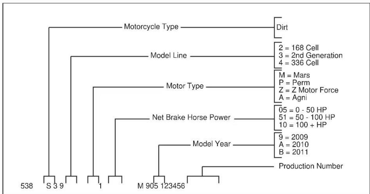
flowchart
graph TD
    A["S 3 9"] --> B["1"]
    B --> C["M 905 123456"]
    C --> D["Model Year"]
    D --> E["Net Brake Horse Power"]
    E --> F["Motor Type"]
    F --> G["Motor Line"]
    G --> H["Motorcycle Type"]
    H --> I["Dirt"]
    H --> J["2 = 168 Cell\n3 = 2nd Generation\n4 = 336 Cell"]
    H --> K["M = Mars\nP = Perm\nZ = Z Motor Force\nA = Agni"]
    H --> L["05 = 0 - 50 HP\n51 = 50 - 100 HP\n10 = 100 + HP"]
    H --> M["9 = 2009\nA = 2010\nB = 2011"]
    H --> N["Production Number"]
General Information
Zero X Technical Specifications
| MOTOR | |
| Type Brushed per | manent magnetic electric |
| Motor | • Sport-Mars• Extreme-Perm |
| Torque 67.7 N | •m (50 lb ft) |
| Peak Horsepower | 23 |
| Peak Electrical Input | 17,400 Watts |
| POWER SYSTEM | |
| Type Patent-pending lithium ion array | |
| Capacity 2 kwh (58 V @ 35 Ah) | |
| Range Up to 2 hours or 64 km (40 miles) | |
| Recharge Time Less than 2 hours | |
| Input Standard 1 | 10 V AC or 220 V AC |
| DRIVETRAIN | |
| Transmission Clutch | less one speed |
| Drive System | • Sport-12T/71T, 420 Chain• Extreme-15T/71T, 420 Chain |
| CHASSIS/SUSPENSION/BRAKES | |
| Front Suspension Travel | 200.7 mm (7.9 in) |
| Rear Suspension Travel | 215.9 mm (8.5 in) |
| Front Brakes | 4 Piston Hydraulic, Stainless Rotor, Hand Actuated |
| Rear Brakes | 4 Piston Hydraulic, Stainless Rotor, Hand Actuated |
| Front Tire | 24 x 3.0 in |
| Rear Tire | 17 x 3.5 in |
Zero MX Technical Specifications
| DIMENSIONS | |
| Wheel Base 137.2 cm (54 in) | |
| Seat Height 88.3 cm (34.8 in) | |
| Rake 23 degrees | |
| WEIGHT | |
| Frame 5.9 kg (13 pounds) | |
| Power Pack 20.9 kg (46 pounds) | |
| Curb Weight 73.0 kg (161 pounds) | |
| Total Weight Power Pack | 52.2 kg (115 pounds) |
| ECONOMY | |
| Typical Cost to Recharge | Less than $.01 per mile or kilometer |
| MOTOR | |
| Type Brushed per | manent magnetic electric |
| Motor | • Sport-Mars• Extreme-Perm |
| Torque 67.7 N | •m (50 lb ft) |
| Peak Horsepower | 23 |
| Peak Electrical Input | 17,400 watts |
| POWER SYSTEM | |
| Type | Patent-pending lithium ion array |
| Capacity | 2 kwh (58 V @ 35 Ah) |
| Range | Up to 2 hours or 64 km (40 miles) |
| Recharge Time | Less than 2 hours |
| Input | Standard 110 V AC or 220 V AC |
| DRIVETRAIN | |
| Transmission Clutch | less one speed |
| Drive System | • Sport-12T/71T, 420 Chain• Extreme-15T/71T, 420 Chain |
| CHASSIS/SUSPENSION/BRAKES | |
| Front Suspension Travel | • Sport-203.2 mm (8 in)• Extreme-228.6 mm (9 in) |
| Rear Suspension Travel | 215.9 mm (8.5 in) |
| Front Brakes | 4 Piston Hydraulic, Stainless Rotor, Hand Actuated |
| Rear Brakes | 4 Piston Hydraulic, Stainless Rotor, Hand Actuated |
| Front Tire 19 x 3.0 in | |
| Rear Tire | 17 x 3.5 in |
| DIMENSIONS | |
| Wheel Base 138.4 cm (54.5 in) | |
| Seat Height 87.1 cm (34.3 in) | |
| Rake 24 degrees | |
| WEIGHT | |
| Frame 5.9 kg (13 pounds) | |
| Power Pack 20.9 kg (46 pounds) | |
| Curb Weight 78.0 kg (72 pounds) | |
| Total Weight Power Pack | 57.2 kg (126 pounds) |
| ECONOMY | |
| Typical Cost to Recharge | Less than $.01 per mile or kilometer |
Vehicle Range
The range of an electric vehicle is defined as the distance the vehicle will travel on a single full charge of the power pack. Just like EPA mileage estimates on an automobile, “your mileage may vary.” Your range results are a direct reflection of your riding habits and conditions. The more conservative you ride the better range you can expect from your Zero X/MX Motorcycle.
Some of the factors which affect range include speed, acceleration, number of starts and stops, terrian, as well as changes in elevation. The combination of these factors, as you travel from one point to another, defines your trip profile. In addition, tire pressure and payload are important considerations.
We suggest that you ride conservatively when you first get your Zero X/MX motorcycle and get to know your motorcycle. Once you become familiar with the range versus performance of your motorcycle, then you can adjust your riding characteristics if you so desire.
You can expect to achieve up to 2 hours of riding time if you are riding conservatively. If you are riding aggressively, you can expect a ride time of around 45 minutes.
Optimizing Your Range By Adapting Your Riding Style
- Apply the throttle slowly and try to match the motorcycle's acceleration with your throttle position.
- Hard acceleration will cause a voltage drop, thereby making the energy gauge drop significantly; the gauge should recover when you roll off the throttle.
•Coasting whenever possible makes a significant difference; the motorcycle will coast for a long distance (take advantage of this).
Public Charging Stations
There are more public charging stations coming on-line every day and there may be some in your area. These stations are often available at a variety of locations including shopping centers, city parking lots, airports, hotels, government offices and other businesses. We recommend that you search the internet for locations in your area. For example, search for “charging stations.”
Emissions Information
The Zero X/MX electric motorcycle is a zero emissions vehicle under California (CARB), U.S. Federal (EPA), and European Union standards. It uses no gasoline or other liquid fuel. It has no tailpipe and therefore no tailpipe emissions. It also has no exhaust or evaporative emissions. Because the Zero X/MX runs solely on electricity, it is the only kind of vehicle which actually gets cleaner in terms of air pollution each year, as the electricity grid gets cleaner and more renewable.
Zero Emissions Vehicles (ZEVs) offer greater efficiency, and can help solve the serious air pollution, global warming, and energy security problems facing the country and the world.
WARNING! Please use only Zero approved parts and accessories from your Zero motorcycle. Parts and products for your Zero motorcycle have been checked and tested for safety and suitability. Zero is unable to accept any liability whatsoever for parts and accessories which have not been approved.
Transporting
(MX model only)
When the front fork is compressed, the built up pressure must be released to help prevent fork seal leaks. There is a 3 mm Allen “bleed” screw located just in front of the rebound adjuster on each fork leg. This “bleed” screw (A) is used to release the built up pressure. Loosen the screw slowly, but do not remove. Once all the air is out, tighten the bleed screw.
When the fork is released, with no weight on the front tire, the screw must be opened again to allow for stabilization. Ensure that the screw is tightened before riding.

It is recommended that the motorcycle be tied-down using ratchet straps and a fork support (A) to prevent fork damage. Place the ratchet straps around the frame or a solidly mounted part. Soft straps must be used to prevent scratches or other damage.
Use two ratchet straps in the front and two in the rear. The tie down straps should be at a 45° angle from the motorcycle. Follow the manufacturer's instructions for the ratchet straps you are using.

natural_image
Technical line drawing of a mechanical assembly with labeled component A (no text or symbols beyond label)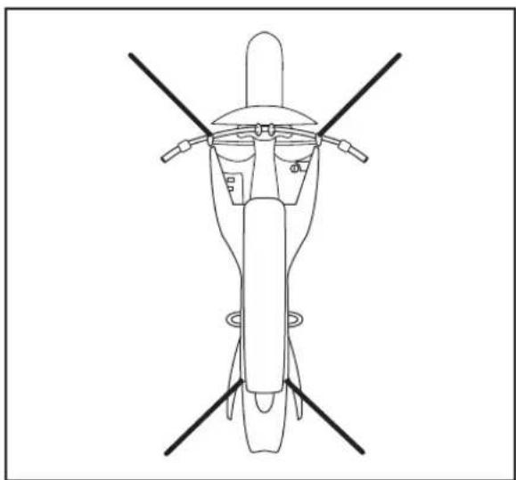
natural_image
Top-down line drawing of a helicopter viewed from above, showing front, top, and side views (no text or symbols)NOTES
Safety Information
General Safety Precautions
- This is a performance motorcycle and should be treated with extreme caution.
- Proper safety gear including a DOT approved helmet, riding boots, gloves, and protective clothing should be worn while riding to reduce the risk of potential injury. We highly recommend the use of full height riding boots since the vast majority of motorcycle injuries are leg and foot injuries. It is not recommended to ride without the correct protective clothing; this applies to even short journeys, and to every season of the year.
- Read all additional warnings and product instructions in this owner's manual, as well as safety labels, before operating your electric motorcycle.
-
Never carry a passenger. This motorcycle is designed for a SINGLE RIDER ONLY.
-
Never permit a guest to ride your electric motorcycle without proper instruction. These are performance motorcycles and should be treated with extreme caution.
- Never use alcohol or mind-altering drugs before operating your electric motorcycle.
- Persons unwilling or unable to take responsibility for their actions should not use this motorcycle. You assume all responsibility while operating your motorcycle. The seller will assume no liability for misuse or operator negligence.
- Prior to each use the rider must check everything in the "every ride" column of the maintenance schedules on pages 5-13 through 5-15, and the power pack function level as indicated on the instrument panel energy gauge.
-
Your safety depends in part on the good mechanical condition of the motorcycle. Be sure to follow the maintenance schedule and adjustment requirements contained in this manual. Be sure you understand the importance of checking all items thoroughly before riding.
-
Modifications of the motorcycle may render the vehicle unsafe and may cause severe personal injury. Zero Motorcycles cannot be held liable for non-approved modifications.
- Be very careful when loading or adding accessories to your motorcycle. Large, bulky, or heavy items may adversely affect the handling and performance of your motorcycle.
Important Operating Information
- Always turn the key switch and kill switch to the OFF position when not actively riding. It is very easy to forget that the motorcycle is powered up because it is silent. An accident can occur if the motorcycle is left powered up while getting on or off the motorcycle.
- Switch the power OFF when backing up or pushing the motorcycle while dismounted. It is possible to unintentionally twist the throttle, resulting in unexpected acceleration.
-
Use the rear brake when you are stopped on an incline. Do not hold the motorcycle using partial throttle or damage to the motor may occur.
-
The Zero X/MX power pack should be plugged in when storing the motorcycle for extended periods of time.
-
Keep your Zero X/MX connected to the charger when your motorcycle is sitting in storage or if it will be sitting unused for more than 7 days.
The power pack must be charged within 24 hours if fully discharged, and must be charged within 60 days if stored fully charged. Zero recommends you plug in your power pack after 7 days even if its fully charged. Please leave your power pack plugged in whenever possible.
WARNING: Charge the Zero power pack with the Zero charger.
-
Always firmly apply the rear brake while turning the key switch ON or OFF. In the event of a malfunction, the firm application of the rear brake will help keep the motorcycle from running away.
-
The power pack does not require or tolerate deep discharging. To get the most power pack life, recharge each power pack immediately after each ride. Leaving a power pack in a discharged state will cause damage. See Charging The Power Pack on page 4-12.
-
Failure to follow battery storage and charging instructions as described in this Zero Motorcycles Owner's Manual may void the warranty of your Zero motorcycle. These guidelines have been rigorously tested to ensure maximum battery efficiency and service.
Location Of Important Labels
The Vehicle Certification Label contains the following information:
• Gross Vehicle Weight Rating (GVWR)
• Gross Axle Weight Rating (GAWR) Front and Rear
• Production Identification Number (PIN)
• Rim Size
•Tire Pressures
• Manufactured Date

Power Pack Information Label
WARNING
IMPORTANT POWER PACK INFORMATION
- Before operating the motorcycle you must fully charge the power pack
- YOU MUST NEVER LEAVE THE POWER PACK UNPLUGGED/OFF THE CHARGER, FOR MORE THAN 7 DAYS
- Leaving the power pack unplugged for more than 7 days can cause irreparable harm to the power pack and may void your warranty.
• Always leave the power pack plugged in when not in use - The power pack can remain plugged in for an indefinite amount of time
• Over long durations the charger will monitor and maintain proper voltages within the power pack.
Please read the owner's manual for more information prior to operating the motorcycle.
Part No. 09-10-0013091 Rev. USA

MOTORCYCLES
WARNING
Throttle And Speed Control Label

IMPORTANT
THROTTLE AND SPEED CONTROL
The fully electric drivetrain of this motorcycle is different than any gas counterpart:
- There is no engine braking and no engine noise
- When going into corners or coming to a stop you will be fully dependent on your brakes
- It is easy to find yourself speeding due to the absence of engine noise
- Passersby will not hear your approach - be extra cautious when making turns, entering intersections or when people are likely to cross your path
Be aware that your motorcycle is still ON during stops and while at an "idle". Accidentally twisting the throttle can cause serious harm.
Please read the user manual for more information prior to operating the motorcycle.
IMPORTANT
NOTES
Controls And Components
Motorcycle Controls

Right Side View

Instrument Panel

A. Speed Control Switch
B. Main Power Indicator
C. Energy Gauge
D. Torque Control Switch
Speed Control Switch
The speed control is a two position switch that toggles between 0-40 km/h (0-25 mph) and 0-80 km/h (0-50 mph). To select either of the switch positions, the motorcycle must be stopped and the key switch in the OFF position.
The 0-25 position reduces the top speed of the motorcycle to below 25 mph. Using this setting typically results in greater range because the motorcycle is moving at a lower average speed. Due to the Zero motorcycle's unique power delivery, we recommend using the 0-25 mph speed selection for the first battery cycle to allow the new Zero rider to familiarize themselves with the electric power delivery.
The 0-50 position enables the motorcycle to achieve its top speed. Traveling at high speeds reduces overall range. Zero Motorcycles speed claims are based upon Zero Motorcycles test riders and an overall average of our high speed testing. These may vary from your results.
Main Power Indicator
The green LED is solidly lit when the motorcycle is ready to ride. When the green power LED is on, do not twist the throttle unless you are ready to ride. In the unlikely event you exceed the motorcycle's performance capabilities, the indicator will flash and gently oscillate the motor output to notify the rider. Back off of the throttle to reduce heat and eliminate the oscillation. Doing so will also eliminate the indicator flashing. If the green LED is flashing, the system has detected a fault. For troubleshooting, see pages 6-9 and 6-10.
Energy Gauge
The energy gauge on the motorcycle is used to inform you of the amount of remaining energy in the power pack. This gauge is to be read with the motorcycle stopped. When accelerating under full throttle, the energy gauge may dip down to red. The energy gauge is segmented into 3 colors, the colors indicate the following:
•Green indicates a full power pack.
- Amber indicates that the state of charge of the power pack is getting low.
- Red indicates that the state of charge of the power pack is very low and that the power pack should be recharged as soon as possible. The motorcycle will cease to operate soon due to a critically low charge level.
Torque Control Switch
The torque control is a two position switch that toggles between high and low. To select either of the switch positions the motorcycle must be stopped and the key switch in the OFF position.
The high torque position causes the motorcycle to accelerate at a significantly faster rate. This position is recommended for advanced riders.
Those who take advantage of the high torque are likely to see a slightly reduced range.
The low torque setting reduces the acceleration of the motorcycle to be less aggressive. It is an ideal setting to use for times when you want softer acceleration. This setting is also good for newer riders and for extending range.
Handlebar Controls
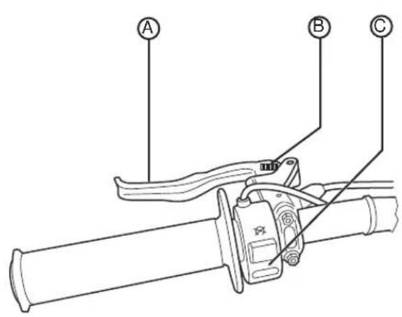
A. Brake Lever/Master Cylinder
B. Brake Lever Reach Adjustment
C. Kill Switch
D. Throttle

Left Handlebar Control
Kill Switch
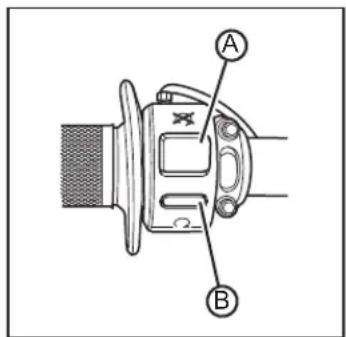
When the button (A) is pressed, it will kill power to the motor controller. The motor controller will remain in this state until the ON (B) button is pressed. The switch does not turn off all electrical circuits, just the operation of the motor.
Rear Brake Lever
The rear brake lever engages the rear brake when the lever is squeezed. When braking, the throttle should be in neutral/returned position. The brake lever is adjustable. To adjust, see Brake Adjustment on page 4-16.
Right Handlebar Control
Throttle Control
Twist the throttle in a counter-clockwise rotation (A) to accelerate the motor and start the motorcycle in a forward direction. Release the throttle and it will return to the neutral position (B), decelerating the motor.

Front Brake Lever
The front brake lever engages the front brake when the lever is squeezed. When braking, the throttle should be in the neutral/returned position. The brake lever is adjustable. To adjust, see Brake Adjustment on page 4-16.
NOTES
NOTES
Starting And Operating
First Time Set-Up
If your motorcycle was direct shipped you will need to perform the following:
- Remove the motorcycle from its shipping crate. See Uncrating Your Motorcycle on page 4-2.
- You must charge the power pack before riding the motorcycle. See Charging The Power Pack on page 4-12.
- Install the power pack. See Power Pack Swapping on page 4-6.
- Identify and inspect the wheels and brakes for leaks or irregularities.
-
Check the tire pressure and adjust to proper specifications. See Tire Inflation on page 5-8.
-
Inspect the hydraulic brake system. Follow the hydraulic lines from the reservoirs to the calipers and verify that there are no leaks or damage to the brake lines. Verify that the brakes function properly.
- Make sure the motorcycle key switch is OFF, then twist the throttle to make sure it's rotation is smooth and returns correctly.
- Inspect bolts and make sure they are tight. See Bolt Torque Table on page 5-2. Double check the fork, wheel, and brake bolts.
- Insert the key in the key switch, engage the rear brake and turn the key to the "ON" position. The energy gauge should read fully charged.
Uncrating Your Motorcycle
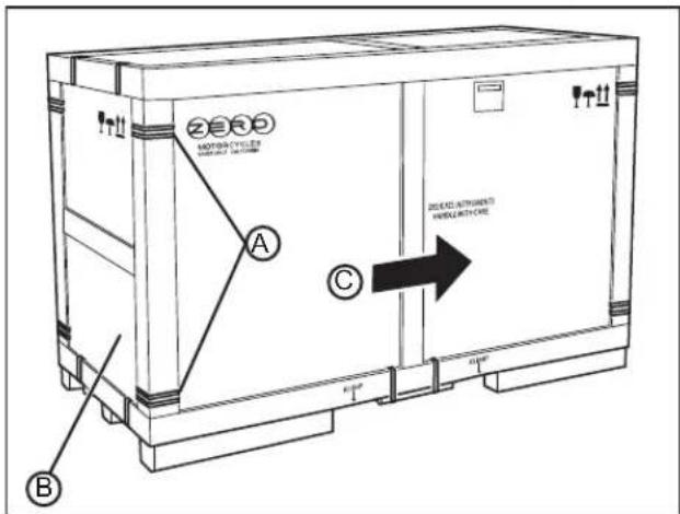
The X/MX motorcycle arrives almost entirely assembled. It is recommended that you have an assistant to help with the uncrating procedure. We advise wearing protective gloves and protective eyewear when uncrating the Zero motorcycle. It is possible during shipping that sharp edges or points may occur. Please use caution. Retain the crate and all other shipping items for future shipping of the motorcycle.
Note: The shipping crate may differ slightly than shown, below are general guidelines for uncrating the motorcycle.
- Remove the crate clamps (A) and remove the crate end panel (B).
- With the aid of an assistant, lift and move (C) the crate off of the base.
- With the assistant holding the motorcycle upright, remove the ratchet straps (B).
- Fold down the ramp (A) and lower the protective plastic.

- Remove the fork support (A), located between the wheel and front fender.

- Carefully roll the motorcycle off of the crate base.
General Operation
Pre-Ride Inspection
Before operating the Zero X/MX motorcycle, check the following to make sure the motorcycle is secure and intact:
•Power Pack
Make sure the onboard energy gauge is green, indicating a charged power pack. If the energy gauge reads below 3 bars (1/2) amber or red, we suggest you recharge before use.
- Drive Chain
Check chain slack and condition. Adjust and lubricate if necessary. The drive chain must be cleaned and lubricated at the intervals specified in the maintenance schedule. Otherwise, it will quickly wear out, especially when riding in dusty or wet areas. See Chain on page 5-8.
• Brakes
Squeeze each brake lever individually and push the motorcycle to see if it rolls. You should be able to lock-up the wheels completely by applying the brakes.
• Throttle
With the key switch in the OFF position, twist the throttle and release to verify that the throttle is smooth and returns correctly.
• Tires
Check both tires for condition and tread depth. Check cold tire pressure frequently. Check for damage and alignment. Maintain correct tire pressure as specified on page 5-8. Replace the tires when the tread height is 2 mm (0.08 in) or less.
CAUTION: Under-inflation is the most common cause of tire failure and may result in severe tire cracking, tread separation, "blowout," or unexpected loss of motorcycle control causing personal injury and possible death.
Key Switch Positions
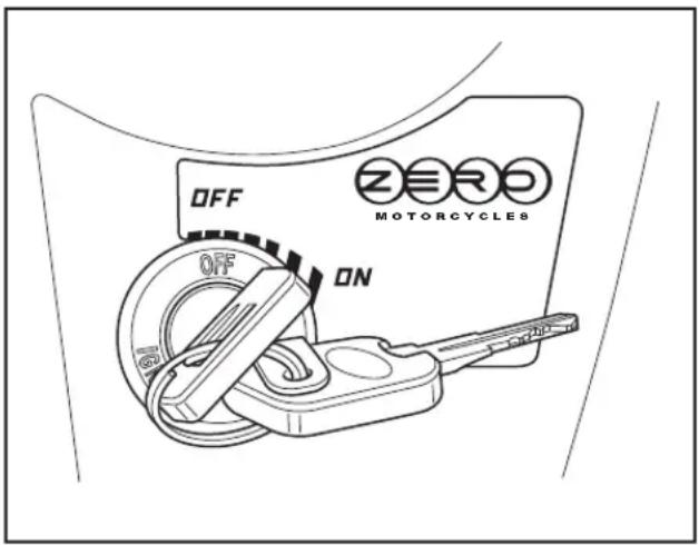
This is a two-position switch that is located on the top/front of the motorcycle, below the handlebar. The switch positions are as follows:
• OFF
•ON
The key should be removed from the motorcycle when parked, to prevent theft.
Power Pack
The battery is located within the power pack and requires no special break in period. Under normal use and correct power pack maintenance, the power pack should maintain most of its capacity for approximately 5 years, dependent on use. The charging time is the same if connected to 110 V AC or 220 V AC; this is an input to the charger. The charger output will be the same. The normal recharging time of the power pack is usually less than 2 hours in ambient temperatures. Out of the normal temperature range charging and run-time times will vary. The batteries should not be used outside of the range of -7°C - 71°C (20°F - 160°F); the Battery Management System (BMS) will turn off the motor controller outside of this range. It is recommend that you leave the motorcycle on the charger if you expect it to sit in storage or unused for over 7 days. The power pack must be charged within 24 hours if fully discharged, and charged within 60 days if stored fully charged. Zero recommends you plug in your Zero motorcycle after 7 days, even if fully charged. Please leave your Zero motorcycle plugged in whenever possible.
WARNING: Opening of the power pack is for trained Zero Motorcycles technicians. Please be aware that incorrect handling of a Zero battery can be dangerous. DO NOT OPEN!
The 6-digit serial number for the battery is located on a label on top of the power pack.
Add On Electrical Equipment
WARNING: Do not add anything electrical to your motorcycle unless approved by your CSC. Some electrical components can damage your motorcycle. Some add on electrical equipment can keep other components from working as they should or can dramatically reduce the range and or life expectancy of the power pack.
Power Pack Swapping
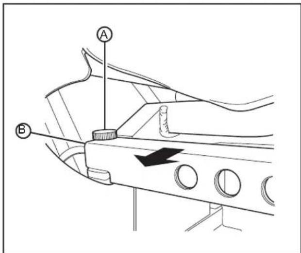
The X and MX motorcycles feature a quick change power pack. This allows the rider to charge one power pack while using another. To change the power pack, perform the following:
Removal
- Remove the key from the key switch and safely support the motorcycle.
-
Locate the knob (A) on the rear of the upper frame rail and remove.
-
Pull the frame rail (B) away from the motorcycle, unhooking it at the front.
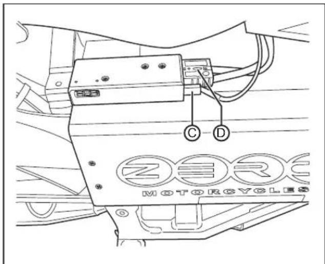
- Disconnect the power pack connectors (D) and (C).
Note: The power pack weighs 20.9 kg (46 pounds).
- Using a firm grip, slide the power pack out of the frame.
Installation
- Slide the power pack into the frame.
- Connect the power pack connectors.
- Install the frame rail into the front slot first, then push the rear side into the frame.
- Install and securely tighten the knob.
Battery Management System (BMS)
Every power pack contains a Battery Management System (BMS) which monitors the condition of the cells and optimizes the charging process to provide the highest-performance, longest-range, and longest-life for the power pack.
The BMS also monitors the battery for a host of predefined conditions, and then takes actions according to these conditions. Some of these conditions are listed below. Also see Understanding Beep Sequences on page 6-3.
•Low Voltage
Action: When a low voltage is detected the beeper is sounded to alert the rider that they should stop riding the motorcycle. This beeper beeps approximately once every 10-12 seconds when the motorcycle is being ridden and then once every minute when the motorcycle is inactive.
•Dangerously Low Voltage
Action: If the voltage drops to the point that may damage the battery cells, the power pack sends a signal to disable the motor controller and the motorcycle will not run until the voltage returns to an acceptable level.
•High Or Low Temperature
Action: If the BMS senses that the power pack is too hot, above 71^ C ( 160^ F), or too cold, below -7^ C ( 20^ F), it sends a signal to disable the motor controller and the motorcycle will not run until the temperature returns to an acceptable level. The charger will also be disabled in this condition.
•High Voltage
Action: If the BMS detects a voltage that is too high, it shuts down the charger to prevent over-charging.
The BMS is sealed inside the power pack. As a rider, you don't need to think much about the BMS - it just silently does its job as you charge, ride, and store your motorcycle. There are only two things you might need to know about your Z-Force BMS:
- Beep-Signals
The BMS will emit an “OK” beep-tone every time you turn-on your motorcycle. The BMS might also respond to other internal conditions and errors with different kinds of beeps. This section explains the different beep-patterns and their meanings.
•Safety Interlocks
The BMS can disable the motorcycle's throttle-control if the power pack is fully discharged, or in case of other errors. The BMS can also disable charging under certain circumstances. The information below explains the different conditions which can cause the BMS to disable the throttle-control or the battery-charger.
Beeps
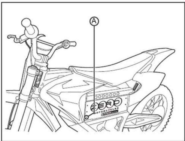
The BMS includes an electronic beeper sealed inside the power pack. The beeper is located on the left front of the power pack behind the opening (A). Do not cover this opening, it is intentionally left open.
The BMS will beep only under two circumstances:
- When the motorcycle key switch is turned from "OFF" to "ON." When the motorcycle is turned ON, the BMS will perform a self-test. It will always sound a beep-signal when the test finishes. The beep-pattern reports the self-test result.
- Whenever the key switch is "ON," and the power pack is nearly empty. The BMS will continuously sound a warning when the power pack is low. The warning will stop when the motorcycle is turned-off.
Battery Charger
Keep your power pack connected to the charger when your motorcycle is sitting in storage or if it will be sitting unused for more than 7 days. The power pack must be charged within 24 hours if fully discharged, and charged within 60 days if stored fully charged. Zero recommends you plug in your Zero motorcycle after 7 days, even if fully charged. Please leave your Zero motorcycle plugged in whenever possible.
WARNING: Charge the Zero power pack with the Zero charger.
When charging the motorcycle's power pack the charger can be left on, even after the power pack is fully charged. There are two possible cases that can occur:
- When left on the charger, the power pack will receive a full charge. Once fully charged, the charger will check the status of the power pack once every 72 hours to ensure that it maintains a full charge. When fully charged a green light will illuminate on the charger. Should the charger not read that the power pack is full, it will continue to attempt to fully charge the power pack. In this event the green light may not illuminate, however, the power pack may be fully charged. To ensure that the power pack is charged, check the energy gauge prior to riding.
- If the power pack terminates the charge before the charger reaches the state previously mentioned, then the charger will continue to cycle and will top off the power pack until the power pack is removed, or the charger reaches the complete state previously noted.

A. AC Power Cord
B. AC Power Cord Connection
C. Battery Charger
D. Charger LED Indicators
E. Power Pack Charging Connector
Charger LED Indicators
Note: The charger must be plugged in for the charger's indicators to illuminate. See Battery Charger on page 4-10 for location.

Power Pack LED Indicator Diagram
| Ammeter(Amber) | 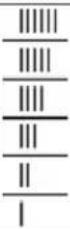 | Solid: Displays approximate scale of current output during bulk phase. High internal charge temperature. Current output reduced. | |
| Flashing: | Also displays algorithm #1-6 for 11 seconds if no power pack is connected. | ||
| 80% Charge(Amber) | [DS4] | Solid: Bulk charge phase complete, 80% charged. In Absorption phase. | |
| Flashing: | With no power pack connected, indicates algorithm # selected by number of flashes. | ||
| 100% Charge(Green) |  | Solid: Charging complete. Charger in Maintenance Mode. | |
| Flashing: | Absorption phase complete. In Finish phase. | ||
| AC On(Amber) | [8STX] | Solid: AC | Power good. |
| Flashing: | Low AC Voltage, check voltage and extension cord length 7.6m (25 FT) 12 AWG | ||
| Fault(Red) | [134C] | Flashing: | Charger error. Reset charger power and see Troubleshooting Section 6. |
Charging The Power Pack
WARNING: Charge the Zero power pack with the Zero charger. It is possible for lithium ion cells to overheat and burst. It is recommended to charge in a location that is away from combustible materials and in a well ventilated area. Avoid outdoor charging of your power pack in the rain.
(Installed in Motorcycle)
- Ensure that the key switch is in the "OFF" position.
- When the motorcycle's energy gauge is on the second or third bar when not under load, the power pack needs to be charged. Frequent top off charging is good for the power pack's life span, so do not hesitate to charge frequently.
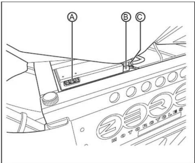
- Disconnect the main power cable connector (C) and throttle enable cable connector (B).
- Connect the battery charger to the power pack connector (A).
-
Always connect the charger to a GROUNDED outlet. When using an extension cord, avoid excessive voltage drops by using a grounded, 3-wire, 12-AWG cord no longer than 7.6 m (25 ft). The charger can be used on 110 V AC or 220 V AC current. The voltage does not change the amount of time that the motorcycle takes to charge.
-
AVOID connecting the Zero charger and another device to a single 15A/20A or the circuit may become overloaded.
-
Charging a fully discharged power pack takes about 2 hours.
-
Your power pack is equipped with an "Emergency Energy Reserve Beep." When your power pack makes an audible beep, it has only a few miles of range left. This beep tells you your power pack is dangerously low on energy and needs to be recharged immediately. Your power pack will continue to beep even when it's charging until it has recovered its "Emergency Energy Reserve."
-
When the power pack is fully charged, disconnect the charger and reconnect the power pack to the motorcycle.
(Not Installed in Motorcycle)
-
Remove the power pack from the motorcycle. See Power Pack Swapping on page 4-6.
-
Connect the charger to the power pack.

natural_image
Line drawing of an electronic device with a rectangular box connected to a cable, showing wiring and components (no text or symbols)-
Always connect the charger to a GROUNDED outlet. When using an extension cord, avoid excessive voltage drops by using a grounded, 3-wire, 12-AWG cord no longer than 7.6 m (25 ft). The charger can be used on 110 V AC or 220 V AC current. The voltage does not change the amount of time that the motorcycle takes to charge.
-
AVOID connecting the Zero charger and another device to a single 15A/20A circuit or the circuit may become overloaded.
-
Charging a fully discharged Zero X/MX power pack takes about 2 hours.
-
Your power pack is equipped with an "Emergency Energy Reserve Beep." When your power pack makes an audible beep, it has only a few miles of range left. This beep tells you your power pack is dangerously low on energy and needs to be recharged immediately. Your power pack will continue to beep even when it's charging until it has recovered its "Emergency Energy Reserve."
-
When the power pack is fully charged, disconnect the charger.
-
Install the power pack into the motorcycle. See Power Pack Swapping on page 4-6.
Operating Your Motorcycle
Starting
- Turn the key switch to the ON position.
- Verify that the energy gauge reads fully charged.
- With the brake applied, press the kill switch to the ON position.
- Release the brake and twist the throttle toward you (counter-clockwise) to increase speed. When the throttle is twisted away from you (clockwise), the speed will decrease.
Braking
- On the right handlebar is a hand operated brake lever. This brake lever controls the front brake when the lever is squeezed.
- On the left handlebar is a hand operated brake lever. This lever controls the rear brake. When braking, the throttle should be in the neutral/returned position.
The front and rear brake should be applied together, with a slight amount more of braking on the front.
CAUTION: If you apply the front or rear brake hard enough, it is possible to lock the wheels. This could cause you to lose control of the motorcycle. We suggest progressive use of the brakes to bring the Zero motorcycle to a complete stop without locking the wheels. Your Zero motorcycle is a light weight performance product and therefore practice is recommended to safely perfect emergency stops.
Stopping
- With the throttle in the neutral position and the brake applied, press the kill switch to the OFF position. This switch can also be used in an emergency to shut the motor off.
- Turn the key switch to the OFF position and remove the key. To prevent theft, the key should be removed anytime the motorcycle is left unattended.
- Be sure to charge the power pack after each ride. See Charging The Power Pack on page 4-12.
Brake Adjustment
Master Cylinder/Lever Angle
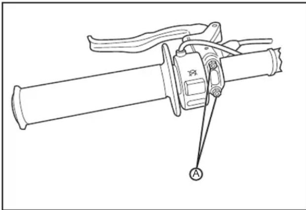
- Loosen, but do not remove, the handlebar clamp screws (A).
- Position the master cylinder/lever on the handlebar in your desired position.
- Tighten the handlebar clamp screws so there is an equal gap between the master cylinder and clamp at both clamp screws. See Bolt Torque Table on page 5-2.
natural_image
Technical line drawing of a mechanical clamp or lever assembly with labeled component A (no text or symbols beyond label)Lever Reach

Adjust the brake lever reach by turning the reach adjustment knob (A). Turning the knob counter-clockwise will adjust the lever closer to the handlebar. Turning the knob clockwise will adjust the lever further from
the handlebar. Do not attempt to force the adjustment knob beyond its limits.
Suspension Adjustment
Front Fork Adjustment
A shock has two main actions: compression when the shock gets compressed, and rebound when the shock returns back to full length. Compression damping is the adjustment that determines how fast or slow the fork compresses. Rebound damping is the adjustment that determines how fast or slow the fork rebounds.
MX Sport and Extreme Models:
-
Bleed Screw - The small Allen screw (A) at the top of the fork leg is the "bleed" screw. The bleed screw serves two purposes:
-
Transporting your motorcycle. See Transporting on page 1-10.
-
Bleeding the fork: Bleed the fork regularly, let any excess air out after each ride.
-
Rebound Damping - The rebound damping is adjusted by turning the slotted brass adjuster screw (B) on the top of both fork legs. Next to it will be the writing S-F, meaning Slow and Fast. The adjuster has 18 stages of adjustment. This determines how quickly the fork returns to its extended position after being compressed. Turning the rebound adjuster screw clockwise will slow the rebound speed down making it better for larger, rolling terrain or bumps. Turning the rebound adjuster screw counter-clockwise will increase the reboundspeed making it better for smaller, rougher bumps. Adjust each fork leg evenly.

- Compression Damping - The compression damping is adjusted by turning a screw on the bottom of each fork leg. There is a rubber dust cover protecting the screw and a jam nut (C) securing the screw (D). The adjuster has 12 stages of adjustment. Turn the adjuster clockwise for slower compression. To speed up compression, turn the adjuster counter-clockwise. Start with a middle setting and fine tune the compression from there. Proper compression will allow the tire to track the ground over consecutive bumps. Compression that is set too slow will pack-up (feel harsh over consecutive bumps) while compression that is set too fast will cause the fork to bottom out harshly. If the fork is bottoming out, turn the adjuster one click at a time until the bottoming-out stops. Adjust each fork leg evenly. Replace the rubber dust cover after the adjustment.

X Sport and Extreme Models:
- Spring Tuning - Spring tuning is accomplished by changing the air pressure within the fork. To determine if the air pressure is correct, measure the fork travel. This is done by:
- Put a zip tie around the stanchion tube and slide it up to the bottom of the wiper seal.
- Ride the motorcycle under a variety of conditions you normally experience, including some conditions that you feel should use the full fork travel.
• After the ride, inspect the position of the zip tie. Note the position from the fork wiper seal to the axle clamp. If the zip tie is close to the bottom you may want to stiffen up the fork or if the zip tie moved very little you may want to soften the fork. This is referred to as Pre-load.
-
Pre-load - Adding or removing air from the fork leg changes pre-load. This is done by unscrewing the dust cap from the top of the left fork leg. Under the cap is a Schrader valve (A); this is where you would add or remove the air (see image on page 4-20). More air pressure will have less sag and a firmer feel. Less air pressure will have more sag and a softer feel. The fork is designed to use zero pressure and should never exceed 275 kpa (40 psi). The fork holds a small amount of air; avoid large volume air compressors as this will damage the fork.
-
Damping Tuning
- Rebound Damping - Rebound damping is adjusted by turning the slotted brass adjuster screw (B) on the right fork leg (see image on page 4-20). The adjuster has 4 turns of adjustment. Turn the adjuster clockwise for slower rebound. To speed up rebound, turn the adjuster counter-clockwise. Start with a middle setting and fine tune the rebound from there. Proper rebound damping will allow the tire to track the ground over consecutive bumps. Rebound that is set too slow will pack-up (feel harsh over consecutive bumps) while rebound-
set too fast will cause the fork to top out harshly. If the fork is topping out and you have the correct spring for your weight, turn the adjuster one turn at a time until the top-out stops.
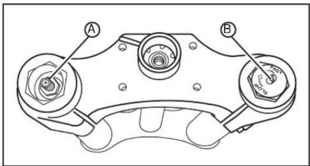
•Compression Damping - Compression damping can be changed in two ways:
-
By adjusting the compression damping adjuster screw (B) on the back of the canister on the bottom of the right fork leg. The adjuster has 4 turns of adjustment. Turning it clockwise slows compression and turning it counterclockwise speeds up compression.
-
By adding or removing air pressure (or nitrogen) from the Schrader valve (A) on the bottom of the right fork leg. Unscrew the dust cap and adjust between 345 kpa (50 psi) minimum and 1,207 kpa (175 psi) maximum.

CAUTION: Exceeding the maximum recommended damping pressure can result in catastrophic rupture of the reservoir canister, causing serious injury or death.
Adding air will increase the compression damping (slow it down) and removing air will decrease compressing damping (faster compression). Less compression damping will increase fork dive but will feel smoother over small bumps.
More compression damping will feel stiff over small bumps but will be more resistant to bottoming out. Never run less than 345 kpa (50 psi) in the canister.
Rear Shock Adjustment
Spring Adjustment:
Obtaining the correct rear spring rate is critical for proper handling. The spring rate must be set to match the weight of the rider. Heavier riders require stiffer spring rates. A good approximation of your rear spring requirements can be found by measuring the rear suspension's sag. This measurement will quickly determine if your rear spring is approximately correct for your weight. This adjustment is a recommendation guideline; personal riding preference may vary from the specifications given.
- Checking Sag
-
Support your motorcycle on a stand with the rear wheel off the ground.
-
Measure vertically from the rear axle to the rear fender; mark this spot as it will be used for other measurements.
-
Record this measurement, this will be measurement M1.

-
Remove the motorcycle from the stand.
-
Wearing your normal riding apparel, sit on the motorcycle.
-
Have an assistant hold the motorcycle up, your feet should be on both pegs.
-
Bounce the suspension a couple of times.
-
Have a second assistant take a measurement using the same locations as in step 2.
-
Record this measurement, this will be measurement M2.

- Subtract the second measurement (M2) from the first measurement (M1).
Example:
| M1 600 mm | (24 in) | |
| M2 - 500 mm | (28 in) | |
| Sag = 100 mm | (4 in) |
If the total is between 90 to 100 mm (3.5 to 4.0 in) the sag is correct. If it is not within 90 to 100 mm (3.5 to 4.0 in) the spring pre-load should be adjusted. See Spring Pre-load Adjustment.
•Spring Pre-load Adjustment
-
Clean any dirt or debris from the threads of the shock.
-
Using a spanner wrench loosen the lock nut (A).
-
For measurements less than 90 mm (3.5 in), decrease the pre-load on the spring by turning the spring nut (B) counter-clockwise on the shock. If more than 100 mm (4.0 in), increase the pre-load on the spring by turning the spring nut (B) clockwise on the shock.
-
Recheck the sag. If the sag is correct, tighten the lock nut (A).
- Rebound Adjustment - The rebound adjuster knob (C) is at the bottom of the shock. It has 8 stages of adjustment. Printed on the knob is S-F, meaning Slow and Fast. The rebound adjuster knob controls how slow or fast the shock returns to its extended position after being compressed. Turning the knob clockwise, or S direction, is good for big impacts. Turning the knob counterclockwise, or F direction, is good for many smaller and more frequent impacts.

NOTES
Maintaining Your Motorcycle
Owner's Responsibilities
- This owner's manual should be considered a permanent part of this motorcycle and should remain with it even if the motorcycle is subsequently sold.
- Perform routine care and maintenance on your electric motorcycle as detailed in this owner's manual.
-
Use only genuine Zero approved parts and accessories.
-
The operator is responsible for learning and obeying all country, federal, state, and local laws governing the operations of an electric motorcycle.
- Always wear a DOT approved helmet, goggles, appropriate boots, and all other appropriate safety equipment when operating an electric motorcycle.
Bolt Torque Table
| LOCATION | ITEM TORQUE NOTES | ||
| A | Front axle pinch bolts 11-13 N | •m (8-10 lb ft) | Use LOCTITE® 242®* |
| Front axle end bolts 18-20 N | •m (13-15 lb ft) | ||
| B Front | caliper mount bolts 11-13 N | •m (8-10 lb ft) Use LOCTITE | ® 242®* |
| C Triple | tree pinch bolts 13-15 N | •m (10-11 lb ft) | Use LOCTITE® 242®* |
| D | Main pivot bolt/nut (swingarm) | 105-110 Nm (77-81 lb ft) | Use LOCTITE® 270TM* |
| E Shock | mount bolts 13-15 N | •m (10-11 lb ft) | Use anti-sieze lubricant |
| F Rear | caliper mount bolts 11-13 N | •m (8-10 lb ft) Use LOCTITE | ® 242®* |
| G | Rear axle pinch bolts | 11-13 Nm (8-10 lb ft) Use LOCTITE | ® 242®* |
| H | Rear axle end bolts | 18-20 Nm (13-15 lb ft) | Use LOCTITE® 242®* |
| I | Motor mount bolts | 30-32 Nm (22-24 lb ft) | Use anti-sieze lubricant |
| J Master | cylinder/lever clamp screws 3-4 N | •m (27-35 lb in) | Use LOCTITE® 242®* |
| K Hand | ebar clamp mount bolts 18-20 N | •m (13-15 lb ft) | Use LOCTITE® 242®* |
* or equivalent
See Bolt Torque Table on page 5-2.

See Bolt Torque Table on page 5-2.

See Bolt Torque Table on page 5-2. Zero recommends you plug in your Zero motorcycle

Power Pack
WARNING: You must leave your motorcycle on the charger if you expect it to sit in storage or unused for over 7 days.
The power pack must be charged within 24 hours if fully discharged, and charged within 60 days if stored fully charged.
after 7 days, even if fully charged. Please leave your Zero motorcycle plugged in whenever possible.
- The power pack is a lithium ion power system. While it does require charging, it does not require maintenance.
- The power pack should be kept away from excessive heat. The lithium ion cells should not get above 71°C (160°F). Do not store in a hot car or trailer or leave the power pack in direct sunlight.
- Only an authorized service agent is qualified to have access to and troubleshoot the power pack.
- Dispose of the power pack according to your state and local laws. It is encouraged that the power pack be recycled rather than disposed of in landfills. Locate a recycling center in your area; if one cannot be found, contact Zero at support@zeromotorcycles.com.
General Maintenance
Motor
CAUTION: Wear safety glasses when using compressed air to avoid eye injuries.
The motor does not require much maintenance, but dust can collect inside the motor and can cause premature brush wear. If you ride in dusty conditions it is important to blow the dust out of the motor with compressed air. Do this only in a well ventilated area.
Brakes
Brake Fluid
The brakes are a sealed system and should require no additional brake fluid unless a leak is detected.
Brake Pad Inspection
The brake pads must be inspected when specified in the maintenance schedule. See Maintenance Schedule on pages 5-13 through 5-15. Visually inspect the brakes by looking at the remaining brake pad material through the inspection port in the brake caliper.
If the brake pads (A) are worn, replace both brake pad immediately.

natural_image
Technical line drawing of a mechanical assembly with no visible text or symbolsSuspension
Front
For maintenance, see Maintenance Schedule on pages 5-13 through 5-15.
To adjust the fork, see Suspension Adjustment on page 4-16.
Rear
CAUTION: The shock absorber assembly contains highly pressurized gas.
- Do not attempt to tamper with or open the cylinder or shock.
- Do not subject the shock to high temperature or open flame.
Doing either of these can cause the cylinder or shock to explode causing personal injury or death.
For maintenance, see Maintenance Schedule on pages 5-13 through 5-15.
To adjust the shock, see Suspension Adjustment on page 4-16.
Wheels And Tires
Inspect both wheels for the following:
•Bent, loose, or missing spokes
•Bent or cracked wheels
- Impact marks on the wheels
Inspect both tires for the following:
• Cuts, cracks, splits, missing tread lugs, or bruises in the tread or sidewall area
• Bumps or bulges within the tire body
- Uneven tire tread wear. Wear on one side of the tire tread or flat spots in the tire tread indicate a problem with the tire or motorcycle.
• Exposed tire tread or cords
If either of the wheels or tires are found to have any of these conditions, replace the wheel and/or tire immediately.
Tire Inflation
CAUTION: Under-inflation is the most common cause of tire failure and may result in severe tire cracking, tread separation, "blowout," or unexpected loss of motorcycle control causing personal injury and possible death.
The tire inflation pressure should be checked and adjusted before each ride. The tire pressure is checked using an accurate gauge when the tires are cold. This means that the tires have not been ridden on for 3 hours. Always replace the valve stem cap when finished.
| MODEL FRONT REAR | ||
| X 103-241 | kpa(15-35 psi) | 103-138 kpa(15-20 psi) |
| MX 138-221 | kpa(20-32 psi) | 103-138 kpa(15-20 psi) |
Chain
Cleaning The Drive Chain
CAUTION:
- Wear safety glasses when cleaning the chain to prevent eye injuries.
- Never have the motor spinning the wheel. Turn the wheel only by hand. Failure to do so could result in serious personal injury.
- Never place your hand or any other body part between the chain and sprockets. Work with the chain only in the middle between the two sprockets. Failure to do so could result in serious personal injury.
- Do not allow any of the cleaner to get on the brake rotors or brake pads. If the rotors are contaminated with cleaner, it will impair the motorcycle's ability to stop. This could result in serious personal injury.
Follow the manufacturer's instructions for the chain cleaner you are using; see general guidelines on page 5-9.
- Remove the key from the key switch.
- Set the motorcycle on a stand or lift so the rear wheel is free to spin. While turning the wheel by HAND, spray the inside of your entire chain with a good coating of chain cleaner and let it sit for a few minutes.
- Using a brush, fill the bristles with spray from the chain cleaner. Begin gently scrubbing the chain on the top of your swingarm using the brush.
- Do this for the entire length of the chain. Now do the same thing for the inside/bottom of the chain.
- Using the brush, clean both sides of the rear sprocket. Let this soak for 5 minutes.
- Using a hose, rinse the entire chain and using a clean rag wipe any residual moisture from the chain.
Lubricating The Drive Chain
CAUTION:
- Wear safety glasses when lubricating the chain to prevent eye injuries.
- Never have the motor spinning the wheel. Turn the wheel only by hand. Failure to do so could result in serious personal injury.
- Never place your hand between the chain and sprockets. Work with the chain only in the middle between the two sprockets. Failure to do so could result in serious personal injury.
- Do not allow any of the lubricant to get on the brake rotors or brake pads. If the rotors are contaminated with lubricant, it will impair the motorcycle's ability to stop. This could result in serious personal injury.
Follow the manufacturer's instructions for the chain lubricant you are using; below are the general guidelines.
- Turn the wheel backwards slowly and spray the inside of the chain on the inside of the links.
- Turn the wheel backwards slowly and spray the outside of the chain on the outside of the links.
- Let the motorcycle stand for 30 minutes to allow the lubricant to penetrate the link rollers.
Checking The Drive Chain
- Remove the key from the key switch.
- Using a ruler, grasp the chain halfway between the front and rear sprockets.
- The chain should move 16 mm (.63 in) in either direction, so 32 mm (1.25 in) of total free play.
- If the chain's free play is not within specifications it will need to be adjusted. See the Drive Chain Adjustment Procedure.

Drive Chain Adjustment Procedure
- Remove the key from the key switch.
- Loosen both front motor mount Allen bolts (B).
- Loosen both rear motor mount Allen bolts (A).
- Loosen the 10 mm jam nut (C) on the chain tensioner.
- Turn the tensioner bolt (D) a 1/4 turn at a time until the chain free play is within specification.
- Tighten all motor mount Allen bolts. See Bolt Torque Table on page 5-2.
- Tighten the 10 mm jam nut on the chain tensioner. See Bolt Torque Table on page 5-2.
- Test ride the motorcycle.
- Recheck the chain for proper adjustment after the test ride and readjust if necessary.

Cleaning
To prolong the life of your motorcycle it should be washed periodically. Regular cleaning, using correct methods, is an important factor in maintaining the value of your Zero motorcycle. It also ensures that safety-relevant parts remain in full working order.
CAUTION: After cleaning and before starting on your journey, always test the brakes.
If tar, bugs, or other similar deposits have accumulated, wash them off as soon as possible. Do not use steam cleaners; they can cause water intrusion of bearing, seals and electrical components. When using pressure washers, avoid spraying water of great force around the instrument panel or controller. Avoid using strong acidic wheel cleaners, especially on spoked wheels. If such products are used on hard to remove dirt, do not leave the cleaner on the affected area any longer than instructed. Thoroughly rinse the area off with water, immediately dry it, and then apply a corrosion protection spray.
WARNING: Improper cleaning can damage electrical components, cowlings, panels and other plastic parts. Use only a soft, clean cloth or sponge with mild detergent and water to clean plastic.
Do not use any harsh chemical products on plastic parts. Be sure to avoid using cloths or sponges which have been in contact with strong abrasive cleaning products, solvent or thinner, fuel (gasoline), rust removers or inhibitors, brake fluid, antifreeze or electrolyte.
After gently washing the motorcycle be sure to allow all of the electrical components to dry prior to operation. If the motorcycle is ridden immediately after being washed, apply both brakes several times in order to remove any moisture from the brake linings. Do not use products such as tire dressings on tires as this will deteriorate traction.
Parking And Long Term Storage
-
It is required to always leave the power pack plugged in when the Zero X/MX is not in use. The Zero X/MX charger is designed to maintain a balanced and complete charge at all times without wasting any electricity.
-
Over extended periods of time the power pack is checked every 72 hours to ensure that the cells are balanced and that the power pack is full. Once the power pack is "topped off" the charger stops charging and continues to monitor the power pack. This ensures that electricity is not wasted in maintaining an optimized power pack.
-
To prolong the life of your power pack you should store your motorcycle in a cool area. Storing your motorcycle in a hot area will cause your power pack's life to be shortened.
-
If, for some reason, your motorcycle was not plugged in for several days you should always charge it up before operation.
For more information on the power pack and the electrical system see Battery Management System (BMS) on page 4-7.
WARNING: Opening of the power pack is for trained Zero Motorcycles technicians. Please be aware that incorrect handling of a Zero battery can be dangerous. DO NOT OPEN!
Maintenance Schedule
The scheduled maintenance must be performed in accordance with this chart to keep the Zero X/MX motorcycle in top running condition. The initial maintenance is vitally important and must not be neglected.
| NO. | ITEM ROUTINE | EVERY | RIDE | INITIAL TIME INTERVALS | |||||
| 1 month 6 | months 12 | months 18 months | 30 months | ||||||
| 1 | Front Brake | Check operation, and for fluid leakage.Replace brake pads if necessary. | √ | √ | √ | √ | √ | ||
| 2 | Rear Brake | Check operation, and for fluid leakage.Replace brake pads if necessary. | √ | √ | √ | √ | √ | ||
| 3 | Brake Hoses | Check for cracks or damage. Replace if necessary. | √ | √ | √ | √ | √ | √ | |
| 4 | Wheels | Check runout and for damage. Replace if necessary. | √ | √ | √ | √ | |||
| 5 | Tires | Check tread depth and for damage.Replace if necessary.Check air pressure. See page 5-8.Correct if necessary. | √ | √ | √ | √ | √ | √ | |
| 6 | Wheel Bearings | Check bearings for smooth operation.Replace if necessary. | √ | √ | √ | ||||
| 7 | Swingarm Pivot Bearings | Check bearing assemblies for looseness.Moderately repack with lithium grease.Ensure main pivot bolt is properly torqued.(See Bolt TorqueTable on page 5-2) | √ | ||||||
| 8 | D r i | Check chain slack/alignment and condition.Adjust and lubricate chain with chain lubricant thoroughly.Replace worn chain. | √ | Every month and after washing the motorcycle or riding in the rain | |||||
| 9 | Steering Bearings | Check bearing assembly for looseness.Moderately repack with lithium grease every 24 months. | √ | √ | √ | Repack | √ | ||
| 10 | Chassis Fasteners | Check all chassis fittings and fasteners.Correct if necessary. | √ | √ | √ | ||||
| NO. | ITEM ROUTINE EVERY | RIDE | INITIAL TIME INTERVALS | |||||
| 1 month 6 | months 12 | months 18 months | months 24 months | 30 months | ||||
| 11 | Front Fork | Check operation and for oil leakageService/Rebuild if necessary. Refer to the service manual for more information. | √ | √ | √ | √ | ||
| 12 | Rear Shock Absorber Assembly | Check operation and for oil leakageReplace if necessary. | √ | √ | √ | √ | ||
| 13 | Throttle Grip | Check operation and free play. | √ | √ | √ | √ | ||
Accessories
Zero accessories are designed to complement and function with other systems on your motorcycle. Your CSC can accessorize the motorcycle using genuine Zero accessories.
A full line of parts, accessories, and apparel can be found on the Zero Motorcycles website.
Fuses
Whenever there is an excessive amount of current flowing through a circuit, the fusible element will melt and create an open or incomplete circuit. Fuses are a onetime protection device and must be replaced each time the circuit is overloaded. Replace the fuse with one of equal current rating. If the fuse melts repeatedly, have the electrical system inspected by your CSC. There is one 4 amp ATM-4 fuse on the X/MX. The fuse controls the coil side of the motor controller solenoid and the key switch.
The inline fuse holder (A) is located in the front of the frame, between the instrument panel and the key switch.

natural_image
Technical line drawing of a mechanical assembly with labeled component A (no text or symbols beyond label)Follow the maintenance schedules on pages 5-13 through 5-15. After a scheduled service or routine is performed, record the information on the chart below.
| DATE ITEM | SERVICE/ROUTINE DESCRIPTION |
NOTES
Troubleshooting
All of the motorcycles are carefully inspected before they are delivered. Even after the motorcycles are inspected, some technical issues can occur. The following information offers a guide to help you to identify an issue, and if possible, repair it yourself. If you are unable to solve an issue with your Zero X/MX electric motorcycle, take it to an authorized Certified Service Center (CSC) at your convenience. If there is no CSC in your area call Zero Motorcycles customer service.
Power Pack And Charger
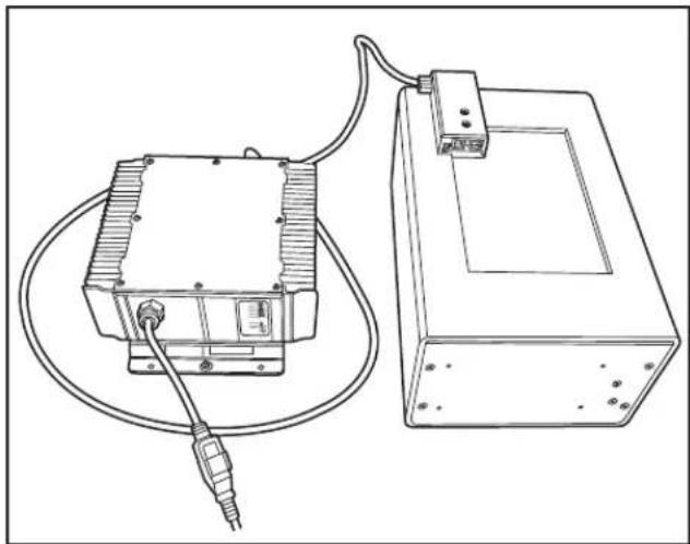
If a fault occurs during charging, count the number of times the red light flashes on the charger in between pauses. See page 4-11 for the location of the red light. Refer to the table on page 6-2 for the possible cause and solution to the issue.
natural_image
Technical line drawing of an electronic device with a cable and connector, no text or symbols present| NUMBER OF RED FLASHES | CAUSE SOLUTION | ||
| 1 | * | Power pack high voltage | Reset charger (interrupt AC power for 15 seconds). |
| 2 | ** | Power pack low voltage | Reset charger (interrupt AC power for 15 seconds). |
| 3 | *** | Charge timeout: caused by power pack not reaching required voltage. Charger output was reduced due to high temperatures. | Check connections. Operate charger at a lower ambient temperature. |
| 4 | **** | Check power pack: power pack could not be trickle charged up to minimum voltage. | Contact CSC. |
| 5 | ***** | Over-temperature: charger shut down due to high internal temperature. | Ensure sufficient cooling air flow and reset charger (interrupt AC power for 15 seconds). |
| 6 | ***** | Charger internal fault | Reset charger (interrupt AC power for 15 seconds). Contact CSC if fault persists. |
Understanding Beep Sequences
The Battery Management System (BMS) is located inside the power pack and is fitted with a beeper to provide audible notifications about the status of the power pack. Below you will find information on the meaning of the beep sequences.
| PATTERN WHEN MEANING SOLUTION | ||||
| 1 Short Key-on Self-Test Pass BMS OK. Ready to ride! | ||||
| 1 Trill2 Long |  | Key-on | Charger Still Plugged-In | Unplug charger & try again. |
| 2 Long Ke |  | Charge power pack before riding. | ||
| 4 Long Ke |  | |||
| 5 Long Ke |  | Power Pack Unbalanced | Leave on charger for 24 hours. | |
| 4 Short1 Long |  | Riding | Low-Power Pack Waming | Charge soon. |
Power Pack Empty
If the power pack is completely empty, an error-beep will sound and the BMS will disable the throttle. You cannot ride the motorcycle until you recharge the power pack. If the Power Pack Empty error-beep still sounds after two hours of charging time, contact your CSC. Your power pack may need to be repaired or replaced.
Too Hot
The power pack contains internal temperature sensors. If the BMS measures excessive internal temperatures, it will sound an error-beep and disable the throttle. You cannot ride the motorcycle until the power pack cools down. Place the motorcycle in a cool, well-ventilated location and wait a few minutes before riding again. If the Too Hot error-beep still sounds after the power pack has had time to cool down, contact your CSC. Your power pack may need to be repaired or replaced.
Power Pack Unbalanced
The power pack contains many individual cells. The BMS continuously monitors the cells and tries to keep them all “in balance” (at the same level-of-charge). If any of the cells are grossly out-of-balance, the BMS will sound a Power Pack Unbalanced error-beep and disable the throttle. You cannot ride the motorcycle until the problem is resolved.
The solution to the problem is to plug-in the charger and allow the power pack to charge for 72 hours. This will allow the BMS to re-balance the cells in the power pack. If the Power Pack Unbalanced error-beep still sounds after the power pack has spent more than 72 hours charging, contact your CSC. Your power pack may need to be repaired or replaced.
Low-Power Pack Warning
The BMS provides a low-power pack warning telling the operator that the remaining range is limited, and the power pack should be recharged soon. This is equivalent to a "low fuel" warning-light on a gasoline-powered vehicle. This beep-warning is different from the others because it can sound at any time when the motorcycle is on (the other warnings only sound when the key-switch is first turned ON).
The Low-Power Pack warning beep will sound continuously until either (1) the motorcycle is turned off, or (2) the throttle control is disabled for any reason, which includes the power pack being completely empty. The Low-Power Pack warning-beep will sound when you can still ride the motorcycle, but the remaining range is limited. It means: "Stop at a destination and charge-up."
The solution is to recharge the power pack. If the Low-Power Pack warning-beep still sounds after the power pack has charged for two hours, contact CSC. Your power pack may need to be repaired or replaced.
Other Error-Beep Patterns
If the BMS in your power pack produces an error-beep which is not described in the Beep Patterns Table, then the power pack has encountered a serious internal hardware problem and must be repaired or replaced by a CSC.
BMS Appendix
There are other beeps that may occur under two circumstances that operators will normally never see. Unlike many electronic systems, the BMS essentially never “power cycles.” A typical BMS is powered-on only once, in the factory, when it is connected to the wiring-harness inside the power pack. It may quite possibly operate continuously for years without ever being powered-down.
But on that one occasion when it is first powered-on, the BMS will perform a simple sanity check and report the result with a beep pattern. Note that this sanity check (and the resulting beep patterns) is different from the key on self-test. The sanity test (and the beeps) happens immediately when the board is first powered-up (connected to a power pack).
During service or maintenance, the BMS-board may be disconnected from, and then reconnected to, the power pack wiring harness. In those cases, the BMS will perform the sanity check (and result-beeps) every time it is plugged-in.
It is possible to encounter the sanity check result error-beeps from a badly-malfunctioning or damaged power pack. If so, you should contact your CSC. Your power pack may need to be repaired or replaced.
Beep Patterns
| PATTERN WHEN MEANING | |||
| 2 Short |  | Pwr-onM-cmd | PassSanity/Mfg.test |
| 3 Long |  | Pwr-onM-cmd | FailSanity/Mfg.test |
Safety Interlocks
If the BMS detects a serious internal fault, it can take either or both of two actions to prevent damage to the power pack:
- Throttle-Disable The BMS will disable the throttle if the power pack is empty, or if the BMS detects certain serious internal problems. You cannot ride the motorcycle until the problem is resolved.
- Charger-Disable The BMS will prevent charging if it detects certain serious internal problems - even if the power pack is connected to a charger and plugged-in to AC power. The power pack cannot be charged until the problem is resolved.
The Throttle-Disable Interlock
The BMS communicates with the main motorcycle-control module. The BMS can send a signal to the main motorcycle controller requesting that the throttle-control on the motorcycle be disabled. When the throttle-control is disabled, the motor will not deliver power to the rear wheel, and the motorcycle cannot be ridden.
If the throttle is disabled while riding, the motorcycle will cease to provide power, and the operator must pull over to a safe location.
All conditions which would cause the BMS to disable the throttle are also signaled by an error beep pattern at self-test. If you suspect that the BMS has disabled the throttle control on your motorcycle, turn the key switch OFF and back ON again to enter self-test mode. The beep-pattern from the BMS will report any of the error-conditions which would cause the BMS to disable the throttle.
Each of these conditions, the associated self-test beep pattern, and the suggested remedies, are discussed in Understanding Beep Sequences on page 6-3.
•Power Pack Empty
• Too Hot
•Power Pack Unbalanced
The Charger-Disable Interlock
When the charger is attached and plugged-in to AC power, the BMS communicates with the charger. The BMS can send a signal to the charger requesting that charging terminates immediately. When the charger is disabled, the indicator-lights on the charger will show that charging has stopped.
There are two conditions that will cause the BMS to disable charging. One of these conditions is also reported by a self-test-result beep-pattern; the other is not.
Too Hot
If the BMS detects high internal power pack-temperatures, it will both disable the throttle and prevent charging. This condition is also reported by an error-beep pattern after BMS self-test when the motorcycle is turned-on. See Understanding Beep Sequences on page 6-3 for a description of the Too Hot error-beep and the solutions.
Power Pack Full (High Pack-Voltage)
If the BMS detects that the power pack is already full, it will disable further charging to prevent damage to the power pack.
This is not an error-condition; it is the result of a successful charging-cycle. There is no self-test error-beep which reports this condition.
During an ordinary charging cycle, when the cells are balanced, the charger (not the BMS) will sense that the power pack is full and terminate the charging-cycle with a “green light.” The BMS does have a redundant back-up mechanism to prevent overcharging of the power pack. If the charger fails to terminate a charging-cycle when the power pack is full, the BMS will terminate charging itself to prevent damage.
Instrument Panel
Main Power Indicator
If a fault has been detected, count the number of times the green LED flashes. Refer to the tables on pages 6-9 and 6-10 for possible cause and solution to the issue.
| NUMBER OF GREEN FLASHES | CAUSE SOLUTION | ||
| 1 | * | Motorcycle disabled due to kill switch | Kill switch is in the OFF position. Press the kill switch ON button. |
| 2 | ** | System startup failure | Board failed its power-on self test. Try power cycling the key switch. |
| 3 | *** | High throttle disable | Throttle is ON or throttle/connection is bad.Verify throttle action and/or check connection. |
| 4 | **** | Throttle out of range | Bad throttle or connections. Verify throttle action and/or check connection. |
| 5 | ***** | Motor temperature sensor not detected | Bad motor temperature sensor or connections. Replace temperature sensor and/or check connections. |
| 6 | ***** | Low voltage detected | Low power pack voltage or connections.Charge power pack and/or check connections. |
| 7 | ***** | Board is over-temperature | Board may have overheated. Let the motorcycle cool down. |
| 8 | ***** | Throttle enable from BMS is inactive | Low power pack, charger connected, bad connection between BMS and main motorcycle board. Charge power pack and/or check connections. |
| 9 | *** \ ***** | Precharge failure | Could not pre-charge motor controller.Contact CSC. |
| 10 | *** \ ***** | Current sensor error | Problem with current sensor or connectionContact CSC. |
| 11 | *** \ ***** | Board temperature sensor error | Problem sensing temperature of board.Contact CSC. |
| 12 | *** \ ***** | Unknown system error Contact Zero or | CSC. |
General Troubleshooting
| MOTPMYS ESUACLAITNETOP NOITULO SLAITNETOP | ||
| Motorcycle does not turn on | Power pack not chargedKey not properly engagedKill Switch turned OFFPower pack not connected | Charge power pack.Recheck key in ignition, turn OFF/ON again.Press the kill switch ON button.Connect power pack. |
| Charger not working | A/C power missing | Check A/C outlet for power, A/C source check fuse/voltage. |
| Handlebars wobbly (shimmy) | Incorrect tire pressure | Inflate to correct tire pressure. See page 5-8. |
| Deformed front tire | Replace/balance front tire with the same tire supplied more | |
| Bald tire (excess wear) | Replace/balance tire with the same tire supplied from .07e | |
| Motorcycle does not accelerate | Throttle enable cable connector disconnected | Check throttle enable cable connection. |
NOTES
Warranty/Customer Assistance
Customer Assistance
Zero Motorcycles Inc. can be contacted via the contact methods listed below. Please have available the following, as it is essential to effectively and efficiently answer your questions or resolve your concerns.
- Owner's name and address
- Owner's telephone number
•Production Identification Number (PIN) - Date of purchase
•Battery serial number
An owner information chart is provided on page 1-3 to record this information.
Zero Motorcycles
1 Victor Square
Scotts Valley, California 95066
USA
Phone:
(888) 786-9376
Monday-Friday
8am to 5pm Pacific Time
E-mail:
support@zeromotorcycles.com
24 hours
Warranty Information
| LIMITED WARRANTY COVERAGE | ||||
| MOTORCYCLEPARTS COVERED | STANDARD | EXTENDED(Replaces 2nd Yearof the StandardWarranty) | NO FAULT(Replacement Partsare 50% of RetailCost Unless Noted) | |
| First Year | Second Year(Excluding Shippingand Labor) | |||
| Motor | √ | √ | √ | √ |
| Controller | √ | √ | √ | |
| Power Pack | √ | √ | √ | √ |
| Fork | √ | √ | √ | |
| Rear Shock | √ | √ | √ | |
| Frame | √ | √ | √ | |
| Swingarm | √ | √ | √ | |
| Brake Assemblies | √ | √ | √ | |
| Electrical | √ | √ | √ | |
| Wheels | √* | * | √* √* | |
* No warranty on dirt bike wheels once ridden.
Zero Motorcycles Limited Warranties
Zero Motorcycles Inc. expressly warrants all Zero manufactured products from defects in material and workmanship to the original owner under normal operating conditions and according to proper use for 2 years from the date of delivery.
These warranties are transferrable subject to a \$50 processing fee and a new registration card to subsequent owners.
Standard Warranty:
The first year of this standard limited warranty covers parts, standard shipping and labor for all major components, defined herein as including the motor, motor controller, power pack, frame, swingarm, fork, rear shock, brake assemblies, wheels, and electrical sub-assemblies.
This warranty covers Zero manufactured accessories installed at the time of purchase.
The second year of this standard limited warranty covers parts only for these same major components.
Standard Warranty Exclusions:
This warranty does not apply to tire wear, chain or sprocket condition, brake pads or rotors, fork seals, grips, foot pegs, the seat, or any other parts subject to normal wear and tear. Wheels are excluded from this standard warranty on off-road bikes once they have been ridden.
This standard warranty excludes aftermarket accessory kits which may be subject to their own warranties.
This standard warranty excludes parts and components damaged by use or operation under abnormal circumstances or contrary to the requirements described in the owner's manual, or damaged by improper use or accidents.
Racing or competitive use voids this warranty.
Modifications or alterations to major components of the manufacturer's original product or its sub-components void all warranties. Zero Motorcycles Inc. assumes no liability for any misuse or improper operation of Zero motorcycles.
Under this limited warranty and liability agreement, Zero Motorcycles Inc. shall have no obligation and the purchaser shall have no remedy against Zero Motorcycles Inc. and its officers and/or agents for any damages, including but not limited to incidental, consequential, special, punitive damages arising from direct or indirect injury to person or property, or any other loss, whether or not occasioned by negligence or otherwise on the part of Zero Motorcycles Inc.
Extended Warranty:
The extended warranty is available for purchase by the original owner within 90 days of the date of delivery of the covered product. This adds to the standard warranty by covering shipping and labor for the 2^nd year of ownership.
Extended Warranty Exclusions:
This warranty does not apply to tire wear, chain or sprocket condition, brake pads or rotors, fork seals, grips, foot pegs, the seat, or any other parts subject to normal wear and tear. Wheels are excluded from this extended warranty on off-road bikes once they have been ridden.
This extended warranty excludes aftermarket accessory kits which may be subject to their own warranties.
This extended warranty excludes parts and components damaged by use or operation under abnormal circumstances or contrary to the requirements described in the owner's manual or damaged by improper use or accidents.
Racing or competitive use voids this warranty.
Modifications or alterations to major components of the manufacturer's original product or its sub-components void all warranties. Zero Motorcycles Inc. assumes no liability for any misuse or improper operation of Zero motorcycles.
Under this limited warranty and liability agreement, Zero Motorcycles Inc. shall have no obligation and the purchaser shall have no remedy against Zero Motorcycles Inc. and its officers and/or agents for any damages, including but not limited to incidental, consequential, special, punitive damages arising from direct or indirect injury to person or property, or any other loss, whether or not occasioned by negligence or otherwise on the part of Zero Motorcycles Inc.
No Fault Warranty:
The “No Fault” warranty option is available within the first 90 days from date of delivery of the covered product. It applies to the same two year period as the standard warranty but adds additional coverage allowing for the replacement of any parts that need to be replaced for any reason at a 35% discount from retail cost for motors, a 20% discount from retail cost for Power Packs and a 50% discount from retail cost for all other parts.
For the purposes of this No Fault warranty, "No Fault" means that regardless of how the part or component may have been damaged or rendered unusable (fully or partially) by the owner or authorized user of the product, Zero will provide replacement parts at the appropriate discount without questions being asked.
This warranty also covers Zero manufactured accessories installed at the time of purchase.
No Fault Warranty Exclusions:
Accessory kits include their own warranties and are not included in this no fault coverage. Modifications or alterations to major components of the manufacturer's original product or its sub-components void all warranties including this no fault coverage. Zero Motorcycles Inc. assumes no liability for any misuse or improper operation of Zero motorcycles.
Under this limited warranty and liability agreement, Zero Motorcycles Inc. shall have no obligation and the purchaser shall have no remedy against Zero Motorcycles Inc. and its officers and/or agents for any damages, including but not limited to incidental, consequential, special, punitive damages arising from direct or indirect injury to person or property, or any other loss, whether or not occasioned by negligence or otherwise on the part of Zero Motorcycles Inc.
Disclaimers Applicable to Standard Warranty, Extended Warranty and No Fault Warranty:
The purchaser acknowledges that there is an inherent risk in the operation of Zero motorcycles and all other Zero Motorcycles Inc. products, and herewith assumes liability for any injury arising from all operation of any Zero Motorcycles Inc. product.
The original registered owner or subsequent registered transferee as documented on the Zero Motorcycle warranty registration form will indemnify and hold Zero Motorcycles Inc. harmless and take full responsibility for conveying all safety warnings, instructions and limited warranty if the unit is sold, loaned or otherwise transferred to other persons, and will indemnify Zero Motorcycles Inc. from any claims against it for original owner's failure to do so.
Zero Motorcycles Inc. does not assume or authorize anyone to assume for them any other obligation. Some states do not allow limitations on how long an implied warranty lasts, so the above limitation may not apply to you.
Zero Motorcycles Inc. assumes no responsibility for incidental, consequential or other damages including but not limited to: expense of returning the Zero product to a certified service center, expense of delivering it back to the owner, mechanic's travel, time, communication charges, rental of a like product during the time the warranty service is being preformed, travel, loss or damage to personal property, loss of revenue, loss of use of the product, loss of time, or inconvenience. Some states do not allow the exclusion or limitation of incidental or consequential damages, so the above limitation or exclusion may not apply to you.
Zero Motorcycles Inc. reserves the right to change or improve the design of any electric motorcycle product without assuming any obligation to modify any product previously manufactured.
These warranties give you specific legal rights, and you also have other rights, which vary from state to state and country to country. These warranties apply to all Zero Products manufactured by Zero Motorcycles Inc.
Normal operating conditions require routine care and maintenance by the purchaser of the Zero Motorcycles Inc. electric motorcycle and power pack.
Proper Use:
For the purposes of these warranties, ‘proper use’ means only the use of a motorcycle in the manner intended for a single rider with proper safety equipment as described in the Owner’s Manual on safe and dry surfaces in accordance with local regulations. “Proper use” also means charging the
Power Pack after each use and storing it in a fully charged state, or recharging it every 7 days or keeping it on the charger when in storage or out of regular use.
Purchaser's Responsibilities:
Read and understand the Owner's Manual and all product warnings before operating your Zero Motorcycles Inc. electric motorcycle. Serious injury or death may result from improper operation or failure to observe warnings and safety instructions on any motorized motorcycle or vehicle.
Submit the warranty registration card for your Zero Motorcycle within the required time period as printed on the registration card.
Perform routine care and maintenance of your Zero Motorcycles Inc. electric motorcycle and power pack as detailed in the Owner's Manual.
The rider is responsible for learning and obeying all country, federal, state, and local laws governing the operations of an electric motorcycle.
Always wear a helmet, knee and elbow guards, goggles, appropriate boots and all other appropriate safety equipment when operating a motorcycle.
Warranty Procedures:
Warranty services may be obtained by contacting Zero Motorcycles Inc. at (888) 786-9376 or via e-mail at support@zeromotorcycles.com.
Service may also be available from a local Zero Motorcycles Certified Service Center please see the locator on www.zeromotorcycles.com for the nearest location.
In any written or telephonic communication, please state the specific nature of and any circumstances leading to the problem. A service technician will contact you with specific instructions to ensure that you receive the best service for your motorcycle.
Zero Motorcycles
1 Victor Square
Scotts Valley, CA 95066
USA
88-01901-00
(U.S. and International Patents and Trademarks Pending)
Transfer Of Ownership And Warranty
When it comes time to sell your Zero motorcycle, please visit the Zero Motorcycles website and access the Owner Resources section to fill out the on-line transfer of ownership and warranty form. This must be performed to allow Zero Motorcycles the ability to contact the new owner in the unlikely event of a safety related issue. Use the URL address below or feel free to contact the Zero Motorcycles Customer Service department for assistance.
Phone:
(888) 786-9376
Monday-Friday
8am to 5pm Pacific Time
E-mail:
support@zeromotorcycles.com
24 hours
http://www.zeromotorcycles.com/owner-resources/
NOTES
NOTES
INDEX
A
Accessories 5-16
Add On Electrical Equipment 4-6
An Important Message To You From Zero 1-1
B
Battery Charger 4-10
Battery Management System (BMS) 4-7
Beep Patterns 6-6
Beep Sequences 6-3
Beep-Signals.... 4-8
Beeps 4-9
BMS Appendix 6-5
Bolt Torque Table 5-2
Brake Adjustment 4-16
Brake Fluid 5-6
Brake Lever 3-6
Brake Pad Inspection 5-6
Braking 4-15
C
Chain 5-8
Checking The Drive Chain ....5-10
Cleaning The Drive Chain.... 5-8
Drive Chain Adjustment Procedure....5-10
Lubricating The Drive Chain 5-9
Charger-Disable Interlock 6-7
Charger LED Indicators 4-11
Charging The Power Pack 4-12
Checking The Drive Chain 5-10
Cleaning 5-11
Cleaning The Drive Chain 5-8
Controls And Components ....3-1
Handlebar Controls 3-5
Instrument Panel 3-3
Motorcycle Controls 3-1
Right Side View 3-2
Customer Assistance 7-1
D
Drive Chain Adjustment Procedure....5-10
E
Emissions Information 1-10
Energy Gauge 3-4
Extended Warranty 7-4
F
First Time Set-Up 4-1
Uncrating Your Motorcycle....4-2
Front Brake Lever 3-6
Front Fork Adjustment 4-16
Fuses 5-16
G
General Information 1-6
Zero MX Technical Specifications....1-7
Zero X Technical Specifications 1-6
General Maintenance 5-6
Brakes 5-6
Chain 5-8
Cleaning....5-11
Motor 5-6
Suspension....5-6
Tire Inflation 5-8
Wheels And Tires 5-7
General Operation 4-4
Pre-Ride Inspection 4-4
Key Switch Positions 4-5
Power Pack.... 4-5
General Troubleshooting 6-11
H
Handlebar Controls 3-5
Left Handlebar Control 3-6
Right Handlebar Control.... 3-6
|
Instrument Panel 3-3, 6-8
Energy Gauge 3-4
Main Power Indicator 3-4
Speed Control Switch 3-3
Torque Control Switch.... 3-4
Introduction 1-1
K
Key Switch Positions 4-5
Kill Switch 3-6
L
Labels....2-3
Left Handlebar Control.... 3-6
Low-Power Pack Warning.... 6-4
Lubricating The Drive Chain 5-9
M
Main Power Indicator 3-4
Maintaining Your Motorcycle 5-1
Accessories 5-16
Bolt Torque Table 5-2
Fuses 5-16
General Maintenance 5-6
Owner's Responsibilities 5-1
Power Pack.... 5-5
Maintenance Schedule 5-13
Motor 5-6
Motorcycle Controls 3-1
Parking And Long Term Storage 5-12
N
No Fault Warranty 7-5
0
Operating Information 2-2
Operating Your Motorcycle.... 4-15
Brake Adjustment 4-16
Braking 4-15
Starting 4-15
Stopping 4-15
Suspension Adjustment 4-16
Optimizing Your Range By Adapting Your
Riding Style 1-9
Owner Information 1-3
Owner's Responsibilities 5-1
P
Parking And Long Term Storage ....5-12
Power Pack 4-5, 5-5
Power Pack And Charger 6-1
Low-Power Pack Warning 6-4
Other Error-Beep Patterns 6-5
Power Pack Empty 6-4
Power Pack Unbalanced 6-4
Too Hot....6-4
Power Pack Empty 6-4
Power Pack Full (High Pack-Voltage) 6-8
Power Pack Information Label 2-4
Power Pack Swapping 4-6
Pre-Ride Inspection 4-4
Production Identification Number (PIN) 1-4
PIN Break Down....1-4
PIN Location 1-4
Public Charging Stations 1-9
Purchaser's Responsibilities 7-7
R
Rear Brake Lever 3-6
Rear Shock Adjustment 4-21
Right Handlebar Control 3-6
S
Safe Riding 1-2
Safety Information 2-1
Safety Interlocks 4-8, 6-6
Charger-Disable 6-6
The Charger-Disable Interlock 6-7
Throttle-Disable 6-6
Throttle-Disable Interlock 6-6
Safety Precautions 2-1
Set-Up.... 4-1
Specifications 1-6
Speed Control Switch 3-3
Spring Adjustment 4-21
Standard Warranty 7-3
Starting 4-15
Starting And Operating....4-1
First Time Set-Up 4-1
General Operation 4-4
Operating Your Motorcycle 4-15
Stopping 4-15
Suspension 5-6
Front 5-6
Rear....5-7
Suspension Adjustment 4-16
Front Fork Adjustment 4-16
Rear Shock Adjustment 4-21
T
Throttle And Speed Control Label 2-5
Throttle Control 3-6
Tire Inflation 5-8
Torque Control Switch 3-4
Torque Table 5-2
Transfer Of Ownership And Warranty 7-8
Transporting 1-10
Troubleshooting 6-1
Power Pack And Charger 6-1
U
Uncrating Your Motorcycle 4-2
Understanding Beep Sequences 6-3
V
Vehicle Range 1-9
W
Warranty Information.... 7-2
Warranty Procedures 7-7
Warranty/Customer Assistance 7-1
Wheels And Tires 5-7
NOTES
INDEX-6
WWW.ZEROMOTORCYCLES.COM
- Table Of Contents
- Introduction 1-1
- Safety Information 2-1
- Controls And Components 3-1
- Starting And Operating 4-1
- Maintaining Your Motorcycle ....5-1
- Troubleshooting 6-1
- Warranty/Customer Assistance 7-1
- An Important Message To You From Zero
- Introduction Index
- Useful Information For Safe Riding
- Plug In Your Power Pack
- Owner Information
- CSC Information Motorcycle Information
- Production Identification Number (PIN)
- PIN Break DownPIN Location
- General Information
- Vehicle Range
- Optimizing Your Range By Adapting Your Riding Style
- Public Charging Stations
- Emissions Information
- Transporting
- NOTES
- Safety Information
- General Safety Precautions
- Important Operating Information
- Location Of Important Labels
- Power Pack Information Label
- WARNING
- IMPORTANT POWER PACK INFORMATION
- Throttle And Speed Control Label
- IMPORTANT
- THROTTLE AND SPEED CONTROL
- Controls And Components
- Motorcycle Controls
- Instrument Panel
- Speed Control Switch
- Main Power Indicator
- Energy Gauge
- Torque Control Switch
- Handlebar Controls
- Left Handlebar Control
- Rear Brake Lever
- Right Handlebar Control
- Throttle Control
- Front Brake Lever
- Starting And Operating
- First Time Set-Up
- Uncrating Your Motorcycle
- General Operation
- Pre-Ride Inspection
- •Power Pack
- - Drive Chain
- • Brakes
- • Throttle
- • Tires
- Key Switch Positions
- Power Pack
- Add On Electrical Equipment
- Power Pack Swapping
- Removal
- Installation
- Battery Management System (BMS)
- •Low Voltage
- •Dangerously Low Voltage
- •High Or Low Temperature
- •High Voltage
- - Beep-Signals
- •Safety Interlocks
- Beeps
- Battery Charger
- Charger LED Indicators
- Charging The Power Pack
- Operating Your Motorcycle
- Starting
- Braking
- Stopping
- Brake Adjustment
- Master Cylinder/Lever Angle
- Lever Reach
- Suspension Adjustment
- Front Fork Adjustment
- Rear Shock Adjustment
- Maintaining Your Motorcycle
- Owner's Responsibilities
- General Maintenance
- Motor
- Brakes
- Brake Fluid
- Brake Pad Inspection
- Suspension
- Front
- Rear
- Doing either of these can cause the cylinder or shock to explode causing personal injury or death.
- Wheels And Tires
- Tire Inflation
- Chain
- Cleaning The Drive Chain
- CAUTION:
- Lubricating The Drive Chain
- Checking The Drive Chain
- Drive Chain Adjustment Procedure
- Cleaning
- Parking And Long Term Storage
- Maintenance Schedule
- Accessories
- Fuses
- Troubleshooting
- Power Pack And Charger
- Understanding Beep Sequences
- Power Pack Empty
- Too Hot
- Power Pack Unbalanced
- Low-Power Pack Warning
- Other Error-Beep Patterns
- BMS Appendix
- Safety Interlocks
- The Throttle-Disable Interlock
- The Charger-Disable Interlock
- Power Pack Full (High Pack-Voltage)
- General Troubleshooting
- Warranty/Customer Assistance
- Customer Assistance
- Zero Motorcycles Limited Warranties
- Standard Warranty:
- Standard Warranty Exclusions:
- Extended Warranty:
- Extended Warranty Exclusions:
- No Fault Warranty:
- No Fault Warranty Exclusions:
- Disclaimers Applicable to Standard Warranty, Extended Warranty and No Fault Warranty:
- Proper Use:
- Purchaser's Responsibilities:
- Warranty Procedures:
- Transfer Of Ownership And Warranty
- INDEX
- A
- B
- C
- D
- E
- F
- G
- H
- |
- K
- L
- M
- N
- 0
- P
- R
- S
- T
- U
- V
- W
Brand : Zero
Model : MX (2010)
Category : Motorcycle