AT-RG623TX - Uncategorized Allied Telesis - Free user manual and instructions
Find the device manual for free AT-RG623TX Allied Telesis in PDF.


User questions about AT-RG623TX Allied Telesis
0 question about this device. Answer the ones you know or ask your own.
Ask a new question about this device
Download the instructions for your Uncategorized in PDF format for free! Find your manual AT-RG623TX - Allied Telesis and take your electronic device back in hand. On this page are published all the documents necessary for the use of your device. AT-RG623TX by Allied Telesis.
USER MANUAL AT-RG623TX Allied Telesis
AT-RG613/623TX Residential VoIP Gateway
USER MANUAL
natural_image
Abstract blue background with geometric white lines and shapes (no text or symbols)
natural_image
Close-up of a dark electronic device with illuminated ports against a warm, blurred orange-red background (no visible text or symbols)
natural_image
Close-up of a metallic blade or spring with visible wear and texture (no text or symbols)
natural_image
Close-up of a green-lit electronic device with control buttons and indicator lights (no readable text or symbols)
natural_image
Blue-tinted abstract pattern with green and yellow dots (no text or symbols)AT-RG613/623 TX - Series Residential VoIP Gateway - User Manual
This User Manual covers the following products:
AT-RG613TX
AT-RG623TX
For installation and safety instructions please refer to this User Manual.
For a description of detailed functionality please refer to the Software Reference Manual (available on our website http://www.alliedtelesyn.com from the 'products/residential gateways' menu).
Document Number M613-00002-01 REV D
Copyright © 2004 Allied Telesis
All rights reserved. No part of this publication may be reproduced without prior written permission from Allied Telesis.
Allied Telesis reserves the right to make changes in specifications and other information contained in this document without prior written notice. The information provided herein is subject to change without notice. In no event shall Allied Telesis be liable for any incidental, special, indirect, or consequential damages whatsoever, including but not limited to lost profits, arising out of or related to this manual or the information contained herein, even if Allied Telesis has been advised of, known, or should have known, the possibility of such damages.
All trademarks are the property of their respective owners.
Contents
CHAPTER I. IMPORTANT SAFETY INSTRUCTIONS....2
Conditions of use....5
Product care 6
Emission Statement....6
Manual version....6
About this manual....7
CHAPTER 2. CONTENTS OF THE PACKAGE....8
CHAPTER 3. WHAT CAN THE AT-RG613/623TX DO FOR YOU? ...... 9
CHAPTER 4. PRODUCT DETAILS....10
Top view of Unit....10
Rear view of unit....12
CHAPTER 5. TELEPHONES AND CABLES....13
AT-RG613 - POTS Telephone and Fax Operation.... 13
AT-RG623TX - ISDN Telephone and Fax Operations....13
Telephone cord and UTP cable....14
CHAPTER 6. INSTALLING THE AT-RG613/623TX.... 15
Installation....15
CHAPTER 7. CONNECTING THE AT-RG613/623TX 17
AT-RG613TX Connecting the PSTN telephone ports 17
AT-RG623TX Connecting the ISDN ports....18
Notice about functions and services....20
APPENDIX A: TROUBLESHOOTING 21
LED indication 21
Fault Finding....22
APPENDIX B: TECHNICAL SPECIFICATIONS 23
Product Specifications AT-RG613TX....23
Product Specifications AT-RG623TX....25
APPENDIX C: CONTACT INFORMATION....26
I. IMPORTANT SAFETY INSTRUCTIONS

Please observe the following instructions, non-observance could lead to serious injury or even death, through fire or electric shock

Save these instructions
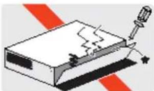
Do not open the unit
Do not open this product except when there is a specific indication in the manual. To prevent ELECTRIC shock, do not remove the cover.
This unit contains HAZARDOUS VOLTAGES and should only be opened by a trained and qualified technician. To avoid the possibility of ELECTRIC SHOCK, disconnect electric power to the product before connecting or disconnecting the LAN cables.
Figure 1: Do not open
natural_image
Illustration of a mechanical device with a spring and screwdriver, set against red diagonal stripes (no text or symbols)Lightning
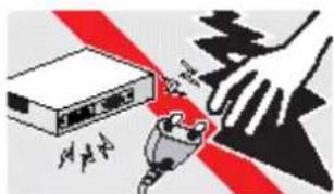
DANGER: DO NOT WORK on equipment or CABLES during LIGHTNING ACTIVITY to avoid ELECTRIC SHOCK.
Figure 2: Do not touch during a storm
text_image
Diagram illustrating a hazard warning against a device with a hand holding a key, surrounded by red and black safety stripes.Gas Leak
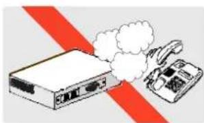
Do not use the telephone to report a gas leak in the vicinity of the leak.
Figure 3: Gas Leak
natural_image
Illustration of a network switch emitting smoke next to a telephone handset, with red diagonal stripes (no text or symbols)Avoid harmful substances
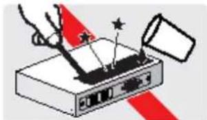
Be careful not to drop water or any other harmful substance onto the product. This could lead to fire or electric shock. If water or other substances enter the unit, unplug the power and please contact your support centre or sales stores. Do not use this product near water for example near a bathtub, washbowl, kitchen sink, laundry tub in a wet basement or near a swimming pool
Figure 4: Harmful substances
natural_image
Illustration of a hand using a tool to press or export electronic equipment via a device (no text or symbols visible)Do not cover air vents
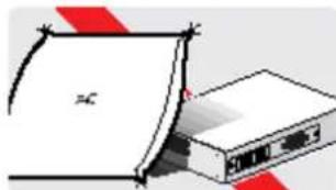
Air vents must not be blocked and must have free access to the ambient air for cooling to prevent fire caused an excessive heating.
Figure 5: Do not cover
natural_image
Illustration of a folded paper or sheet with a red-and-white graphic overlay, no visible text or symbols.Do not place in a wet, dusty, smoky or steamy environment
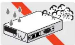
To avoid the possibility of ELECTRIC SHOCK or FIRE caused by a short in internal circuits, do not place the device in any of the above listed environments.
Figure 6: Pay attention to environmental conditions
natural_image
Illustration of a server rack with heat and smoke, no text or symbols presentDo not use with non-standard plugs or wiring
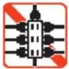
This could lead to fire, only use with industry standard plugs and wiring suitable for your territory.
Figure 7: Do not use unsuitable plugs
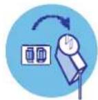
Unplug when installing or moving
to avoid the risk of electric shock.
Figure 8: Unplug
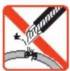
Do not damage the power cable
This could lead to fire or electric shock.
Figure 9: Do not damage power cable
Take care when handling the power cable and plug:
■ Do not strain the power cable.
■ Do not place near a heater.
■ Unplug the power cable using the plug.
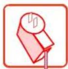
Use the power adapter supplied
Only the power adapter supplied with this unit is guaranteed to function correctly with this unit.
Figure 10: Only use the power adapter supplied with this unit.
Conditions of use
Do not use or store the device:
In direct sunlight.
■ Near a heater or in a hot place.
■ Where there could be a sudden temperature change
In a damp place or near a liquid such as water. Humidity must be less than 80%.
In areas subject to a lot of vibration.
In dusty and/or carpeted areas.
In the presence of corrosive gases.
Figure 11: Notice of use

text_image
Warning symbols for industrial pollution including sun, thermometer, steam rise, and vehicle collision hazardAvoid static shock
This product contains parts that are sensitive to static shock. Please avoid touching interface connectors with bare hands.
Figure 12: Static shock danger
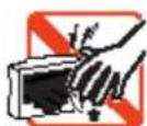
Handling
Do not drop the unit, handle with care.
Figure 13: Handling

Product care
Cleaning
Keep the product free from dust and maintain in a clean condition.
Figure 14: Before cleaning

Clean the device with a dry, soft cloth
In case of heavy dirt, clean using a soft, damp cloth with a neutral detergent then dry with a soft cloth.
Figure 15: Cleaning procedures

text_image
Three safety symbols: no hand cleaning, a weight labeled '中性' (medium level), and hands holding gloves.Do not use following materials for cleaning
oil, cleanser, thinner, petrol, wax, boiled water and powdered soap; please follow the instructions when you use a chemical duster.
Figure 16: Do not use thinner
Attention
All the information in this manual is property of Allied Telesis, please do not copy or reproduce all or part of this manual without permission. The company may change or revise all or part of this manual. It may also change the specification of the product for purposes of improvement without notice.
Emission Statement
CE Marking Warning: This is a class B product. In a domestic environment this product may cause radio interference in which case the user may be required to take adequate measures.
Please install and use it in accordance with this user manual.
Manual version
March 2004 Rev. D
About this manual
Thank you for choosing the AT-RG613/623TX Series Residential VoIP Gateway.
Please read this manual carefully and use the device correctly.
Please see below for the meaning of the icons used in this manual.
"The device", "This product", "AT-RG613", "AT-RG623", "RG613TX",
"RG623TX", "RG623" or "RG613" all refer to the Residential VoIP Gateway unit.
Table I: Icons
| Icon | Meaning |
| Useful information | |
| Indication of risk of a serious injury and/or damage to the environment | |
| As above | |
| Indication of reference page and information |
2. Contents of the package
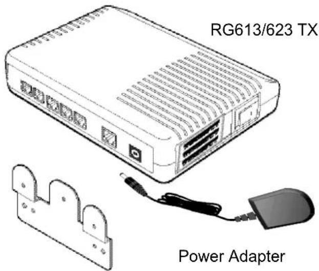
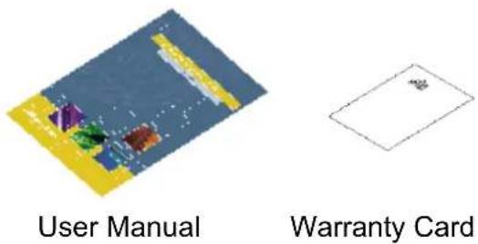
Figure 17: Contents of the package
text_image
RG613/623 TX Power AdapterWall Bracket
text_image
User Manual Warranty Card(Notice) The package does not contain screws.
The following items are included with each AT-RG613/623TX. Contact your sales representative if any items are damaged or missing.
One AT-RG613/623 TX
■ One AC/DC power adapter
One wall bracket
One AT-RG613/623 TX Series Residential VoIP Gateway User Manual
One warranty card
3. What can the AT-RG613/623TX do for you?
The AT-RG613/623TX is a Customer Premise Equipment (CPE) designed to be installed in a customer residence, it interfaces with new generation fibre/copper networks designed to support broadband communications.
Using this intelligent equipment, called a "residential gateway", you can use broadband integrated services for telephony, Internet and Internet Video.
The VoIP residential gateway is fitted with a number of ports for connection of telephones, faxes, PC's and a set top box for TV.
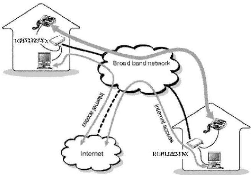
Using the internal Ethernet router you can easily build a firewall-protected Local Area Network (LAN) in your home supporting multiple PC's as well as a set top box for TV/video services (see figure below).
Figure 18: LAN connections
flowchart
graph TD
    A["Internet"] -->|RGRG263TX| B["Broad band network"]
    B -->|RGRG263TX| C["Computer"]
    B -->|RGRG263TX| D["Mobile Device"]
    B -->|RGRG263TX| E["Telephone"]
    B -->|RGRG263TX| F["Internet"]
    B -->|RGRG263TX| G["Internet access"]
    B -->|RGRG263TX| H["Internet access"]
    B -->|RGRG263TX| I["Internet access"]
    B -->|RGRG263TX| J["Internet access"]
    B -->|RGRG263TX| K["Internet access"]
    B -->|RGRG263TX| L["Internet access"]
    B -->|RGRG263TX| M["Internet access"]
    B -->|RGRG263TX| N["Internet access"]
    B -->|RGRG263TX| O["Internet access"]
    B -->|RGRG263TX| P["Internet access"]
    B -->|RGRG263TX| Q["Internet access"]
    B -->|RGRG263TX| R["Internet access"]
    B -->|RGRG263TX| S["Internet access"]
    B -->|RGRG263TX| T["Internet access"]
    B -->|RGRG263TX| U["Internet access"]
    B -->|RGRG263TX| V["Internet access"]
    B -->|RGRG263TX| W["Internet access"]
    B -->|RGRG263TX| X["Internet access"]
    B -->|RGRG263TX| Y["Internet access"]
    B -->|RGRG263TX| Z["Internet access"]
    B -->|RGRG263TX| AA["Internet access"]
    B -->|RGRG263TX| AB["Internet access"]
    B -->|RGRG263TX| AC["Internet access"]
    B -->|RGRG263TX| AD["Internet access"]
    B -->|RGRG263TX| AE["Internet access"]
    B -->|RGRG263TX| AF["Internet access"]
    B -->|RGRG263TX| AG["Internet access"]
    B -->|RGRG263TX| AH["Internet access"]
    B -->|RGRG263TX| AI["Internet access"]
    B -->|RGRG263TX| AJ["Internet access"]
    B -->|RGRG263TX| AK["Internet access"]
    B -->|RGRG263TX| AL["Internet access"]
    B -->|RGRG263TX| AM["Internet access"]
    B -->|RGRG263TX| AN["Internet access"]
    B -->|RGRG263TX| AO["Internet access"]
    B -->|RGRG263TX| AP["Internet access"]
    B -->|RGRG263TX| AQ["Internet access"]
    B -->|RGRG263TX| AR["Internet access"]
    B -->|RGRG263TX| AS["Internet access"]
    B -->|RGRG263TX| AT["Internet access"]
    B -->|RGRG263TX| AU["Internet access"]
    B -->|RGRG263TX| AV["Internet access"]
    B -->|RGRG263TX| AW["Internet access"]
    B -->|RGRG263TX| AX["Internet access"]
    B -->|RGRG263TX| AY["Internet access"]
    B -->|RGRG263TX| AZ["Internet access"]
    B -->|RGRG263TX| BA["Internet access"]
    B -->|RGRG263TX| BB["Internet access"]
    B -->|RGRG263TX| BC["Internet access"]
    B -->|RGRG263TX| BD["Internet access"]
    B -->|RGRG263TX| BE["Internet access"]
    B -->|RGRG263TX| BF["Internet access"]
    B -->|RGRG263TX| BG["Internet access"]
    B -->|RGRG263TX| BH["Internet access"]
    B -->|RGRG263TX| BI["Internet access"]
    B -->|RGRG263TX| BJ["Internet access"]
    B -->|RGRG263TX| BK["Internet access"]
    B -->|RGRG263TX| BL["Internet access"]
    B -->|RGRG263TX| BM["Internet access"]
    B -->|RGRG263TX| BN["Internet access"]
4. Product Details
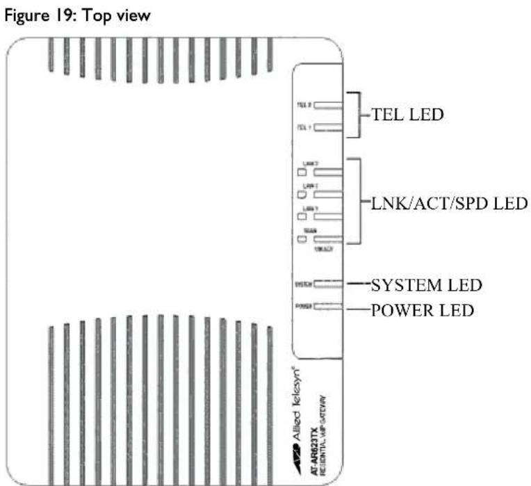
Top view of Unit
text_image
Figure 19: Top view TEL 2 TEL 1 TEL LED LNK/ACT/SPD LED LINK LINK 1 LINK 2 TEAM ON/OFF EVECH POWER SYSTEM LED POWER LED Allied Ikelesym® AT AR623TX REIDENTIAL VAP-SATEWAYTable 2: TEL LED indications RG613TX
| Led | State | Function |
| TEL | Green light on LED turns on green when you lift the receiver of the telephone or fax connected to TEL port and remains on during the call. | |
| Green light flashing The VoIP network is operating. | ||
Table 3: TEL LED indications RG623TX
| Led | State | Function |
| TEL 1 | Green light on ISDN bearer channel B1 is in use | |
| Green light flashing The VoIP network is operating. | ||
| TEL 2 | Green light on ISDN bear channel B2 is in use | |
| Green light flashing The VoIP network is operating. | ||
Table 4: Ethernet Power/System LED indications RG623TX
| LNK/ACT/SPD | Green light on | Establishment of the link as 100 BASE - TX. |
| Green light flashing | Transmission and Reception of packets as 100 BASE - TX. | |
| SYSTEM | Orange light on | In case of system error |
| Orange light flashing | Power charging | |
| POWER Green light on The device is receiving power and the voltage is within the acceptable range | ||
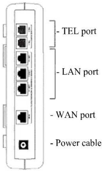
Rear view of unit
Figure 20: Back view AT-RG613TX
text_image
- TEL port - LAN port - WAN port - Power cableBack view AT-RG623TX
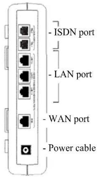
text_image
- ISDN port - LAN port - WAN port - Power cableTable 5: Ports description
| Port | Function |
| TEL PORT(RG613) | Connects analog telephone and fax with telephone cord. |
| ISDN PORT(RG623) | Connects ISDN telephone and fax with telephone cord. |
| LAN PORT (MDI-X) | Connects computer, HUB and switch with UTP cable. |
| WAN PORT | Connects UTP or fibre cable from the Wide Area Network (WAN). For Fibre, MTRJ or SC connectors are used. |
| POWER CABLE | Provides the 12V DC power to this product. This product doesn't have a power switch, you have to plug or unplug the power cable to turn the unit off. |
5. Telephones and cables
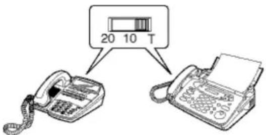
AT-RG613 - POTS Telephone and Fax Operation
Check if the dial mode is set up for tone mode (T, Tone). If not, set the switch as shown below.
Figure 21: Dial mode setting
text_image
20 10 T
Some models do not have this switch or the possibility to set up the tone mode with a button. In this case please follow the instructions telephone and fax used.
AT-RG623TX - ISDN Telephone and Fax Operations
Only telephony equipment designed to use the IDSN network may be connected to the AT-RG623TX.

The connection for ISDN telephony equipment uses the larger RJ45 connector. If the smaller RJ11 telephone cord is connected there will be excess space around the connection.
Telephone cord and UTP cable
There are 2 kinds of user connection cables: telephone cables and Unshielded Twisted Pair (UTP) cables used for data/ISDN. See Below.

This product does not include any LAN or phone cables. These must be provided by the service provider or end user.
Figure 22: Telephone cable


Note: The telephone cable uses the RJII connector

CAUTION: To reduce the risk of fire, use only No. 26AWG or larger telecommunication line cord.
Figure 23: ISDN cable

Use UTP cable category 3 or higher with RJ45 connector
Figure 24: LAN cables

Use UTP cable category 3 or higher on 10Base-T, and UTP cable category 5 or higher on 100BASE-T.

There are two types of LAN cable, straight cable and crossed cable; for the AT-RE613/623, it does not matter which of these types of LAN cable you use. The LAN interfaces on the AT-RG613/623 can autosense whether the cable is straight or crossed.

If you buy a new cable, it is recommended that you choose UTP cable - category 5 or higher.
6. Installing the AT-RG613/623TX
Installation
Before installing the AT-RG613/623TX, please read the safety information "For your Safety" in Chapter I.
When deciding the location of the device, please observe the following instructions:
■ Do not install in direct sunlight, or a damp or dusty place.
■ Do not install on an inclined or unstable surface.
■ Do not cover air vents on the side or the back of the device.
■ Do not install near a TV, radio or mobile phone.
■ Do not place anything on top of the product.
■ Do not install this product outdoors.
■ Do not touch the connector terminals.
Wall Positioning
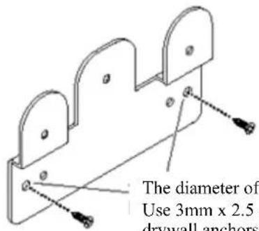
With the wall bracket in the package, you can hang the device on the wall. Before proceeding you will need to insure that the position chosen makes it possible to:
a. Connect the UTP cables and AC power cable
b. View the LED indications on the top of the unit.
You will need the following items to complete the installation of the router:
• Philips head screw driver
- 1 – 30 cm x 30cm (1 ft x 1 ft) square section of wall preferably covered with 2 cm plywood (If wall mounting the router)
- 3 – 3mm x 2.5 cm (1/8in. x 1 inch) screws
- 3 – 3 drywall anchors if mounting on drywall
Provided in the installation kit:
- I – RG613TX or RG623TX
- I – Wall mount bracket
Wall mounting the RG613/623TX:
I. Using the wall mount bracket as a template drive 3 drywall screws horizontally into the plywood towards the top and to either side of the available space. If plywood is not available, then use the wall mount bracket to mark the 3 hole locations and pre-drill for the drywall anchors, then drive the screws through the holes.
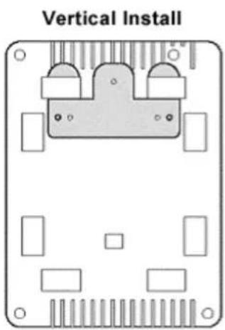
- Hang the RG613/623TX as described in Figure 26.
Figure 25: Positioning of the wall bracket
text_image
The diameter of Use 3mm x 2.5 drywall anchorsThe diameter of screw hole is 3.5mm. Use 3mm x 2.5 cm screws and, if necessary, drywall anchors.
Figure 26: Possible layouts
text_image
Vertical Install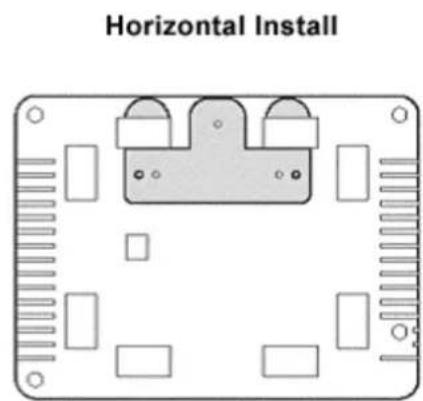
text_image
Horizontal Install
If you install the device in an elevated position, ensure it is securely connected to the wall, if not it may drop and cause injury or it may be damaged itself. Do not install where there may be vibrations, shocks or in an unsuitable place.
When you install this product on the wall it could be damaged if the unit should drop. Please be careful.

Please note that the maximum recommended operating ambient is 40^ C
7. Connecting the AT-RG613/623TX
AT-RG613TX Connecting the PSTN telephone ports
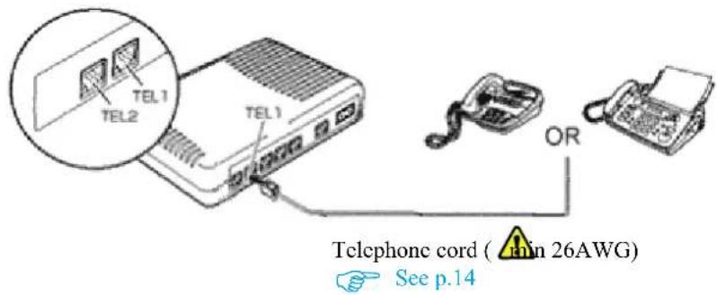
Connect PSTN (POTS) telephone and PSTN fax units to the TEL ports with the appropriate telephone cords. Push in the plug of the telephone cord to the TEL port until you hear a "click" and make sure it is correctly fixed by pulling the telephone cord lightly.
Connect to TEL I when you use only one telephone or fax machine
Figure 27: Telephone ports connection
text_image
TEL1 TEL2 TEL1 OR Telephone cord ( min 26AWG) See p.14AT-RG623TX Connecting the ISDN ports
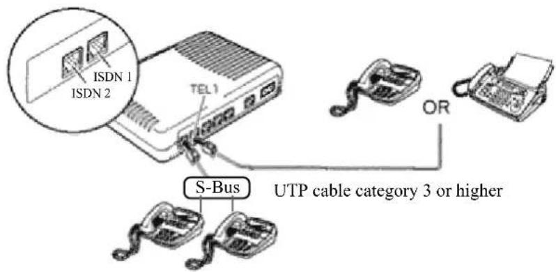
Connect ISDN telephone and ISDN fax units to the ISDN ports with the appropriate UTP cable. Push the plug of the UTP cable into the ISDN port until you hear a "click" and make sure it is correctly fixed by pulling the telephone cord lightly.
Connect to ISDN I when you use only one telephone or fax machine
Figure 28: ISDN ports connection
text_image
ISDN 1 ISDN 2 TEL 1 S-Bus UTP cable category 3 or higher ORUTP CABLE CONNECTION
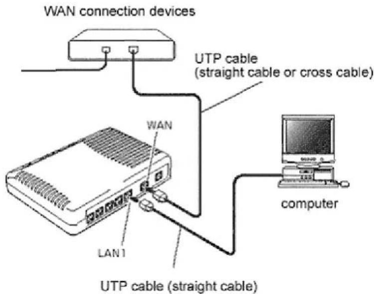
To connect devices to the WAN and LAN ports using UTP cables follow the steps below:
I. Ensure that all cables are the right length to reach each device.
2. Plug the UTP cable into the WAN port until you hear a "click" and make sure it is correctly fixed by pulling the UTP cable lightly. In the same way, connect the plug on the other end of the UTP cable to the WAN device.
The type of UTP cable (straight cable or crossed cable) depends on the kind of WAN connection device being used (e.g. cable modem / ADSL modem etc.).
- If you only need VoIP functions, your connection operation ends here. If you are connecting devices to the LAN port of this product, please follow the procedure as described in Fig 29 below.
Figure 29: UTP cable connections
text_image
WAN connection devices UTP cable (straight cable or cross cable) WAN LAN1 UTP cable (straight cable) computer- Push in the plug of the UTP cable to the LAN port until you hear a "click" and make sure it is correctly fixed by pulling the UTP cable lightly. In the same way connect the plug on the other end of the UTP cable to the network interface card of the computer, or other LAN device.
The length of each cable must be less than 100 m.
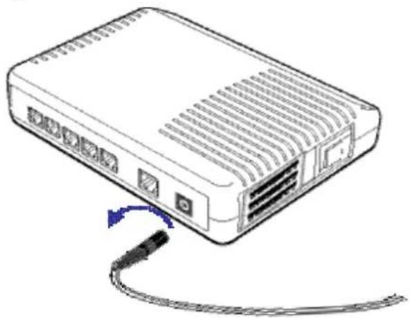
DISCONNECTING POWER SUPPLY
This product doesn't have a power switch; it automatically turns on when you connect the power cable.
When you want to turn it off, just unplug the power plug.
Figure 30: Power cable
natural_image
Line drawing of a network switch device with ports and cables (no text or symbols)Notice about functions and services
When using the VoIP telephony service there may be some services offered by the standard telephone network that are not available. Similarly, some telephone or fax functions may not be available on the VoIP network. Please contact your VoIP Telephony provider for further details.
Appendix A: Troubleshooting
This Appendix describes some of the more common problems that may occur during AT-RG613/623TX installation and use.
In the event of a problem, please look at the LED indications and then refer to this Appendix.
LED indication
10BASE-T/100BASE-TX Port LED
This indicates the status of the 10BASE-T/100BASE-TX Port.
Table 6: 10BASE-T/100BASE-TX Port LED
| LED | Colour | Statement | Detail | |
| LINK/ACT/SPD | Green | light on | Establishment of the link as 10/100 BASE – TX. flash Establishment of the link as 10/100 BASE – TX. | |
| off The link is not established. | ||||
STATUS LED
This indicates the status of the system.
Table 7: Status Led
| LED | Statement | Detail |
| SYSTEM | Orange light on | An abnormal operating condition. |
| Off | The system is working normally. | |
| Power | Green lights on | The device is receiving power and the voltage is within the acceptable range. |
| Off | The device is not receiving power. | |
TEL LED
It indicates the status of telephone.
Table 8: Status Led
| LED | Statement | Detail |
| TEL | Green light on | LED light turns green when you lift the |
| receiver of the telephone or fax connected to the TEL ports or you make a call. | |
| Green light flashes | Attached telephone or fax machine is in use. |
| Off The attached telephone is not in use. | |
Fault Finding
Is the POWER LED on?
If the power LED is off please check if the power cable is not damaged, the power cable is correctly connected and you are using the plug with the correct power voltage.
Check if the AC plug of the power cable of the product is connected correctly. This product doesn't have a power switch. To turn the unit on or off you have to plug or unplug the power cable.
Is the SYSTEM LED orange?
If the SYSTEM LED lights up orange, unplug the AC plug and plug it in again after 20 seconds. If you do not resolve the problem, unplug the power plug of this product and contact your supplier
Are the LNK/ACT/SPD LEDs on?
Check if the power of the connected device is on, check that there are no problems with the network interface cards installed in the attached devices, also check if the cables are correctly connected to the network interface cards and that the correct cable is being used (i.e. straight or crossover).
Check also if the length of the cable is over the limit. UTP cable must be less than 100 m.
To connect this product to a computer, you must use a straight cable. To connect this product to a HUB or switch, you must use a crossover cable. Please check if you're using the correct cable.
■ Do you have a problem with the UTP cable?
Swap out with a known good cable.
■ Does TEL LED light up when you lift up the receiver?
Please ensure that the telephone cable is connected correctly, that the correct cable is being used and that the cable is not damaged.
■ Do you have a problem with the telephone cord?
Swap out with a known good telephone cord.
Check if the setting of the dial mode for the telephone and fax is correct, follow the instructions of the telephone and/or fax device.
Appendix B: Technical Specifications
Product Specifications AT-RG613TX
| Supported standards | |
| IEEE 802.3 10 BASE-T, | |
| IEEE 802.3u 100 BASE-TX, | |
| RFC 791, RFC1144, RFC1112, RFC2236, RFC 2516, | |
| RFC 1334, RFC 1994, RFC 1631, RFC 2131, | |
| RFC 3261, RFC 1350, RFC 318, RFC 826, | |
| RTP/RTCP, H.323 4.0, MGCP/NCS 1.0, SNMP v1 | |
| Interface | |
| WAN port 1 10/100BASE-TX (8 pin RJ45 connector) | |
| LAN port 3 10/100BASE-TX (8 pin RJ45 connector) | |
| TEL port 2 FXS (6 pin RJ11 connector) | |
| Power | |
| AC Input voltage AC100-240V | |
| Standard Frequency 50-60Hz | |
| AC Input current 0.1A (240V) | |
| Average power 9.7W (Max.9.8W) | |
| Average heat 8.3kcal/h (Max. 8.4kcal/h) | |
| Environment condition | |
| Storage Temperature -20° – 40°C | |
| Humidity Less than 95% (non condensing) | |
| Operating Temperature 0° - 40°C | |
| Humidity Less than 80% (non condensing) | |
| Size (with no projection) | |
| 200(W) x 150 (D) x48 (H) mm | |
| Weight | |
| 510g | |
| MAC address table size | |
| 1024 | |
| Memory Capacity | |
| RAM memory 16Mbyte | |
| Flash memory 4Mbyte | |
| Product Certification | |
| CE, FCC, UL | |
Compliances
IEC60950, ULI950, EN 60950
EN55022, EN61000-3-2, EN61000-3-3, EN55024
FCC CFR 47 Part 15 Sub B
Product Specifications AT-RG623TX
| Supported standards | |
| IEEE 802.3 10 BASE-T, | |
| IEEE 802.3u 100 BASE-TX, | |
| RFC 791, RFC1144, RFC1112, RFC2236, RFC 2516, | |
| RFC 1334, RFC 1994, RFC 1631, RFC 2131, | |
| RFC 3261, RFC 1350, RFC 318, RFC 826, | |
| RTP/RTCP, H.323 4.0, MGCP/NCS 1.0, SNMP v1, | |
| I.430, Q.921, Q.931 | |
| Interface | |
| WAN port 1 10/100BASE-TX (8 pin RJ45 connector) | |
| LAN port 3 10/100BASE-TX (8 pin RJ45 connector) | |
| TEL port 1 ISDN S/T (8 pin RJ45 connector) | |
| Power | |
| AC Input voltage AC100-240V | |
| Standard Frequency 50-60Hz | |
| AC Input current 0.1A (240V) | |
| Average power 7.7W (Max.8W) | |
| Average heat 11.28kcal/h (Max. 11.39kcal/h) | |
| Environment condition | |
| Storage Temperature -20° – 40°C | |
| Humidity Less than 95% (non condensing) | |
| Operating Temperature 0° - 40°C | |
| Humidity Less than 80% (non condensing) | |
| Size (with no projection) | |
| 200(W) x 150 (D) x48 (H) mm | |
| Weight | |
| 510g | |
| MAC address table size | |
| 1024 | |
| Memory Capacity | |
| RAM memory 16Mbyte | |
| Flash memory 4Mbyte | |
| Product Certification | |
| CE | |
| Compliances | |
| IEC60950, EN 60950 | |
| EN55022, EN61000-3-2, EN61000-3-3, EN55024 | |
Appendix C: Contact information
In the event of any problem please contact your service provider or installer.