
DHB-E 13 A - Uncategorized STIEBEL ELTRON - Free user manual and instructions
Find the device manual for free DHB-E 13 A STIEBEL ELTRON in PDF.

| Product Type | Electric Tankless Water Heater |
| Brand | Stiebel Eltron |
| Model | DHB-E 13 A |
| Power Rating | 13 kW |
| Power Supply | 400 V AC 3-phase / 230 V AC single-phase |
| Current Rating | 18 A (3-phase) / 56 A (single-phase) |
| Water Connection | 3/4 inch (DN20) |
| Dimensions (H x W x D) | 400 mm x 200 mm x 120 mm |
| Weight | 3.5 kg |
| Temperature Range | 30 °C to 60 °C |
| Flow Rate | Up to 6.5 L/min at 40 °C rise |
| Control Type | Electronic with LED display |
| Features | Constant temperature, overload protection, anti-scald |
| Safety | IP25 splash-proof, thermal cutoff, dry-run protection |
| Energy Class | A+ |
| Installation | Wall-mounted, indoor use only |
| Maintenance | Descaling recommended every 2-3 years |
| Spare Parts Availability | Yes, through authorized dealers |
| Warranty | 2 years (extendable) |
Frequently Asked Questions - DHB-E 13 A STIEBEL ELTRON
User questions about DHB-E 13 A STIEBEL ELTRON
0 question about this device. Answer the ones you know or ask your own.
Ask a new question about this device
Download the instructions for your Uncategorized in PDF format for free! Find your manual DHB-E 13 A - STIEBEL ELTRON and take your electronic device back in hand. On this page are published all the documents necessary for the use of your device. DHB-E 13 A by STIEBEL ELTRON.
USER MANUAL DHB-E 13 A STIEBEL ELTRON
OPERATING AND INSTALLATION
Electronically controlled instantaneous water heater
1.1 Safety instructions 2
1.2 Other symbols in this documentation 3
1.3 Units of measurement 3
- Safety 3
2.1 Correct use 3
2.2 Safety instructions 3
2.3 CE designation 3
-
Appliance description ____ 4
-
Operation 4
4.1 Temperature selector ____ 4
4.2 Draw-off capacities 4
4.3 Thermostatic valve 4
4.4 Temperature limit/Anti-scalding protection ____ 4
-
Cleaning, care and maintenance 4
-
Troubleshooting 4
INSTALLATION
- Safety 5
7.1 General safety instructions 5
7.2 Instructions, standards and regulations 5
7.3 Water installation 5
7.4 Risk of frost 5
- Appliance description 6
8.1 Standard delivery 6
8.2 Installation 6
8.3 Temperature limiting/anti-scalding protection 6
8.4 Installation versions 6
8.5 Accessories 6
- Installation 7
9.1 Installation information 7
- Installation 7
10.1 Installation location 7
10.2 Installation 8
10.3 Installation versions 10
-
Commissioning 13
-
Appliance handover 13
-
Troubleshooting 14
13.1 Display options LED diagnostic "traffic lights" ____ 14
13.2 Fault table 14
- Specification 15
14.1 Dimensioned drawing 15
14.2 Wiring diagram 15
14.3 Mixed water volume / outlet volume 15
14.4 Application areas 15
14.5 Pressure drop 15
14.6 Fault conditions 15
14.7 Country-specific approvals and certifications 15
14.8 Specification 16
WARRANTY | ENVIRONMENT AND RECYCLING
OPERATION
1. General information
The chapter "Operation" is intended for appliance users and heating contractors.
The chapter "Installation" is intended for heating contractors.

Note
Read these instructions carefully before using the appliance and retain them for future reference.
Pass on the instructions to a new user if required.
1.1 Safety instructions
1.1.1 Structure of safety instructions

KEYWORD Type of risk
Here, possible consequences are listed that may result from failure to observe the safety instructions.
▶ Steps to prevent the risk are listed.
1.1.2 Symbols, type of risk
Symbol Type of risk

Injury

Electrocution

Burns (burns, scalding)
1.1.3 Keywords
KEYWORD Meaning
| DANGER | Failure to observe this information will result in serious injury or death. |
| WARNING | Failure to observe this information may result in serious injury or death. |
| CAUTION | Failure to observe this information may result in non-serious or minor injury. |
1.2 Other symbols in this documentation

Note
General information is identified by the symbol shown on the left.
▶ Read these texts carefully.
Symbol Meaning
| ! |
Material damage
(appliance, consequential and environmental damage)

Appliance disposal
This symbol indicates that you have to do something. The action you need to take is described step by step.
1.3 Units of measurement

Note
All measurements are given in mm unless stated otherwise.
2. Safety
2.1 Correct use
The appliance is a pressure appliance for heating domestic hot water.
Any other use beyond that described shall be deemed inappropriate. Observation of these instructions is also part of the correct use of the appliance. Any changes or conversions to the appliance void any warranty.
2.2 Safety instructions
Observe the following safety information and instructions.
Only heating contractors should install and commission the appliance.
The contractor is responsible for adherence to all currently applicable regulations during installation and commissioning.
Operate this appliance only if it is fully installed and all safety equipment is fitted.

CAUTION Burns
There is a risk of scalding at outlet temperatures in excess of 43^ C.

CAUTION Burns
If operating with preheated water, e.g. from a solar thermal system, the DHW temperature may vary from the selected set temperature.

WARNING Injury
Where children or persons with limited physical, sensory or mental capabilities are to be allowed to control this appliance, ensure that this will only happen under supervision or after appropriate instructions by a person responsible for their safety. Children should be supervised to ensure that they do not play with the appliance.

Material damage
Do not operate the appliance following an interruption to the water supply. This can destroy the bare wire heating system. Run water for at least a minute before restarting the appliance (see chapter "Troubleshooting").
2.3 CE designation
The CE designation shows that the appliance meets all the essential requirements:
- Low Voltage Directive (Council Directive 2006/95/EC).
- Electromagnetic Compatibility Directive The maximum permissible mains impedance is indicated in chapter "Specification / Data table".
3. Appliance description
This electronically controlled instantaneous water heater with automatic output matching keeps the outlet temperature constant. This occurs regardless of the inlet temperature up to the output limit. The DHW outlet temperature can be freely selected.
The bare wire heating system is suitable for hard and soft water areas; it has low susceptibility to scale build-up. The heating system ensures quick and efficient DHW availability.
4. Operation
4.1 Temperature selector
DHB-E ... SLi
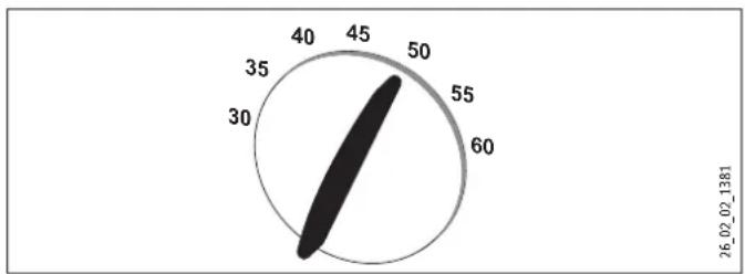
gauge
| Value | |---| | 55 | | 45 | | 60 | | 35 | | 30 | 26_02_02_1381 |DHB-E ... A
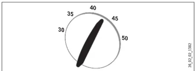
gauge
| Value | |---| | 45 | | 35 | | 40 | | 30 | | 50 | 26_02_02_1382Should the outlet temperature fail to reach the required level with the draw-off valve fully open and the temperature selector set to maximum, then more water flows through the appliance than can be heated by the heating element.
▶ Reduce the flow rate with the draw-off valve.
4.2 Draw-off capacities
Subject to season, varying maximum mixed water or draw-off capacities result from different cold water temperatures. Further information can be found in the chapter "Specification".
4.3 Thermostatic valve
We recommend adjusting the appliance to the maximum temperature setting.
4.4 Temperature limit/Anti-scalding protection
The maximum outlet temperature for the appliance can be limited to 43 °C. Refer in this case to your local heating contractor.
5. Cleaning, care and maintenance
▶ Never use abrasive or corrosive cleaning agents. A damp cloth is sufficient for cleaning the appliance.
Maintenance work, such as checking the electrical safety, must only be carried out by a heating contractor.
6. Troubleshooting
Material damage
Following an interruption of the water supply, recommission the appliance by carrying out the following steps, in order to prevent the destruction of the bare wire heating system.
▶ Disconnect the appliance from the power supply by removing the fuses/tripping the MCBs.
▶ Open the tap until the appliance and its upstream cold water inlet line are free of air.
▶ Switch the mains power back ON again.
| Fault Cause Remedy | ||
| The appliance will not start in spite of a fully open DHW valve. | There is no voltage. | Check the fuse/MCB in your fuse box/distribution panel. |
| Starting volume is not achieved. The perlator in the tap or shower head is scaled up or dirty. | Clean and/or descale the perlator or the shower head. | |
| The heating system is faulty. | Contact your heating contractor. | |
| The air sensor detects air in the water and briefly switches the heater off. | The appliance restarts automatically after one minute. | |
| Required temperature >45 °C is not achieved. | Cold water inlet temperature is >45 °C. | Reduce the cold water inlet temperature. |
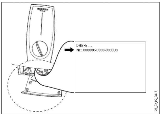
If you cannot remedy the fault, contact your heating contractor. For better and faster help, provide him with the serial number from the type plate (no. 000000-0000-000000):
INSTALLATION
7. Safety
7.1 General safety instructions
All required steps to complete commissioning must be carried out by a heating contractor. During this process, these installation instructions must be observed.
We guarantee trouble-free function and operational reliability only if the original accessories and spare parts intended for the appliance are used.
7.2 Instructions, standards and regulations

Material damage
Observe the type plate. The stated voltage must match the mains voltage.

WARNING Risk of electrocution
All electrical connection and installation work must be conducted in accordance with VDE regulations (DIN VDE 0100) [or local regulations], the rules of your local power supply utility and relevant national and local regulations.

WARNING Risk of electrocution
Connection to the power supply is only possible as a fixed connection. The appliance must be able to be separated from the mains power supply by an isolator that disconnects all poles with at least 3 mm contact separation.

Note
Observe all national and local instructions and regulations relating to water connection.
- The protection IP 25 (hoseproof) can only be ensured with a correctly fitted cable grommet.
- The specific electrical resistant of the water used must not fall below that stated on the type plate. In a linked water network, observe the lowest electrical water resistance (see chapter "Application areas"). Your water supply utility will advise you of the specific electrical water resistance or conductivity.
7.3 Water installation
7.3.1 Cold water line
Permissible materials: Galvanised steel pipe, stainless steel pipe, copper pipe or plastic pipe.
7.3.2 DHW line
Permissible materials: Stainless steel pipe, copper pipe or plastic pipe.

Material damage
If plastic pipework is used, observe the most extreme operating and fault conditions that can occur in the appliance.

Note
Observe the plastic pipe manufacturer's instructions.
- A safety valve in the hot water pipe is not permissible.
- Never operate with valves intended for open vented appliances.
7.4 Risk of frost
The installation of the appliance must be carried out in a room free from the risk of frost.
▶ Store the dismantled appliance in a room free from the risk of frost, as water residues remaining inside the appliance can freeze and cause damage.
8. Appliance description
The bare wire heating system is suitable for hard and soft water areas. The heater has low susceptibility to scale build-up.
The appliance is suitable for heating cold water or for reheating preheated water. For temperatures, see chapter "Specification / Data table".
The max. inlet temperature for reheating must not be exceeded. There will be no reheating, if the inlet temperatures exceed this maximum value.
Observe the "Max. inlet temperature". The appliance can be damaged at higher temperatures. If a "central thermostat" is installed (see chapter "Installation / Accessories"), you can limit the "Max. inlet temperature".
The outlet temperature can be infinitely adjusted. The electronic control unit enables automatic matching of the electrical output corresponding to the selected temperature subject to the actual throughput.
8.1 Standard delivery
- Mounting bracket
- Installation template
- Twin nipple
- Cross-piece
- Tee
- Flat packing
- Sieve
- Flow limiter
- Plastic profile washer
- Plastic cap
- Flexible plastic couplings
- Cap and back panel guides
8.2 Installation
The following conditions have been prepared for the appliance at the factory:
- Power supply from "below", installation on unfinished walls
- Water connection, installation on unfinished walls
The appliance must be fitted vertically, over or undersink, to a solid wall.
8.3 Temperature limiting/anti-scalding protection
The maximum temperature can be limited to 43 °C via the user interface on the appliance cap. The following steps are necessary for this procedure:
▶ Remove the appliance cap.
▶ Remove the electronic PCB from the user interface on the appliance cap. Be careful of the snap-on hooks.
▶ Move the plug from left to right (position "43 °C").
▶ Refit the user interface, ensuring the snap-on hooks click place. Observe the positions of the pushbutton and shaft.

CAUTION Burns
If operating with preheated water, the set temperature limit and anti-scalding protection may be ineffective.
In this case, restrict the temperature at the upstream central thermostatic valve; see chapter "Accessories".
8.4 Installation versions
The following installation versions are possible/permissible:
- Power supply for unfinished walls - from above
- Power supply for finished walls
- Water installation for finished walls
- Installation with repositioned appliance cap
- Installation for offset tiles
- Installation of a load shedding relay
8.5 Accessories
Taps
- WKMD - twin-lever pressure-tested kitchen tap
- WBMD - twin-lever pressure-tested bath tap
Plug G 12 A
These plugs are required if you use twin-lever pressure-tested taps for finished walls other than the ones recommended by us.
Installation sets for installation on finished walls
- Solder fitting - copper pipe for solder connection ∅ 12 mm.
- Compression fitting - copper pipe.
- Compression fitting - plastic pipe (suitable for Viega: Sanfix-Plus or Sanfix-Fosta).
Universal mounting frame
- Mounting frame with electrical wiring.
Pipe set for undersink appliances
The set for undersink installation is required if you want to have the water connections (G 38 A) above the appliance.
Pipe set, offset installation
This pipe set with pipe bends is required if you want to have the appliance vertically offset against the water connection by approx. 90 mm downwards.
Pipe set for replacing a gas water heater
This pipe set is required if the installation has existing gas water heater connections (cold water connection on the left and DHW connection on the right).
DHB replacement pipe set
2 water couplings. These allow the appliance to be connected to the available water plug-in connections of a DHB.
Load shedding relay LR 1-A
The load shedding relay for installation in the electric distribution board enables priority control of the instantaneous water heater when electric storage heaters are being operated simultaneously, for example.
ZTA 3/4 - Central thermostatic valve
Thermostatic valve for centralised premixing, e.g. an instantaneous water heater in conjunction with a solar thermal system.
9. Installation
9.1 Installation information
9.1.1 Flow pressure
If the flow rate required for the appliance to switch on is not achieved even with the tap fully open, remove the flow limiter. Replace it with the plastic profile washer supplied. If required the pressure in the water installation can also be raised.

Note
For the thermostatic valve to function correctly, the flow limiter for this valve must not be replaced with the plastic profile washer.
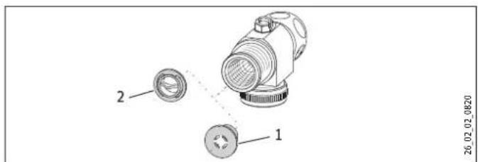
1 Flow limiter
2 Plastic profile washer
9.1.2 Flexible water connection lines
If the appliance is connected with flexible water connection lines, ensure that the bayonet fittings of the pipe bends do not become twisted inside the appliance.
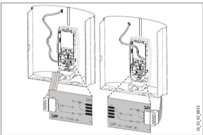
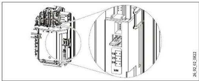
9.1.3 Appliance with changeover connected load
The appliance DHB-E 18/21/24 SLi is set to 21 kW when delivered. If the appliance is installed with a different output, take the following steps:
▶ Re-plug the coding card according to the selected output; for selectable output and fuse protection of the appliance see "Specification".
▶ Mark the selected output on the type plate using a permanent marker.
▶ Install the flow limiter with a rating corresponding to that of the appliance. The colour of the flow limiter is given in the table "Specification".
natural_image
Technical line drawing of an electrical enclosure with internal components and a close-up view (no text or symbols)10. Installation
10.1 Installation location
The appliance is exclusively designed for installation on a solid wall. Ensure that the wall has a sufficient load-bearing capacity.
Always install the appliance vertically (over or undersink) in a room free from the risk of frost.
10.1.1 Undersink
10.2.1 Opening the appliance
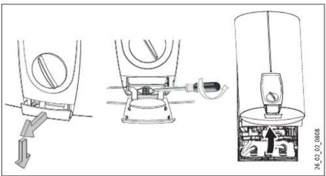
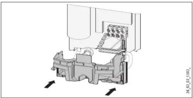
10.2.2 Removing the back panel
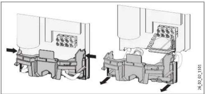
natural_image
Technical diagram of a mechanical assembly with two views showing internal components and directional arrows (no text or symbols)▶ Press the two locking hooks on the r.h. and l.h. side and remove the lower part towards the front.
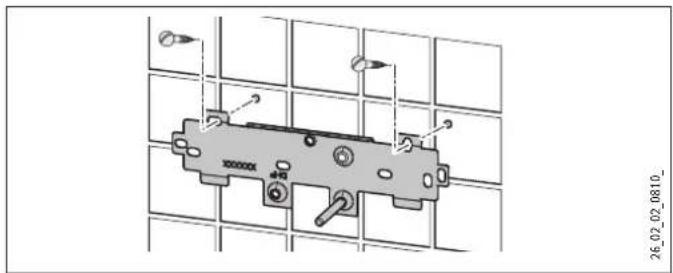
10.2.3 Fitting the mounting bracket
▶ Mark out the holes for drilling using the installation template. If the appliance is to be installed with water connections for finished walls, the fixing hole in the lower part of the template must also be marked out.
Drill the holes and secure the mounting bracket with two screws and two rawl plugs. The screws and rawl plugs are not part of the standard delivery.
10.2.4 Fitting the power cable
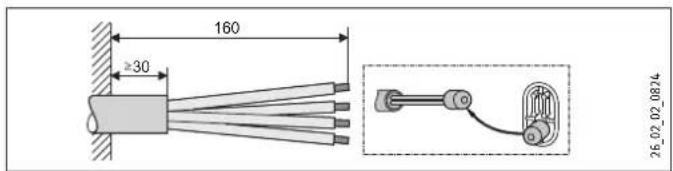
▶ Prepare the power cable.
▶ Use the plastic cap as an installation aid.
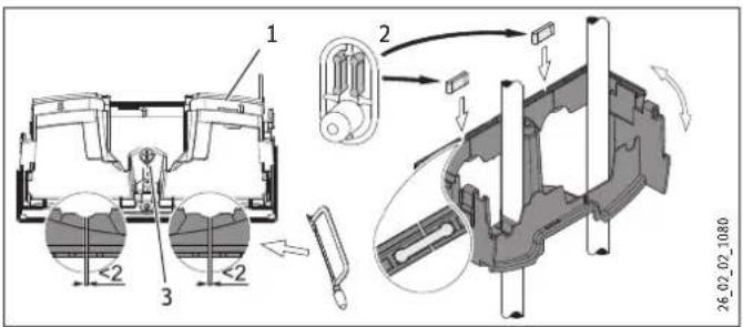
10.2.5 Inserting the twin nipples
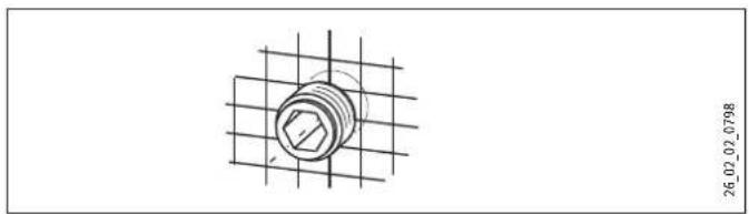
natural_image
Technical drawing of a bolted joint on a grid background (no text or symbols)10.2.6 Preparing the water connection
- Secure the tee and cross-piece to the twin nipples with flat packing.
▶ Thoroughly flush the cold water supply line.

Note
Never use the three-way shut-off valve to reduce the flow rate; it is only designed to shut off a circuit.
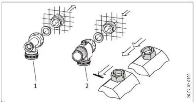
1 Tee
2 Cross-piece
10.2.7 Fitting the sieve
▶ Fit the sieve provided in the cold water inlet of the appliance.

Note
The sieve must always be fitted for the function of the appliance to be guaranteed. If an appliance is being replaced during installation, ensure that a sieve is available.
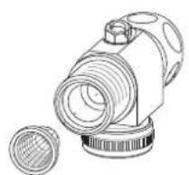
natural_image
Line drawing of a mechanical device with a circular component and a separate cylindrical part (no text or symbols)26_02_02_0856
10.2.8 Installing the DMB flow limiter
▶ Position the flow limiter provided in the cold water inlet of the appliance.
A second flow limiter is provided with the DHB-E 18/21/24 SLi. Install the flow limiter with an output corresponding to that of the appliance.
Flow limiter, see "flow rate limit" in chapter "Specification":
4.0 l/min = pink
7.5 l/min = blue
8.5 l/min = green

26_02_02_0857
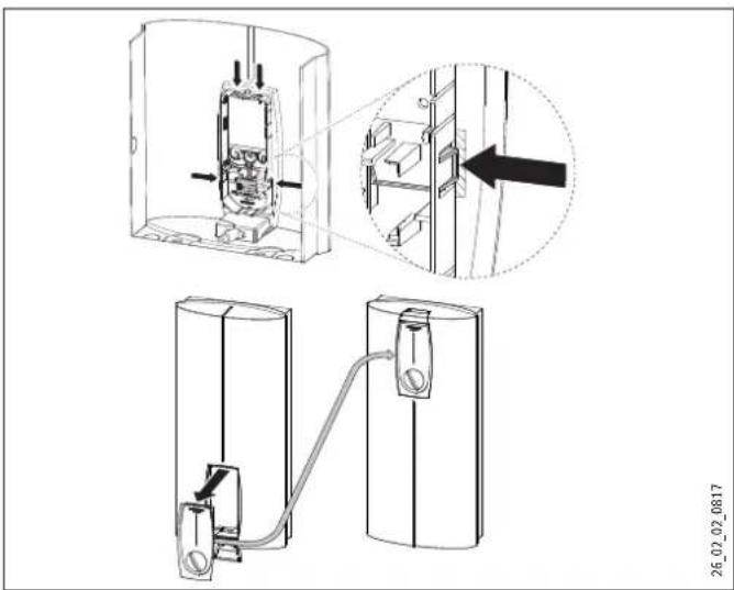
10.2.9 Mounting the appliance
The cable grommet pointing towards the wall may hinder the mounting of the appliance close to the wall. To prevent such problems, it is advisable to briefly press the cable grommet from behind into the back panel, to reduce the stiffness or the grommet.
Remove the fixing toggle from the upper part of the back panel (diagram "Mounting the appliance").
Route the power cable from behind through the cable grommet until it rests against the cable sheath. Align the power cable. If the cross-section of the power cable is greater than 6 mm, enlarge the hole in the cable grommet (see also "Power supply for larger cross-sections").
▶ Push the appliance over the stud of the mounting bracket, so that it breaks through the soft seal. If necessary pierce the soft seal with a screwdriver.
▶ Put the fixing toggle onto the stud of the mounting bracket that penetrates the back panel.
▶ Press the back panel firmly into place and lock the fixing toggle by turning it through 90°.
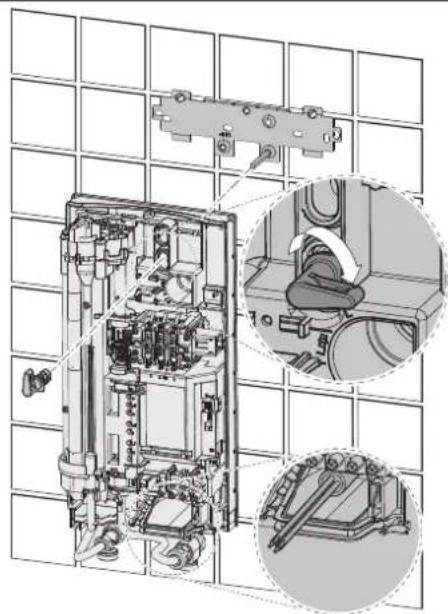
natural_image
Technical diagram of an electrical enclosure with internal components and a close-up inset showing mechanical assembly (no text or labels)26_02_02_0811
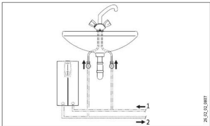
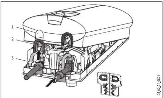
10.2.10 Finalising the water connection
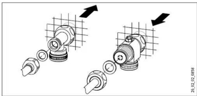
natural_image
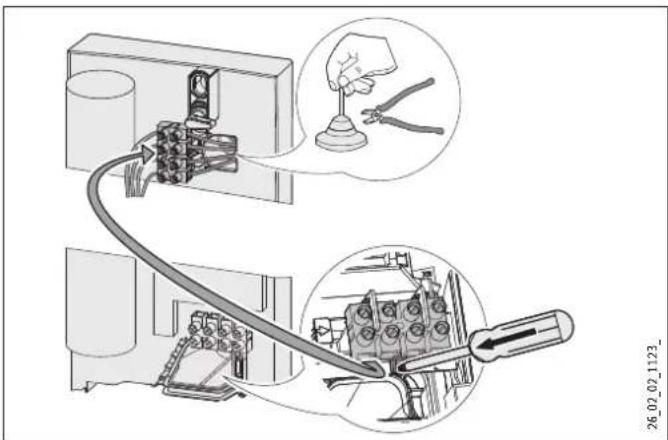
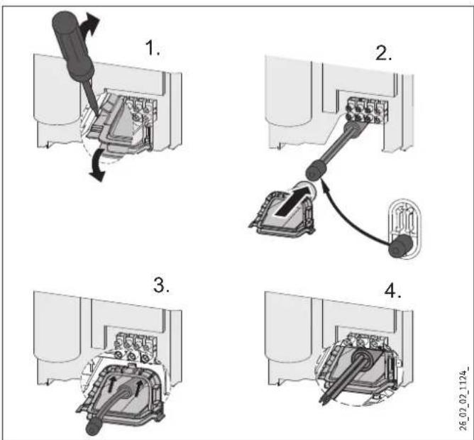
Mechanical assembly diagram showing two connected components with directional arrows indicating motion (no text or symbols)10.2.11 Connecting the power supply
▶ Connect the power cable to the mains terminal (see chapter "Wiring diagram").

WARNING Risk of electrocution
Ensure that the appliance is connected to earth.
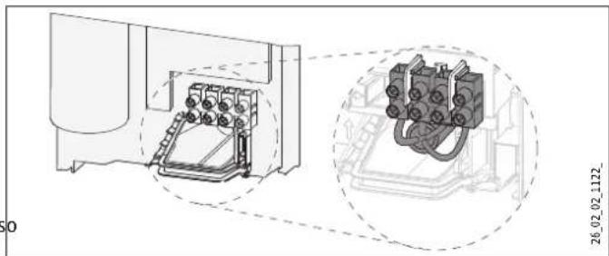
natural_image
Technical line drawing of a mechanical assembly with two views: one showing internal components and the other showing a complex electrical component (no text or symbols present)10.2.12 Fitting the lower back panel
natural_image
Technical diagram of a mechanical assembly with directional arrows indicating movement or force (no text or symbols present)10.2.13 Completing the installation process
▶ Align the mounted appliance by loosening the fixing toggle, aligning the power supply and back panel, and then retightening the fixing toggle. If the back panel of the appliance is not flush against the wall, the appliance can be fixed with a screw in the lower part.
10.3 Installation versions
10.3.1 Power supply from above for unfinished walls
The following diagram shows the dimensions for the power supply from above.
To connect the power supply, take the following steps:
▶ Open out the cable grommet to match the cross-section of the power cable.
▶ Push down and remove the locking hook that secures the mains terminal.
▶ Move the mains terminal in the appliance from the bottom the top and click into place.
10.3.2 Power supply for finished walls
The appliance can also be connected if the power supply has been routed over finished walls. This applies to the connection from below and above. Take the following steps:
▶ Cut or break knock-outs in the back panel and appliance cap. Possible knock-out points can be seen in the diagram "Dimensions for power supply".

Note
If the appliance has been connected with a power supply on finished walls, the type of protection on the type plate must be changed from IP 25 to IP 24. Use a permanent marker for that.
▶ Cross out "IP 25" and mark the box "IP 24".
10.3.3 Power supply for large cross-sections
to If cables with a large cross-section are used, the cable grommet can be fitted after the appliance has been installed. Take the following steps:
▶ Before installing the appliance, use a screwdriver to push the cable grommet out.
▶ Push the appliance over the stud of the mounting bracket, so that it breaks through the soft seal.
▶ Push the fixing toggle onto the stud of the mounting bracket that penetrates the back panel.
▶ Press the back panel firmly into place and lock the fixing toggle by turning it through 90°.
▶ Push the cable grommet over the power cable. For this, use the installation aid. For a power cable of 10 or 16 mm ^2 , the hole in the cable grommet must be enlarged. Click the cable grommet into place in the back panel.
10.3.4 Connecting a load shedding relay
Install the load shedding relay in conjunction with other electric appliances, e.g. electric storage heaters. The relay responds when the instantaneous water heater starts. The load shedding relay is available from Stiebel Eltron as a special accessory.

Note
Connect the phase that switches the load shedding relay to the indicated terminal of the mains terminal in the appliance.
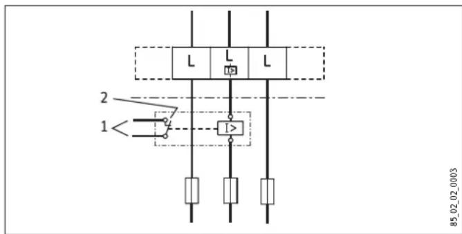
1 Control cable to the contactor of the second appliance (e.g. electric storage heater).
2 Control contact, opens when switching the instantaneous water heater on.
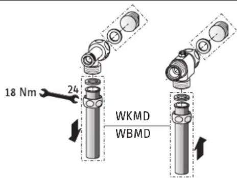
10.3.5 Water installation for finished walls
Suitable pressure taps WKMD or WBMD for installation on finished walls are available as special accessories.
▶ Fit the water plugs with gaskets to seal the connection (below the plaster). With Stiebel Eltron pressure taps, plugs and gaskets are part of the standard delivery. For third party pressure taps, plugs and gaskets can be ordered as special accessories.
▶ Install the tap.
▶ Push the lower part of the back panel under the connection pipes of the pressure tap and click it into place in the back panel.
▶ Secure the connection pipes to the appliance.
26_02_02_0528_
10.3.6 Water installation for finished walls with solder/compression fitting
With the special accessories "solder fitting" or "compression fitting" (see "Accessories"), copper or plastic pipes can be connected in installations for finished walls.
With special accessory "solder fitting", a threaded connection with on-site 12 mm copper pipes is possible. For this the following steps are required:
▶ Push the union nuts over the connection pipes.
▶ Solder the inserts to the copper pipes.
▶ Push the lower part of the back panel under the connection pipes and click it into place in the back panel.
▶ Secure the connection pipes to the appliance.

Note
Observe the valve manufacturer's installation instructions.
10.3.7 Water installation for finished walls, fitting the appliance cap
The following steps are necessary to complete the appliance cap installation.
▶ Cleanly break out the knock-out in the appliance cap. If necessary, use a file.
▶ Break the tabs out of the cap guides.

Note
The appliance can be sealed by fitting the cap guides with tabs if the tap pipes are slightly offset. The back panel guides are not required in this case.
▶ Click the cap guides provided into place in the knock-outs.
▶ Position the back panel guides on the pipes and push them together. Then push the guides until they meet the back panel.
- Secure the back panel at the bottom with a screw. This is also relevant if flexible water supply systems are used.
1 Knock-out
2 Cap guides
3 Back panel guides
10.3.8 Installing lower part of back panel
If using threaded connections for finished walls, the lower part of the back panel can also be installed after fitting the taps/valves. To do this, carry out the following steps:
- Cut open the lower part of the back panel.
- Fit the lower part of the back panel by bending it out at the sides and guiding it over the pipes.
▶ Insert the connection pieces from behind into the lower part of the back panel.
▶ Click the lower part of the back panel into place.
▶ Secure the lower part of the back panel with a screw.
1 Lower part of back panel
2 Connection piece from the pack
3 Screw
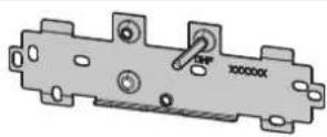
10.3.9 Installation in case of appliance replacement
An existing mounting bracket can be used when replacing Stiebel Eltron appliances (except "DHF"). For this, open a suitable knock-out in the back panel for the stud of the existing mounting bracket.
If the appliance is being installed in place of a DHF, move the stud on the mounting bracket as shown in the diagram "Mounting bracket for DHF appliance replacement". The stud cuts its own groove. Then turn the mounting bracket through 180° to be mounted on the wall. The logo "DHF" is then turned towards the reader.
If replacing a third party appliance, suitable holes for rawl plugs can be used.
26_02_02_0815
10.3.10 Undersink installation with turned appliance cap
The appliance cap can be positioned on the back panel turned through 180°. This particularly advantageous for undersink installation. For this take the following steps:
▶ Remove the user interface from the appliance cap by pressing the locking hooks.
▶ Turn the appliance cap and click the user interface into place, ensuring that all locking hooks click into place. To install the user interface more easily, press against the inner side of the appliance cap (in the shaded area, see diagram "Appliance cap for undersink installation").
Material damage
Never install a user interface with a faulty locking hook. Otherwise the safety of the appliance cannot be guaranteed.
▶ Plug the set value transducer cable into the "set temperature" PCB; see "Commissioning".
▶ Hook the appliance cap in at the bottom and pivot it up onto the back panel. Ensure the all-round seal of the back panel sits tightly by pushing the cap gently forwards and back.
▶ Close the appliance with the screw in the cap.
natural_image
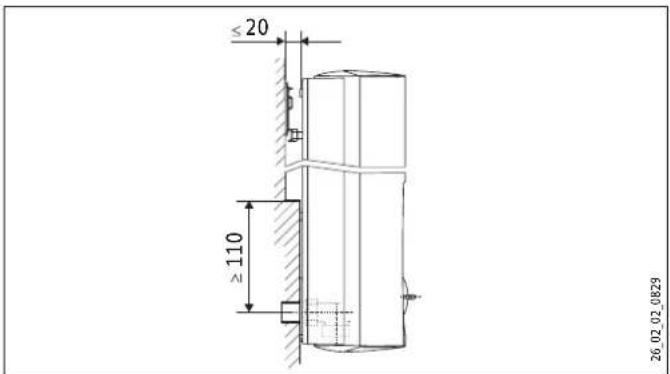
Technical line drawing of a mechanical assembly with exploded and assembled views (no text or symbols)10.3.11 Installation for offset tiles
This appliance can be installed where tiles are offset. See diagram for maximum tile offset and minimum contact area of the appliance. Adjust the wall clearance and lock the back panel with the fixing toggle by turning it clockwise through 90°.
11. Commissioning

WARNING Risk of electrocution
Commissioning must only be carried out by an authorised contractor in accordance with safety regulations.
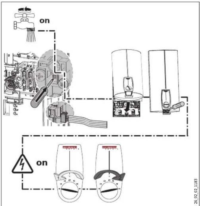
▶ Open and close all connected draw-off valves several times, until all air has been vented from the pipework and the appliance.
▶ Activate the safety pressure switch at flow pressure by pressing the reset button. The appliance is supplied with the safety pressure limiter deactivated.
▶ Push the temperature selector plug into the "set temperature" PCB.
▶ Fit the appliance cap and secure with a screw.
▶ Switch the mains power ON.
▶ Calibrate the temperature by turning the temperature selector as far as possible clockwise and then anti-clockwise.
▶ Check the appliance function.
▶ Remove the protective foil from the user interface.
12. Appliance handover
Explain the appliance function to the user and familiarise him/her with its operation.
▶ Make the user aware of potential dangers, especially the risk of scalding.
▶ Hand over these instructions to the user for safe-keeping.
13. Troubleshooting

WARNING Risk of electrocution
To test the appliance, it must be supplied with power.
13.1 Display options LED diagnostic "traffic lights"
Display options
| red illuminates in case of faults | |
| yellow illuminates when the appliance is heating water | |
| green flashing: The appliance is supplied with power |
13.2 Fault table
| Fault / LED diagnostic "traffic light" display | Cause Remedy | ||
| The appliance does not start. | The shower head / perlators are scaled up. | Descale or if necessary replace the shower head / perlators. | |
| Inadequate flow rate. The sieve in the appliance is dirty. Clean the sieve. | |||
| Set temperature is not achieved. | One phase down. | Check the MCB/fuse in your fuse box. | |
| Heating does not switch on. | The air sensor detects the presence of air in the water and briefly switches the heater off. | The appliance restarts after one minute. | |
 | No hot water and no "traffic light" display. | The MCB/fuse has responded/blown. | Check the MCB/fuse in your fuse box. |
| Safety pressure limiter AP 3 has tripped. | Remove the cause of the fault (e.g. faulty pressure washer). | ||
| Protect the system against overheating by opening a draw-off valve downstream of the appliance for 1 minute. This depressurises and cools down the heating system. | |||
| Activate the safety pressure switch at flow pressure by pressing the reset button. | |||
| The PCB is faulty. | Check the PCB and replace if necessary. | ||
 | Traffic light display: Green flashing No hot water at flow rate of >3 l/min. | Flow sensor (DFE) is not plugged in. | Plug the flow sensor plug back in. |
| Flow sensor DFE is faulty. | Check the flow sensor and replace if necessary. | ||
| The set temperature is not achieved. | The set value transducer or connecting cable is faulty or the connecting cable is not attached. | Attach the connecting cable; replace the set value transducer if required. | |
| Temperature limiting is activated. | Disable temperature limiting. | ||
| [38H0] | Traffic light display: Yellow constantly ON; green flashing No hot water at flow rate of >3 l/min. | The high limit safety cut-out has responded or its lead is broken. | Check the high limit safety cut-out and replace if necessary. |
| The heating system is faulty. | Measure the resistance of the heating system and replace if necessary. | ||
| The PCB is faulty. | Check the PCB and replace if necessary. | ||
 | Traffic light display: yellow constantly ON; green flashing | The outlet sensor is faulty. | Check the connection and replace the outlet sensor if necessary. |
| Set temperature is not achieved. | Appliance operates at its output limit. | Reduce the flow rate or install the flow limiter. | |
 | Traffic light display: red constantly ON; green flashing | The outlet sensor is faulty. | Check the connection and replace the outlet sensor if necessary. |
| No hot water | The cold water sensor is faulty. | Check the PCB and replace if necessary. | |
| Required temperature >45 °C is not achieved. | The cold water inlet temperature exceeds 45 °C. | Reduce the cold water inlet temperature to the appliance. | |
14. Specification
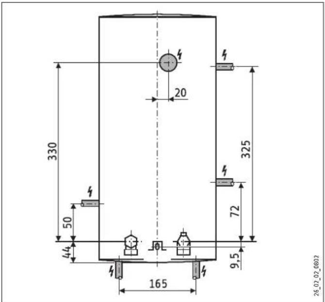
14.1 Dimensioned drawing
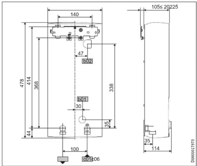
| b01 | Entry electrical cables | ||
| b02 | Entry electrical cables 1 | ||
| c01 | Cold water inlet | male thread | G 1/2 A |
| c06 | DHW outlet | male thread | G 1/2 A |
14.2 Wiring diagram
3/PE \~ 380 - 415 V
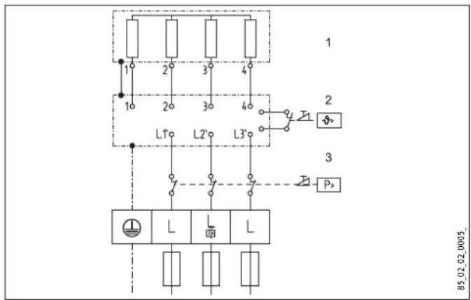
1 Heater
2 High limit safety cut-out
3 Safety pressure limiter
14.3 Mixed water volume / outlet volume
Available temperature approx. 38^ C in the shower, for hand washing, filling the bath etc.
Mixed water volume
| Appliance | kW | 11 | 18 | 21 | 24 | 27 | |
| Cold water inlet temperature | 6 °C | l/min | 5.0 | 8.0 | 9.4 | 10.7 | 12.1 |
| 10 °C | l/min | 5.7 | 9.2 | 10.7 | 12.3 | 13.8 | |
| 14 °C | l/min | 6.6 | 10.7 | 12.5 | 14.5 | 16.1 |
Outlet temperature approx. 60 °C for the kitchen sink and when using thermostatic valves.
Outlet volume
| Appliance | kW | 11 | 18 | 21 | 24 | 27 | |
| Cold water inlet temperature | 6 °C | l/min | 2.9 | 4.8 | 5.6 | 6.4 | 7.2 |
| 10 °C | l/min | 3.2 | 5.2 | 6.0 | 6.9 | 7.7 | |
| 14 °C | l/min | 3.4 | 5.6 | 6.5 | 7.5 | 8.4 |
The values in the table are relative to a rated voltage of 400 V. The outlet volume is subject to the available supply pressure and the available mains voltage.
14.4 Application areas
Specific electrical resistance and specific electrical conductivity
Cold water inlet temperature ≤ 25°C
| Standard value at 15 °C | at 20 °C | at 25 °C | |||||
| Resistance | cm | ≥ 900 | ≥ 1000 | ≥ 800 | ≥ 890 | ≥ 735 | ≥ 815 |
| Conductivity | mS/m | ≤ 111 | ≤ 100 | ≤ 125 | ≤ 112 | ≤ 136 | ≤ 123 |
| Conductivity | s/cm | ≤ 1110 | ≤ 1000 | ≤ 1250 | ≤ 1120 | ≤ 1360 | ≤ 1230 |
Preheated water > 25 °C
| Standard valueat 15 °C | at 20 °C | at 25 °C | |||||
| Resistance | cm | ≥ 1200 | ≥ 1300 | ≥ 1070 | ≥ 1175 | ≥ 985 | ≥ 1072 |
| Conductivity | mS/m | ≤ 83 | ≤ 77 | ≤ 94 | ≤ 85 | ≤ 101 | ≤ 93 |
| Conductivity | s/cm | ≤ 830 | ≤ 770 | ≤ 940 | ≤ 850 | ≤ 1010 | ≤ 930 |
14.5 Pressure drop
14.5.1 Taps/valves
| Pressure drop at flow rate 10 L/min | ||
| Mono-lever mixer tap, approx. | MPa | 0.04 - 0.08 |
| Thermostatic valve, approx. | MPa | 0.03 - 0.05 |
| Hand shower, approx. MPa | 0.03 - 0.15 | |
14.5.2 Sizing the pipework
When calculating the size of the pipework, a pressure drop for the appliance of 0.1 MPa is recommended.
14.6 Fault conditions
In case of faults, loads up to a maximum of 95^ C at a pressure of 1.2 MPa can occur temporarily in the installation.
14.7 Country-specific approvals and certifications
Test symbols can be seen on the type plate.
14.7.1 Notice for Australia / New Zealand:
The installation shall comply with AS/NZS 3500.4.
14.8 Specification
| DHB-E 11 SLi DHB-E 13 SLi DHB-E 13 A DHB-E 18 SLi 25A DHB-E 18/21/24 SLi DHB-E 27 SLi | |||||||
| 232013 | 232014 | 232360 | 232015 | 232016 | 232017 | ||
| Electrical details | |||||||
| Rated voltage 1 | V | 380 | 380 | 380 | 380 | 380 | 380 |
| Rated output 1 | kW | 10.1 | 12.2 | 16.2 | 16.2/19/21.7 | 24.4 | |
| Rated current 1 | A | 15.4 | 18.5 | 24.7 | 27.6/29.5/33.3 | 37.1 | |
| Fuse 1 | A | 16 | 20 | 25 | 32/32/35 | 40 | |
| Rated voltage 2 | V | 400 | 400 | 400 | 400 | 400 | 400 |
| Rated output 2 | kW | 11 | 13.5 | 18 | 18/21/24 | 27 | |
| Rated current 2 | A | 16 | 19.5 | 26 | 29/31/35 | 39 | |
| Fuse 2 | A | 16 | 20 | 25 | 32/32/35 | 40 | |
| Rated voltage 3 | V | 415 | 415 | 415 | 415 | 415 | 415 |
| Rated output 3 | kW | 14.5 | |||||
| Rated current 3 | A | 20.2 | |||||
| Fuse 3 | A | 20 | |||||
| Phases | 3/PE | 3/PE | 3/PE | 3/PE | 3/PE | 3/PE | |
| Frequency | Hz | 50/60 | 50/60 | 50 | 50/60 | 50/60 | 50/- |
| Max. mains impedance Zmax to DIN EN 61000-3-11 | Ohm | 0.45 | 0.43 | 0.45 | 0.33 | 0.3 | |
| Specific resistance (≤25 °C) | Ohm cm | 900 | 900 | 1000 | 900 | 900 | 900 |
| Specific resistance (>25 °C) | Ohm cm | 1200 | 1200 | 1300 | 1200 | 1200 | 1200 |
| Connections | |||||||
| Water connection | G 1/2 A | G 1/2 A | G 1/2 A | G 1/2 A | G 1/2 A | G 1/2 A | |
| Application limits | |||||||
| Max. permissible pressure | MPa | 1 | 1 | 1 | 1 | 1 | 1 |
| Max. inlet temperature for reheating | °C | 45 | 45 | 45 | 45 | 45 | 45 |
| Values | |||||||
| Max. permissible inlet temperature | °C | 60 | 60 | 60 | 60 | 60 | 60 |
| ON | l/min | >3.0 | >3.0 | >3.0 | >3.0 | >3.0 | >3.0 |
| Flow rate for pressure drop | l/min | 3.1 | 3.9 | 3.9 | 5.2 | 5.2/6.0/6.9 | 7.7 |
| Pressure drop at flow rate | MPa | 0.07 (0.02 without flow rate limit) | 0.11 (0.03 without flow rate limit) | 0.11 (0.03 without flow rate limit) | 0.08 (0.06 without flow rate limit) | 0.08/0.10/0.13 (0.06/0.08/0.10 without flow rate limit) | 0.16 (0.12 without flow rate limit) |
| Flow rate limit at | l/min | 4.0 | 4.0 | 4.0 | 7.5 | 7.5/7.5/8.5 | 8.5 |
| DHW delivery | l/min | 5.6 | 6.9 | 6.9 | 9.2 | 9.2/10.7/12.3 | 13.8 |
| Delta T if presented | K | 28 | 28 | 28 | 28 | 28 | 28 |
| Hydraulic data | |||||||
| Rated capacity | I | 0.4 | 0.4 | 0.4 | 0.4 | 0.4 | 0.4 |
| Versions | |||||||
| Connected load options | - | - | - | - | X | - | |
| Temperature adjustment | °C | 30 - 60 | 30 - 60 | 30-50 | 30 - 60 | 30 - 60 | 30 - 60 |
| Protection class | 1 | 1 | 1 | 1 | 1 | 1 | |
| Insulation block | Plastic | Plastic | Plastic | Plastic | Plastic | Plastic | |
| Heating system | Bare wire | Bare wire | Bare wire | Bare wire | Bare wire | Bare wire | |
| Cap and back panel | Plastic | Plastic | Plastic | Plastic | Plastic | Plastic | |
| Colour | white | white | white | white | white | white | |
| IP-Rating | IP25 | IP25 | IP25 | IP25 | IP25 | ||
| Dimensions | |||||||
| Height | mm | 478 | 478 | 478 | 478 | 478 | 478 |
| Width | mm | 225 | 225 | 225 | 225 | 225 | 225 |
| Depth | mm | 105 | 105 | 105 | 105 | 105 | 105 |
| Weights | |||||||
| Weight | kg | 3.6 | 3.6 | 3.6 | 3.6 | 3.6 | 3.6 |
Warranty
The warranty conditions of our German companies do not apply to appliances acquired outside of Germany. In countries where our subsidiaries sell our products, it is increasingly the case that warranties can only be issued by those subsidiaries. Such warranties are only granted if the subsidiary has issued its own terms of warranty. No other warranty will be granted.
We shall not provide any warranty for appliances acquired in countries where we have no subsidiary to sell our products. This will not affect warranties issued by any importers.
Environment and recycling
We would ask you to help protect the environment. After use, dispose of the various materials in accordance with national regulations.
NOTES
Deutschland
Urzhumskaya street 4,
building 2 | 129343 Moscow
Tel. 0495 7753889 | Fax 0495 7753887
info@stiebel-eltron.ru
www.stiebel-eltron.ru
Slovakia
TATRAMAT - ohrievače vody, s.r.o.
Hlavná 1 | 058 01 Poprad
Tel. 052 7127-125 | Fax 052 7127-148
info@stiebel-eltron.sk
www.stiebel-eltron.sk
Switzerland
STIEBEL ELTRON AG
United Kingdom and Ireland
STIEBEL ELTRON UK Ltd.
Unit 12 Stadium Court
Stadium Road | CH62 3RP Bromborough
Tel. 0151 346-2300 | Fax 0151 334-2913
info@stiebel-eltron.co.uk
www.stiebel-eltron.co.uk
United States of America
STIEBEL ELTRON, Inc.
17 West Street | 01088 West Hatfield MA
Tel. 0413 247-3380 | Fax 0413 247-3369
info@stiebel-eltron-usa.com
www.stiebel-eltron-usa.com

Irrtum und technische Änderungen vorbehalten! | Subject to errors and technical changes! | Sous réserve d'erreurs et de modifications techniques! | Onder voorbehoud van vergissingen en technische wijzigingen! | Salvo error o modificación técnica! | Excepto erro ou alteração técnica | Zastrzeżone zmiany techniczne i ewentualne błędy | Omyly a technické zmény jsou vyhrazeny! | A muszaki változtatások és tévedések jogát fenntartjuk! | Отсутствие ошибok ne гарантируется. Возможны технические изменения. | Chyby a technické zmeny sú vyhradenél Stand 8753
STIEBEL ELTRON
- OPERATING AND INSTALLATION
- INSTALLATION
- OPERATION
- General information
- Note
- Safety instructions
- Structure of safety instructions
- KEYWORD Type of risk
- Symbols, type of risk
- Keywords
- Other symbols in this documentation
- Units of measurement
- Safety
- Correct use
- Safety instructions
- CAUTION Burns
- WARNING Injury
- Material damage
- CE designation
- Appliance description
- Operation
- Temperature selector
- Draw-off capacities
- Thermostatic valve
- Temperature limit/Anti-scalding protection
- Cleaning, care and maintenance
- Troubleshooting
- Safety
- General safety instructions
- Instructions, standards and regulations
- WARNING Risk of electrocution
- Water installation
- Cold water line
- DHW line
- Risk of frost
- Appliance description
- Standard delivery
- Installation
- Temperature limiting/anti-scalding protection
- Installation versions
- Accessories
- Taps
- Plug G 12 A
- Installation sets for installation on finished walls
- Universal mounting frame
- Pipe set for undersink appliances
- Pipe set, offset installation
- Pipe set for replacing a gas water heater
- DHB replacement pipe set
- Load shedding relay LR 1-A
- ZTA 3/4 - Central thermostatic valve
- Installation
- Installation information
- Flow pressure
- Flexible water connection lines
- Appliance with changeover connected load
- Installation
- Installation location
- Fitting the mounting bracket
- Preparing the water connection
- Fitting the sieve
- Installing the DMB flow limiter
- Mounting the appliance
- Finalising the water connection
- Connecting the power supply
- Fitting the lower back panel
- Completing the installation process
- Installation versions
- Power supply from above for unfinished walls
- Power supply for finished walls
- Power supply for large cross-sections
- Connecting a load shedding relay
- Water installation for finished walls
- Water installation for finished walls with solder/compression fitting
- Water installation for finished walls, fitting the appliance cap
- Installing lower part of back panel
- Installation in case of appliance replacement
- Undersink installation with turned appliance cap
- Installation for offset tiles
- Commissioning
- Appliance handover
- Troubleshooting
- Display options LED diagnostic "traffic lights"
- Fault table
- Specification
- Mixed water volume / outlet volume
- Application areas
- Pressure drop
- Sizing the pipework
- Fault conditions
- Country-specific approvals and certifications
- Notice for Australia / New Zealand:
- Warranty
- Environment and recycling
- Deutschland
- Slovakia
- Switzerland
- United Kingdom and Ireland
- United States of America
- STIEBEL ELTRON
Brand : STIEBEL ELTRON
Model : DHB-E 13 A
Category : Uncategorized