
RM-2 - Uncategorized FOSTEX - Free user manual and instructions
Find the device manual for free RM-2 FOSTEX in PDF.

| Product Type | Rack-mountable Powered Monitor System |
| Model | RM-2 |
| Speaker Type | 110 x 40 mm cone, magnetically shielded x 2 |
| Impedance | 8 ohms |
| Output Sound Pressure Level | 84 dB/W (1m) |
| Frequency Response | 200 Hz to 20 kHz |
| Rated Output Power | 10 W or more (8 ohms, 1 kHz) |
| Residual Noise | -60 dBV or less (DIN AUDIO) |
| Distortion | 0.5 % or less (10 W/4 ohms, 1 kHz) |
| Digital Input Connector | XLR-3-31 (AES/EBU, 44.1-96 kHz) |
| Analog Input Connector | XLR/1/4" combi-jack (+4 dBu XLR, -10 dBV 1/4") |
| Headphones Output | 1/4" stereo jack, 20 mW + 20 mW (32 ohms) |
| Level Meter | 26-dot LED x 2, peak (digital) or VU (analog) |
| Mute Functions | User mute (manual) and system mute (automatic) |
| Channel Selection | Stereo, Mono (L+R), Mono (L only), Mono (R only) |
| Power Requirement | 120 VAC 60 Hz (US) or 230-240 VAC 50/60 Hz (EU) |
| Power Consumption | 10 W |
| External Dimensions | 430 (W) x 44 (H) x 260 (D) mm |
| Weight | Approximately 3.5 kg |
| Supplied Accessories | Power cord, Owner's manual, Rack mount adaptors x 2, Rubber feet x 4 |
| Safety | Do not expose to rain/moisture; unplug during storms; refer servicing to qualified personnel |
| Cleaning | Clean with dry cloth only |
Frequently Asked Questions - RM-2 FOSTEX
User questions about RM-2 FOSTEX
0 question about this device. Answer the ones you know or ask your own.
Ask a new question about this device
Download the instructions for your Uncategorized in PDF format for free! Find your manual RM-2 - FOSTEX and take your electronic device back in hand. On this page are published all the documents necessary for the use of your device. RM-2 by FOSTEX.
USER MANUAL RM-2 FOSTEX
(DIGITAL I/O VERSION)
Model RM-2

Introduction
Thank you very much for purchasing the Fostex Model RM-2.
The Model RM-2 is a rack-mountable powered monitor system which allows you to monitor digital or analog audio signals.
It incorporates a 10 W x 2 power amplifier and outputs signals from the internal speakers (or from the headphones output jack). You can check the input level via the 26-dot LED meters.
Read this owner's manual thoroughly before using. We hope you will use the RM-2 for a long time.
Table of contents
Safety instruction....2
Names and functions ....4
After turning on the power 4
Indication of channel selection ....6
"System mute" and "user mute"....6
Main specifications ....7

CAUTION
RISK OF ELECTRIC SHOCK DO NOT OPEN

CAUTION: TO REDUCE THE RISK OF ELECTRIC SHOCK, DO NOT REMOVE COVER (OR BACK).
NO USER - SERVICEABLE PARTS INSIDE.
REFER SERVICING TO QUALIFIED SERVICE PERSONNEL.
"WARNING"
"TO REDUCE THE RISK OF FIRE OR ELECTRIC SHOCK, DO NOT EXPOSE THIS APPLIANCE TO RAIN OR MOISTURE."
SAFETY INSTRUCTIONS
- Read Instructions - All the safety and operating instructions should be read before the appliance is operated.
- Retain Instructions - The safety and operating instructions should be retained for future reference.
- Heed Warnings - All warnings on the appliance and in the operating instructions should be adhered to.
- Follow Instructions - All operating and use instructions should be followed.
- Water and Moisture - The appliance should not be used near water - for example, near a bathtub, washbowl, kitchen sink, laundry tub, in a wet basement, or near a swimming pool, and the like.
- Carts and Stands - The appliance should be used only with a cart or stand that is recommended by the manufacturer.

An appliance and cart combination should be moved with care. Quick stops, excessive force, and uneven surfaces may cause the appliance and cart combination to overturn.
- Wall or Ceiling Mounting - The appliance should be mounted to a wall or ceiling only as recommended by the manufacturer.
- Ventilation - The appliance should be situated so that its location or position dose not interfere with its proper ventilation. For example, the appliance should not be situated on a bed, sofa, rug, or similar surface that may block the ventilation openings; or, placed in a built-in installation, such as a bookcase or cabinet that may impede the flow of air through the ventilation openings.
- Heat - The appliance should be situated away from heat sources such as radiators, heat registers, stoves, or other appliances (including amplifiers) that produce heat.
- Power Sources - The appliance should be connected to a power supply only of the type described in the operating instructions or as marked on the appliance.
- Grounding or Polarization - The precautions that should be taken so that the grounding or polarization means of an appliance is not defeated.
CAUTION:
TO PREVENT ELECTRIC SHOCK, MATCH WIDE BLADE OF PLUG TO WIDE SLOT, FULLY INSERT.
ATTENTION:
POUR ÉVITER LES CHOCS ÉLECTRIQUES, INTRODUIRE LA LAME LA PLUS LARGE DE LA FICHE DANS LA BORNE CORRESPONDANTE DE LA PRISE ET POUSSER JUSQU' AU FOND.

The lightning flash with arrowhead symbol, within an equilateral triangle, is intended to alert the user to the presence of uninsulated "dangerous voltage" within the product's enclosure that may be of sufficient magnitude to constitute a risk of electric shock to persons.

The exclamation point within an equilateral triangle is intended to alert the user to the presence of important operating and maintenance (servicing) instructions in the literature accompanying the appliance.
- Power Cord Protection - Power supply cords should be routed so that they are not likely to be walked on or pinched by items placed upon or against them, paying particular attention to cords at plugs, convenience receptacles, and the point where they exit from the appliance.
- Cleaning - The appliance should be cleaned only as recommended by the manufacturer.
- Nonuse Periods - The power cord of the appliance should be unplugged from the outlet when left unused for a long period of time.
- Object and Liquid Entry - Care should be taken so that objects do not fall and liquids are not spilled into the enclosure through openings.
- Damage Requiring Service - The appliance should be serviced by qualified service personnel when:
A. The power supply cord or the plug has been damaged; or
B. Objects have fallen, or liquid has been spilled into the appliance; or
C. The appliance has been exposed to rain; or
D. The appliance does not appear to operate normally or exhibits a marked change in performance; or
E. The appliance has been dropped, or the enclosure damaged. - Servicing - The user should not attempt to service the appliance beyond that described in the operating instructions. All other servicing should be referred to qualified service personnel.
- The appliance should be situated away from drops of water or spray of water.
- Objects containing liquid such as vase must not be put on the appliance.
- The appliance is not completely isolated from the power supply even if the power switch is at off position.
- Apparatus shall not be exposed to dripping or splashing and no objects filled with liquids, such as vases, shall be placed on the apparatus.
- Only use attachments/accessories specified by the manufacturer.
- An appliance with a protective earth terminal should be connected to a mains outlet with a protective earth connection.
- An appliance should be placed in a position where an AC plug / inlet can be easily pulled out by hand.
- Main plug is used as the disconnection device. It shall remain readily operable and should not be obstructed during intended use. To be completely disconnected the apparatus from supply mains, the mains plug of the apparatus shall be disconnected from the mains socket outlet completely.
Important Safety Instructions
1) Read these instructions.
2) Keep these instructions.
3) Heed all warnings.
4) Follow all instructions.
5) Do not use this apparatus near water.
6) Clean only with dry cloth.
7) Do not block any ventilation openings. Install in accordance with the manufacturer's instructions.
8) Do not install near any heat sources such as radiators, heat registers, stoves, or other apparatus (including amplifiers) that produce heat.
9) Do not defeat the safety purpose of the polarized or grounding-type plug.
A polarized plug has two blades with one wider than the other. A grounding type plug has two blades and a third grounding prong. The wide blade or the third prong are provided for your safety.
If the provided plug does not fit into your outlet, consult an electrician for replacement of the obsolete outlet.
10) Protect the power cord from being walked on or pinched particularly at plugs, convenience receptacles, and the point where they exit from the apparatus.
11) Only use attachments/accessories specified by the manufacturer.
12) Use only with the cart, stand, tripod, bracket, or table specified by the manufacturer, or sold with the apparatus. When a cart is used, use caution when moving the cart/apparatus combination to avoid injury from tip-over.

13) Unplug this apparatus during lightning storms or when unused for long periods of time.
14) Refer all servicing to qualified service personnel. Servicing is required when the apparatus has been damaged in any way, such as power-supply cord or plug is damaged, liquid has been spilled or objects have fallen into the apparatus, the apparatus has been exposed to rain or moisture, does not operate normally, or has been dropped.
Names and functions
After turning on the power
Each time you turn on the power, the RM-2 is muted and the "MUTE" indicator flashes. (Figure 1 below shows the condition of the status information section when you first turn on the power after purchasing the RM-2.)
To use the RM-2, therefore, press the [CH SEL] key to unmute the RM-2 (see Figure 2 below).
The "MUTE" indicator turns off. In particular conditions, the system mute function works and the RM-2 is automatically muted, while you can manually mute it whenever you want. See page 6 for details.
![Figure 1 MONO L MUTE R DIGITAL Lighting Flashing Lighting Figure 2 RM-2 STUDIO PACK MONITOR FOSTEX PHONES L MIN MAX CH SEL INPUT ONALOG DIGITAL Press the [CH SEL] key.](/content/2026/05/789369/images/56c487bca9b6330acacd06967eeb0bc560a01a98ed9f57b3f9f9664ab27fadea.jpg)
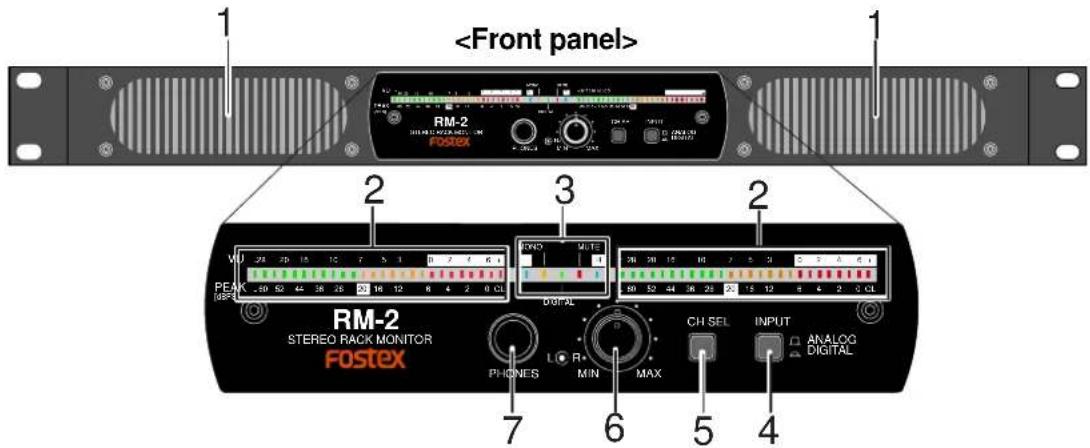
1) Internal speakers
2) LED level meters
These meters show the input levels of digital or analog input signals.
| When the [INPUT] switch is set to DIGITAL | The levels of digital input signals are shown by peak metering. The peak value is hold for three seconds. |
| When the [INPUT] switch is set to ANALOG | The levels of analog input signals are shown by VU metering. The peak value is hold. |
| When digital input is selected: Peak metering, 0 dB: 0dBFS When analog input is selected: VU metering, 0dB: +4 dBu/-10 dBV | |
3) Status information section
This section indicates the status of the [CH SEL] key and [INPUT] switch, as well as mute on/off status. See page 6 for details.
4) [INPUT] (input select) switch
This switch selects the input signal between analog and digital.
| ANALOG(□) | You can monitor the analog signals received via the [ANALOG INPUT] connectors. |
| DIGITAL(□) | You can monitor the digital signal received via the [DIGITAL INPUT] connectors. When the unit receives a correct digital signal and works correctly, the "DIGITAL" indicator in the status information section lights. When the unit does not receive a correct digital signal or does not work correctly, the "DIGITAL" indicator flashes. |
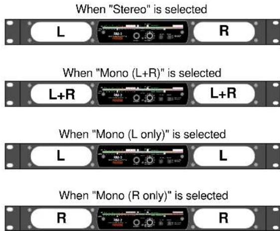
5) [CH SEL] (channel select) key
This key switches the channel(s) to be monitored.
Each press of the key switches the channel(s) in the following order (by default when turning on the power, "stereo" is selected).
The current selection is shown by the indicators in the status information section (see page 6 for the indication of channel selection).
![FOSTEX RM-2 - 5) [CH SEL] (channel select) key - 1](/content/2026/05/789369/images/65b90174d4ebe705a7fc0aa59e0d757f17f2fb8d349868aba08d47f28a47445b.jpg)
flowchart
graph TD
    A["Stereo"] --> B["Mono (L+R)"]
    B --> C["Mono (L only)"]
    C --> D["Mono (R only)"]
    D --> A
By long press of the [CH SEL] key, you can mute the unit, while the [MUTE] indicator flashes (this is called "user mute"). Pressing the [CH SEL] key again release muting and the [MUTE] indicator turns off. See page 6 for the user mute function.
The following shows which signal is output from each internal speaker unit for each channel selection.
6) Monitor output level controls
These dual concentric controls adjust the speaker output (or headphones output) levels. The outer control adjusts the left channel level, while the inner control adjusts the right channel level.
7) PHONES jack
This jack is used for connecting headphones. When a plug is inserted, the internal speakers are cut.
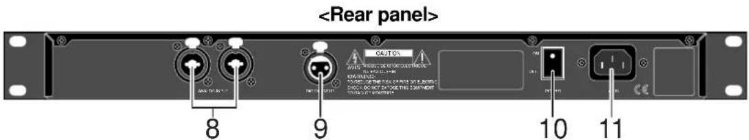
8) [ANALOG INPUT] connectors (XLR / 1/4" combi-jacks)
You can connect an XLR-3-12C connector or 1/4" plug to each of these combi-jack type [ANALOG INPUT] connectors (you cannot insert both together). Each connector accepts a +4 dBu analog signal via XLR connection or a -10 dBV analog signal via 1/4" connection.
![FOSTEX RM-2 - 8) [ANALOG INPUT] connectors (XLR / 1/4" combi-jacks) - 1](/content/2026/05/789369/images/1bbc4ef9b86032e8218af93ce317ae9f5dd7f7acab519330a621e0a7da3fde62.jpg)
| HOT (+) | COLD (-) | Ground | |
| XLR | Pin 2 | Pin 3 | Pin 1 |
9) [DIGITAL INPUT] connector (XLR connector)
This connector accepts an AES/EBU digital signal at the sampling frequency within the 44.1 kHz to 96 kHz range. You can connect an XLR-3-12C connector.
![FOSTEX RM-2 - 9) [DIGITAL INPUT] connector (XLR connector) - 1](/content/2026/05/789369/images/e72c8718e1e3810e461c12138f9f35229eb08e8a7b6bd53eb3334cd617cc55ea.jpg)
| HOT (+) | COLD (-) | Ground | |
| XLR | Pin 2 | Pin 3 | Pin 1 |
10) [POWER] switch
This switch turns the power on or off. Each time you turn on the power, the RM-2 is muted for preventing the noise from being generated from the speaker units (the "MUTE" indicator flashes).
11) [AC IN] connector
Connect to the AC outlet using the supplied power cord. Make sure that the AC outlet voltage matches the unit.
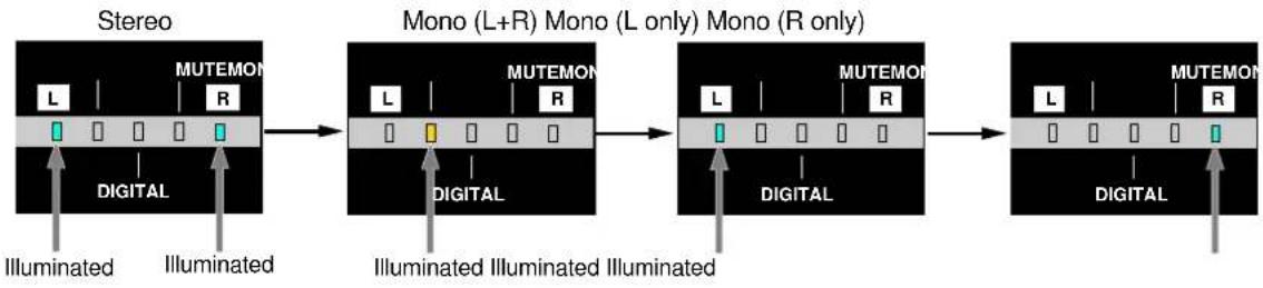
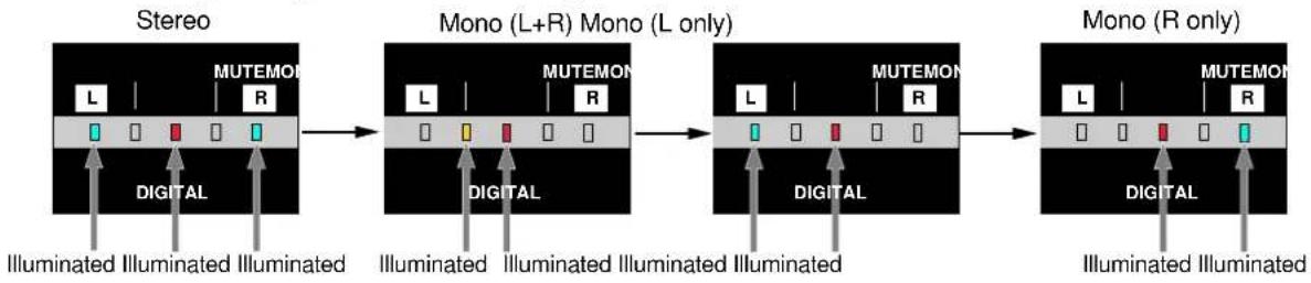
Indication of channel selection
You can see which channel(s) is/are now selected by the [CH SEL] key via the status information section, as below.
- When the [INPUT] switch is set to "Analog"
flowchart
graph LR
    A["Stereo"] --> B["Mono (L+R) Mono (L only) Mono (R only)"]
    B --> C["Mono (L+R) Mono (L only) Mono (R only)"]
    A --> D["Digital"]
    B --> E["Digital"]
    C --> F["Digital"]
    D --> G["Illuminated"]
    E --> H["Illuminated"]
    F --> I["Illuminated"]
    style A fill:#f9f,stroke:#333
    style B fill:#f9f,stroke:#333
    style C fill:#f9f,stroke:#333
    style D fill:#ccf,stroke:#333
    style E fill:#ccf,stroke:#333
    style F fill:#ccf,stroke:#333
- When the [INPUT] switch is set to "Digital"
flowchart
graph LR
    A["Stereo"] --> B["Mono (L+R) Mono (L only)"]
    B --> C["Mono (R only)"]

    subgraph Stereo
        L1["L"] --> M1["MUTEMON R"]
        M1 --> M2["Digital"]
        M2 --> Illuminated1["Illuminated"]
        M2 --> Illuminated2["Illuminated"]
        M2 --> Illuminated3["Illuminated"]
    end

    subgraph Mono (L+R) Mono (L only)
        L3["L"] --> M4["MUTEMON R"]
        M4 --> M5["Digital"]
        M5 --> Illuminated4["Illuminated"]
        M5 --> Illuminated5["Illuminated"]
        M5 --> Illuminated6["Illuminated"]
    end

    subgraph Mono (R only)
        L6["L"] --> M7["MUTEMON R"]
        M7 --> M8["Digital"]
        M8 --> Illuminated7["Illuminated"]
        M8 --> Illuminated8["Illuminated"]
        M8 --> Illuminated9["Illuminated"]
    end
"System mute" and "user mute"
The RM-2 has two mute functions. One is the "user mute" function which allows you to manually mute the unit whenever you want, while the other is the "system mute" function which automatically mute the unit in particular conditions.
User mute: The user mute function allows you to mute the unit manually by pressing and holding down the [CH SEL] key until the [MUTE] indicator lights up (the level meters show the input levels regardless of the mute condition). You can release muting by pressing the [CH SEL] key briefly.
System mute: The RM-2 is automatically muted in any of conditions (1) through (3) below (unlike the user mute, the level meters do not show the input levels in this case). The system mute function is activated to prevent the noise from being generated from the speaker units. In the cases of (1) and (2) below, muting is released after a few seconds. In the case of (3), muting is released when the unit locks to the external digital signal.
(1) When you turn on the power.
(2) When you press the [INPUT] switch to switch the input.
(3) When the unit does not lock to the external digital clock while selecting the digital input.
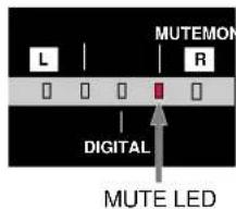
The MUTE indicator shows mute status. When the system mute is active, the MUTE indicator is lit. When the user mute is active, the MUTE indicator flashes. As the user mute status takes priority to the system mute status, the MUTE indicator shows the status as follows.
| System mute | |||
| OFF | ON | ||
| User mute | OFF | Unlit Lit | |
| ON | Flashing | Flashing | |
Main Specifications
- Unit: 110 x 40 mm, cone type, magnetically shielded type x 2
- Impedance: 8 ohms
• Output sound pressure level: 84 dB/W (1m)
• Frequency response: 200 Hz to 20 kHz
- Rated output power: 10 W or more (8 ohms, 1 kHz)
- Residual noise: -60 dBV or less (DIN AUDIO)
• Distortion: 0.5 % or less (10 W/4ohms, 1 kHz) - Digital input
Connector: XLR-3-31 type
Format: IEC 60958 (AES/EBU)
Sampling frequency: 44.1 kHz to 96 kHz
- Analog input
Connector: XLR/ 1/4 combi-jack
Nominal input level: +4 dBu (XLR), -10 dBV (1/4")
Input impedance: 10 kohms or more
- PHONES
Connector: 1/4-inch stereo jack
Applicable load impedance: 8 ohms or more
Rated output power: 20 mW + 20 mW (32 ohms, 1 kHz)
- Level meters:
When digital input is selected:
When analog input is selected:
26-dot LED meter x 2
Peak metering, 0 dB: 0dBFS
VU metering, 0dB: +4 dBu/-10 dBV
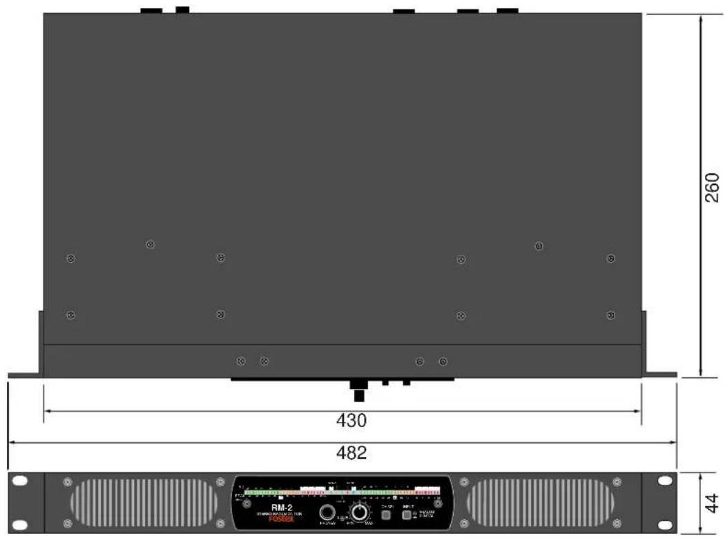
- External dimensions: 430 (W) x 44 (H) x 260 (D) mm
• Weight: Approximately 3.5 kg
• Power requirement: 120VAC 60Hz (for US and CANADA version)
230VAC\~240VAC 50/60Hz (for Europe version)
• Power consumption: 10 W
• Supplied accessories: Power cord, Owner's manual, Rack mount adaptor x 2, Rubber foot x 4
* Specifications and appearance are subject to change without notice for product improvement.


- Model RM-2
- Introduction
- Table of contents
- CAUTION
- "WARNING"
- SAFETY INSTRUCTIONS
- CAUTION:
- ATTENTION:
- Important Safety Instructions
- Names and functions
- After turning on the power
- 1) Internal speakers
- 2) LED level meters
- 3) Status information section
- 4) [INPUT] (input select) switch
- 5) [CH SEL] (channel select) key
- 6) Monitor output level controls
- 7) PHONES jack
- 8) [ANALOG INPUT] connectors (XLR / 1/4" combi-jacks)
- 9) [DIGITAL INPUT] connector (XLR connector)
- 10) [POWER] switch
- 11) [AC IN] connector
- Indication of channel selection
- "System mute" and "user mute"
- Main Specifications
Brand : FOSTEX
Model : RM-2
Category : Uncategorized