TSQ 310 - Uncategorized Fte maximal - Free user manual and instructions
Find the device manual for free TSQ 310 Fte maximal in PDF.


User questions about TSQ 310 Fte maximal
0 question about this device. Answer the ones you know or ask your own.
Ask a new question about this device
Download the instructions for your Uncategorized in PDF format for free! Find your manual TSQ 310 - Fte maximal and take your electronic device back in hand. On this page are published all the documents necessary for the use of your device. TSQ 310 by Fte maximal.
USER MANUAL TSQ 310 Fte maximal
NOTE: This user's guide is adapted to software version 000A/0003 of TSQ 310 dated 18/10/2010.
For future software updates, you can download the user's guide from the following website: http://www.ftemaximal.com/
Chapter 1. Installation.
1.1. Safety Measures
1.- Never place the device next to hot sources.
2.- Never undergo the device to temperatures that exceed its level of operation.
3.- Never expose the device to leakings nor spatterings.
4.- Never place objects that contain liquids over the device.
5.- Respect the ventilation slots of the device, do not cover them with any kind of object.
6.- The space around the device must be free of objects, in a minimum radius of 40cm.
7.- Avoid locations with possibilities of spilling liquids on the inside of the device, and with important changes of temperature.
8.- Never open the device by yourself due to electric risk. In case of problems, go always to qualified technicians
9.- Never, under no circumstances, open the device when connected to the electrical net..
10.- During the handling it is better to disconnect the device from the electrical net.
11.- Obey the electricity security rules during the assembling. Use materials that obey the current law.
12.- The connecting plug must be accessible in a fast and simple way to have a fast disconnection.
13.- Never touch the plug with wet hands. Also, disconnect always the device before handling the connections.
14.- Never put any heavy object over the device, since it could get damaged.
15.- If the device is going to remain some time without use, it is recommendable to disconnect it from the electrical net.
16.- The repairmen and the maintenance of the device must be done by TV and radio specialised technicians.
1.2. Box content
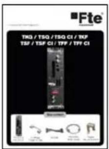
text_image
■Fte TKG / TSQ / TSQ CI / TKF TSP / TSP CI / TFP / TFP CI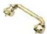
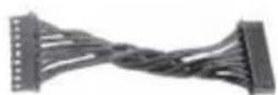
Quick installation guide 2 x Bridge F male - F male DC Cable
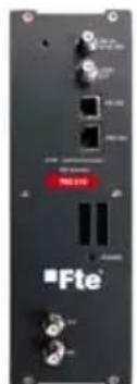
natural_image
Front view of a black electronic device with ports and connectors (no readable text or symbols)
natural_image
Circular mechanical component with two protrusions, no visible text or symbolsTSQ 310 Cable 12 cm PIN to PIN RJ45 - RJ45
1.3. Description and connections
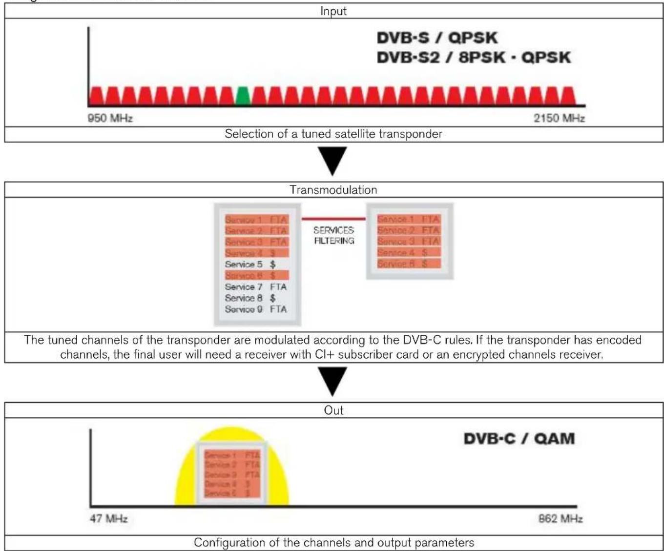
The module TSQ 310 is used for the reception of free channels that obey the DVB-S / DVB-S2 standards. Each module allows the reception of a complete transponder in DVB-S (QPSK) / DVB-S2 (QPSK/8PSK), and the subsequent modulation in DVB-C (QAM) of it.
A feature of this equipment is its modulator in Vestigial Side Band (or VSB). This modulation can be used to distribute adjacent channels in one distribution without any intermodulation problem.
Each module has one Loop connector to cascade several modules at input and a Mix connector to do same in output channels. The output channel is selectable between C2 and C69.
All parameters are programmed by the means of PRO 201 or the EVO or MINI series of field strength meter, and they are monitored in the display of programmer or in the 5" TFT screen of field strength meter.
TSQ 310

text_image
1 LNC IN 13/18 VDC LOOP OUT RS 202 PRO J01 8 TSQ 310 9-PSK - CAM Transmodulator VSB Modulator POWER Fte® maximal 2 OUT 3 MS- Two-colored led*: It indicates the different states of the device.
- OUT: This connector supplies the modulated channel according to the selected standard in the module and mixes it with all the signals that it receives through the MIX connector
- MIX: Input of mixing of the module.
- LNC IN: To connect to the LNC or to the LOOP OUT output of the previous module
- LOOP OUT: To connect to the ANT IN input of the next module.
- RS 232: Ethernet connector to cascade modules with the RCM 310 telecontrol unit with the RJ45/RJ45 cable provided.
- PRO 201: Ethernet connector to make the programming with the programmer.
- DC connectors: It has two connectors for input/output.
\*States of two-colored leds
1. Initialization mode
- Green: main application charged.
- Blinking Green: Completing the initial sequence, at the moment when the module gets initialized, the led will turn into one of the states the operating mode.
- Red: Phase of initializing the module.
2. Operative Mode
- Green: The system is working properly.
- Orange: At least one critical event has been recorded in the module. The led will only change into green when the registration of events has been read by the programmer.
- Red: Error or alert detected in the running of the device, the led will be on only as long as the error/alert is present. Once the error or the alert disappears, the led will change into orange because the error/alert is stored in the registration of events.
3. Programming mode
- When the module detects an external programmer, the led will blink in the next sequence: green-orange-red.
- Once you leave the programming mode, the led will turn into the corresponding operating mode.
Stages of transmodulator TSQ 310
flowchart
graph TD
    A["Input"] --> B["Selection of a tuned satellite transponder"]
    B --> C["Transmodulation"]
    C --> D["Out"]
    D --> E["Configuration of the channels and output parameters"]

    subgraph Input
        F["DVB·S / QPSK\nDVB·S2 / 8PSK · QPSK"] --> G["950 MHz"]
        G --> H["2150 MHz"]
    end

    subgraph Transmodulation
        I["Service 1 FTA\nService 2 FTA\nService 3 FTA\nService 4 $"]
        J["Service 5 $"]
        K["Service 6 $"]
        L["Service 7 FTA\nService 8 $"]
        M["Service 9 FTA"]
        N["SERVICES FILTERING"]
        O["Service 1 FTA\nService 2 FTA\nService 3 FTA\nService 4 $"]
        P["Service 6 $"]
    end

    subgraph Output
        Q["DVB·C / QAM"] --> R["47 MHz"]
        S["862 MHz"]
    end

    style A fill:#f9f,stroke:#333
    style B fill:#ccf,stroke:#333
    style C fill:#cfc,stroke:#333
    style D fill:#fcc,stroke:#333
    style E fill:#ffc,stroke:#333
    style F fill:#fff,stroke:#333
    style G fill:#fff,stroke:#333
    style H fill:#fff,stroke:#333
    style I fill:#fff,stroke:#333
    style J fill:#fff,stroke:#333
    style K fill:#fff,stroke:#333
    style L fill:#fff,stroke:#333
    style M fill:#fff,stroke:#333
    style N fill:#fff,stroke:#333
    style O fill:#fff,stroke:#333
    style P fill:#fff,stroke:#333
    style Q fill:#fff,stroke:#333
    style R fill:#fff,stroke:#333
    style S fill:#fff,stroke:#333
    style T fill:#fff,stroke:#333
    style U fill:#fff,stroke:#333
    style V fill:#fff,stroke:#333
    style W fill:#fff,stroke:#333
    style X fill:#fff,stroke:#333
    style Y fill:#fff,stroke:#333
1.4. Programming
TSQ 310 has two ethernet connectors. In order to make the programming of the module you have to connect the corresponding programmer to PRO 201 connector.
You can make the programming through the PRO 201 programmer and also through the mediaMAX EVO and mediaMAX MINI field strength meter.
1.4.1. Programming modes
| With mediaMAX EVO / mediaMAX MINI field strength meter you can carry out the programming of all the modules consecutively as long as they are interconnected with each other through the RJ-45 cable supplied with each unit. | Through PRO 201, the programming is made module by module. |
1.4.2. Programming
Below you will find the steps to follow in order to make the programming both from corresponding EVO and MINI field strength meter as well as from PRO 201.
mediaMAX EVO / mediaMAX MINI
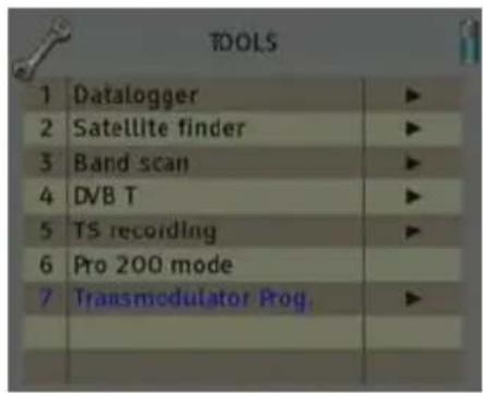
In order to start programming the TSQ 310 transmodulator, you will have to go to "Tools" option through the key 8 of your field strength meter and to select the "Prog Transmodulators" option.
text_image
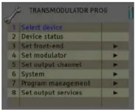
TOOLS 1 Datalogger ▶ 2 Satellite finder ▶ 3 Band scan ▶ 4 DVB T ▶ 5 TS recording ▶ 6 Pro 200 mode 7 Transmodulator Prog ▶ _______________________________Then, it will proceed to recognize the module and to show the main menu. In the "Prog. Transmodulators" are shown the different configuration options that this tool offers:
text_image
TRANSMODULATOR PROG 1 Select device 2 Device status 3 Set front-end ▶ 4 Set modulator ▶ 5 Set output channel ▶ 6 System ▶ 7 Program management ▶ 8 Set output services ▶1. Module selection
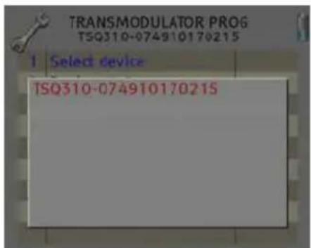
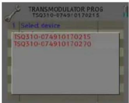
The field strength meter allows carrying out the programming of one or several transmodulators from an only transmodulator.
text_image
TRANSMODULATOR PRO6 TSQ310-074910170215 I Select device TSQ310-074910170215Without interconnection of modules. An only module connected
text_image
TRANSMODULATOR PROG TSQ310-074910170215 1 Select device TSQ310-074910170215 TSQ310-074910170270Interconnection of several modules, you can select which modules you wish to program.
2. State of the module
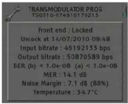
In the option "State of the module" are specified the main parameters of the module at this moment.
- Transmodulator input: It indicates whether the module is hooked or without signal.
- Input bit rate: Transfers of data in the satellite tuner input.
- Output bit rate: Transfer of data in the module output.
- BER before and after Viterbi: It indicates the error rate of bits of the input signal before and after the correction produced by Viterbi algorithm.
- MER: Parameter that indicates the quality of the input modulated digital signal, expressed in dB.
- Noise Margin: It indicates the difference between the value of current C/N and the value of C/N at the point of pixilation of the signal, that is, the quantity of dBs of C/N measure that are needed to lose the input signal.
-Temperature: It indicates the current temperature of the module in °C.
text_image
TRANSMODULATOR PROG TSQ310-074910170215 Front end : Locked Unlock at 14/07/2010 09:48 Input bitrate : 49192133 bps Output bitrate : 50870589 bps BER (b) < 1.0e-08 (a) < 1.0e-08 MER : 14.1 dB Noise Margin : 7.1 dB (88%) Temperature : 34.7°C3. Input configuration
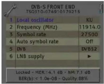
In this option you will be able to configure the input parameters of the satellite signal:
- Local oscillator: Selection of the local oscillator that you wish to use: FI, KU, C, K9750, K10000, K10600, K10700, K10750, K11250, K11300, K11325.
- Frequency (MHz): Transponder frequency that you wish to tune.
- Symbol speed: Symbol speed required by the transponder.
- Auto symbol rate: You will be able to select if the detection of the Symbol Rate is going to be Automatic (On) or Manual (Off).
- Local oscillator: Selection of the local oscillator that you wish to use: FI, KU, C, K9750, K10000, K10600, K10700, K10750, K11250, K11300, K11325. - Frequency (MHz): Transponder frequency that you wish to tune. - Symbol speed: Symbol speed required by the transponder. - Auto symbol rate: You will be able to select if the detection of the Symbol Rate is going to be Automatic (On) or Manual (Off).
- In Manual mode (Off), the value of the Symbol Rate should be fixed by the user based on the provider's information.
- In Automatic mode (On), the meter will automatically identify the SR when a Satellite carrier is tuned. This feature is very useful when the provider's information is unknown.
- In Manual mode (Off), the value of the Symbol Rate should be fixed by the user based on the provider's information. - In Automatic mode (On), the meter will automatically identify the SR when a Satellite carrier is tuned. This feature is very useful when the provider's information is unknown.
text_image
DNB-S FRONT END TSQ310-074910170215 1 Local oscillator KU 2 Frequency (MHz) 11914.0 3 Symbol rate 27500 4 Auto symbol rate Off 5 DVB DVBS2 6 LNB supply ▶ Locked - MER:14.1 dB - NM:7.1 dB BER(b): < 1.0e-08 - Quality:88%The SR value found will appear in the field of selection of the SR menu. This value found by the meter could not correspond exactly to the real broadcast SR, but to a very close value.

Note: The Automatic Symbol Rate feature does not work when the carrier quality is very poor or/and with a very low Power Level.
- DVB: This option allows selecting the standard DVB of the transponder that you want to tune. Options: DVB-S1, DVB-S2 and auto
-
LNB Feeding: In this option you can set the parameters concerning the LNB:
-
Voltage RF IN: 13V, 18V and Off.
- Tone 22 kHz: Off, and Auto. In the
- Switch DiseqC: A, B, C, D and Off.
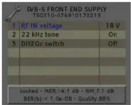
text_image
DVB-S FRONT END SUPPLY TSO310-074910170215 1 RF IN voltage 18 V 2 22 kHz tone On 3 DISFOc switch Off Locked - MER:14.1 dB - NM:7.1 dB BER(b): < 1.0e-08 - Quality:88%4. Modulator configuration
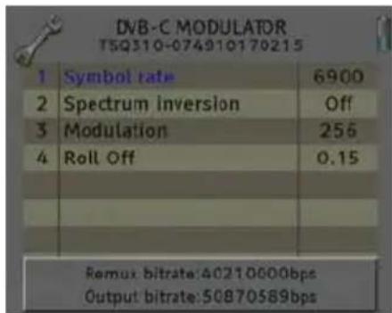
This option allows you to configure the DVB-C modulator that the device has.
- Symbol speed: The available symbol speed ranges from 1 to 6.96 MS/s. In order to estimate the output symbol speed you have to take into account the following parameters: input modulation, input symbol speed, input FEC, output modulation.
For example, for a 8PSK signal with 22000 MS/s and a FEC 2/3, the output symbol speed should be calculated according to the chosen QAM modulation.
text_image
DVB-C MODULATOR T5Q310-074910170215 1 Symbol rate 6900 2 Spectrum inversion Off 3 Modulation 256 4 Roll Off 0.15 Remux bitrate:40210000bps Output bitrate:50870589bps$$ V _ {S Y M B O L. O U T} = \frac {V _ {S Y M B O L . I N}}{\cdot} \quad \cdot \quad \cdot \quad \left(8 P S K s y m b o l n ^ {\circ} b A E C ^ {- 2} / _ {3} ^ {- 3}\right) = \frac {}{(\text { QAMs }) ^ {\text { m b o l n } ^ {\circ} \text { bit }} \text { QAMs m b o l n } ^ {\circ} \text { bit }} $$
| Modulation QPSK | 8PSK 16 | QAM 32 | QAM 64 | QAM 1 | 28 QAM | 256 QAM | ||
| Number of bits per symbol | 2 | 3 | 4 | 5 | 6 | 7 | 8 | |
| Modulation | 16 QAM | 32 QAM | 64 QAM | 128 QAM | 256 QAM |
| Symbol speed (MS/s) | 11000 | 8800 | 7333 | 6286 | 5500 |
- Spectrum inversion: Activate or deactivate the spectrum inversion in the modulation.
- Modulation: Modulation Format. Options: 16 QAM, 32 QAM, 64 QAM, 128 QAM, 256 QAM.
- Roll-off factor: Roll-off factor reduces the interference between symbols thanks to the raised cosine filtering, the bigger this value is, the less interference between symbols that will be caused. Typical Value according to rules DVB-C =15%. Options: 15%,13%.
5. Output configuration
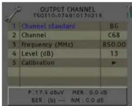
In this option you can configure the different parameters of the cable signal.
- Channel standard: It allows you to select the channelling of the cable signal standards. Options: BG, BG, PAL BG IT, 11, M NTSC, PAL M, PAL N, PAL DK, PAL I, BB_AU, DK PAL, L PAL.
- Channel: Output channel of the cable modulation. When you select the output channel, the field "Frequency (MHz)" will be modified automatically, adapting itself to the selected channel. Options: C2-C69.
- Frequency (MHz): Output frequency of cable modulation. When you modify this field, the field "Channel" will be also modified, indicating the channel equivalent to the selected frequency in the case that this frequency corresponds to the frequency of a channel. Options: 47-862 MHz.
- Level: Regulation of the output level of the modulated signal. Options: 0-15dB.
-
Calibration: Allows the realization of two tests in order to verify the correct running of the device.
-
Output deactivate: It allows activating or deactivating the output of transmodulator.
- Pure carries output: It allows activating or deactivating the DVB-C modulation, allowing visualizing the carrier without modulation in the selected frequency.
text_image
OUTPUT CHANNEL TSQ310-074910176215 1 Channel standard BG 2 Channel C68 3 Frequency (MHz) 850.00 4 Level (dB) 13 5 Calibration ▶ P: 17.6 dBuV MER: 0.0 dB BER: (b) --- NM: 0.0 dB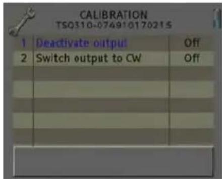
text_image
CALIBRATION TSQ310-074910170215 1 Deactivate output Off 2 Switch output to CW Off _______________________________6. System
This option provides information of the transmodulator.
- System logfile: In this field are indicated the registered events in the module.
- Read log: It allows reading the registered events in the module.
- Clear log: It allows deleting all events stored until this moment.
- Export log to USB: It allows you to export all events registered to the connected USB device.
- NM low Limit (dB): An event of error will be recorded when the value of Noise Margin is lower than the set value.
- NM hight limit (dB): Once the event of error is recorded (Noise Margin < Limit Lower NM), this will be Noise Margin value that will have to be exceed so the module stops being in error.
- Clear log all devices. It allows deleting the events report of all the interconnected modules.
| 1 | System logfile | ▶ |
| 2 | Factory default | |
| 3 | System information | |
| 4 | Settings | ▶ |
| 1 | Read log | |
| 2 | Clear log | |
| 3 | Export log to USB | |
| 4 | NM low limit (dB) | 0.0 |
| 5 | NM high limit (dB) | 3.0 |
| 6 | Clear log all devices | |
- Factory default: This option restores the values by default of the transmodulator.
- System information: It allows you to visualize the basic information of the module: model, no of series, firmware version, etc.
- Settings: This option allows saving and loading the configuration of the module, carrying out firmware update or making an adjustment of the time and date of the module.
- Clock:
- Set Date and time: Setting of the date and time of transmodulator. It is appropriate to maintain these parameters set in order to have the registration of errors linked to the current time and date.
| 1 | Clock | ▶ |
| 2 | Alias | ▶ |
| 3 | Upgrade | ▶ |
| 4 | Configure all devices | |
- Set date/time all devices: Loading the current date and time of the module in the rest of interconnected modules.
- Alias:
- Write alias: It allows you to assign a name/alias to the module you are programming. Option only available when the Alias Auto option is configures as "none" (manual mode).
- Auto Alias: It allows configuring the name/alias of the modules automatically. Options: Channel, Frequency, Service, None.
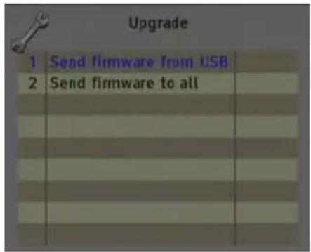
- Upgrade:
- Send Firmware from USB: It allows carrying out the firmware update from the USB device.
- Send firmware to all: It allows carrying out the update of all the modules that are interconnected at the same time.
| 1 | Set date & time | |
| 2 | Set date/time all dev. | |
| 1 | Write alias | |
| 2 | Auto alias | None |
- Configure all devices:
- Input values to all devices: It allows copying the current input configuration in all the interconnected modules.
- Modulator values to all devices: It allows copying the configuration of the current modulator in all the interconnected modules.
- Output values to all devices: It allows copying the current output configuration in all the interconnected modules.
- Factory default to all devices: It allows making values by default to all the interconnected modules.
text_image
Upgrade 1 Send firmware from USB 2 Send firmware to all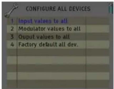
text_image
CONFIGURE ALL DEVICES 1 Input values to all 2 Modulator values to all 3 Output values to all 4 Factory default all dev.7. Program management
- New program: This option allows creating a program with the current configuration of a module or group of modules.
- Load program: It allows loading a previously created program on a module or group of modules.
- Delete program: It allows deleting a program.
- Device to process:
- Current: The creation or loading of a program will be applied only in the module that is currently connected.
- All: The creation or loading of a program will be applied to the whole group of connected modules.
- Working disk: With this option we have the possibility of choosing if we want to work into the internal disk or in the external storage device USB 2.0.
| 1 | New program | |
| 2 | Load program | |
| 3 | Delete program | |
| 4 | Device to process | Current |
| 5 | Working disk | Auto |
| 6 | Load programs from USB | |
| 7 | Save programs to USB | |
| 8 | Write alias | Yes |
Once the option is selected, a dialog box will appear and we will be able to choose among three different options:
- Auto: The Meter decides where the data will be stored. If there is external memory connected, the Meter will store the data in it. If not, it will use the internal memory.
- USB: The Meter always will try to use the external memory connected to the USB port. If this memory has not been connected an error message will be shown, reminding that there was an error storing the data and it will be not stored.
- Internal: Always the internal memory is used to store the data.
- Load programs from USB: This option allows importing programs from a USB memory to the field strength meter. Before using this option you must connect a USB memory.
- Save programs to USB: This option allows copying the programs stored in the external USB 2.0 storage device.
- Write Alias: It allows saving the alias of the module in the program. Options: Yes/No
8. Set Output Services
This option allows making the selection of the services that you wish to include in the output multiplex.
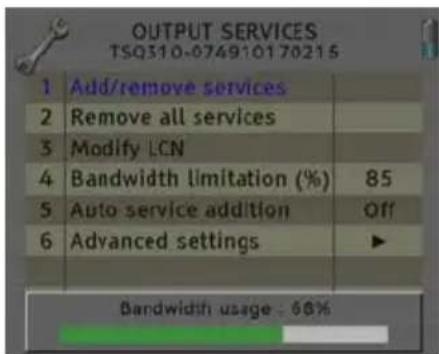
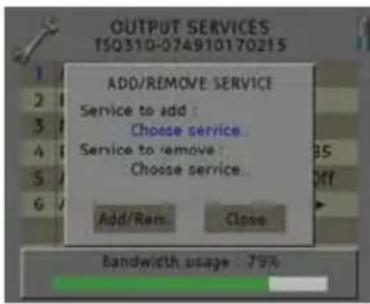
- Add/Remove services: It allows adding the services to the multiplex and also removing the ones previously included. The lower bar informs about the available space in the output multiplex. As you add more services, the space available will decrease.
Once you have tuned a transponder in the "Input Set Up" section and you have selected the DVB-C modulator configuration in the "Modulator Set Up" section, you can make the assignment of the services that are going to be included in the output multiplex "Adding/Removing services".
text_image
OUTPUT SERVICES TSQ310-074910170215 1 Add/remove services 2 Remove all services 3 Modify LCN 4 Bandwidth limitation (%) 85 5 Auto service addition Off 6 Advanced settings ▶ Bandwidth usage: 66%Adding services:
text_image
OUTPUT SERVICES TS0310-074910170215 ADD/REMOVE SERVICE Service to add : Choose service... Service to remove : Choose service... Add/Ram... Close Bandwidth usage: 75%- Select "Service to add" option

text_image
OUTPUT SERVICES TSQ310-074910170215 ADD/REMOVE SERVICE Service to add : 00000 $U Sky Sport HD 00000 $U Sky Cinema HD Bandwidth usage, 58%- Select one of the transponder services you want to add.
text_image
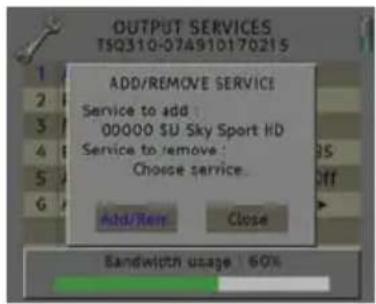
OUTPUT SERVICES TSQ310-074910170215 ADD/REMOVE SERVICE Service to add : 00000 $U Sky Sport HD Service to remove : Choose service... Add/Rem Close Bandwidth usage : 60%- Once you have chosen the service, select the "Add/Remove" button to include the service in the multiplex.

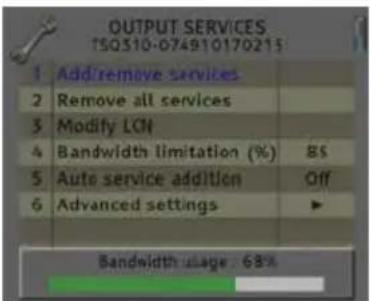
Note: It is not recommended to exceed the 85% of the maximum capacity of the multiplex due to the possible variability of the bits rate of the inputs services.
text_image
OUTPUT SERVICES TSQ310-074910170215 Add/remove services Remove all services Modify LCN Bandwidth limitation (%) 8S Auto service addition Off Advanced settings Bandwidth usage: 68%Recomendad capacity (lower to 85%)
text_image
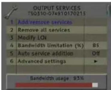
OUTPUT SERVICES TS0310-074910170215 1 Add/remove services 2 Remove all services 3 Modify LGN 4 Bandwidth limitation (%) 85 5 Auto service addition Off 6 Advanced settings ▶ Bandwidth usage 93%Excessive capacity It is recommended to remove services
Removing services:
text_image
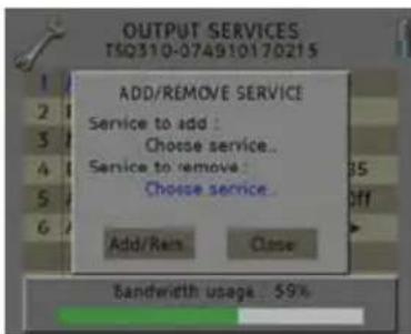
OUTPUT SERVICES TSQ310-074910170215 ADD/REMOVE SERVICE Service to add : Choose service.. Service to remove : Choose service.. Add/Ren Close Bandwidth usage: 59%- Select the "Service to remove" option.
text_image
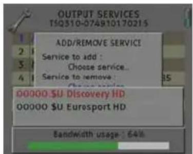
OUTPUT SERVICES TSQ310-07A910170215 ADD/REMOVE SERVICE Service to add : Choose service... Service to remove : 35 00000 $U Discovery HD 00000 $U Euresport HD Bandwidth usage: 64%- Select one of the transponder services you want to remove.
text_image
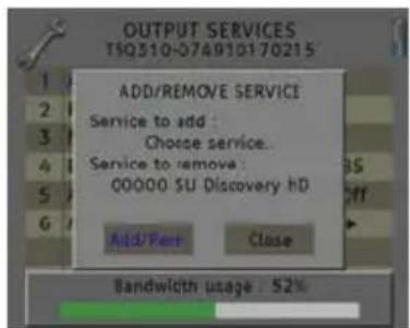
OUTPUT SERVICES TSQ310-074910170215 ADD/REMOVE SERVICE Service to add : Choose service... Service to remove : 00000 SU Discovery hD Add/Pare Close Bandwidth usage : 52%-
Once you have chosen the service, select the "Add/Remove" button to remove the service in the multiplex.
-
Remove all services: It allows removing all the services included in the multiplex.
- Modify LCN: The LNC function allows assigning automatically a predetermined position to each one of the services of the multiplex. This function will allow the users who have a receiver with LNC support to make the ordination of channels automatically.

Note: If in the existing installation there are already services that have LNC system, you will have to configure the position of the module services in order to avoid conflicts with other net services.
- Bandwidth limitation: It allows selecting the % of the capacity of the output channel.
- Auto service addition:
- On: It selects the services automatically when an input carrier is tuned and when the list of selected services is empty. The receiver will have this state by default.
- Always: It selects the services automatically every time a new input carrier is tuned. This state is only recommended to be used for making test in the module.
- Off: The automatic mode is deactivated; the services have to be manually selected.
- Advanced settings:
- Network: It allows making the adjustment of the identification parameters of the multiplex.
- TS ID: Transport Stream identification value. It is recommended to configure a value different from TS ID for each one of the output multiplex configured.
- Net ID: Net identification value
- Original Net ID: Original net identification value
- Network Name: Name associated with the net.

text_image
OUTPUT SERVICES TSQ310-074910170215 MODIFY LCN Service to process : Choose service. New LCN : 0 Modify Close Bandwidth usage : 62%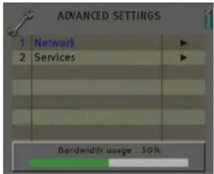
text_image
ADVANCED SETTINGS 1 Network ▶ 2 Services ▶ Bandwidth usage : 50%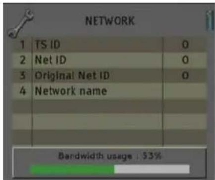
text_image
NETWORK 1 TS ID 0 2 Net ID 0 3 Original Net ID 0 4 Network name Bandwidth usage : 53%- Services:
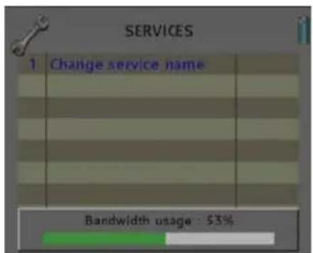
- Change service name: It allows changing the name of the service manually. In order to do so, please choose the service in the first line and then write the new name in the second line. Then you have to press "modify" in order to save the changes.
text_image
SERVICES 1 Change service name Bandwidth usage : 53%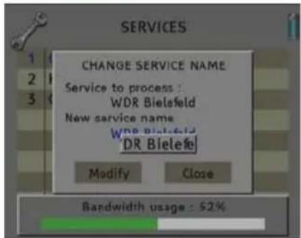
text_image
SERVICES CHANGE SERVICE NAME Service to process : WDR Bielsfeld New service name: WDR Bielsfeld DR Bielefeld Modify Close Bandwidth usage : 52%Next it is attached the identification table (NID/ONID) of the main satellites. You will be able to find more information in the law ETSI TR 101 162 v1.2.1.
| Satellite Net ID Original Net ID Description | |||
| Hotbird 13°E (Eutelsat 13°E) 318 318 Eutelsat 13°E System | |||
| Astra 19.2°E 1 1 Astra Satellite Network 19,2°E | |||
| Astra 23°E 3-25 3-25 Astra n (n=1-23) | |||
| Astra 28,2°E 2 2 Astra Satellite Network 28,2°E | |||
| Nilesat 7°W 2048 | 2048 Nilesat 101 | ||
| Hispasat 30°W | 33 | 33 Hispasat Network 1 | |
PRO 201

Note: From PRO 201 programmer you can only carry out the programming of a single module, in order to carry out the programming of several modules at the same time you have to use a mediaMAX EVO or mediaMAX MINI series field strength meter.
When you connect the PRO 201 programmer, it will proceed to recognize the module and to show the main menu.
In the main menu are shown the different options for configuring the transmodulator.
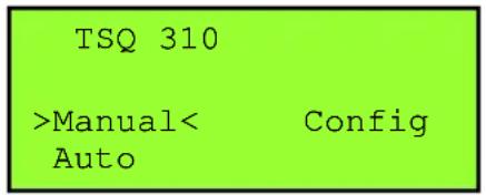
We have to use the "Up" and "Down" buttons of the keyboard in order to move to the different options, and to get into the submenus we have to press "OK" button.
text_image
TSQ 310 >Manual< Config Auto1. Manual
Inside the "manual" menu there are specified the different options for setting up the input, output and modulation parameters.
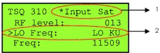
- This field shows the type of parameter that is selected at the moment. Options: Input Sat, Out Cab, Out TV.
- This field shows the parameter that is selected. In order to move around the different options we have to use the "Up" and "Down" buttons of the keyboard.. Click on OK to edit the selected parameter and Right/Left for changing it. Once it is configured press OK.
text_image
TSQ 310 *Input Sat RF level: 013 >LO Freq: LO KU Freq: 11509Satellite input ( Input Sat)
In these options you will be able to configure the input parameters of the satellite signal:
- L.O. freq (Local oscillator): Selection of the local oscillator that you wish to use: FI, KU, C, K9750, K10000, K10600, K10700, K10750, K11250, K11300, K11325.
text_image
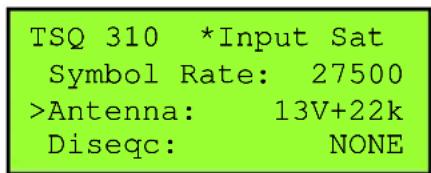
TSQ 310 *Input Sat Symbol Rate: 27500 >Antenna: 13V+22k Diseqc: NONE- Freq (Input Frequency (MHz)): Transponder frequency that you wish to tune. In order to introduce the frequency, press the "OK" button and the cursor will be placed over the frequency. With the keys of the cursor, we can move through all the digits and change the values. Press "OK" in order to save the value.
- Symbol Rate: Symbol speed required by the transponder. In order to introduce the symbol rate, press the "OK" button and the cursor will be placed over the frequency. With the keys of the cursor, we can move through all the digits and change the values. Press "OK" in order to save the value.
- Antenna: Feeding/tone towards the LNC. Options: 0V, 13V, 13V+22kHz, 18V, 18V+22kHz, 13V+AUT, 18V+AUT.
- DiseqC: In this option you can set the DiseqC configuration: A, B, C, D and None.
- Auto SR (Auto Symbol Rate): You will be able to select if the detection of the Symbol Rate is going to be Automatic (On) or Manual (Off).
- In Manual mode (Off), the value of the Symbol Rate should be fixed by the user based on the provider's information.
- In Automatic mode (On), the meter will automatically identify the SR when a Satellite carrier is tuned. This feature is very useful when the provider's information is unknown.
The SR value found will appear in the field of selection of the SR menu. This value found by the meter could not correspond exactly to the real broadcast SR, but to a very close value.

Note: The Automatic Symbol Rate feature does not work when the carrier quality is very poor or/and with a very low Power Level.
- Mode: This option allows selecting the standard DVB of the transponder that you want to tune. Options: DVB-S1, DVB-S2 and auto.
Cable modulator (Out Cable)
This option allows you to configure the DVB-C modulator that the device has.
- Spectrum inversion: Activate or deactivate the spectrum inversion in the modulation.
- Modulation: Modulation Format. Options: 16 QAM, 32 QAM, 64 QAM, 128 QAM, 256 QAM.
- Roll-off factor: Roll-off factor reduces the interference between symbols thanks to the raised cosine filtering, the bigger this value is, the less interference between symbols that will be caused. Typical Value according to rules DVB-C =15%. Options: 1.5, 1.3.
- Symbol speed: The available symbol speed ranges from 1000 to 7000 S/s.
In order to estimate the output symbol speed you have to take into account the following parameters: input modulation, input symbol speed, input FEC, output modulation.
| TSQ 310 * Out Cable Modulacion: 64 >Roll-off: 1.5 Symbol speed: 1000 |
For example, for a 8PSK signal with 22000 MS/s and a FEC 2/3, the output symbol speed should be calculated according to the chosen QAM modulation.
$$ V _ {S Y M B O L. O U T} = \frac {V _ {S Y M B O L . I N ^ {\prime}} \cdot \cdot \cdot (8 P S K) _ {\text { symbol }} ^ {\prime \prime} \left(^ {\circ} 5 2 F E C ^ {2} / _ {3} \cdot 3\right)}{\cdot (\quad)} = \frac {}{(\text { QAMs }) _ {\text { symbol }} ^ {\prime \prime} \text { bitQAMsymboln } ^ {\prime \prime} \text { bit }} $$
| Modulation QPSK | 8PSK 16 QAM 32 QAM 64 QAM | 128 QAM | 256 QAM | ||||
| Number of bits per symbol | 2 | 3 | 4 | 5 | 6 | 7 | 8 |
| Modulation | 16 QAM | 32 QAM | 64 QAM | 128 QAM | 256 QAM |
| Symbol speed (MS/s) | 11000 | 8800 | 7333 | 6286 | 5500 |
Output configuration (TV output)
In these options you can configure the output parameters of the terrestrial signal.
- RF Channel (MHz): Output frequency of terrestrial modulation. In order to introduce the frequency, press the "OK" button and the cursor will be placed over the frequency. With the keys of the cursor, we can move through all the digits and change the values. Press "OK" in order to save the value. Options: 47-862 MHz.
- RF Level: Regulation of the output level of the modulated signal. Options: 0-15dB.
| TSQ 310 | *Out TV |
| >RF Channel: | 474000 |
| RF Level: | 013 |
Summary table:
| Satellite input | Cable output | TV output |
| - L.O. frequency- Input Frequency- Symbol Rate- Antenna- Diseqc- Symbol rate auto- DVB Mode | - Invert (Spectrum Inversion)- Modulation- Roll-off factor- Symbol speed | - RF Channel- RF Level |
2. Auto
This option allows saving and loading the configuration of the module in the PRO 201 programmer.
| TSQ 310 |
| > *Read from Module* |
| *Write to Module * |
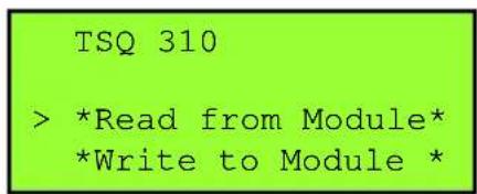
- Read from module: It stores the current configuration of the module in the memory of the programmer. The steps to make a correct reading of the headend are specified below:
text_image
TSQ 310 > *Read from Module* *Write to Module *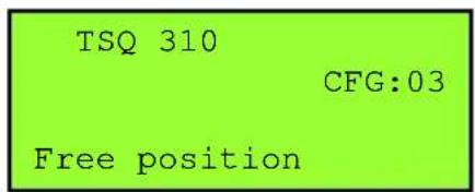
text_image
TSQ 310 CFG:03 Free position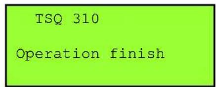
text_image
TSQ 310 Operation finish-
Select the option "Read from module" through Up/Down buttons. Press OK to continue
-
Select the position of "CFG" memory where you wish to save the current configuration of the module.
-
A window will appear and it will let you know that the reading made has been correct
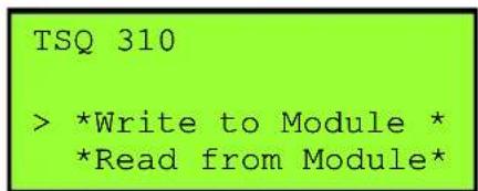
- Write to module: It loads in the module one of the configurations previously saved in the memory of the programmer. The steps to make a correct configuration of the headend are specified below:
text_image
TSQ 310 > *Write to Module * *Read from Module*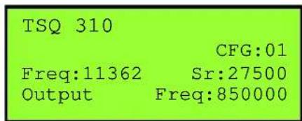
text_image
TSQ 310 CFG:01 Freq:11362 Sr:27500 Output Freq:850000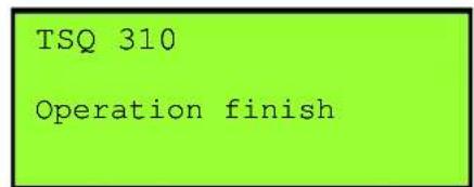
text_image
TSQ 310 Operation finish-
Select the option "Write to module" through Up/Down buttons. Press OK to continue
-
Select the position of the "CFG" memory that you wish to copy in the module. Please verify that the data of the selected memory correspond to the channel that you wish to copy.
-
A window will appear and it will let you know that the configuration made has been correct
-
Config In "Config" option the information concerning the transmodulator is given.
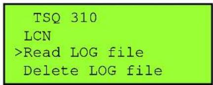
- Read log: It allows reading the registered events in the module.
text_image
TSQ 310 LCN >Read LOG file Delete LOG file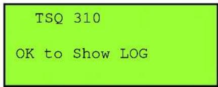
text_image
TSQ 310 OK to Show LOG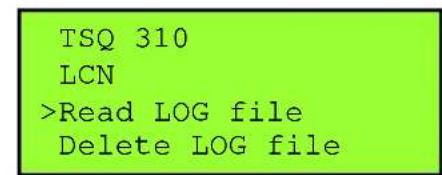
text_image
TSQ 310 LCN >Read LOG file Delete LOG file-
Select the option "Read LOG file" through Up/Down buttons. Press OK to continue
-
Press OK again to show the log file.
text_image
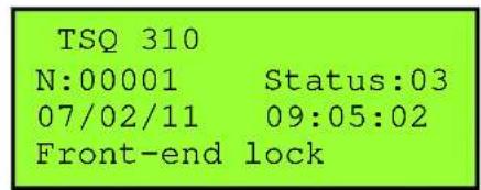
TSQ 310 N:00001 Status:03 07/02/11 09:05:02 Front-end lock-
A new window will appear. It will show the information about the registered events in the module. Press the following keys in order to scroll up and down the screen: "up/down".
-
Delete LOG file: It allows deleting all events stored until this moment.
- Factory default: This option restores the values by default of the transmodulator.
- Update FW: It allows carrying out the firmware update from the programmer.
- Output services: This option allows making the selection of the services that you wish to include in the output multiplex. Once you have tuned a transponder and you have selected the DVB-T/DVB-H modulator configuration, you can make the assignment of the services that are going to be included in the output multiplex "Adding/Removing services".
- Add Services
TSQ 310
BW usage 000%
Delete services
>Add services
TSQ 310
Input 035 %
PID:06200 arte HD
+Add
TSQ 310Operation finish
-
Select the option "Add services" through Up/Down buttons. Press OK to continue.
-
Select one of the transponder services you want to add, through Left/Right keys and select the "+Add" button to include the service in the multiplex
-
A window will appear and it will let you know that the operation made has been correct.
- Delete Services
TSQ 310
BW usage 083%
>Delete services
Add services
TSQ 310Operation finish
-
Select the option "Delete services" through Up/Down buttons. Press OK to continue.
-
Select the service you want to delete with the Left/Right keys. Then press OK over "-Rem" in order to remove it, or press OK over "--All" in order to delete all the services of the multiplex.
-
A window will appear and it will let you know that the operation made has been correct.

Note: It is not recommended to exceed the 85% of the maximum capacity of the multiplex due to the possible variability of the bits rate of the inputs services.
- LCN: The LNC function allows assigning automatically a predetermined position to each one of the services of the multiplex. This function will allow the users who have a receiver with LNC support to make the ordination of channels automatically. Select a channel through Left/Right buttons and introduce the position. Press the "OK" button and the cursor will be placed over the number. With the keys of the cursor, we can move through all the digits and change the values. Press "OK" in order to save the changes
TSQ 310
LCN:00004 arte HD

Note: If in the existing installation there are already services that have LNC system, you will have to configure the position of the module services in order to avoid conflicts with other net services.
- Date / Hour: Setting of the date and time of transmodulator. It is appropriate to maintain these parameters set in order to have the registration of errors linked to the current time and date.
- SW version info: It allows you to visualize the basic information of the module: model, firmware version, etc.
- Global Update: It allows carrying out the update of all the modules that are interconnected at the same time.
1.5. Accessories and example of installation
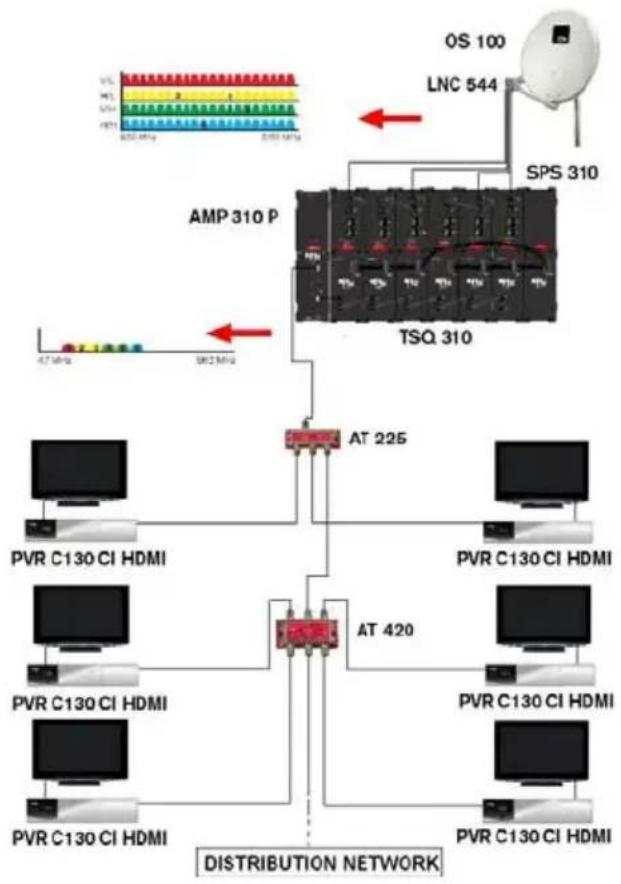
Example of installation
flowchart
graph TD
    A["AMP 310 P"] --> B["TSQ 310"]
    B --> C["AT 225"]
    C --> D["PVR C130 CI HDMI"]
    C --> E["AT 420"]
    E --> F["PVR C130 CI HDMI"]
    E --> G["PVR C130 CI HDMI"]
    H["OS 100"] --> I["LNC 544"]
    I --> J["SPS 310"]
    K["DISTRIBUTION NETWORK"] --> L["AT 225"]
    M["47 MHz"] --> N["862 MHz"]
Installation that consist of 6 TSQ 310 and that will allow tuning channels up to 6 different transponders and to distribute them through a network of modulated cable in DVB-C. The distributed channels need a cable receiver in order to be decoded, in this case we propose a PVR C130 CI HDMI receiver that would decode free channels and also encoded channels if we insert a PCMCIA with the corresponding subscriber card.

In order to guarantee the right running of the different equipments of the installation, we recommend you to provide the inputs and outputs which are not used with a 75Ω load.
Accessories
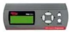
Programmer
Mod. PRO 201
Code 2003123
text_image
Scanned document with dense text, likely a formal letter or official recordField strength meter
Mod.mediaMAX EVO S2
Code 3001006

text_image
IN OUT
Field strength meter
Mod. mediaMAX MINI S2T
Code 3001026
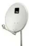
Parabolic antenna OS series
Mod. OS 100 AL
Code 0701100
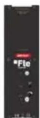
Wide band amplifier 47-862MHz
Mod. AMP 310 P
Code 2003520
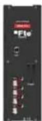
Mixer
Mod. MUX 310
Code 2003518
Chapter 2. Technical features
| Ref. | TSQ |
| Code 2003532 | |
| Input frequency margin 950-2150 MHz | |
| Input level -25 a -65 dBm | |
| Imput impedance | 75Ω |
| LNB (feeding/conmutation) 13V-18V / 0-22kHz | |
| Input connector Female F connector | |
| Input LOOP losses <1 dB | |
| FEC | 1/2, 2/3, 3/4, 5/6, 7/8, 8/9, 9/10, 1/4, 1/3, 1/5, 2/5, 3/5, 4/5 DVB, RS 204,188 |
| Input modulation 8PSK, QPSK | |
| Input Symbol Rate DVB-S:1-45 MS/s / DVB-S2:1-37 MS/s | |
| Modulation Error Ratio (MER) Typ. 40 / Min. 36 | |
| Selectable format of output modulation 16 QAM, 32 QAM, 64 QAM, 128 QAM, 256 QAM | |
| Output symbol Rate 1-6,96 MS/s | |
| Roll-Off Factor 13 %,15% | |
| Output channels | C2-C69 |
| Output connectores | Female F connector |
| Output Level | 80 dBuV |
| Regulation margin | 15 dB |
| MIX Losses | <1 dB |
| Band spurious | -60 dBc |
| Programming Interface RJ-45 | |
| Programmer | PRO 201, media Max EVO and media Max MINI |
| Operating temperature | 0°C-45°C |
| Consumption 5V (mA) | 800 |
| Consumption 12V (mA) | 300 |
| Consumption 24V (mA) | 15 |
| Consumption 30V (mA) | 2 |
| Dimensions 75x265x150 mm | |
| Weight | 1,4Kg |
Chapter 3. Declaration of conformity

text_image
C€CONFORMITY DECLARATION
"WE, FTE MAXIMAL, DECLARE THAT THE PRODUCT
TSQ 310
IS IN CONFORMITY WITH FOLLOWING DIRECTIVES
Low Voltage Directive 2006/95/EC
EMC Directive 2004/108/EC"
If you wish a copy of the conformity declaration, please contact to the company