
XE2000C - Uncategorized ESX - Free user manual and instructions
Find the device manual for free XE2000C ESX in PDF.


| Product Type | Power Capacitor for Car Audio |
| Brand | ESX |
| Model | XE2000C |
| Capacity | 2.0 Farad +/- 10% |
| Continuous Voltage Range | 11 - 16V DC |
| Operating Temperature | -40 to 80°C |
| Equivalent Series Resistance (ESR) | 0.0015 Ohm @ 120Hz / 25°C |
| Dimensions (Diameter x Length) | ∅76 x 325 mm |
| Digital Voltmeter | Yes, displays operating voltage |
| Control LED | Flashes on voltage fluctuations or drop |
| Audio Warning | Audible alert on reverse polarity |
| Remote Terminal | For connection to head unit remote wire |
| Potentiometer | Adjusts voltmeter reading |
| Mounting Brackets | Included (top and bottom) |
| Charging/Discharging Light Bulb | Included |
| Application | Stabilizes 12V supply, supports car audio amplifiers, filters AC noise |
| Safety Features | Warnings: electrical hazard, explosion risk; use light bulb for initial charge |
| Installation Note | Mount near amplifier, use short thick cables, same ground as amplifier |
| Discharging Requirement | Use supplied light bulb; never short circuit |
Frequently Asked Questions - XE2000C ESX
User questions about XE2000C ESX
0 question about this device. Answer the ones you know or ask your own.
Ask a new question about this device
Download the instructions for your Uncategorized in PDF format for free! Find your manual XE2000C - ESX and take your electronic device back in hand. On this page are published all the documents necessary for the use of your device. XE2000C by ESX.
USER MANUAL XE2000C ESX
natural_image
Abstract geometric logo design with stylized letter 'S' and intersecting lines (no text or symbols)CAR AUDIO SYSTEMS
XE1200C
1.2 FARAD POWER CAPACITOR
XE2000C
2.0 FARAD POWER CAPACITOR
BEDIENUNGSANLEITUNG


MONTAGE
Safety Instructions 11
Installation 12
Initial Charging Process 12
Wiring Diagram 13
Functional Descriptions 14
Discharging Process 15
Voltmeter Adjustment 15
SPECIFICATIONS
XE1200C
Capacity: 1.2 Farad +/- 10%
Continuous Voltage: 11 \~ 16V DC
Operation temperature: -40 80^
E.S.R.: 0,0015 Ohm @ 120hz / 25°
Dimensions: ø76 x 280 mm
XE2000C
Capacity: 2.0 Farad +/- 10%
Continuous Voltage: 11 \~ 16V DC
Operation temperature: - 40 \~ 80°C
E.S.R.: 0,0015 Ohm @ 120hz / 25°
Dimensions: ∅76 x 325 mm
KIT INCLUDED
1 Power Capacitor
2 Mounting Brackets (top and bottom)
1 Charging-/discharging light bulb
1 Owner's Manual
Hardware Package
APPLICATIONS
The power capacitor is used in vehicles for stabilizing the 12 Volt supply and support for car audio amplifiers, if fast and temporary high currents are required. The power capacitor can compensate short-term power peaks on the on-board electrical system for low and powerful bass operations.
The use of the power capacitors results in a considerably improved power expansion of the amplifier.
Car audio amplifiers require very high current peaks for a proper operation. Conventional car batteries are not designed to deliver additional power to car audio amplifiers.
Another feature of this power capacitor is to filter car AC voltage included by the amplifier power supply. This can cause audible interferences in the audio signal.
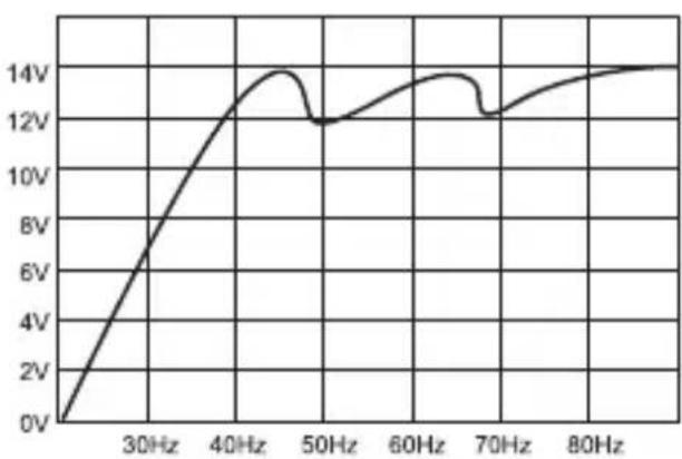
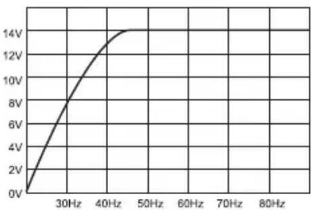
Bassperformanze at 50Hz and 70Hz without capacitor
line
| Frequency | Voltage | | --------- | ------- | | 0 | 0V | | 30Hz | ~6V | | 40Hz | ~14V | | 50Hz | ~12V | | 60Hz | ~14V | | 70Hz | ~12V | | 80Hz | ~14V |Bassperformanze at 50Hz and 70Hz with capacitor
line
| Frequency | Voltage | | --------- | ------- | | 30Hz | 0V | | 40Hz | 8V | | 50Hz | 14V |SAFETY INSTRUCTIONS
Before you begin with the installation, please attend the following advices in this manual. Otherwise the risk of injury or a damage of the device consists.
The power capacitor is equivalent to common directives to be operated in vehicles inside the European Union and owns a CE-mark.
The capacitor should be installed by qualified and skilled personnel only. Special carefulness is essential, because in case of short circuits hazardous high currents could occur.
The power capacitor stores an extremely large amount of electricity and may explode or cause serious injury. If the device is used for other purposes than originally intended or if not proper used or installed, personal injury or material damage could occur.
The capacitor should be mounted at a mechanically stable position in the vehicle. The device should be fixed properly and professional.
At no time the power capacitor should be exposed to voltages higher than specified or its terminals shorted directly.
Protect the capacitor against humidity and heat.
For cleaning use a dry and soft cleaning tissue, by no means any chemicals or water.

WARNING! ELECTRICAL HAZARD

INSTALLATION
For achieving the best results the capacitor should be located close-by the amplifier. The cables between capacitor and amplifier should be short as possible and should have large cross section. While installing the cables or the operation, ensure not to damage the insulation of the cables.
1.) Tightly screw the device with the supplied brackets and screws as close as possible to the amplifier on a mechanically stable position. By no means install the capacitor on any kind of speaker enclosure or on high vibrating positions.
2.) The correct wiring is displayed on the next page. To avoid any interferences, connect the capacitor's ground connection at the same ground terminal like the amplifier.
INITIAL CHARGING PROCESS
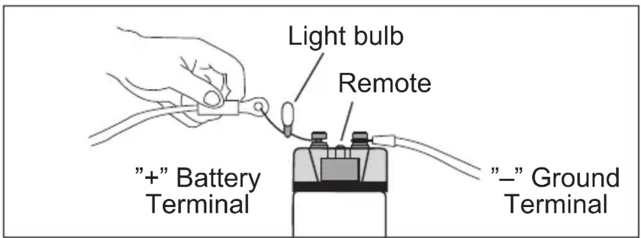
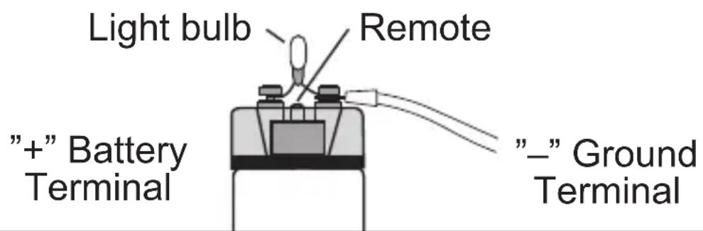
For the first initial charging use by any means the supplied light bulb, to limit the charge current and to avoid connecting sparks. Connect the “—” ground wire with the “—” terminal of the capacitor. Then connect the remote-wire of the head unit with the remote-terminal on the capacitor.
Then clamp the supplied light bulb to the "+" terminal of the capacitor and hold the "+" wire of the battery or distribution block at the other end of the light bulb..
The light bulb can be disconnected after approx. one minute or if the capacitor reached a load of 10 volts. Then connect the “+” terminal of the battery with the “+” terminal of the capacitor to complete the charging process until 12\~14 volts are achieved.
During the charging process (between 5 \~ 10 Volt) a sound blip is hearable! The light bulb may get very hot during the charging process. Please avoid any short circuit on the terminals.
WIRING DIAGRAM
Wiring with Distribution Block (recommended)
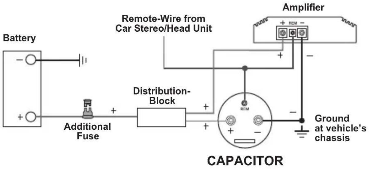
flowchart
graph LR
    A["Battery"] --> B["+"]
    C["Additional Fuse"] --> D["+"]
    E["Distribution-Block"] --> F["+"]
    G["Capacitor"] --> H["Ground at vehicle's chassis"]
    I["Remote-Wire from Car Stereo/Head Unit"] --> J["+"]
    K["Amplifier"] --> L["Ground at vehicle's chassis"]
Important Note: Please ensure the correct polarity for all connections!
Wiring without Distribution
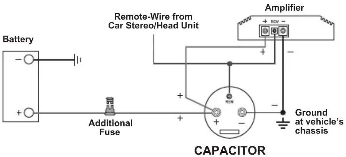
Important Note: Please ensure the correct polarity for all connections!
FUNCTIONAL DESCRIPTIONS
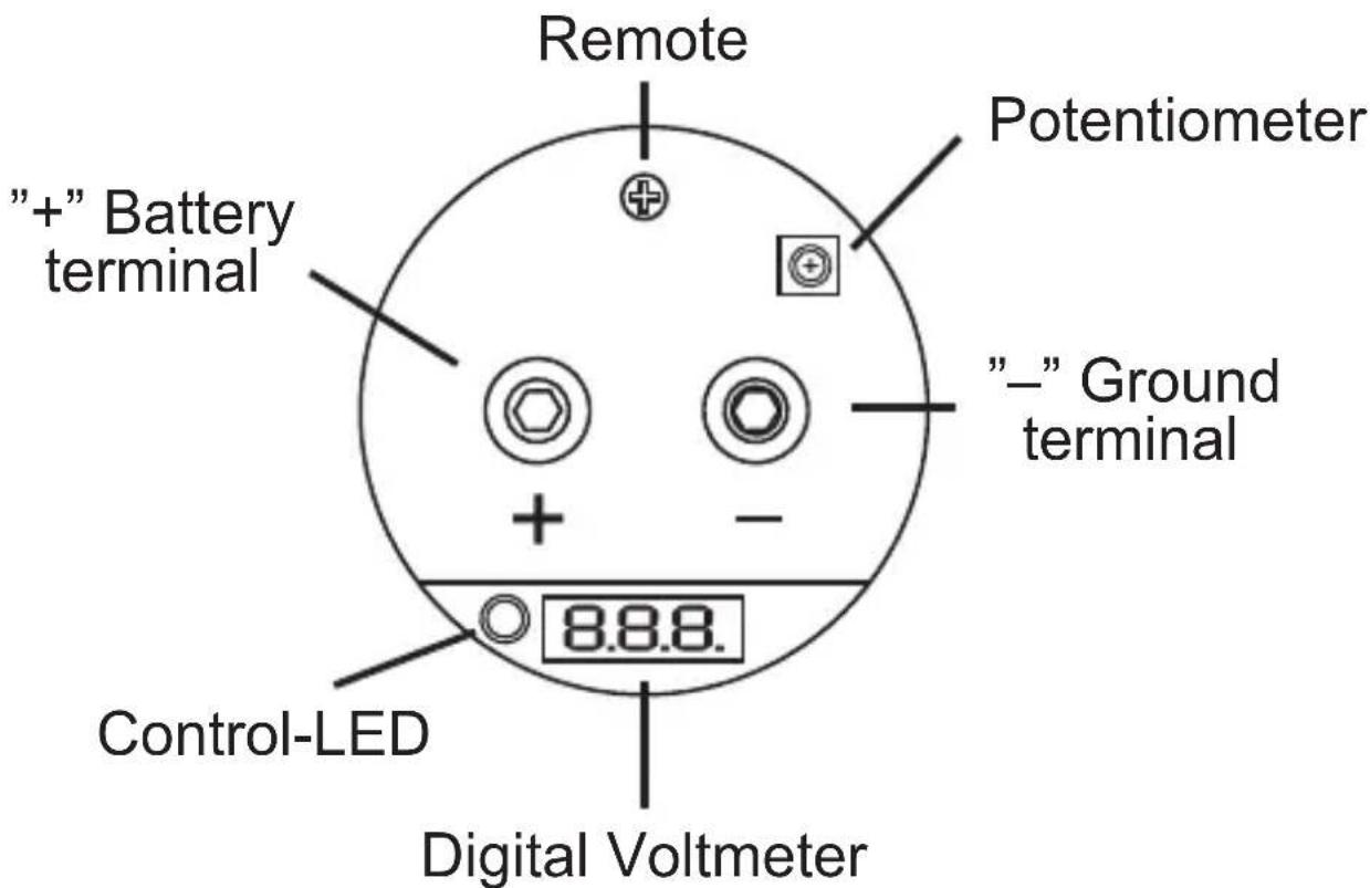
Digital Voltmeter
This display indicates the actual operating voltage and is one of the most important features to display the status of the car's power supply.
The voltmeter is working only when a 12 Volt connection on the remote terminal is connected and a voltage of 5 \~ 10 Volts is connected to the power terminals.
During the charging process (5 \~ 10 Volts) or if the voltage falls under 10 Volts a sound blip is hearable.
Control-LED
If major voltage fluctuations or a fall of voltage is occurred, the Control-LED starts flashing. In this case, you need to check on-board power system or the power terminals on faulty connections.
Audio Warning
If a interchange of the poles is occurred, an audio warning is hearable.
In this case disconnect all connections directly. Danger of Explosion!
Remote
This terminal should be connected with the remote wire of the amplifier or head unit. This prevents, that the vehicle's battery discharge, if the car audio system is not in use.
Potentiometer
This controller allows to adjust the voltmeter. Attend the information on Page 15.
DISCHARGING PROCESS
If the capacitor will be de-installated you need to discharge it completely. To discharge the capacitor, remove the wire at the "+" terminal of the capacitor. Keep the ground terminal "-" connected. Then bridgeover the "-"pole and "+"pole of the capacitor with the supplied light bulb.
The discharging process could last some minutes.
To checkup the status, the remote signal (head unit ON) has to be turned on. It is recommended to use a gripper during this procedure, because the light bulb may get very hot.
A sound blip is hearable during the discharging (below 10 Volts) and the Control-LED is flashing. If the light bulb stops flashing, the discharging process is accomplished.
Never discharge the capacitor without the supplied light bulb.
Never discharge the capacitor with bypassing the terminals (short circuit). The capacitor may get damaged or explode.
VOLTMETER ADJUSTMENT
The adjustment is already done by the factory, but can be redone if necessary. By using additional capacitors, various indicated values could be occurred. This can be adjusted by the potentiometer.
Follow these instructions:
1.) Measure the actual operating voltage on the "+" und "-"pole of the capacitor by using an appropriate multimeter.
2.) Remove the plexi-cover of the capacitor and adjust the value with the potentiometer by using a appropriate screwdriver to the same value, you have measured before.
3.) Ensure while removing the cover, not to short the terminals.
4.) Or assign your car audio retailer.

natural_image
Abstract geometric logo design with stylized letter 'S' and diagonal line (no text or symbols)CAR AUDIO SYSTEMS

Audio Design GmbH
Am Breilingsweg 3, D-76709 Kronau/Germany
Tel. +49(0)7253/9465-0, Fax +49(0)7253/946510
www.esxaudio.de

- CAR AUDIO SYSTEMS
- XE1200C
- XE2000C
- BEDIENUNGSANLEITUNG
- MONTAGE
- SPECIFICATIONS
- KIT INCLUDED
- APPLICATIONS
- SAFETY INSTRUCTIONS
- WARNING! ELECTRICAL HAZARD
- INSTALLATION
- INITIAL CHARGING PROCESS
- WIRING DIAGRAM
- FUNCTIONAL DESCRIPTIONS
- Digital Voltmeter
- Control-LED
- Audio Warning
- Remote
- Potentiometer
- DISCHARGING PROCESS
- The discharging process could last some minutes.
- VOLTMETER ADJUSTMENT
- Follow these instructions:
Brand : ESX
Model : XE2000C
Category : Uncategorized