ICF-1150-S-SC-T - Uncategorized Moxa - Free user manual and instructions
Find the device manual for free ICF-1150-S-SC-T Moxa in PDF.


User questions about ICF-1150-S-SC-T Moxa
0 question about this device. Answer the ones you know or ask your own.
Ask a new question about this device
Download the instructions for your Uncategorized in PDF format for free! Find your manual ICF-1150-S-SC-T - Moxa and take your electronic device back in hand. On this page are published all the documents necessary for the use of your device. ICF-1150-S-SC-T by Moxa.
USER MANUAL ICF-1150-S-SC-T Moxa
First Edition, November 2008
MOXA®
© 2008 Moxa Inc. All rights reserved. Reproduction without permission is prohibited.
Fl.4, No.135, Lane 235, Pao-Chiao Rd. Shing Tien City, Taipei, Taiwan, R.O.C.
TEL: +886-2-8919-1230
P/N: 1802011500010
Overview
Introduction
The ICF-1150 series fiber converters are equipped with a multiple interface circuit that can handle RS-232 and RS-422/485 serial interfaces, as well as multi-mode or single-mode fiber. The ICF-1150 series converters are used to extend serial transmission distance up to 5 km (ICF-1150-M, with multi-mode fiber) or up to 40 km (ICF-1150-S, with single-mode fiber).
Why Convert Serial to Fiber?
Fiber communication not only extends the communication distance, but also provides many advantageous features. IMMUNITY FROM ELECTRICAL INTERFERENCE: Fiber is not affected by electromagnetic interference or radio frequency interference. It provides a clean communication path and is immune to cross-talk. INSULATION: Optical fiber is an insulator; the glass fiber eliminates the need for using electric currents as the communication medium. SECURITY: Fiber cannot be tapped by conventional electric means and is very difficult to tap into optically. Furthermore, radio and satellite communication signals can be captured easily for decoding. RELIABILITY & MAINTENANCE: Fiber is immune to adverse temperature and moisture conditions, does not corrode or lose its signal, and is not affected by short circuits, power surges, or static electricity.
Reverse Power Protection
The Reverse Power Protection feature provides extra protection against accidentally connecting the power cables to the wrong terminal. The converter is designed to detect automatically which power wire is positive and which is negative, and then adjust the power supply accordingly.
3-Way Communication
The ICF-1150 series supports 2 serial ports. The D-sub connector is for RS-232 communication and the removable terminal block is for RS-422 or RS-485 communication. The 3 ports (2 serial ports and one fiber port) are completely independent. When the ICF-1150 series converters receive data from any port, it will send data out through the other 2 ports. For example, when the ICF-1150 series converters receive a command from the remote Master via the fiber port, it will convert the command and transmit it via the RS-232 port and RS-422/485 port at the same time. So if the user is trying to monitor a system running on the RS-485 network, there is no need to use an additional RS-232 to RS-485 converter to connect the laptop computer's serial port to the RS-485 bus.

ATTENTION
ICF-1150 is designed to receive data from one port and send data to the other ports.
If ICF-1150 receive data from 2 ports at the same time, that may cause the data error on all the RX ports.
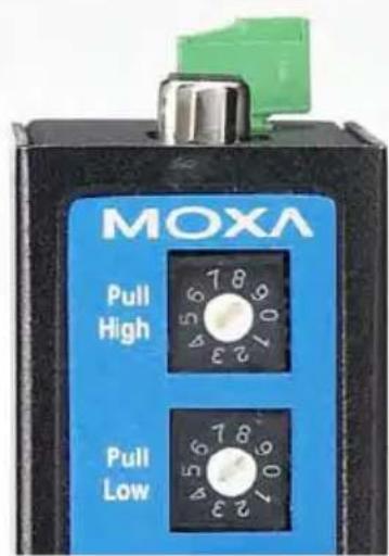
Rotary Switch for Pull High/Low Resistor Setting
Since the RS-485 port can support multi-drop connection or daisy-chain connection, system engineers can connect meters, RTUs, readers, or many other devices together on the same bus. The impedance of the data line will rise according to the number of serial devices on the same bus. To get the system working, the ICF-1150 has a setting for tuning the pull high/low resistor. Just turn the dial to find the best resistor value for the system without removing the ICF-1150 from the DIN-rail. (The default settings are 1K for both switches.)
text_image
MOXA Pull High Pull LowPull High/Low Resistor
| Position | 0 | 1 | 2 | 3 | 4 | 5 | 6 | 7 | ||||||||
| Ohm | 150K | 10K | 4.7K | 3.3K | 1K | 909 | 822 | 770 |
DIP Switch for Selectable Terminator
The termination resistor for many products of this type is set by a jumper located inside the product's casing. To disable or change the resistor's strength, the user must open the casing to reset the jumper. Moxa offers a more user-friendly solution that allows users to set the termination resistor with a DIP switch located outside the ICF-1150 converter's casing.
No Configuration Required for Baudrate Settings
The ICF-1150 works under any baudrate from 50 bps to 921.6 Kbps. The ICF-1150 simply converts the signal back and forth between serial (RS-232, RS-422, or RS-485) and fiber. Since the ICF-1150 does not need to interpret the signal, it does not need to know the baudrate of the transmitting device. For this reason, the ICF-1150 does not have any DIP switches or jumpers for setting the baudrate.
Ring Mode
To allow one half-duplex serial device to communicate with multiple half-duplex devices connected to a fiber ring, you should configure the ICF-1150 for “ring mode” by setting DIP switch “SW3” to the “On” position. The Tx port of a particular ICF-1150 unit connects to the neighboring converter’s Rx port to form the ring. Note that when one node transmits a signal, the signal travels around the ring until it returns back to the transmitting unit, which then blocks the signal. Users should ensure that the total fiber ring length is less than 100 km when using either single-mode models or multi-mode models.
Features
- “Ring” or “Point to Point” transmission
- Extend RS-232/422/485 transmission distance:
up to 40 km with single-mode—ICF-1150-S series
up to 5 km with multi-mode—ICF-1150-M series
• Support baudrate up to 921.6 Kbps
- Provide 3-way galvanic isolation (for -I models)
- Wide operating temperature from -40 to 85°C (for "T" models)
Package Checklist
Before installing the ICF-1150, verify that the package contains the following items:
• ICF-1150 Fiber Converter
- Quick Installation Guide
- Warranty Card
NOTE: Please notify your sales representative if any of the above items are missing or damaged.
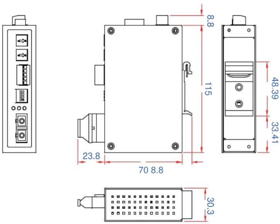
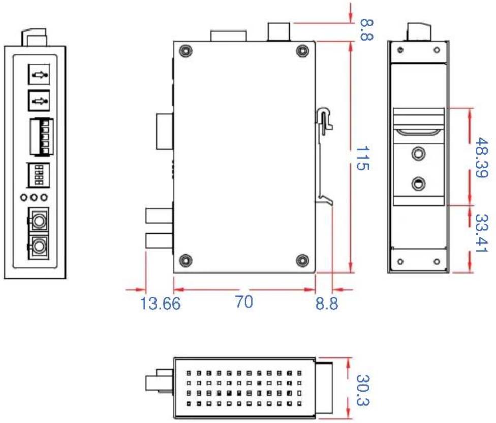
Mounting Dimensions (Unit : mm)
ICF-1150-SC
ICF-1150-ST
Top View
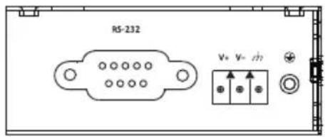
text_image
RS-232 V+ V- 0/2Front View
Rotary Switch for Pull High/Low Resistor
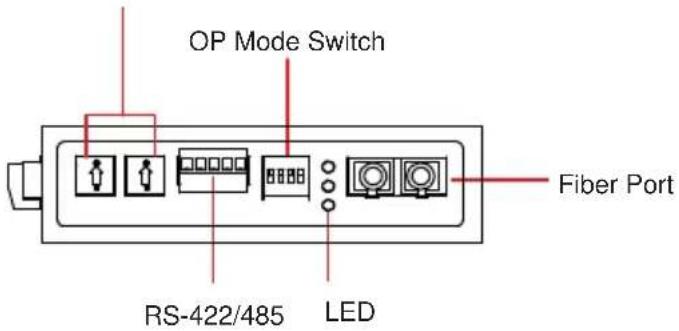
text_image
OP Mode Switch Fiber Port RS-422/485 LEDATTENTION

Electrostatic Discharge Warning!
To protect the product from damage due to electrostatic discharge, we recommend wearing a grounding device when handling your ICF-1150 series.
Mounting
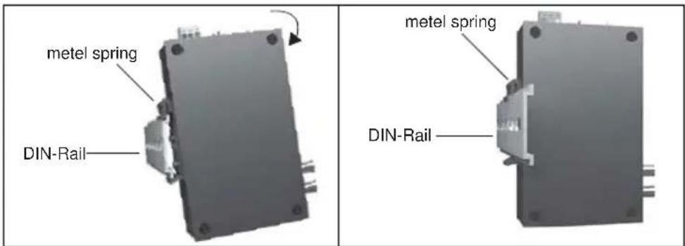
The aluminum DIN-Rail attachment plate should be fixed to the back panel of the ICF-1150 when you take it out of the box. If you need to reattach the DIN-Rail attachment plate to the ICF-1150, make sure the stiff metal spring is situated towards the top, as shown in the figures below.
STEP 1:
Insert the top of the DIN-Rail into the slot just below the stiff metal spring.
STEP 2:
The DIN-Rail attachment unit will snap into place as shown below.
text_image
metel spring DIN-Rail metel spring DIN-RailTo remove the ICF-1150 series from the DIN-Rail, simply reverse Steps 1 and 2 above.
Pin Assignment
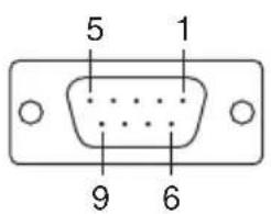
text_image
5 1 9 6| Pin RS-232 | |
| 1 | Null |
| 2 | TxD |
| 3 | RxD |
| 4 | Null |
| 5 | GND |
| 6 | Null |
| 7 | Null |
| 8 | Null |
| 9 | --- |
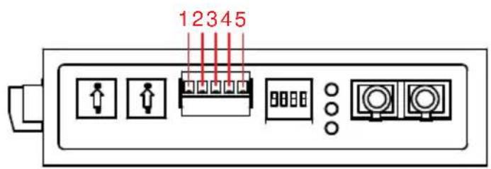
text_image
12345| RS-422 4-wire RS-485 2-wire RS-485 | |||
| 1 | GND | GND | GND |
| 2 | Rx- | Rx- | Data |
| 3 Rx | + Rx + Data + | ||
| 4 Tx | - Tx - | ||
| 5 Tx | + | Tx + | |
Fiber Cable
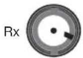
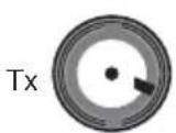
SC-Port Pinouts SC-Port to SC-Port Cable Wiring
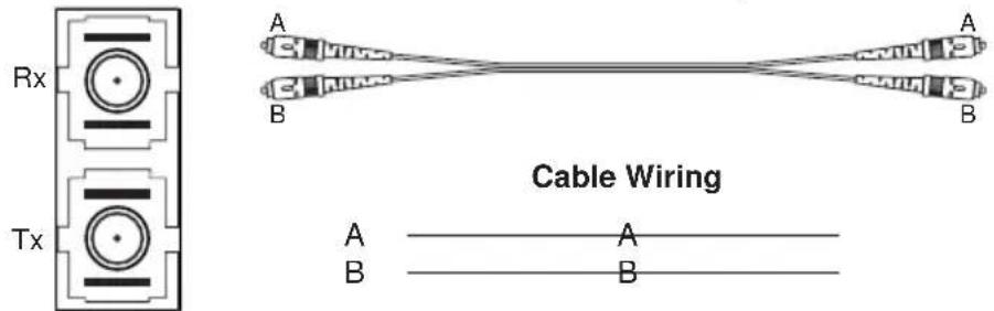
ST-Port Pinouts
ST-Port to ST-Port Cable Wiring
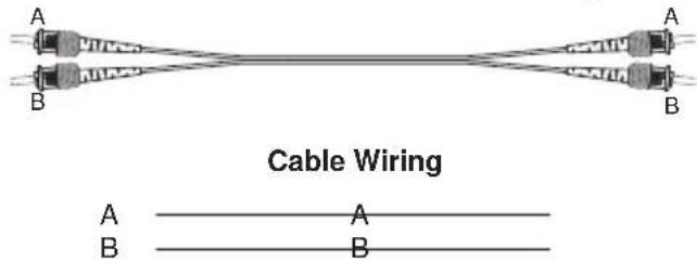
This is a Class 1 laser/LED product. Do not stare into the laser beam.
Switch Settings
There are 4-DIP switches on the front panel of the ICF-1150.
| Setting Switch 1 Switch 2 | |||
| RS-422 | ON | OFF | |
| 2-wire RS-485 | OFF ON | ||
| 4-wire RS-485 | OFF (default) | OFF (default) | |
| Fiber Mode Switch 3 | |
| Ring Mode ON | |
| Point to Point mode | OFF (default) |
| 120Ω Terminator | Switch 4 |
| Enable | ON |
| Disable | OFF (default) |
ATTENTION

For Fiber Ring Users:
If the Rx LEDs of the converter glow continuously, remove the fiber cable and connect again, then the system will not have the same condition.
NOTE: “Ring Mode” can only be used for half-duplex applications.
LED Indicators
There are 3 LEDs on the front panel of the ICF-1150.
| LED Color Function | |
| PWR Green Steady ON: Power is ON | |
| Fiber Tx Green When sending serial data from the fiber port | |
| Fiber Rx Yellow When receiving data from the fiber port | |
Specifications
Serial Communication
Signals for RS-232 TxD, RxD, SGND
Signals for RS-422 TxD+, TxD-, RxD+, RxD-, SGND
Signals for 4-wire RS-485 TxD+, TxD-, RxD+, RxD-, SGND
Signals for 2-wire RS-485 Data+, Data-, SGND
Baudrate 50 bps to 921.6 Kbps
ESD protection 15 KV ESD
Fiber Communication
Connector type ST or SC
Distance Single-mode fiber for 40 km
Multi-mode fiber for 5 km
Support Cable : 8.3/125, 8.7/125, 9/125 or 10/125 μm
(single mode)
50/125, 62.5/125, or 100/140 μm
(multimode)
Wavelength ICF-1150-S: 1310 nm
ICF-1150-M: 850 nm
TX Output ICF-1150-S: > -5 dBm
ICF-1150-M: > -5 dBm
RX Sensitivity ICF-1150-S: -25 dBm
ICF-1150-M: -20 dBm
Point-to-Point Transmission Half or Full duplex
Multi-drop Transmission Half duplex, fiber ring
Environmental
Operating Temperature 0 to 60°C (32 to 142°F), 5 to 95 % RH
-40 to 85°C (-40 to 167°F) for -T Model
Storage Temperature -40 to 85°C (-4 to 185°F), 5 to 95 % RH
Power
Input Power Voltage 12 to 48 VDC
Power Line Protection 4 KV Burst (EFT), EN61000-4-4
2 KV Surge, EN61000-4-5
Reverse Power Protection Protects against V+/V- reversal
Protects against 2 signals shorted together: 1.1A
Over Current Protection Protects against 2 signals shorted to 1.1A
Power Consumption ICF-1150-S/M-SC/ST: 127 mA @ 12V
Mechanical
Dimensions (W × D × H) 30.3 × 70 × 115 mm
Material Aluminum (1 mm)
Gross Weight 135g
Regulatory Approvals
CE Class B
FCC Part 15 sub Class B
TÜV EN 60950-1
EMI EN55022 1998, Class B
EMS EN61000-4-2 (ESD), Criteria B, Level 4
EN61000-4-3 (RS), Criteria A, Level 3
EN61000-4-4 (EFT), Criteria B, Level 4
EN61000-4-5 (Surge), Criteria A, Level 3
EN61000-4-6 (CS), Criteria A, Level 3
En61000-4-8 (PFMF), Criteria A, Level 5
Free fall IEC 60068-2-32
MTBF 792085 hrs
Technical Support Contact Information
www.moxa.com/support
Moxa Americas:
Toll-free: 1-888-669-2872
Tel: +1-714-528-6777
Fax: +1-714-528-6778
Moxa China (Shanghai office):
Toll-free: 800-820-5036
Tel: +86-21-5258-9955
Fax: +86-10-6872-3958
Moxa Europe:
Tel: +49-89-3 70 03 99-0
Fax: +49-89-3 70 03 99-99
Moxa Asia-Pacific: