
ARU108MK2 - Uncategorized Audac - Free user manual and instructions
Find the device manual for free ARU108MK2 Audac in PDF.


User questions about ARU108MK2 Audac
0 question about this device. Answer the ones you know or ask your own.
Ask a new question about this device
Download the instructions for your Uncategorized in PDF format for free! Find your manual ARU108MK2 - Audac and take your electronic device back in hand. On this page are published all the documents necessary for the use of your device. ARU108MK2 by Audac.
USER MANUAL ARU108MK2 Audac
PROFESSIONAL AUDIO EQUIPMENT
1/4/8/16 Zone Digital Paging Station (APM), 4/8/16 Digital Receive/Switch Module (ARU/AVD).
User manual & Installation Guide
AUDAC PROFESSIONAL AUDIO EQUIPMENT
User manual & Installation Guide
© AUDAC
http://www.audac.bc
info@audac.be
Index
INTRODUCTION 3
APM P AGING TABLE 3
ARU/AVD RECEIVE/SWITCH MODULE 5
ARU MODULE 6
AVD MODULE 6
ACCESSORIES APM PAGING TABLE....7
SAFETY REQUIREMENTS....8
CAUTION - SERVICING 8
OVERVIEW DIFFERENT APM MODELS 9
APM 16: 9
APM 08: 9
APM 04:....10
AMP01: 10
OVERVIEW DIFFERENT ARU / AVD MODULES....12
ARU04 12
ARU08 12
ARU16....12
AVD04....13
AVD08....13
AVD16....13
RJ-45 PIN CONNECTIONS....14
ATTENTION....14
POWER SUPPLY 15
MAXIMUM RATED CURRENT 15
VOLTAGE DROP ACROSS THE CABLE 15
GETTING STARTED....16
APM: 16
ARU: 17
CONNECTIONS ARU08 18
JUMPER SETTINGS FOR AUDIO ROUTING 19
AVD: 20
C CONNECTIONS A VD08: 20
WORKING PRINCIPLES OF THE ARU/AVD IN COMBINATION WITH THE APM....21
POSSIBILITY 1: APM01 DIRECTLY ON A PRIORITY INPUT OF A MIXING AMPLIFIER....21
POSSIBILITY 2: N LARGER INSTALLATIONS WHICH HAVE AN AMPLIFIER FOR EACH ZONE (SWITCHING ON LINE LEVEL)....22
POSSIBILITY 3: SWITCHING ON LINE LEVEL, INCLUDING EMERGENCY CALL ON VOLUME CONTROLS. 23
POSSIBILITY 4: USING TWO SEPARATE AMPLIFIERS FOR MUSIC AND PAGING. 24
POSSIBILITY 5: SWITCHING ON LOUDSPEAKER LEVEL, INCLUDING EMERGENCY CALL ON VOLUME CONTROLS....25
WIRE UP THE SYSTEM....26
ARJ03 MODULE 26
BUS STRUCTURE 27
ONE STARPOINT....27
MULTIPLE STARPOINTS 28
This section briefly describes the functionality of the APM/ARU/AVD
paging system.
The Audac Paging System was developed as a simple, flexible solution for evacuation and paging systems.
APM Paging Table:
This table microphone with zone-selection is equipped with a digital audio memory which allows storing all necessary “gong” signals.
The gooseneck microphone is equipped with a electret capsule with cardioïd sound pattern. A built-in Compressor/Limiter with Automatic Gain Control controls the output level of the unit.
There's also an indication on the front plate, to give the person who's talking an impression of his voice level.
The complete operation, from microphone till output including all digital parts, is guarded. In case of malfunction, there is a fault-indication. This is to make sure that when there is an emergency call, the message arrives at the listeners.
When there are several paging units placed in a bus-structure, you can configure them with different priority levels. The status of the audio-bus is indicated on the front panel (enable led). All these configurations can be made in a very simple way with the free software tool “AUDAC CONFIGURATION MANAGER”. This tool can be downloaded for from the AUDAC website (www.audac.be).
There are 4 basic models:
- APM 01: Paging Unit just for General announcements.
- APM 04: Paging Unit with 4 Zone Buttons, "Select All"-, "Clear"- and "Talk"-button.
- APM 08: Paging Unit with 8 Zone Buttons, "Select All"-, "Clear"- and "Talk"-button.
- APM 16: Paging Unit with 16 Zone Buttons, "Select All"-, "Clear"- and "Talk"-button.
The lower function buttons are standard programmed with following functions: a “Select All” button to activate all Paging Zones, a “Clear” button to deactivate all Paging Zones. The remaining buttons are used for Zone-Selection or other switch-functions.
All the buttons are free programmable with the "AUDAC CONFIGURATION MANAGER".
Following buttons are standard:
- Talk: By pressing this button, the “gong” starts to play. After this, you can make an announcement through the microphone.
- Select All: By pressing this button, all "Zone" buttons will be selected at once.
- Clear: This button deselects all selected "Zone" buttons.
Following functions are free programmable:
- Zone-select: Press one time to select a Paging Zone. Pressing a second time will deselect the Zone. By pressing “Talk”, the selected Zone will be switched.
- Power Up delay: This is a function for switching on/off several devices. The step-time is adjustable on the receive/switch unit with a small trimmer.
- Pulse Relay: By pressing a button, this function will activate a relay. This relay stays activated as long as you keep the button pressed down (Press and hold function) (e.g. To open a door with electrical door contact).
- Toggle Relay: By pressing a button, this function will activate a relay. By pressing the button again, Toggle relay will deactivate the relay (Set-Reset function) (e.g. Switching lights,...).
- Select Layer 0: Using layers (max. 3 layers) makes it is possible to expand the Paging Unit. By pressing this button, Layer 0 will be activated.
- Select Layer 1: Press this button to activate layer 1.
- Select Layer 2: Press this button to activate layer 2.
Following functions are available in "Service mode":
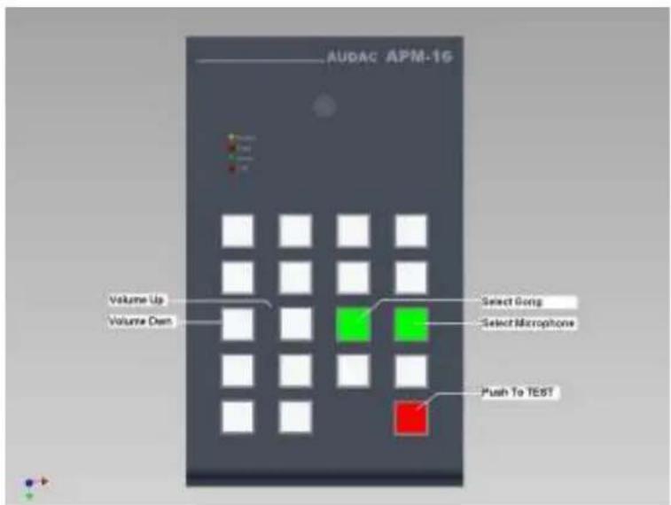
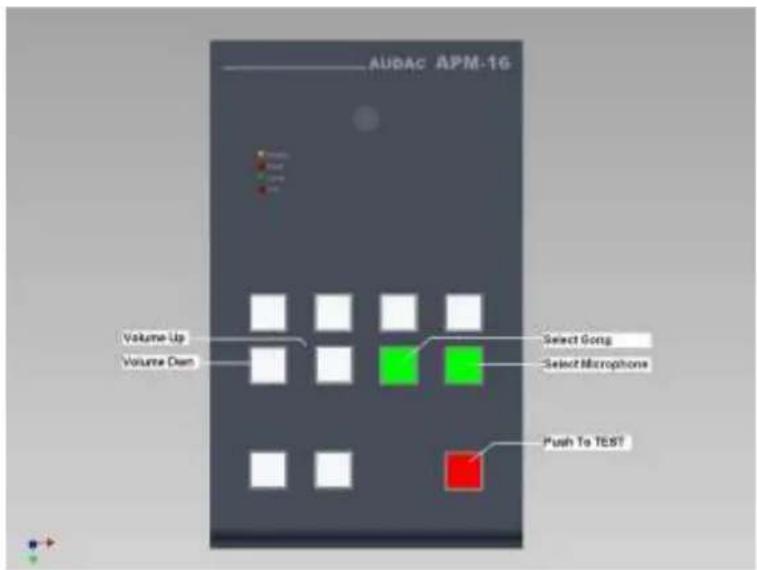
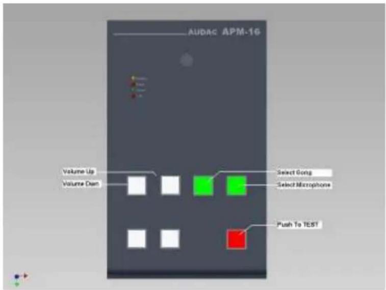
- Volume Up (mic. or gong): With this function button, you can increase the volume (microphone or gong) with steps of 3dB (256 steps).
- Volume Down (mic. or gong): With this function button, you can decrease the volume (microphone or gong) with steps of 3dB (256 steps).
- Select mic.: By pressing this button, you select the microphone to change its volume.
- Select gong: By pressing this button, you select the gong to change its volume.
The standard used bus protocol is RS-485, but with an extra plug-in card other bus standards are also available (e.g. LON,...).
ARU/AVD Receive/Switch module:
The Audac ARU/AVD Receive/Switch modules are designed for use with the AUDAC APM01/04/08/16 paging stations. The modules communicate over RS485 and have 4/8/16 relays for several switching tasks.
Following modules exist:
- ARU04: This module can switch between 2 signals (background music and Paging Microphone) and is equipped with 4 relays (4 different zones).
- ARU08: This module can switch between 2 signals (background music and Paging Microphone) and is equipped with 8 relays (8 different zones).
- ARU16: This module can switch between 2 signals (background music and Paging Microphone) and is equipped with 16 relays (16 different zones).
- AVD04: This module can switch a common signal (e.g. 24VDC) to 4 different outputs. (Activating emergency call relay, triggering power relays for curtains,...).
- AVD08: This module can switch a common signal (e.g. 24VDC) to 8 different outputs. (Activating emergency call relay, triggering power relays for curtains,...).
- AVD16: This module can switch a common signal (e.g. 24VDC) to 16 different outputs. (Activating emergency call relay, triggering power relays for curtains,...).
The ARU module:
This module was designed for switching between 2 signals (background music and Paging). There are 4, 8 and 16 channel modules.
The ARU module was made very flexible. For example: it's possible to use separate music sources for each zone, or to use 1 common music source for all Paging Zones. All combinations in between are possible. The connections which have to be made for this can be done in a very simple way by setting “jumpers”.
In case of large installations, the ARU modules can be placed in cascade and addressed by the Configuration Software.
The ARU module is suitable for mounting on a DIN-rail. On one side you have the “fixed connections” (e.g. Amplifiers, ...). On the other side you have the “field connections” (e.g. Loudspeaker cables, CAT5 bus cable,...). This way of working allows a quick, proper cabling of the system.
The AVD module:
This module was designed for switching 1 common signal to the output. There are 4, 8 and 16 channel modules.
The AVD module can be used for the following purposes:
- Activating the “Emergency Call” relay on a classic volume control. In this case, we’re going to switch 24V DC.
- Activating power relays or teleruptors to trigger e.g. window blinds, door contacts, ...
- Power on delay: In case of heavy equipment where the turn-on current is too large (e.g. 8 amplifiers of 4000 Watts), you can switch them on in cascade. The delay time is adjustable by a small trimmer on the AVD unit.
In case of large installations, the ARU modules can be placed in cascade and addressed by the Configuration Software.
The AVD module is suitable for mounting on a DIN-rail. On one side you have the “fixed connections” (e.g. Amplifiers, ...). On the other side you have the “field connections” (e.g. Loudspeaker cables, CAT5 bus cable,...). This way of working allows a quick, proper cabling of the system.
Accessories APM Paging Table
The APM 01/16 is standard equipped with a gooseneck microphone.
Other parts:
- Transparent bezels for buttons (APM16: 19pcs, APM08: 11pcs, APM04: 7pcs, APM01: 1pc).
- Windscreen for the microphone.
Chapter 1
Safety Requirements
The APM 01/04/08/16 can be configured by the free “AUDAC CONFIGURATION MANAGER” software tool. This must be done by a qualified person. Do not open the units, unless you are qualified to do so.
Remove the CAT5 cable before performing any servicing.
The ARU/AVD 04/08/16 contains several “jumpers” which can be set for a desired configuration. These settings may only be done by qualified people.
Switch the power off before changing any “jumpers”.

CAUTION - SERVICING
This unit contains no user serviceable parts. Refer all servicing to qualified service personnel. Do not perform any servicing unless you are qualified to do so.
Note
This product conforms to the following European Standards: EN 50081-1: 1992, EN 50082-1: 1992, EN 60065: 1994, EN 60849
Overview different APM models
APM 16:
text_image
AUDAC APM-16 Enable LED Peak LED Good LED Low LED 16 Zone Buttons Push to Select/ Deselect Zone Select ALL Clear ALL Push To TALKAPM 08:
text_image
AUDAC APM-08 Enable LED Peak LED Good LED Low LED 5 Zone Buttons Push to Select/ Deselect Zone Select ALL Clear ALL Push To TALKAPM 04:
text_image
AUDAC APM-04 Enable LED Peak LED Good LED Low LED 4 Zone buttons Push to Select/ Deselect Zone Select ALL Clear ALL Push To TALKAPM 01:
text_image
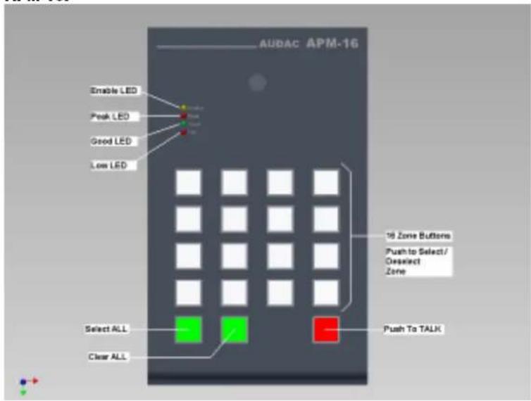
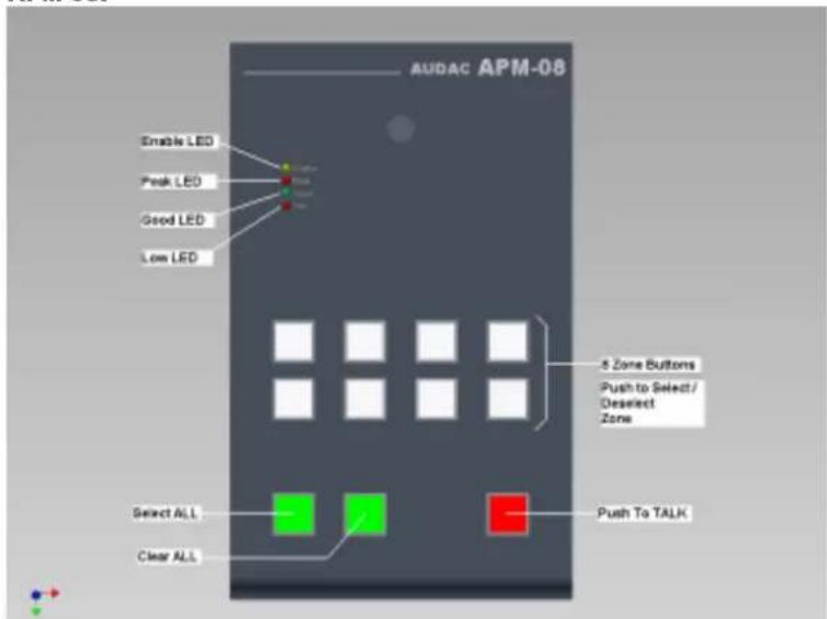
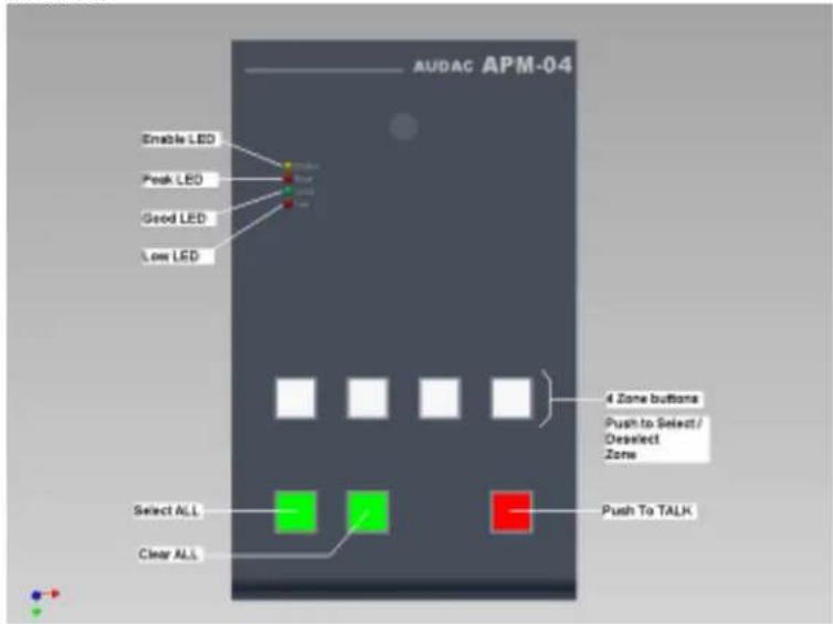
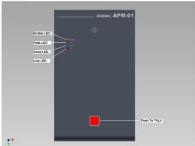
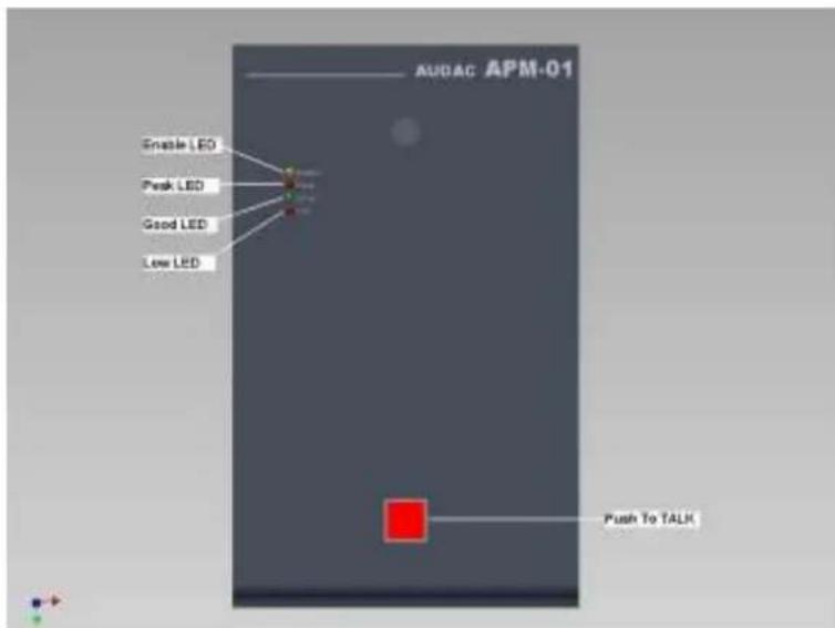
AUDAC APM-01 Enable LED Peak LED Good LED Low LED Push To TALKThe figures above present al modules with their standard functions behind the buttons.
There are 4 standard models :
- APM 16: Contains a 4x4 programmable button matrix and a row with basic functions. Following functions are standard on these buttons:
Zone 1 - 16, Select All, Clear All, Push to Talk.
- APM 08: Contains a 4x2 programmable button matrix and a row with basic functions. Following functions are standard on these buttons:
Zone 1 – 8, Select All, Clear All, Push to Talk.
- APM 04: Contains 4 programmable buttons and a row with basic functions. Following functions are standard on these buttons:
Zone 1 – 4, Select All, Clear All, Push to Talk.
- APM 01: Contains 1 single button: Push to Talk (General announcement).
It's possible to reprogram all function buttons. This can be done with the configuration software.
There are also 4 indication LED's with following functions:
Orange LED: Bus status (enable). Flashes when the gong is played.
Green LED: Voice level indication while speaking. The green LED means: Voice level is OK.
Red LED's: These LED's light up if the voice level is too low or too high.
In case of any malfunction (e.g. Microphone is broken), the green and red LED will start flashing. This way, you can always see if the Paging Table is functioning correctly.
Overview different ARU / AVD modules
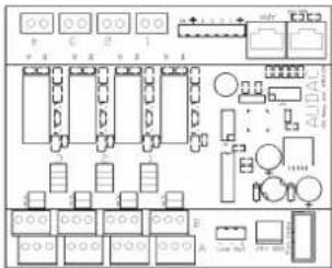
ARU04
text_image
Electrical circuit diagram with labeled components and connections, including switches, relays, and metersARU08

text_image
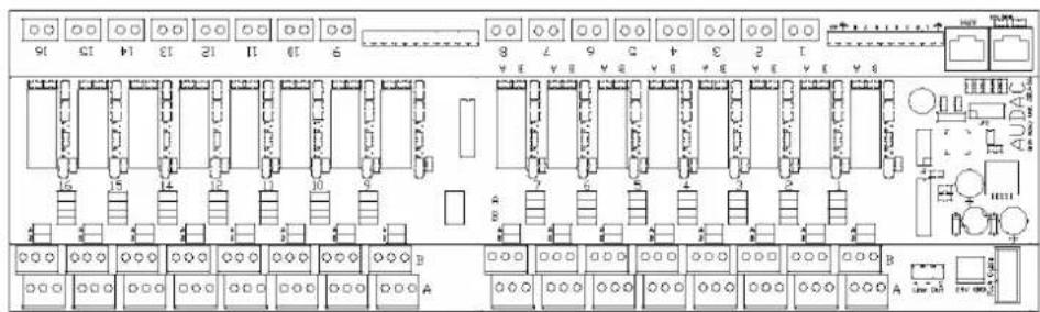
Electrical circuit diagram with labeled components and connections, including switches, relays, and audio outputARU16
text_image
Electrical schematic diagram with labeled components and connections, showing layout of switches, relays, and audio output.AVD04
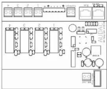
text_image
Electrical circuit diagram with labeled components and connections, including switches, relays, and audio outputAVD08
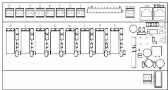
text_image
8 4 9 G F C 2 1 B Z 9 G F C 2 1 AUDIACAVD16
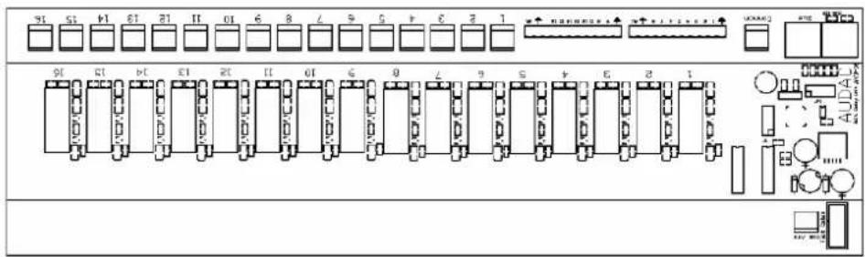
text_image
91 51 41 31 21 11 01 6 8 7 6 5 4 3 2 1 91 51 41 31 21 11 01 6 8 7 6 5 4 3 2 1 AUDAL SNDRJ-45 pin connections
The APM/ARU/AVD Series are connected by a CAT5 cable. The units need a 24V DC power supply. The 24V DC is connected to the ARU/AVD module. Every ARU/AVD module has 2 RJ45 sockets. By these sockets, the units are connected in a bus structure by a CAT5 cable. The connections are as described below:
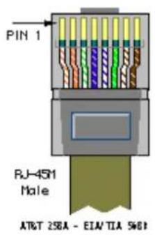
text_image
PIN 1 RJ-4SM Male AT&T 286A - EIA/TIA 546B| Pin 1 White-Orange LON A (optional) | ||
| Pin 2 Orange LON B (optional) | ||
| Pin 3 White-Green +24V DC | ||
| Pin 4 | Blue | RS485 A |
| Pin 5 | White-Blue | RS485 B |
| Pin 6 | Green | GND |
| Pin 7 | White-Brown | Audio S+ |
| Pin 8 | Brown | Audio S- |

ATTENTION
The Cat5 cabling must always be “straight”. In case of self made cabling, it must be done as described above, to make the system work properly. To easily create a bus structure, there are “ARJ-03 splitter” modules (AUDAC). These will be described later.
Power supply
Normally, the power supply must be connected with only one ARU-, AVD- or splitter module. The other modules of the paging network are fed through the CAT5 cable.
Maximum rated current
The power supply's maximum rated current must be higher than the sum of the currents of the connected modules. If the sum exceeds 2A, it's best to use an extra power supply instead of using a power supply with a larger maximum rated current.
For example: an APM module uses +/-300mA , an ARU/AVD/04/08 uses +/-200mA and an ARU16/AVD16 uses +/-400mA . Choosing the right 24V DC power supply: E.g.: We have 2x ARU08 modules, 1x AVD16 module and 3x paging stations. This means a total of 200 + 200 + 400 + 300 + 300 + 300 = 1.7 Ampere at 24V DC. In this case we recommend a power supply of at least 2A at 24V DC.
Voltage drop across the cable
In case of a large number of modules (ARU-, AVD modules and paging stations) and/or large cable distances, voltage loss across the CAT5 cable can occur. In this case some extra power supplies must be placed in the system. These power supplies can be connected to ARU-, AVD- or splitter modules.
Always make sure the power supply at the ARU-AVD modules and paging stations does not drop below 16V due to voltage drop across the cable.
A simplified calculation method can be used:
Allowable voltage drop across the cable: Vdrop = 8V
Average Cable resistance of UTP CAT5e cable: Rcable = 0.096 ohm/meter
Average current of a module: Iav = 0.3A
Number of modules: x
Cable length: L (in meters)
Simplified formula: Vdrop = L * Rcable * Iav * x
So maximum cable length L = Vdrop / (Rcable * Iav * x)
If we fill in the parameters, we get = 277 / x , with x being the number of connected modules.
For example: if we have 6 modules connected to one power supply, the maximum total cable length of the data bus is L = 277 / 6 = 46 meters.
Getting Started
APM:
When turning the power on, the APM paging station comes into its “USER MODE”. In this mode you have function buttons (in most cases Zone buttons, 4-8-16), one “Select All” button, one “Clear All” button and one “Talk” button.
When selecting a zone, the button will light up “green”. When pressing again, the green LED will go out. You can select all Zones by pressing “Select All” and deselect all made settings by pressing “Clear All”.
To make an announcement, you press the “Talk” button and keep it pressed down. This can only be done in case the audio bus is free (=not in use by another paging Station. The yellow LED may not light up).
Following actions will take place:
- All selected zones will be transmitted to the ARU/AVD receive units and the relays will switch.
- Next step is the playing of the "gong" signal. During this, the "enable" LED flashes.
- When the “gong” signal is terminated, the “enable” LED stops flashing, the “LOW” LED lights up and the microphone is turned on. From that moment, the announcement can begin. The best way to speak through the microphone is from a distance of ±5 cm, and with a voice level that makes the “green” LED (Level = GOOD) light up.
- To terminate the announcement, just release the "Talk" button.
- From that moment, you can change the selected zones for the next call.
The APM01 has just one “Talk” button, which is used to make a general announcement (All zones). It’s also possible to specify a number of zones. This must be done in the Configuration Manager Software Tool.
ARU:
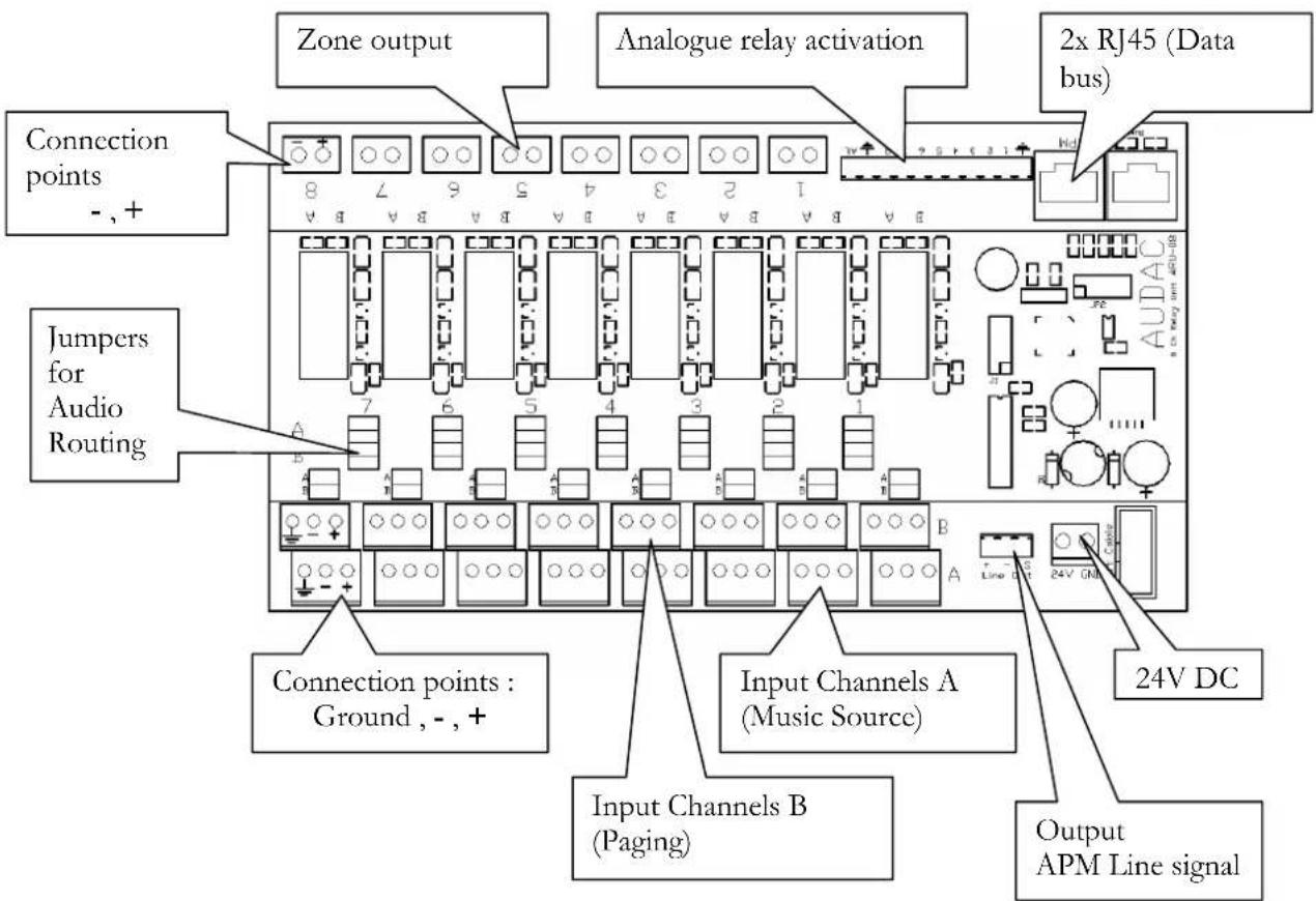
The figure below shows the meaning of the connections of an ARU08 module. These are the same for the ARU04 and ARU16 modules.
text_image
Zone output Analogue relay activation 2x RJ45 (Data bus) Connection points - , + Jumpers for Audio Routing Connection points : Ground , - , + Input Channels A (Music Source) Input Channels B (Paging) Output APM Line signalConnections ARU08
Zone output: This is the output to which signal A or B is switched for each zone. (The ground connection should be made at the connection points of Input Channel A or B.)
Input Channel A: This input is standard selected. It's meant for connecting the signal of a music source.
Input Channel B To this input channel, the signal of the Paging Table(s) must be connected. By disconnecting the power (e.g. Fault), this input will be passed through.
24V DC: The system needs 24V DC power. See part “Power supply and pin configuration” for more explanation.
Line output APM This is the line level signal of the paging table(s). This signal must go to an amplifier. There are different ways to do this (see next chapter).
Jumpers for Audio Routing With these jumpers you can easily make audio routings. This saves extra external cabling.
Analogue relay activation: This makes it possible to activate a relay simply by pulling a contact to the ground (e.g. with pushbutton,...).
2 x RJ45 (data bus): The data bus and DC power of all modules are distributed through the CAT5 cable. To guarantee proper operation, the cabling must be “Daisy-chain”. The front and the end of the bus must be terminated with a resistor (+-120 Ohm). This can be done on the last ARJ03-splitter module by setting a jumper (see further in this manual).
Jumper settings for audio routing
text_image
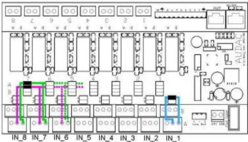
8 7 9 5 4 3 2 1 A B AUTAC IN_8 IN_7 IN_6 IN_5 IN_4 IN_3 IN_2 IN_1In this example 3 jumpers are set.
The jumper on the right side above input “IN_1” connects the left channel of “IN_1.A” to the right channel of “IN_1.A” (blue tracks). The second jumper can be used to connect the left channel of input channel IN_1.B to the right channel of IN_1.B. Input channel A and B each have their own jumper.
The two jumpers on the right side connect "IN_7.A.right" with "IN_8.A.right" (top jumper, green tracks) and "IN_7.A.left" with "IN_8.A.left" (second jumper, purple tracks). The third jumper can be used to connect "IN_7.B.right to "IN_8.B.right", and the fourth jumper can be used to connect "IN_7.B.left" with "IN_8.B.left". As you can see, it's possible to connect an input channel A or B to a previous and/or next input channel A or B.
Lots of combinations are possible. In the example above, the A input channels are used, but it's also possible to use the B input channels.
AVD:
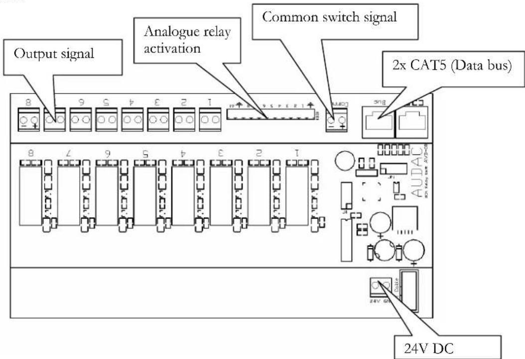
text_image
Output signal Analogue relay activation Common switch signal 2x CAT5 (Data bus) 24V DCConnections AVD08:
24V DC: The system needs 24V DC power. See part “Power supply and pin configuration” for more explanation.
Common switch signal To connect the common signal you want to switch (e.g. 24V DC or Paging signal).
Output Signal Where the common input signal is switched to.
Analogue relays activation: This makes it possible to activate relays by pulling the contact to ground (e.g. with push button).
2 x RJ45 (data bus): The data bus and DC power of all modules are distributed through the CAT5 cable. To guarantee proper operation, the cabling must be “Daisy-chain”. The front and end of the bus must be terminated with a resistor (+-120 Ohm). This can be done on the last RJ03-splitter module by setting a jumper (see further in this manual for more information).
text_image
Chapter 3Working principles of ARU/AVD in combination with APM
Following figures indicate the working principles of APM tables with ARU/AVD modules.
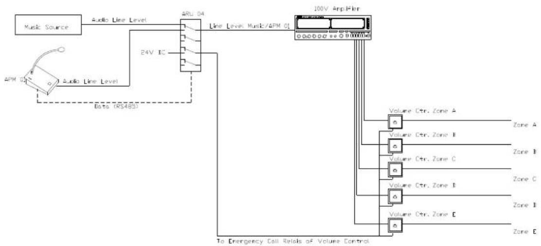
Possibility 1: APM01 directly on a priority input of a mixing amplifier
flowchart
graph TD
    A["Music Source"] --> B["Audio Line Level"]
    B --> C["24V IC"]
    C --> D["Line Level Music/APM 01"]
    D --> E["100V Applifier"]
    E --> F["Volume Ctr. Zone A"]
    E --> G["Volume Ctr. Zone B"]
    E --> H["Volume Ctr. Zone C"]
    E --> I["Volume Ctr. Zone D"]
    E --> J["Volume Ctr. Zone E"]
    E --> K["Volume Ctr. Zone F"]
    F --> L["Zone A"]
    G --> M["Zone B"]
    H --> N["Zone C"]
    I --> O["Zone D"]
    J --> P["Zone E"]
    K --> Q["Zone E"]
    R["Data (RS483)"] -.-> B
    S["To Emergency Call Relais of Volume Control"] --> E
The Paging Microphone input is connected to an override-input of a mixing amplifier. As option you can place an ARU or AVD module to activate Emergency Call relays, if there are volume controls in each room.
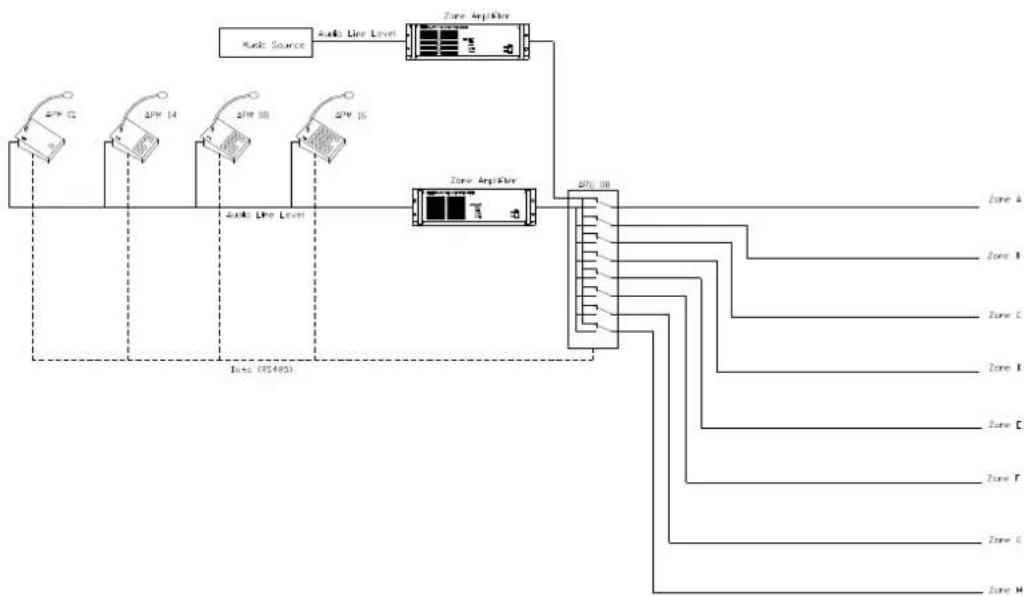
Possibility 2: in larger installations which have an amplifier for each zone (switching on Line Level)
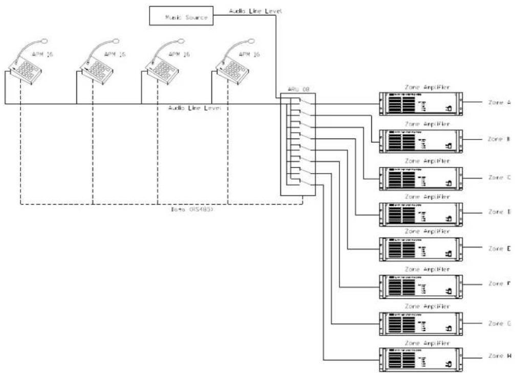
In this setup, the ARU module is placed in the Line Level circuit. You can make an announcement in every zone separately. With ARJ-03 splitter modules it's possible to connect more than 1 paging table to the system. Every paging table can have its own priority level.
If there is more than 1 ARU module used, the music sources must be connected to every ARU module. The paging signal is passed through the CAT5 cable and must be connected to Input B on the ARU module.
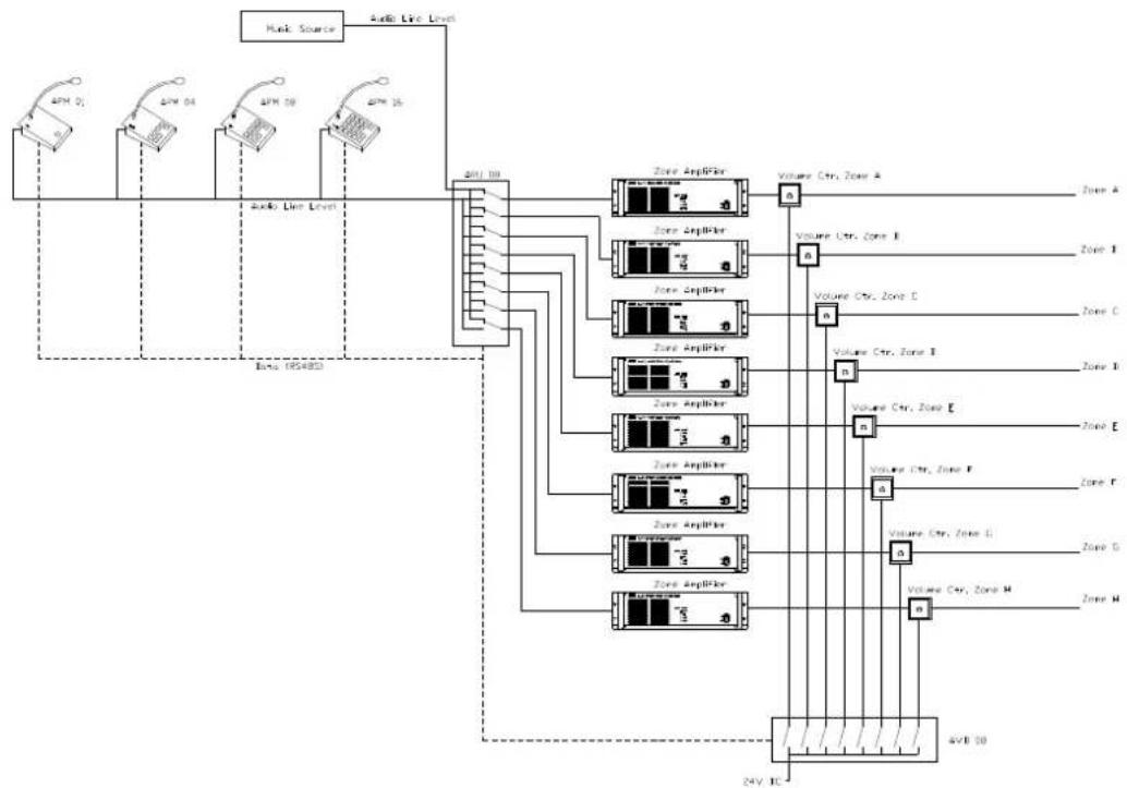
Possibility 3: switching on Line Level, including Emergency Call on volume controls
This is the same principle as in the previous case, except for the extra use of an AVD module to override the volume control in case of Emergency Call.
In this case the music can be regulated at low level, without influence on the paging signal.
flowchart
graph TD
    A["Audio Source"] --> B["24V IC"]
    C["Audio Line Level"] --> D["Zone Amplifier"]
    D --> E["Volume Ctr, Zone A"]
    D --> F["Volume Ctr, Zone B"]
    D --> G["Volume Ctr, Zone C"]
    D --> H["Volume Ctr, Zone D"]
    D --> I["Volume Ctr, Zone E"]
    D --> J["Volume Ctr, Zone F"]
    D --> K["Volume Ctr, Zone G"]
    D --> L["Volume Ctr, Zone H"]
    D --> M["Volume Ctr, Zone I"]
    D --> N["Volume Ctr, Zone J"]
    D --> O["Volume Ctr, Zone K"]
    D --> P["Volume Ctr, Zone L"]
    D --> Q["Volume Ctr, Zone M"]
    D --> R["Volume Ctr, Zone N"]
    D --> S["Volume Ctr, Zone O"]
Possibility 4: using two separate amplifiers for music and paging
flowchart
graph TD
    A["Audio Source"] --> B["Audio Line Level"]
    B --> C["Zone Amplifier"]
    C --> D["Output Zone A"]
    C --> E["Output Zone B"]
    C --> F["Output Zone C"]
    C --> G["Output Zone D"]
    C --> H["Output Zone E"]
    C --> I["Output Zone F"]
    C --> J["Output Zone G"]
    C --> K["Output Zone H"]
    style A fill:#f9f,stroke:#333
    style B fill:#ccf,stroke:#333
    style C fill:#cfc,stroke:#333
    style D fill:#fcc,stroke:#333
    style E fill:#fcc,stroke:#333
    style F fill:#fcc,stroke:#333
    style G fill:#fcc,stroke:#333
    style H fill:#fcc,stroke:#333
    style I fill:#fcc,stroke:#333
    style J fill:#fcc,stroke:#333
    style K fill:#fcc,stroke:#333
    style_L["Audio Line Level"] --> M["400 dB"]
    N["Audio Line Level"] --> O["400 dB"]
    P["Audio Line Level"] --> Q["400 dB"]
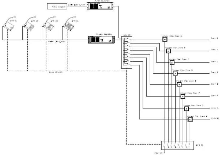
In this setup, you need an amplifier for the music signal and an amplifier for the paging signal. The volume between these two can be regulated separately. The power of the amplifier must be calculated on the total load of the system.
In this configuration, the great advantage is that there are only 2 amplifiers needed, even if there are more then 2 paging zones. The disadvantage is that the volume is equal for each room. This can be solved by placing volume controls in each room (with or without Emergency Call).
Possibility 5: switching on loudspeaker level, including Emergency Call on Volume Controls
flowchart
graph TD
    A["Audio Source"] --> B["Audio Live Level"]
    B --> C["Audio In Level"]
    C --> D["Flooding Amplifier"]
    D --> E["Zone 10"]
    D --> F["Zone 11"]
    D --> G["Zone 12"]
    D --> H["Zone 13"]
    D --> I["Zone 14"]
    D --> J["Zone 15"]
    D --> K["Zone 16"]
    D --> L["Zone 17"]
    D --> M["Zone 18"]
    D --> N["Zone 19"]
    D --> O["Zone 20"]
    D --> P["Zone 21"]
    D --> Q["Zone 22"]
    D --> R["Zone 23"]
    D --> S["Zone 24"]
    D --> T["Zone 25"]
    D --> U["Zone 26"]
    D --> V["Zone 27"]
    D --> W["Zone 28"]
    D --> X["Zone 29"]
    D --> Y["Zone 30"]
This is the same setup as the previous one, but with volume control for each zone. With an extra AVD unit, it's possible to switch the Emergency Call of the Volume Controls. In this case, you're switching 24V DC.
text_image
Chapter 4Wire up the System
The system uses an RS-485 bus protocol. For this reason, it's very important to avoid making a "STAR" structure in the cabling. In large systems it's also important to terminate the bus in a proper way. This can be done with an ARJ-03 module (explained further in this manual).
RS-485 is a differential bus structure, so cabling must be twisted pair (pairs of CAT5 are twisted). Data is the middle pair of the Cat5 cable (blue pair).
ARJ03 module:
This is a compact, cheap module which makes it possible to place more than one paging table on the bus. The module has a jumper for terminating the bus (120 Ohm resistor). The middle connector (marked: "To APM") is used to connect the paging table. The cable used to connect the paging table to the middle connector may not exceed 2m. If the cable is longer then 2m, a "star point" is created, so reflections on the data bus may occur and will result in signal and performance loss. An exception to this rule can be made when the paging table is connected at the end of the data bus, in other words: when there is no cable attached to the "Bus Out" connector.
The ARJ-03 module can be placed under a desk or in a cableway.
Following figure shows the top of the module:
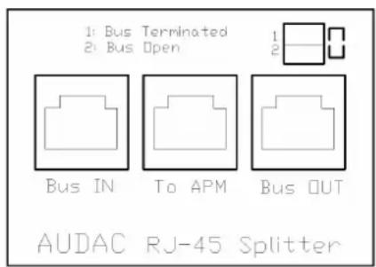
text_image
1: Bus Terminated 2: Bus Open Bus IN To APM Bus OUT AUDAC RJ-45 SplitterBUS STRUCTURE
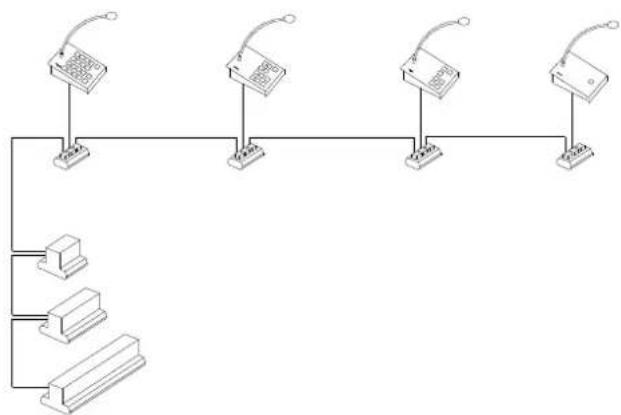
Following figure shows a correct example of cabling the system:
Wires connected to the paging tables are shorter than 2m, the total cable length of the data bus does not exceed 1000m.
flowchart
graph TD
    A["Device 1"] --> B["Switch"]
    C["Device 2"] --> D["Switch"]
    E["Device 3"] --> F["Switch"]
    G["Device 4"] --> H["Switch"]
    I["Device 5"] --> J["Switch"]
    K["Base Station"] --> L["Switch"]
    M["Base Station"] --> N["Switch"]
    O["Base Station"] --> P["Switch"]
ONE STARPOINT
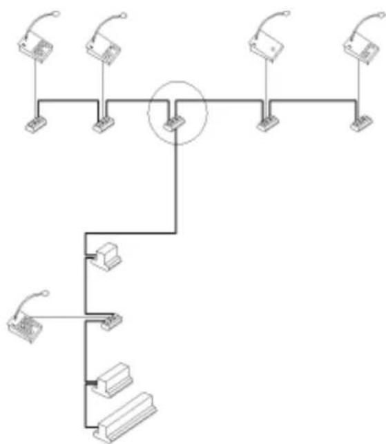
The figure below shows an example of a setup with one “star point” (T-junction). Avoid the use of one “star point”!
Wires connected to the paging tables are shorter than 2m, the total cable length of the data bus does not exceed 500m.
flowchart
graph TD
    A["Device 1"] --> B["Central Hub"]
    C["Device 2"] --> B
    D["Device 3"] --> B
    E["Device 4"] --> B
    F["Device 5"] --> B
    G["Device 6"] --> B
    H["Device 7"] --> B
    I["Device 8"] --> B
    J["Device 9"] --> B
    K["Device 10"] --> B
    L["Device 11"] --> B
    M["Device 12"] --> B
    N["Device 13"] --> B
    O["Device 14"] --> B
    P["Device 15"] --> B
    Q["Device 16"] --> B
    R["Device 17"] --> B
    S["Device 18"] --> B
    T["Device 19"] --> B
    U["Device 20"] --> B
    V["Device 21"] --> B
    W["Device 22"] --> B
    X["Device 23"] --> B
    Y["Device 24"] --> B
    Z["Device 25"] --> B
    AA["Device 26"] --> B
    AB["Device 27"] --> B
    AC["Device 28"] --> B
    AD["Device 29"] --> B
    AE["Device 30"] --> B
    AF["Device 31"] --> B
    AG["Device 32"] --> B
    AH["Device 33"] --> B
    AI["Device 34"] --> B
    AJ["Device 35"] --> B
    AK["Device 36"] --> B
    AL["Device 37"] --> B
    AM["Device 38"] --> B
    AN["Device 39"] --> B
    AO["Device 40"] --> B
    AP["Device 41"] --> B
    AQ["Device 42"] --> B
    AR["Device 43"] --> B
    AS["Device 44"] --> B
    AT["Device 45"] --> B
    AU["Device 46"] --> B
    AV["Device 47"] --> B
    AW["Device 48"] --> B
    AX["Device 49"] --> B
    AY["Device 50"] --> B
MULTIPLE "STAR POINTS"
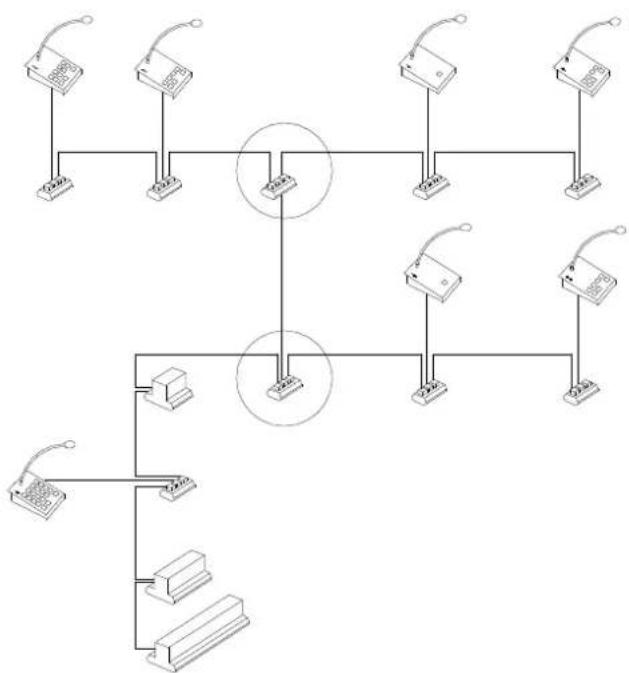
The figure below shows an example of a setup with multiple “star points”. Avoid the use of a multiple “star point” structure!
flowchart
graph TD
    A["Device 1"] --> B["Switch"]
    C["Device 2"] --> D["Switch"]
    E["Device 3"] --> F["Switch"]
    G["Device 4"] --> H["Switch"]
    I["Device 5"] --> J["Switch"]
    K["Device 6"] --> L["Switch"]
    M["Device 7"] --> N["Switch"]
    O["Device 8"] --> P["Switch"]
    Q["Device 9"] --> R["Switch"]
    S["Device 10"] --> T["Switch"]
    U["Device 11"] --> V["Switch"]
    W["Device 12"] --> X["Switch"]
    Y["Device 13"] --> Z["Switch"]
    AA["Device 14"] --> AB["Switch"]
    AC["Device 15"] --> AD["Switch"]
    AE["Device 16"] --> AF["Switch"]
    AG["Device 17"] --> AH["Switch"]
    AI["Device 18"] --> AJ["Switch"]
    AK["Device 19"] --> AL["Switch"]
    AM["Device 20"] --> AN["Switch"]
This is not a correct setup !!
text_image
Chapter 5Advanced operation APM
Activating “Setup Mode”: When you turn on the power (plug in CAT5Cable) while pressing the “Talk” Button, you activate “Setup Mode”. In this mode, the volume settings of the microphone and the gong can be adjusted.
Following figures give an overview of button-functions in "Setup Mode":
APM16:
text_image
AUDAC APM-16 Volume Up Volume Down Select Gong Select Microphone Push To TESTAPM08:
text_image
AUDAC APM-16 Volume-Up Volume Down Select Gong Select Microphone Push To TESTAPM04:
text_image
AUDAC APM-16 Volume Up Volume Down Select Gong Select Microphone Push To TESTAPM01:
text_image
AUDAC APM-01 Enable LED Peak LED Good LED Low LED Push To TALKWith an APM01, the volume settings are not possible.
All volume settings are standard regulated at proper levels. In normal circumstances, it won't be necessary to change them.
Configuration of the ARU/AVD modules
All AUDAC ARU and AVD modules can be configured with a free software configuration tool. This is necessary for addressing all modules, declaring button functions, ...
The “AUDAC CONFIGURATION SOFTWARE” tool can be downloaded for free in the download section of the AUDAC website http://www.audac.be. In the help-file of the program you’ll find a complete explanation of how the tool has to be used and the programming can be done. This tool is made by a “wizard” principle, so no necessary steps or settings can be overlooked.
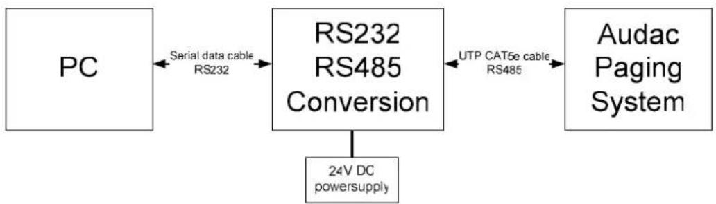
To be able to program an APM/ARU/AVD configuration, the configuration needs to be connected to a PC on which you have installed the Audac configuration software. The setup you have to make is described in the topic “Additional information APM/ARU/AVD”, section “Pinout RS485 Audac paging system for development purposes”.
Additional Information APM/ ARU/ AVD
PINOUT RS485 AUDAC PAGING SYSTEM FOR DEVELOPMENT PURPOSES
flowchart
graph LR
    PC["PC"] -->|Serial data cable RS232| RS232["RS232 RS485 Conversion"]
    RS232 -->|UTP CAT5e cable RS485| Audac["Paging System"]
    RS232 -->|24V DC powersupply| A["Ground"]
| RS485 UTP CAT5e cable | ||
| Pin number | Wire Color Con | ction |
| 1 orange / white NC | ||
| 2 orange NC | ||
| 3 green / white +24V DC | ||
| 4 | blue | RS485A |
| 5 | blue / white | RS485B |
| 6 | green | GND |
| 7 | brown / white | Audio Signal + |
| 8 | brown | Audio Signal - |
NC = not connected
Serial data cable depends on the RS232-RS485 conversion unit
CONDENSATOR MICROPHONE Audac CMS45
Small elegant electret microphone with gooseneck, with a 3/8" mounting screw.
Perfect for high definition speeches.
A cardioïde characteristic makes the microphone less sensitive for feedback.
Technical specifications microphone.
Microphone type electret
Dimensions ∅ 8 X 300 mm
Weight 100 gr.
Connections red= signal, ground = - white + power supply, ground - power supply
Supply Voltage 1,5 V max. 10 V
Dimensions APM console
WxLxH (mm) 120 x 192 x 50
Material Steel
Mechanical info ARU/AVD
Housing PVC, non-breakable
Fire Resistance V0(UL 94)
Max. temperature 60°
Color Green
U-profile PVC, non-breakable
Color Transparent
Max. temperature 55°
Side plates Polyamide PA
Fire resistance V0(UL 94)
Color Green
Dimensions ARU/AVD
ARU4/ AVD4 (WxHxL) 137 x 98 x 126
ARU8/ AVD8 (WxHxL) 207 x 98 x 126
ARU16/ AVD8 (WxHxL) 380 x 98 x 126
ARJ3 (WxHxL) 82 x 30 x 45
APM1/4/8/16 (WxHxL) 120 x 55 x 195
Technical specs
Power 24V DC
Data bus protocol RS-485
Bus cabling CAT5