
ANI44 - Network card Audac - Free user manual and instructions
Find the device manual for free ANI44 Audac in PDF.


| Product Type | Network Audio Card |
| Model | ANI44 |
| Brand | Audac |
| Audio Channels | 4 (4 inputs / 4 outputs) |
| Network Interface | Ethernet 10/100/1000 Mbps |
| Audio Inputs | 4 x Balanced XLR |
| Audio Outputs | 4 x Balanced XLR |
| Power Supply | PoE (IEEE 802.3af) or 48 V DC |
| Dimensions (W x D x H) | 48.3 x 10.5 x 4.5 cm |
| Weight | 1.5 kg |
| Supported Audio Formats | PCM up to 24-bit / 96 kHz |
| Control Interface | Web-based GUI |
| LED Indicators | Power, Link, Signal Presence |
| Operating Temperature | 0°C to 40°C |
| Storage Temperature | -20°C to 60°C |
| Housing Material | Metal chassis |
| Compliance | CE, RoHS |
| Maintenance | Clean with dry, soft cloth; avoid liquids |
| Safety | Use only supplied power adapter; keep away from moisture |
| Spare Parts & Repairability | No user-serviceable parts inside; contact qualified service |
Frequently Asked Questions - ANI44 Audac
User questions about ANI44 Audac
0 question about this device. Answer the ones you know or ask your own.
Ask a new question about this device
Download the instructions for your Network card in PDF format for free! Find your manual ANI44 - Audac and take your electronic device back in hand. On this page are published all the documents necessary for the use of your device. ANI44 by Audac.
USER MANUAL ANI44 Audac
The ANIxx are Dante audio network interfaces for use with WaveDynamics™ supporting amplifiers, supporting two (ANI22) or four (ANI44) networked audio channels. The installation of this optional interfaces allows these amplifiers to be integrated into any DANTE enabled AV network and flawlessly transfer digital audio with any compatible product on the market, ranging from music sources to microphone systems, mixers, and many more.
These interfaces come delivered as a complete installation kit, including all required accessories for installation into the WaveDynamics™ amplifier chassis.
INSTALLATION PRECAUTIONS

The installation of the ANI module may only be performed by qualified technicians.
Incorrect installation can lead to permanent damage or incorrect functioning of the equipment.
Packaging contents
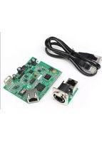
- 1x ANIxx main interface board
- 1x ANIxx ethernet connection board
-
1x ANIxx ethernet connection cable
– Required installation accessories: -
2x Nylon snap-in spacer
- 1x M3 spacer
- 1x Spring washer
- 1x M3 nut
- 2x Cable tie
– USB memory drive (containing software and instructions)
Instructions
Mounting and connecting
Step 1:
ATTENTION

Make sure the amplifier is powered off and the power inlet is disconnected from the mains power before the enclosure is opened.
Step 2:
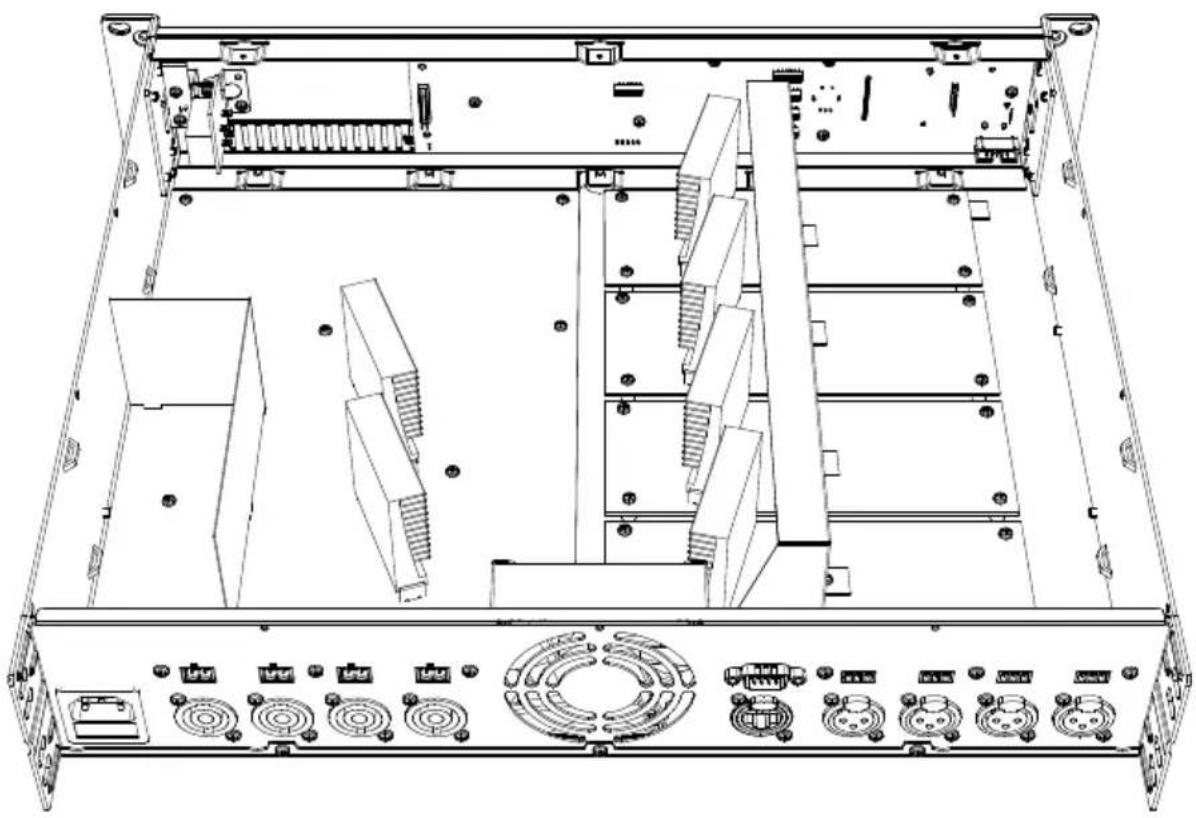
Open the amplifiers' enclosure by carefully removing the screws from the top panel of the device, and lifting it.
natural_image
Technical line drawing of a server rack with multiple drive bays and ventilation fans (no text or labels)Step 3:
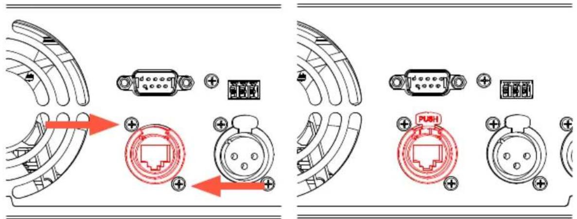
3.1. Remove the latch from the Ethercon compatible connector on the connection board by putting a flat screwdriver underneath the clip and pulling back screwdriver and latch together. This will simplify the assembly of the ethernet connection board in the back of the unit.

natural_image
Illustration of four different types of mechanical components with red arrows indicating assembly or transformation (no text or symbols present)3.2. Remove the cover plate at the 'EXPANSION' hole on the back of the amplifier. The ethernet connection board of the ANIxx shall be installed on this position.
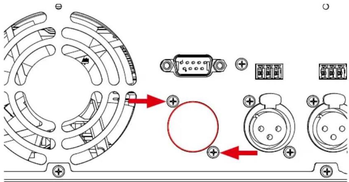
3.3. Insert the ethernet connection board from the inner side of the amplifier to the 'EXPANSION' hole, and fix it by inserting and tightening the two supplied screws. The latch removed from the connector in step 3.1 can now get inserted to the connector again by simply inserting and pushing it into the right position.

natural_image
Technical line drawing of an internal electronic device with a fan and connector (no text or symbols)REMARK
Detaching the upper input board (containing terminal block and RS-232 sockets) may facilitate the installation. Make sure it is well fastened again afterwards.
Step 4:
Once the Ethernet connection PCB is correctly installed, the supplied ethernet connection cable shall be plugged to the RJ45 connection socket in the inner side of the ethernet connection board.

natural_image
Technical line drawing of an internal computer drive with fan, cooling unit, and ventilation slots (no text or labels)Step 5:
Mount the ANIxx main interface board into the amplifier:
5.1. Remove the screw on the most left side of the front display board of the amplifier and replace it by the supplied M3 spacer.

natural_image
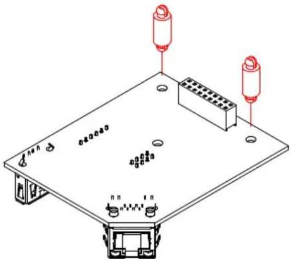
Technical line drawing of a mechanical assembly with two views showing internal components and red arrows indicating directional indicators (no text or symbols present)5.2. Insert both supplied nylon snap-in spaces into the appropriate holes in the ANIxx main interface board as indicated in the below image.
natural_image
Isometric technical diagram of an electronic device with two red cylindrical components and mounting holes (no text or symbols)5.3. Fix the ANIxx main interface board into the amplifier by simply clicking it onto the front display board using both snap-in spacers. Make sure the female pin-header on the main interface board is well positioned and matching the male counterpart on the front display board of the amplifier. Once positioned correctly, securing can be done by putting the supplied washer and nut and tightening it.

natural_image
Technical line drawing of a mechanical assembly with internal components and red-labeled connectors (no text or symbols)Step 6:
Connect the cable from the ethernet connection board to the RJ45 jack on the main interface board and position the cable as indicated in the below image. Correct positioning of the cable is important to avoid touching heating amplifier parts and to avoid obstruction of the internal air-flow of the device. The networking cable shall be fixed to the internal provided tabs using the supplied cable tie's.

natural_image
Technical line drawing of a server rack with multiple panels and connectors, showing internal components and mounting points (no text or symbols)Step 7:
Double check whether all internal wires are well connected and well positioned. After all connections are successfully made, the top cover of the amplifier can be re-fitted and fixed using the original screws.
Step 8:
To guarantee the correct functioning of the amplifier with the installed ANIxx Dante network audio interface, verify whether the current running software version fully supports this interfaces functions.
For SMA/SMQ amplifiers, software shall be version 1.17 or higher
The software version of your amplifier is shown on the front LCD display when powering on the amplifier. When it is not Dante ready, you can update your amplifier with supplied USB drive. Connect it at the front of your amplifier and update process will start automatically.
Result:
Your amplifier is now equipped with a Dante network audio interface, allowing new networked audio possibilities.
For more information about the functions, the connections or Dante in general, refer to the quick start guide or Dante controller user guide.
Additional information
Technical specifications
Number of inputs ANI22 2
ANI44 4
Number of outputs ANI22 2
ANI44 4
Communication Protocol Audinate DANTE
Sampling frequency 48 kHz
Sampling bit depth
Latency 2 \~ 5 ms
Connection Ethercon compatible RJ45 connector
Network specification Standard 100 Mbit or 1 Gbit network
Mounting Integration in amplifie
Power consumption 1.5 Watt
Weight 0.090 Kg
Compatible devices (implementation) ANI22 SMA Series WaveDynamics™ amplifiers
ANI44 SMQ Series WaveDynami
Protocol (DANTE) compatible devices https://www.audinate.com/products/dante-enabled
Notes
Notes
Notes
Brand : Audac
Model : ANI44
Category : Network card