4101-MB-PBS - Uncategorized Moxa - Free user manual and instructions
Find the device manual for free 4101-MB-PBS Moxa in PDF.


User questions about 4101-MB-PBS Moxa
0 question about this device. Answer the ones you know or ask your own.
Ask a new question about this device
Download the instructions for your Uncategorized in PDF format for free! Find your manual 4101-MB-PBS - Moxa and take your electronic device back in hand. On this page are published all the documents necessary for the use of your device. 4101-MB-PBS by Moxa.
USER MANUAL 4101-MB-PBS Moxa
MGate 4101-MB-PBS Modbus Serial-to-PROFIBUS Slave Gateway User's Manual
Edition 4.0, March 2016
www.moxa.com/product
MGate 4101-MB-PBS
Modbus Serial-to-PROFI BUS
Slave Gateway User's Manual
The software described in this manual is furnished under a license agreement and may be used only in accordance with the terms of that agreement.
Copyright Notice
© 2016 Moxa Inc. All rights reserved.
Trademarks
The MOXA logo is a registered trademark of Moxa Inc.
All other trademarks or registered marks in this manual belong to their respective manufacturers.
Disclaimer
Information in this document is subject to change without notice and does not represent a commitment on the part of Moxa.
Moxa provides this document as is, without warranty of any kind, either expressed or implied, including, but not limited to, its particular purpose. Moxa reserves the right to make improvements and/or changes to this manual, or to the products and/or the programs described in this manual, at any time.
Information provided in this manual is intended to be accurate and reliable. However, Moxa assumes no responsibility for its use, or for any infringements on the rights of third parties that may result from its use.
This product might include unintentional technical or typographical errors. Changes are periodically made to the information herein to correct such errors, and these changes are incorporated into new editions of the publication.
Technical Support Contact Information
www.moxa.com/support
Moxa Americas
Toll-free: 1-888-669-2872
Tel: +1-714-528-6777
Fax: +1-714-528-6778
Moxa Europe
Tel: +49-89-3 70 03 99-0
Fax: +49-89-3 70 03 99-99
Moxa India
Tel: +91-80-4172-9088
Fax: +91-80-4132-1045
Moxa China (Shanghai office)
Toll-free: 800-820-5036
Tel: +86-21-5258-9955
Fax: +86-21-5258-5505
Moxa Asia-Pacific
Product Features 1-2
2. Getting Started 2-1
Connecting Power 2-2
Connecting PROFIBUS Devices 2-2
Connecting Modbus Serial Devices 2-2
Connecting to a Host via Serial Console Cable 2-2
3. Hardware 3-1
Power Input and Relay Output Pinouts 3-2
LED Indicators....3-2
Dimensions 3-2
Pin Assignments 3-3
Mounting the Unit 3-4
Specifications....3-4
Adjustable Pull High/Low Resistors for the Modbus Port (P1) in RS-485 Mode....3-6
Reset Button 3-7
Rotary Switch....3-7
4. Configuration 4-1
Installing the Software 4-2
Starting MGate Manager 4-5
Connecting to the Unit....4-7
Modifying the Configuration 4-9
Configure Device 4-10
Configure Modbus Settings 4-11
Set Up PROFIBUS 4-12
IO Mapping Setup 4-13
Auto Mapping 4-18
QuickLink 4-19
Paging 4-21
Load Default 4-23
Monitoring Modbus Activity 4-24
Diagnose 4-27
Upgrading Firmware 4-29
Import/Export 4-30
Off-Line Configuration 4-34
A. Quick Configuration ...... A-1
Typical Applications....A-2
Quick Configuration Steps....A-3
PROFIBUS Overview....A-3
Modbus Overview ...... A-4
Diagnose Packet Format A-6
Welcome to the MGate 4101-MB-PBS line of Modbus to PROFIBUS gateways. All models feature easy protocol conversion from Modbus to PROFIBUS, and RS-232/422/485 port for Modbus communication.
This chapter is an introduction to the MGate 4101-MB-PBS and includes the following sections:
Overview
□ Package Checklist
□ Product Features
Overview
The MGate 4101-MB-PBS is a line of protocol gateways that provides users with the following features:
Protocol conversion between Modbus and PROFIBUS
MGate 4101-MB-PBS series products can be used to connect Modbus devices and PROFIBUS devices to provide PLCs (ex. Siemens S400, S300) with remote maintenance capability.
Windows utilities for easy setup and traffic monitoring
A Windows utility is provided to make configuration and operation of the MGate 4101-MB-PBS as easy as possible. The utility uses serial console port to connect MGate 4101-MB-PBS unit. Besides, Wizard functions can help you finish configuration in only several minutes by automatic commands detection and automatic memory mapping.
Package Checklist
All models of the MGate 4101-MB-PBS series are shipped with the following items:
Standard Accessories:
• 1 MGate 4101-MB-PBS Modbus Serial-to-PROFIBUS Slave Gateway.
• Documentation & Software CD.
• Quick Installation Guide (printed).
• Product warranty statement.
• RJ45 to DB9 cable (for console use)
Optional Accessories:
- DR-4524: 45W/2A DIN-rail 24 VDC power supply with universal 85 to 264 VAC input.
- DR-75-24: 75W/3.2A DIN-rail 24 VDC power supply with universal 85 to 264 VAC input.
- DR-120-24: 120W/5A DIN-rail 24 VDC power supply with 88 to 132 VAC/176 to 264 VAC input by switch.
• WK-36-02: Wall mounting kit
• Mini DB9F-to-TB Adaptor: DB9 female to terminal block adapter
Note: Notify your sales representative if any of the above items is missing or damaged.
Product Features
• Automatic Windows configuration utility
- Redundant dual DC power inputs
• Enhanced surge protection for serial and power
• 2 kV isolation for serial signals (-1 model only)
• PROFIBUS connector to connect the gateway to the field bus
• Power-off warning by relay output
• Software-selectable RS-232/422/485 communication
The following topics are covered in this chapter:
□ Connecting Power
□ Connecting PROFIBUS Devices
□ Connecting Modbus Serial Devices
□ Connecting to a Host via Serial Console Cable
Connecting Power
The unit can be powered using the AC adaptor or by connecting a power source to the terminal block, depending on the model. The following instructions are for the AC adaptor:
- Plug the connector of the power adapter into the DC-IN jack on the back of the unit.
- Plug the power adapter into an electrical outlet.
Follow these instructions to connect a power source to the terminal block:
- Loosen or remove the screws on the terminal block.
- Connect the 12-48 VDC power line to the terminal block.
- Tighten the connections using the screws on the terminal block.
Note that the unit does not have an on/off switch. It automatically turns on when it receives power. The PWR LED on the top panel will glow to indicate that the unit is receiving power. For power terminal block pin assignments, please refer to the hardware reference chapter for your model.
Connecting PROFIBUS Devices
The unit's PROFIBUS port(s) are located on the front panel. Use a PROFIBUS cable to directly connect the unit to a PROFIBUS PLC or other PROFIBUS master.
For the PROFIBUS port pin assignments, please refer to Chapter 3. This information can then be used to construct your own PROFIBUS cable.
Connecting Modbus Serial Devices
The unit's Modbus port(s) are located on the front panel. Use a Modbus cable to directly connect the unit to a Modbus RTU/ASCII device.
For the Modbus port pin assignments, please refer to Chapter 3. This information can then be used to construct your own Modbus cable.
Connecting to a Host via Serial Console Cable
A RS-232 serial console port is located on the unit's front panel. This port is used for console configuration via a CBL-RJ45-F9-150 RJ-45-to-DB9 cable.
For normal operation, use a standard straight-through RS-232 serial cable to connect the unit to your COM port. You connect the unit directly to a PC. Besides, use a serial cable to connect the unit to your PC's serial connector.
The Tx/Rx LED of the console port will light up to indicate serial connection status when data is communicated with each other.
The following topics are covered in this chapter:
☐ Power Input and Relay Output Pinouts
□ LED Indicators
□ Dimensions
□ Pin Assignments
□ Mounting the Unit
Specifications
□ Reset Button
□ Rotary Switch
☐ Adjustable Pull High/ Low Resistors for the Modbus Port (P1) in RS-485 Mode
Power Input and Relay Output Pinouts
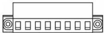
 | V2+ V2- | 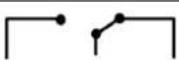 | V1+ V1- | ||||
| Shielded Ground | DC Power Input 2 | DC Power Input 2 | N.O. | Common N.C. | DC Power Input 1 | DC Power Input 1 | |
LED Indicators
| LED Color Function | ||
| PWR1 | Green Power is on. | |
| Off Power is off. | ||
| PWR2 | Green Power is on. | |
| Off Power is off. | ||
| Ready | Green Gateway is operational. | |
| Red Gateway has wrong settings. | ||
| Off | Power is off or fault condition exists. | |
| P1 Tx/Rx (Modbus Serial) | Green Serial device is transmitting data. | |
| Orange Serial device is receiving data. | ||
| Off | No data is flowing to or from the serial port. | |
| P2 Status (PROFIBUS) | Green | Steady: Gateway is waiting for data exchanging.Blinking: Data is exchanging. |
| Orange | Steady: Error in Configuration.Blinking: Error in Parameter data | |
| Off PROFIBUS offline or Slave ID wrong. | ||
Dimensions
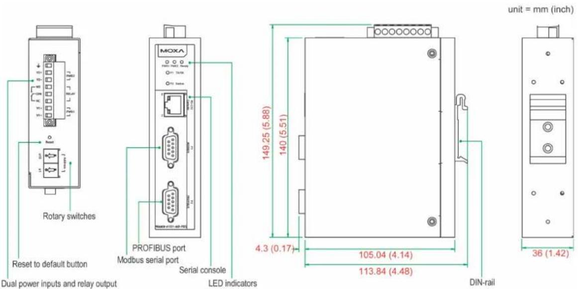
text_image
Rotary switches Reset to default button PROFIBUS port Modbus serial port Serial console LED indicators 149.25 (5.88) 140 (5.51) 4.3 (0.17) 105.04 (4.14) 113.84 (4.48) 36 (1.42) unit = mm (inch)Pin Assignments
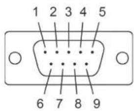
Modbus P1 Pin Assignment
The MGate 4101-MB-PBS series use DB9 (male) serial port to connect to Modbus devices.
| Pin | RS-232 | RS-422/RS-485 (4W) | RS-485 (2W) |
| 1 | DCD TxD-(A) --- | ||
| 2 | RXD TxD+(B) --- | ||
| 3 | TXD RxD+(B) Data+(B) | ||
| 4 | DTR | RxD-(A) | Data-(A) |
| 5 | GND GND GND | ||
| 6 | DSR | --- | --- |
| 7 | RTS | --- | --- |
| 8 | CTS | --- | --- |
| 9 | --- | --- | --- |
text_image
1 2 3 4 5 6 7 8 9PROFIBUS P2 Pin Assignment
The MGate 4101-MB-PBS series use DB9 (female) serial port to connect to PROFIBUS devices.
| PIN | Signal Name |
| 1 | N.C. |
| 2 | N.C. |
| 3 | PROFIBUS D+ |
| 4 | RTS |
| 5 | Signal common |
| 6 | 5V |
| 7 | N.C. |
| 8 | PROFIBUS D- |
| 9 | N.C. |
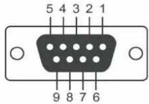
text_image
5 4 3 2 1 9 8 7 6Console (RS-232) Pin Assignment
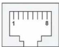
The MGate 4101-MB-PBS series use RJ45 serial port to connect to PC to configure device.
| PIN | RS-232 |
| 1 | DTR |
| 2 | RTS |
| 3 GND | |
| 4 | TXD |
| 5 | RXD |
| 6 DCD | |
| 7 | CTS |
| 8 | DTR |
Mounting the Unit
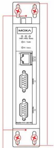
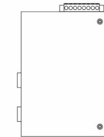
The unit can be mounted on the wall or on a DIN-rail. The MGate 4101-MB-PBS/4101I-MB-PBS series is designed to be attached to a DIN-rail or mounted on a wall. For DIN-rail mounting, push down the spring and properly attach it to the DIN-rail until it "snaps" into place. For wall mounting, install the wall mount kit (optional) first, and then screw the device onto the wall. The following figure illustrates the two mounting options:
Wall-Mount Installation
text_image
MOXA PRES: PRES2 Equity P1: T5/68 P2 Status 3000V 100 V 3000V 70 V 100V 20 V MOXA#4107-402-PDSDIN-Rail Installation
natural_image
Pure electrical circuit lines without any symbols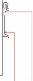
natural_image
Pure architectural line drawing of a vertical wall and right-angle bracket (no text or symbols)Step 2: Screw onto wall
Step 1: Push down the spring
Step 2: Click onto DIN rail
Step 1: Install wall-mount kit
Specifications
Power Input
Input Voltage: 12 to 48 VDC
Connector: 8-pin terminal block (GND, V1+, V1-, Relay NO, Common, Relay NC, V2+, V2-), screw mounting
Modbus Serial Interface
Protocol: Modbus ASCII/RTU, Master/Slave
Number of Ports: 1
Serial Standards: RS-232/422/485, software selectable
Data Bits: 7, 8
Stop Bits: 1, 2
Parity: None, Even, Odd, Space, Mark
Flow Control: RTS/CTS, XON/XOFF
Baudrate: 50 bps to 921.6 kbps
Connector: DB9 male
Serial Line Protection ESD: 15 kV protection for all signals
Isolation: 2 kV protection (MGate 4101I-MB-PBS only)
RS-485 Data Direction Control: ADDC® (automatic data direction control)
Pull High/ Low Resistor for RS-485: 1 kΩ, 150 KΩ (switchable)
Terminal Resister: 120 Ω for RS-485
Modbus Function: 1, 2, 3, 4, 5, 6, 15, 16
Modbus Serial Signals
RS-232: TxD, RxD, RTS, CTS, DTR, DSR, DCD, GND
RS-422: Tx+, Tx-, Rx+, Rx-, GND
RS-485-4w: Tx+, Tx-, Rx+, Rx-, GND
RS-485-2w: Data+, Data-, GND
PROFI BUS Interface
Protocol: PROFIBUS DP-V0 Slave
Data Rate: 9600 bps, 19.2, 93.75, 187.5, 500 kbps, 1.5, 3, 6 and 12 Mbps
Connector: DB9 female
Isolation: Built-in 2 kV
DIP Switch: for Termination
Rotary Switch: PROFIBUS address 0\~99 (addresses 100 to 125 supported by SW)
Console Interface RJ45 to DB9 cable
Console Interface
RJ45 to DB9 cable
Utility
Driver Support: Windows 2000/XP/2003/Vista/2008/7/8/8.1 x86/x64, 2012/2012 R2
Physical Characteristics
Housing : Metal, IP30 protection
Dimensions: 36 x 105 x 140 mm (1.42 x 4.13 x 5.51 in)
Environmental Limits
Operating Temperature:
Standard Temp. Models: 0 to 60°C (32 to 140°F)
Wide Temp. Models: -40 to 75°C (-40 to 167°F)
Operating Humidity: 5 to 95% RH
Storage Temperature: -40 to 85°C (-40 to 185°F)
Standards and Certifications
Safety: UL 60950-1, EN 60950-1
Hazardous Location: UL/cUL Class 1 Division 2 Groups A/B/C/D, ATEX Zone 2, IECEx
EMC: CE, FCC
EMI : EN 55022 Class A, FCC Part 15 Subpart B Class A
EMS: EN 55024,
EN 61000-4-2 (ESD) Level 3,
EN 61000-4-3 (RS) Level 2,
EN 61000-4-4 (EFT) Level 3,
EN 61000-4-5 (Surge) Level 3,
EN 61000-4-6 (CS) Level 2,
EN 61000-4-8 (PFMF) Level 1
Shock: IEC 60068-2-27
Freefall: IEC 60068-2-32
Vibration: IEC 60068-2-6
Reliability
Alert Tools: Built-in buzzer and RTC (real-time clock)
MTBF: 513,139 hours
Warranty
Warranty Period: 5 years
Details: See www.moxa.com/warranty
Adjustable Pull High/ Low Resistors for the Modbus Port (P1) in RS-485 Mode
natural_image
Pure electrical circuit lines without any symbolsDefault
| SW | 1 2 3 | ||
| Pull High | Pull Low | Terminator | |
| ON | 1 KΩ | 1 KΩ | 120 Ω |
| OFF | 150 KΩ | 150 KΩ | - |
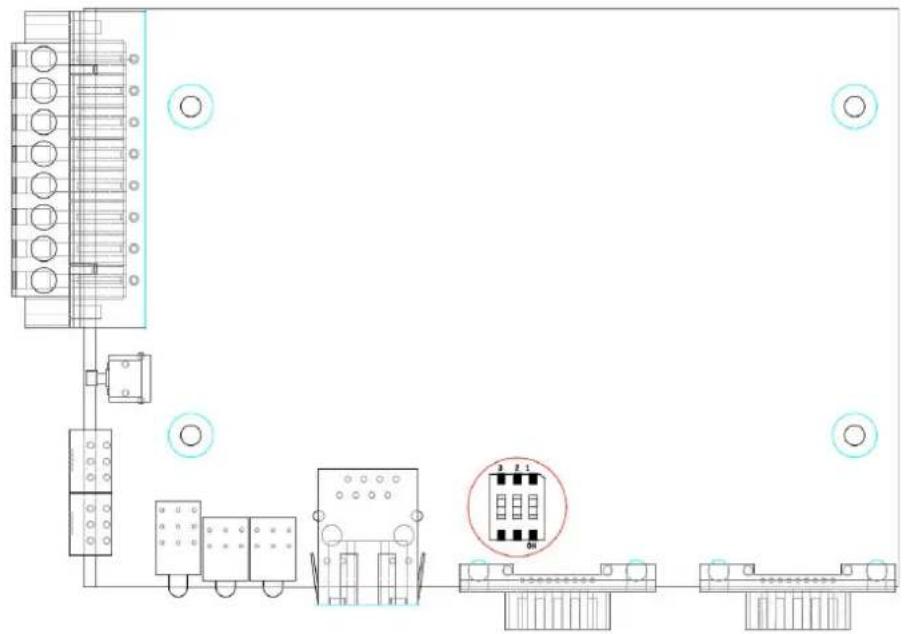
In some critical environments, you may need to add termination resistors to prevent the reflection of serial signals. When using termination resistors, it is important to set the pull high/low resistors correctly so that the electrical signal is not corrupted. The MGate uses jumper settings or DIP switches to set the pull high/low resistor values for each serial port.
To set the pull high/low resistors to 150 KΩ, make sure that the two jumpers assigned to the serial port are not shorted by jumper caps. This is the default setting.
To set the pull high/low resistors to 1 KΩ, make sure that the two jumpers assigned to the serial port are shorted by jumper caps.

ATTENTION
Do not use the 1 KΩ setting on the MGate when using the RS232 interface. Doing so will degrade the RS-232 signals and shorten the maximum allowed communication distance.
Reset Button
text_image
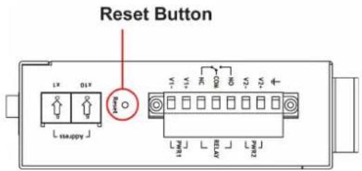
Reset Button L1X 01X L1X happy J + - + - - - - - - - M1M 1M 2M 3M 4M 5M 6M 7M 8M 9M 10M 11M 12M 13M 14M 15M 16M 17M 18M 19M 20M 21M 22M 23M 24M 25M 26M 27M 28M 29M 30M 31M 32M 33M 34M 35M 36M 37M 38M 39M 40M 41M 42M 43M 44M 45M 46M 47M 48M 49M 50M 51M 52M 53M 54M 55M 56M 57M 58M 59M 60M 61M 62M 63M 64M 65M 66M 67M 68M 69M 70M 71M 72M 73M 74M 75M 76M 77M 78M 79M 80M 81M 82M 83M 84M 85M 86M 87M 88M 89M 90M 91M 92M 93M 94M 95M 96M 97M 98M 99MTo reset the MGate to the factory default settings, hold down the reset button for about 5 seconds. The MGate will restart and be reset to factory default settings.
Rotary Switch
text_image
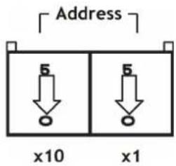
Address 5 5 x10 x1Before communication, you must assign a slave ID to the PROFIBUS slave, If you would like to assign an address between 0 to 99, you need to change the rotary switch to the desired address. If you would like to assign an address which is over 99, you must set it in the MGate utility.
The following topics are covered in this chapter:
□ Installing the Software
□ Starting MGate Manager
□ Connecting to the Unit
□ Modifying the Configuration
Configure Device
Configure Modbus Settings
Set Up PROFIBUS
IO Mapping Setup
Auto Mapping
QuickLink
Paging
Load Default
➢ Monitoring Modbus Activity
Diagnose
□ Upgrading Firmware
□ Import/ Export
☐ Off-Line Configuration
Installing the Software
The following instructions explain how to install MGate Manager, a utility for configuring and monitoring MGate 4101-MB-PBS units over the network.
- Insert the Documentation and software CD into the CD-ROM drive, and then locate and run the following setup program to begin the installation process:
MGM_Setup_[Version]_Build_[DateTime].exe
(The latest version could have the following format: MGM_Setup_Verx.x.x_Build_xxxxxxxxx.exe.)
- You will be greeted by the Welcome window. Click Next to continue.
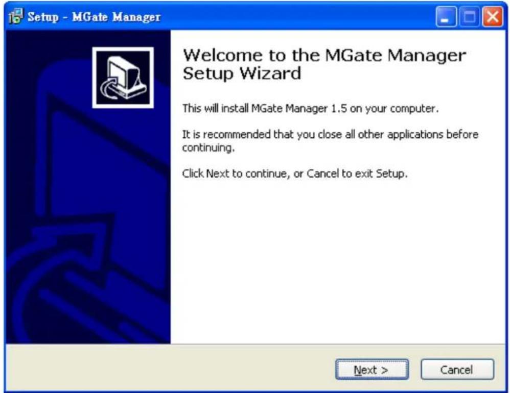
text_image
Setup - MGate Manager Welcome to the MGate Manager Setup Wizard This will install MGate Manager 1.5 on your computer. It is recommended that you close all other applications before continuing. Click Next to continue, or Cancel to exit Setup. Next > Cancel- When the Select Destination Location window appears, click Next to continue. You may change the destination directory by first clicking on Browse.
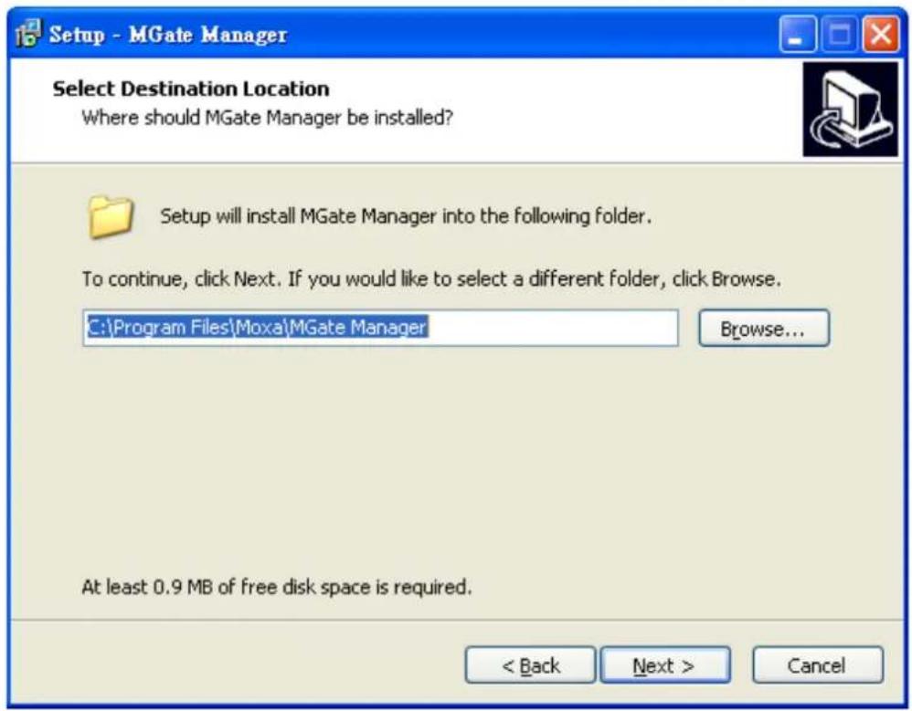
text_image
Setup - MGate Manager Select Destination Location Where should MGate Manager be installed? Setup will install MGate Manager into the following folder. To continue, click Next. If you would like to select a different folder, click Browse. C:\Program Files\Moxa\MGate Manager Browse... At least 0.9 MB of free disk space is required. < Back Next > Cancel- When the Select Additional Tasks window appears, click Next to continue. You may select Create a desktop icon if you would like a shortcut to MGate Manager on your desktop.
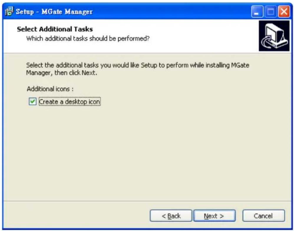
text_image
Setup - MGate Manager Select Additional Tasks Which additional tasks should be performed? Select the additional tasks you would like Setup to perform while installing MGate Manager, then click Next. Additional icons : ✓ Create a desktop icon < Back Next > Cancel- Click Next to start copying the software files.
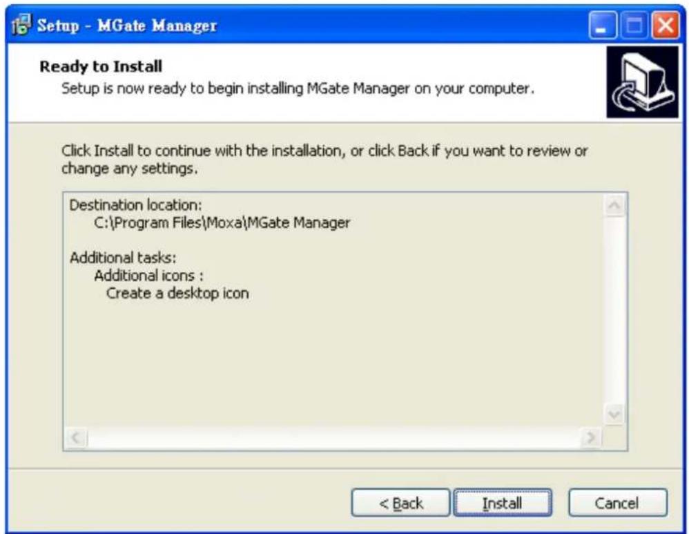
text_image
Setup - MGate Manager Ready to Install Setup is now ready to begin installing MGate Manager on your computer. Click Install to continue with the installation, or click Back if you want to review or change any settings. Destination location: C:\Program Files\Moxa\MGate Manager Additional tasks: Additional icons : Create a desktop icon < Back Install Cancel- A progress bar will appear. The procedure should take only a few seconds to complete.
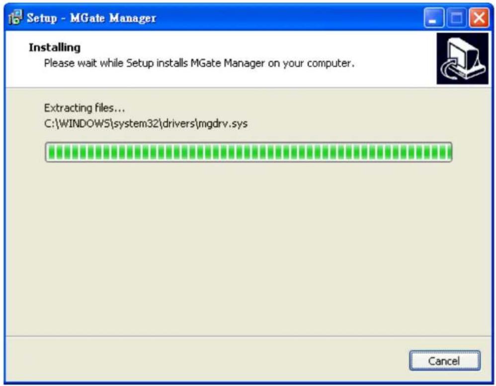
text_image
Setup - MGate Manager Installing Please wait while Setup installs MGate Manager on your computer. Extracting files... C:\WINDOWS\system32\drivers\mgdrv.sys Cancel- A message will indicate that MGate Manager is successfully installed. You may choose to run it immediately by selecting Launch MGate Manager.
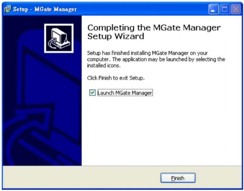
text_image
Setup - MGate Manager Completing the MGate Manager Setup Wizard Setup has finished installing MGate Manager on your computer. The application may be launched by selecting the installed icons. Click Finish to exit Setup. ✓ Launch MGate Manager FinishStarting MGate Manager
MGate Manager is a Windows-based utility that is used to configure the MGate 4101-MB-PBS.
Before running MGate Manager, make sure that the MGate 4101-MB-PBS is connected to your PC. Please refer to Chapter 2 for more details.
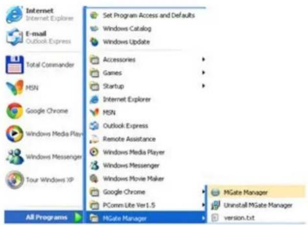
You may open MGate Manager from the Windows Start menu by clicking Start → Programs → MGate Manager → MGate Manager. The MGate Manager window should appear as shown below.
text_image
Internet Internet Explorer E-mail Outlook Express Total Commander MSN Google Chrome Windows Media Playn Windows Messenger Tour Windows XP All Programs Set Program Access and Defaults Windows Catalog Windows Update Accessories Games Startup Internet Explorer MSN Outlook Express Remote Assistance Windows Media Player Windows Messenger Windows Movie Maker Google Chrome PComm Lite Ver1.5 MGate Manager Uninstall MGate Manager version.bitChange Language Setting
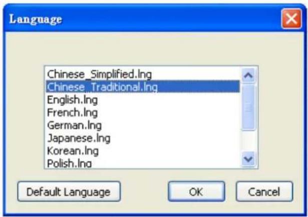
If you wish to run MGate Manager in a different language, you may click Language to change the language setting. A dialog box showing the available languages should appear as shown below.
text_image
Language Chinese_Simplified.Ing Chinese_Traditional.Ing English.Ing French.Ing German.Ing Japanese.Ing Korean.Ing Polish.Ing Default Language OK CancelWhen you click OK, MGate Manager will immediately reflect your chosen language.
text_image
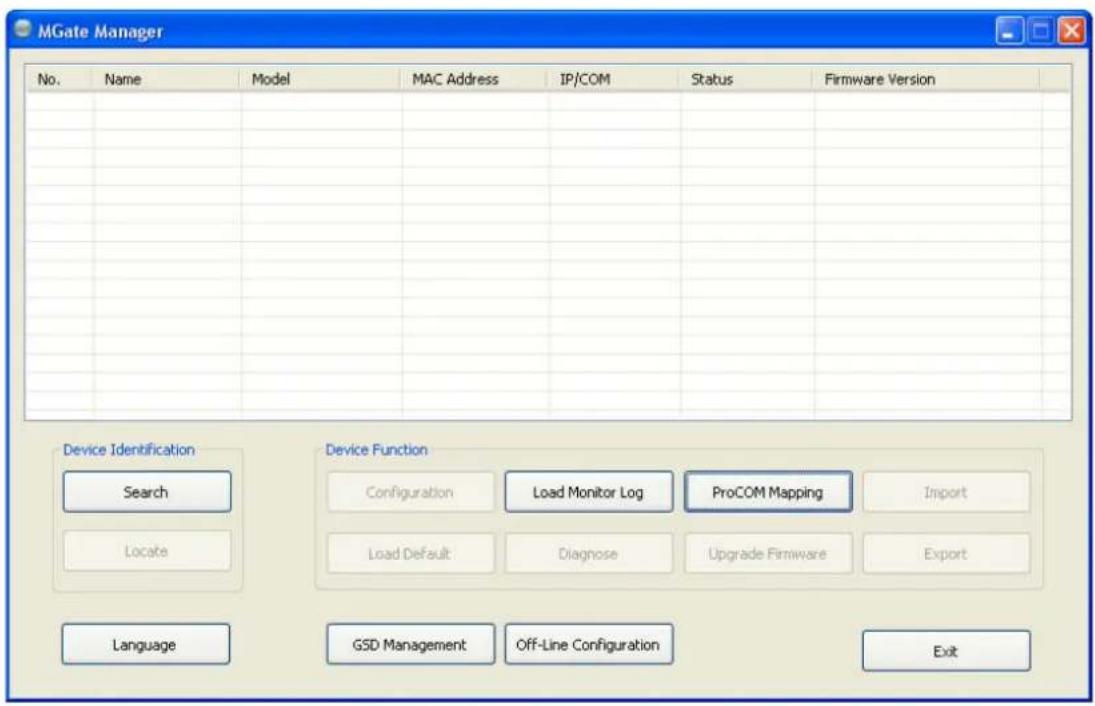
MGate Manager No. Name Model MAC Address IP/COM Status Firmware Version Device Identification Device Function Search Load Monitor Log ProCOM Mapping Import Locate Load Default Diagnose Upgrade Firmware Export Language GSD Management Off-Line Configuration ExitAfter changing to a different language, you will find that all strings on MGate Manager are replaced in your chosen language. For example, the above picture is shown in English. However, no matter what language you choose, it won't change the label on the language button.

ATTENTION
Set your MGate Manager to "Default Language" before contacting Moxa Technical Support.
With support for multiple languages, MGate Manager is more user-friendly and accessible. However, if you need assistance from Moxa Technical Support, please change the language to "Default Language". This will prevent any misunderstandings or confusion about MGate Manager menu items and commands as our engineers assist you.
The default language is English and will only be active for the current MGate Manager session. When you open MGate Manager again, the language will revert to your original setting.
Connecting to the Unit
Prior to configuration, MGate Manager must be connected to its unit. There are three methods to establish connection. Broadcast Search locates the MGate series on the LAN. Search by IP attempts to connect to a specific unit by IP address, which is useful if the unit is located outside the LAN or can only be accessed by going through a router. Connect through COM port tries to connect to a separate unit via a RS-232 serial COM port.
Broadcast Search
Broadcast Search is used for MGate Ethernet Gateways, such as the MGate MB3000 and MGate EIP3000 series, which are discovered via Ethernet by using broadcast IP. In addition, whenever you add an MGate 4101-MB-PBS via serial console, MGate Manager will automatically record the COM port(s) for the broadcast to search as well. Note that restarting MGate Manager will erase the COM port(s) record.
Specify by IP Address
Specify by IP Address is used for MGate Ethernet Gateways, such as the MGate MB3000 and MGate EIP3000 series, which are discovered via Ethernet by using a specific IP address. Click Specify by IP Address if you know the IP address of the unit and wish to connect to it directly.

ATTENTION
If Search by IP Address fails to locate the MGate MB3000 or MGate EIP3000 series, the IP address that you entered might be incorrect. Try doing the search again and re-entering the IP address carefully.
Another possibility is that the MGate MB3000 or MGate EIP3000 series is located on the same LAN as your PC, but on a different subnet. In this case, you can modify your PC's IP address and or netmask so that it is on the same subnet as the MGate MB3000 or MGate EIP3000 series. After your PC and the MGate MB3000 or MGate EIP3000 series are on the same subnet, MGate Manager should be able to find the unit.
Connect through COM Port
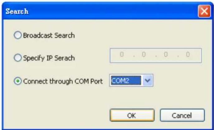
Connect through COM Port is used for MGate PROFIBUS Gateways, such as the MGate 4101-MB-PBS series, which are discovered via RS-232 serial COM Port. Click Connect through COM Port if you know the COM port number of the unit.
Search
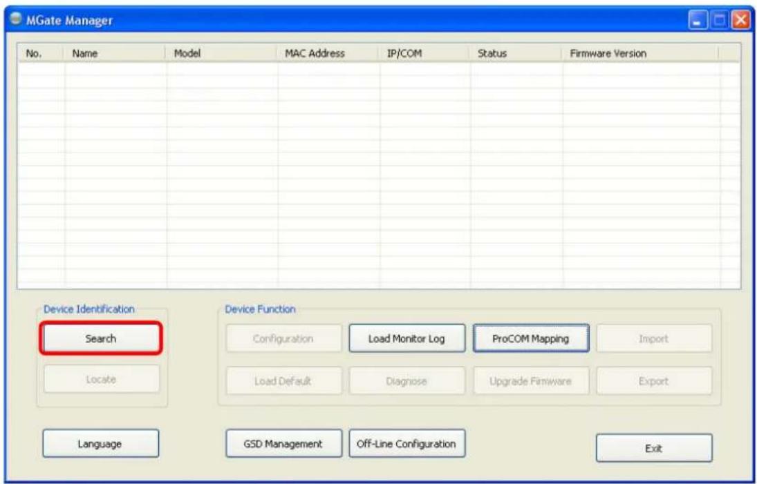
Click Search to begin searching the serial console for the MGate 4101-MB-PBS units.
text_image
MGate Manager No. Name Model MAC Address IP/COM Status Firmware Version Device Identification Search Device Function Configuration Load Monitor Log ProCOM Mapping Import Locate Load Default Diagnose Upgrade Firmware Export Language GSD Management Off-Line Configuration ExitA dialog box will appear. Click Connect through COM Port and choose which COM port is used to connect to MGate 4101-MB-PBS.
text_image
Search ○ Broadcast Search ○ Specify IP Serach ● Connect through COM Port COM2 OK Cancel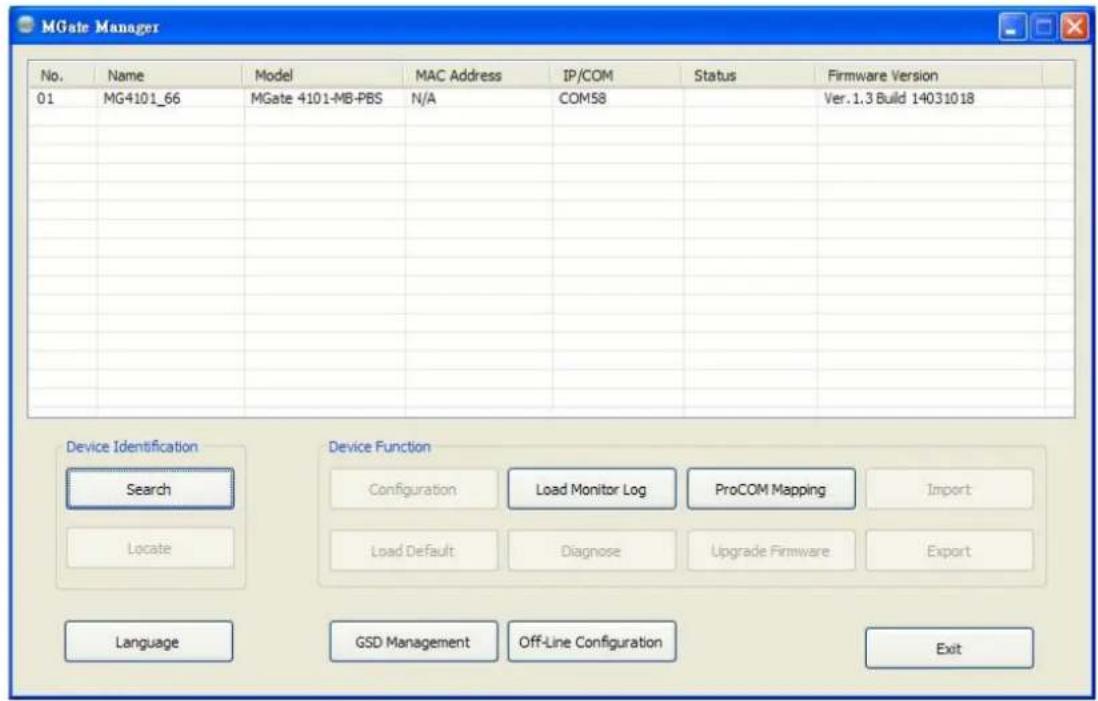
text_image
MGate Manager No. Name Model MAC Address IP/COM Status Firmware Version 01 MG4101_66 MGate 4101-MB-PBS N/A COM58 Ver.1.3 Build 14031018 Device Identification Device Function Search Load Monitor Log ProCOM Mapping Import Locate Load Default Diagnose Upgrade Firmware Export Language GSD Management Off-Line Configuration ExitModifying the Configuration
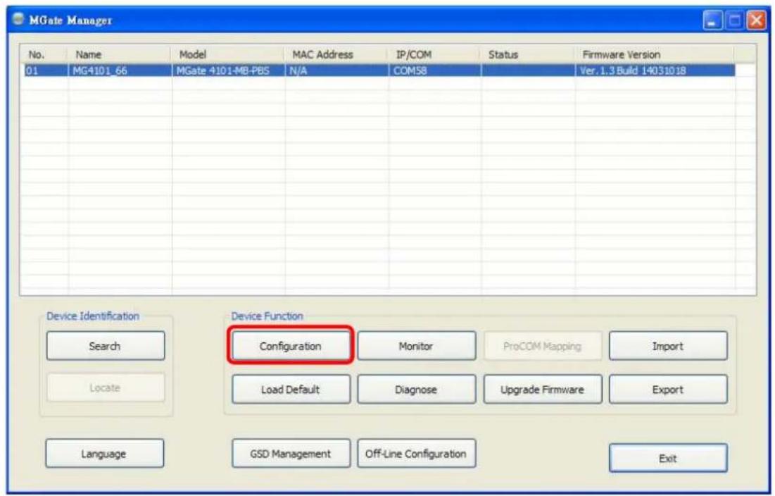
Once your unit is displayed in MGate Manager, select it by clicking on it. The Configuration button will become available. Click Configuration to open the configuration window.
text_image
MGate Manager No. Name Model MAC Address IP/COM Status Firmware Version 01 MG4101_66 MGate 4101-MB-PBS N/A COM58 Ver.1.3 Build 14031018 Device Identification Device Function Search Monitoring ProCOM Mapping Import Locate Load Default Diagnose Upgrade Firmware Export Language GSD Management Off-Line Configuration ExitConfigure Device
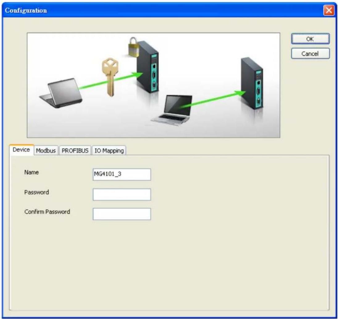
In first page, you can change device name and select a password to protect the unit from unauthorized access.
text_image
Configuration OK Cancel Device Modbus PROFIBUS IO Mapping Name MG4101_3 Password Confirm Password| Parameter Value Notes | ||
| Name | (an alphanumeric string) | You can enter a name to help you identify the unit, such as the location, function, etc. |
| Password | (an alphanumeric string) | You can set a password to prevent unauthorized users from configuring the unit. The password will be required when anyone attempts to configure the unit over the network. Modbus operation is not affected by the password. |
| Confirm password | (an alphanumeric string) | Re-type the password again for confirmation. |

ATTENTION
To erase an existing password, leave both the New Password and Confirm Password text input boxes blank. The password will be erased when you click OK in the bottom right corner.
Configure Modbus Settings
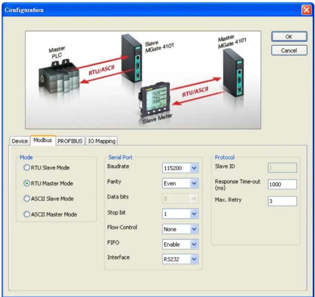
The Serial tab is where Modbus serial port's communication parameters are configured. You can configure Baud Rate, Parity, Stop Bit, Flow Control, FIFO, and Interface Mode.
text_image
Configuration Master PLC RTU/ASCII Slave MGate 4101 Master MGate 4101 Slave Meter RTU/ASCII Device Modbus PROFIBUS IO Mapping Mode RTU Slave Mode RTU Master Mode ASCII Slave Mode ASCII Master Mode Serial Port Baudrate 115200 Parity Even Data bits 8 Stop bit 1 Flow Control None FIFO Enable Interface RS232 Protocol Slave ID 1 Response Time-out (ms) 1000 Max. Retry 3| Mode Description | |
| RTU Master | Modbus RTU slave(s) will be connected to the serial port |
| RTU Slave | A Modbus RTU master will be connected to the serial port |
| ASCII Master | Modbus ASCII slave(s) will be connected to the serial port |
| ASCII Slave | A Modbus ASCII master will be connected to the serial port |
| Serial Port Description | |
| Baud Rate | 50 bps to 921600 bps |
| Parity | None, Odd, Even, Mark, Space |
| Data Bits 8 | |
| Stop Bits 1, 2 | |
| Flow Control | None, DTR/ DSR, RTS/CTS |
| FIFO | Enable, Disable |
| Interface | RS-232, RS-422, RS-485 2-wire, RS-485 4-wire |
| Protocol Description | |
| Slave ID | Slave mode only, Modbus slave identification number of the MGate 4101-MB-PBS |
| Response Time-out (ms) | Master mode only, the time master will wait for a response after sending a request. See detailed description below. |
| Max. Retry | Master mode only, the number of times the master will retry the same request when response time out. |
Response Time-Out
According to the Modbus standard, the time that it takes for a slave device to respond to a request is defined by the device manufacturer (please refer to Appendix A of MGate MB3000 series User Manual for details). Based on this response time, a master can be configured to wait a certain amount of time for a slave's response. If no response is received within the specified time, the master will disregard the request and continue operation. This allows the Modbus system to continue operation even if a slave device is disconnected or faulty.
On the MGate 4101-MB-PBS, the "Response Time-out" field is used to configure how long the gateway will wait for a response from a Modbus ASCII or RTU slave. Please refer to your device manufacturer's documentation to manually set the response time-out.
Set Up PROFIBUS
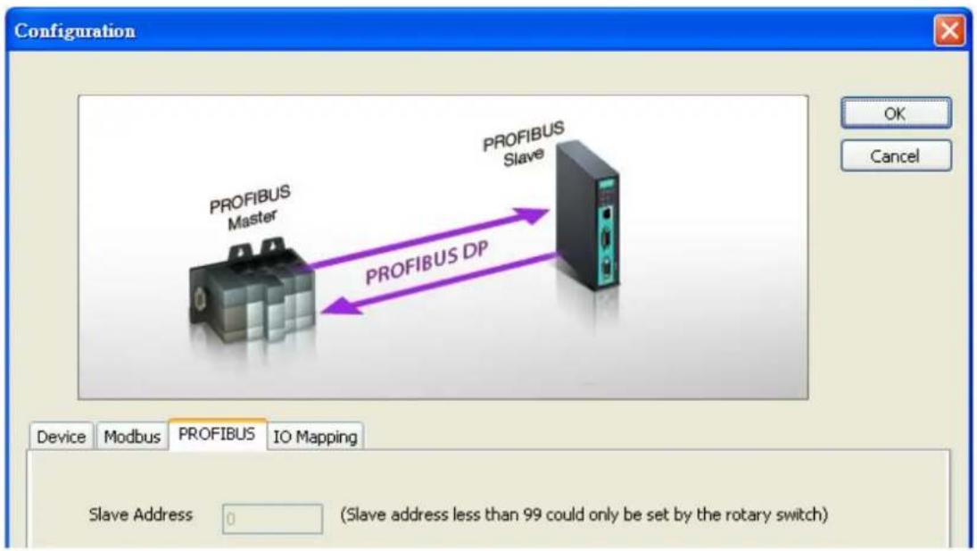
Every PROFIBUS slave device should be assigned a unique address in the same field. If the address you would assign is lower than 99, please use the rotary switches (decimal) on the top of device. If the address you would assign is higher than 99, please set the rotary switches as 99 and Slave Address field will be enabled for setting the designated address.
text_image
Configuration PROFIBUS Master PROFIBUS DP PROFIBUS Slave Device Modbus PROFIBUS IO Mapping Slave Address 0 (Slave address less than 99 could only be set by the rotary switch) OK Cancel| PROFIBUS Description | |
| Slave Address | Before communication, you must assign a slave ID to the PROFIBUS slave, If you would like to assign an address between 0-99, you need to change the rotary switch to the desired address. If you would like to assign an address which is over 99, you must set it in the MGate utility.If you would like to use a slave address which is over 99, set the rotary switch to “99” and then use MGate Manager to configure the desired address. |
Refer to chapter 3 for instructions on how to set the slave address using a rotary switch.
IO Mapping Setup
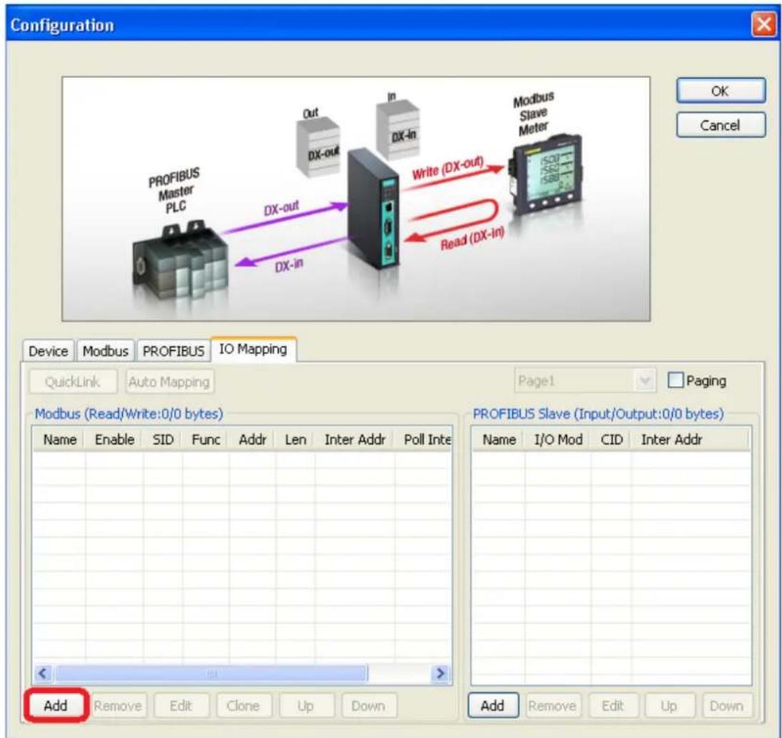
In this page, you should define all commands that Modbus uses and all I/O modules PROFIBUS slave provides.
text_image
Configuration OK Cancel PROFIBUS Master PLC Out DX-out In DX-In Write (DX-out) Read (DX-in) Modbus Slave Meter Device Modbus PROFIBUS IO Mapping QuickLink Auto Mapping Page1 Paging Modbus (Read/Write:0/0 bytes) Name Enable SID Func Addr Len Inter Addr Poll Inte PROFIBUS Slave (Input/Output:0/0 bytes) Name I/O Mod CID Inter Addr Add Remove Edit Clone Up Down Add Remove Edit Up DownIf you choose MGate 4101-MB-PBS as Modbus Master, you should designate all Modbus Read or Write requests in the table on the left.
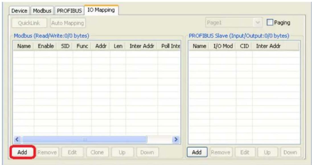
Click Add to create each Modbus request.
text_image
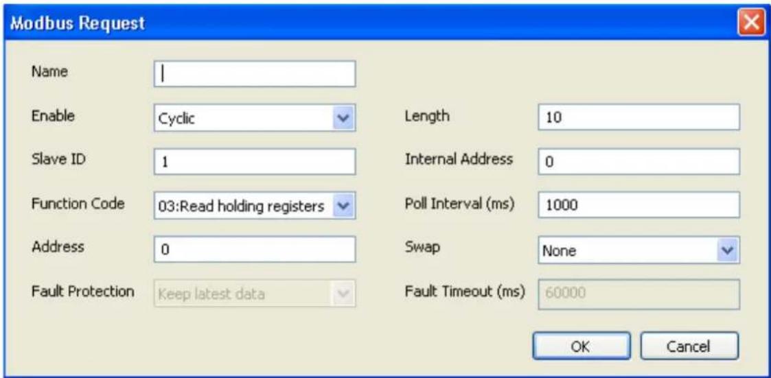
Device Modbus PROFIBUS IO Mapping QuickLink Auto Mapping Page1 Paging Modbus (Read/Write:0/0 bytes) Name Enable SID Func Addr Len Inter Addr Poll Inte Add Remove Edit Clone Up Down PROFIBUS Slave (Input/Output:0/0 bytes) Name I/O Mod CID Inter Addr Add Remove Edit Up DownEach Modbus request includes Name, Enable, Modbus slave ID, Function Code, Address, Length, Internal Address, Poll Interval, Swap, Fault Protection, Fault Timeout. Please refer to datasheets or manuals of Modbus slave devices to fill out these fields.
text_image
Modbus Request Name Enable Slave ID Function Code Address Fault Protection I Cyclic 1 03:Read holding registers 0 Keep latest data Length 10 Internal Address 0 Poll Interval (ms) 1000 Swap None Fault Timeout (ms) 60000 OK Cancel| Parameter Description | |
| Name | Enter a name to help identify the command, such as the location, function etc. |
| Enable | The Enable for the transaction:Disable: The transaction is never sentCyclic: The transaction is sent cyclically at the interval specified in the “Poll Interval” parameter.Data change: The data area is polled for changes at the time interval defined by Poll Interval. A transaction is issued when a change in data is detected. |
| Slave ID | The Modbus slave id that this slave module will accept.0: Broadcasting1-255: Device specific |
| Function Code | When a message is sent from a Client to a Server device the function code field tells the server what kind of action to perform.We support the following function code by far:01: Read coils02: Read discrete inputs03: Read holding registers04: Read input register05: Write single coil06: Write single register15: Write multiple coils16: Write multiple registers |
| Address | Station Address. The range is from 0 to 65535 |
| Length | The length field is a byte count of the following fields, including the Unit Identifier and data fields. The range is from 1 to 1953. |
| Internal Address | This parameter specifies the location of the trigger byte in internal memory. The range is from 0 to 243. |
| Poll Interval (ms) | Polling interval in millisecond, since the module sends all requests in turns, the actual polling interval also depends on the number of requests in the queue and their parameters. The range is from 10 to 1200000. |
| Swap Data Byte Swapping | None: Don't need to swapByte: 0x0A, 0x0B, 0x0C, 0x0D becomes 0x0D, 0x0C, 0x0B, 0x0A.Word: 0x0A, 0x0B, 0x0C, 0x0D becomes 0x0C, 0x0D, 0x0A, 0x0B.ByteWord: 0x0A, 0x0B, 0x0C, 0x0D becomes 0x0D, 0x0C, 0x0B, 0x0A.There are two phases in changing ByteWord1). 0x0A, 0x0B, 0x0C, 0x0D becomes 0x0B, 0x0A, 0x0D, 0x0C.2). 0x0B, 0x0A, 0x0D, 0x0C becomes 0x0D, 0x0C, 0x0B, 0x0A. |
| Fault Protection | For the Modbus RTU master mode, the opposite side refers to the PROFIBUS side. The Modbus write command is sent from the PROFIBUS. Once the PROFIBUS connection fails, the gateway will not be able to receive the PROFIBUS command, but the gateway will continuously send Modbus write commands to the Modbus RTU slave device. To avoid problems when the PROFIBUS side fails, the MGate 4101 can be configured to react in one of three ways: keep latest data, clear data to zero, and user-defined value. |
| Fault Timeout | Defines the communication timeout for the PROFIBUS side. The range is from 0 to 65535 ms. (the default setting is 60000 ms.) |
Fault Protection
The Fault Protection function sends a predefined setting to field devices to prevent incorrect actions when an upstream connection is lost. You can configure the criteria used to determine what to do when the write command is no longer received from the PROFIBUS side. For example, when a PROFIBUS cable comes loose accidentally, the most up-to-date write command from the PROFIBUS side will not be received by the gateway. Hence, the Modbus master will continuously send Modbus write commands to the slave device, which is now out-of-date, creating an inconsistency between the PROFIBUS and Modbus sides. To avoid this problem, the MGate 4101 supports options to determine which actions should be taken when the PROFIBUS side is disconnected from the gateway.
| Options Description | |
| Keep latest data | The gateway will write the same data to the slave device. |
| Clear data to zero | The gateway will write zero values to the slave device. |
| User-defined value | A user-defined value will be written to the slave device. |
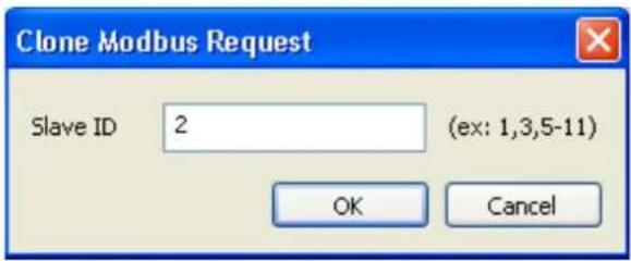
After adding a command, you find out that many similar commands with different slave IDs need to be configured. You can choose (Ctrl + click-left) desired commands and press Clone to duplicate commands.
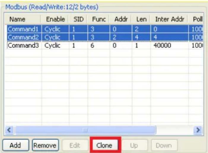
text_image
Modbus (Read/Write:12/2 bytes) Name Enable SID Func Addr Len Inter Addr Poll Command1 Cyclic 1 3 0 2 0 100 Command2 Cyclic 1 3 2 4 4 100 Command3 Cyclic 1 6 0 1 40000 100 Add Remove Edit Clone Up DownThen, a dialog box that is used to set the desired Slave ID will appear. The Slave ID range could be set and then click OK to produce commands.
text_image
Clone Modbus Request Slave ID 2 (ex: 1,3,5-11) OK Cancel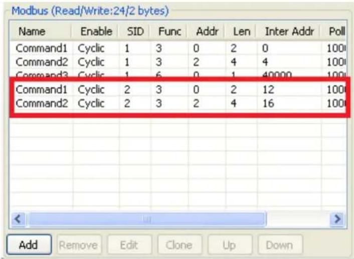
text_image
Modbus (Read/Write:24/2 bytes) Name Enable SID Func Addr Len Inter Addr Poll Command1 Cyclic 1 3 0 2 0 100 Command2 Cyclic 1 3 2 4 4 100 Command3 Cyclic 1 6 0 1 40000 100 Command1 Cyclic 2 3 0 2 12 100 Command2 Cyclic 2 3 2 4 16 100 Add Remove Edit Clone Up DownAfter all Modbus requests finish, all the data collected from Modbus should be mapped to PROFIBUS I/O modules for the PROFIBUS Master to use.
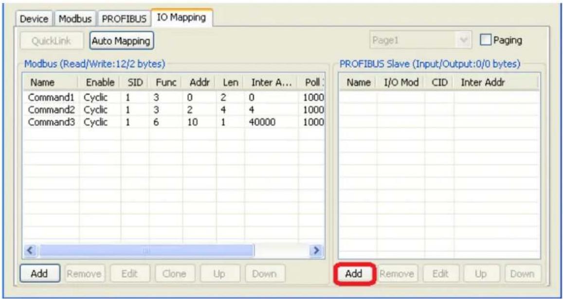
Click Add to create each PROFIBUS I/O module in the table on the right.
text_image
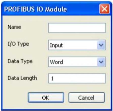
Device Modbus PROFIBUS IO Mapping QuickLink Auto Mapping Page1 Paging Modbus (Read/Write:12/2 bytes) PROFIBUS Slave (Input/Output:0/0 bytes) Name Enable SID Func Addr Len Inter A... Poll : Command1 Cyclic 1 3 0 2 0 1000 Command2 Cyclic 1 3 2 4 4 1000 Command3 Cyclic 1 6 10 1 40000 1000 Add Remove Edit Clone Up Down Remove Edit Up Down Add Remove Edit Up DownThen, a dialog which is used to set up the IO module will appear, please adjust the parameters which correspond with the Modbus requests you set before. Click OK to record this IO module.
text_image
PROFIBUS IO Module Name I/O Type Input Data Type Word Data Length 1 OK Cancel| Parameter Description | |
| Name | Enter a name to help identify the module, such as the location, function etc. |
| I/O Type | Input: Used to map into input memoryOutput: Used to map into output memory |
| Data Type | The data type for this IO module |
| Data Length | The data length for this IO module. The range is from 1 to 64. |
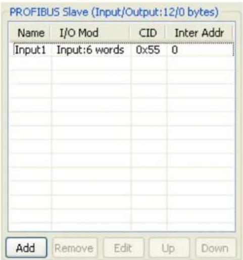
Finally, you can see the IO module you configure before is put into PROFIBUS Slave list.
text_image
PROFIBUS Slave (Input/Output:12/0 bytes) Name I/O Mod CID Inter Addr Input1 XiInput:6 words 0x55 0 Add Remove Edit Up DownFollow the steps above; you can map all of the Modbus requests you need into IO module.
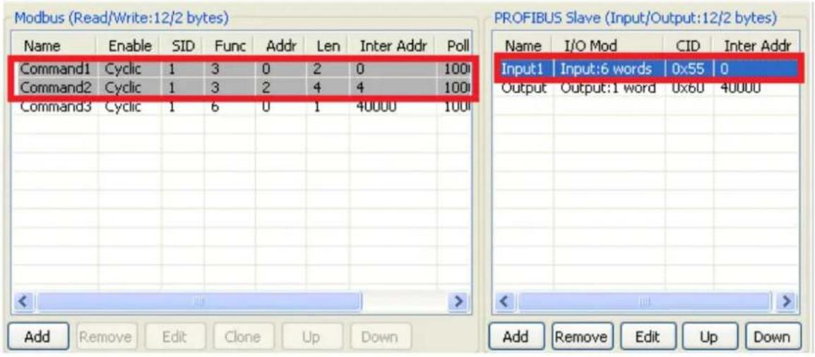
If you would like to check if the I/O map is totally correct, you could click PROFIBUS I/O module that will show what Modbus commands are included in the table on the right. After finishing the configuration, MGate 4101-MB-PBS can communicate between the PROFIBUS and Modbus protocols.
text_image
Modbus (Read/Write:12/2 bytes) Name Enable SID Func Addr Len Inter Addr Poll Command1 Cyclic 1 3 0 2 0 100 Command2 Cyclic 1 3 2 4 4 100 Command3 Cyclic 1 6 0 1 40000 100 PROFIBUS Slave (Input/Output:12/2 bytes) Name I/O Mod CID Inter Addr Input1 Input:6 words 0x55 0 Output Output:1 word 0x60 40000 Add Remove Edit Clone Up Down Add Remove Edit Up DownNOTE Each "Name" of the commands must be mapped, that is, the commands in Modbus will correspond with the I/O module in PROFIBUS.
Auto Mapping
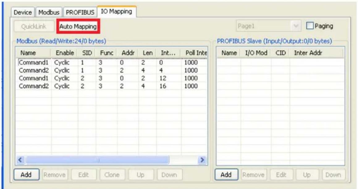
Auto Mapping is a useful function that can help you map Modbus commands to PROFIBUS I/O modules easily. This function is for Modbus master mode only. Typically, users need to spend lots of time in setting I/O modules. By using the Auto Mapping function, it will map Modbus commands to PROFIBUS I/O modules automatically. You can map it in one of three ways: All-in-one, One-to-one, or by Slave ID.
text_image
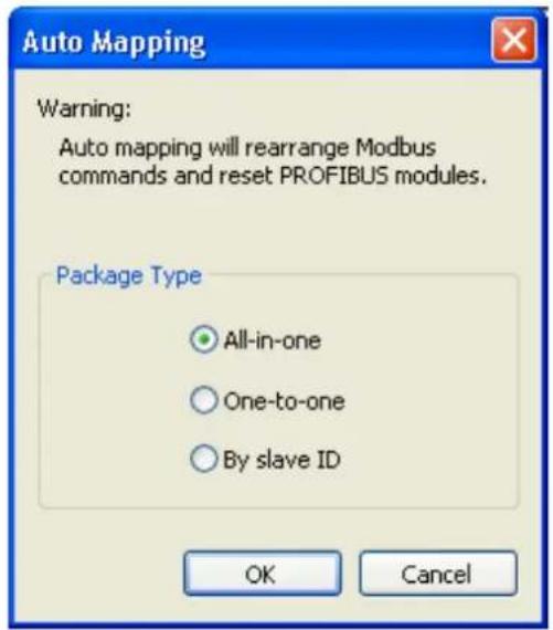
Device Modbus PROFIBUS IO Mapping QuickLink Auto Mapping Page1 Paging Modbus (Read/Write:24/0 bytes) PROFIBUS Slave (Input/Output:0/0 bytes) Name Enable SID Func Addr Len Int... Poll Inte Command1 Cyclic 1 3 0 2 0 1000 Command2 Cyclic 1 3 2 4 4 1000 Command1 Cyclic 2 3 0 2 12 1000 Command2 Cyclic 2 3 2 4 16 1000 Add Remove Edit Clone Up Down Add Remove Edit Up DownClick the Auto Mapping function. Then, a dialog box that is used to select the package types will appear. Please select one of them to map Modbus commands. Click OK to produce PROFIBUS I/O modules.
text_image
Auto Mapping Warning: Auto mapping will rearrange Modbus commands and reset PROFIBUS modules. Package Type All-in-one One-to-one By slave ID OK Cancel| Package Type Description | |
| All-in-one | Combine all the Modbus read/write commands to PROFIBUS one input/output module respectively. |
| One-to-one | Combine each Modbus read/write command to PROFIBUS each input/output module respectively. |
| By slave ID | Combine Modbus read/write commands by slave ID to PROFIBUS input/output modules respectively. |
QuickLink
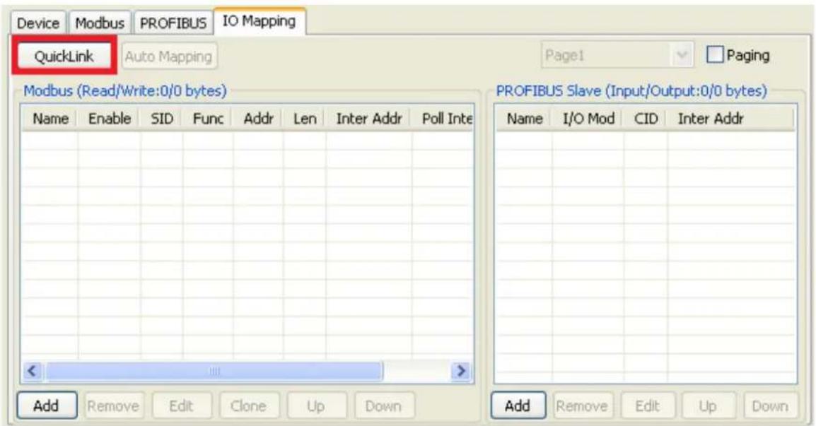
The QuickLink is an innovative function to let you configure more quickly and easily, Typically, most PROFIBUS users must spend a lot of time to set up Modbus commands in a PROFIBUS application. By using the QuickLink function, the MGate 4101-MB-PBS will learn Modbus requests automatically to save time in deployment. However, the function is only enabled in Modbus master mode. (Please refer to the Typical Application in the Appendix for more details). Start QuickLink by clicking the QuickLink button.
text_image
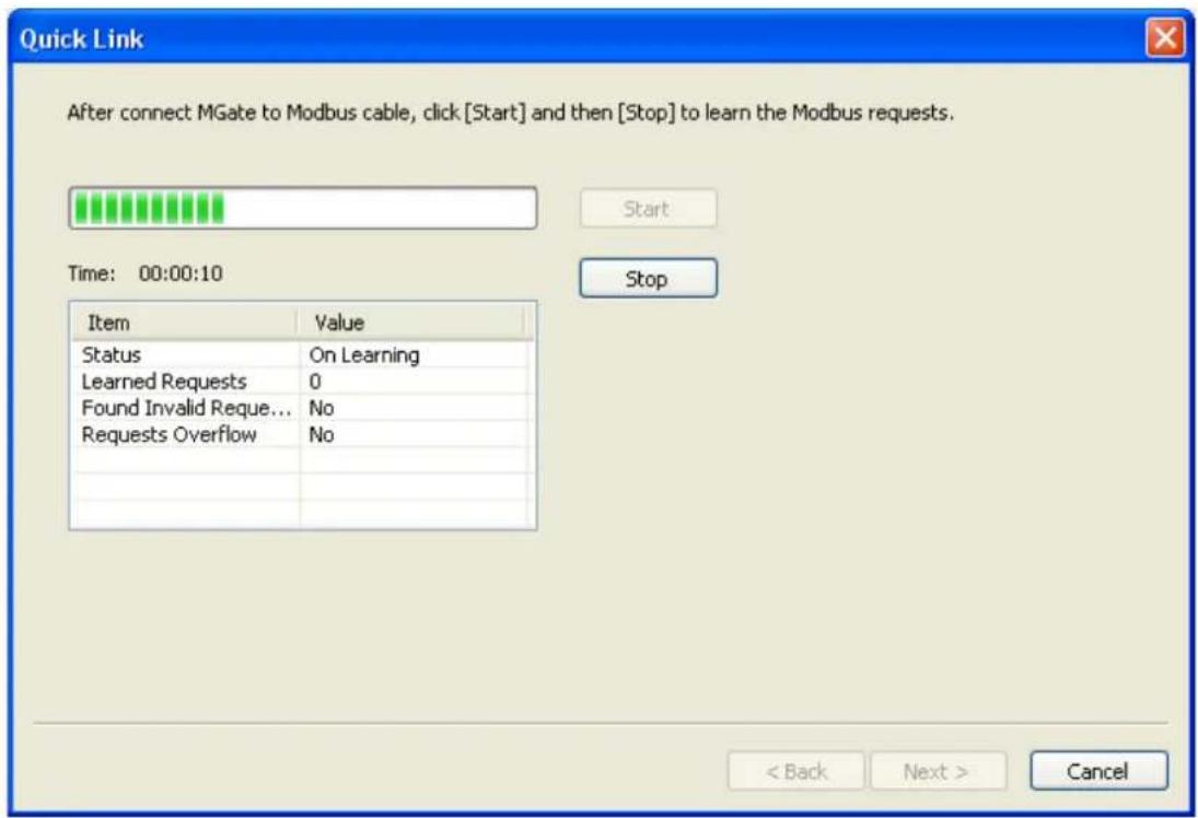
Device Modbus PROFIBUS IO Mapping QuickLink Auto Mapping Page1 Paging Modbus (Read/Write:0/0 bytes) Name Enable SID Func Addr Len Inter Addr Poll Inte PROFIBUS Slave (Input/Output:0/0 bytes) Name I/O Mod CID Inter Addr Add Remove Edit Clone Up Down Add Remove Edit Up DownIt takes some time to learn the Modbus requests. Begin by clicking the Start button, which will change the status to On Learning. The number of Learned Requests will increase as the MGate 4101-MB-PBS learns each request. When you are sure all the requests have been learned by the MGate 4101-MB-PBS, click the Stop button, then click the Next button to continue QuickLink.
NOTE QuickLink function will work correctly only when all the serial parameter settings are set correctly.
text_image
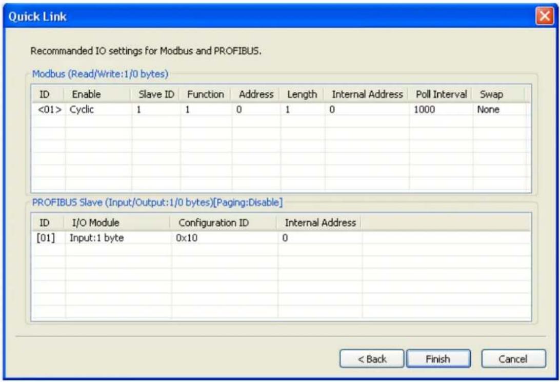
Quick Link After connect MGate to Modbus cable, click [Start] and then [Stop] to learn the Modbus requests. Time: 00:00:10 Item Value Status On Learning Learned Requests 0 Found Invalid Request... No Requests Overflow No < Back Next > CancelThe interface of the next dialogue box is divided into two sections. The upper section is labeled Modbus and will display the details of the Modbus requests which have been learned by the MGate 4101-MB-PBS. The lower section is labeled PROFIBUS Slave and will display the I/O module. Moreover, based on these learned requests, the I/O module blocks are allocated intelligently by MGate Manager. To complete the process, click the Finish button to make the settings work.
text_image
Quick Link Recommended IO settings for Modbus and PROFIBUS. Modbus (Read/Write:1/0 bytes) ID Enable Slave ID Function Address Length Internal Address Poll Interval Swap <01> Cyclic 1 1 0 1 0 1000 None PROFIBUS Slave (Input/Output:1/0 bytes)[Paging:Disable] ID I/O Module Configuration ID Internal Address [01] Input:1 byte 0x10 0 < Back Finish CancelPaging
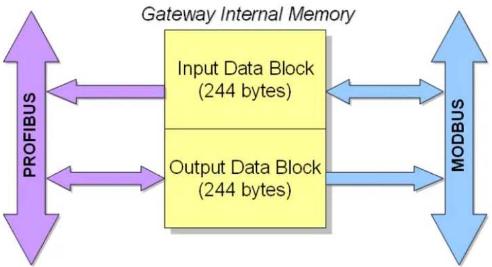
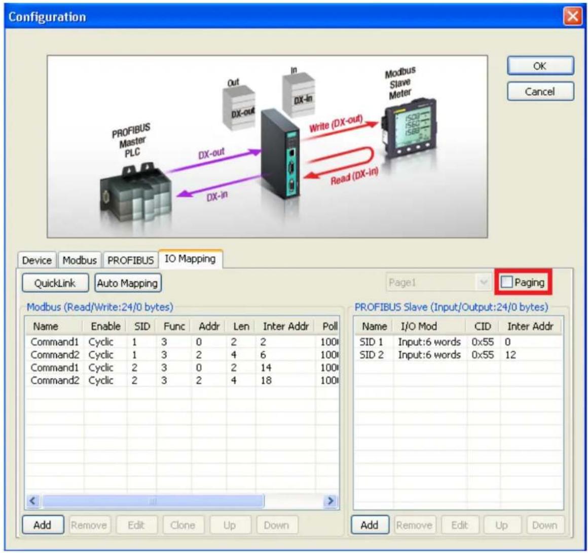
Gateway internal memory is divided into two blocks. The input memory address starts from 0x00000, and the out memory starts from 0x40000. The following picture demonstrates the memory structure. Each page contains 244 bytes.
flowchart
graph LR
    A["PROFIBUS"] --> B["Input Data Block (244 bytes)"]
    B --> C["MODBUS"]
    C --> D["Output Data Block (244 bytes)"]
    D --> B
    style A fill:#purple,stroke:#333
    style B fill:#yellow,stroke:#333
    style C fill:#blue,stroke:#333
    style D fill:#lightblue,stroke:#333
Input refers to the dataflow from the Modbus device to the PROFIBUS master. More specifically, it means the gateway will read the Modbus device's data and store in its input memory area. And the PROFIBUS master will
read these Modbus data stored at the gateway's input memory. Users can choose internal memory address between 0 to 224.
Output refers to the dataflow from the PROFIBUS master to the Modbus devices. The PROFIBUS data that are being written to the Modbus device will be stored at the gateway's output memory area, and then the Modbus device will write those data stored at the gateway's output memory area. Users can choose internal memory address between 40000 to 40242.
text_image
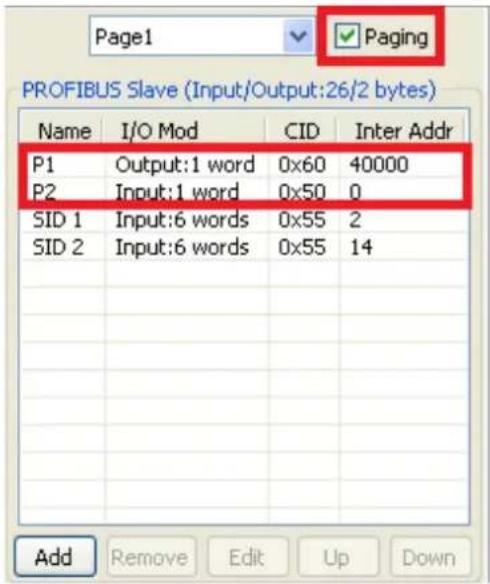
Configuration PROFIBUS Master PLC Out DX-out In DX-In Write (DX-out) Read (DX-in) Modbus Slave Meter Device Modbus PROFIBUS IO Mapping QuickLink Auto Mapping Page1 □ Paging Modbus (Read/Write:24/0 bytes) PROFIBUS Slave (Input/Output:24/0 bytes) Name Enable SID Func Addr Len Inter Addr Poll Command1 Cyclic 1 3 0 2 2 100 Command2 Cyclic 1 3 2 4 6 100 Command1 Cyclic 2 3 0 2 14 100 Command2 Cyclic 2 3 2 4 18 100 Add Remove Edit Clone Up Down Add Remove Edit Up Down SID 1 Input:6 words 0x55 0 SID 2 Input:6 words 0x55 12If you want to exchange data over 244 bytes, you can select the Paging checkbox to enable the page function, so the utility will insert two I/O word modules into the starting location of the input/output memory bank for separate page functionality. Basically, because one I/O module supports 244 bytes only, the paging function can be used to break through this limit. The maximum of input/output memory size is up to 7744 bytes respectively.
The output I/O module, which is called P1, is used to change the page number to the specified one. The first byte of module P1 attempts to switch input page number, and the second byte attempts to change output page number. In addition, the input I/O module, which is called P2, is used to read the current page number. The first byte of module P2 indicates input page number and the second one designates output page number. You can't modify these two I/O modules.
text_image
Page1 ✓ Paging PROFIBUS Slave (Input/Output:26/2 bytes) Name I/O Mod CID Inter Addr P1 Output:1 word 0x60 40000 P2.Input:1 word 0x50 0 SID 1.Input:6 words 0x55 2 SID 2.Input:6 words 0x55 14 Add Remove Edit Up DownLoad Default
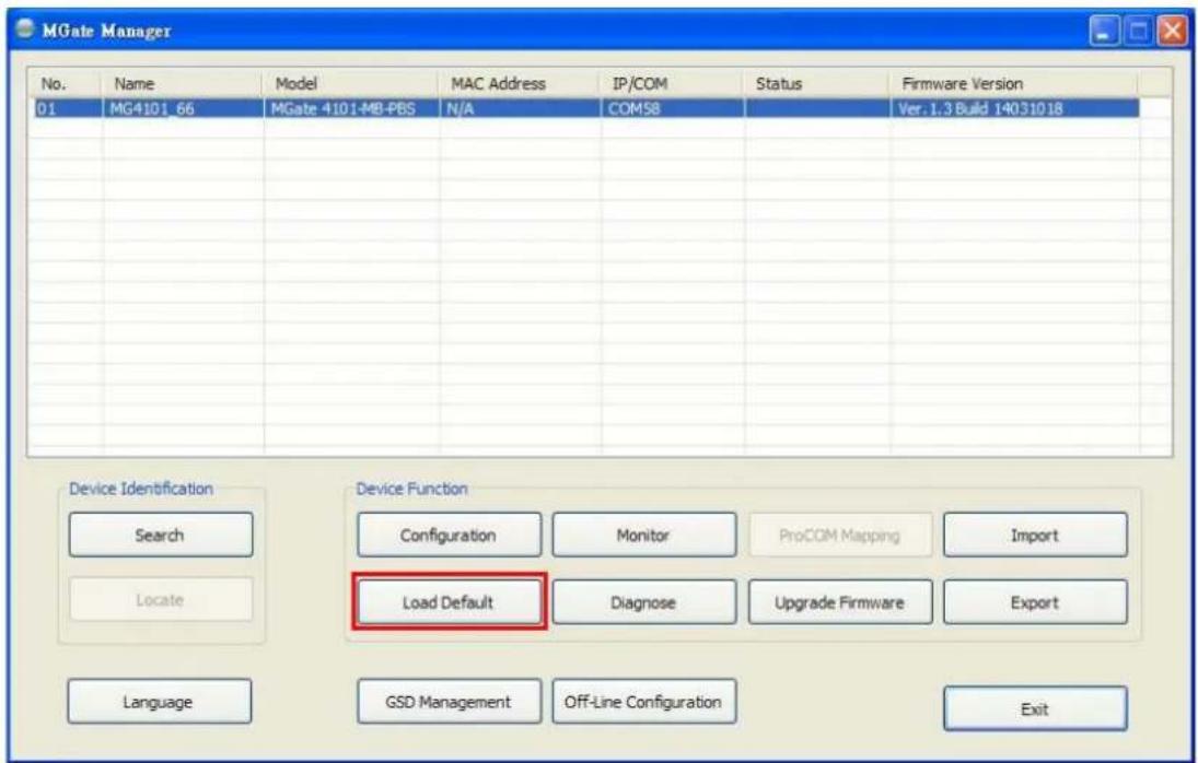
If for some reason you would like to clear all the settings of the unit, the Load Default button will reset the unit to its initial factory default values.
text_image
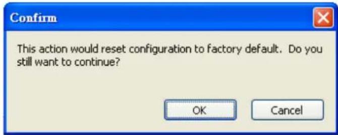
MGate Manager No. Name Model MAC Address IP/COM Status Firmware Version 01 MG4101_66 MGate 4101-MB-PBS N/A COM58 Ver. I.3 Build 14031018 Device Identification Device Function Search Configuration Monitor ProCOM Mapping Import Locate Load Default Diagnose Upgrade Firmware Export Language GSD Management Off-Line Configuration ExitClick Load Default and review the confirmation message. If you are sure you would like to reset the configuration to the factory default, click the OK button. If not, click Cancel.
text_image
Confirm This action would reset configuration to factory default. Do you still want to continue? OK CancelAfter MGate Manager resets completely, it will automatically execute a Broadcast Search for all MGate units on the LAN and the recording COM port. Your MGate should reappear in the list of units.

ATTENTION
Load Default will completely reset the configuration of the unit, and all of the parameters you have saved will be discarded. Do not use this function unless you are sure you want to completely reset your unit.
Monitoring Modbus Activity
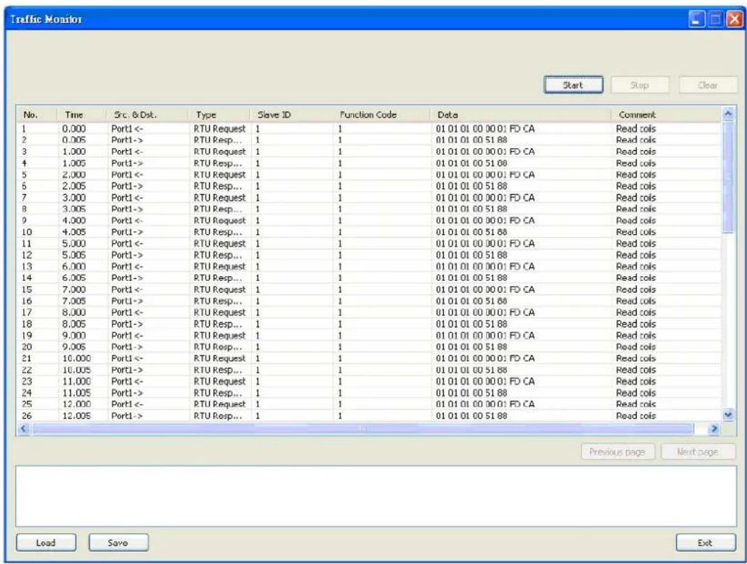
For troubleshooting or management purposes, you can monitor the data passing through any MGate 4101-MB-PBS on the Modbus side. Data events will be logged as they pass through the gateway. Rather than simply echoing the data, MGate Manager presents the data in an intelligent, easily understood format, with clearly designated fields including source, type, destination, contents, and more. Events can be filtered in different ways, and the complete log can be saved to a file for later analysis.
text_image
Traffic Monitor Start Stop Clear No. Time Src. &Dst. Type Slave ID Function Code Data Comment 1 0.000 Port1<- RTU Request 1 1 01 01 01 00 00 01 FD CA Read cols 2 0.005 Port1-> RTU Resp... 1 1 01 01 01 00 51 88 Read cols 3 1.000 Port1<- RTU Request 1 1 01 01 01 00 00 01 FD CA Read cols 4 1.005 Port1-> RTU Resp... 1 1 01 01 01 00 51 00 Read cols 5 2.000 Port1<- RTU Request 1 1 01 01 01 00 00 01 FD CA Read cols 6 2.005 Port1-> RTU Resp... 1 1 01 01 01 00 51 88 Read cols 7 3.000 Port1<- RTU Request 1 1 01 01 01 00 00 01 FD CA Read cols 8 3.005 Port1-> RTU Resp... 1 1 01 01 01 00 51 88 Read cols 9 4.000 Port1<- RTU Request 1 1 01 01 01 00 00 01 FD CA Read cols 10 4.005 Port1-> RTU Resp... 1 1 01 01 01 00 51 88 Read cols 11 5.000 Port1<- RTU Request 1 1 01 01 01 00 00 01 FD CA Read cols 12 5.005 Port1-> RTU Resp... 1 1 01 01 01 00 51 88 Read cols 13 6.000 Port1<- RTU Request 1 1 01 01 01 00 00 01 FD CA Read cols 14 6.005 Port1-> RTU Resp... 1 1 01 01 01 00 51 88 Read cols 15 7.000 Port1<- RTU Request 1 1 01 01 01 00 00 01 FD CA Read cols 16 7.005 Port1-> RTU Resp... 1 1 01 01 01 00 51 88 Read cols 17 8.000 Port1<- RTU Request 1 1 01 01 01 00 00 01 FD CA Read cols 18 8.005 Port1-> RTU Resp... 1 1 01 01 01 00 51 88 Read cols 19 9.000 Port1<- RTU Request 1 1Open Traffic Monitor Window
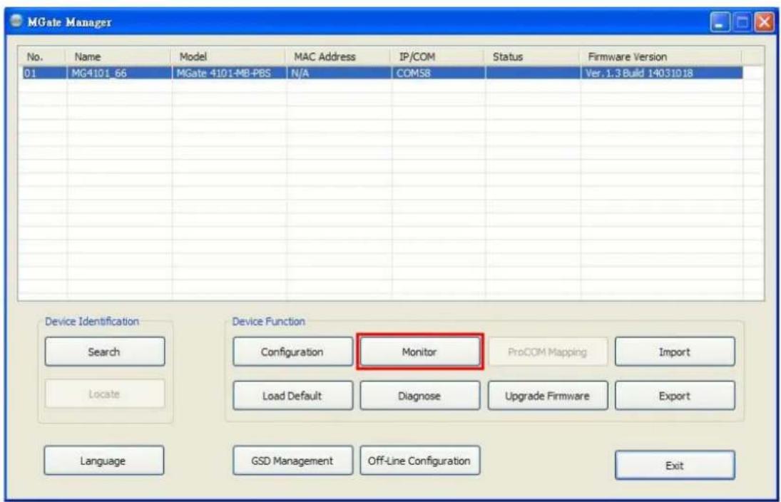
Select the unit that you wish to monitor and click Monitor to open the Traffic Monitor window.
text_image
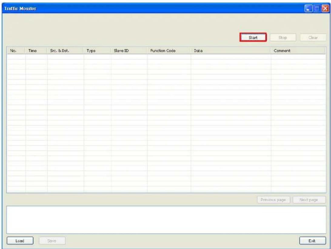
MGate Manager No. Name Model MAC Address IP/COM Status Firmware Version 01 MG4101_66 MGate 4101-MB-PBS N/A COMSB Ver. 1.3 Build 14031018 Device Identification Device Function Search Configuration Monitor ProCOM Mapping Import Locate Load Default Diagnose Upgrade Firmware Export Language GSD Management Off-Line Configuration ExitIn the Traffic Monitor window, click Start to begin live monitoring of the data passing through the selected MGate 4101-MB-PBS unit.
text_image
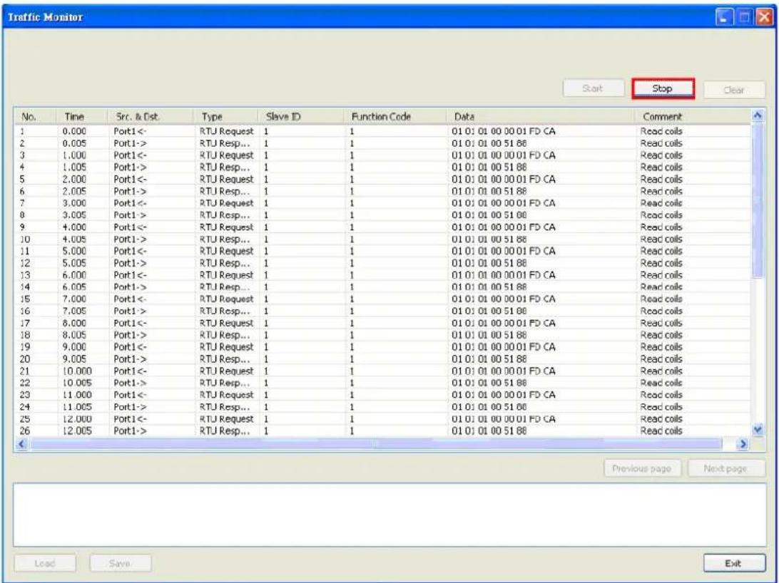
Traffic Monitor Start Stop Clear No. Time Src. & Dist. Type Slave ID Function Code Data Comment Previous page Next page Load Save ExitTo stop capturing the log, press the Stop button.
text_image
Traffic Monitor Start Stop Clear No. Time Src. & Dst. Type Slave ID Function Code Data Comment 1 0.000 Port1<- RTU Request 1 1 01 01 01 00 00 01 FD CA Read coils 2 0.005 Port1-> RTU Resp... 1 1 01 01 01 00 51 86 Read coils 3 1.000 Port1<- RTU Request 1 1 01 01 01 00 00 01 FD CA Read coils 4 1.005 Port1-> RTU Resp... 1 1 01 01 01 00 51 88 Read coils 5 2.000 Port1<- RTU Request 1 1 01 01 01 00 00 01 FD CA Read coils 6 2.005 Port1-> RTU Resp... 1 1 01 01 01 00 51 88 Read coils 7 3.000 Port1<- RTU Request 1 1 01 01 01 00 00 01 FD CA Read coils 8 3.005 Port1-> RTU Resp... 1 1 01 01 01 00 51 88 Read coils 9 4.000 Port1<- RTU Request 1 1 01 01 01 00 00 01 FD CA Read coils 10 4.005 Port1-> RTU Resp... 1 1 01 01 01 00 51 88 Read coils 11 5.000 Port1<- RTU Request 1 1 01 01 01 00 00 01 FD CA Read coils 12 5.005 Port1-> RTU Resp... 1 1 01 01 01 00 51 88 Read coils 13 6.000 Port1<- RTU Request 1 1 01 01 01 00 00 01 FD CA Read coils 14 6.005 Port1-> RTU Resp... 1 1 01 01 01 00 51 88 Read coils 15 7.000 Port1<- RTU Request 1 1 01 01 01 00 00 01 FD CA Read coils 16 7.005 Port1-> RTU Resp... 1 1 01 01 01 00 51 88 Read coils 17 8.000 Port1<- RTU Request 1 1 01 01 01 00 00 01 FD CA Read coils 18 8.005 Port1-> RTU Resp... 1 1 01 01 01 00 51 88 Read coils 19 9.000 Port1<- RTU Request 1 1Save Log to File
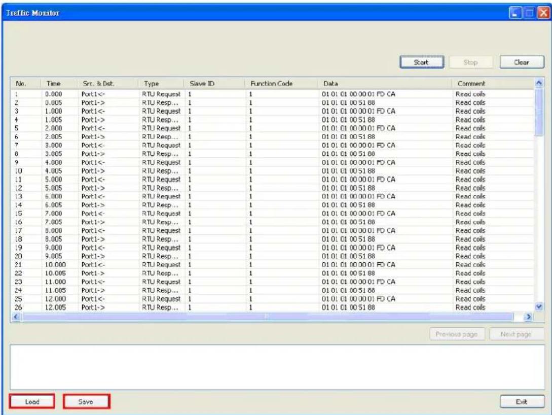
To save the data log to a file, click Save. You may retrieve a saved log by clicking Load.
text_image
Traffic Monitor Start Stop Clear No. Time Src. & Dst. Type Save ID Function Code Data Comment 1 0.000 Port1<- RTU Request 1 1 01 01 01 00 00 01 FD CA Read coils 2 0.005 Port1-> RTU Resp... 1 1 01 01 01 00 51 88 Read coils 3 1.000 Port1<- RTU Request 1 1 01 01 01 00 00 01 FD CA Read coils 4 1.005 Port1-> RTU Resp... 1 1 01 01 01 00 51 88 Read coils 5 2.000 Port1<- RTU Request 1 1 01 01 01 00 00 01 FD CA Read coils 6 2.005 Port1-> RTU Resp... 1 1 01 01 01 00 51 88 Read coils 7 3.000 Port1<- RTU Request 1 1 01 01 01 00 00 01 FD CA Read coils 8 3.005 Port1-> RTU Resp... 1 1 01 01 01 00 51 88 Read coils 9 4.000 Port1<- RTU Request 1 1 01 01 01 00 00 01 FD CA Read coils 10 4.005 Port1-> RTU Resp... 1 1 01 01 01 00 51 88 Read coils 11 5.000 Port1<- RTU Request 1 1 01 01 01 00 00 01 FD CA Read coils 12 5.005 Port1-> RTU Resp... 1 1 01 01 01 00 51 88 Read coils 13 6.000 Port1<- RTU Request 1 1 01 01 01 00 00 01 FD CA Read coils 14 6.005 Port1-> RTU Resp... 1 1 01 01 01 00 51 88 Read coils 15 7.000 Port1<- RTU Request 1 1 01 01 01 00 00 01 FD CA Read coils 16 7.005 Port1-> RTU Resp... 1 1 01 01 01 00 51 88 Read coils 17 8.000 Port1<- RTU Request 1 1 01 01 01 00 00 01 FD CA Read coils 18 8.005 Port1-> RTU Resp... 1Diagnose
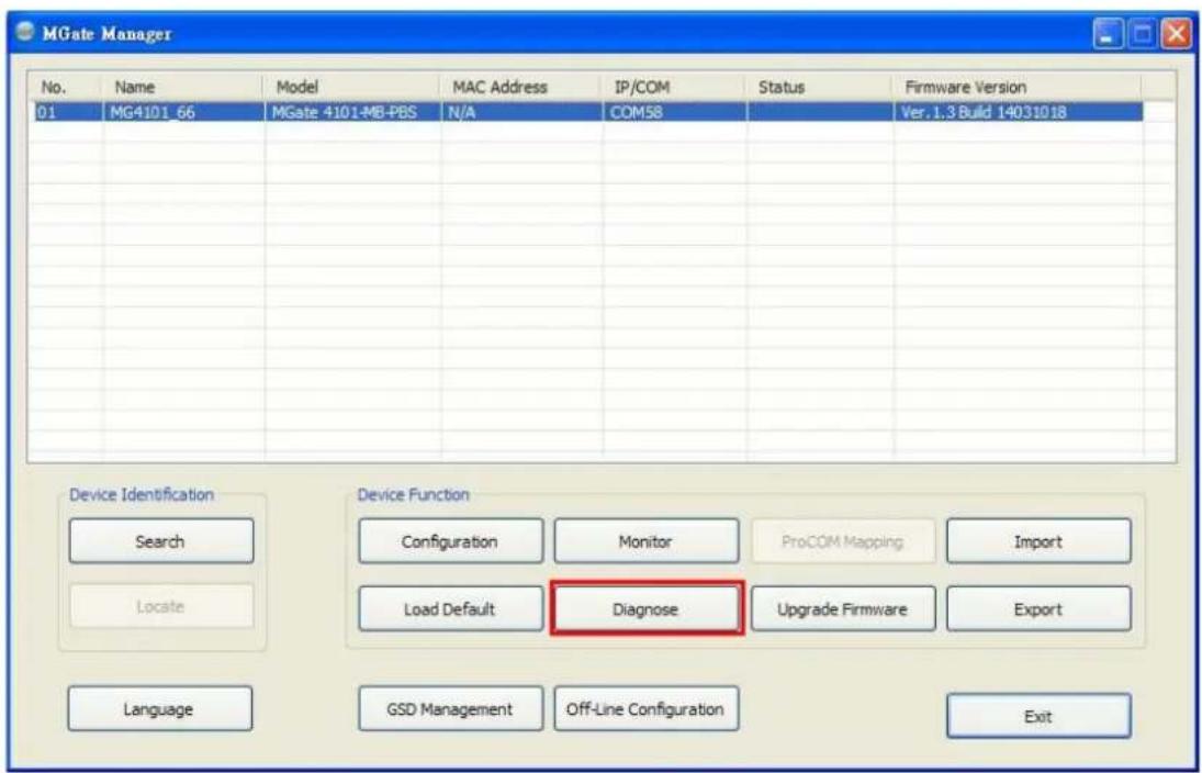
Diagnose is a powerful function to identify communications problems and assist in troubleshooting when setting up a PROFIBUS and Modbus environment. Select the desired unit from the list in MGate Manager and click Diagnose to check the communication status.
text_image
MGate Manager No. Name Model MAC Address IP/COM Status Firmware Version 01 MG4101_66 MGate 4101-MB-PBS N/A COM58 Ver.1.3 Build 14031018 Device Identification Device Function Search Monitor ProCOM Mapping Import Locate Load Default Diagnose Upgrade Firmware Export Language GSD Management Off-Line Configuration ExitThe dialog box will show the details of the communication status of Modbus, PROFIBUS, and I/O Data View. In addition, it contains serial parameters.
| Modbus | PROFIBUS | I/O Data View | |
| Category | Item | Value | |
| Modbus | |||
| State | Running | ||
| Type | RTU Master | ||
| Valid Requests | 4593 | ||
| Exception | 0 | ||
| Timeout | 102 | ||
| CRC/LRC Error | 5 | ||
| Invalid Requests | 0 | ||
| Serial Port | |||
| Port Number | 1 | ||
| Interface | RS485 2-wire | ||
| Settings | 19200, None, 8, 2 | ||
| TX | 45270 | ||
| RX | 33728 | ||
| Break | 0 | ||
| Frame Error | 0 | ||
| Parity Error | 0 | ||
| Overrun Error | 0 | ||
There are two parts. In Modbus tab, the first part is the information regarding Modbus. These details will help you to analyze the Modbus communication.
| Modbus Description | |
| State The communication state of Modbus side | |
| Type RTU Slave / RTU Master / ASCII Slave / ASCII Master | |
| Slave ID The Slave ID for Modbus | |
| Valid Requests | The number of valid requests |
| Exception | The number of exceptions |
| Time-out | The number of time-outs |
| CRC/LRC Error | The number of CRC/LRC errors |
| Invalid Requests | The number of invalid requests |
The second part is the serial parameters. It includes the serial communication about this serial port
| Serial Port Description | |
| Port Number The serial port number | |
| Interface | The serial interface, RS-232/RS-422/RS-485-2w/RS-485-4w |
| Settings | The parameter includes baudrate, parity, start bit and stop bit, for example, 19200, None, 8, 1 |
| Tx The transmission count | |
| Rx | The reception count |
| Break | The number of break signals |
| Frame Error | The number of frame errors |
| Parity Error | The number of parity errors |
| Overrun Error | The number of overrun errors |
The PROFIBUS tab has information about the PROFIBUS status

text_image
Diagnose Modbus PROFIBUS I/O Data View Category Item Value PROFIBUS State Data Exchange Baudrate 1500000 bps Address 3 Output 4 bytes Input 4 bytes Illegal I/O Config 0 Restart Data Excha... 0| PROFIBUS | Description |
| State | The communication state of PROFIBUS side |
| Baudrate | The baudrate of PROFIBUS side |
| Address | The PROFIBUS segment ID |
| Output | The output bytes |
| Input | The input bytes |
| Illegal I/O Config | The number of illegal I/O configurations |
| Restart Data Exchange | The number of restarted data exchanges |
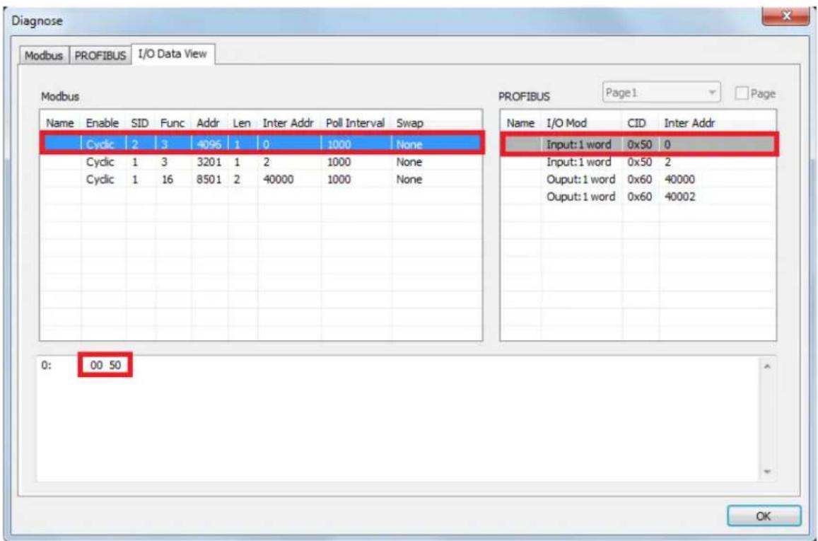
The I/O Data View tab is designed to check all exchanging data in MGate's internal memory. Select PROFIBUS I/O module/ Modbus command to obtain the correct data.
text_image
Diagnose Modbus PROFIBUS I/O Data View Modbus PROFIBUS Page1 Page Name Enable SID Func Addr Len Inter Addr Poll Interval Swap Cyclic 2 3 4096 1 0 1000 None Cyclic 1 3 3201 1 2 1000 None Cyclic 1 16 8501 2 40000 1000 None Input: 1 word 0x50 0 Input: 1 word 0x50 2 Output: 1 word 0x60 40000 Output: 1 word 0x60 40002 0: 00 50 OKUpgrading Firmware
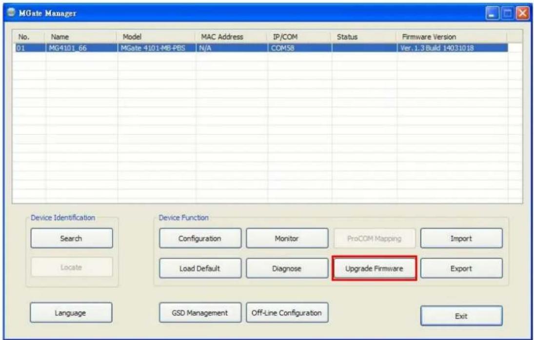
Firmware updates for the MGate 4101-MB-PBS are located at www.moxa.com. After you have downloaded the new firmware onto your PC, you can use MGate Manager to write it onto your MGate 4101-MB-PBS. Select the desired unit from the list in MGate Manager and click Upgrade Firmware to begin the process.
text_image
MGate Manager No. Name Model MAC Address IP/COM Status Firmware Version 01 MG4101_66 MGate 4101-MB-PBS N/A COM58 Ver. 1.3 Build 14031018 Device Identification Device Function Search Monitor ProCOM Mapping Import Locate Load Default Diagnose Upgrade Firmware Export Language GSD Management Off-Line Configuration ExitThe dialog boxes will guide you through the process. You will need to browse your PC for the firmware file. Make sure that it matches your model.
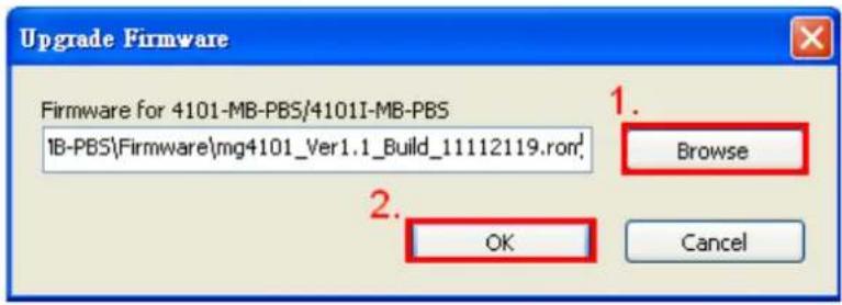
text_image
Upgrade Firmware Firmware for 4101-MB-PBS/4101I-MB-PBS 1B-PBS\Firmware\mg4101_Ver1.1_Build_11112119.ron' 1. Browse 2. OK CancelAs the firmware is written to the unit, progress is displayed in the window.
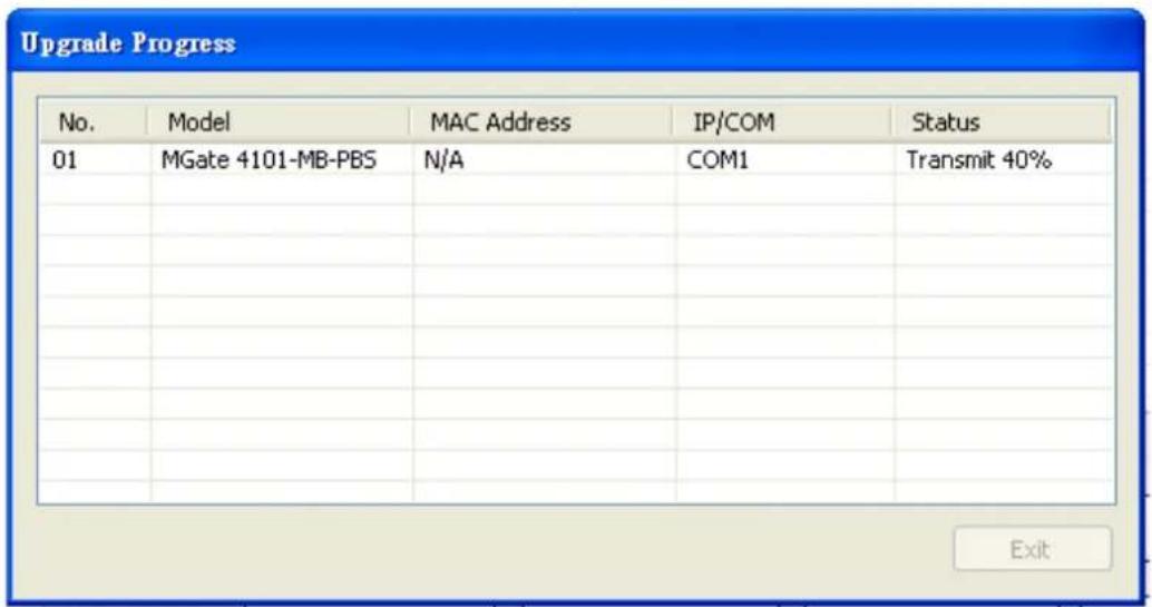
text_image
Upgrade Progress No. Model MAC Address IP/COM Status 01 MGate 4101-MB-PBS N/A COM1 Transmit 40% ExitOnce the firmware has been successfully written onto the unit, click Exit to close the Upgrade Firmware window. MGate Manager will automatically execute a Broadcast Search for all MGate units on the LAN and the recording COM port. Your MGate should reappear in the list of units.
Import/ Export
The Import/Export configuration function is a convenient way to apply the same settings to units which are located in different sites. You can export the configuration as a file, and then import that configuration file onto other units at any time.
The export function saves all the configuration settings and parameters of the MGate 4101-MB-PBS will be saved in an .INI file format. Furthermore, you also can save a GSD file with all I/O module settings in a .zip file.
To begin, click the Export button.
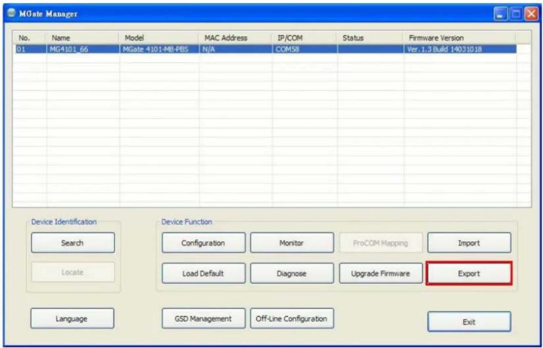
text_image
MGate Manager No. Name Model MAC Address IP/COM Status Firmware Version 01 MG4101_66 MGate 4101-MB-PBS N/A COM58 Ver. 1,3 Build 14031018 Device Identification Device Function Search Monitor ProCOM Mapping Import Locate Load Default Diagnose Upgrade Firmware Export Language GSD Management Off-Line Configuration ExitType in a file name and use the Browse button to set the save file to a specific path. Then, click the OK button.
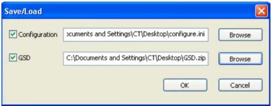
text_image
Save/Load Configuration Documents and Settings\CT\Desktop\configure.ini Browse GSD C:\Documents and Settings\CT\Desktop\GSD.zip Browse OK CancelIf you export the configuration/GSD file successfully, a confirmation message will pop up.
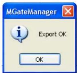
text_image
MGateManager Export OK OKAfter that, the configuration file will be saved as an .INI file
The GSD file will be saved as a .zip file.
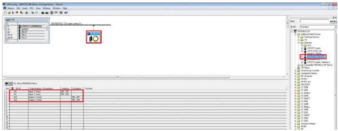
The exported GSD file is used for easy configuration when setting PLC. Typically, users waste lots of time in importing MGate 4101 general GSD files and then set the I/O modules respectively. If we import the specified GSD coming from MGate 4101, a user just needs to pull the module to the PROFIBUS system. Then the I/O modules will be set and you can run the communication. It is an easy and efficient way in PLC configuration.
text_image
AIR Coding - (CREATE AIR System Configuration) - [None] Station Edit Insert PLC View Options Window Help PROVISIONS (F1: drive x 0x10) Control Panel File Edit Control Panel Description Settings Settings Content Control Panel Additional/First Deviation Switching Direction Air Delivery AGI DIP/PC Setup DIP/PC25C Line MEN/PL Network Control Panel DIP/PC Setup, Release 2 Create Before PROVISIONS (F1: drive x 0x10) Control Panel Control Panel Description Settings Settings Content Control Panel Control Panel Description Settings Settings Content Control Panel Description Control Panel Description Control Panel Description Control Panel Description Control Panel Description Control Panel Description Control Panel Description Control Panel Description Control Panel Description Control Panel Description Control Panel Description Control Panel Description Control Panel Description Control Panel Description Control Panel Description Control Panel Description Control Panel Description Control Panel Description Control Panel Description Control Panel Description Control Panel Description Control Panel Description Control Panel Description Control Panel Description Control Panel Description Control Panel Subscription Control Panel Subscription Control Panel Subscription Control Panel Subscription Control Panel Subscription Control Panel Subscription Control Panel Subscription Control Panel Subscription Control Panel Subscription Control Panel Subscription Control Panel Subscription Control Panel Subscription Control Panel Subscription Control Panel Subscription Control Panel Subscription Control Panel Subscription Control Panel Subscription Control Panel Subscription Control Panel Subscription Control Panel Subscription Control Panel Subscription Control Panel Subscription Control Panel Subscription Control Panel Subscription Control Panel Subscription Control Panel Singapore Control Panel Singapore Control Panel Singapore Control Panel Singapore Control Panel Singapore Control Panel Singapore Control Panel Singapore Control Panel Singapore Control Panel Singapore Control Panel Singapore Control Panel Singapore Control Panel Singapore Control Panel Singapore Control Panel Singapore Control Panel Singapore Control Panel Singapore Control Panel Singapore Control Panel Singapore Control Panel Singapore Control Panel Singapore Control Panel Singapore Control Panel Singapore Control Panel Singapore Control Panel Singapore Control Panel Singapore Control Panel Samsung Control Panel Samsung Control Panel Samsung Control Panel Samsung Control Panel Samsung Control Panel Samsung Control Panel Samsung Control Panel Samsung Control Panel Samsung Control Panel Samsung Control Panel Samsung Control Panel Samsung Control Panel Samsung Control Panel Samsung Control Panel Samsung Control Panel SamsungOnce the file is saved, it can be imported into your target unit to duplicate the same settings. Select the target unit first and click the Import button to import.
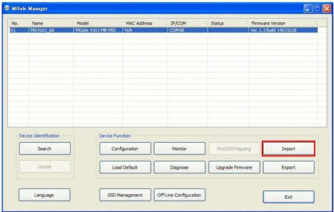
text_image
MGate Manager No. Name Model MAC Address IP/COM Status Firmware Version 01 MG4101 66 MGate 4101-MB-PBS N/A COM58 Ver. 1.3 Build 14031018 Device Identification Device Function Search Configuration Monitor ProCOM Mapping Import Locate Load Default Diagnose Upgrade Firmware Export Language GSD Management Off-Line Configuration ExitSelect the file you want to import, then click the OK button
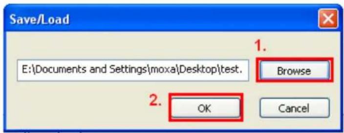
text_image
Save/Load E:\Documents and Settings\moxa\Desktop\test. 1. Browse 2. OK CancelPlease be patient and wait as MGate Manager configures the target device.
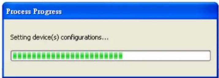
text_image
Process Progress Setting device(s) configurations...If you import the configuration file successfully, a confirmation message will pop up.
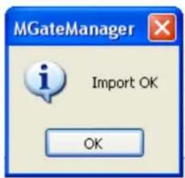
text_image
MGateManager Import OK OKAfter closing the message dialog box, MGate Manager will automatically execute a Broadcast Search for all MGate units on the LAN and the recording COM port. Your MGate should reappear in the list of units.
Off-Line Configuration
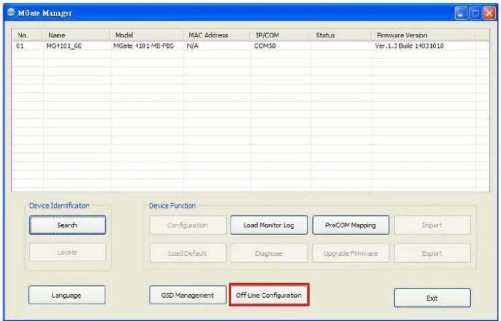
Users can create or modify the configuration file manually through MGate Manager. To use this function, users can click on the Off-Line Configuration button to load the configuration window.
text_image
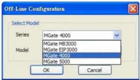
MGate Manager No. Name Model MAC Address IP/COM Status Firmware Version 01 MG4101_66 MGate 1101-MB-PBG N/A COMSB Ver.1.3 Build 14031018 Device Identification Device Function Search Load Monitor Log ProCOM Mapping Import Locale Load Default Diagnose Upgrade Firmware Export Language GSD Management Off-Line Configuration ExitA dialog box will appear. Choose the correct model and series. Click the OK button for the desired MGate device to proceed to the next step.
text_image
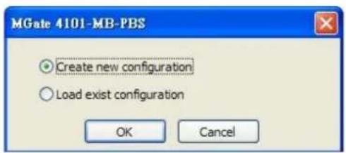
Off-Line Configuration Select Model Series MGate 4000 Model MGate MB3000 MGate EIP3000 MGate 4000 MGate 5000 OK CancelUsers can choose "Create new configuration" or "Load existing configuration" to create or modify configurations.
text_image
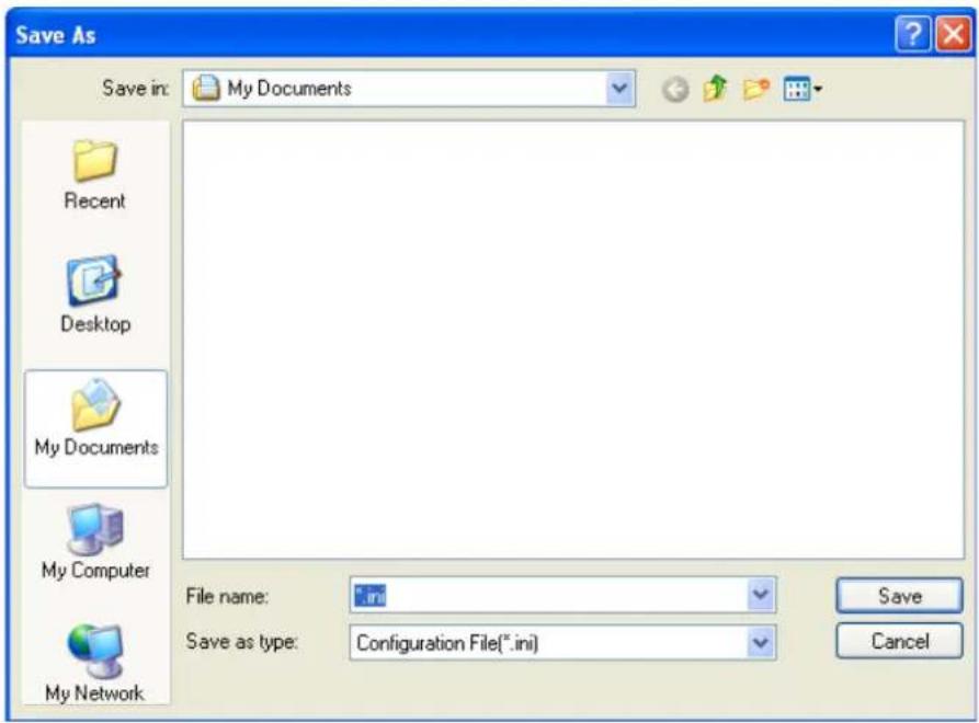
MGate 4101-MB-PBS Create new configuration Load exist configuration OK CancelBy choosing "create new configuration," users can set each function as online setting. Refer to the Modifying the Configuration section for detailed information. When all configurations are finished, click OK to update or store the configuration file.
A dialog box to store the configuration file as *.INI file is displayed.
text_image
Save As Save in: My Documents Recent Desktop My Documents My Computer My Network File name: *.in Save as type: Configuration File(*.ini) Save CancelThe file for "Load existing configuration" can be generated from the Export function, or loaded from the file stored when "Create new configuration."
The following topics are covered in this appendix:
□ Typical Applications
☐ Quick Configuration Steps
□ PROFIBUS Overview
□ Modbus Overview
□ Diagnose Packet Format
Typical Applications
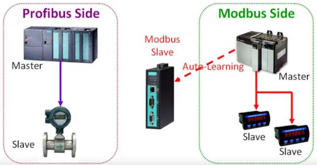
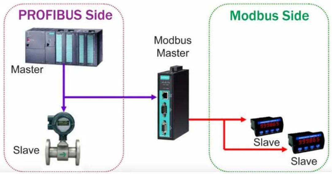
Here is a typical application to demonstrate how to use the Quick Link function and explain how QuickLink works.
First, we are assuming a legacy Modbus master is in the original application, and the Modbus master is running. After MGate 4101-MB-PBS connects to the Modbus master, the MGate 4101-MB-PBS acts as a Modbus slave to learn Modbus requests from the master automatically.
flowchart
graph TD
    A["Profibus Side"] --> B["Master"]
    B --> C["Slave"]
    D["Modbus Side"] --> E["Master"]
    E --> F["Slave"]
    G["Modbus Slave"] --> H["Slave"]
    I["Auto-Learning"] -.-> E
After some time, MGate 4101-MB-PBS will fully learn the requests from the Modbus master. Through this QuickLink process, the MGate 4101-MB-PBS can replace the legacy Modbus master. Moreover, the MGate 4101-MB-PBS can respond to all of the Modbus slaves correctly.
flowchart
graph TD
    A["PROFIBUS Side"] --> B["Master"]
    B --> C["Slave"]
    C --> D["Modbus Master"]
    D --> E["Slave"]
    E --> F["Modbus Side"]
    style A fill:#f9f,stroke:#333
    style F fill:#bbf,stroke:#333
NOTE QuickLink is enabled with the MGate 4101-MB-PBS is in master mode only. Please set the MGate 4101-MB-PBS in master mode before you use the QuickLink function.
Quick Configuration Steps
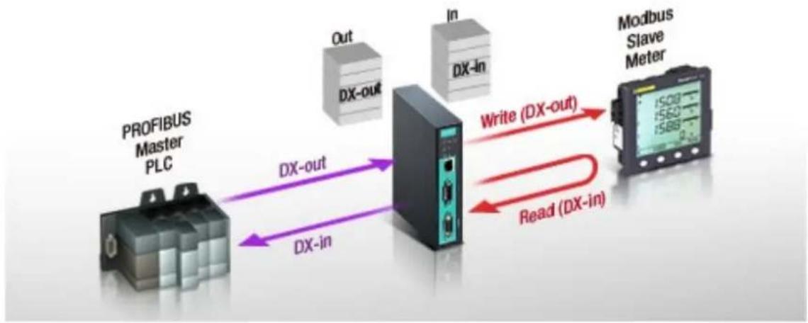
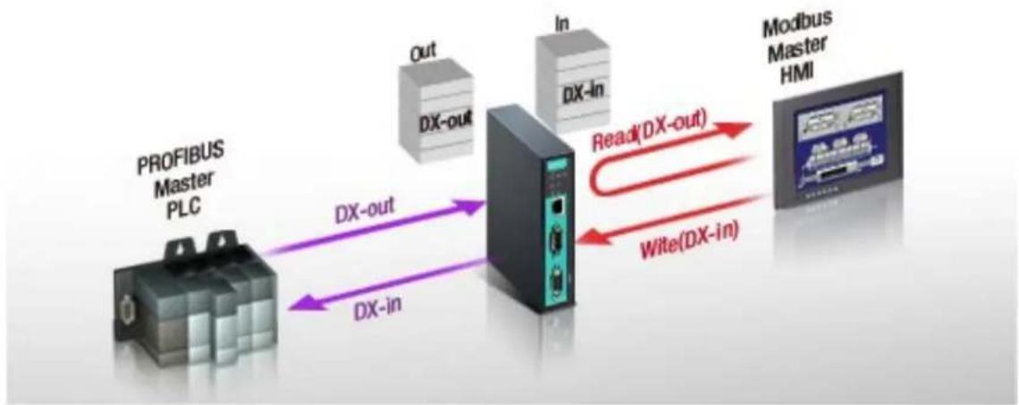
MGate 4101-MB-PBS provides an innovative function which can automatically and quickly finish the configuration. Two typical architectures are illustrated below. Confirm which architecture is used in your application and then follow the steps to finish the configuration.
MGate 4101 is Modbus Master
flowchart
graph LR
    A["PROFIBUS Master PLC"] -->|DX-out| B["Industrial Device"]
    A -->|DX-in| B
    B -->|Write (DX-out)| C["Modbus Slave Meter"]
    B -->|Read (DX-in)| C
    D["Out"] -->|DX-out| B
    E["In"] -->|DX-in| B
    C -->|1500-1580| F["Display"]
    C -->|1580-1580| G["Display"]
MGate 4101 is Modbus Slave
flowchart
graph LR
    A["PROFIBUS Master PLC"] -->|DX-out| B["Modbus Master HMI"]
    A -->|DX-in| B
    B -->|Read(DX-out)| C["In"]
    B -->|Wite(DX-in)| D["Out"]
PROFI BUS Overview
Introduction
PROFIBUS (Process Field Bus) is a standard for fieldbus communication in automation technology and was first promoted in 1989 by BMBF (German department of education and research).
Topology
PROFIBUS uses the bus topology. In this topology, a central line, or bus, is wired throughout the system. Devices are attached to this central bus. One bus eliminates the need for a full-length line going from the central controller to each individual device.
In the past, each PROFIBUS device had to connect directly to the central bus. Technological advancements, however, have made it possible for a new "two-wire" system. In this way, multiple PROFIBUS buses can connect to each other.
MGate 4101-MB-PBS
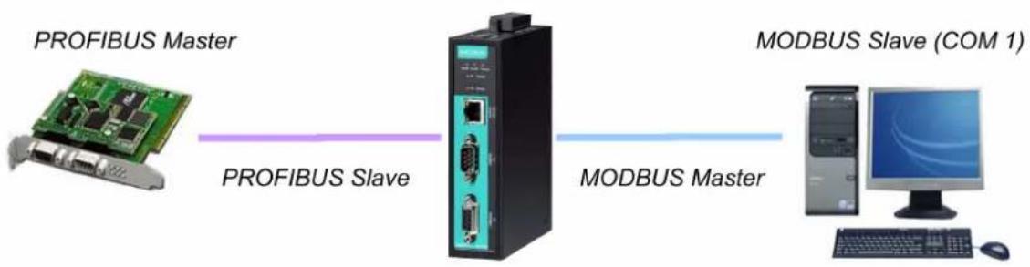
flowchart
graph LR
    A["PROFIBUS Master"] --> B["PROFIBUS Slave"]
    B --> C["MODBUS Master"]
    C --> D["MODBUS Slave (COM 1)"]
Modbus Overview
Introduction
Modbus is one of the most popular automation protocols in the world. It supports both serial and Ethernet devices. Many industrial devices, such as PLCs, DCSs, HMIs, instruments, meters, motors, and drivers, use Modbus as their communication standard.
Devices are Either Masters or Slaves
All Modbus devices are classified as either a master or a slave. Masters initiate all communication with slaves and do not communicate with other masters. Slaves are completely passive and communicate only by sending a response to a master's request.
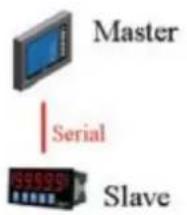
text_image
Master Serial Slave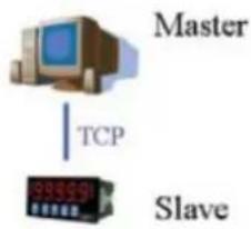
flowchart
graph TD
    A["Master"] -->|TCP| B["Slave"]
    style A fill:#f9f,stroke:#333
    style B fill:#ccf,stroke:#333
Slaves are I identified by ID
Each Modbus slave in a system is assigned a unique ID between 1 and 247. Whenever a master makes a request, the request must include the ID of the intended recipient. Master devices themselves have no ID.
| 0 1~247 248~255 | ||
| Broadcast address | Slave individual address | Reserved |
Communication is by Request and Response
All Modbus communication is by request and response. A master sends a request, and a slave sends a response. The master will wait for the slave's response before sending the next request. For broadcast commands, no response is expected. This is illustrated by the following scenarios:
Normal
The master sends a request to the slave. The slave responds with the requested information.
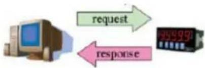
flowchart
graph TD
    A["Computer"] -->|request| B["Digital Display"]
    B -->|response| A
Exception
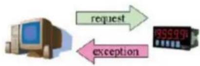
The master sends a request to the slave. The slave may not support the command or an error is detected, so it sends an exception to the master.
flowchart
graph LR
    A["Computer"] -->|request| B["Digital Display"]
    B -->|exception| A
Broadcast
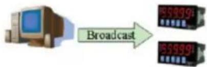
The master sends a broadcast command, such as a reset command. Every slave on the network complies with the command, and no response is sent to the master.
flowchart
graph LR
    A["Computer Icon"] -->|Broadcast| B["Two Broadcast Panels"]
    style A fill:#f9f,stroke:#333
    style B fill:#bbf,stroke:#333
Requests Need a Time Limit
The original Modbus protocol was not designed for simultaneous requests, so only one request on the network can be handled at a time. When a master sends a request to a slave, no other communication may be initiated until after the slave responds. The Modbus protocol specifies that masters use a response timeout function to identify when a slave is nonresponsive due to device or line failure. This function allows a master to give up on a request if no response is received within a certain amount of time. This is illustrated as follows:
Response Timeout
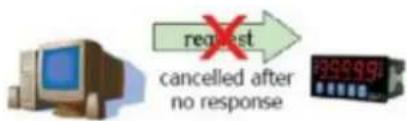
The master sends a request. The slave is unresponsive for the amount of time specified by the response timeout function. The master gives up on the request and resumes operation, allowing another request to be initiated.
text_image
request cancelled after no responseTo allow for a wide range of devices, baudrates, and line conditions, actual response timeout values are left open for manufacturers to determine. This allows the Modbus protocol to accommodate a wide range of devices and systems. However, this also makes it difficult for system integrators to know what response timeout value to use during configuration, especially with older or proprietary devices.
The MGate MB3000 provides a patent-pending function that tests all attached devices and recommends a response timeout value. This function saves considerable time and effort for system integrators, and it results in more accurate timeout settings.
Modbus Ethernet vs. Modbus Serial
Although Modbus is intended as an application layer messaging protocol, the data format and communication rules for Ethernet-based Modbus TCP are different from serial-based Modbus ASCII and RTU.
The major difference between the Ethernet and serial Modbus protocols is the behavior of the communication model. Modbus ASCII and RTU allow only one request on the network at a time. Once a request is sent, no other communication on the bus is allowed until the slave sends a response, or until the request times out. However, Modbus TCP allows simultaneous requests on the network, from multiple masters to multiple slaves. TCP masters cannot send more than one request at a time to a slave, but they can send requests to other slaves before a response is received. The Modbus TCP standard recommends that slaves be able to queue up to 16 requests at a time. The MGate MB3000 will queue up to 32 requests from each TCP master, for up to 16 TCP masters.
Integrate Modbus Serial and Ethernet with Gateways
flowchart
graph TD
    A["HMI"] --> B["Gateway"]
    C["I/O"] --> D["Gateway"]
    E["I/O"] --> D
    F["PLC"] --> D
    B --> G["Device"]
    D --> H["Modbus on TCP/IP"]
    D --> I["Modbus on RS-232/422"]
    D --> J["Modbus on RS-485"]
    K["I/O"] --> L["Device"]
    M["I/O"] --> L
    N["PLC"] --> O["Device"]
    L --> P["Modbus on RS-485"]
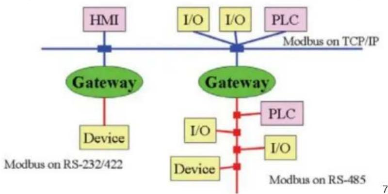
Ordinarily, Modbus TCP and Modbus ASCII/RTU are unable to communicate with each other.
However, with a Modbus gateway in between the Modbus serial network and the Modbus Ethernet network, TCP masters are able to communicate with serial slaves and serial masters are able to communicate with TCP slaves.
Diagnose Packet Format
When the communication of MGate works well between PROFIBUS and Modbus protocols, MGate won't go into diagnostic mode. However, if there is an error in the Modbus connection, for example, a disconnection or no responses, the MGate will continue to send polling requests until three requests are sent without response. Then, it will enter diagnostic mode. In this mode, the MGate will send diagnose packets periodically. Upon receiving the correct response, MGate will go back to normal operations.
Refer to the diagnose packet format table to help identify why the MGate entered diagnostic mode.
| Byte Parameter Notes | ||
| 1 Length | The length of diagnose packet | |
| 2 | Page number | The paging number which the problem data locates |
| 3 | Module | The PROFIBUS IO module number which the problem data locates |
For instance, if the diagnose packet is 03 01 03, that means the problem data is located on the third PROFIBUS IO module in page one. Using this information, you can check if the location of the internal memory is correct.