EX-3516 - Régulateur EXSYS - Free user manual and instructions
Find the device manual for free EX-3516 EXSYS in PDF.


User questions about EX-3516 EXSYS
0 question about this device. Answer the ones you know or ask your own.
Ask a new question about this device
Download the instructions for your Régulateur in PDF format for free! Find your manual EX-3516 - EXSYS and take your electronic device back in hand. On this page are published all the documents necessary for the use of your device. EX-3516 by EXSYS.
USER MANUAL EX-3516 EXSYS
EX-3516 4-Port SATA3 RAID/HyperDuo PCIe(x2) Card
1. Introduction
Thank you for purchasing this 4-Port SATA3 RAID/HyperDuo PCIe Card. It is designed to support up to 4 SATA3 ports in RAID 0 and RAID 1, RAID 0+1 modes and HyperDuo modes for SSD (Solid State Drive) and hard drive combination. It supports SATA3 SSD and hard drives with up to 6.0Gbps data rate. It is an ideal solution to add new SATA3 SSD and hard drives for your system.
Features:
√ Supports 1-lane 5.0Gb/s PCI Express Gen.2 Data Transfer Rate
√ Built-in 4 Internal SATA3 Ports
√ Supports RAID 0,1, 0+1 and HyperDuo (Safe or Capacity) Modes
√ Supports Windows based RAID GUI (Marvell Storage Utility, MSU)
√ Supports SATA3 transfer rate up to 6.0Gb/s (600Mbytes/sec)
√ Supports RAID 1 Rebuild by BIOS Setup Utility
√ Supports Windows 2003, 2008, XP, Vista and Win 7
2. Board Layout
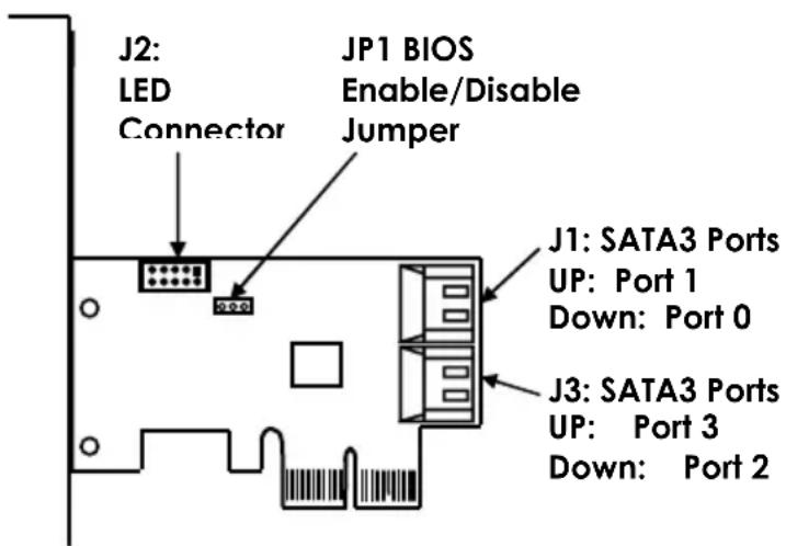
text_image
J2: LED Connector JP1 BIOS Enable/Disable Jumper J1: SATA3 Ports UP: Port 1 Down: Port 0 J3: SATA3 Ports UP: Port 3 Down: Port 23. Jumper Settings
The JP1 can be used to disable the BIOS on the card for some critical applications, please leave the jumper at "ENA" all the time.
JP1: BIOS Enable/Disable Jumper
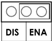
BIOS Enabled:
Jumper Installed at "ENA" (Default)
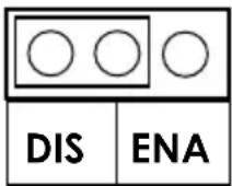
BIOS Disabled:
Jumper Installed at "DIS"
4. Hardware Installation
- Power down the computer, remove the computer cover.
- Choose an unused PCI Express bus slot (2, 4, 8 or 16 lane), unscrew and remove the slot cover.
- Place the SATA3 RAID PCIe Card into the slot. Carefully press the board into the slot until it seats firmly.
- Secure the SATA3 RAID PCIe Card with the slot cover screw.
- Install the SATA cables from the SATA connectors to your SATA devices.
- Carefully reinstall the computer cover. Insert and tighten the computer cover screws.
- Power up the PC and observe the monitor. The BIOS lists all Serial ATA devices attached to the SATA3 RAID/HyperDuo PCIe Card. For example:
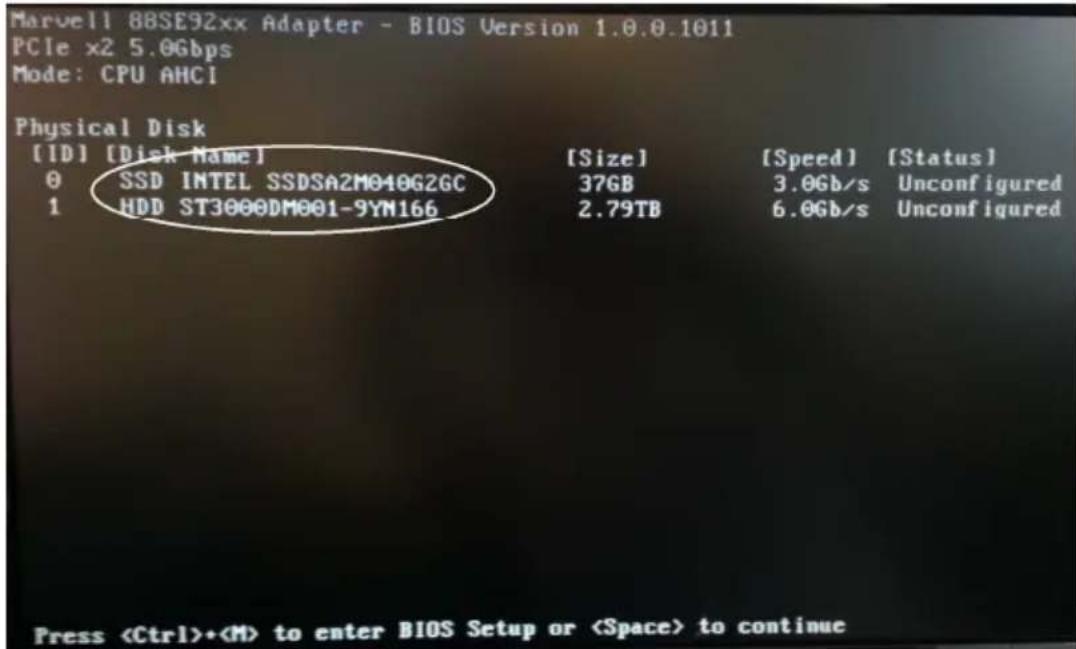
text_image
Marvell 88SE92xx Adapter - BIOS Version 1.0.0.1011 PCIe x2 5.0Gbps Mode: CPU AMCI Physical Disk [ID] [Disk Name] [Size] [Speed] [Status] 0 SSD INTEL SSDSA2M040G2GC 37GB 3.0Gb/s Unconfigured 1 HDD ST3000DM001-9YM166 2.79TB 6.0Gb/s Unconfigured PressIf the information displayed on your monitor is correct (the installed devices are listed with the correct device name, etc.), congratulations! You have successfully installed the SATA3 RAID/HyperDuo PCIe Card in your computer. If you want to configure your RAID drives, press and hold the 2 keys, Ctrl and M, to enter the BIOS Setup Utility for this card. You can configure the SATA RAID or HyperDuo modes in the BIOS Setup.
5. RAID and HyperDuo Modes
5.1 RAID Modes
This chapter will help you to know the RAID and HyperDuo modes supported by the SATA3 RAID/HyperDuo PCIe Card.
5.2 Non-RAID mode (Single Disk Mode)
This mode is the Single Disk mode. Each disk drive will be treated as one disk volume in the operating system.
5.3 Striping (RAID 0)
Read and write sectors of data interleaved between multiple drives. When any disk member fails, it affects the entire array. Performance is better than a single drive since the workload is balanced between the array members. This array type is for high performance systems. Identical drives are recommended (but not necessary, if the sizes differ, it will truncate the bigger drive so the sizes match, it will cause a waste) for performance as well as data storage efficiency. The disk array data capacity is equal to the number of drive members times the smallest member capacity.
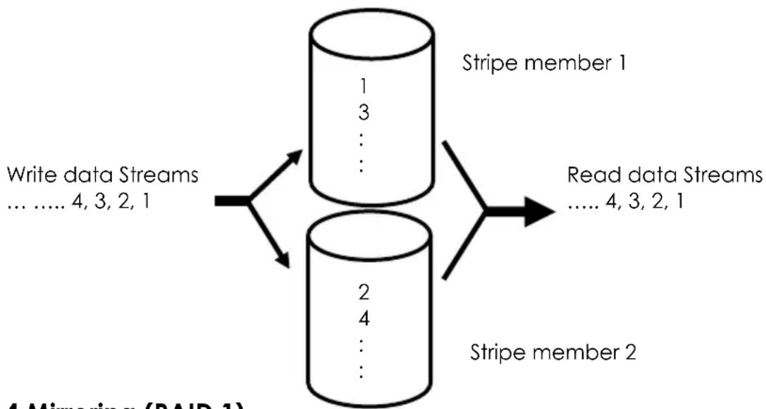
flowchart
graph TD
    A["Write data Streams ... 4, 3, 2, 1"] --> B["Stripe member 1"]
    C["Read data Streams ... 4, 3, 2, 1"] --> D["Stripe member 2"]
    B --> E["Write data Streams ... 4, 3, 2, 1"]
    D --> F["Write data Streams ... 4, 3, 2, 1"]
5.4 Mirroring (RAID 1)
Writes duplicate data on to a pair of drives while reads are performed in parallel. The RAID controller performs reads using advanced data handling techniques that distribute the workload in a more efficient manner than using a single drive. When a read request is made, the RAID controller selects the drive positioned closest to the requested data, then looks to the “idle” drive to perform the next read access. If one of the mirrored drives suffers a mechanical or did not respond, the remaining drive will continue to function.
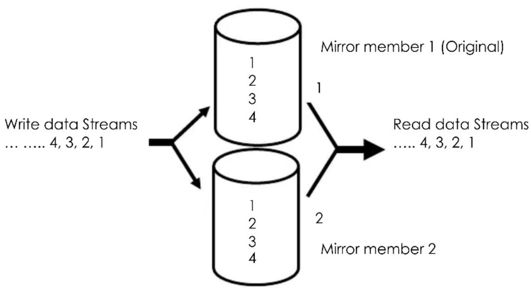
flowchart
graph TD
    A["Write data Streams ... 4, 3, 2, 1"] --> B["Mirror member 1 (Original)"]
    B --> C["Read data Streams ... 4, 3, 2, 1"]
    A --> D["Mirror member 2"]
    D --> E["2"]
    B --> F["1"]
    D --> G["1"]
    B --> H["1"]
    D --> I["1"]
5.5 Striping/Mirroring (RAID 0+1, or RAID 10)
A combination of both above array types. It can increase performance by reading and writing data in parallel while protecting data with duplication. With a four-drive disk array,
two pairs of drives are striped. Each pair mirrors the data on the other pair of striped drives. The data capacity is similar to a standard mirroring array with half of total capacity dedicated for redundancy.
5.6 HyperDuo
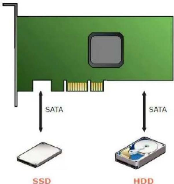
The HyperDuo mode in combination with a SATA HDD and a SSD, offering a breakthrough embedded technology for new-generation 6Gb/s SATA controllers, enabling 80 percent of the performance of a solid state drive (SSD) at one-third the cost. Configured with one hard drive and one SSD, HyperDuo uses intelligent algorithms to automatically migrate hot data to the SSD, while enabling all data to be safely stored on a larger capacity SATA HDD.
text_image
SATA SSD SATA HDDHyperDuo enables two modes: Safe Mode and Capacity Mode. Both modes automatically identify LBA ranges across both the SSD and HDD so that the user experience is exactly the same. By allowing consumers to view the same single drive volume (eg. Data (D:) ) as they do today, HyperDuo requires no behavioral changes by consumers to maximize simplicity and eliminates user error.
5.6.1 HyperDuo: Safe Mode
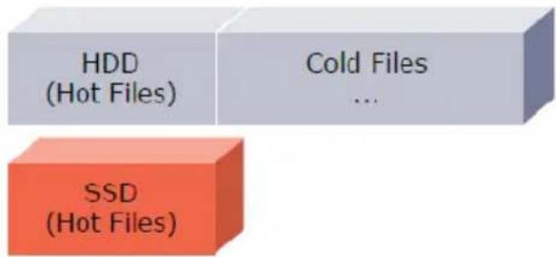
Safe Mode provides optimal data protection by mirroring data from the SSD to the hard disk for maximum resiliency.
Safe Mode - Mirror SSD Data To HDD
text_image
HDD (Hot Files) Cold Files ... SSD (Hot Files)5.6.2 HyperDuo: Capacity Mode
Capacity Mode augments SSD and HDD capacity for the most cost-effective configuration.
Capacity Mode – Add SSD and HDD Capacities Together

text_image
SSD (Hot Files) HDD (Cold Files)MRU periodically scans for hot and cold files at the file system level.
6. Configuring a SATA Disk Array
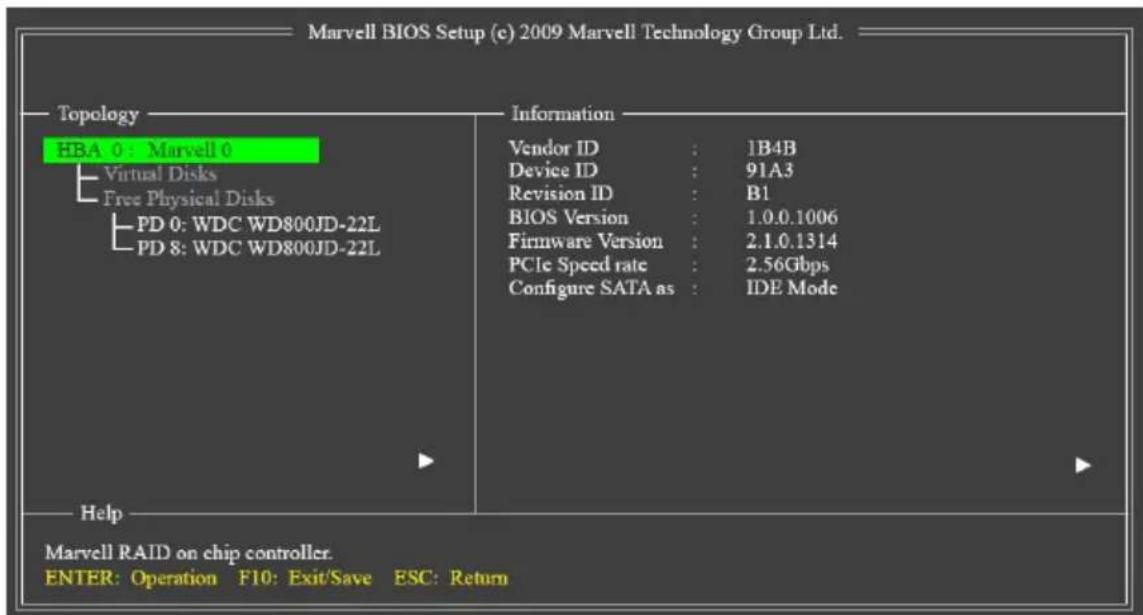
Turn on your computer and press
text_image
Marvell BIOS Setup (c) 2009 Marvell Technology Group Ltd. Topology HBA 0 : Marvell 0 Virtual Disks Free Physical Disks PD 0: WDC WD800JD-22L PD 8: WDC WD800JD-22L Information Vendor ID : 1B4B Device ID : 91A3 Revision ID : B1 BIOS Version : 1.0.0.1006 Firmware Version : 2.1.0.1314 PCIe Speed rate : 2.56Gbps Configure SATA as : IDE Mode Help Marvell RAID on chip controller. ENTER: Operation F10: Exit/Save ESC: Return6.1 Create a Disk Array:
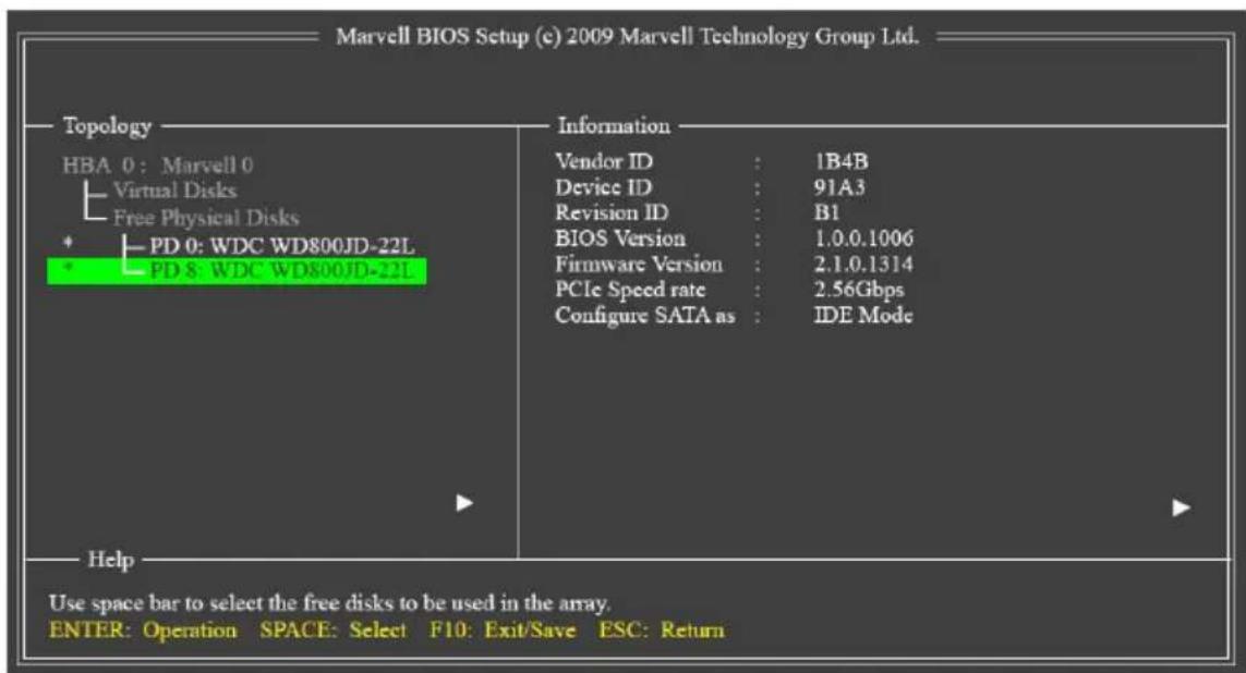
Under Free Physical Disks, use the
text_image
Marvell BIOS Setup (c) 2009 Marvell Technology Group Ltd. Topology HBA 0: Marvell 0 Virtual Disks Free Physical Disks PD 0: WDC WD800JD-22L PD 5: WDC WD800JD-22L Information Vendor ID : 1B4B Device ID : 91A3 Revision ID : B1 BIOS Version : 1.0.0.1006 Firmware Version : 2.1.0.1314 PCIe Speed rate : 2.56Gbps Configure SATA as : IDE Mode Help Use space bar to select the free disks to be used in the array. ENTER: Operation SPACE: Select F10: Exit/Save ESC: ReturnTo further configure the disk array, use the up or down arrow key to move the selection bar to select an item in the right block of the screen and press
-
RAID Level: Select a RAID level. Options include RAID 0 (Stripe) and RAID 1 (Mirror).
-
Stripe Size: Select the stripe block size. Options include 32 KB and 64 KB.
-
Gigabyte Rounding: Select whether to permit the installation of a replacement drive that is smaller than the failed drive when performing a RAID 1 rebuild. Options include None, 1G, and 10G.
-
Quick Init: Select whether to quickly erase old data on the hard drives when creating the array.
-
VD Name: Enter an array name with 1\~10 letters (letters cannot be special characters).
-
Next: After completing the settings above, move to Next and press
to begin creating the array. When prompted to confirm whether to create this array, press to confirm or to cancel. -
When completed, you can see the new array under Topology\Virtual Disks.
-
Save the Settings and Exit. After you complete the RAID configuration and before you exit the configuration screen, be sure to press
in the main screen. Press to confirm or to cancel. -
Now, you may proceed to create the SATA driver diskette (for AHCI mode) and the installation of the SATA driver and operating system
6.2 Delete the Disk Array:
To deleted the existing array, select the array on the main menu (example: VD 0: New_VD) and press
7. Installing RAID Drivers and GUI (MSU)
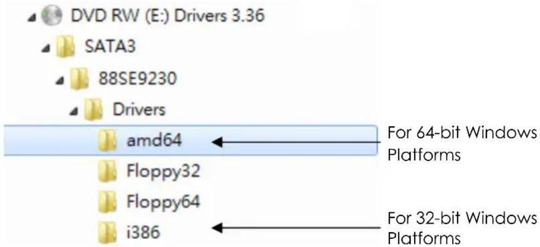
With the Marvell Storage Utility (RAID GUI), you can setup a disk array or view the current array status in the operating system. Before installing the MSU utility, you have to install the drivers first, the Windows Hardware Installing Wizard will invoke the drivers when you first time power up the system with the RAID card installed in the PCIe slot, you need to insert the supplied driver CD (folders as the following picture), and browse to the correct folder to complete the installation.
text_image
DVD RW (E:) Drivers 3.36 SATA3 88SE9230 Drivers amd64 Floppy32 Floppy64 i386 For 64-bit Windows Platforms For 32-bit Windows PlatformsPlease follow the following steps:
-
While Windows Hardware Wizard asking for the drivers, browse to the correct folder \SATA3\88SE9230\Drivers\amd64 (or i386 for 32-bit Windows) to install the RAID drivers
-
Reboot the system to let the drivers take effect.
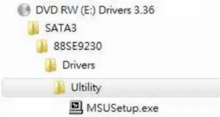
- Run the RAID GUI installer
(\SATA3\88SE9230\Utility\MRUSetup.exe) to install the RAID Utility.
text_image
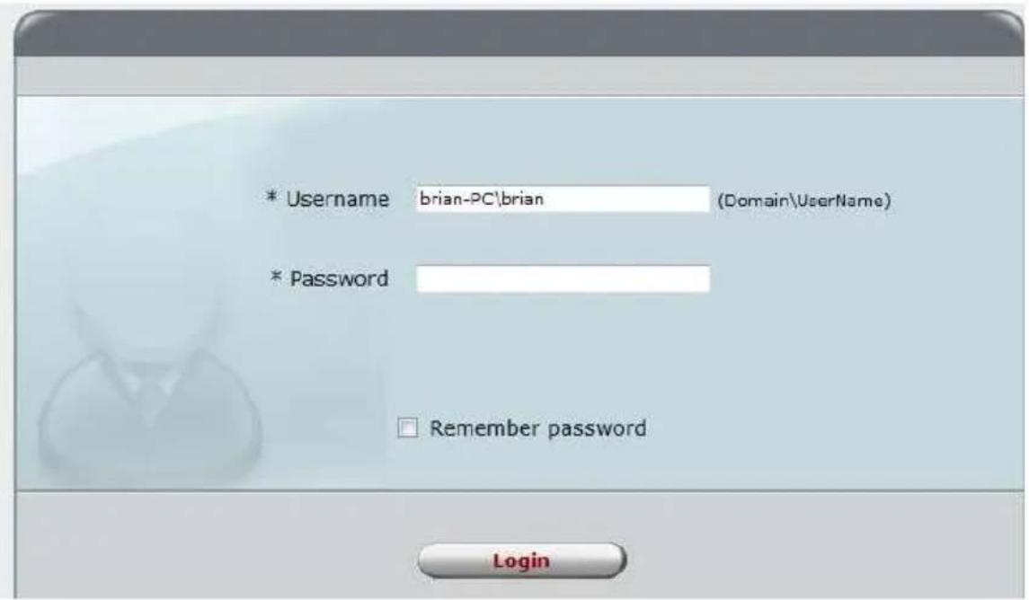
DVD RW (E:) Drivers 3.36 SATA3 88SE9230 Drivers Utility MSUSetup.exeNote: After the installation, you must login the utility with the same account name and password that you use to login the operating system. If you did not set the account password before, click Login to enter the Marvell Storage Utility (MSU) directly.
text_image
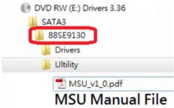
* Username brian-PC\brian (Domain\UserName) * Password Remember password LoginNote: Please refer to the manual file of Marvell Storage Utility (MSU) on the CD (in the same folder as the drivers) for more detail operations.
text_image
DVD RW (E:) Drivers 3.36 SATA3 88SE9130 Drivers Ultility MSU_v1_0.pdf MSU Manual File8. Troubleshooting Tips
Q: What should I do if my disk array is broken?
If a disk array is broken, please don't open the computer case immediately to correct the problem before you backup all your important data. It's because you are most likely to make a mistake in this abnormal condition.
PLEASE BACKUP YOUR DATA FIRST!
If your array is in RAID 1 mode or HyperDuo Safe mode, that means your system is still running in the critical condition instead of dead. If you backup your data by removable drives or network solution, you will have a copy of up-to-date data away from this computer. Then you are safe to correct the RAID problems even you open the computer case or change the hardware settings. Some people destroyed the data on the good drive by accident mistake when they are changing drive or cables or modes. And they lost their important data since they did NOT backup them first! For RAID 0 mode, please always backup the data since you will lost all data when the array is broken.
Some broken array is caused by the connection problems. To see if it is the problem, please power off your computer and check the cable connections between the RAID card and SSD or hard drives. Or change a new power or SATA cable, then power on the computer again. These may bring the broken array back to normal if the root cause is the connection problem.
If the above actions don't work, then it may be the SSD or hard drive problem. Please replace the defect drive with a good one. The RAID card then will detect the new drive and rebuild the broken array (RAID 1). Please note that you cannot rebuild a broken RAID 0 in any case.