EX-6051POEIS - Wi-Fi repeater EXSYS - Free user manual and instructions
Find the device manual for free EX-6051POEIS EXSYS in PDF.


| Type | Wi-Fi Repeater / Range Extender |
| Brand | EXSYS |
| Model | EX-6051POEIS |
| Connectivity | 802.11 b/g/n, single-band 2.4 GHz |
| Max Speed | 300 Mbps |
| PoE Support | Yes, IEEE 802.3af compliant |
| Ethernet Ports | 1x 10/100 RJ45 |
| Antenna | 2x internal omnidirectional |
| Range (Outdoor) | Up to 100 meters (open area) |
| Power Consumption | 5W (max) |
| Dimensions (L x W x H) | 82 x 58 x 22 mm |
| Weight | 0.1 kg |
| Operating Temperature | 0°C to 40°C |
| LED Indicators | Power, LAN, WLAN |
| Wireless Encryption | WEP, WPA/WPA2-PSK |
| WPS Button | Yes |
| Reset Button | Yes (hold 10s) |
| Package Contents | Repeater, PoE injector, quick installation guide |
| Maintenance | Clean with dry, soft cloth; avoid liquids |
| Safety Warnings | Do not expose to water or moisture; keep away from children |
| Certifications | CE, FCC, RoHS |
Frequently Asked Questions - EX-6051POEIS EXSYS
User questions about EX-6051POEIS EXSYS
0 question about this device. Answer the ones you know or ask your own.
Ask a new question about this device
Download the instructions for your Wi-Fi repeater in PDF format for free! Find your manual EX-6051POEIS - EXSYS and take your electronic device back in hand. On this page are published all the documents necessary for the use of your device. EX-6051POEIS by EXSYS.
USER MANUAL EX-6051POEIS EXSYS
RS-422/485 to Ethernet / IP
natural_image
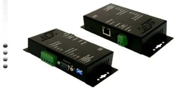
Two black electronic devices with green connectors and I/O ports, no visible text or symbols on the devices themselves.EXSYS
V1.0 07.07.11
IndexIndex
- INTRODUCTION 3
- CONNECTOR LAYOUT 3
- SWITCH SETTINGS 4
- HARDWARE INSTALLATION 5
- INSTALLATION DER IP ADRESSE 4
- VIRTUAL COM SOFTWARE 7
5.1 Beschreibung der Virtual COM Software 7
5.2 Installation der Virtual COM Software 7
5.3 Konfiguration des Anschlusses 9 - ANSCHLÜSSE 12
- TECHNISCHE DATEN 12
1. Introduction
Thank you for purchasing this 1-port RS422/485 to Ethernet Adapter (hereinafter referred to as "Adapter"). It provides an ideal solution to control RS422/485 serial devices over Internet instantly. It supports TCP Server Mode, TCP Client Mode and UDP and COM Port Modes that are compatible with the standard network API (Winsock or BSD Sockets). It provides a web browser console to change its settings by Internet Browser easily. Features:
√ Provides 1 RS422/485 Port over Ethernet
√ Provides 1 DB9 Male and 1 Terminal Block Connectors
√ Provides Different Models: Isolation & Surge Protection(IS), Power over Ether (PoE) and both (PoEIS)
√ RS422/485 Baud Rate from 300bps to 115.2Kbps
√ Provides one 10/100Mbps, RJ45 LAN Port
√ Supports Auto Cross Over Feature for Ethernet Cable
√ Provides TCP Server, TCP Client, and UDP and COM Port Modes
√ Optional DIN RAIL Mounting Kit
√ Flexible Power Source: +7\~40 VDC from DC Jack
- Connector Layout
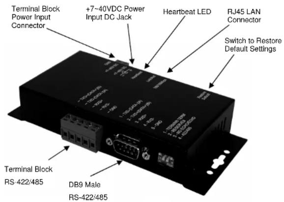
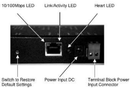
- Switch to Restore Default Settings: This switch can be used to reset the product to its factory default settings. Press the switch by either a pen or similar tool will restore the default settings immediately.
• DC Jack Power Connector: A 12V/2A AC adapter is supplied with this product. - RJ45 Ethernet Connector: 10/100Mbps Ethernet port. It supports auto cross-over feature. You can use the same cable to connect to either a Hub/Switch or a host computer.
• LED Indicators: There are a heartbeat LED and 2 LAN LEDs on the rear panel. They are described as the following table:
| LED Name | Color LED | Function |
| Heartbeat | Green | Blinking: Normal operationElse: Malfunction |
| Link/Act LED | Green | Steady on: LinkedBlinking: Transferring data |
| 10/100Mbps | Amber | Steady on: Linked in 100Mbps modeOff: Linked in 10Mbps mode |
3. Switch Settings
- RS485 User: Since the factory settings are initially set at 2-wire RS485 mode. There is no need to change any switch settings from the default settings.
- RS422 User: Change the mode pin to the "422" position (ON). Keep the other settings unchanged.
After clicking to the bottom „Add“ a new Windows will open. Here are the various inputs to the EX-6051 will be made.
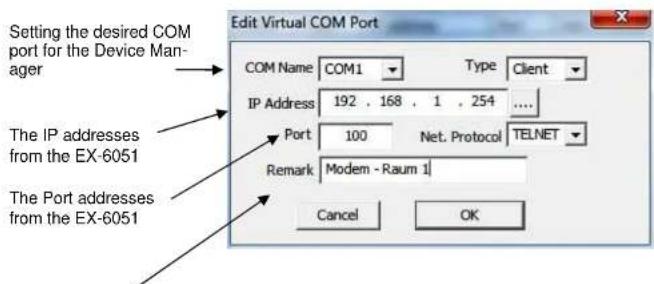
By „Remark“ you can write your personally information where the Box are installed for example: Modem - Room 1; then you click to OK.
Switch Description:
| Switch Pin# | Switch Name(Switch States) | Switch Positions | Description |
| 1 | TERM/NO TERM(ON/OFF) | TERM | Termination Resistor is Enabled |
| NO TERM(Default) | Termination Resistor is Disabled | ||
| 2 | RVD | ON(Default) | Reserved for Future Use |
| OFF | Reserved for Future Use | ||
| 3 | NO ECHO/ECHO(ON/OFF) | NO ECHO(Default) | No echo data |
| ECHO | Transmitting data will be echoed back | ||
| 4 | 422/485(ON/OFF) | 422 | 4-wire RS422 mode |
| 485(Default) | 2-wire RS485 mode |
- Please note that if the mode were set at "422" mode, the ECHO setting will take no effect.
- The Echo mode is useful for the application program to detect if the RS485 bus were in a collision. If the echoed data was not equal to the transmitted data, then the bus was in a collision.
4. Hardware Installation
- Use static electricity discharge precautions. Remove possible static discharge potential from any objects that the Adapter may come in contact with before installation. This can be accomplished by touching a bare metal chassis rail after you have turned off the power.
- Attached the power adapter. For the PoE model, you don't have to connect any AC power adapter since the product will get the power from the Ethernet cable. In this case, please make sure your switching hub is PoE type that can act as a PSE (Power Source Equipment).
- Connecting LAN cable: Use a standard straight-through Ethernet cable to connect to a Hub or Switch. If you connect the Adapter to your computer's Ethernet port instead, you don't need to change to a cross-over type cable since the Adapter provides auto cross-over feature.
- Connect the Adapter's serial port to your serial devices.
- Use the DIN RAIL mounting Kit (optional) if you want to place the product on the industrial DIN RAIL.
5. Configuring the Adapter
Setting IP Address
Please consult your Network Administrator to determine the appropriate IP address. The IP address can be set in any of the following ways:
• Automatically from a DHCP Server
Web Browser
• Ethernet Managing utility (Em.exe supplied by this product)
The Adapter comes with factory installed IP address 192.168.1.254. It is ready to accept a new IP address from a DHCP Server. If your network has a DHCP server, it will automatically assign an IP address to the Adapter the first time it is connected and powered up.
1. Setting the IP address from a DHCP Server
A DHCP server will automatically assign an IP address (dynamic address) as well as Subnet Mask and Gateway to this Adapter. If you power up the Adapter without a fixed (static) IP address, the DHCP server will be able to assign an IP address (Note: the default setting is Disable DHCP, if you want to support DCHP, please Enable it first.).
If you will set the IP address using another method, the address becomes static. This was done when you Disable the DHCP setting (default) in the Setup Menu of the Adapter.
2. Setting the IP address using Web Browser
Please make sure your PC's IP address is set at the same subnet of the Adapter. If not, you usually need to change your PC's IP address from "Local Area Connection Properties", here is an example to show you how to change your PC's IP address:

Seite 6eite
Seite Seite
5. Virtual Com Software
5.1 Description Virtual COM Software
The Centossec_Setup.exe is a Microsoft Windows-based software for configuration of Virtual COM ports. For start the Centossec_Setup.exe software, insert first the included driver CD to your CD-Rom drive and open the directory „IO_over IP/Drivers/Serial_IP“. Start the program with „Administrator“.
5.2 Installation CentosSEC Virtual Com Software
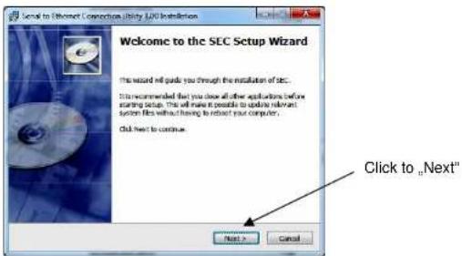
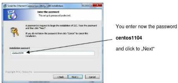
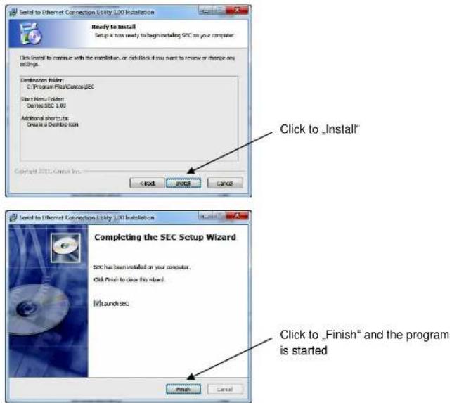
The software is now installed. Always confirm with „Next“
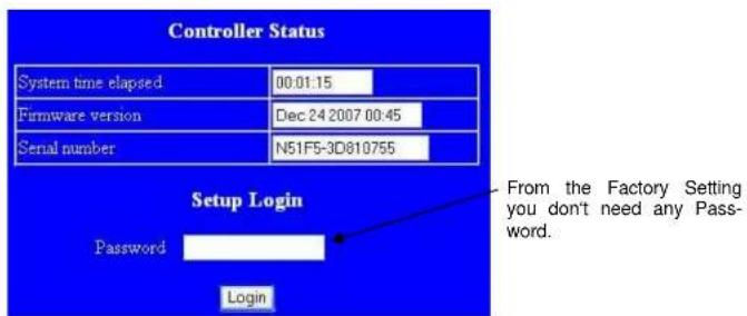
Run your browser and access the product by entering the default (192.168.1.254) or current IP address into your browser's address window. Enter the password (default has no password). Then go to change your IP address as well other parameters if required.
3. Setting the IP address using Em.exe Utility
The Em.exe is a Microsoft Windows based utility to find all the Adapters connected on the same subnet and network segment. To run the Em.exe utility, please insert the driver CD supplied with the Adapter. Open (double click) the program at the following location (assume the CD-ROM drive is at E):
E:\IO_over_IP\Utilities\Em\Em.exe


Note: Some firewall and anti-virus programs may block the Em.exe utility to search over network. In this case you may need to change their settings to allow the Em.exe to action for network searching. Windows also allow you to disable their firewall if you need. You can disable it temporarily while you are running the Em.exe.
4. The Adapter Settings
When you entered Setup Menu of the Adapter, the following page will be available for your access. Please click Update button after you changing your settings. Please also remember your password because you need it when you are going to enter this setup menu next time
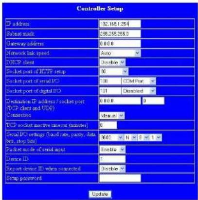
| Item Description | |
| IP address | 4 numbers separated by dots, it can be assigned by the DHCP server if enabled. |
| Subnet mask | 4 numbers separated by dots, can be assigned by the DCHP server if enabled. |
| Gateway address | 4 numbers separated by dots, can be assigned by the DCHP server if enabled. |
| DHCP client | If disable, then IP address · Subnet mask and Gateway address must be assigned manually. |
| Socket port of HTTP setup | If disable, then IP address, Subnet masks and Gateway address must be assigned manually. |
| Socket port of serial I/O | Port Number : any number between 1 and 65536, except 80 and 81 (which have been designated as the web pages)Socket Type :TCP Server, uses TCP protocol, passively waits for Client.TCP Client, uses TCP protocol, actively connects to Server.UDP Client, uses UDP protocol, exchanges packets with Server without connection. |
| Socket port of digital I/O | Spared function for the future expansion. No function at this model. |
| Destination IP address/ Socket port(TCP client and UDP) | The Server IP address under TCP client or UDP client mode. |
| Serial I/O settings ( baud rate, parity, data bits, stop bits ) | Baud Rate : 300 – 115200 bpsParity Bits : No Parity, Evon. OddData Bits: 5, 6, 7, 8Stop Bit : 1 or 2 |
| Interface of serial I/O RS232 | |
| Packet mode of serial input | If packet mode is disabled, the data received from the serial port will be transmitted immediately with minimal delay. If packet mode is enable, the data will be saved in the buffer memory first, and transmitted when the entire packet is received or when the buffer memory is full |
| Packet mode inter-packet timeout | In packet mode, the time constant used to determine if the packet is finished, acceptable range is 10 to 1000 ms. |
| Device ID User assigned device ID number, acceptable range is 0 to 65535. | |
| Report device ID when connected | If this function is enabled, the device will report the device ID after the socket is connected. The format is :Serial I/O socket nnnnnA[LF][CR]Digital I/O socket nnnnnB[LF][CR]There are eight bytes : nnnnn is the 5-digit device ID. [LF] is decimal 10, and [CR] is decimal 13 |
| Setup password | The login password can be empty or 1 to 15 characters long. If the password is empty then no password is required for login. |
- RS-422/485 to Ethernet / IP
- IndexIndex
- Introduction
- Switch Settings
- Hardware Installation
- Configuring the Adapter
- Setting IP Address
- Setting the IP address from a DHCP Server
- Setting the IP address using Web Browser
- Virtual Com Software
- Description Virtual COM Software
- Setting the IP address using Em.exe Utility
- The Adapter Settings
Brand : EXSYS
Model : EX-6051POEIS
Category : Wi-Fi repeater