
500-28/C - Chauffe-eau instantané et chaudière BUDERUS - Free user manual and instructions
Find the device manual for free 500-28/C BUDERUS in PDF.


User questions about 500-28/C BUDERUS
0 question about this device. Answer the ones you know or ask your own.
Ask a new question about this device
Download the instructions for your Chauffe-eau instantané et chaudière in PDF format for free! Find your manual 500-28/C - BUDERUS and take your electronic device back in hand. On this page are published all the documents necessary for the use of your device. 500-28/C by BUDERUS.
USER MANUAL 500-28/C BUDERUS
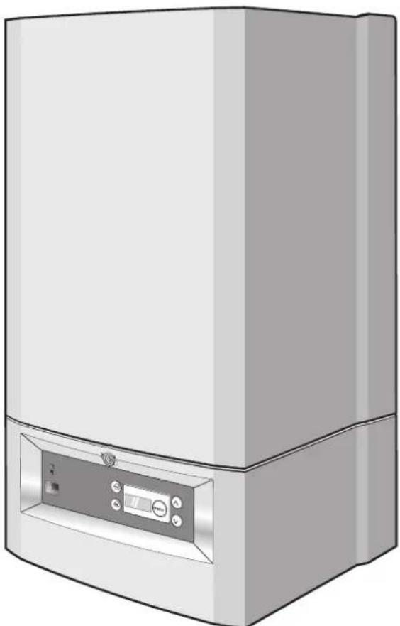
Gas wall hung Boiler condensing
Buderus 500 - 24/C
Buderus 500 - 28/C
natural_image
Illustration of a rectangular electronic device with a control panel and indicator lights (no text or symbols visible)benchmark
Introduction
Please read these instructions and follow them carefully for a safe and economical use of your combi boiler.
Important general instructions for use
This device should only be used for its intended purpose and in accordance with the regulations.
It is a requirement and in your own interest, and that of safety that this boiler must be installed by a CORGI registered installer, in accordance with the relevant requirements of the current Gas Safety (Installation and Use) Regulations, The Building Regulations, current I.E.E. Wiring Regulations and the relevant British Standard Codes of Practise.
The device may only be used in combination with the units, accessories and spare parts listed in the installation and maintenance instructions.
Other combinations of units, accessories and consumables are only to be used if they completely fulfil the specifications involved, and if system performance and safety are not affected in any way.
Subject to technical modifications
As a result of our policy of constant development, there may be small differences with respect to illustrations, functional steps and technical data.
Cleaning
For normal cleaning simply dust with a dry cloth. To remove stubborn marks and stains, wipe with a damp cloth and soap and finish off with a dry cloth.
DO NOT use abrasive cleaning materials.
G. C. Appliance No.:
Buderus 500-24/C : 47-110-04
Buderus 500-28/C : 47-110-03
Contents
1 Safety precautions.... 4
2 Installation area / boiler room.... 4
3 Working in the heating system.... 4
4 Functions of the system and operating instructions 4
5 Maintenance intervals .... 4
6 Conversion to LPG 4
7 Abbreviations 4
8 Permanent clearances.... 5
9 DBA 6
10 Initial start-up 7
10.1 Preparing for operation 7
10.2 Operational and fault codes 9
11 Taking the system out of service ..... 10
11.1 Draining the system in case of frost..... 10
Preface
Dear Customer,
Your Buderus 500 Series wall-mounted condensing gas combi boiler has been designed and built in accordance with state-of-the-art technological standards and the recognised safety rules. Special focus has been placed on operator convenience in this respect.
Carefully read the safety instructions and operating manual to ensure safe, economic and ecologically beneficial use of the unit.
Due to the high efficiency of the boiler a plume of water vapour may form at the terminal during operation. This is normal.
1 Safety precautions

DANGER!
If you smell gas:
- No naked flames! Do not smoke!
- Avoid sparks! Do not operate electrical switches. Do not use the telephone, plug-in devices of any kind or the doorbell!
- Shut off the main gas supply!
- Open windows and doors!
- Warn building occupants and evacuate the building!
- Call the gas distributor (under 'GAS' in the telephone directory) from outside the building!

NOTE
In the event of any other type of incident, shut off the main gas supply and electric supply to the appliance and seek assistance from a CORGI registered engineer.
2 Installation area / boiler room

DANGER!
The air intake and outlet openings must not be reduced in size or closed.

DANGER!
Do not store or use inflammable materials or liquids near the heating boiler.

NOTE
To prevent the boiler from being damaged, care must be taken not to contaminate the combustion air with halogenated hydrocarbons (e.g. contained in aerosol sprays, solvents, detergents, paints, and adhesives), or with high quantities of dust. The room in which the boiler is installed must be frost-proof and be well ventilated.
3 Working in the heating system

DANGER!
Only a CORGI registered Engineer is to be entrusted with the installation of this boiler, the gas supply and the flue connection. Commissioning, Servicing and any Repairs must be carried out by a competent person i.e.: a CORGI Registered Engineer. All CORGI Registered Installers carry a CORGI identification card and have a registration number. Both should be recorded in your boiler logbook. You can check if your installer/Engineer is registered by telephoning 01256 372300 or by writing to: CORGI, 1 Elmwood, Chineham Business Park, Crockford Lane, Basingstoke. RG24 8WG.

NOTE
The heating boiler is designed exclusively for heating water as part of a central heating system and/or hot-water system.
It is recommended to enter into a service contract with a specialist company.
4 Functions of the system and operating instructions
The installer should familiarize the user with the functions and operation of the heating system and ensure that a complete set of technical documentation is supplied.
5 Maintenance intervals
For optimum, long-term reliable functioning of the heating boiler, and in order to be able to claim under the terms of the manufacturer's warranty, the heating boiler must be inspected and maintained at least once a year (under normal operating conditions) by an officially recognized installation and service engineer. The term "normal operating conditions" means that the heating boiler is used to provide central heating and/or hot water to no more than one single-family dwelling.
In all other cases, the heating boiler must be inspected and maintained by an officially recognised installation service engineer every 2,500 burner operating hours.
6 Conversion to LPG
The boiler is suited for natural gas. To convert the boiler to LPG you must contact a CORGI registered fitter.
7 A b b r e v i a
DBA = Control unit (Dedicated Burner Automat)
MCW inlet = Mains Cold Water inlet
DHW outlet= Domestic Hot Water warm outlet
CH flow = Central Heating flow
CH return = Central Heating return.
8 Permanent clearances
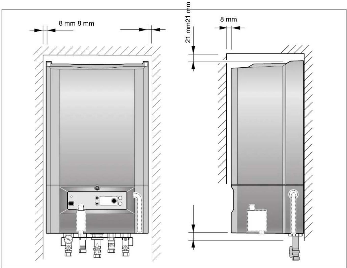
The boiler must be located in an area with the following permanent clearances.
text_image
8 mm 8 mm 21 mm21 mm 8 mm
NOTE
The permanent clearances do not change if a wall spacing frame is used.
The installer or service engineer must be able to create sufficient service clearences. These clearences should have been considered at time of installation.
9 DBA
The boiler is equipped with a DBA. This is the internal control of the boiler. The DBA is located behind the access panel.
The DBA allows you to operate the boiler and to make adjustments in its settings.
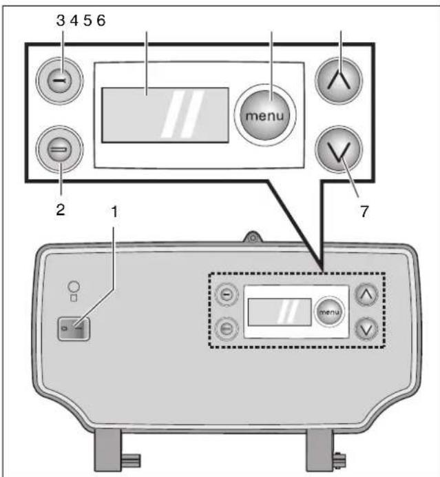
DBA overview:
1. Mains switch (see fig. 1)
Use this switch to turn the boiler on or off.
2. Reset button "B" (see fig. 1)
When a blinking code is in the display, it is possible to try and restart the boiler by pressing this button.

NOTE
It is not possible to reset the boiler when there is no fault code blinking in the display.
3. Service Button "A" (see fig. 1)
Is used for servicing purposes only.
DO NOT use this button!
4. Display (see fig. 1)
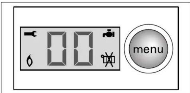
The display visualizes settings, adjustments and fault codes (see fig. 2).
5. Menu button "E" (see fig. 1)
The menu button "E" allows you to scroll through the menu items.
Pressing the E button once, the current warm start function setting is displayed.
Pressing the E button again gives the current DHW temperature setting is displayed.
Pressing the E button again gives the current setting of summer operation.
Pressing the E button once more gives the current CH flow temperature setting.
6. and 7. Up "C" and Down "D" keys (see fig. 1)
These keys can be used for adjusting temperatures and activating or de-activating certain summer operation.
The C key when pressed gives the current operating status of the boiler. Press the D key once to display the current DHW flow in l/m.
text_image
3 4 5 6 menu 2 1 7fig. 1 DBA
item 1: mains switch
item 2: "reset" button
item 3: "service" button
item 4: display
item 5: "menu" button
item 6: adjusting arrow up
item 7: adjusting arrow down
text_image
00 menufig. 2 DBA display
10 Initial start-up
10.1 Preparing for operation
Please also note the user manual supplied with the external time controls and thermostat.
10.1.1 Check water pressure
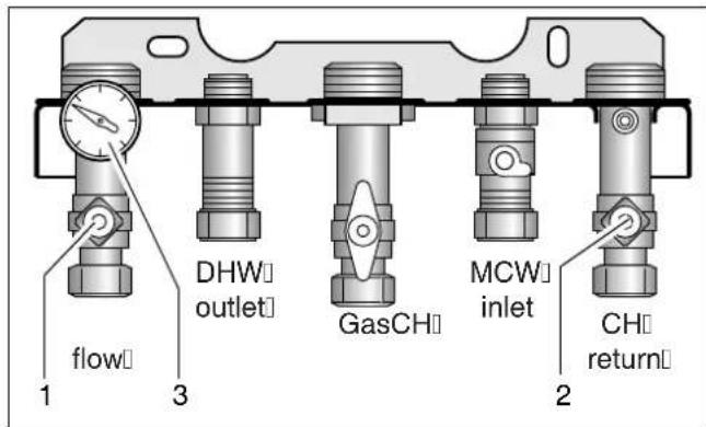
- Check the pressure gauge (fig. 3, item 3) located at the bottom of the boiler for the current system pressure. Optimum system pressure is 1.5 bar.
10.1.2 Topping up the heating system

WARNING!
The wall-mounted condensing gas combi boiler must not be activated at this stage.
The system should be filled with untreated mains water.
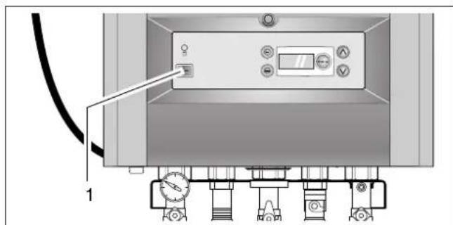
- Turn off the boiler by setting the mains switch to "0".
- If necessary open the CH flow and CH return servicing valves (fig. 3, item 1 and 2).
text_image
DHW outlet GasCH MCW inlet CH return flow 1 3 2fig. 3 Servicing valves
text_image
Technical diagram of a mechanical or electrical device with labeled components and a pointer indicating a control panel.fig. 4 DBA - Mains switch
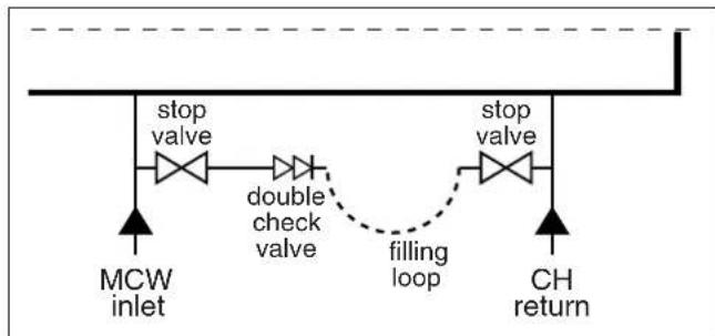
- Connect filling loop (accessory) (fig. 5).
- Open both stop valves (fig. 5).
- Fill the system to a pressure of approx. 1.5 bar (fig. 3, item 3).
● Shut both stop valves. - Disconnect the filling loop.
● Vent all radiators from air starting with the lowest radiator and working your way up to the highest point. - Check the pressure after venting. If the pressure has dropped under 1.0 bar then top up the system as described previously.
- Disconnect the filling loop and cap off.
flowchart
graph TD
    A["MCW inlet"] --> B["stop valve"]
    B --> C["double check valve"]
    C --> D["filling loop"]
    D --> E["stop valve"]
    E --> F["CH return"]
fig. 5 Filling loop

NOTE
If there are frequent water losses, have the system examined and repaired by a CORGI registered installer. Have the inhibitor concentration checked every year.
10.1.3 Temperature-setting adjustments
Setting the warm start function
- Press E button once.
- Use the C and D keys to turn the warm start function on or off (table 1). Factory setting: warm start function is "on".
Setting the domestic hot water (DHW) temperature
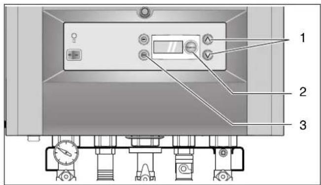
- Press E button (see fig. 6, item 2) twice then adjust the DHW temperature to the desired temperature (40 °C - 60 °C) using the C and D keys (see fig. 6, item 1). Factory setting is 48 °C.
Setting the boiler to summer operation
When you want to make sure that your boiler will not operate for central heating in the summer then you can set the boiler to summer operation. The boiler will then only operate for DHW.
- Press the E button (see fig. 6, item 2) three times. The current setting blinks.
- Use the C and D keys to adjust to desired setting.
| Central heating is on | |
 | Central heating is off (summer operation).DHW is still available |

NOTE
When summer operation is active then the boiler will not operate for central heating until summer operation has been deactivated.
Setting the flow temperature for CH
- Press E button (see fig. 6, item 2) four times then adjust the flow temperature to the desired temperature (30 °C – 80 °C) using the C and D keys (see fig. 6, item 1). Factory setting is 80 °C.
It is not possible to set the flow temperature when the boiler is set to summer operation.
| Setting Meaning | |
| H - ECO / cold start | More energy efficient, less chance of calcification, longer waiting periods. |
| I - comfort / warm start | Maximum comfort due to short waiting period for warm water. Not as energy efficient as the cold start and there is more chance of calcification. |
table 1 Warm start function
text_image
Technical diagram of a pressure control device with labeled components and control buttonsfig. 6 DBA - control panel
10.2 Operational and fault codes
Operating conditions and possible faults can be seen, pressing the C key.
All codes not contained in table 2 should be noted down separately. These are malfunctions that require the presence of a CORGI installer.
| Display after pressing service button | Meaning Rectification | |
| 0A, 0C, 0E, 0H, 0L, 0U, 0Y | Boiler is ready for operation | |
| 6A | Burner not ignited | Press Reset button B (fig. 6, item 3). If the burner fails to ignite after several unblocking operations, consult a CORGI installer. |
| - H | Normal heating mode | Maximum comfort when set at 60 °C |
| =H | Normal hot water mode |
table 2 Operational and fault codes
11 Taking the system out of service
- Push the mains power switch (fig. 4, item 1) to "0".
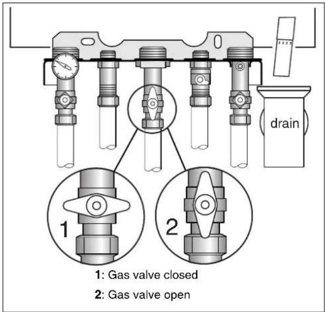
- Close the gas service valve by turning it clockwise (fig. 7, item 1).
Frost protection
The boiler has an automatic frost protection. When the CH flow temperature drops below 7 °C then the boiler will start up.
text_image
drain 1: Gas valve closed 2: Gas valve openfig. 7 Gas service valve
11.1 Draining the system in case of frost
It is not recommended, but if the boiler needs to be shut down for a longer period of time, then it is necessary to drain the system. Especially when there is a chance for frost conditions.
- Turn off the boiler by setting the mains power to "0" (fig. 4, item 1).
- Close the gas valve (fig. 7, item 1).
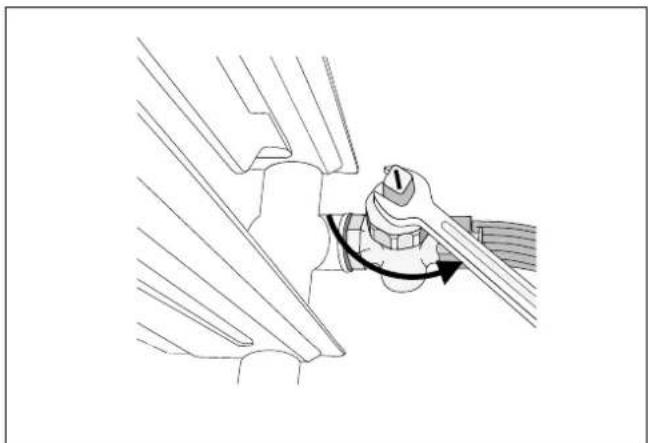
- Drain the system at its lowest point using the stop valves or radiator (see fig. 8). The automatic air vent at the system's highest point must be open.
natural_image
Technical line drawing of a mechanical assembly with a hand operating a workpiece (no text or symbols)fig. 8 Draining the system
Buderus
Heating system specialist:
Buderus
Cotswold Way
Warndon
Worcester
WR4 9SW
Telephone: 01905 - 752 936
Fax: 01905 - 753 130
Customer Services: Tel: 0870 - 421 5933
Technical Product Support: Tel: 0870 - 421 5944
Sales: Tel: 01905 - 752 640 Fax: 01905 - 456 445 / 455 394
Returns: Tel: 01905 - 752 531 Fax: 01905 - 455 392
Spares: Tel: 01905 - 752 576 Fax: 01905 - 754 620
www.buderus-domestic.co.uk
Buderus is a trading name of BBT Thermotechnology UK Ltd.