Greenstar 21i System - Chauffe-eau instantané et chaudière Worcester - Free user manual and instructions
Find the device manual for free Greenstar 21i System Worcester in PDF.


User questions about Greenstar 21i System Worcester
0 question about this device. Answer the ones you know or ask your own.
Ask a new question about this device
Download the instructions for your Chauffe-eau instantané et chaudière in PDF format for free! Find your manual Greenstar 21i System - Worcester and take your electronic device back in hand. On this page are published all the documents necessary for the use of your device. Greenstar 21i System by Worcester.
USER MANUAL Greenstar 21i System Worcester
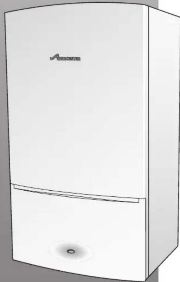
Wall hung RSF gas fired condensing system boiler
Greenstar i System ErP
For sealed central heating systems
natural_image
Illustration of a white refrigerator with a logo and ventilation grille (no text or symbols on the device itself)6720806946-00.1Wo
These appliances are for use with: Natural Gas or L.P.G. (Cat. II 2H 3P type C13, C33 & C53)
| Model GC Number | ||
| Natural Gas | Greenstar 9i System ErP | 41-406-21 |
| Greenstar 12i System ErP | 41-406-23 | |
| Greenstar 15i System ErP | 41-406-25 | |
| Greenstar 18i System ErP | 41-406-27 | |
| Greenstar 21i System ErP | 41-406-29 | |
| Greenstar 24i System ErP | 41-406-31 | |
| L.P.G. Greenstar | 9i System ErP | 41-406-22 |
| Greenstar 12i System ErP | 41-406-24 | |
| Greenstar 15i System ErP | 41-406-26 | |
| Greenstar 18i System ErP | 41-406-28 | |
| Greenstar 21i System ErP | 41-406-30 | |
| Greenstar 24i System ErP | 41-406-32 | |
If you smell gas:
▶ Well away from the building: call the National Gas Emergency Service on 0800 111 999.
L.P.G. boilers: Call the supplier's number on the side of the gas tank.
UK/IE

text_image
benchmark COLLECTIVE MARK THE MARK OF QUALITY FOR THE INSTALLATION, COMMISSIONING AND SERVICING OF DOMESTIC HEATING AND HOT WATER SYSTEMSPreface
Please read these instructions carefully
These instructions are applicable to the Worcester, Bosch Group appliance model stated on the front cover only.
These instructions apply in the UK/IE only and must be followed except for any statutory obligation.
After installation please leave this User instruction Manual, Installation, Commissioning and Servicing Instructions and completed Benchmark Checklist with the user.
Dedicated to heating comfort
Thank you for purchasing a Greenstar gas-fired condensing appliance manufactured by Worcester, Bosch Group. The company prides itself on manufacturing appliances to the strictest quality control standards throughout every stage of production.
Worcester, Bosch group has led the field in innovative appliance design and performance for over 50 years. This heritage means all our products are of exceptional quality and proven reliability.
The Greenstar range in particular is extremely energy efficient, offering you economical running costs and value for money. It is amongst the top energy rated appliances available.
There is also the reassurance of our parts and labour guarantee - backed up by Worcester Total Cover, an optional complete maintenance scheme to keep your appliance operating at peak condition and efficiency.
Contents
1 Key to symbols and safety instructions ..... 4
1.1 Key to symbols 4
1.2 Safety precautions 4
2 General information....5
2.1 Energy efficiency 5
2.2 Servicing 5
2.3 Benchmark standard 5
2.4 User caution 5
3 Controls 6
3.1 Appliance controls 8
3.1.1 Appliance display 9
3.1.2 Basic adjust mode 12
3.2 Central heating 13
3.2.1 View appliance flow set temperature ..... 13
3.2.2 Setting the appliance flow temperature for the system .....13
3.2.3 Set economic temperature - Central heating....14
3.2.4 Turning the central heating off during the summer 14
3.2.5 Appliance frost protection 14
3.3 No integral diverter valve fitted: Cylinder temperature adjustment .....15
3.4 Optional integral diver valve kit fitted: Setting the cylinder hot water temperature ..15
3.4.1 View the cylinder hot water temperature set temperature .....15
3.4.2 General cylinder hot water temperature adjustment .....16
3.4.3 Mid point domestic hot water temperature .. 16
3.4.4 Domestic hot water eco and preheat modes . 17
3.4.5 Domestic hot water preheat mode manual activation (Eco mode off)....17
3.4.6 Turn off the operation/fault diagnostic light (blue)....17
4 System pressure 18
4.1 External filling link 18
5 Clearances.... 19
6 Maintaining your appliance 20
7 Fault finding 20
7.1 Appliance alert state 22
7.2 Appliance reset 22
7.3 Extreme cold weather 23
8 Fault or breakdown 23
9 Tips on energy saving 24
10 Environment/disposal 25
11 Your guarantee 25
12 Glossary 26
1 Key to symbols and safety instructions
1.1 Key to symbols
Warnings

Safety instructions in this document are framed and identified by a warning triangle which is printed on a grey background.
The following keywords are defined and can be used in this document:
- NOTICE indicates a situation that could result in damage to property or equipment.
- CAUTION indicates a situation that could result in minor to medium injury.
- WARNING indicates a situation that could result in severe injury or death.
- DANGER indicates a situation that will result in severe injury or death.
Important information

This symbol indicates important information where there is no risk to people or property.
Additional symbols
Symbol Meaning
| 1. a numbered step in an action sequence | |
| ▶ a step in an action sequence | |
| → a reference to a related part in the document or to other related documents | |
| 1 | a reference number to identify or refer to a part or item |
| • | a l i s t |
| – a list entry (second level) | |
Table 1
Examples of additional symbols used
A numbered step in an action sequence
A sequence of numbered steps or actions carried out in a specific order to complete a task.
- First action
- Second action
- Third action etc.
A step in an action sequence
A sequence of defined actions or steps carried out in order to complete a task.
▶ Action
▶ Next action
etc
A reference to a related part in the document or to other related documents.
To refer the reader to a specific figure/table/section within the manual.
→ e.g. figure 1.
A reference number to identify or refer to a part or item.
In a related figure, items or parts identified by a sequential number.
List entries, first and second levels
• A single component/item
- A component/list, made up of multiple parts/items.
- Sub component or sublist of main component/list.
- e t c .
1.2 Safety precautions
If you smell gas:
A gas leak could potentially cause an explosion. If you smell gas, observe the following rules.
▶ Prevent flames or sparks:
- Do not smoke, use a lighter or strike matches.
- Do not operate any electrical switches or unplug any equipment.
- Do not use the telephone or ring doorbells.
▶ Turn off the gas at the meter or regulator.
▶ Open windows and doors.
▶ Warn your neighbours and leave the building.
▶ Prevent anyone from entering the building.
▶ Well away from the building: call the National Gas e Emergency Service on 0800 111 999. y
L.P.G. boilers: Call the supplier's number on the side of the gas tank.
Appliance operation:
This appliance can be used by children aged from 8 years and above and persons with reduced physical, sensory or mental capabilities or lack of experience and knowledge, if they have been given supervision or instruction concerning the use of the appliance, in a safe way, and understand the hazards involved.
Children shall not play with the appliance.
Cleaning and user maintenance shall not be made by children without supervision.
Combustible and corrosive materials:
Chemically aggressive substances can corrode the appliance and invalidate any guarantee.
- Do not store or use any combustible materials (paper, thinners, paints, propellants, cleaning agents etc.) inside the cupboard containing the appliance or within the vicinity of the appliance.
Fittings and modifications:
Only a competent engineer can remove the appliance case and carry out any work, in accordance with the Gas Safety (Installation and Use) Regulations.
- Do not remove the appliance case.
Any misuse or unauthorised modifications to the appliance, flue or associated accessories and heating system will invalidate the guarantee.
- Do not modify the appliance or flue system in any way.
Worcester, Bosch Group accepts no liability arising from any such actions. This does not affect your statutory rights.
Cleaning the appliance case:
Use a damp, soft cloth to clean the outer painted metal case of the appliance, do not use chemicals or abrasive materials.
2 General information
2.1 Energy efficiency
Energy efficiency information is given in the Installation, Commissioning and Servicing Instructions supplied with the appliance.
2.2 Servicing

Ensure that the service engineer completes the Service Record in the Benchmark Checklist after each service. The Benchmark Checklist and service interval record can be found at the rear of the Installation, Commissioning and Servicing Instructions.
- The appliance must be serviced regularly by a competent, qualified person, such as a Worcester service engineer or other Gas Safe registered engineer.
- Always use original spares, to help maintain the efficiency, safety and reliability of the appliance and have the Service Record completed in the Benchmark Checklist.
The completed Benchmark Checklist will be required in the event of any guarantee work and may be required by the local Building Control Inspector.
2.3 Benchmark standard

The Benchmark initiative is a code of practice to encourage the correct installation, commissioning and servicing of domestic central heating appliances and system equipment.
A “checklist” is dispatched with every appliance and can be found towards the back of the Installation, Commissioning and Servicing Instructions. This is a vital document that needs to be completed by the installer at the time of installation. It confirms that the appliance has been installed and commissioned according to the manufacturer's instructions.
The service record provides space for the recording of regular servicing of the appliance/heating system and this can become a valuable document when, for example, you wish to sell the property. The service record will show a potential purchaser that the heating system has received regular professional maintenance and servicing during its lifetime.
The Benchmark initiative aims to:
- Raise standards among professional installers
• Build and maintain high safety standards in the industry - Improve customer satisfaction levels
• Make a contribution to the nation's commitment to climate change
2.4 User caution
- It is forbidden for any interference with the appliance other than those actions allowed in this document.

CAUTION: Incorrect use
▶ Any incorrect use can result in danger to the householder.
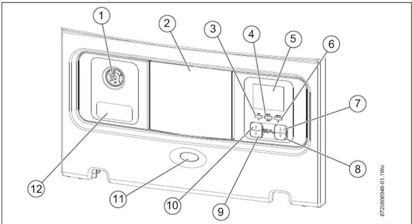
3 C o n t r o l s
text_image
1 2 3 4 5 6 7 8 9 10 11 12 6720806946-01.1WoFig. 1 Appliance control panel
| Item Description | |
| 1 | S y s t e m p r e s s u r e g a u g• Displays pressure in the heating system and appliance |
| 2 Position for optional programmer• Worcester plug in controls position | |
| 3 | E C O / O K b u t t o n• Dual function button- ECO (toggles domestic hot water preheat ON/OFF)- O K ( m e n u c o n f i r m a t i o n ) |
| 4 Info/Return/Spanner button• Multi function button- Info (Information menu access)- Return (return to previous screen)- Spanner (engineer function) | |
| 5 Appliance display• Temperature and information display | |
| 6 Reset/Service engineer button• Dual function button- Reset (appliance reset)- Service engineer (engineer service and set up function) | |
| 7 Cylinder hot water settings increase temperature/menu scroll up buttonDual function button- Increase temperature (increase the desired hot water temperature), this function is only available if the optional integral diveter valve kit is fitted.- Menu scroll up (scroll upwards through menu items) | |
| 8 Cylinder hot water settings decrease temperature/menu scroll down buttonDual function button- Decrease temperature (decrease the desired hot water temperature), this function is only available if the optional integral diveter valve kit is fitted.- Menu scroll down (scroll downwards through menu items) | |
| 9 Central heating settings decrease buttonDecrease temperature (decrease the desired flow temperature) | |
| 10 Central heating settings Increase button/Increase buttonIncrease temperature (increase the desired flow temperature) | |
| 11 Heat requirement demand and fault indicator (blue)Dual function- Heat requirement demand (illuminates during a central heating or hot water requirement demand)- Fault indicator (flashes during a fault condition) | |
| 12 Appliance identification labelDetails on appliance model, serial number and gas council number | |
Table 2 Legend to figure 6
Table 2 Legend to figure 6
3.1 Appliance controls
text_image
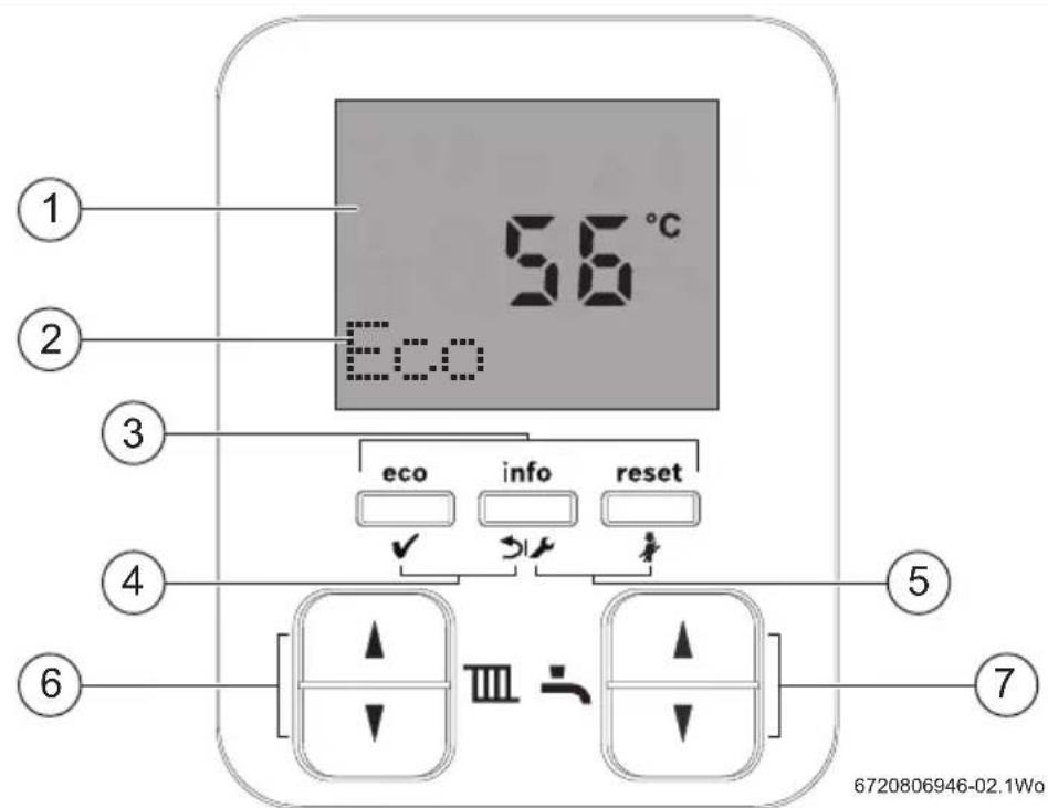
56°C Eco eco info reset ✓ ✓ ✓ ① ② ③ ④ ⑤ ⑥ ⑦ III ÷ 6720806946-02.1WoFig. 2 Display (example in standby with Eco mode active) and buttons
[1] Display Screen
[2] Eco mode active display message
[3] User function buttons:
• E c o b eco u t t o n ( )
- Manually select Economy or Pre-Heat mode
- Info button ( )

- Access to Info menu Function
- Reset button ( )

- Appliance reset button
[4] Menu functions buttons:
• O K b u t t o n ( )
- Confirms a sel
- Back button ( )
- To return to the previous option or menu
[5] Engineer function buttons:
- Spanner button ( )

- Service menu function button only
- Chimney sweep button ( )

- Engineer service and set up function only
[6] Central heating flow temperature adjustment buttons:
- Increase button ( )

- Increase value
- Decre
a▼s e button ( )
- Decrease value
[7] Cylinder hot water maximum temperature adjustment buttons, this function is only available if the optional integral diveter valve kit is fitted. (These buttons are also used in menu /scroll/adjustment, indicated by arrows on right of text display line):
- Increase button ( )

n - l n c r e a s e v a l u e
- Decre
a s e b u t t o n ( )
- Decrease value
3.1.1 Appliance display
| SCREEN DISPLAY | DESCRIPTION |
All possible screen symbols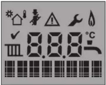 6720806944-32.1Wo 6720806944-32.1Wo | This screen is displayed briefly during appliance start up and shows all the symbols that could be displayed. |
Alpha/Numerical display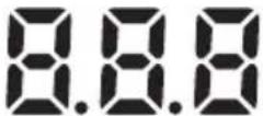 | Displays a temperature or appliance status code. |
Text display | Displays status, diagnostic code and short description information. |
Right hand arrows (text display) | Use domestic hot water arrow buttons to alter the menu item. |
| Flashing T (text display)[3CSH] | Appliance in component test mode. |
| Flashing A (text display)[A550] | Appliance in air purge mode. |
| Hot water[SAYC] | Displays this symbol during cylinder hot water demand, when controlled with Worcester intelligent controls in conjunction with the optional integral diverter valve kit. |
Central Heating | Displays this symbol during a central heating use. |
| Chimney sweep mode[2AAW] | Displays during service when the appliance is set to maximum or minimum output. |
| Alert[28ZG] | Displays with the appliance status code and diagnostic code during a fault condition. |
Service mode | Displays when a qualified service engineer is in the service menus. |
| Burner on(WMT) | The appliance is in operation and the flame is alight. |
| Centigrade(WBKZ) | Displays next to the temperature reading. |
| Confirmation[OWCK] | This symbol confirms a setting change. |
Table 3 Symbol description
Table 3 Symbol description
Info menu and operational status codes
These are not faults, but provide information concerning the current status of the appliance.
During normal appliance operation various Status codes can be displayed by pressing the info button.
The first screen of the Information menu displays the current Status code, this will change as the appliance runs through the various modes and sequences.
| Info menu No. Description | |
| i1 Current status• Appliance current operating status (see table 5 for operational status codes). | |
| i2 Previous status• Appliance previous operating status (see table 5 for operational status codes). | |
| i4 Maximum cylinder output (kW)• Maximum cylinder output (kW) set on the appliance. | |
| i8 Ionization current• Measured ionisation current (μA). | |
| i9 Flow temperature• Measured primary flow temperature of the appliance (°C). | |
| i11 Domestic hot water outlet temperature• Measured DHW flow temperature of the appliance (°C). | |
| i12 Cylinder set temperature• Displays the current set temperature for the cylinder (only available when using the optional integral diverter valve kit). | |
| i13 Cylinder temperature• Measured cylinder sensor temperature (°C) (only available when using the optional integral diverter valve kit). | |
| i15 Outdoor sensor• Temperature reading from outdoor temperature sensor, (only available if an outdoor sensor accessory is fitted) | |
| i20 CU version• Software version of the control box | |
| i21 HMI version• Software version of the HIS (Human Interface Software). | |
| i22 HCM version• Identification number of the HCM (Heating Control Module) and release version. |
Table 4 Info menu
These are not faults, but provide information concerning the current status of the appliance.
During normal appliance operation various Status codes can be displayed by pressing the info button.
The first screen of the Information menu displays the current Status code, this will change as the appliance runs through the various modes and sequences.
| Status code Description | |
| 200 Central heating system is being heated. | |
| 201 | Domestic hot water system is being heated (only available when using the optional integral diverter valve kit). |
| 202 Anti rapid cycle mode.The boiler has commenced anti-cycle period for central heating. Can be adjusted in boiler settings (2.3b).Default 5 Minutes | |
| 203 System stand by | |
| 204 System waiting, appliance waiting for heating system to cool. | |
| 208 Appliance in service Test mode (Min/Max) | |
| 265 EMS intelligent controller has forced stan-by-mode due to low heating load.The appliance is compensating for the power required from the EMS room controller is less than the minimum output of the boiler (only available when using EMS intelligent controls with the optional integral diverter valve kit). | |
| 268 Component test mode.Appliance is running the manual component test as activated in the menus. | |
| 270 Power up mode.(appliance is powering up). | |
| 283 Burner starting.The boiler prepares for a burner start. The fan and the pump are being controlled. | |
| 284 Gas valve(s) opened, flame must be detected within safety time.The boiler prepares for a burner start. The gas valve is being controlled. | |
| 305 | Anti fast cycle mode (domestic hot water keep warm function).Diverter valve is held in hot water position for a period of time (determined by the software) after hot water demand (only available when using the optional integral diverter valve kit). |
| 357 Appliance in air purge mode.Primary heat exchanger air venting program active - approximately 100 seconds. | |
| 358 Three way valve kick.If the 3-way valve hasn't moved in within 48 hours, the valve will operate once to prevent seizure (only available when using the optional integral diverter valve kit). | |
Table 5 Operational status codes
3.1.2 Basic adjust mode

If you see basic adjust mode in the home screen when attempting to make temperature adjustments, the appliance has been optimised for your heating system and should not need adjustment.
Please use your room thermostat to adjust your heating temperature if you still cannot achieve the desired room temperature the Installation, Commissioning and Servicing Instructions contain details on how to disable the basic adjust mode; this will allow further adjustment of the appliances settings.
3.2 Central heating
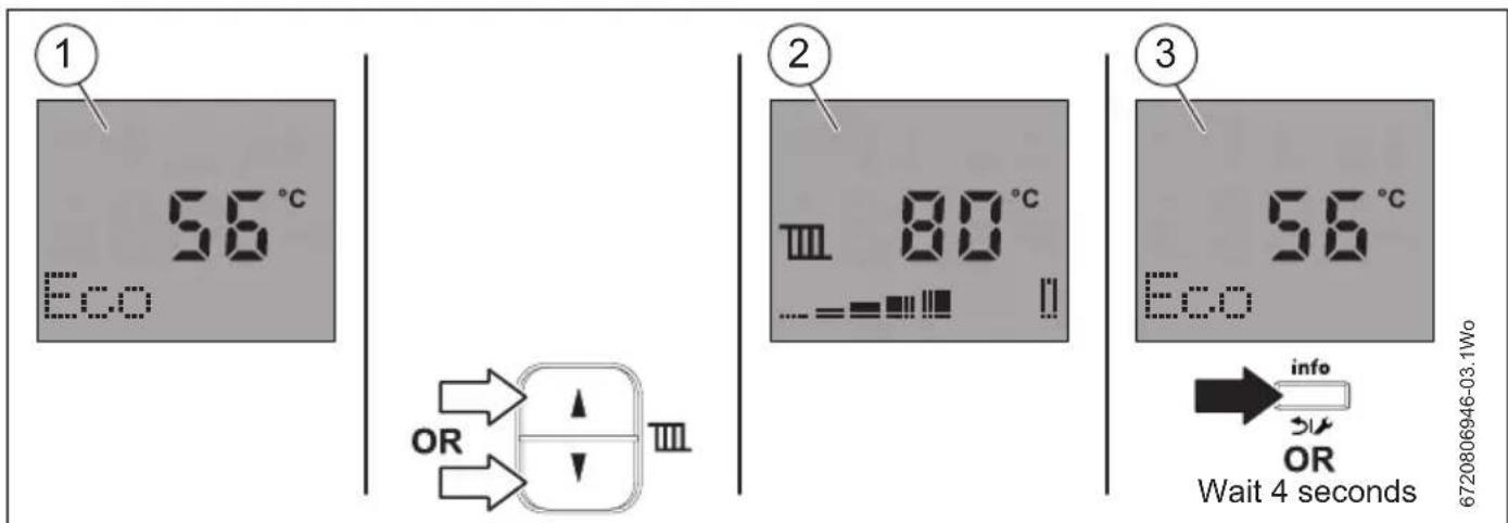
3.2.1 View appliance flow set temperature
The home screen will show the current appliance temperature [1].
▶ Briefly press either central heating adjustment buttons.
The display will change to the set temperature for the central heating [2].
▶ Press the OK button to confirm that the set temperature has been viewed, the display will also return to home screen [3].
-or-
▶ Wait 4 seconds and the display will return to the home screen [3].
text_image
① 56°C Eco OR ② 80°C Eco ③ 56°C Eco info OR Wait 4 seconds 6720806946-03.1WoFig. 3 Viewing appliance set temperature
3.2.2 Setting the appliance flow temperature for the system
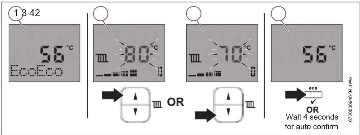
The home screen will show the current appliance temperature [1].
▶ Press the central heating increase or decrease adjustment buttons to select the desired flow temperature. The temperature displayed increases [2] / decreases [3] according to the adjustment made.
By holding the increase/decrease button the temperature displayed begins to change by larger increments.
▶ Press the OK button to confirm the value selected, the display will also return to the home screen [4].
-or-
▶ Wait 4 seconds for auto confirm and the display will return to the home screen [4].
text_image
1 3 42 56 °C EcoEco III 80 °C III 70 °C III 56 °C OR OR Wait 4 seconds for auto confirm 6720806946-04.1WoFig. 4 Adjust appliance flow temperature
3.2.3 Set economic temperature - Central heating
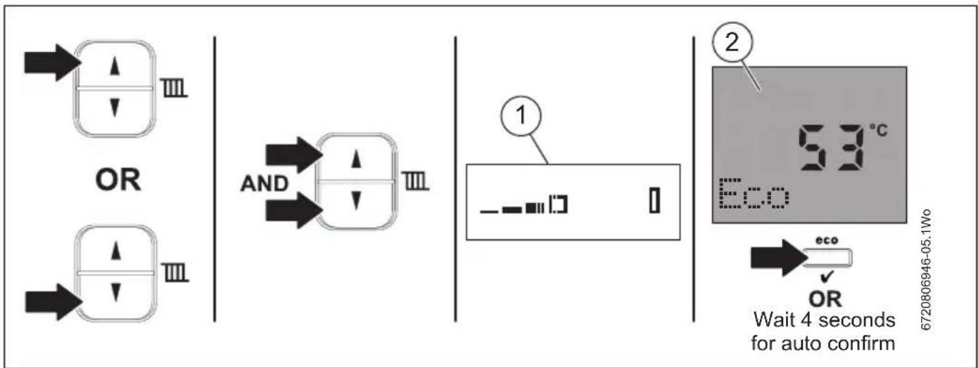
This setting ensures that the appliance will operate efficiently and is suitable for most heating system.
The home screen will show the current appliance temperature [1].
▶ Press both the central heating adjustment buttons.
The display will change to the economic value for the central heating [2].
▶ Press the OK button to confirm the value selection, the display will also return to the home screen [3].
-or-
▶ Wait 4 seconds for auto confirm and the display will return to the home screen [3].
text_image
OR AND ① - ② 53°C Eco Eco OR Wait 4 seconds for auto confirm 6720806946-05.1WoFig. 5 Central heating economic temperature
3.2.4 Turning the central heating off during the summer

Do not switch the appliance off at the mains fused spur.
▶ To turn your central heating off during warm periods:
▶ Set the programmer to OFF
-or-
▶ Turn the room thermostat temperature down to minimum.
3.2.5 Appliance frost protection
If you are leaving your property unoccupied during cold weather, please leave your programmer on constant and your room thermostat set to 15°C.
If the temperature within the appliance falls below 8^ C the pump will run to circulate water and prevent the system freezing.
- If the temperature does not rise to 9^ C within 30 minutes of the pump operating, the appliance will fire up.
If the temperature within the appliance falls below 5^ C the appliance will fire immediately, bringing the appliance temperature up to 12^ C to avoid the possibility of the appliance freezing.
This process will be repeated until such time that the appliance temperature does not drop below 8°C.
3.3 No integral diverter valve fitted: Cylinder temperature adjustment
If the domestic hot water adjustment buttons or "eco" button is pressed:
• N/A is displayed briefly
- This function will not affect the cylinder hot water temperature.
To adjust the water temperature of the cylinder:
▶ Adjust the cylinder temperature thermostat on the cylinder.
3.4 Optional integral diver valve kit fitted: Setting the cylinder hot water temperature

An external timer may be fitted instead of an internal timer.
3.4.1 View the cylinder hot water temperature set temperature

An internal or external timer/programmer coupled with the optional integral diverter valve kit with cylinder temperature sensor is required to be able to set the hot water temperature.
If an FR110, FW100 and Sense II controller is also fitted, in conjunction with the diverter valve, they assume control over the delivered temperatures, reducing the effect of the temperature controls. Set both to maximum.
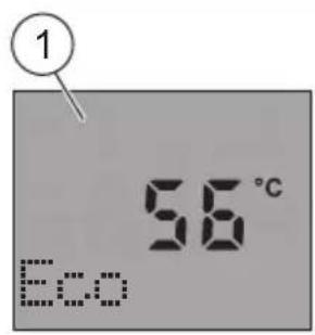
The home screen will show the current appliance temperature [1].
▶ Briefly press either hot water adjustment buttons.
The display will change to the set temperature for the hot water [2].
▶ Press the OK button to confirm the set temperature has been viewed, the display will also return to the home screen [3].
-or-
▶ Wait 4 seconds and the display will return to the home screen [3].
text_image
1 56°C Eco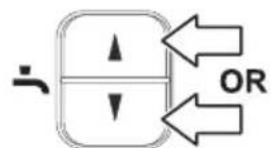
text_image
OR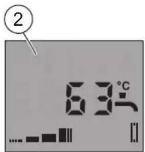
text_image
2 63°C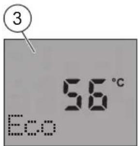
text_image
③ 56°C Eco
Wait 4 seconds
Fig. 6 Viewing hot water set temperature
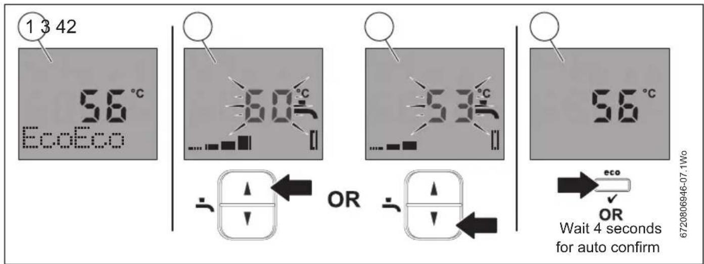
3.4.2 General cylinder hot water temperature adjustment
The home screen will show the current appliance temperature [1].
▶ Press the hot water increase or decrease adjustment buttons to select the desired hot water flow temperature.
The temperature displayed increases [2] /decreases [3] according to adjustment made.
By holding the desired increase/decrease button the temperature displayed begins to change by larger increments.
▶ Press the OK button to confirm the value selected, the display will also return to the main screen [4].
-or-
▶ Wait 4 seconds for auto confirm and the display will return to the main screen [4].
text_image
1 3 42 56°C EcoEco 60°C OR 53°C OR 56°C 6720806946-07.1Wo Wait 4 seconds for auto confirmFig. 7 Adjust hot water flow temperature
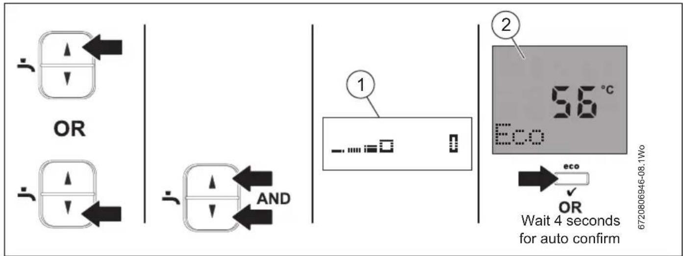
3.4.3 Mid point domestic hot water temperature
The mid point sets the maximum temperature for the cylinder to 50 °C.
The standard display will show the current requested cylinder temperature [1].
▶ Press both the hot water adjustment buttons.
The display will change to the mid point temperature for the cylinder [2].
▶ Press the OK button to confirm the value selected, the display will also return to main screen [3].
-or-
▶ Wait 4 seconds for auto confirm and the display will return main screen [3].
text_image
OR AND 1 2 56 °C Eco eco OR Wait 4 seconds for auto confirm 6720806946-08.1WoFig. 8 Hot water economic value
3.4.4 Domestic hot water eco and preheat modes
- Eco mode is an energy saving feature which disables the Preheat function:
- Eco is enabled by default, during the initial appliance start up and Eco is displayed.
- During the ON periods set by the time control, the appliance will heat the cylinder If the temperature is approximately 10°C below the set temperature.
- Preheat mode, the appliance heats the cylinder more frequently. This tops up the cylinder temperature for quicker heat up times, this is useful for large/longer demand periods during the hot water ON periods.
- During the ON periods set by the time control, the appliance will heat the cylinder if the temperature is approximately 5 °C below the set temperature.
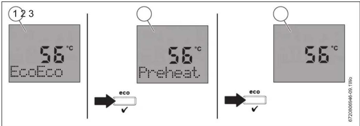
3.4.5 Domestic hot water preheat mode manual activation (Eco mode off)
Eco mode active [1]:
▶ Press the eco button (approximately 1 second) to enter the Preheat mode, when Preheat mode is active, "Preheat" will be displayed [2].
▶ To exit Preheat mode and return to Eco, press the eco button (approximately 1 second), Eco will be displayed [3].
text_image
1 2 3 56°C EcoEco 56°C Preheat 56°C eco eco 6720806946-09.1WoFig. 9 Manual activation of preheat/eco mode
3.4.6 Turn off the operation/fault diagnostic light (blue)
You may choose to deactivate the heat requirement demand light. Please ask your installer to set-up this feature.
The light will still flash to alert you to a possible fault, but will not activate during a heat requirement demand for heating or hot water.
4 S y s t e m p r e s s u r e
4.1 External filling link
This appliance is fitted to a sealed heating system which is pressurised. Your installer will advise you of the minimum and maximum pressure indicated on the pressure gauge.
▶ Check regularly that the pressure is maintained.
▶ If the pressure gauge reads less than 1 bar then the system requires re-charging.
▶ Contact your installer or maintenance engineer if a permanent significant decrease or increase in pressure is indicated on the pressure gauge.
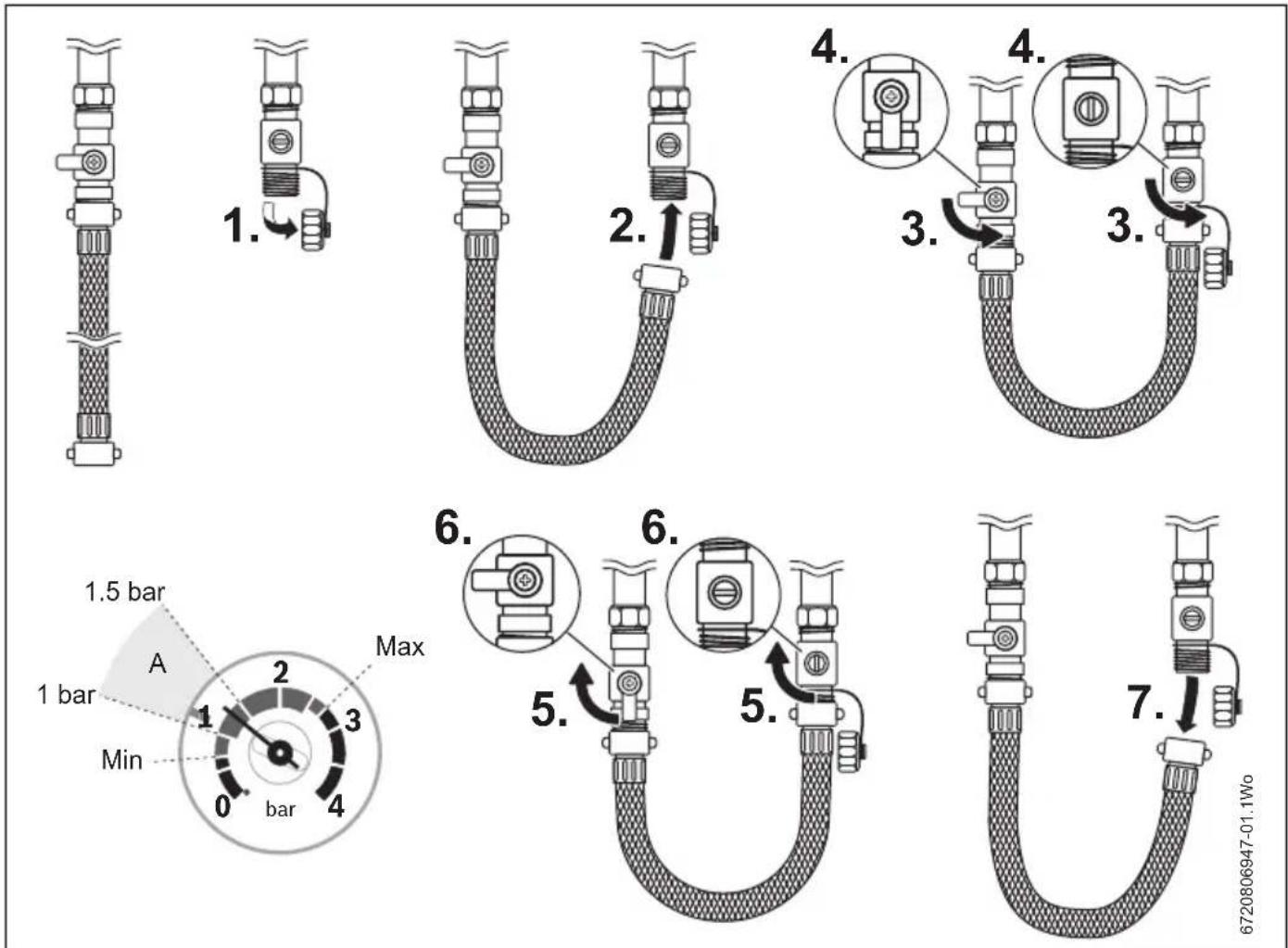
Once the external filling loop has been located, follow the instructions for re-pressurising the system.
- Unscrew blanking cap.
- Attach the hose to the valves, screw on hand-tight.
- Turn the handle/screwdriver slot through 90° to open the valves.
- The handle/screwdriver slot will be in-line with the valves
text_image
1.5 bar A 1 bar Min 0 bar 4 2.1 Max 6.1 5.1 6.1 5.1 7.1 6720806947-01.1WoFig. 10 External filling loop
- When the pressure reaches between the 1 and 1.5 bar marks (zone A), turn the handle/screwdriver slot back, through 90°, to close the valve.
- The handle/screwdriver slot will be at 90° to the valves
- Remove the hose and replace the blanking caps.
5 Clearances
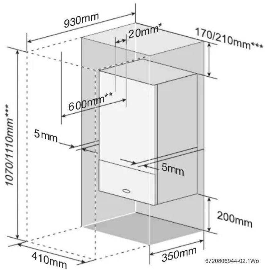
Your installer will have provided adequate space around the appliance for safety and servicing access.

CAUTION: Restricted space.
The appliance may overheat.
▶ Do not restrict this space with the addition of cupboards, shelves etc. next to the appliance.

NOTICE: Combustible and corrosive materials:
Chemically aggressive substances can corrode the appliance and invalidate any guarantee.
▶ Do not store or use any combustible materials (paper, thinners, paints, propellants, cleaning agents etc.) inside the cupboard containing the appliance or within the vicinity of the appliance.
text_image
930mm 20mm* 170/210mm*** 600mm** 5mm 5mm 200mm 410mm 350mm 1070/1110mm*** 6720806944-02.1WoFig. 11 Unventilated compartment
[*] Minimum clearances to removable door
[**] Minimum clearances required for servicing
[***] Height for either 60/100 flue or 80/125 flue
6 Maintaining your appliance
Your new gas-fired appliance represents a long term investment in a reliable, high quality product.
Wipe the appliance casing with a soft clean cloth. Please do not use chemical cleaning products which may damage the paint finish
In order to realise its maximum working life, and to ensure it continues to operate at peak efficiency and performance, it is essential that your appliance receives regular servicing and maintenance checks from a competent person beyond the initial guarantee period.
If your Greenstar gas-fired appliance should fail to operate correctly or requires servicing, please contact the Worcester, Bosch Group Appointments Team (see rear cover for details).
Details of the appliance including the Gas Council number can be found on the front cover of these User Instructions and on the appliance identification label on the appliance facia.
The Gas Council number is also listed on the front cover of your Installation, Commissioning and Servicing Instructions.
7 F a u l t f i n d i n g
In the event that the appliance stops functioning or does not perform as expected, you can carry out a few simple checks. These checks are some of the most common causes and are listed in the table below. Should the problem persist or if other fault codes are displayed, then it will be necessary to contact Worcester, Bosch Group.
This table gives information on basic operating system problems.
| Problem Cause Remedy | ||
| EA fault code flashing on display | No gas supply/low gas supply pressure | ► Contact your gas supplier. |
| Condensate outlet blocked | ► If it is safe to do so, check your condensate pipe outlet for blockages, such as ice or foreign objects. | |
| Flue blocked | ► If it is safe to do so, check your flue outlet for damage or blockages. | |
| Desired room temperature is not reached | Thermostatic radiator valve(s) set too low | ► Increase thermostatic radiator valve setting(s). |
| Temperature control for central heating flow on appliance is set too low | ► Increase central heating flow temperature control setting | |
| Low temperature setting on the room thermostat | ► Increase setting on the room thermostat. | |
| Air trapped in heating system | ► Bleed radiators and re-pressurise the heating system | |
| Low system water pressure | ► Re-pressurise the system, refer to page 18 | |
| Desired room temperature too high | Thermostatic radiator valves are set to high ► Turn down thermostatic radiator valves. | |
| Room thermostat is set too high | ► Turn down room ther | |
| Radiators are too hot | Temperature control on appliance set too high | ► Reduce central heating temperature by turning down the Central Heating control on appliance. Note: This could prevent your property reaching the desired temperature during cold weather periods. |
| Heating stays on for too long | Clock is incorrectly set ► Check clock setting and adjust | |
| No blue Operation/Fault Indicator | Momentary power failure | ► Disconnect appliance supply, wait a few seconds then reconnect. |
| Energy saving feature is activated | ► Ask your installer to reset the blue light | |
| Hot water temperature too low | Temperature set too low: · Cylinder thermostat control · Appliance hot water control (this feature is only available if the optional integral diverter valve has been fitted). | ► Check setting and adjust |
| Air trapped in heating system | ► Bleed radiators and re-pressurise the heating system | |
| Low system water pressure | ► Re-pressurise the system, refer to page 18 | |
| Hot water temperature too high | Temperature set too high: · Cylinder thermostat control · Appliance hot water control (this feature is only available if the optional integral diverter valve has been fitted). | ► Check setting and adjust |
Table 6 Fault finding
7.1 Appliance alert state
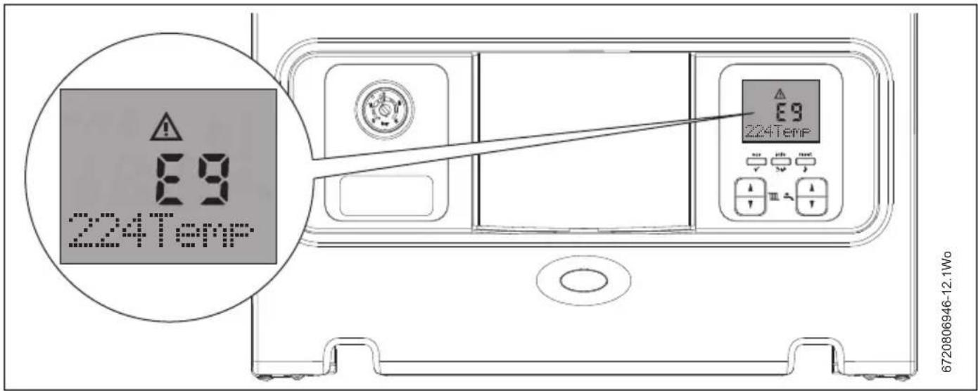
In the event of an alert, a fault code and an alert symbol will be displayed, and the blue operation/fault light will flash.
The information about the alert state will flash and scroll along the text display segment of the screen, giving more details of the alert state.
text_image
E9 224Temp E9 224Temp 6720806946-12.1WoFig. 12 Alert state example
7.2 Appliance reset
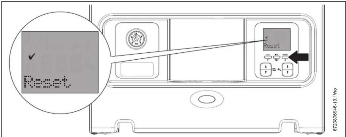
▶ To reset the appliance, press briefly once.
▶ "Reset" and are briefly displayed.
▶ If the reset was successful the appliance will return to normal operation.
If the reset was not successful then the alert code will be displayed again, and the blue operation/fault light will continue to flash.
text_image
Reset 6720806946-13.1WoFig. 13 Reset confirmation
Due to the internal safety systems of your Greenstar i appliance, some codes cannot be cleared by a simple reset. Please contact Worcester, Bosch Group for further assistance.
When calling Worcester, Bosch Group about a fault, it will be useful to quote the alert code and three digit number under the alert code, e.g. EA and 227. If there is a fault that cannot be reset by you, the user, then a service engineer visit will be necessary.
7.3 Extreme cold weather
The appliance has a large capacity siphonic condensate trap reducing the risk of condensate discharge freezing up in prolonged cold temperatures.
Like the CondenseSure siphon accessory, the expanded siphonic operation discharges every 15 to 20 minutes, resulting in:
- Increased velocity and flow rate.
- With only 3 to 4 siphonic actions per hour, the condensate pipework is empty for longer.
- Eliminated freezing potential.
- For a 48 hour period at -15^ provided the installation parameters are adhered to.
To maximise the effectiveness of this product the installer should:
- Keep the external pipework as short as possible.
- Ensure a fall of at least 2.5^ over horizontal sections.
- Minimise the number of bends and connectors.
- Remove burrs after cutting pipe.
- Remove surplus solvent from the interior of the pipe.
However in certain instances where the condensate pipe work is run externally or in an unheated area, such as a garage, the condensate pipe work can be at risk of freezing, even if well insulated.
A frozen/blocked condensate pipe will cause the appliance to shut down. For guidance on frozen condensate pipework please contact Worcester, Bosch Group also available on our website are helpful videos in the Customer service section.
8 Fault or breakdown
This appliance is supported in the UK and Eire by Worcester, Bosch Group.
Specialist service engineers are available to attend a breakdown occurring on this appliance.

Invoices for attendance and repair work carried out on this appliance by any third party will not be accepted.
- No charge will be made for parts and/or labour providing:
An appliance fault is found and the appliance is within the guarantee period. Reasonable evidence of this must be supplied on request. i.e. the Benchmark Checklist.
• A call-out charge will be made where: - The appliance is outside the guarantee period.
- Evidence cannot be provided that the first year service inspection has been carried out (i.e. an entry in the Benchmark Checklist).
- Our Field Service Engineer finds no fault with the appliance.
- The cause of breakdown is misuse or with other parts of your plumbing/heating system, or with equipment not supplied by Worcester, Bosch Group.
Technical support

No appliance fault is found on over 30% of all service calls.
In the case of a suspected fault, refer to the fault finding section of this guide.
In the event of a appliance fault or breakdown please contact Worcester, Bosch Group appointments team on 0330 123 9339. Your advisor will arrange for an engineer to call with the minimum of delay; under normal circumstances this will be from 1 - 3 working days (excluding weekends and bank holidays) for priority breakdown situations (no hot water and/or heating).
9 Tips on energy saving
Heating economically
The appliance provides a high level of comfort whilst keeping gas consumption low and so minimising the environmental impact.
The gas supply to the appliance's burner is regulated according to the demand for heat. The appliance operates with a low flame if the demand for heat reduces. The technical term for this process is modulating control.
Modulating control reduces temperature fluctuations and provides an even distribution of heat throughout the home. This means that the appliance may stay on for relatively long periods of time but will use less gas than a appliance that continually switches on and off.
Central heating systems with room thermostat/thermostatic radiator valves
With modern heating systems designed around a 20°C heat loss across the system, the optimum setting for a condensing appliance as described on page 14 set economic temperature. The system must be balanced correctly and the radiators may need upgrading.
The temperature of each room can be set individually (except primary room with the room thermostat) using the thermostatic radiator valves.
Room thermostats
Reducing the setting of the room thermostat by 1°C can reduce fuel consumption by up to 10%.
New control systems
Upgrade your heating control system if necessary with the latest equipment available.
Roof insulation
Around 30% of the heat loss from a property is through the roof. Replace any old insulation with new insulation, preferably of around 200mm thickness or more.
Window frames
Single glazed windows, particularly those with steel frames, can lose a great deal of heat. Consideration should be given to replacement with PVCu or wooden framed double glazed units.
Radiators
If a radiator is sited underneath a window, its performance will be affected if the curtains are allowed to drape over the radiator. Shelves fitted above or in front of the radiator should also be avoided.
It is advisable to manually adjust all thermostatic radiator valves every 2 - 3 months to prevent them sticking. Ensure radiator valves are correctly set and not damaged.
Draughts
Try to ensure that draughts around doors, windows, letter boxes and keyholes etc. are reduced by using a suitable draught excluder.

WARNING: Air vents
▶ Do not block or seal any air vents that are installed to ensure that the central heating appliance operates safely.
Curtains
Lined curtains, or heavier full length curtains can provide excellent insulation. However, always ensure that the curtains do not drape over radiators.
10 Environment/disposal
Environmental protection is a fundamental corporate strategy of the Bosch Group.
The quality of our products, their economy and environmental safety are all of equal importance to us and all environmental protection legislation and regulations are strictly observed.
We use the best possible technology and materials for protecting the environment taking account of economic considerations.
Packaging
We participate in the recycling programmes of the countries in which our products are sold to ensure optimum recycling.
All of our packaging materials are environmentally compatible and can be recycled.

USED APPLIANCES
▶ All Greenstar gas appliances are 100% recyclable.
The various assemblies can be easily dismantled and synthetic materials are marked accordingly. Assemblies can therefore be sorted by composition and passed on for recycling.
11 Your guarantee
This appliance has a guarantee against faulty materials or workmanship from the date of installation subject to the following terms and conditions:
- During the period of this guarantee any components of the appliance which are proven to be faulty or defective in manufacture will be exchanged or repaired free of charge by Bosch Thermotechnology Ltd.
- The householder may be asked to prove the date of installation, that the appliance was correctly commissioned and, where appropriate, the first year's service has been carried out to the satisfaction of Bosch Thermotechnology Ltd., when requested. These should be documented as a part of the Benchmark Checklist.
• The appliance has been used only for the normal domestic purposes for which it was designed.
This guarantee does not affect your statutory rights.
Guarantee registration
Your Greenstar appliance carries a guarantee against faulty material or manufacturer subject to Terms and Conditions.
To read the full Terms & Conditions please visit us on-line at www.worcester-bosch.co.uk/guarantee. The Guarantee Registration form is available on this same page and can be completed and submitted electronically.
Alternatively, please telephone one of our Guarantee Registration advisors on 0330 123 2552.
Your statutory rights are not affected by the manufacturers guarantee.
For your own record
Please ensure that the Benchmark Checklist has been completed by your installer or service engineer.
| Model | |
| Serial No. 1) | |
| Type/size | |
| Date of installation | |
| Name of Installer | |
| Telephone number of Installer |
Table 7
1) See appliance identification label on appliance facia (shown in figure 1, page 6) or Benchmark Checklist in the back of the Installation, Commissioning & Servicing Instructions.
12 Glossary
Central heating systems
All radiators must be heated at an even rate. If the top of a radiator is at a lower temperature than the bottom then it should be bled by releasing air through the bleed screw at the top of the radiator.
Ask your installer to show you how this is done.
This appliance is fitted to a sealed system. Should water leaks be found or if excessive bleeding is required, then a service engineer must be contacted to inspect the installation and rectify any fault.
Only additives that are compatible with aluminium may be used in the system. Any incompatible additive used will invalidate the guarantee.
Pluming and condensate drain
This is a condensing appliance and the flue terminal will, at times, give out a plume of water vapour. This is quite normal.
The appliance produces condensate which is discharged regularly by a syphon within the appliance via a plastic pipe to a drain. This pipe must not be blocked or altered in any way.
Room thermostat/programmer
A room thermostat / programmer must be fitted to control the central heating. This controls the times and temperatures of the central heating, preventing the appliance from firing unnecessarily. Refer to the instructions supplied with the thermostat and programmer for further information.
Thermostatic radiator valves
Thermostatic radiator valves must be fitted in sleeping accommodation. It is recommended that this type of valve is fitted to all but one of the radiators. The remaining radiator, where the room thermostat is located, must be uncontrolled and left open.
Pump over run function
After the appliance has finished a demand for central heating or hot water, the pump may continue to run for a short while to dissipate the heat from within the appliance.
Pump anti-seizure
If there has been no heating demand for 24 hours, the appliance will run the system pump for a few seconds to reduce the possibility of pump seizure during long periods of inactivity.
WORCESTER, BOSCH GROUP:
TECHNICAL SUPPORT: 0330 123 3366
APPOINTMENTS: 0330 123 9339
SPARES: 0330 123 9779
LITERATURE: 0330 123 9119
TRAINING: 0330 123 0166
SALES: 0330 123 9669
Worcester, Bosch Group
Cotswold Way, Warndon, Worcester WR4 9SW.
Tel. 0330 123 9559
Worcester, Bosch Group is a brand name of
Bosch Thermotechnology Ltd.
worcester-bosch.co.uk
6 720 806 947 (2015/03)

WORCESTER
Bosch Group