BD6900 - Sander Powertec - Free user manual and instructions
Find the device manual for free BD6900 Powertec in PDF.


| Product Type | Belt and Disc Sander |
| Brand | Powertec |
| Model | BD6900 |
| Horsepower (Peak) | 1.2 HP |
| Voltage | 120V |
| Amperage | 7.5 A |
| Frequency | 60 Hz |
| Phase | Single |
| Motor Speed | 3450 RPM |
| Belt Size | 6" x 48" |
| Belt Speed | 2400 FPM |
| Disc Diameter | 9" |
| Disc Speed | 3100 RPM |
| Table Dimensions | 7" x 10" |
| Table Tilt Range | 0° to 45° |
| Dust Port Diameter | 2" |
| Base Dimensions | 12" x 19" |
| Switch Type | Locking rocker switch with removable key |
| Power Cord | 3-conductor, 3-prong grounding plug (150V rated) |
| Warranty | 1 Year Limited |
| Dust Collection | Built-in dust port with included collection bag |
| Miter Gauge | Included |
| Sanding Belt Replacement | Yes, 6" x 48" |
| Sanding Disc Replacement | Yes, 9" adhesive disc |
Frequently Asked Questions - BD6900 Powertec
User questions about BD6900 Powertec
0 question about this device. Answer the ones you know or ask your own.
Ask a new question about this device
Download the instructions for your Sander in PDF format for free! Find your manual BD6900 - Powertec and take your electronic device back in hand. On this page are published all the documents necessary for the use of your device. BD6900 by Powertec.
USER MANUAL BD6900 Powertec
WITH BUILT-IN DUST COLLECTION


Visit us on the web at www.southerntechllc.com

You will need this manual for safety instructions, operating procedures, and warranty. Put it and the original sales invoice in a safe, dry place for future reference.
TABLE OF CONTENTS
SECTION PAGE

ETY RULES 1
Work Preparation
Work Area Preparation
Tool Maintenance
Tool Operation

SEMBLY 2
Unpackaging
Tool Needed
Mount Sander
Attach Abrasive Disc
Attach the Table Assembly to Use with Sanding Disc
Attach the Table Assembly to Use with Sanding Belt
Attach Dust Collection Bag
Power Source
Grounding Instructions
Extension Cords
Motor
Electrical Connections

ERATION 6
ON/OFF Switch
Adjust Belt Tracking Mechanism
Adjust Belt Assembly Position
Adjust Table Tilt Angle
Belt Sanding in Horizontal Position
Operate Sanding Belt
Operate Sanding Disc
Set Up the Miter Gauge
Replace Sanding Belt
Replace Sanding Disc Abrasive
MAINTENANCE 9
General Maintenance
Cleaning
Lubrication
Keep Tool in Repair

UBLESHOOTING 10

TS ILLUSTRATION & 11

RRANTY 14
PRODUCTION
SPECIFICATIONS
Horsepower (Peak HP).... 1.2
Voltage....120
Amp....7.5
Hertz....60
Phase....Single
RPM....3450
Belt size....6" x 48"
Belt speed....2400 FPM
Disc diameter....9"
Disc speed....3100 RPM
Table dimensions....7" x 10"
Table tilts....0° to 45°
Dust port diameter....2"
Base dimensions....12" x 19"
WARNING
For your own safety, read and understand all warnings and operating instructions before using any tool or equipment.
WARNING
Some dust created by operation of power tool contains chemicals known to the State of California to cause cancer, birth defects or other reproductive harm. To reduce your exposure to these chemicals: work in a well ventilated area and work with approved safety equipment. Always wear OSHA/NIOSH approved, properly fitting face mask or respirator when using such tools.
WARNING
Failure to follow these rules may result in serious personal injury. Remember that being careless for even a fraction of a second can result in severe personal injury.
WORK PREPARATION
- Wear proper apparel. Do not wear loose clothing, gloves, neckties, rings, bracelets or other jewelry which may get caught in moving parts of the tool.
- Nonslip protective footwear is recommended.
- Wear protective hair covering to contain long hair.
- Wear eye and hearing protection. Always use safety glasses. Eye protection equipment should comply with ANSI Z87.1 standards. Hearing equipment should comply with ANSI S3.19 standards.
- Wear face mask or dust mask if operation is dusty.
- Be alert and think clearly. Never operate power tools when tired, intoxicated or when taking medications that cause drowsiness.
WORK AREA PREPARATION
- Keep work area clean. Cluttered work areas and benches invite accidents.
• Work area should be properly lighted. - Do not use the machine in a dangerous environment. The use of power tools in damp or wet locations or in rain can cause shock or electrocution.
- Three-prong plug should be plugged directly into properly grounded, three-prong receptacle.
- Use the proper extension cord. Make sure your extension cord is in good condition and should have a grounding prong and the three wires of extension cord should be of the correct gauge.
- Keep children and visitors away. Your shop is a potentially dangerous environment. Children and visitors can be injured.
- Make your workshop childproof with padlocks, master switches or remove switch keys to prevent any unintentional use of power tools.
TOOL MAINTENANCE
- Turn the machine "OFF", and disconnect the machine from the power source prior to inspection.
- Maintain all tools and machines in peak condition. Keep tools sharp and clean for best and safest performance.
- Follow instructions for lubricating and changing accessories.
- Check for damaged parts. Check for alignment of moving parts, binding, breakage, mounting and any other condition that may affect tool's operation.
- Poorly maintained tools and machines can further damage the tool or machine and/or cause injury.
- A guard or any other part that is damaged should be repaired or replaced. Do not perform makeshift repairs.
TOOL OPERATION
- Avoid accidental start-up. Make sure that the tool is in the "OFF" position before plugging in.
- Use the right tool for your job. Do not force your tool or attachment to do a job for which it was not designed.
- Disconnect tool when changing parts.
- Don't force the workpiece on the machine. Damage to the machine and/or injury may result.
- Never leave tool running unattended. Turn the power off and do not leave tool until it comes to a complete stop.
- Do not overreach. Loss of balance can make you fall into a working machine, causing injury.
- Never stand on tool. Injury could occur if the tool tips, or if you accidentally contact the cutting tool.
- Know your tool. Learn the tool's operation, application and specific limitations before using it.
- Use recommended accessories. Use of improper accessories may cause damage to the machine or injury to the user.
- Handle workpiece correctly. Keep hands away from moving parts.
- Turn tool off if it jams.
- Always feed workpiece against the direction of the sanding rotation. To maintain control, properly support long or wide work-pieces.
CAUTION: Think safety! Safety is a combination of operator common sense and alertness at all times when tool is being used.
WARNING
Do not attempt to operate tool until it is completely assembled according to the instructions.
UNPACKING
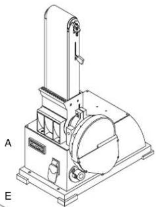
Refer to Figure 1.
Check for shipping damage. Check immediately whether all parts and accessories are included.
The sander comes assembled as one unit. Additional parts which need to be fastened to sander, should be located and accounted for before assembling.
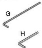
| ITEM | DESCRIPTION | QUANTITY |
| A | Sander | 1 |
| B | Dust Collection Bag | 1 |
| C | Bag Clamp | 1 |
| D | Mitre Gauge Assembly | 1 |
| E | Table Assembly | 1 |
| F | Disc | 1 |
| G | Wrench (4 mm) | 1 |
| H | Wrench (6 mm) | 1 |
Figure 1
natural_image
Technical line drawing of a mechanical device with labeled parts A and E (no text or symbols on the device itself)


natural_image
Simple line drawing of a cylindrical object with a protruding shaft (no text or symbols)
WARNING
Do not use the machine until it is completely assembled and you have read and understood the entire operating manuals.
TOOLS NEEDED
You will need the following tools to assemble and adjust the machine. (The tools are not included.)
- 10mm Wrench
• 5 and 6mm Hex Wrenches - Combination Square
• Phillips Screwdriver
MOUNT SANDER
- The machine must be installed in a well-lighted area with correct power supply.
- The machine can be installed on either a workbench or a tool stand by using bolts, lock washers, and hex nuts.
- The machine must be bolted to a firm and level surface.
- There must be enough clearance for the moving workpiece during operation. There must be enough room for safety operation of the machine.
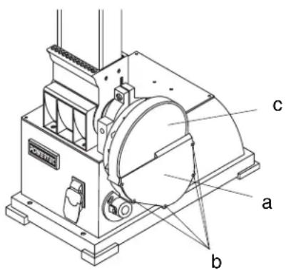
ATTACH ABRASIVE DISC
Refer to Figure 2
- Remove all screws (b) and remove the Disc Cover (a).
- Clean the surface of the aluminum disc.
- Peel off the protective paper on the back of the Abrasive Disc (c).
- With the adhesive side facing the aluminum disc, carefully place the Abrasive Disc (c) onto the center of aluminum disc.
- Confirm the position is satisfactory before press the Abrasive Disc (c) firmly and evenly against the aluminum disc in the entire area.
- Replace the Disc Cover (a) and tighten with screws (b).
Figure 2
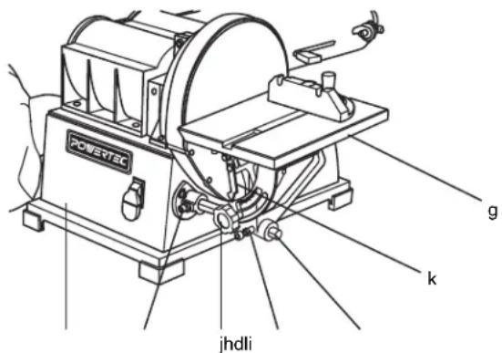
ATTACH THE TABLE ASSEMBLY TO USE WITH SANDING DISC
Refer to Figure 3
- Insert the Supporting Rod (d) into the mount on the side of base (i), to the left lower corner of the Sanding Disc.
-
Secure the Supporting Rod (d) onto the base (i) by tightening the Bolt (l) against the flat surface of the Supporting Rod (d). Check that Supporting Rod (d) is stable and will not roll.
-
Slide the Table Assembly (g) onto the Supporting Rod (d) and position the table platform in level position.
- Adjust the distance between the table platform and the Sanding Disc so it is 1/16" or less. Do not allow the Sanding Disc to touch any part of the Table Assembly (g).
- Secure the Table Assembly (g) in position with the Bolt (h). Tighten the Bolt (h) against the flat surface of the Supporting Rod (d). Check that Table Assembly (g) is stable.
- Set the table 90 degree (Perpendicular) to the Sanding Disc with a Combination Square. Secure the table in position by tightening the knob (j) on the tilt angle scale under the table platform.
• Zero the angle indicator: set the pointer (k) to 0 degree.
Figure 3
ATTACH THE TABLE ASSEMBLY TO USE WITH SANDING BELT
Refer to Figure 4
- With the Sanding Belt Assembly in upright position, locate the Mount (e) of side of Sanding Belt Assembly.
- Insert the Support Rod (d) into the Mount (e). Secure the Supporting Rod (d) onto the Mount (e) by tightening the Bolt (f) against the flat surface of the Supporting Rod (d). Check that Supporting Rod (d) is stable and will not roll.
- Slide the Table Assembly (g) onto the Supporting Rod (d) and position the table platform in level position.
- Adjust the distance between the table platform and the Sanding Belt so it is 1/16" or less. Do not allow the Sanding Belt to touch any part of the Table Assembly (g).
- Secure the Table Assembly (g) in position with the Bolt (h). Tighten the Bolt (h) against the flat surface of the Supporting Rod (d). Check that Table Assembly (g) is stable.
- Set the table 90 degree (Perpendicular) to the Sanding Belt with a Combination Square. Secure the table in position by tightening the knob (j) on the tilt angle scale under the table platform.
- Zero the angle indicator: by setting the pointer (k) to 0 degree.
Figure 4
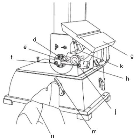
ATTACH THE DUST COLLECTION BAG
Refer to Figure 3
- Slide the Clamp (m) over the Sleeve of Dust Collection Bag (n).
- Locate the Dust Port on the side of the Base.
- Place the Dust Collection bag (n) and Clamp over the Dust Port. If necessary, adjust the size of the Clamp (m) opening by rotating the handle on the Clamp (m).
- Tighten the Clamp (m) by pressing the handle. Check that the Dust Collection Bag (n) is securely attached to the Dust Port.
POWER SOURCE
WARNING
Do not connect to the power source until the machine is completely assembled.
The machine is wired for 120 volts, 60 HZ alternating current. Before connecting the machine to the power source, make sure the switch is in the "OFF" position. Running the unit on voltages which are not within range may cause overheating and motor burn-out. Heavy loads require that voltage at motor terminals be no less than the voltage specified on nameplate.
- Power supply to the motor is controlled by a locking rocker switch. Remove the key to prevent unauthorized use.
GROUNDING INSTRUCTIONS
WARNING
Improper connection of equipment grounding conductor can result in the risk of electrical shock.
- The machine should be grounded while in use to protect operator from electrical shock.
- In the event of an electrical short circuit, grounding reduces the risk of electrical shock by providing an escape wire for the electric current.
-
This machine is equipped with an approved 3-conductor cord rated at 150V and a 3-prong grounding type plug for your protection against shock hazards.
-
Grounding plug should be plugged directly into a properly installed and grounded 3-prong grounding-type receptacle, as shown (Figure 5)
- The plug must be plugged into an outlet that is properly installed and grounded in accordance with all local codes and ordinances.
- Check with a qualified electrician or service personnel if these instructions are not completely understood or if in doubt as to whether the tool is properly grounded.
- Do not modify plug provided. If it will not fit in outlet, have proper outlet installed by a qualified electrician. Use only 3-wire extension cords, that have 3-prong grounding type plugs and matching 3-conductor receptacles that accept the machine's plug, as show in Figure 5

WARNING
Do not permit fingers to touch the terminals of plug when installing or removing from outlet.
- Inspect tool cords periodically, and if damaged, have repaired by an authorized service facility.
- The conductor with insulation having an outer surface that is green with or without yellow stripes is the equipment-grounding conductor. If repair or replacement of the electric cord or plug is necessary, do not connect the green (or green and yellow) wire to a live terminal.
A temporary 3-prong to 2-prong grounding adapter (see Figure 6) may be used to connect this plug to a matching 2-conductor receptacle as shown in figure 6. The temporary adapter should be used only until a properly grounded outlet can be installed by a qualified electrician.
Figure 6

In Canada, the use of temporary adapter is not permitted by the Canadian Electric Code. Where permitted, the rigid green tab or terminal on the side of the adapter must be securely connected to a permanent electrical ground such as a properly grounded water pipe, a properly grounded outlet box or a properly grounded wire system.
- Many cover plate screws, water pipes and outlet boxes are not properly grounded. To ensure proper ground, grounding means must be tested by a qualified electrician.
EXTENSION CORDS
Use proper extension cords. Make sure the extension cord is in good condition. Use only 3-wire extension cords have 3-prong grounding type plugs and 3-pole receptacles which accept the tool plug. When using an extension cord, make sure to use one heavy enough to carry the current of the machine. An undersized cord will cause a drop in the voltage, resulting in loss of power and overheating. Use the table to determine the minimum wire size (A.W.G.) extension cord.
Extension Cord Length
Wire Size..... A.W.G. Up to 25 ft..... 16 gauge
NOTE: Using extension cords over 25 ft. long is not recommended.
MOTOR
The sander is equipped with a 7,5 Amps motor. The 120 Volt motor has the following specifications: Horsepower (Peak HP)....1.2 Voltage....120 Amp....7.5 Hertz....60 Phase....Single RPM....3450
ELECTRICAL CONNECTIONS
WARNING
- Turn the switch off and disconnect the machine from power source before any repair or maintenance work.
- Some electrical wiring and connection work must be performed by qualified electrician in accordance with local regulations.
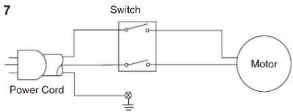
- Scheme of the motor and electric wiring inside this machine is shown in Figure 7.
- There is a green grounding wire fastened to the frame of the machine to provide Shock Protection. Do not disconnect the Grounding Wire from the frame.
• The Motor is rated for used at 120 Volts. - Connect this machine to 3-Conductor Power outlet with appropriate rating only.
- Use only 3-pronged Extension Power Cord with appropriate rating with this machine.
- When change the power cord, use only 3-pronged Power Cord with appropriate rating.
- The Power switch is a Single Pole Rocker switch with Locking Mechanism. Remove the Key when not in use to prevent accidents.
Figure 7
ON/OFF SWITCH
The ON/OFF switch is located in the front of Sander base. To turn the machine ON, pull the switch to the up position. To turn the machine OFF, push the switch to the down position.
NOTE: When the machine is not in use, the machine should be locked in the "OFF" position to prevent unauthorized use.
- To lock the machine, turn the switch to "OFF" position. Pull the key out. The switch cannot be turned on without the key.
- If the key is removed when the switch is at the "On: position, the switch can be turned off but cannot be turned on again.
- To unlock, place the key into the slot on switch unit until it snaps.
Figure 8

ADJUST BELT TRACKING MECHANISM

WARNING
Keep hands away from sanding belt, idler drum, drive drum, and any moving parts while conducting Belt Tracking Mechanism adjustment.
- To check sanding belt level, push the Tension Lever (b) toward drive drum to tighten the sanding belt.
- To check the belt tracking, switch the machine ON and OFF quickly. Watch the Sanding Belt (a) movement on the Idler and Drive Drum. The Sanding Belt should rotate without moving to the right and left.
- Use the Adjust Tracking Nut (c) to center the Sanding Belt (a). If the Sanding Belt (a) keeps moving to the right, turn the Adjust Tracking nut (c) to the left. If the Sanding Belt (a) keeps moving to the left, turn the Adjust Tracking nut (c) to the right.
- After each adjustment, switch the machine ON and OFF quickly and check the Sanding Belt (a) movement again. Repeat the procedures to adjust the belt tracking until the Sanding Belt (a) is centered.
Figure 9

ADJUST BELT ASSEMBLY POSITION
Refer to Figure 9
- The Sanding Belt Assembly (d) is designed to function at any angle between horizontal and vertical position. There are adjustable positive stops for both horizontal and vertical positions. The Horizontal Stop is located on top of the Base (h). It can secure the Sanding Belt Assembly in horizontal position.
- To change position, use L Wrench to loosen the Socket Head Bolt (g) in the Pivot Bracket (f). The Pivot Bracket is located between the Sanding Disc Assembly and The Sanding belt Assembly.
- Position the Sanding belt Assembly (d) to the desired angle and tighten the Socket Head Bolt (g) in the Pivot Bracket (f).
ADJUST TABLE TILT ANGLE
Refer to Figure 10
- The table platform can be adjusted from 0 to 45 degree (+/- 3°).
- To adjust the table tilt angle, loose the Knob (i) on the Tilt Angle Scale (k) under the Table Platform (j).
- Tilt the Table Platform (j) to the desired angel as indicated by the Scale (k). Tighten the Knob (i).
- Check that the distance between the Table Platform (j) and the sanding surface is 1/16" or less. Do not allow the sanding surface to touch any part of the Table Assembly. If adjustment is necessary, loose the Bolt (l) that attach the Table Assembly to the Supporting Rod and adjust the table platform position. Refer to ATTACH THE TABLE TO USE WITH SANDING BELT section for details.
Figure 10

BELT SANDING IN HORIZONTAL POSITION
Refer to Figure 11
- Remove Table Assembly and place the Sanding Belt Assembly (m) in horizontal position.
- The Idler Drum (p) can be safely used to sand concave surface.
- The Work Stop (n) and Dust Shroud (o) are integrated and are located at the Drive Drum (q) end of the Sanding Belt Assembly (q).
Figure 11

OPERATE SANDING BELT
• Always wear protective eye wear.
- Keep fingers away from abrasive surface and any moving parts.
- Use Table and Work Stop to securely position the workpiece during operation.
- Move workpiece across sanding belt evenly to minimize uneven wear of abrasive surface.
- Do not apply excessive force against the sanding belt. Allow sanding belt to sand away workpiece by applying gentle and consistent pressure.
- Use horizontal belt position with Work Stop to sand the sides of long workpiece.
- Use vertical belt position or Sanding Disc with Table to sand the ends of long workpiece.
- Use caution when sanding small or thin workpiece.
- Use flat portion of abrasive surface to sand convex object. Use Idler Drum portion of abrasive surface to sand concave object.
• For precise sanding, use Mitre Gauge.
- For beveled sanding, tilt the table to a desired angle.
- During sanding, position the workpiece securely against work stop or against table platform.
OPERATE SANDING DISC
• Always wear protective eye wear.
- Keep fingers away from abrasive surface and any moving parts.
- Use Table to securely position the workpiece during operation.
• Use Sanding Disc for small object only.
- Use sanding disc to sand flat or convex surface.
- Use only the "Down Side" of the disc surface. This is the area of the disc surface where the moving disc going downward. It is to the left of the operator.
- Move workpiece across sanding Disc "Down Side" evenly to minimize uneven wear of abrasive surface.
- The Sanding disc moves faster at outer edge and will remove working material faster.
• For precise sanding, use Mitre Gauge.
- For beveled sanding, tilt the table to a desired angle.
SET UP THE MITRE GAUGE
Refer to Figure 12
- Use Mitre Gauge (a) to securely hold the workpiece at a precise angle for sanding.
- Position the Mitre gauge (a) onto the groove on the table platform.
- Calibrate with a combination square (d) so the Mitre gauge (a) is perpendicular to the abrasive surface. Tighten the Knob (c). Set the pointer (b) to ZERO.
- Loose the Knob (c) and turn the Mitre Gauge (a) to desired angle. Tighten the Knob (c) to secure the Mitre Gauge (a) in place.
Figure 12

REPLACE SANDING BELT
Refer to Figure 13 and 14
- Replace Sanding Belt whenever it is worn, glazed, torn, or becomes uneven.
- Place the Sanding Belt Assembly in Vertical position.
- Remove the Table Assembly (e). Remove the Support Rod (f).
-
Remove Wing Screws with Washers (g), and Belt Dust Cover (h) at the base of Sanding Belt Assembly.
-
Release sanding belt tension by lift the Tension Lever (i) toward the Idler Drum (j).
- Remove the used Sanding Belt (k).
- Replace with a new Sanding Belt. If there is an arrow mark on the inside backing, the arrow should point in the direction of belt travel.
- Position and center the new Sanding Belt over the Drive Drum (o) and Idler Drum (j).
- Tighten the belt tension with the Tension Lever (i). Push the tension lever toward the Drive Drum(o).
- Replace the Dust Cover (h) and Wing Screws with Washers (g).
- Adjust the Bell Tracking Mechanism, Refer to ADJUST BELT TRACKING MECHANISM section.
- Replace Support Rod and Table Assembly.
Figure 13

Figure 14

REPLACE SANDING DISC ABRASIVE
Refer to Figure 14
- Remove Table Assembly. Remove Support Rod.
- Remove all screws (m) and remove the Disc Cover (l).
- Peel off the used Sanding Disc Abrasive.
- Clean the surface of the Aluminum Disc. Use Solvent to remove excessive residual adhesive if necessary.
- Peel off the protective paper on the back of the New Abrasive Disc (n).
- With the adhesive side facing the disc drum, carefully place the Abrasive Disc (n) onto the center of aluminum disc.
- Confirm the position is satisfactory before press the Abrasive Disc (n) firmly and evenly against the disc drum in the entire area.
- Replace the Disc Cover (I) and tighten with screws (m).
- Replace Support Rod and Table Assembly.
GENERAL MAINTENANCE
WARNING
- Turn switch to OFF position and disconnect the machine from power source.
- Wear safety goggles when blowing out sawdust to prevent eye injury.
CLEANING
- Keep machine and workplace clean. Avoid accumulation of sawdust on the tool.
- Be certain motor is kept clean and free of dust.
- Use soap and water to clean painted parts, rubber parts and plastic guards.
LUBRICATION
- A light coat of paste wax on the work table will make it easier to feed the workpiece and prevent rust.
KEEP TOOL IN REPAIR
- If power cord is worn, cut or damaged in any way, do not operate the machine.
- Replace any worn, damaged, or missing parts. Use parts listed to order parts.
- Any attempt to repair motor may create a hazard unless repair is done by a qualified service technician.
- Call the customer line at 1-877-393-7121.
| SYMPTOM POSSIBLE CAUSE(S) CORRECTIVE ACTION | ||
| Motor will not start 1. Low voltage2. Short circuit in line cord or plug3. Short circuit in motor4. Open circuit or loose connection in motor5. Incorrect fuses or circuit breakers6. Defective switch7. Defective capacitor | 1. Check power supply for proper voltage2. Inspect line cord and plug for faulty insulation or shorted connection3. Inspect connection on motor.4. Inspect connection on motor5. Replace with correct fuses or circuit breakers6. Replace switch7. Replace capacitor | |
| Motor stalls or fails to reach full speed | 1. Power overload2. Low voltage from power supply3. Undersized line cord4. Motor overload5. Short circuit or loose connection in motor6. Incorrect fuses or circuit breakers | 1. Reduce workload on the power supply2. Check power supply for proper voltage3. Use line cord of adequate size or reduce length of wiring4. Reduce load on motor5. Inspect the connection in motor for loose or shorted connection6. Replace with correct fuses or circuit |
| Motor overheats Motor | overloaded Reduce load on motor. Turn off the machine until motor cools down | |
| Machine slows down while operating | Applying too much pressure during operation | Ease up on pressure |
| Sandpaper not removing wood | Sandpaper glazed or loaded with sawdust | Replace sandpaper |
| Wood burns while sanding | Sandpaper glazed or loaded with sawdust | Replace sandpaper |
| Abrasive belt runs off top wheel | Not tracking properly Refer to “Adjust belt tracking” in operation section | |
| Dust Collection not working | 1. Dust bag full2. Belt loose or broken3. Impeller loose or broken | 1. Empty dust bag2. Replace belt3. Replace impeller |

6"x 9" BELT/DISC SANDER PARTS LIST
| Key No. | Part No. | Description | Specification | Qty | Key No. | Part No. | Description | Specification | Qty |
| 1 | BD6900001 | Idler Drum 1 | 60 | BD6900060 | Dust Chute | 1 | |||
| 2 | BD6900002 | Bearing 6201-2Z 2 | 61 | BD6900061 | Socket Head Screw | M8x10 | 2 | ||
| 3 | BD6900003 | Lock Nut 6 2 | 62 | BD6900062 | Driver Pulley | 1 | |||
| 4 | BD6900004 | Rubber Sleeve 2 | 63 | BD6900063 | Sponge | 1 | |||
| 5 | BD6900005 | Compression Spring 1 | 64 | BD6900064 | Disc Guard | 1 | |||
| 6 | BD6900006 | Retaining Ring 12 2 | 65 | BD6900065 | Disc Guard Pulg | 1 | |||
| 7 | BD6900007 | Set Screw 5x6 2 | 66 | BD6900066 | Socket Head Screw | M5x35 | 2 | ||
| 8 | BD6900008 | Nut 2 | 67 | BD6900067 | Fan | 1 | |||
| 9 | BD6900009 | Tracking Bolt 1 | 68 | BD6900068 | Flate Washer | 4 | |||
| 10 | BD6900010 | Tracking Nut | 1 | 69 | BD6900069 | Socket Head Screw | M5x10 | 4 | |
| 11 | BD6900011 | Idler Shaft 1 | 70 | BD6900070 | Flat Washer | 2 | |||
| 12 | BD6900012 | Idler Bracket | 1 | 71 | BD6900071 | Socket Head Screw 5 | 5 | ||
| 13 | BD6900013 | Guard | 2 | 72 | BD6900072 | Dust Chute | 1 | ||
| 14 | BD6900014 | Pan Head Screw | ST4x10L | 2 | 73 | BD6900073 | Self-Tapping Screw | ST4.8x13L | 8 |
| 15 | BD6900015 | Fiber Hex Nut 6 | 1 | 74 | BD6900074 | Set Screw | 8x8L | 2 | |
| 16 | BD6900016 | Compression Spring 1 | 75 | BD6900075 | Aluminum Disc | 1 | |||
| 17 | BD6900017 | Platen | 1 | 76 | BD6900076 | Abrasive Disc | 1 | ||
| 18 | BD6900018 | Hex Head Bolt | 6x25L 1 | 77 | BD6900077 | Disc Cover | 1 | ||
| 19 | BD6900019 | Tension Lever | 1 | 78 | BD6900078 | Pan Head Screw | 5x12 | 5 | |
| 20 | BD6900020 | Cover | 1 | 79 | BD6900079 | Table | 1 | ||
| 21 | BD6900021 | Flat Washer 5 | 2 | 80 | BD6900080 | Left Pivot Joint | 1 | ||
| 22 | BD6900022 | Pan Head Screw | M5x10 | 2 | 81 | BD6900081 | Flat Washer | 2 | |
| 23 | BD6900023 | Hex Head Screw | M6x16 | 6 | 82 | BD6900082 | Socket Head Screw | 5x10L 2 | |
| 24 | BD6900024 | Spring Washer 4 | 83 | BD6900083 | Table Bracket | 1 | |||
| 25 | BD6900025 | Hex Head Screw | M8x20 | 2 | 84 | BD6900084 | Socket Head Screw | 8x20L 1 | |
| 26 | BD6900026 | Mount | 1 | 85 | BD6900085 | Flat Washer 8 | 2 | ||
| 27 | BD6900027 | Bearing Plate | 1 | 86 | BD6900086 | Socket Head Screw | 8x10L 2 | ||
| 28 | BD6900028 | Bearing 6001-2RZ | 1 | 87 | BD6900087 | Knob | 1 | ||
| 29 | BD6900029 | Set Screw 8x10L | 4 | 88 | BD6900088 | Flat Washer | 1 | ||
| 30 | BD6900030 | Drive Drum 1 | 89 | BD6900089 | Socket Head Screw 5x10L 1 | ||||
| 31 | BD6900031 | Drive Shaft | 1 | 90 | BD6900090 | Pointer | 1 | ||
| 32 | BD6900032 | Wing Screw | 2 | 91 | BD6900091 | Flat Washer | 1 | ||
| 33 | BD6900033 | Flat Washer 5 | 2 | 92 | BD6900092 | Angle Scale | 1 | ||
| 34 | BD6900034 | Dust Cover | 1 | 93 | BD6900093 | Table Support Rod | 1 | ||
| 35 | BD6900035 | Support Seat 1 | 94 | BD6900094 | Right Pivot Joint | 1 | |||
| 36 | BD6900036 | Dust Housing | 1 | 95 | BD6900095 | Socket Head Screw | 5x6L | 8 | |
| 37 | BD6900037 | Sponge | 1 | 96 | BD6900096 | Flat Washer | 8 | ||
| 38 | BD6900038 | Pan Head Screw | 6x16 | 2 | 97 | BD6900097 | Base | 1 | |
| 39 | BD6900039 | Flat Washer 6 | 2 | 98 | BD6900098 | Right Foot | 2 | ||
| 40 | BD6900040 | Dust Deflector | 1 | 99 | BD6900099 | Left Foot | 2 | ||
| 41 | BD6900041 | Bearing 6004-2RZ | 1 | 100 | BD6900100 | Flat Washer | 2 | ||
| 42 | BD6900042 | Pivot | 1 | 101 | BD6900101 | Socket Head Screw | 6x16 | 2 | |
| 43 | BD6900043 | Hex Head Bolt | 6x20L 1 | 102 | BD6900102 | Mount | 1 | ||
| 44 | BD6900044 | Hex Nut 6 | 2 | 103 | BD6900103 | Pan Head Screw | 5x10L 4 | ||
| 45 | BD6900045 | Socket Head Screw | 6x30L 4 | 104 | BD6900104 | Cover | 1 | ||
| 46 | BD6900046 | Steel Ball 8 | 1 | 105 | BD6900105 | Switch Box | 1 | ||
| 47 | BD6900047 | Compression Spring | 1 | 106 | BD6900106 | Switch Plate | 1 | ||
| 48 | BD6900048 | Set Screw | 10x8 | 1 | 107 | BD6900107 | Switch | 1 | |
| 49 | BD6900049 | Socket Head Screw 8x25L | 1 | 108 | BD6900108 | Line Cord Hook | 2 | ||
| 50 | BD6900050 | Support Plate | 1 | 109 | BD6900109 | Pan Head Screw | 5x10L 4 | ||
| 51 | BD6900051 | Bracket | 1 | 110 | BD6900110 | Strain Relief | 1 | ||
| 52 | BD6900052 | Flat Washer 8 | 2 | 111 | BD6900111 | Pan Head Screw | 5x6L | 1 | |
| 53 | BD6900053 | Spring Washer 8 3 | 112 | BD6900112 | Serrated Washer 5 | 1 | |||
| 54 | BD6900054 | Socket Head Screw | 8x15 | 3 | 113 | BD6900113 | Line Cord | 1 | |
| 55 | BD6900055 | Hex Head Bolt | 8x35 | 2 | 114 | BD6900114 | Dust Port 1 | ||
| 56 | BD6900056 | Hex Nut 8 | 5 | 115 | BD6900115 | Bag Clamp | 1 | ||
| 57 | BD6900057 | Sponge | 1 | 116 | BD6900116 | Pin | 1 | ||
| 58 | BD6900058 | Flat Washer | 4 | 117 | BD6900117 | Clamp Handle | 1 | ||
| 59 | BD6900058 | Pan Head Screw | 6x8 4 | 118 | BD6900118 | Pivot Bolt | 6x40 | 1 | |
| 119 | BD6900119 | Dust Bag 1 | 130 | BD6900130 | Pan Head Screw 4x6L 1 | ||||
| 120 | BD6900120 | Flat Washer 2 | 131 | BD6900131 | Flat Washer 4 | 1 | |||
| 121 | BD6900121 | Pan Head Screw 2 | 132 | BD6900132 | Flat Washer 6 | 1 | |||
| 122 | BD6900122 | Guard 1 | 133 | BD6900133 | Pointer | 1 | |||
| 123 | BD6900123 | Pin 1 | 134 | BD6900134 | Miter Gauge | 1 | |||
| 124 | BD6900124 | Pin 1 | 135 | BD6900135 | Shaft 1 | ||||
| 125 | BD6900125 | Set Screw 2 | 136 | BD6900136 | V-Belt | 1 | |||
| 126 | BD6900126 | Motor 1 | 137 | BD6900137 | Wrench 4 1 | ||||
| 127 | BD6900127 | Set Screw 2 | 138 | BD6900138 | Wrench 6 | 1 | |||
| 128 | BD6900128 | Motor Pulley 1 | 139 | BD6900139 | Abrasive Belt | 1 | |||
| 129 | BD6900129 | Knob 1 |

Thank you for investing in a POWERTEC power tool. These products have been designed and manufactured to meet high quality standards and are guaranteed for domestic use against defects in workmanship or material for a period of 12 months from the date of purchase. This guarantee does not affect your statutory rights.
SOUTHERN TECHNOLOGIES LLC. BENCH TOP AND STATIONARY POWER TOOL LIMITED 1 YEAR WARRANTY AND 30-DAY SATISFACTION GUARANTEE POLICY
POWERTEC products are designed and manufactured by Southern Technologies LLC. All warranty communications should be directed to Southern Technologies LLC. 206 Terrace Dr. Mundelein, IL 60060, Attn: POWERTEC technical service; or by calling 1-877-393-7121 (toll free), 9 AM to 5 PM, Mondy through Friday, US Central Time.
30- DAY SATISFACTION GUARANTEE POLICY
During the first 30 days after the date of purchase, if you are dissatisfied with the performance of this POWERTEC tool for any reason, you may return the tool to the retailer from which it was purchased for a full refund or exchange. You must present proof of purchase and return all original equipment packaged with the original product. The replacement tool will be covered by the limited warranty for the balance of the one year warranty period.
LIMITED ONE YEAR WARRANTY
This warranty covers all defects in workmanship or materials in this POWERTEC tool for a one year period from the date of purchase. This warranty is specific to this tool. Southern Technologies, LLC reserves the right to repair or replace the defective tool, at its discretion.
HOW TO OBTAIN SERVICE
To obtain service for this POWERTEC tool you must return it, freight prepaid, to an authorized POWERTEC service center for bench top and stationary power tools. You may obtain the location of the authorized service center nearest you by calling (toll free) 1-877-393-7121 or by logging on to the POWERTEC website at www.southerntechllc.com. When requesting warranty service, you must present the proof of purchase documentation, which includes a date of purchase. The authorized service center will either repair or replace any defective part, at our option at no charge to you. The repaired or replacement unit will be covered by the same limited warranty for the balance of one year warranty period.
WHAT IS NOT COVERED
This warranty applied to the original purchaser at retailer and may not be transferred.
This warranty does not cover consumable items such as saw blades, knives, belts, discs, cooling blocks and sleeves. This warranty does not cover required service and part replacement resulting from normal wear and tear, including accessory wear.
This warranty does not cover any malfunction, failure or defect resulting from:
1) misuse, abuse, neglect and mishandling not in accordance with the owner's manual.
2) damage due to accidents, natural disasters, power outage, or power overload.
3) commercial or rental use.
4) alteration, modification or repair by other than an authorized service center for POWERTEC product.
DISCLAIMER
To the extent permitted by applicable law, all implied warranties, including warranties of MERCHANTABILITY or FITNESS FOR A PARTICULAR PURPOSE, are disclaimed. Any implied warranties, that cannot be disclaimed under state law are limited to one year from the date of purchase. Southern Technologies LLC. is not responsible for direct, indirect, incidental or consequential damages. Some states do not allow limitations on how long an implied warranty lasts and/or do not allow the exclusion or limitation of incidental or consequential damages, so the above limitations may not apply to you. This warranty gives you specific legal rights, and you may also have other rights which vary from state to state. Southern Technologies LLC., makes no warranties, representations, or promises as to the quality or performance of its power tools other than those specifically stated in this warranty.

NOTE
POWERTEC PRO
Southern Technologies, LLC
206 Terrace Drive
Mundelein, Illinois 60060

- WITH BUILT-IN DUST COLLECTION
- TABLE OF CONTENTS
- ETY RULES 1
- SEMBLY 2
- ERATION 6
- MAINTENANCE 9
- UBLESHOOTING 10
- TS ILLUSTRATION & 11
- RRANTY 14
- PRODUCTION
- SPECIFICATIONS
- WARNING
- WORK PREPARATION
- WORK AREA PREPARATION
- TOOL MAINTENANCE
- TOOL OPERATION
- UNPACKING
- TOOLS NEEDED
- MOUNT SANDER
- ATTACH ABRASIVE DISC
- Refer to Figure 2
- ATTACH THE TABLE ASSEMBLY TO USE WITH SANDING DISC
- Refer to Figure 3
- ATTACH THE TABLE ASSEMBLY TO USE WITH SANDING BELT
- Refer to Figure 4
- ATTACH THE DUST COLLECTION BAG
- POWER SOURCE
- GROUNDING INSTRUCTIONS
- EXTENSION CORDS
- Extension Cord Length
- MOTOR
- ELECTRICAL CONNECTIONS
- ON/OFF SWITCH
- ADJUST BELT TRACKING MECHANISM
- ADJUST BELT ASSEMBLY POSITION
- Refer to Figure 9
- ADJUST TABLE TILT ANGLE
- Refer to Figure 10
- BELT SANDING IN HORIZONTAL POSITION
- Refer to Figure 11
- OPERATE SANDING BELT
- OPERATE SANDING DISC
- SET UP THE MITRE GAUGE
- Refer to Figure 12
- REPLACE SANDING BELT
- Refer to Figure 13 and 14
- REPLACE SANDING DISC ABRASIVE
- Refer to Figure 14
- GENERAL MAINTENANCE
- CLEANING
- LUBRICATION
- KEEP TOOL IN REPAIR
- SOUTHERN TECHNOLOGIES LLC. BENCH TOP AND STATIONARY POWER TOOL LIMITED 1 YEAR WARRANTY AND 30-DAY SATISFACTION GUARANTEE POLICY
- 30- DAY SATISFACTION GUARANTEE POLICY
- LIMITED ONE YEAR WARRANTY
- HOW TO OBTAIN SERVICE
- WHAT IS NOT COVERED
- DISCLAIMER
- NOTE
- POWERTEC PRO
Brand : Powertec
Model : BD6900
Category : Sander