
LE485SB - Grill Napoleon - Free user manual and instructions
Find the device manual for free LE485SB Napoleon in PDF.


| Product Type | Gas Grill |
| Model | LE485SB |
| Brand | Napoleon |
| Main Burners (3) | Stainless steel tube burners, total 14.4 kW |
| Rear Burner | Infrared ceramic, 4.0 kW |
| Side Burner | Standard side burner, 3.8 kW |
| Gas Types | Propane (30/37/50 mbar) or Butane (28-30/30/37/50 mbar) or Natural Gas (20 mbar) |
| Cooking Grids | Porcelain-enameled cast iron (or stainless steel upgrade) |
| Sear Plates | Stainless steel, 5-year warranty |
| Warming Rack | Yes, included |
| Rotisserie | Compatible (kit optional) |
| Ignition | Piezo igniter with cross-lighting |
| Lid Material | Stainless steel or porcelain enamel (model dependent) |
| Cart Material | Stainless steel and painted steel |
| Wheels | 2 revolving casters, 2 non-revolving casters |
| Dimensions (approx.) | 52" W x 24" D x 46" H (with lid closed) |
| Weight (approx.) | 135 lbs (61 kg) |
| Electrical (internal lights) | 230V~50Hz, 0.09A, 20W transformer (some models) |
| Warranty | President's Limited Lifetime on castings and lid; 10 years on burners; 5 years on sear plates and cast iron grids; 2 years on other parts |
| Storage | Outdoor only; propane cylinder stored outside enclosure |
| Safety Features | Internal regulator, leak test required, flame failure device, heat shields |
| Certification | CE, meets EU gas appliance directive |
Frequently Asked Questions - LE485SB Napoleon
User questions about LE485SB Napoleon
0 question about this device. Answer the ones you know or ask your own.
Ask a new question about this device
Download the instructions for your Grill in PDF format for free! Find your manual LE485SB - Napoleon and take your electronic device back in hand. On this page are published all the documents necessary for the use of your device. LE485SB by Napoleon.
USER MANUAL LE485SB Napoleon
This gas grill must be used only outdoors in a well-ventilated space and must not be used inside a building, garage, screened-in porch, gazebo or any other enclosed area.

natural_image
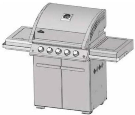
Illustration of a standard gray electric grill with control panel and side grilles (no text or symbols)
LE485SB, LE485RSB, LE485RSIB

DANGER
IF YOU SMELL GAS:
- Shut off gas to the appliance.
- Extinguish any open flame.
- Open lid.
- If odor continues, keep away from the appliance and immediately call your gas supplier or fire department.

WARNING
Do not try to light this appliance without reading the "LIGHTING" instructions section of this manual.
Do not store or use gasoline or other flammable liquids or vapors in the vicinity of this or any other appliance. An L.P. cylinder not connected for use must not be stored in the vicinity of this or any other appliance. If the information in these instructions is not followed exactly, a fire or explosion may result, causing property damage, personal injury or death.
Notice to Installer: Leave these instructions with the grill owner for future reference.
THANK YOU FOR CHOOSING NAPOLEON
NAPOLEON products are designed with superior components and materials, and are assembled by trained craftsmen who take great pride in their work. The burner and valve assembly are leak tested and test-fired at a quality test station. This grill has been thoroughly inspected by a qualified technician before packaging and shipping to ensure that you, the customer, receive the quality product you expect from NAPOLEON.
We at Napoleon are dedicated to you, "our valued customer." It is our goal to provide you with the necessary tools for an unforgettable grilling experience. This manual is provided to assist you in assuring your new grill is assembled, installed, maintained and cared for properly. It is important to read and understand this entire manual before operating your new grill to ensure you fully understand all the safety precautions and features your grill has to offer. By carefully following these instructions, you will enjoy years of trouble-free grilling. If this product fails to meet your expectations, for any reason, please call our customer solutions department at 1-866-820-8686 between 9 AM and 5 PM (Eastern Standard Time) or visit our Website at www.napoleongrills.com.
Napoleon Gas Grill President's Limited Lifetime Warranty

NAPOLEON warrants that components in your new NAPOLEON product will be free from defects in material and workmanship from the date of purchase, for the following period:
Aluminum castings / stainless steel base Lifetime
Stainless steel lid Lifetime
Porcelain enamel lid Lifetime
Stainless steel cooking grids Lifetime
Stainless steel tube burners 10 years
Stainless steel sear plates 5 years
Porcelain-enameled cast iron cooking grids 5 years
Stainless steel infrared rotisserie burner 5 years
Ceramic infrared rotisserie burner (excluding screen) 3 years
Ceramic infrared bottom or side burners (excluding screen) 2 years
All other parts 2 years
plus5 indicates a period of extended warranty coverage whereby the replacement part will be made available to the consumer for an additional 5 years at 50% of the current retail price.
Conditions and Limitations
NAPOLEON warrants its products against manufacturing defects to the original purchaser only, provided that the purchase was made through an authorized NAPOLEON dealer and is subject to the following conditions and limitations:
This factory warranty is non-transferable and may not be extended what-so-ever by any of our representatives. The gas grill must be installed by a licensed, authorized service technician or contractor. Installation must be done in accordance with the installation instructions included with the product and all local and national building and fire codes.
This limited warranty does not cover damages caused by misuse, lack of maintenance, grease fires, hostile environments, accident, alterations, abuse or neglect and parts installed from other manufacturers will nullify this warranty. Discoloration to plastic parts from chemical cleaners or UV exposure is not covered by this warranty. This limited warranty further does not cover any scratches, dents, painted finishes, corrosion or discoloring by heat, abrasive and chemical cleaners, nor chipping on porcelain enamel parts, nor any components used in the installation of the gas grill.
Should deterioration of parts occur to the degree of non-performance (rusted through or burnt through) within the duration of the warranted coverage, a replacement part will be provided.
After the first year, with respect to this President's Limited Lifetime Warranty NAPOLEON may, at its discretion, fully discharge all obligations with respect to this warranty by refunding to the original warranted purchaser the wholesale price of any warranted but defective part(s).
NAPOLEON will not be responsible for the installation, labor or any other costs or expenses related to the re-installation of a warranted part, and such expenses are not covered by this warranty.
Notwithstanding any provision contained in this President's Limited Lifetime Warranty NAPOLEON's responsibility under this warranty is defined as above and it shall not in any event extend to any incidental, consequential, or indirect damages.
This warranty defines the obligation and liability of NAPOLEON with respect to the NAPOLEON gas grill and any other warranties expressed or implied with respect to this product, its components or accessories are excluded.
NAPOLEON neither assumes, nor authorizes any third party to assume, on its behalf, any other liabilities with respect to the sale of this product.
NAPOLEON will not be responsible for: over firing, blow outs caused by environmental conditions such as strong winds, or inadequate ventilation,
Any damages to the gas grill due to weather damage, hail, rough handling, damaging chemicals or cleaners will not be the responsibility of NAPOLEON.
The bill of sale or copy will be required together with a serial number and a model number when making any warranty claims from NAPOLEON.
NAPOLEON reserves the right to have its representative inspect any product or part prior to honoring any warranty claim.
NAPOLEON shall not be liable for any transportation charges, labor costs, or export duties.

WARNING! Failure to follow these instructions could result in property damage, personal injury or death. Read and follow all warnings and instructions in this manual prior to operating grill.
Safe Operating Practices
- This gas grill must be assembled exactly according to the instructions in the manual. If the grill was stored assembled, you must review the assembly instructions to confirm correct assembly and perform the required leak tests before operating the grill.
- Read the entire instruction manual before operating the gas grill.
- Under no circumstance should this gas grill be modified.
- Follow lighting instructions carefully when operating grill.
- Gas must be turned off at the propane cylinder or at the natural gas supply valve when the gas grill is not in use.
- Keep children and pets away from hot grill, DO NOT allow children to climb inside cabinet.
- Children should be supervised to ensure that they do not play with the appliance.
- This appliance is not intended for use by persons (including children) with reduced physical, sensory or mental capabilities, or lack of experience and knowledge, unless they have been given supervision or instruction concerning use of the appliance by a person responsible for their safety.
- Do not leave the grill unattended while in use.
- Do not move grill when hot or operating.
• This grill is for household use only.
- This gas grill must not be installed in or on recreational vehicles and/or boats.
- This gas grill must only be stored outdoors in a well-ventilated area and must not be used inside a building, garage, screened -in porch or any other enclosed area.
- Maintain proper clearance to combustibles (16" (410mm) to rear of unit 7" (178mm) to sides). Additional clearance is recommended near vinyl siding or panes of glass.
- At all times keep the ventilation openings of the cylinder enclosure free and clear from debris.
- Do not operate unit under any combustible construction.
- Do not locate in windy settings. High winds adversely affect the cooking performance of the gas grill.
- When the gas grill is stored indoors, the propane cylinder must be disconnected from the grill and stored outdoors in a well-ventilated area, disconnected cylinders must not be stored in a building, garage or other enclosed area. Natural gas units must be disconnected from the supply when being stored indoors.
- Inspect the gas line hose before each use. If there is evidence of excessive abrasion or wear, it must be replaced before using the gas grill, with a replacement hose assembly specified by the grill manufacturer.
- Never store a spare LP gas cylinder under or near this grill.
- Never fill the cylinder beyond 80% full.
- When changing out the gas cylinder, ensure there are no nearby sources of ignition. Do not smoke.
- Leak test all connections before initial use, even if the grill was purchased fully assembled, annually or whenever any gas component has been replaced.
- Never use natural gas in a unit designed for liquid propane gas.
- Never use lighter fluid in a gas grill.
- Use charcoal briquettes only with a Napoleon charcoal tray designed for this unit.
- Burner controls must be off when turning supply cylinder on.
- Do not light burners with lid closed.
- Do not operate rear burner with main burners operating.
- The lid is to be closed during the preheat period.
- Do not route hose underneath drip pan-proper hose clearance to bottom of unit must be maintained.
- Clean grease tray and sear plates regularly to avoid build-up, which may lead to grease fires.
- Remove warming rack before lighting rear burner. The extreme heat will damage the warming rack.
- Ensure sear plates are positioned properly according to sear plate installation instructions.
- Do not use side shelves to store lighters, matches or any other combustibles.
- Keep gas line away from heated surfaces
- Keep any electrical supply cord away from water or heated surfaces.
- Inspect infrared burner venturi tube for spider webs and other obstructions periodically. Clean the tubes completely if you find any such obstructions.
- The outdoor cooking gas grill and its individual shutoff valve must be disconnected from the gas supply piping system during any pressure testing of that system at test pressures in excess of 0.5psi (3.5kPa).
- The outdoor cooking gas grill must be isolated from the gas supply piping system by closing its individual manual shutoff valve during any pressure testing of the gas supply piping system at test pressures equal to or less than 1/2 psi (3.5 kPa).

Electrical Precautions
WARNING! Failure to follow these instructions could result in property damage, personal injury or death.
- 230V - 50HZ -.09A -20W - type 2 transformer (Electrical Rating - Internal Light Models Only).
- To protect against electric shock, do not immerse cord or plugs in water or other liquid.
- Unplug from the outlet when not in use and before cleaning. Allow to cool before putting on or taking off parts.
- Do not operate any outdoor cooking gas appliance with a damaged cord, plug, or after the appliance malfunctions or has been damaged in any manner. Contact the manufacturer for repair.
- If the supply cord is damaged, it must be replaced by the manufacturer or its service agent or a similarly qualified person in order to avoid a hazard.
- Do not let the cord hang over the edge of a table or touch hot surfaces.
- Do not use an outdoor cooking gas appliance for purposes other than intended.
- When connecting, first connect plug to the outdoor cooking gas appliance then plug appliance into the outlet.
- Use only a Ground Fault Interrupter (GFI) protected circuit with this outdoor cooking gas appliance.
- Never remove the grounding plug or use with an adapter of 2 prongs.
- Use only extension cords with a 3 prong grounding plug, rated for the power of the equipment, and approved for outdoor use with a W-A marking.
Correct Disposal Of This Product
This marking indicates that this product should not be disposed with other household wastes throughout the EU. To prevent possible harm to the environment or human health from uncontrolled waste disposal, recycle it responsibly to promote the sustainable reuse of material resources. To return your used device, please use the return and collection systems or contact the retailer where the product was purchased.
They can take this product for environmental safe recycling.
Gas Cylinder
Use only gas cylinders, which meet national and regional codes. The minimum cylinder size for butane units is 13kg, and for propane units is 6kg. Ensure that the cylinder can provide enough fuel to operate the appliance. If in doubt, check with your local gas supplier.
- Use caution when handling the cylinder valve.
- Never connect a cylinder, which does not meet local codes.
All cylinders 7kg or larger must be placed outside the enclosure (under the right side shelf) on level ground. Cylinders smaller than 7kg (maximum size 465mm high by 306mm wide) may be placed inside the enclosure, on the right side of the bottom shelf. Only cylinders connected to the appliance may be stored in the enclosure, or close to the appliance. Spare cylinders must not be stored in the enclosure, or in close proximity of an operating unit. Cylinders must not be exposed to extreme heat or direct sunlight.

WARNING! Ensure that the hose is routed to maintain proper clearance to the underside of the unit. Hoses that contact high temperature surfaces may melt and leak, causing a fire.
Cylinder Connection: Ensure that the gas regulator hose is kink free. Remove the cap or plug from the cylinder fuel valve. Tighten regulator to cylinder valve. Leak test all joints prior to using the barbecue. A leak test must be performed annually, and each time a cylinder is hooked up, or if a part of the gas system is replaced.

WARNING!
- Do not route hose underneath drip pan.
- Do not route hose between space in bottom shelf and back panel.
- Do not route hose over top of back panel.
- Ensure all connections are tightened using two wrenches. Do not use Teflon tape or pipe dope on any hose connection.
- Ensure the hose does not contact any high temperature surfaces, or it may melt and leak causing a fire.
- Do not use enclosure to store excess hose, as there is a greater chance of the hose contacting a hot surface, it may melt and leak causing a fire.
Gas Hose
- If the hose and regulator are not included by the manufacturer, then only hoses and regulators which meet national and regional codes are to be used.
- Ensure that the hose does not come into contact with grease, other hot drippings, or any hot surfaces on the appliance.
- Check hose regularly. In the case of rips, melting or wear, replace hose before using the appliance.
- The recommended hose length is 0.5m. The hose must not be longer than 1.5m.
- Ensure that the hose is twist and kink free when installed.
- Replace the hose before expiry date printed on the hose.
Technical Data
The following table lists input values for the appliance.
| Burner | Orifice Size | (Gross) Heat Input (Total) | Gas Usage (Total) |
| I | II | I | II |
| Main | 1.18mm (56) | 1.65mm | 14.4 kW | 1042 g/hr | 1370 L/hr |
| Back | 1.04mm (59) | 1.51mm (53) | 4.0 kW | 290 g/hr | 380 L/hr |
| Side | 1.02mm (60) | 1.45 mm | 3.8 kW | 275 g/hr | 362 L/hr |
Certified Gases / Pressures - Check rating plate to ensure that it corresponds with following list.
| Gas Category | 1 3B/P(30) | 1 3+(28-30/37) | 1 3B/P(37) | 1 3B/P(50) | 1 2H(20) | 1 2E(20) |
| Orifice Sizes (see above) | I | I | I | I | II | II |
| Gases / Pres-sures | Butane 30mbarPropane 30mbar | Butane 28-30mbarPropane 37mbar | Butane 37mbarPropane 37mbar | Butane 50mbarPropane 50mbar | Natural Gas20mbar | Natural Gas 20mbar |
| Countries | BE, BG, CY, DK,EE, FI, FR, GB,HR, HU, IS, IT, LT,LU, MT, NL, NO,RO, SE, SI, SK, TR | BE, CH, CY, CZ, ES,FR, GB, GR, IE, IT,LT, LU, LV, PT, SK, SI | PL | AT, CH, DE, SK AT | BG, CH, CZ, DK,EE, ES, FI, GB, GR,HR, HU, IE, IS, IT,LV, LT, NO, PT, RO,SE, SI, SK, TR | DE, LU, PL |
Do not tamper with or modify regulator. Use only regulator which supply the pressure listed in the table above. A regulator of 28 – 30 mbar must be used for butane or a 37 mbar regulator for propane. The grill is equipped with an internal regulator. This internal regulator has an outlet pressure of 24.5 mbar for propane/butane and 18.5 mbar for natural gas and must not be modified or adjusted. For replacement, use only the regulator specified by the manufacturer.
natural_image
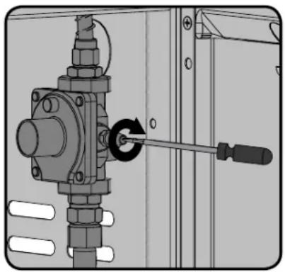
Mechanical assembly diagram showing a bolted joint with a screwdriver inserted, no text or symbols presentThis unit includes an internal regulator which stabilizes the gas pressure and improves grill performance. This regulator cannot be adjusted. There is a pressure tap located on the side of the regulator. It can be used by a qualified service person when servicing the grill to determine if the regulator is functioning properly. The screw within the pressure tap must always be kept tight, except when performing a pressure test on the regulator (qualified service personnel only).





Leak Testing Instructions
WARNING! A leak test must be performed annually and each time a cylinder is hooked up or if a part of the gas system is replaced.
WARNING! Never use an open flame to check for gas leaks. Be certain no sparks or open flames are in the area while you check for leaks. Sparks or open flames will result in a fire or explosion, damage to property, serious bodily injury, or death.
Leak testing: This must be done before initial use, annually, and whenever any gas components are replaced or serviced. Do not smoke while performing this test, and remove all sources of ignition. See Leak Testing Diagram for areas to check. Turn all burner controls to the off position. Turn gas supply valve on.
Brush a half-and-half solution of liquid soap and water onto all joints and connections of the regulator, hose, manifolds and valves.
Bubbles will indicate a gas leak. Either tighten the loose joint or have the part replaced with one recommended by the Napoleon Customer Solutions department and have the grill inspected by a certified gas installer.
If the leak cannot be stopped, immediately shut off the gas supply, disconnect it, and have the grill inspected by a certified gas installer or dealer. Do not use the grill until the leak has been corrected.
Lighting Instructions
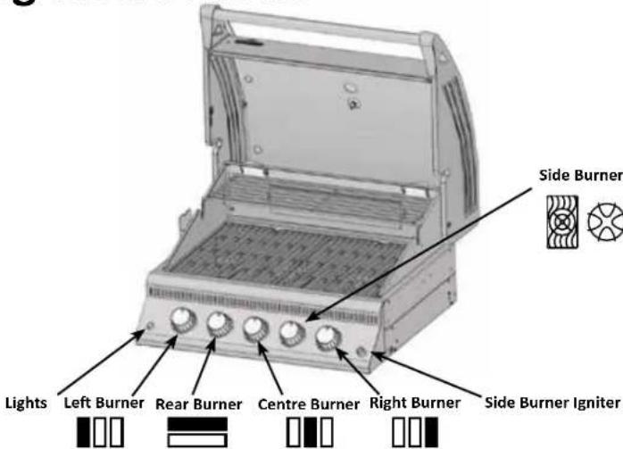
EN

WARNING! Open lid.
Off Position
WARNING! Ensure all burner controls are in the off position. Turn on the gas supply valve.
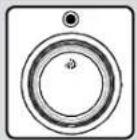
| Main Tube Burner Lighting | Rear Burner Lighting (If equipped) | Side Burner Lighting (If equipped) |
| 1. Open grill lid. 1. Open grill lid. 1. Open side burner cover. | ||
| 2. Push and turn any main burner knob slowly to the ‘hi’ position. This action will ignite the pilot flame which will in turn light the selected burner. If the pilot lights, continue to push down on the control knob until the burner lights and then release. | 2. Remove the warming rack 2. Push and turn side burner control to high position. | |
| 3. If the pilot does not ignite, then immediately turn the control knob back to the ‘off position and repeat step 2 several times. | 3. Clip a match into the supplied lighting rod. Hold a lit match to right end ports of rear burner. Turn rear burner to high. | 3. Press and hold igniter button until burner lights, or light by match |
| 4. If the pilot and burner will not ignite within 5 seconds, turn the control knob to the ‘off’ position and wait 5 minutes for any excess gas to dissipate. Either repeat steps 2 and 3 or light with a match. | 4. If the burner will not ignite within 5 seconds, turn the control knob to the ‘off’ position and wait 5 minutes for any excess gas to dissipate. Either repeat steps 2 and 3 or light with a match. | |
| 5. If lighting the unit with a match, clip the match into the supplied lighting rod. Hold the lit match down through the grill and sear plate while turning the corresponding burner valve to high. | ||
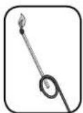

WARNING! Do not use the rear burner (rotisserie burner) with the main burners operating.
Operating The Grill
Initial Lighting: When lit for the first time, the gas grill emits a slight odor. This is a normal temporary condition caused by the "burn-in" of internal paints and lubricants used in the manufacturing process and does not occur again. Simply run the main burners on high for approximately one-half hour.
Main Burner Use: When searing foods, we recommend preheating the grill by operating all main burners in the high position with the lid closed for approximately 10 minutes. Food cooked for short periods of time (fish, vegetables) can be grilled with the lid open. Cooking with the lid closed will ensure higher, more even temperatures that can reduce cooking time and cook meat more evenly. Food that has a cooking time longer than 30 minutes, such as roasts, can be cooked indirectly (with the burner lit opposite to the food placement). When cooking very lean meats, such as chicken breasts or lean pork, the grids can be oiled before pre-heating to reduce sticking. Cooking meat with a high degree of fat content can create flare-ups. Either trim the fat or reduce temperatures to inhibit this. Should a flare-up occur, move food away from the flames and reduce the heat. Leave the lid open. See Your All Season Grill cookbook by Napoleon for more detailed instructions.
Direct Cooking: Place food to be cooked on the grill directly over the heat. This method is generally used for searing or for foods that do not require prolonged cooking times such as hamburgers, steaks, chicken pieces, or vegetables. The food is first seared to trap-in the juices and flavor, and then the temperature is lowered to finish cooking the food to your preference.
Indirect Cooking: With one or more burners operating, place food to be cooked on the grill over a burner that is not operating. The heat circulates around the food, cooking slowly and evenly. Cooking with this method is much the same as cooking in your oven and is generally used for larger cuts of meats such as roasts, chickens or turkeys, but can also be used for cooking foods that are prone to flare-ups or for smoking foods. Lower temperatures and slower cooking times result in tender foods.
Rear Burner Use (If Equipped): Remove the warming rack prior to use, the extreme heat will damage the warming rack. Cooking grids should also be removed if they interfere with the rotisserie. The rear burner is designed to be used in conjunction with the rotisserie kit available from your dealer. See the rotisserie kit assembly instructions.
To use the counterbalance - remove the rotisserie motor from the gas grill. Place the spit with meat being cooked across the hangers inside the grill. The meat will naturally hang with the heavy side down. Tighten the counterbalance arm and weight so the arm is facing up. Slide the counterweight in or out to balance the load and tighten in place. Re-install the motor and begin cooking. Place a metal dish underneath the meat to collect drippings for basting and naturally delicious gravy. Basting liquid may be added as required. To seal in juices, first operate rear burner on high until brown, then reduce the heat to thoroughly cook foods. Keep the lid closed for best results. Your roasts and fowl will brown perfectly on the outside and stay moist and tender on the inside. For example, a 3 pound chicken on the rotisserie will be done in approximately 1 12 hours on medium to high. See 'Your all Season Grill' cookbook by Napoleon for more detailed instructions.

WARNING! Barbecue sauce and salt can be corrosive and will cause rapid deterioration of the gas grill components unless cleaned regularly. When finished cooking disassemble rotisserie components, wash thoroughly with warm soapy water and store indoors.
Flame Side Burner Use (if equipped): The side burner can be used like any stove top burner, for gravies, soups etc. For best performance, the gas grill should be located with the side burner protected from the wind. The recommended pan diameter is 200 to 250 mm.

WARNING! Never grill food directly on the side burner grate. It is designed for use with pots and pans only.
WARNING! Do not close the side burner lid while it is operating or hot.
WARNING! Do not use side burner to deep fry foods as cooking with oil can create a dangerous situation.
Infrared Side Burner Use(if equipped): The gas grill should be located so that the side burner is protected from the wind, because the wind will adversely affect its performance.
The side burner is equipped with a cooking grid which can be positioned at two different heights. The lower position can be used like any range top burner, for gravies, soups, etc. The higher position is for searing meats. (see instructions located on side burner lid).

WARNING! Do not close the side burner lid while it is operating or hot.
WARNING! Do not adjust cooking grid while hot or operating.
WARNING! Do not use side burner to deep fry foods as cooking with oil can create a dangerous situation.

- Follow the infrared side burner lighting instructions and operate on high for 5 minutes with the lid opened or until the ceramic burners glow red.
- Place food on grills and cook according to times listed in the Infrared Grilling Chart.
- Depending upon your taste, continue cooking over infrared burners on high, medium or low, turning food frequently, or place food on the main burner area of the grill, close lid, and allow oven temperature to slowly finish cooking your food.
CAUTION! Due to the intense heat the infrared burners provide, food left unattended over burners will burn quickly. Keep the lid open when cooking with the infrared burners on high. The intense heat ensures adequate searing temperatures even with the lid open. This also allows observation of the food, so as to prevent burning.
Protection Of Your Infra Red Burners: The infrared burners of your grill are designed to provide a long service life. However, there are steps you must take to prevent cracking of their ceramic surfaces, which will cause the burners to malfunction.
- Never let water come in direct contact with your ceramic burner.
- Do not allow hard objects to impact the infra red burner.
- Do not allow cold water (rain, sprinkler, hose, etc.) to come in contact with hot ceramic burners. A large temperature differential can cause cracking of the ceramic tile.
- Keep the lid closed when the side burner is not in use.
• After cooking operate the burner on high for 5 minutes, to burn off any drippings and debris.
Damage caused by failure to follow these steps is not covered by your grill warranty.
natural_image
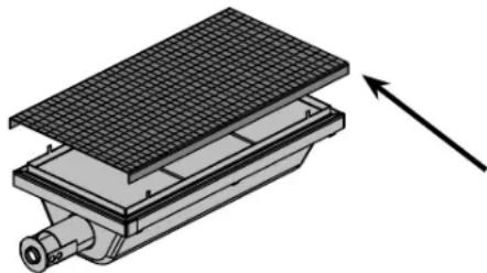
3D diagram of a mechanical device with grid pattern and directional arrow (no text or symbols)Replacement Screen N565-0002
Infrared Heat
Most people don't realize that the heat source we are most familiar with, our sun, warms the earth using mainly infrared energy. This is a form of electro-magnetic energy with a wavelength just greater than the red end of the visible light spectrum but less than a radio wave. This energy was discovered in 1800 by Sir William Herschel who dispersed sunlight into its component colors using a prism. He showed that most of the heat in the beam fell into the spectral region just beyond the red end of the spectrum, where no visible light existed. Most materials readily absorb infrared energy in a wide range of wavelengths, causing an increase in its temperature. The same phenomenon causes us to feel warmth when we are exposed to sunlight. The infrared rays from the sun travel through the vacuum of space, through the atmosphere, and penetrate our skin. This causes increased molecular activity in the skin, which creates internal friction and generates heat, allowing us to feel warmth.
Foods cooked over infrared heat sources are heated by the same principle. Charcoal grilling is our most familiar choice for infrared cooking. The glowing briquettes emit infrared energy to the food being cooked with very little drying effect. Any juices or oils that escape from the food drip onto the charcoal and vaporize into smoke giving the food its delicious grilled taste. The Napoleon infrared burner cooks in the same way. In each burner, 10,000 ports – each with its own tiny flame – cause the surface of the ceramic tile to glow red. This glow emits the same type of infrared heat to the food as charcoal, without its hassle or mess. Infrared burners also provide a more consistently heated area that is far easier to regulate than a charcoal fire. For instant searing, the burners can be set to high, yet they can also be turned down for slower cooking. We all know how difficult that is on a charcoal fire. Traditional gas burners heat the food in a different way. The air surrounding the burner is heated by the combustion process and then rises to the food being cooked. This generates lower grill temperatures that are ideal for more delicate cuisine such as seafood or vegetables, whereas Napoleon's infrared burners produce searing heat for juicier, tastier steaks, hamburgers and other meats. For cooking times and tips refer to the Infrared Grilling Chart.
Infrared Grilling Chart
| Food Control | Setting Cooking Time Helpful Suggestions | ||
| Steak1 in. (2.54cm) thick | High setting 2 min. each side.High setting 2 min. each side then medium setting.High setting 2 min. each side then medium setting. | 4 min. – Rare6 min. – Medium8 min. – Well done | When selecting meat for grilling, ask for marbled fat distribution. The fat acts as a natural tenderizer while cooking and keeps it moist and juicy. |
| Hamburger1/2 in. (1.27cm) thick | High setting 2 min. each side.High setting 2 1/2 min. each side.High setting 3 min. each side. | 4 min. – Rare5 min. – Medium6 min. – Well done | Preparing hamburgers to order is made easier by varying the thickness of your patties. To add an exotic taste to your meat, try adding hickory-flavored woodchips to Napoleon's woodchip smoker. |
| Chicken pieces High setting 2 min. each side.then medium-low to low setting. | 20-25 min. The joint connecting the thigh and the leg from the skinless side should be sliced 3/4 of the way though for the meat to lay flatter on the grill. This helps it to cook faster and more evenly. To add a trademark taste to your cooking, try adding mesquite-flavoured woodchips to your Napoleon woodchip smoker, optional accessory. | ||
| Pork chops Medium 6 min. per side Trim off the excess fat before | grilling. Choose thicker chops for more tender results. | ||
| Spare ribs High setting for 5 minuteslow to finish | 20 min. per sideturn often | Choose ribs that are lean and meaty. Grill until meat easily pulls away from the bone. | |
| Lamb chops High setting for 5 minutesmedium to finish | 15 min. per side Trim off the excess fat before grilling. Choose extra thick chops for more tender results. | ||
| Hot dogs Medium - Low 4-6 min. Select the larger size wieners. | Slit the skin lengthwise before grilling. | ||
Maintenance / Cleaning Instructions
We recommend this gas grill be thoroughly inspected and serviced annually by a qualified service person.
At all times keep the gas grill area free from combustible materials, gasoline and other flammable vapors and liquids. Do not obstruct the flow of ventilation and combustion air. Keep the cylinder enclosure ventilation openings (located on the cart sides and at the front and back of the bottom shelf) free and clear from debris.

WARNING! Always wear protective gloves and safety glasses when servicing your grill.
WARNING! To avoid the possibility of burns, maintenance should be done only when the grill is cool. Avoid unprotected contact with hot surfaces. Ensure all burners are turned off. Clean grill in an area where cleaning solutions will not harm decks, lawns, or patios. Do not use oven cleaner to clean any part of this gas grill. Do not use a self-cleaning oven to clean cooking grids or any other parts of the gas grill. Barbecue sauce and salt can be corrosive and will cause rapid deterioration of the gas grill components unless cleaned regularly.
Note: Stainless steel tends to oxidize or stain in the presence of chlorides and sulfides, particularly in coastal areas and other harsh environments, such as the warm, highly humid atmosphere around pools and hot tubs. These stains could be perceived as rust, but can be easily removed or prevented. To provide stain prevention and removal, wash all stainless steel and chrome surfaces every 3-4 weeks or as often as required with fresh water and/or stainless steel cleaner.

WARNING! Turn off the gas at the source and disconnect the unit before servicing. To avoid the possibility of burns, maintenance should be done only when the grill is cool. A leak test must be performed annually and whenever any component of the gas train is replaced or gas smell is present.
Grids And Warming Rack: The grids and warming rack are best cleaned with a brass wire brush during the pre-heating period. Steel wool can be used for stubborn stains. It is normal that stainless grids (if equipped) will discolor permanently from regular usage due to the high temperature of the cooking surface.
Cast Iron Cooking Grids: The cast iron cooking grids supplied with your new grill offer superior heat retention and distribution. By regularly seasoning your grids you are adding a protective coating, which will aid in resisting corrosion and increase your grids non-stick capabilities.
First Time Use: Wash the cooking grids by hand with mild dish soap and water to remove any residue from the manufacturing process (never wash in a dish washer). Rinse thoroughly with hot water and dry completely with a soft cloth. This is important to avoid moisture from entering the cast iron.
Seasoning: Using a soft cloth, spread VEGETABLE SHORTENING over the entire grid surface ensuring all grooves and corners are covered. Do not use salted fats such as butter or margarine. Pre-heat your grill for 15 minutes, then place the seasoned cooking grids in the grill. Turn the burner control knobs to medium with the lid closed. Allow the cooking grids to heat for approximately one-half hour. Turn all the burners to the "OFF" position and turn the gas off at the source. Let the cooking grids stand until cool. This procedure should be repeated several times throughout the season, although it is not required for daily use (follow daily usage procedure below).
Daily Usage: Before pre-heating, and cleaning with a brass wire grill brush, coat the entire top surface of the cooking grids with VEGETABLE SHORTENING. Pre-heat the grill and then brush away any unwanted residue with a brass wire brush.
Stainless Steel Cooking Grids: (upgrade kit available - see replacement parts list). Stainless steel cooking grids are durable and corrosion resistant. They require less seasoning and maintenance than cast iron cooking grids. It is recommended that you follow the daily usage procedure listed above although you may find pre-heating and cleaning your grids with a wire brush is sufficient for your grilling needs.
Control Panel: The control panel text is printed directly on the stainless steel and with proper maintenance will remain dark and legible. To clean the panel, use only warm soapy water or stainless steel cleaner available from your Napoleon dealer. Never apply abrasive cleaners on any stainless surfaces, especially the printed portion of the control panel or the printing will gradually rub off.
Cleaning Inside The Gas Grill: Remove the cooking grids. Use a brass wire brush to clean loose debris from the casting sides and underneath the lid. Scrape the sear plates with a putty knife or scraper, and use a wire brush to remove the ash. Remove the sear plates and brush debris from the burners with the brass wire brush. Sweep all debris from inside the gas grill into the drip pan.
Lights: To remove the lens from the light housing, insert a flat screwdriver tip between the lens and the housing and rock it gently. Do not touch the halogen bulb. The oil from your fingertips will reduce the
www.napoleongrills.com

life of the bulb. To clean the lens, first soak it in hot soapy water, then clean with a rag and non abrasive cleaner. To reinstall the lens, simply snap it back into the housing.
WARNING! Accumulated grease is a fire hazard.
Drip Pan: Clean the drip pan frequently (every 4 – 5 uses or as often as required) to avoid grease buildup. Grease and excess drippings pass through to the drip pan, located beneath the gas grill and accumulate in the disposable grease tray below the drip pan. To access the disposable grease tray or to clean the drip pan, slide the drip pan free of the grill. Never line the drip pan with aluminum foil, sand or any other material as this could prevent the grease from flowing properly. The pan should be scraped out with a putty knife or scraper. Replace the disposable grease tray every 2 – 4 weeks, depending on gas grill usage.
Cleaning The Outer Grill Surface: Do not use abrasive cleaners or steel wool on any painted, porcelain or stainless steel parts of your Napoleon Grill. Doing so will scratch the finish. Exterior grill surfaces should be cleaned with warm soapy water while the metal is still warm to the touch. To clean stainless surfaces, use a stainless steel or a non-abrasive cleaner. Always wipe in the direction of the grain. Over time, stainless steel parts discolor when heated, usually to a golden or brown hue. This discoloration is normal and does not affect the performance of the grill. Porcelain enamel components must be handled with additional care. The baked-on enamel finish is glass-like, and will chip if struck. Touch-up enamel is available from your Napoleon Grill dealer.

WARNING! Hose: Check for abrasions, melting, cuts, and cracks in the hose. If any of these conditions exist, do not use the gas grill. Have the part replaced by your Napoleon Grill dealer or qualified gas installer.
Side Burner: After cooking, it is recommended to leave the side burner operating on high until anything which may have spilled on the burner has burned off. The outer ring of the burner can be cleaned with a brass wire brush. Never brush the center portion of the burner as this will damage the ceramic. If the ports in the outer ring begin to close due to corrosion or drippings, use an opened paperclip or the supplied port maintenance bit to clean them. Drill out blocked ports using this drill bit in a small cordless drill.
Tube Burner: The burners are made from heavy wall 304 stainless steel, but extreme heat and a corrosive environment can cause surface corrosion to occur. This can be removed with a brass wire brush.

CAUTION! Beware of Spiders.
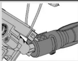
Spiders and insects are attracted to the smell of propane and natural gas. The burner is equipped with an insect screen on the air shutter, which reduces the likelihood of insects building nests inside the burner but does not entirely eliminate the problem. A nest or web can cause the burner to burn with a soft yellow or orange flame or cause a fire (flashback) at the air shutter beneath the control panel. To clean the inside of the burner, it must be removed from the gas grill: Remove the screw that attaches the burner to the back wall. Slide the burner back and upwards to remove. Cleaning: Use a flexible venturi tube brush to clean the inside of the burner. Shake any loose debris from the burner through the gas inlet. Check the burner ports and valve orifices for blockages. Burner ports can close over time due to cooking debris and corrosion, use an opened paperclip or the supplied port maintenance bit to clean them. Drill out blocked ports using this drill bit in a small cordless drill. The ports are easier to clean if the burner is removed from the grill, but it can also be done with the burner installed. Do not flex the drill bit when drilling the ports, as this will cause the drill bit to break. This drill is for burner ports only, not for the brass orifices (jets) which regulate the flow into the burner. Take care not to enlarge the holes. Ensure the insect screen is clean, tight, and free of any lint or other debris.
Reinstallation: Reverse the procedure to reinstall the burner. Check that the valve enters the burner when installing.

WARNING! When reinstalling the burner after cleaning it is very important that the valve/orifice enters the burner tube before lighting your gas grill. If the valve is not inside the burner tube a fire or explosion could occur.
natural_image
Mechanical assembly diagram showing a pipe joint with rotating components (no text or labels)Aluminum Castings: Clean castings periodically with warm soapy water. Aluminum will not rust, but high temperatures and weathering can cause oxidation to occur on aluminum surfaces. This appears as white spots on the castings. To refinish these areas, clean first and sand lightly with fine sandpaper. Wipe the surface to remove any residue and paint with high temperature barbecue paint. Protect surrounding areas from over-spray. Follow the manufacture's directions for curing.
Troubleshooting
| Problem Possible Causes Solution | ||
| Low heat / Low flame when valve turned to high. | For propane - improper lighting procedure.For natural gas - undersized supply line.For both gases - improper preheating. | Ensure lighting procedure is followed carefully. All gas grill valves must be in the off position when the tank valve is turned on. Turn tank on slowly to allow pressure to equalize. See lighting instructions.Pipe must be sized according to installation code.Preheat grill with both main burners on high for 10 to 15 minutes. |
| Excessive flare-ups/uneven heat. | Sear plates installed incorrectly.Improper preheating.Excessive grease and ash build on sear plates and in drip pan. | Ensure sear plates are installed with the holes towards the front and the slots on the bottom. See assembly instructions.Preheat grill with both main burners on high for 10 to 15 minutes.Clean sear plates and drip pan regularly. Do not line pan with aluminum foil. Refer to cleaning instructions. |
| Burners burn with yellow flame, accompanied by the smell of gas. | Possible spider web or other debris, or improper air shutter adjustment. | Thoroughly clean burner by removing. See general maintenance instructions. |
| Humming regulator. | Normal occurrence on hot days. | This is not a defect. It is caused by internal vibrations in the regulator and does not affect the performance or safety of the gas grill.Humming regulators will not be replaced. |
| Burners will not cross light each other. | Plugged ports at back of burner. Clean burner ports. See burner maintenance instructions. | |
| “Paint” appears to be peeling inside lid or hood. | Grease build-up on inside surfaces. This is not a defect. The finish on the lid and hood is porcelain, and will not peel. The peeling is caused by hardened grease, which dries into paint-like shards, that flake off. Regular cleaning will prevent this. See cleaning instructions. | |
| Infrared burner (if equipped) flashes back (during operation the burner abruptly makes a loud “whoosh” sound, followed by a continuous blow-torch type sound and grows dim.) | Ceramic tiles overloaded with grease drippings and build-up. Ports are clogged.Burner overheated due to inadequate ventilation (too much grill surface covered by griddle or pan.)Cracked ceramic tile.Leaking gasket surrounding the ceramic tile, or a weld failure in the burner housing. | Turn burner off and allow to cool for at least two minutes. Relight burner and burn on high for at least five minutes or until the ceramic tiles are evenly glowing red.Ensure that no more than 75% of the grill surface is covered by objects or accessories. Turn burner off and allow to cool for at least two minutes, then relight.Allow burner to cool and inspect very closely for cracks. If any cracks are found, contact your authorized Napoleon dealer to order a replacement burner assembly.Contact your authorized Napoleon dealer for instructions on ordering a replacement burner assembly. |
KEEP YOUR RECEIPT AS PROOF OF PURCHASE TO VALIDATE YOUR WARRANTY.
Ordering Replacement Parts
Warranty Information
MODEL: ____
DATE OF PURCHASE: ____
SERIAL NUMBER: ____
(Record information here for easy reference)
Before contacting the Customer Solutions Department, check the Napoleon Website for more extensive cleaning, maintenance, troubleshooting and parts replacement instructions at www.napoleongrills.com. Contact your local distributor directly (refer to the distributor contact list provide with your grill) for replacement parts and warranty claims.
To process a claim, we must be provided with the following information:
- Model and serial number of the unit.
- Part number and description.
- A concise description of the problem ('broken' is not sufficient).
- Proof of purchase (photocopy of the invoice).
In some cases the Customer Solutions Representative could request to have the parts returned to the factory for inspection before providing replacement parts. These parts must be shipped prepaid to the attention of the Customer Solutions Department with the following information enclosed:
- Model and serial number of the unit.
- A concise description of the problem ('broken' is not sufficient).
- Proof of purchase (photocopy of the invoice).
- Return Authorization Number - provided by the Customer Solutions Representative.
Before contacting Customer Solutions Representative, please note that the following items are not covered by the warranty:
• Costs for transportation, brokerage or export duties.
• Labor costs for removal and reinstallation.
• Costs for service calls to diagnose problems.
• Discoloration of stainless steel parts.
- Part failure due to lack of cleaning and maintenance, or use of improper cleaners (oven cleaner).
natural_image
Illustration of a modern stainless steel electric grill with control panel and side grilles (no text or symbols)
LE485SB, LE485RSB, LE485RSIB

GEFAHR
natural_image
Mechanical assembly diagram showing a valve mechanism with a screwdriver (no text or labels)natural_image
Mechanical assembly diagram showing a hand operating a cylindrical component with attached parts (no text or symbols visible)CAUTION! During unpacking and assembly we recommended you wear work gloves and safety glasses for your protection. Although we make every effort to make the assembly process as problem free and safe as possible, it is characteristic of fabricated steel parts that the edges and corners might be sharp and could cause cuts if handled incorrectly.
Getting Started
- Remove all cart panels, hardware, and grill head from carton. Raise lid and remove any components packed inside. Use the parts list to ensure all necessary parts are included.
- Do not destroy packaging until the grill has been fully assembled and operates to your satisfaction.
- Assemble the grill where it is to be used, lay down cardboard or a towel to protect parts from being lost or damaged while assembling.
- Most stainless steel parts are supplied with a protective plastic coating that must be removed prior to using the grill. The protective coating has been removed from some of the parts during the manufacturing process and may have left behind a residue that can be perceived as scratches or blemishes. To remove the residue, vigorously wipe the stainless steel in the same direction as the grain.
- Follow all instructions in the order that they are laid out in this manual.
- Two people are required to lift the grill head onto the assembled cart.
If you have any questions about assembly or grill operation, or if there are damaged or missing parts please call our Customer Solutions Department at 1-866-820-8686 between 9 AM and 5 PM (Eastern Standard Time)


TOOLS REQUIRED FOR ASSEMBLY (tools not included)
natural_image
Sequence of grayscale icons showing different tools: screwdriver, wrench, screwdriver, pen, hammer, and pliers (no text or symbols)www.napoleongrills.com
32


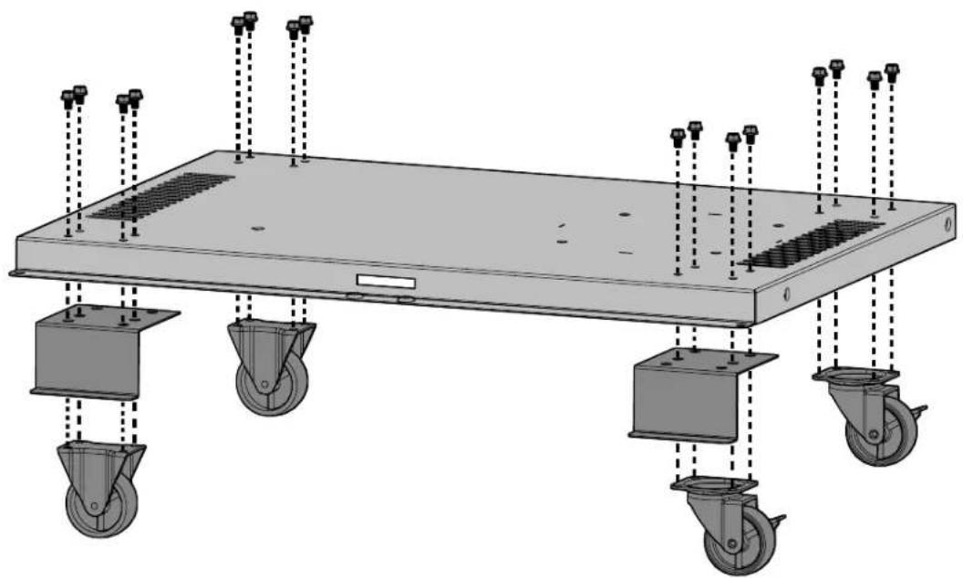
natural_image
Technical illustration of a mechanical support system with wheels and mounting feet (no text or symbols)
non revolving caster- left side
natural_image
Diagram of a mechanical or electrical component with wiring and mounting holes, no visible text or symbols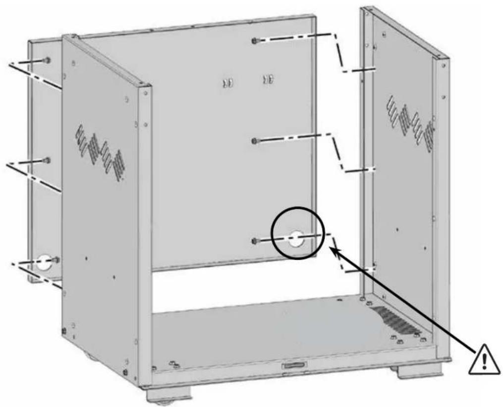
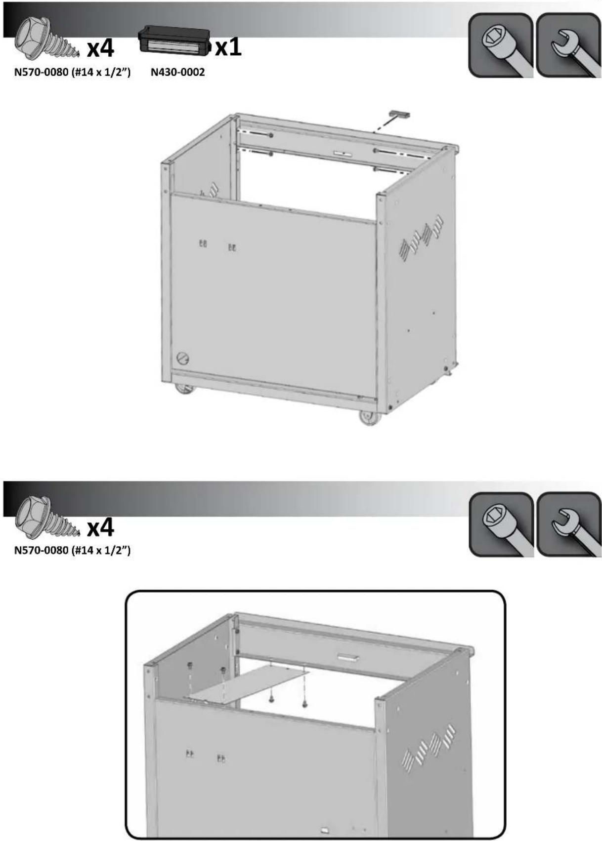
N570-0091 (1/4-20 X 1/2")

WARNING! Propane Only - To avoid assembly difficulties, prior to mounting the grill head, remove zip tie holding regulator. This was installed at the factory to protect the regulator hose during shipping and is no longer required. (Take care when removing the tie not to damage the hose). Ensure the regulator hose does not become pinched between the grill head and the cart.
All cylinders 7kg or larger must be placed outside the enclosure (under the right side shelf) on level ground. The hose assembly must be routed through the knock out hole in the right side panel.
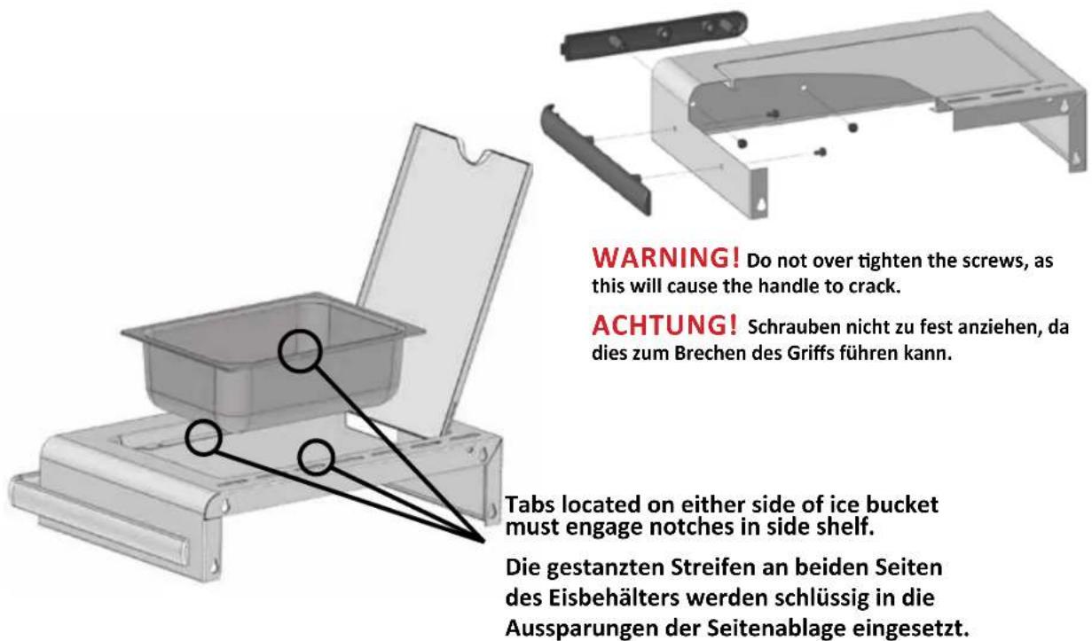
WARNING! Do not over tighten the screws, as this will cause the handle to crack.
natural_image
Technical diagram of a mechanical bracket assembly with mounting flanges and internal components (no text or labels)
LE485RSIB MODEL
LE485RSIB MODELLEN
natural_image
Illustration of a hexagonal bolt and a separate plate (no text or symbols)N570-0082 (1/4-20 X 5/8") N735-0001
natural_image
Close-up of a metallic mechanical component with two circular features and mounting holes (no text or symbols visible)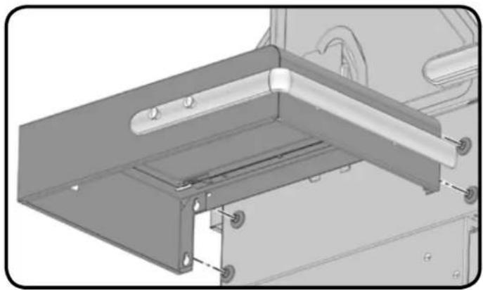
natural_image
Mechanical assembly diagram showing a bracket with mounting holes and a car wheel (no text or symbols)
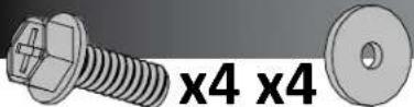
N570-0082 (1/4-20 X 5/8") N735-0001
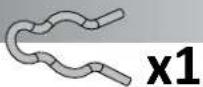
N160-0023
LE485RSIB MODEL
LE485RSIB MODELLEN
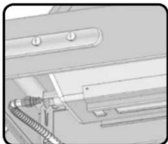
natural_image
Pure mechanical component diagram without any text, numbers, or symbolsnatural_image
Technical illustration of a vehicle chassis frame with mounting brackets and structural components (no text or symbols)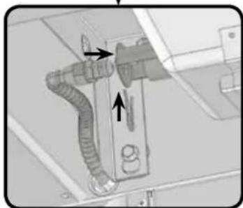
natural_image
Diagram of a mechanical ventilation system with pipes and housing (no text or labels)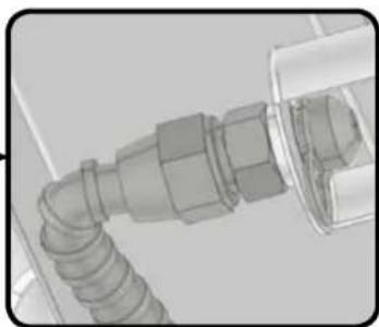
natural_image
Close-up of a mechanical pipe fitting with threaded end (no visible text or symbols)natural_image
Close-up of a mechanical component with a coiled spring or hose assembly (no visible text or symbols)natural_image
Mechanical assembly diagram showing internal components and mounting brackets (no text or symbols)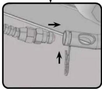
natural_image
Diagram of a mechanical component with arrows indicating direction (no text or symbols)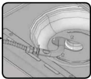
natural_image
Technical illustration of a mechanical component with no visible text or symbols
natural_image
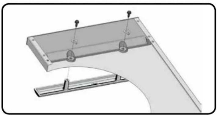
Technical diagram of a mechanical bracket assembly with mounting holes and a curved base (no text or symbols)
42
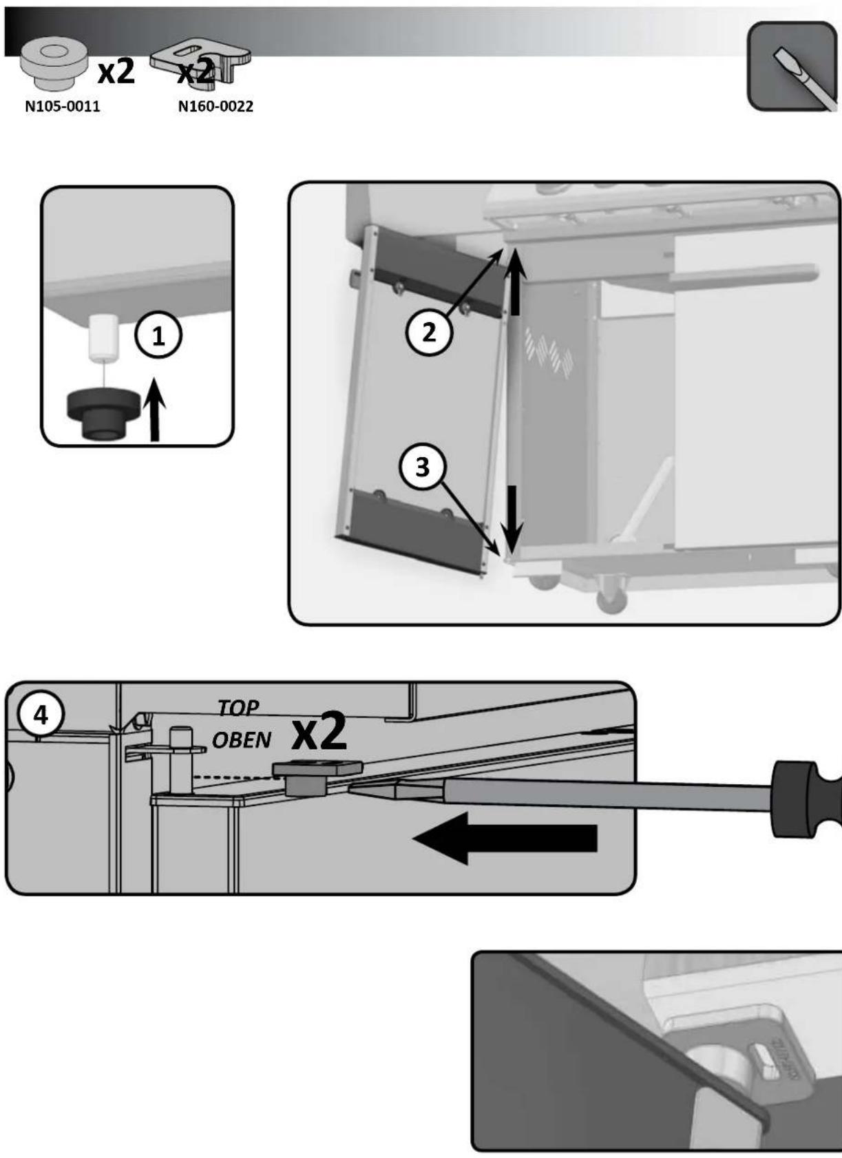
x2

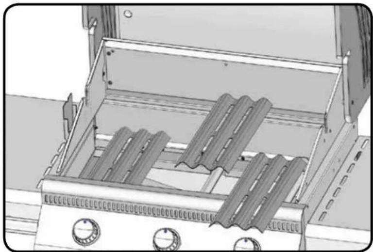
natural_image
Illustration of a portable stove interior with grilles and control knobs (no text or symbols)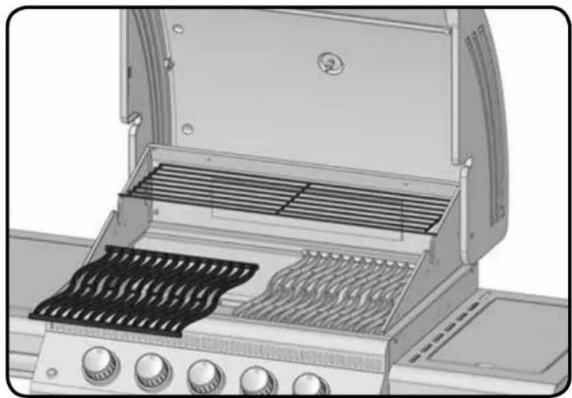
natural_image
Exterior view of a portable electric stove grater with open door and side-mounted grilles (no text or symbols visible)
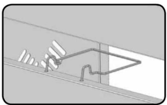
natural_image
Diagram of a mechanical or structural assembly with no visible text, numbers, or symbols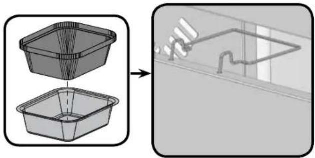
natural_image
Diagram showing two 3D plastic containers with a wire meshing process on the right, no text or symbols present.
natural_image
Blank gradient bar with no text, symbols, or discernible features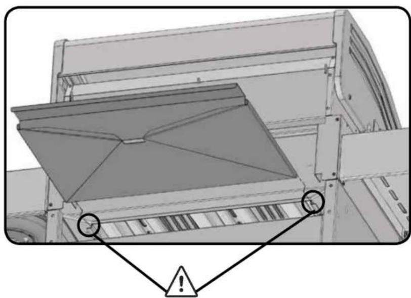
natural_image
Technical diagram of a mechanical device with warning symbols (no readable text or labels)Rotisserie Kit Assembly Instruction
(optional)
Assemble rotisserie kit components as shown.
Providing Power To The Internal Lights
(485RSIB MODEL ONLY)
CAUTION! To ensure protection against electric shock, use only a Ground Fault Interrupter (GFI) protected circuit with this outdoor gas cooking appliance.
To provide power to the internal lights, plug the transformer cord into a grounded electrical cord. The light switch located on the control panel allows you to easily turn the internal lights on and off.
- Ensure the cord is approved and marked for OUTDOOR USE.
- Do not immerse cord or plugs in water or other liquid.
- Keep electrical cords out of pathways.
- Do not let the cord hang over the edge of a table or touch hot surfaces.
natural_image
Exterior view of a gray industrial machine with wheels and a cable (no visible text or symbols)natural_image
Technical diagram of an electrical enclosure with multiple rotary switches and a curved pipe connection (no text or symbols)Ensure the regulator drops into the small opening, between the tank heat shield and the right side of the cabinet.
natural_image
Interior view of a water pump system with control panel and storage tanks (no visible text or labels)Propane Only – Improper Hose Connection
WARNING - FIRE HAZARD
The regulator must be attached so that no part of the hose touches the underside of the grill or drip pan. A fire will result if these directions are ignored.

www.napoleongrills.com
Natural Gas Only – Proper Hose Connection
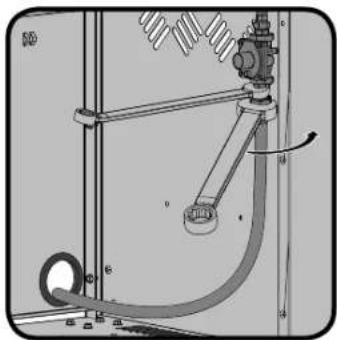
WARNING! The installation must be performed by a licensed gas fitter, and all connections must be leak tested before operating the grill. Do not use pipe dope or teflon tape on this connection. Tighten the connection with two wrenches.
natural_image
Interior view of an industrial enclosure with a curved pipe and mechanical components (no visible text or symbols)
16 mm
20 mm
natural_image
Technical diagram of a mechanical or electrical assembly with pipes and components (no visible text or symbols)Bushing is pre-installed at factory.
WARNING - FIRE HAZARD
WARNING! Do not route hose underneath drip pan.

WARNING! Do not route hose over top of rear panel.

WARNING! Ensure the hose does not contact any high temperature surfaces, or it may melt and leak causing a fire.
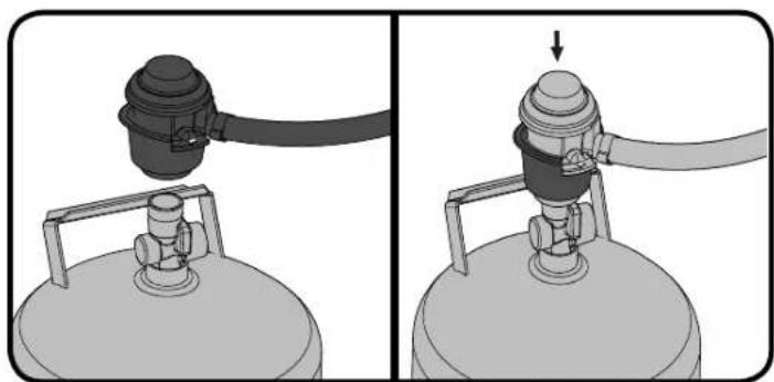
NOTE! Some regulator hoses contain a nut and a left hand thread, and others must press ON to connect and OFF to detach. Follow the instructions provided below for the appropriate regulator hose.
natural_image
Two-panel illustration of a gas cylinder device with attached tubing, showing internal components and no text or symbols.FIG. 1
FIG. 2

natural_image
Two-panel illustration showing a gas cylinder being handled with a valve, no text or symbols present.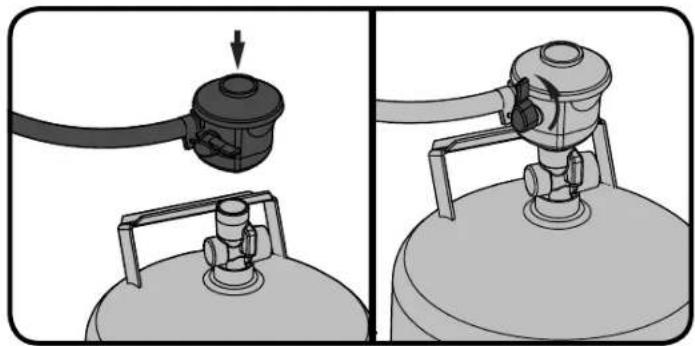
natural_image
Two-step diagram showing a gas cylinder being inserted into a tank, with no text or symbols present.FIG.3
FIG.4
natural_image
Two-step diagram showing a gas cylinder being inserted into a valve, with no text or symbols present.Leak Testing Instructions

WARNING! A leak test must be performed annually and each time a cylinder is hooked up or if a part of the gas system is replaced.

WARNING! Never use an open flame to check for gas leaks. Be certain no sparks or open flames are in the area while you check for leaks. Sparks or open flames will result in a fire or explosion, damage to property, serious bodily injury, or death.

Leak testing: This must be done before initial use, annually, and whenever any gas components are replaced or serviced. Do not smoke while performing this test, and remove all sources of ignition. See Leak Testing Diagram for areas to check. Turn all burner controls to the off position. Turn gas supply valve on.

Brush a half-and-half solution of liquid soap and water onto all joints and connections of the regulator, hose, manifolds and valves.

Bubbles will indicate a gas leak. Either tighten the loose joint or have the part replaced with one recommended by the Napoleon Customer Solutions department and have the grill inspected by a certified gas installer.
If the leak cannot be stopped, immediately shut off the gas supply, disconnect it, and have the grill inspected by a certified gas installer or dealer. Do not use the grill until the leak has been corrected.

LE485SB Parts List / Stückliste
| Item Part | # Description LE485SB | ||
| 1 N135-003 | 8G lid side casting left x | ||
| 2 N135-003 | 9G lid side casting right x | ||
| 3 N335-005 | 0 stainless steel lid insert x | ||
| N335-0051K black lid insert x | |||
| 4 N585-006 | 6 lid heat shield x | ||
| 5 N510-001 | 3 black silicone lid bumper x | ||
| 6 N685-000 | 6 temperature gauge x | ||
| 7 N385-012 | 9 NAPOLEON logo x | ||
| 8 W450-000 | 5 logo spring clips x | ||
| 9 N010-065 | 2 lid handle x | ||
| 10 | N080-0252G lid handle cover x | ||
| 11 | N570-0015 lid pivot screw x | ||
| 12 | N570-0073 1/4-20 x 3/8" screw x | ||
| 13 | N735-0003 1/4" lockwasher x | ||
| 14 | N570-0091 #14 x 1/2" screw x | ||
| 15 | N570-0042 10-24 x 3/8" screw x | ||
| 16 | N520-0028K warming rack x | ||
| 17 | N475-0270K base insert right x | ||
| 18 | N035-0101 base side right x | ||
| 19 | N570-0093 M4 x 8mm" screw x | ||
| 20 | N450-0032 M4 lock nut x | ||
| 21 | N035-0102K base insert rear x | ||
| 22 | N200-0093-GY1SG rear corner cover base x | ||
| 23 | N570-0008 #8 x 1/2" screw x | ||
| 24 | N475-0269K base insert left x | ||
| 25 | N035-0100 base side left x | ||
| 26 | N475-0267 rotisserie mount x | ||
| 27 | N305-0063 cooking grids - cast iron x | ||
| N370-0597 cooking grids - stainless steel upgrade kit ac | |||
| 28 | N305-0057K sear plate x | ||
| 29 | N080-0250 main burner support x | ||
| 30 | N100-0036 main burner x | ||
| 31 | Z570-0039 1/4-20 x 3/8" screw x | ||
| 32 | N215-0008 grease deflector base x | ||
| 33 | N010-0501-M05 drip pan x | ||
| 34 | N735-0001 insulated washer x | ||
| 35 | N570-0082 1/4-20 x 5/8" screw x | ||
| 36 | N010-0643-M06 side shelf left x | ||
| 37 | Z340-0001 tool hook side shelf x | ||
| 38 | N570-0088 10-24 x 1/2" screw x | ||
| 39 | N735-0007 1/4" washer x | ||
| 40 | N380-0023-RD control knob x | ||
| 41 | N051-0011 control knob bezel x | ||
| 42 | N010-0664 manifold assembly c/w valves p | ||
| 43 | N120-0011 end cap control panel left x |
LE485SB Parts List / Stückliste
| Item Part | # Description LE485SB | ||
| 44 N585-00 | 65 base heat shield x | ||
| 45 N035-01 | 03K base insert front x | ||
| 46 N120-00 | 12 end cap control panel right x | ||
| 47 N325-00 | 62 side shelf handle x | ||
| 48 N475-02 | 77-GB-DE control panel x | ||
| 49 N655-01 | 24S front cabinet support x | ||
| 50 N475-02 | 36S left/right side panel cabinet enclosure x | ||
| 51 N160-00 | 14 grease tray holder | x | |
| 52 N185-00 | 01 grease tray foil | x | |
| N710-0062 grease tray a aluminium ac | |||
| 53 N160-00 | 22 clip door pivot pin | x | |
| 54 N475-02 | 71S rear cart panel | x | |
| 55 N080-02 | 54S propane tank inhibitor bracket p | ||
| 56 N120-00 | 19-GYOTX door end cap | x | |
| 57 N475-02 | 93-SV1SG door panel | x | |
| N475-0293-BK1SG cart door assembly black | x | ||
| 58 N105-00 | 11 door bushings | x | |
| 59 N340-00 | 07 tool hook | x | |
| 60 N570-00 | 99 #14 x 3/4" screw | x | |
| 61 N080-02 | 12S stabilizer brackets | x | |
| 62 N130-00 | 13 non revolving caster | x | |
| 63 N130-00 | 12 revolving caster | x | |
| 64 N585-00 | 64P heat shield | x | |
| 65 N590-01 | 47S bottom shelf | x | |
| 66 N430-00 | 02 magnetic catch | x | |
| 67 | W445-0021 | union fitting 3/8" - 3/8" | x |
| 68 N720-00 | 44 manifold flex connector | x | |
| 69 N530-00 | 23 step down regulator | p | |
| 70 N080-02 | 02-M01 cross light bracket | x | |
| 71 N010-06 | 42-M06 side shelf right | x | |
| 72 N530-00 | 37 regulator - United Kingdom dom | p | |
| N530-0032 regulator - Germany | p | ||
| N530-0046 regulator - Czech Republic | p | ||
| N530-0033 regulator - Holland | p | ||
| N530-0034 | regulator - Spain/Finland/Norway/Denmark | p | |
| N530-0035 regulator - Sweden | p | ||
| N530-0036 regulator - Italy | p | ||
| N530-0039 regulator - Hungary | p | ||
| N530-0042 regulator - Switzerland | p | ||
| N530-0043 regulator - Russia p | |||
| N530-0044 regulator - Poland | p | ||
| 73 N640-00 | 01 hose retainer clip | x | |
| 74 N105-00 | 13 bushing | x | |
| 75 N357-00 | 13 side burner igniter | x | |
| 76 N500-00 | 41K side burner plate x | ||
| 77 | N570-0019 | screw, 10-24 x 1/4" | x |
LE485SB Parts List / Stückliste
| Item Part | # Description LE485SB | ||
| 78 N100-00 | 37 side burner x | ||
| 79 N720-00 | 55 side burner supply tube x | ||
| 80 N750-00 | 16 side burner igniter lead x | ||
| 81 N305-00 | 59 side burner grate x | ||
| 82 N485-00 | 09 push pin x | ||
| 83 N335-00 | 48-M06 side burner lid x | ||
| 84 N105-00 | 01 bushing 7/8" x | ||
| 85 N455-00 | 62 orifice #60 p | ||
| 86 N160-00 | 23 side burner hose /orifice retainer clip x | ||
| 87 N570-00 | 80 #14 x 1/2" screw | x | |
| 88 N485-00 | 16 pivot pin door top | x | |
| 89 N485-00 | 17 pivot pin door bottom | x | |
| 90 | N570-0100 | screw, #8 X 1/2" flat head | x |
| 91 | N570-0078 | screw, M4 X 8mm | x |
| 92 N255-00 | 14 fitting | x | |
| 93 N555-00 | 25 lighting match rod | x | |
| N370-0585 main assemb | y blister pack | x | |
| 65233 | rotisserie kit UK | ac | |
| 65232 | rotisserie kit CE | ac | |
| 68489 | vinyl cover | ac | |
| 56018 | stainless steel griddle | ac | |
| 56040 | cast iron griddle | ac | |
| 67731 | charcoal tray | ac | |
| 62007 | replacement grease trays foil (5 pieces) | ac |
p - propane units only n - natural gas units only
x - standard ac - accessory
LE485RSB Parts List / Stückliste
| Item Part # | Description LE485 | RSB | |
| 1 N135-0038 | G lid side casting left x | ||
| 2 N135-0039 | G lid side casting right x | ||
| 3 N335-0050 | stainless steel lid insert x | ||
| N335-0051K black lid insert x | |||
| 4 N585-0066 | lid heat shield x | ||
| 5 N510-0013 | black silicone lid bumper x | ||
| 6 N685-0006 | temperature gauge x | ||
| 7 N385-0129 | NAPOLEON logo x | ||
| 8 W450-0005 | logo spring clips | x | |
| 9 N010-0652 | lid handle | x | |
| 10 | N080-0252G lid handle cover | x | |
| 11 | N570-0015 lid pivot screw | x | |
| 12 | N570-0073 1/4-20 x 3/8" screw | x | |
| 13 | N735-0003 1/4" lock washer x | ||
| 14 | N570-0091 #14 x 1/2" screw x | ||
| 15 | N570-0042 10-24 x 3/8" screw | x | |
| 16 | N520-0028K warming rack | x | |
| 17 | N475-0270K base insert right | x | |
| 18 | N035-0101 base side right x | ||
| 19 | N570-0093 screw M4 x 8mm | x | |
| 20 | N450-0032 M4 lock nut | x | |
| 21 | N035-0104K base insert rear | x | |
| 22 | N200-0093S | rear corner cover base | x |
| 23 | N570-0008 | #8 x 1/2" screw | x |
| 24 | N475-0269K base insert left | x | |
| 25 | N035-0100 base side left | x | |
| 26 | N475-0267 rotisserie mount | x | |
| 27 | N305-0063 cooking grids - cast iron | x | |
| N370-0597 cooking grids - stainless steel upgrade kit | ac | ||
| 28 | N305-0057K sear plate | x | |
| 29 | N080-0250 main burner support | x | |
| 30 | N100-0036 main burner x | ||
| 31 | Z570-0039 | 1/4-20 x 1/2" screw | x |
| 32 | N215-0008 | grease deflector base right | x |
| 33 | N010-0501-M05 | drip pan | x |
| 34 | N735-0001 insulated washer | x | |
| 35 | N570-0082 | 1/4-20 x 5/8" screw | x |
| 36 | N010-0643-M06 | side shelf left | x |
| 37 | Z340-0001 | tool hook side shelf | x |
| 38 | N570-0088 | screw 10-24 x 1/2" | x |
| 39 | N735-0007 1/4" washer | x | |
| 40 | N380-0023-CL | control knob | x |
| 41 | N051-0011 control knob bezel x | ||
| 42 | N010-0644 | manifold assembly c/w valves | P |
| N010-0645 manifold assembly c/w valves | n | ||
| 43 | N120-0011 | end cap control panel left | x |
www.napoleongrills.com
LE485RSB Parts List / Stückliste
| Item Part # | Description LE485 | RSB | |
| 44 N585-006 | 5 base heat shield x | ||
| 45 N035-010 | 3K base insert front x | ||
| 46 N120-001 | 2 end cap control panel right x | ||
| 47 N325-006 | 2 side shelf handle x | ||
| 48 N475-026 | 6-GB-DE control panel - UK x | ||
| 49 N655-012 | 4S front cabinet support x | ||
| 50 N475-023 | 6S left/right side panel cabinet enclosure x | ||
| 51 N160-001 | 4 grease tray holder | x | |
| 52 N185-000 | 1 grease tray foil | x | |
| N710-0062 grease tray aluminium | ac | ||
| 53 N160-002 | 2 clip door pivot pin | x | |
| 54 N475-027 | 1S rear cart panel | x | |
| 55 N080-025 | 4S propane tank inhibitor bracket | p | |
| 56 N120-001 | 9-GYOTX door end cap | x | |
| 57 N475-029 | 3-M06 door panel | x | |
| N475-0293-BK1SG | cart door assembly black | x | |
| 58 N105-001 | 1 door bushings | x | |
| 59 N340-000 | 7 tool hook | x | |
| 60 | N570-0099 | screw, #14 x 3/4" | x |
| 61 N080-021 | 2S stabilizer brackets x | ||
| 62 N130-001 | 3 non revolving caster | x | |
| 63 N130-001 | 2 revolving caster | x | |
| 64 N585-006 | 4P heat shield | x | |
| 65 N590-014 | 7S bottom shelf | x | |
| 66 N430-000 | 2 magnetic catch | x | |
| 67 | W445-0021 | union fitting 3/8" - 3/8" | x |
| 68 N720-004 | 4 manifold flex connector | x | |
| 69 N530-002 | 3-SER regulator step down | p | |
| N530-0026-SER regulator step down | n | ||
| 70 | N080-0202-M01 | main burner cross light bracket | x |
| 71 N010-064 | 2-M06 side shelf right | x | |
| 72 N530-003 | 7 regulator - United Kingdom | p | |
| N530-0032 regulator - Germany | p | ||
| N530-0046 regulator - Czech Republic | p | ||
| N530-0033 regulator -Holland | p | ||
| N530-0034 regulator -Spain/Finland/Norway/Denmark | p | ||
| N530-0035 regulator -Sweden | p | ||
| N530-0036 regulator -Italy | p | ||
| N530-0039 regulator -Hungary | p | ||
| N530-0042 regulator -Switzerland | p | ||
| N530-0043 regulator -Russia | p | ||
| N530-0044 regulator -Poland p | |||
| 73 N640-000 | 1 hose retainer clip | x | |
| 74 N105-001 | 3 bushing | x | |
| 75 N660-000 | 2 switch light | x | |
| 76 N357-001 | 3 side burner igniter | x | |
www.napoleongrills.com
LE485RSB Parts List / Stückliste
| Item Part # | Description LE485 | RSB | |
| 77 N500-004 | 1K side burner plate x | ||
| 78 N570-003 | 9 screw 10-24 x 1/4" x | ||
| 79 N100-003 | 7 side burner x | ||
| 80 N720-005 | 5 side burner supply tube x | ||
| 81 N750-001 | 6 side burner igniter lead x | ||
| 82 N305-005 | 9 side burner grate x | ||
| 83 N485-000 | 9 push pin x | ||
| 84 N335-004 | 8-M06 side burner lid x | ||
| 85 N105-000 | 1 bushing 7/8" x | ||
| 86 N455-006 | 2 side burner orifice #60 p | ||
| N455-0063 side bur her orifice 1.45 mm n | |||
| N725-0040 side bur her valve p | |||
| N725-0041 side bur her valve n | |||
| 87 | N160-0023 | side burner hose/orifice retainer clip | x |
| 88 N190-000 | 1 battery pack | x | |
| W043-0002 | battery "AA' | x | |
| 89 N750-002 | OB wiring harness led | x | |
| 90 N010-066 | OP infra red rear burner p | ||
| N010-0660N | infra red rear burner | n | |
| N570-0094 M5 x 10 mm screw | x | ||
| N450-0033 M5 locking nut | x | ||
| 91 N455-005 | 4 rear burner orifice #59 | p | |
| N455-0053 rear bur her orifice #53 | n | ||
| 92 N720-005 | 3 rear burner supply tube | x | |
| 93 N010-065 | 1 grease deflector base left | x | |
| 94 N585-006 | 8 rear burner rain sheld | x | |
| 95 N485-001 | 6 pivot pin door top | x | |
| 96 N485-001 | 7 pivot pin door bottom | x | |
| 97 N570-008 | 0 1/4-20 x 1/2" screw | x | |
| 98 N570-007 | 8 M4 x 8mm screw | x | |
| 99 | N570-0100 | screw, #8 x 1/2" flat head | x |
| 100 | N555-0025 | lighting match rod | x |
| 101 | N255-0014 fitting | x | |
| N370-0585 main assembly blister pack | x | ||
| N555-0025 lighting rod x | |||
| 65233 | rotisserie kit UK | ac | |
| 65232 | rotisserie kit CE | ac | |
| 68489 | vinyl cover | ac | |
| 56018 | stainless steel griddle | ac | |
| 56040 | cast iron griddle | ac | |
| 67731 | charcoal tray | ac | |
| 62007 | replacement grease trays foil (5 pieces) | ac |
p - propane units only
n - natural gas units only
LE485RSIB Parts List / Stückliste
| Item Part | # Description LE485 | RSIB | |
| 1 N135-003 | 8G lid side casting left x | ||
| 2 N135-003 | 9G lid side casting right x | ||
| 3 N335-005 | 0 stainless steel lid insert x | ||
| N335-0051K black lid insert | |||
| 4 N585-006 | 6 lid heat shield x | ||
| 5 N510-001 | 3 black silicone lid bumper x | ||
| 6 N685-000 | 6 temperature gauge x | ||
| 7 W450-000 | 5 logo spring clips x | ||
| 8 N385-013 | 0 NAPOLEON logo | x | |
| 9 N010-065 | 2 lid handle | x | |
| 10 | N080-0252G lid handle cover | x | |
| 11 | N570-0015 lid pivot screw | x | |
| 12 | N570-0073 1/4-20 x 3/8" screw | x | |
| 13 | N735-0003 1/4" lockwasher | x | |
| 14 | N570-0091 #14 x 1/2" screw | x | |
| 15 | N570-0042 10-24 x 3/8" screw | x | |
| 16 | N520-0028K warming rack x | ||
| 17 | N475-0270K base insert right | x | |
| 18 | N035-0101 base side right | x | |
| 19 | N570-0093 screw M4 x 8mm | x | |
| 20 | N450-0032 lock nut M4 | x | |
| 21 | N035-0105K base insert rear | x | |
| 22 | N200-0092-GY1SG | rear cover base | x |
| 23 | N570-0008 | #8 x 1/2" screw | x |
| 24 | N475-0269K base insert left | x | |
| 25 | N035-0100 base side left | x | |
| 26 | N475-0267 rotisserie mount x | ||
| 27 | N305-0063 cooking grids - cast iron | x | |
| N370-0597 cooking grids - stainless steel upgrade kit | ac | ||
| 28 | N305-0057-M05 | sear plate | x |
| 29 | N080-0250 main burner support | x | |
| 30 | N100-0036 main burner x | ||
| 31 | N215-0008 | grease deflector base right | x |
| 32 | N010-0501-M05 | drip pan | x |
| 33 | N735-0001 insulated washer | x | |
| 34 | N570-0082 | 1/4-20 x 5/8" screw | x |
| 35 | N010-0641-M06 | side shelf left | x |
| 36 | Z340-0001 | tool hook side shelf | x |
| 37 | N380-0023-CL control knob | x | |
| 38 | N051-0011 control knob bezel | x | |
| 39 | N010-0644 | manifold assembly c/w valves | P |
| N010-0645 manifold assembly c/w valves | n | ||
| 40 | N120-0011 | end cap control panel left | x |
| 41 | N585-0065 base heat shield | x |
LE485RSIB Parts List / Stückliste
| Item Part | # Description LE485RSIB | |||
| 42 N035-01 | 03K base insert front x | |||
| 43 N120-00 | 12 end cap control panel right x | |||
| 44 N325-00 | 62 door handle x | |||
| 45 N475-02 | 83-GB-DE control panel x | |||
| 46 N655-01 | 24S front cabinet support x | |||
| 47 N475-02 | 36S left/right side panel cabinet enclosure x | |||
| 48 N160-00 | 14 grease tray holder x | |||
| 49 N185-00 | 01 grease tray foil | x | ||
| N710-0062 grease tray aluminium ac | ||||
| 50 N475-02 | 93-M06 door panel | x | ||
| 51 N475-02 | 71S rear cart panel | x | ||
| 52 N080-02 | 54S propane tank inhibitor bracket | p | ||
| 53 N120-00 | 19-GYOTX door end cap x | |||
| 54 N105-00 | 11 door bushings | x | ||
| 55 N080-02 | 12S stabilizer brackets | x | ||
| 56 N130-00 | 13 non revolving caster | x | ||
| 57 N130-00 | 12 revolving caster | x | ||
| 58 N585-00 | 64P heat shield | x | ||
| 59 N590-01 | 47S bottom shelf | x | ||
| 60 N430-00 | 02 magnetic catch | x | ||
| 61 | W445-0021 | union fitting 3/8" - 3/8" | x | |
| 62 N720-00 | 44 manifold flex connector | x | ||
| 63 N010-06 | 42-M06 side shelf right | x | ||
| 64 N530-00 | 37 regulator - United Kingdom | p | ||
| N530-0032 regulator - Germany | p | |||
| N530-0046 regulator - Czech Republic | p | |||
| N530-0033 regulator - Holland | p | |||
| N530-0034 | regulator - Spain/Finland/Norway/Denmark | p | ||
| N530-0035 regulator Sweden | p | |||
| N530-0036 regulator - Italy | p | |||
| N530-0039 regulator - Hungary | p | |||
| N530-0042 regulator - Switzerland | p | |||
| N530-0043 regulator - Russia | p | |||
| N530-0044 regulator - Poland | p | |||
| N345-0001 10ft n/g hose c/w quick disconnect | n | |||
| 65 N640-00 | 01 hose retainer clip | x | ||
| 66 N105-00 | 13 bushing | x | ||
| 67 N660-00 | 02 switch light | x | ||
| 68 N357-00 | 13 side burner igniter | x | ||
| 69 N500-00 | 39 side burner plate | x | ||
| 70 N240-00 | 26 side burner electrode | x | ||
| 71 N010-06 | 62 side burner | x | ||
| N565-0002 infra red burner screen | x | |||
| 72 N720-00 | 55 side burner supply tube | x | ||
| 73 N750-00 | 16 side burner igniter lead | x | ||
LE485RSIB Parts List / Stückliste
| Item Part | # Description LE485RSIB | |||
| 74 N305-00 | 86 side burner grate x | |||
| N570-0089 side burner grate screws x | ||||
| 75 N485-00 | 09 push pin x | |||
| 76 N335-00 | 48-M06 side burner lid x | |||
| 77 N105-00 | 01 bushing 7/8" x | |||
| 78 N455-00 | 62 side burner orifice #60 p | |||
| N455-0063 side burner orifice 1.45 mm n | ||||
| 79 N160-00 | 23 side burner hose/orifice retainer clip x | |||
| 80 N707-00 | 04 transformer lights x | |||
| N175-0002 electrical connector x | ||||
| N750-0024 wiring harness transformer x | ||||
| 82 N750-00 | 23B wiring harness led x | |||
| 83 N010-06 | 60P infra red rear burner p | |||
| N010-0660N infra red rear burner n | n | |||
| N570-0094 M5 x 10mm screw x | ||||
| N450-0033 M5 locking nut x | ||||
| 84 N455-00 | 54 rear burner orifice #59 p | |||
| N455-0053 rear burner orifice #53 n | ||||
| 85 N720-00 | 53 rear burner supply tube x | |||
| 86 N010-06 | 51 grease deflector base left x | |||
| 87 N325-00 | 59 side shelf handle (side) x | |||
| 88 N325-00 | 60 side shelf handle (front) x | |||
| 89 N570-00 | 88 screw 10-24 x 1/2" x | |||
| N735-0007 1/4" lockwasher x | ||||
| 90 N570-00 | 19 screw 10-24 x 1/4" x | |||
| 91 N710-00 | 63 side burner drip pan x | |||
| 92 N402-00 | 11 light hi-temp left x | |||
| 93 N402-00 | 12 light hi-temp right x | |||
| 94 N585-00 | 68 rear burner rain shield x | |||
| 95 N570-00 | 80 #14 x 1/2 screw x | |||
| 96 N570-00 | 78 M4 x 8mm screw x | |||
| 97 N185-00 | 03 ice bucket x | |||
| N590-0189 cutting board x | ||||
| 98 N570-01 | 00 #8 x 1/2" screw x | |||
| 99 N160-00 | 22 clip door pivot pin x | |||
| 100 | N485-0016 pivot pin door top x | |||
| 101 | N485-0017 pivot pin door bottom x | |||
| 102 | N570-0099 #14 x 3/4 screw x | |||
| 103 | N340-0007 tool hook x | |||
| 104 | N555-0025 lighting match rod x | x | ||
| 105 | Z570-0039 1/4-20 x 1/2" screw x | x | ||
| 106 | N080-0202-M01 cross lighting bracket x | x | ||
| 107 | N530-0023-SER regulator step down p | p | ||
| N530-0026-SER regulator step down n | n | |||
| 108 | N255-0014 fitting x | |||
LE485RSIB Parts List / Stückliste
| Item Part | # Description LE48 | 5RSIB | |
| 109 N080-0358 infra red burner | bracket x | ||
| N370-0585 main as | sembly blister pack ac | ||
| 65211 rotisserie kit ac | |||
| 65231 rotisserie kit ac | |||
| 68489 vinyl cover ac | |||
| 56018 stainless steel griddle ac | |||
| 56040 cast iron griddle ac | |||
| 67731 charcoal tray ac | |||
| 62007 replacement grease trays foil (5 pieces) ac | |||
p - propane units only n - natural gas units only
x-standard ac-accessory
(FOR MODELS WITH INTERNAL LIGHTS ONLY)
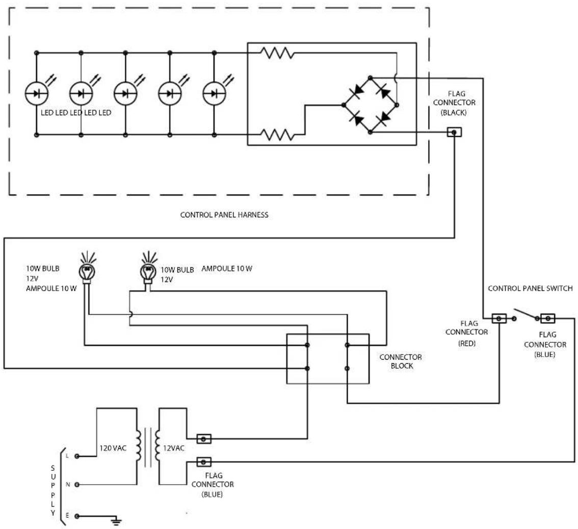
Napoleon products are protected by one or more U.S. and Canadian and/or foreign patents or patents pending.

N415-0220CE-GB-DE
- DANGER
- WARNING
- THANK YOU FOR CHOOSING NAPOLEON
- Napoleon Gas Grill President's Limited Lifetime Warranty
- Conditions and Limitations
- WARNING! Failure to follow these instructions could result in property damage, personal injury or death. Read and follow all warnings and instructions in this manual prior to operating grill.
- Safe Operating Practices
- Electrical Precautions
- WARNING! Failure to follow these instructions could result in property damage, personal injury or death.
- Correct Disposal Of This Product
- Gas Cylinder
- WARNING! Ensure that the hose is routed to maintain proper clearance to the underside of the unit. Hoses that contact high temperature surfaces may melt and leak, causing a fire.
- WARNING!
- Gas Hose
- Technical Data
- Leak Testing Instructions
- Lighting Instructions
- Operating The Grill
- Infrared Heat
- Maintenance / Cleaning Instructions
- WARNING! Accumulated grease is a fire hazard.
- WARNING! Hose: Check for abrasions, melting, cuts, and cracks in the hose. If any of these conditions exist, do not use the gas grill. Have the part replaced by your Napoleon Grill dealer or qualified gas installer.
- CAUTION! Beware of Spiders.
- WARNING! When reinstalling the burner after cleaning it is very important that the valve/orifice enters the burner tube before lighting your gas grill. If the valve is not inside the burner tube a fire or explosion could occur.
- KEEP YOUR RECEIPT AS PROOF OF PURCHASE TO VALIDATE YOUR WARRANTY.
- Ordering Replacement Parts
- Warranty Information
- (Record information here for easy reference)
- GEFAHR
- Getting Started
- TOOLS REQUIRED FOR ASSEMBLY (tools not included)
- LE485RSIB MODEL
- LE485RSIB MODELLEN
- Rotisserie Kit Assembly Instruction
- Providing Power To The Internal Lights
- (485RSIB MODEL ONLY)
- WARNING - FIRE HAZARD
- Natural Gas Only – Proper Hose Connection
- (FOR MODELS WITH INTERNAL LIGHTS ONLY)
Brand : Napoleon
Model : LE485SB
Category : Grill