K4453 - Label printer Kroy - Free user manual and instructions
Find the device manual for free K4453 Kroy in PDF.


User questions about K4453 Kroy
0 question about this device. Answer the ones you know or ask your own.
Ask a new question about this device
Download the instructions for your Label printer in PDF format for free! Find your manual K4453 - Kroy and take your electronic device back in hand. On this page are published all the documents necessary for the use of your device. K4453 by Kroy.
USER MANUAL K4453 Kroy
THERMAL TRANSFER / DIRECT THERMAL BAR CODE PRINTER
USER'S
MANUAL
Contents
- Introduction......1
- Getting Started....1
2.1 Unpacking and Inspection .... 1
2.2 Equipment Checklist....1
2.3 Printer Parts....3
- Setup....4
3.1 Setting Up the Printer ....4
3.2 Loading the Ribbon....4
3.3 Loading Label Stock 6
3.4 External Label Roll Mount Installation (Option) 8
3.5 Peel-off Module Installation (Option) 10
3.5.1 Loading the Paper in Peel-off Mode 13
3.6 Cutter Module Installation (Option) 15
3.6.1 Loading Label in Cutter Mode 17
3.7 Instructions to Top Cover Operation 18
3.8 Diagnostic Tool 21
3.8.1 Start the Diagnostic Tool 21
3.8.2 Printer Function (Calibrate sensor, Ethernet setup, RTC setup.....) 22
3.9 Setting Ethernet by Diagnostic Utility (Option) 23
3.9.1 Using USB interface to setup Ethernet interface 23
3.9.2 Using RS-232 interface to setup Ethernet interface ..... 24
3.9.3 Using Ethernet interface to setup Ethernet interface ..... 25
3.10 Install Memory Card 27
- Power on Utilities....29
4.1 Ribbon and Gap/Black Mark Sensor Calibration 29
4.2 Gap/Black Mark Calibration ; Self-test ; Dump Mode ...... 30
4.3 Printer Initialization....33
4.4 Black Mark Sensor Calibration ...... 34
4.5 Gap Sensor Calibration 34
4.6 Skip AUTO.BAS....34
- Maintenance....36
5.1 Cleaning....36
- Troubleshooting....38
6.1 LED Status....38
6.2 Print Quality....39
- LED and Button Operation 41
7.1 LED....41
7.2 Button Operation....41
1. Introduction
Thank you for purchasing the KROY K4452/4453 series of Thermal Transfer and Direct Thermal Bar Code Printers. Although the printer takes only a small amount of space, it delivers reliable, superior performance.
This printer provides both thermal transfer and direct thermal printing at user selectable speed of: 2.0, 3.0, 4.0 or 5.0 ips for KROY K4452; 2.0 or 3.0 ips for KROY K4453. It accepts roll feed, die-cut, and fan-fold labels for both thermal transfer and direct thermal printing. All common bar codes formats are available. Fonts and bar codes can be printed in 4 directions, 8 different alphanumeric bitmap fonts and a build-in true type font capability. You will enjoy high throughput for printing labels with this printer.
CAUTION
- HAZARDOUS MOVING PARTS IN CUTTER MODULE. KEEP FINGER AND OTHER BODY PARTS AWAY.
- THE MAIN BOARD INCLUDES REAL TIME CLOCK FEATURE HAS LITHIUM BATTERY CR2032 INSTALLED. RISK OF EXPLOSION IF BATTERY IS REPLACED BY AN INCORRECT TYPE.
- DISPOSE OF USED BATTERIES ACCORDING TO THE MANUFACTURER INSTRUCTIONS.
B 급기기
(가정용 정보통신기기)
2.1 Unpacking and Inspection
This printer has been specially packaged to withstand damage during shipping. Please carefully inspect the packaging and printer upon receiving the bar code printer. Please retain the packaging materials in case you need to reship the printer.
2.2 Equipment Checklist
Printer
■ BarTender UltraLite CD disk
■ Quick start guide
■ USB port cable
■ External universal switching power supply
■ Power Cord
■ Label Spindle, fixing tab x2, 1.5" core adapter x2
■ Ribbon spindle x2
■ Ribbon rewind spindle paper core
If any parts are missing, please contact the Customer Service Department of your purchased reseller or distributor.
Dealer option
■ Peel off module assembly.
■ Guillotine cutter
Full cut:
Paper thickness: 0.06\~ 0.19mm, 500,000 cuts
Partial cut:
Paper thickness: 0.06\~0.12mm, 500,000 cuts Paper thickness: 0.19mm 200,000 cuts
■ Main board integrated with internal Ethernet
■ Internal Ethernet print server module
User option
KP-200
■ KU-007 plus
■ External Ethernet print server
■ External wireless (802.11b/g) print server
■ External roll mount, media OD. 214 mm (8.4") with 3" core label spindle
■ Contact CCD contact scanner
■ Long range linear image bar code scanner
2.3 Printer Parts
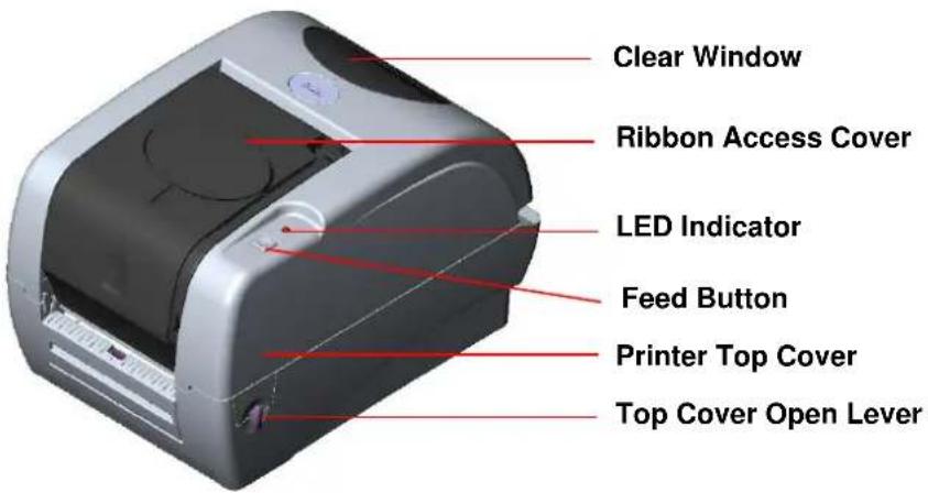
text_image
Clear Window Ribbon Access Cover LED Indicator Feed Button Printer Top Cover Top Cover Open LeverFig. 1 Top front view
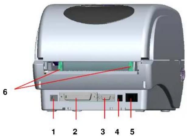
text_image
6 1 2 3 4 5- USB Interface
- Centronics Interface
- RS-232C DB-9 Interface
- Power Jack
- Power Switch
- Rear Paper Guide
Fig. 2 Rear view
Note:
The interface picture here is for reference only. Please refer to the product specification for the interfaces availability.
3. Setup
3.1 Setting Up the Printer
- Place the printer on a flat, secure surface.
- Make sure the power switch is off.
- Connect the printer to the computer with the Centronics or USB cable.
- Plug the power cord into the power supply connector at the rear of the printer, and then plug the power cord into a properly grounded receptacle.
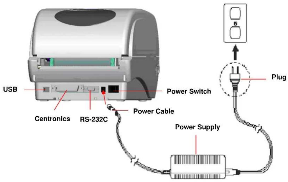
text_image
USB Centronics RS-232C Power Switch Power Cable Plug Power SupplyFig. 3 Attach power supply to printer
Note:
Please switch OFF printer power switch prior to plug in the power cord to printer power jack.
3.2 Loading the Ribbon
The printer will detect if the ribbon is installed after turning on power on and it will set printing mode to thermal transfer or direct thermal printing mode. If printer does not detect the ribbon, the ribbon take up motor will be turned off.
Make sure both the ribbon access window and the printer top cover are closed prior to powering up the printer.
Please follow the steps below to install the ribbon into printer.
- Push down on the ribbon access window to unlatch and open the cover.
- Place a paper core onto the ribbon rewind spindle.
- Mount the ribbon rewind paper core on the front hubs.
- Install a ribbon on the ribbon supply spindle.
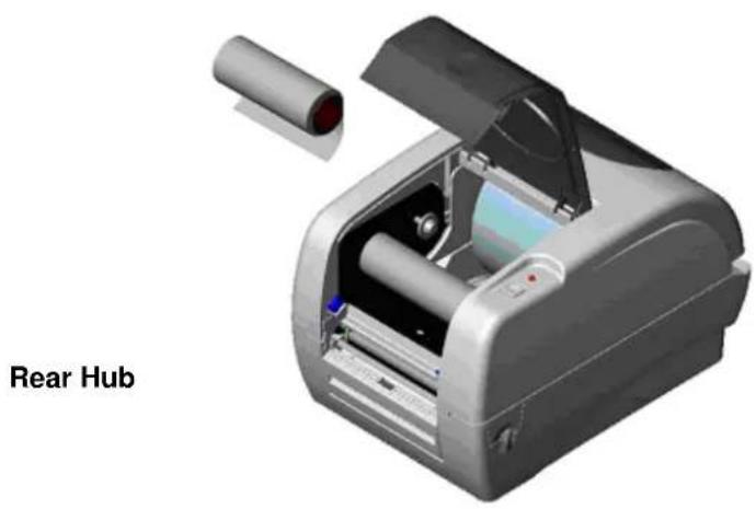
- Mount the ribbon supply spindle on the rear hubs.
- Thread the ribbon leading tape downward pass the print head.
- Attach the ribbon leader to the ribbon rewind paper core.
- Rotate the ribbon rewind paper core until the ribbon leader is thoroughly, firmly encompassed by the black section of the ribbon.
- Close the ribbon access window.
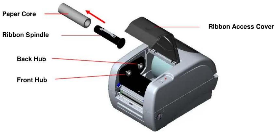
text_image
Paper Core Ribbon Spindle Back Hub Front Hub Ribbon Access CoverFig. 4 Ribbon installation (I)
natural_image
3D rendering of a rear hub scanner with open lid and internal components (no text or symbols on device)Fig. 5 Ribbon installation (II)
3.3 Loading Label Stock
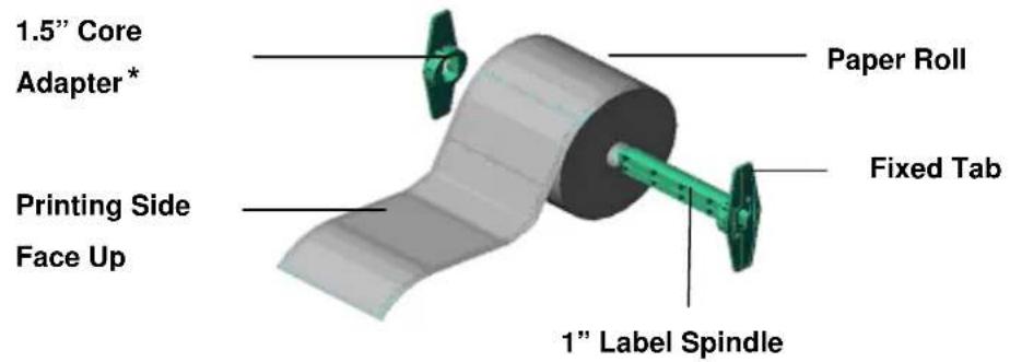
- Insert a 1" label spindle into a paper roll (* If your paper core is 1 inch, remove the 1.5" core adapter from the fixed tab. If label width is 4 inch wide, two fixing tabs are not required.).
text_image
1.5" Core Adapter* Printing Side Face Up Paper Roll Fixed Tab 1" Label SpindleFig. 6 Label roll installation (I)
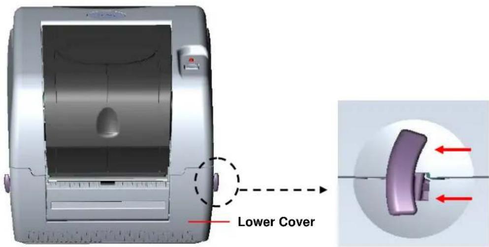
- Open the printer's top cover by releasing the green top cover open levers located on each side of the printer and lifting the top cover. A top cover support at the rear of the printer will hold the printer top cover open.
text_image
Lower CoverFig. 7 Pull the lever to open the cover
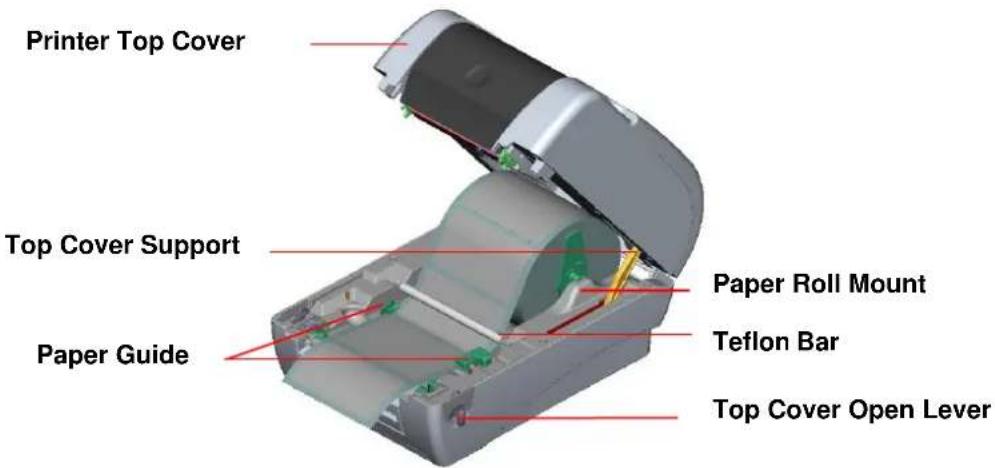
- Place a roll of paper onto the center of the paper roll mount.
- Feed the paper, printing side face up, through the Teflon bar and the paper guide and pass over the platen.
- Adjust the green center-biased paper guides to slightly touch the edges of the label backing.
- To close the printer top cover, lift the cover to the ultimate open angle then use both hands to close the cover gently. Close the printer top cover slowly and make sure the cover latches securely.
Note:
- Make sure hands are not placed between printer top cover and lower cover when close the top cover.
- Do not free fall the top cover.
- Failure to securely close and lock the cover will result in poor print quality.
text_image
Printer Top Cover Top Cover Support Paper Guide Paper Roll Mount Teflon Bar Top Cover Open LeverFig. 8 Label installation (II)
3.4 External Label Roll Mount Installation (Option)
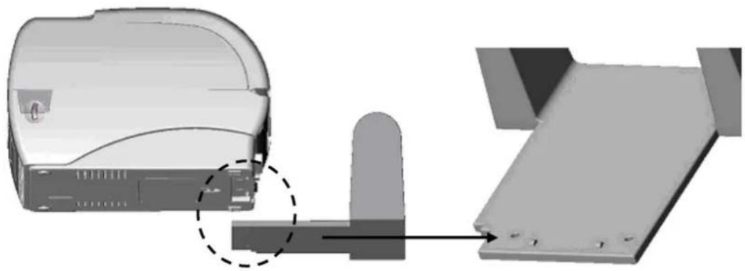
- Attach an external paper roll mount on the bottom of the printer.
natural_image
3D mechanical assembly diagram showing a component with a dashed circular annotation and a separate view of a metal bracket (no text or symbols)Fig. 9 Attach the external roll mount to the printer
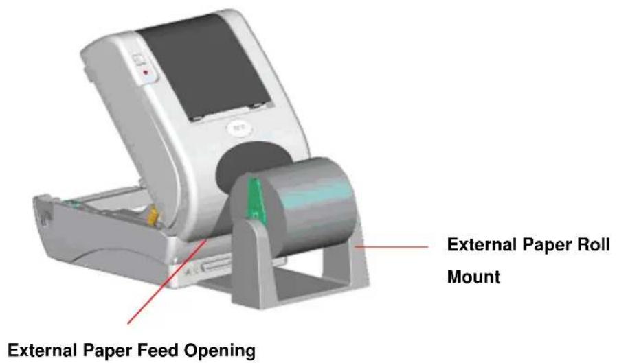
- Open the printer top cover by releasing the top cover open levers. The top cover support will hold the printer top cover.
- Install a roll of paper on the external paper roll mount.
- Feed the paper to the external paper feed opening through the rear paper guide.
text_image
External Paper Roll Mount External Paper Feed OpeningFig. 10 External roll mount label installation (I)
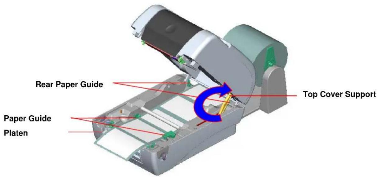
- Feed the paper, printing side face up, through the paper guide and pass over the platen.
- Adjust the paper guides to fit the paper width.
- Close the printer top cover by lifting the top cover to the maximum opening angle then push down the top cover gently.
text_image
Rear Paper Guide Top Cover Support Paper Guide PlatenFig. 11 External roll mount label installation (II)
3.5 Peel-off Module Installation (Option)
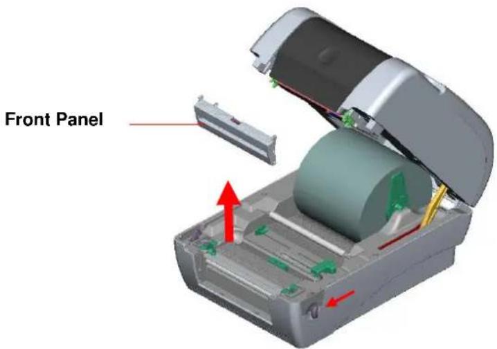
- Open the top cover and remove the front panel from the printer.
text_image
Front PanelFig. 12 Remove the front panel
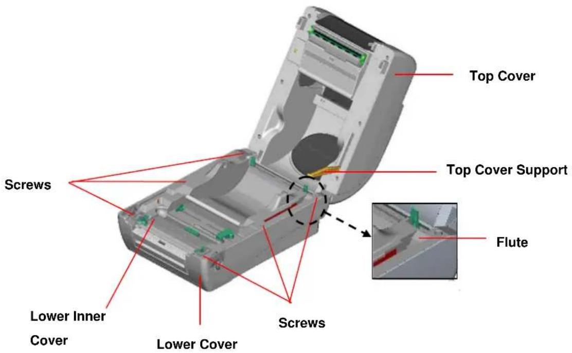
- Open the top cover and hold it and push down and push backward the top cover support then push backward the top cover.
- Use a screwdriver to screw off 6 screws on the lower inner cover.
text_image
Top Cover Screws Top Cover Support Flute Lower Inner Cover Lower Cover ScrewsFig. 13 Remove 6 screws from lower inner cover
- Upside down the printer. Remove two screws at the hinge and remove one screw at
memory card cover.
-
Hold the lower cover to lift up the top cover open levers to separate the lower inner cover and the lower cover.
-
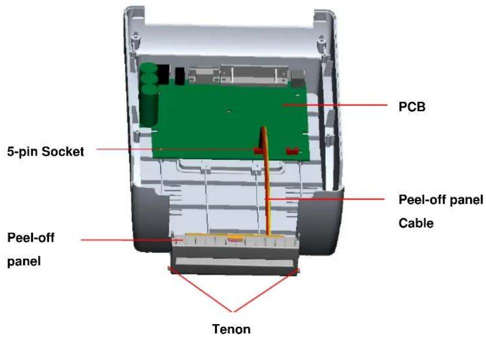
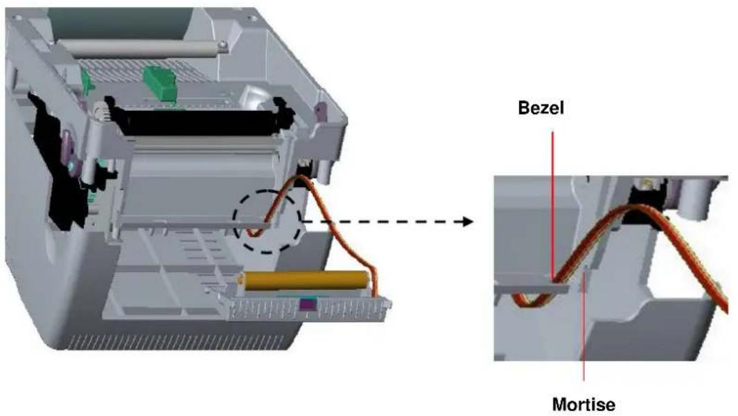
Arrange the cable through the bezel. Connect the peel-off panel cable to the 5-pin socket on printer PCB.
text_image
PCB 5-pin Socket Peel-off panel Cable Peel-off panel TenonFig. 14 Connect peel-off sensor cable to main board
text_image
Bezel MortiseFig. 15 Peel-off sensor cable installation
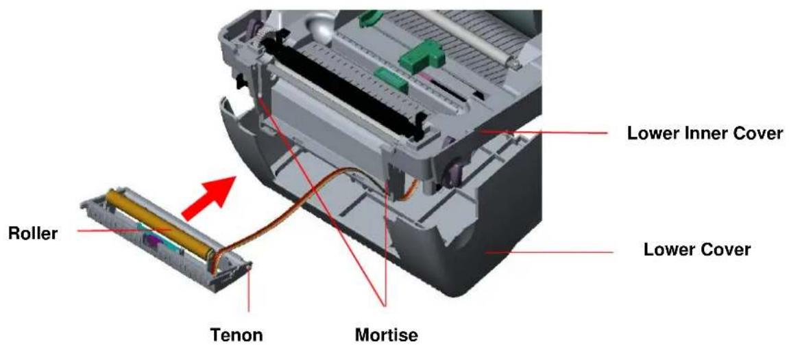
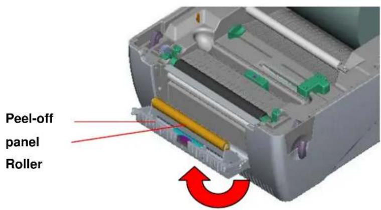
- Insert the peel-off tenons into the lower inner cover mortises until tenons snap into places.
text_image
Lower Inner Cover Lower Cover Roller Tenon MortiseFig. 16 Peel-off panel installation (I)
- Arrange the lower inner cover back to the lower cover.
text_image
Peel-off panel RollerFig. 17 Peel-off panel installation (II)
-
Lift up the peel-off panel to the lower cover to close it.
-
Use a screwdriver to screw down whole screws on the lower inner cover and the lower cover.
-
Close the top cover by arranging the top cover support back to the flute and push it forward then close the top cover slowly.
3.5.1 Loading the Paper in Peel-off Mode
Note: Both thermal paper and plain paper apply for peel-off function but neither PVC nor vynle work at peel-off function.
- Insert a 1" label spindle into a paper roll.
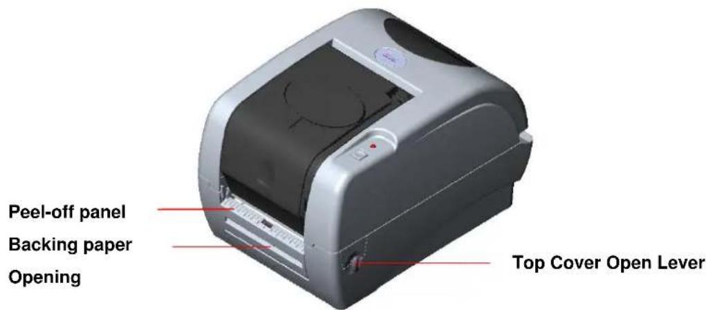
- Open the printer top cover by pulling the top cover open levers. The top cover support will hold the printer top cover.
text_image
Peel-off panel Backing paper Opening Top Cover Open LeverFig. 18 Open the top cover
- Install the paper roll on the paper roll mount.
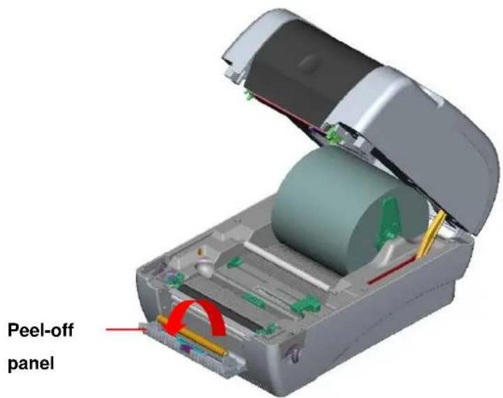
- Open the peel-off panel by pulling it out.
text_image
Peel-off panelFig. 19 Open the peel-off panel
- Feed the paper, printing side facing up, through the paper guide and pass over the platen.
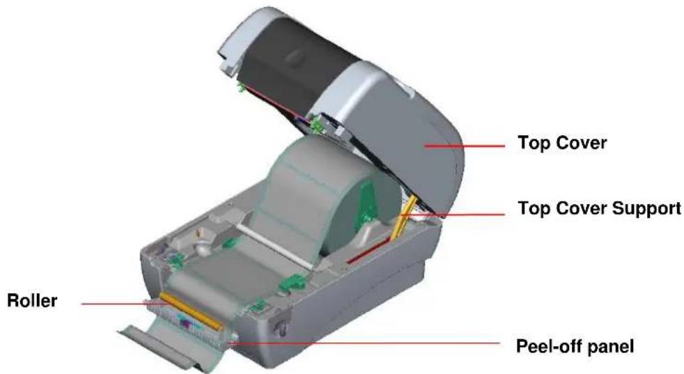
- Lead the paper through the backing paper opening, beneath the roller, pull the
- Adjust the paper guide by removing left or right to fit the paper width.
text_image
Top Cover Top Cover Support Roller Peel-off panelFig. 20 Lead the paper through the backing paper opening, beneath the roller
- Push the peel-off panel back to the printer.
- Close the top cover by lifting up the top cover support and close the top cover slowly. Note: Pull the label outward tightly after closing the top cover.
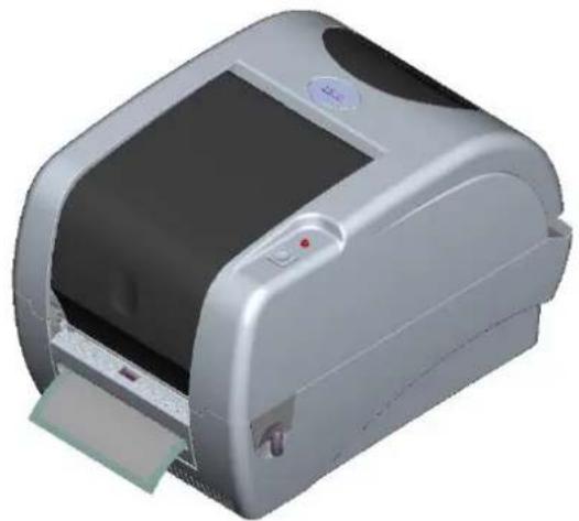
natural_image
3D rendering of a silver printer with a paper clip and control panel (no visible text or symbols)Fig. 21 Complete label installation for peel-off mode
3.6 Cutter Module Installation (Option)
- Pull the top cover open levers to open the top cover.
- Remove the front panel from the lower cover.
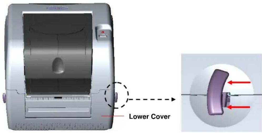
text_image
Lower CoverFig. 22 Pull the lever to open the cover
- Open the top cover and hold it and push down and push backward the top cover support then push backward the top cover.
- Use a screwdriver to screw off 6 screws on the lower inner cover.
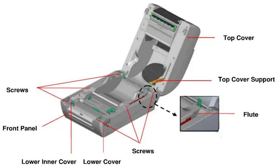
text_image
Top Cover Top Cover Support Screws Front Panel Lower Inner Cover Lower Cover Screws FluteFig. 23 Remove 6 screws from lower inner cover
- Place the printer upside down and unscrew the two screws of the hinge holder on the lower cover.
- Unscrew the screw of the memory card cover and remove the memory card cover. Plug in the cutter driver IC at U30 (KROY K4452/4453 series) socket on the main board.
- Use both thumbs to hold the lower cover and index fingers to lift up the top cover open levers to separate the lower inner cover and the lower cover.
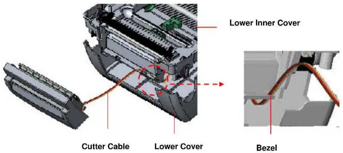
- Arrange the cable through the bezel. Connect the cutter module cable to the 4-pin socket on printer PCB.
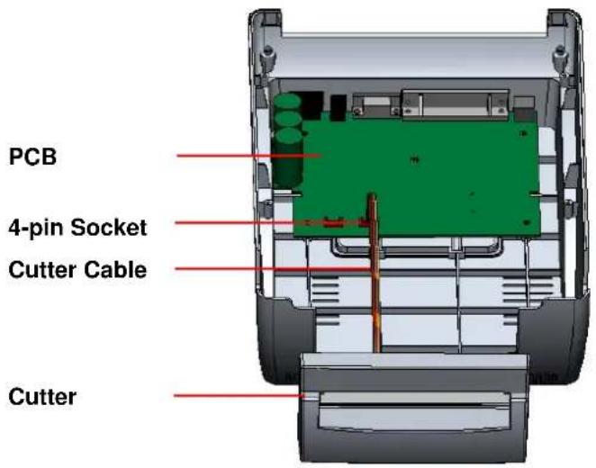
text_image
PCB 4-pin Socket Cutter Cable CutterFig. 24 Cutter module installation
text_image
Lower Inner Cover Cutter Cable Lower Cover BezelFig. 25 Cutter module cable arrangement
-
Arrange the lower inner cover back to the lower cover.
-
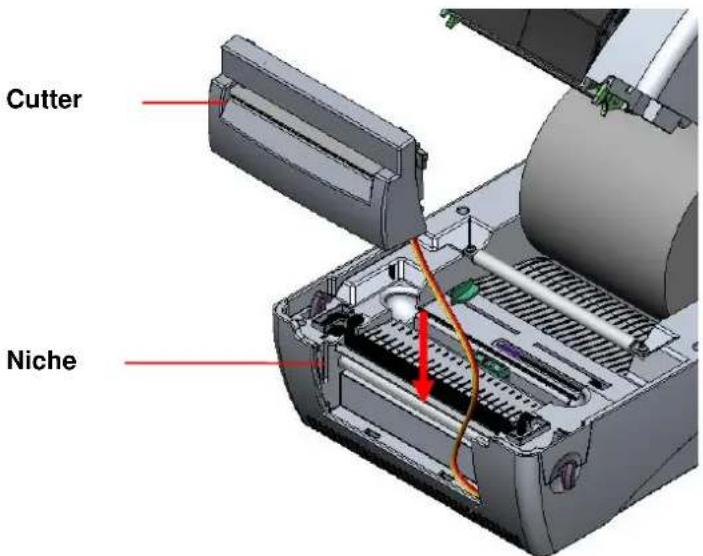
Install the cutter into the niches of the printer.
text_image
Cutter NicheFig. 26 Cutter module installation
- Use a screwdriver to screw whole screws on the lower inner cover and the lower cover.
- Close the top cover by arranging the top cover support back to the flute and push it forward then close the top cover slowly.
3.6.1 Loading Label in Cutter Mode
- Insert a 1" label spindle into a paper roll.
- Open the printer top.
- Install a paper roll on the paper roll mount.
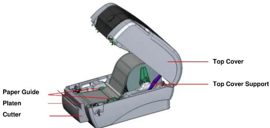
- Feed the paper, printing side face up, through the paper guide and pass over the platen.
- Lead the paper through the cutter paper opening.
- Adjust the paper guide by removing left or right to fit the paper width.
text_image
Top Cover Top Cover Support Paper Guide Platen CutterFig. 27 Label installation in cutter mode
- Close the top cover by lifting up the top cover support and close the top cover slowly.
natural_image
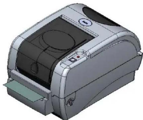
3D CAD model of a printer with visible ports and control panel (no text or symbols)Fig. 28 Complete label installation in cutter mode
3.7 Instructions to Top Cover Operation
Please take care when opening or closing the printer's top cover by carefully following these instructions.
To Open:
-
When facing the front of the printer pull the cover release levers on both sides of printer towards you.
-
Lift up the top gradually.
There are two stop positions for the top cover. Position 1 and 2 are indicated on the label below.
Note: To hold the cover open at position 1, you must lift the cover higher than the stopping point at position 1 and gently lower the cover to stopping point 1. Do not let the cover free fall!
- Fully open the top cover and gently lower it to stop position 2.
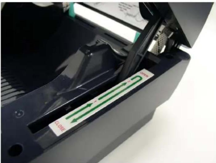
text_image
12.005 31.005Fig. 1 Top cover support is fixed at position 2
- To close the cover, lift up the top cover to the ultimate angle then close the top cover gently and it will be kept at a stop position between 1 and 2 for a while. Use both hands to gently push down the top cover to close it and make sure the cover is latched on both sides.
Note: Do not place your hands between top cover and lower cover when closing the top cover!
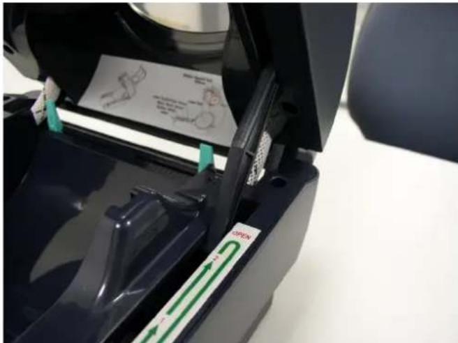
text_image
Close-up of a printer's paper feeding mechanism with green directional arrows and handwritten notes, showing text labels like 'OPEN' and 'EXIT'.Fig. 2 Top cover is fully open and ready to close
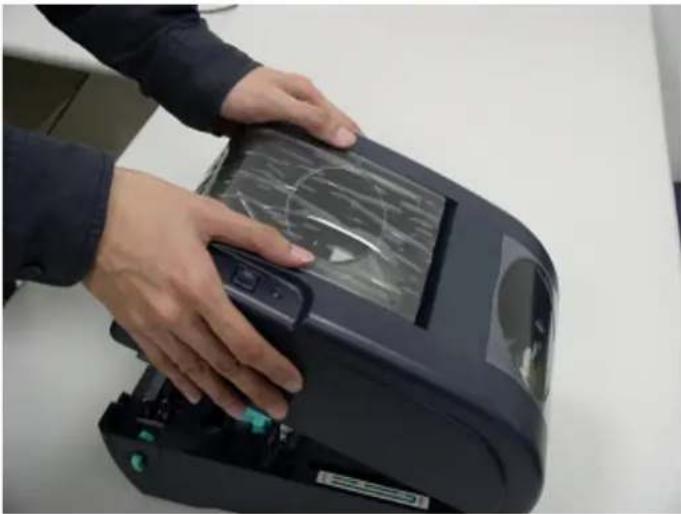
natural_image
Person adjusting a fingerprint scanner device on a white surface (no visible text or symbols)Fig. 3 Use both hands to close the top cover
- Do not force the cover! If you are not sure if top cover is fixed at stop position, please do not push top cover to close it or the top cover will be damaged. Please open the top cover to the ultimate angle to close the top cover again. Use both hands to push top cover to close it.
3.8 Diagnostic Tool
The Diagnostic Utility is a toolbox that allows users to explore the printer's settings and status; change printer settings; download graphics, fonts, and firmware; create printer bitmap fonts; and to send additional commands to the printer. Using this convenient tool, you can explore the printer status and settings and troubleshoot the printer.
Note: This utility works with printer firmware V6.00 and later versions.
3.8.1 Start the Diagnostic Tool
- Double click on the Diagnostic tool icon to start the software.
- There are four features (Printer Configuration, File Manager, Bitmap Font Manager, Command Tool) included in the Diagnostic utility.
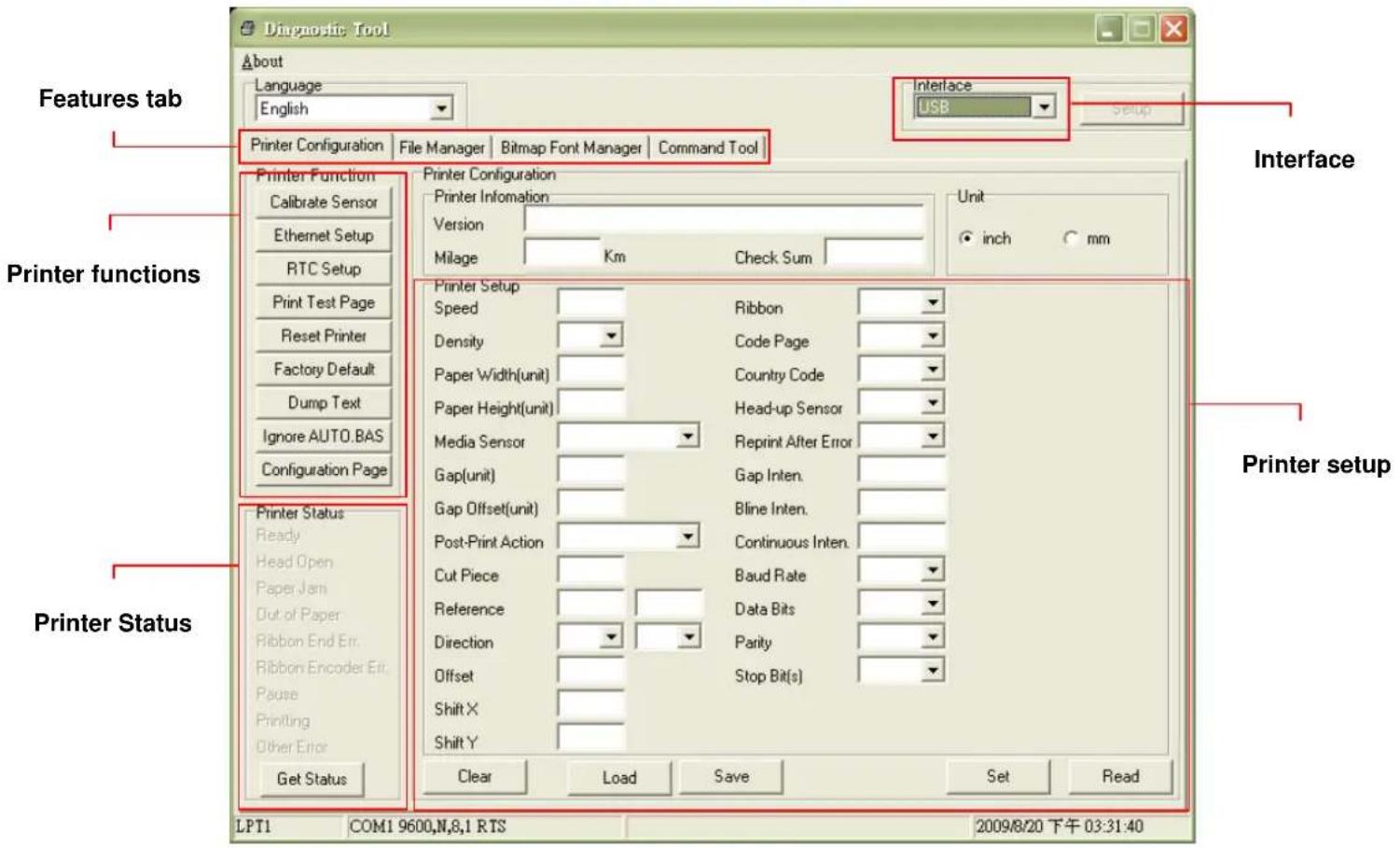
text_image
Diagnostic Tool About Language English Interface USB Printer Configuration File Manager Bitmap Font Manager Command Tool Printer Function Calibrate Sensor Ethernet Setup RTC Setup Print Test Page Reset Printer Factory Default Dump Text Ignore AUTO.BAS Configuration Page Printer Configuration Printer Information Version Milage Km Check Sum Unit inch mm Printer Setup Speed Ribbon Density Code Page Paper Width(unit) Country Code Paper Height(unit) Head-up Sensor Media Sensor Reprint After Error Gap(unit) Gap Inten. Gap Offset(unit) Bline Inten. Post-Print Action Continuous Inten. Cut Piece Baud Rate Reference Data Bits Direction Parity Offset Stop Bit(s) Shift X Shift Y Get Status Clear Load Save Set Read Printer status Printer setup LPT1 COM1 9600,N,8,1 RTS 2009/8/20 下午 03:31:403.8.2 Printer Function (Calibrate sensor, Ethernet setup, RTC setup.....)
- Select the PC interface connected with bar code printer.
- Click the "Function" button to setting.
- The detail functions in the Printer Function Group are listed as below.
| Printer FunctionCalibrate SensorEthernet SetupRTC SetupPrint Test PageReset PrinterFactory DefaultDump TextIgnore AUTO.BASConfiguration Page | Function Description | |
| Calibrate Sensor | Calibrate the sensor specified in the Printer Setup group media sensor field | |
| Ethernet Setup | Setup the IP address, subnet mask, gateway for the on board Ethernet (Please refer to next section) | |
| RTC Time Synchronize printer Real Time Clock with PC | ||
| Print Test Page Print a test page | ||
| Reset Printer Reboot printer | ||
| Factory Default | Initialize the printer and restore the settings to factory default. | |
| Dump Text To activate the printer dump mode. | ||
| Ignore AUTO.BAS Ignore the downloaded AUTO.BAS program | ||
| Configuration Page | Print printer configuration | |
Note:
For more information about Diagnostic Tool, please refer to the diagnostic utility quick start guide in the CD disk \ Utilities directory.
3.9 Setting Ethernet by Diagnostic Utility (Option)
The Diagnostic Utility is enclosed in the CD disk \Utilities directory. Users can use Diagnostic Tool to setup the Ethernet by RS-232, USB and Ethernet interfaces. The following contents will instruct users how to configure the Ethernet by these three interfaces.
3.9.1 Using USB interface to setup Ethernet interface
- Connect the USB cable between the computer and the printer.
- Turn on the printer power.
- Start the Diagnostic Utility by double clicking on the DiagTool.exe icon. Note: This utility works with printer firmware V6.00 and later versions.
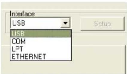
- The Diagnostic Utility default interface setting is USB interface. If USB interface is connected with printer, no other settings need to be changed in the interface field.
text_image
Interface USB USB COM LPT ETHERNET- Click on the "Ethernet Setup" button from "Printer Function" group in Printer Configuration tab to setup the IP address, subnet mask and gateway for the on board Ethernet.

text_image
Printer Function Calibrate Sensor Ethernet Setup RTC Setup Print Test Page Reset Printer Factory Default Dump Text Ignore AUTO.BAS Configuration Page Ethernet Setup IP Setup DHCP Static IP IP 255.255.255.255 Subnet Mask 255.255.255.255 Gateway 255.255.255.255 Printer Name PS-FF04E2 MAC Address 00-1B-82-FF-04-E2 Set Printer Name Set IP Cancel3.9.2 Using RS-232 interface to setup Ethernet interface
- Connect the computer and the printer with a RS-232 cable.
- Turn on the printer power.
- Start the Diagnostic Utility by double clicks on the DiagTool.exe icon.
Note: This utility works with printer firmware V6.00 and later versions.
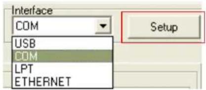
- Select "COM" as interface then click on the "Setup" button to setup the serial port baud rate, parity check, data bits, stop bit and flow control parameters.
text_image
Interface COM USB COM LPT ETHERNET Setup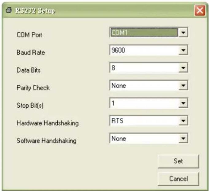
text_image
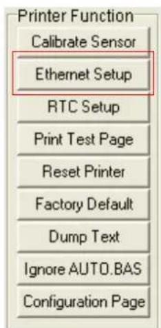
RS232 Setup COM Port COM1 Baud Rate 9600 Data Bits 8 Parity Check None Stop Bit(s) 1 Hardware Handshaking RTS Software Handshaking None Set Cancel- Click on the "Ethernet Setup" button from printer function of Printer Configuration tab to setup the IP address, subnet mask and the gateway for the on board Ethernet.
text_image
Printer Function Calibrate Sensor Ethernet Setup RTC Setup Print Test Page Reset Printer Factory Default Dump Text Ignore AUTO.BAS Configuration Page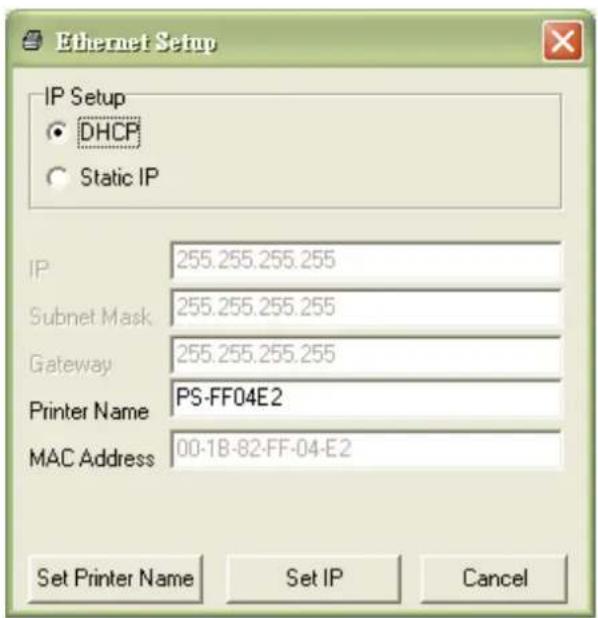
text_image
Ethernet Setup IP Setup ● DHCP ○ Static IP IP 255.255.255.255 Subnet Mask 255.255.255.255 Gateway 255.255.255.255 Printer Name PS-FF04E2 MAC Address 00-1B-82-FF-04-E2 Set Printer Name Set IP Cancel3.9.3 Using Ethernet interface to setup Ethernet interface
-
Connect the computer and the printer to the LAN.
-
Turn on the printer power.
-
Start the Diagnostic Utility by double clicks on the DiagTool.exe icon. Note: This utility works with printer firmware V6.00 and later versions
-
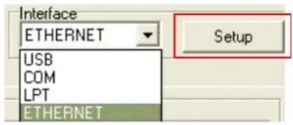
Select "Ethernet" as the interface then click on the "Setup" button to setup the IP address, subnet mask and gateway for the on board Ethernet.
text_image
Interface ETHERNET USB COM LPT ETHERNET Setup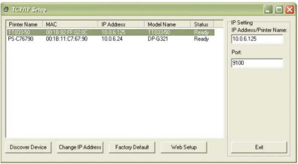
text_image
TCP/IP Setup Printer Name MAC IP Address Model Name Status TT033-50 00:1B:82:FF:02:0C 10.0.6.125 TT033-50 Ready PS-C76790 00:1B:11:C7:67:90 10.0.6.24 DP-G321 Ready IP Setting IP Address/Printer Name: 10.0.6.125 Port: 9100 Discover Device Change IP Address Factory Default Web Setup Exit- Click the "Discover Device" button to explore the printers that exist on the network.
- Select the printer in the left side of listed printers, the correspondent IP address will be shown in the right side "IP address/Printer Name" field.
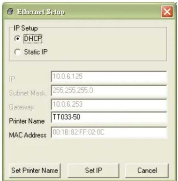
- Click "Change IP Address" to configure the IP address obtained by DHCP or static.
text_image
Ethernet Setup IP Setup ● DHCP ○ Static IP IP 10.0.6.125 Subnet Mask 255.255.255.0 Gateway 10.0.6.253 Printer Name TT033-50 MAC Address 00:1B:82:FF:02:0C Set Printer Name Set IP CancelThe default IP address is obtained by DHCP. To change the setting to static IP address, click “Static IP” radio button then enter the IP address, subnet mask and gateway. Click “Set IP” to take effect the settings.
Users can also change the “Printer Name” by another model name in this fields then click “Set Printer Name” to take effect this change.
Note: After clicking the "Set Printer Name" or "Set IP" button, printer will reset to take effect the settings.
- Click "Exit" button to exit the Ethernet interface setup and go back to Diagnostic Tool main screen.
Factory Default button
This function will reset the IP, subnet mask, gateway parameters obtained by DHCP and reset the printer name.
Web setup button
Except to use the Diagnostic Utility to setup the printer, you can also explore and configure the printer settings and status or update the firmware with the IE or Firefox web browser. This feature provides a user friendly setup interface and the capability to manage the printer remotely over a network.
3.10 Install Memory Card
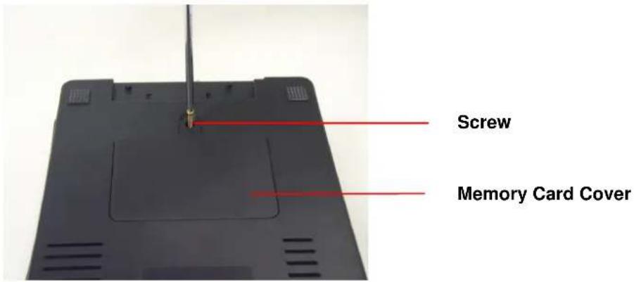
- Turn the printer upside down.
- Remove the screw that fixes the memory card cover.
text_image
Screw Memory Card Cover- Plug in the memory card on main board.
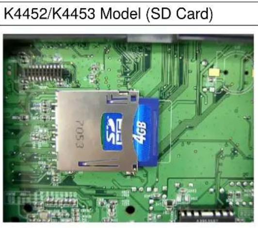
text_image
K4452/K4453 Model (SD Card)- Revert the memory card cover.
* Recommended SD card specification.
| SD card spec SD | card capacity | Approved SD card manufacturer |
| V1.0, V1.1 128 MB SanDisk, Transcend | ||
| V1.0, V1.1 256 MB SanDisk, Transcend, Panasonic | ||
| V1.0, V1.1 512 MB SanDisk, Transcend, Panasonic | ||
| V1.0, V1.1 1 GB SanDisk, Transcend, Panasonic | ||
| V2.0 SDHC CLASS 4 | 4 GB | |
| V2.0 SDHC CLASS 6 | 4 GB SanDisk, Transcend, Panasonic | |
| V1.0, V1.1 microSD 128 MB Transcend, Panasonic | ||
| V1.0, V1.1 microSD 256 MB Transcend, Panasonic | ||
| V1.0, V1.1 microSD 512 MB Panasonic |
| V1.0, V1.1 microSD 1 | GB Transcend, Panasonic |
| V2.0 SDHC CLASS 4 | microSD 4 GB Panasonic |
| V2.0 SDHC CLASS 6 | microSD 4 GB Transcend |
| V1.0, V1.1 miniSD 128 | MB Transcend, Panasonic |
| V1.0, V1.1 miniSD 256 | MB Transcend, Panasonic |
| V1.0, V1.1 miniSD 512 | MB Transcend, Panasonic |
| V1.0, V1.1 miniSD 1 GB | Transcend, Panasonic |
| V2.0 SDHC CLASS 4 | miniSD 4 GB Transcend |
| V2.0 SDHC CLASS 6 | miniSD 4 GB |
| - The DOS FAT file system is supported for the SD card.- Folders/files stored in the SD card should be in the 8.3 filename format- The miniSD/microSD card to SD card slot adapter is required. | |
4. Power on Utilities
There are six power-on utilities to set up and test printer hardware. These utilities are activated by pressing FEED button and by turning on the printer power simultaneously.
The utilities are listed as below:
- Ribbon sensor calibration ; Gap/black mark sensor calibration
- Gap/black mark sensor calibration ; Self-test and dump mode
- Printer initialization
- Black mark sensor calibration
- Gap sensor calibration
- Skip AUTO.BAS
4.1 Ribbon and Gap/Black Mark Sensor Calibration
Gap/black mark sensor sensitivity should be calibrated at the following conditions:
- A brand new printer
- Change label stock.
- Printer initialization.
Please follow the steps below to calibrate the ribbon and gap/black mark sensor.
- Turn off the power switch.
- Hold on the button then turn on the power switch.
3 Release the button when LED becomes red and blinking. (Any red will do during the 5 blinks).
■ It will calibrate the ribbon sensor and gap/black mark sensor sensitivity.
■ The LED color will be changed as following order :
Amber → red (5 blinks) → amber (5 blinks) → green (5 blinks) → green/amber (5 blinks) → red/amber (5 blinks) → solid green
Note:
Please select gap or black mark sensor by GAP or BLINE command prior to calibrate the sensor.
For more information about GAP and BLINE command, please refer to TSPL2 programming manual.
4.2 Gap/Black Mark Calibration ; Self-test ; Dump Mode
While calibrate the gap/black mark sensor, printer will measure the label length, print the internal configuration (self-test) and then enter the dump mode. To calibrate gap or black mark sensor, depends on the sensor setting in the last print job.
Please follow the steps below to calibrate the sensor.
- Turn off the power switch.
- Hold on the button then turn on the power switch.
- Release the button when LED becomes amber and blinking. (Any amber will do during the 5 blinks).
■ The LED color will be changed as following order.
Amber → red (5 blinks) → amber (5 blinks) → green (5 blinks) → green/amber (5 blinks) → red/amber (5 blinks) → solid green
- It calibrates the sensor and measures the label length and prints internal settings then enter the dump mode.
Note:
Please select gap or black mark sensor by Diagnostic Tool or by GAP or BLINE command prior to calibrate the sensor.
For more information about GAP and BLINE command, please refer to TSPL2 programming manual.
Self-test
Printer will print the printer configuration after gap/black mark sensor calibration. Self-test printout can be used to check if there is any dot damage on the heater element, printer configurations and available memory space.
| Self-test printout | |
| PRINTER INFO.XXXXXXXX Version: X.XXMILAGE(m): 0CHECKSUM: XXXXXXXXSERIAL PORT: 9600,N,8,1CODE PAGE: 850COUNTRY CODE: 001SPEED: X INCHDENSITY: 8SIZE: 4.00 , 4.00GAP: 0.12 , 0.00TRANSPARENCE: XX**********FILE LIST:DRAM FILE: 0 FILE(S)FLASH FILE: 0 FILE(S)PHYSICAL DRAM: XXXX KBYTESAVAILABLE DRAM: XXXX KBYTES FREEPHYSICAL FLASH: XXXX KBYTESAVAILABLE FLASH: XXXX KBYTES FREEEND OF FILE LIST********** | Print head check patternModel name and F/W versionPrinted mileage (meter)Firmware checksumSerial port configurationCode pageCountry codePrint speed (inch/sec)Print darknessLabel size (inch)Gap distance (inch)Gap/black mark sensor sensitivityNumbers of download filesTotal & available memory space |
Dump mode
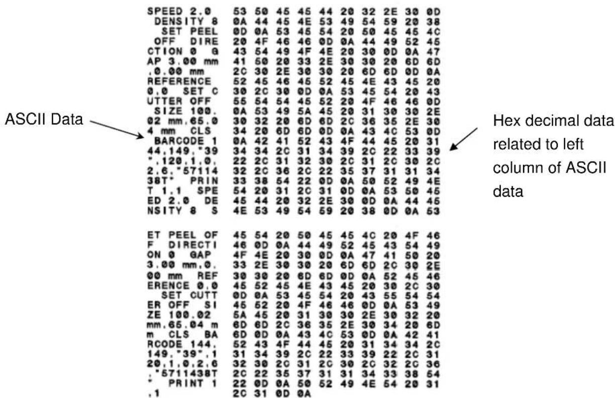
Printer will enter dump mode after printing printer configuration. In the dump mode, all characters will be printed in 2 columns as following. The left side characters are received from your system and right side data are the corresponding hexadecimal value of the characters. It allows users or engineers to verify and debug the program.
text_image
ASCII Data SPEED 2.0 53 50 45 45 44 20 32 2E 30 0D DENSITY 8 0A 44 45 4E 53 49 54 59 20 38 SET PEEL 0D 0A 53 45 54 20 50 45 45 4C OFF DIRE 20 4F 46 46 0D 0A 44 49 52 45 CTION 0 Q 43 54 49 4F 4E 20 30 0D 0A 47 AP 3.00 mm 41 50 20 33 2E 30 30 20 6D 6D ,0.00 mm 2C 30 2E 30 30 20 6D 6D 0D 0A REFERENCE 52 45 46 45 52 45 4E 43 45 20 0,0 SET C 30 2C 30 0D 0A 53 45 54 20 43 UTTER OFF 55 54 54 45 52 20 4F 46 46 0D SIZE 100. 0A 53 49 5A 45 20 31 30 30 2E 02 mm,65.0 30 32 20 6D 6D 2C 36 35 2E 30 4 mm CLS 34 20 6D 6D 0D 0A 43 4C 53 0D BARCODE 1 0A 42 41 52 43 4F 44 45 20 31 44,149,"39" "120,1,0",2,6,"57114"38T* PRIN T1,1 SPE ED2.0 DE NSITY8 S ET PEEL OF F DIRECTI ONO GAP ONO GAP ONO GAP ONO GAP ONO GAP ONO GAP ONO GAP ONO GAP ONO GAP ONO GAP ONO GAP ONO GAP ONO GAP ONO GAP ONO GAP ONO GAP ONO GAP ONO GAP ONO GAP ONO GAP ONO GAP ONO GAP ONO GAP ONO GAP ONO GAP ONO GAP ONO GAP ONO GAP ONO GAP ONO GAP ONO GAP ONO GAP ONO GAP ONO GAP N " ,120,1,0",2,6,"57114"38T* PRIN T1,1 SPE ED2.0 DE NSITY8 S ET PEEL OF F DIRECTI ONO GAP ONO GAP ONO GAP ONO GAP ONO GAP ONO GAP ONO GAP ONO GAP ONO GAP ONO GAP ONO GAP ONO GAP ONO GAP ONO GAP ONO GAP ONO GAP ONO GAP ONO GAP N " ,120,1,0",2,6,"57114"38T* PRIN T1,1 SPE ED2.0 DE NSITY8 S ET PEELOF F DIRECTI ONO GAP ONO GAP ONO GAP ONO GAP ONO GAP ONO GAP ONO GAP ONO GAP ONO GAP N " ,120,1,0",2,6,"57114"38T* PRIN T1,1 SPE ED2.0 DE NSITY8 S ET PEELOF F DIRECTI ONO GAP ONO GAP ONO GAP ONO GAP ONO GAP ONO GAP N " ,120,1,0",2,6,"57114"38T* PRIN T1,1 SPE ED2.0 DE NSITY8 S ET PEELOF F DIRECTI ONO GAP ONO GAP ONO GAP ONO GAP ONO GAP N " ,120,1,0",2,6,"57114"38T* PRIN T1,1 SPE ED2.0 DE NSITY8 S ET PEELOF F DIRECTI ONO GAP ONO GAP ONO GAP ONO GAP N " ,120,1,0",2,6,"57114"38T* PRIN T1,1 SPE ED2.0 DE NSITY8 S ET PEELOF F DIRECTI ONO GAP ONO GAP ONO GAP ONO GAP N " ,120,1,0",2,6,"57114"38T*PRIN T1,1 SPE ED2.0 DE NSITY8 S ET PEELOF F DIRECTI ONO GAP ONO GAP ONO GAP ONO GAP N " ,120,1,0",2,6,"57114"38T*PRIN T1,1 SPE ED2.0 DE NSITY8 S ET PEELOF F DIRECTI ONO GAP ONO GAP ONO GAP ONO GAP N " ,I" " " " " " " " " " " " " " " " " " " " " " " " " " " " " " " " " " " " " " " " " " " " " " " " " " " " " " " " " " " " " " " " " " " " " " " " " " " " " " " " " " " " " " " " " " " " " " " " " " " " " * P R I N T I " ,I" * * * * * * * * * * * * * * * * * * * * * * * * * * * * * * * * * * * * * * * * * * * * * * * * * * * * * * * * * * * * * * * * * * * * * * * * * * * * * * * * * * * * * * * * * * * * * * * * * * * * * SPEED:53:50:45:45:44:20:32:2E:30:0D DENSITY:8:OA:44:45:4E:53:49:54:59:20:38:38 SET PEEL:OD:OA:OA:OA:OA:OA:OA:OA:OA:OA:OA:OA:OA:OA:OA:OA:OA:OA:OA:OA:OA:OA:OA:OA:OA:OA:OA:OA:OA:OA:OA:OA:OA:OA:OA:OA:OA:OA:OA:OA:OA:OA:OA:OA:OA:OA:OA:OA:OA:OA:OA:OB OFF DIRE:20:4F:46:46:6D:OD:OA:OE:AOE:AOE:AOE:AOE:AOE:AOE:AOE:AOE:AOE:AOE:AOE:AOE:AOE:AOE:AOE:AOE:AOE:AOE:AOE:AOE:AOE:AOE:AOE:AOE:AOE:AOE:AOE:AOE:AOE:AOE:AOE:AOE:AOE:AOE:AOE:AOE:AOE:AOE:AOE:AOE:AOE:AOE:AOE:AOE:AOE:AOE:AOE:AOE:AOE:AOE:B D E O D E O D E O D E O D E O D E O D E O D E O D E O D E O D E O D E O D E O D E O D E O D E O D E O D E O D E O D E O D E O D E O D E O D E O D E O D E O D E O D E O D E O D E O D E O D E O D E O D E O N OPTIONAL AND ANIONAL AND ANIONAL AND ANIONAL AND ANIONAL AND ANIONAL AND ANIONAL AND ANIONAL AND ANIONAL AND ANIONAL AND ANIONAL AND ANIONAL AND ANIONAL AND ANIONAL AND ANIONAL AND ANIONAL AND ANIONAL AND ANIONAL AND ANIONAL AND ANIONAL AND ANIONAL AND ANIONAL AND ANIONAL AND ANIONAL AND ANIONAL AND ANIONAL AND ANIO B A B A B A B A B A B A B A B A B A B A B A B A B A B A B A B A B A B A B A B A B A B A B A B A B A B A B A B A B A B A B A B A B A B A B A B A B A B A B A B A B A B A B A B A B A B A B A B A B A B A B B A B A B A B A B A B A B A B A B A B A B A B A B A B A B A B A B A B A B A B A B A B A B A B A B A B A B A B A B A B A B A B A B A B A B A B A B A B A B A B A B A B A B A B A B A B A B A B A B A BFig. 30 Dump mode printout
Note:
Turn off / on the power to resume printer for normal printing.
4.3 Printer Initialization
Printer initialization is used to clear DRAM and restore printer settings to defaults. The only one exception is ribbon sensitivity, which will note be restored to default.
Printer initialization is activated by the following procedures.
- Turn off the power switch.
- Hold on the button then turn on the power switch.
- Release the button when LED turns green after 5 amber blinks. (Any green will do during the 5 blinks).
■ The LED color will be changed as following:
Amber → red (5 blinks) → amber (5 blinks) → green (5 blinks) → green/amber (5 blinks) → red/amber (5 blinks) → solid green
Printer configuration will be restore to defaults as below after initialization.
| Parameter Default setting | |
| Speed K4452, 127 mm/sec (5 ips)K4453, 76 mm/sec (3 ips) | |
| Density 8 | |
| Label Width 4" (101.6 mm) | |
| Label Height 4" (101.6 mm) | |
| Sensor Type Gap sensor | |
| Gap Setting 0.12" (3.0 mm) | |
| Print Direction 0 | |
| Reference Point 0,0 (upper left corner) | |
| Offset 0 | |
| Tear Mode On | |
| Peel off Mode | Off |
| Cutter Mode | Off |
| Serial Port Settings | 9600 bps, none parity,8 data bits, 1 stop bit |
| Code Page | 850 |
| Country Code | 001 |
| Clear Flash Memory | No |
| IP Address | DHCP |
Note :
Always do gap/black mark sensor calibration after printer initialization.
4.4 Black Mark Sensor Calibration
Set black mark sensor as media sensor and calibrate the black mark sensor.
Please follow the steps as below.
- Turn off the power switch.
- Hold on the button then turn on the power switch.
- Release the button when LED turns green/amber after 5 green blinks. (Any green/amber will do during the 5 blinks).
■ The LED color will be changed as following:
Amber → red (5 blinks) → amber (5 blinks) → green (5 blinks) → green/amber (5 blinks) → red/amber (5 blinks) → solid green
4.5 Gap Sensor Calibration
Set gap sensor as media sensor and calibrate the gap sensor.
Please follow the steps as below.
- Turn off the power switch.
- Hold on the button then turn on the power switch.
- Release the button when LED turns red/amber after 5 green/amber blinks. (Any red/amber will do during the 5 blinks).
■ The LED color will be changed as following:
Amber → red (5 blinks) → amber (5 blinks) → green (5 blinks) → green/amber (5 blinks) → red/amber (5 blinks) → solid green
4.6 Skip AUTO.BAS
TSPL2 programming language allows user to download an auto execution file to flash memory. Printer will run the AUTO.BAS program immediately when turning on printer power. The AUTO.BAS program can be interrupted without running the program by the power-on utility.
Please follow the procedures below to skip an AUTO.BAS program.
- Turn off printer power.
-
Press the FEED button and then turn on power. The LED will become red, orange, green with 5 blinking (around 5 seconds) for each color.
-
Release the FEED button when LED becomes solid green.
The LED color will be changed as following pattern:
Orange → red (5 blinks) → orange (5 blinks) → green (5 blinks) → solid green
- Printer will be interrupted to run the AUTO.BAS program.
5. Maintenance
5.1 Cleaning
This session presents the clean tools and methods to maintain your printer.
- Please use one of following material to clean the printer.
■ Lint-free cloth
■ Vacuum / Blower brush
■ 100% ethanol
■ Cotton swab (Head cleaner pen)
- The cleaning process is described as following
| Printer Part | Method Interval | |
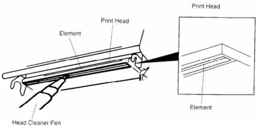
| Print Head | 1. Always turn off the printer before cleaning the print head.2. Allow the print head to cool for a minimum of one minute.3. Use a cotton swab (Head cleaner pen) and 100% ethanol to clean the print head surface. | Clean the print head when changing a new label roll |
 | ||
| Platen Roller | 1. Turn the power off.2. Rotate the platen roller and wipe it thoroughly with 100% ethanol and a cotton swab, or lint-free cloth. | Clean the platen roller when changing a new label roll |
| Tear Bar/Peel Bar | Use the lint-free cloth with 100% ethanol to wipe it. | As needed |
| Sensor | Compressed air or vacuum Monthly | |
| Exterior | Wipe it with water-dampened As needed | |
| cloth | ||
| Interior | Brush or vacuum As needed | |
Note:
- Do not touch printer head by hand. If you touch it careless, please use ethanol to clean it.
- Please use 100% Ethenol. DO NOT use medical alcohol, which may damage the printer head.
- Regularly clean the print head and supply sensors once change a new ribbon to keep printer performance and extend printer life.
6. Troubleshooting
The following guide lists the most common problems that may be encountered when operating this bar code printer. If the printer still does not function after all suggested solutions have been invoked, please contact the Customer Service Department of your purchased reseller or distributor for assistance.
6.1 LED Status
This section lists the common problems that according to the LED status and other problems you may encounter when operating the printer. Also, it provides solutions.
| LED Status / Color | Printer Status | Possible Cause | Recovery Procedure |
| OFF No response | No power * Turn on | the power switch.* Check if the green LED is lit on power supply. If it is not lit on, power supply is broken.* Check both power connections from the power cord to the power supply and from the power supply to the printer power jack if they are connected securely. | |
| Solid Green | ON The | printer is ready to use | * No action necessary. |
| Green with blinking | Pause The | printer is paused | * Press the FEED button to resume for printing. |
| Red with blinking | Error The | out of label or ribbon or the printer setting is not correct | 1. Out of label or ribbon* Load a roll of label and follow the instructions in loading the media then press the FEED button to resume for printing.* Load a roll of ribbon and follow the instructions in loading the ribbon then press the FEED button to resume for printing.2. Printer setting is not correct* Initialize the printer by instructions in “Power on Utility” or “Diagnostic Tool”. |
Note:
Printer status can be easily shown on the Diagnostic Tool. For more information about the Diagnostic Tool, please refer to the instruction in the software CD disk.
6.2 Print Quality
| Problem Possible Cause Recovery Procedure | ||
| Not Printing | Check if interface cable is well connected to the interface connector. | Re-connect cable to interface. |
| The serial port cable pin configuration is not pin to pin connected. | Please replace the cable with pin to pin connected. | |
| The serial port setting is not consistent between host and printer. | Please reset the serial port setting. | |
| The port specified in the Windows driver is not correct. | Select the correct printer port in the driver. | |
| The Ethernet IP, subnet mask, gateway is not configured properly. | Configure the IP, subnet mask and gateway. | |
| No print on the label | Label or ribbon loaded not correctly. | Follow the instructions in loading the media or loading the ribbon. |
| Ribbon run out. Loading the ribbon. | ||
| Continuous feeding labels | The printer setting may go wrong. | Please do the initialization and gap/black mark calibration. |
| Paper Jam | Gap/black mark sensor sensitivity is not set properly (sensor sensitivity is not enough) | Calibrate the gap/black mark sensor. |
| Make sure label size is set properly. | Set label size exactly as installed paper in the labeling software or program. | |
| Labels may be stuck inside the printer mechanism near the sensor area. | Remove the stuck label. | |
| Poor Print Quality | Top cover is not closed properly. | Close the top cover completely and make sure the right side and left side levers are latched properly |
| Check if supply is loaded correctly. | Reload the supply. | |
| Ribbon and media are incompatible. | Change the ribbon or label combination. | |
| Check if dust or adhesives are accumulated on the print head. | Clean the print head. | |
| Check if print density is set properly. | Adjust the print density and print speed. | |
| Check print head test pattern if head element is damaged. | Run printer self-test and check the print head test pattern if there is d missing in the pattern. | |
7. LED and Button Operation
7.1 LED
| LED Color Description | |
| Green/ Solid | This illuminates that the power is on and the device is ready to use. |
| Green/ Flash This | illuminates that the system is downloading data from PC to memory and the printer is paused. |
| Amber | This illuminates that the system is clearing data from printer. |
| Red / Solid This | illuminates printer head open, cutter error. |
| Red / Flash This | illuminates a printing error, such as head open, paper empty, paper jam, ribbon empty, or memory error etc. |
7.2 Button Operation
| Feed | ● Press the button when the LED is green.■ It feeds the label to the beginning of the next label. |
| Pause | ● Press the feed button during printing■ The printing job is suspended. |
| Ribbon Sensor and Gap/Black Mark Sensor Calibration | 1. Turn off the power switch.2. Hold on the button then turn on the power switch.3 Release the button when LED becomes red and blinking.(Any red will do during the 5 blinks).■ It will calibrate the ribbon sensor and gap/black mark sensor sensitivity.■ The LED color will be changed as following order:Amber → red (5 blinks) → amber (5 blinks) → green (5 blinks) → green/amber (5 blinks) → red/amber (5 blinks) → solid greenNote:Please select gap or black mark sensor by GAP or BLINE command prior to calibrate the sensor.For more information about GAP and BLINE command, please refer to TSPL2 programming manual. |
| Gap/Black Mark Sensor Calibratio, Label Length Measurement, Self Test and enter Dump Mode | 1. Turn off the power switch.2. Hold on the button then turn on the power switch.3. Release the button when LED becomes amber and blinking. (Any amber will do during the 5 blinks).■ The LED color will be changed as following order. Amber → red (5 blinks) → amber (5 blinks) → green (5 blinks) → green/amber (5 blinks) → red/amber (5 blinks) → solid green■ It calibrates the sensor and measures the label length and prints internal settings then enter the dump mode.Note:Please select gap or black mark sensor by GAP or BLINE command prior to calibrate the sensor.For more information about GAP and BLINE command, please refer to TSPL2 programming manual. |
| Printer Initialization | 1. Turn off the power switch.2. Hold on the button then turn on the power switch.3. Release the button when LED turns green after 5 amber blinks. (Any green will do during the 5 blinks).■ The LED color will be changed as following: Amber → red (5 blinks) → amber (5 blinks) → green (5 blinks) → green/amber (5 blinks) → red/amber (5 blinks) → solid greenNote:Always do gap/black mark sensor calibration after printer initialization. |
| Black Mark Sensor Calibration | 1. Turn off the power switch.2. Hold on the button then turn on the power switch.3. Release the button when LED turns green/amber after 5 green blinks. (Any green/amber will do during the 5 blinks).■ The LED color will be changed as following: Amber → red (5 blinks) → amber (5 blinks) → green (5 blinks) → green/amber (5 blinks) → red/amber (5 blinks) → solid green |
| Gap Sensor Calibration | 1. Turn off the power switch.2. Hold on the button then turn on the power switch.3. Release the button when LED turns red/amber after 5 green/amber blinks. (Any red/amber will do during the 5 blinks).■ The LED color will be changed as following: Amber → red (5 blinks) → amber (5 blinks) → green (5 blinks) → green/amber (5 blinks) → red/amber (5 blinks) → solid green |
| Skip AUTO.BAS | 1. Turn off printer power.2. Press the FEED button and then turn on power.3. Release the FEED button when LED becomes solid green.■ The LED color will be changed as following: Amber → red (5 blinks) → amber (5 blinks) → green (5 blinks) → green/amber (5 blinks) → red/amber (5 blinks) → solid green4. Printer will be interrupted to run the AUTO.BAS program. |
Revise History
| Date Content | |
| 2009/10/14 *Revise section 3.8*Add section 3.9 | |
| 2010/11/23 *Revise section 1, 2.3 and 3.1 |
For sales within the United Kingdom, mainland Europe, the Middle East and Africa please contact:
Kroy Europe Limited Unit B7, Worton Drive, Worton Grange, Reading, Berkshire RG2 0LZ England
Tel: +44 (0) 118 986 5200
Fax: +44 (0) 118 986 5205
Website: www.kroyeurope.com
Emails: Product information : info@kroyeurope.com
Technical support : support@kroyeurope.com
For information and sales in North & South America, Australia and the Asia-Pacific regions please contact:
Kroy LLC, 3830 Kelley Avenue, Cleveland Ohio 44114 USA
Tel: +1 (216) 426-5600
Printed in the United Kingdom