K4730 - Label printer Kroy - Free user manual and instructions
Find the device manual for free K4730 Kroy in PDF.


User questions about K4730 Kroy
0 question about this device. Answer the ones you know or ask your own.
Ask a new question about this device
Download the instructions for your Label printer in PDF format for free! Find your manual K4730 - Kroy and take your electronic device back in hand. On this page are published all the documents necessary for the use of your device. K4730 by Kroy.
USER MANUAL K4730 Kroy
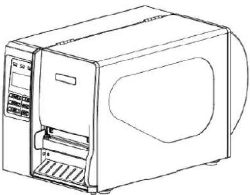
KROY K4710, K4730, K4760, K4652NB, K4653NB series
THERMAL TRANSFER / DIRECT THERMAL BAR CODE PRINTER
USER'S
MANUAL
natural_image
Line drawing of a microwave oven with control panel and ventilation slots (no text or symbols)Contents
- Introduction ...... 1
1.1 Product Introduction .... 1
1.2 Compliances .... 1 - Operations Overview ...... 3
2.1 Unpacking and Inspection ....3
2.2 Printer Overview ...... 4
2.2.1 Front View 4
2.2.2 Interior view....5
2.2.3 Rear View....6
2.3 Operator Controls 8
2.3.1 Front Panel Display 8
2.3.2 LED Indicators 8
2.3.3 Front Panel Keys 9
2.4 Setting Up the Printer 9
2.5 Installation of Ribbon 10
2.5.1 Loading Ribbon 10
2.5.2 Remove Used Ribbon....13
2.6 Installation of Media 14
2.6.1 Loading Roll Labels....14
2.6.2 Loading Fan-fold Labels ...... 17
2.6.3 Loading Media for Peel-off Mode (Option)....19
2.6.4 Remove Liner (Option) 21
2.6.5 Loading Media in Rewind Liner with Label Mode (Option) .....22
2.6.6 Remove Labels from Internal Rewind (Option) 24
2.7 Adjustment Knob 25
2.7.1 Print head Pressure Adjustment Knob 25
2.7.2 Print Head Burn Line Adjustment Knob....25
- Menu Function 27
3.1 Setup Menu Overview....28
3.1.1 Printer Setup 29
3.1.2 Sensor....36
3.1.3 Serial Comm....44
3.1.4 Ethernet 47
3.2 File Manager....50
3.2.1 File List ....50
3.2.2 Avail. Memory....51
3.2.3 Del. All Files....51
3.3 Diagnostics ....52
3.3.1 Print Config. 52
3.3.2 Dump Mode ....53
3.3.3 Rotate Cutter ....54
3.4 Language....54
3.5 Service....55
3.5.1 Initialization....55
3.5.2 Mileage Info....56
4. Diagnostic Tool 57
4.1 Start the Diagnostic Tool....57
4.2 Printer Function (Calibrate sensor, Ethernet setup, RTC setup....) 58
5. Troubleshooting ..... 59
5.1 Common Problems....59
5.2 Mechanism Fine Adjustment to Avoid Ribbon Wrinkles 63
6. Maintenance 65
1. Introduction
1.1 Product Introduction
Thank you very much for purchasing our thermal transfer printer.
This printer is designed with die-casting aluminum chassis and print mechanism, metal cover with large clear media view window, which ensuring to work for the extreme and heavy duty industrial environment and applications.
With a back-lit graphic LCD display, the printer status is user friendly and can be easily managed. The moveable sensor design can accept wide range of label media. All of the most frequently used bar code formats are included. Fonts and bar codes can be printed in any one of the four directions. This printer is built-in the high quality, high performance MONOTYPE IMAGING® True Type font engine and one CG Triumvirate Bold
Condensed smooth font. With flexible firmware design, users can also download True Type Fonts from a PC into the printer memory for printing labels. In addition to the scalable font, there is also a choice of five different sizes of alphanumeric bitmap fonts, OCR-A and OCR-B fonts. By integrating rich features, it is the most cost-effective and high performance printer in its class!
1.2 Compliances
CE Class A:
EN55022:1998+A1:2000+A2:2003:
EN55024:1998+A1:2001+A2:2003:
EN 61000-4 SERIES REGULATIONS
ETSI EN 301 489-17:V1.2.1(2002-08)
FCC:
CFR 47, Part 15/CISPR 22 3RD EDITION:1997, Class A
This device complies with Part 15 of the FCC Rules. Operation is subject to the following two conditions.
(1)This device may not cause harmful interference, and
(2)This device must accept any interference received, including interference that may cause undesired operation.
ANSI C63.4:2003
CANADIAN ICES-003
C-Tick:
AS/NZS CISPR22 (Class A)
UL, CUL
UL 60950 3 ^rd
TÜV-GS:
EN60950: 2000
(CAUTION: Danger of explosion if battery is incorrectly replaced. Replace only with the same or equivalent type recommended by the manufacturer. Dispose of used batteries according to the manufacturer instructions.)
"ORSICHT"
2. Operations Overview
2.1 Unpacking and Inspection
This printer has been specially packaged to withstand damage during shipping. Please carefully inspect the packaging and printer upon receiving the bar code printer. Please retain the packaging materials in case you need to reship the printer.
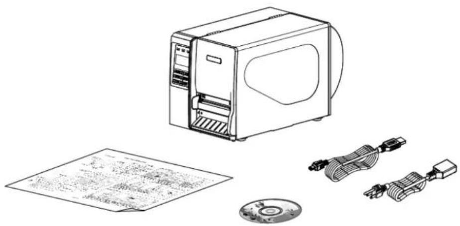
Unpacking the printer, the following items are included in the carton.
■ One printer unit
■ One Windows labeling software/Windows driver CD disk
■ One quick installation guide
■ One power cord
■ One USB interface cable
natural_image
Line drawing of a microwave oven with attached cables and a printed paper sheet (no text or symbols)If any parts are missing, please contact the Customer Service Department of your reseller or distributor.
2.2 Printer Overview
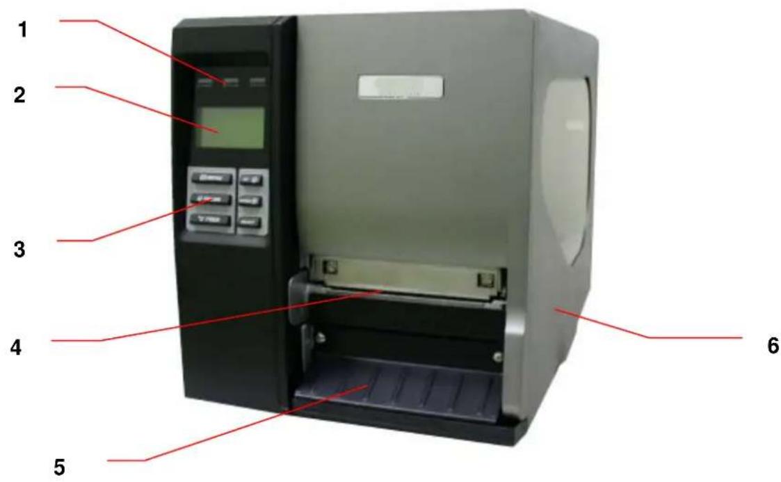
2.2.1 Front View
text_image
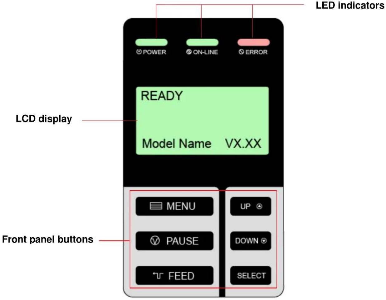
1 2 3 4 5 6- LED indicators
- LCD display
- Front panel buttons
- Paper exit chute
- Lower front cover
- Printer right side cover
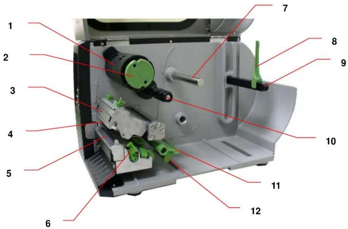
2.2.2 Interior view
text_image
Labeled diagram of a mechanical device with numbered parts for identification- Ribbon rewind spindle
- Ribbon release button
- Ribbon guide plate
- Print head
- Platen roller
- Print head release lever
- Media guide bar
- Label roll guard
- Label supply spindle
- Ribbon supply spindle
- Damper
- Label guide
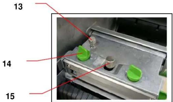
- Z axis mechanism adjustment knob
- Print head pressure adjustment knob
- Print head secure screw
- Ribbon sensor
- Media sensor
16
17
text_image
13 14 15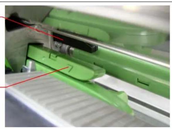
natural_image
Close-up of a green plastic mechanical component with red alignment lines (no text or symbols visible)2.2.3 Rear View
text_image
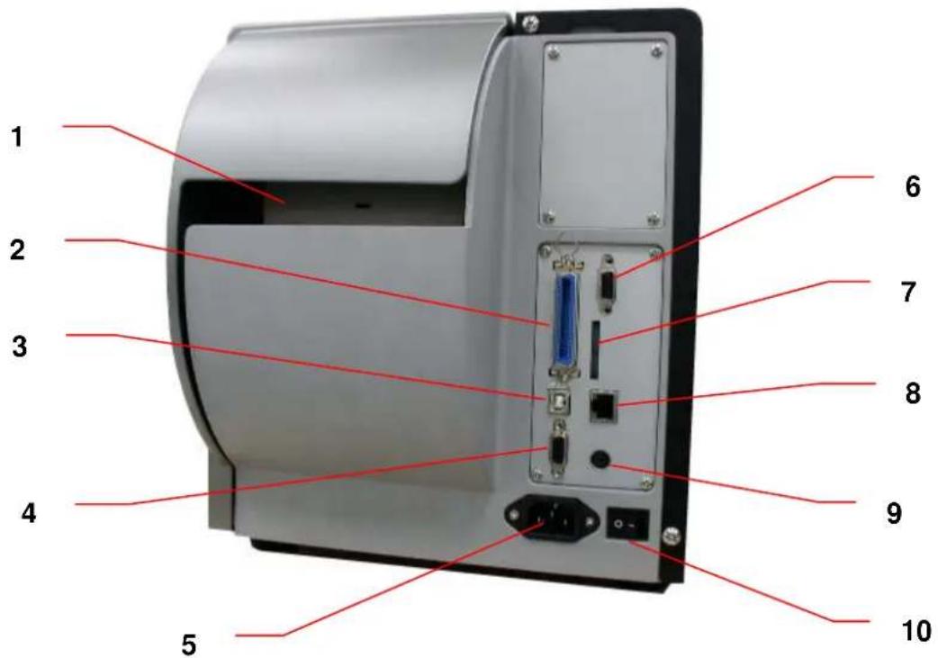
1 2 3 4 5 6 7 8 9 10- Fan-fold paper entrance chute
- Centronics interface
- USB interface
- RS-232C interface
- Power jack socket
- GPIO interface
*7. SD card slot - Ethernet interface
- PS/2 interface
- Power switch
Note:
- SD card slot, Ethernet interface and PS/2 interface are standard interfaces for M4210/M4306/T-0612/T-0613 models, but optional for M-2406 Plus/M-3406 Plus/T-462 Plus/T-443 Plus models.
- GPIO interface card includes SD card slot, Ethernet and PS/2 interfaces. So GPIO interface is an factory option for M4210/M4306/T-0612/T-0613, but a dealer option for M-2406 Plus/M-3406 Plus/T-462 Plus/T-443 Plus models.
| V1.0, V1.1 microSD | 256 MB Transcend, | Panasonic |
| V1.0, V1.1 microSD | 512 MB Panasonic | |
| V1.0, V1.1 microSD | 1 GB Transcend, | Panasonic |
| V2.0 SDHC CLASS 4 | microSD 4 GB | Panasonic |
| V2.0 SDHC CLASS 6 | microSD 4 GB | Transcend |
| V1.0, V1.1 miniSD | 128 MB Transcend, | Panasonic |
| V1.0, V1.1 miniSD | 256 MB Transcend, | Panasonic |
| V1.0, V1.1 miniSD | 512 MB Transcend, | Panasonic |
| V1.0, V1.1 miniSD | 1 GB Transcend, | Panasonic |
| V2.0 SDHC CLASS 4 | miniSD 4 GB | Transcend |
| V2.0 SDHC CLASS 6 | miniSD 4 GB | |
| - The DOS FAT file system is supported for the SD card.- Folders/files stored in the SD card should be in the 8.3 filename format- The miniSD/microSD card to SD card slot adapter is required. | ||
2.3 Operator Controls
2.3.1 Front Panel Display
text_image
LED indicators POWER ON-LINE ERROR READY Model Name VX.XX LCD display MENU UP PAUSE DOWN FEED SELECT Front panel buttons2.3.2 LED Indicators
| LED | Status | Indication |
| POWER | Off The printer | power is turned off |
| On The printer | power is turned on | |
| ON-LINE | On Printer is ready | |
| Blinking | Pause | |
| Downloading data into printer. | ||
| ERROR | Off Printer is ready | |
| On "CARRIAGE OPEN" or "CUTTER ERROR" | ||
| Blinking "NO PAPER", "PAPER JAM" or "NO RIBBON" | ||
2.3.3 Front Panel Keys
| Keys | Function |
| MENU | 1. Enter the menu2. Exit from a menu or cancel a setting and return to the previous menu |
| PAUSE | Pause/Resume the printing process |
| FEED | Advance one label |
| UP | Scroll up the menu list |
| DOWN | Scroll down the menu list |
| SELECT | Enter/Select cursor located option |
2.4 Setting up the Printer
- Place the printer on a flat, secure surface.
- Make sure the power switch is off.
- Connect the printer to the computer with the provided USB cable.
- Plug the power cord into the AC power cord socket at the rear of the printer, and then plug the power cord into a properly grounded power outlet.
2.5 Installation of Ribbon
2.5.1 Loading Ribbon
-
Lift open printer right side cover.
-
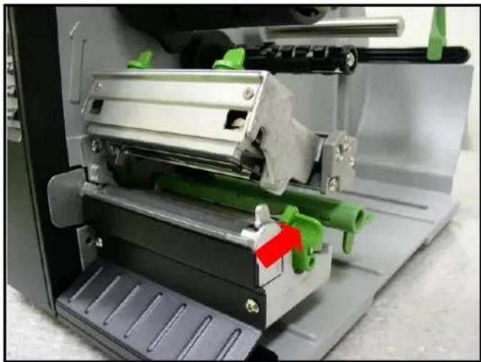
Push the print head release lever to open the print head mechanism.
natural_image
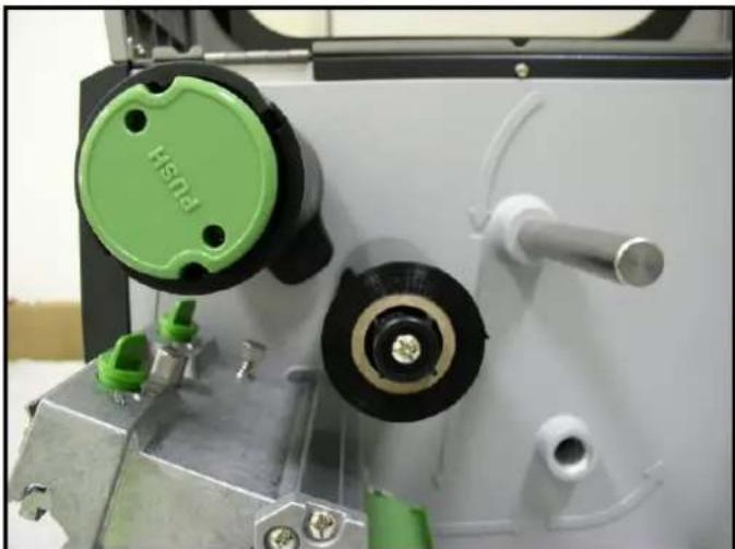
Close-up of a 3D printer's internal mechanism with green plastic components and a red arrow indicating a specific part (no text or symbols visible)- Install the ribbon onto the ribbon supply spindle.
natural_image
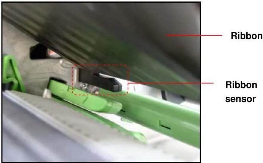
Close-up of a mechanical device with green circular components and a central black circular component (no visible text or symbols)- Thread the ribbon through the ribbon sensor slot and then through the open space in between print head and platen.
text_image
Ribbon Ribbon sensor-
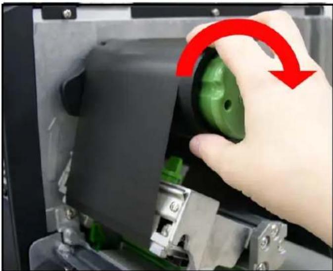
Wrap the ribbon onto the ribbon rewind spindle, ensuring that the ribbon is flat and wrinkle free.
-
Wind the ribbon clockwise about 3\~5 circles onto the ribbon rewind spindle until it is smooth and properly stretched.
natural_image
Hand operating a green push-button switch inside a mechanical device (no text or symbols visible)- Close the print head mechanism making sure the latches are engaged properly.
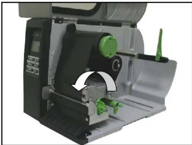
natural_image
Close-up of a mechanical device with green components and a white curved arrow indicating rotation or movement (no text or symbols visible)- Loading path for ribbon
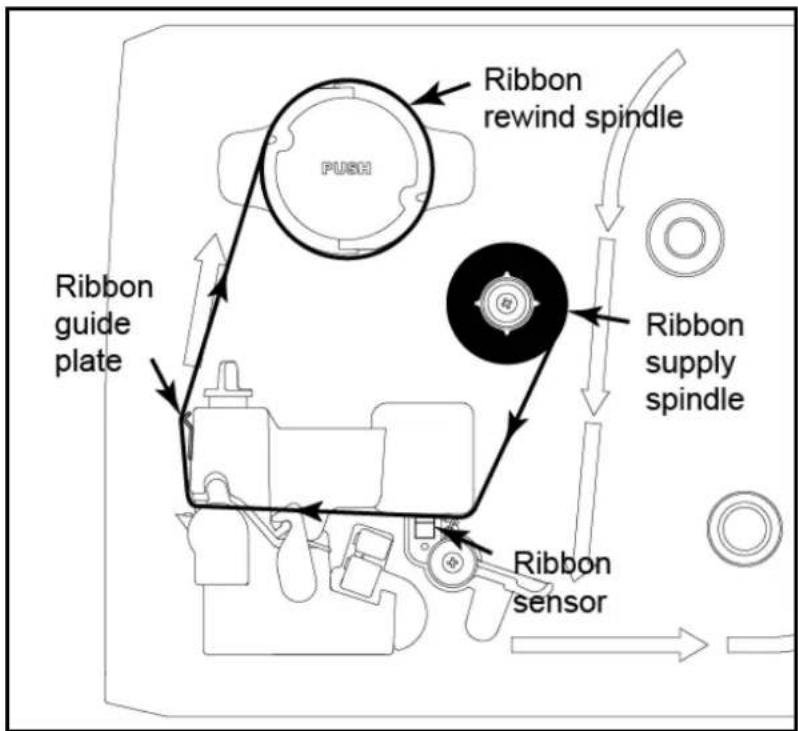
text_image
Ribbon rewind spindle PUSH Ribbon guide plate Ribbon supply spindle Ribbon sensor2.5.2 Remove Used Ribbon
- Break the ribbon between ribbon guide plate and the ribbon rewind spindle.
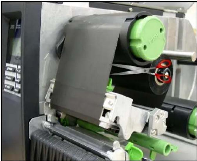
natural_image
Close-up of a mechanical printing or printing machine with green and black components, no visible text or symbols.- Push the ribbon release button to release the ribbon on the ribbon rewind spindle.
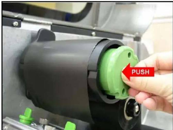
natural_image
Close-up of a hand inserting a green plastic component into a black cylindrical device, with a red 'PUSH' arrow indicating the action (no text or symbols on the device itself)- Then, slide off the ribbon from ribbon rewind spindle.
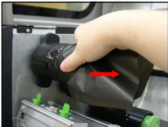
natural_image
Hand pressing a black plastic component into a 3D printer machine, with green adjustment knobs and red directional arrow (no text or symbols)2.6 Installation of Media
2.6.1 Loading Roll Labels
- Lift open printer right side cover.
- Push the print head release lever to open the print head mechanism.
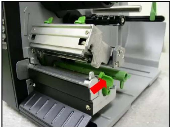
natural_image
Close-up of a mechanical device with green and red components, no visible text or symbols- Move the label roll guard horizontally to the end of label spindle then flip down the label roll guard.
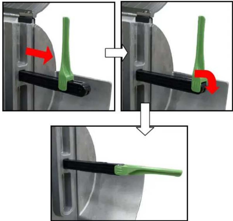
natural_image
Three-step diagram showing a green tool being inserted into a black plastic holder, with red arrows indicating motion direction (no text or symbols)- Place the roll of media on the label supply spindle. Flip up the label roll guard. Move the label roll guard horizontally to gently fit the width of label roll.
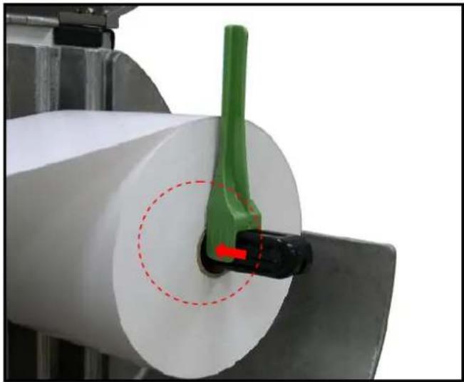
natural_image
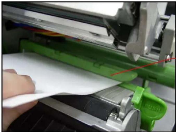
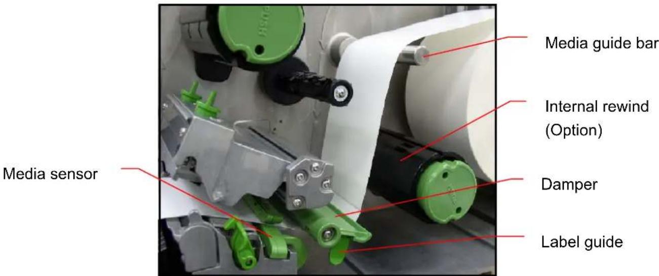
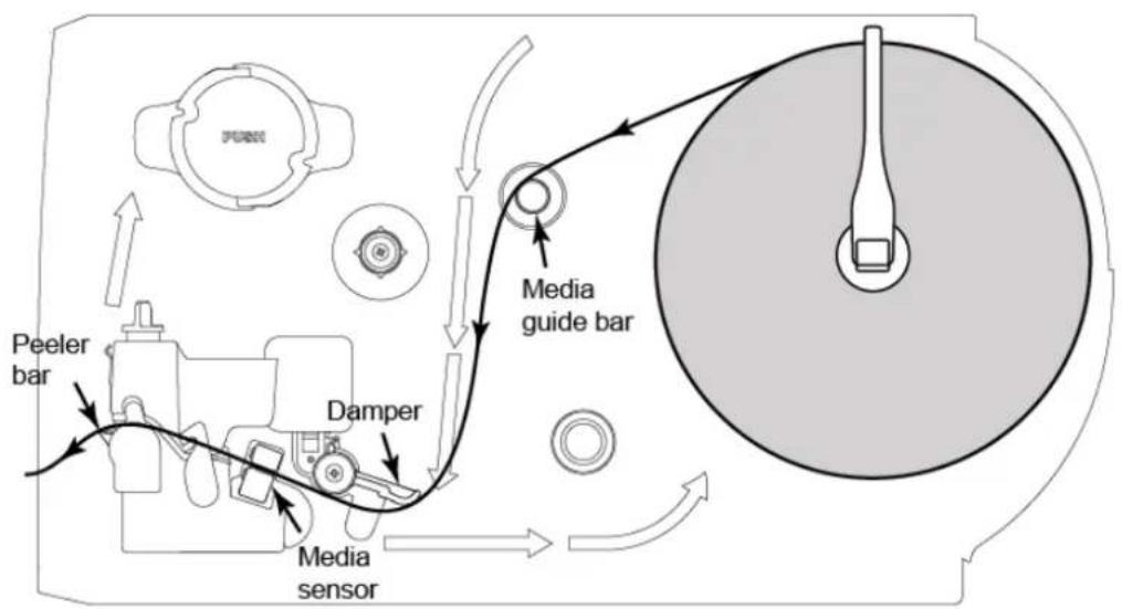
Close-up of a green tool interacting with a white paper roll, no visible text or symbols- Pull label roll leading edge forward through the media guide bar, damper, media sensor and place the label leading edge onto the platen roller.
natural_image
Close-up of a hand using a green printer to press white paper, with a red push button visible (no text or symbols on the printer itself)Media sensor
text_image
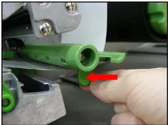
Media guide bar Internal rewind (Option) Damper Label guide Media sensor- Adjust the label guide to fit the width of the label.
natural_image
Close-up of a green plastic pipe fitting with a red arrow pointing to a small component, held by a hand (no text or symbols visible)- Close the print head mechanism making sure the latches are engaged properly.
- Using the LCD panel set the media sensor type and calibrate the selected sensor. (Please refer to section 3.1.2)
Note: Please calibrate the gap/black mark sensor when changing media.
- Loading path for roll labels
flowchart
graph TD
    A["Peeler bar"] --> B["Damper"]
    B --> C["Media guide bar"]
    C --> D["Camera body"]
    style A fill:#f9f,stroke:#333
    style B fill:#ccf,stroke:#333
    style C fill:#cfc,stroke:#333
    style D fill:#fcc,stroke:#333
2.6.2 Loading Fan-fold Labels
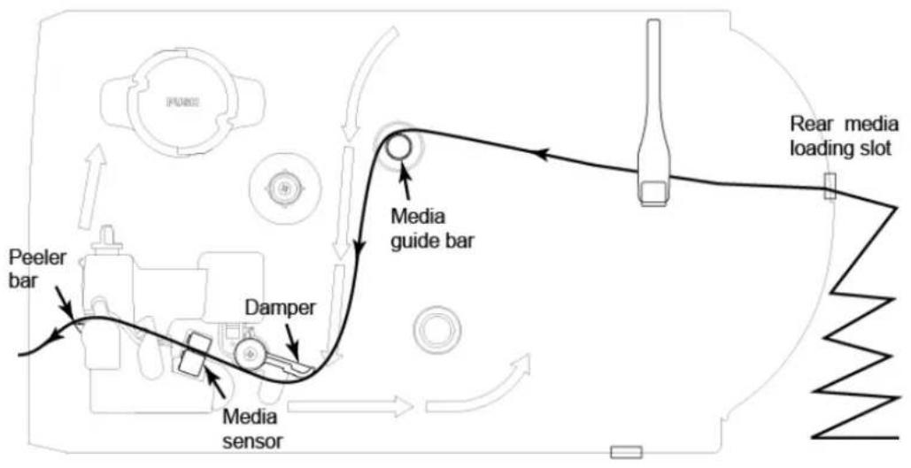
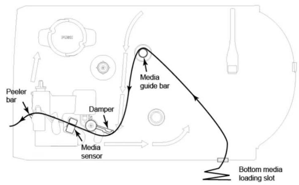
Fan-fold media feeds through either the bottom or rear external label entrance chute.
-
Lift open printer right side cover.
-
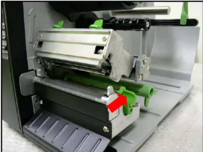
Push the print head release lever to open the print head mechanism.
natural_image
Close-up of a mechanical device with green components and a red arrow indicating a specific part (no visible text or symbols)- Insert the fan-fold media through the bottom or rear external label entrance chute.
- Pull fan-fold label leading edge forward through the media guide bar, damper media sensor and place the label leading edge onto the platen roller.
- Adjust the label guide by sliding to fit the paper width.
- Close the print head mechanism making sure the latches are engaged properly.
- Set the media sensor type and calibrate the selected sensor. (Please refer to section 3.1.2)
Note: Please calibrate the gap/black mark sensor when changing media.
- Loading path for fan-fold labels
flowchart
graph TD
    A["Peeler bar"] --> B["Damper"]
    B --> C["Media sensor"]
    C --> D["Media guide bar"]
    D --> E["Rear media loading slot"]
    style A fill:#f9f,stroke:#333
    style B fill:#ccf,stroke:#333
    style C fill:#cfc,stroke:#333
    style D fill:#fcc,stroke:#333
    style E fill:#ffc,stroke:#333
flowchart
graph TD
    A["Bottom media loading slot"] --> B["Media guide bar"]
    B --> C["Damper"]
    C --> D["Peeler bar"]
    D --> E["Media sensor"]
    E --> F["Control panel with sensors and indicator lights"]
2.6.3 Loading Media for Peel-off Mode (Option)
- Lift open printer right side cover.
- Push the print head release lever to open the print head mechanism.
- Move the label roll guard horizontally to the end of label spindle then flip down the label roll guard.
- Place the roll of media on the label supply spindle. Flip up the label roll guard. Move the label roll guard horizontally to fit the width of label roll.
- Pull label roll leading edge forward through the media guide bar, damper media sensor and place the label leading edge onto the platen roller.
- Adjust the label guide to fit the width of the label.
- Using the LCD panel set the media sensor type and calibrate the selected sensor. (Please refer to section 3.1.2)
- Then, pull approximately 650mm of label through the front of the printer.
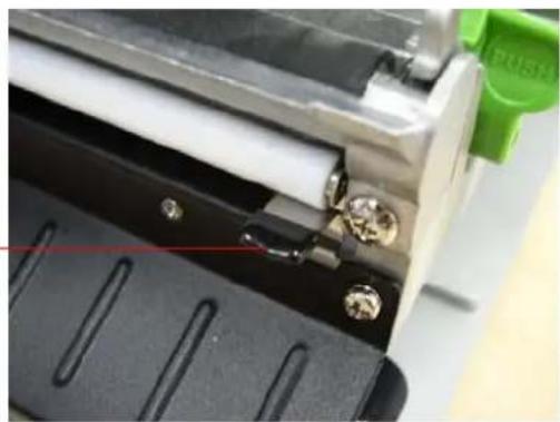
- Push down the peel-off roller release lever.
Peel-off roller release lever
natural_image
Close-up of a mechanical device with black base and green handle, no visible text or symbols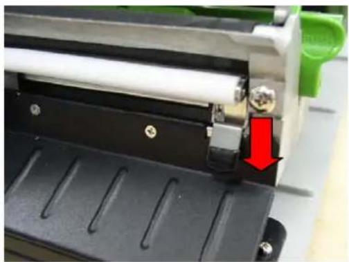
natural_image
Close-up of a mechanical device with a red arrow pointing to a component, no visible text or symbols- Feed the label between peel-off roller and platen roller.
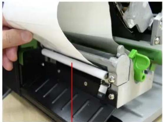
natural_image
Close-up of a hand pressing down on a mechanical device with paper roll and green handle (no visible text or symbols)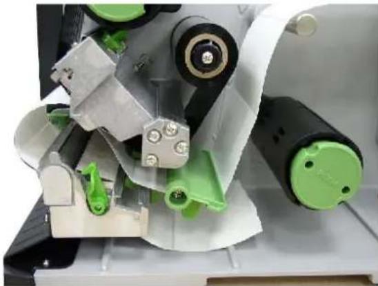
natural_image
Close-up of mechanical components with green and gray parts, no visible text or symbolsPeel-off roller
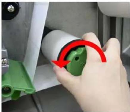
- Wrap the label onto the internal rewinder spindle and rotate the spindle counter-clockwise about 3\~5 full rotations until the label is taut.
natural_image
Close-up of a hand holding a green cylindrical component with a red curved arrow indicating rotation (no text or symbols visible)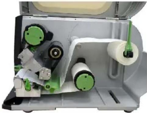
natural_image
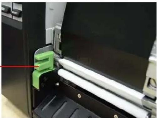
Close-up of a mechanical device with green and black components, no visible text or symbols- Lift up the peel-off roller release lever and close the print head mechanism.
- Move the peel-off sensor toward the paper exit chute.
Peel-off sensor
natural_image
Close-up of a printer's side panel showing white paper strips and a green plastic clip, with no visible text or symbols.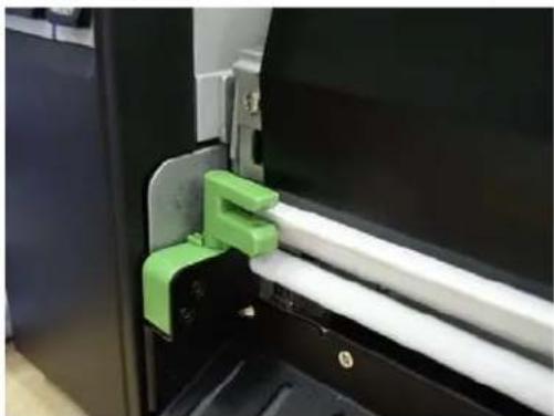
natural_image
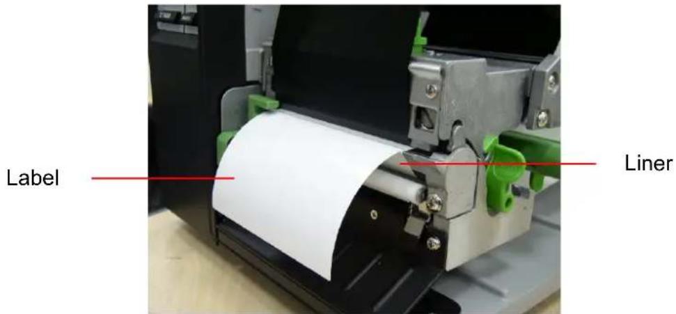
Close-up of a mechanical assembly with green and white components, no visible text or symbols- Peeling will automatically start. Press the FEED button to test.
text_image
Label LinerNote:
Please calibrate the gap/black mark sensor when changing media.
2.6.4 Remove Liner (Option)
- Break the liner between peel-off roller and the internal rewinder spindle.
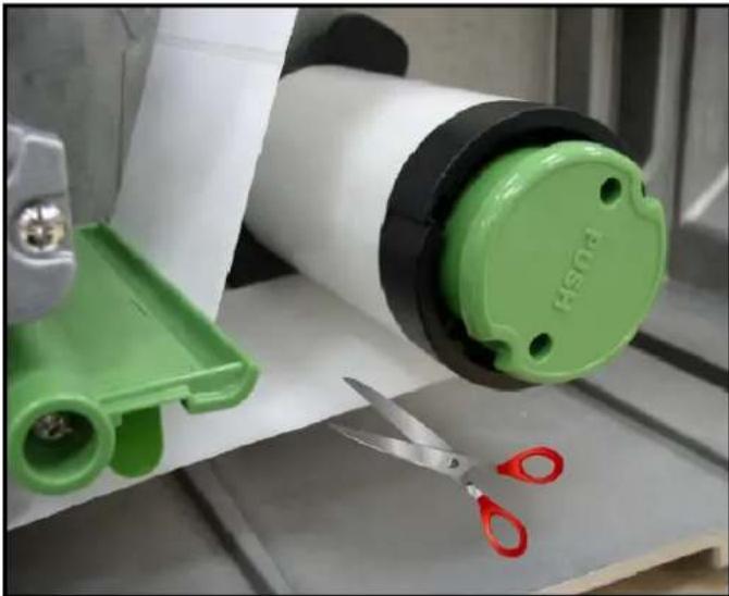
natural_image
Close-up of a sewing machine with green and white components, scissors cutting on a wooden surface (no visible text or symbols)- Push the liner release button to release the liner on the internal rewinder spindle.
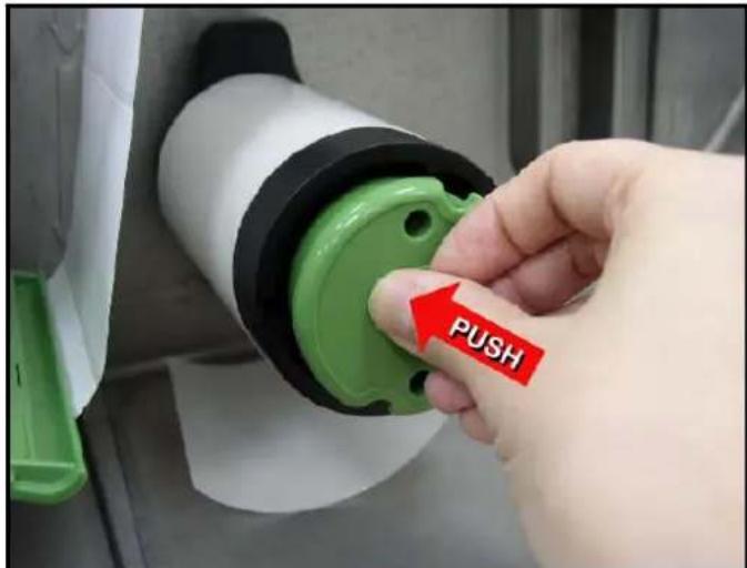
text_image
PUSH- Then, slide off the liner from internal rewinder spindle.
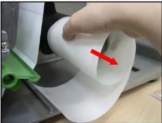
natural_image
Close-up of a hand holding a white cylindrical object with a red arrow pointing to it, next to a green plastic clip (no text or symbols visible)2.6.5 Loading Media in Rewind Liner with Label Mode (Option)
This mode can rewind the media including liner and label on the rewind spindle.
-
Lift open printer right side cover.
-
Insert the supply holder guide and paper core into the internal rewind for 1" core label roll.
Insert the supply holder guide, 3" label core adapter and paper core into the internal rewind for 3" core label roll.
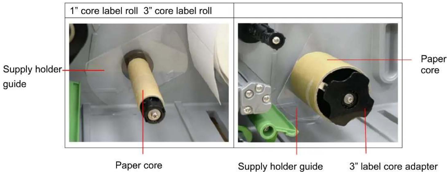
text_image
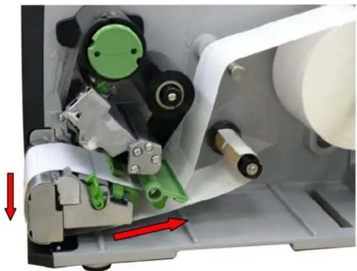
1" core label roll 3" core label roll Supply holder guide Paper core Paper core Supply holder guide 3" label core adapter- Insert media into the printer label spindle. Pull label roll leading edge forward through the media guide bar, damper media sensor and place the label leading edge onto the platen roller. (Please refer to section 2.6.1)
- Then, pull approximately 650mm of label through the label redirect front panel.
- Wrap the label onto the internal rewind spindle and stick the label onto the paper core.
natural_image
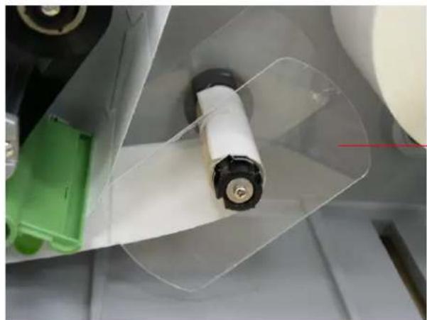
Close-up of a mechanical assembly with green components and red directional arrows indicating movement (no text or symbols)- Insert another supply holder guide into the internal rewind for 1" core label roll.
natural_image
Close-up of a mechanical component with a white cylindrical part and green plastic housing, no visible text or symbols.Supply holder guide
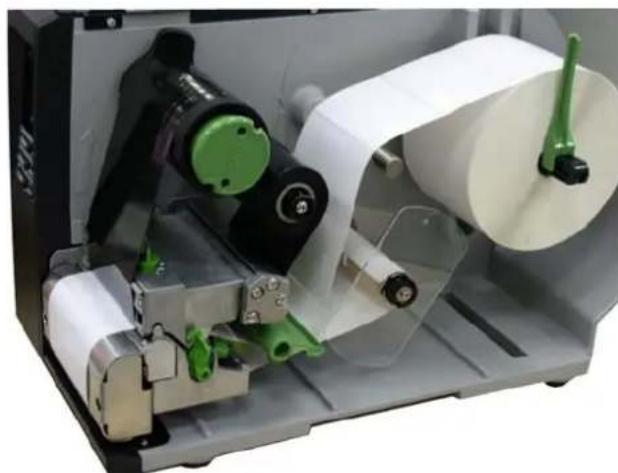
- Using the LCD panel set the media sensor type and calibrate the selected sensor. (Please refer to section 3.1.2)
natural_image
Close-up of a mechanical printing or paper cutting machine with green and black components (no visible text or symbols)Note:
Please calibrate the gap/black mark sensor when changing media.
2.6.6 Remove Labels from Internal Rewind (Option)
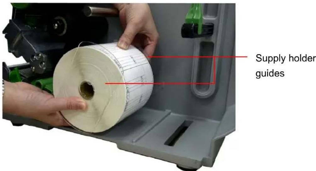
- Slide off the labels with supply holder guides from internal rewind spindle.
text_image
Supply holder guides2.7 Adjustment Knob
2.7.1 Print head Pressure Adjustment Knob
natural_image
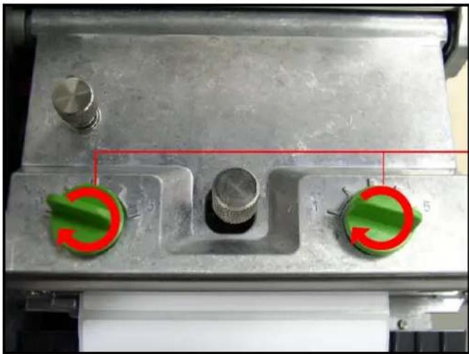
Close-up of a metallic mechanical component with three green circular switches and a red measurement line (no text or symbols visible)Print head pressure adjustment knobs
The print head pressure adjustment knob has 5 levels of adjustment. Because the printer's media alignment is to the left side of mechanism, different media widths require different pressure to print correctly. Adjustment may required depending on media thickness and widths to obtain the best print quality. For example, if the label width is 4", adjust both print head pressure adjustment knobs to the same level. If the label is less than 2" wide, increase the left side print head pressure by rotating the adjustment knob clockwise and decrease the right side pressure by rotating the adjustment knob counter-clockwise to level 1.
2.7.2 Print Head Burn Line Adjustment Knob
natural_image
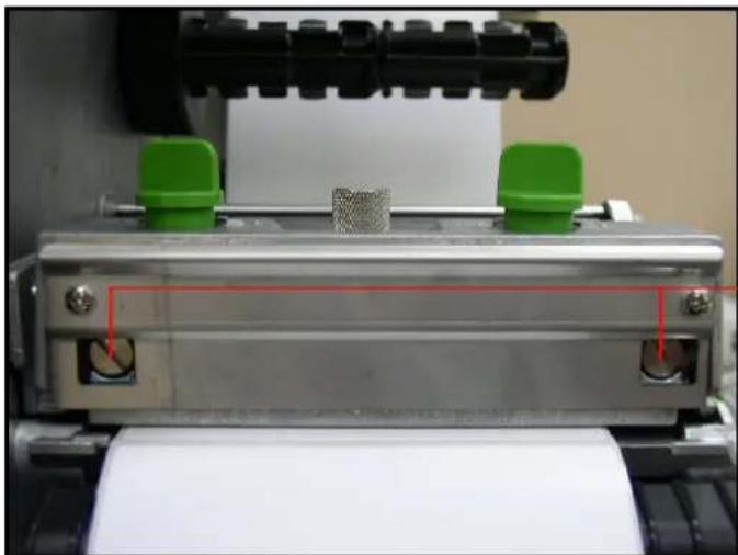
Close-up of a mechanical testing machine with green and black components, showing paper roll and alignment lines (no text or symbols visible)Print head burn line adjustment knobs
The print head burn line adjustment knobs are used to fine tune the print quality for
different thickness of media. Turning the knobs adjusts the print head's burn line forward or backward as it relates to the platen roller.
Caution: Incorrectly adjusting these knobs can lead to poor print quality and may cause damage to the printer. Proceed with caution.
The print head burn line default is set for general purpose printing media (plain paper and paper thickness less than 0.20mm).
Poor print quality when using paper thicker than 0.20mm may be due to the print head burn line not being at the optimized position. To improve the print quality, increase the head pressure or adjust the knobs counter-clockwise to move print head burn line toward the paper out direction then print again. Continue to adjust the burn line position and test print as necessary until the printout image is clear.
3. Menu Function
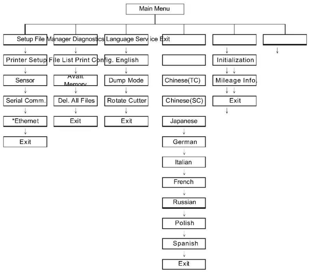
Main Menu Overview
flowchart
graph TD
    A["Main Menu"] --> B["Setup File"]
    A --> C["Manager Diagnostics"]
    A --> D["Language Service"]
    A --> E["Exit"]
    B --> F["Printer Setup"]
    F --> G["Sensor"]
    G --> H["Serial Comm."]
    H --> I["*Ethernet"]
    I --> J["Exit"]
    C --> K["File List Print Config"]
    K --> L["Avail. Memory"]
    L --> M["Del. All Files"]
    M --> N["Exit"]
    D --> O["fig. English"]
    O --> P["Dump Mode"]
    P --> Q["Rotate Cutter"]
    Q --> R["Exit"]
    E --> S["Initialization"]
    S --> T["Mileage Info."]
    T --> U["Chinese(TC)"]
    T --> V["Chinese(SC)"]
    T --> W["Exit"]
    E --> X["Japanese"]
    X --> Y["German"]
    Y --> Z["Italian"]
    Z --> AA["French"]
    AA --> AB["Russian"]
    AB --> AC["Polish"]
    AC --> AD["Spanish"]
    AD --> AE["Exit"]
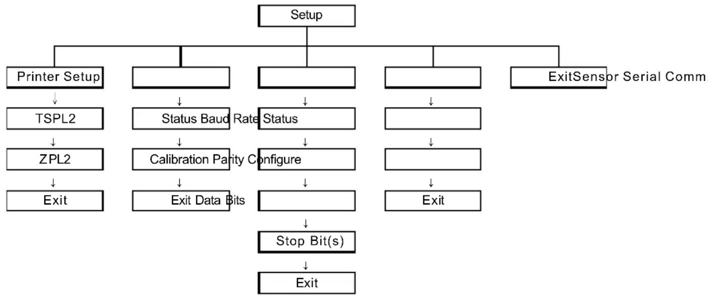
3.1 Setup Menu Overview
flowchart
graph TD
    A["Setup"] --> B["Printer Setup"]
    A --> C["Status Baud Rate"]
    A --> D["Status"]
    A --> E["Exit Sensor Serial Comm."]
    B --> F["TSPL2"]
    C --> G["ZPL2"]
    D --> H["Calibration Parity Configure"]
    E --> I["Exit"]
    F --> J["Exit Data Bits"]
    G --> K["Stop Bit(s)"]
    H --> L["Exit"]
    I --> M["Exit"]
3.1.1 Printer Setup
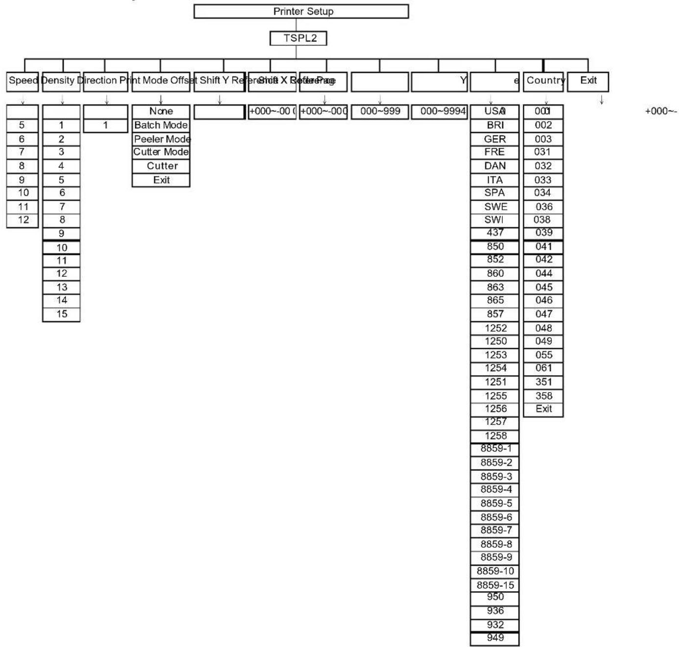
flowchart
graph TD
    A["Printer Setup"] --> B["TSPL2"]
    B --> C["Speed"]
    B --> D["Density"]
    B --> E["Direction"]
    B --> F["Print Mode Offset"]
    B --> G["Shift Y Refr"]
    B --> H["Shift X Refr"]
    B --> I["Reference"]
    B --> J["None"]
    B --> K["+000~000"]
    B --> L["+000~000"]
    B --> M["000~999"]
    B --> N["000~9994"]
    B --> O["Y"]
    B --> P["e"]
    B --> Q["Country"]
    B --> R["Exit"]
    C --> S["5"]
    C --> T["6"]
    C --> U["7"]
    C --> V["8"]
    C --> W["9"]
    C --> X["10"]
    C --> Y["11"]
    C --> Z["12"]
    D --> AA["1"]
    E --> AB["1"]
    F --> AC["None"]
    F --> AD["Batch Mode"]
    F --> AE["Peeler Mode"]
    F --> AF["Cutter Mode"]
    F --> AG["Cutter"]
    F --> AH["Exit"]
    G --> AI["None"]
    G --> AJ["+000~000"]
    G --> AK["+000~000"]
    G --> AL["000~999"]
    G --> AM["000~9994"]
    I --> AN["USA"]
    I --> AO["BRI"]
    I --> AP["GER"]
    I --> AQ["FRE"]
    I --> AR["DAN"]
    I --> AS["ITA"]
    I --> AT["SPA"]
    I --> AU["SWE"]
    I --> AV["SWI"]
    I --> AW["437"]
    I --> AX["850"]
    I --> AY["852"]
    I --> AZ["860"]
    I --> BA["863"]
    I --> BB["865"]
    I --> BC["857"]
    I --> BD["1252"]
    I --> BE["1250"]
    I --> BF["1253"]
    I --> BG["1254"]
    I --> BH["1251"]
    I --> BI["1255"]
    I --> BJ["1256"]
    I --> BK["1257"]
    I --> BL["1258"]
    I --> BM["8859-1"]
    I --> BN["8859-2"]
    I --> BO["8859-3"]
    I --> BP["8859-4"]
    I --> BQ["8859-5"]
    I --> BR["8859-6"]
    I --> BS["8859-7"]
    I --> BT["8859-8"]
    I --> BU["8859-9"]
    I --> BV["8859-10"]
    I --> BW["8859-15"]
    I --> BX["950"]
    I --> BY["936"]
    I --> BZ["932"]
    I --> CA["949"]
3.1.1.1 Speed:
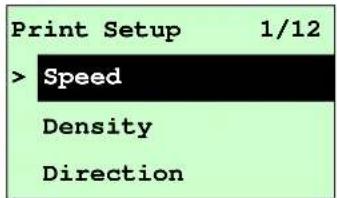
text_image
Print Setup 1/12 > Speed Density Direction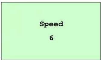
text_image
Speed 6Use this option to setup print speed. The available print speed is between 4\~12 ips and each increment/decrement is 1 ips. The default print speed is 6 ips.
Press UP Ⓧ key to raise the print speed, and press DOWN Ⓧ key to decrease print speed. Press SELECT key to set it into printer. Press ☐ MENU key to cancel the setting and return to the previous menu.
Note: If printing from enclosed software/driver, the software/driver will send out the SPEED command, which will overwrite the setting set from the front panel.
3.1.1.2 Density:
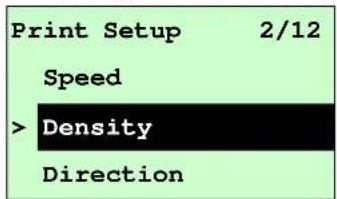
text_image
Print Setup 2/12 Speed > Density Direction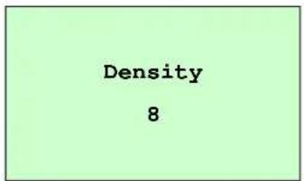
text_image
Density 8Use this option to setup printing darkness. The available setting is from 0 to 15, and the step is 1. Printer default density is 8. You may need to adjust your density based on selected media.
Press UP ☑ and DOWN ☑ to increase/decrease the printing darkness. Press SELECT key to enable the setting. Press ⚡️ keys to cancel the setting and return to the previous menu.
Note: If printing from enclosed software/driver, the software/driver will send out the DENSITY command, which will overwrite the setting set from the front panel.
3.1.1.3 Direction:
text_image
Print Setup 3/12 Speed Density > Direction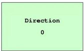
text_image
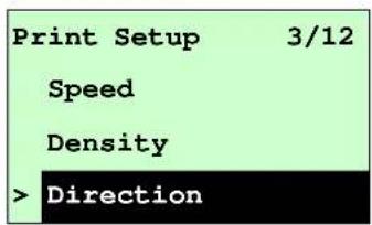
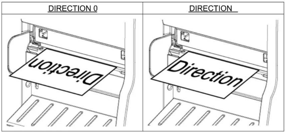
Direction 0The direction setting value is either 1 or 0. Use this option to setup the printout direction. Printer default printout direction is DIRECTION 0.
Press UP ⚙ key to set the direction as 1, and DOWN ⼑ to set it as 0, and
SELECT key to enable the setting. Press □keyMenu cancel the setting and return to the previous menu.
The following 2 figures are the printouts of DIRECTION 0 and 1 for your reference.
text_image
DIRECTION 0 DIRECTION DirectionNote: If printing from enclosed software/driver, the software/driver will send out the command, which will overwrite the setting set from the front panel.
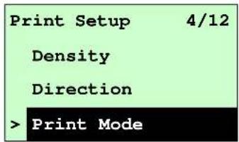
3.1.1.4 Print Mode:(None / Batch Mode / Peeler Mode / Cutter Mode / Cutter Batch)
text_image
Print Setup 4/12 Density Direction > Print Mode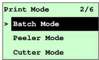
text_image
Print Mode 2/6 > Batch Mode Peeler Mode Cutter ModeThis option is used to set the print mode. Printer default setting is Batch Mode. When enter this list, the print mode in the right side of " >" icon is the printer current setting. Press UP and DOWN to select the different print modes and press the SELECT button to enable the setting. Press key to cancel the setting and return to the previous menu.
| Printer Mode | Description |
| None | Next label top of form is aligned to the print head burn line location. (Tear Off Mode) |
| Batch Mode | Once image is printed completely, label gap/black mark will be fed to the tear plate location for tear away. |
| Peeler Mode | Enable the label peel off mode. |
| Cutter Mode Enable the label cutter mode. |
| Cutter Batch Cut the label once at the end of the printing job. |
Note: If printing from enclosed software/driver, the software/driver will send out the command, which will overwrite the setting set from the front panel.
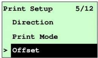
3.1.1.5 Offset:
text_image
Print Setup 5/12 Direction Print Mode > Offset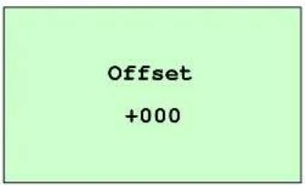
text_image
Offset +000This option is used to fine tune media stop location. Press the DOWN Ⓧ button to move the cursor from left digit to right digit, and press the UP Ⓧ button to set the value from “+” to “-” or “0” to “9”. Press the SELECT button to set the value into printer. Press Ⓞ MENU key to cancel the setting and return to the previous menu. The default value is +000.
Note: If printing from enclosed software/driver, the software/driver will send out the OFFSET command, which will overwrite the setting set from the front panel.
3.1.1.6 Shift X & Shift Y:
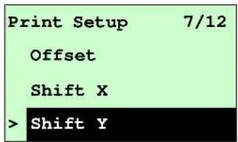
text_image
Print Setup 7/12 Offset Shift X > Shift Y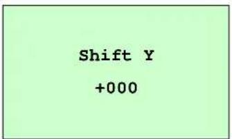
text_image
Shift Y +000This option is used to fine tune print position. Press the DOWN to move the cursor from left digit to right digit, and press the UP button to set the value from "+" to "-" or "0" to "9". Press the SELECT button to set the value into printer. Press MENU key to cancel the setting and return to the previous menu. The default value is +000.
Note: If printing from enclosed software/driver, the software/driver will send out the SHIFT command, which will overwrite the setting set from the front panel.
3.1.1.6 Reference X & Reference Y:
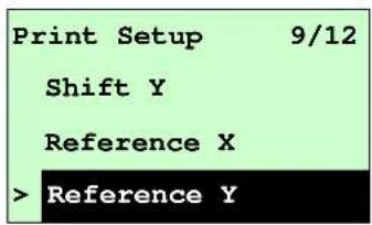
text_image
Print Setup 9/12 Shift Y Reference X > Reference Y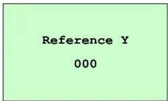
text_image
Reference Y 000This option is used to set the origin of printer coordinate system horizontally and vertically. Press the DOWN button to move the cursor from left digit to right digit, and press the UP button to set the value from "0" to "9". Press the SELECT button to set the value into printer. Press KeyMENancel the setting and return to the previous menu. The default value is 000.
Note: If printing from enclosed software/driver, the software/driver will send out the REFERENCE command, which will overwrite the setting set from the front panel.
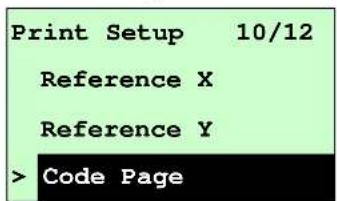
3.1.1.7 Code Page:
text_image
Print Setup 10/12 Reference X Reference Y Code Page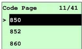
text_image
Code Page 11/41 > 850 852 860Use this option to set the code page of international character set. For more information about code pages, please to refer the programming manual.
When enter the code page list, the code page in the right side of ">” icon is the printer current setting.
Press the UP Ⓧ and DOWN Ⓧ to select the code page, and press the SELECT button to enable the required setting. Press ☐ MENU key to cancel the setting and return to the previous menu.
Note: If printing from enclosed software/driver, the software/driver will send out the command, which will overwrite the setting set from the front panel.
| 7-bit | 8-bit | ||
| code page name | International Character Set | code page number | International Character Set |
| USA | USA | 437 | |
| BRI | British | 850 | Multilingual |
| GER | German | 852 | |
| FRE | French | 860 | |
| DAN | Danish | 863 Canada | |
| ITA | Italian | 865 | Nordic |
United
Sla
Portuguese dian/French
| SPA | Spanish | ||
| SWE | Swedish | ||
| SWI | Swiss |
| Windows Code Page (SBCS) Windows Code Page (DBCS) | |||
| code page number | International Character Set | code page number | International Character Set |
| 1252 Latin 1 | 950 Traditional Chinese Big5 | ||
| 1250 | Central Europe | 936 Simplified | |
| 1253 | Greek | 932 | Japanese Shift-JIS |
| 1254 | Turkish | 949 | Korean |
| 1251 | Cyrillic | ||
| 1255 | Hebrew | ||
| 1256 | Arabic | ||
| 1257 | Baltic | ||
| 1258 | Vietnam | ||
Chinese GBK
| ISO Code Page | ISO Code Page | ||
| code page name | International Character Set | code page number | International Character Set |
| 8859-1 | Latin 1 | 8859-7 | Greek |
| 8859-2 | Latin 2 | 8859-9 | Turkish |
| 8859-3 | Latin 3 | 8859-10 | Latin 6 |
| 8859-4 | Baltic | 8859-15 | Latin 9 |
| 8859-5 | Cyrillic | ||
3.1.1.8 Country:

text_image
Print Setup 11/12 Reference Y Code Page > Country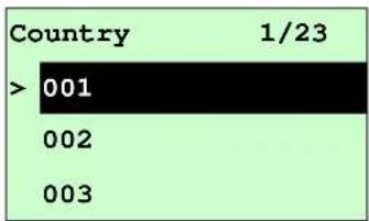
text_image
Country 1/23 > 001 002 003Use this option to set the country code for the LCD display. Press the UP Ⓐ and DOWN Ⓤ to select the country code, and press the SELECT button to set the
value into printer. When enter this list, the country code in the right side of ">" icon is the printer current setting. Press KeyMenu cancel the setting and return to the previous menu.
| Code | Country | Code | Country | Code | Country | Code | Country |
| 001 | USA | 034 | Spanish (Spain) | 044 | United Kingdom | 055 | Brazil |
| 002 | Canadian-French | 036 | Hungarian | 045 | Danish | 061 | English (International) |
| 003 | Spanish (Latin America) | 038 | Yugoslavian | 046 | Swedish | 351 | Portuguese |
| 031 | Dutch | 039 | Italian | 047 | Norwegian | 358 | Finnish |
| 032 | Belgian | 041 | Switzerland | 048 | Polish | ||
| 033 | French (France) | 042 | Slovak | 049 | German |
3.1.2 Sensor

flowchart
graph TD
    A["Sensor"] --> B["..."]
    A --> C["..."]
    A --> D["ExitStatus Calibration"]
3.1.2.1 Status
This function is available to check the printer's sensor status. When enter the [Status] option, you will see following message.
| Paper Len. | 812 |
| Gap Size | 24 |
| Intensity | 3 |
| Ref. Level | 512 |
3.1.2.2 Calibration
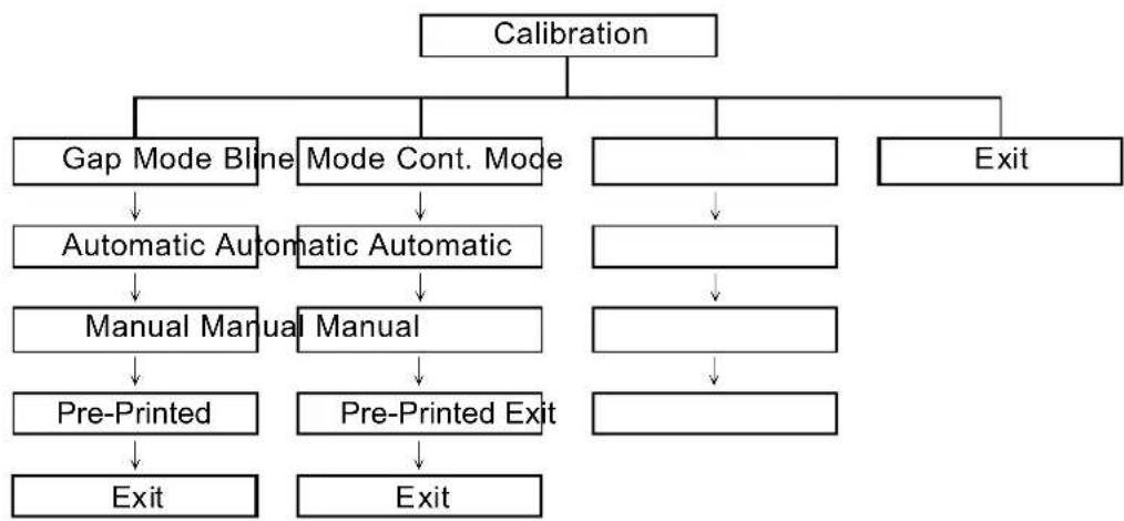
This option is used to set the media sensor type and calibrate the selected sensor. When changing the media, we recommend calibration of the sensor before printing.
flowchart
graph TD
    A["Calibration"] --> B["Gap Mode Blning"]
    A --> C["Mode Cont. Mode"]
    A --> D["Exit"]
    B --> E["Automatic Automatic"]
    C --> F["Automatic Automatic"]
    D --> G["Manual Manual"]
    D --> H["Manual Manual"]
    E --> I["Manual Manual"]
    F --> J["Manual Manual"]
    G --> K["Pre-Printed"]
    H --> L["Pre-Printed Exit"]
    I --> M["Pre-Printed Exit"]
    J --> N["Pre-Printed Exit"]
    K --> O["Exit"]
    L --> P["Exit"]
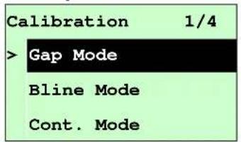
A. Gap Mode
text_image
Calibration 1/4 > Gap Mode Bline Mode Cont. Mode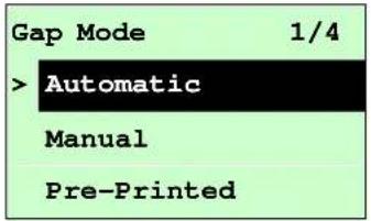
text_image
Gap Mode 1/4 > Automatic Manual Pre-PrintedPress the UP Ⓧ and DOWN Ⓧ buttons to scroll the cursor to the media type and press the SELECT to enter the sensor calibration mode.
Note: If printing from the enclosed software/driver, the software/driver will send out the GAP or BLINE command, which will overwrite the sensor type setting set from the front panel.
A-1 Automatic
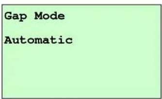
When enter the [Automatic] option, you will see following message, and printer will feed 2 to 3 gap labels to calibrate the sensor sensitivity automatically. When calibration is completed, the LCD screen will return to the previous menu.
text_image
Gap Mode AutomaticA-2 Manual
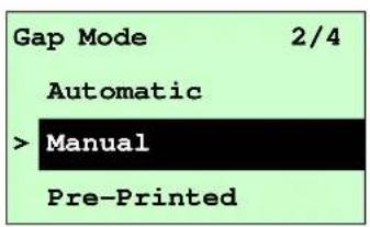
In case “Automatic” sensor calibration cannot apply to the media, please use “Manual” function to calibrate the gap sensor manually.
text_image
Gap Mode 2/4 Automatic > Manual Pre-PrintedWhen enter [Manual] option, you will see following message. Please complete the following steps:
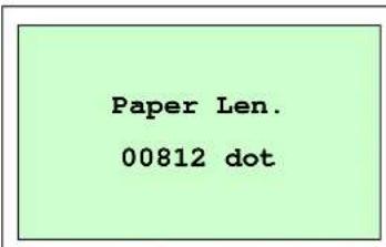
text_image
Paper Len. 00812 dot- Press the DOWN button to move the cursor from left digit to right digit, and press the UP button to set the value from "0" to "9" and the "dot/mm/ inch". Press the SELECT button to set the paper length into the printer.
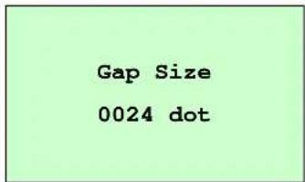 | 2. Press the DOWN button to move the cursor from left digit to right digit, and press the UP button to set the value from “0” to “9” and the “dot/mm/ inch”. Press the SELECT button to set the gap size into the printer. |
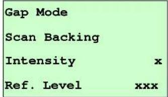 | 3. Open the print head mechanism, put the label backing (liner) under the media sensor. Press the SELECT button to set the value into the printer. |
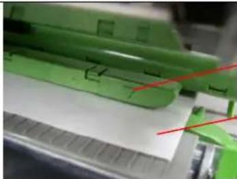 | Media sensorLabel backing (liner) |
 | 4. Then, Put the label with liner under the media sensor. Press the SELECT button to set the value into the printer. |
 | Media sensorLabel with liner |
 | 5. The gap sensor calibration is complete. Press the SELECT button the LCD screen will return to the previous menu. |
A-3 Pre-Printed
This function can set the paper length and gap size before auto-calibrate the sensor sensitivity. It can to get the sensor sensitivity accurately.
| Gap Mode | 3/4 |
| Manual | |
| > Pre-Printed | |
| Exit | |
When enter [Pre-Printed] option, you will see following message. Please complete the following steps steps :
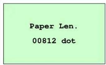 | 1. Press the DOWN button to move the cursor from left digit to right digit, and press the UP button to set the value from “0” to “9” and the “dot/mm/ inch”. Press the SELECT button to set the paper length into the printer. |
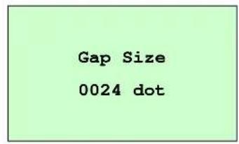 | 2. Press the DOWN button to move the cursor from left digit to right digit, and press the UP button to set the value from “0” to “9” and the “dot/mm/ inch”. Press the SELECT button to set the gap size into the printer. |
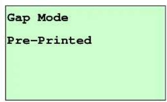 | 3. Then, printer will feed labels to calibrate the sensor sensitivity automatically. When calibration is completed, the LCD screen will return to the previous menu. |
B. Bline Mode
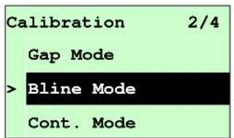
text_image
Calibration 2/4 Gap Mode >B Bline Mode Cont. Mode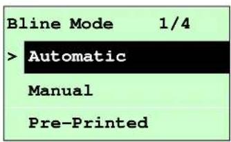
text_image
Bline Mode 1/4 > Automatic Manual Pre-PrintedPress the UP Ⓧ and DOWN Ⓧ buttons to scroll the cursor to the sensor type. Press the SELECT button to enter the black-mark sensor calibration mode.
B-1 Automatic
When enter the [Automatic] option, you will see following message and printer will feed the black mark label to calibrate the sensor sensitivity automatically. When calibration process is completed, the LCD screen will return to the previous menu.
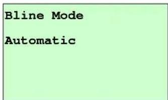
text_image
Bline Mode AutomaticB-2 Manual
In case “Automatic” sensor calibration cannot apply to the media, please use “Manual” function to calibrate the bline sensor manually.
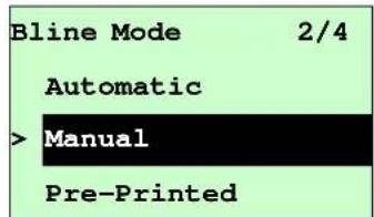
text_image
Bline Mode 2/4 Automatic > Manual Pre-PrintedWhen enter [Manual] option, you will see following message. Please complete the following steps:
| Paper Len. 00151 dot | 1. Press the DOWN button to move the cursor from left digit to right digit, and press the UP button to set the value from "0" to "9" and the "dot/mm/ inch". Press the SELECT button to set the paper length into the printer. |
| Bline Size 0024 dot | 2. Press the DOWN button to move the cursor from left digit to right digit, and press the UP button to set the value from "0" to "9" and the "dot/mm/ inch". Press the SELECT button to set the bline size into the printer. |
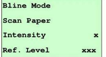
| Bline ModeScan MarkIntensity xRef. Level xxx | 3. Open the print head mechanism put the black mark under the media sensor. Press the SELECT button to set the value into the printer. |
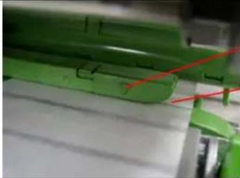 | Media sensorBlack mark |
 | 4. Then, put the label without black mark under the media sensor. Press the SELECT button to set the value into the printer. |
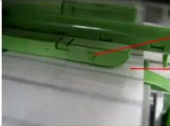 | Media sensorLabel without black mark |
| Note:Normally, the value of “Ref. Level” for mark should be larger than paper for over 128. If the media sensor fails to do so, you have to manually change the Intensity by pressing UP and DOWN to reach the above value. | |
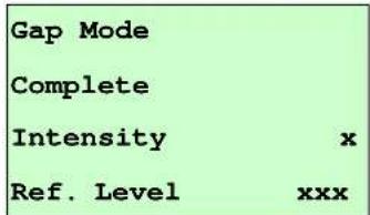
| Bline ModeCompleteIntensity xRef. Level xxx | 5. The bline sensor calibration is complete. Press the SELECT button the LCD screen will return to the previous menu. |
| Bline Mode | |
| Complete | |
| Intensity | x |
| Ref. Level | xxx |
B-3 Pre-Printed
This function can set the paper length and gap size before auto-calibrate the sensor sensitivity. It can to get the sensor sensitivity accurately.
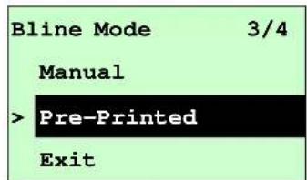
text_image
Bline Mode 3/4 Manual > Pre-Printed ExitWhen enter [Pre-Printed] option, you will see following message. Please
complete there steps :
| Paper Len.00812 dot | 1. Press theDOWN@button to movethe cursor from left digit to right digit,and press theUP Ⓐ button to setthe value from “0” to “9” and the “dot/mm/ inch”. Press theSELECTbutton to set the paper length into the printer. |
| Bline Size0024 dot | 2. Press theDOWN@button to movethe cursor from left digit to right digit,and press theUP Ⓐ button to setthe value from “0” to “9” and the “dot/mm/ inch”. Press theSELECTbutton to set the bline size into the printer. |
| Bline ModePre-Printed | 3. Then, printer will feed labels to calibrate the sensor sensitivity automatically. When calibration is completed, the LCD screen will return to the previous menu. |
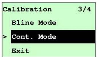
C. Cont. Mode
text_image
Calibration 3/4 Bline Mode > Cont. Mode Exit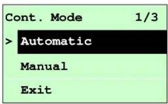
text_image
Cont. Mode 1/3 > Automatic Manual ExitPress the UP Ⓧ and DOWN Ⓧ buttons to scroll the cursor to the sensor type. Press the SELECT button to enter the black-mark sensor calibration mode.
C-1 Automatic
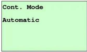
When enter the [Automatic] option, you will see following message and printer will calibrate the sensor sensitivity automatically. When calibration process is completed, the LCD screen will return to the previous menu.
text_image
Cont. Mode AutomaticC-2 Manual
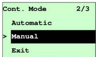
In case “Automatic” sensor calibration cannot apply to the media, please use “Manual” function to calibrate the sensor manually.
text_image
Cont. Mode 2/3 Automatic > Manual ExitWhen enter [Manual] option, you will see following message. Please complete the following steps :
| Cont. ModeRemove LabelIntensity xRef. Level xxx | 1. Remove the continuous label. Press the SELECT button to set the value into the printer. |
| Cont. ModeScan PaperIntensity xRef. Level xxx | 2. Then, put the continuous label under the media sensor. Press the SELECT button to set the value into the printer. |
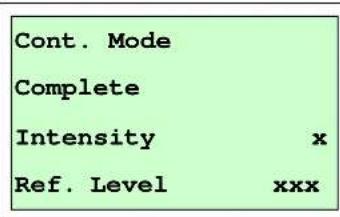
text_image
Cont. Mode Complete Intensity x Ref. Level xxx- The sensor calibration is complete. Press the SELECT button the LCD screen will return to the previous menu.
3.1.3 Serial Comm.
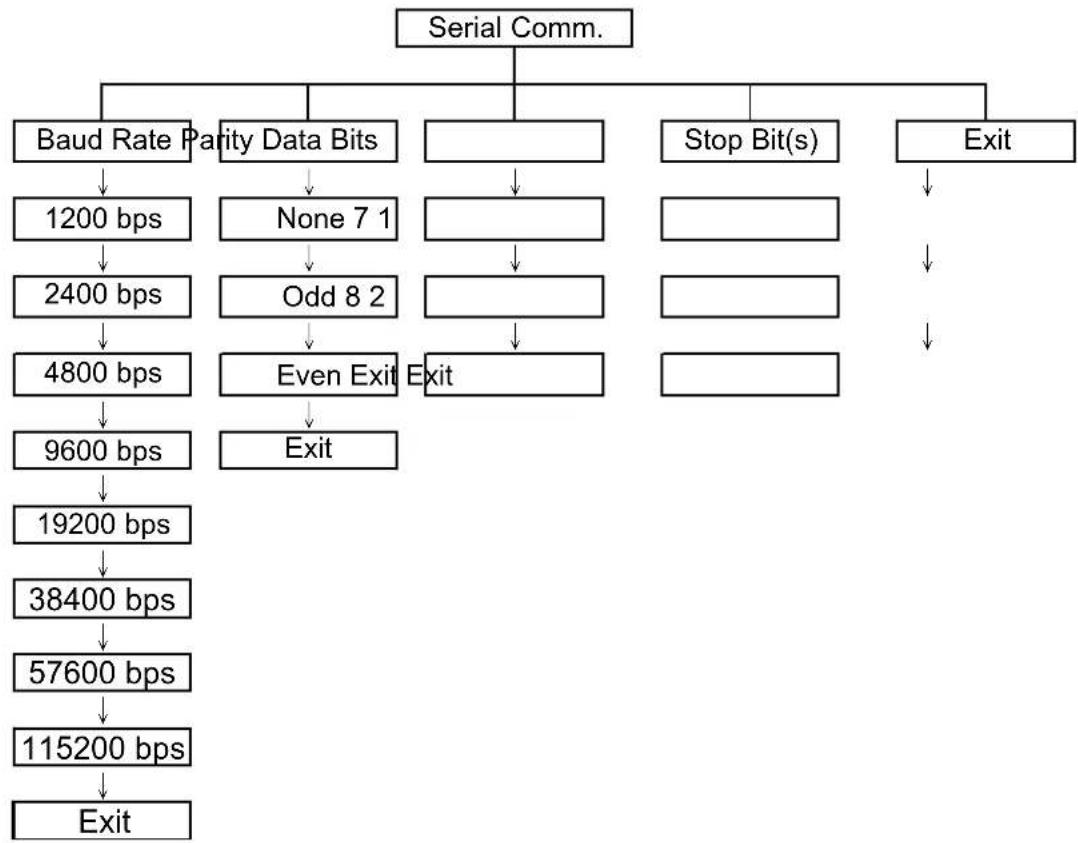
flowchart
graph TD
    A["Serial Comm."] --> B["Baud Rate"]
    A --> C["Parity Data Bits"]
    A --> D[" "]
    A --> E["Stop Bit(s)"]
    A --> F["Exit"]
    B --> G["1200 bps"]
    C --> H["None 7 1"]
    D --> I[" "]
    E --> J[" "]
    F --> K[" "]
    G --> L["2400 bps"]
    H --> M["Odd 8 2"]
    I --> N[" "]
    J --> O[" "]
    K --> P[" "]
    L --> Q["4800 bps"]
    M --> R["Even Exit"]
    N --> S["Exit"]
    Q --> T["9600 bps"]
    R --> U["Exit"]
    S --> V["19200 bps"]
    T --> W["38400 bps"]
    U --> X["57600 bps"]
    V --> Y["115200 bps"]
    W --> Z["Exit"]
3.1.3.1 Baud Rate
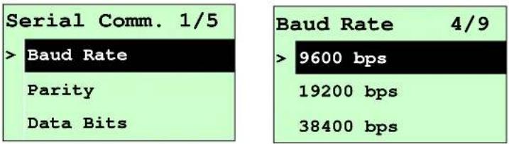
text_image
Serial Comm. 1/5 >Baud Rate Parity Data Bits Baud Rate 4/9 >9600 bps 19200 bps 38400 bpsThis option is used to set the RS-232 baud rate. The default setting is 9600 bps. Press UP Ⓧ and DOWN Ⓧ buttons to select the different baud rate and press SELECT button to set the value into printer. When you enter this list, the baud rate value in the right side of ">” icon is the current setting in the printer. Press ☐ MENU key to cancel the setting and return to the previous menu.
3.1.3.2 Parity
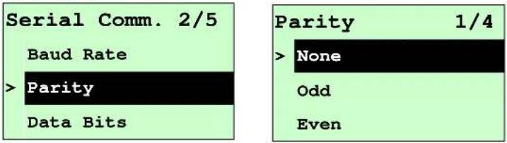
text_image
Serial Comm. 2/5 Baud Rate > Parity Data Bits Parity 1/4 > None Odd EvenThis option is used to set the RS-232 parity. The default setting is "None". Press UP Ⓧ and DOWN Ⓧs to select the different parity and press SELECT button to set the value into printer. When you enter this list, the parity in the right side of ">” is the printer current setting. Press ☐ MENU key to cancel the setting and return to the previous menu.
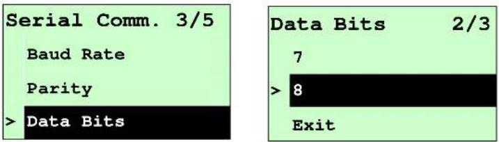
3.1.3.3 Data Bits:
text_image
Serial Comm. 3/5 Baud Rate Parity > Data Bits Data Bits 2/3 7 > 8 ExitThis option is used to set the RS-232 Data Bits. The default setting is "8" data bits. Press UP Ⓧ and DOWN Ⓧ buttons to select the different Data Bits and press SELECT button to set the value into printer. When you enter this list, the Data Bits in the right side of ">” icon is the printer current setting. Press ☐ MENU key to cancel the setting and return to the previous menu.
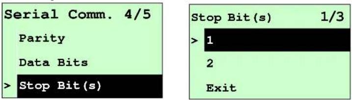
3.1.3.4 Stop Bit(s):
text_image
Serial Comm. 4/5 Parity Data Bits > Stop Bit(s) Stop Bit(s) 1/3 > 1 2 ExitThis option is used to set the RS-232 Stop Bits. The default setting is "1" stop bit. Press UP Ⓧ and DOWN Ⓧ buttons to select the different Stop Bits and press SELECT button to set the value into printer. When you enter this list, the option in the right side of ">” icon is the printer current setting. Press ☐ MENU key to cancel the setting and return to the previous menu.
3.1.4 Ethernet
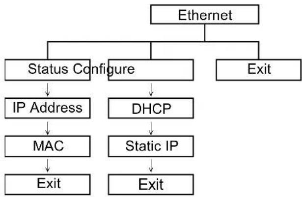
Use this menu to configure internal Ethernet configuration check the printer's Ethernet module status, and reset the Ethernet module. This function is available on the LCD display when Ethernet card is installed.
Press UP Ⓧ and DOWN Ⓧ buttons to select the different options and press the SELECT button to enter the option. Press ⏚key MENSancel the setting and return to the previous menu.
flowchart
graph TD
    A["Ethernet"] --> B["Status Configure"]
    A --> C["Exit"]
    B --> D["IP Address"]
    B --> E["DHCP"]
    D --> F["MAC"]
    F --> G["Exit"]
    E --> H["Static IP"]
    H --> I["Exit"]
Note:
This function is available for M4210/M4306/T-0612/T-0613 series only and option for M-2406 Plus/M-3406 Plus/T-462 Plus/T-443 Plus series.
3.1.4.1 Status: (IP Address / MAC)
Use this menu to check the Ethernet setting status.
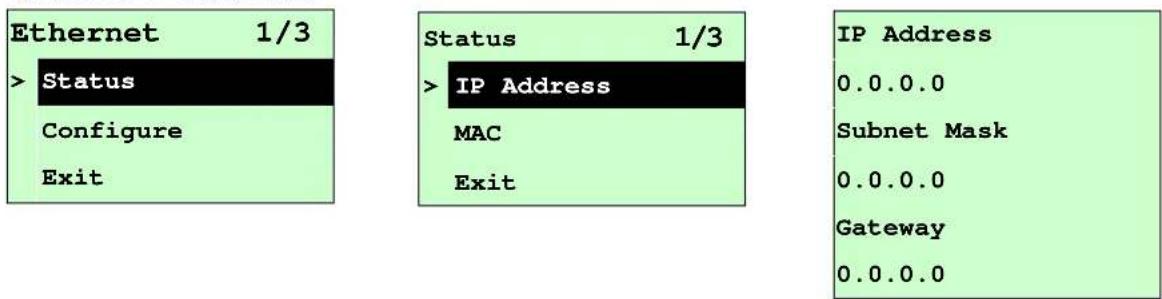
3.1.4.1.1 IP Address
text_image
Ethernet 1/3 > Status Configure Exit Status 1/3 > IP Address MAC Exit IP Address 0.0.0.0 Subnet Mask 0.0.0.0 Gateway 0.0.0.0The IP address information will be shown on the LCD display. Please press SELECT or □MENU to return to the previous menu.
3.1.4.1.2 MAC
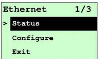
text_image
Ethernet 1/3 > Status Configure Exit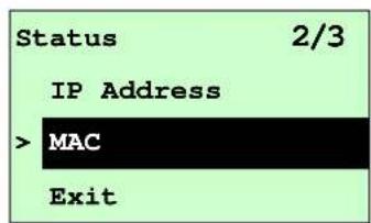
text_image
Status 2/3 IP Address > MAC Exit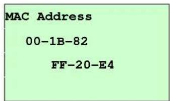
text_image
MAC Address 00-1B-82 FF-20-E4The MAC address information will be shown on the LCD display. Please press SELECT or ☐MENU to return to the previous menu.
3.1.4.2 Configure: (DHCP / Static IP)
Use this menu to set the printer's DHCP and Static IP.
3.1.4.2.1 DHCP
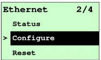
text_image
Ethernet 2/4 Status > Configure Reset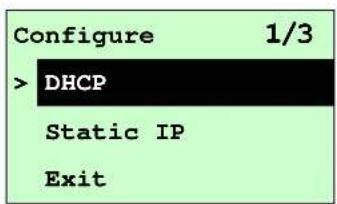
text_image
Configure 1/3 > DHCP Static IP ExitPress UP and DOWN buttons to select the DHCP function and press SELECT to enter. Press keyMenu cancel the setting and return to the previous menu.

text_image
DHCP SELECT: YES MENU: NOPress SELECT button the printer will set DHCP and restart to reset the setting. Press ■sumENo return to the previous menu.
3.1.4.2.2 Static IP
Use this menu to set the printer's IP address, subnet mask and gateway.
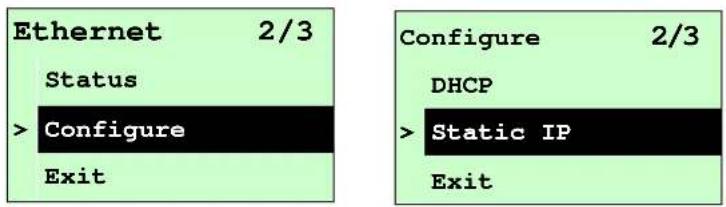
text_image
Ethernet 2/3 Status > Configure Exit Configure 2/3 DHCP > Static IP ExitPress UP Ⓧ and DOWN Ⓧ buttons to select the different options and press SELECT button to enter the option. Press ⏱ MENU key to cancel the setting and return to the previous menu.
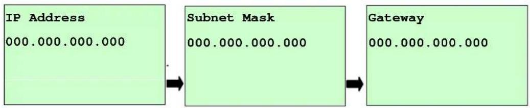
flowchart
graph LR
    A["IP Address\n000.000.000.000"] --> B["Subnet Mask\n000.000.000.000"]
    B --> C["Gateway\n000.000.000.000"]
Press DOWN ☑ to move the cursor from left to right digits and press the UP Ⓧ button to scroll the value from "0" to "9". Press SELECT button to next setting.
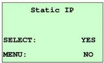
text_image
Static IP SELECT: YES MENU: NOPress the SELECT button printer will restart to reset the Ethernet module setting. Press keyMenu cancel the setting.
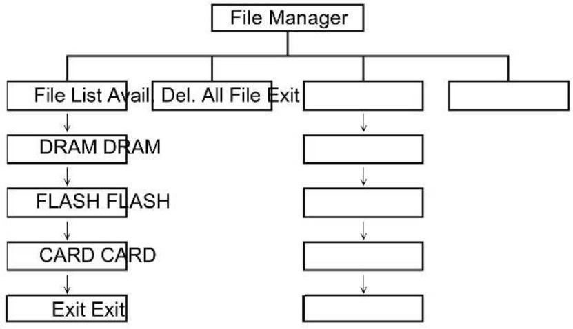
3.2 File Manager
This feature is used to check the printer available memory and file list.
flowchart
graph TD
    A["File Manager"] --> B["File List Avail"]
    A --> C["Del. All File Exit"]
    B --> D["DRAM DRAM"]
    D --> E["FLASH FLASH"]
    E --> F["CARD CARD"]
    F --> G["Exit Exit"]
    C --> H[" "]
    H --> I[" "]
    I --> J[" "]
    J --> K[" "]
3.2.1 File List
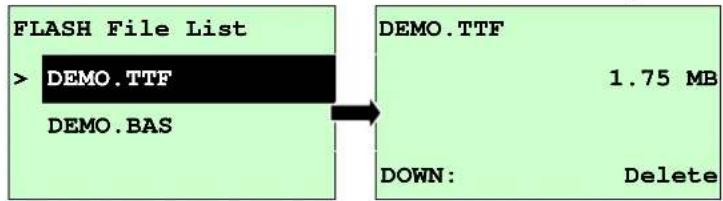
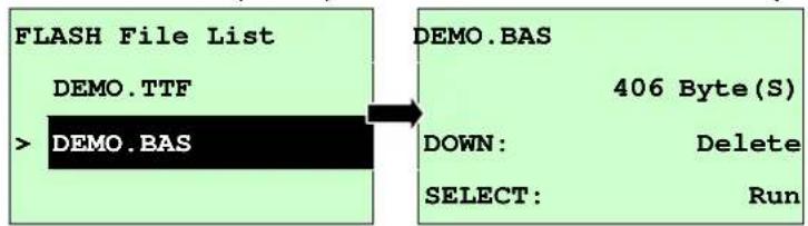
Use this menu to show, delete and run (.BAS) the files saved in the printer DRAM/Flash/Card memory.
To show the files :

text_image
File Manager 1/4 > File List Avail. Memory Del. All Files File List 2/4 > FLASH CARD Exit FLASH File List > DEMO.TTF DEMO.BASTo delete the file : Please follow the order to press the DOWN ⬤ button.
flowchart
graph LR
    A["FLASH File List"] --> B["DEMO.TTF"]
    A --> C["DEMO.BAS"]
    B --> D["1.75 MB"]
    C --> E["DOWN: Delete"]
To run the file (.BAS) : Please follow the order to press the SELECT button.
flowchart
graph LR
    A["FLASH File List"] --> B["DEMO.TTF"]
    B --> C["> DEMO.BAS"]
    C --> D["DEMO.BAS"]
    D --> E["DOWN: Delete"]
    D --> F["SELECT: Run"]
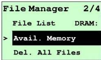
3.2.2 Avail. Memory
Use this menu to show available memory space.
text_image
File Manager 2/4 File List DRAM: > Avail. Memory Del. All Files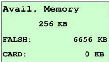
text_image
Avail. Memory 256 KB FALSH: 6656 KB CARD: 0 KB3.2.3 Del. All Files
Use this menu to delete all files. Press SELECT button to delete all files in the device. Press ☐ MENU to cancel deleting files and go back to previous menu.
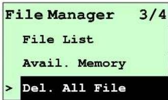
text_image
File Manager 3/4 File List Avail. Memory > Del. All File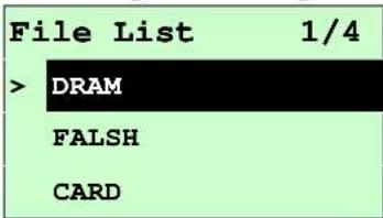
text_image
File List 1/4 > DRAM FALSH CARD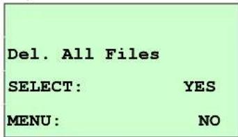
text_image
Del. All Files SELECT: YES MENU: NO3.3 Diagnostics

flowchart
graph TD
    A["De Diagnostics"] --> B["Diagnosis"]
    A --> C["ExitPrint Config. Dump Mode Rotate"]
    B --> D["Diagnosis"]
    B --> E["ExitPrint Config. Dump Mode Rotate"]
3.3.1 Print Configuration.
This feature is used to print current printer configuration to the label. On the configuration printout, there is a print head test pattern, which is useful for checking if there is any dot damage on the print head heater element.

text_image
Diagnostics 1/4 > Print Config. Dump Mode Rotate Cutter Self Test ... Printing ... 1/1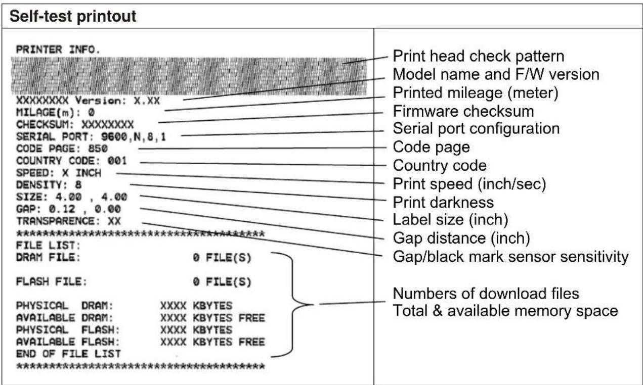
text_image
Self-test printout PRINTER INFO. XXXXXXX Version: X.XX MILAGE(m): 0 CHECKSUM: XXXXXXXX SERIAL PORT: 9600,N,8,1 CODE PAGE: 850 COUNTRY CODE: 001 SPEED: X INCH DENSITY: 8 SIZE: 4.00 , 4.00 GAP: 0.12 , 0.00 TRANSPARENCE: XX ****************** FILE LIST: DRAM FILE: 0 FILE(S) FLASH FILE: 0 FILE(S) PHYSICAL DRAM: XXXX KBYTES AVAILABLE DRAM: XXXX KBYTES FREE PHYSICAL FLASH: XXXX KBYTES AVAILABLE FLASH: XXXX KBYTES FREE END OF FILE LIST ******************3.3.2 Dump Mode
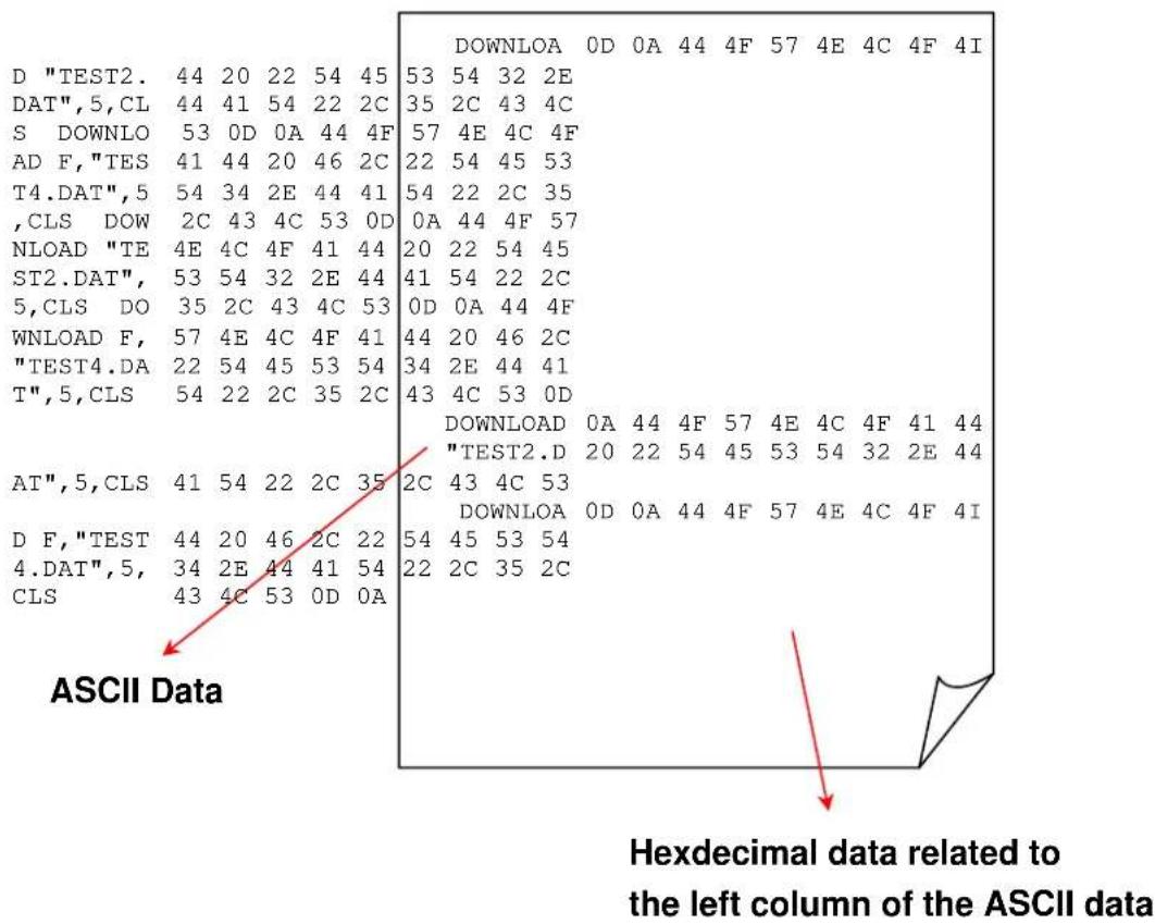
Captures the data from the communications port and prints out the data received by printer. In the dump mode, all characters will be printed in 2 columns as following. The left side characters are received from your system and right side data are the corresponding hexadecimal value of the characters. It allows users or engineers to verify and debug the program.

flowchart
graph LR
    A["Diagnostics 2/4"] --> B["Pritn Config. 1/1"]
    B --> C["Dump Mode"]
    C --> D["Rotate cutter"]
    E["Printing ... Dump Mode"] --> F
Note:
- Dump mode requires 4" wide paper width.
- Turn off / on the power to resume printer for normal printing.
- Press FEED button to back to the previous menu.
text_image
D "TEST2. 44 20 22 54 45 53 54 32 2E DAT",5,CL 44 41 54 22 2C 35 2C 43 4C S DOWNLO 53 0D 0A 44 4F 57 4E 4C 4F AD F,"TES 41 44 20 46 2C 22 54 45 53 T4.DAT",5 54 34 2E 44 41 54 22 2C 35 ,CLS DOW 2C 43 4C 53 0D 0A 44 4F 57 NLOAD "TE 4E 4C 4F 41 44 20 22 54 45 ST2.DAT", 53 54 32 2E 44 41 54 22 2C 5,CLS DO 35 2C 43 4C 53 0D 0A 44 4F WNLOAD F, 57 4E 4C 4F 41 44 20 46 2C "TEST4.DA 22 54 45 53 54 34 2E 44 41 T",5,CLS 54 22 2C 35 2C 43 4C 53 0D DOWNLOAD 0A 44 4F 57 4E 4C 4F 41 44 "TEST2.D" 20 22 54 45 53 54 32 2E 44 AT",5,CLS 41 54 22 2C 35 2C 43 4C 53 D F,"TEST 44 20 46 2C 22 54 45 53 54 D.DAT",5, CLS:34,2E,44,41,54,22,2C,35,2C DOWNLOAD:0D:0A:0A:0A:0A:0A:0A:0A:0A:0A:0A:0A:0A:0A:0A:0A:0A:0A:0A:0A:0A:0A:0A:0A:0A:0A:0A:0A:0A:0A:0A:0A:0A:0A:0A: Hexdecimal data related to the left column of the ASCII data3.3.3 Rotate Cutter
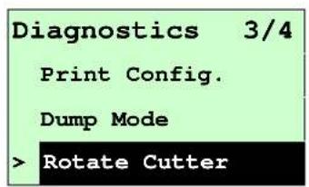
In case paper is jammed in the cutter, this feature can rotate the cutter blade forward or reverse direction, which is helpful to remove the jammed paper easily from the cutter.
text_image
Diagnostics 3/4 Print Config. Dump Mode > Rotate Cutter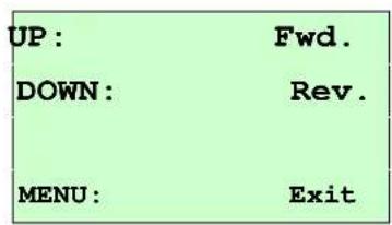
text_image
UP: DOWN: MENU: Fwd. Rev. Exit3.4 Language

flowchart
graph TD
    A["Language"] --> B["English"]
    A --> C["Chinese (TC)"]
    A --> D["Chinese (SC)"]
    A --> E["Japanes"]
    A --> F["German"]
    A --> G["Italian"]
    A --> H["French"]
    A --> I["Russian"]
    A --> J["Polish"]
    A --> K["Spanish"]
    A --> L["Exit"]
This option is used to setup the language on LCD display.
Press UP Ⓧ and DOWN Ⓧ buttons to scroll the curser to desire language and press SELECT button to select this option. Press ⏱ MENU key to cancel the setting and return to the previous menu. The default language setting is English.
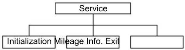
3.5 Service
flowchart
graph TD
    A["Service"] --> B["Initialization"]
    A --> C["Mileage Info. Exit"]
    A --> D["End"]
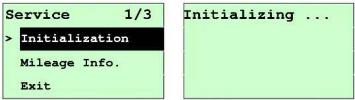
This feature is used to restore printer settings to defaults and display printer mileage information.
3.5.1 Initialization
text_image
Service 1/3 > Initialization Mileage Info. Exit Initializing ...The printer settings are restored to defaults as below once printer is initialized.
Note :
When printer initialization is done, please calibrate the gap or black mark sensor before printing.
| Parameter Default setting | ||
| Speed | K4710 6 IPS (152 mm/sec) | |
| K4730 4 IPS (101.6 mm/sec) | ||
| K4760 3 IPS (76.2 mm/sec) | ||
| Density | 8 | |
| Label width | 4.00"(101.6mm) | |
| Label height | 4.00"(101.6mm) | |
| Sensor type | Gap sensor | |
| Gap setting | 0.12"(3.0mm) | |
| Print direction | 0 | |
| Reference point | 0,0(upper left corner) | |
| Offset | 0 | |
| Print mode | Batch mode | |
| Serial port settings | 9600 bps, none parity, 8 data bits, 1 stop bit | |
| Code page | 850 | |
| Country code | 001 | |
| Clear flash memory | No | |
| Shift X | 0 | |
| Shift Y | 0 | |
| Gap sensor sensitivity | 3 (Will be reset. Need to re-calibrate the gap) | |
| Bline sensor sensitivity | 2 (Will be reset. Need to re-calibrate the gap) | |
| Language | English | |
| IP address | DHCP | |
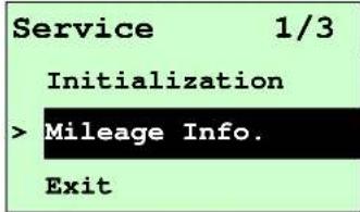
3.5.2 Mileage Info.
Use this option to check the printed mileage (displayed in metres).
text_image
Service 1/3 Initialization >Mileage Info. Exit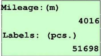
text_image
Mileage: (m) 4016 Labels: (pcs.) 516984. Diagnostic Tool
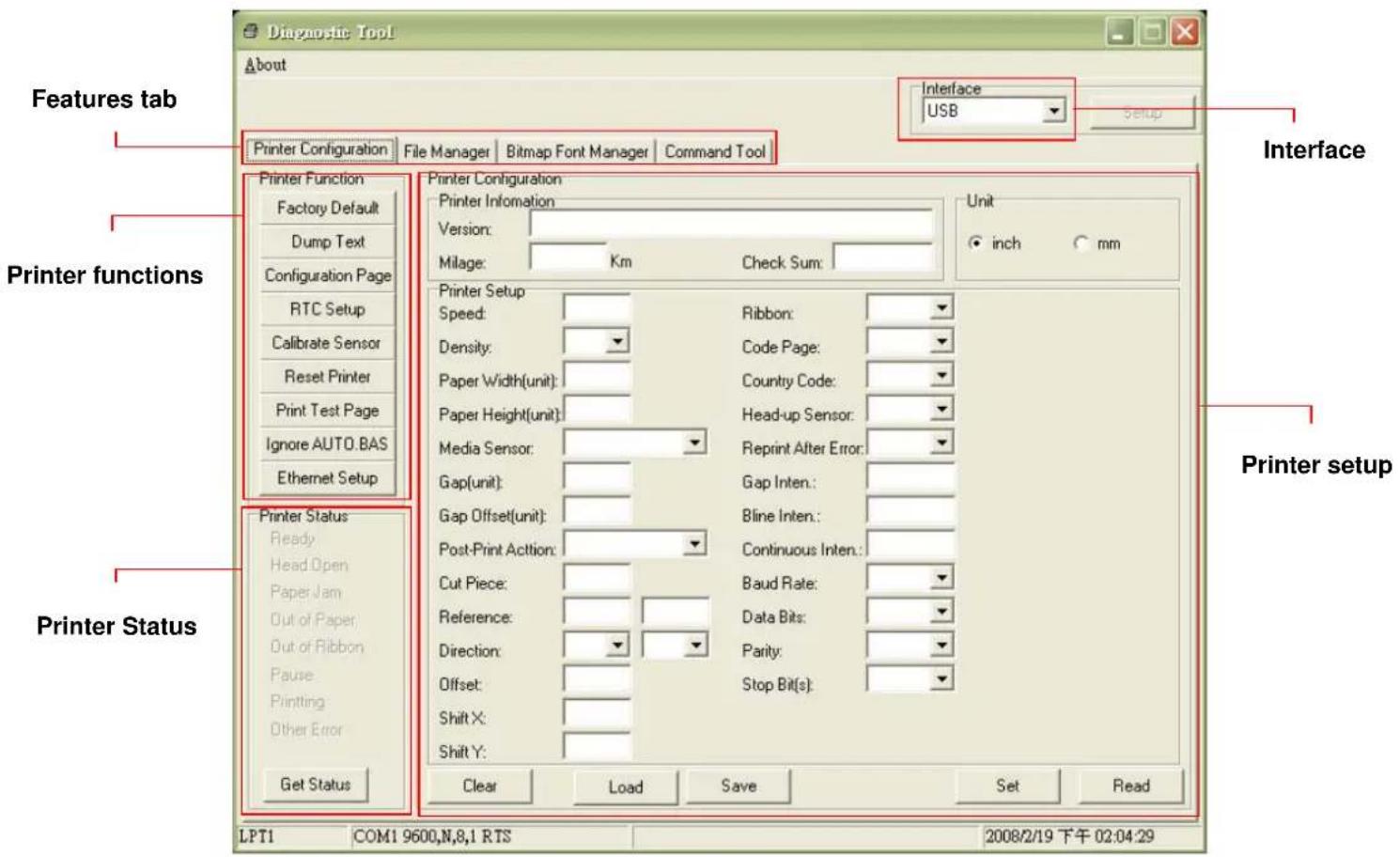
The Diagnostic Utility is a toolbox that allows users to explore the printer's settings and status; change printer settings; download graphics, fonts, and firmware; create printer bitmap fonts; and to send additional commands to the printer. Using this convenient tool, you can explore the printer status and settings and troubleshoot the printer.
Note: This utility works with printer firmware V6.00 and later versions.
4.1 Start the Diagnostic Tool
- Double click on the Diagnostic tool icon

DiagTool.exe
- There are four features (Printer Configuration, File Manager, Bitmap Font Manager, Command Tool) included in the Diagnostic utility.
text_image
Diagnostic Tool About Interface USB Setup Features tab Printer Configuration File Manager Bitmap Font Manager Command Tool Printer Function Factory Default Dump Text Configuration Page RTC Setup Calibrate Sensor Reset Printer Print Test Page Ignore AUTO.BAS Ethernet Setup Printer Status Ready Head.Open Paper Jam Out of Paper Out of Ribbon Pause Printing Other Error Get Status Printer Configuration Printer Information Version: Milage: Km Check Sum: Unit inch mm Printer Setup Speed: Density: Paper Width(unit): Paper Height(unit): Media Sensor: Gap(unit): Gap Offset(unit): Post-Print Action: Cut Piece: Reference: Direction: Offset: Shift X: Shift Y: Ribbon: Code Page: Country Code: Head-up Sensor: Reprint After Error: Gap Inten:: Bline Inten:: Continuous Inten:: Baud Rate: Data Bits: Parity: Stop Bit(s): Printer setup Printer status LPT1 COM1 9600,N,8,1 RTS 2008/2/19 下午 02:04:294.2 Printer Function (Calibrate sensor, Ethernet setup, RTC setup.....)
- Select the PC interface connected with bar code printer.
- Click the "Function" button to setting.
- The detail functions in the Printer Function Group are listed as below.
| Printer FunctionFactory DefaultDump TextConfiguration PageRTC SetupCalibrate SensorReset PrinterPrint Test PageIgnore AUTO.BASEthernet Setup | Function Description | |
| Factory Default | Initialize the printer and restore the settings to factory default. | |
| Dump Text To activate | the printer dump mode. | |
| Configuration Page Print printer configuration. | ||
| RTC Setup Synchronize printer Real Time Clock with PC. | ||
| Calibrate Sensor | Calibrate the sensor specified in the Printer Setup group media sensor field. | |
| Reset Printer Reboot the printer. | ||
| Print Test Page Print a test page. | ||
| Ignore AUTO.BAS Ignore the downloaded AUTO.BAS program. | ||
| Ethernet Setup | Setup the IP address, subnet mask, gateway for the on board Ethernet. | |
Note:
For more information about Diagnostic Tool, please refer to the diagnostic utility quick start guide in the CD disk \ Utilities directory.
5. Troubleshooting
5.1 Common Problems
The following guide lists the most common problems that may be encountered when operating this bar code printer. If the printer still does not function after all suggested solutions have been invoked, please contact the Customer Service Department of your purchased reseller or distributor for assistance.
| Problem Possible Cause Recovery Procedure | ||
| Power indicator does not illuminate | * The power cord is not properly connected. | * Plug the power cord in printer and outlet.* Switch the printer on. |
| Carriage Open | * The printer carriage is open. * Please close the print carriage. | |
| No Ribbon | * Running out of ribbon.* The ribbon is installed incorrectly. | * Supply a new ribbon roll.* Please refer to the steps in user's manual to reinstall the ribbon. |
| No Paper | * Running out of label.* The label is installed incorrectly.* Gap/black mark sensor is not calibrated. | * Supply a new label roll.* Please refer to the steps in user's manual to reinstall the label roll.* Calibrate the gap/black mark sensor. |
| Paper Jam | * Gap/black mark sensor is not set properly.* Make sure label size is set properly.* Labels may be stuck inside the printer mechanism. | * Calibrate the gap/black mark sensor.* Set label size correctly. |
| Take Label | * Peel function is enabled. | * If the peeler module is installed, please remove the label.* If there is no peeler module in front of the printer, please switch off the printer and install it.* Check if the connector is plugging correctly. |
| UP: Fwd.DOWN: Rev elevated: Exit | * Cutter jam.* There is no cutter installed on the printer.* Cutter PCB is damaged. | * If the cutter module is installed, please press UP or DOWN key to rotate the cutter up or down to make the knife back to the right position.* Remove the label.* Make sure the thickness of label is less than 200 g/m2 (for regular cutter) or 300 g/m2 (for heavy duty cutter).* Replace a cutter PCB. |
| Not Printing | * Cable is not well connected to serial or USB interface or parallel port.* The serial port cable pin configuration is not pin to pin connected. | * Re-connect cable to interface.* If using serial cable,- Please replace the cable with pin to pin connected.- Check the baud rate setting. The default baud rate setting of printer is 9600,n,8,1.* If using the Ethernet cable,- Check if the Ethernet RJ-45 connector green LED is lit on..- Check if the Ethernet RJ-45 connector amber LED is blinking.- Check if the printer gets the IP address when using DHCP mode.- Check if the IP address is correct when using the static IP address.- Wait a few seconds let the printer get the communication with the server then check the IP address setting again.* Chang a new cable.* Ribbon and media are not compatible.* Verify the ribbon-inked side.* Reload the ribbon again.* Clean the printhead.* The print density setting is incorrect.* Printhead's harness connector is not well connected with the printhead. Turn off the printer and plug the connector again.* Check if the stepping motor is plugging in the right connector.* Check your program if there is a command PRINT at the end of the file and there must have CRLF at the end of each command line. |
| Memory full( FLASH / DRAM ) | * The space of FLASH/DRAM is full. | * Delete unused files in the FLASH/DRAM.* The max. number of files of DRAM is 50 files for K4652NB/K4653NB and 256 files for K4710/K4730.* The max. user addressable memory space of DRAM is 256 KB for K4652NB/K4653NB and 2048KB for K4710/K4730.* The max. number of files of FLASH is 256 files.* The max. user addressable memory space of FLASH is 2560 KB for K4652NB/K4653NB and 6656KB for K4710/K4730. |
| SD card is unable to use | * SD card is damaged.* SD card doesn't insert correctly.* Use the non-approved SD card manufacturer. | * Use the supported capacity SD card.* Insert the SD card again.* The supported SD card spec and the approved SD card manufacturers, please refer to 2.2.3 section. |
| PS/2 port does not work | * Did not turn off power prior to plug in the PS/2 keyboard.* PS/2 keyboard is damaged.* PS/2 keyboard doesn't plug-in correctly.* There is no BAS file in the printer. | * Turn off printer power prior to plug in the PS/2 keyboard.* Plug the PS/2 keyboard again.* Make sure the keyboard is fine.* Make sure if there is any BAS file downloaded into printer. |
| Poor Print Quality | * Ribbon and media is loaded incorrectly* Dust or adhesive accumulation on the print head.* Print density is not set properly.* Printhead element is damaged.* Ribbon and media are incompatible.* The printhead pressure is not set properly. | * Reload the supply.* Clean the printhead.* Clean the platen roller.* Adjust the print density and print speed.* Run printer self-test and check the print head test pattern if there is dot missing in the pattern.* Change proper ribbon or proper label media.* Adjust the printhead pressure adjustment knob.- If the left side printout is too light, please adjust the left side pressure adjustment knob to the higher index (higher pressure). If the pressure adjustment knob has been adjust to index “5” and the poor print quality is still at the left side of the printout, please adjust the pressure adjustment knob to index “1” and use the Z-axis adjustment knob to fine tune the pressure.- If the right side printout is too light, please adjust the right side pressure adjustment knob to the higher index (higher pressure) to improve the print quality.* If the label thickness is more than 0.22 mm, the print quality might be not good enough, please adjust the heater line adjustment screw counter clockwise to get the best print quality.* The release lever does not latch the printhead properly. |
| LCD panel is dark and keys are not working | * The cable between main PCB and LCD panel is loose. | * Check if the cable between main PCB and LCD is secured or not. |
| LCD panel is dark but the LEDs are light | * The printer initialization is unsuccessful. | * Turn OFF and ON the printer again.* Initialize the printer. |
| LCD panel is dark and LEDs are lit on, but the label is feeding forward | * The LCD panel harness connector is loose. | * The LCD panel harness connector is plugged upside down. |
| Ribbon encoder sensor doesn’t work | * The ribbon encoder sensor connector is loose. | * Fasten the connector. |
| Ribbon end sensor doesn’t work | * The connector is loose.* The ribbon sensor hole is covered with dust. | * Check the connector.* Clear the dust in the sensor hole by the blower. |
| Peel sensor is not working | * Peel sensor is not located on the correct position.* The connector is loose. | * Make sure that the media goes through the Peel sensor.* Plug the connect cable correctly. |
| Cutter is not working | * The connector is loose. * Plug in the connect cable correctly. | |
| Label feeding is not stable (skew) when printing | * The media guide does not touch the edge of the media. | * If the label is moving to the right side, please move the label guide to left.* If the label is moving to the left side, please move the label guide to right. |
| Skip labels when printing | * Label size is not specified properly.* Sensor sensitivity is not set properly.* The media sensor is covered with dust. | * Check if label size is setup correctly.* Calibrate the sensor by Auto Gap or Manual Gap options.* Clear the GAP/Black mark sensor by blower. |
| The printing position of small label is incorrect | * Media sensor sensitivity is not set properly.* Label size is incorrect.* The parameter Shift Y in the LCD menu is incorrect.* The vertical offset setting in the driver is incorrect. | * Calibrate the sensor sensitivity again.* Set the correct label size and gap size.* Press [MENU] → [SELECT] x3→[DOWN]x6 → [SELECT] to fine tune the parameter of Shift Y.* If using the software BarTender, please set the vertical offset in the driver.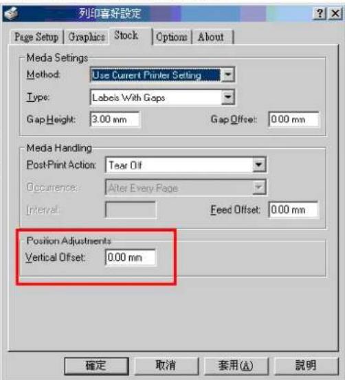 |
| The left side printout position is incorrect | * Wrong label size setup.* The parameter Shift X in LCD menu is incorrect. | * Set the correct label size.* Press [MENU] → [SELECT] x 3 → [DOWN] x 5 → [SELECT] to fine tune the parameter of Shift X. |
| Missing printing on the left or right side of label | * Wrong label size setup. * Set the correct label size. | |
| RTC time is incorrect when reboot the printer | * The battery has run down. * Check if there is a battery on the main board. | |
| Multi interface board doesn't work | * The installation is incorrect. | * Check if the board is plugged in the right connector. |
| Power and Error LEDs are blinking fast | * Power switch OFF and ON too fast. | * Turn off the printer and wait all LEDs are dark, and turn on the printer again. |
| Wrinkle Problem | * Printhead pressure is incorrect.* Ribbon installation is incorrect.* Media installation is incorrect.* Print density is incorrect.* Media feeding is incorrect. | * Please refer to the 5.2 chapter.* Please set the suitable density to have good print quality.* Make sure the label guide touch the edge of the media guide. |
| Gray line on the blank label | * The printhead is dirty.* The platen roller is dirty. | * Clean the printhead.* Clean the platen roller. |
| Irregular printing | * The printer is in Hex Dump mode.* The RS-232 setting is incorrect. | * Turn off and on the printer to skip the dump mode.* Re-set the Rs-232 setting. |
5.2 Mechanism Fine Adjustment to Avoid Ribbon Wrinkles
This printer has been fully tested before delivery. There should be no ribbon wrinkle presented on the media for general-purpose printing application. Ribbon wrinkle is related to the media thickness, print head pressure balance, ribbon film characteristics, print darkness setting...etc. In case the ribbon wrinkle happens, please follow the instructions below to adjust the printer parts.
| Adjustable Printer Parts | Print head pressure adjustment knob | 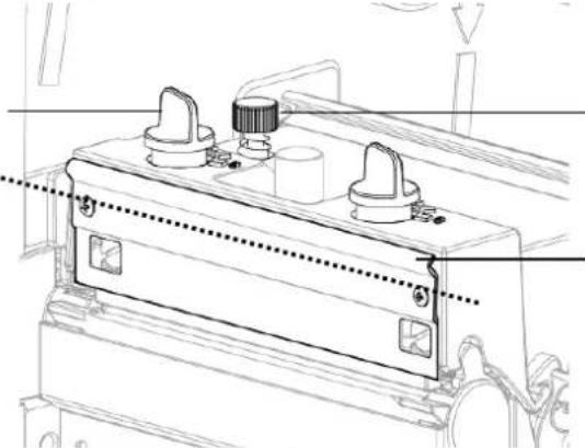 | Z-axis mechanism adjustment knobRibbon guide plate |
| Symptom | 1. Wrinkle happens from label lower left to upper right direction (" ' ") | 2. Wrinkle happens from label lower right to upper left direction (" ' ") | |
| Wrinkle Example |  |  Feed direction Feed direction |  |
Adjust the print head pressure adjustment knob
text_image
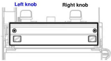
Left knob Right knobThe print head pressure adjustment knob has 5 levels of settings. Clockwise direction adjustment is to increase the print head pressure. Counter Clockwise adjustment can decrease the print head pressure.
If the wrinkle on the label starts from the lower left side to upper right side, please do following adjustment.
- Decrease the right side print head pressure adjustment knob setting 1 level per each adjustment then print the label again to check if wrinkle is gone.
- If the right side print head adjustment knob setting has been set to index 1 (the lowest pressure index), please increase the left side print head pressure.
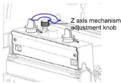
- If the left side print head adjustment knob setting has been set to 5 (the highest pressure index) the wrinkle can't be avoid, please rotate the both knobs back to setting 1 then rotate the Z-axis mechanism adjustment knob clockwise for a few degrees and print again for fine tune the print head pressure distribution.
text_image
Z axis mechanism adjustment knobNote for step 3:
*Factory default setting, the Z-axis knob is rotated counter clockwise to the end of thread.
*Turn the Z-axis mechanism adjustment knob clockwise until you feel the knob touch the mechanism for the first adjustment.
* If the wrinkle is still there, please turn the Z-axis mechanism adjustment knob clockwise about 1/4 circle each time for adjustment
* If the winkled direction is change from " ' to " " by adjusting the Z-axis mechanism adjustment knob, please turn the Z axis mechanism adjustment knob counter clockwise to avoid the wrinkle.
Adjust the print head pressure adjustment knob

text_image
Left knob Right knobThe print head pressure adjustment knob has 5 levels of settings. Clockwise direction adjustment is to increase the print head pressure. Counter Clockwise adjustment can decrease the print head pressure.
If the wrinkle on the label starts from the lower right side to upper left side, please do following adjustment.
- Decrease the left side print head pressure adjustment knob setting 1 level per each adjustment then print the label again to check if wrinkle is gone.
- If the left side print head adjustment knob level has been set to index 1 (the lowest index), please increase the right side print head pressure.
6. Maintenance
This session presents the clean tools and methods to maintain your printer.
- Please use one of following material to clean the printer.
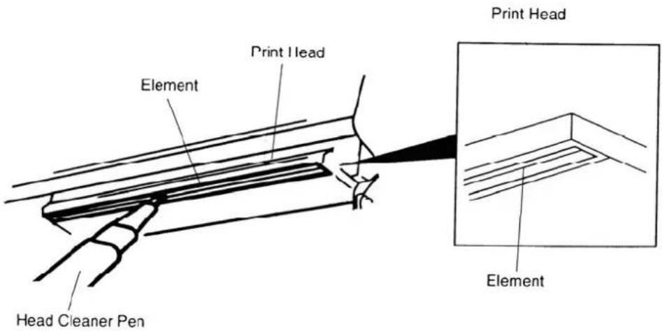
■ Cotton swab (Head cleaner pen)
■ Lint-free cloth
■ Vacuum / Blower brush
■ 100% ethanol
- The cleaning process is described as following
| Printer Part | Method Interval | |
| Print Head | 1. Always turn off the printer before cleaning the print head.2. Allow the print head to cool for a minimum of one minute.3. Use a cotton swab (Head cleaner pen) and 100% ethanol to clean the print head surface. | Clean the print head when changing a new label roll |
 | ||
| Platen Roller | 1. Turn the power off.2. Rotate the platen roller and wipe it thoroughly with 100% ethanol and a cotton swab, or lint-free cloth. | Clean the platen roller when changing a new label roll |
| Tear Bar/Peel Bar | Use the lint-free cloth with 100% ethanol to wipe it. | As needed |
| Sensor | Compressed air or vacuum Monthly | |
| Exterior | Wipe it with water-dampened cloth | As needed |
| Interior | Brush or vacuum As needed | |
Note:
- Do not touch printer head by hand. If you touch it careless, please use ethanol to clean it.
- Please use 100% Ethenol. DO NOT use medical alcohol, which may damage the printer head.
- Regularly clean the print head and supply sensors once change a new ribbon to keep printer performance and extend printer life.