BiPAC 7700N - Router Billion - Free user manual and instructions
Find the device manual for free BiPAC 7700N Billion in PDF.


User questions about BiPAC 7700N Billion
0 question about this device. Answer the ones you know or ask your own.
Ask a new question about this device
Download the instructions for your Router in PDF format for free! Find your manual BiPAC 7700N - Billion and take your electronic device back in hand. On this page are published all the documents necessary for the use of your device. BiPAC 7700N by Billion.
USER MANUAL BiPAC 7700N Billion
Chapter 1: Introduction....1
Introduction to your Router....1
Features 3
ADSL Compliance....3
Network Protocols and Features .... 3
Firewall....4
Quality of Service Control....4
ATM and PPP Protocols 4
IPTV Applications ^2 4
Wireless LAN 4
Management....5
Hardware Specifications....6
Physical Interface....6
Chapter 2: Installing the Router ....7
Package Contents 7
Important note for using this router....8
Device Description....9
The Front LEDs....9
The Rear Ports....10
Cabling 11
Chapter 3: Basic Installation 12
Connecting Your Router....13
Network Configuration....14
Configuring PC in windows 7....14
Configuring PC in Windows Vista 16
Configuring PC in Windows XP 18
Configuring PC in Windows 2000....19
Configuring PC in Windows 95/98/Me ....20
Configuring PC in Windows NT4.0 21
Factory Default Settings 22
Information from your ISP 24
Configuration via Web Interface 25
Quick Start....26
Chapter 4: Configuration....30
Device Info 31
Summary....32
WAN 33
Statistics....34
LAN 34
WAN Service....34
xTM....35
xDSL 36
Route 39
ARP 40
DHCP 41
Advanced setup....42
Layer2 Interface....43
ATM Interface 43
WAN Service 47
LAN - Local Area Network....67
NAT 70
Virtual Servers 70
Port Triggering 74
DMZ Host....77
Security....78
IP Filtering....78
Outgoing 78
Incomig 80
MAC Filtering 82
Parental Control....83
Time Restriction 83
Url Filter 85
QoS - Quality of Service 87
Queue Config....89
QoS Classification....92
Routing....100
Default Gateway 100
Static Route 101
Policy Routing 102
RIP 103
DNS 104
Dynamic DNS 105
DSL....106
UPnP 108
DNS Proxy 115
Interface Grouping....116
Multicast 119
Wireless....121
Basic 122
Security....124
MAC Filter 139
Wireless Bridge 141
Advanced 143
Station Info 146
Diagnostics....147
Management 148
Settings....149
Backup....149
Update 150
Restore Default Settings....151
System Log....152
SNMP Agent 154
TR-069 Client....155
Internet Time 157
Access Control 158
Passwords 158
Services 159
Update Software 160
Reboot....161
Tools 162
Chapter 5: Troubleshooting....163
Appendix: Product Support & Contact 165
Chapter 1: Introduction
Introduction to your Router
The BiPAC 7700N is an ADSL2+ Router that offers users affordable expanded wireless coverage and speedy Internet connection. With an integrated 802.11n Access Point, the BiPAC 7700N can automatically adopt an optimal connection to deliver smooth, constant signal reception even if obstacles are present. Robust Firewall security is featured to protect Internet access against hacker attacks. The Quality of Service and VLAN enables intelligent steaming for HD video or multiple applications such as music downloads, online gaming, video streaming and file sharing simultaneously.
Optimal Wireless Speeds and Coverage
With an integrated 802.11n Wireless Access Point, this router supports a data rates up to 300Mbps and delivers up to 6 times the speed and 3 times the wireless coverage of an 802.11b/g network device. If the network requires wider coverage, the built-in Wireless Distribution System (WDS) repeater function allows users to expand the wireless network without the need for any external wires or cables.
Jitter-free, Reliable Net Traffic
Quality of Service (QoS) gives full control over outgoing data traffic. Priority can be assigned by the router to ensure that important transmissions like gaming packets, VoIP calls or IPTV / streaming content passes through the router at lightning speed, even when there is heavy Internet traffic. The VLAN support is also capable of establishing reliable high-speed transmissions for wide bandwidth applications such as IPTV, VOD, or online gaming without consuming bandwidth.
High-speed Internet Access
The BiPAC 7700N is compliant with worldwide ADSL standards, and supports download rates of up to 12 / 24Mbps using ADSL2 / 2+, 8Mbps using ADSL and an upload rate of up to 1Mbps. The integrated Annex M standard supports ADSL2 / 2+ for higher uploads by doubling the upload data rate. The 4-port Ethernet Switch incorporated into the BiPAC 7700N enables users to connect to multiple computers or wired-Ethernet devices easily and enjoy blistering LAN transmission for multimedia applications such as interactive gaming, IPTV video streaming and real-time audio.
VLAN MUX
A Virtual LAN, commonly known as a VLAN, is a group of hosts with the common set of requirements that communicate as if they were attached to the same broadcast domain, regardless of the physical location. A VLAN has the same attributes as a physical LAN, but it allows for end stations to be grouped together even if they are not located on the same network switch.
The most commonly used Virtual LAN is defined by 802.1Q tagging protocol, which expended the original Ethernet frame header to include VLAN ID (tag) and priority bits. With the support of network equipments, multiple virtual networks can coexist over the same physical network. Ethernet frames are used to transfer data over ADSL line when bridging, MER or PPPoE mode is used.
While the DSL connection we usually configured is to use a PVC match a single service, PPPoE PPPoA, bridging, etc. With the VLAN tag, we can make virtual interfaces to create multiple separate WAN connections within the same PVC. It allows multiple services over the same PVC. The VLAN Mux feature is designed for this purpose. For example, you have an ATM interface, PVC with
VPI/VCI 8/35, you can set the PPPoE, IPoE, and Bridge connection via the PVC without respectively assigning the three services to three different PVCs.
Virtual AP
A “Virtual Access Point” is a logical entity that exists within a physical Access Point (AP). When a single physical AP supports multiple “Virtual APs”, each Virtual AP appears to stations (STAs) to be an independent physical AP, even though only a single physical AP is present. For example, multiple Virtual APs might exist within a single physical AP, each advertising a distinct SSID and capability set. Alternatively, multiple Virtual APs might advertise the same SSID but a different capability set – allowing access to be provided via Web Portal, WEP, and WPA simultaneously. Where APs are shared by multiple providers, Virtual APs provide each provider with separate authentication and accounting data for their users, as well as diagnostic information, without sharing sensitive management traffic or data between providers. You can enable the virtual AP.
Web Based GUI
It supports web based GUI for configuration and management. It is user-friendly and comes with online help. It also supports remote management capability for remote users to configure and manage this product.
Firmware Upgradeable
Device can be upgraded to the latest firmware through the WEB based GUI.
Features
• Supports Multiple LAN segment for multiple network application
• 4-port 10 / 100Mbps Ethernet switch integrated
- High-speed Internet Access via ADSL2 / 2+; Backward Compatible with ADSL
- 802.11n Wireless Access Point with Wi-Fi Protected Setup (WPS), Wi-Fi Protected Access (WPA-PSK/ WPA2-PSK) and Wired Equivalent Privacy (WEP) support
- Wireless speed up to 300Mbps
• Quality of Service Control for traffic prioritization management
• SOHO Firewall security with DoS Prevention and Packet Filtering
• Universal Plug and Play (UPnP) Compliance
• Dynamic Domain Name System (DDNS)
• Available Syslog
• Supports IPTV Application ^2
ADSL Compliance
- Compliant with ADSL Standard
- Full-rate ANSI T1.413 Issue 2
- G.dmt (ITU G.992.1)
- G.lite (ITU G.992.2)
- G.hs (ITU G.994.1)
- Compliant with ADSL2 Standard
- G.dmt.bis (ITU G.992.3)
- ADSL2 Annex M (ITU G.992.3 Annex M)
- Compliant with ADSL2+ Standard
- G.dmt.bis plus (ITU G.992.5)
- ADSL2+ Annex M (ITU G.992.5 Annex M)
Network Protocols and Features
• NAT, static routing and RIP-1 / 2
• Universal Plug and Play (UPnP) Compliant
• Dynamic Domain Name System (DDNS)
• Virtual Server and DMZ
• SNTP, DNS relay and IGMP proxy
• IGMP snooping for video service
- Management based-on IP protocol, port number and address
Firewall
• Built-in NAT Firewall
• Stateful Packet Inspection (SPI)
- Prevents DoS attacks including Land Attack, Ping of Death, etc.
- Remote access control for web base access
- Packet Filtering - port, source IP address, destination IP address, MAC address
- URL Filtering
- Password protection for system management
- VPN pass-through
Quality of Service Control
• Supports the DiffServ approach
- Traffic prioritization and bandwidth management based-on IP protocol, port number and address
ATM and PPP Protocols
• ATM Adaptation Layer Type 5 (AAL5)
• IP over Ethernet (RFC1483 / RFC2684)
• Classical IP over ATM (IPoA) (RFC 2225 / RFC 1577)
• VC and LLC based multiplexing
- PPP over Ethernet (PPPoE)
- PPP over ATM (RFC 2364)
• MAC Encapsulated Routing (RFC 1483 MER)
- OAM F4 / F5
IPTV Applications ^2
• Virtual LAN (VLAN)
• Quality of Service (QoS)
• IGMP Snooping & IGMP Proxy
- VLAN MUX support
Wireless LAN
- Compliant with IEEE 802.11n, 802.11g and 802.11b standards
• 2.4 GHz - 2.484 GHz frequency range - Up to 300Mbps wireless operation rate
- 64 / 128 bits WEP supported for encryption
- WPS (Wi-Fi Protected Setup) for easy setup
- Wireless Security with WPA-PSK / WPA2-PSK support
• WDS repeater function support
- 802.1x radius supported
- Web-based GUI and hardware push button for WLAN on/off switch control
Management
- Web-based GUI for remote and local management
- Firmware upgrades and configuration data upload and download via web-based GUI
- Embedded Telnet server for remote and local management
• Available Syslog
• Supports DHCP server / client / relay
• TR-069 ^3 supports remote management
• SNMP v1/v2 supports remote and local management

- The router may require firmware modification for certain ADSL2 / 2+ / Annex M DSLAMs.
- IPTV application may require subscribing to IPTV services from a Telco / ISP.
- Only upon request for Telco / ISP tender projects.
Hardware Specifications
Physical Interface
• WLAN: 2 x 2dbi antennas
- DSL: ADSL port
- Ethernet: 4-port 10 / 100Mbps auto-crossover (MDI / MDI-X) Switch
• Factory default reset button
- WPS push button
- WLAN On/Off push button
- Power jack
- Power switch
Chapter 2: Installing the Router
Package Contents
• BiPAC 7700N Wireless-N ADSL2+ Firewall Router
- CD containing the on-line manual and setup wizard utility
• RJ-11 ADSL/ telephone cable
- Ethernet (RJ-45) cable
- Power adapter
- Quick Start Guide
- Splitter / Micro-filter (Optional)
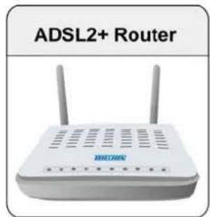
text_image
ADSL2+ Router
text_image
Quick Start Guide
natural_image
CD disc with visible internal structure and label 'CD' (no additional text or symbols)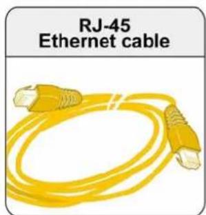
text_image
RJ-45 Ethernet cable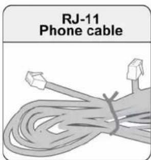
text_image
RJ-11 Phone cable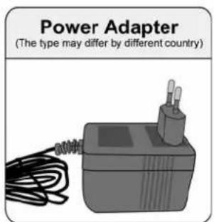
text_image
Power Adapter (The type may differ by different country)Important note for using this router

Warning
Do not use the router in high humidity or high temperatures.
Do not use the same power source for the router as other equipment.
Do not open or repair the case yourself. If the router is too hot, turn off the power immediately and have it repaired at a qualified service center.
Avoid using this product and all accessories outdoors.

Attention
Place the router on a stable surface.
Only use the power adapter that comes with the package. Using a different voltage rating power adaptor may damage the router.
Device Description
The Front LEDs
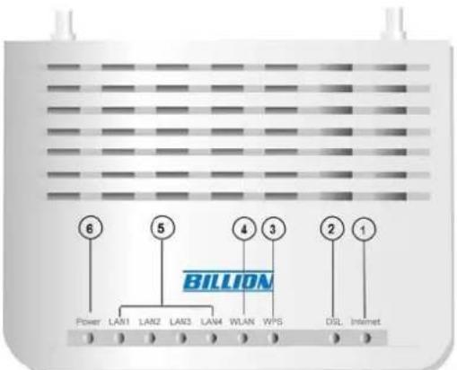
text_image
6 5 4 3 2 1 BILLION Power LAN1 LAN2 LAN3 LAN4 WLAN WPS DSL Internet| LED Meaning | ||
| 1 | Internet | Lit red when WAN port fails to get IP address.Lit green when WAN port gets IP address successfully.Unlit when the device is in bridge mode or WAN connection is absent. |
| 2 | DSL | Lit green when the device is successfully connected to an ADSL DSLAM. (“line sync”) |
| 3 | WPS | Flash green when WPS configuration is in progress. |
| 4 | WLAN | Lit green when a wireless connection is established.Unlit when wireless is disabled. |
| 5 | Ethernet port1X - 4X(RJ-45 connector) | Lit green when successfully connected to an Ethernet device.Blinking when data is being transmitted / received. |
| 6 | Power | When the system is ready, it will be lit green.Lit red when the device fails to boot. |
The Rear Ports
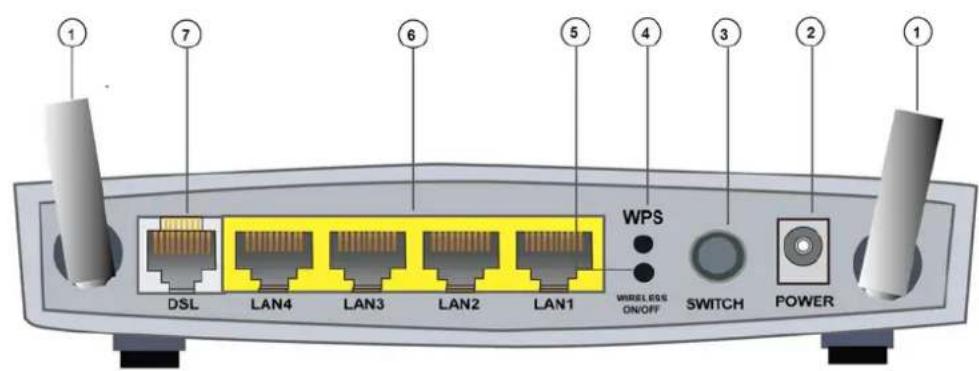
text_image
DSL LAN4 LAN3 LAN2 LAN1 WPS WIRELESS ON/OFF SWITCH POWER ① ⑦ ⑥ ⑤ ④ ③ ② ①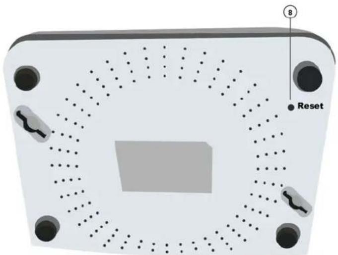
text_image
8 Reset| Port Meaning | ||
| 1 | Wireless Antenna | Wireless antennas. |
| 2 | Power | Connect it with the supplied power adapter. |
| 3 | Switch | Power ON/OFF switch. |
| 4 | WPS | Push WPS button to trigger Wi-Fi Protected Setup function.For WPS configuration detail, please refer toWPSSetupsection of this User Manual. |
| 5 | Wireless ON/OFF | Press to enable wireless when wireless is disabled and the WLAN LED lit.Press to disable wireless when wireless is on and the WLAN LED will be OFF. |
| 6 | Ethernet | Connect your computer to a LAN port using the included Ethernet cable (with RJ-45 cable) |
| 7 | DSL | Connect the supplied RJ-11 cable to this port when connecting to the ADSL/telephone network. |
| 8 | Reset(At the bottom of the device ) | Press for more than 5 seconds to restore the device to its factory default mode. |
Cabling
One of the most common causes of problems is bad cabling or ADSL line(s). Make sure that all connected devices are turned on. In the front panel of your router is a bank of LEDs. Verify that the LAN Link and ADSL line LEDs are lit. If they are not, verify if you are using the proper cables. If the error persists, you may have a hardware problem. In this case you should contact technical support.
Ensure that all other devices connected to the same telephone line as your router (e.g. telephones, fax machines, analogue modems) have a line filter connected between them and the wall socket (unless you are using a Central Splitter or Central Filter installed by a qualified and licensed electrician), and ensure that all line filters are correctly installed and the right way around. Missing line filters or line filters installed the wrong way around can cause problems with your ADSL connection, including causing frequent disconnections. If you have a back-to-base alarm system you should contact your security provider for a technician to make any necessary changes.
Chapter 3: Basic Installation
The router can be configured through your web browser. A web browser is included as a standard application in the following operating systems: Linux, Mac OS, Windows 7 / 98 / NT / 2000 / XP / Me / Vista, etc. The product provides an easy and user-friendly interface for configuration.
Please check your PC network components. The TCP/IP protocol stack and Ethernet network adapter must be installed. If not, please refer to your Windows-related or other operating system manuals.
There are ways to connect the router, either through an external repeater hub or connect directly to your PCs. However, make sure that your PCs have an Ethernet interface installed properly prior to connecting the router device. You ought to configure your PCs to obtain an IP address through a DHCP server or a fixed IP address that must be in the same subnet as the router. The default IP address of the router is 192.168.1.254 and the subnet mask is 255.255.255.0 (i.e. any attached PC must be in the same subnet, and have an IP address in the range of 192.168.1.1 to 192.168.1.253). The best and easiest way is to configure the PC to get an IP address automatically from the router using DHCP. If you encounter any problem accessing the router web interface it is advisable to uninstall your firewall program on your PCs, as they can cause problems accessing the IP address of the router. Users should make their own decisions on what is best to protect their network.
Please follow the following steps to configure your PC network environment.

Any TCP/IP capable workstation can be used to communicate with or through this router. To configure other types of workstations, please consult your manufacturer documentation.
Connecting Your Router
Users can connect the ADSL2+ router as follows.
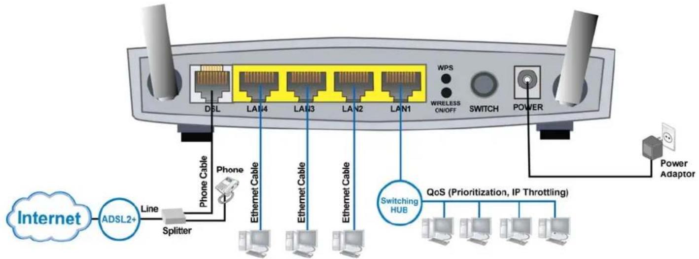
flowchart
graph TD
    A["Internet"] --> B["ADSL2+"]
    B --> C["Line"]
    C --> D["Splitter"]
    D --> E["Phone Cable"]
    E --> F["Ethernet Cable"]
    F --> G["Ethernet Cable"]
    G --> H["Ethernet Cable"]
    H --> I["Ethernet Cable"]
    I --> J["Ethernet Cable"]
    J --> K["Ethernet Cable"]
    K --> L["Switching HUB"]
    L --> M["QoS (Prioritization, IP Throttling)"]
    M --> N["Power Adaptor"]
    N --> O["POWER"]
    O --> P["WIRELESS ON/OFF"]
    P --> Q["Switch"]
    Q --> R["POWER"]
    R --> S["Switch"]
    S --> T["WPS"]
    T --> U["Switch"]
Network Configuration Configuring PC in windows 7
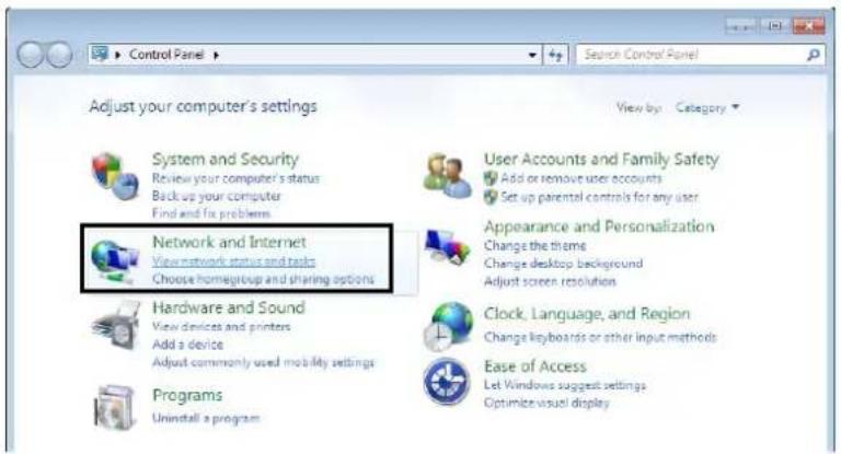
- Go to Start. Click on Control Panel. Then click on Network and Internet.
text_image
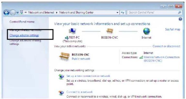
Control Panel Search Control Panel Adjust your computer's settings View by: Category System and Security Review your computer's status Back up your computer Find and fix problems Network and Internet View network status and tools Choose home/group and sharing options Hardware and Sound View devices and printers Add a device Adjust commonly used mobility settings Programs Uninstall a program User Accounts and Family Safety Add or remove user accounts Set up parental controls for any user Appearance and Personalization Change the theme Change desktop background Adjust screen resolution Clock, Language, and Region Change keyboards or other input methods Ease of Access Let Windows suggest settings Optimize visual display- When the Network and Sharing Center window pops up, select and click on Change adapter settings on the left window panel.
text_image
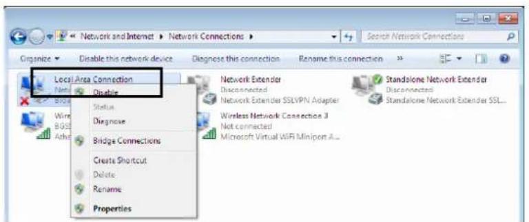
Control Panel Home Manage wireless networks Change adopter settings Change advanced sharing settings View your basic network information and set up connections TEST-PC (This computer) BGS10N-CNC Internet Set full map View your active networks Connect or disconnect BGS10N-CNC Public network Access type: Internet Connections: Wireless Network Connection (BGS10N-CNC) Change your networking settings Set up a new connection or network Set up a wireless, broadband, dial-up, ad hoc, or VPN connection; or set up a router or access point. Connect to a network Connect or reconnect to a wireless, wired, dial-up, or VPN network connection.- Select the Local Area Connection, and right click the icon to select Properties.
text_image
Network and Internet > Network Connections > Organize < Enable this network device Diagnose this connection Rename this connection Local Area Connection Nets Disable Status Diagnose Bridge Connections Create Shortcut Delete Rename Properties Network Extender Disconnected Network Extender SSLVPN Adapter Wireless Network Connection 3 Not connected Microsoft Virtual WiFi Miniport A... Standalone Network Extender Disconnected Standalone Network Extender SSL...-
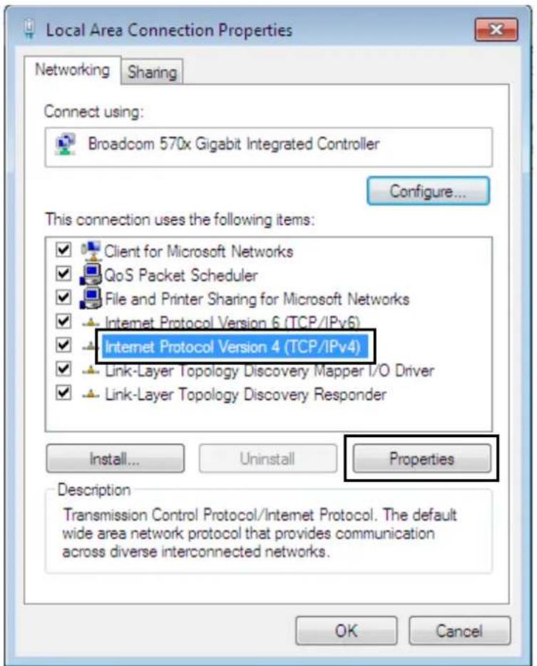
Select Internet Protocol Version 4 (TCP/IPv4) then click Properties.
-
In the TCP/IPv4 properties window, select the Obtain an IP address automatically and Obtain DNS Server address automatically radio buttons. Then click OK to exit the setting.
- Click OK again in the Local Area Connection Properties window to apply the new configuration.
text_image
Local Area Connection Properties Networking Sharing Connect using: Broadcom 570x Gigabit Integrated Controller Configure... This connection uses the following items: ✓ Client for Microsoft Networks ✓ QoS Packet Scheduler ✓ File and Printer Sharing for Microsoft Networks ✓ Internet Protocol Version 6 (TCP/IPv6) ✓ Internet Protocol Version 4 (TCP/IPv4) ✓ Link-Layer Topology Discovery Mapper I/O Driver ✓ Link-Layer Topology Discovery Responder Install... Uninstall Properties Description Transmission Control Protocol/Internet Protocol. The default wide area network protocol that provides communication across diverse interconnected networks. OK Cancel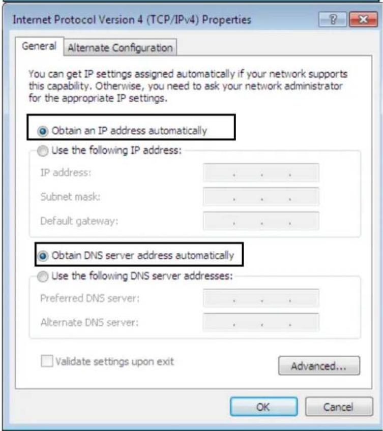
text_image
Internet Protocol Version 4 (TCP/IPv4) Properties General Alternate Configuration You can get IP settings assigned automatically if your network supports this capability. Otherwise, you need to ask your network administrator for the appropriate IP settings. Obtain an IP address automatically Use the following IP address: IP address: . Subnet mask: . Default gateway: . Obtain DNS server address automatically Use the following DNS server addresses: Preferred DNS server: . Alternate DNS server: . Validate settings upon exit Advanced... OK CancelConfiguring PC in Windows Vista
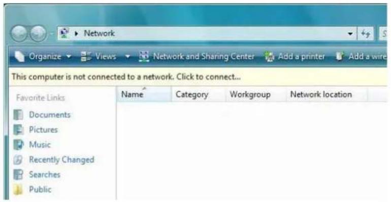
- Go to Start. Click on Network.
-
Then click on Network and Sharing Center at the top bar.
-
When the Network and Sharing Center window pops up, select and click on Manage network connections on the left window column.
-
Select the Local Area Connection, and right click the icon to select Properties..
text_image
Network Organize Views Network and Sharing Center Add a printer Add a wire This computer is not connected to a network. Click to connect... Favorite Links Name Category Workgroup Network location Documents Pictures Music Recently Changed Searches Public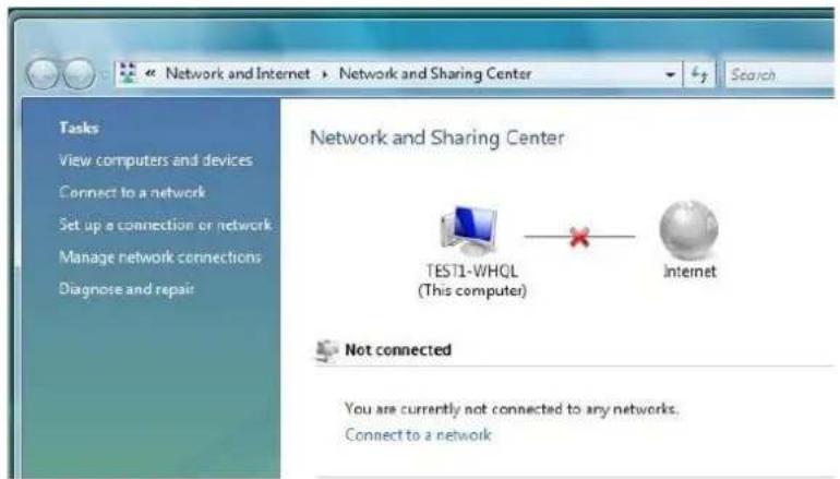
text_image
Network and Internet > Network and Sharing Center Search Tasks View computers and devices Connect to a network Set up a connection or network Manage network connections Diagnose and repair Network and Sharing Center TEST1-WHQL (This computer) Internet Not connected You are currently not connected to any networks. Connect to a network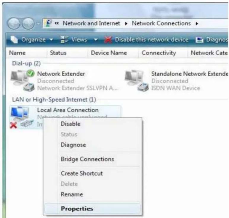
text_image
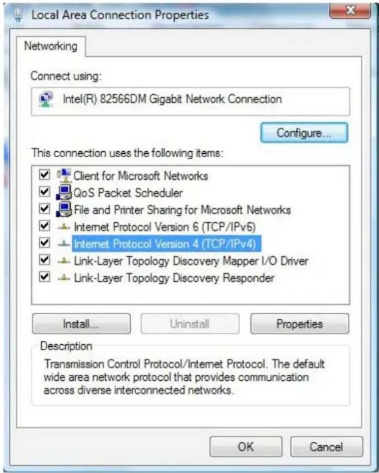
Network and Internet ▶ Network Connections ▶ Organize ▼ Views ▼ Disable this network device ▶ Diagnos Name Status Device Name Connectivity Network Cate Dial-up (2) Network Extender Disconnected Network Extender SSLVPN A... Standalone Network Extende Disconnected ISDN WAN Device LAN or High-Speed Internet (1) Local Area Connection Network cable unplanned Disable Status Diagnose Bridge Connections Create Shortcut Delete Rename Properties- Select Internet Protocol Version 4 (TCP/IPv4) then click Properties.
text_image
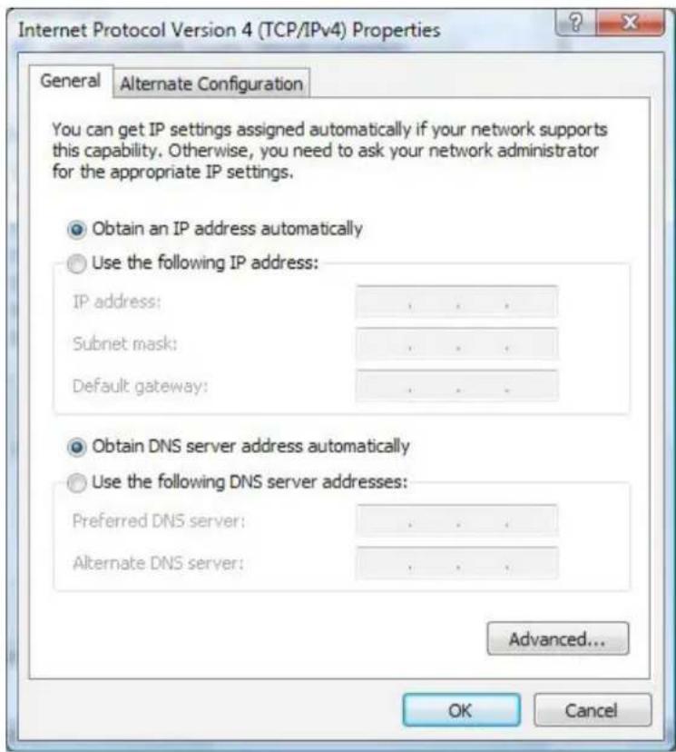
Local Area Connection Properties Networking Connect using: Intel(R) 82566DM Gigabit Network Connection Configure... This connection uses the following items: ✓ Client for Microsoft Networks ✓ QoS Packet Scheduler ✓ File and Printer Sharing for Microsoft Networks ✓ Internet Protocol Version 6 (TCP/IPv6) ✓ Internet Protocol Version 4 (TCP/IPv4) ✓ Link-Layer Topology Discovery Mapper I/O Driver ✓ Link-Layer Topology Discovery Responder Install... Uninstall Properties Description Transmission Control Protocol/Internet Protocol. The default wide area network protocol that provides communication across diverse interconnected networks. OK Cancel- In the TCP/IPv4 properties window, select the Obtain an IP address automatically and Obtain DNS Server address automatically radio buttons. Then click OK to exit the setting.
- Click OK again in the Local Area Connection Properties window to apply the new configuration.
text_image
Internet Protocol Version 4 (TCP/IPv4) Properties General Alternate Configuration You can get IP settings assigned automatically if your network supports this capability. Otherwise, you need to ask your network administrator for the appropriate IP settings. Obtain an IP address automatically Use the following IP address: IP address: . Subnet mask: . Default gateway: . Obtain DNS server address automatically Use the following DNS server addresses: Preferred DNS server: . Alternate DNS server: . Advanced... OK CancelConfiguring PC in Windows XP
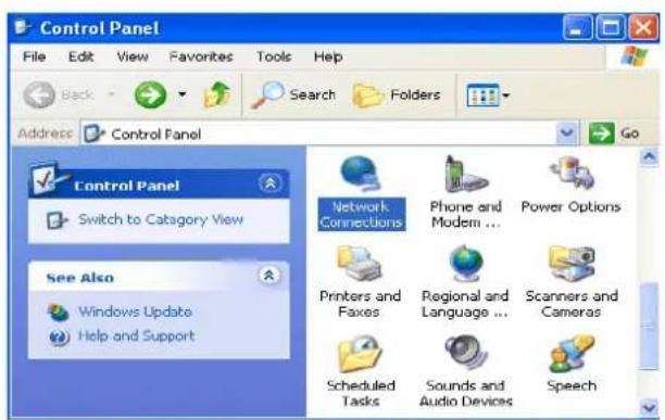
- Go to Start > Control Panel (in Classic View). In the Control Panel, double-click on Network Connections
-
Double-click Local Area Connection.
-
In the Local Area Connection Status window, click Properties.
-
Select Internet Protocol (TCP/IP) and click Properties.
-
Select the Obtain an IP address automatically and the Obtain DNS server address automatically radio buttons.
- Click OK to finish the configuration.
text_image
Control Panel File Edit View Favorites Tools Help Back Search Folders Address Control Panel Control Panel Switch to Category View See Also Windows Update Help and Support Network Connections Phone and Modem ... Power Options Printers and Faxes Regional and Language ... Scanners and Cameras Scheduled Tasks Sounds and Audio Devices Speech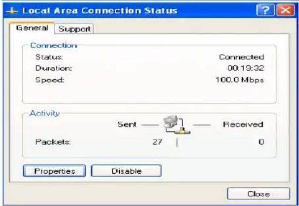
text_image
Local Area Connection Status General Support Connection Status: Connected Duration: 00:19:32 Speed: 100.0 Mbps Activity Sent — Received Packets: 27 0 Properties Disable Close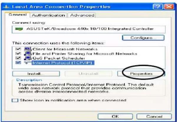
text_image
Local Area Connection Properties General Authentication Advanced Connect using: ASUSTeK/Broadcom 440x 10/100 Integrated Controller Configure... This connection uses the following items: ✓ Client for Microsoft Networks ✓ File and Printer Sharing for Microsoft Networks ✓ DoS Packet Scheduler ✓ Internet Protocol [TCP/IP] Install... Uninstall Properties Description Transmission Control Protocol/Internet Protocol. The default wide area network protocol that provides communication across diverse interconnected networks. Show icon in notification area when connected OK Cancel
text_image
Internet Protocol (TCP/IP) Properties General Alternate Configuration You can get IP settings assigned automatically if your network supports this capability. Otherwise, you need to ask your network administrator for the appropriate IP settings. Obtain an IP address automatically Use the following IP address: IP address: Subnet mask: Default gateway: Obtain DNS server address automatically Use the following DNS server addresses: Preferred DNS server: Alternate DNS server: Advanced... OK CancelConfiguring PC in Windows 2000
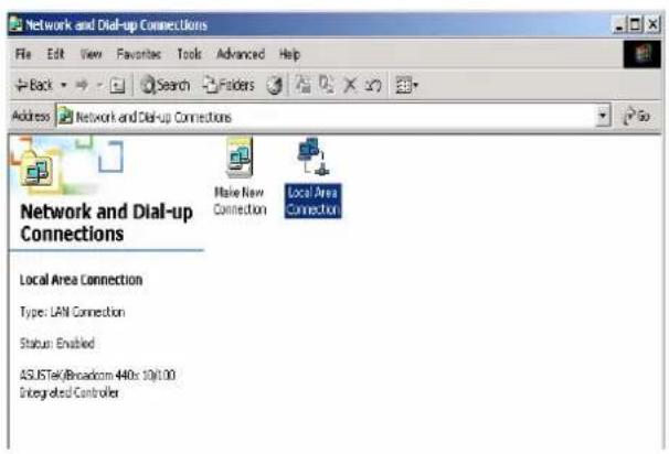
- Go to Start > Settings > Control Panel. In the Control Panel, double-click on Network and Dial-up Connections.
- Double-click Local Area Connection.
- In the Local Area Connection Status window click Properties.
- Select Internet Protocol (TCP/IP) and click Properties.
- Select the Obtain an IP address automatically and the Obtain DNS server address automatically radio buttons.
- Click OK to finish the configuration.
text_image
Network and Dial-up Connections File Edit View Favorites Tools Advanced Help Back Search Folders Address Network and Dial-up Connections Make New Connection Local Area Connection Network and Dial-up Connections Local Area Connection Type: LAN Connection Status: Enabled ASUSTek/Broadcom 440s 10x1.00 Integrated Controller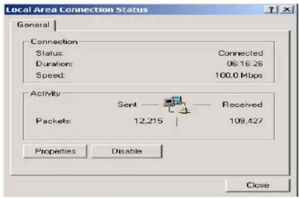
text_image
Local Area Connection Status General Connection Status: Connected Duration: 06:18:26 Speed: 100.0 Mbps Activity Sent Received Packets: 12,215 | 109,427 Properties Disable Close
text_image
Local Area Connection Properties General Connect using: ASUSTeK/Broadcom 440x 10/100 Integrated Controller Configure Components checked are used by this connection: Client for Microsoft Networks File and Printer Sharing for Microsoft Networks Internet Protocol (TCP/IP) Install... Uninstall Properties Description Transmission Control Protocol/Internet Protocol. The default wide area network protocol that provides communication across diverse interconnected networks. Show icon in taskbar when connected OK Cancel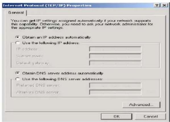
text_image
Internet Protocol (TLP/IP) Properties General You can get IP settings assigned automatically if your network supports this capability. Otherwise, you need to ask your network administrator for the appropriate IP settings. Obtain an IP address automatically Use the following IP address: IP address: Submit music: Default gateway: Obtain DNS server address automatically Use the following DNS server addresses: Preferred DNS server: Alternate DNS server: Advanced... OK CancelConfiguring PC in Windows 95/98/Me
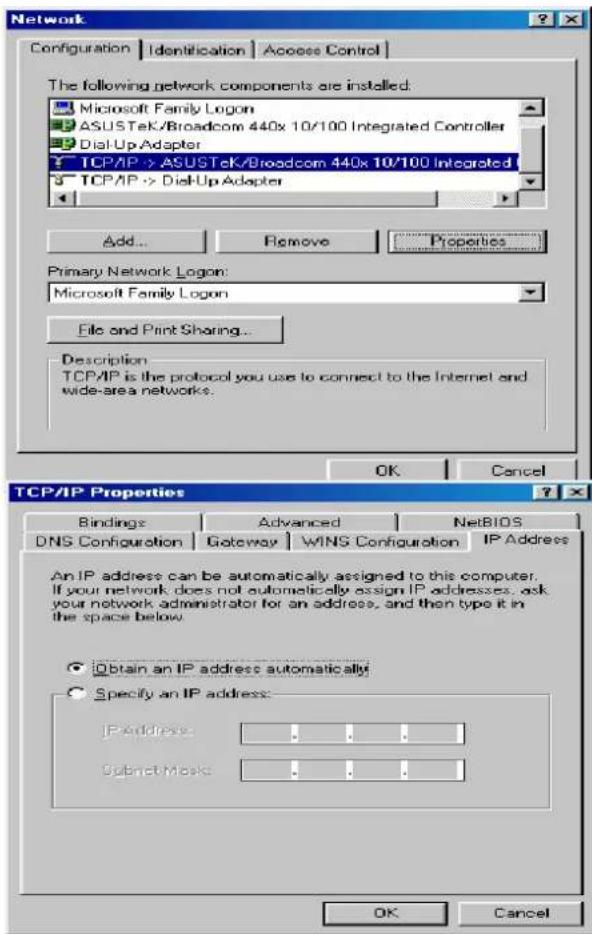
- Go to Start > Settings > Control Panel. In the Control Panel, double-click on Network and choose the Configuration tab.
-
Select TCP/IP > NE2000 Compatible, or the name of your Network Interface Card (NIC) in your PC.
-
Select the Obtain an IP address automatically radio button.
-
Then select the DNS Configuration tab.
- Select the Disable DNS radio button and click OK to finish the configuration.
text_image
Network Configuration | Identification | Access Control | The following network components are installed: Microsoft Family Logon ASUSTeK/Broadcom 440x 10/100 Integrated Controller Dial-Up Adapter TCP/IP -> ASUSTeK/Broadcom 440x 10/100 Integrated TCP/IP -> Dial-Up Adapter Add... Remove Properties Primary Network Logon: Microsoft Family Logon File and Print Sharing... Description TCP/IP is the protocol you use to connect to the Internet and wide-area networks. OK Cancel TCP/IP Properties Bindings Advanced NetBIOS DNS Configuration Gateway WINS Configuration IP Address An IP address can be automatically assigned to this computer. If your network does not automatically assign IP addresses, ask your network administrator for an address, and then type it in the space below. Obtain an IP address automatically! Specify an IP address: IP Address Subnet Mask OK Cancel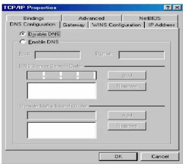
text_image
TCP/IP Properties Bindings Advanced NetsBIOS DNS Configuration Gateway WINS Configuration IP Address Disable DNS Enable DNS Host Domains: DNS Server Search Order Add Remove Domain Suffix Search Order Add Remove OK CancelConfiguring PC in Windows NT4.0
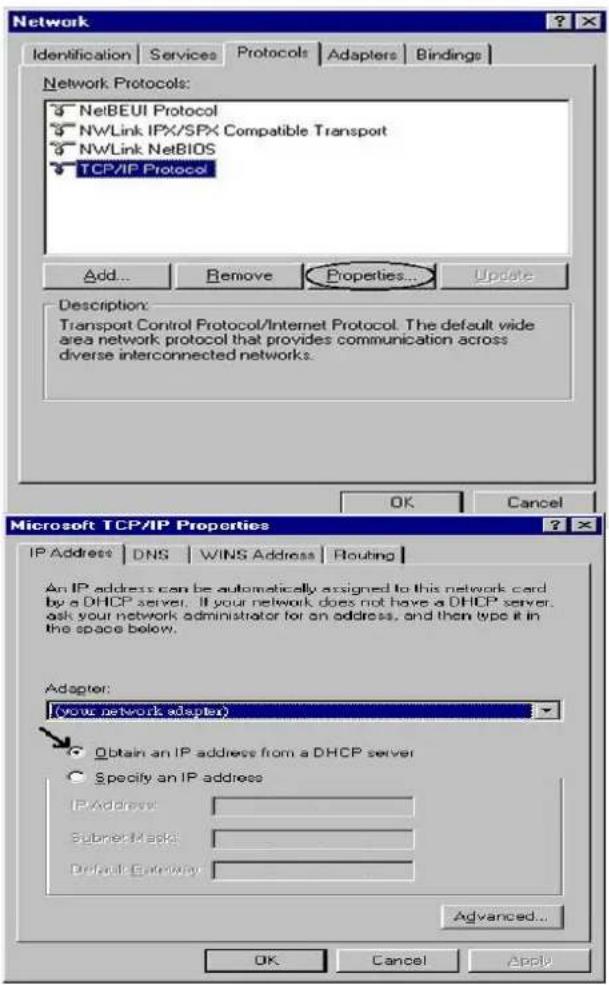
- Go to Start > Settings > Control Panel. In the Control Panel, double-click on Network and choose the Protocols tab.
-
Select TCP/IP Protocol and click Properties.
-
Select the Obtain an IP address from a DHCP server radio button and click OK.
text_image
Network Identification Services Protocols Adapters Bindings Network Protocols: 3 NetBEUI Protocol 3 NWLink IPX/SPX Compatible Transport 3 NWLink NetBIOS TCP/IP Protocol Add... Remove Properties... Update Description: Transport Control Protocol/Internet Protocol. The default wide area network protocol that provides communication across diverse interconnected networks. OK Cancel Microsoft TCP/IP Properties IP Address DNS WINS Address Routing An IP address can be automatically assigned to this network card by a DHCP server. If your network does not have a DHCP server, ask your network administrator for an address, and then type it in the space below. Adapter: (your network adapter) Obtain an IP address from a DHCP server Specify an IP address IPAddress Subnet mask Default Gateway Advanced... OK Cancel ApplyFactory Default Settings
Before configuring your router, you need to know the following default settings.
Web Interface (Username and Password)
Three user accounts are provided by this router, admin, support and user respectively. See Access Control.
Admin: the one who has unrestricted access to change and view configuration of your Broadband Router.
Username: admin
Password: admin
- Support (Remote): is used to allow an ISP technician to access your Broadband Router for maintenance and to run diagnostics.
Username: support
▶ Password: support
- User (local): the local user who can access the Broadband Router, view configuration settings and statistics, as well as, update the router's software.
Username: user
Password: user

Attention
If you have forgotten the username or password of the router, you can restore the device to its default setting by pressing the Reset button for more than 5 seconds.
Device LAN IPv4 settings
IPv4 Address: 192.168.1.254
Subnet Mask: 255.255.255.0
DHCP server for IPv4
DHCP server is enabled.
Start IP Address: 192.168.1.1
IP pool counts: 20
LAN and WAN Port Addresses
The parameters of LAN and WAN ports are pre-set in the factory. The default values are shown in the table.
IPv4
| LAN Port | WAN Port | |
| IPv4 address 192.168.1.254 | The PPPoE function is enabled to automatically get the WAN port configuration from the ISP. | |
| Subnet Mask 255.255.255.0 | ||
| DHCP server function Enabled | ||
| IP addresses for distribution to PCs | 20 IP addresses continuing from 192.168.1.1 through 192.168.1.20 | |
Information from your ISP
Before configuring this device, you have to check with your ISP (Internet Service Provider) to find out what kind of service is provided such as DHCP (Obtain an IP Address Automatically, Static IP (Fixed IP Address) or PPPoE.
Gather the information as illustrated in the following table and keep it for reference.
| PPPoE(RFC2516) | VPI/VCI, VC / LLC-based multiplexing, Username, Password, Service Name, and Domain Name System (DNS) IP address (it can be automatically assigned by your ISP when you connect or be set manually). |
| PPPoA(RFC2364) | VPI/VCI, VC / LLC-based multiplexing, Username, Password and Domain Name System (DNS) IP address (it can be automatically assigned by your ISP when you connect or be set manually). |
| IPoA(RFC1577) | VPI/VCI, VC / LLC-based multiplexing, IP address, Subnet mask, Gateway address, and Domain Name System (DNS) IP address (it is a fixed IP address). |
| IP over Ethernet (RFC1483/RFC2684) | VPI/VCI, VC / LLC-based multiplexing, IP address, Subnet mask, Gateway address, and Domain Name System (DNS) IP address (it can be automatically assigned by your ISP when you connect or set manually). |
| Pure Bridge | VPI/VCI, VC / LLC-based multiplexing to use Bridged Mode. |
Configuration via Web Interface
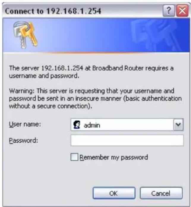
Open your web browser; enter the IP address of your router, which by default is 192.168.1.254, and click → or press 'Enter' key on the keyboard, a login prompt window will appear. The default root username and password are "admin" and "admin" respectively.
text_image
Connect to 192.168.1.254 The server 192.168.1.254 at Broadband Router requires a username and password. Warning: This server is requesting that your username and password be sent in an insecure manner (basic authentication without a secure connection). User name: admin Password: Remember my password OK CancelCongratulations! You are now successfully logged in to the Firewall Router!
After logging in to the router you will see Quick Start Wizard as shown below, please follow the steps on following pages to configure your device.

text_image
WAN Interface (WAN > Wireless) WAN Interface Main Port DSL Continue Jump to Wireless setting Skip Quick SetupQuick Start
This part is to let you quickly configure and start your router to access internet.

text_image
WAN Interface (WAN > Wireless) WAN Interface Main Port DSL Continue Jump to Wireless setting Skip Quick Setup- Select DSL, press Continue to go on to next step, or if you only want to configure Wireless, press Jump to Wireless setting to go to step 8. Click Quick Setup to give up and return to the Device Info page.
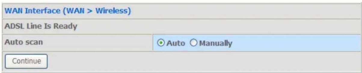
- When ADSL line is not ready, the screen1 below will appear to remind you. Then you should connect the ADSL line. While ADSL line is ready, the screen 2 below will appear to let you go on. Here you can select Auto or Manually. Select Auto will go to step 3, and select manually will go to step 4.

text_image
WAN Interface (WAN > Wireless) DSL line is not ready, Please check your DSL line and wait for a while. BackScreen 1
text_image
WAN Interface (WAN > Wireless) ADSL Line Is Ready Auto scan Auto Manually ContinueScreen 2
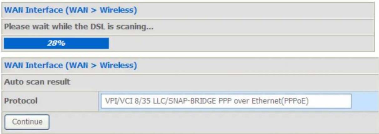
- Here wait while the DSL is scanning, when the scanning is OK, the scanning result will appear, see screen 3, and then it will quickly go to step 6. If the scanning fails, you will also be lead to step 4.
text_image
WAN Interface (WAN > Wireless) Please wait while the DSL is scanning... 28% WAN Interface (WAN > Wireless) Auto scan result Protocol VPI/VCI 8/35 LLC/SNAP-BRIDGE PPP over Ethernet(PPPoE) ContinueScreen 3
- Here you should select the Layer2 Interface, ATM. Click Add to add WAN Interface.
| WAN Interface | ||||||||||
| Select Layer2 Interface | ||||||||||
| Layer2 Interface ATM✓ | ||||||||||
| Interface | VPI | VCI | Category | Link Type | Connection Mode | IP QOS | Scheduler Alg | Queue Weight | Group Precedence | Apply |
| Add | ||||||||||
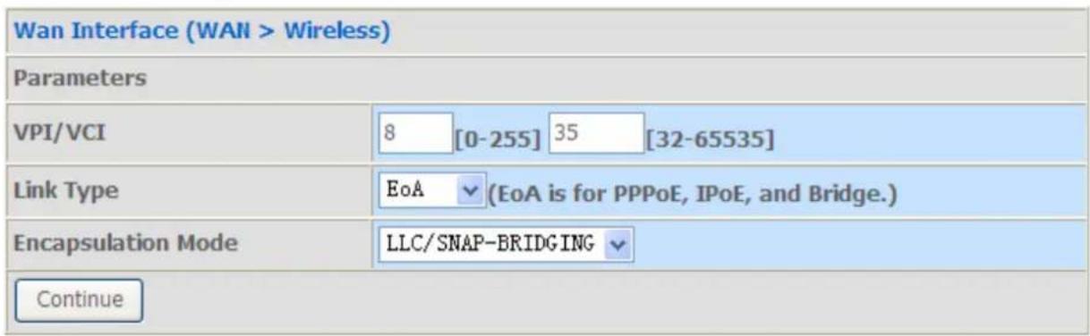
- According to your ISP, type the VPI/VCI, select appropriate Link type and the Encapsulation mode. Click Continue to go to next step.
text_image
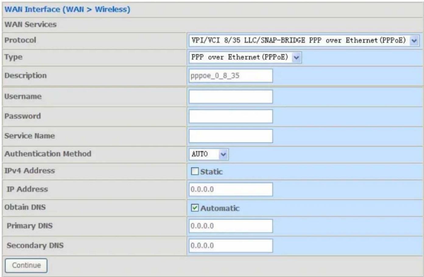
Wan Interface (WAN > Wireless) Parameters VPI/VCI 8 [0-255] 35 [32-65535] Link Type EoA (EoA is for PPPoE, IPoE, and Bridge.) Encapsulation Mode LLC/SNAP-BRIDGING Continue- Enter the username, password from your ISP, for IP and DNS settings, also refer to your ISP. Click Continue to go on.
text_image
WAN Interface (WAN > Wireless) WAN Services Protocol VPI/VCI 8/35 LLC/SNAP-BRIDGE PPP over Ethernet (PPPoE) Type PPP over Ethernet (PPPoE) Description pppoe_0_8_35 Username Password Service Name Authentication Method AUTO IPv4 Address Static IP Address 0.0.0.0 Obtain DNS Automatic Primary DNS 0.0.0.0 Secondary DNS 0.0.0.0 Continue- WAN port configuration has been finished.

text_image
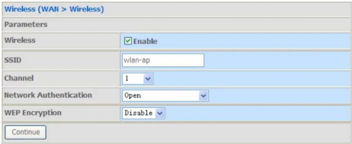
WAN Interface (WAN > Wireless) Congratulations! Your WAN port has been successfully configured. Next to Wireless- After the configuration is successful, click Next to Wireless button and you may proceed to configure the Wireless setting. For security information, please turn to wireless>security section in this manual for help. Click Continue.
text_image
Wireless (WAN > Wireless) Parameters Wireless Enable SSID wlan-ap Channel 1 Network Authentication Open WEP Encryption Disable Continue- Configuration's successful.
| Process Finished |
| Success. |
You've now configured your router and can now access the internet, turn to Device Info, you will see basic information".
| Device Info Summary WAN Statistics Route ARP DHCP Quick Start Advanced Setup Wireless Diagnostics Management | Device Info | |
| Model Name: | BiPAC 7700N | |
| Software Version: | B038_K82_GH-00-1659 | |
| Bootloader (CFE) Version: | 1.0.37-106.5 | |
| DSL PHY and Driver Version: | A2pD030g.d22j | |
| Wireless Driver Version: | 5.60.120.3.cpe4.406.0 | |
| This information reflects the current status of your WAN connection. | ||
| Line Rate - Upstream (Kbps): | 1083 | |
| Line Rate - Downstream (Kbps): | 23541 | |
| LAN IPv4 Address: | 192.168.1.254 | |
| MAC Address: | 00:04:ed:77:00:01 | |
| Default Gateway: | ppp0 | |
| Primary DNS Server: | 168.95.192.1 | |
| Secondary DNS Server: | 168.95.1.1 | |
| Date/Time: | Mon Jan 17 10:20:23 | |
For more information, turn to Advanced setup for help.
Chapter 4: Configuration
Once you have logged on to your BiPAC 7700N Router via your web browser, you can begin to set it up according to your requirements. On the configuration homepage, the left navigation pane links you directly to the setup pages, which include:
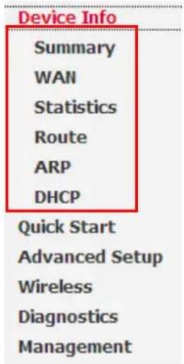
Device Info (Summary, WAN, Statistics, Route, ARP, DHCP)
Quick Start
Advanced Setup (Layer2 Interface, WAN Service, LAN, NAT, Security, Parental Control, URL Filtering, Quality of Service, Routing, DNS, DSL, UPnP, DNS Proxy, Interface Grouping, Multicast)
Wireless (Basic, Security, MAC Filter, Wireless Bridge, Advanced, Station Info)
Diagnostic
Management (Settings, System Log, SNMP Agent, TR-069 Client, Internet Time, Access Control, Update Software, Reboot, Tools)
Device Info
This Section gives users an easy access to the information about the working router and view the current status of the router. Here Summary, WAN, Statistics, Router, ARP and DHCP six subsections are included.
text_image
Device Info Summary WAN Statistics Route ARP DHCP Quick Start Advanced Setup Wireless Diagnostics ManagementSummary
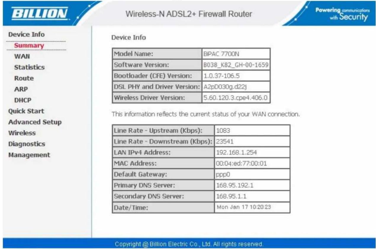
The basic information about the device is provided here (the following is a configured screenshots to let users understand clearly).
text_image
Device Info Summary WAN Statistics Route ARP DHCP Quick Start Advanced Setup Wireless Diagnostics Management Wireless Driver Version: BiPAC 7700N Software Version: B038_K82_GH-00-1659 Bootloader (CFE) Version: 1.0.37-106.5 DSL PHY and Driver Version: A2pD030g.d22j Wireless Driver Version: 5.60.120.3.cpe4.406.0 This information reflects the current status of your WAN connection. Line Rate - Upstream (Kbps): 1083 Line Rate - Downstream (Kbps): 23541 LAN IPv4 Address: 192.168.1.254 MAC Address: 00:04:ed:77:00:01 Default Gateway: ppp0 Primary DNS Server: 168.95.192.1 Secondary DNS Server: 168.95.1.1 Date/Time: Mon Jan 17 10:20:23 Copyright @ Billion Electric Co., Ltd. All rights reserved.Device Information
Model Name: Display the model name.
Software Version: Firmware version.
DSL PHY and Driver Version: Display DSL PHY and Driver version.
Wireless Driver Version: Display wireless driver version.
WAN
Line Rate – Upstream (Kbps): Display Upstream line Rate in Kbps.
Line Rate – Downstream (Kbps): Display Downstream line Rate in Kbps.
LAN IPv4 Address: Display the LAN IPv4 address.
MAC Address: Display the MAC address.
Default Gateway: Display Default Gateway.
Primary DNS Server: Display IPV4 address of Primary DNS Server.
Secondary DNS Server: Display IPV4 address of Secondary DNS Server.
Date/Time: Display the current exact date and time, needed to synchronize with Internet time server to obtain the right time, see Internet Time.
WAN
This table displays the information of the WAN connections, users can turn here for WAN connection information.
WAN Info
| Interface | Description | Type | VlanMuxId | Igmp | NAT | Firewall | Status | IPv4 Address |
| ppp0 | pppoe_0_8_35 | PPPoE | Disabled | Disabled | Enabled | Enabled | Connected | 111.251.230.225 |
Interface: the WAN connection interface.
Description: the description of this connection.
Type: the protocol used by this connection.
VlanMuxId: Show the status of the VLANMuxId, VLAN ID or disabled. If VLAN ID is -1, then disabled is shown in this field, while if VLAN ID isn't -1, the exact VLAN ID is shown here in this field.
Igmp: Display the status of IGMP, disabled or enabled.
NAT: Display the status of NAT, disabled or enabled.
Firewall: Display the status of Firewall, disabled or enabled.
Status: Display the status of this WAN connection.
IPv4 Address: the WAN IPv4 Address the device obtained.
Statistics
LAN
The table shows the statistics of LAN.
Statistics -- LAN
| Interface | Received | Transmitted | ||||||
| Bytes | Pkts | Errs | Drops | Bytes | Pkts | Errs | Drops | |
| LAN1 | 224120 | 1848 | 0 | 0 | 833880 | 1549 | 0 | 0 |
| LAN2 | 0 | 0 | 0 | 0 | 0 | 0 | 0 | 0 |
| LAN3 | 0 | 0 | 0 | 0 | 0 | 0 | 0 | 0 |
| LAN4 | 0 | 0 | 0 | 0 | 0 | 0 | 0 | 0 |
| wI0 | 0 | 0 | 0 | 0 | 36605 | 162 | 10 | 0 |
Reset Statistics
Interface: List each LAN interface. LAN1-LAN4 indicate the four LAN interfaces.
Bytes: Display the Received and Transmitted traffic statistics in Bytes.
Pkts: Display the Received and Transmitted traffic statistics in Packets.
Errs: Display the statistics of errors arising in Receiving or Transmitting data.
Drops: Display the statistics of drops arising in Receiving or Transmitting data.
Reset Statistics: Press this button to get the latest information.
WAN Service
The table shows the statistics of WAN.
Statistics -- WAN
| Interface | Description | Received | Transmitted | ||||||
| Bytes | Pkts | Errs | Drops | Bytes | Pkts | Errs | Drops | ||
| ppp0 | pppoe_0_8_35 | 105757 | 276 | 0 | 0 | 9249 | 279 | 0 | 0 |
Reset Statistics
Interface: Display the connection interface.
Description: the description for the connection.
Bytes: Display the WAN Received and Transmitted traffic statistics in Bytes.
Pkts: Display the WAN Received and Transmitted traffic statistics in Packests.
Errs: Display the statistics of errors arising in Receiving or Transmitting data.
Drops: Display the statistics of drops arising in Receiving or Transmitting data.
Reset Statistics: Press this button to get the latest information.
xTM
The Statistics-xTM screen displays all the xTM statistics
Interface Statistics
| Port Number | In Octets | Out Octets | In Packets | Out Packets | In OAM Cells | Out OAM Cells | In ASM Cells | Out ASM Cells | In Packet Errors | In Cell Errors |
| 1 | 1259700 | 321233 | 1753 | 1170 | 0 | 0 | 0 | 0 | 0 | 268 |
Reset
Port Number: Shows number of the port for xTM.
In Octets: Number of received octets over the interface.
Out Octets: Number of transmitted octets over the interface.
In Packets: Number of received packets over the interface.
Out Packets: Number of transmitted packets over the interface.
In OAM Cells: Number of OAM cells received.
Out OAM Cells: Number of OAM cells transmitted.
In ASM Cells: Number of ASM cells received.
Out ASM Cells: Number of ASM cells transmitted.
In Packet Errors: Number of received packets with errors.
In Cell Errors: Number of received cells with errors.
Reset: Click to reset the statistics.
Statistics -- xDSL
| Mode: | ADSL_2plus | |
| Traffic Type: | ATM | |
| Status: | Up | |
| Link Power State: | L0 | |
| Downstream | Upstream | |
| Line Coding(Trellis): | On | On |
| SNR Margin (0.1 dB): | 51 | 60 |
| Attenuation (0.1 dB): | 20 | 30 |
| Output Power (0.1 dBm): | 0 | 46 |
| Attainable Rate (Kbps): | 22168 | 1148 |
| Path 0 | Path 1 | |||
| Downstream | Upstream | Downstream | Upstream | |
| Rate (Kbps): | 22738 | 1115 | 0 | 0 |
| MSGc (# of bytes in overhead channel message): | 54 | 66 | 0 | 0 |
| B (# of bytes in Mux Data Frame): | 254 | 34 | 0 | 0 |
| M (# of Mux Data Frames in FEC Data Frame): | 1 | 1 | 0 | 0 |
| T (Mux Data Frames over sync bytes): | 3 | 1 | 0 | 0 |
| R (# of check bytes in FEC Data Frame): | 0 | 0 | 0 | 0 |
| S (ratio of FEC over PMD Data Frame length): | 0.3583 | 0.9756 | 0.0 | 0.0 |
| L (# of bits in PMD Data Frame): | 5692 | 287 | 0 | 0 |
| D (interleaver depth): | 1 | 1 | 0 | 0 |
| Delay (msec): | 0.8 | 0.24 | 0.0 | 0.0 |
| INP (DMT symbol): | 0.0 | 0.0 | 0.0 | 0.0 |
| Super Frames: | 0 | 0 | 0 | 0 |
| Super Frame Errors: | 6 | 0 | 0 | 0 |
| RS Words: | 0 | 0 | 0 | 0 |
| RS Correctable Errors: | 0 | 0 | 0 | 0 |
| RS Uncorrectable Errors: | 0 | 0 | 0 | 0 |
| HEC Errors: | 48 | 0 | 0 | 0 |
| OCD Errors: | 0 | 0 | 0 | 0 |
| LCD Errors: | 0 | 0 | 0 | 0 |
| Total Cells: | 31466365 | 1500799 | 0 | 0 |
| Data Cells: | 11842 | 1066 | 0 | 0 |
| Bit Errors: | 0 | 0 | 0 | 0 |
| Total ES: | 1 | 0 |
| Total SES: | 0 | 0 |
| Total UAS: | 16 | 16 |
xDSL BER Test Reset Statistics
Mode: Modulation protocol, including G.dmt, G.lite, T1.413, ADSL2, AnnexL, ADSL2+ and AnnexM.
Traffic Type: transfer mode, ATM.
Status: Show the status of DSL link.
Link Power State: Show link output power state.
Line Coding (Trellis): Trellis on/off.
SNR Margin (0.1 dB): show the Signal to Noise Ratio(SNR) margin.
Attenuation (0.1 dB): This is estimate of average loop attenuation of signal.
Output Power (0.1 dBm): show the output power.
Attainable Rate (Kbps) : The sync rate you would obtain.
Rate (Kbps): show the downstream and upstream rate in Kbps.
Super Frames: the total number of super frames.
Super Frame Errors: the total number of super frame errors.
RS Words: Total number of Reed-Solomon code errors.
RS Correctable Errors: Total number of RS with correctable errors.
RS Uncorrectable Errors: Total number of RS words with uncorrectable errors.
HEC Errors: Total number of Header Error Checksum errors.
OCD Errors: Total number of out-of-cell Delineation errors.
LCD Errors: Total number of Loss of Cell Delineation.
Total Cells: Total number of cells.
Data Cells: Total number of data cells.
Bit Errors: Total number of bit errors.
Total ES: Total Number of Errored Seconds.
Total SES: Total Number of Severely Errored Seconds.
Total UAS: Total Number of Unavailable Seconds.
xDSL BER Test: Click this button to start a bit Error Rate Test. The ADSL Bit Error Rate (BER) test determines the quality of the ADSL connection. The test is done by transferring idle cells containing a known pattern and comparing the received data with this known pattern to check for any errors.
ADSL BER Test - Start
The ADSL Bit Error Rate (BER) test determines the quality of the ADSL connection. The test is done by transferring idle cells containing a known pattern and comparing the received data with this known pattern to check for any errors.
Select the test duration below and click "Start".
Tested Time (sec): 20
Start Close
Select the Tested Time(sec), press Start to start test.
ADSL BER Test - Running
The xDSL BER test is in progress. The connection speed is 24108 Kbps. The test will run for 20 seconds.
Click "Stop" to terminate the test.
Stop Close
When it is OK, the following test result window will appear. You can view the quality of ADSL connection. Here the connection is OK.
ADSL BER Test - Result
The ADSL BER test completed successfully.
| Test Time (sec): | 20 |
| Total Transferred Bits: | 0x000000001A071B00 |
| Total Error Bits: | 0x0000000000000000 |
| Error Ratio: | 0.00e+00 |
Close
Reset : Click this button to reset the statistics.
Route
Device Info -- Route
Flags: U - up, ! - reject, G - gateway, H - host, R - reinstate D - dynamic (redirect), M - modified (redirect).
| Destination | Gateway | Subnet Mask | Flag | Metric | Service | Interface |
| 112.80.156.1 | 0.0.0.0 | 255.255.255.255 | UH | 0 | pppoe_0_8_35 | ppp0 |
| 192.168.1.0 | 0.0.0.0 | 255.255.255.0 | U | 0 | br0 | |
| 0.0.0.0 | 0.0.0.0 | 0.0.0.0 | U | 0 | pppoe_0_8_35 | ppp0 |
Destination: the IP address of destination network.
Gateway: the IP address of the gateway this route uses.
Subnet Mask: the destination subnet mask.
Flag: show the status of the route.
① U: show the route is activated or enabled.
① H (host): destination is host not the subnet.
① G: show that the outside gateway is needed to forward packets in this route.
① R: show that the route is reinstated from dynamic routing.
① D: show that the route is dynamically installed by daemon or redirecting.
① M: show the route is modified from routing daemon or redirect.
Metric: Display the number of hops counted as the Metric of the route.
Service: Display the service that this route uses.
Interface: Display the existing interface this route uses.
ARP
This section displays the router's ARP (Address Resolution Protocol) Table, which shows the mapping of Internet (IP) addresses to Ethernet (MAC) addresses. This is useful as a quick way of determining the MAC address of the network interface of your PCs to use with the router's Firewall – MAC Address Filter function. See the Firewall section of this manual for more information on this feature.
Device Info -- ARP
| IP address | Flags | HW Address | Device |
| 192.168.1.1 | Complete | 18:a9:05:38:04:03 | br0 |
IP Address: Shows the IP Address of the device that the MAC address maps to.
Flag: Shows the current status of the ARP entries.
① Complete: the route resolving is processing well.
① M(Marked as permanent entry): the route is permanent.
① P (publish entry): publish this route item.
HW: Shows the MAC address that is corresponded to the IP address of the device it is mapped to.
Device: here refers to the physical interface, it is a concept to identify Clients from LAN or WAN. For example, the Clients in LAN, here displays "br0".
DHCP
The DHCP Table lists the DHCP lease information for all IP addresses assigned by the DHCP server in the device.
Device Info -- DHCP Leases
| Hostname | MAC Address | IP Address | Expires In |
| pqa-36 | 00:11:2f:eb:d9:b7 | 192.168.1.3 | 23 hours, 58 minutes, 47 seconds |
Host Name: The Host Name of DHCP client.
MAC Address: The MAC Address of internal DHCP client host.
IP Address: The IP address which is assigned to the host with this MAC address.
Expires In: Show the remaining time information during registration.
Advanced setup
When you click this item, the column will expand to display the sub-items that will allow you to further configure your router.
Layer2 Interface, WAN Service, LAN, NAT, Security, Parental Control, Url Filter, Quality of Service, Routing, DNS, DSL, UPnP, DNS Proxy, Interface Grouping and Multicast.
| Device Info |
| Quick Start |
| Advanced Setup |
| Layer2 Interface |
| WAN Service |
| LAN |
| NAT |
| Security |
| Parental Control |
| Url Filter |
| Quality of Service |
| Routing |
| DNS |
| DSL |
| UPnP |
| DNS Proxy |
| Interface Grouping |
| Multicast |
| Wireless |
| Diagnostics |
| Management |
The function of each configuration sub-item is described in the following sections.
Layer2 Interface
A WAN (Wide Area Network) is a computer network that covers a broad geographical area (eg. Internet) that is used to connect LAN and other types of network systems.
ATM Interface
DSL ATM Interface Configuration
Choose Add, or Remove to configure DSL ATM interfaces.

text_image
Interface Vpi Vci DSL Latency Category Link Type Connection Mode IP QoS Scheduler Alg Queue Weight Group Precedence Remove Add RemoveThe following is the interface listing table.
Click Add to add WAN interface.
ATM PVC Configuration
This screen allows you to configure an ATM PVC identifier (VPI and VCI), select DSL latency, select a service categoryS. Otherwise choose an existing interface by selecting the checkbox to enable it.
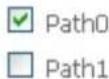
Select DSL Latency
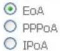
Select DSL Link Type (EoA is for PPPoE, IPoE, and Bridge.)
Select Connection Mode

text_image
Default Mode - Single service over one connection VLAN MUX Mode - Multiple Vlan service over one connectionEncapsulation Mode:

Service Category:

Select IP QoS Scheduler Algorithm
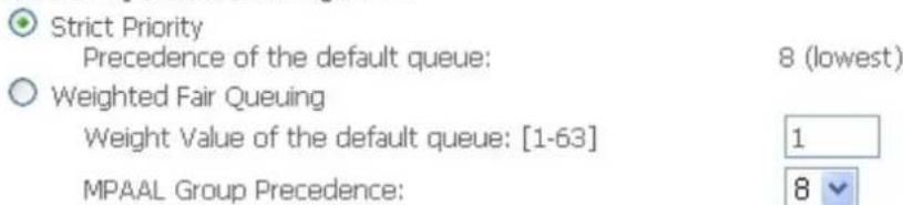
text_image
Strict Priority Precedence of the default queue: 8 (lowest) Weighted Fair Queuing Weight Value of the default queue: [1-63] 1 MPAAL Group Precedence: 8
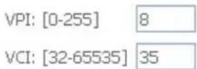
VCI/VPI: enter the VCI/VPI from your ISP.
Select DSL Link Type: select the link type (protocol), EOA, PPPoA, IPoA.
Select Connection Mode:
① Default Mode: this mode only allows single service over one connection.
① VLAN MUX Mode: this mode allows multiple services over one PVC.
The two modes can be different in WAN service configuration. And PPPoA and IPoA do not use Ethernet frames for data transfer so they cannot work with VLAN Mux feature. Thus, Connection Mode Parameter will be hided if you select PPPoA or IPoA in Link Type.
Encapsulation Mode: select the encapsulation mode from the drop-down menu according to the link Type.
Service Category: select the service category from the drop-down menu to determine your service category.
① UBR without PCR: UBR(Unspecified Bit Rate), PCR(Peak cell Rate)
UBR is a kind of QoS, which doesn't provide assurance about the cell latency, the bit loss rate etc, it is a best-effort service.
Service Category:
UBR Without PCR
Select IP QoS Scheduler Algorithm
Strict Priority
Precedence of the default queue:
8 (lowest)
Weighted Fair Queuing
Weight Value of the default queue: [1-63]
MPAAL Group Precedence:

Select IP QoS Schedule Algorithm: select the Schedule Algorithm, SP(Strict Priority), always sends the packets with the highest priority, WFQ(Weighted Fair Queuing), an automatically bandwidth adjusting method, sharing the available bandwidth when congestion happens, the bandwidth is assigned according to the priority and the weight value. Turn to the Quality of Service > Queue Config section for more information.
Precedence of the default queue: default 8(lowest)
Service Category:
UBR Without PCR

Select IP QoS Scheduler Algorithm
○ Strict Priority
Precedence of the default queue:
8 (lowest)
Weighted Fair Queuing
Weight Value of the default queue: [1-63]
MPAAL Group Precedence:
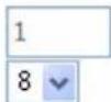
Weight Value of default queue: enter the value, 1-63, the highest is 63.
MPAAL Group Precedence: select the precedence identification, 1-8, the highest is 1.
① UBR with PCR/ CBR(Constant Bit Rate)
UBR is a kind of service providing constant rate service, is idea for timely and fixed bandwidth needed service.
Service Category: Peak Cell Rate: [cells/s]
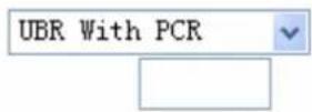
Peak Cell Rate: enter Peak Cell Rate.
① Non Realtime VBR/ Realtime VBR(Variable Bit Rate)
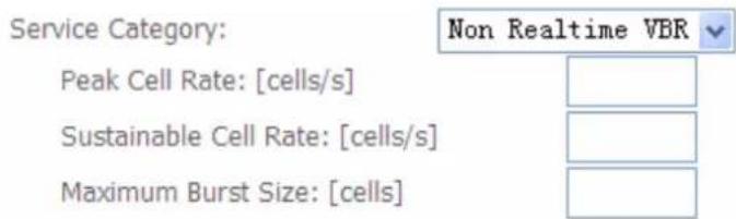
VBR is a kind of service providing some assurance about latency and bit loss rate and is often associated with video and time sensitive service. NR-VBR allows more time delay to R-VBR.
text_image
Service Category: Non Realtime VBR Peak Cell Rate: [cells/s] Sustainable Cell Rate: [cells/s] Maximum Burst Size: [cells]Enter Peak Cell Rate, Sustainable Cell Rate and Maximum Burst Rate.
Click Apply to apply the WAN interface.
DSL ATM Interface Configuration
Choose Add, or Remove to configure DSL ATM interfaces.
| Interface | Vpi | Vci | DSL Latency | Category | Link Type | Connection Mode | IP QoS | Scheduler Alg | Queue Weight | Group Precedence | Remove |
| atm0 | 8 | 35 | Path0 | UBR | EoA | DefaultMode | Enabled | SP |

Check the remove checkbox, then press Remove to delete it only if this interface are not used by a WAN Service, if it is used by a WAN service, first remove the WAN service, then turn back to remove the interface.
Don't feel confused, it will remind you by the following prompt window.
DSL Interface Remove Error
You CANNOT remove this DSL Interface if it is used by a WAN Service. You need to remove the WAN Service before you can remove this DSL interface.
Click on "Back" button to give it an another try.
Or
Click on "Reboot Router" button to reboot the Broadband Router and try it again.

Now follow the above steps, we set two ATM WAN interfaces for future illustration, one is of DefaultMode, and one is of VlanMuxMode.
DSL ATM Interface Configuration
Choose Add, or Remove to configure DSL ATM interfaces.
| Interface | Vpi | Vci | DSL Latency | Category | Link Type | Connection Mode | IP QoS | Scheduler Alg | Queue Weight | Group Precedence | Remove |
| atm0 | 8 | 35 | Path0 | UBR | EoA | DefaultMode | Enabled | SP | |||
| atm1 | 1 | 35 | Path0 | UBR | EoA | VlanMuxMode | Enabled | SP |
Add Remove
WAN Service
WAN Service allows you to configure one or more services over one interface (connection). The following is the WAN Service listing table. Your configured WAN service will be listed here.
Wide Area Network (WAN) Service Setup
Choose Add, Remove or Edit to configure a WAN service over a selected interface.
| Interface | Description | Type | Vlan8021p | VlanMuxId | Igmp | NAT | Firewall | Remove | Edit |

Default Connection mode
Select the interface which is a Default mode connection configured in WAN Service, here for example, in the following, atm0/(0_8_35) is a Default mode connection.
Click Add to create one WAN service.
WAN Service Interface Configuration
Select a layer 2 interface for this service
Note: For ATM interface, the descriptor string is (portId_vpi_vci)
For PTM interface, the descriptor string is (portId_high_low)
Where portId=0 --> DSL Latency PATH0
    portId=1 --> DSL Latency PATH1
    portId=4 --> DSL Latency PATH0&1
    low =0 --> Low PTM Priority not set
    low =1 --> Low PTM Priority set
    high =0 --> High PTM Priority not set
    high =1 --> High PTM Priority set

Select the interface, the listed interfaces are the one you configured in WAN interface section. Click Next to further configure.
WAN Service Configuration
Select WAN service type:
PPP over Ethernet (PPPoE)
IP over Ethernet
Bridging
Enter Service Description: pppoe_0_8_35
Back Next
Select WAN service type: select the protocol advised by your ISP, here select PPPoE.
Enter Service Description: user-defined description.
Click Next to go on.
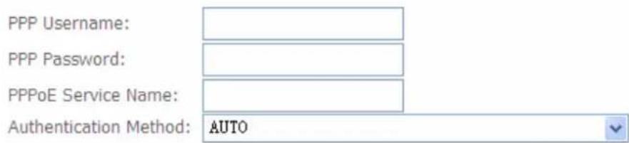
PPP Username and Password
PPP usually requires that you have a user name and password to establish your connection. In the boxes below, enter the user name and password that your ISP has provided to you.
text_image
PPP Username: PPP Password: PPPoE Service Name: Authentication Method: AUTOEnable Firewall
Enable Fullcone NAT
☐ Dial on demand (with idle timeout timer)
□ enable manual MTU set
PPP IP extension
Use Static IPv4 Address
Enable PPP Debug Mode
Enable KeepAlive
Max Fail [0-100]: 0 times
Bridge PPPoE Frames Between WAN and Local Ports
Multicast Proxy
Enable IGMP Multicast Proxy

PPP Username: enter ISP account.
PPP Password: enter the password.
PPPoE Service name: user-defined name.
Authentication method: select the authentication method.
Enable Fullcone NAT: enable or disable fullcone NAT. Fullcone is a kind of NAT, in this mode, all requests from the same internal IP address and port are mapped to the same external IP address
and port. Furthermore, any external host can send a packet to the internal host, by sending a packet to the mapped external address.
Note: In PPPoE connection, NAT is enabled by default, you can determine whether to enable Fullcone NAT. And while you disabled Fullcone NAT and only use NAT, the default NAT type is Port Restricted cone NAT. Of Port-Restricted cone NAT, the restriction includes port numbers. Specifically, an external host can send a packet, with source IP address X and source port P, to the internal host only if the internal host had previously sent a packet to IP address X and port P
Dial on demand: enable or disable, if you want to Dial on demand, enable this function.
Inactivity timeout: available when you enable Dial on demand function. Enter the Inactivity timeout interval.
PPP IP extension: After enabling it, it allows only one computer on the LAN side to browse the internet. The public IP address assigned by the remote, will be applied to the host through DHCP (DHCP server on CPE can only assign one IP address). And, NAT and Firewall feature will be disabled when this option is selected.
Use Static IPv4 Address: enable to use the static IPv4 address, else to get an IPv4 address automatically.
IPv4 Address: available when enabled to use IPv4 address, and please enter the Static IPv4 address if you enable Static IP Address.
Enable PPPoE Debug mode: check whether to enable this function, it is used to debug PPPoE link, and the debug message will be seen in System log.
Enable KeepAlive: If enabled, CPE will send PPPoE Echo message to the server periodically.
KeepAlive Time: available when you enabled KeepAlive above, then enter the time cycle for CPE to send PPPoE Echo message to the server periodically (0-30 min).
Max Fail: enter the max fail times. It is a number used to determine when PPPoE disconnects. For example, suppose the number is 3, then if the router fails to receive any echo reply from the server for 3 times, PPPoE disconnects automatically.
Bridge PPPoE Frame between WAN and Local Ports: check whether to enable this function. It allows PC in LAN to set up its own PPP link, or the PC will access internet via the PPP link in WAN port.
Enable IGMP Multicast Proxy: check whether to enable this function. IGMP (Internet Group Management Protocol) Proxy intercept the IGMP request from Clients and forward it to the router after some dealings.
Click Next to go on to the Default Gateway setting.
Routing -- Default Gateway
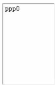
Default gateway interface list can have multiple WAN interfaces served as system default gateways but only one will be used according to the priority with the first being the higest and the last one the lowest priority if the WAN interface is connected. Priority order can be changed by removing all and adding them back in again.
Selected Default Gateway Interfaces
text_image
ppp0
Available Routed WAN Interfaces

natural_image
Blank white image with a thin gray border (no text or symbols)
Click Next to go on to set DNS Server.
DNS Server Configuration
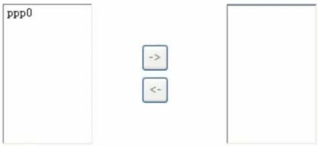
Select DNS Server Interface from available WAN interfaces OR enter static DNS server IP addresses for the system. In ATM mode, if only a single PVC with IPoA or static IPoE protocol is configured, Static DNS server IP addresses must be entered.
DNS Server Interfaces can have multiple WAN interfaces served as system dns servers but only one will be used according to the priority with the first being the higest and the last one the lowest priority if the WAN interface is connected. Priority order can be changed by removing all and adding them back in again.
Select DNS Server Interface from available WAN interfaces:
Selected DNS Server Interfaces
Available WAN Interfaces
text_image
ppp0 -> <-Use the following Static DNS IP address:
Primary DNS server:
Secondary DNS server:
Select the DNS Server or enter the one yourself.
Click Next to go on. Then you can view the information about your settings.
WAN Setup - Summary
Make sure that the settings below match the settings provided by your ISP.
| Connection Type: | PPPoE |
| NAT: | Enabled |
| Full Cone NAT: | Enabled |
| Firewall: | Disabled |
| IGMP Multicast: | Disabled |
| Quality Of Service: | Enabled |
Click "Apply/Save" to have this interface to be effective. Click "Back" to make any modifications.
Back Apply/Save
If you confirm about the above settings, click Apply/Save to apply your settings. Then the service will be listed as follows.
Wide Area Network (WAN) Service Setup
Choose Add, Remove or Edit to configure a WAN service over a selected interface.
| Interface | Description | Type | Vlan8021p | VlanMuxId | Igmp | NAT | Firewall | Remove | Edit |
| ppp0 | pppoe_0_8_35 | PPPoE | N/A | N/A | Disabled | Enabled | Disabled |

If you don not need the service, select the item you want to remove, check the checkbox, then press Remove, it will be OK.
Here the corresponding WAN interface and WAN Service have been configured, if it is OK, you can access the internet. You can go to Device Info>WAN or Summary to view the WAN connection information.
WAN Info
| Interface | Description | Type | VlanMuxId | Igmp | NAT | Firewall | Status | IPv4 Address |
| ppp0 | pppoe_0_8_35 | PPPoE | Disabled | Disabled | Enabled | Enabled | Connected | 111.251.230.225 |
BILLION
Wireless-N ADSL2+ Firewall Router
Powering communications with Security
Device Info
Summary
WAN
Statistics
Route
ARP
DHCP
Quick Start
Advanced Setup
Wireless
Diagnostics
Management
Device Info
| Model Name: | BiPAC 7700N |
| Software Version: | B038_K82_GH-00-1659 |
| Bootloader (CFE) Version: | 1.0.37-106.5 |
| DSL PHY and Driver Version: | A2pD030g.d22j |
| Wireless Driver Version: | 5.60.120.3.cpe4.406.0 |
This information reflects the current status of your WAN connection.
| Line Rate - Upstream (Kbps): | 1083 |
| Line Rate - Downstream (Kbps): | 23541 |
| LAN IPv4 Address: | 192.168.1.254 |
| MAC Address: | 00:04:ed:77:00:01 |
| Default Gateway: | ppp0 |
| Primary DNS Server: | 168.95.192.1 |
| Secondary DNS Server: | 168.95.1.1 |
| Date/Time: | Mon Jan 17 10:20:23 |
Copyright @ Billion Electric Co., Ltd. All rights reserved.
IP over Ethernet
WAN Service Configuration
Select WAN service type:
○ PPP over Ethernet (PPPoE)
IP over Ethernet
Bridging
Enter Service Description: ipoe_0_8_35

Select WAN service type: select the protocol advised by your ISP, here select IP over Ethernet.
Enter Service Description: user-defined description.
Click Next to go to next step.
WAN IP Settings
Enter information provided to you by your ISP to configure the WAN IP settings.
Notice: If "Obtain an IP address automatically" is chosen, DHCP will be enabled for PVC in IPoE mode.
If "Use the following Static IP address" is chosen, enter the WAN IP address, subnet mask and interface gateway.
Obtain an IP address automatically
Option 60 Vendor ID:
Option 61 IAID:
Option 61 DUID:
Option 125:
Disable
(8 hexadecimal digits)
(hexadecimal digit)
Enable
Use the following Static IP address:
WAN IP Address:
WAN Subnet Mask:
WAN gateway IP Address:
Here two modes are supported for users to deal with the IP and DNS. You can select obtain automatically or manually input the information according to your ISP.
Obtain an IP address automatically: check whether to enable this function.
Option 60 Vendor ID: Enter the associated information by your ISP. This option is used by DHCP clients to optionally identify the vendor type and configuration of a DHCP client. The information is a string of n octets, interpreted by servers. Vendors may choose to define specific vendor class identifiers to convey particular configuration or other identification information about a client.
Option 61 IAID: Enter the associated information provided by your ISP. You should input 8 hexadecimal numbers.
Option 61 DUID: Enter the associated information provided by your ISP. You should input hexadecimal number(s).
Option 125: Option 125 is a complementary standard of DHCP protocol, it is used to encapsulate option 125 message into DHCP offer packet before forward it to clients. After the clients receive the packet, it check the option 125 field in the packet with the prestored message, if it is matched, then the client accepts this offer, otherwise it will be abandoned. Check Enable or Disable this function. Default setting is Disable.
Use the following Static IP address: enable to set the IP address from ISP yourself.
WAN IP Address: Enter your IP address to the device provided by your ISP. If Fixed IP address is selected in the IPv4 Protocol field, default value 0.0.0.0 will display in this field.
WAN Subnet Mask: Enter your submask to the device provided by your ISP.
WAN gateway IP Address: Enter your gateway IP address to the device provided by your ISP.
Note: If you don't know well about the DHCP Option, you can leave it empty or leave it as default.
Click Next to go to next step.
Network Address Translation Settings
Network Address Translation (NAT) allows you to share one Wide Area Network (WAN) IP address for multiple computers on your Local Area Network (LAN).
Enable NAT
Enable Fullcone NAT
Enable Firewall
IGMP Multicast
Enable IGMP Multicast
Enable NAT: The NAT (Network Address Translation) feature allows multiple users to access the Internet through a single IP account by sharing the single IP address. If users on your LAN have their own public IP addresses to access the Internet, NAT function can be disabled. When enabled, a Fullcone NAT parameter will appear, you can determine whether to enable Fullcone NAT. While only NAT enabled, the default NAT type Port-Restricted cone NAT will be used. For detail, please turn to page 47 for help.
Enable Firewall: Check/uncheck this item to enable/disable firewall function.
Enable IGMP Multicast: IGMP (Internet Group Membership Protocol) is a protocol used by IP hosts to report their multicast group memberships to any immediately neighboring multicast routers. Check this item to enable IGMP multicast on that WAN interface for multicast forwarding.
Click Next to go to set default gateway.
Routing -- Default Gateway
Default gateway interface list can have multiple WAN interfaces served as system default gateways but only one will be used according to the priority with the first being the higest and the last one the lowest priority if the WAN interface is connected. Priority order can be changed by removing all and adding them back in again.
Selected Default Gateway Interfaces
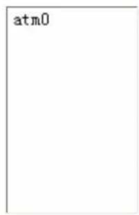
text_image
atm0
Available Routed WAN Interfaces

natural_image
Blank white image with no visible content, text, or symbols
Click Next to go on to set DNS.
DNS Server Configuration
Select DNS Server Interface from available WAN interfaces OR enter static DNS server IP addresses for the system. In ATM mode, if only a single PVC with IPoA or static IPoE protocol is configured, Static DNS server IP addresses must be entered.
DNS Server Interfaces can have multiple WAN interfaces served as system dns servers but only one will be used according to the priority with the first being the higest and the last one the lowest priority if the WAN interface is connected. Priority order can be changed by removing all and adding them back in again.
Select DNS Server Interface from available WAN interfaces:
Selected DNS Server Interfaces
Available WAN Interfaces
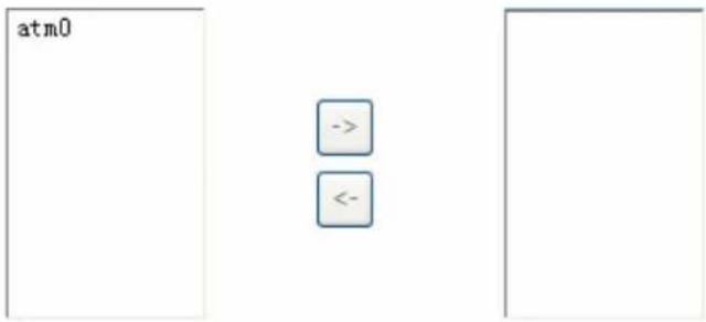
text_image
atm0 -> <-Use the following Static DNS IP address:
Primary DNS server:

Secondary DNS server:

Select DNS server interface from available WAN interfaces, or you can set the one yourself by select Use the following Static DNS IP address and enter the appropriate ones.
Click Next to go on to check the settings.
WAN Setup - Summary
Make sure that the settings below match the settings provided by your ISP.
| Connection Type: | IPoE |
| NAT: | Enabled |
| Full Cone NAT: | Disabled |
| Firewall: | Disabled |
| IGMP Multicast: | Disabled |
| Quality Of Service: | Disabled |
Click "Apply/Save" to have this interface to be effective. Click "Back" to make any modifications.

Click Apply/Save to apply your settings.
Bridging
WAN Service Configuration
Select WAN service type:
○ PPP over Ethernet (PPPoE)
IP over Ethernet
Bridging
Enter Service Description: br_0_8_35

Select WAN service type: select the protocol advised by your ISP, here select Bridging. Enter Service Description: user-defined description.
Click Next to go to next step.
WAN Setup - Summary
Make sure that the settings below match the settings provided by your ISP.
| Connection Type: | Bridge |
| NAT: | Disabled |
| Full Cone NAT: | Disabled |
| Firewall: | Disabled |
| IGMP Multicast: | Not Applicable |
| Quality Of Service: | Disabled |
Click "Apply/Save" to have this interface to be effective. Click "Back" to make any modifications.

Click Apply/Save to apply your settings.
VLAN MUX Connection Mode
It is similar to Default Connection in configuration. Select the interface which is a VLAN MUX mode connection configured in WAN Service, here for example, in the following, atm1/(0_1_35) is a VLAN MUX mode connection.
select interface(VLAN MUX mode).
WAN Service Interface Configuration
Select a layer 2 interface for this service
Note: For ATM interface, the descriptor string is (portId_vpi_vci)
For PTM interface, the descriptor string is (portId_high_low)
Where portId=0 --> DSL Latency PATH0
    portId=1 --> DSL Latency PATH1
    portId=4 --> DSL Latency PATH0&1
    low =0 --> Low PTM Priority not set
    low =1 --> Low PTM Priority set
    high =0 --> High PTM Priority not set
    high =1 --> High PTM Priority set
atm1/(0_1_35)
Back Next
Click Next to go on to next step.
WAN Service Configuration
Select WAN service type:
PPP over Ethernet (PPPoE)
IP over Ethernet
Bridging
Enter Service Description: pppoe_0_1_35
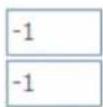
For tagged service, enter valid 802.1P Priority and 802.1Q VLAN ID.
For untagged service, set -1 to both 802.1P Priority and 802.1Q VLAN ID.
Enter 802.1P Priority [0-7]:
Enter 802.1Q VLAN ID [0-4094]:
Select WAN service type: select the protocol, PPPoE, IP over Internet, Bridge.
Enter Service Description: user-defined description.
Enter 802.1P Priority: It indicates the frame priority level from 0 (lowest) to 7 (highest), which can
be used to prioritize different classes of traffic (voice, video, data, etc). Enter the priority identification, tagged:0-7, untagged:-1.
Enter 802.1Q VLAN ID: It is a parameter to specify the VLAN which the frame belongs. Enter the VLAN ID identification, tagged: 0-4094, untagged:-1.
You can leave 802.1P Priority and 802.1Q VLAN ID as default setting,-1, means untagged, in this mode, the vlan tag header will not be contained, but if you want to allow one service for the specific vlan, here you should set the two parameters, the vlan tag header will be contained.
The following steps are similar to Default Connection settings, for help turn to Default Connection settings.
Take an example, let's look at a scenario in which 1 PPPoE and 1 Bridge service needed by user. In the above page, click Next to set WAN service parameters.
PPP Username and Password
PPP usually requires that you have a user name and password to establish your connection. In the boxes below, enter the user name and password that your ISP has provided to you.
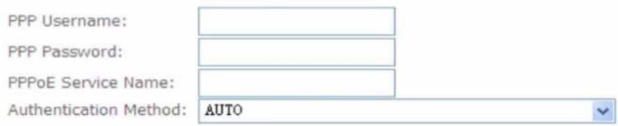
text_image
PPP Username: PPP Password: PPPoE Service Name: Authentication Method: AUTOEnable Firewall
Enable Fullcone NAT
☐ Dial on demand (with idle timeout timer)
□ enable manual MTU set
PPP IP extension
Use Static IPv4 Address
Enable PPP Debug Mode
Enable KeepAlive
Max Fail [0-100]: 0 times
Bridge PPPoE Frames Between WAN and Local Ports
Multicast Proxy
Enable IGMP Multicast Proxy

Click Next to set the default gateway of this connection.
Routing -- Default Gateway
Default gateway interface list can have multiple WAN interfaces served as system default gateways but only one will be used according to the priority with the first being the higest and the last one the lowest priority if the WAN interface is connected. Priority order can be changed by removing all and adding them back in again.
Selected Default Gateway Interfaces
ppp0.1

Available Routed WAN Interfaces

natural_image
Blank white image with a thin gray border (no text, symbols, or markings)
Click Next to set the DNS.
DNS Server Configuration
Select DNS Server Interface from available WAN interfaces OR enter static DNS server IP addresses for the system. In ATM mode, if only a single PVC with IPoA or static IPoE protocol is configured, Static DNS server IP addresses must be entered.
DNS Server Interfaces can have multiple WAN interfaces served as system dns servers but only one will be used according to the priority with the first being the higest and the last one the lowest priority if the WAN interface is connected. Priority order can be changed by removing all and adding them back in again.
Select DNS Server Interface from available WAN interfaces:
Selected DNS Server Interfaces
Available WAN Interfaces
ppp0.1


natural_image
Blank white image with a thin gray border (no text or symbols)Use the following Static DNS IP address:
Primary DNS server:

Secondary DNS server:

Click Next to view the information you have set to the connection, then click Apply/Save to save your settings.
WAN Setup - Summary
Make sure that the settings below match the settings provided by your ISP.
| Connection Type: | PPPoE |
| NAT: | Enabled |
| Full Cone NAT: | Enabled |
| Firewall: | Disabled |
| IGMP Multicast: | Disabled |
| Quality Of Service: | Enabled |
Click "Apply/Save" to have this interface to be effective. Click "Back" to make any modifications.
Back
Apply/Save
Then you can see the PPPoE connection is listed below. Here it is just one service over atm1/(0_1_35).
Wide Area Network (WAN) Service Setup
Choose Add, Remove or Edit to configure a WAN service over a selected interface.
| Interface | Description | Type | Vlan8021p | VlanMuxId | Igmp | NAT | Firewall | Remove | Edit |
| ppp0.1 | pppoe_0_1_35 | PPPoE | N/A | N/A | Disabled | Enabled | Disabled | Edit |

Then we can again set a Bridging connection over atm1/(0_1_35) interface. Click Add in the above page, the atm1/(0_1_35) also is listed for selection to add services.
WAN Service Interface Configuration
Select a layer 2 interface for this service
Note: For ATM interface, the descriptor string is (portId_vpi_vci)
For PTM interface, the descriptor string is (portId_high_low)
Where portId=0 --> DSL Latency PATH0
    portId=1 --> DSL Latency PATH1
    portId=4 --> DSL Latency PATH0&1
    low =0 --> Low PTM Priority not set
    low =1 --> Low PTM Priority set
    high =0 --> High PTM Priority not set
    high =1 --> High PTM Priority set
Continue clicking Next to select Bridging connection type.
WAN Service Configuration
Select WAN service type:
○ PPP over Ethernet (PPPoE)
IP over Ethernet
Bridging
Enter Service Description: br_0_1_35
For tagged service, enter valid 802.1P Priority and 802.1Q VLAN ID.
For untagged service, set -1 to both 802.1P Priority and 802.1Q VLAN ID.
Enter 802.1P Priority [0-7]:
Enter 802.1Q VLAN ID [0-4094]:
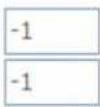

Click Next to make sure your settings below match the settings provided by your ISP. And Click Apply/Save to save your settings.
WAN Setup - Summary
Make sure that the settings below match the settings provided by your ISP.
| Connection Type: | Bridge |
| NAT: | Disabled |
| Full Cone NAT: | Disabled |
| Firewall: | Disabled |
| IGMP Multicast: | Not Applicable |
| Quality Of Service: | Enabled |
Click "Apply/Save" to have this interface to be effective. Click "Back" to make any modifications.

The connections over one PVC as follows:
Wide Area Network (WAN) Service Setup
Choose Add, Remove or Edit to configure a WAN service over a selected interface.
| Interface | Description | Type | Vlan8021p | VlanMuxId | Igmp | NAT | Firewall | Remove | Edit |
| atm1.2 | br_0_1_35 | Bridge | N/A | N/A | Disabled | Disabled | Disabled | Edit | |
| ppp0.1 | pppoe_0_1_35 | PPPoE | N/A | N/A | Disabled | Enabled | Disabled | Edit |

This screen is the interface we set previous, here used for understanding.
DSL ATM Interface Configuration
Choose Add, or Remove to configure DSL ATM interfaces.
| Interface | Vpi | Vci | DSL Latency | Category | Link Type | Connection Mode | IP QoS | Scheduler Alg | Queue Weight | Group Precedence | Remove |
| atm0 | 8 | 35 | Path0 | UBR | EoA | DefaultMode | Enabled | SP | |||
| atm1 | 1 | 35 | Path0 | UBR | EoA | VlanMuxMode | Enabled | SP |

The below is WAN connection status, here you can see clearly the multiple services over one PVC.
WAN Info 114.25.180.239
| Interface | Description | Type | VlanMuxId | Igmp | NAT | Firewall | Status | IPv4 Address |
| atm1.2 | br_0_1_35 | Bridge | Disabled | Disabled | Disabled | Disabled | Connected | 0.0.0.0 |
| ppp0.1 | pppoe_0_1_35 | PPPoE | Disabled | Disabled | Enabled | Disabled | Connected | 114.25.180.239 |
See from the above diagrams, we have set one PVC, it is VPI/VCI 1/35. But we have set two services on the same PVC, they are bridging and PPPoE services.
While in contrast to Default connection mode, one PVC can only hold one service, if you want to more than one service over one PVC, you should apply from your ISP more PVCs to meet your needs.
LAN - Local Area Network
A Local Area Network (LAN) is a shared communication system network where many computers are connected. This type of network is area defined and is usually limited to a confined region within a building or just within the same storey of a building.
Local Area Network (LAN) Setup
Configure the DSL Router IP Address and Subnet Mask for LAN interface. GroupName Default
| IP Address: | 192.168.1.254 |
| Subnet Mask: | 255.255.255.0 |
Enable IGMP Snooping
Enable LAN side firewall
Disable DHCP Server
Enable DHCP Server
| Start IP Address: | 192.168.1.1 | |
| End IP Address: | 192.168.1.20 | |
| Leased Time : | 24 | Hour |
| 0 | Minute |
Static IP Lease List: (A maximum 32 entries can be configured)
| MAC Address | IP Address | Remove |
| Add Entries | Remove Entries | |
○ Enable DHCP Server Relay
DHCP Server IP Address:
Configure the second IP Address and Subnet Mask for LAN interface
Apply/Save
Parameters
Group Name: here group refers to the group you set in Interface Grouping section, you can set the parameters for the specific group. Select the group by the drop-down box. For more information please refer to Interface Grouping of this manual.
IP address: the IP address of the router. Default is 192.168.1.254.
Subnet Mask: the default Subnet mask on the router.
Enable IGMP Snooping: Enable or disable the IGMP Snooping function. Without IGMP snooping, multicast traffic is treated in the same manner as broadcast traffic - that is, it is forwarded to all ports. With IGMP snooping, multicast traffic of a group is only forwarded to ports that have members of that group."
When enabled, you will see two modes:
① Standard Mode: In standard mode, multicast traffic will flood to all bridge ports when no client subscribes to a multicast group.
① Blocking Mode: In blocking mode, the multicast data will be blocked when there are no client subscribes to a multicast group, it won't flood to the bridge ports.
Enable LAN Side Firewall: Blocking all service on the LAN side. After activating it, the user on the LAN side can't access CPE any more. But, you still can enjoy the internet service on the LAN side. But Note that by default the remote access (HTTP service in WAN side, you can go to Service to enable remote access service) is disabled, thus if you enable LAN Side Firewall, then in this case, you can have no access to manage this CPE through both LAN and WAN, the only method you can adopt is to restore the CPE to default setting.
DHCP Server
You can disable or enable the DHCP (Dynamic Host Configuration Protocol) server or enable the router's DHCP relay functions. The DHCP protocol allows your router to dynamically assign IP addresses to PCs on your network if they are configured to obtain IP addresses automatically.
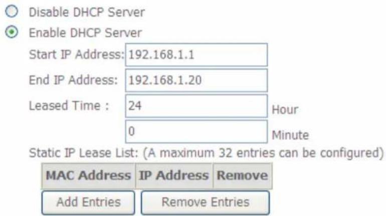
text_image
Disable DHCP Server Enable DHCP Server Start IP Address: 192.168.1.1 End IP Address: 192.168.1.20 Leased Time : 24 Hour 0 Minute Static IP Lease List: (A maximum 32 entries can be configured) MAC Address IP Address Remove Add Entries Remove Entries
text_image
Enable DHCP Server Relay DHCP Server IP Address:① Disable DHCP Server: Disable the DHCP Server function.
① Enable DHCP Server: Enable the DHCP function, enter the information wanted. Here as default.
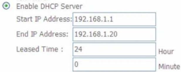
text_image
Enable DHCP Server Start IP Address: 192.168.1.1 End IP Address: 192.168.1.20 Leased Time : 24 Hour 0 MinuteStart IP Address: the start IP address of the range the DHCP Server used to assign to the Clients.
End IP Address: the end IP address f the range the DHCP Server used to assign to the Clients.
Leased Time: Set the leased time for each DHCP Client.
Static IP List:
The specified IP will be assigned to the corresponding MAC Address listed in the following table when DHCP Server assigns IP Addresses to Clients.
Static IP Lease List: (A maximum 32 entries can be configured)
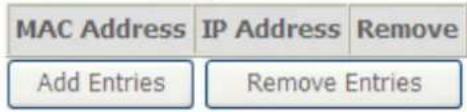
text_image
MAC Address IP Address Remove Add Entries Remove EntriesPress Add to the Static IP List.
DHCP Static IP Lease
Enter the Mac address and Static IP address then click "Apply/Save".
MAC Address:
IP Address:
Apply/Save
Enter the MAC Address, IP Address and Host Name, then click Apply to confirm your settings.
① DHCP Server Relay
○ Enable DHCP Server Relay
DHCP Server IP Address:

If you check DHCP Relay then you must enter the IP address of the DHCP server which assigns an IP address back to the DHCP client in the LAN. Use this function only if advised to do so by your network administrator or ISP.
Configure the second IP Address and Subnet Mask for LAN interface:
This function allows the creation of multiple virtual IP interfaces on this router. It helps to connect two or more local networks to the ISP or remote node.
Configure the second IP Address and Subnet Mask for LAN interface
IP Address:
Subnet Mask:
IP Address: Specify an IP address on this virtual interface.
Netmask: Specify a subnet mask on this virtual interface.
Click Apply to apply your settings.
NAT
NAT (Network Address Translation) feature translates a private IP to a public IP, allowing multiple users to access the Internet through a single IP account, sharing the single IP address. It is a natural firewall for the private network.
Virtual Servers
In TCP/IP and UDP networks a port is a 16-bit number used to identify which application program (usually a server) incoming connections should be delivered to. Some ports have numbers that are pre-assigned to them by the IANA (the Internet Assigned Numbers Authority), and these are referred to as “well-known ports”. Servers follow the well-known port assignments so clients can locate them.
If you wish to run a server on your network that can be accessed from the WAN (i.e. from other machines on the Internet that are outside your local network), or any application that can accept incoming connections (e.g. Peer-to-peer/P2P software such as instant messaging applications and P2P file-sharing applications) and are using NAT (Network Address Translation), then you will usually need to configure your router to forward these incoming connection attempts using specific ports to the PC on your network running the application. You will also need to use port forwarding if you want to host an online game server.
The reason for this is that when using NAT, your publicly accessible IP address will be used by and point to your router, which then needs to deliver all traffic to the private IP addresses used by your PCs. Please see the WAN configuration section of this manual for more information on NAT.
The device can be configured as a virtual server so that remote users accessing services such as Web or FTP services via the public (WAN) IP address can be automatically redirected to local servers in the LAN network. Depending on the requested service (TCP/UDP port number), the device redirects the external service request to the appropriate server within the LAN network.
This part is only available when NAT is enabled.
NAT -- Virtual Servers Setup
Virtual Server allows you to direct incoming traffic from WAN side (identified by Protocol and External port) to the Internal server with private IP address on the LAN side. The Internal port is required only if the external port needs to be converted to a different port number used by the server on the LAN side. A maximum 32 entries can be configured.

| Server Name | External Port Start | External Port End | Protocol | Internal Port Start | Internal Port End | Server IP Address | WAN Interface | Remove |
Click Add to add new rules.
The following configuration page will appear to let you configure.
NAT -- Virtual Servers
Select the service name, and enter the server IP address and click "Apply/Save" to forward IP packets for this service to the specified server. NOTE: The "Internal Port End" cannot be modified directly. Normally, it is set to the same value as "External Port End". However, if you modify "Internal Port Start", then "Internal Port End" will be set to the same value as "Internal Port Start".
Remaining number of entries that can be configured:32
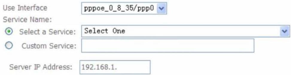
text_image
Use Interface pppoe_0_8_35/ppp0 Service Name: Select a Service: Select One Custom Service: Server IP Address: 192.168.1.Apply/Save
| External Port Start | External Port End | Protocol | Internal Port Start | Internal Port End | ||
| TCP✓ | ||||||
| TCP✓ | ||||||
| TCP✓ | ||||||
| TCP✓ | ||||||
| TCP✓ | ||||||
| TCP✓ | ||||||
| TCP✓ | ||||||
| TCP✓ | ||||||
| TCP✓ | ||||||
| TCP✓ | ||||||
| TCP✓ | ||||||
| TCP✓ | ||||||
Apply/Save
Use Interface: select from the drop-down menu the interface you want the virtual server(s) applies to.
Server Name:
i Select a Service: select the server name from the drop-down menu.
① Custom Service: it is a kind of service to let users customize the service they want. Enter the user-defined service name here. It is a parameter only available when users select Custom Service in the above parameter.
Server IP Address: Enter your server IP Address here.
External Port
① Start: Enter a port number as the external starting number for the range you want to give
access to internal network.
① End: Enter a port number as the external ending number for the range you want to give access to internal network.
Internal Port
① Start: Enter a port number as the internal staring number.
① End: Here it will generate automatically according to the End port number of External port and can't be modified.
Protocol: select the protocol this service used: TCP/UDP, TCP, UDP.
Note: The "Internal Port End" cannot be modified directly. Normally, it is set to the same value as "External Port End". However, if you modify "Internal Port Start", then "Internal Port End" will be set to the same value as "Internal Port Start".
Set up
- Select a Server Name from the drop-down menu, then the port will automatically appear, modify some as you like, or you can just leave it as default. Remember to enter your server IP Address.
NAT -- Virtual Servers
Select the service name, and enter the server IP address and click "Apply/Save" to forward IP packets for this service to the specified server. NOTE: The "Internal Port End" cannot be modified directly. Normally, it is set to the same value as "External Port End". However, if you modify "Internal Port Start", then "Internal Port End" will be set to the same value as "Internal Port Start".
Remaining number of entries that can be configured:32
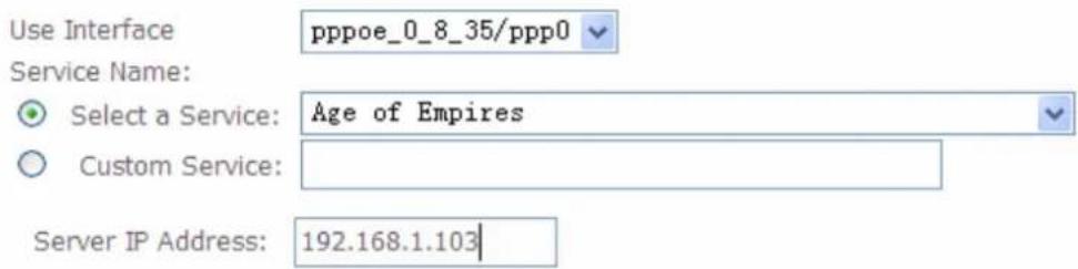
text_image
Use Interface pppoe_0_8_35/ppp0 Service Name: Select a Service: Age of Empires Custom Service: Server IP Address: 192.168.1.103Apply/Save
| External Port Start | External Port End | Protocol | Internal Port Start | Internal Port End | ||
| 47624 | 47624 | TCP | 47624 | 47624 | ||
| 6073 | 6073 | TCP | 6073 | 6073 | ||
| 2300 | 2400 | TCP | 2300 | 2400 | ||
| 2300 | 2400 | UDP | 2300 | 2400 | ||
| TCP | ||||||
| TCP | ||||||
| TCP | ||||||
| TCP | ||||||
| TCP | ||||||
| TCP | ||||||
| TCP | ||||||
| TCP | ||||||
| TCP | ||||||
Apply/Save
- Press Apply/Save to conform, and the items will be list as below.
NAT -- Virtual Servers Setup
Virtual Server allows you to direct incoming traffic from WAN side (identified by Protocol and External port) to the Internal server with private IP address on the LAN side. The Internal port is required only if the external port needs to be converted to a different port number used by the server on the LAN side. A maximum 32 entries can be configured.

| Server Name | External Port Start | External Port End | Protocol | Internal Port Start | Internal Port End | Server IP Address | WAN Interface | Remove |
| Age of Empires | 47624 | 47624 | TCP | 47624 | 47624 | 192.168.1.103 | ppp0 | |
| Age of Empires | 6073 | 6073 | TCP | 6073 | 6073 | 192.168.1.103 | ppp0 | |
| Age of Empires | 2300 | 2400 | TCP | 2300 | 2400 | 192.168.1.103 | ppp0 | |
| Age of Empires | 2300 | 2400 | UDP | 2300 | 2400 | 192.168.1.103 | ppp0 |
Remove
If you don't need a specified Server, you can remove it. Check the check box beside the item you want to remove, then press Remove, it will be OK.
NAT -- Virtual Servers Setup
Virtual Server allows you to direct incoming traffic from WAN side (identified by Protocol and External port) to the Internal server with private IP address on the LAN side. The Internal port is required only if the external port needs to be converted to a different port number used by the server on the LAN side. A maximum 32 entries can be configured.
| Server Name | External Port Start | External Port End | Protocol | Internal Port Start | Internal Port End | Server IP Address | WAN Interface | Remove |
| Age of Empires | 47624 | 47624 | TCP | 47624 | 47624 | 192.168.1.103 | ppp0 |  |
| Age of Empires | 6073 | 6073 | TCP | 6073 | 6073 | 192.168.1.103 | ppp0 | [###] |
| Age of Empires | 2300 | 2400 | TCP | 2300 | 2400 | 192.168.1.103 | ppp0 | [###] |
| Age of Empires | 2300 | 2400 | UDP | 2300 | 2400 | 192.168.1.103 | ppp0 | [###] |
Port Triggering
Some applications require that specific ports in the Router's firewall be opened for access by the remote parties. Port Trigger dynamically opens up the 'Open Ports' in the firewall when an application on the LAN initiates a TCP/UDP connection to a remote party using the 'Triggering Ports'. The Router allows the remote party from the WAN side to establish new connections back to the application on the LAN side using the 'Open Ports'. A maximum 32 entries can be configured.
NAT -- Port Triggering Setup
Some applications require that specific ports in the Router's firewall be opened for access by the remote parties. Port Trigger dynamically opens up the 'Open Ports' in the firewall when an application on the LAN initiates a TCP/UDP connection to a remote party using the 'Triggering Ports'. The Router allows the remote party from the WAN side to establish new connections back to the application on the LAN side using the 'Open Ports'. A maximum 32 entries can be configured.
| Add | Remove |
| Application Name | Trigger | Open | WAN Interface | Remove | ||||
| Protocol | Port Range | Protocol | Port Range | |||||
| Start | End | Start | End | |||||
Click Add to add new settings.
NAT -- Port Triggering
Some applications such as games, video conferencing, remote access applications and others require that specific ports in the Router's firewall be opened for access by the applications. You can configure the port settings from this screen by selecting an existing application or creating your own (Custom application) and click "Save/Apply" to add it. Remaining number of entries that can be configured:32
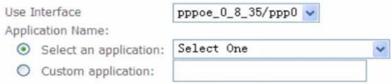
text_image
Use Interface Application Name: Select an application: Custom application: pppoe_0_8_35/ppp0 Select One| Save/Apply |
| Trigger Port Start | Trigger Port End | Trigger Protocol | Open Port Start | Open Port End | Open Protocol | ||||||
| TCP | √ | TCP | √ | ||||||||
| TCP | √ | TCP | √ | ||||||||
| TCP | √ | TCP | √ | ||||||||
| TCP | √ | TCP | √ | ||||||||
| TCP | √ | TCP | √ | ||||||||
| TCP | √ | TCP | √ | ||||||||
| TCP | × | TCP | √ | ||||||||
| TCP | √ | TCP | √ | ||||||||
| TCP | √ | TCP | √ | ||||||||
| Save/Apply |
Use Interface: select from the drop-down menu the interface you want rule applies to.
Application Name:
① Select an application: select an existing application from the drop-down menu.
① Custom application: creating your own service.
Trigger Port Start: type a number used as trigger port start number. Trigger dynamically opens up the 'Open Ports' in the firewall when an application on the LAN initiates a TCP/UDP connection to a remote party using the 'Triggering Ports'.
Trigger Port End: type a number used as trigger port end number.
Triggering Protocol: select the trigger protocol.
Open Port Start: type a number used as open port start number. Open ports used for remote application in WAN side to communication with one in LAN side.
Open Port End: type a number used as open port end number.
Open Protocol: select the open protocol.
If users in LAN want to set a Aim Talk with someone in the WAN side, he want the router to open dynamically a port(eg:5191) for the user to connect back to build the talk when he initiate a TCP/UDP connection with the triggering port (eg:4099), then he can set as follows.
Set up
Select the Aim Talk application, or you can create yourself. Set the Trigger and Open port.
NAT -- Port Triggering
Some applications such as games, video conferencing, remote access applications and others require that specific ports in the Router's firewall be opened for access by the applications. You can configure the port settings from this screen by selecting an existing application or creating your own (Custom application) and click "Save/Apply" to add it.
Remaining number of entries that can be configured:32
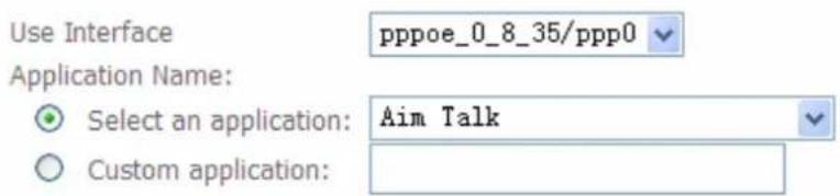
text_image
Use Interface pppoe_0_8_35/ppp0 Application Name: Select an application: Aim Talk Custom application:
| Trigger Port Start | Trigger Port End | Trigger Protocol | Open Port Start | Open Port End | Open Protocol | ||||||
| 4099 | 4099 | TCP | ✓ | 5191 | 5191 | TCP | ✓ | ||||
| TCP | ✓ | TCP | ✓ | ||||||||
| TCP | ✓ | TCP | ✓ | ||||||||
| TCP | ✓ | TCP | ✓ | ||||||||
| TCP | ✓ | TCP | ✓ | ||||||||
| TCP | ✓ | TCP | ✓ | ||||||||
| TCP | ✓ | TCP | ✓ | ||||||||
| TCP | ✓ | TCP | ✓ | ||||||||

2. Press Save/Apply to summit your settings.
NAT -- Port Triggering Setup
Some applications require that specific ports in the Router's firewall be opened for access by the remote parties. Port Trigger dynamically opens up the 'Open Ports' in the firewall when an application on the LAN initiates a TCP/UDP connection to a remote party using the 'Triggering Ports'. The Router allows the remote party from the WAN side to establish new connections back to the application on the LAN side using the 'Open Ports'. A maximum 32 entries can be configured.

| Application Name | Trigger | Open | WAN Interface | Remove | ||||
| Protocol | Port Range | Protocol | Port Range | |||||
| Start | End | Start | End | |||||
| Aim Talk | TCP | 4099 | 4099 | TCP | 5191 | 5191 | ppp0 | |
If you want to delete the rule, please check the Remove checkbox first then press Remove button.
DMZ Host
The DMZ Host is a local computer exposed to the Internet. When setting a particular internal IP address as the DMZ Host, all incoming packets will be checked by the Firewall and NAT algorithms then passed to the DMZ host, when a packet received does not use a port number used by any other Virtual Server entries.
NAT -- DMZ Host
The Broadband Router will forward IP packets from the WAN that do not belong to any of the applications configured in the Virtual Servers table to the DMZ host computer.
Enter the computer's IP address and click 'Apply' to activate the DMZ host.
Clear the IP address field and click 'Apply' to deactivate the DMZ host.
DMZ Host IP Address:
Save/Apply
DMZ Host IP Address: Enter the IP Address of a host you want it to be a DMZ host.

Using port mapping does have security implications, since outside users are able to connect to PCs on your network. For this reason you are advised to use specific Virtual Server entries just for the ports your application requires instead of simply using DMZ or creating a Virtual Server entry for "All" protocols, as doing so results in all connection attempts to your public IP address accessing the specified PC.

Attention
If you have disabled the NAT option in the WAN-ISP section, the Virtual Server function will hence be invalid.
If the DHCP server option is enabled, you have to be very careful in assigning the IP addresses of the virtual servers in order to avoid conflicts. The easiest way of configuring Virtual Servers is to manually assign static IP address to each virtual server PC, with an address that does not fall into the range of IP addresses that are to be issued by the DHCP server. You can configure the virtual server IP address manually, but it must still be in the same subnet as the router.
Security
IP Filtering
IP filtering enables you to configure your router to block specified internal/external users (IP address) from Internet access, or you can disable specific service requests (Port number) to /from Internet. The relationship among all filters is “or” operation, which means that the router checks these different filter rules one by one, starting from the first rule. As long as one of the rules is satisfied, the specified action will be taken.
i Outgoing
Outgoing IP Filtering Setup
By default, all outgoing IP traffic from LAN is allowed, but some IP traffic can be BLOCKED by setting up filters.
Choose Add or Remove to configure outgoing IP filters.
change default policy
| Filter Name | IP Version | Protocol | SrcIP/ PrefixLength | SrcPort | DstIP/ PrefixLength | DstPort | Remove |
Add
Remove
In this outgoing IP filter, by default, all outgoing traffic from LAN is allowed, but some IP traffic can be Blocked by setting up rules.
If you want all the outgoing traffic from LAN to be blocked by default, only the rules set below can be allowed, then please press change the default policy.
Click Add to add new rules.
Add IP Filter -- Outgoing
The screen allows you to create a filter rule to identify outgoing IP traffic by specifying a new filter name and at least one condition below. All of the specified conditions in this filter rule must be satisfied for the rule to take effect. Click 'Apply/Save' to save and activate the filter.
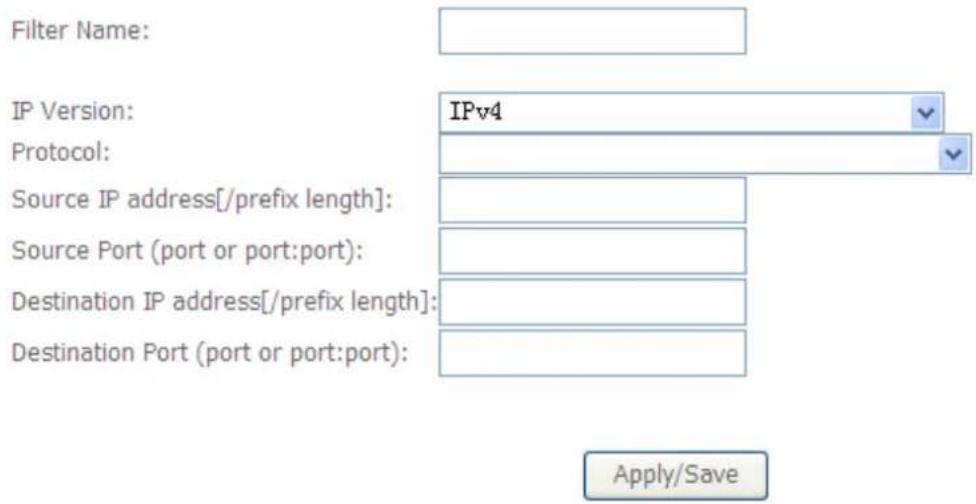
text_image
Filter Name: IP Version: IPv4 Protocol: Source IP address[/prefix length]: Source Port (port or port:port): Destination IP address[/prefix length]: Destination Port (port or port:port): Apply/SaveFilter name: a user-defined filter name or you can select from the drop-down menu the application, and leave the automatically generated name as the Filter name.
IP Version: IP Version, here IPv4.
Protocol: Specify the packet type (TCP/UDP, TCP, UDP, ICMP) that the rule applies to.
Source IP Address / Destination IP Address: This is the Address-Filter used to allow or block traffic to/from particular IP address (es). Input the IP or IP/prefix (such as single IP: 192.168.1.135/32. Subnet: 192.168.1.128/30) you want to filter out. If you leave empty, it means any IP address.
Source Port: This Port defines the ports allowed to be used by the Remote/WAN to connect to the application. Default is set from range 1 \~ 65535. It is recommended that this option be configured by an advanced user.
Destination Port: This is the Port that defines the application. Default is set from range 1 \~ 65535.
For example, if there is an outgoing rule set as follows, then the 80 application between source IP and destination IP will be blocked.
Outgoing IP Filtering Setup
By default, all outgoing IP traffic from LAN is allowed, but some IP traffic can be BLOCKED by setting up filters.
Choose Add or Remove to configure outgoing IP filters.
change default policy
| Filter Name | IP Version | Protocol | SrcIP/ PrefixLength | SrcPort | DstIP/ PrefixLength | DstPort | Remove |
| Web | 4 | TCP or UDP | 192.168.1.1 | 80 | 168.100.1.1 | 80 |
① Incomig
Incoming IP Filtering Setup
When the firewall is enabled on a WAN or LAN interface, all incoming IP traffic is blocked. However, some IP traffic can be ACCEPTED by setting up filters.
Choose Add or Remove to configure incoming IP filters.
change default policy
| Filter Name | Interfaces | IP Version | Protocol | SrcIP/ PrefixLength | SrcPort | DstIP/ PrefixLength | DstPort | Remove |
Add Remove
In this Incoming IP filter, all incoming IP traffic is blocked when firewall is enabled on a WAN or LAN interface. But you can set up some rules to allow some IP traffic go through.
You can change the default policy to change the default IP incoming policy.
Click Add to add the new rules.
Add IP Filter -- Incoming
The screen allows you to create a filter rule to identify incoming IP traffic by specifying a new filter name and at least one condition below. All of the specified conditions in this filter rule must be satisfied for the rule to take effect. Click 'Apply/Save' to save and activate the filter.
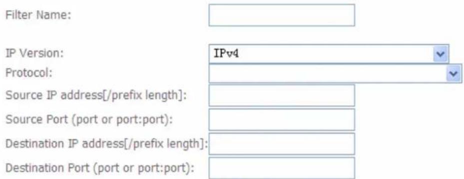
text_image
Filter Name: IP Version: IPv4 Protocol: Source IP address[/prefix length]: Source Port (port or port:port): Destination IP address[/prefix length]: Destination Port (port or port:port):WAN Interfaces (Configured in Routing mode and with firewall enabled) and LAN Interfaces Select one or more WAN/LAN interfaces displayed below to apply this rule.
Select All
pppoe_0_8_35/ppp0.1
br0/br0
Apply/Save
Filter name: a user-defined filter name or you can select from the drop-down menu the application, and leave the automatically generated name as the Filter name.
IP Version: IP Version, here IPv4.
Protocol: Specify the packet type (TCP/UDP, TCP, UDP, ICMP) that the rule applies to.
Source IP Address / Destination IP Address: This is the Address-Filter used to allow or block traffic to/from particular IP address (es). Input the IP or IP/prefix ((such as single IP: 192.168.1.135/32. Subnet: 192.168.1.128/30) you want to filter out. If you leave empty, it means any IP address.
Source Port: This Port defines the ports allowed to be used by the Remote/WAN to connect to the application. Default is set from range 1 \~ 65535. It is recommended that this option be configured by an advanced user.
Desitination Port: This is the Port that defines the application. Default is set from range 1 \~ 65535.
WAN Interface and LAN Interface: select one or more WAN/LAN interface displayed below to apply this rule. Note: only the WAN interfaces in Routing mode and with firewall enabled will be displayed.
MAC Filtering
MAC Filtering is only effective on ATM PVCs configured in Bridge mode.
FORWARDED means that all MAC layer frames will be forwarded except those matching with any of the specified rules in the following table.
BLOCKED means that all MAC layer frames will be blocked except those matching with any of the specified rules in the following table.
| Interface | Policy | Change |
| atm0.2 | FORWARD |

Choose Add or Remove to configure MAC filtering rules.
| Interface | Protocol | Destination MAC | Source MAC | Frame Direction | Remove |

By default, all MAC frames of the interface in Bridge Mode will be forwarded, you can check Change checkbox and then press Change Policy to change the settings to the interface.
For example, from above, the interface atm0.2 is of bridge mode, and all the MAC layer frames will be forwarded, but you can set some rules to let someone matched the rules to blocked.
Click Add to add rules.
Add MAC Filter
Create a filter to identify the MAC layer frames by specifying at least one condition below. If multiple conditions are specified, all of them take effect. Click "Apply" to save and activate the filter.
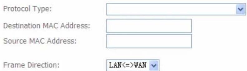
text_image
Protocol Type: Destination MAC Address: Source MAC Address: Frame Direction: LAN<=WANWAN Interfaces (Configured in Bridge mode only)


Protocol type: select from the drop-down menu the protocol that applies to this rule.
Destination /Source MAC Address: enter the destination/source address.
Frame Direction: select the frame direction this rule applies, both LAN and WAN: LAN <=>WAN, only LAN to WAN: LAN=>WAN, only WAN to LAN: WAN=>LAN.
WAN Interfaces: select the interfaces configured in Bridge mode.
Parental Control
Time Restriction
A MAC (Media Access Control) address is the unique network hardware identifier for each PC on your network's interface (i.e. its Network Interface Card or Ethernet card). Using your router's MAC Address Filter function, you can configure the network to block specific machines from accessing your LAN during the specified time.
This page adds time of day restriction to a special LAN device connected to the Router. The 'Browser's MAC Address' automatically displays the MAC address of the LAN device where the browser is running. To restrict other LAN device, click the "Other MAC Address" button and enter the MAC address of the other LAN device. To find out the MAC address of a Windows based PC, go to command window and type "ipconfig /all".
Access Time Restriction -- A maximum 16 entries can be configured.

text_image
Username MAC Mon Tue Wed Thu Fri Sat Sun Start Stop Remove Add RemoveClick Add to add the rules.
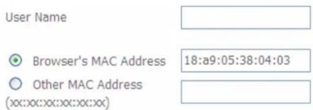
text_image
User Name Browser's MAC Address 18:a9:05:38:04:03 Other MAC Address (xx:xx:xx:xx:xx:xx)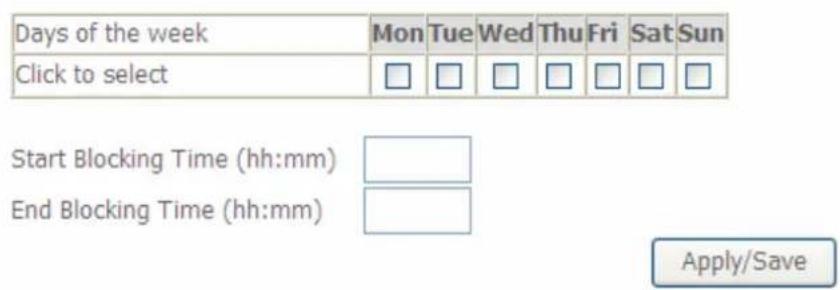
text_image
Days of the week Mon Tue Wed Thu Fri Sat Sun Click to select Start Blocking Time (hh:mm) End Blocking Time (hh:mm) Apply/SaveUsername: user-defined name.
Browser's MAC address: display the address of the device where the browser is running.
Other MAC Address: enter the MAC address(es) you want to block to access the router and LAN. The format of MAC address could be: xx:xx:xx:xx:xx:xx.
Days of the week: select the days of a week this rule takes efforts.
Start Time: enter the start time of each day in hh:mm format. Leaving it empty means 00:00.
End Time: enter the end time of each day in hh:mm format. Leaving it empty means 23:59.
Click Apply/Save to confirm your settings. The following prompt window will appear to remind you of the attention.

text_image
Message from webpage WARNING: Modem time is not set and Parental Control will not work correctly without it! Please set it in 'Management/Internet Time' OKAccess Time Restriction -- A maximum 16 entries can be configured.
| Username | MAC | Mon | Tue | Wed | Thu | Fri | Sat | Sun | Start | Stop | Remove |
| 12 | 18:a9:05:38:04:12 | x | x | 0:0 | 23:59 |
Here you can see that the user 12 with a MAC 18:a9:05:04:12 is blocked to access the router from 00:00 to 23:59 Monday through Tuesday.
If you needn't this rule, you can check the box, press Remove, it will be OK.
Url Filter
URL (Uniform Resource Locator – e.g. an address in the form of http://www.abcde.com or http://www.example.com) filter rules allow you to prevent users on your network from accessing particular websites by their URL. There are no pre-defined URL filter rules; you can add filter rules to meet your requirements.
URL Filter -- Please select the list type first then configure the list entries. Maximum 100 entries can be configured.
Exclude -- Deny computers to access the following web sites in the list.
Include -- Allow computers to access only the following sites in the list.
URL List Type: ○ Exclude ○ Include
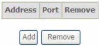
text_image
Address Port Remove Add RemoveURL List Type:
Exclude: Deny computers to access the following web sites in the list.
i Include: Allow computers to access the following web sites in the list.
If you only want computers to access some specific web sites. Select Include (for example), then press Add.
Parental Control -- URL Filter Add
Enter the URL address and port number then click "Apply/Save" to add the entry to the URL filter.
URL Address:
Port Number:
(Default 80 will be applied if leave blank.)
Apply/Save
URL Address: enter the URL address.
Port Number: type the port number, if you leave it empty, then Default is 80.
For example, http://www.qq.com.
URL List Type: ○ Exclude ● Include
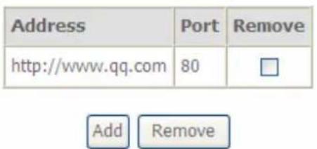
text_image
Address Port Remove http://www.qq.com 80 □ Add RemoveThen you only allow computers to access www.qq.com.
And then if you want computers to access any other websites except http://www.qq.com, you only need to press Exclude radio button.
In a word, press the Include radio button, you can Allow computers to access the following web sites in the list.
While press the Exclude radio button, you can Deny computers to access the following web sites in the list.
You can first add some websites in the list, then you can change the accessing property for these websites via pressing Include or Exclude radio button.
But when the list is empty (no rule exists), either you press Include or Exclude radio button, you will have the same condition, thus allowing computers to accessing all websites without any restriction.
QoS - Quality of Service
QoS helps you to control the data upload traffic of each application from LAN (Ethernet) to WAN (Internet). It facilitates you the features to control the quality and speed of throughput for each application when the system is running with full upstream load.
QoS -- Queue Management Configuration
If Enable QoS checkbox is selected, choose a default DSCP mark to automatically mark incoming traffic without reference to a particular classifier. Click 'Apply/Save' button to save it.
Note: If Enable Qos checkbox is not selected, all QoS will be disabled for all interfaces.
Note: The default DSCP mark is used to mark all egress packets that do not match any classification rules.
Enable QoS
Select Default DSCP Mark default (000000)
Apply/Save
Enable QoS: Check to activate this function and the following field will be available.
If Enable QoS checkbox is selected, choose a default DSCP mark to automatically mark incoming traffic without reference to a particular classifier.
If Enable Qos checkbox is not selected, all QoS will be disabled for all interfaces.
Select Default DSCP Mark: Select the default DSCP mark from the list-box. Differentiated Services Code Point (DSCP) is the first 6 bits in the ToS byte. DSCP Mark allows users to classify the traffic of the application to be executed according to the DSCP value. The default DSCP mark is used to mark all egress packets that do not match any classification rules.
Note: Before configuring Queue config and QoS Classification section, you must enable QoS function, for the reason that the queues' activation will depend on this, the classification will also depend on this.
The corresponding IP precedence and DSCP mapping table is listed below.
IP Precedence and DSCP Mapping Table
| Mapping Table | |
| Default (000000) | Best Effort |
| EF(101110) | Expedited Forwarding |
| AF11 (001010) | Assured Forwarding Class1(L) |
| AF12 (001100) | Assured Forwarding Class1(M) |
| AF13 (001110) | Assured Forwarding Class1(H) |
| AF21 (010010) | Assured Forwarding Class1(L) |
| AF22 (010100) | Assured Forwarding Class1(M) |
| AF23 (010110) | Assured Forwarding Class1(H) |
| AF31 (011010) | Assured Forwarding Class1(L) |
| AF32 (011100) | Assured Forwarding Class1(M) |
| AF33 (011110) | Assured Forwarding Class1(H) |
| AF41 (100010) | Assured Forwarding Class1(L) |
| AF42 (100100) | Assured Forwarding Class1(M) |
| AF43 (100110) | Assured Forwarding Class1(H) |
| CS1(001000) | Class Selector(IP precedence)1 |
| CS2(010000) | Class Selector(IP precedence) 2 |
| CS3(011000) | Class Selector(IP precedence)3 |
| CS4(100000) | Class Selector(IP precedence) 4 |
| CS5(101000) | Class Selector(IP precedence) 5 |
| CS6(110000) | Class Selector(IP precedence) 6 |
| CS7(111000) | Class Selector(IP precedence) 7 |
DSCP indicates three kinds of service, Class Selector (CS), Assured Forwarding (AF) and Expedited Forwarding (EF). AF1, AF2, AF3 and AF4 are four kinds of assured forwarding services. Each AF has three different packet loss priorities from high, medium, to low. Also, CS1-CS7 indicates the IP precedence.
Click Apply to confirm the settings.
Queue Config
Queue is a technology of managing congestion providing precautions with the packets storing and scheduling. Queue Config allows you to configure a QoS queue entry and assign it to a specific network interface. Each queue entry set here will be used by the classifier to place ingress packets appropriately.
QoS Queue Setup
In ATM mode, maximum 16 queues can be configured.
In PTM mode, maximum 8 queues can be configured.
For each Ethernet interface, maximum 4 queues can be configured.
| Name | Key | Interface | Scheduler Alg | Precedence | Weight | DSL Latency | PTM Priority | Enable | Remove |
| Default Queue | 38 | atm0 | SP | 8 | Path0 | ||||
| Default Queue | 39 | atm1 | SP | 8 | Path0 |

Note: the interface set in the LAN2 Interface> ATM Interface will be list as Default Queue here, and the parameters listed above can be configured there. For detail, please turn to LAN2 Interface> ATM Interface section for help. You can also add other queues to the ATM interfaces despite of the default queue.
Name: the queue name.
Key: the item number.
Interface: the queue interface.
Scheduler Algorithm: the QoS Scheduler Algorithm, SP(Strict Priority) or WFQ(Weight Fair Queuing)
Precedence: the priority identification.
Weight: the weight value, 1-63. the highest is 63.
PTM Priority: the PTM priority, normal or high.
Enable: check the enable check-box, then press Enable to activate the queue. If you want to disable this queue, you can uncheck the corresponding check-box and press Enable, the queue will be disabled.
If the queue is enabled, you will see a tick, like ☑. Otherwise, the queue is disabled.
Click Add to create a queue.
QoS Queue Configuration
This screen allows you to configure a QoS queue and assign it to a specific layer2 interface. The scheduler algorithm is defined by the layer2 interface.
Note: For SP scheduling, queues assigned to the same layer2 interface shall have unique precedence. Lower precedence value implies higher priority for this queue relative to others
Click 'Apply/Save' to save and activate the queue.
Name:

Enable:
Interface:
Apply/Save
Name: Type the name of the queue.
Enable: Select whether to enable the queue.
Interface: Select which interface this queue applies to.
Select interface, the following corresponding parameters will appear to let you configure, Enter the information, Click Apply to conform. Then the item will be listed in the table.
QoS Queue Configuration
This screen allows you to configure a QoS queue and assign it to a specific layer2 interface. The scheduler algorithm is defined by the layer2 interface.
Note: For SP scheduling, queues assigned to the same layer2 interface shall have unique precedence. Lower precedence value implies higher priority for this queue relative to others
Click 'Apply/Save' to save and activate the queue.
Name:
eth0
Enable:
Enable
Interface:
eth0
Precedence:

Apply/Save
Precedence: the precedence of the queue, interface eth0-eth3, 4 levels from high to low are 1-4. ATM interfaces, 7 levels from high to low are 1-7, for the precedence of the default queue with the interface of SP Scheduler Algorithm is 8. Here if the interface is of WFQ Scheduler Algorithm, you should enter the weight of the queue.
Click Apply/Save to save and the added queue will be listed as below.
QoS Queue Setup
In ATM mode, maximum 16 queues can be configured.
In PTM mode, maximum 8 queues can be configured.
For each Ethernet interface, maximum 4 queues can be configured.
| Name | Key | Interface | Scheduler Alg | Precedence | Weight | DSL Latency | PTM Priority | Enable | Remove |
| Default Queue | 38 | atm0 | SP | 8 | Path0 | ☑ | |||
| Default Queue | 39 | atm1 | SP | 8 | Path0 | ☑ | |||
| eth0 | 40 | eth0 | SP | 1 | ☑ | ☐ |
Add Enable Remove
Enable: check the enable check-box, then press Enable to activate the queue. If you want to disable this queue, you can uncheck the corresponding check-box and press Enable, the queue will be disabled.
Remove: To delete the QoS rule from the table, check Remove checkbox then click Remove button to delete the selected item.
Note: only the queue added via the above mode can be directly removed here, the default queue can't be removed here, if you want to remove them, remove the interface in LAN2 Interface> ATM Interface section.
Note: In ATM mode, maximum queues can be configured: 16
For each Ethernet interface, maximum queues can be configured: 4.
QoS Classification
This screen displays a packet QoS summary table and allows user to add or remove a QoS classification class. This is the main place to configure the classification, marking and queuing rules.
QoS Classification Setup -- A maximum 32 entries can be configured.
Choose Add or Remove to configure network traffic classes.
| CLASSIFICATION CRITERIA | CLASSIFICATION RESULTS | |||||||||||||||||||
| Class Name | Order | Class Intf | Ether Type | SrcMAC/ Mask | DstMAC/ Mask | SrcIP/ PrefixLength | DstIP/ PrefixLength | Proto | SrcPort | DstPort | DSCP Check | 802.1P Check | Queue Key | DSCP Mark | 802.1P Mark | VlanID Tag | Rate Control (kbps) | Enable | Remove | |
Add Enable Remove
Click Add to add Network Traffic Class Rule.
Add Network Traffic Class Rule
The screen creates a traffic class rule to classify the upstream traffic, assign queue which defines the precedence and the interface and optionally overwrite the IP header DSCP byte. A rule consists of a class name and at least one condition below. All of the specified conditions in this classification rule must be satisfied for the rule to take effect. Click 'Apply/Save' to save and activate the rule.
Traffic Class Name:
Rule Order:
Rule Status:
text_image
Last DisableSpecify Classification Criteria
A blank criterion indicates it is not used for classification.
Class Interface:
Ether Type:
Source MAC Address:
Source MAC Mask:
Destination MAC Address:
Destination MAC Mask:
text_image
LANSpecify Classification Results
Must select a classification queue. A blank mark or tag value means no change.
Assign Classification Queue:
Mark Differentiated Service Code Point (DSCP):
Mark 802.1p priority:
Tag VLAN ID [0-4094]:
text_image
Screenshot of a software interface with three horizontal bars and two checkmarks, likely for input validation or editing.Apply/Save
The classification rule is a 'AND' mode, that is a rule takes effect only when all of the specified conditions must be satisfied.
Parameters
Traffic Class Name: Assign a name for this class to uniquely identify the others among multiple classes.
Rule Order: Select the priority for this class rule.
Rule Status: Select Enable to activate this class rule.
Specify Classification Criteria
The following parameters are to be classification rule. Enter or select appropriate parameters on the following fields. A blank criterion indicates it is not used for classification.
Class Interface: select the interface you want to be the one aspect of the classification criteria. Here "LAN" and "WAN" can be viewed as IP QoS, the others can be viewed as ported-based QoS, which means that control the QoS of certain port such. For example, if you select eth0 port, then criteria applies to this port, that is ported-based QoS.
Entry Type: select the application type.
Source/destination MAC Address: enter the source and destination MAC address as the QoS Classification Criteria. The format should be xx:xx:xx:xx:xx:xx.
Source/destination MAC Mask: MAC mask is similar to IP mask, and the format also should be xx:xx:xx:xx:xx:xx. It is used to hide some information of the MAC address. '1', means needed and '0' means ignored. For example, MAC address e0:3b:4a:c2:ca:e2 and MAC mask ff:ff:ff:00:00:00, that is whatever MAC address while matches e0:3b:4a:XX:XX:XX, will be accepted.
Specify Classification Results
Enter or select appropriate parameters you want for the packets matched the above classification criteria in the following fields. You have to choose a classification queue. A blank mark or tag value means no change.
Assign Classification Queue: assign classification queue from the drop-down box. If you want to select the queue, you should make sure the specific queue is enabled in Queue Config section.
Mark Differentiated Service Code Point (DSCP): select the DSCP you want to be the new DSCP for the packets which matched the above classification criteria.
Mark 802.1p priority: it is a LAN Layer 2 QoS/CoS Protocol for Traffic Prioritization. It is interoperable with IEEE 802.1Q. 802.1p has 8 kinds of priority.
Tag VLAN ID: enter the tag VLAN ID, 0-4094, used to determine the VLAN the frame belongs to.
Note: 802.1p/vlan tag feature be supported only when in bridge mode, DSL WAN interface.
Click Apply/Save to confirm the settings and you will be returned to the QoS Classification page.
Enable: To disable the item, please uncheck Enable check box then click Enable button.
Remove: To delete the QoS class from the table, check Remove checkbox then click Remove button to delete the selected item.
Set up a QoS Classification
IP QoS
LAN to WAN IP QoS
- It is a QoS controlling the traffic from LAN to WAN. So first make sure there is at least one WAN queue. If you have configured WAN interface and it will appear as a default queue, you can also add other queues of the specific interface. See Queue Config.
Here we have a atm0 (WAN interface), the interface has a default queue and an added queue. Make sure to enable the queue.
QoS Queue Setup
In ATM mode, maximum 16 queues can be configured.
In PTM mode, maximum 8 queues can be configured.
For each Ethernet interface, maximum 4 queues can be configured.
| Name | Key | Interface | Scheduler Alg | Precedence | Weight | DSL Latency | PTM Priority | Enable | Remove |
| Default Queue | 38 | atm0 | SP | 8 | Path0 | ☑ | |||
| Default Queue | 39 | atm1 | SP | 8 | Path0 | ☑ | |||
| eth0 | 40 | eth0 | SP | 1 | ☑ | ☐ | |||
| atm01 | 42 | atm0 | SP | 2 | Path0 | ☑ | ☐ |

- In QoS Classification Setup page, Click Add to add a Qos Classification.
QoS Classification Setup -- A maximum 32 entries can be configured.
Choose Add or Remove to configure network traffic classes.
| CLASSIFICATION CRITERIA | CLASSIFICATION RESULTS | ||||||||||||||||||
| Class Name | Order | Class Intf | Ether Type | SrcMAC/ Mask | DstMAC/ Mask | SrcIP/ PrefixLength | DstIP/ PrefixLength | Proto | SrcPort | DstPort | DSCP Check | 802.1P Check | Queue Key | DSCP Mark | 802.1P Mark | VlanID Tag | Rate Control (kbps) | Enable | Remove |

Then in the appeared Add Network Traffic Class Rule page, enter the information to set up a rule.
1) Specify the rule name, rule order, and rule status.
Traffic Class Name:
Rule Order:
Rule Status:
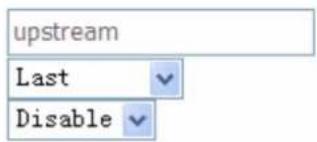
text_image
upstream Last Disable2) Specify the classification criteria. Here you can set every parameter to strictly control the specific traffic or you can set several parameters to let them be the key elements to control the traffic. A blank criterion indicates it is not used for classification.
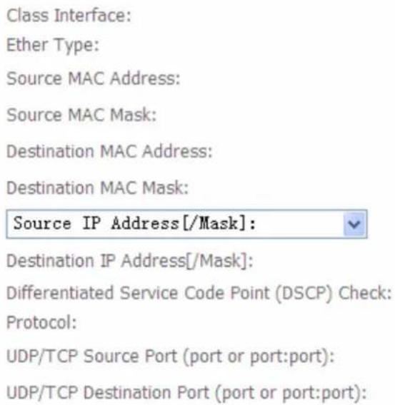
text_image
Class Interface: Ether Type: Source MAC Address: Source MAC Mask: Destination MAC Address: Destination MAC Mask: Source IP Address[/Mask]: Destination IP Address[/Mask]: Differentiated Service Code Point (DSCP) Check: Protocol: UDP/TCP Source Port (port or port:port): UDP/TCP Destination Port (port or port:port):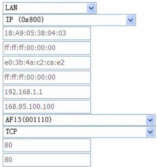
text_image
LAN IP (0x800) 18:A9:05:38:04:03 ff:ff:ff:00:00:00 e0:3b:4a:c2:ca:e2 ff:ff:ff:00:00:00 192.168.1.1 168.95.100.100 AF13(001110) TCP 80 803) Specify the classification results. Here you must Assign Classification Queue. Whether the following parameters are needed is according to your needs. If you do not want to change the original information, please leave it empty. The queues listed here in the Assign Classification Queue are WAN interface queues set in Queue Config section. Select the needed queue. If you find none queues here, turn back to check whether you have configured a queue and enable it.
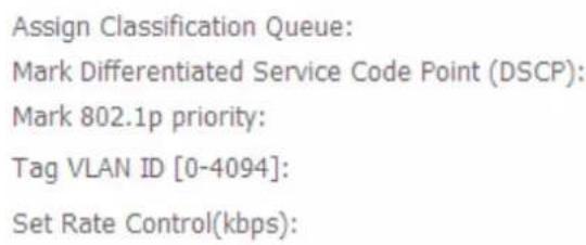
text_image
Assign Classification Queue: Mark Differentiated Service Code Point (DSCP): Mark 802.1p priority: Tag VLAN ID [0-4094]: Set Rate Control(kbps):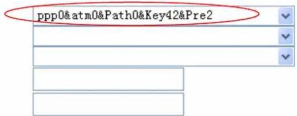
text_image
ppp0&atm0&Path0&Key42&Pre2- Click Apply/Save to save your settings. The added rule will listed as below.
| CLASSIFICATION CRITERIA | CLASSIFICATION RESULTS | |||||||||||||||||||
| Class Name | Order | Class Intf | Ether Type | SrcMAC/ Mask | DstMAC/ Mask | SrcIP/ Prefix length | DstIP/ Prefix length | Proto | SrcPort | DstPort | DSCP Check | 802.1P Check | Queue Key | DSCP Mark | 802.1P Mark | VlanID Tag | Rate Control (kbps) | Enable | Remove | |
| upstream | 1 | LAN | IP | 18:A9:05:38:04:03/ff:ff:ff:00:00:00 | e0:3b:4a:c2:ca:e2/ff:ff:ff:00:00:00 | 192.168.1.1 | 168.95.100.100 | TCP | 80 | 80 | AF13 | 38 | ☐ | ☐ | ||||||

Enable: check the enable check-box, then press Enable to activate the rule. If you want to disable this rule, you can uncheck the corresponding check-box and press Enable button, the rule will be disabled.
Remove: To delete the QoS class from the table, check Remove checkbox then click Remove button to delete the selected item.
WAN to LAN IP QoS
- Here we take WAN to LAN (P1) QoS for example. Make sure there are enabled port P1 based queues here. LAN queues need your configuration. You can enable wireless to enable WMM queues by default or add P1-P4 ported based queues manually.
| eth0 | 40 | eth0 | SP | 1 |
- In QoS Classification Setup page, Click Add to add a QoS Classification.
| CLASSIFICATION CRITERIA | CLASSIFICATION RESULTS | |||||||||||||||||||
| Class Name | Order | Class Intl | Ether Type | SrcMAC/ Mask | DstMAC/ Mask | SrcIP/ PrefixLength | DstIP/ PrefixLength | Proto | SrcPort | DstPort | DSCP Check | 802.1P Check | Queue Key | DSCP Mark | 802.1P Mark | VlanID Tag | Rate Control (kbps) | Enable | Remove | |
| upstream | 1 | LAN | IP | 18:A9:05:38:04:03/ff:ff:ff:00:00:00 | e0:3b:4a:c2:ca:e2/ff:ff:ff:00:00:00 | 192.168.1.1 | 168.95.100.100 | TCP | 80 | 80 | AF13 | 38 | ☐ | ☐ | ||||||

Then in the Add Network Traffic Class Rule page, enter the information to set up a rule.
Traffic Class Name:
Rule Order:
Rule Status:
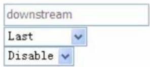
Specify Classification Criteria
A blank criterion indicates it is not used for classification.
Class Interface:
Ether Type:
Source MAC Address:
Source IP Address [/Mask]:
Destination IP Address[/Mask]:
Differentiated Service Code Point (DSCP) Check:
Protocol:
UDP/TCP Source Port (port or port:port):
UDP/TCP Destination Port (port or port:port):
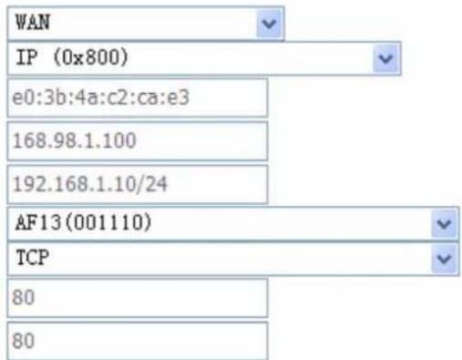
text_image
WAN IP (0x800) e0:3b:4a:c2:ca:e3 168.98.1.100 192.168.1.10/24 AF13(001110) TCP 80 80Specify Classification Results
Must select a classification queue. A blank mark or tag value means no change.
Assign Classification Queue:
Mark Differentiated Service Code Point (DSCP):

text_image
eth0&Key40&Pre1
- Click Apply to save your settings. The added rule will be listed as below.
| CLASSIFICATION CRITERIA | CLASSIFICATION RESULTS | ||||||||||||||||||
| Class Name | Order | Class Intf | Ether Type | SrcMAC/ Mask | DstMAC/ Mask | SrcIP/ PrefixLength | DstIP/ PrefixLength | Proto | SrcPort | DstPort | DSCP Check | 802.1P Check | Queue Key | DSCP Mark | 802.1P Mark | VlanID Tag | Rate Control (kbps) | Enable | Remove |
| upstream | 1 | LAN | JP | 18:A9:05:38:04:03/ff:ff:ff:00:00:00 | e0:3b:4a:c2:cae2/ff:ff:ff:00:00:00 | 192.168.1.1 | 168.95.100.100 | TCP | 80 | 80 | AF13 | 38 | |||||||
| downstream | 2 | WAN | JP | e0:3b:4a:c2:cae3 | 168.98.1.100 | 192.168.1.10/24 | TCP | 80 | 80 | AF13 | 40 | ||||||||
Add Enable Remove
Port-based QoS
Take port eth0 to WAN QoS for example.
- First make sure there is at least a WAN queue and it is enabled.
| Name | Key | Interface | Scheduler Alg | Precedence | Weight | DSL Latency | PTM Priority | Enable | Remove |
| Default Queue | 38 | atm0 | SP | 8 | Path0 | ☑ | |||
| Default Queue | 39 | atm1 | SP | 8 | Path0 | ☑ | |||
| eth0 | 40 | eth0 | SP | 1 | ☑ | ☐ | |||
| atm01 | 42 | atm0 | SP | 2 | Path0 | ☑ | ☐ |
- In QoS Classification Setup page, Click Add to add a QoS Classification.
QoS Classification Setup -- A maximum 32 entries can be configured.
Choose Add or Remove to configure network traffic classes.
| CLASSIFICATION CRITERIA | CLASSIFICATION RESULTS | ||||||||||||||||||
| Class Name | Order | Class Intf | Ether Type | SrcMAC/ Mask | DstMAC/ Mask | SrcIP/ PrefixLength | DstIP/ PrefixLength | Proto | SrcPort | DstPort | DSCP Check | 802.1P Check | Queue Key | DSCP Mark | 802.1P Mark | VlanID Tag | Rate Control (kbps) | Enable | Ren |
| upstream | 1 | LAN | IP | 18:A9:05:38:04:03/ff:ff:ff:00:00:00 | e0:2b:4a:c2:ca:e2/ff:ff:ff:00:00:00 | 192.168.1.1 | 168.95.100.100 | TCP | 80 | 80 | AF13 | 38 | ☐ | [ | |||||
| downstream | 2 | WAN | IP | e0:3b:4a:c2:cc:e3 | 168.98.1.100 | 192.168.1.10/24 | TCP | 80 | 60 | AF13 | 40 | ☐ | [ | ||||||

Then in the Add Network Traffic Class Rule page, enter the information to set up a rule to your needs. To Assign Classification queue, select the needed WAN queue.
Traffic Class Name:
Rule Order:
Rule Status:
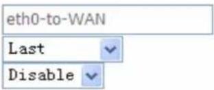
text_image
eth0-to-WAN Last DisableSpecify Classification Criteria
A blank criterion indicates it is not used for classification.
Class Interface:
Ether Type:
Source MAC Address:
Source MAC Mask:
Destination MAC Address:
Destination MAC Mask:
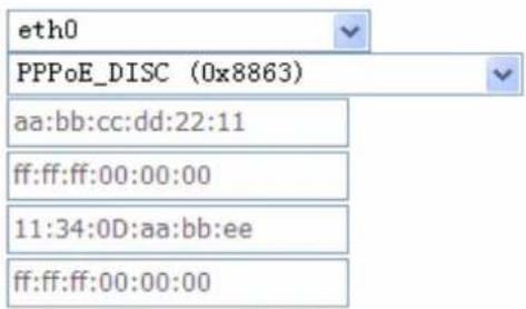
text_image
eth0 PPPoE_DISC (0x8863) aa:bb:cc:dd:22:11 ff:ff:ff:00:00:00 11:34:0D:aa:bb:ee ff:ff:ff:00:00:00Specify Classification Results
Must select a classification queue. A blank mark or tag value means no change.
Assign Classification Queue:
Mark Differentiated Service Code Point (DSCP):
Mark 802.1p priority:
Tag VLAN ID [0-4094]:
Set Rate Control(kbps):
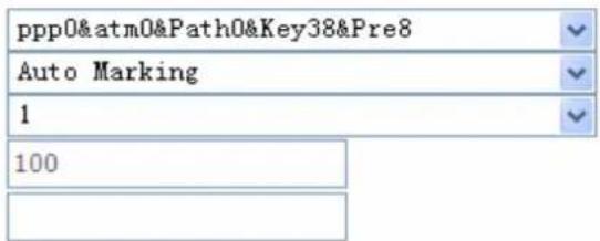
text_image
ppp0@atm0&Path0&Key38&Pre8 Auto Marking 1 100Apply/Save
3. Click Apply to save your settings and the added rule will be listed as below.
QoS Classification Setup -- A maximum 32 entries can be configured.
Choose Add or Remove to configure network traffic classes.
| CLASSIFICATION CRITERIA | CLASSIFICATION RESULTS | ||||||||||||||||||
| Class Name | Order | Class Intl | Ether Type | SrcMAC/ Mask | DstMAC/ Mask | SrcIP/ PrefixLength | DstIP/ PrefixLength | Proto | SrcPort | DstPort | DSCP Check | 802.1P Check | Queue Key | DSCP Mark | 802.1P Mark | VlanID Tag | Rate Control (kbps) | Enable | Remove |
| upstream | 1 | LAN | IP | 18:A9:05:38:04:03/开停:00:00:00 | e0:3b:4a:c2:ca:e2/开停:00:00:00 | 192.168.1.1 | 168.95.100.100 | TCP | 60 | 80 | AF13 | 38 | ☑ | ☐ | |||||
| downstream | 2 | WAN | IP | e0:3b:4a:c2:ca:e3 | 168.98.1.100 | 192.168.1.10/24 | TCP | 80 | 80 | AF13 | 40 | ☑ | ☐ | ||||||
| eth0-to-WAN | 3 | eth0 | PPPoE_DISC | ba:bb:cc:dd:22:11/开停:00:00:00 | 11:34:00:ba:bb:ee/开停:00:00:00 | 38 | auto | 1 | 100 | ☐ | ☐ | ||||||||

Routing
Default Gateway
Routing -- Default Gateway
Default gateway interface list can have multiple WAN interfaces served as system default gateways but only one will be used according to the priority with the first being the highest and the last one the lowest priority if the WAN interface is connected. Priority order can be changed by removing all and adding them back in again.
Selected Default Gateway Interfaces
ppp0.1

Available Routed WAN Interfaces

natural_image
Blank white image with no visible content, text, or symbolsApply/Save
To set default gateway and Available Routed WAN Interface. This interfaces are the ones you have set in WAN section, here select the one you want to be the default gateway by moving the interface

Note: Only one default gateway interface will be used according to the priority with the first being the highest and the last one the lowest priority if the WAN interface is connected.
Static Route
With static route feature, you are equipped with the capability to control the routing of the all the traffic across your network. With each routing rule created, you can specifically assign the destination where the traffic will be routed to.
Routing -- Static Route (A maximum 32 entries can be configured)

text_image
IP Version DstIP/ PrefixLength Gateway Interface metric Remove Add RemoveAbove is the static route listing table, click Add to create static routing.
Routing -- Static Route Add
Enter the destination network address, subnet mask, gateway AND/OR available WAN interface then click "Apply/Save" to add the entry to the routing table.
IP Version:
Destination IP address/prefix length:
Interface:
Gateway IP Address:
text_image
IPv4(optional: metric number should be greater than or equal to zero)
Metric:
IP Version: IPv4.
Destination IP Address / Prefix Length: enter the destination IP address and the prefix length. For IPv4, the prefix length means the number of '1' in the submask, it is another mode of presenting submask. One IPv4 address, 192.168.1.0/24, submask is 255.255.255.0.
Interface: select an interface this route associated.
Gateway IP Address: enter the gateway IP address.
Metric: Metric is a policy for router to commit router, to determine the optimal route. Enter one number greater than or equal to 0.
Click Apply to apply this route and it will be listed in the route listing table.
In listing table you can remove the one you don't want by checking the checking box and press Remove button.
Routing -- Static Route (A maximum 32 entries can be configured)
| IP Version | DstIP/ PrefixLength | Gateway | Interface | metric | Remove |
| 4 | 192.168.1.0/24 | ppp0 | 1 |

Policy Routing
Here users can set a route for the host (source IP) in a LAN interface to access outside through a specified Default Gateway or a WAN interface.
The following is the policy Routing listing table.
Policy Routing Setting -- A maximum 8 entries can be configured.

text_image
Policy Name Source IP LAN Port WAN Default GW Remove Add RemoveClick Add to create a policy route.
Policy Routing Setup
Enter the policy name, policies, and WAN interface then click "Apply/Save" to add the entry to the policy routing table.
Note: If selected "IPoE" as WAN interface, default gateway must be configured.
Policy Name:
Physical LAN Port:
Source IP:
Use Interface pppoe_0_8_35/ppp0
Default Gateway:

Policy Name: user-defined name.
Physical LAN Port: select the LAN port.
Source IP: enter the Host Source IP.
Use Interface: select the WAN interface which you want the Source IP to access outside through.
Default Gateway: enter the default gateway which you want the Source IP to access outside through.
Click Apply/Save to apply your settings. And the item will be listed in the policy Routing listing table. Here if you want to remove the route, check the remove checkbox and press Remove to delete it.
RIP
RIP, Router Information Protocol, is a simple Interior Gateway Protocol (IGP). RIP has two versions, RIP-1 and RIP-2.
Routing -- RIP Configuration
NOTE: RIP CANNOT BE CONFIGURED on the WAN interface which has NAT enabled (such as PPPoE).
To activate RIP for the WAN Interface, select the desired RIP version and operation and place a check in the 'Enabled' checkbox. To stop RIP on the WAN Interface, uncheck the 'Enabled' checkbox. Click the 'Apply/Save' button to star/stop RIP and save the configuration.
| Interface | Version | Operation | Enabled |
| atm0 | 2 | Passive |

Interface: the interface the rule applies to.
Version: select the RIP version, there are two versions, RIP-1 and RIP-2.
Operation: RIP has two operation mode.
① Passive: only receive the routing information broadcasted by other routers and modifies its routing table according to the received information.
① Active: working in this mode, the router sends and receives RIP routing information and modifies routing table according to the received information.
Enable: check the checkbox to enable RIP rule for the interface.
Note: RIP can not be configured on the WAN interface which has NAT enabled (such as PPPoE).
Click Apply/Save to apply your settings.
DNS
DNS, Domain Name System, is a distributed database of TCP/IP application. DNS provides translation of Domain name to IP.
DNS Server Configuration
Select DNS Server Interface from available WAN interfaces OR enter static DNS server IP addresses for the system. In ATM mode, if only a single PVC with IPoA or static IPoE protocol is configured, Static DNS server IP addresses must be entered.
DNS Server Interfaces can have multiple WAN interfaces served as system dns servers but only one will be used according to the priority with the first being the higest and the last one the lowest priority if the WAN interface is connected. Priority order can be changed by removing all and adding them back in again.
Select DNS Server Interface from available WAN interfaces:
Selected DNS Server Interfaces
Available WAN Interfaces

text_image
ppp0.1

natural_image
Blank white image with no visible content, text, or symbolsUse the following Static DNS IP address:
Primary DNS server:

Secondary DNS server:

You can select DNS Server from available WAN Interfaces or use the static DNS server by set the IP yourself.
Dynamic DNS
The Dynamic DNS function allows you to alias a dynamic IP address to a static hostname, allowing users whose ISP does not assign them a static IP address to use a domain name. This is especially useful for hosting servers via your ADSL connection, so that anyone wishing to connect to you may use your domain name, rather than having to use your dynamic IP address, which changes from time to time. This dynamic IP address is the WAN IP address of the router, which is assigned to you by your ISP.
Dynamic DNS
The Dynamic DNS service allows you to alias a dynamic IP address to a static hostname in any of the many domains, allowing your Broadband Router to be more easily accessed from various locations on the Internet.
Choose Add or Remove to configure Dynamic DNS.
text_image
Hostname Username Service Interface Remove Add RemoveClick Add to add dynamic DNS.
Add Dynamic DNS
This page allows you to add a Dynamic DNS address from DynDNS.org or TZO.
D-DNS provider
DynDNS.org
Hostname
Interface
DynDNS Settings
Username
Password

You will first need to register and establish an account with the Dynamic DNS provider using their website, for example http://www.dyndns.org/
Dynamic DNS Server: Select the DDNS service you have established an account with.
Interface: select the interface you want to use for this Domain name (Hostname).
Hostname, Username and Password: Enter your registered domain name and your username and password for this service.
DSL
This screen allows you to set DSL parameters. DSL knowledge is required to configure these settings. Contact your ISP to make sure that these parameters are correct.
DSL Settings
Select the modulation below.
G.Dmt Enabled
T1.413 Enabled
ADSL2 Enabled
AnnexL Enabled
ADSL2+ Enabled
AnnexM Enabled
Select the phone line pair below.
Inner pair
Outer pair
Capability
Bitswap Enable
SRA Enable

Modulation: There are 7 modes "G.Dmt", "G.lite", "T1.413", "ADSL2", "AnnexL", "ADSL2+", "AnnexM" that user can select for this connection.
Phone line pair: This is for reserved only. You can choose "Inner Pair" or "Outer Pair".
Capability: There are 2 options "Bitswap Enable" and "SRA Enable" that user can select for this connection.
① Bitswap Enable: Allows bitswapping function.
① SRA Enable: Allows seamless rate adaptation.
Click Apply to confirm the settings.
Click Advanced Settings to future configure DSL.
DSL Advanced Settings
Select the test mode below.
Normal
Reverb
Medley
○ No retrain
○ L3
Apply Tone Selection
Select the Test Mode, or leave it as default.
Tone Selection: suggesting you to leave it as default or let it configured by an advanced user.
The frequency band of ADSL is split up into 256 separate tones, each spaced 4.3125 kHz apart.
With each tone carrying separate data, the technique operates as if 256 separate modems were running in parallel. The tone range is from 0 to 31 for upstream and from 32 to 255 for downstream.
UPnP
UPnP offers peer-to-peer network connectivity for PCs and other network devices, along with control and data transfer between devices. UPnP offers many advantages for users running NAT routers through UPnP NAT Traversal, and on supported systems makes tasks such as port forwarding much easier by letting the application control the required settings, removing the need for the user to control advanced configuration of their device.
Both the user's Operating System and the relevant application must support UPnP in addition to the router. Windows XP and Windows Me natively support UPnP (when the component is installed), and Windows 98 users may install the Internet Connection Sharing client from Windows XP in order to support UPnP. Windows 2000 does not support UPnP.
UPnP Configuration
NOTE: UPnP is activated only when there is a live WAN service with NAT enabled.

Enable UPnP
Apply/Save
UPnP:
① Enable: Check to enable the router's UPnP functionality.
① Disable: Check to disable the router's UPnP functionality.
Installing UPnP in Windows Example
Follow the steps below to install the UPnP in Windows Me.
Step 1: Click Start and Control Panel. Double-click Add/Remove Programs.
Step 2: Click on the Windows Setup tab and select Communication in the Components selection box. Click Details.
text_image
Add/Remove Programs Properties Install/Uninstall Windows Setup Startup Disk To add or remove a component, select or clear the check box. If the check box is shaded, only part of the component will be installed. To see what's included in a component, click Details. Components: Accessibility 0.0 MB Accessories 13.8 MB Address Book 1.5 MB Communications 7.0 MB Desktop Themes 5.9 MB Space used by installed components: 42.8 MB Space required: 0.0 MB Space available on disk: 2574.4 MB Description Includes accessories to help you connect to other computers and online services. 5 of 9 components selected Details... Have Disk... OK Cancel ApplyStep 3: In the Communications window, select the Universal Plug and Play check box in the Components selection box.
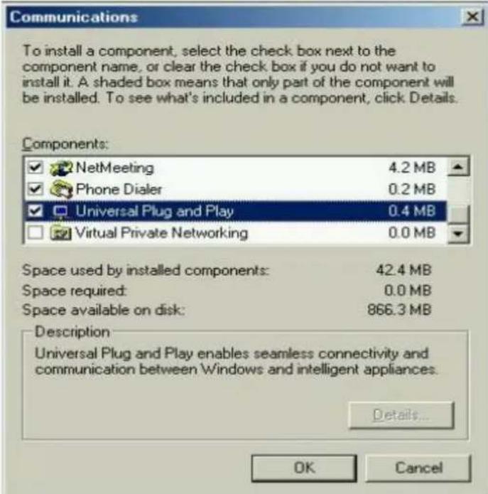
text_image
Communications To install a component, select the check box next to the component name, or clear the check box if you do not want to install it. A shaded box means that only part of the component will be installed. To see what's included in a component, click Details. Components: ✓ NetMeeting 4.2 MB ✓ Phone Dialer 0.2 MB ✓ Universal Plug and Play 0.4 MB ☐ Virtual Private Networking 0.0 MB Space used by installed components: 42.4 MB Space required: 0.0 MB Space available on disk: 866.3 MB Description Universal Plug and Play enables seamless connectivity and communication between Windows and intelligent appliances. Details... OK CancelStep 4: Click OK to go back to the Add/Remove Programs Properties window. Click Next.
Step 5: Restart the computer when prompted.
Follow the steps below to install the UPnP in Windows XP.
Step 1: Click Start and Control Panel.
Step 2: Double-click Network Connections.
Step 3: In the Network Connections window, click Advanced in the main menu and select Optional Networking Components ....
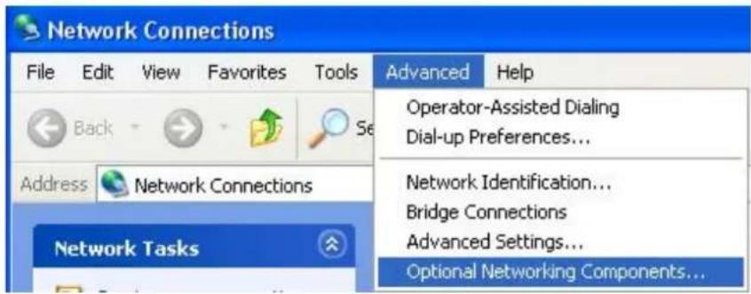
text_image
Network Connections File Edit View Favorites Tools Back Address Network Connections Network Tasks Advanced Help Operator-Assisted Dialing Dial-up Preferences... Network Identification... Bridge Connections Advanced Settings... Optional Networking Components...The Windows Optional Networking Components Wizard window displays.
Step 4: Select Networking Service in the Components selection box and click Details.
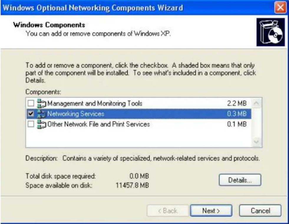
text_image
Windows Optional Networking Components Wizard Windows Components You can add or remove components of Windows XP. To add or remove a component, click the checkbox. A shaded box means that only part of the component will be installed. To see what's included in a component, click Details. Components: □ Management and Monitoring Tools 2.2 MB ✓ Networking Services 0.3 MB □ Other Network File and Print Services 0.1 MB Description: Contains a variety of specialized, network-related services and protocols. Total disk space required: 0.0 MB Space available on disk: 11457.8 MB Details... < Back Next > CancelStep 5: In the Networking Services window, select the Universal Plug and Play check box.
Step 6: Click OK to go back to the Windows Optional Networking Component Wizard window and click Next.
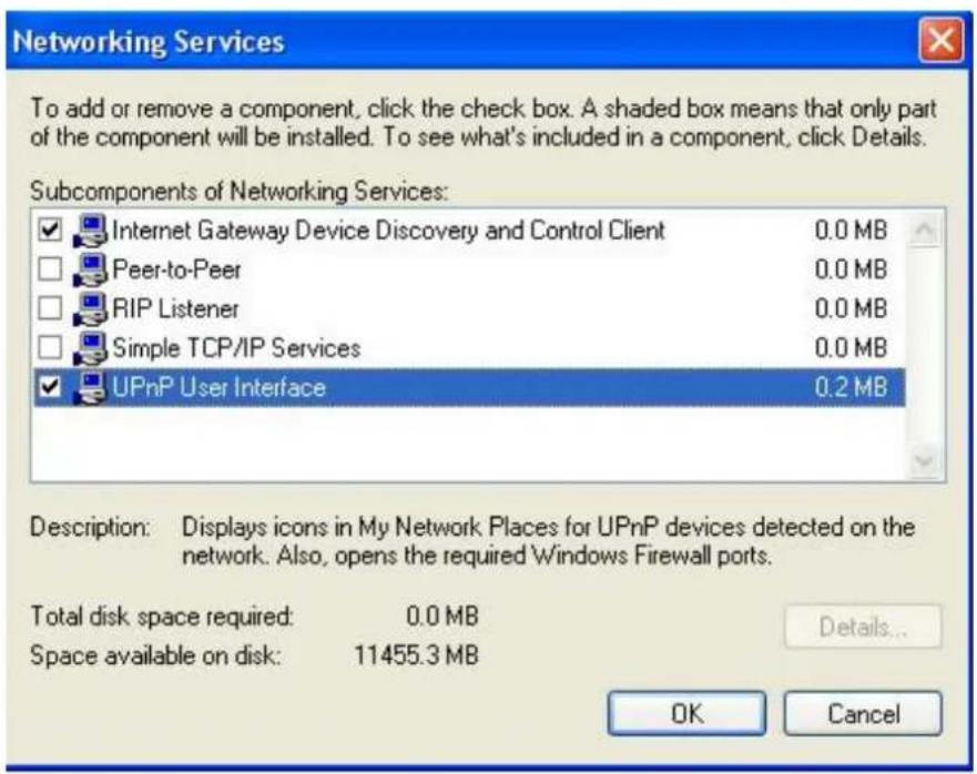
text_image
Networking Services To add or remove a component, click the check box. A shaded box means that only part of the component will be installed. To see what's included in a component, click Details. Subcomponents of Networking Services: ✓ Internet Gateway Device Discovery and Control Client 0.0 MB □ Peer-to-Peer 0.0 MB □ RIP Listener 0.0 MB □ Simple TCP/IP Services 0.0 MB ✓ UPnP User Interface 0.2 MB Description: Displays icons in My Network Places for UPnP devices detected on the network. Also, opens the required Windows Firewall ports. Total disk space required: 0.0 MB Space available on disk: 11455.3 MB Details... OK CancelAuto-discover Your UPnP-enabled Network Device
Step 1: Click start and Control Panel. Double-click Network Connections. An icon displays under Internet Gateway.
Step 2: Right-click the icon and select Properties.
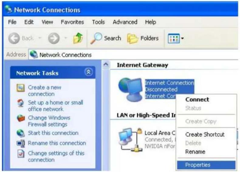
text_image
Network Connections File Edit View Favorites Tools Advanced Help Back Search Folders Address Network Connections Network Tasks Create a new connection Set up a home or small office network Change Windows Firewall settings Start this connection Rename this connection Change settings of this connection Internet Gateway Internet Connection Disconnected Internet Con LAN or High-Speed In Connect Status Create Copy Create Shortcut Delete Rename PropertiesStep 3: In the Internet Connection Properties window, click Settings to see the port mappings that were automatically created.
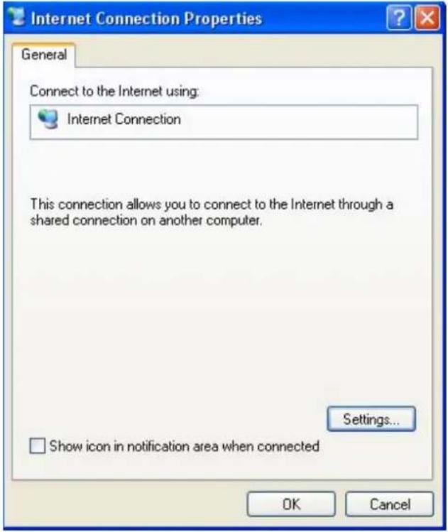
text_image
Internet Connection Properties General Connect to the Internet using: Internet Connection This connection allows you to connect to the Internet through a shared connection on another computer. Settings... □ Show icon in notification area when connected OK CancelStep 4: You may edit or delete the port mappings or click Add to manually add port mappings.
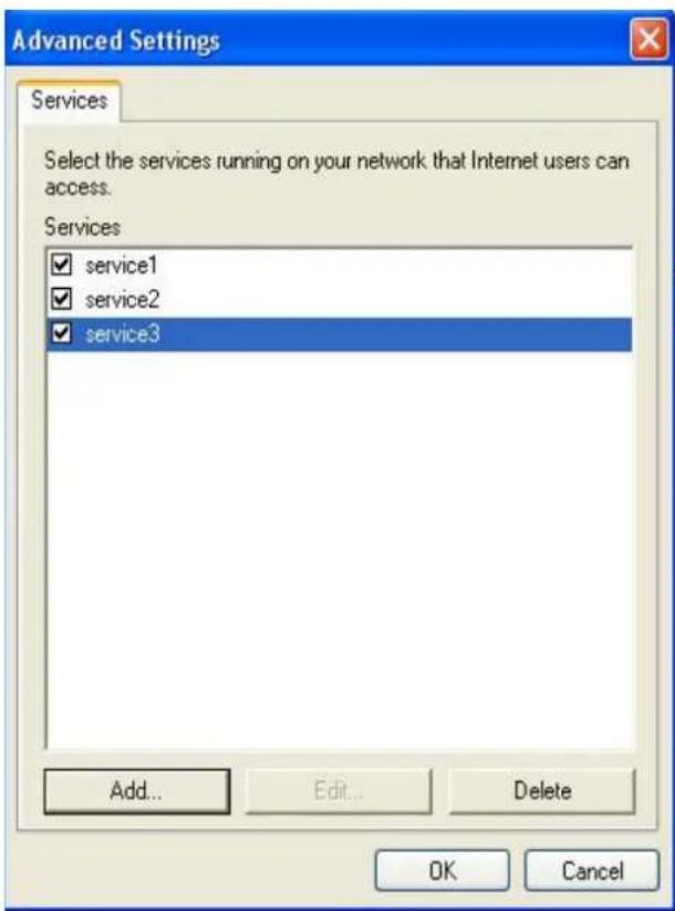
text_image
Advanced Settings Services Select the services running on your network that Internet users can access. Services ✓ service1 ✓ service2 ✓ service3 Add... Edit... Delete OK Cancel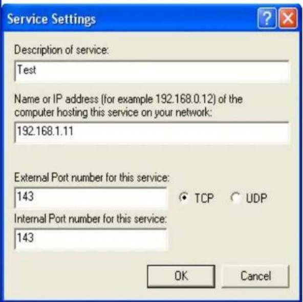
text_image
Service Settings Description of service: Test Name or IP address (for example 192.168.0.12) of the computer hosting this service on your network: 192.168.1.11 External Port number for this service: 143 Internal Port number for this service: 143 TCP UDP OK CancelStep 5: Select Show icon in notification area when connected option and click OK. An icon displays in the system tray
text_image
Internet Connection is now connected Click here for more information... upnp2 - Paint 6:43 PMStep 6: Double-click on the icon to display your current Internet connection status.
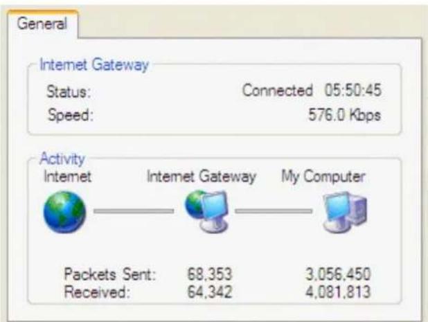
text_image
General Internet Gateway Status: Connected 05:50:45 Speed: 576.0 Kbps Activity Internet Internet Gateway My Computer Packets Sent: 68,353 3,056,450 Received: 64,342 4,081,813Web Configurator Easy Access
With UPnP, you can access web-based configuration for the BiPAC 7700N without first finding out the IP address of the router. This helps if you do not know the router's IP address. Follow the steps below to access web configuration.
Step 1: Click Start and then Control Panel.
Step 2: Double-click Network Connections.
Step 3: Select My Network Places under Other Places.
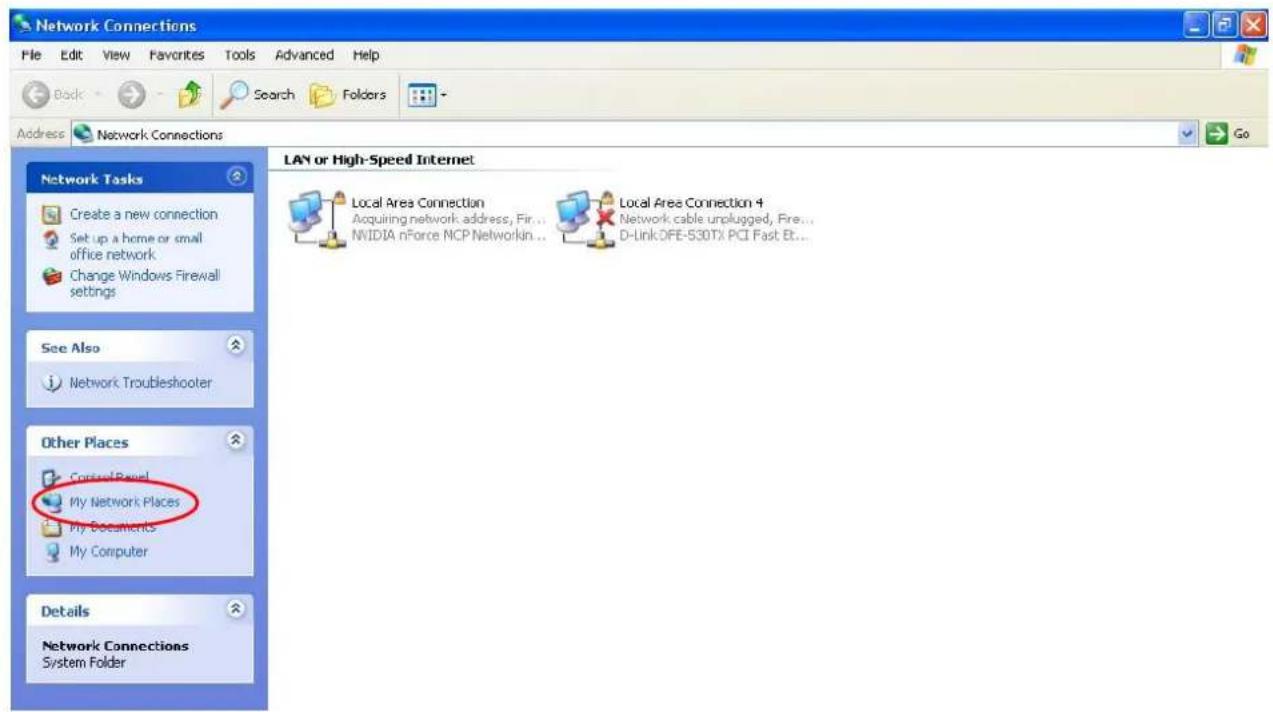
text_image
Network Connections File Edit View Favorites Tools Advanced Help Back Search Folders Address Network Connections LAN or High-Speed Internet Network Tasks Create a new connection Set up a home or small office network Change Windows Firewall settings See Also Network Troubleshooter Other Places Control Panel My Network Places My Documents My Computer Details Network Connections System Folder Local Area Connection Acquiring network address, Fir... NVIDIA nForce MCP Networkin... Local Area Connection 4 Network cable unplugged, Fire... D-Link DFE-S30TX PCI Fast Et...Step 4: An icon describing each UPnP-enabled device shows under Local Network.
Step 5: Right-click on the icon of your BiPAC 7700N and select Invoke. The web configuration login screen displays.
Step 6: Right-click on the icon of your BiPAC 7700N and select Properties. A properties window displays basic information about the BiPAC 7700N.
DNS Proxy
DNS proxy is used to forward request and response message between DNS Client and DNS Server. Hosts in LAN can use router serving as a DNS proxy to connect to the DNS Server in public to correctly resolve Domain name to access the internet.
DNS Proxy Configuration
Enable DNS Proxy
Host name of the Broadband Router: home.gateway
Domain name of the LAN network: home.gateway
Apply/Save
DNS Proxy: select whether to enable or disable DNS Proxy function, default is enabled.
Host name of the Broadband Router: enter the host name of the router. Default is home.gateway.
Domain name of the LAN network: enter the domain name of the LAN network. home.gateway.
Interface Grouping
Interface grouping is a function to group interfaces, known as VLAN. A Virtual LAN, commonly known as a VLAN, is a group of hosts with the common set of requirements that communicate as if they were attached to the same broadcast domain, regardless of the physical location. A VLAN has the same attributes as a physical LAN, but it allows for end stations to be grouped together even if they are not located on the same network switch.
Interface Grouping -- A maximum 16 entries can be configured
Interface Grouping supports multiple ports to PVC and bridging groups. Each group will perform as an independent network. To support this feature, you must create mapping groups with appropriate LAN and WAN interfaces using the Add button. The Remove button will remove the grouping and add the ungrouped interfaces to the Default group. Only the default group has IP interface.
| Group Name | Remove | WAN Interface | LAN Interfaces | DHCP Vendor IDs |
| Default | atm1.2 | LAN1 | ||
| LAN2 | ||||
| LAN3 | ||||
| LAN4 | ||||
| wlan0 |

Click Add to add groups. But note that the maximum number can be 16.
Group Name:
WAN Interface used in the grouping br_0_1_35/atm1.2
Grouped LAN Interfaces

Available LAN Interfaces
LAN4 LAN3 LAN2 LAN1 wlan0
Automatically Add Clients With the following DHCP Vendor IDs
Apply/Save
Group Name: type a group name.
WAN interface used in the grouping: select from the drop-down box the WAN interface you want to applied in the group.
Grouped LAN Interfaces: select the LAN interfaces you want to group as a single group from Available LAN Interfaces.
Automatically Add Clients With following DHCP Vendor IDs: enter the DHCP Vendor IDs for which you want the Clients automatically added into the group. DHCP vendor ID (DHCP 60) is an Authentication for DHCP Messages.
Click Apply/Save to confirm your settings and your added group will be listed in the Interface Grouping table below.
| Group Name | Remove | WAN Interface | LAN Interfaces | DHCP Vendor IDs |
| Default | LAN1 | |||
| LAN2 | ||||
| LAN3 | ||||
| wlan0 | ||||
| test | ☐ | atm1.2 | LAN4 |

If you want to remove the group, check the box as the following and press Remove.
| test | atm1.2 | LAN4 |

Note: If you like to automatically add LAN clients to a WAN Interface in the new group add the DHCP vendor ID string.
By configuring a DHCP vendor ID string any DHCP client request with the specified vendor ID (DHCP option 60) will be denied an IP address from the local DHCP server.
If a vendor ID is configured for a specific client device, please REBOOT the client device attached to the modem to allow it to obtain an appropriate IP address.
Each LAN interface can only be added into one group and one WAN interface can only be used in one group.
Multicast
Multicast is one of the three network transmission modes, Unicast, Multicast, Broadcast. It is a transmission mode that supports point-to-multipoint connections between the sender and the recipient. IGMP protocol is used to establish and maintain the relationship between IP host and the host directly connected multicast router.
IGMP stands for Internet Group Management Protocol is a communications protocols used to manage the membership of Internet Protocol multicast groups. IGMP is used by IP hosts and the adjacent multicast routers to establish multicast group members. There are three versions for IGMP, that is IGMPv1, IGMPv2 and IGMPv3.
IGMP Configuration
Enter IGMP protocol configuration fields if you want modify default values shown below.
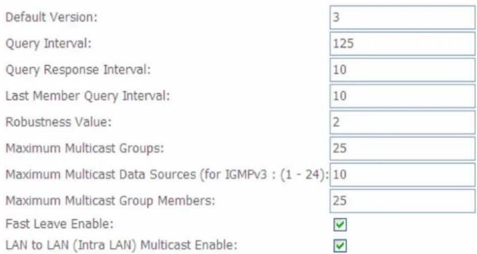
text_image
Default Version: 3 Query Interval: 125 Query Response Interval: 10 Last Member Query Interval: 10 Robustness Value: 2 Maximum Multicast Groups: 25 Maximum Multicast Data Sources (for IGMPv3 : (1 - 24): 10 Maximum Multicast Group Members: 25 Fast Leave Enable: ✓ LAN to LAN (Intra LAN) Multicast Enable: ✓Apply/Save
IGMP
Default Version: enter the supported IGMP version, 1-3, default is IGMP v3.
Query Interval: enter the periodic query interval time (sec) the multicast router sending the query message to hosts to understand the group membership information.
Query Response Interval: enter the response interval time (sec).
Last Member Query Interval: enter the interval time (sec) the multicast router query the specified group after it has received leave message.
Robustness Value: enter the router robustness parameter, 2-7, the greater the robustness value, the more robust the Querier is.
Maximum Multicast Groups: enter the Maximum Multicast Groups.
Maximum Multicast Data Sources( for IGMP v3): enter the Maximum Multicast Data Sources,1-24.
Maximum Multicast Group Members: enter the Maximum Multicast Group Members.
Fast leave: check to determine whether to support fast leave. If this value is enabled, IGMP proxy removes the membership of a group member immediately without sending an IGMP membership query on downstream. This is very helpful if user wants fast channel (group change) changing in cases like IPTV environment.
LAN to LAN (Intra LAN) Multicast: check to determine whether to support LAN to LAN (Intra LAN) Multicast. If user want to have a multicast data source on LAN side and he want to get IGMP snooping enabled, then this LAN-to-LAN multicast feature should be enabled.
Wireless
This section provides you ways to configure wireless access. When you click this item, the column will expand to display the sub-items that will lead you to configure your router.
Basic, Secturity, MAC Filter, Wireless Bridge, Advanced and Station Info are included here.
| Device Info |
| Quick Start |
| Advanced Setup |
| Wireless |
| Basic |
| Security |
| MAC Filter |
| Wireless Bridge |
| Advanced |
| Station Info |
| Diagnostics |
| Management |
Basic
It let you determine whether to enable Wireless function and set the basic parameters of an AP and the Virtual APs.
Wireless -- Basic
This page allows you to configure basic features of the wireless LAN interface. You can enable or disable the wireless LAN interface, hide the network from active scans, set the wireless network name (also known as SSID) and restrict the channel set based on country requirements.
Click "Apply/Save" to configure the basic wireless options.
Enable Wireless
Hide Access Point
Clients Isolation
Enable Wireless Multicast Forwarding (WMF)
SSID: wlan-ap
BSSID: 00:04:ed:77:00:02
Country: AUSTRALIA
Max Clients: 16
Wireless - Guest/Virtual Access Points:
| Enabled | SSID | Hidden | Isolate Clients | Enable WMF | Max Clients | BSSID |
| wl0_Guest1 | 16 | N/A | ||||
| wl0_Guest2 | 16 | N/A | ||||
| wl0_Guest3 | 16 | N/A |
Apply/Save
Enable Wireless: Default setting is set to Enable. If you do not have any wireless devices, check the checkbox again to unselect.
Hide Access Point: It is function in which transmits its SSID to the air so that when wireless client searches for a network, router can then be discovered and recognized. Check the checkbox to determine whether you want to hide SSID.
Clients Isolation: if you enabled this function, then each of your wireless clients will not be communicate with each other.
Wireless multicast Forwarding (WMF): check to enable or disable wireless multicast forwarding.
SSID: The SSID is the unique name of a wireless access point (AP) to be distinguished from another. For security purpose, change the default wlan-ap to a unique ID name to the AP already built-in to the router's wireless interface. It is case sensitive and must not excess 32 characters. Make sure your wireless clients have exactly the SSID as the device, in order to get connected to your network.
Note: SSID is case sensitive and must not excess 32 characters.
BSSID: Basic Set Service Identifier, it is a local managed IEEE MAC address, and is 48 bits value.
Country: Different countries have different wireless band resources, so you can select the appropriate Country according to the area where you want to device used.
Max Clients: enter the number of max clients the wireless network can supports,1-16.
Max-Guest/virtual Access points: A “Virtual Access Point” is a logical entity that exists within a physical Access Point (AP). When a single physical AP supports multiple “Virtual APs”, each Virtual AP appears to stations (STAs) to be an independent physical AP, even though only a single physical AP is present. For example, multiple Virtual APs might exist within a single physical AP, each advertising a distinct SSID and capability set. Alternatively, multiple Virtual APs might advertise the same SSID but a different capability set – allowing access to be provided via Web Portal, WEP, and WPA simultaneously. Where APs are shared by multiple providers, Virtual APs provide each provider with separate authentication and accounting data for their users, as well as diagnostic information, without sharing sensitive management traffic or data between providers. You can enable the virtual AP.
Here you can enable some Virtual APs according to the request. And the other parameters of virtual APs are the same to the above.
Click Apply to apply your settings.
Security
Wireless security is the prevention of unauthorized access or damage to computers using wireless network.
Wireless -- Security
This page allows you to configure security features of the wireless LAN interface.
You may setup configuration manually
OR
through WiFi Protected Setup(WPS)
WPS Setup
Enable WPS
Disabled
Manual Setup AP
You can set the network authentication method, selecting data encryption,
specify whether a network key is required to authenticate to this wireless network and specify the encryption strength.
Click "Apply/Save" when done.
Select SSID:
wlan-ap
Network Authentication:
Open
WEP Encryption:
Disabled
Apply/Save
Manual Setup AP
Select SSID: select the SSID you want these settings apply to.
Network Authentication
① Open
Network Authentication:
Open
WEP Encryption:
Encryption Strength:
Current Network Key:
Network Key 1:
Network Key 2:
Network Key 3:
Network Key 4:
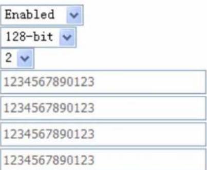
text_image
Enabled 128-bit 2 1234567890123 1234567890123 1234567890123 1234567890123Enter 13 ASCII characters or 26 hexadecimal digits for 128-bit encryption keys Enter 5 ASCII characters or 10 hexadecimal digits for 64-bit encryption keys
WEP Encryption: select to enable or disable WEP Encryption. Here select Enable.
Encryption Strength: select the strength, 128-bit or 64-bit.
Current Network Key: select the one to be the current network key. Please refer to key 1-4 below.
Network Key (1- 4): Enter 13 ASCII characters or 26 hexadecimal digits for 128-bit encryption keys.Enter 5 ASCII characters or 10 hexadecimal digits for 64-bit encryption keys.
i Shared
It is similar to network authentication 'Open'. But here the WEP Encryption must be enabled.
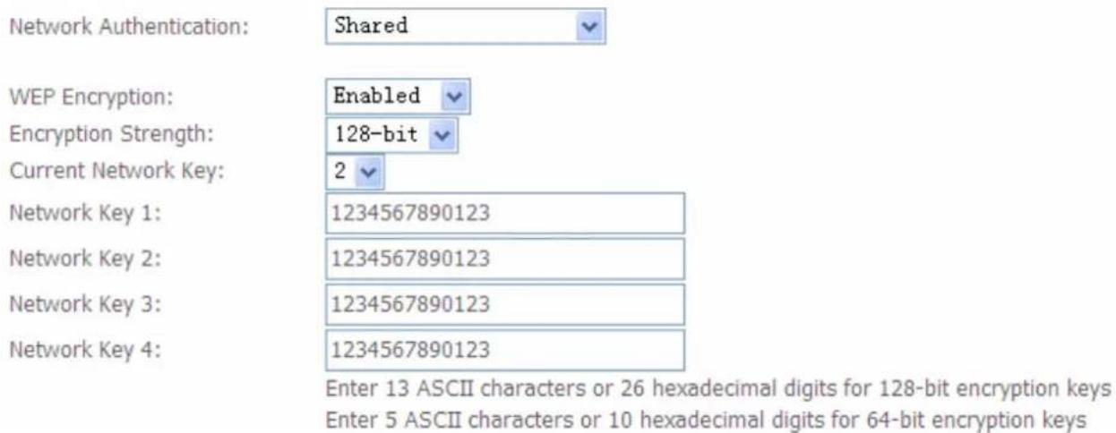
text_image
Network Authentication: Shared WEP Encryption: Enabled Encryption Strength: 128-bit Current Network Key: 2 Network Key 1: 1234567890123 Network Key 2: 1234567890123 Network Key 3: 1234567890123 Network Key 4: 1234567890123 Enter 13 ASCII characters or 26 hexadecimal digits for 128-bit encryption keys Enter 5 ASCII characters or 10 hexadecimal digits for 64-bit encryption keys① 802.1x
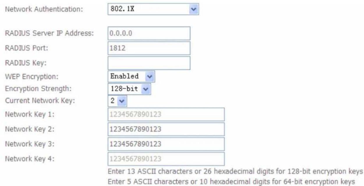
other
| Metric | Value | | --- | --- | | Network Authentication | 802.1X | | RADIUS Server IP Address | 0.0.0.0 | | RADIUS Port | 1812 | | RADIUS Key | | | WEP Encryption | Enabled | | Encryption Strength | 128-bit | | Current Network Key | 2 | | Network Key 1 | 1234567890123 | | Network Key 2 | 1234567890123 | | Network Key 3 | 1234567890123 | | Network Key 4 | 1234567890123 | Enter 13 ASCII characters or 26 hexadecimal digits for 128-bit encryption keys Enter 5 ASCII characters or 10 hexadecimal digits for 64-bit encryption keysRADIUS Server IP Address: RADIUS( Remote Authentication Dial In User Service), Enter the IP address of RADIUS authentication server.
RADIUS Server Port: Enter the port number of RADIUS authentication server here.
RADIUS Key: Enter the password of RADIUS authentication server.
WEP Encryption: select to enable or disable WEP Encryption. Here select Enable.
Current Network Key: select the one to be the current network key. Please refer to key 2-3 below.
Network Key (1- 4): Enter 13 ASCII characters or 26 hexadecimal digits for 128-bit encryption keys.Enter 5 ASCII characters or 10 hexadecimal digits for 64-bit encryption keys.
i WPA
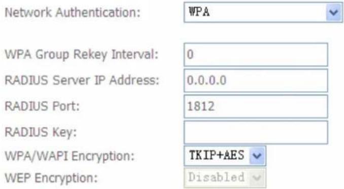
text_image
Network Authentication: WPA WPA Group Rekey Interval: 0 RADIUS Server IP Address: 0.0.0.0 RADIUS Port: 1812 RADIUS Key: WPA/WAPI Encryption: TKIP+AES WEP Encryption: DisabledWPA Group ReKey Internal: The period of renewal time for changing the security key automatically between wireless client and Access Point (AP). The unit is second.
RADIUS Server IP Address: RADIUS( Remote Authentication Dial In User Service), Enter the IP address of RADIUS authentication server.
RADIUS Server Port: Enter the port number of RADIUS authentication server here.
RADIUS Key: Enter the password of RADIUS authentication server.
WPA/WAPI Encryption: There are two Algorithms, AES (Advanced Encryption Standard) and TKIP(Temporal Key Integrity Protocol) which help to protect the wireless communication.
① WPA-PSK / WPA2-PSK
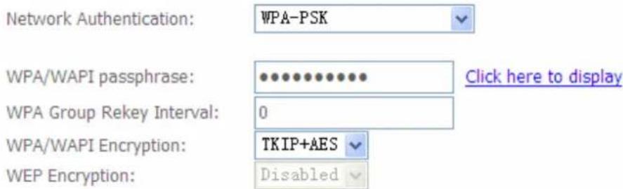
text_image
Network Authentication: WPA-PSK WPA/WAPI passphrase: •••••••••••••• WPA Group Rekey Interval: 0 WPA/WAPI Encryption: TKIP+AES WEP Encryption: DisabledWPA/WAPI passphrase: enter the WPA.WAPI passphrase, you can click here to display to view it.
WPA Group ReKey Internal: The period of renewal time for changing the security key automatically between wireless client and Access Point (AP). The unit is second.
WPA/WAPI Encryption: There are two Algorithms, AES (Advanced Encryption Standard) and TKIP(Temporal Key Integrity Protocol) which help to protect the wireless communication.
① WPA2
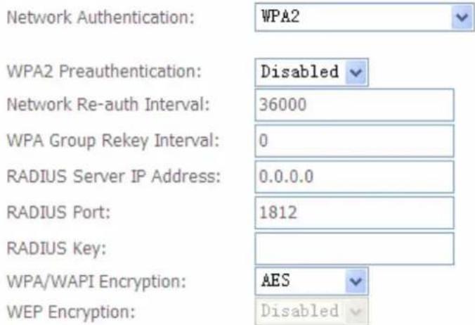
text_image
Network Authentication: WPA2 WPA2 Preauthentication: Disabled Network Re-auth Interval: 36000 WPA Group Rekey Interval: 0 RADIUS Server IP Address: 0.0.0.0 RADIUS Port: 1812 RADIUS Key: WPA/WAPI Encryption: AES WEP Encryption: DisabledWPA2 Preauthentication: When a wireless client wants to handoff to another AP, with preauthentication, it can perform 802.1X authentications to the new AP, and when handoff happens, this mode will help reduce the association time used.
Network Re-auth Interval: the interval for network Re-authentication. The unit is second.
WPA Group ReKey Internal: The period of renewal time for changing the security key automatically between wireless client and Access Point (AP). The unit is second.
RADIUS Server IP Address: RADIUS( Remote Authentication Dial In User Service), Enter the IP address of RADIUS authentication server. The unit is second.
RADIUS Server Port: Enter the port number of RADIUS authentication server here.
RADIUS Key: Enter the password of RADIUS authentication server.
WPA/WAPI Encryption: There are two Algorithms, AES (Advanced Encryption Standard) and TKIP(Temporal Key Integrity Protocol) which help to protect the wireless communication.
① Mixed WPA2/WPA
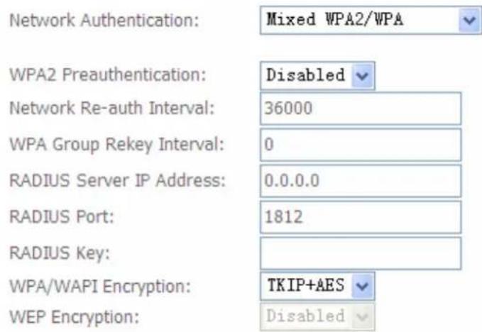
text_image
Network Authentication: Mixed WPA2/WPA WPA2 Preauthentication: Disabled Network Re-auth Interval: 36000 WPA Group Rekey Interval: 0 RADIUS Server IP Address: 0.0.0.0 RADIUS Port: 1812 RADIUS Key: WPA/WAPI Encryption: TKIP+AES WEP Encryption: DisabledWPA2 Preauthentication: When a wireless client wants to handoff to another AP, with preauthentication, it can perform 802.1X authentications to the new AP, and when handoff happens, this mode will help reduce the association time used.
Network Re-auth Interval: the interval for network Re-authentication. The unit is second.
WPA Group ReKey Internal: The period of renewal time for changing the security key automatically between wireless client and Access Point (AP). The unit is second.
RADIUS Server IP Address: RADIUS( Remote Authentication Dial In User Service), Enter
the IP address of RADIUS authentication server.
RADIUS Server Port: Enter the port number of RADIUS authentication server here.
RADIUS Key: Enter the password of RADIUS authentication server.
WPA/WAPI Encryption: There are two Algorithms, AES (Advanced Encryption Standard) and TKIP(Temporal Key Integrity Protocol) which help to protect the wireless communication.
① Mixed WPA2/WPA-PSk
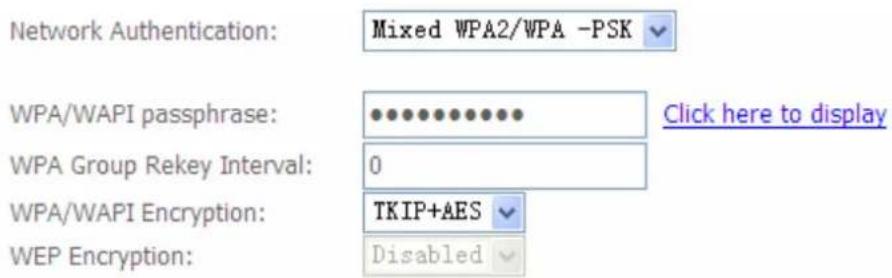
WPA/WAPI passphrase: enter the WPA.WAPI passphrase, you can click here to display to view it.
WPA Group ReKey Internal: The period of renewal time for changing the security key automatically between wireless client and Access Point (AP). The unit is second.
WPA/WAPI Encryption: There are two Algorithms, AES (Advanced Encryption Standard) and TKIP(Temporal Key Integrity Protocol) which help to protect the wireless communication.
WPS Setup
WPS (Wi-Fi Protected Setup) feature is a standard protocol created by Wi-Fi Alliance. WPS is used to exchange the AP setting with Station and configure AP setting. This feature greatly simplifies the steps needed to create a Wi-Fi network for a residential or an office setting. WPS supports 2 types of configuration methods which are commonly known among consumers: PIN Method & PBC Method.
WPS: select enable to enable WPS function. As you see, WPS can only be available when WPA-PSK, WPA2 PSK or OPEN mode is configured.
Note: here wireless can be configured as Registrar and Enrolee mode respectively. When AP is configured as Registrar, you should select Configured in the WPS AP Mode below, and default WPS AP Mode is Configured. When AP is configured as Enrolee, the WPS AP Mode below should be changed to Unconfigured. Follow the following steps.
WPS Setup
Enable WPS
Enabled
Add Client (This feature is available only when WPA-PSK, WPA2 PSK or OPEN mode is configured)

Push-Button

PIN
Add Enrolee

Help
Set WPS AP Mode
Configured

Setup AP (Configure all security settings with an external registar)

Push-Button

PIN
Config AP
Device PIN

229909
Help
Manual Setup AP
You can set the network authentication method, selecting data encryption, specify whether a network key is required to authenticate to this wireless network and specify the encryption strength. Click "Apply/Save" when done.
Select SSID:
wlan-ap
Network Authentication:
Open

WEP Encryption:
Disabled
Apply/Save
Configure AP as Registrar
Add Enrollee with PIN method
- Select radio button 'PIN'.
- Input PIN from Enrollee Station (16837546 in this example). Help: it is to help users to understand PIN.
- Click Add Enrolee
WPS Setup
Enable WPS
Add Client (This feature is available only when WPA-PSK, WPA2 PSK or OPEN mode is configured)

Push-Button

PIN
Add Enrolee
16837546
Help
Set WPS AP Mode
Configured

Setup AP (Configure all security settings with an external registar)

Push-Button

Config AP
Device PIN
76229909
Help
Manual Setup AP
You can set the network authentication method, selecting data encryption, specify whether a network key is required to authenticate to this wireless network and specify the encryption strength. Click "Apply/Save" when done.
Select SSID:
wlan-ap

Network Authentication:
Open

WEP Encryption:
Disabled

Apply/Save
- Operate Station to start WPS Adding Enrollee. Launch the wireless client's WPS utility (eg.Ralink Utility). Set the Config Mode as Enrollee, press the WPS button on the top bar, select the AP (eg.wlan-ap) from the WPS AP List column. Then press the PIN button located on the middle left of the page to run the scan.
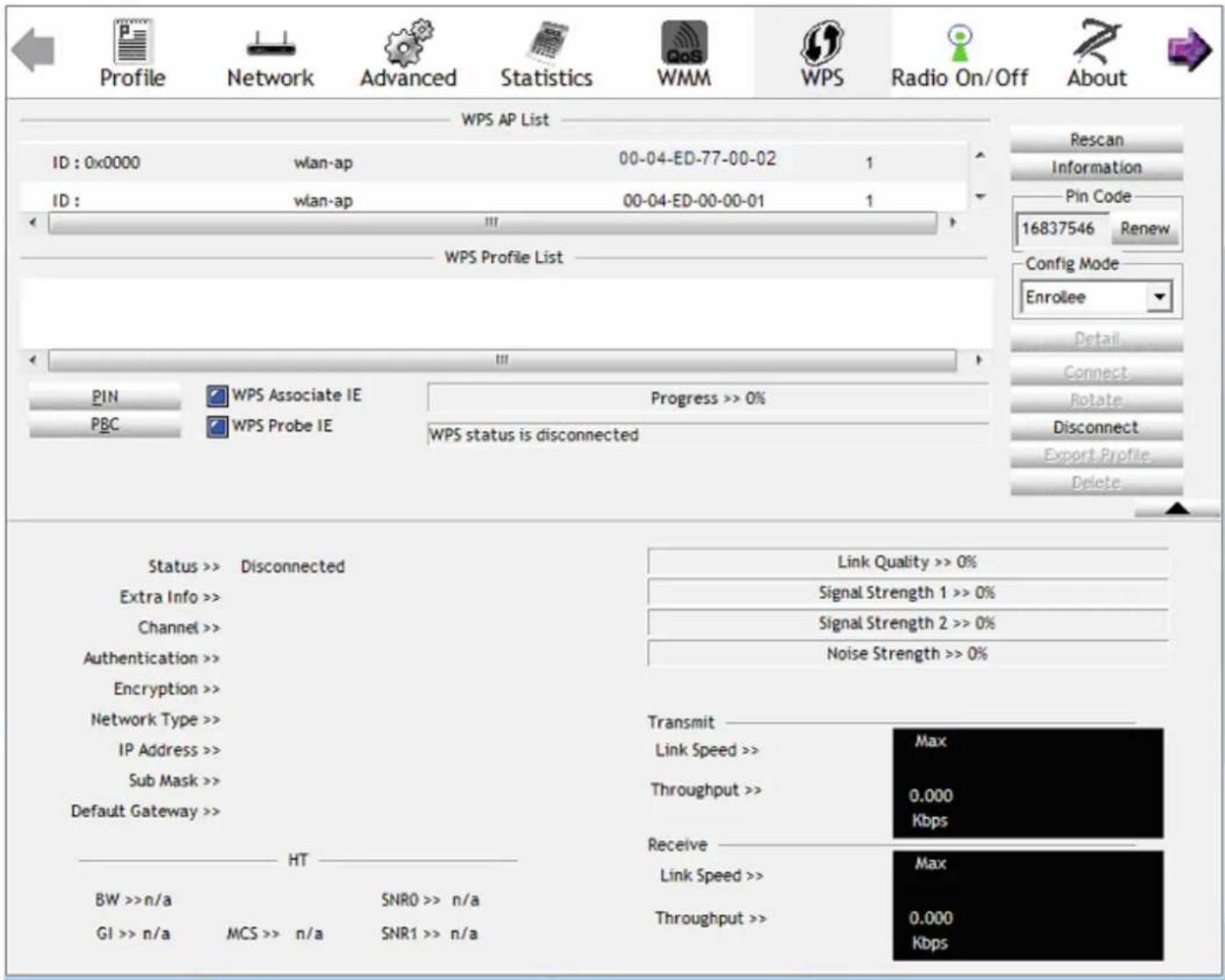
text_image
Profile Network Advanced Statistics WMM WPS Radio On/Off About WPS AP List ID : 0x0000 wlan-ap 00-04-ED-77-00-02 1 ID : wlan-ap 00-04-ED-00-00-01 1 WPS Profile List PIN WPS Associate IE Progress >> 0% PBC WPS Probe IE WPS status is disconnected Status >> Disconnected Extra Info >> Channel >> Authentication >> Encryption >> Network Type >> IP Address >> Sub Mask >> Default Gateway >> HT BW >> n/a SNR0 >> n/a GI >> n/a MCS >> n/a SNR1 >> n/a Link Quality >> 0% Signal Strength 1 >> 0% Signal Strength 2 >> 0% Noise Strength >> 0% Transmit Link Speed >> Max Throughput >> 0.000 Kbps Receive Link Speed >> Max Throughput >> 0.000 Kbps- The client's SSID and security setting will now be configured to match the SSID and security setting of the registrar.
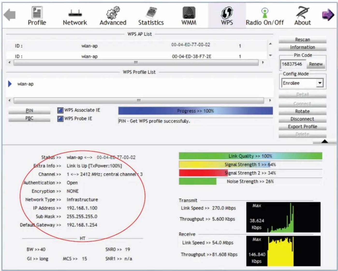
text_image
Profile Network Advanced Statistics WMM WPS Radio On/Off About WPS AP List ID : wlan-ap 00-04-ED-77-00-02 1 ID : wlan-ap 00-04-ED-38-F7-2E 1 WPS Profile List wlan-ap PIN WPS Associate IE Progress >> 100% PBC WPS Probe IE PIN - Get WPS profile successfully. Status >> wlan-ap <--> 00-04-ED 77-00-02 Extra Info >> Link is Up [TxPower:100%] Channel >> 1 <--> 2412 MHz; central channel: 3 Authentication >> Open Encryption >> NONE Network Type >> Infrastructure IP Address >> 192.168.1.100 Sub Mask >> 255.255.255.0 Default Gateway >> 192.168.1.254 HT BW >>40 SNRO >> 19 GI >> long MCS >> 15 SNR1 >> n/a Link Quality >> 100% Signal Strength 1 >> 64% Signal Strength 2 >> 34% Noise Strength >> 26% Transmit Link Speed >> 270.0 Mbps Max Throughput >> 5.600 Kbps 38.624 Kbps Receive Link Speed >> 54.0 Mbps Max Throughput >>81.608 Kbps 146.840 KbpsYou can check the message in the red ellipse with the security parameters you set, here we all use the default.
Add Enrollee with PBC Method
- Select radio button "Push-Button" and Click Or Press the physical button on router.
WPS Setup
Enable WPS
Enabled

Add Client (This feature is available only when WPA-PSK, WPA2 PSK or OPEN mode is configured)
Push-Button
PIN
Add Enrolee
Set WPS AP Mode
Configured

Setup AP (Configure all security settings with an external registar)
○ Push-Button
PIN
Config AP
Device PIN
76229909
Help
Manual Setup AP
You can set the network authentication method, selecting data encryption, specify whether a network key is required to authenticate to this wireless network and specify the encryption strength. Click "Apply/Save" when done.
Select SSID:
wlan-ap

Network Authentication:
Open

WEP Encryption:
Disabled

Apply/Save
- Operate Station to start WPS Adding Enrollee. Launch the wireless client's WPS Utility (eg. Ralink Utility). Set the Config Mode as Enrollee. Then press the WPS button and choose the correct AP (eg. wlan-ap) from the WPS AP List section before pressing the PBC button to run the scan.
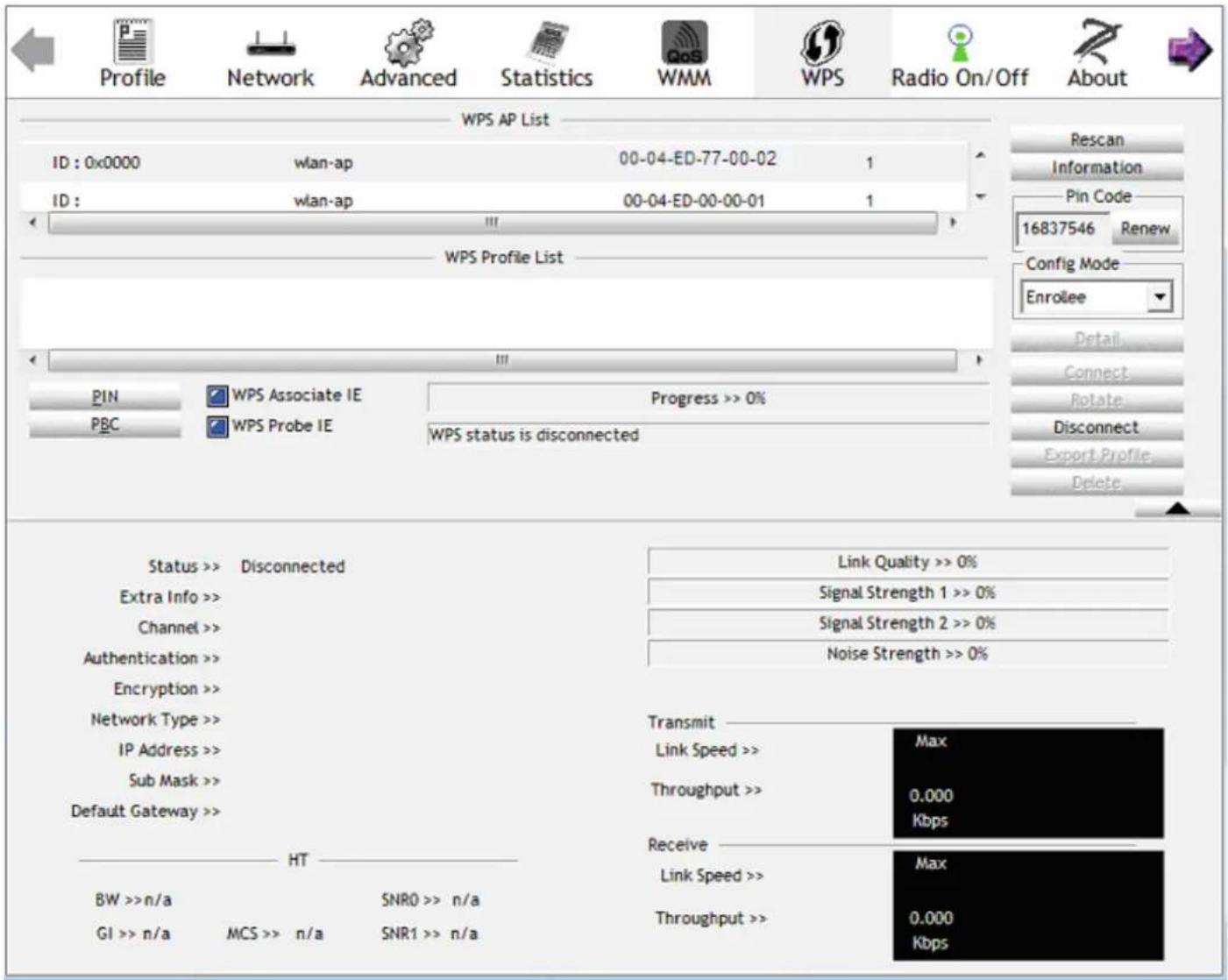
text_image
Profile Network Advanced Statistics WMM WPS Radio On/Off About WPS AP List ID : 0x0000 wlan-ap 00-04-ED-77-00-02 1 ID : wlan-ap 00-04-ED-00-00-01 1 WPS Profile List PINS WPS Associate IE Progress >> 0% PBC WPS Probe IE WPS status is disconnected Status >> Disconnected Extra Info >> Channel >> Authentication >> Encryption >> Network Type >> IP Address >> Sub Mask >> Default Gateway >> HT BW >> n/a SNRO >> n/a GI >> n/a MCS >> n/a SNR1 >> n/a Link Quality >> 0% Signal Strength 1 >> 0% Signal Strength 2 >> 0% Noise Strength >> 0% Transmit Link Speed >> Max Throughput >> 0.000 Kbps Receive Link Speed >> Max Throughput >> 0.000 Kbps- When the PBC button is pushed, a wireless communication will be established between your router and the PC. The client's SSID and security setting will now be configured to match the SSID and security setting of the router.
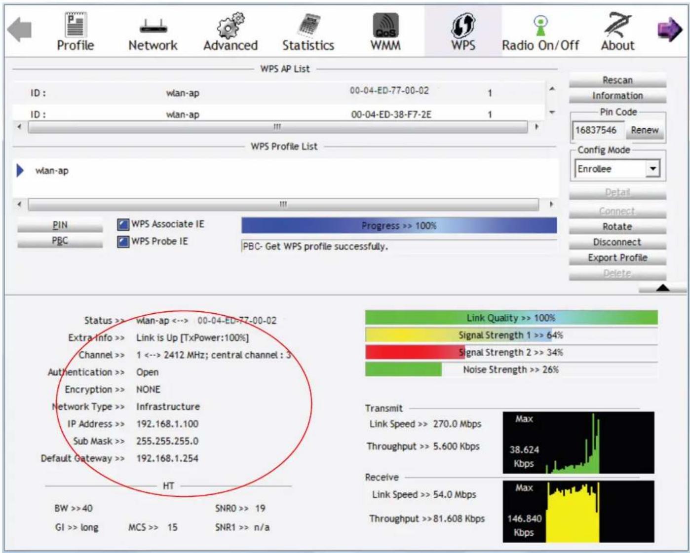
text_image
Profile Network Advanced Statistics WMM WPS Radio On/Off About WPS AP List ID : wlan-ap 00-04-ED-77-00-02 1 ID : wlan-ap 00-04-ED-38-F7-2E 1 WPS Profile List wian-ap PIN WPS Associate IE Progress >> 100% PBC WPS Probe IE PBC- Get WPS profile successfully. Status >> wlan-ap <--> 00-04-ED-77-00-02 Extra Info >> Link is Up [TxPower:100%] Channel >> 1 <--> 2412 MHz; central channel : 3 Authentication >> Open Encryption >> NONE Network Type >> Infrastructure IP Address >> 192.168.1.100 Sub Mask >> 255.255.255.0 Default Gateway >> 192.168.1.254 HT BW >> 40 SNRO >> 19 GI >> long MCS >> 15 SNR1 >> n/a Link Quality >> 100% Signal Strength 1 >> 64% Signal Strength 2 >> 34% Noise Strength >> 26% Transmit Link Speed >> 270.0 Mbps Max Throughput >> 5.600 Kbps 38.624 Kbps Receive Link Speed >> 54.0 Mbps Max Throughput >>81.608 Kbps 146.840 KbpsConfigure AP as Enrollee
- Add Registrar with PIN Method
- Set AP to "Unconfigured Mode" and Click "Config AP" button.
WPS Setup
Enable WPS
Add Client (This feature is available only when WPA-PSK, WPA2 PSK or OPEN mode is configured)

Push-Button

PIN
Add Enrolee

Help
Set WPS AP Mode

Setup AP (Configure all security settings with an external registar)

Push-Button

PIN
Config AP
Device PIN
76229909
Help
Manual Setup AP
You can set the network authentication method, selecting data encryption,
specify whether a network key is required to authenticate to this wireless network and specify the encryption strength. Click "Apply/Save" when done.
Select SSID:
wlan-ap

Network Authentication:
Open

WEP Encryption:
Disabled

Apply/Save
- Launch the wireless client's WPS utility (eg. Ralink Utility). Set the Config Mode as Registrar. Enter the PIN number (76229909 for example) in the PIN Code column then choose the correct AP (eg. wlan-ap) from the WPS AP List section before pressing the PIN button to run the scan.
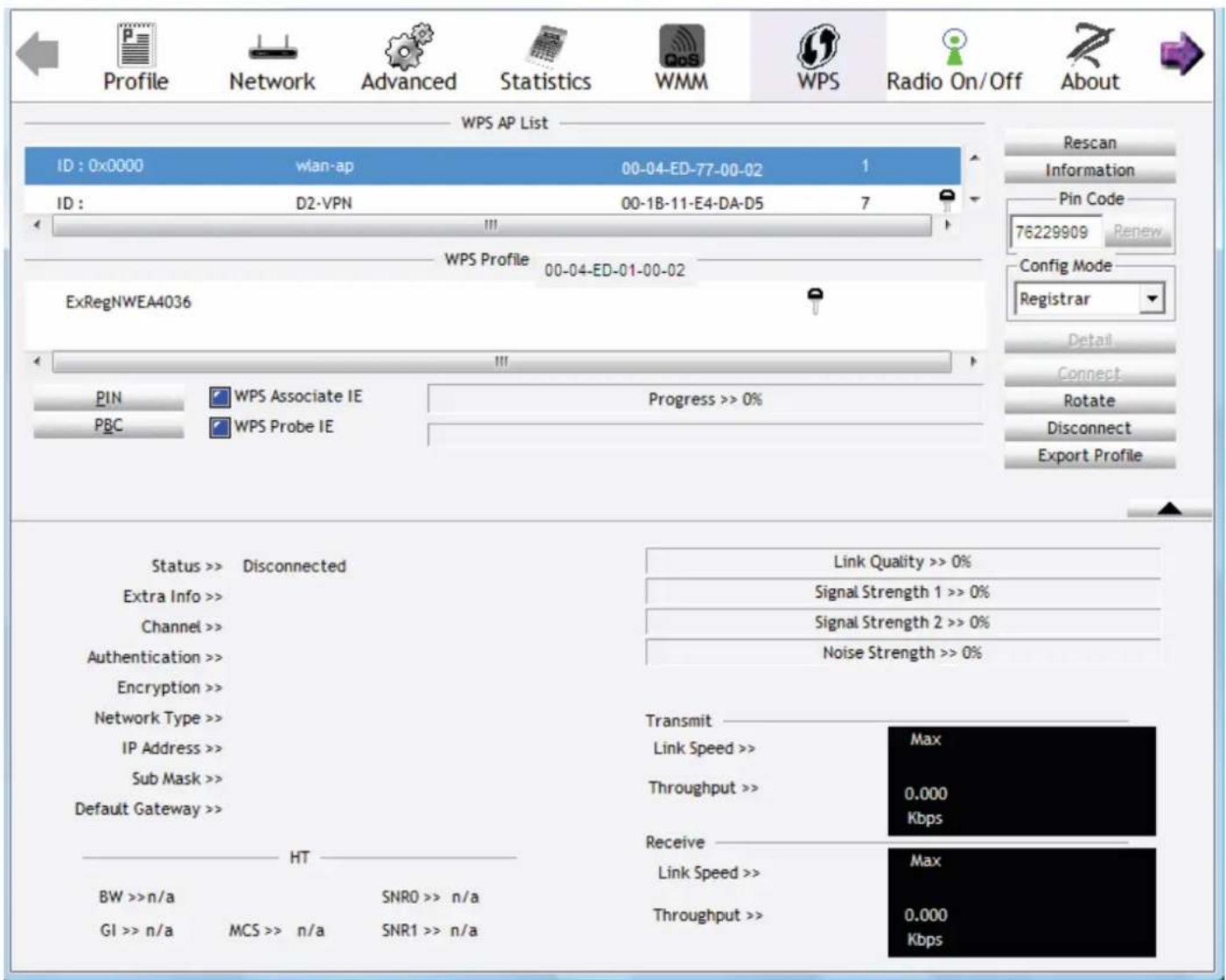
text_image
Profile Network Advanced Statistics WMM WPS Radio On/Off About WPS AP List ID : 0x0000 wian-ap 00-04-ED-77-00-02 1 ID : D2-VPN 00-1B-11-E4-DA-D5 7 WPS Profile 00-04-ED-01-00-02 ExRegNWEA4036 PIN WPS Associate IE Progress >> 0% PBC WPS Probe IE Status >> Disconnected Extra Info >> Channel >> Authentication >> Encryption >> Network Type >> IP Address >> Sub Mask >> Default Gateway >> HT BW >> n/a GI >> n/a MCS >> n/a SNRO >> n/a SNR1 >> n/a Link Quality >> 0% Signal Strength 1 >> 0% Signal Strength 2 >> 0% Noise Strength >> 0% Transmit Link Speed >> Max Throughput >> 0.000 Kbps Receive Link Speed >> Max Throughput >> 0.000 Kbps- The router's (AP's) SSID and security setting will now be configured to match the SSID and security setting of the registrar.
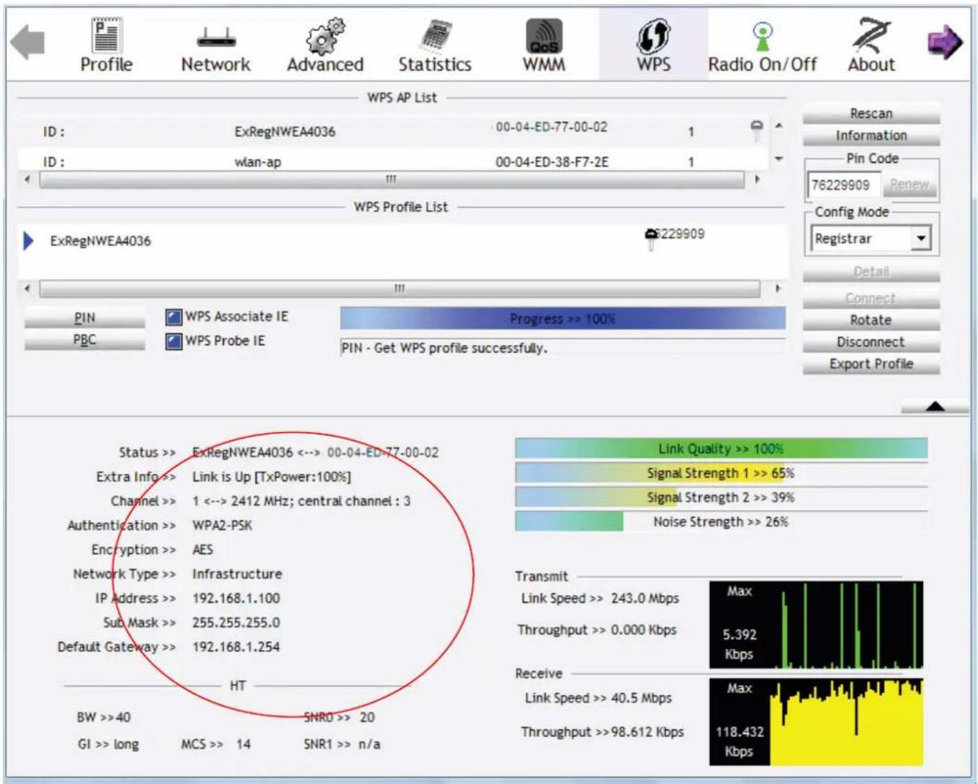
text_image
Profile Network Advanced Statistics WMM WPS Radio On/Off About WPS AP List ID : ExRegNWEA4036 00-04-ED-77-00-02 1 ID : wlan-ap 00-04-ED-38-F7-2E 1 WPS Profile List ExRegNWEA4036 6229909 PIN WPS Associate IE Progress >> 100% PBC WPS Probe IE PIN - Get WPS profile successfully. Status >> ExRegNWEA4036 <-> 00-04-ED-77-00-02 Extra Info >> Link is Up [TxPower:100%] Channel >> 1 <-> 2412 MHz; central channel : 3 Authentication >> WPA2-PSK Encryption >> AES Network Type >> Infrastructure IP Address >> 192.168.1.100 Sub Mask >> 255.255.255.0 Default Gateway >> 192.168.1.254 HT BW >>40 SNRO >> 20 GI >> long MCS >> 14 SNR1 >> n/a Link Quality >> 100% Signal Strength 1 >> 65% Signal Strength 2 >> 39% Noise Strength >> 26% Transmit Link Speed >> 243.0 Mbps Max Throughput >> 0.000 Kbps 5.392 Kbps Receive Link Speed >> 40.5 Mbps Max Throughput >>98.612 Kbps 118.432 Kbps- Do Web Page refresh after ER complete AP Configuration to check the new parameters setting.
MAC Filter
Wireless -- MAC Filter
Select SSID: wlan-ap
MAC Restrict Mode: ● Disabled ○ Allow ○ Deny
MAC Address Remove
Add Remove
Select SSID: select the SSID you want this filter applies to.
MAC Restrict Mode:
① Disable: disable the MAC Filter function.
① Allow: allow the hosts with the listed MACs to access the wireless network.
① Deny: deny the hosts with the listed MACs to access the wireless network.
You can change the mode to allow or deny the MACs in the list to access the wireless network.
Select the MAC restrict mode (here Deny for example), then Click Add to add the MACs.
Wireless -- MAC Filter
Enter the MAC address and click "Apply/Save" to add the MAC address to the wireless MAC address filters.
MAC Address:
Apply/Save
MAC Address: enter the MAC address(es). The format of MAC address could be: xx:xx:xx:xx:xx:xx.
Click Apply/Save to apply your settings and the item will be listed below.
Wireless -- MAC Filter
Select SSID: wlan-ap
MAC Restrict Mode: ○ Disabled ○ Allow ● Deny
| MAC Address | Remove |
| 00:13:CE:29:A1:50 |
Add Remove
Wireless -- MAC Filter
Select SSID: wlan-ap
MAC Restrict Mode: ○ Disabled ○ Allow ● Deny
| MAC Address | Remove |
| 00:13:CE:29:A1:50 |
Add Remove
If you need not the rules, check the remove checkbox and press Remove to delete it.
Wireless Bridge
WDS (wireless distributed system) is a wireless access point mode that enables wireless link and communication with other access point. It is easy to be installed, simply define the peer's MAC address of the connected AP. WDS takes advantages of cost saving and flexibility which no extra wireless client device is required to bridge between two access points and extending an existing wired or wireless infrastructure network to create a larger network.
Here you can select to decide what role the AP servers as, AP or wireless bridge (WDS).
Wireless -- Bridge
This page allows you to configure wireless bridge features of the wireless LAN interface. You can select Wireless Bridge (also known as Wireless Distribution System) to disable access point functionality. Selecting Access Point enables access point functionality. Wireless bridge functionality will still be available and wireless stations will be able to associate to the AP. Select Disabled in Bridge Restrict which disables wireless bridge restriction. Any wireless bridge will be granted access. Selecting Enabled or Enabled(Scan) enables wireless bridge restriction. Only those bridges selected in Remote Bridges will be granted access.
Click "Refresh" to update the remote bridges. Wait for few seconds to update.
Click "Apply/Save" to configure the wireless bridge options.
AP Mode:
Access Point

Bridge Restrict:
Enabled

Remote Bridges MAC Address:




Refresh
Apply/Save
AP Mode: determines whether the gateway will act as an Access point or as a Bridge.
① Access Point: the gateway communicates with both clients and bridges.
① Wireless Bridge: the gateway communicates with other WDS devices only. In this mode, the gateway doesn't communicate with client devices.
If your wireless network includes repeaters that use WDS, the gateway in wireless bridge mode will also communicate with your repeaters. The gateway in wireless bridge mode will not communicate with a repeater that uses a proprietary (non-WDS) mode.
Bridge Restrict: this feature determines whether the gateway will communicate with all other bridges or only specific ones:
① Enable: to enable wireless bridge restriction. Only those specified in the Remote MAC Address the gateway can communicate with.
Bridge Restrict:
Remote Bridges MAC Address:


Remote Bridge MAC Address: enter the remote bridge MAC addresses. Here up to 4 bridge MAC addresses are supported.
① Enabled (Scan): to enable wireless bridge restriction. Only those been scanned the gateway can communicate with.
Bridge Restrict:
Remote Bridges MAC Address:
| SSID | BSSID | |
| wlan-ap | 00:04:ED:AF:BC:ED | |
| wlan-ap | 00:04:ED:73:00:05 | |
| HotSpot | 00:24:97:45:A1:AC | |
| yxlink.com | 00:24:97:45:A1:AD | |
| wlan-ap | 00:04:ED:01:23:40 | |
| wlan-ap | 00:04:ED:AC:78:85 | |
| ChinaNet | 00:23:89:BA:08:F0 |
Remote Bridge MAC Address: select the remote bridge MAC addresses.
① Disable: Does not restrict the gateway to communicating with bridges that have their MAC address listed, but it is still open to communicate with all bridges that are in the same network.
Bridge Restrict:

Click Apply/Save to apply your settings.
Advanced
Here users can set some advanced parameters about wireless.
Wireless -- Advanced
This page allows you to configure advanced features of the wireless LAN interface. You can select a particular channel on which to operate, force the transmission rate to a particular speed, set the fragmentation threshold, set the RTS threshold set the wakeup interval for clients in power-save mode, set the beacon interval for the access point, set XPress mode and set whether short or long preambles are used.
Click "Apply/Save" to configure the advanced wireless options.
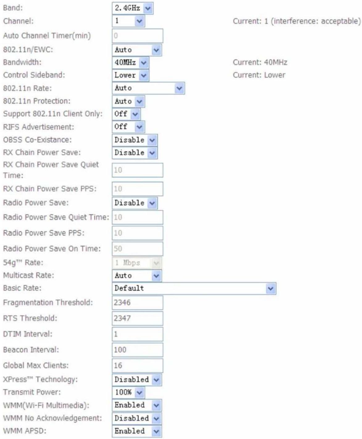
bar
| Parameter | Value | | :--- | :--- | | Band: | 2.4GHz | | Channel: | 1 | | Auto Channel Timer(min) | 0 | | 802.11n/EWC: | Auto | | Bandwidth: | 40MHz | | Control Sideband: | Lower | | 802.11n Rate: | Auto | | 802.11n Protection: | Auto | | Support 802.11n Client Only: | Off | | RIFS Advertisement: | Off | | OBSS Co-Existence: | Disable | | RX Chain Power Save: | Disable | | RX Chain Power Save Quiet Time: | 10 | | RX Chain Power Save PPS: | 10 | | Radio Power Save: | Disable | | Radio Power Save Quiet Time: | 10 | | Radio Power Save PPS: | 10 | | Radio Power Save On Time: | 50 | | 54g™ Rate: | 1 Mbps | | Multicast Rate: | Auto | | Basic Rate: | Default | | Fragmentation Threshold: | 2346 | | RTS Threshold: | 2347 | | DTIM Interval: | 1 | | Beacon Interval: | 100 | | Global Max Clients: | 16 | | XPress™ Technology: | Disabled | | Transmit Power: | 100% | | WMM(Wi-Fi Multimedia): | Enabled | | WMM No Acknowledgement: | Disabled | | WMM APSD: | Enabled | Current: 1 (interference: acceptable)
Band: select frequency band. Here 2.4GHz.
Channel: Allows channel selection of a specific channel (1-7) or Auto mode.
Auto Channel Timer(min): the auto channel times length it takes to scan in minutes. Only available for auto channel mode.
802.11n/EWC: select to auto enable or disable 802.11n.
Bandwidth: Select bandwidth. The higher the bandwidth the better the performance will be.
Control Sideband: only available for 40MHz. It allows you to select upper sideband or lower sideband. Sideband refers to the frequency band either above (upper sideband) or below (lower sideband) the carrier frequency, within which fall the spectral components produced by modulation of a carrier wave.
802.11n Rate: It allows you to select the fixed transmission rate or auto.
802.11n Protection: turn off for maximized throughput. Auto for greater security.
Support 802.11n Client Only: turn on the option is to only provide wireless access to the clients operating at 802.11n speeds.
RIFS Advertisement: Reduced Inter-frame Spacing (RIFS) is a 802.11n feature that also improves performance by reducing the amount of dead time required between OFDM transmissions. Select Off to disable this function or auto to enable this function.
OBSS Co-Existence: coexistence (or not) between 20 MHZ and 40 MHZ overlapping basic service sets (OBSS) in wireless local area networks.
Multicast Rate: Setting for multicast packets transmission rate.
Basic Rate: Setting for basic transmission rate. It is not a certain kind of rate, it is a series of rates supported. When set to Default, the router can transmit with all kinds of standardized rates.
Fragmentation Threshold: A threshold (in bytes) whether the packets will be fragmented and at what size. Packets succeeding the fragmentation threshold of 802.11n WLAN will be split into smaller units suitable for circuit size. While the packets smaller than fragmentation threshold will not be fragmented. Default is 2346, setting the fragmentation too low may result in poor performance.
RTS Threshold: Request to Send (RTS) threshold specifies the packet size, when exceeds the size, the RTS/CTS will be triggered. The default setting of 2347(max length) will disable the RTS.
DTIM Interval: Delivery Traffic Indication Message (DTIM). The entry range is a value between 1 and 255. A DTIM is countdown variable that informs clients of the next window for listening to broadcast and multicast messages. When the AP has buffered broadcast or multicast messages for associated clients, it sends the next DTIM with a DTIM interval value. AP clients hear the beacons and awaken to receive the broadcast and multicast messages. The default is 1.
Beacon Interval: The amount of time between beacon transmissions in is milliseconds. The default is 100ms and the acceptable is 1-65535. The beacon transmissions identify the presence of an access point.
Global Max Clients: Here you have the option of setting the limit of the number of clients who can connect to your wireless network.
XPress™ Technology: It has been designed to improve the wireless network efficiency. Default is disabled.
Regulatory Mode: select to deny any regulatory mode. There are two regulatory modes:
802.11h: The standard solves interference problems with e.g. satellites and radar using the same 5 GHz band as 802.11a or 802.11n dual-band access points.
802.11d: This standard automatically adjusts its allowed frequencies, power levels and bandwidth accordingly to the country it's located in.
This means that manufacturers don't need to make country specific products.
Transmit Power: select the transmitting power of your wireless signal.
WMM (Wi-Fi Multimedia): you can choose to enable or disable this function which allows for priority of certain data over wireless network.
WMM No Acknowledgement: Refers to the acknowledge policy at the MAC level. Enabling WMM No Acknowledgement can result in more efficient throughput but higher error rates in noisy Radio Frequency (RF) environment.
WMM APSD: Automatic Power Save Delivery. Enable this to save power.
Station Info
Here you can view the information about the wireless clients.
Wireless -- Authenticated Stations
This page shows authenticated wireless stations and their status.
| MAC | Associated | SSID | Interface |
| E0:A6:70:36:62:9B | Yes | wlan-ap | wl0 |
| CC:08:E0:F6:C6:06 | wlan-ap | wl0 |

MAC: the MAC address of the wireless clients.
Associated: List all the stations that are associated with the Access Point. If a station is idle for too long, it is removed from this list
SSID: show the current SSID of the client.
Interface: to show which interface the wireless client is connected to.
Refresh: to get the latest information.
Diagnostics
Your modem is capable of testing your 'LAN', 'DSL' and Internet connection. The individual tests are listed below. If a test displays a fail status, click "Rerun Diagnostic Tests" at the bottom of this page to make sure the fail status is consistent. If the test continues to fail, click "Help" and follow the troubleshooting procedures. In help page, you can understand the test means of PASS and Fail and if failed, you can refer to the troubleshooting procedures.
pppoe_0_8_35 Diagnostics
Your modem is capable of testing your DSL connection. The individual tests are listed below. If a test displays a fail status, click "Rerun Diagnostic Tests" at the bottom of this page to make sure the fail status is consistent. If the test continues to fail, click "Help" and follow the troubleshooting procedures.
Test the connection to your local network
| Test your LAN1 Connection: | PASS | Help |
| Test your LAN2 Connection: | FAIL | Help |
| Test your LAN3 Connection: | FAIL | Help |
| Test your LAN4 Connection: | FAIL | Help |
| Test your Wireless Connection: | PASS | Help |
Test the connection to your DSL service provider
| Test xDSL Synchronization: | PASS | Help |
| Test ATM OAM F5 segment ping: | FAIL | Help |
| Test ATM OAM F5 end-to-end ping: | FAIL | Help |
Test the connection to your Internet service provider
| Test PPP server connection: | PASS | Help |
| Test authentication with ISP: | PASS | Help |
| Test the assigned IP address: | PASS | Help |
| Ping default gateway: | PASS | Help |
| Ping primary Domain Name Server: | PASS | Help |
Management
There are 9 items within the System section: Settings, System Log, SNMP Agent, TR-069 Client, Internet Time, Access Control, Update Software, Reboot and Tools.
| Device Info |
| Quick Start |
| Advanced Setup |
| Wireless |
| Diagnostics |
| Management |
| Settings |
| System Log |
| SNMP Agent |
| TR-069 Client |
| Internet Time |
| Access Control |
| Update Software |
| Reboot |
| Tools |
Settings
Backup
This feature is for you to backup router configurations and save it to your PC. This is useful if you wish to experiment with different settings, knowing that you have a backup handy in the case of any mistakes. It is advisable to backup your router's settings before making any significant changes to your router's configuration.
Settings - Backup
Backup Broadband Router configurations. You may save your router configurations to a file on your PC.
Backup Settings
Click Backup Settings button, a window appears, select where you want to save the file.
Update
Here you can use your saved backup file to update the router settings.
Tools -- Update Settings
Update DSL router settings. You may update your router settings using your saved files.
Settings File Name: Browse...
Update Settings
Click Browse and browse to the location where your backup file is saved, the click Open. Then in the above page, click Update Settings, the following process indicating screen will appear. Let it update to 100%, it will automatically turn to the Device Info page or if necessary, reconfigure your PC's address to match your new configuration and reopen your browser.
DSL Router Update
Uploading is in progress. The DSL Router will reboot upon completion. This process will take about 2 minutes.
Close the DSL Router configuration window and wait for 2 minutes before reopening you web browser. If necessary, reconfigure your PC's IP address to match your new configuration.
4%
Back
Restore Default Settings let users restore the router to factory default settings. This can be very useful when you did wrong configuration to the router, restore it to factory default setting can avoid the unexpected cases. Except for restore the device in this page, you can also press the reset button at the bottom of this device for more than 5 seconds to restore the device to its factory default mode.
Tools -- Restore Default Settings
Restore Broadband Router settings to the factory defaults.
Press Restore Default Settings to proceed, the following window pops up reminding you if you are sure to restore factory default setting, if you are sure, press OK to proceed.
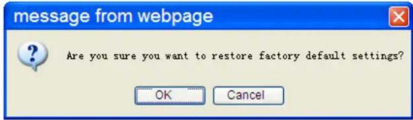
text_image
message from webpage Are you sure you want to restore factory default settings? OK CancelNote:
Broadband Router Restore
The Broadband Router configuration has been restored to default settings and the router is rebooting.
Close the Broadband Router Configuration window and wait for 2 minutes before reopening your web browser. If necessary, reconfigure your PC's IP address to match your new configuration.
System Log
To let users view or configure System Log.
System Log
The System Log dialog allows you to view the System Log and configure the System Log options.
Click "View System Log" to view the System Log.
Click "Configure System Log" to configure the System Log options.
View System Log
Configure System Log
Click to configure the log.
Log:

Disable Enable
Log Level:
Display Level:
Mode:
Informational
Informational
Local
Apply/Save
Log: enable or disable this function.
Log level: select your log level. The log level allows you to configure which types of events are logged. For the Log level, all the events above or equal to the selected level will be logged. There are eight log levels from high to low are displayed below:
① Emergency = system is unusable
① Alert = action must be taken immediately
① Critical = critical conditions
(i) Error = error conditions
① Warning = warning conditions
① Notice = normal but significant conditions
① Informational = information events
① Debugging = debug-level messages
The gateway records all log events at the chosen level and above. For instance, if you set the log level to Critical, all critical, alert, and emergency events are logged, but none of the others are recorded
Display Level: display the log according to the level you set when you view system log. For the Display level, all the events above or equal to the selected level will be displayed. Once you set the display level, the logs of the same or higher priority will be displayed.
Mode: select the mode to determine where to record. Three modes: local, Remote and Both. Default is set to Local.
① Local: select this mode to store the logs in the router's local memory.
(i) Remote: select this mode to send the log information to a remote log server. Then you must assign the remote log server and port, 514 is often used.
① Both: logs stored adopting above two ways.
Click Apply/Save to save your settings.
After finishing the system log configuration, the log will be performed as set, you can click to see the System log of this router. The logs will be listed as configured above.
Click refresh to get the latest information.
System Log
| Date/Time | Facility | Severity | Message |
| Jan 100:00:12 | user | warn | kernel: 0: 0x00000000 -> 0x00001f00 |
| Jan 100:00:12 | user | warn | kernel: Built 1 zonelists in Zone order, mobility grouping on. Total pages: 7874 |
| Jan 100:00:12 | user | notice | kernel: Kernel command line: root=31:0 ro noinitrd console=ttyS0,115200 |
| Jan 100:00:12 | user | warn | kernel: wait instruction: enabled |
| Jan 100:00:31 | user | warn | kernel: bcmxtmcfg: Connection UP, LinkActiveStatus=0x1, US=1024000, DS=8000000 |
Refresh
Close
SNMP Agent
SNMP, Simple Network Management Protocol, is the most popular one in network. It consists of SNMP Manager, SNMP Agent and MIB. Every network device supporting SNMP will have a SNMP Agent which is a management software running in the device.
SNMP Manager, the management software running the server, is to use SNMP protocol to send GetRequest、GetNextRequest, SetRequest message to Agent to view and change the information of the device.
SNMP Agents, the management software running in the device, accepts the message from the manager, Reads or Writes the management variable in MIB accordingly and then generates Response message to send it to the manager. Also, agent will send Trap message to the manager when agent finds some exceptions.
Trap message, is the message automatically sent by the managed device without request to the manager about the emergency events.
SNMP - Configuration
Simple Network Management Protocol (SNMP) allows a management application to retrieve statistics and status from the SNMP agent in this device.
Select the desired values and click "Apply" to configure the SNMP options.
SNMP Agent ☑ Disable ☐ Enable
| Read Community: | public |
| Set Community: | private |
| System Name: | home.gateway |
| System Location: | unknown |
| System Contact: | unknown |
| Trap Manager IP: | 0.0.0.0 |
Save/Apply
SNMP Agent: enable or disable SNMP Agent.
Read Community: Type the Get Community, which is the authentication for the incoming Get-and GetNext requests from the management station.
Set Community: Type the Set Community, which is the authentication for incoming Set requests from the management station.
System Name: here it refers to your router.
System Location: user-defined location.
System Contact: user-defined contact message.
Trap manager IP: enter the IP address of the server receiving the trap sent by SNMP agent.
TR-069 Client
TR-069 (short for Technical Report 069) is a DSL Forum (which was later renamed as Broadband Forum) technical specification entitled CPE WAN Management Protocol (CWMP). It defines an application layer protocol for remote management of end-user devices. It defines an application layer protocol for remote management of end-user devices.
As a bidirectional SOAP/HTTP based protocol it can provides the communication between customer premises equipment (CPE) and Auto Configuration Server (ACS). It includes both a safe configuration and the control of other CPE management functions within an integrated framework. In the course of the booming broadband market, the number of different internet access possibilities grew as well (e.g. modems, routers, gateways, set-top box, VoIP-phones). At the same time the configuration of this equipment became more complicated –too complicated for end-users. For this reason, TR-069 was developed. It provides the possibility of auto configuration of the access types. Using TR-069 the terminals can get in contact with the Auto Configuration Servers (ACS) and establish the configuration automatically and let ACS configure CPE automatically.
TR-069 client - Configuration
WAN Management Protocol (TR-069) allows a Auto-Configuration Server (ACS) to perform auto-configuration, provision, collection, and diagnostics to this device.
Select the desired values and click "Apply/Save" to configure the TR-069 client options.
Inform
Disable Enable
Inform Interval:
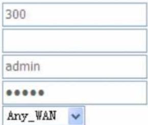
text_image
300 admin Any_WANACS URL:
ACS User Name:
ACS Password:
WAN Interface used by TR-069 client:
Any_WAN
Display SOAP messages on serial console
Disable Enable
√ Connection Request Authentication
Connection Request User Name:
Connection Request Password:
Connection Request URL:

Inform: select enable to let CPE be authorized to send Inform message to automatically connect to ACS.
Inform Interval: Specify the inform interval time (sec) which CPE used to periodically send inform message to automatically connect to ACS. When the inform interval time arrives, the CPE will send inform message to automatically connect to ACS.
ACS URL: Enter the ACS server login name.
ACS User Name: Specify the ACS User Name for ACS authentication to the connection from CPE.
ACS password: Enter the ACS server login password.
WAN interface used by TR-069: select the interface used by TR-069.
Display SOAP message on serial console: select whether to display SOAP message on serial console.
Connection Request Authentication: Check to enable connection request authentication feature. Connection Request User Name: Enter the username for ACS server to make connection request.
Connection Request User Password: Enter the password for ACS server to make connection request.
GetRPCMethods: supported by both CPE and ACS, display the supported RFC listing methods.
Click Apply/Save to apply your settings.
Internet Time
The router does not have a real time clock on board; instead, it uses the Network Time Protocol (NTP) to get the most current time from an NTP server.
NTP is a protocol for synchronization of computers. It can enable computers synchronize to the NTP server or clock source with a high accuracy.
Time settings
This page allows you to the modem's time configuration.
√ Automatically synchronize with Internet time servers
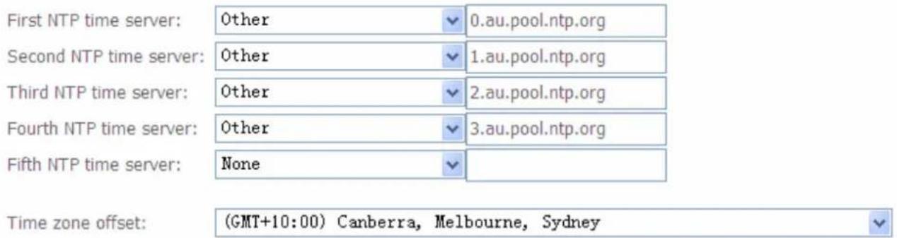
text_image
First NTP time server: Other 0.au.pool.ntp.org Second NTP time server: Other 1.au.pool.ntp.org Third NTP time server: Other 2.au.pool.ntp.org Fourth NTP time server: Other 3.au.pool.ntp.org Fifth NTP time server: None Time zone offset: (GMT+10:00) Canberra, Melbourne, SydneyApply/Save
Choose the NTP time server from the drop-down menu, If you prefer to specify an NTP server other than those in the drop-down list, simply enter its IP address in their appropriate blanks provided as shown above. Your ISP may also provide an SNTP server for you to use.
Choose your local time zone from the drop-down menu. After a successful connection to the Internet, the router will retrieve the correct local time from the NTP server you have specified. If you prefer to specify an NTP server other than those in the drop-down list, simply enter its IP address in their appropriate blanks provided as shown above. Your ISP may also provide an NTP server for you to use.
Click Apply/Save to apply your settings.
Access Control
Passwords
Passwords are used to prevent unauthorized access to the router configuration page.
Access to your broadband router is controlled through three user accounts: admin, support, and user.
The user name "admin" has unrestricted access to change and view configuration of your Broadband Router.
The user name "support" is used to allow an ISP technician to access your Broadband Router for maintenance and to run diagnostics.
The user name "user" can access the Broadband Router, view configuration settings and statistics, as well as, update the router's software.
Log in with the appropriate account and the corresponding authorized sections will be displayed for access.
Access Control -- Passwords
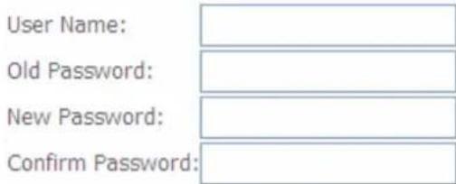
text_image
User Name: Old Password: New Password: Confirm Password:
Username: the default username for each user level.
Old Password: Enter the old password.
New Password: Enter the new password.
Confirm Password: Enter again the new password to confirm.
Click Apply to apply your new settings.
Services
Here lists some services, you can determine whether to enable one or all for access. For example, if you enable Telnet service, then you can have telnet session with your router, or if you enable HTTP service of both LAN and WAN side, you can access your router through both LAN and WAN with your web browser.
Access Control -- Services
A Service Control List ("SCL") enables or disables services from being used.
| Services | LAN | WAN |
| FTP | Enable | Enable |
| HTTP | Enable | Enable |
| ICMP | Enable | Enable |
| SNMP | Enable | Enable |
| SSH | Enable | Enable |
| TELNET | Enable | Enable |
| TFTP | Enable | Enable |
Save/Apply
Check the Enable checkbox to the service you want to enable.
You can also enable the specific service for LAN access or WAN access. For example, if you enable TELNET service both in WAN and LAN side, then you can have telnet sessions through both LAN and WAN.
Update Software
Software upgrading lets you experience the new and integral function of your router.
Tools -- Update Software
Step 1: Obtain an updated software image file from your ISP.
Step 2: Enter the path to the image file location in the box below or click the "Browse" button to locate the image file.
Step 3: Click the "Update Software" button once to upload the new image file.
NOTE: The update process takes about 2 minutes to complete, and your DSL Router will reboot.
Software File Name: Browse...
Update Software
Your router's "firmware" is the software that allows it to operate and provides all its functionality.
Think of your router as a dedicated computer, and the firmware as the software it runs. Over time this software may be improved and revised, and your router allows you to upgrade the software it runs to take advantage of these changes.
Clicking on Browse will allow you to select the new firmware image file you have downloaded to your PC. Once the correct file is selected, click Upgrade Software to update the firmware in your router. You will see the update in progress widow. Wait about 2 minutes for the router to update software. If necessary, reconfigure your PC's IP, then open your web browser.
DSL Router Update
Uploading is in progress. The DSL Router will reboot upon completion. This process will take about 2 minutes.
Close the DSL Router configuration window and wait for 2 minutes before reopening you web browser. If necessary, reconfigure your PC's IP address to match your new configuration.
60%
Back

Warning
DO NOT power down the router or interrupt the firmware upgarding while it is still in process. Improper operation could damage the router.
Reboot
This feature is used to restart the router the current settings. Click the button Reboot to proceed. When you want to restart to Default Setting, please turn to Management > Settings > Restore Default.
Click the button below to reboot the router.
Reboot
Tools
In this page, you can ping or trace route. Only IP address can be ping or traced.
IP Address:

Input the IP address and Click Ping or Trace Route button.
For example, Ping Google Public DNS (8.8.8.8).
IP Address:
8.8.8.8

Click Ping button, then you can see the result as follows if the route is up.
PING 8.8.8.8 (8.8.8.8): 56 data bytes
56 bytes from 8.8.8.8: icmp_seq=0 ttl=49 time=73.0 ms
56 bytes from 8.8.8.8: icmp_seq=1 ttl=49 time=70.7 ms
56 bytes from 8.8.8.8: icmp_seq=2 ttl=49 time=71.0 ms
56 bytes from 8.8.8.8: icmp_seq=3 ttl=49 time=72.5 ms

--- 8.8.8.8 ping statistics ---
4 packets transmitted, 4 packets received, 0% packet loss
round-trip min/avg/max = 70.7/71.8/73.0 ms
Ping Result
Return
Chapter 5: Troubleshooting
If your router is not functioning properly, please refer to the suggested solutions provided in this chapter. If your problems persist or the suggested solutions do not meet your needs, please kindly contact your service provider or Billion for support.
Problems with the router
| Problem | Suggested Action |
| None of the LEDs is on when you turn on the router | Check the connection between the router and the adapter. If the problem persists, most likely it is due to the malfunction of your hardware. Please contact your service provider or Billion for technical support. |
| You have forgotten your login username or password | Try the default username "admin" and password "admin". If this fails, you can restore your router to its factory settings by pressing the reset button on the device rear side. |
Problems with WAN interface
| Problem | Suggested Action |
| Frequent loss of ADSL line sync (disconnections) | Ensure that all other devices connected to the same telephone line as your router (e.g. telephones, fax machines, analogue modems) have a line filter connected between them and the wall socket (unless you are using a Central Splitter or Central Filter installed by a qualified and licensed electrician), and ensure that all line filters are correctly installed and the right way around. Missing line filters or line filters installed the wrong way around can cause problems with your ADSL connection, including causing frequent disconnections. If you have a back-to-base alarm system you should contact your security provider for a technician to make any necessary changes. |
Problem with LAN interface
| Problem | Suggested Action |
| Cannot PING any PC on LAN | Check the Ethernet LEDs on the front panel.The LED should be on for the port that has a PC connected. If it does not lit, check to see if the cable between your router and the PC is properly connected. Make sure you have first uninstalled your firewall program before troubleshooting. |
| Verify that the IP address and the subnet mask are consistent for both the router and the workstations. |
Appendix: Product Support & Contact
If you come across any problems please contact the dealer from where you purchased your product.
Contact Billion
Worldwide:
http://www.billion.com
MAC OS is a registered Trademark of Apple Computer, Inc.
Windows 7/98, Windows NT, Windows 2000, Windows Me, Windows XP and Windows Vista are registered Trademarks of Microsoft Corporation.