
750Li xDrive (2015) - Automotive BMW - Free user manual and instructions
Find the device manual for free 750Li xDrive (2015) BMW in PDF.


User questions about 750Li xDrive (2015) BMW
0 question about this device. Answer the ones you know or ask your own.
Ask a new question about this device
Download the instructions for your Automotive in PDF format for free! Find your manual 750Li xDrive (2015) - BMW and take your electronic device back in hand. On this page are published all the documents necessary for the use of your device. 750Li xDrive (2015) by BMW.
USER MANUAL 750Li xDrive (2015) BMW
text_image
Contents A-Z Owner's Manual for Vehicle BMW The Ultimate Driving Machine® M CV 1154THE BMW 7 SERIES.
OWNER'S MANUAL.
BMW EfficientDynamics
Less emissions. More driving pleasure.
7 Series Owner's Manual for Vehicle
Thank you for choosing a BMW.
The more familiar you are with your vehicle, the better control you will have on the road. We therefore strongly suggest:
Read this Owner's Manual before starting off in your new BMW. Also use the Integrated Owner's Manual in your vehicle. It contains important information on vehicle operation that will help you make full use of the technical features available in your BMW. The manual also contains information designed to enhance operating reliability and road safety, and to contribute to maintaining the value of your BMW.
Any updates made after the editorial deadline can be found in the appendix of the printed Owner's Handbook for Vehicle.
Supplementary information can be found in the additional brochures in the onboard literature.
We wish you a safe and enjoyable ride
BMW AG
The Owner's Manual is available in many countries as an app.
Additional information on the Internet:
www.bmw.com/bmw_drivers_guide
Reprinting, including excerpts, only with the written consent of BMW AG, Munich.
US English VI/15, 07 15 490
Printed on environmentally friendly paper, bleached without chlorine, suitable for recycling.
Contents
The fastest way to find information on a particular topic or item is by using the index, refer to page 302.
6 Information
At a glance
14 Cockpit
19 Idle state, operating and drive readiness
21 iDrive
30 BMW gesture control
33 Voice activation system
36 BMW Touch Command
38 General settings
49 Integrated Owner's Manual in the vehicle
Controls
54 Opening and closing
76 Adjusting
93 Transporting children safely
97 Driving
113 Displays
129 Lights
136 Safety
163 Driving stability control systems
168 Driver assistance systems
200 Driving comfort
203 Climate control
215 Interior equipment
225 Storage compartments
Driving tips
234 Things to remember when driving
237 Loading
240 Saving fuel
Mobility
250 Refueling
252 Fuel
254 Wheels and tires
271 Engine compartment
273 Engine oil
277 Coolant
279 Maintenance
281 Replacing components
286 Breakdown assistance
291 Care
Reference
298 Technical data
301 Appendix
302 Everything from A to Z
Information
Using this Owner's Manual
Orientation
The fastest way to find information on a particular topic is by using the index.
An initial overview of the vehicle is provided in the first chapter.
Updates made after the editorial deadline
Any updates made after the editorial deadline can be found in the appendix of the printed Owner's Handbook for Vehicle.
User's manual for Navigation, Entertainment, Communication
The Owner's Manual for Navigation, Entertainment, and Communication is available as printed book at your service center.
The topics of Navigation, Entertainment, and Communication can be retrieved on the Control Display via the Integrated Owner's Manual and in the BMW Driver's Guide app.
Additional sources of information
A dealer's service center or another qualified service center or repair shop will be glad to answer additional questions at any time.
Information on BMW, e.g., on technology, is available on the Internet: www.bmwusa.com.
BMW Driver's Guide App
The Owner's Manual is available in many countries as an app. Additional information on the Internet:
www.bmw.com/bmw_drivers_guide
Symbols and displays
Symbols in the Owner's Manual
A Indicates precautions that must be followed precisely in order to avoid the possibility of personal injury and serious damage to the vehicle.
Marks the end of a specific item of information.
Refers to measures that can be taken to help protect the environment.
"..." Identifies display texts in vehicle used to select individual functions.
»...« Verbal instructions to use with the voice activation system.
»...« Identifies the answers generated by the voice activation system.
Action steps
Action steps to be carried out are presented as numbered list. The steps must be carried out in the defined order.
-
First action step.
-
Second action step.
Enumerations
Enumerations without mandatory order or alternative possibilities are presented as list with bullet points.
▶ First possibility.
▶ Second possibility.
Symbols on vehicle components
i Indicates that you should consult the relevant section of this Owner's Manual for information on a particular part or assembly.
Vehicle features and options
This Owner's Manual describes all models and all standard, country-specific and optional equipment that is offered in the model series. Therefore, in this Owner's Manual, we also describe and illustrate features that are not available in your vehicle, e.g., because of the selected optional features or the country-specific version.
This also applies to safety-related functions and systems.
The respectively applicable country provisions must be observed when using the respective features and systems.
For any options and equipment not described in this Owner's Handbook, refer to the Supplementary Owner's Handbooks.
On right-hand drive vehicles, some controls are arranged differently from what is shown in the illustrations.
Status of the Owner's Manual
Basic information
The manufacturer of your vehicle pursues a policy of constant development that is conceived to ensure that our vehicles continue to embody the highest quality and safety standards. In rare cases, therefore, the features described in this Owner's Manual may differ from those in your vehicle.
Updates made after the editorial deadline
Any updates made after the editorial deadline can be found in the appendix of the printed Owner's Handbook for Vehicle.
Own safety
Warranty
Your vehicle is technically configured for the operating conditions and registration requirements applying in the country of first delivery also known as homologation. If your vehicle is to be operated in a different country it might be necessary to adapt your vehicle to potentially differing operating conditions and permit requirements. If your vehicle does not comply with the homologation requirements in a certain country you may not be able to lodge warranty claims for your vehicle there. Further information on warranty is available from a dealer's service center.
Maintenance and repairs
Advanced technology, e.g., the use of modern materials and high-performance electronics, requires suitable maintenance and repair work.
The manufacturer of the vehicle recommends that you entrust corresponding procedures to a BMW dealer's service center. If you choose to use another service facility, BMW recommends use of a facility that performs work, e.g. maintenance and repair, according to BMW specifications with properly trained personnel, referred to in this Owner's Manual as "another qualified service center or repair shop".
If work is performed improperly, e.g. maintenance and repair, there is a risk of subsequent damage and related safety risks.
Parts and accessories
BMW recommends the use of parts and accessory products approved by BMW.
Approved parts and accessories, and advice on their use and installation are available from a BMW dealer's service center.
BMW parts and accessories were tested by BMW for their safety and suitability in BMW vehicles.
BMW warrants genuine BMW parts and accessories.
BMW does not evaluate whether each individual product from another manufacturer can be used with BMW vehicles without presenting a safety hazard, even if a country-specific official approval was issued. BMW does not evaluate whether these products are suitable for BMW vehicles under all usage conditions.
California Proposition 65 Warning
California laws require us to state the following warning:
Engine exhaust and a wide variety of automobile components and parts, including components found in the interior furnishings in a vehicle, contain or emit chemicals known to the State of California to cause cancer and birth defects and reproductive harm. In addition, certain fluids contained in vehicles and certain products of component wear contain or emit chemicals known to the State of California to cause cancer and birth defects or other reproductive harm. Battery posts, terminals and related accessories contain lead and lead compounds. Wash your hands after handling. Used engine oil contains chemicals that have caused cancer in laboratory animals. Always protect your skin by washing thoroughly with soap and water.
Service and warranty
We recommend that you read this publication thoroughly. Your vehicle is covered by the following warranties:
▶ New Vehicle Limited Warranty.
▶ Rust Perforation Limited Warranty.
▶ Federal Emissions System Defect Warranty.
▶ Federal Emissions Performance Warranty.
▶ California Emission Control System Limited Warranty.
Detailed information about these warranties is listed in the Service and Warranty Information
Booklet for US models or in the Warranty and Service Guide Booklet for Canadian models.
Your vehicle has been specifically adapted and designed to meet the particular operating conditions and homologation requirements in your country and continental region in order to deliver the full driving pleasure while the vehicle is operated under those conditions. If you wish to operate your vehicle in another country or region, you may be required to adapt your vehicle to meet different prevailing operating conditions and homologation requirements. You should also be aware of any applicable warranty limitations or exclusions for such country or region. In such case, please contact Customer Relations for further information.
Maintenance
Maintain the vehicle regularly to sustain the road safety, operational reliability and the New Vehicle Limited Warranty.
Specifications for required maintenance measures:
▶ BMW Maintenance system
▶ Service and Warranty Information Booklet for US models
▶ Warranty and Service Guide Booklet for Canadian models
If the vehicle is not maintained according to these specifications, this could result in serious damage to the vehicle. Such damage is not covered by the BMW New Vehicle Limited Warranty.
Data memory
Many electronic components on your vehicle are equipped with data memories that temporarily or permanently store technical information about the condition of the vehicle, events and faults. This technical information generally records the state of a component, a module, a system or the environment:
▶ Operating mode of system components, fill levels for instance.
▶ Status messages for the vehicle and from its individual components, e.g., wheel rotation speed/vehicle speed, deceleration, transverse acceleration.
▶ Malfunctions and faults in important system components, e.g., lights and brakes.
▶ Responses by the vehicle to special situations such as airbag deployment or engaging the stability control system.
Ambient conditions, such as temperature. This data is purely technical in nature and is used to detect and correct faults and to optimize vehicle functions. Motion profiles over routes traveled cannot be created from this data. When service offerings are used, e.g., repair services, service processes, warranty claims, quality assurance, this technical information can be read out from the event and fault memories by employees of the dealer's service center or another qualified service center or repair shop, including the manufacturer, using special diagnostic tools. You can obtain further information there if you need it. After an error is corrected, the information in the fault memory is deleted or overwritten on a continuous basis.
With the vehicle in use there are situations where you can associate these technical data with individuals if combined with other information, e.g., an accident report, damage to the vehicle, eye witness accounts — possibly with the assistance of an expert.
Additional functions that are contractually agreed with the customer - such as vehicle emergency locating - you can transmit certain vehicle data from the vehicle.
Event Data Recorder EDR
This vehicle is equipped with an event data recorder EDR. The main purpose of an EDR is to record, in certain crash or near crash-like situations, such as an air bag deployment or hitting a road obstacle, data that will assist in understanding how a vehicle's systems performed. The EDR is designed to record data related to vehicle dynamics and safety systems for a short period of time, typically 30 seconds or less.
The EDR in this vehicle is designed to record such data as:
▶ How various systems in your vehicle were operating.
▶ Whether or not the driver and passenger safety belts were fastened.
▶ How far, if at all, the driver was depressing the accelerator and/or brake pedal.
▶ How fast the vehicle was traveling.
These data can help provide a better understanding of the circumstances in which crashes and injuries occur.
EDR data are recorded by your vehicle only if a nontrivial crash situation occurs; no data are recorded by the EDR under normal driving conditions and no personal data, e.g., name, gender, age, and crash location, are recorded.
However, other parties, such as law enforcement, could combine the EDR data with the type of personally identifying data routinely acquired during a crash investigation.
To read data recorded by an EDR, special equipment is required, and access to the vehicle or the EDR is needed. In addition to the vehicle manufacturer, other parties, such as law enforcement, that have the special equipment, can read the information if they have access to the vehicle or the EDR.
Vehicle identification number
natural_image
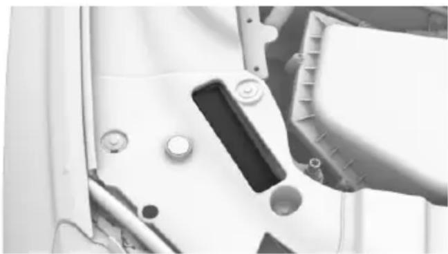
Close-up of a mechanical component with bolts and a central slot (no visible text or symbols)The vehicle identification number can be found in the engine compartment.
The vehicle identification number can also be found behind the windshield.
Reporting safety defects
For US customers
The following only applies to vehicles owned and operated in the US.
If you believe that your vehicle has a defect which could cause a crash or could cause injury or death, you should immediately inform the National Highway Traffic Safety Administration NHTSA, in addition to notifying BMW of North America, LLC, P.O. Box 1227, Westwood, New Jersey 07675-1227, Telephone 1-800-831-1117.
If NHTSA receives similar complaints, it may open an investigation, and if it finds that a safety defect exists in a group of vehicles, it may order a recall and remedy campaign.
However, NHTSA cannot become involved in individual problems between you, your dealer, or BMW of North America, LLC.
To contact NHTSA, you may call the Vehicle Safety Hotline toll-free at 1-888-327-4236 (TTY: 1-800-424-9153); go to http://www.safercar.gov; or write to: Administrator, NHTSA, 400 Seventh Street, SW., Washington, DC 20590. You can also obtain other in-
formation about motor vehicle safety from http://www.safercar.gov.
For Canadian customers
Canadian customers who wish to report a safety-related defect to Transport Canada, Defect Investigations and Recalls, may call the toll-free hotline 1-800-333-0510. You can also obtain other information about motor vehicle safety from http://www.tc.gc.ca/roadsafety.
text_image
Online Edition for Part no. 0140 2 964 330 - VI/15At a glance
These overviews of buttons, switches and displays are intended to familiarize you with your vehicle. You will also become quickly acquainted with the available control concepts and options.
Cockpit
Vehicle features and options
This chapter describes all standard, country-specific and optional features offered with the series. It also describes features that are not necessarily available in your car, e. g., due to
the selected options or country versions. This also applies to safety-related functions and systems. The respectively applicable country provisions must be observed when using the respective features and systems.
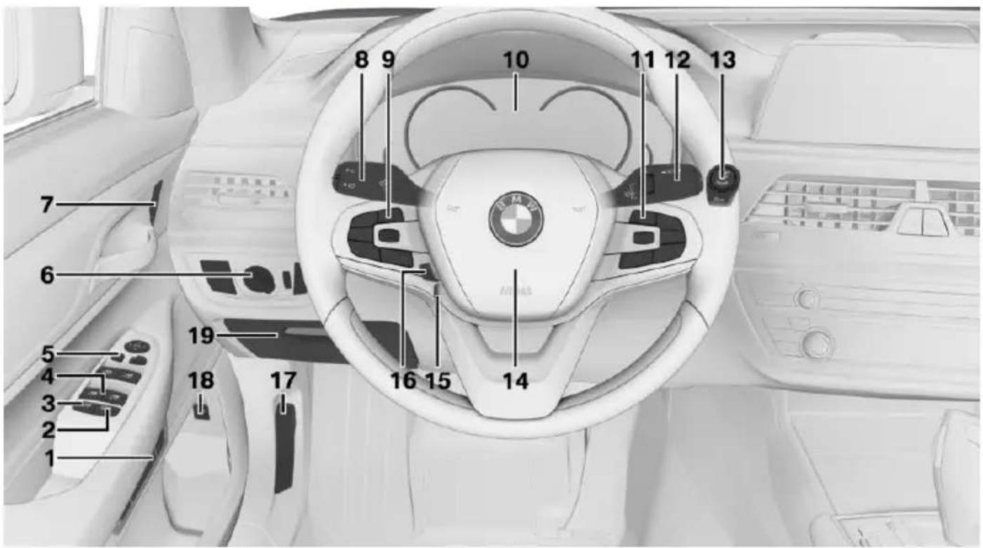
All around the steering wheel
text_image
8 9 10 11 12 13 7 6 5 4 3 2 1 19 18 17 16 15 141 Seating comfort features

Gentleman function 78

Seat, mirror, and steering wheel memory 87

Massage function 88
2 Roller sunblind in the rear window 72
3 Safety switch for the windows and roller sunblinds 71
4 Power windows 70
5 Exterior mirror operation 85
6 Lights

Front fog lights 132

Night Vision 147

Lights off
Automatic headlight control 130
Daytime running lights 131

Parking lights 129

Automatic headlight control 130
Adaptive Light Control 131
High-beam Assistant 132

Low beams 129

Instrument lighting 133

Right roadside parking
lamp 130

Left roadside parking lamp 130
7 Central locking system

Unlocking 63

Lock 63
8 Steering column stalk, left

Turn signal 103

High beams, head-
light flasher 103

High-beam Assistant 132

On-board computer 122
9 Steering wheel buttons, left

Cruise control on/off 175

Active Cruise Control on/off 168

Resume speed 175, 168,

Pause or continue cruise control 175, 168

Increase distance 168

Reduce distance 168

With steering and lane guidance assistant: adjust speed 168

Steering and lane control assis- tant on/off 177
Cruise control rocker switch 175, 168,
10 Instrument cluster 113
11 Steering wheel buttons, right

Entertainment source

Volume

Voice activation system 33

Telephone
Thumbwheel for selection lists 121
12 Steering column stalk, right

Wiper 103

Rain sensor 104

Cleaning the windshield and headlights 105
13 Start/stop engine 97

Auto Start/Stop function 98
14 Horn
15 Steering wheel heating 87

16 Adjust steering wheel 87

17 Unlock hood 272
18 Open/close trunk lid 64

19 Glove compartment 226
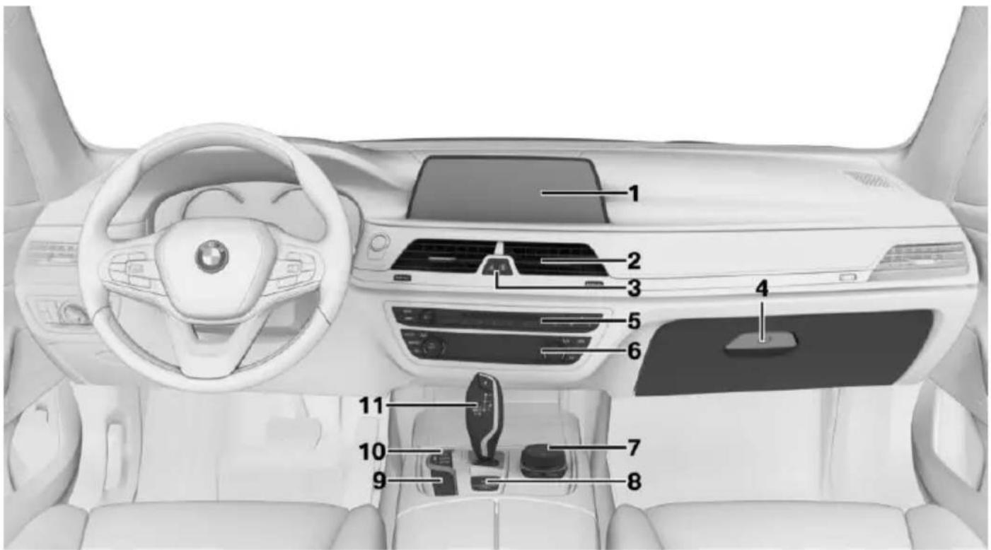
All around the center console
text_image
Top-down view of a car interior with numbered labels pointing to various dashboard and steering areas.1 Control Display 21
2 Fan 206
3 Hazard warning system 286


Intelligent Safety 139

NFC antenna 43
4 Glove compartment 225
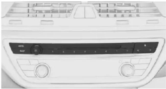
5 Radio
Multimedia
6 Automatic climate control 203
7 Controller with buttons 22
8 Parking brake 100


Automatic Hold 101
9 PDC Park Distance Control 180

Without Surround View: rearview
camera 184
Surround View 187
Cross traffic warning 197
Parking assistant 193
Surround View: Panorama
View 187

HDC Hill Descent Control 165

Air suspension 200
10 Driving Dynamics Control 110


DSC Dynamic Stability Control 163
11 Steptronic transmission selector lever 106
All around the roofliner
text_image
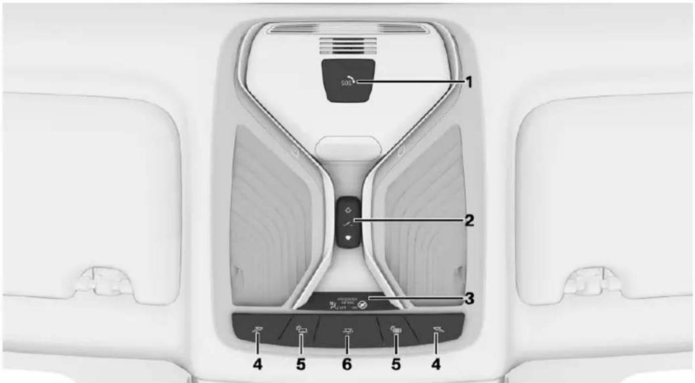
1 2 3 4 5 6 5 41 Intelligent Emergency Request 286
2 Glass sunroof 73
3 Indicator lamp, front-seat passenger airbag 138
4 Reading lights 133
5 Open rear sliding visor 74

Close rear sliding visor 74
6 Interior lights 133
Idle state, operating and drive readiness
Vehicle features and options
This chapter describes all standard, country-specific and optional features offered with the series. It also describes features that are not necessarily available in your car, e.g., due to the selected options or country versions. This also applies to safety-related functions and systems. The respectively applicable country provisions must be observed when using the respective features and systems.
General information
Depending on the situation, the vehicle is in one of the three states:
▶ Idle state.
▶ Operating readiness.
▶ Drive readiness.
Idle state
The concept
The vehicle is switched off in idle state. All electronic systems/power consumers are deactivated.
General information
The vehicle is in idle state prior to opening from the outside and after exiting and locking.
Information

WARNING
An unsecured vehicle can put itself into motion and roll away. There is risk of an accident. Before exiting, secure the vehicle against rolling.
In order to ensure that the vehicle is secured against rolling away, observe the following:
▷ Set the parking brake.
On uphill grades or on a slope, turn the front wheels in the direction of the curb.
On uphill grades or on a slope, also secure the vehicle, e.g. with a wheel chock.

WARNING
Unattended children or animals can move the vehicle and endanger themselves and traffic, e.g. with the following actions:
▶ Pressing the Start/Stop button.
▶ Releasing the parking brake.
▶ Opening and closing of doors or windows.
▶ Shifting the selector lever into neutral.
▶ Using vehicle equipment.
There is risk of accidents or injuries. Do not leave children or animals unattended in the vehicle. Carry remote control along when exiting and lock the vehicle.
Idle state automatic
The idle state is automatically established:
▶ After several minutes, if no operation takes place on the vehicle.
▶ If the charging state of the vehicle batteries is low.
▶ If one of the front doors is opened, depending on the setting via iDrive,
The idle state is not automatically established while a phone call is active.
Establishing idle state when opening the front doors
About iDrive:
- "My Vehicle"
- "Vehicle settings"
- "Doors/Key"
- "Turn off after door opening"
Idle state manual
Establish idle state in the vehicle after trip end:
natural_image
Front view of a white car air conditioner unit with control panel and fan (no visible text or symbols)
Hold button down until the OFF indicator on the instrument cluster goes out.
Operating readiness
The concept
When operating readiness is switched on, most functions can be used while the vehicle is stationary. Desired settings can be adjusted.
General information
The vehicle is in operating readiness state after opening via the front doors.
Display
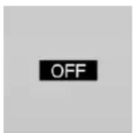
OFF is displayed in the instrument cluster. The drivetrain is switched off and operating readiness switched on.
Drive readiness
The concept
Activating drive readiness corresponds to switching on the engine.
Information
Some functions, such as DSC, can only be used in drive readiness state. Observe further hints regarding drive readiness, refer to page 97.
Activating drive readiness
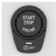
Drive readiness is switched on via the Start/Stop button:
- Depress the brake pedal.
- Press the Start/Stop button.
Display

READY is displayed in the instrument cluster.
Switch off drive readiness
Press the Start/Stop button to switch off the drive readiness. The vehicle switches into operating readiness state.
iDrive
Vehicle features and options
This chapter describes all standard, country-specific and optional features offered with the series. It also describes features that are not necessarily available in your car, e.g., due to the selected options or country versions. This also applies to safety-related functions and systems. The respectively applicable country provisions must be observed when using the respective features and systems.
The concept
The iDrive combines the functions of many switches. These functions can be operated via controller or touchscreen.
Information

WARNING
Operating the integrated information system and communication devices while driving can distract from traffic. It is possible to lose control of the vehicle. There is risk of an accident. Only use the systems or devices when the traffic situation allows. If necessary stop and use the systems and devices while the vehicle is stationary.
Control elements
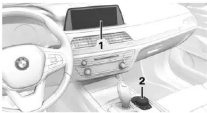
Overview
natural_image
Interior view of a car dashboard and steering wheel, showing key components (no text or symbols visible)1 Control Display with touchscreen
2 Controller with buttons and touchpad
Control Display
Information
To clean the Control Display, follow the care instructions, refer to page 294.
Do not place objects close to the Control Display; otherwise, the Control Display can be damaged.
In the case of very high temperatures on the Control Display, e.g. due to intense solar radiation, the brightness may be reduced down to complete deactivation. Once the temperature is reduced, e.g. through shadow or climate control system, the normal functions are re-established.
Switching on
- Turn on operations.
- Press the controller.
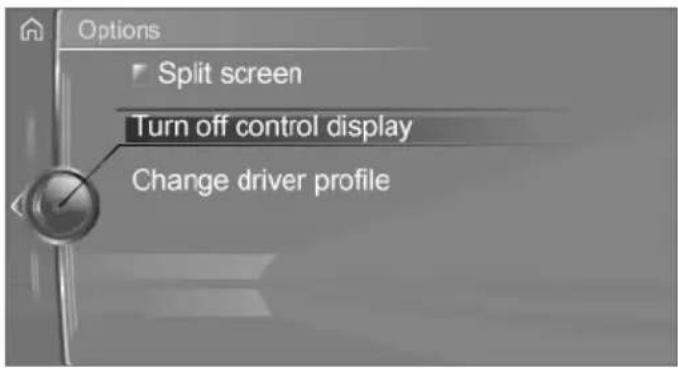
Switch off

2. "Turn off control display"
text_image
Options Split screen Turn off control display Change driver profileController
General information
The buttons can be used to open the menus directly. The controller can be used to select menu items and enter the settings.
Some iDrive functions can be operated using the touchpad on the controller, refer to page 26.
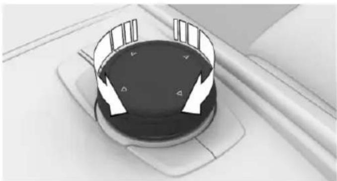
▷ Turn.
natural_image
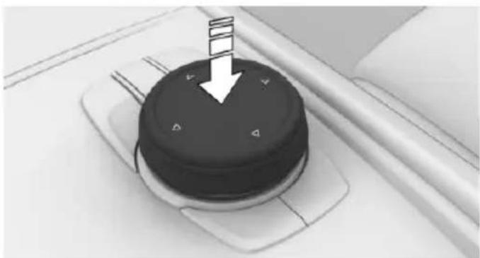
Top-down view of a rotary knob with directional arrows indicating rotation (no text or symbols)▷ Press.
natural_image
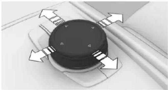
Close-up of a black circular device with control buttons and a white arrow pointing downward (no text or symbols visible)▶ Move in four directions.
natural_image
Close-up of a mechanical component with directional arrows indicating motion or force (no text or symbols)Buttons on controller
Press button Function
 | Press once: call up main menu. |
 | Press twice: open recently used menus. |
 | Open the Communication menu. |
 | Open the Media/Radio menu. |
 | Open destination input menu for navigation. |
 | Open navigation map. |
 | Open previous panel. |
 | Open Options menu. |
Operating with the controller
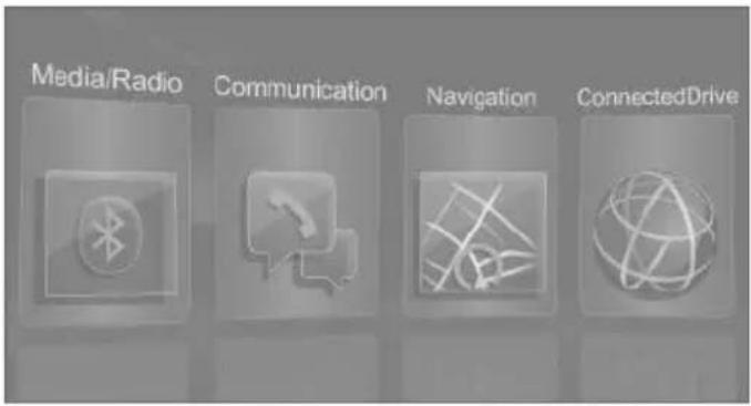
Opening the main menu

Press button.
text_image
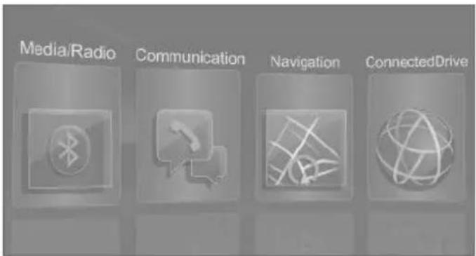
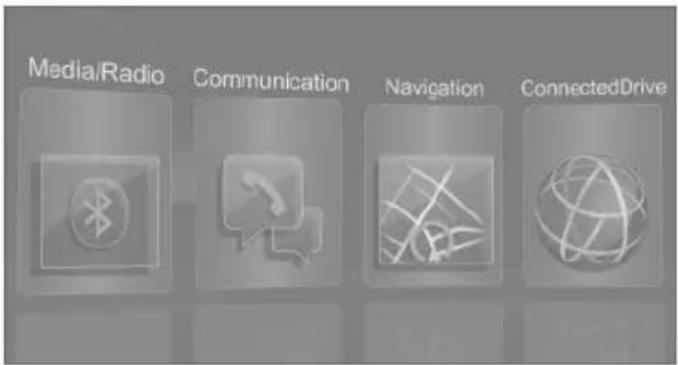
Media/Radio Communication Navigation ConnectedDriveThe main menu is displayed.
All iDrive functions can be called up via the main menu.
Selecting menu items
Highlighted menu items can be selected.
- Turn the controller until the desired menu item is highlighted.
text_image
Media/Radio Communication Navigation ConnectedDrive- Press the controller.
Menu items in the Owner's Manual
In the Owner's Manual, menu items that can be selected are set in quotation marks, e.g.
"System settings".
Changing between panels
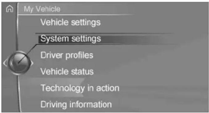
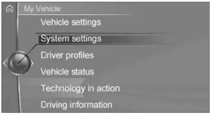
After a menu item is selected, e.g., "System settings", a new panel is displayed.
▶ Move the controller to the left.
Closes current display and shows previous display.
BACK Press button.
The previous display opens.
▶ Move the controller to the right. New display is opened.
text_image
My Vehicle Vehicle settings System settings Driver profiles Vehicle status Technology in action Driving informationWhite arrows pointing to the left or right indicate that additional panels can be opened.
Opening recently used menus
The recently used menus can be displayed.

Press button twice.
Opening Options menu

Press button.
The Options menu is displayed.
The Options menu consists of different areas:
▷ Screen settings, e.g., "Split screen".
▶ Control options for the selected main menu, e.g., for "Media/Radio".
▶ If applicable, further operating options for the selected menu, e.g., "Save station".
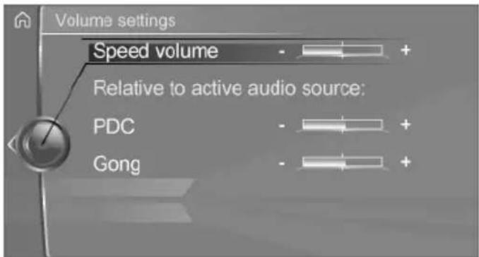
Changing settings
-
Select a field.
-
Turn the controller until the desired setting is displayed.
text_image
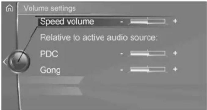
Volume settings Speed volume Relative to active audio source: PDC Gong- Press the controller.
Activating/deactivating the functions
Several menu items are preceded by a checkbox. The checkbox indicates whether the function is activated or deactivated. Selecting the menu item activates or deactivates the function.
Function is activated.
☐ Function is deactivated.
Entering letters and numbers
General information
Letters and numbers can be entered using the controller or the touchscreen.
The keyboard's display changes automatically.
Entry
-
Turn the controller: select letters or numbers.
-
: confirm entry.
Symbol Function
← Press the controller: delete the letter or number.
← Hold controller down: delete all letters and numbers.
Switching between cases, letters and numbers
Depending on the menu, you can switch between entering upper and lower case, letters and numbers.
Symbol Function
ABC Enter the letters.
1@+ Enter the numbers.
abc or ABC Change between capital and lower-case letters.
Entry comparison
When entering names and addresses, the choice is narrowed down with every letter entered and letters may be added automatically.
Entries are continuously compared with data stored in the vehicle.
▶ Only those letters are offered during input for which data is available.
Destination search: names of locations may be entered in languages available through iDrive.
Using alphabetical lists
For alphabetical lists with more than 30 entries, the letters for which there is an entry are displayed at the left edge.
-
Turn the controller to the left or right quickly.
All letters for which there are entries are displayed on the left side. -
Select the first letter of the desired entry.
The cursor jumps to the first entry of the selected letter.
Operating via touchscreen
General information
The Control Display is equipped with a touchscreen.
Touch touchscreen with your fingers. Do not use any objects.
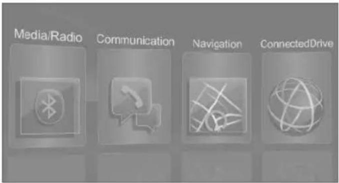
Opening the main menu
Tap symbol.
text_image
Media/Radio Communication Navigation ConnectedDriveAll iDrive functions can be called up via the main menu.
Selecting menu items
Tap desired menu item.
text_image
Media/Radio Communication Navigation ConnectedDriveMenu items in the Owner's Manual
In the Owner's Manual, menu items that can be selected are set in quotation marks, e.g. "System settings".
Changing between panels
After a menu item is selected, a new panel is displayed.
text_image
My Vehicle Vehicle settings System settings Driver profiles Vehicle status Technology in action Driving informationThe white arrow indicates that additional panels can be called up.
▷ Swipe to the left.
▷ Tap symbol.
New display is opened.
Opening recently used menus
Tap symbol twice.
Changing settings
Settings such as volumes can be changed via the touchscreen.
▶ Slide in the selected field to the right or left, until the desired setting is displayed.
▷ , - Tap symbol.
text_image
Volume settings Speed volume Relative to active audio source: PDC GongActivating/deactivating the functions
Several menu items are preceded by a checkbox. The checkbox indicates whether the function is activated or deactivated. Selecting the menu item activates or deactivates the function.
Function is activated.
☐ Function is deactivated.
Entering letters and numbers
General information
Letters and numbers can be entered using the controller or the touchscreen.
The keyboard's display changes automatically.
Symbol Function
← Tapping the symbol: delete the letter or number.
← Tapping the symbol for an extended period: delete all letters or numbers.
Switching between cases, letters and numbers
Symbol Function
ABC Enter the letters.
1@+ Enter the numbers.
ABC or abc Change between capital and lower-case letters.
Operating navigation map
The navigation map can be moved with the touchscreen.
Function Controls
Enlarge/shrink map. Drag in or out with the fingers.
Rotate map. Move fingers in a circle.
Touchpad
General information
Some iDrive functions can be operated using the touchpad on the controller.
Selecting functions
- "My Vehicle"
- "System settings"
- "Touchpad"
- Select desired setting.
▶ "Speller": enter letters and numbers.
▶ "Interactive map": viewing the interactive map.
▶ "Browser": enter Internet addresses.
▶ "Search fields": write letters without selecting the list field.
▶ "Audio feedback": pronounces entered letters and numbers.
▶ "Two-finger scrolling": operate lists.
Entering letters and numbers
Entering letters requires some practice at the beginning. When entering, pay attention to the following:
The system recognizes capital and lower case letters. For the input of upper/lower case letters and numbers, it may be necessary to switch to the corresponding input mode, e.g. when upper and lower case letters are written the same way. Switching between cases, numbers and letters, refer to page 24.
▶ Enter characters as they are displayed on the Control Display.
▶ Always enter associated characters, such as accents or periods so that the letter can be clearly recognized. Possible input depends on the set language. Where necessary, enter special characters via the controller.
To delete a character, swipe to the left on the touchpad.
To enter a blank space, slide to the right in the center of the touchpad.
To enter a hyphen, slide to the right in the upper area of the touchpad.
To enter an underscore, swipe to the right in the lower area of the touchpad.
Using interactive map and Internet
Via touch-pad move the interactive map in the navigation system and Internet sites.
Function Controls
| Move interactive map or Internet sites. | Swipe in the appropriate direction. |
| Enlarge/shrink interactive map or Internet sites. | Drag in or out on the touchpad with fingers. |
| Display the menu or open a link in the Internet. | Tap once. |
Changing settings
You may change control display settings via touchpad. Slide left or right accordingly.
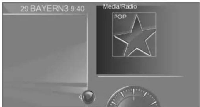
Split screen
General information
Additional information can be displayed on the right side of the split screen, e.g., information from the on-board compter.
In the divided screen view, the so-called split screen, this information remains visible even when you change to another menu.
Switching the split screen on and off
-
Press button.
-
"Split screen"
Selecting the display
-
Press button.
-
Move the controller to the right until the split screen is selected.
-
Press the controller.
text_image
29 BAYERN3 9:40 Media/Radio POP- Select desired setting.
Specifying the number of displays
It is possible to specify the number of displays.
- Move the controller to the right until the split screen is selected.
- Press the controller.
- "Personalize menu"
- Select desired setting.
- Move the controller to the left.
Status information
Status field
The following information is displayed in the status field:
▶ Messages.
▶ Wireless network reception strength.
▶ Current entertainment source.
Time.
Status field symbols
The symbols are grouped as follows.
Radio symbols
Symbol Meaning
HD Radio station is being received.
Telephone symbols
Symbol Meaning
Incoming or outgoing call.
Missed call.
... Wireless network reception strength.
Symbol flashes: network search.
Wireless network is not available.
Roaming is active.
☐ Text message was received.
Message received.
Reminder.
Sending not possible.
Contacts are imported.
Entertainment symbols
Symbol Meaning
CD/DVD player.
Music collection.
AUX-IN port.
AUX-IN port in the front or in the rear.
Bluetooth audio.
USB audio interface.
☐ Mobile phone audio interface.
Online Entertainment.
WLAN.
iPod.
Additional symbols
Symbol Meaning
⚠️ Check Control message.
Spoken instructions are turned off.
Request of the current vehicle position.
Programmable memory buttons
General information
The iDrive functions can be stored on the programmable memory buttons and called up directly, e.g., radio stations, navigation destinations, phone numbers and menu entries.
Settings are stored for the profile currently used.
Saving a function
- Select function via iDrive.
- 1...7 Press and hold the desired button until a signal sounds.
Running a function
1...7 Press button.
The function will work immediately. This means, e.g., that the number is dialed when a phone number is selected.
Displaying the button assignment
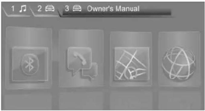
Touch buttons with bare fingers. Do not wear gloves or use objects.
The key assignment is displayed at top edge of screen.
text_image
1 2 3 Owner's ManualDeleting the button assignments
-
Press buttons 1 and 7 simultaneously for approx. five seconds.
-
"OK"
BMW gesture control
Vehicle features and options
This chapter describes all standard, country-specific and optional features offered with the series. It also describes features that are not necessarily available in your car, e. g., due to the selected options or country versions. This also applies to safety-related functions and systems. The respectively applicable country provisions must be observed when using the respective features and systems.
The concept
Several iDrive functions can be operated using BMW gesture control.
Overview
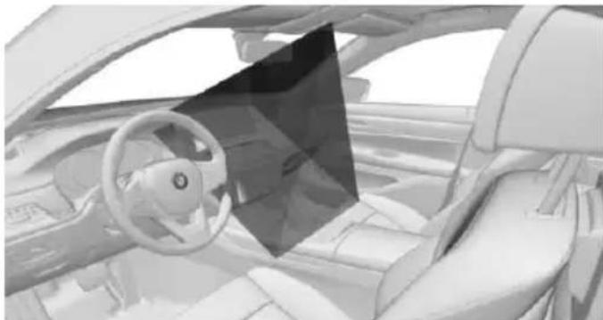
natural_image
Interior view of a modern car cockpit with steering wheel and dashboard (no visible text or symbols)The gestures are captured by a camera in the roofliner.
Perform gestures underneath the interior mirror.
Activation/deactivation
About iDrive:
- "My Vehicle"
- "System settings"
- "Gestures"
- "Gesture control"
Adjusting
▷ "Display tips": the possible gesture is shown on the Control Display.
▶ "Audio feedback": an acoustic signal is outputted once the gesture is recognized.
Possible gestures
Gesture Controls Function
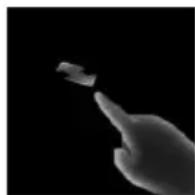
Move index finger forward and backward in the direction of the screen.
Accept call. Confirm Check Control message.
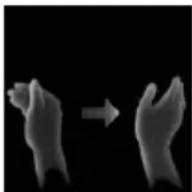
Swipe with the hand across the width of the Control Display in the direction of the front-passenger side.
Reject call. Close popup.
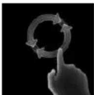
Slowly move forearm in a circular pattern with the index finger stretched out forward.
Increasing the vol- ume.
Gestures are detected after one circular motion.

Slowly move forearm in a circular pattern with the index finger stretched out forward.
Reducing the volume.
Gestures are detected after one circular motion.
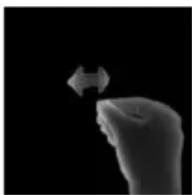
Pinch with thumb and index finger and move hand horizontally to the right or left.
Surround View: turn camera view.
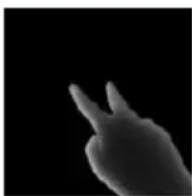
Move stretched out index and middle finger forward. Individually assignable gesture.
Execute gestures clearly.
The gestures can also be executed on the front-passenger side.
Assigning gesture individually
About iDrive:
- "My Vehicle"
- "System settings"
- "Gestures"
- "Function assignment"
- Select desired setting.
System limits
Gesture recognition by the camera can be disturbed by the following circumstances:
The camera objective is covered.
The camera objective is contaminated. Clean the camera lenses, refer to page 294.
The gesture is executed outside of the detection range.
The gesture can only be executed while the vehicle is stationary.
Voice activation system
Vehicle features and options
This chapter describes all standard, country-specific and optional features offered with the series. It also describes features that are not necessarily available in your car, e.g., due to the selected options or country versions. This also applies to safety-related functions and systems. The respectively applicable country provisions must be observed when using the respective features and systems.
The concept
▶ Most functions displayed on the Control Display can be operated by voice commands via the voice activation system. The system supports you with announcements during input.
▶ Functions that can only be used when the vehicle is stationary cannot be used via the voice activation system.
The system uses a special microphone on the driver's side.
▷ ... Verbal instructions in the Owner's Manual to use with the voice activation system.
Requirements
Via the Control Display, set a language that is also supported by the voice activation system so that the spoken commands can be identified.
Set the language, refer to page 38.
Using voice activation
Activating the voice activation system
- Press button on the steering wheel.
- Wait for the signal.
- Say the command.
A command that is recognized by the voice activation system is announced and displayed in the instrument cluster.

This symbol in the instrument cluster indicates that the voice activation system is active.
If no other commands are available, use function via iDrive.
Terminating the voice activation system

Briefly press the button on the steering wheel or >Cancel.
Possible commands
Most menu items on the Control Display can be voiced as commands.
Commends from other menus can also be spoken.
You may select lists such as phone lists via voice activation. Read these lists out loud exactly as they show in the respective list.
Displaying possible commands
Displayed in the top area of the Control Display are:
▷ Possible commands for the current menu.
▶ Possible commands from other menus.
▶ Status of the voice recognition.
▶ Status of the encrypted connection.
Help on the voice activation system
To have the available spoken instructions read out loud: »Voice commands«.
▶ Have information about the principle of operation for the voice activation system be announced: >General information on voice control.
▶ Announce help for the current menu: »Help«.
One example: open the tone settings
The commands of the menu items are spoken just as they are selected via the controller.
- Turn on the Entertainment sound output if needed.
Press button on the steering
- »Media and radio«
-
Tone
Adjusting
Setting the voice dialog
Set system to standard dialog or use a short version.
The short version of the voice dialog plays back short messages in abbreviated form.
About iDrive:
- "My Vehicle"
- "System settings"
- "Language"
- "Speech mode:"
- Select desired setting.
Selecting the input language
For some languages, the input language can be selected.
About iDrive:
- "My Vehicle"
- "System settings"
- "Language"
- "Voice control:"
- Select desired setting.
Activating encrypted connection
By activating an encrypted connection, the quality of voice recognition will be improved.
About iDrive:
- "My Vehicle"
- "System settings"
- "Language"
- "Speech recognition via server"
Encrypted connection active.
Adjusting the volume
Turn the volume button during the spoken instructions until the desired volume is set.
The volume remains constant even if the volume of other audio sources is changed.
The volume is stored for the drive profile currently used.
Information on Emergency Requests
Do not use the voice activation system to initiate an Emergency Request. In stressful situations, the voice and vocal pitch can change.
This can unnecessarily delay the establishment of a phone connection.
Instead, use the SOS button, refer to page 286, close to the interior mirror.
Environmental conditions
▷ Say the commands, numbers, and letters smoothly and with normal volume, emphasis, and speed.
▶ Always say commands in the language of the voice activation system.
▷ Keep the doors, windows, and glass sun-roof closed to prevent noise interference.
- Avoid making other noise in the vehicle while speaking.
BMW Touch Command
Vehicle features and options
This chapter describes all standard, country-specific and optional features offered with the series. It also describes features that are not necessarily available in your car, e.g., due to the selected options or country versions. This also applies to safety-related functions and systems. The respectively applicable country provisions must be observed when using the respective features and systems.
BMW Touch Command
The concept
Important functions of the vehicle can be used via BMW Touch Command.
▶ Seat adjustments for front passenger seat and seats in the rear.
▶ Climate control in the rear.
▶ Sun protection.
▶ Ambient light.
▶ Ambient light accent.
▶ Bowers & Wilkins loudspeaker lighting.
▶ Audio sources front.
▶ Rear entertainment.
▶ Some functions of the telephone in the rear.
General information
Depending on the vehicle's equipment, BMW Touch Command is located in the rear console or in the center armrest in the rear.
Control elements at a glance
Control elements
text_image
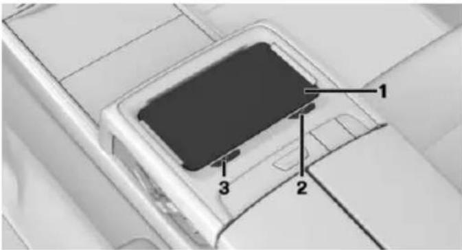
Technical diagram of a device with numbered components, likely for assembly or labeling reference.1 BMW Touch Command
2 Switching on/off
3 Removing
Tray
The tray in the center armrest in the rear has the following functions:
Storage and locking.
▶ Recharge the battery.
Insert BMW Touch Command into the tray with the screen facing upward to ensure proper locking. To charge the battery, insert BMW Touch Command with the multifunction socket to the left.
Buttons on the BMW Touch Command
| Press button | Function |
| Display list of last used applications. | |
| Display BMW application, press button twice as needed. | |
| Back. |
Operating concept
- Press button.
The main menu of the BMW application is displayed.
- Swipe to the left or right to display further menus.
- Tap on the desired menu.
- Adjust the settings.
Exit the BMW application
Tap on menu item: "Apps"
Further information is displayed.
Language setting
The menu language depends on the iDrive settings.
Setting back to factory settings
BMW Touch Command can be set back to factory settings.
All data and personal settings in the device memory is deleted and the connection to the vehicle is interrupted.
- "Settings"
- "Reset to factory settings"
General settings
Vehicle features and options
This chapter describes all standard, country-specific and optional features offered with the series. It also describes features that are not necessarily available in your car, e.g., due to the selected options or country versions. This also applies to safety-related functions and systems. The respectively applicable country provisions must be observed when using the respective features and systems.
Language
Setting the language
About iDrive:
- "My Vehicle"
- "System settings"
- "Language"
- "Language:"
- Select desired setting.
The setting is stored for the drive profile currently used.
Setting the voice dialog
Voice dialog for the voice activation system, refer to page 34.
Time
Setting the time zone
About iDrive:
- "My Vehicle"
- "System settings"
- "Date and time"
- "Time zone:"
- Select desired setting.
The setting is stored for the drive profile currently used.
Setting the time
About iDrive:
- "My Vehicle"
- "System settings"
- "Date and time"
- "Time:"
- Turn the controller until the desired hours are displayed.
- Press the controller.
- Turn the controller until the desired minutes are displayed.
- Press the controller.
The setting is stored for the drive profile currently used.
Setting the time format
About iDrive:
- "My Vehicle"
- "System settings"
- "Date and time"
- "Time format:"
- Select desired setting.
The setting is stored for the drive profile currently used.
Instrument cluster with enhanced features: setting the clock time display
The clock time can be displayed in analog or digital form.
About iDrive:
- "My Vehicle"
-
"System settings"
-
"Displays"
- "Instrument panel"
- "Time"
- Select desired setting.
The setting is stored for the drive profile currently used.
Automatic time setting
Depending on your vehicle's optional features, the time, date and, if needed, the time zone are updated automatically.
About iDrive:
- "My Vehicle"
- "System settings"
- "Date and time"
- "Automatic time setting"
The setting is stored for the drive profile currently used.
Date
Setting the date
About iDrive:
- "My Vehicle"
- "System settings"
- "Date and time"
- "Date:"
- Turn the controller until the desired day is displayed.
- Press the controller.
- Make the necessary settings for the month and year.
The setting is stored for the drive profile currently used.
Setting the date format
About iDrive:
- "My Vehicle"
- "System settings"
- "Date and time"
- "Date format:"
- Select desired setting.
The setting is stored for the drive profile currently used.
Units of measurement
Setting the units of measurement
Set the units for e.g. fuel consumption, routes/ distances and temperature:
About iDrive:
- "My Vehicle"
- "System settings"
- "Units"
- Select the desired menu item.
- Select desired setting.
The setting is stored for the drive profile currently used.
Control Display
Brightness
About iDrive:
- "My Vehicle"
- "System settings"
- "Displays"
- "Control display"
- "Brightness at night"
- Turn the controller until the desired brightness is set.
- Press the controller.
The setting is stored for the drive profile currently used.
Depending on the light conditions, the brightness settings may not be clearly visible.
Screen saver
If no settings are made via iDriver, after a time that can be set, a screen saver is displayed.
About iDrive:
- "My Vehicle"
- "System settings"
- "Pop-ups"
- "Screensaver"
- Select desired setting.
The setting is stored for the drive profile currently used.
Messages
The concept
The menu centrally displays all messages arriving in the vehicle in list form.
The following messages can be displayed:
▶ Traffic messages.
▶ Check Control messages.
▶ Communication messages, e.g. e-mail, SMS or Twitter.
▶ Service requirements messages.
Messages are additionally displayed in the status field.
Retrieving messages
About iDrive:
- "Notifications"
- Select the desired message.
The respective menu is opened, where the message is displayed.
Deleting messages
All messages, except Check Control messages, can be deleted from the list. Check Control messages are displayed as long as they are relevant.
About iDrive:
- "Notifications"
- Select the desired message.
-
OPTION Press button.
-
"Delete this notification" or "Delete all notifications"
Adjusting
The following settings can be adjusted:
▶ Select the applications, from which messages will be permitted.
▶ Define the number of new messages per application, e.g. maximum ten new e-mails.
▷ Sort the messages according to date or priority.
▶ Combine several messages of the same type.
About iDrive:
- "My Vehicle"
- "System settings"
- "Notifications"
- Select desired setting.
Deleting personal in the vehicle
The concept
Depending on the usage, the vehicle saves personal data, such as stored radio stations. These personal data can be permanently deleted through iDrive.
General information
Depending on the equipment package, the following data can be deleted:
▶ Profile settings.
▶ Stored radio stations.
▶ Stored Favorites buttons.
Travel and on-board compter information.
▶ Music collection.
▶ Navigation, e.g. stored destinations.
▷ Phone book.
▶ Online data, e.g. Favorites, cookies.
▶ Office data, e.g. voice notes.
▶ Login accounts.
Altogether, the deletion of the data can take up to 15 minutes.
Functional requirement
Data can only be deleted while stationary.
Deleting data
Heed and follow the instructions on the Control Display.
About iDrive:
- Turn on operations.
- "My Vehicle"
- "System settings"
- "Delete personal data"
- "Delete personal data"
- "OK"
- Exit and lock the vehicle.
After 15 minutes, the deletion process is completed.
If not all of the data was deleted, repeat the deletion.
Canceling deletion
Switch on the drive-ready function to cancel deletion of the data.
Connections
The concept
Devices, such as mobile phones or laptops, can be connected to the vehicle in different ways and used.
▷ Connect mobile phone with the vehicle via Bluetooth and use it.
▷ Listen to music of an audio player via Bluetooth.
▶ Play back smartphone videos on the Control Display.
▶ Use smartphone apps in the vehicle.
▷ Connect a device using the vehicle-integrated WLAN hotspot to use the Internet.
▶ Use vehicle functions via Touch Command, refer to page 36.
General information
All devices paired and/or connected with the vehicle are displayed in the device list.
About iDrive:
- "My Vehicle"
- "System settings"
- "Mobile devices"
A symbol indicates, for which function a device is used.
Symbol Function
| "Telephone" | |
| "Additional telephone" | |
| "Bluetooth® audio" | |
| "Apps" | |
| "Miracast" | |
| "Internet hotspot" | |
| "Touch Command" |
Information

WARNING
Operating the integrated information system and communication devices while driving can distract from traffic. It is possible to lose control of the vehicle. There is risk of an accident. Only use the systems or devices when the traffic situation allows. If necessary stop and use the systems and devices while the vehicle is stationary.
Compatible devices
General information
Details on which mobile phones and external devices with a Bluetooth interface are supported can be obtained at www.bmwusa.com/bluetooth.
When pairing a mobile phone as telephone or additional telephone, it is displayed which features are supported, e.g. brief messages.
▶ "Close and do not show again"
With the next pairing of the mobile phone, there is no display of which features the mobile phone supports.
"OK"
With the next pairing of the mobile phone, there is another display of which features the mobile phone supports.
It is possible to choose whether there is a display when pairing the mobile phone of which features are supported.
About iDrive:
-
"My Vehicle"
-
"System settings"
-
"Mobile devices"
-
Select device.
-
"Hint for Office functions"
Malfunctions may occur with other devices or software versions.
Displaying the vehicle identification number and software part number
The vehicle identification number and software part number are needed to determine which devices are supported. The software version of the mobile phone may also be required.
About iDrive:
- "My Vehicle"
- "System settings"
- "Mobile devices"
- "Settings"
- "Bluetooth® info"
- "System information"
A software update, refer to page 46, can be performed, if needed.
Bluetooth connection
Functional requirements
▶ compatible device, refer to page 42.
The device is ready for operation.
▶ Bluetooth is activated on the device and in the vehicle, refer to page 42.
▶ Vehicle is stationary.
Bluetooth pre-settings may be required on the device, e.g. visibility, refer to the owner's manual of the device.
A number with at least four and a maximum of 16 digits should be defined as the Bluetooth passkey. It is only required once for pairing.
Activating Bluetooth
About iDrive:
- "My Vehicle"
- "System settings"
- "Mobile devices"
- "Settings"
- "Bluetooth®"
Activating/deactivating telephone functions
To use all supported functions of the mobile phone, the following functions must be activated prior to pairing.
About iDrive:
- "My Vehicle"
- "System settings"
- "Mobile devices"
- "Settings"
- Select desired setting:
"Office"
Activate functions to transmit short messages, e-mails, calendars, tasks, notes, and reminders to the vehicle.
Costs can be incurred by transmitting all data to the vehicle.
▶ "Contact images"
Activate function to show the contact pictures.
- Move the controller to the left.
Connecting the device via passkey entry
Pair the vehicle entirely on the front or rear Control Display.
About iDrive:
- "My Vehicle"
- "System settings"
- "Mobile devices"
- "Connect new device"
- Select the functions for which the device is to be used:
"Telephone"
"Bluetooth® audio"
▶ "Apps"
The Bluetooth name of the vehicle is displayed on the Control Display.
- Search for Bluetooth devices in the surroundings of the device.
The Bluetooth name of the vehicle appears on the device display. Select the Bluetooth name of the vehicle.
- Enter and confirm the same passkey on the device and via iDrive.
or
Compare the control number on the Control Display with the control number on the display of the device. Confirm the control number on the device and on the Control Display.
- The device is connected and displayed in the device list.
There is a display of which features the mobile phone supports, refer to page 42.
If pairing was unsuccessful: What to do if..., refer to page 47.
Connecting the device via near-field communication, NFC
With near-field communication, NDC, data can be transmitted over short distances using radio technology.
Overview
natural_image
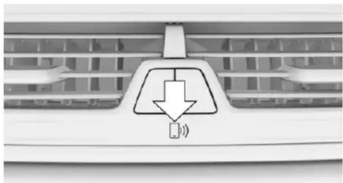
Close-up of a car air conditioner front panel with a downward arrow and sound icon (no text or symbols)The NFC antenna is in the instrument panel below the hazard warning flashers.
The device must be unlocked while pairing. compatible devices, refer to page 42.
Pairing is also possible while driving.
-
Activate the NFC function on the device, see the owner's manual of the device
-
Hold the device close to the NFC antenna.
-
Compare the control number on the Control Display with the control number on the display of the device. Confirm the control number on the device and on the Control Display.
or
Confirm the connection on the device.
- The device is connected and displayed in the device list.
There is a display of which features the mobile phone supports, refer to page 42.
Depending on which functions are already occupied, the device is connected with the phone, additional phone, or music function.
If pairing was unsuccessful: What to do if..., refer to page 47.
Pairing the snap-in adapter in the rear with the vehicle
The Bluetooth passkey on the back of the snap-in adapter is known.
The snap-in adapter is installed in the center armrest.
▶ Operating readiness is switched on.
The SIM card is inserted in the snap-in adapter or the SIM Access Profile is active.
About iDrive:
- "My Vehicle"
- "System settings"
- "Mobile devices"
-
"Connect new device"
-
Press the button on the snap-in adapter for approx. 3 seconds, until the signal tone sounds once.
The LED above the button flashes green.
- Enter the Bluetooth passkey for the snap-in adapter at the Control Display.
- "Telephone"
- The device is connected and displayed in the device list.
WLAN connection
Functional requirements
▶ ConnectedDrive contract.
Data contract with a service provider.
▶ WLAN-capable device.
▶ WLAN activated on the device.
▶ WLAN hotspot activated in the vehicle.
▶ Vehicle is stationary.
▶ Operating readiness switched on.
Activating WLAN hotspot
About iDrive:
- "My Vehicle"
- "System settings"
- "Mobile devices"
- "Settings"
- "Internet hotspot"
Connecting device with WLAN hotspot
About iDrive:
- "My Vehicle"
- "System settings"
- "Mobile devices"
- "Connect new device"
- "Internet hotspot"
Hotspot name and hotspot code are displayed on the Control Display.
- Search for WLAN networks on the device. Select network name on the device.
- Enter hotspot code on the device and connect.
The device connects to the hotspot via WLAN.
With the first Internet usage via the WLAN hotspot, data volume must be purchased from a service provider.
All devices connected via the WLAN hotspot use this data volume.
If necessary, data volume can be purchased from the ConnectedDrive Store.
WiFi connection
Pair the vehicle entirely on the front or rear Control Display.
About iDrive:
- "My Vehicle"
- "System settings"
- "Mobile devices"
- "Connect new device"
- "Miracast"
The WiFi name of the vehicle is displayed on the Control Display.
- Search for WiFi devices in the surroundings of the device.
The WiFi name of the vehicle appears on the device display. Select the WiFi name of the vehicle. - Compare the control number on the Control Display with the control number on the display of the device. Confirm the control number on the device and on the Control Display.
- The device is connected and displayed in the device list.
If pairing was unsuccessful: What to do if..., refer to page 47.
Additional functions
After initial pairing
The device is connected with the vehicle within a short period of time if the engine is
running or the operating readiness is switched on.
The data stored on the SIM card or in the mobile phone are transferred to the vehicle after recognition.
For some devices, certain settings may be necessary, e.g. authorization, see owner's manual of the device.
▶ After one-time pairing, the devices are automatically recognized and reconnected when operating readiness is switched on.
Configuring the device
Functions can be activated or deactivated for paired and connected devices.
About iDrive:
- "My Vehicle"
- "System settings"
- "Mobile devices"
- Select the desired device.
- Select desired setting.
If a function is assigned to a device, the function will be deactivated where appropriate for a device that is already connected and the device will be disconnected.
Connecting a specific device
About iDrive:
- "My Vehicle"
- "System settings"
- "Mobile devices"
- Select device.
- "Connect device"
The functions that were assigned to the device before unpairing are assigned to the device when it is reconnected. If the device is already connected, these functions are deactivated.
Disconnecting the device
The connection of the device to the vehicle is disconnected.
The device remains pairs and can be connected again, refer to page 45.
About iDrive:
- "My Vehicle"
- "System settings"
- "Mobile devices"
- Select device.
- "Disconnect device"
Deleting the device
The device is disconnected and removed from the device list.
About iDrive:
- "My Vehicle"
- "System settings"
- "Mobile devices"
- Select device.
- "Delete device"
Swapping the telephone and additional telephone
If two mobile phones are connected to the vehicle, the functions of phone and additional phone can be switched.
About iDrive:
- "My Vehicle"
- "System settings"
- "Mobile devices"
- "Settings"
- "Swap telephone 1 and 2"
Software Update
General information
The vehicle supports various external devices depending on the current software version. With a software update, compatibility with the vehicle can be improved, so that the vehicle can support new mobile phones or new external devices, e.g.
Updates and related current information are available at www.bmw.com/update.
Displaying the current version
The currently installed software is displayed.
About iDrive:
- "My Vehicle"
- "System settings"
- "Software update"
- "Show current version"
If an update has been carried out before, select the desired version to display additional information.
Updating software via USB
The software may only be updated when the vehicle is stationary.
About iDrive:
- Store the file for the software update in the main directory of a USB flash drive.
- Connect the USB data storage to an USB interface, refer to page 221.
- "My Vehicle"
- "System settings"
- "Software update"
- "Update software"
- "USB"
- "Install software"
- "OK"
- Await the updating.
- Confirm system restart.
Updating software via BMW Teleservices
Software update via BMW Teleservices is country-specific and may not be available.
The software is first transferred into the vehicle and can then be installed. The software can be installed at a time different from the time of transfer.
The software can be transferred while driving, and if the journey is interrupted it will resume automatically the next time the vehicle is driven. All other functions remain available during the transfer. Wireless reception must be available for the transfer to take place.
Installation of the software must only be carried out while the vehicle is stationary.
About iDrive:
- Turn on operations.
- "My Vehicle"
- "System settings"
- "Software update"
- "Update software"
- "TeleService"
- "Load update"
The update is loaded, however not installed.
- ▷ "Install software"
The loaded update is installed.
This step can be carried out at a later point in time.
▶ If the update should not be installed, it can be removed again.
"Remove update"
The following steps are omitted.
- "OK"
- Await the updating.
- Confirm system restart.
Restoring the software version
The software version before the last software update or the version before the first software update can be restored.
The software may only be restored when the vehicle is stationary.
About iDrive:
- "My Vehicle"
-
"System settings"
-
"Software update"
- "Restore software"
- ▷ "Previous version"
The previous software version is re-stored.
▶ "Default software settings"
The first software version is restored.
- "Remove software"
or
"Remove software"
- "OK"
- Wait for restore.
- Confirm system restart.
What to do if...
Information on compatible mobile phones, refer to page 42.
The mobile phone could not be paired or connected.
Is Bluetooth activated in the vehicle and on the mobile phone? Activate Bluetooth in the vehicle and on the mobile phone.
Do the Bluetooth passkeys on the mobile phone and the vehicle match? Enter the same passkey on the mobile phone and via iDrive.
▶ Did it take longer than 30 seconds to enter the passkey? Repeat pairing.
▷ Is NFC activated on the mobile phone? Activate NFC on the mobile phone.
Is distance from mobile phone to near-field communication antenna too far? Hold mobile phone directly to the antenna in the instrument cluster.
Do the control numbers on the mobile phone and vehicle match? Repeat the pairing procedure.
Are too many Bluetooth devices connected to the mobile phone or vehicle? Delete connections with other devices if needed.
Is Bluetooth audio activated? Deactivate Bluetooth audio.
▶ Delete all known Bluetooth connections from the device list on the mobile phone prior to pairing. Start new device search.
Is the mobile phone in power-save mode or does it have only a limited remaining battery life? Charge the mobile phone in the snap-in adapter, wireless charging storage or via the charging cable.
▶ Depending on the mobile phone, it is possible that only one mobile phone can be connected to the vehicle. Unpair the connected mobile phone from the vehicle and pair and connect only one mobile phone.
The mobile phone no longer reacts.
▶ Switch the mobile phone off and on again.
▶ Ambient temperatures too high or too low? Do not subject the mobile phone to extreme ambient temperatures.
The telephone functions are not available.
▶ Configure the mobile phone and connect it with the telephone or auxiliary phone function.
No or not all phone book entries are displayed, or they are incomplete.
▶ Transmission of the phone book entries is not yet complete.
It is possible that only the phone book entries of the mobile phone or the SIM card are transmitted.
It may not be possible to display phone book entries with special characters.
The number of phone book entries to be stored is too high.
▶ Is the data volume of the contact too large, e.g., due to stored information such as notes? Reduce the data volume of the contact.
Is the mobile phone connected as an audio source? Configure the mobile phone and
connect it with the telephone or auxiliary phone function.
The phone connection quality is poor.
The strength of the Bluetooth signal on the mobile phone can be adjusted, depending on the mobile phone.
▶ Insert the mobile phone into the snap-in adapter or place it in the area of the center console.
▶ Insert mobile phone into the wireless charging tray.
Adjust the volume of the microphone and loudspeakers separately.
If all points in this list have been checked and the required function is still not available, contact the hotline, a dealer's service center or another qualified service center or repair shop.
Integrated Owner's Manual in the vehicle
Vehicle features and options
This chapter describes all standard, country-specific and optional features offered with the series. It also describes features that are not necessarily available in your car, e.g., due to the selected options or country versions. This also applies to safety-related functions and systems. The respectively applicable country provisions must be observed when using the respective features and systems.
Integrated Owner's Manual in the vehicle
The concept
The Integrated Owner's Manual can be displayed on the Control Display. It specifically describes features and functions found in the vehicle.
Components of the Integrated Owner's Manual
The Integrated owner's manual consists of four parts, which offer various levels of information or possible access.
Quick Reference Guide
The Quick Reference Guide provides information how to operate the car, how to use basic vehicle functions or what to do in case of a breakdown. This information can also be displayed while driving.
Search by images
Image search provides information and descriptions. This is helpful when the terminology for a feature is not at hand.
Keyword search
Search for information and descriptions by entering terms selected from the index.
Videos
The basic functions of selected systems are explained in the videos.
Select components
Press button.
2. "My Vehicle"
3. "Owner's Manual"
4. Select desired setting.
Scrolling through the owner's manual
Turn controller, until the next or previous contents are displayed.
Context help - Owner's Manual to the temporarily selected function
You may open the relevant information directly.
Opening via the iDrive
To move directly from the application on the Control Display to the Options menu:
- "Owner's Manual"
Opening when a Check Control message is displayed
Directly from the Check Control message on the Control Display:
"Owner's Manual"
Changing between a function and the Owner's Manual
To switch from a function, e. g., radio, to the Owner's Manual on the Control Display and to alternate between the two displays:

-
OPTION Press button.
-
"Owner's Manual"
- Select the desired page in the Owner's Manual.

- ☐ Press button again to return to last displayed function.

- ☐ Press button to return to the page of the Owner's Manual displayed last.
To alternate permanently between the last displayed function and the Owner's Manual repeat steps 4 & 5. Opens a new display every time.
Programmable memory buttons
General information
The jumps into the Owner's Manual can be stored on the Programmable memory buttons, refer to page 28, and called up directly.
Storing
- Select the desired entry point via iDrive:
▶ "Quick reference"
▶ "Search by pictures"
▶ "Keyword search"
▶ "Animations"
- Press desired button and hold for more than 2 seconds.
Executing
Press the corresponding button.
The owner's manual is directly dis-
played via the selected entry point.
text_image
START STOP ENGINE Online Edition for Part no. 0140 2 964 330 - VI/15Controls
This chapter is intended to provide you with information that will give you complete control of your vehicle. All features and accessories that are useful for driving and your safety, comfort and convenience are described here.
Opening and closing
Vehicle features and options
This chapter describes all standard, country-specific and optional features offered with the series. It also describes features that are not necessarily available in your car, e. g., due to the selected options or country versions. This also applies to safety-related functions and systems. The respectively applicable country provisions must be observed when using the respective features and systems.
Remote control/key
General information
The vehicle is supplied with two remote controls with integrated key.
Every remote control holds a replaceable battery.
You may set the key functions depending on the optional features and country-specific version. For Settings, refer to page 67.
The vehicle stores personal settings for every remote control. Profile, refer to page 58.
The remote controls hold information on required maintenance. Service data in the remote control, refer to page 279.
Overview
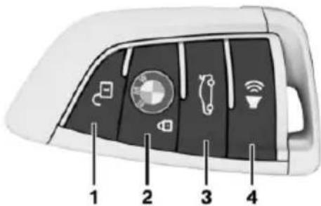
text_image
Diagram of a car dashboard with labeled buttons and icons, numbered 1 to 4 for identification.1 Unlocking
2 Locking
3 Opening the trunk lid
4 Panic mode
Integrated key
text_image
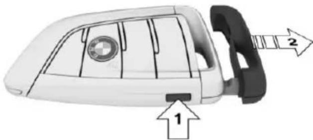
Diagram of a car rear bumper with labeled parts and directional arrows indicating movement or positioning.Press button, arrow 1, and remove the key, arrow 2.
The integrated key fits the following locks:
Driver's door.
▷ Glove compartment.
The glove compartment contains a switch for separately securing the trunk lid, refer to page 65.
Replacing the battery
natural_image
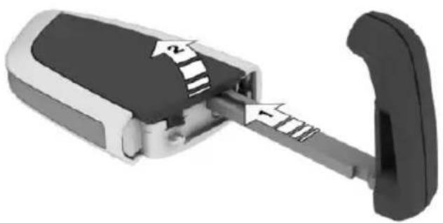
3D mechanical component diagram showing internal structure with numbered arrows (no text or symbols)- Remove integrated key from remote control.
- Raise the cover of the battery compartment, arrow 1.
- Remove the cover of the battery compartment, arrow 2.
- Insert a battery of the same type with the positive side facing up.
- Press the cover closed.

Take old battery to a collection point, a dealer's service center or another qualified service center or repair shop.
New remote controls
New remote controls are available from a dealer's service center or another qualified service center or repair shop.
Loss of the remote controls
The lost remote control can be blocked by a dealer's service center or another qualified service center or repair shop.
Emergency detection of remote control
Engine readiness can also be activated in the following situations:
▶ Interference of radio transmission to remote control by external sources e.g., by radio masts.
▶ Empty battery in remote control.
▶ Interference from radio transmissions through mobile devices in close proximity to remote control.
▶ Interference of radio transmission by charger while charging items such as mobile devices in the vehicle.
A Check Control message is displayed when an attempt is made to start the engine or activate engine readiness.
Activation of drive-ready state via emergency detection of the remote control
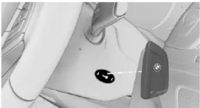
natural_image
Interior view of a car showing the seat, dashboard, and car seatbelt (no visible text or symbols)If a respective Check Control message appears, hold the remote control with its back against the marked area on the steering column. The tailgate button on the remote control should be at the same height as the marked area. Press the Start/Stop button within 10 seconds while pressing the brake pedal.
If the remote control is not recognized: slightly change the height position of the remote control and repeat the procedure.
BMW display key
General information
Instead of a standard remote control, the vehicle is equipped with the BMW display key with an additional mechanical key. If the BMW display key is used, the mechanical key should be carried along, e.g. in the wallet.
The BMW display key supports all functions of the standard remote control. Beyond that, the following functions are available.
▶ Display status of doors and windows.
▶ Display status of the alarm system.
▶ With parked-car heating: operate parked-car heating.
Without parked-car heating: operate parked-car ventilation.
▶ Call up range with available fuel.
▶ Display service information.
Emergency detection of the BMW display key
The description for the emergency detection of the remote control, refer to page 55, also applies for the BMW display key. However, the locking button should be at the height of the marking.
Overview
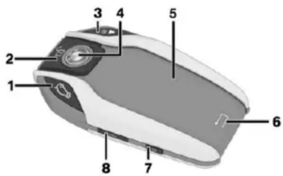
text_image
1 2 3 4 5 6 7 81 Opening the trunk lid
2 Unlocking
3 Panic mode
4 Locking
5 Display
6 Back
7 Switching the display on/off
8 Micro-USB charging port
Reception area
The number of available remote control functions depends on the distance from the vehicle.
▷ When you are in close proximity to the vehicle, all functions are available.
The status information can be called up in the extended reception area.
With parked-car heating: the parked-car heating can be operated.
Without parked-car heating: the parked-car ventilation can be operated.
Outside of the reception range of the vehicle, you can only display the last transmitted status information from the vehicle.
The symbol is shown on the display if one of the buttons is pressed outside of the reception range.
Display
Setup
The display is divided into the upper status line, the information area and the lower status line.
The upper status line displays the following information:
▶ Vehicle secured.
Vehicle not secured.
▷ Set time in the vehicle.
Charge state of the battery in the remote control.
The information area can be used to access information and perform additional functions.
The lower status line indicates whether or not the remote control is within reception range, refer to page 56.
▶ "Connected": Remote control is in the reception range.
▶ "Updated": Remote control is outside of the reception range. It indicates when the
last data transfer from the vehicle took place.
Controls
If the information area contains more than one page, then page indicators are shown beneath the information.
○●○ The indicator for the current page has been filled in.
Swipe to the right or left with a finger to change between the pages.
If additional information is available on a page, tap the appropriate symbol.
← Touch the arrow symbol beneath the display to return to the original page.
Switching the display on/off
The display will go out automatically after a brief period to conserve battery power.
To hide the display manually, press the button on the left side of the remote control. Overview, refer to page 56.
Show the display:
-
Press button on the left side of the remote control.
-
Then, swipe with your finger from bottom to top to unlock the screen lock.
Completely switch off the display to increase the usable battery life.
-
Press and hold the button on the left side of the remote control for longer than 4 seconds.
-
"OK" tap.
Press button on the left side of the remote control to switch on the switched-off display.
Operating concept
Depending on the equipment, there are up to five main menus that provide access to the sub-menus.
The following overview shows, using which main menus the information and functions can be accessed.
Menu Information/Function
| "Security information" | Door statusAlarm system statusAfter alarm triggering: date, time, and reason for triggering the alarm |
| Window statusGlass sunroof status | |
| "Vehicle information" | Maintenance indicators of Condition Based Service CBS, refer to page 279Status of the roadside parking lamp |
| "MOBILITY INFO" | Range with available fuel |
| "Climate control setting" | With parked-car heating: operate parked-car heating, refer to page 209.Without parked-car heating: operate parked-car ventilation, refer to page 209. |
Charging the remote control battery
If the charge state of the remote control battery declines, the display is switched off automatically. The battery must be recharged before the display can be switched back on. The operability of the standard buttons is retained until the battery is completely run down.
To charge the remote control battery:
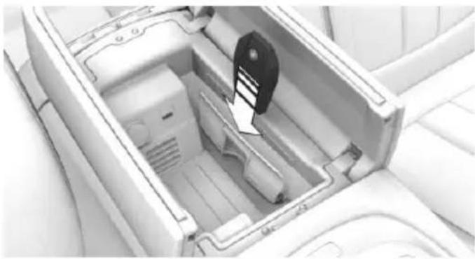
natural_image
Interior view of a car airfoil with visible internal components and no text or symbolsPlace remote control with the lock button upward in the bulge of the wireless charging station underneath the center armrest.
Connect the remote control via the micro USB socket on the left side to a USB port.
Software information
To display information stored in the BMW display key about the OpenSource software used, proceed as follows:
- Menu "Security information"
- Tap symbol.
- Tap the symbol three times.
To end the display:
Tap symbol.
Profile
The concept
In the profiles, individual settings for several drivers can be saved and called up again at a later time.
General information
There are three profiles with which personal vehicle settings can be stored. Every remote control has one of these profiles assigned.
If the vehicle is unlocked using a remote control, the assigned personal profile will be activated. All settings stored in the profile are automatically applied.
If several drivers use their own remote control, the vehicle will adjust the personal settings
during unlocking. These settings are also restored, if the vehicle has been used in the meantime by a person with a different remote control.
Changes to the settings are automatically saved in the profile currently activated.
If another profile is selected via iDrive, the settings saved in it will be applied automatically. The new profile is assigned to the remote control currently used.
There is an additional profile available that is not assigned to any remote control: "Just drive off (guest)". It can be used to apply settings in the vehicle without changing the personal profiles.
Active profile
After switching on the Control Display, the name of the active profile is displayed.
It is possible to jump directly to the Profile management, refer to page 59, in order to select your own profile, for example. This allows you to call up personal vehicle settings if you did not unlock the vehicle with your own key.
-
"Change driver profile"
-
Select profile, refer to page 59.
As soon as the engine is started or any key is pressed, the last selected key is displayed on the Control Display.
To exit the welcome screen via iDrive:
"Start system"
Adjusting
The settings for the following systems and functions are saved in the active profile. The scope of storable settings is country- and equipment-dependable.
▶ Unlocking and locking.
▶ Lights.
▶ Climate control.
▷ Radio.
▶ Instrument cluster.
▶ Programmable memory buttons.
▶ Volumes, tone.
▶ Control Display.
▶ Navigation.
▷ TV.
▶ Park Distance Control PDC.
▶ Rearview camera
▶ Side View.
▶ Head-up Display.
▶ Driving Dynamics Control.
▶ Seat position, exterior mirror position, steering wheel position.
▶ Cruise control.
▶ Intelligent Safety.
Night vision.
Profile management
Selecting a profile
Regardless of the remote control in use a different profile may be activated.
About iDrive:
- "My Vehicle"
- "Driver profiles"
- Select profile.
- "OK"
▶ All settings stored in the called-up profile are automatically applied.
The called-up profile is assigned to the remote control being used at the time.
If the profile is already assigned to a different remote control, this profile will apply to both remote controls. It cannot be differentiated anymore between the settings for the two remote controls.
Guest profile
The guest profile is for individual settings that are stored in none of the three personal profiles.
This can be useful for drivers who are using the vehicle temporarily and do not have their own profile.
About iDrive:
- "My Vehicle"
- "Driver profiles"
- "Just drive off (guest)"
- "OK"
The guest profile cannot be renamed. It is not assigned to the current remote control.
Rename profile
A personal name can be assigned to the active profile to avoid confusion between the profiles.
About iDrive:
- "My Vehicle"
- "Driver profiles"
The profile marked with this symbol can be renamed. - Select profile.
- "Change driver profile name"
- Enter profile name.
- Select the symbol.
Resetting the profile
The settings of the active profile are reset to their default values.
About iDrive:
- "My Vehicle"
- "Driver profiles"
The profile marked with this symbol can be reset. - Select profile.
- "Reset driver profile"
Exporting profiles
Most settings of the active profile can be exported.
This can be helpful for securing and retrieving personal settings, before delivering the vehicle to a workshop, e.g. The profiles backed up can be taken into another vehicle.
The following export options are available:
▶ Via ConnectedDrive.
▶ Via USB interface, refer to page 221, to a USB device.
About iDrive:
- "My Vehicle"
- "Driver profiles"
The profile marked with this symbol can be exported. - Select profile.
- "Export driver profile"
- ▷ USB device: "USB device"
Select USB device as needed.
▶ ConnectedDrive.
Importing profiles
The existing settings of the active profile are overwritten with the settings of the imported profile.
About iDrive:
- "My Vehicle"
- "Driver profiles"
The profile marked with this symbol can be overwritten.
- Select profile.
- "Import driver profile"
- Select the medium using which the profile was exported.
▶ USB device: "USB device"
Select USB device as needed.
▶ ConnectedDrive.
- Select profile.
Using the remote control
Information

WARNING
People or animals in the vehicle can lock the doors from the inside and lock themselves in. The vehicle can then not be opened from the outside. There is risk of injuries. Take the remote control along so that the vehicle can be opened from the outside.
Unlocking
Press button on the remote control.
Depending on the settings, refer to page 67, the following access points are unlocked:
▶ Driver's door and fuel filler flap.
▶ All doors, tailgate, and fuel filler flap.
In addition, the following functions are executed:
The settings saved in the profile, refer to page 58, are applied.
The interior lights are being switched on, unless they were manually switched off. Switching the interior lights on and off manually, refer to page 133.
The welcome lamps are switched on, if it is dark outside, door handle lighting and the Welcome Light Carpet are also switched on. These functions must be activated in the Settings, refer to page 130.
Press the remote control button again to switch on Welcome Light Carpet for the already unlocked vehicle.
The rear sliding visor is traveled into the position, where it was prior to locking.
Anti-theft protection is switched off.
The alarm system, refer to page 69, is disarmed.
After opening the driver's door, the vehicle is ready for operation, refer to page 20.
Convenient opening
Press and hold this button on the remote control after unlocking.
The windows and the glass sunroof are opened, as long as the button on the remote control is pressed.
Locking

WARNING
For some country-specific variants, un-locking from the inside is only possible with special knowledge.
If people must spend a longer time in the vehicle while it is very hot or cold outside, there is risk of injuries or danger to life. Do not lock the vehicle from the outside when there are people in it.
The driver's door must be closed.

Press button on the remote control.
▶ All doors, the tailgate, and the fuel filler flap are locked.
The rear sliding visor is being closed.
Anti-theft protection is switched on. It prevents the doors from being unlocked using the lock buttons or the door opener.
The alarm system, refer to page 69, is armed.
Switching on exterior lighting

Press button on the remote control with the vehicle locked.
The interior lights are being switched on, unless they were manually switched off. Switching the interior lights on and off manually, refer to page 133.
In the dark, door handle lighting and Welcome Light Carpet are switched on if these functions were activated. For Settings, refer to page 67.
If the button is pressed again within 10 seconds after vehicle was locked, the interior motion sensor and tilt alarm sensor of the anti-theft warning system, refer to page 70, are turned off. After locking, wait 10 seconds before pressing the button again.
Panic mode
You can trigger the alarm system if you find yourself in a dangerous situation.

Press button on the remote control and hold for at least 3 seconds.
To switch off the alarm: press any button.
Opening the tailgate

CAUTION
During opening, the trunk lid pivots back and up. There is risk of property damage. Make sure that the area of movement of the tailgate is clear during opening and closing.
Press and hold button on the remote control for approx. one second.
The trunk lid opens, regardless of whether the vehicle was previously locked or unlocked.
To avoid locking it into the vehicle, do not place the remote control in the cargo area.
Depending on the features and the country version, it is also possible to have door unlocked. Create the settings, refer to page 67.
If the doors were not unlocked, the trunk lid is locked again as soon as it closes.
Switching on the headlight courtesy delay feature

Press button on the remote control.
The duration can be set in the Control Display.
Malfunction
Remote control detection by the vehicle can among others be malfunctioning under the following circumstances:
The battery of the remote control is discharged. Replace the battery, refer to page 55.
▶ Interference of the radio connection from transmission towers or other equipment with high transmit power.
▶ Shielding of the remote control due to metal objects.
▶ Interference of the radio connection from mobile phones or other electronic devices in direct proximity.
Do not transport the remote control together with metal objects or electronic devices.
In the case of interference, the vehicle can also be unlocked and locked from the outside without remote control, refer to page 62.
For US owners only
The transmitter and receiver units comply with part 15 of the FCC/Federal Communication Commission regulations. Operation is governed by the following:
FCC ID:
▷ LX8766S.
▷ LX8766E.
▷ LX8CAS.
▷ LX8CAS2.
MYTCAS4.
Compliance statement:
This device complies with part 15 of the FCC Rules. Operation is subject to the following two conditions:
This device may not cause harmful interference, and
- this device must accept any interference received, including interference that may cause undesired operation.
Any unauthorized modifications or changes to these devices could void the user's authority to operate this equipment.
Without remote control
From the outside

WARNING
For some country-specific variants, un-locking from the inside is only possible with special knowledge.
If people must spend a longer time in the vehicle while it is very hot or cold outside, there is risk of injuries or danger to life. Do not lock the vehicle from the outside when there are people in it.

CAUTION
The door lock is permanently joined with the door. The door handle can be moved. When pulling the door handle with the integrated key inserted, paint or key can be damaged. There is risk of property damage. Remove the integrated key before pulling the outside door handle.
- Pull and hold the door handle outward with one hand.

natural_image
Close-up of a mechanical component with a curved wire and an arrow pointing to it (no text or symbols visible)- Guide one finger of the other hand from the back under the lid, push the palpable release outward and remove the lid.
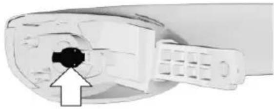
natural_image
Close-up of a white electronic device with a black connector and a white arrow pointing to it (no visible text or symbols)- Unlock or lock the door lock using the integrated key, refer to page 54.
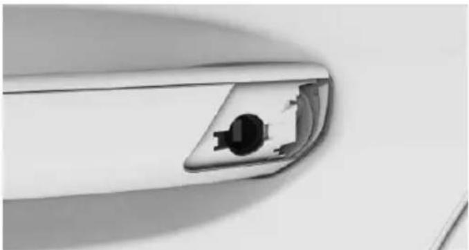
natural_image
Close-up of a car's side panel showing the engine compartment (no text or symbols visible)The other doors must be unlocked or locked from the inside.
Alarm system
The alarm system is not armed if the vehicle is locked with the integrated key.
The alarm system is triggered when the door is opened, when the vehicle is unlocked via the door lock.
In order to terminate this alarm, unlock vehicle with the remote control, if needed, through emergency detection of the remote control, refer to page 55.
From the inside
Unlocking and locking

natural_image
Interior view of a car showing the side panel and airflow direction (no text or symbols visible)Via the buttons for the central locking system.
Pressing the button unlocks the vehicle.
Pressing the button locks the vehicle if the front doors are closed.
The vehicle is not secured against theft when locking.
The fuel filler flap remains unlocked.
In the event of a severe accident, the vehicle is automatically unlocked. The hazard warning system and interior lights come on.
Unlocking and opening
Press the central locking system button to unlock the doors together, and then pull the door handle above the armrest.
Doors
Automatic Soft Closing
To close the doors, push lightly.
It is closed automatically.

WARNING
Body parts can be jammed on operating the doors. There is risk of injuries. Make sure that the area of movement of the doors is clear during opening and closing.
Trunk lid
Information
To avoid locking it into the vehicle, do not place the remote control in the cargo area.
Opening
During opening, the trunk lid pivots back and up. Ensure that adequate clearance is available before opening.
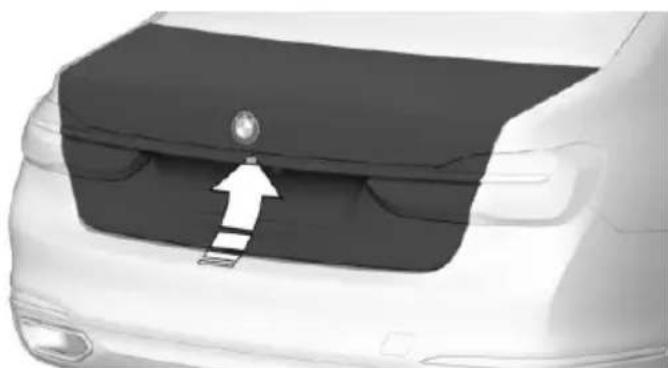
natural_image
Side view of a car's rear bumper with a white arrow pointing to the grille (no text or symbols visible)▶ Press button on the exterior of the trunk lid.
▶ Press and hold button on the remote control for approx. one second.
As the case may be, the doors are also unlocked. Opening with the remote control, refer to page 61.
▶ Press button in the storage compartment of the driver's door.
The opening procedure is interrupted:
▷ By pressing the button again.
When starting the engine.
▷ When the vehicle starts moving.
▷ By pressing the button on the inside of the tailgate.
Closing
Without Comfort Access:
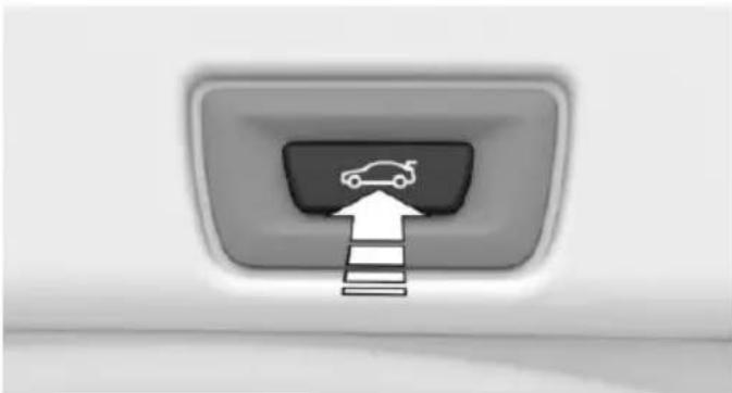
natural_image
Interior view of a vehicle rearview with a car icon and an upward arrow pointing to the front panel (no text or symbols)▶ Press button on the inside of the trunk lid. The trunk lid closes automatically.
With Comfort Access:
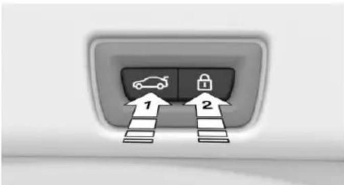
text_image
Diagram showing car and lock icons pointing to a vehicle inside a vehicle seat, with arrows labeled 1 and 2 indicating directions.▶ Press button, arrow 1, on the inside of the trunk lid.
▷ Press button, arrow 2.
The vehicle will be locked after closing the tailgate. The driver's door must be closed for this purpose and the remote control must be outside of the vehicle in the area of the trunk lid.
An acoustic signal sounds and the tailgate closes.
The closing operation is interrupted:
▷ By pressing the button again.
When starting the engine.
The vehicle starts off with jerks.

WARNING
Body parts can be jammed when operating the tailgate. There is risk of injuries. Make sure that the area of movement of the tailgate is clear during opening and closing.
Manual operation
In the event of an electrical malfunction, manually operate the unlocked trunk lid slowly and smoothly.

WARNING
Body parts can be jammed when operating the tailgate. There is risk of injuries. Make sure that the area of movement of the tailgate is clear during opening and closing.
Locking separately
The trunk lid can be locked separately with the switch in the glove compartment. If the glove compartment is locked, the trunk lid cannot be opened.
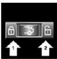
▶ Trunk lid secured, arrow 1.
▶ Trunk lid not secured, arrow 2.
Slide the switch into the arrow 1 position. This secures the trunk lid and disconnects it from the central locking system.
This is beneficial when the vehicle is parked using valet service. The remote control can be handed out without the integrated key.
Emergency unlocking
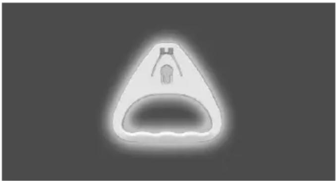
natural_image
Simple 3D-rendered object resembling a funnel or trough with a small protrusion, no text or symbols present.Pull the handle inside the trunk.
The trunk lid unlocks.
Comfort Access
Information
To avoid locking it into the vehicle, do not place the remote control in the cargo area.
The concept
The vehicle can be accessed without activating the remote control.
All you need to do is to have the remote control with you, such as in your pants pocket.
The vehicle automatically detects the remote control when it is in close proximity or in the car's interior.
Comfort Access supports the following functions:
▶ Unlocking/locking of the vehicle.
▶ Convenient closing.
▶ Opening/closing the tailgate individually.
▶ Open/close trunk lid with no-touch activation.
▶ Start the engine.
Functional requirements
There are no external sources of interference nearby.
To lock the vehicle, the remote control must be located outside of the vehicle near the doors.
The next unlocking and locking cycle is not possible until after approx. 2 seconds.
The engine can only be started if the remote control is in the vehicle.
Unlocking
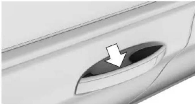
natural_image
Close-up of a car interior with a circular vent and a white arrow pointing to the hole (no text or symbols)Grasp the handle of a vehicle door completely, arrow.
This corresponds to pressing the remote control button.
Locking
The driver's door must be closed.
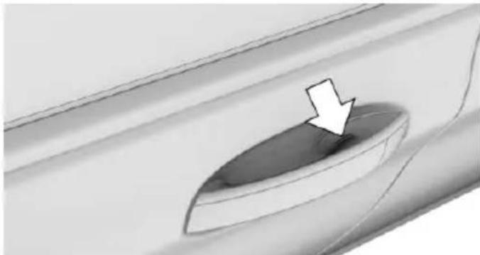
natural_image
Close-up of a car door handle with a white arrow pointing to the interior (no text or symbols)Touch the grooved surface on the handle of a closed vehicle door, arrow, with your finger for approx. one second without grasping the door handle.
This corresponds to pressing 🔗 the remote control button.
Convenient closing

WARNING
With convenient closing, body parts can be jammed. There is risk of injuries. Make sure that the area of movement of the doors is clear during convenient closing.
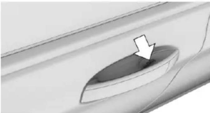
natural_image
Close-up of a car interior with a white arrow pointing to a circular opening, no text or symbols visibleTouch the grooved surface on the handle of a closed vehicle door, arrow, with your finger and hold it there without grasping the door handle.
This corresponds to pressing and holding the remote control button.
In addition to locking, the windows and the glass sunroof close and the exterior mirrors fold in.
Opening the tailgate individually
Press button on the exterior of the trunk lid.
This corresponds to pressing the remote control button.
The situation of the doors does not change.
Opening and closing the trunk lid with no-touch activation
The concept
The trunk lid can be opened and closed with no-touch activation using the remote control you are carrying. Two sensors detect a forward-directed foot motion in the center of the area at the rear of the car and the tailgate opens and closes.
Information

WARNING
During no-contact activation, vehicle parts may be touched, e.g. hot exhaust system. There is risk of injuries. With the foot motion, make sure there is steady stance and do not touch the vehicle.
If the remote control is in the sensor area, the tailgate can be closed or opened inadvertently by an unconscious or alleged recognized foot movement.
The sensor range reaches approx. 5 ft/1.50 m behind the area at the rear of the car.

WARNING
Body parts can be jammed when operating the tailgate. There is risk of injuries. Make sure that the area of movement of the tailgate is clear during opening and closing.

CAUTION
During opening, the trunk lid pivots back and up. There is risk of property damage. Make sure that the area of movement of the tailgate is clear during opening and closing.
Foot movement to be carried out
- Place in the center behind the vehicle, about an arm's length from the vehicle rear.
- Move a foot in the direction of travel as far under the vehicle as possible and immediately pull it back. With this movement, the leg must pass through the ranges of both sensors.
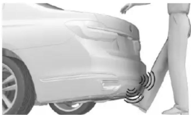
natural_image
Side view of a car with sensor waves on the side and a person standing nearby (no text or symbols visible)The trunk lid opens, regardless of whether it was previously locked or unlocked.
Before the opening, the hazard warning system flashes.
To close the tailgate, repeat the foot movement.
Before closing, the hazard warning system flashes and an acoustic signal sounds.
The closing of the trunk lid has no effect on the locking of the vehicle. To avoid locking it into the vehicle, do not place the remote control in the cargo area.
Another foot movement can interrupt the closing operation.
Malfunction
Remote control detection by the vehicle can among others be malfunctioning under the following circumstances:
The battery of the remote control is discharged. Replace the battery, refer to page 55.
▶ Interference of the radio connection from transmission towers or other equipment with high transmit power.
▶ Shielding of the remote control due to metal objects.
▶ Interference of the radio connection from mobile phones or other electronic devices in direct proximity.
Do not transport the remote control together with metal objects or electronic devices.
In the case of a malfunction, unlock and lock the vehicle using the buttons of the remote control or using the integrated key, refer to page 62.
Adjusting
General information
Settings are stored for the profile currently used.
Unlocking
Doors
About iDrive:
- "My Vehicle"
-
"Vehicle settings"
-
"Doors/Key"
-
"Driver's door"
or

"All doors"
- Select desired setting:
▶ "Driver's door"
Only the driver's door and the fuel filler flap are unlocked. Pressing again un-locks the entire vehicle.
▶ "All doors"
The entire vehicle is unlocked.
Trunk lid
Depending on optional features and country version, this setting is not offered in some cases.
About iDrive:
-
"My Vehicle"
-
"Vehicle settings"
-
"Doors/Key"
-
"Tailgate"
or

"Tailgate and door(s)"
- Select desired setting:
▶ "Tailgate"
The trunk lid is opened.
▷ "Tailgate and door(s)"
The trunk lid is opened and the doors are unlocked.
Confirmation signals from the vehicle
About iDrive:
-
"My Vehicle"
-
"Vehicle settings"
-
"Doors/Key"
-
Deactivate or activate the desired confirmation signals.
▶ "Flash for lock/unlock"
▶ "Acoustic signal for lock/unlock"
Automatic locking
About iDrive:
-
"My Vehicle"
-
"Vehicle settings"
-
"Doors/Key"
-
Select desired setting:
"Lock automatically"
The vehicle locks automatically after a short period of time if no door is opened.
▷ "Lock after starting to drive"
The vehicle locks automatically after you drive off.
Automatic unlocking
About iDrive:
-
"My Vehicle"
-
"Vehicle settings"
-
"Doors/Key"
-
"Unlock at end of trip"
After drive readiness is ended by pressing the Start/Stop button, the locked vehicle is automatically unlocked.
Retrieving the seat, mirror, and steering wheel settings
On unlocking of the vehicle, the positions for the driver's seat, exterior mirror, and steering wheel stored in the profile are automatically retrieved.
WARNING There is risk
There is risk of jamming when moving the seats. There is risk of injuries or risk of property damage. Make sure that the area of movement of the seat is clear prior to any adjustment.
About iDrive:
- "My Vehicle"
- "Driver profiles"
- Select profile.
- "Last seat position automatic"
The adjustment procedure is interrupted:
▶ When a seat position switch is pressed.
▷ When a button of the seat, mirror, and steering wheel memory is pressed briefly.
Alarm system
The concept
When the vehicle is locked, the vehicle alarm system responds to:
▶ Opening a door, the hood or the trunk lid.
▶ Movements in the interior.
Changes in the vehicle tilt, e. g., during attempts at stealing a wheel or when towing the car.
▶ Disconnected battery voltage.
The alarm system briefly signals tampering:
▶ By sounding an acoustic alarm.
▶ By switching on the hazard warning system.
By flashing the high beams.
Arming and disarming the alarm system
When you unlock or lock the vehicle, either with the remote control or via the Comfort Access, the alarm system is disarmed or armed at the same time.
Door lock and armed alarm system
The alarm system is triggered when the door is opened, when the vehicle is unlocked via the door lock.
Trunk lid and armed alarm system
The trunk lid can be opened even when the alarm system is armed.
After the trunk lid is closed, it is locked and monitored again when the doors are locked. The hazard warning system flashes once.
Panic mode
You can trigger the alarm system if you find yourself in a dangerous situation.

Press button on the remote control and hold for at least 3 seconds.
To switch off the alarm: press any button.
Indicator lamp on the interior rearview mirror
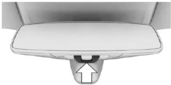
natural_image
Close-up of a white mechanical component with a U-shaped groove and an arrow pointing upward (no text or symbols)The indicator lamp flashes briefly every 2 seconds:
The alarm system is armed.
The indicator lamp flashes after locking:
Doors, hood or tailgate are not correctly closed. Correctly closed access points are secured.
After 10 seconds, the indicator lamp flashes continuously. Interior motion sensor and tilt alarm sensor are not active.
When the still open access is closed, interior motion sensor and tilt alarm sensor will be switched on.
The indicator lamp goes out after unlocking:
The vehicle has not been tampered with.
The indicator lamp flashes after unlocking until drive readiness is switched on, but no longer than approx. 5 minutes:
An alarm has been triggered.
Tilt alarm sensor
The tilt of the vehicle is monitored.
The alarm system responds in situations such as attempts to steal a wheel or when the car is towed.
Interior motion sensor
The windows and glass sunroof must be closed for the system to function properly.
Avoiding unintentional alarms
The tilt alarm sensor and interior motion sensor can be switched off together, such as in the following situations:
▶ In automatic car washes.
In duplex garages.
During transport on trains carrying vehicles, at sea or on a trailer.
▶ With animals in the vehicle.
Switching off the tilt alarm sensor and interior motion sensor

Press the remote control button again within 10 seconds as soon as the vehicle is locked.
The indicator lamp lights up for approx. 2 seconds and then continues to flash.
The tilt alarm sensor and interior motion sensor are turned off until the vehicle is locked again.
Switching off the alarm
▶ Unlock the vehicle using the remote control, if needed, through emergency detection of the remote control, refer to page 55.
With Comfort Access: if you are carrying the remote control on your person, grasp the driver side or front passenger side door handle completely.
Power windows
Information

WARNING
Unattended children or animals can move the vehicle and endanger themselves and traffic, e.g. with the following actions:
▶ Pressing the Start/Stop button.
▶ Releasing the parking brake.
▶ Opening and closing of doors or windows.
▶ Shifting the selector lever into neutral.
▶ Using vehicle equipment.
There is risk of accidents or injuries. Do not leave children or animals unattended in the vehicle. Carry remote control along when exiting and lock the vehicle.
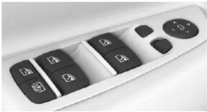
natural_image
Close-up of a black remote control panel with icons for navigation, function, and function buttons (no text or symbols visible)Opening
▶ Press the button to the resistance point.
The window opens while the switch is held.
▶ Press the switch beyond the resistance point.
The window opens automatically. Pressing the switch again stops the motion.
See also: Convenient opening, refer to page 61, via remote control.
Closing

WARNING
When operating the windows, body parts and objects can be jammed. There is risk of injuries or risk of property damage. Make sure that the area of movement of the windows is clear during opening and closing.
▶ Pull the switch to the resistance point.
The window closes while the switch is held.
▶ Pull the switch beyond the resistance point.
The window closes automatically. Pulling again stops the motion.
See also: closing by means of Comfort Access, refer to page 65.
Pinch protection system

WARNING
When operating the windows, body parts and objects can be jammed. There is risk of injuries or risk of property damage. Make sure that the area of movement of the windows is clear during opening and closing.

WARNING
Accessories on the windows such as antennas can impact jam protection. There is risk of injuries. Do not install accessories in the area of movement of the windows.
If closing force exceeds a specific margin as a window closes, closing is interrupted.
The window reopens slightly.
Closing without the pinch protection system

WARNING
When operating the windows, body parts and objects can be jammed. There is risk of injuries or risk of property damage. Make sure
that the area of movement of the windows is clear during opening and closing.
In case of danger from the outside or if ice might prevent normal closing, proceed as follows:
- Pull the switch past the resistance point and hold it there.
The pinch protection is limited and the window reopens slightly if the closing force exceeds a certain margin. - Pull the switch past the resistance point again within approx. 4 seconds and hold it there.
The window closes without jam protection.
Safety switch
The concept
With the safety switch for the rear, it is possible to block particular functions. This makes sense, for example, if children or animals are carried in the rear.
General information
The following functions can be locked using the switch:
▶ Opening and closing of the rear windows using the switches in the rear.
▶ Operation of the roller sunblind in the rear window using the switches in the rear.
▶ Operation of the roller sunblinds in the side windows using the switches in the rear.
▶ Adjustment of the power rear seats.
▶ Operation of the rear sliding visor using the switches in the rear.
Information

WARNING
When operating the windows, body parts and objects can be jammed. There is risk of injuries or risk of property damage. Make sure
that the area of movement of the windows is clear during opening and closing.
In order to prevent uncontrolled closing of the windows, press the safety switch, e.g. if children or animals are carried in the rear.
Switching on and off
Press button.
The LED lights up if the safety func-
tion is switched on.
Roller sunblinds
General information
The safety switch, refer to page 71, in the driver's door can be used to prevent children, e.g., from operating the roller sunblinds using the switches in the rear.
BMW Touch Command
The roller sunblinds can also be operated using BMW Touch Command.
Information
If you are no longer able to move the roller sun-blinds after having activated them consecutively a number of times, the system is blocked for a limited time to prevent overheating. Let the system cool.
The roller sunblinds cannot be moved at low interior temperatures.
Roller sunblind in the rear window
Overview
Driver's door
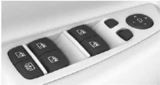
natural_image
Close-up of a white remote control with black buttons and icons (no readable text or symbols)
Button for the roller sunblind in the rear window.
Rear doors
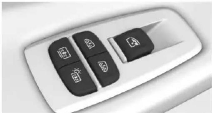
natural_image
Close-up of a car air conditioner control panel with four function buttons (no text or symbols visible)
Button for the roller sunblind in the rear window.
Controls
Press the button to open the closed roller sunblind or to close the open
roller sunblind.
If the button is pressed again during the movement, the roller sunblind is moved in the opposite direction.
Hold the button down to operate the roller sun-blinds on the rear window and on the side windows at the same time.
Roller sunblinds in the side windows
Overview
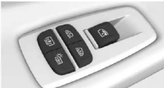
natural_image
Close-up of a car air conditioner control panel with four function buttons (no text or symbols visible)
Buttons for the roller sunblinds in the side windows.
Controls
Press the button to open the closed roller sunblind or to close the open
roller sunblind.
If the button is pressed again during the movement, the roller sunblind is moved in the opposite direction.
Glass sunroof
General information
The glass sunroof and the front sliding visor can be operated together or separately using the same switch. The rear sliding visor is operated using separate buttons.
The glass sunroof is operational when the standby state is switched on.
Information

WARNING
Body parts can be jammed on operating the glass sunroof. There is risk of injuries. Make sure that the area of movement of the glass sunroof is clear during opening and closing.

WARNING
Unattended children or animals can move the vehicle and endanger themselves and traffic, e.g. with the following actions:
▶ Pressing the Start/Stop button.
▶ Releasing the parking brake.
▶ Opening and closing of doors or windows.
▶ Shifting the selector lever into neutral.
▶ Using vehicle equipment.
There is risk of accidents or injuries. Do not leave children or animals unattended in the vehicle. Carry remote control along when exiting and lock the vehicle.
Overview
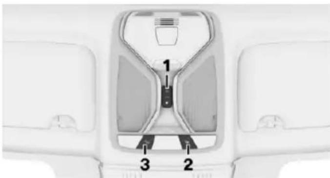
text_image
1 2 31 Open/close the glass sunroof/sliding visor. With panoramic glass sunroof: open/close glass sunroof/front sliding visor.
2 With panoramic glass sunroof: close rear sliding visor.
3 With panoramic glass sunroof: open rear sliding visor.
Lifting/closing glass sunroof
Push switch briefly upward.
The closed glass sunroof is tilted and the sliding visor opens slightly.
The opened glass sunroof closes until it is in its tilted position. The sliding visor does not move.
The tilted glass sunroof is being closed.
Opening/closing the glass sunroof and front sliding visor separately
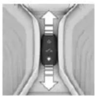
▶ Press the switch in the desired direction to the resistance point and hold it there.
The sliding visor opens, as long as the switch is held down. If the sliding visor is already fully open, the glass sunroof opens.
The glass sunroof closes as long as the switch is held down. If the glass sunroof is already closed or in the tilted position, the sliding visor closes.
▶ Press the switch in the desired direction past the resistance point.
The sliding visor opens automatically. If the sliding visor is already fully open, the glass sunroof opens automatically.
The glass sunroof closes automatically. If the glass sunroof is already closed or in the tilted position, the sliding visor closes automatically.
Pressing the switch upward stops the motion.
Opening/closing the glass sunroof and front sliding visor together
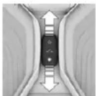
Briefly press the switch twice in succession in the desired direction past the resistance point.
The glass sunroof and sliding vis- sor move together. Pressing the
switch upward stops the motion.
▶ See also: Convenient opening, refer to page 61, via remote control.
▶ See also: closing by means of Comfort Access, refer to page 65.
Comfort position
If the glass sunroof is not automatically completely opened, the comfort position has been attained. In this position the wind noises in the interior are the least.
If desired, continue the movement by Pressing the switch.
Opening/closing the rear sliding visor
On the roofliner control panel
Press button to open the rear sliding visor.
Press button again to stop the movement.
Press button to close the sliding visor. Press button again to stop the move-
ment.
On the control panel in the rear doors
The rear sliding visor cannot be used via the buttons in the rear if the safety function, refer to page 71, is switched on.
Press the button to open the closed sliding visor or to close the open slid-
ing visor.
Press button again to stop the movement.
When the button is pressed again, the sliding visor will move in the opposite direction.
BMW Touch Command
The rear sliding visor can also be operated using BMW Touch Command.
Actions during unlocking/locking
If the vehicle is locked from the outside, the rear sliding visor is automatically closed.
During unlocking, the sliding visor is automatically traveled into the position, where it was prior to locking.
Pinch protection system
If the closing force when closing the glass sun-roof exceeds a certain value, the closing movement is stopped, beginning at approximately the middle of the opening in the roof, or from the tilted position during closing.
The glass sunroof reopens slightly.

WARNING
Body parts can be jammed on operating the glass sunroof. There is risk of injuries. Make sure that the area of movement of the glass sunroof is clear during opening and closing.
Closing from the open position without pinch protection
If there is an external danger, proceed as follows:
- Press the switch forward beyond the resistance point and hold.
The pinch protection is limited and the glass sunroof reopens slightly if the closing force exceeds a certain margin. - Press the switch forward again beyond the resistance point and hold until the glass sunroof closes without jam protection. Make sure that the closing area is clear.
Closing from the raised position without pinch protection
If there is an external danger, push the switch forward past the resistance point and hold it.
The glass sunroof closes without jam protection.
Initializing after a power failure
After a power failure during the opening or closing process, the glass sunroof can only be operated to a limited extent.
Initializing the system
The system can be initialized when the vehicle is stationary and the engine is running.
During the initialization, the glass sunroof closes without jam protection.

WARNING
Body parts can be jammed on operating the glass sunroof. There is risk of injuries. Make sure that the area of movement of the glass sunroof is clear during opening and closing.
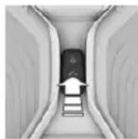
Press the switch up and hold it until the initialization is complete:
▶ Initialization begins within 15 seconds and is completed when the glass sun-roof and sliding visor are completely closed.
The glass sunroof closes without jam protection.
Adjusting
Vehicle features and options
This chapter describes all standard, country-specific and optional features offered with the series. It also describes features that are not necessarily available in your car, e.g., due to the selected options or country versions. This also applies to safety-related functions and systems. The respectively applicable country provisions must be observed when using the respective features and systems.
Sitting safely
The ideal seating position can make a vital contribution to relaxed, fatigue-free driving.
The seating position plays an important role in an accident in combination with:
▶ Safety belts, refer to page 80.
▶ Head restraints, refer to page 82.
Airbags, refer to page 136.
Front seats
Information

WARNING
Seat adjustments while driving can lead to unexpected movements of the seat. Vehicle control could be lost. There is risk of an accident. Only adjust the side on the driver's side when the vehicle is stationary.

WARNING
With a backrest inclined too far to the rear, the protective effect of the safety belt cannot be ensured anymore. There is a danger of sliding under the safety belt in an accident. There is risk of injuries or danger to life. Adjust the seat prior to starting the trip. Adjust the
backrest in an as upright position as possible and do not adjust again while driving.

WARNING
There is risk of jamming when moving the seats. There is risk of injuries or risk of property damage. Make sure that the area of movement of the seat is clear prior to any adjustment.
Electrically adjustable seats
Overview
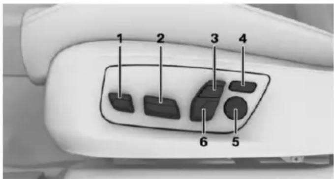
text_image
1 2 3 4 6 51 Thigh support
2 Forward/back, height, tilt
3 Shoulder support
4 Backrest width
5 Lumbar support
6 Backrest, head restraint
General information
The seat adjustment for the driver's seat is stored for the profile currently used. When the vehicle is unlocked via the remote control, the position is automatically retrieved if the Function, refer to page 68, is activated for this purpose.
Adjustments in detail
▶ Forward/back.
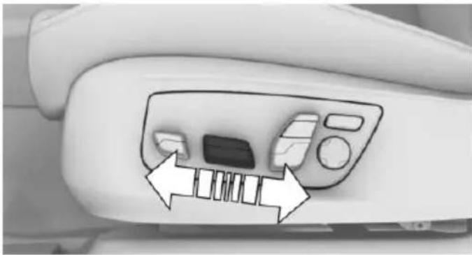
natural_image
Close-up of a car air conditioner panel with directional arrows indicating airflow or movement (no text or symbols)▷ Height.
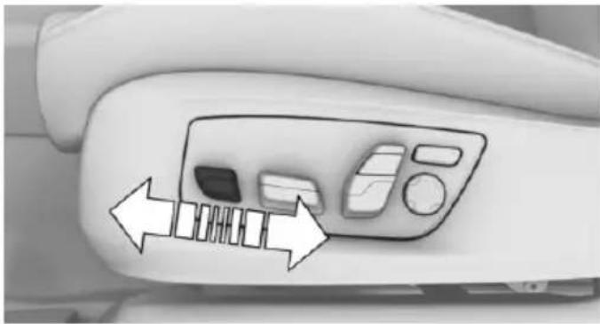
natural_image
Close-up of a car air conditioner panel with directional arrows indicating airflow or movement (no text or symbols)Lumbar support
The curvature of the seat backrest can be adjusted in a way that it supports the lumbar region of the spine. The lower back and the spine are supported for upright posture.
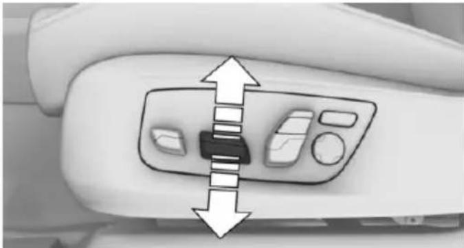
natural_image
Close-up of a car's front panel with directional arrows indicating left and right movement (no text or symbols)▶ Seat tilt.
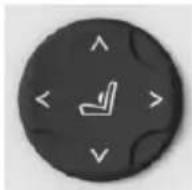
▶ Press the front/rear section of the switch: The curvature is increased/decreased.
▶ Press the upper/lower section of the switch: The curvature is shifted up/down.
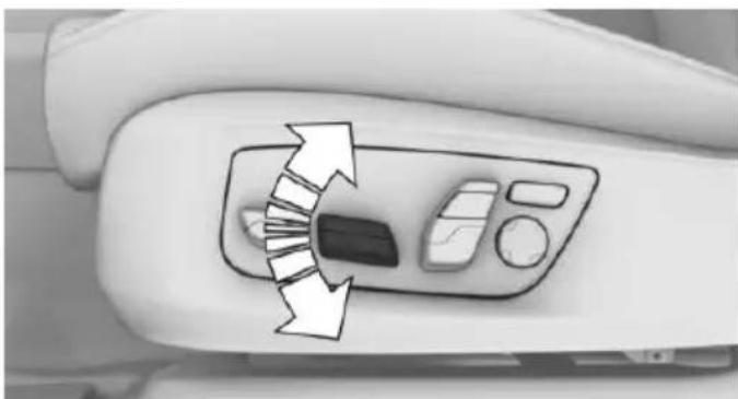
natural_image
Close-up of a car's front panel with directional arrows indicating clockwise motion (no text or symbols)▶ Backrest tilt.
Backrest width
Change the width of the back-rest using the side wings to adjust the lateral support.
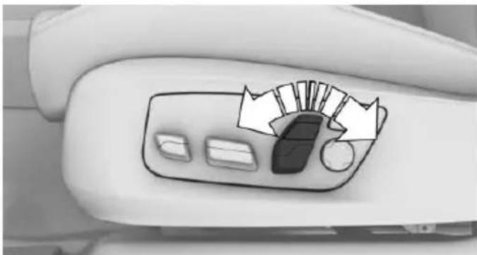
natural_image
Close-up of a car's side panel with a hand cursor pointing to the dashboard (no text or symbols visible)Thigh support.
Shoulder support
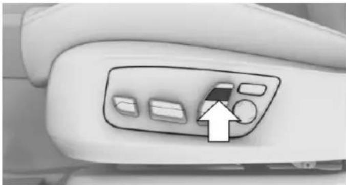
natural_image
Close-up of a car air conditioner control panel with an arrow pointing to the button (no text or symbols visible)Also supports the back in the shoulder area:
▶ Results in a relaxed seating position.
▶ Reduces strain on the shoulder muscles.
Gentleman function
The concept
The front passenger seat can be adjusted with the switches of the driver's seat, e.g. to increase the legroom in the rear.
Overview
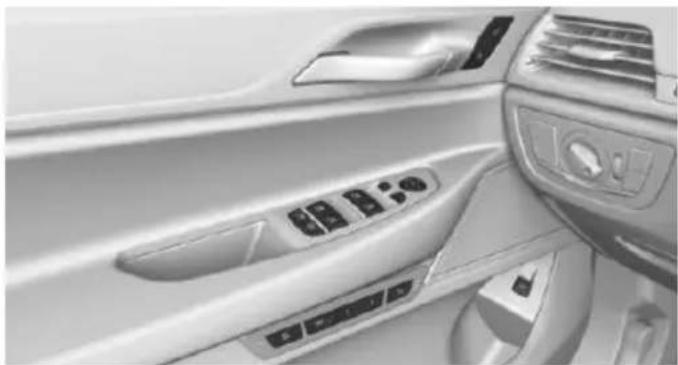
natural_image
Interior view of a car dashboard with control panel and air vent (no visible text or symbols)
Gentleman function
Switching on
- Press button. The LED lights up.
- Adjust the front passenger seat on your own seat.
If needed, store the memory position, refer to page 87, for the front passenger seat.
Switch off
Press button and hold until LED goes out.
The function deactivates itself automatically after some time.
BMW Touch Command
The front passenger seat can also be operated using BMW Touch Command.
Rear seats
General information
The seats in the rear can be used using the seat adjustment switch in the center armrest or via BMW Touch Command.
Information

WARNING
There is a risk of jamming when folding down the center armrest in the rear. There is risk of injuries. Make sure that the area of movement of the center armrest is clear during folding down.
Electrically adjustable seats
Overview
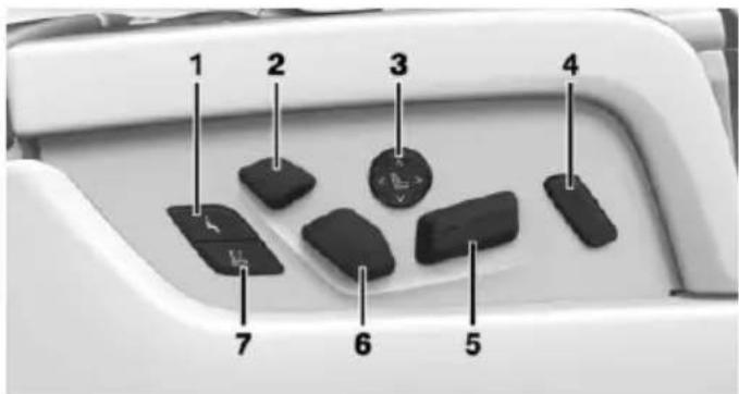
text_image
1 2 3 4 7 6 51 Resetting to standard position
2 Head restraint, shoulder support
3 Lumbar support
4 Folding the footrest out/in
5 Forward/backward, tilt
6 Backrest
7 Adjust front passenger seat
If the safety switch, refer to page 71, is pressed, the seats cannot be adjusted.
Adjustments in detail
Forward/back.
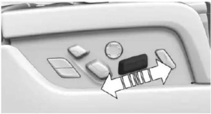
natural_image
Close-up of a car's front panel with buttons and a battery icon, no visible text or symbolsSeat tilt.
Shoulder support
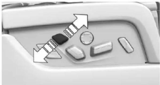
natural_image
Close-up of a car interior panel with directional arrows and component icons (no readable text or symbols)Also supports the back in the shoulder area:
▶ Results in a relaxed seating position.
▶ Reduces strain on the shoulder muscles.
Folding the footrest out/in
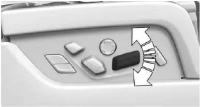
natural_image
Top-down view of a car's side panel with buttons and directional arrows indicating flow or movement (no text or symbols)▶ Backrest tilt.
Press the upper/lower section of the switch:
The footrest on the backrest of the front passenger seat is folded out/in.
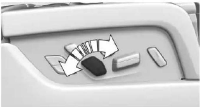
natural_image
Close-up of a car's side panel with directional arrows and buttons, no visible text or symbolsLumbar support
The curvature of the seat backrest can be adjusted in a way that it supports the lumbar region of the spine. The lower back and the spine are supported for upright posture.
▶ Press the front/rear section of the switch:
The curvature is increased/decreased.
▶ Press the upper/lower section of the switch:
The curvature is shifted up/ down.
The distance between the front passenger seat and the rear seat must be sufficiently large to unfold the footrest.
Adjusting the front passenger seat from the rear
The concept
The front passenger seat can be operated from the rear, e.g. to increase the legroom in the rear.
General information
With the button for adjusting the Shoulder support, refer to page 79, it is possible to set the angle of the screen in the rear on the passenger side.
Adjusting
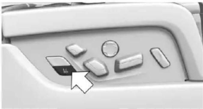
natural_image
Close-up of a car's front panel with buttons and a cursor pointing to the left side (no text or symbols visible)-
L2 Press button.
-
Adjust the passenger seat, e.g., forward/back.
-
Press the button to deactivate the function.
The function deactivates itself automatically after some time.
Resetting to standard position
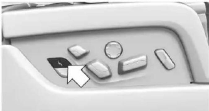
natural_image
Close-up of a computer keyboard mode dial with control buttons and an arrow pointing to the left (no text or symbols visible)Press button to reset to standard position.
The process is canceled if the button is pressed again.
Safety belts
Seats with safety belt
The vehicle has four or five seating positions, each of which is equipped with a safety belt.
General information
Always make sure that safety belts are being worn by all occupants before driving off.
For the occupants' safety the belt locking mechanism triggers early. Slowly guide the belt out of the holder when applying it.
Although airbags enhance safety by providing added protection, they are not a substitute for safety belts.
The upper shoulder strap's anchorage point will be correct for adult seat occupants of every build if the seat is correctly adjusted.
The two outer safety belt buckles, integrated into the rear seat, are for passengers sitting on the left and right.
The center rear safety belt buckle is solely intended for the center passenger.
Information
WARNING If the safety
If the safety belt is used by more than one person, the protective effect of the safety belt cannot be ensured anymore. There is risk of injuries or danger to life. Do not allow more than one person to wear a single safety belt. Infants and children are not allowed in an occupant's lap, but must be transported and respectively secured in designated child restraint systems.
WARNING The protect
The protective effect of the safety belts can be limited or lost when safety belts are fastened incorrectly. An incorrectly fastened safety belt can cause additional injuries, e.g. in the event of an accident or during braking and evasive maneuvers. There is risk of injuries or danger to life. Make sure that all occupants are wearing safety belts correctly.
Correct use of safety belts
▶ Wear the belt twist-free and as tight to your body as possible over your lap and shoulders.
▶ Wear the belt deep on your hips over your lap. The belt may not press on your stomach.
Do not wear the belt on your throat, rub it on sharp edges, guide it or jam it in across hard or fragile objects.
▶ Avoid thick clothing.
▶ Re-tighten the belt frequently upward around your upper body.
Buckling the belt
General information
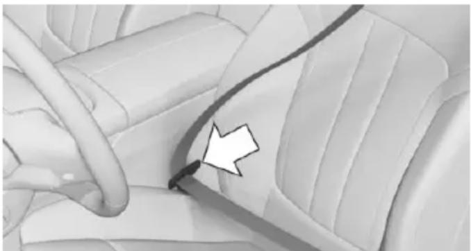
natural_image
Close-up of a car seatbelt with a white arrow pointing to the side panel (no text or symbols visible)Make sure you hear the latch plate engage in the belt buckle.
Tensioning the safety belt automatically
When the belt is closed, the driver's and passenger's belt straps are automatically tightened once after driving away.
Unbuckling the belt
- Hold the belt firmly.
- Press the red button in the belt buckle.
- Guide the belt back into its roll-up mechanism.
Safety belt reminder for driver's seat and front passenger seat

The indicator lamp lights up and a signal sounds. Make sure that the safety belts are positioned correctly. The safety belt reminder is active at speeds above approx. 6 mph/10 km/h. It can also be activated if objects are placed on the front passenger seat.
Safety mode
In critical situations, e.g., during full brake application, the front safety belts tighten automatically.
If the situation passes without an accident occurring, the belt tension relaxes.
If the belt tension does not loosen automatically, stop the vehicle and unbuckle the belt using the red button in the buckle. Fasten the belt before continuing on your trip.
Damage to safety belts

WARNING
The protective effect of the safety belts may not be fully functional or fail in the following situations:
▶ Safety belts are damaged, soiled or changed in any other way.
▶ Safety belt buckle is damaged or heavily soiled.
▶ Belt tensioners or belt retractors were modified.
Safety belts can be imperceptibly damaged in the event of an accident. There is risk of injuries or danger to life. Do not modify safety belts, safety belt buckles, belt tensioners, belt retractors or belt anchors and keep them clean. Have the safety belts checked after an accident at the dealer's service center or another qualified service center or repair shop.
Front head restraints
Information

WARNING
A missing protective effect due to removed or not correctly adjusted head restraints can cause injuries in the head and neck area. There is risk of injuries. Install head restraints on occupied seats prior to driving and make sure that the center of the head restraint supports the back of the head at eye level.

WARNING
Objects on the head restraint reduce the protective effect in the head and neck area. There is risk of injuries.
Do not use seat or head restraint covers.
Do not hang objects, e.g., clothes hangers, directly on the head restraint.
▶ Only use accessories that have been determined to be safe for attachment to a head restraint.
Do not use any accessories, e.g. pillows, while driving.
Correctly adjusted head restraint
General information
A correctly adjusted head restraint reduces the risk of injury to cervical vertebrae in the event of an accident.
Height
Adjust the head restraint so that its center is approximately at ear level.
Distance
Adjust the distance so that the head restraint is as close as possible to the back of the head.
Active head restraint
In the event of a rear-end collision with a certain severity, the active head restraint automatically reduces the distance from the head.
Wear and tear after accidents or when damaged otherwise:
Have the active head restraint checked and if needed replaced.
Adjusting the height
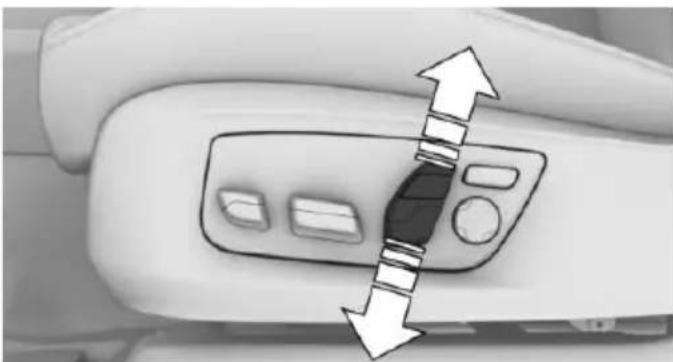
natural_image
Close-up of a car's side panel with directional arrows indicating movement or force (no text or symbols)Adjusting electrically.
Distance to back of head: manual head restraints
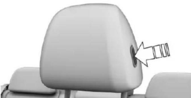
natural_image
Close-up of a car seat corner with a circular button and an arrow pointing to the side (no text or symbols)Forward: by pulling.
▶ Back: press the button and push the head restraint toward the rear.
Distance to back of head: electrical head restraints
The head restraint is automatically repositioned when the shoulder support is adjusted.
Adjusting the side extensions
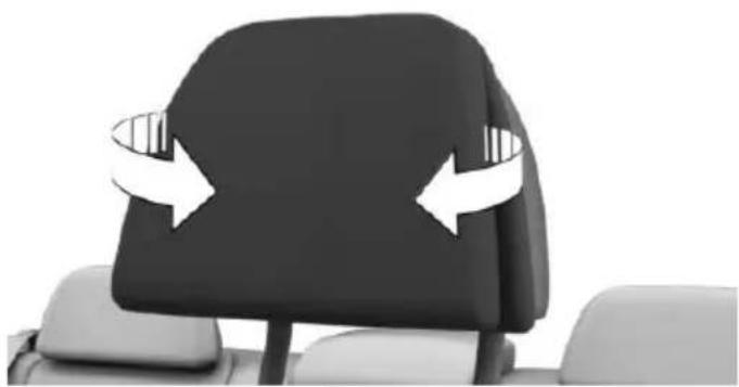
natural_image
Side view of a black and white car seat with two white directional arrows indicating rotational motion (no text or symbols)Fold forward for increased lateral support in the resting position.
Removing
The head restraints cannot be removed.
Rear head restraints
Information

WARNING
A missing protective effect due to removed or not correctly adjusted head restraints can cause injuries in the head and neck area. There is risk of injuries. Install head restraints on occupied seats prior to driving and make sure that the center of the head restraint supports the back of the head at eye level.

WARNING
Objects on the head restraint reduce the protective effect in the head and neck area. There is risk of injuries.
Do not use seat or head restraint covers.
Do not hang objects, e.g., clothes hangers, directly on the head restraint.
▶ Only use accessories that have been determined to be safe for attachment to a head restraint.
Do not use any accessories, e.g. pillows, while driving.
Correctly adjusted head restraint
General information
A correctly adjusted head restraint reduces the risk of injury to cervical vertebrae in the event of an accident.
Height
Adjust the head restraint so that its center is approximately at ear level.
Distance
Adjust the distance so that the head restraint is as close as possible to the back of the head.
Adjusting the center head restraint
To improve the view to the rear, the center head restraint can be folded to the rear. Only push the head restraint down if no one will be sitting in the center seat.
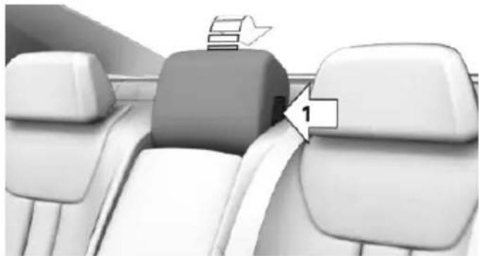
natural_image
Interior view of a car showing seat compartments and a highlighted section with number 1 (no text or symbols present)To the rear: press button, arrow 1, and fold the head restraint backward.
To the front: fold head restraint forward until the head restraint engages.
Adjusting the height
Manual head restraints
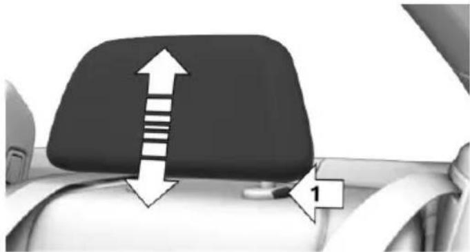
natural_image
Top-down view of a car seatbelt with directional arrows and label '1' (no text or symbols on the diagram itself)The height of the outer head restraints can be adjusted.
To raise: push.
To lower: press button, arrow 1, and push headrest down.
Power head restraints
Information

WARNING
Body parts can be jammed when moving the head restraint. There is risk of injuries.
Make sure that the area of movement is clear when moving the head restraint.
Button in the vehicle
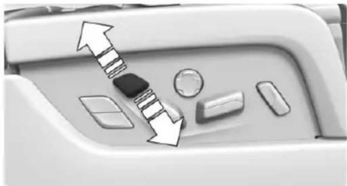
natural_image
Close-up of a car dashboard with directional arrows and control buttons (no text or symbols)The height of the head restraint can be adjusted electrically.
The height adjustment of the head restraint is deactivated when the safety switch for the rear windows, refer to page 71, has been pressed.
Adjusting the side extensions
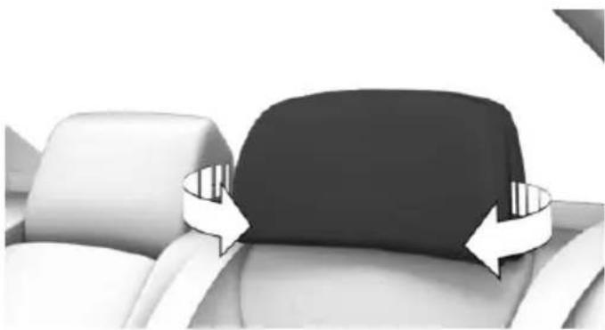
natural_image
Interior view of a car dashboard seat with white and black panels, showing side panel rotation (no text or symbols)Fold the side extensions on the head restraint forward for increased lateral support in the resting position.
Pillows for head restraints in the rear
Only use the pillow when the vehicle is switched off.
- There are two pushbuttons on the upper tab of the pillow. Pull the upper tab through the loop on the top of the head restraint.
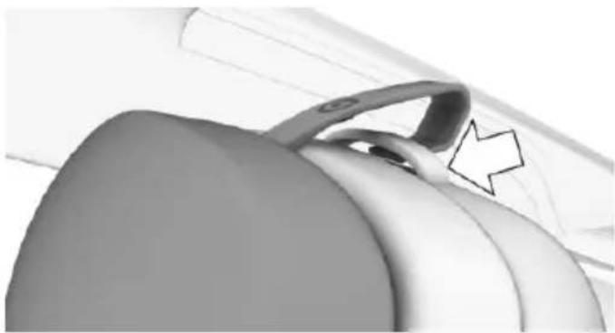
natural_image
Close-up of a car interior showing a handle and seat area, with a white arrow pointing to the handle (no text or symbols visible)- Close both pushbuttons.
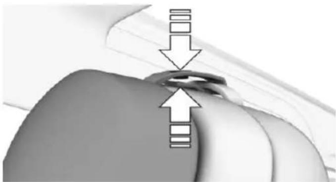
natural_image
Close-up of a mechanical component with directional arrows indicating movement or force (no text or symbols)- The head restraint folds into the topmost position. Close the pushbutton on the
lower tab and the pushbutton on the bottom of the head restraint.

natural_image
Close-up of a hand holding a small object with an arrow pointing upward, no visible text or symbolsRemoving
The head restraints cannot be removed.
Mirrors
Exterior mirrors
General information
The mirror on the passenger side is more curved than the driver's side mirror.
Depending on the vehicle equipment, the mirror setting is stored for the profile currently used. When the vehicle is unlocked via the remote control, the position is automatically retrieved if this function is active.
Information

WARNING
Objects reflected in the mirror are closer than they appear. The distance to the traffic behind could be incorrectly estimated, e.g. while changing lanes. There is risk of an accident. Estimate the distance to the traffic behind by looking over your shoulder.
Overview
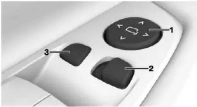
text_image
Diagram of a remote control interface with labeled buttons and directional arrows indicating navigation or movement.1 Adjusting 85
2 Left/right, Automatic Curb Monitor
3 Fold in and out 86
Selecting a mirror
To change over to the other mirror: Slide the switch.
Adjusting electrically

The setting corresponds to the direction in which the button is pressed.
Saving positions
Seat, mirror, and steering wheel memory, refer to page 87.
Adjusting manually
In case of electrical malfunction press edges of mirror.
Automatic Curb Monitor
The concept
If reverse gear is engaged, the mirror glass on the front passenger side is tilted downward. This improves your view of the curb and other low-lying obstacles when parking, e.g.
Activating
Slide the switch to the driver's side position.
- Engage selector lever position R.
Deactivating
Slide the switch to the passenger side mirror position.
Fold in and out

CAUTION
Depending on the vehicle width, the vehicle can be damaged in car washes. There is risk of property damage. Before washing, fold in the mirrors by hand or with the button.

Press button.
Possible at speeds up to approx. 15 mph/20 km/h.
Beneficial in the following situations:
In car washes.
On narrow roads.
For folding mirrors back out that were folded away manually.
Mirrors that were folded in are folded out automatically at a speed of approx. 25 mph/40 km/h.
Automatic heating
Both exterior mirrors are automatically heated whenever the engine is running.
Automatic dimming feature
Both exterior mirrors are automatically dimmed. Photocells are used to control the Interior rearview mirror, refer to page 86.
Interior rearview mirror, automatic dimming feature
Overview
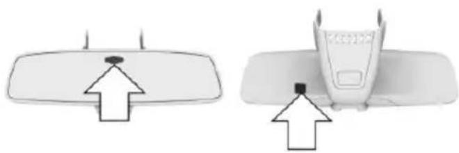
natural_image
Two technical diagrams showing a device with a sensor and an antenna, both pointing to a black dot (no text or symbols present)Photocells are used for control:
In the mirror glass.
On the back of the mirror.
Functional requirement
For proper operation:
▷ Keep the photocells clean.
Do not cover the area between the inside rearview mirror and the windshield.
Rear vanity mirror
Folding down
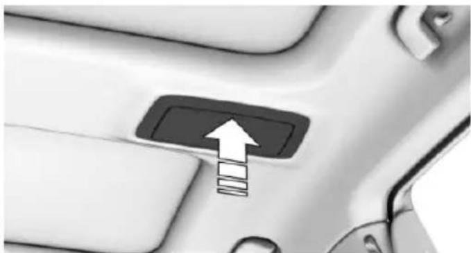
natural_image
Close-up of a car's door panel with an upward arrow and stacked boxes (no text or symbols visible)Press vanity mirror.
The vanity mirror folds down.
The angle can be adjusted by hand.
Folding up
Press the mirror up.
Steering wheel
Information

WARNING
Steering wheel adjustments while driving can lead to unexpected steering wheel movements. Vehicle control could be lost. There is risk of an accident. Adjust the steering wheel while the vehicle is stationary only.
Power steering wheel adjustment
Adjusting
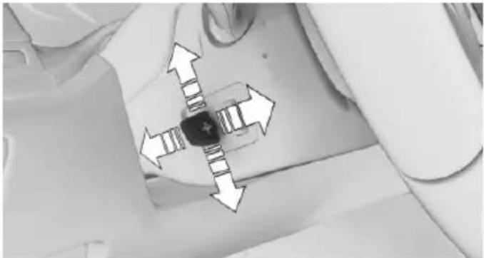
natural_image
Top-down view of a mechanical component with four directional arrows indicating movement or force (no text or symbols)Move the steering wheel to the preferred height and angle to suit your seating position.
Storing the position
Seat, mirror, and steering wheel memory, refer to page 87.
Heated steering wheel
Overview
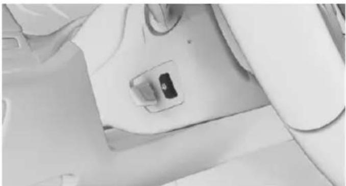
natural_image
Close-up of a white medical or surgical device with a small inset component (no visible text or symbols)
Heated steering wheel
Switching on/off
Press button.
On: the LED lights up.
▶ Off: the LED goes out.
If the trip is resumed within approx. 15 min, steering wheel heating is automatically activated again.
Seat, mirror, and steering wheel memory
The concept
Two different driver's seat, exterior mirror and steering wheel positions can be stored per profile, refer to page 58, and called up.
Information

WARNING
Using the memory function while driving can lead to unexpected seat or steering wheel movements. Vehicle control could be lost. There is risk of an accident. Only retrieve the memory function when the vehicle is stationary.

WARNING
There is risk of jamming when moving the seats. There is risk of injuries or risk of property damage. Make sure that the area of movement of the seat is clear prior to any adjustment.
Overview
Front
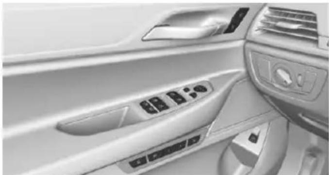
natural_image
Interior view of a car dashboard with control panels and air filters (no visible text or symbols)Rear
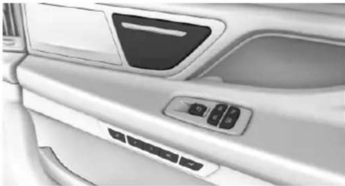
natural_image
Interior view of a car showing the dashboard, side panel, and control buttons (no text or symbols visible)Storing
- Set the desired position.
- SET Press button. The writing on the button lights up.
- Press desired button 1 or 2 while the LED is lit. Lighting of the writing goes out.
Button was pressed inadvertently: Press button again.
Lighting of the writing goes out.
Calling up settings
Comfort function
Press selected button 1 or 2.
The corresponding seat position is performed automatically.
The procedure stops when a switch for adjusting the seat or one of the buttons is pressed.
The comfort function is not available on the driver's seat while driving.
Safety mode
While driving, a profile can be called up on the driver's seat:
Press and hold the desired button 1 or 2 until the adjustment procedure is completed.
BMW Touch Command
The memory function can also be operated on the front passenger seat and in the rear via BMW Touch Command.
Massage function
The concept
Depending on the program, the massage function ensures relaxed muscles and better blood circulation and can avoid fatigue.
General information
Eight different massage programs can be selected:
▶ Pelvis activation.
▶ Upper body activation.
▶ Full body activation.
▶ Back massage.
▶ Shoulder massage.
▶ Lumbar massage.
▶ Upper body training.
▶ Full body training.
Overview
Front
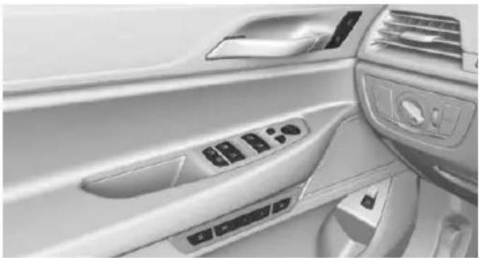
natural_image
Interior view of a car dashboard with control panel and air vent (no visible text or symbols)
Massage function
Rear

natural_image
Interior view of a car showing the dashboard and side panel with control buttons (no text or symbols visible)
Massage function
Switching on
Via the iDrive
- "My Vehicle"
- "Vehicle settings"
- "Seat comfort"
- Select desired seat.
- "Seat massage"
- "Level"
- Select intensity 1–3.
Using the button
Whole-body training is started.
Press button once for each massage level. The highest level is active when three LEDs are lit.
Switch off
Via the iDrive
- "My Vehicle"
- "Vehicle settings"
- "Seat comfort"
- Select desired seat.
- "Seat massage"
- "Level"
- "OFF"
Using the button
Press and hold the button, until the LEDs go out.
Adjusting the massage program
About iDrive:
- "My Vehicle"
- "Vehicle settings"
- "Seat comfort"
- Select desired seat.
- "Seat massage"
- Select desired setting.
BMW Touch Command
Operation of the massage function is also possible via BMW Touch Command.
Captain's chair
The concept
The Captain's chair offers maximum legroom and increased traveling comfort to the rear passenger on the front passenger's side.
General information
The following settings are applied to the seat automatically on system activation:
The front passenger's seat moves forward and adjusts the height if necessary.
▶ Backrest and head restraint of the front passenger seat are inclined forward.
The tilt of the screen in the rear is adjusted to the rest incline of the passenger's seat.
The head restraint on the backrest of the front passenger seat folds out.
The backrest of the rear seat inclines to the rear.
The adjusted end position can be manually adjusted, refer to page 78, and stored using the Memory function, refer to page 87, if needed.
Information

WARNING
If the Captain's chair is activated, the view on the right exterior mirror can be obstructed. There is risk of an accident. Adjust the front passenger seat such that the view on the exterior mirror is not obstructed.
Overview
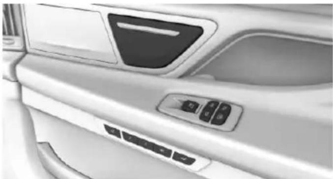
natural_image
Interior view of a car showing the dashboard and control panel (no text or symbols visible)
Captain's chair
Switching on

Press button.
Resetting to standard position
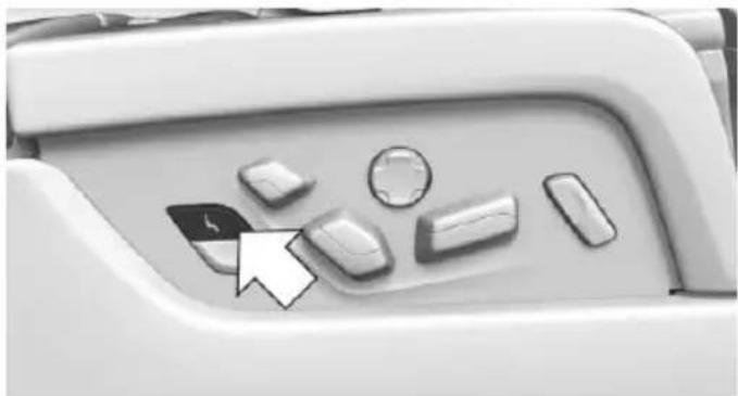
natural_image
Close-up of a computer keyboard mode dial with control buttons and an arrow pointing to the left (no text or symbols visible)
Press button to reset to standard position.
The process is canceled if the button is pressed again.
Vitality programs
The concept
Different muscles can be trained using the vitality program in the rear. Active movements help in preventing signs of fatigue.
General information
After each start of the vitalization program, there is a calibration run. Here the intensity of the exercises is set individually.
Videos on the respective screens in the rear show, which motions should be executed. A display informs about the still-remaining duration of each exercise. There is direct feedback to the exercise executed by a display of stars and a color bar display:
▷ Green: exercise was correctly executed.
Gray: the pressure was too weak.
▶ Red: the pressure was too weak.
The goal of the exercises is to keep the bar display in the green area as long as possible. Every exercise is evaluated by awarding stars.
Switching on
On the screens in the rear:
- "My Vehicle"
- "Seat comfort"
- "BMW Vitality Program"
Switch off
On the screens in the rear:
- Press left arrow button on the remote control in the rear.
- "Stop"
BMW Touch Command
The vitality program can also be operated using BMW Touch Command.
Seat and armrest heating
General information
The system heats seats and armrests as needed. Seat heating can also be used without armrest heating.
Overview
Front
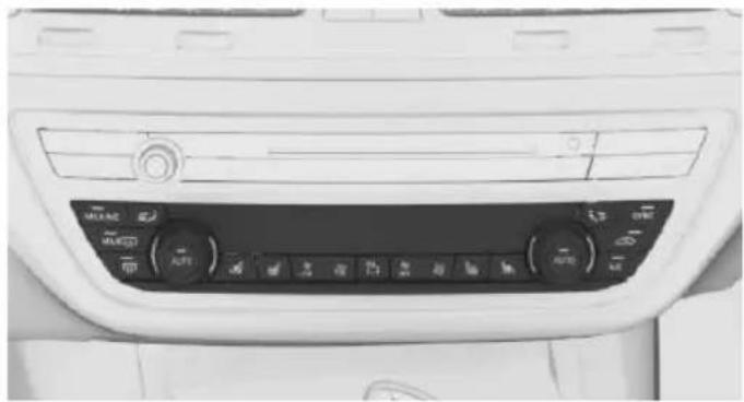
natural_image
Interior view of a car dashboard with control knobs and indicator lights (no visible text or symbols)
Seat and armrest heating
Rear
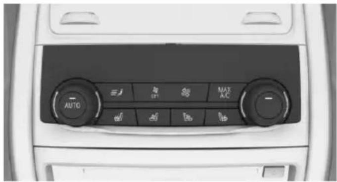
text_image
AUTO OPT MAX A.C
Seat and armrest heating
Switching on
Press button once for each temperature level.
Highest level if three bars are shown on the climate control display.
If the trip is continued within approx. 15 minutes, the seat and armrest heating is activated automatically with the temperature selected last.
When ECO PRO, refer to page 241, is activated, the heater output is reduced.
Switch off
Press button and hold until bar display on the climate control display goes
Temperature distribution
The heating action in the seat cushion and backrest can be distributed in different ways.
About iDrive:
- "My Vehicle"
- "Vehicle settings"
- "Climate functions"
-
"Seat and armrest heating"
-
Select desired seat.
- Pres the controller and turn to set the temperature distribution.
Switching armrest heating on/off
About iDrive:
- "My Vehicle"
- "Vehicle settings"
- "Climate functions"
- "Seat and armrest heating"
- Select desired seat.
- "Heat up armrest together with seat"
Active seat ventilation
The concept
The seat cushion and backrest surfaces are cooled by means of integrated fans.
The ventilation cools the seat, e. g., if the vehicle interior is overheated or for continuous cooling at high temperatures.
Overview
Front
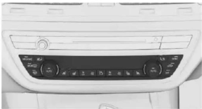
natural_image
Interior view of a car dashboard with air conditioners and control buttons (no visible text or symbols)
Active seat ventilation
Rear
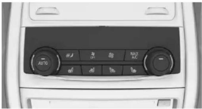
text_image
AUTO E CPT MAX A/C
Active seat ventilation
Switching on
Press button once for each ventilation level.
Highest level if three bars are shown on the climate control display.
After a short time, the system automatically moves down one level in order to prevent excessive cooling.
Switch off
Press button and hold until bar display on the climate control display goes
out.
Transporting children safely
Vehicle features and options
This chapter describes all standard, country-specific and optional features offered with the series. It also describes features that are not necessarily available in your car, e. g., due to
The right place for children
Information

WARNING
Unattended children or animals can move the vehicle and endanger themselves and traffic, e.g. with the following actions:
▶ Pressing the Start/Stop button.
▶ Releasing the parking brake.
▶ Opening and closing of doors or windows.
▶ Shifting the selector lever into neutral.
▶ Using vehicle equipment.
There is risk of accidents or injuries. Do not leave children or animals unattended in the vehicle. Carry remote control along when exiting and lock the vehicle.
Children should always be in the rear

WARNING
Persons shorter than 5 ft, 150 cm cannot correctly fasten the safety belt without suitable additional restraint systems. The protective effect of the safety belts can be limited or lost when safety belts are fastened incorrectly. An incorrectly fastened safety belt can cause additional injuries, e.g. in the event of an accident or during braking and evasive maneuvers. There is risk of injuries or danger to life. Secure persons shorter than 5 ft, 150 cm using suitable restraint systems.
Accident research shows that the safest place for children is in the back seat.
the selected options or country versions. This also applies to safety-related functions and systems. The respectively applicable country provisions must be observed when using the respective features and systems.
Only transport children younger than 13 years of age or shorter than 5 ft, 150 cm in the rear in child restraint systems provided in accordance with the age, weight and size of the child.
Children 13 years of age or older must wear a safety belt as soon as a suitable child restraint system can no longer be used due to their age, weight and size.
Children on the front passenger seat
Before using a child restraint system on the front passenger seat, ensure that the front, knee, and side airbags on the front passenger side are deactivated. Automatic deactivation of front-seat passenger airbags, refer to page 138.
Information

WARNING
Active front-seat passenger airbags can injure a child in a child restraint system when the airbags are activated. There is risk of injuries. Make sure that the front-seat passenger airbags are deactivated and that the PASSENGER AIRBAG OFF indicator lamp lights up.
Installing child restraint systems
Information
Pay attention to the specifications of the child restraint system manufacturer when selecting, installing, and using child restraint systems.

WARNING
The stability of the child restraint system is limited or compromised with incorrect seat adjustment or improper installation of the child seat. There is risk of injuries or danger to life. Make sure that the child restraint system fits securely against the backrest. If possible, adjust the backrest tilt for all affected backrests and correctly adjust the seats. Make sure that seats and backrests are securely engaged. If possible, adjust the height of the head restraints or remove them.
On the front passenger seat
Deactivating airbags

WARNING
Active front-seat passenger airbags can injure a child in a child restraint system when the airbags are activated. There is risk of injuries. Make sure that the front-seat passenger airbags are deactivated and that the PASSENGER AIRBAG OFF indicator lamp lights up.
After installing a child restraint system in the front passenger seat, make sure that the front, knee and side airbags on the front passenger side are deactivated.
Deactivate the front-seat passenger airbags automatically, refer to page 138.
Seat position and height
Before installing a child restraint system, move the front passenger seat as far back as possible and bring it up to medium height to obtain the best possible position for the belt and to
offer optimal protection in the event of an accident.
If the upper anchorage of the safety belt is located in front of the belt guide of the child seat, move the passenger seat carefully forward until the best possible belt guide position is reached.
Backrest width
Adjustable backrest width: before installing a child restraint system in the front passenger seat, open the backrest width completely. Do not change the backrest width again and do not call up a memory position.
Child seat security
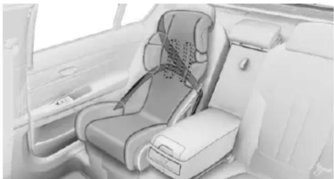
natural_image
Interior view of a car showing a car seat with passenger seat and driver seat (no text or symbols visible)The rear safety belts and the front passenger safety belt can be permanently locked to fasten child restraint systems.
The front passenger safety belt can be permanently locked to fasten child restraint systems.
Locking the safety belt
- Pull out the strap completely.
- Secure the child restraint system with the belt.
- Allow the strap to be pulled in and pull it tight against the child restraint system. The safety belt is locked.
Unlocking the safety belt
- Unbuckle the belt buckle.
- Remove the child restraint system.
- Allow the strap to be pulled in completely.
LATCH child restraint system
LATCH: Lower Anchors and Tether for Children.
Information
Pay attention to the operating and safety information of the child restraint system manufacturer when installing and using LATCH child restraint fixing system.
Mounts for the lower LATCH anchors
General information
The lower anchors may be used to attach the CRS to the vehicle seat up to a combined child and CRS weight of 65 lb/30 kg when the child is restrained by the internal harnesses.
Information

WARNING
If the LATCH child restraint fixing systems are not correctly engaged, the protective effect of the LATCH child restraint fixing system can be limited. There is risk of injuries or danger to life. Make sure that the lower anchors are securely engaged and that the LATCH child restraint fixing system fits securely against the backrest.
Position

The corresponding symbol shows the mounts for the lower LATCH anchors. Seats equipped with lower anchors are marked with a pair, 2, of LATCH symbols. It is not recommended to use the inner lower anchors of standard outer

LATCH positions to fasten a child restraint system on the middle seat. Use the vehicle seat belt instead for the middle seat.
Before installing LATCH child restraint systems
Pull the belt away from the area of the child restraint system.
Without comfort seats in the rear: Assembly of LATCH child restraint systems
- Install child restraint system, see manufacturer's information.
- Ensure that both LATCH anchors are properly connected.
With comfort rear seats: Assembly of LATCH child restraint fixing systems
- Before mounting, adjust the seats to their basic position, refer to page 80.
- For better accessibility, tilt the backrest back slightly.
- Install child restraint system, see manufacturer's information.
- Ensure that both LATCH anchors are properly connected.
- After mounting, move the backrest back up slightly so that the child restraint system rests lightly against the backrest.
Child restraint fixing system with a tether strap
Mounting points

The respective symbol shows the anchor for the upper retaining strap.
Seats with an upper Top Tether are marked with this symbol. It can be found on the rear seat backrest or the rear window shelf.
Information

CAUTION
The mounting points for the upper retaining straps of child restraint systems are only provided for these retaining straps. When other objects are mounted, the anchors can be damaged. There is risk of property damage. Only mount child restraint systems to the upper retaining straps.
Retaining strap guide

WARNING
If the upper retaining strap is incorrectly used for the child restraint system, the protective effect can be reduced. There is risk of injuries. Make sure that the upper retaining strap is not guided across sharp edges and without twisting to the upper retaining strap.
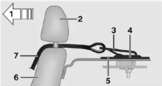
text_image
1 2 3 4 5 6 71 Direction of travel
2 Head restraint
3 Hook for upper retaining strap
4 Mounting point
5 Rear window shelf
6 Seat backrest
7 Upper retaining strap
Attaching the upper retaining strap to the mounting point
- Remove the mounting point cover.
- Raise the head restraint.
- Guide the upper retaining strap between the supports of the head restraint.
Guide it over the head restraint of the middle seat.
- Attach the hook of the retaining strap to the anchor.
- Tighten the retaining strap by pulling it down.
- Lower and lock head restraints as needed.
Locking the doors and windows in the rear
Doors
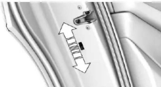
natural_image
Close-up of a door handle with a black clip and directional arrows indicating movement or force (no text or symbols)Push the locking lever on the rear doors up.
The door can now be opened from the outside only.
Safety switch for the rear
Press button on the driver's door if children are being transported in the
rear.
This locks various functions so that they cannot be operated from the rear: safety switch, refer to page 71.
Driving
Vehicle features and options
This chapter describes all standard, country-specific and optional features offered with the series. It also describes features that are not necessarily available in your car, e.g., due to the selected options or country versions. This also applies to safety-related functions and systems. The respectively applicable country provisions must be observed when using the respective features and systems.
Start/Stop button
The concept
Pressing the Start/Stop button switches drive readiness on or off.
Drive readiness starts with the brake pedal pressed when you
press the Start/Stop button.
Pressing the Start/Stop button again switches drive readiness back off and operating readiness, refer to page 19, is switched back on.
Drive readiness
Information

DANGER
If the exhaust pipe is blocked or ventilation is insufficient, harmful exhaust gases can enter into the vehicle. The exhaust gases contain carbon monoxide, an odorless and colorless but highly toxic gas. In enclosed areas, exhaust gases can also accumulate outside of the vehicle. There is danger to life. Keep the exhaust pipe free and ensure sufficient ventilation.

WARNING
An unsecured vehicle can put itself into motion and roll away. There is risk of an accident. Before exiting, secure the vehicle against rolling.
In order to ensure that the vehicle is secured against rolling away, observe the following:
▷ Set the parking brake.
On uphill grades or on a slope, turn the front wheels in the direction of the curb.
On uphill grades or on a slope, also secure the vehicle, e.g. with a wheel chock.

CAUTION
In the case of repeated starting attempts or repeated starting in quick succession, the fuel is not burned or is inadequately burned. The catalytic converter can overheat. There is risk of property damage. Avoid repeated starting in quick succession.
Switching on drive readiness
Steptronic transmission
- Depress the brake pedal.
- Press the Start/Stop button.
The ignition is activated automatically for a certain time and is stopped as soon as the engine starts.
Most of the indicator and warning lights in the instrument cluster light up for a varied length of time.
Switch off drive readiness
Steptronic transmission
- Engage selector lever position P with the vehicle stopped.
- Press the Start/Stop button.
The engine is switched off.
3. Set the parking brake.
Before driving into a car wash
So that the vehicle can roll into a car wash observe instructions for going into an automatic car wash, refer to page 291.
Auto Start/Stop function
The concept
The Auto Start/Stop function helps save fuel. The system switches off the engine during a stop, e.g., in traffic congestion or at traffic lights. Drive readiness remains switched on. The engine starts again automatically for driving off.
Information
After every engine start via the Start/Stop button, the Auto Start/Stop function is activated or deactivated, according to the last setting, refer to page 99. If the Auto Start/Stop function is active, it is available as soon as a speed of approx. 3 mph, approx. 5 km/h is exceeded.
Engine stop
The engine is switched off automatically during a stop under the following conditions:
The selector lever is in selector lever position D.
The brake pedal remains pressed while the vehicle is stationary or the vehicle is held by Automatic Hold.
The driver's safety belt is buckled or the driver's door is closed.
The air flow from the air conditioner is reduced when the engine is switched off.
Displays in the instrument cluster

The display in the tachometer indicates that the Auto Start/Stop function is ready for an Automatic engine start.
The display indicates that the conditions for an automatic engine stop have not been met.
Functional limitations
The engine is not switched off automatically in the following situations:
In case of a steep downhill grade.
▶ Brake not engaged strongly enough.
The external temperature is high and automatic climate control is running.
The car's interior has not yet been heated or cooled to the required level.
▶ If window condensation is imminent.
▶ Engine or other parts not at operating temperature.
▶ Engine cooling is required.
The wheels are at a sharp angle or the steering wheel is being turned.
▶ Vehicle battery is heavily discharged.
▶ At higher elevations.
The engine compartment lid is unlocked.
▶ HDC Hill Descent Control is activated.
The parking assistant is activated.
▶ Stop-and-go traffic.
▶ Selector lever position in N or R.
▶ After driving in reverse.
▶ Use of fuel with high ethanol content.
Starting the engine
The engine starts automatically under the following conditions:
▶ By releasing the brake pedal.
▶ When Automatic Hold is activated: press the accelerator pedal.
After the engine starts, accelerate as usual.
Safety mode
After the engine switches off automatically, it will not start again automatically if any one of the following conditions are met:
The driver's safety belt is unbuckled and the driver's door is open.
The hood was unlocked.
Some indicator lights light up for a varied length of time.
The engine can only be started via the Start/Stop button.
Functional limitations
Even if driving off was not intended, the deactivated engine starts up automatically in the following situations:
Excessive warming of the car's interior when the cooling function is switched on.
Excessive cooling of the car's interior when the heating is switched on.
▶ If window condensation is imminent.
The steering wheel is turned.
▶ Change from selector lever position D to N or R.
▶ Change from selector lever position P to N, D or R.
▶ Vehicle battery is heavily discharged.
▶ Start of an oil level measurement.
Activating/deactivating the system manually
Using the button
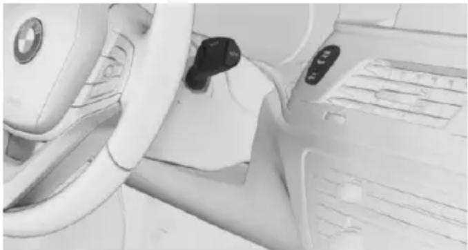
natural_image
Interior view of a car dashboard and steering wheel (no visible text or symbols)
Press button.
▶ LED comes on: Auto Start/Stop function is deactivated.
The engine is not automatically switched off.
The engine is started during an automatic engine stop.
The Auto Start/Stop function is deactivated in selector lever position M/S or in SPORT drive mode.
▶ LED goes out: Auto Start/Stop function is activated.
Switching off the vehicle during an automatic engine stop
During an automatic engine stop, the vehicle can be switched off permanently, e. g., when leaving it.
-
Press the Start/Stop button.
▶ Drive readiness is switched off.
▶ Operating readiness is switched on.
▶ Selector lever position P is engaged automatically. -
Set the parking brake.
Automatic deactivation
In certain situations, Auto Start/Stop function is deactivated automatically for safety reasons as if the driver were absent.
Malfunction
The Auto Start/Stop function no longer switches off the engine automatically. A Check Control message is displayed. It is possible to continue driving. Have the system checked.
Parking brake
The concept
The parking brake is used to prevent the vehicle from rolling when it is parked.
Information

WARNING
An unsecured vehicle can put itself into motion and roll away. There is risk of an accident. Before exiting, secure the vehicle against rolling.
In order to ensure that the vehicle is secured against rolling away, observe the following:
▷ Set the parking brake.
On uphill grades or on a slope, turn the front wheels in the direction of the curb.
On uphill grades or on a slope, also secure the vehicle, e.g. with a wheel chock.

WARNING
Unattended children or animals can move the vehicle and endanger themselves and traffic, e.g. with the following actions:
▶ Pressing the Start/Stop button.
▶ Releasing the parking brake.
▶ Opening and closing of doors or windows.
▶ Shifting the selector lever into neutral.
▶ Using vehicle equipment.
There is risk of accidents or injuries. Do not leave children or animals unattended in the vehicle. Carry remote control along when exiting and lock the vehicle.
Overview
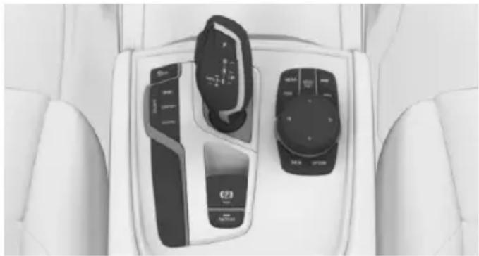
natural_image
Interior view of a car dashboard with two control switches and a touchscreen display (no visible text or symbols)
Parking brake
Setting

Pull the switch.
LED on the switch lights up.

The indicator lamp in the instrument cluster lights up red. The parking brake is set.
While driving
Use as emergency brake while driving:
Pull the switch and hold it. The vehicle brakes hard while the switch is being pulled.

The indicator lamp lights up red, a signal sounds and the brake lights light up.
A Check Control message is displayed.
If the vehicle is slowed down to a speed of approx. 2 mph/3 km/h the parking brake is set.
Releasing
With drive readiness switched on:

Press the switch while stepping on the brake pedal or selector lever position P is set.
The LED and indicator lamp go out.
The parking brake is released.
Automatic release
The parking brake is released automatically when you drive away.
The LED and indicator lamp go out.
Automatic Hold
The concept
This system assists the driver by automatically setting and releasing the brake, such as when moving in stop-and-go traffic.
The vehicle is automatically held in place when it is stationary.
On inclines, the system prevents the vehicle from rolling backward when driving off.
General information
Under the following conditions, the parking brake is automatically engaged:
▶ Drive readiness is deactivated.
The driver's door is opened while the vehicle is stationary.
The moving vehicle is brought to a standstill using the parking brake.

The indicator lamp changes from green to red.

The indicator lamp goes out.
Information

WARNING
An unsecured vehicle can put itself into motion and roll away. There is risk of an accident. Before exiting, secure the vehicle against rolling.
In order to ensure that the vehicle is secured against rolling away, observe the following:
▷ Set the parking brake.
On uphill grades or on a slope, turn the front wheels in the direction of the curb.
On uphill grades or on a slope, also secure the vehicle, e.g. with a wheel chock.

CAUTION
If the vehicle is stationary, Automatic Hold engages the parking brake. It prevents the vehicle from rolling in a car wash. There is risk of property damage. Deactivate Automatic Hold prior to entering the car wash.

WARNING
Unattended children or animals can move the vehicle and endanger themselves and traffic, e.g. with the following actions:
▶ Pressing the Start/Stop button.
▶ Releasing the parking brake.
▶ Opening and closing of doors or windows.
▶ Shifting the selector lever into neutral.
▶ Using vehicle equipment.
There is risk of accidents or injuries. Do not leave children or animals unattended in the vehicle. Carry remote control along when exiting and lock the vehicle.
Overview
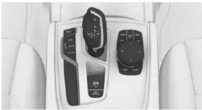
natural_image
Interior view of a car dashboard with two control panels and a touchscreen display (no visible text or symbols)
Automatic Hold
Establishing function readiness from Automatic Hold

Press the button while pressing on the brake pedal.
The LED on the button lights up.

The indicator lamp lights up green.
Automatic Hold is functional.
After every new vehicles start, the last selected setting is active.
Automatic Hold holding the vehicle
Function readiness is established.
After stepping on the brake pedal, e.g. when stopping at a traffic light, the vehicle is automatically secured against rolling.

The indicator lamp lights up green.
Step on the accelerator pedal to drive off.
The brake is released automatically.
The indicator lamp goes out.
Parking
The parking brake is engaged automatically if the vehicle is stopped with Automatic Hold and the drive-ready state is deactivated.

The indicator lamp changes from green to red.
The parking brake is not set if the drive-ready state is deactivated while the vehicle is coasting to a halt. Automatic Hold is deactivated.
Automatic Hold remains active during the engine stop brought about by the Auto Start/Stop function.
Switching function readiness off

Press button.
The LED on the button goes out.

The indicator lamp goes out.
Automatic Hold is switched off.
If the vehicle is being held by Automatic Hold, press on the brake pedal to switch it off.
Malfunction
In the event of a failure or malfunction of the parking brake, secure the vehicle against rolling using a wheel chock, e.g., when leaving it.
After a power failure
Putting the parking brake into operation
-
Turn on operations.
-
Pull the switch while stepping on the brake pedal or selector lever position P is set and then push.
It may take several seconds for the brake to be put into operation. Any sounds associated with this are normal.

The indicator lamp in the instrument cluster goes out as soon as the parking brake is ready for operation.
Turn signal, high beams, headlight flasher
Turn signal
Turn signal in exterior mirror
When driving and during operation of the turn signals or hazard warning system, do not fold in the exterior mirrors, so that the signal lights on the exterior mirror are easy to see.
Using turn signals
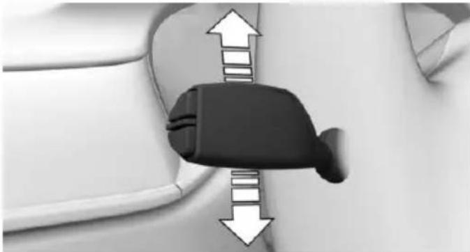
natural_image
Close-up of a car seatbelt buckle with directional arrows indicating movement (no text or symbols)Press the lever beyond the resistance point.
The turn signal lever returns into is starting position after actuation.
To switch off manually, slightly tap the lever to the resistance point.
Triple turn signal activation
Slightly tap lever.
The triple turn signal duration can be adjusted.
About iDrive:
- "My Vehicle"
- "Vehicle settings"
- "Lighting"
- "Exterior lighting"
- "One-touch turn signal"
- Select desired setting.
The setting is stored for the drive profile currently used.
Signaling briefly
Press the lever to the resistance point and hold it there for as long as you want the turn signal to flash.
High beams, headlight flasher
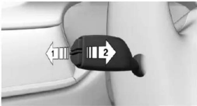
text_image
Diagram showing a car interior with two directional arrows labeled 1 and 2 pointing to a highlighted component.▷ High beams, arrow 1.
▶ High beams off/headlight flasher, arrow 2.
Washer/wiper system
Switching the wipers on/off and brief wipe
General information
Do not use the wipers if the windshield is dry, as this may damage the wiper blades or cause them to become worn more quickly.
Information

CAUTION
If the wipers are frozen to the windshield, the wiper blades can be torn off and the wiper motor overheat on switching on. There is risk of property damage. Defrost the windshield prior to switching the wipers on.
Switching on
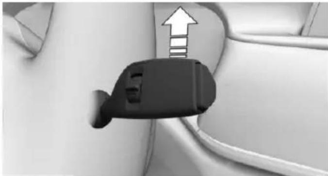
natural_image
Close-up of a car plug with an upward arrow indicating direction (no text or symbols)The lever automatically returns to its initial position when released.
▶ Normal wiper speed: tap up once.
The wipers switch to intermittent operation when the vehicle is stationary.
▶ Fast wiper speed: tap up twice or tap once beyond the resistance point.
Wipers change to normal speed when vehicle comes to standstill.
Switch off and brief wipe
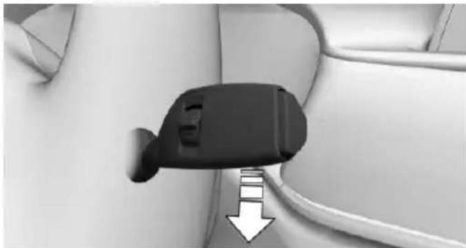
natural_image
Close-up of a black plastic clip attached to a white cable, with a white arrow pointing downward (no text or symbols visible)The lever automatically returns to its initial position when released.
▶ Single wipe: press down once.
To switch off from normal wiper speed: press down once.
To switch off from fast wiper speed: press down twice.
Intermittent operation or rain sensor
The concept
Without the rain sensor, the frequency of the wiper operation is preset.
The rain sensor automatically controls the time between wipes depending on the intensity of the rainfall. The sensor is located on the windshield, directly behind the interior rearview mirror.
Activating/deactivating
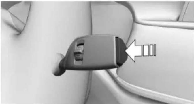
natural_image
Close-up of a car plug inserted into a seatbelt, with a white arrow pointing to the seat (no text or symbols visible)Press button on the wiper lever.
Wiping is started. If the vehicle is equipped with a rain sensor: LED in wiper lever lights up.
When wipers are frozen to windshield, wiper operation is deactivated.
During trip interruption with the rain sensor switched on: if the trip is resumed within approx. 15 minutes, the rain sensor is automatically activated again.

CAUTION
If the rain sensor is activated, the wipers can accidentally start moving in car washes. There is risk of property damage. Deactivate the rain sensor in car washes.
Setting the interval time or sensitivity of the rain sensor
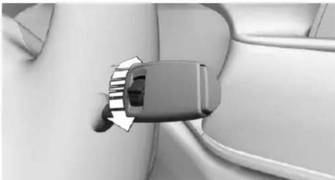
natural_image
Close-up of a car plug inserted into a cable socket (no visible text or symbols)Turn the thumbwheel to adjust the frequency or sensitivity of the rain sensor.
Up: short interval or high sensitivity of the rain sensor.
Down: long interval or low sensitivity of the rain sensor.
Clean the windshield, headlights
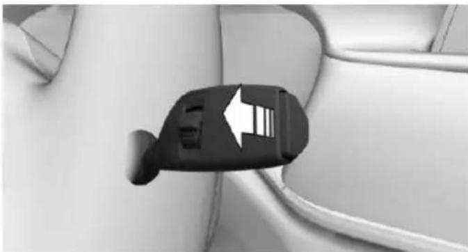
natural_image
Close-up of a car charging plug with a white arrow pointing to the plug (no text or symbols visible)Pull the wiper lever towards you.
The system sprays washer fluid on the wind-shield and activates the wipers briefly.
In addition, the headlights are cleaned at regular intervals when the vehicle's lights are activated.

WARNING
The washer fluid can freeze onto the window at low temperatures and obstruct the view. There is risk of an accident. Only use the washer systems, if the washer fluid cannot freeze. Use antifreeze if needed.

CAUTION
When the wiper water container is empty, the wash pump cannot work as intended. There is risk of property damage. Do not use the washer system when the wash water container is empty.
Windshield washer nozzles
The windshield washer nozzles are automatically heated while operating readiness is switched on.
Fold-out position of the wipers
Fold wipers back when you want to change the blades or with pending low temperatures.

WARNING
If the wipers start moving in the folded away state, damage may occur to parts of the vehicle or body parts can be jammed. There is risk of injuries or risk of property damage. Make sure that the vehicle is switched off when the wipers are in the folded away state and the wipers are folded in when switching on.
- Turn on operations.
- With icy conditions make sure that blades are not frozen to the windshield.
- Press and hold wiper lever downward, until the wipers stop in a close to vertical position.
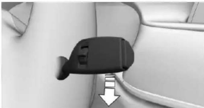
natural_image
Close-up of a black plug inserted into a cable, with a white arrow pointing to a cable outlet (no text or symbols visible)After the wipers are folded back down, the wiper system must be reactivated.
- Switch on drive readiness and press and hold the wiper lever downward again.
- Wipers return to their resting position and are ready again for operation.
Washer fluid
Information

WARNING
Some antifreeze agents can contain harmful substances and are flammable. There is risk of fire and risk of injuries. Observe the instructions on the containers. Keep antifreeze away from ignition sources. Do not refill operating materials into different bottles. Store operating materials out of reach of children.
United States: The washer fluid mixture ratio is regulated by the U.S. EPA and many individual states; do not exceed the allowable washer fluid dilution ratio limits that apply. Follow the usage instructions on the washer fluid container.
Use of BMW's Windshield Washer Concentrate or the equivalent is recommended.

WARNING
Improperly executed work under the hood can damage components and lead to a safety risk. There is risk of accidents or risk of property damage. Have work under the hood be executed by a dealer's service center or another qualified service center or repair shop.
Washer fluid reservoir
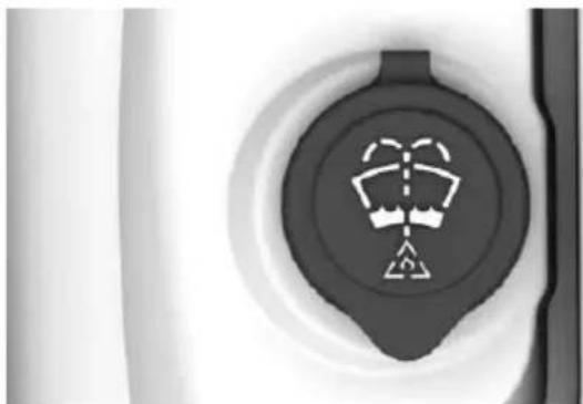
natural_image
Close-up of a circular mechanical component with a central symbol (no text or labels visible)
natural_image
Blank white image with no visible content, text, or symbolsAll washer nozzles are supplied from one reservoir in the engine compartment.
Fill with a mixture of windshield washer concentrate and tap water and – if required – with a washer antifreeze, according to the manufacturer's recommendations.
Mix the washer fluid before adding to find the right mixture.
Do not add windshield washer concentrate and antifreeze undiluted and do not fill with pure water; this could damage the wiper system.
Do not mix window washer concentrates of different manufacturers because they can clog the windshield washer nozzles.
Recommended minimum fill quantity: 0.2 US gal/1 liter.
Steptronic transmission
Information

WARNING
An unsecured vehicle can put itself into motion and roll away. There is risk of an accident. Before exiting, secure the vehicle against rolling.
In order to ensure that the vehicle is secured against rolling away, observe the following:
▷ Set the parking brake.
On uphill grades or on a slope, turn the front wheels in the direction of the curb.
On uphill grades or on a slope, also secure the vehicle, e.g. with a wheel chock.
Selector lever positions
D Drive
Selector lever position for normal vehicle operation. All gears for forward travel are activated automatically.
To reduce fuel consumption, the engine is automatically decoupled from the transmission under the conditions described for Coasting, refer to page 245.
R is Reverse
Select only when the vehicle is stationary.
N Neutral:
The vehicle may roll in selector lever position N.
Engage selector lever position N, e.g. in car washes, refer to page 291.
With operating readiness switched off, refer to page 20, selector lever position P is engaged automatically.
P Park
Select only when the vehicle is stationary. The drive wheels are blocked.
Selector lever position P is engaged automatically:
▶ After drive readiness, refer to page 97, is switched off and selector lever position R or D is engaged.
▶ If operating readiness is switched off and selector lever position N is engaged.
If the driver's safety belt is released, the driver's door is opened, and the brake pedal is not pressed while the vehicle is stationary and selector lever position D or R is set.
Kickdown
Kickdown is used to achieve maximum driving performance. Step on the accelerator pedal beyond the resistance point at the full throttle position.
Engaging selector lever positions
General information
To prevent the vehicle from creeping after you select a gear, maintain pressure on the brake pedal until you are ready to start.
It is not possible to shift out of selector lever position P until the engine is running and the brake is applied.
With the vehicle is stationary, press on the brake pedal before shifting out of selector lever position P or N; otherwise, the shift command will not be executed: shift lock.
A block prevents the inadvertent switching to selector lever position R or the inadvertent change from selector lever position P.
Engaging selector lever position D, N, R
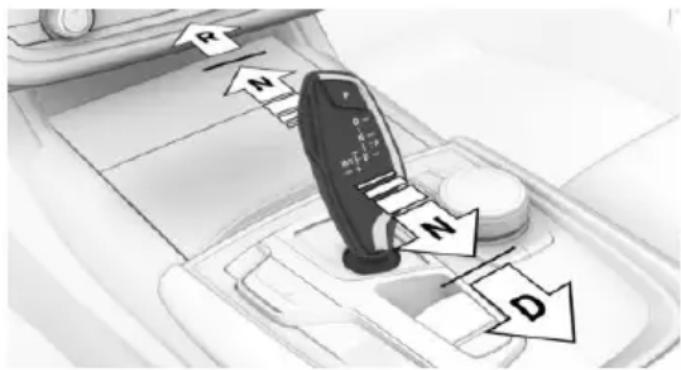
text_image
R N F 0 + - m1+2 D N DBriefly push the selector lever in the desired direction, beyond a resistance point if needed.
After releasing the selector lever, it returns to its center position.
Canceling the lock
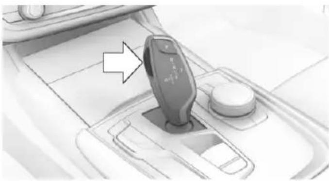
natural_image
Interior view of a car dashboard with a smartwatch and control panel (no visible text or symbols)Press unlock button.
Engage selector lever position P
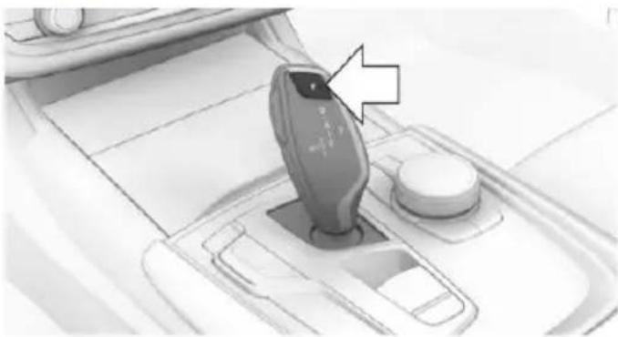
natural_image
Interior view of a car dashboard with a hand cursor pointing to the left side (no visible text or symbols)Press button P.
Sport program and manual mode
Activating the sport program
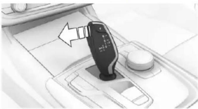
natural_image
Diagram of a car gear shift lever with a black sensor and directional arrow (no text or symbols)Press the selector lever to the left out of selector lever position D.
The engaged gear is displayed in the instrument cluster, e.g., S1.
The sport program of the transmission is activated.
Activating the M/S manual mode
-
Press the selector lever to the left out of selector lever position D.
-
Push the selector lever forward or pull it backward.
Manual mode becomes active and the gear is changed.
The engaged gear is displayed in the instrument cluster, e.g., M1.
If the situation requires, the Steptronic transmission continues to shift automatically.
Example: once maximum engine speed is attained, M/S manual mode is automatically upshifted as needed.
Switching to manual mode
To shift down: press the selector lever forward.
To shift up: pull the selector lever rearwards.
Gears will only be shifted at appropriate engine and road speeds, for example downshifting is not possible if the engine speed is too high.
The selected gear is briefly displayed in the instrument cluster, followed by the currently selected gear.
Steptronic Sport transmission: prevent automatic upshifting in M/S manual mode
If drive mode SPORT, refer to page 111, is selected, the Steptronic Sport transmission does not automatically upshift in M/S manual mode once the maximum speed is reached.
In addition, there is no downshift for kickdown.
With the respective transmission version, the lowest possible gear can be selected by simultaneously operating the kickdown and the left shift paddle. However, this effect is not produced via the shift paddles when switching briefly from selector lever position D to manual mode.
Ending the sport program/manual mode
Push the selector lever to the right.
D is displayed in the instrument cluster.
Shift paddles
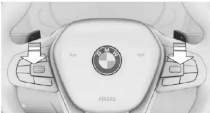
natural_image
Top-down view of a BMW car's steering wheel with labeled buttons and brand logo (no readable text beyond branding)The shift paddles on the steering wheel allow you to shift gears quickly while keeping both hands on the steering wheel.
▶ Shift up: briefly pull right shift paddle.
▶ Shift down: briefly pull left shift paddle.
▶ With the respective transmission version, the lowest possible gear can be selected by pulling and holding the left shift paddle.
Gears will only be shifted at appropriate engine and road speeds, for example downshifting is not possible if the engine speed is too high.
The selected gear is briefly displayed in the instrument cluster, followed by the current gear.
If the shift paddles on the steering wheel are used to shift gears in automatic mode, the transmission temporarily switches to manual mode.
If the selector lever is still in selector lever position D with the respective transmission version, it is possible to switch back into the automatic mode:
▶ Pull and hold right shift paddle.
or
In addition to the briefly pulled right shift paddle, briefly pull the left shift paddle.
In the manual mode, after conservative driving for a certain amount of time or if there has
been no acceleration or shifting of the shift paddles within a certain amount of time, the transmission switches back to automatic mode.
Displays in the instrument cluster

The selector lever position is displayed, e.g.: P.
Electronic unlocking of the transmission lock
General information
Electronically unlock the transmission lock to maneuver vehicle from the danger area.
Unlocking is possible, if the started can spin the engine.
Engaging selector lever position N
- Depress the brake pedal.
- Press and hold the Start/Stop button. The starter must audibly start.
- Press and hold the selector lever into selector lever position N, until selector lever position N is displayed in the instrument cluster.
A corresponding Check Control message is displayed. - Release Start/Stop button and selector lever.
- Release brake, as soon as the starter stops.
- Maneuver the vehicle from the danger area and secure it against moving on its own.
Launch Control
The concept
Launch Control enables optimum acceleration on surfaces with good traction.
General information
The use of Launch Control causes premature component wear since this function represents a very heavy load for the vehicle.
Do not use Launch Control during the break-in, refer to page 234, period.
To increase vehicle stability, activate DSC again as soon as possible.
An experienced driver may be able to achieve better acceleration values in DSC OFF mode.
Requirements
Launch Control is available when the engine is warmed up, that is, after uninterrupted driving of at least 6 miles/10 km.
To start with Launch Control do not steer the steering wheel.
Start with launch control
While the engine is running:
- Press button.
TRACTION is displayed in the instrument cluster and the indicator lamp for DSC OFF lights up.
-
Engage selector lever position S.
-
With the left foot, forcefully press down on the brake.
-
Press and hold down the accelerator pedal beyond the resistance point at the full throttle position, kickdown.
A flag symbol is displayed in the instrument cluster.
- The starting engine speed adjusts. Within 3 seconds, release the brake.
Before using Launch Control, allow the transmission to cool down for approx. 5 minutes.
Launch Control adjusts to the surrounding conditions, e.g., wet pavement, when used again.
Driving Dynamics Control
The concept
The Driving Dynamics Control influences the driving dynamics properties of the vehicle. The vehicle can be adjusted depending on the situation using various driving modes.
The following systems are affected:
▶ Engine characteristics.
▶ Steptronic transmission.
▷ Dynamic Damping Control.
Air suspension
Active roll stabilization.
▶ Integral Active Steering.
▷ Display in the instrument cluster.
▶ Cruise control.
▶ Backrest width for comfort seats.
Overview
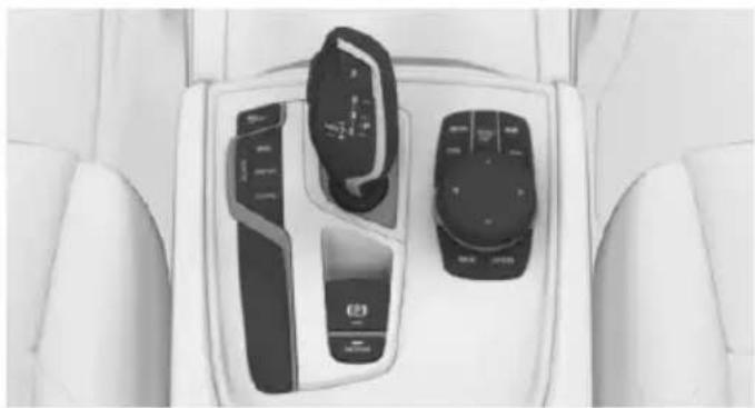
natural_image
Interior view of a car dashboard with two control switches and a display case (no visible text or symbols)Controls
Drive modes
Press button Drive mode Configuration
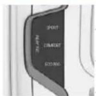
text_image
SPORT COMMERCIAL STANDINGSPORT INDIVIDUAL
COMFORT PLUS
ECO PRO INDIVIDUAL
ADAPTIVE
Selecting a driving mode
Press button for the desired driving mode once.
Activating configuration of the driving mode
Press button for the desired driving mode several times.
Configure INDIVIDUAL driving mode
- Activate desired driving mode with Driving Dynamics Control switch.
- "Configure INDIVIDUAL"
Select desired setting.
The individual configuration of the driving mode is taken over for the active profile. The last set configuration is activated directly when the driving mode is called up. With activating of the drive-ready state, the COMFORT driving mode is selected automatically.
Displays in the instrument cluster
SPORT
The selected drive mode is displayed in the instrument cluster.
Display on the Control Display
Drive mode changes can be briefly shown on the Control Display.
About iDrive:
- "My Vehicle"
- "Vehicle settings"
- "Driving Experience Control"
- "Driving mode information in control display"
Driving modes in detail
COMFORT
The concept
Balanced tuning between dynamic and consumption-optimized driving.
Switching on
Press button repeatedly until COM-FORT is displayed in the instrument
cluster.
COMFORT PLUS
The concept
Particularly comfortable tuning for optimum traveling comfort.
Switching on

Press button repeatedly until COM- FORT PLUS is displayed in the instru-
ment cluster.
SPORT
The concept
Dynamic tuning for higher agility.
Switching on
Press button. SPORT is displayed in the instrument cluster.
SPORT INDIVIDUAL
The concept
Individual settings can be adjusted in the SPORT INDIVIDUAL drive mode.
Configuration
About iDrive:
- "My Vehicle"
- "Vehicle settings"
- "Driving Experience Control"
- "Configure SPORT INDIVIDUAL"
- Select desired setting.
The setting is stored for the drive profile currently used.
Reset SPORT INDIVIDUAL to the standard settings:
"Reset to SPORT STANDARD".
ECO PRO
The concept
Consumption-optimized tuning, refer to page 241.
Switching on

Press button. ECO PRO is displayed in the instrument cluster.
ECO PRO INDIVIDUAL
The concept
Individual settings can be adjusted in the ECO PRO INDIVIDUAL drive mode.
Configuration
About iDrive:
- "My Vehicle"
- "Vehicle settings"
- "Driving Experience Control"
- "Configure ECO PRO INDIVIDUAL"
- Select desired setting.
The setting is stored for the drive profile currently used.
Reset ECO PRO INDIVIDUAL to the standard settings:
"Reset to ECO PRO STANDARD".
ADAPTIVE
The concept
Comfort-oriented drive mode, whose tuning is automatically adjusted to the driving situation and driving style.
If the navigation system is active, upcoming road sections are considered as well.
Switching on

Press button. ADAPTIVE is displayed in the instrument cluster.
Displays
Vehicle features and options
This chapter describes all standard, country-specific and optional features offered with the series. It also describes features that are not necessarily available in your car, e. g., due to
the selected options or country versions. This also applies to safety-related functions and systems. The respectively applicable country provisions must be observed when using the respective features and systems.
Instrument cluster
The concept
The instrument cluster is a variable display. In the event of a program change, the display rendition adapts to the respective program through the Driving Dynamics Control. The change of the display type can be deactivated via iDrive.
Some of the displays in the instrument cluster may differ from the way they are shown in this Owner's Manual.
Overview
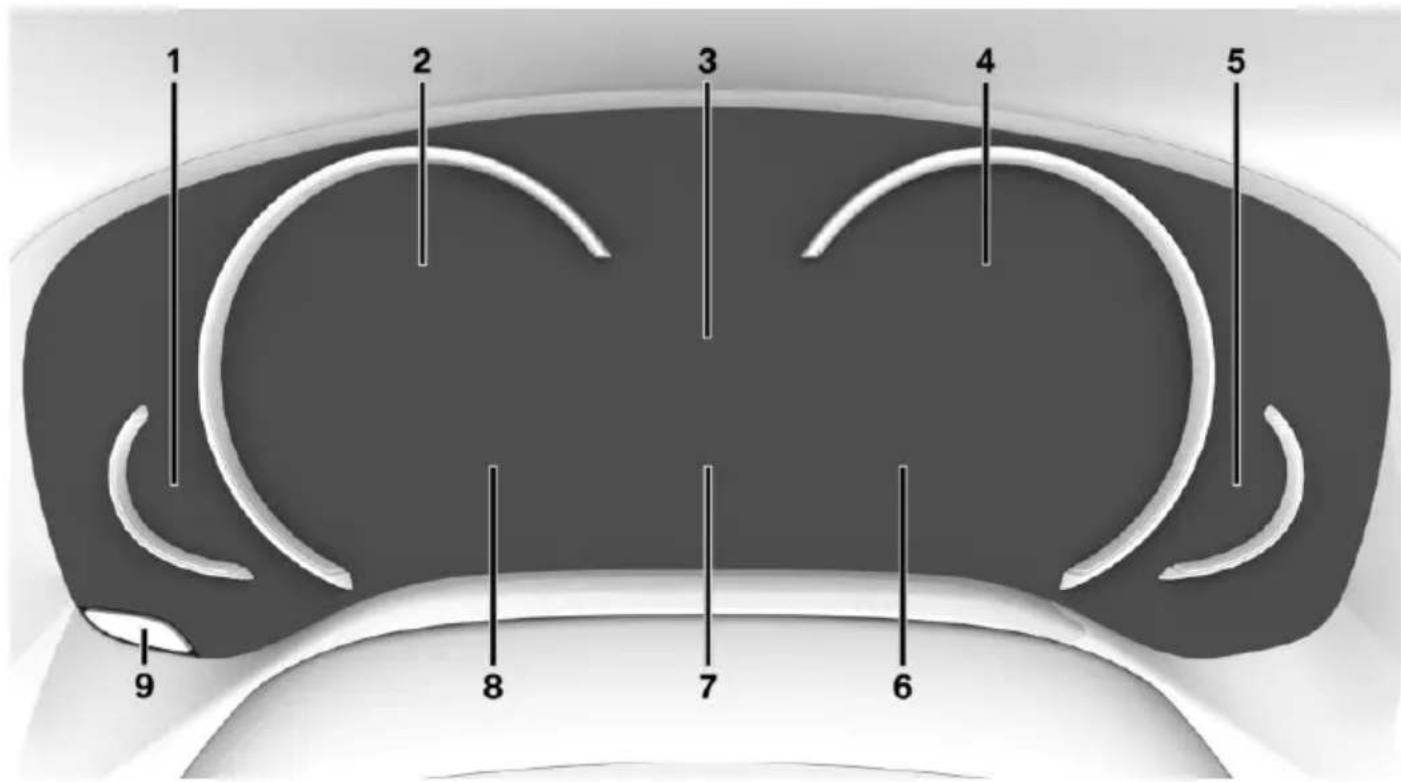
text_image
1 2 3 4 5 9 8 7 61 Fuel gauge 118
2 Speedometer
3 Time 118
External temperature 118
Driver assistance system displays
4 Tachometer 118
Selection lists 121
ECO PRO displays 241
Navigation display
Messages, e.g., Check Control
5 Engine temperature 118
6 Transmission display 106
Status, Driving Dynamics Control 110
Adjusting the view
The concept
In addition to the driving program views, the instrument cluster can be adjusted to three different operating modes.
Adjusting
About iDrive:
- "My Vehicle"
- "System settings"
- "Displays"
- "Instrument panel"
- Select desired setting.
▶ "STANDARD": All displays on the instrument cluster are active.
▶ "REDUCED" All displays on the instrument cluster are reduced to the essential.
▶ "INDIVIDUAL": All displays on the instrument cluster are active. Individual displays can be individually configured.
Individual view
▶ "Driving mode display": when the driving program is switched into ECO PRO or SPORT, the instrument cluster automatically switched into the respective view.
▶ "Traffic sign detection Speed Limit Info": the traffic signs and additional signs recognized via speed limit detection are displayed.
7 On-board computer 122
8 Driver assistance system displays
Speed limit detection 120
9 Reset miles 123
▶ "Speed limit exceeded": if the speed recognized by speed limit detection is exceeded, the exceeded range is marked red in the speedometer.
▶ Instrument cluster with enhanced features: "Magnifier function": the current speed is shown enlarged in the speedometer.
Check Control
The concept
The Check Control system monitors functions in the vehicle and notifies you of malfunctions in the monitored systems.
A Check Control message is displayed as a combination of indicator or warning lights and text messages in the instrument cluster and in the Head-up Display.
In addition, an acoustic signal may sound and a text message may appear on the Control Display.
Indicator/warning lights
General information
The indicator and warning lights in the instrument cluster can light up in a variety of combinations and colors.
Several of the lamps are checked for proper functioning and light up temporarily when drive readiness is switched on.
Red lights
Safety belt reminder

Flashing or illuminated: safety belt on the driver or passenger side is not buckled. The safety belt reminder can also be activated if objects are placed on the front passenger seat.
Make sure that the safety belts are positioned correctly.
Airbag system

Airbag system and belt tensioner are not working.
Have the vehicle checked immediately by a dealer's service center or another qualified service center or repair shop.
Parking brake

The parking brake is set.
For additional information, refer to Release parking brake, refer to page 100.
Brake system

Braking system disrupted. Continue to drive moderately.

Have the vehicle checked immediately by a dealer's service center or another qualified service center or repair shop.
Yellow lights
Anti-lock Braking System ABS

Avoid sudden braking as much as possible. Braking force boost may not be working. Stop cautiously. Take into account the longer brake distance. Have checked immediately by a dealer's service center or another qualified service center or repair shop.
DSC Dynamic Stability Control

Flashing: DSC controls the drive and braking forces. The vehicle is stabilized. Reduce speed and adapt driving style to the driving circumstances.
Illuminated: DSC failed. Have system checked immediately by a dealer's service center or another qualified service center or repair shop.
For additional information, refer to Dynamic Stability Control DSC, refer to page 163.
DSC Dynamic Stability Control is deactivated or DTC Dynamic Traction Control is activated

Dynamic Stability Control DSC is switched off or Dynamic Traction Control DTC is switched on.
For additional information, refer to Dynamic Stability Control DSC, refer to page 163, and Dynamic Traction Control DTC, refer to page 164.
Flat Tire Monitor FTM

The Flat Tire Monitor signals a loss of tire inflation pressure in a tire.
Reduce your speed and stop cautiously. Avoid sudden braking and steering maneuvers.
For more information, see Flat Tire Monitor, refer to page 268.
Tire Pressure Monitor TPM

Illuminated: the Tire Pressure Monitor signals a loss of tire inflation pressure in a tire.
Reduce your speed and stop cautiously. Avoid sudden braking and steering maneuvers.
Flashing and then continuously illuminated: no flat tire or loss of tire inflation pressure can be detected.
▶ Interference through systems or devices with the same radio frequency: After leaving the area of the interference, the system automatically becomes active again.
▷ TPM could not conclude the reset: perform the reset of the system again.
A wheel without TPM electronics is mounted: Have it checked by a dealer's service center or another qualified service center or repair shop as needed.
Malfunction: Have system checked immediately by a dealer's service center or another qualified service center or repair shop.
For more information, see Tire Pressure Monitor, refer to page 264.
Steering system

Steering system in some cases not working.
Have steering system checked immediately by a dealer's service center or another qualified service center or repair shop.
Engine functions

Engine function disturbed. Have vehicle checked immediately by a dealer's service center or another qualified service center or repair shop.
For additional information, refer to On-board Diagnostics socket, refer to page 280.
Green lights
Turn signal

Turn signal switched on.
Unusually rapid flashing of the indicator lamp indicates that a turn signal bulb
has failed.
For additional information, refer to Turn signal, refer to page 103.
Parking lights, headlight control

Parking lights or headlights are activated.
For additional information, refer to Parking lights/low beams, headlight control, refer to page 129.
Lane departure warning

The system is activated. At least one lane marking was detected and warnings can be issued.
For additional information, refer to Lane departure warning, refer to page 150.
Front fog lights

Front fog lights are activated.
For additional information, refer to Front fog lights, refer to page 132.
High-beam Assistant

High-beam Assistant is switched on.
High beams are activated and off automatically as a function of the traffic sit-
For additional information, refer to High-beam Assistant, refer to page 132.
Automatic Hold

Function is activated. The vehicle is automatically held in place when it is stationary.
For more information, see Automatic Hold, refer to page 101.
Blue lights
High beams

High beams are activated.
For additional information, refer to High beams, refer to page 103.
General lamps
Check Control

At least one Check Control message is displayed or is stored.
Text messages
Text messages in combination with a symbol in the instrument cluster explain a Check Control message and the meaning of the indicator and warning lights.
Supplementary text messages
Additional information, such as on the cause of an error or the required action, can be called up via Check Control.
With urgent messages the added text will be automatically displayed on the Control Display.
Functions
Depending on the Check Control message, the following functions can be selected.
▶ "Owner's Manual"
Display additional information about the Check Control message in the Integrated Owner's Manual.
▶ "Service request"
Contact a dealer's service center or another qualified service center or repair shop.
▶ "BMW Roadside Assistance"
Contact Roadside Assistance.
Hiding Check Control messages
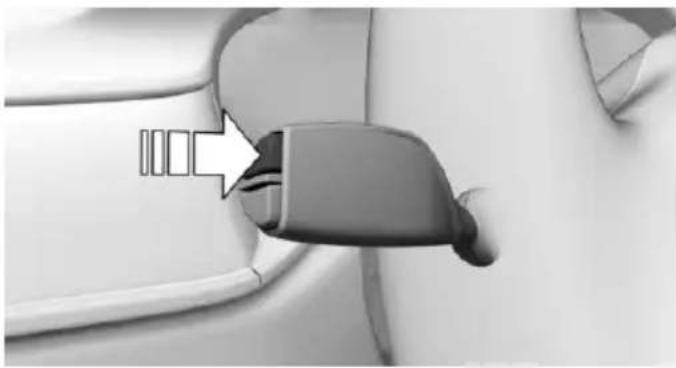
natural_image
Close-up of a car seatbelt switch with a white arrow pointing to the grip (no text or symbols visible)Press and hold PC button on blinker lever.
Some Check Control messages are displayed continuously and are not cleared until the malfunction is eliminated. If several malfunctions occur at once, the messages are displayed consecutively.
These messages can be faded for approx. 8 seconds. After this time, they are displayed again automatically.
Other Check Control messages are faded automatically after approx. 20 seconds. They are stored and can be displayed again later.
Displaying stored Check Control messages
About iDrive:
- "My Vehicle"
- "Vehicle status"
- "Check Control"
- Select the text message.
Messages after trip completion
Special messages displayed while driving are displayed again after the drive readiness is switched off.
Fuel gauge
Instrument cluster
Vehicle tilt position may cause the display to vary.
An arrow beside the fuel pump symbol shows which side of the vehicle the fuel filler flap is on.
Hints on refueling, refer to page 250.
Instrument cluster with enhanced features
Vehicle tilt position may cause the display to vary.
The current range is also displayed as numerical value.
An arrow beside the fuel pump
symbol shows which side of the vehicle the fuel filler flap is on.
Hints on refueling, refer to page 250.
Tachometer
Always avoid engine speeds in the red warning field. In this range, the fuel supply is interrupted to protect the engine.
Operating readiness and drive readiness
The letters OFF on the tachometer indicate that the drive readiness is switched off and operating readiness is switched on.

The letters READY in the tachometer indicate that the vehicle is ready for driving.
Further information, see Idle state, operating and drive readiness, refer to page 19.
Engine temperature
▶ Cold engine: the pointer is at the low temperature end. Drive at moderate engine and vehicle speeds.
Normal operating temperature: the pointer is in the middle or in the lower half of the temperature display.
Hot engine: the pointer is at the high end of the temperature range. A Check Control message is also displayed.
Check the coolant level, refer to page 277.
External temperature
If the indicator drops to +37 °F/+3 °C or lower, a signal sounds.
A Check Control message is displayed.
There is an increased risk of ice on roads.

WARNING
Even at temperatures above +37 °F/+3 °C there can be a danger of icy roads, e.g. on bridges or shady sections of road. There is risk of an accident. Adjust your driving style to the weather conditions at low temperatures.
Time
The time is displayed in the instrument cluster. Setting the time and time format, refer to page 38.
Service requirements
The concept
After switching on the drive-ready state, the instrument cluster briefly displays available driving distance or time to the next scheduled maintenance.
A service advisor can read out the current service requirements from your remote control.
Some information regarding the service requirements can also be shown on the remote control with display.
Display
Detailed information on service requirements
More information on the scope of service required can be displayed on the Control Display.
About iDrive:
- "My Vehicle"
- "Vehicle status"
- "Service required"
Required maintenance procedures and legally mandated inspections are displayed. - Select an entry to call up detailed information.
Symbols
Symbols
Description

No service is currently required.

The deadline for scheduled maintenance or a legally mandated inspection is approaching.

The service deadline has already passed.
Entering appointment dates
Enter the dates for the required inspections.
Make sure that the vehicle's date and time are set correctly.
About iDrive:
- "My Vehicle"
- "Vehicle status"
- "Service required"
- "Vehicle inspection"
- "Date:"
- Select desired setting.
- Confirm.
The entered date is stored.
Automatic Service Request
Data regarding the service status or legally mandated vehicle inspections are automatically transmitted to your dealer's service center before a service due date.
You can check when your dealer's service center was notified.
About iDrive:
- "My Vehicle"
- "Vehicle status"
- "Service Request"
Gear shift indicator
The concept
The system recommends the most fuel efficient gear for the current driving situation.
General information
Depending on the vehicle's features and country version of the vehicle, the gear shift indicator is active in the manual mode of the Steptronic transmission.
Suggestions to shift gear up or down are displayed in the instrument cluster.
On vehicles without a gear shift indicator, the engaged gear is displayed.
Displays
Example Description

Fuel efficient gear is set.

Shift into fuel efficient gear.
Speed limit detection
The concept
Speed limit detection
Speed limit detection shows the current maximum permitted speed in the instrument cluster. The camera in the area of the interior rearview mirror detects traffic signs at the edge of the road as well as variable overhead sign posts. Traffic signs with extra symbols for wet road conditions, etc. are also detected and compared with the vehicle's onboard data, such as for the rain sensor, and will be displayed depending on the situation. The system takes into account the information stored in
the navigation system and also displays speed limits present on routes without signs.
Information

WARNING
The system does not relieve from the personal responsibility to correctly assess visibility and traffic situation. There is risk of an accident. Adjust the driving style to the traffic conditions. Watch traffic closely and actively interfere in the respective situations.
Overview
Camera
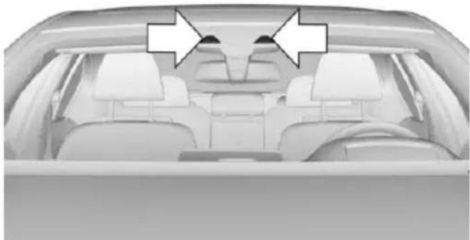
natural_image
Interior view of a car showing rear seats and dashboard (no visible text or symbols)The camera is installed near the interior rear-view mirror.
Keep the windshield in the area behind the interior rearview mirror clean and clear.
Switching on/off
About iDrive:
-
"My Vehicle"
-
"System settings"
-
"Displays"
-
"Instrument panel"
-
"INDIVIDUAL"
-
"Traffic sign detection Speed Limit Info" If speed limit detection is switched on, it is shown in the instrument cluster.
Display
The following is displayed in the instrument cluster:
Speed limit detection
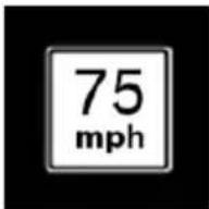
Current speed limit.

Speed limit detection is not available.
Speed limit detection can also be displayed in the Head-up Display.
System limits
The system may not be fully functional and may provide incorrect information in the following situations:
In heavy fog, rain or snowfall.
When signs are concealed by objects.
▷ When driving very close to the vehicle in front of you.
When driving toward bright lights.
When the windshield behind the interior rearview mirror is fogged over, dirty or covered by a sticker, etc.
In the event of incorrect detection by the camera.
▶ If the speed limits stored in the navigation system are incorrect.
In areas not covered by the navigation system.
When roads differ from the navigation, such as due to changes in road routing.
When passing buses or trucks with a speed sticker.
▶ If the traffic signs are non-conforming.
During calibration of the camera immediately after vehicle delivery.
Selection lists in the instrument cluster
The concept
Depending on your vehicle's equipment, the following can be displayed or operated using the buttons and the thumbwheel on the steering wheel as well as the displays in the instrument cluster and the Head-up Display:
▶ Current audio source.
▶ Redial phone feature.
▶ Turn on voice activation system.
Display
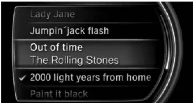
text_image
Lady Jane Jumpin'jack flash Out of time The Rolling Stones ✓ 2000 light years from home Paint it blackDepending on your vehicle's optional features, the list in the instrument cluster can differ from the illustration shown.
Activating a list and adjusting the setting
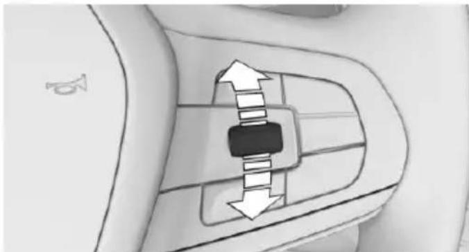
natural_image
Diagram of a mechanical component with directional arrows indicating movement or force (no text or symbols)On the right side of the steering wheel, turn the thumbwheel to activate the corresponding list.
Using the thumbwheel, select the desired setting and confirm it by pushing the thumbwheel.
On-board computer in the instrument cluster
Display
The information from the on-board computer is shown in the instrument cluster.
Calling up information
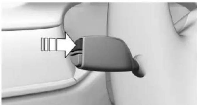
natural_image
Close-up of a car seatbelt buckle with a white arrow pointing to the buckle (no text or symbols visible)Press and hold PC button on blinker lever.
The respective information is displayed in the instrument cluster.
Information at a glance
Repeatedly pressing the button on the turn signal lever calls up the following information in the instrument cluster:
- Miles and trip miles. - Bar display for energy recovery and current fuel consumption.
▶ Bar display for range.
▶ Average fuel consumption and average speed.
Time of arrival and distance to destination. When destination guidance is activated in the navigation system.
In ECO PRO mode: bonus range.
▶ Digital speed.
Adjusting displays for on-board computer
For several displays of the on-board computer, it is possible to set whether they can be called up in the instrument cluster.
About iDrive:
- "My Vehicle"
- "System settings"
- "Displays"
- "Instrument panel"
- "Onboard info"
- Select desired setting.
Information in detail
Odometer and trip odometer
Display
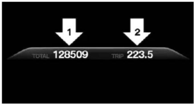
bar
| Category | Value | |---|---| | 1 | 128509 | | 2 | 223.5 |▶ Odometer, arrow 1.
▶ Trip odometer, arrow 2.
Display/reset miles

natural_image
Close-up of a white object with curved lines and a dark spot, possibly part of a surface or abstract design (no text or symbols visible)Press the knob.
▶ With drive readiness switched off, time, external temperature and odometer are displayed.
When drive readiness is switched on, the trip odometer is reset.
Energy recovery and current fuel consumption
The concept
Energy recovery and current fuel consumption can be displayed as bar displays in the on-board computer.
Display
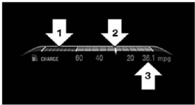
text_image
1 2 3 CHARGE 60 40 20 36.1 mpg▶ Energy recovery, arrow 1.
▶ Current fuel consumption, arrow 2.
▶ Average consumption, arrow 3.
Energy recovery
The kinetic energy of the vehicle is converted into electric energy during coasting (overrun) mode. The vehicle battery is partially charged and fuel consumption can be reduced.
Current fuel consumption
The current fuel consumption displays the current consumption of fuel. Check whether you are currently driving in an efficient and environmentally-friendly manner.
Range
The concept
Current range and total range can be displayed as bar displays in the onboard computer.
Display
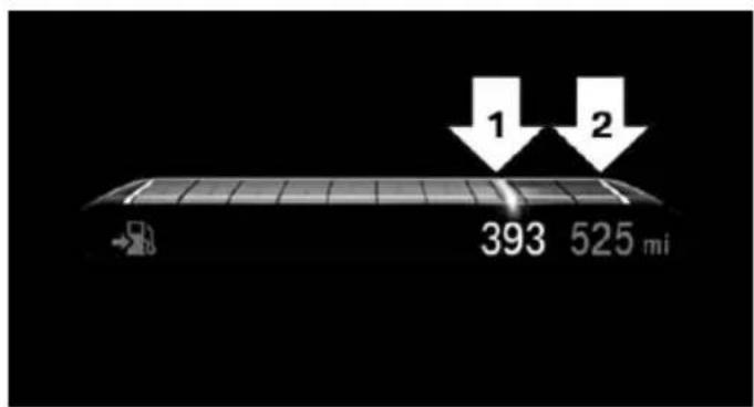
text_image
1 2 393 525 mi▶ Current range, arrow 1.
▶ Total range, arrow 2.
With a low remaining range, a Check Control message is briefly displayed. With a dynamic driving style, e.g. taking curves aggressively, the engine function is not always ensured.
The Check Control message appears continuously below a range of approx. 30 miles/50 km.

CAUTION
With a range of less than 30 miles/50 km it is possible that the engine will no longer have sufficient fuel. Engine functions are no longer ensured. There is risk of property damage. Refuel promptly.
Average speed and average fuel consumption
General information
Average speed and average fuel consumption are calculated for the distance traveled since the last reset in the onboard computer.
Periods in which the vehicle is parked with the engine manually stopped are not included in the calculation of the average speed.
Display
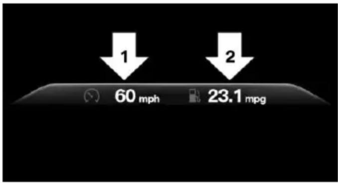
text_image
1 2 60 mph 23.1 mpg▶ Average speed, arrow 1.
▶ Average consumption, arrow 2.
Resetting average values
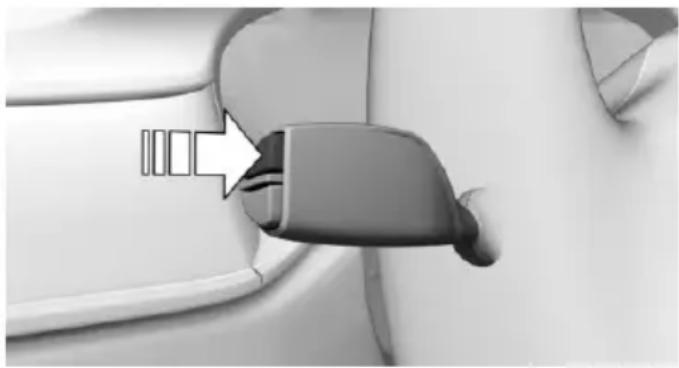
natural_image
Close-up of a car seatbelt buckle with a white arrow pointing to the seat (no text or symbols visible)Press and hold PC button on blinker lever.
Time of arrival and distance to destination
The concept
The estimated time of arrival and the distance remaining to the destination are displayed if a destination is entered in the navigation system before the trip is started. A correctly adjusted clock is a prerequisite for a correct time of arrival.
Display
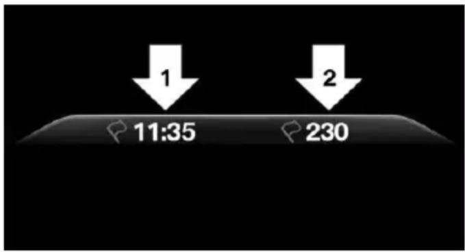
text_image
1 11:35 2 230▶ Time of arrival, arrow 1.
▷ Distance to destination, arrow 2.
ECO PRO bonus range
In the ECO PRO mode, the ECO PRO bonus range, refer to page 243, can be displayed in the instrument cluster.
Onboard computer on the Control Display
General information
Two types of onboard computers are available on the Control Display:
▶ "Onboard info": the values can be reset as often as necessary.
▶ "Trip computer": the values provide an overview of the current trip.
Calling up the onboard computer or trip computer
About iDrive:
- "My Vehicle"
- "Driving information"
- "Onboard info" or "Trip computer"
Resetting the trip on-board computer
About iDrive:
- "My Vehicle"
- "Driving information"
-
"Trip computer"
-
▷ "Reset": all values are reset.
▶ "Automatic reset": all values are reset approx. 4 hours after the vehicle came to a standstill.
Resetting the fuel consumption or speed
About iDrive:
- "My Vehicle"
- "Driving information"
- "Onboard info"
- "Consumption" or "Speed"
- "OK"
Sport displays
The concept
On the Control Display, the current values for performance and torque can be displayed if the vehicle is appropriately equipped.
Displaying sport displays on the Control Display
About iDrive:
- "My Vehicle"
- "Technology in action"
- "Sport displays"
Speed warning
The concept
Displays a speed, when reached, should cause a warning to be issued.
The warning is repeated if the vehicle speed drops below the set speed once by at least 3 mph/5 km/h.
Displaying, setting or changing the speed warning
About iDrive:
- "My Vehicle"
- "Vehicle settings"
- "Speed warning"
- "Warning at:"
- Turn the controller until the desired speed is displayed.
- Press the controller.
Speed warning is stored.
Activating/deactivating the speed warning
About iDrive:
- "My Vehicle"
- "Vehicle settings"
- "Speed warning"
- "Speed warning"
- Press the controller.
Setting your current speed as the speed warning
About iDrive:
- "My Vehicle"
- "Vehicle settings"
- "Speed warning"
- "Select current speed"
- Press the controller.
The current vehicle speed is stored as the speed warning.
Vehicle status
The concept
The status can be displayed and actions performed for several systems.
Opening the vehicle status
About iDrive:
- "My Vehicle"
- "Vehicle status"
Information at a glance
"Flat Tire Monitor": Status of the Flat Tire Monitor, refer to page 269.
▶ "Tire Pressure Monitor": Status of the Tire Pressure Monitor, refer to page 265.
▶ Reset the Tire Pressure Monitor, refer to page 265.
Engine oil level"Electronic engine oil level check, refer to page 273.
▶ "Check Control": Display of stored Check Control messages, refer to page 117.
"Service required"Display of service requirements, refer to page 119.
▶ "Service Request": Service request.
Head-up Display
Overview
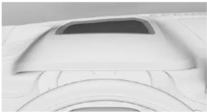
natural_image
Close-up of a white plastic car hood with a circular vent and curved rim (no text or symbols visible)The concept
This system projects important information into the driver's field of vision, e. g., the speed.
The driver can get information without averting his or her eyes from the road.
Information
Follow the instructions for cleaning the Head-up Display, refer to page 294.
Display visibility
The visibility of the displays in the Head-up Display is influenced by the following factors:
▶ Certain sitting positions.
▶ Objects on the cover of the Head-up Display.
▶ Sunglasses with certain polarization filters.
▷ Wet roads.
▶ Unfavorable light conditions.
If the image is distorted, have the basic settings checked by a dealer's service center or another qualified service center or repair shop.
Switching on/off
About iDrive:
- "My Vehicle"
- "System settings"
- "Displays"
- "Head-Up Display"
- "Head-Up Display"
Display
Overview
The following information is displayed on the Head-up Display:
▶ Speed.
▶ Navigation system.
▶ Check Control messages.
▶ Selection list in the instrument cluster.
▶ Driver assistance systems.
Some of this information is only displayed briefly as needed.
Selecting displays in the Head-up Display
About iDrive:
- "My Vehicle"
- "System settings"
- "Displays"
- "Head-Up Display"
- Select desired setting.
The setting is stored for the drive profile currently used.
View
Three different views are available for the Head-up Display:
About iDrive:
- "My Vehicle"
- "System settings"
- "Displays"
-
"Head-Up Display"
-
Select desired setting.
▶ "STANDARD": all displays in the Head-up Display are active.
▶ "REDUCED": the displays in the Head-up Display are reduced to the absolute necessary.
▶ "INDIVIDUAL": all displays in the Head-up Display are active. Individual displays, e.g. Check Control messages, can be individually configured.
The setting is stored for the drive profile currently used.
Setting the brightness
The brightness is automatically adjusted to the ambient brightness.
The basic setting can be adjusted manually.
About iDrive:
- "My Vehicle"
- "System settings"
- "Displays"
- "Head-Up Display"
- "Brightness"
- Turn the controller until the desired brightness is set.
- Press the controller.
When the low beams are activated, the brightness of the Head-up Display can be additionally influenced using the instrument lighting.
The setting is stored for the drive profile currently used.
Adjusting the height
About iDrive:
- "My Vehicle"
- "System settings"
- "Displays"
- "Head-Up Display"
- "Height"
- Turn the controller until the desired height is reached.
- Press the controller.
The setting is stored for the drive profile currently used.
Setting the rotation
The screen of the Head-up Display can be rotated around its own axis.
About iDrive:
- "My Vehicle"
- "System settings"
- "Displays"
- "Head-Up Display"
- "Rotation"
- Turn the controller until the desired setting is selected.
- Press the controller.
The setting is stored for the drive profile currently used.
Special windshield
The windshield is part of the system.
The shape of the windshield makes it possible to display a precise image.
A film in the windshield prevents double images from being displayed.
For this reason, it is strongly suggested to have the special windshield replaced by a dealer's service center or another qualified service center or repair shop.
Lights
Vehicle features and options
This chapter describes all standard, country-specific and optional features offered with the series. It also describes features that are not necessarily available in your car, e.g., due to the selected options or country versions. This also applies to safety-related functions and systems. The respectively applicable country provisions must be observed when using the respective features and systems.
Overview
Switches in the vehicle
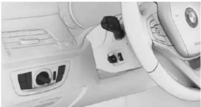
natural_image
Interior view of a car dashboard and steering wheel (no visible text or symbols)The light switch elements is located next to the steering wheel.
Light functions
Symbol Function

Front fog lights

Lights off
Daytime running lights

Parking lights
Symbol Function

Automatic headlight control
Adaptive Light Control

Low beams

Instrument lighting

Right roadside parking lamp

Left roadside parking lamp
Parking lights, cornering lights and roadside parking lights
General information
Position of switch: 0, D
If the driver's door is opened when the drive-ready state is switched off, the exterior lighting is automatically switched off at these switch settings.
Parking lights
Position of switch: EDD
The vehicle is illuminated on all sides.
Do not use the parking lights for extended periods; otherwise, they might drain the battery and disable drive readiness.
When parking, switch on the one-sided roadside parking lamp, refer to page 130.
Low beams
Position of switch: ≡D
The low beams light up when the drive-ready state is switched on.
Roadside parking lights
When the vehicle is parked, a one-sided road-side parking lamp can be switched on.
Press button Function
| P |
Right roadside parking lamp on/off
| ≥p |
Left roadside parking lamp on/off
Welcome lights and headlight courtesy delay feature
Welcome lights
General information
Depending on the equipment, the exterior lighting of the vehicle can be set individually.
Activating/deactivating
About iDrive:
- "My Vehicle"
- "Vehicle settings"
- "Lighting"
- "Exterior lighting"
- Select desired setting:
▶ "Welcome lights"
Parking lights and tail lamps are switched on for a limited time.
▶ "Door handle lighting"
Door handles and the ground in front of the doors are illuminated for a limited time.
"Light carpet"
The area next to the vehicle is illuminated for a limited time.
Headlight courtesy delay feature
General information
The low beams stay lit for a particular time if the high beams are switched on after operational readiness is switched on.
Setting the duration
About iDrive:
- "My Vehicle"
- "Vehicle settings"
- "Lighting"
- "Exterior lighting"
- "Pathway lighting"
- Select desired setting.
Automatic headlight control
The concept
The low beams are switched on and off automatically depending on the ambient brightness, e.g. in tunnels, in twilight or if there is precipitation.
General information
A blue sky with the sun low on the horizon can cause the lights to be switched on.
When emerging from a tunnel during the day, the low beams are not switched off immediately but instead only after approx. 2 minutes.
Activating
Position of switch: ☐
The indicator lamp in the instrument cluster lights up when the low beams are switched on.
System limits
The automatic headlamp control cannot serve as a substitute for your personal judgment of lighting conditions.
E. g. the sensors are unable to detect fog or hazy weather. To avoid safety risks under these conditions, you should always switch on the lights manually.
Daytime running lights
General information
Position of switch: 0, ∃DQE ∥A
The daytime running lights light up when the drive-ready state is switched on. After the drive-ready state is switched off, the parking lights light up in position
Activating/deactivating
In some countries, daytime running lights are mandatory, so it may not be possible to deactivate the daytime running lights.
About iDrive:
-
"My Vehicle"
-
"Vehicle settings"
-
"Lighting"
-
"Exterior lighting"
-
Select desired setting.
The setting is stored for the drive profile currently used.
Adaptive Light Control
The concept
Adaptive Light Control is a variable headlight control system that enables dynamic illumination of the road surface.
General information
Depending on the steering angle and other parameters, the light from the headlight follows the course of the road.
To avoid blinding oncoming traffic, the Adaptive Light Control does not swivel to the driver's side when the vehicle is at a standstill.
Depending on the equipment version, Adaptive Light Control consists of one or several systems:
▶ Cornering light, refer to page 131.
▶ Adaptive headlight range control, refer to page 131.
Activating
Switch setting 📋 with switched-on drive-ready state.
Corner-illuminating lights
In tight curves, e.g., on mountainous roads or when turning, an additional, corner-illuminating lamp is switched on that lights up the inside of the curve when the vehicle is moving below a certain speed.
The turning lights are automatically switched on depending on the steering angle or the use of turn signals.
When driving in reverse, the turning lights may be automatically switched on regardless of the steering angle.
Self-leveling headlights
The self-leveling headlights compensate for acceleration and braking operations in order not to blind the oncoming traffic and to achieve optimum illumination of the roadway.
Malfunction
A Check Control message is displayed.
Adaptive Light Control is malfunctioning or has failed. Have the system checked as soon as possible.
High-beam Assistant
The concept
The high-beam Assistant detects other traffic participants early on and automatically switches the high beams on or off depending on the traffic situation. The assistant ensures that the high beams are activated whenever the traffic situation allows. In the low speed range, the high beams are not switched on by the system.
General information
The system responds to light from oncoming traffic and traffic driving ahead of you, and to adequate illumination, e.g., in towns and cities.
The driver can intervene at any time and switch the high beams on and off as usual.
Depending on the version of the system in the vehicle, the high beams may not switch off for oncoming vehicles, but may only be dimmed in the areas that blind oncoming traffic. In this case, the blue indicator light will stay on.
Activating

natural_image
Close-up of a car seatbelt buckle with a white arrow pointing to the side panel (no text or symbols visible)- Turn the light switch to position ≈
- Press and hold PC button on blinker lever.

The indicator lamp in the instrument cluster lights up.
When the low beams are on, the lights are automatically brightened or dimmed.

The blue indicator lamp in the instrument cluster lights up when the system switches on the high beams.
Deactivating
The High-beam Assistant can be switched off when manually switching the high beams on and off, refer to page 103. To reactivate the High-beam Assistant, press the button on the turn signal lever.
System limits
The High-beam Assistant cannot serve as a substitute for the driver's personal judgment of when to use the high beams. Therefore, manually switch off the high beams in situations where required to avoid a safety risk.
The system is not fully functional in the following situations, and driver intervention may be necessary:
In very unfavorable weather conditions, such as fog or heavy precipitation.
When detecting poorly-lit road users such as pedestrians, cyclists, horseback riders and wagons; when driving close to train or ship traffic; or at animal crossings.
In tight curves, on hilltops or in depressions, in cross traffic or half-obscured on-coming traffic on highways.
In poorly-lit towns and cities or in the presence of highly reflective signs.
When the windshield behind the interior mirror is fogged over, dirty or covered with stickers, etc.
Fog lights
Front fog lights
General information
The low beams must be switched on before switching on the front fog lamps.
Switching on/off
Press button. The green indicator lamp lights up.
If the automatic headlight control, refer to page 130, is activated, the low beams will come on automatically when you switch on the front fog lights.
When the high beams or headlight flasher are activated, the front fog lights are not switched on.
Instrument lighting
The parking lights or low beams must be switched on to adjust the brightness.
Adjust the brightness with the thumbwheel.
Interior lights
General information
Depending on the equipment version, interior lights, footwell lights, entry lamps, door handle lighting, and speaker lighting are automatically controlled.
Overview
Buttons in the vehicle
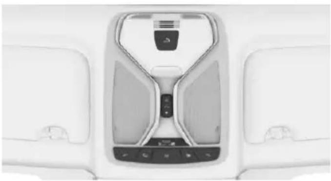
natural_image
Top-down view of a white car interior with visible seats and dashboard (no text or symbols)
Interior lights
Reading lights
Switching the interior lights on and off

Press button.
To switch off permanently: press the button and hold for approx. 3 seconds.
The interior lights in the rear of the vehicle can be switched on and off independently. The button is located in the rear roofliner.
Switching the reading lamps on and off manually
Press button.
The reading lamps are located at the front and rear next to the interior lights.
Ambient light
General information
Depending on the equipment version, lighting can be adjusted for some lights in the car's interior.
Switching on/off
The ambient light is switched on when the vehicle is unlocked, and switched off when the vehicle is locked.
If the ambient light was deactivated via iDrive, it will not be switched on when the vehicle is unlocked.
Selecting color scheme
About iDrive:
- "My Vehicle"
- "Vehicle settings"
- "Lighting"
- "Interior lighting"
- "Color"
- Select desired setting.
Setting the brightness
About iDrive:
- "My Vehicle"
- "Vehicle settings"
- "Lighting"
- "Interior lighting"
- "Brightness"
- Select desired setting.
Dimmed when driving
About iDrive:
- "My Vehicle"
- "Vehicle settings"
- "Lighting"
- "Interior lighting"
- "Dimmed while driving"
The interior lighting is dimmed for some lights while driving.
Panoramic glass sunroof, lighting
If the panoramic glass sunroof is opened or the sliding visor closed, lighting of the panoramic glass sunroof is switched off.
When closing the sliding visors, only the lighting for the area in question is switched off.
BMW Touch Command
The ambient light can also be operated using BMW Touch Command.
Bowers & Wilkins High End Surround Sound System
General information
Some speakers in the vehicle are illuminated. Brightness can be individually set.
Switching on/off
The speaker lighting is switched on when the vehicle is unlocked, and switched off when the vehicle is locked.
If the speakers are muted, speaker lighting will be switched off.
Setting the brightness
About iDrive:
- "My Vehicle"
- "Vehicle settings"
- "Lighting"
- "Bowers & Wilkins"
- "Brightness"
- Select desired setting.
BMW Touch Command
The operation of the Bowers & Wilkins high-end surround sound system is also possible with BMW Touch Command.
Ambient light accent
General information
The ambient light accent illuminates the door pillar in the rear.
Switching on/off
The ambient light accent is switched on when the vehicle is unlocked, and switched off when the vehicle is locked.
When opening a rear door, the ambient light accent of the respective door pillar is switched off.
Setting the brightness
About iDrive:
- "My Vehicle"
- "Vehicle settings"
- "Lighting"
- "Accent lighting in rear"
- "Brightness"
The last brightness set is displayed. - Select desired setting.
Touch sensor
The ambient light accent is fitted with a touch sensor. The ambient highlight is switched on or off with a brief touch of the chrome bar. The brightness is changed with a long touch.
BMW Touch Command
The ambient highlight can also be operated using BMW Touch Command.
Safety
Vehicle features and options
This chapter describes all standard, country-specific and optional features offered with the series. It also describes features that are not necessarily available in your car, e. g., due to
the selected options or country versions. This also applies to safety-related functions and systems. The respectively applicable country provisions must be observed when using the respective features and systems.
Airbags
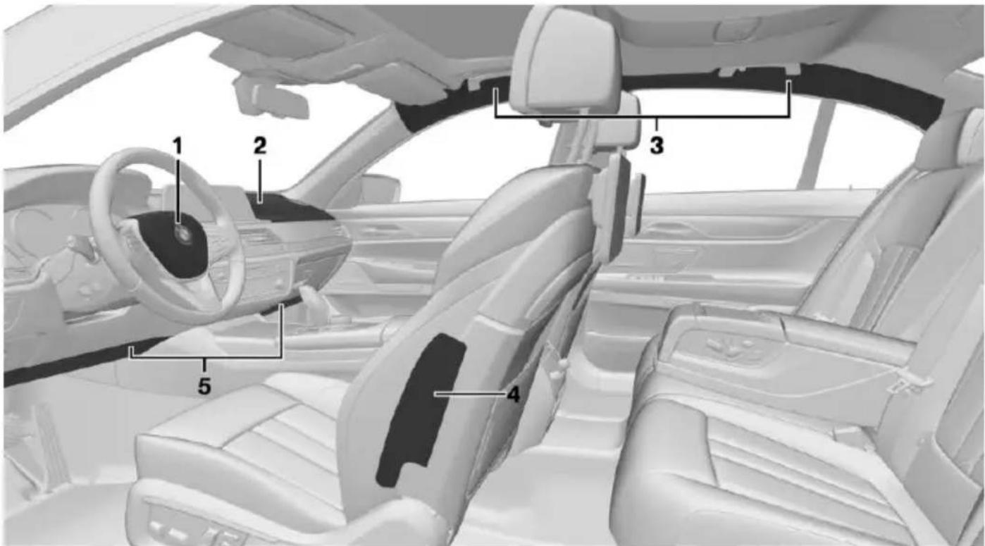
text_image
Diagram of a car interior with numbered parts for identification and assembly reference.1 Front airbag, driver
2 Front airbag, front passenger
3 Head airbag
4 Side airbag
5 Knee airbag
Front airbags
Front airbags help protect the driver and front passenger by responding to frontal impacts in which safety belts alone would not provide adequate restraint.
Side airbag
In a lateral impact, the side airbag supports the side of the body in the chest and lap area.
Head airbag
In a lateral impact, the head airbag supports the head.
Ejection Mitigation
The head airbag system is designed as an ejection mitigation countermeasure to reduce the likelihood of ejections of vehicle occupants through side windows during rollovers or side impact events.
Knee airbag
The knee airbag supports the legs in a frontal impact.
Protective action
Airbags are not triggered in every impact situation, e.g., in less severe accidents or rear-end collisions.
Information for optimum effect of the airbags

WARNING
If the seat position is incorrect or the deployment area of the airbags is impacted, the airbag system cannot protect as intended or cause additional injuries due to triggering. There is risk of injuries or danger to life. Observe the Information for optimum protective effect of the airbag system.
Keep at a distance from the airbags.
▶ Always grasp the steering wheel on the steering wheel rim. Hold your hands at the 3 o'clock and 9 o'clock positions, to keep the risk of injury to your hands or arms as low as possible when the airbag is triggered.
▶ Make sure that the front passenger is sitting correctly, i.e., keeps his or her feet and legs in the floor area.
▶ Make sure that occupants keep their heads away from the side airbag.
There should be no persons, animals or objects between an airbag and a person.
Do not use the cover of the front airbag on the front passenger side as a storage area.
▶ Dashboard and windshield on the front passenger side must stay clear - do not attach adhesive labels or coverings and do not attach brackets or cables, e. g., for GPS devices or' mobile phones.
Do not apply adhesive materials to the air-bag cover panels, do not cover them or modify them in any way.
Do not place slip covers, seat cushions or other objects on the front passenger seat that are not specifically suited for seats with integrated side airbags.
Do not hang pieces of clothing, such as jackets, over the backrests.
▶ Never modify either the individual components or the wiring in the airbag system. This also applies to steering wheel covers, the dashboard, and the seats.
Do not remove the airbag system.
Even when you follow all instructions very closely, injury from contact with the airbags cannot be ruled out in certain situations.
The ignition and inflation noise may lead to short-term and, in most cases, temporary hearing impairment in sensitive individuals.
Warnings and information on the airbags are also found on the sun visors.
Functional readiness of the airbag system
Information

WARNING
Individual components can be hot after triggering of the airbag system. There is risk of injuries. Do not touch individual components.

WARNING
Improperly executed work can lead to failure, malfunction or unintentional triggering of the airbag system. In the case of a malfunction, the airbag system could not trigger as intended in the event of an accident despite re-
spective accident severity. There is risk of injuries or danger to life. Have the airbag system checked, repaired, dismantled and scrapped by a dealer's service center or another qualified service center or repair shop.
Correct function

When drive readiness is switched on, the warning lamp in the instrument cluster lights up briefly and thereby indicates the function readiness of the entire air-bag system and the belt tensioners.
Airbag system malfunctioning
▶ Warning lamp does not come on when drive readiness is switched on.
The warning lamp lights up continuously.
Automatic deactivation of the front-seat passenger airbags
The concept
The system reads if the front passenger seat is occupied by measuring the human body's resistance.
Front, knee and side airbag on the front passenger's side are either activated or deactivated.
Information
Before transporting a child on the front passenger seat, refer to the safety notes and instructions for children on the front passenger seat, see Children.

WARNING
The ensure the front-seat passenger air-bag function, it must be detected, whether a person occupies the front passenger seat. The entire seat cushion area must be used for this purpose. There is risk of injuries or danger to life. Make sure that the front passenger keeps his or her feet in the floor area.
Malfunction of the automatic deactivation system
When transporting older children and adults, the front-seat passenger airbags may be deactivated in certain sitting positions. In this case, the indicator lamp for the front-seat passenger airbags lights up.
In this case, change the sitting position so that the front-seat passenger airbags are activated and the indicator lamp goes out.
If it is not possible to activate the airbags, have the person sit in the rear.
To enable correct recognition of the occupied seat cushion
Do not attach covers, cushions, ball mats or other items to the front passenger seat unless they are specifically determined to be safe for use on the front passenger seat.
Do not place any electronic devices on the passenger seat if a child restraint system is to be installed on it.
Do not place objects under the seat that could press against the seat from below.
▶ No moisture in or on the seat.
Indicator lamp for the front-seat passenger airbags
The indicator lamp for the front-seat passenger airbag in the roofliner indicates the operating state of the front-seat passenger airbag.
The lamp indicates whether the airbags are either activated or deactivated.
After drive readiness is switched on, the lamp briefly lights up and then indicates whether the airbags are either activated or deactivated.
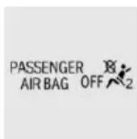
The indicator lamp lights up when a child is properly seated in a child restraint fixing system or when the seat is empty. The airbags on the front passenger side are not activated.
The indicator lamp does not light up when, e.g., a correctly seated person of sufficient size is detected on the seat. The airbags on the front passenger side are activated.
Detected child seats
The system generally detects children seated in a child seat, particularly in child seats required by NHTSA when the vehicle was manufactured. After installing a child seat, make sure that the indicator lamp for the front-seat passenger airbags lights up. This indicates that the child seat has been detected and the front-seat passenger airbags are not activated.
Strength of the driver's and front-seat passenger airbag
The explosive power that activates driver's/front passenger's airbags very much depends on the positions of the driver's/front passenger's seat.
With a respective message appearing on Control Display calibrate the front seats to keep the accuracy of this function over the long-term.
Calibrating the front seats

WARNING
There is risk of jamming when moving the seats. There is risk of injuries or risk of property damage. Make sure that the area of movement of the seat is clear prior to any adjustment.
A corresponding message appears on the Control Display.
- Press the switch and move the respective seat all the way forward.
- Press the switch forward again. The seat still moves forward slightly.
- Readjust the seat to the desired position.
The calibration procedure is completed when the message on the Control Display disappears.
If the message continues to be displayed, repeat the calibration.
If the message does not disappear after a repeat calibration, have the system checked as soon as possible.
Intelligent Safety
The concept
Intelligent Safety enables central operation of the driver assistance system. Depending on how the vehicle is equipped, Intelligent Safety consists of one or more systems that can help prevent a imminent collision.
▶ Front-end collision warning with braking function, refer to page 140.
▶ Pedestrian warning with City Braking function, refer to page 144.
▶ Night Vision with pedestrian and animal detection, refer to page 147.
▶ Lane departure warning, refer to page 150.
▶ Active Blind Spot Detection, refer to page 153.
▶ Side collision warning, refer to page 156.
Information

WARNING
Indicators and warnings do not relieve from the personal responsibility. Due to system limits, warnings or reactions of the system may not be output or they may be output too late or incorrectly. There is risk of an accident. Adjust the driving style to the traffic conditions. Watch traffic closely and actively interfere in the respective situations.

WARNING
Due to system limits, individual functions can malfunction during tow-starting/towing with the Intelligent Safety systems activated, e.g. approach control warning with light braking function. There is risk of an accident. Switch all Intelligent Safety systems off prior to tow-starting/towing.
Overview
Button in the vehicle
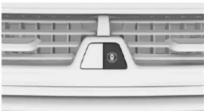
natural_image
Front view of a car grille with a black and white panel showing the number 8 (no text or symbols beyond the label)
Intelligent Safety
Switching on/off
Some Intelligent Safety systems are automatically active after every departure. Some Intelligent Safety systems activate according to the last setting.
| Press button | Status |
 | Button lights up green: all Intelligent Safety systems are switched on. |
 | Button lights up orange: some Intelligent Safety systems are switched off or settings for the sub-functions were changed. |
 | Button does not light up: all Intelligent Safety systems are switched off. |
Press button:
The menu for the intelligent safety system is displayed.
If all Intelligent Safety systems were switched off, all systems are now switched on.
"Configure INDIVIDUAL": depending on the equipment version, the Intelligent Safety systems can be individually configured. The individual settings are activated and stored for the profile currently used. As soon as a setting is changed on the menu, all settings of the menu are activated, the button lights up orange.
Press button repeatedly. It is switched between the following settings:
"ALL ON" All Intelligent Safety systems are switched on. For the sub-functions, e.g. setting for warning time, basic settings are activated.
"INDIVIDUAL": the Intelligent Safety systems are switched on according to the individual settings.
Some Intelligent Safety systems cannot be individually switched off.
Press and hold this button:
All Intelligent Safety systems are
turned off.
Collision warning with braking function
The concept
The system can help prevent accidents. If an accident cannot be prevented, the system will help reduce the collision speed.
The system sounds a warning before an imminent collision and actuates brakes independently if needed.
The system is controlled using a camera.
If the vehicle is equipped with Active Cruise Control with Stop & Go function, ACC, the
front-end collision warning is additionally controlled via the cruise control radar sensor.
Active Protection: if a collision seems to be unavoidable, PreCrash functions are triggered.
The front-end collision warning is available even if cruise control has been deactivated.
With the vehicle approaching another vehicle intentionally, the collision warning and braking are delayed in order to avoid false system reactions.
General information
The system issues a two-phase warning of a possible danger of collision with vehicles at speeds above approx. 3 mph/5 km/h. Time of warnings may vary with the current driving situation.
Detection range
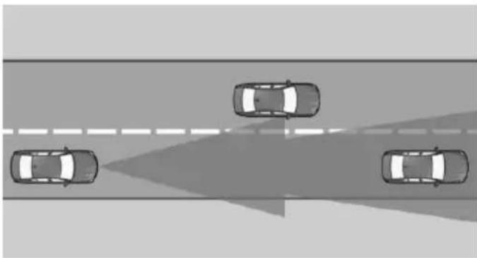
natural_image
Top-down view of four cars driving on a road with a shadowed lane (no text or symbols visible)It responds to objects if they are detected by the system.
Information

WARNING
Indicators and warnings do not relieve from the personal responsibility. Due to system limits, warnings or reactions of the system may not be output or they may be output too late or incorrectly. There is risk of an accident. Adjust the driving style to the traffic conditions. Watch traffic closely and actively interfere in the respective situations.

WARNING
Due to system limits, individual functions can malfunction during tow-starting/towing with the Intelligent Safety systems activated, e.g. approach control warning with light braking function. There is risk of an accident. Switch all Intelligent Safety systems off prior to tow-starting/towing.
Overview
Button in the vehicle
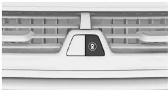
natural_image
Front view of a car air conditioner grille with a black and white panel showing the number 8 (no text or symbols beyond the label)
Intelligent Safety
Camera
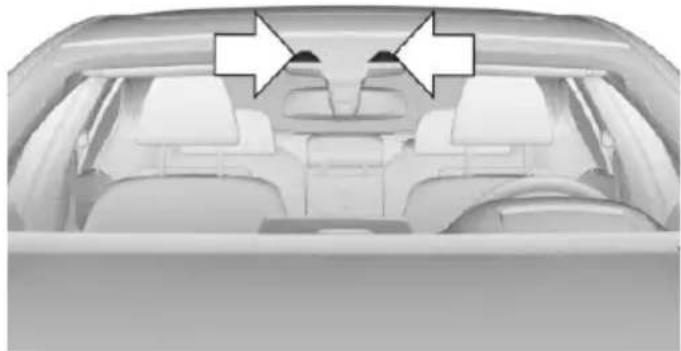
natural_image
Interior view of a car showing rear seats and dashboard (no visible text or symbols)The camera is installed near the interior rear-view mirror.
Keep the windshield in the area behind the interior rearview mirror clean and clear.
With Active Cruise Control: radar sensor
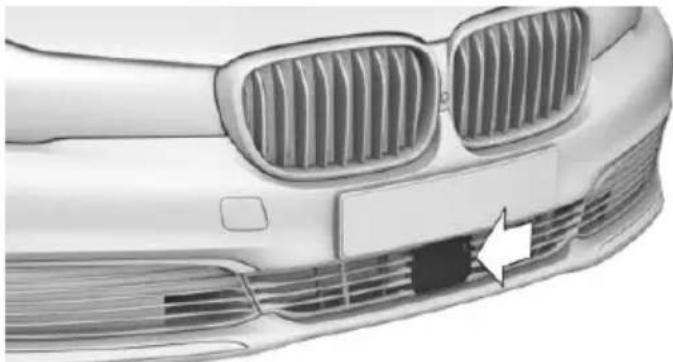
natural_image
Front view of a car's head and grille with visible grating and ventilation grilles (no text or symbols)The radar sensor is located in the lower area of the front bumper.
Always keep radar sensor clean and unobstructed.
Switching on/off
Switching on automatically
The system is automatically active after every driving-off.
Switching on/off manually

Press button:
The menu for the intelligent safety system is displayed.
If all Intelligent Safety systems were switched off, all systems are now switched on.
"Configure INDIVIDUAL": depending on the equipment version, the Intelligent Safety systems can be individually configured. The individual settings are activated and stored for the profile currently used. As soon as a setting is changed on the menu, all settings of the menu are activated, the button lights up orange.
Press button repeatedly. It is switched between the following settings:
"ALL ON" All Intelligent Safety systems are switched on. Basic settings are activated for the subfunctions.
"INDIVIDUAL": the Intelligent Safety systems are switched on according to the individual settings.
Some Intelligent Safety systems cannot be individually switched off.
Press and hold this button:
All Intelligent Safety systems are
turned off.
Press button
Status
Button lights up green: all Intelligent Safety systems are switched on.
Button lights up orange: some Intelligent Safety systems are switched off or settings for the sub-functions were changed.
Button does not light up: all Intelligent Safety systems are switched off.
Setting the warning time
About iDrive:
- "My Vehicle"
- "Vehicle settings"
- "Intelligent Safety"
- "Frontal Collision Warning"
- Select desired setting.
The selected time is stored for the profile currently used.
Warning with braking function
Display
If a collision with a recognized vehicle is imminent a warning symbol appears in the instrument cluster and in the Head-Up Display.
Symbol Measure

Symbol lights up red: prewarning.
Brake and increase distance.

Symbol flashes red and an acoustic signal sounds: acute warning.
You are requested to intervene by braking or make an evasive maneuver.
Prewarning
This warning is issued, e.g., when there is the impending danger of a collision or the distance to the vehicle ahead is too small.
The driver must intervene actively when there is a prewarning.
Acute warning with braking function
Acute warning in displayed in case of the imminent danger of a collision when the vehicle approaches another object at a relatively high differential speed.
The driver must intervene actively when there is an acute warning. If necessary, the driver is assisted by an automatic braking intervention in a possible risk of collision.
Acute warnings can also be triggered without previous forewarning.
Brake intervention, City braking function
The warning prompts the driver himself/herself to react. During a warning, the maximum braking force is used when the brake is actuated. Premise is sufficiently quick and hard stepping on the brake pedal.
The system can additionally assist possibly with automatic braking intervention if there is risk of a collision.
At low speeds the vehicle can be decelerated to a complete stop.
The braking intervention takes place up to approx. 50 mph/80 km/h.
The braking intervention is executed only if DSC Dynamic Stability Control is switched on.
The braking intervention can be interrupted by stepping on the accelerator pedal or by actively moving the steering wheel.
Object detection can be restricted. Limitations of the detection range and functional restrictions are to be considered.
With radar sensor and Active Cruise Control: braking intervention
The warning prompts the driver himself/herself to react. During a warning, the maximum braking force is used when the brake is actuated.
Premise is sufficiently quick and hard stepping on the brake pedal.
The system can assist with automatic braking intervention if there is risk of a collision.
The intervention can bring the vehicle to a complete stop.
The braking intervention is executed only if DSC Dynamic Stability Control is switched on.
Above approx. 130 mph/210 km/h the braking intervention occurs as a brief braking pressure. No automatic delay occurs.
The braking intervention can be interrupted by stepping on the accelerator pedal or by actively moving the steering wheel.
Object detection can be restricted. Limitations of the detection range and functional restrictions are to be considered.
System limits
Detection range
The system's detection potential is limited.
Thus a system reaction might not come or might come late.
E. g. the following situations may not be detected:
▶ Slow moving vehicles when you approach them at high speed.
▶ Vehicles that suddenly swerve in front of you, or sharply decelerating vehicles.
▶ Vehicles with an unusual rear appearance.
▶ Two-wheeled vehicles ahead of you.
Functional limitations
The system may not be fully functional in the following situations:
In heavy fog, rain, sprayed water or snowfall.
In tight curves.
▶ If the driving stability control systems are limited or deactivated, e.g., DSC OFF.
If the area of the front windshield in front of the interior mirror is dirty or covered.
▶ Depending on equipment, if the radar sensor is dirty or obscured.
▶ Up to 10 seconds after the start of the engine, via the Start/Stop button.
During calibration of the camera immediately after vehicle delivery.
▶ If there are constant blinding effects because of oncoming light, e. g., from the sun low in the sky.
Warning sensitivity
The more sensitive the warning settings are, e.g. the warning time, the more warnings are displayed. However, there may also be an excess of premature warnings.
Pedestrian warning with City braking function
The concept
The system can help prevent accidents with pedestrians.
The system issues a warning in the city driving speed area if there is imminent danger of a collision with pedestrians and includes a braking function.
The camera in the area of the rearview mirror controls the system.
Active Protection: if a collision seems to be unavoidable, PreCrash functions are triggered.
General information
The system warns of possible collisions with pedestrians at speeds from approx. 6 mph/10 km/h to approx. 35 mph/60 km/h and supports you with a braking intervention shortly before a collision. Under those circumstances it reacts to people who are within the detection range of the system.
Detection range
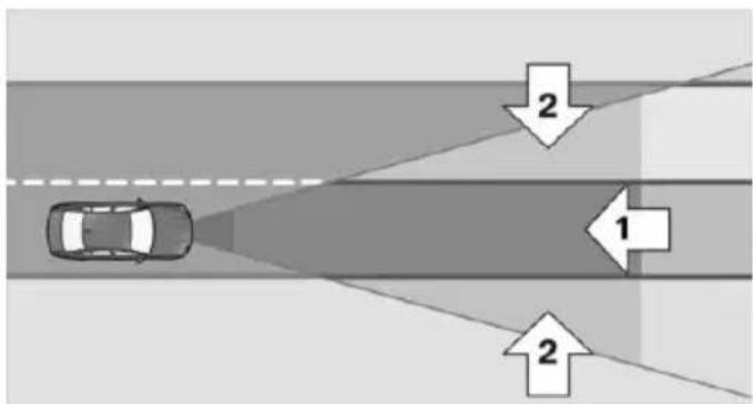
text_image
Diagram showing a car driving on a road with two directional arrows labeled 1 and 2 indicating flow or movement directions.The detection area in front of the vehicle is divided into two areas
▶ Central area, arrow 1, directly in front of the vehicle.
▶ Expanded area, arrow 2, to the right and left.
A collision is imminent if pedestrians are located within the central area. A warning is issued about pedestrians who are located within the extended area only if they are moving in the direction of the central area.
Information

WARNING
Indicators and warnings do not relieve from the personal responsibility. Due to system limits, warnings or reactions of the system may not be output or they may be output too late or incorrectly. There is risk of an accident. Adjust the driving style to the traffic conditions. Watch traffic closely and actively interfere in the respective situations.

WARNING
Due to system limits, individual functions can malfunction during tow-starting/towing with the Intelligent Safety systems activated, e.g. approach control warning with light braking function. There is risk of an accident. Switch all Intelligent Safety systems off prior to tow-starting/towing.
Overview
Button in the vehicle
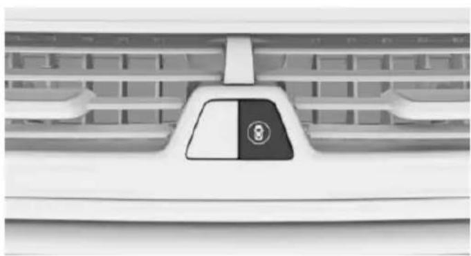
natural_image
Front view of a car air conditioner grille with a black triangular button labeled '8' (no text or symbols beyond the number)
Intelligent Safety
Camera
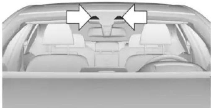
natural_image
Interior view of a car showing rear seats and dashboard (no visible text or symbols)The camera is installed near the interior rear-view mirror.
Keep the windshield in the area behind the interior rearview mirror clean and clear.
Switching on/off
Switching on automatically
The system is automatically active after every driving-off.
Switching on/off manually
Press button:
The menu for the intelligent safety system is displayed.
If all Intelligent Safety systems were switched off, all systems are now switched on.
"Configure INDIVIDUAL": depending on the equipment version, the Intelligent Safety systems can be individually configured. The individual settings are activated and stored for the profile currently used. As soon as a setting is changed on the menu, all settings of the menu are activated, the button lights up orange.
Press button repeatedly. It is switched between the following settings:
"ALL ON" All Intelligent Safety systems are switched on. Basic settings are activated for the subfunctions.
"INDIVIDUAL": the Intelligent Safety systems are switched on according to the individual settings.
Some Intelligent Safety systems cannot be individually switched off.
Press and hold this button:
All Intelligent Safety systems are
turned off.
Press button
Status
Button lights up green: all Intelligent Safety systems are switched on.
Button lights up orange: some Intelligent Safety systems are switched off or settings for the sub-functions were changed.
Button does not light up: all Intelligent Safety systems are switched off.
Warning with braking function
Display
If a collision with a person detected in this way is imminent, a warning symbol appears on the instrument cluster and in the Head-up Display.

The red symbol is displayed and a signal sounds.
Intervene immediately by braking or make an evasive maneuver.
Braking intervention
The warning prompts the driver himself/herself to react. During a warning, the maximum braking force is used when the brake is actuated. Premise for the brake booster is sufficiently quick and hard stepping on the brake pedal.
The system can additionally assist with braking intervention if there is risk of a collision.
At low speeds the vehicle can be decelerated to a complete stop.
The braking intervention is executed only if DSC Dynamic Stability Control is switched on.
The braking intervention can be interrupted by stepping on the accelerator pedal or by actively moving the steering wheel.
Object detection can be restricted. Limitations of the detection range and functional restrictions are to be considered.
System limits
Detection range
The detection potential of the camera is limited.
Thus a warning might not be issued or be issued late.
E. g. the following situations may not be detected:
▶ Partially covered pedestrians.
▶ Pedestrians that are not detected as such because of the viewing angle or contour.
▶ Pedestrians outside of the detection range.
▶ Pedestrians having a body size less than 32 in/80 cm.
Functional limitations
The system may not be fully functional or may not be available in the following situations:
In heavy fog, rain, sprayed water or snowfall.
In tight curves.
▶ If the driving stability control systems are deactivated, e.g. DSC OFF.
▶ If the field of view of the camera or the front windshield are dirty or covered.
▶ Up to 10 seconds after the start of the engine, via the Start/Stop button.
During calibration of the camera immediately after vehicle delivery.
▶ If there are constant blinding effects because of oncoming light, e. g., from the sun low in the sky.
▶ When it is dark outside.
Night Vision with pedestrian and animal detection
The concept
Night Vision with pedestrian and animal detection is a night vision system.
An infrared camera scans the area in front of the vehicle and issues a warning if it detects pedestrians and animals on the street. Warm objects that are similar in shape to human beings or animals are detected by the system. If necessary, the heat image can be displayed on the Control Display.
Heat image
natural_image
Silhouette of a herd of animals walking along a path under a dark sky with trees (no text or symbols)The image shows the heat radiated by objects in the field of view of the camera.
Warm objects have a light appearance and cold objects a dark appearance.
The ability to detect an object depends on the temperature difference between the object and the background and on the level of heat radiation emitted by the object. Objects that are similar in temperature to the environment or that radiate very little heat are difficult to detect.
For safety reasons, when driving at speeds above approx. 3 mph/5 km/h and in low ambient light, the image is only displayed when the low beams are activated.
A still image is displayed at regular intervals for a fraction of a second.
Pedestrian and animal detection
natural_image
Silhouette of a person walking on a road with a car and trees in the background (no text or symbols)Object detection and warning only functions in darkness.
Objects whose form is similar to people with sufficient heat radiation are detected.
In addition, the system also detects animals above a certain minimum size, e.g., deer.
Display on the Control Display with heat image activated:
▶ People detected by the system: in light yellow.
▶ Animals detected by the system: in dark yellow.
Range of object detection, with good ambient conditions:
▶ Pedestrian detection: up to approx. 330 ft/100 m
▶ Detection of large animals: up to approx. 490 ft/150 m
▶ Detection of medium animals: up to approx. 230 ft/70 m
Environmental influences can limit the availability of object detection.
If the vehicle systems detect that the vehicle is located in a residential area, the animal detection is temporarily switched off.
Information

WARNING
The system does not relieve from the personal responsibility to correctly assess visibility and traffic situation. There is risk of an accident. Adjust the driving style to the traffic conditions. Watch traffic closely and actively interfere in the respective situations.
Overview
Buttons in the vehicle
natural_image
Front view of a car air conditioner grille with a black and white panel showing the brand logo (no text or symbols visible)
Intelligent Safety
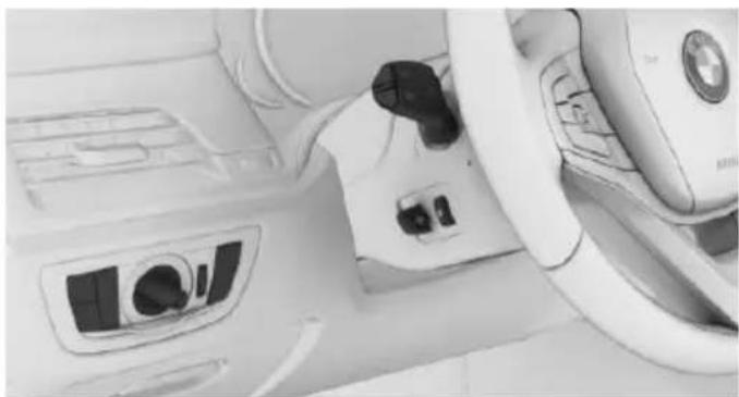
natural_image
Interior view of a car dashboard and steering wheel (no visible text or symbols)
Switch on/switch off heat image
Camera
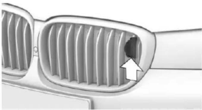
natural_image
Close-up of a car's front grille with a white arrow pointing to a specific grille (no text or symbols)The camera is automatically heated when the external temperatures are low.
The camera lens is automatically cleaned together with the headlights.
Switching on/off
Switching on automatically
When it is dark outside, the system is automatically active after every driving-off.
Switching on heat image additionally
The heat image from the Night Vision camera can also be displayed on the Control Display. This function has no effect on object detection.
Press button.
The image from the camera is displayed on the Control Display.
Set heat image via iDrive
With heat image switched on:
- Select brightness or contrast.
▶ "Brightness".
▶ "Contrast".
- Set the desired value.
Display
Warning of people or animals in danger
If a collision with a person or an animal detected in this way is imminent, a warning symbol appears on the instrument cluster and in the Head-up Display.
Although both the shape and the heat radiation are analyzed, false warnings cannot be ruled out.
Warning area in front of the vehicle
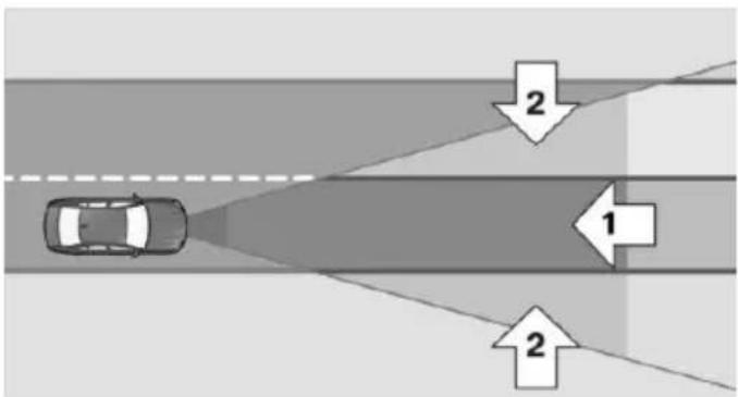
flowchart
graph TD
    A["Car"] --> B{Light Path}
    B --> C["Path 1"]
    B --> D["Path 2"]
The warning area for the pedestrian warning consists of two parts:
▶ Central area, arrow 1, directly in front of the vehicle.
▶ Expanded area, arrow 2, to the right and left.
With animal warnings, no distinction is made between the central or expanded area.
The entire area moves along with the vehicle in the direction of the steering angle and changes with the vehicle speed. As the vehicle speed increases, the area becomes longer and wider, e.g.
Symbols
Symbol Meaning

Pedestrian warning

Animal warning
Symbol lights up red.
Advance warning: intervene actively by braking or making an evasive maneuver
Symbol flashes red and a signal sounds.
Acute warning: intervene immediately by braking or making an evasive maneuver.
The displayed symbol shows the side of the road on which the person or animal was detected.
Prewarning
Prewarning for persons is displayed when a person is detected in the central area immediately in front of the vehicle as well as on the left or right side in the extended area.
Prewarning for animals is displayed when an animal is detected in the front of the vehicle.
The driver must intervene actively when there is a prewarning.
Acute warning
Acute warning is displayed if a person or an animal is detected in direct proximity if front of the vehicle.
The driver must immediately intervene actively when there is an acute warning.
Active Protection: if a collision seems to be unavoidable, PreCrash functions are triggered.
Display in the Head-up Display
The warning is displayed simultaneously in the Head-up Display and on the instrument cluster.
System limits
Basic limits
System operation is limited in situations such as the following:
On steep hills, in steep depressions or in tight curves.
▶ When the camera is dirty or the protective glass is damaged.
▶ In heavy fog, rain or snowfall.
▶ At very high external temperatures.
Limits of pedestrian and animal detection
In some situations, it may occur that pedestrians are detected as animals or animals as pedestrians.
Small animals are not detected by the object detection function, even if they are clearly visible in the image.
Limited detection, e.g. in the following circumstances:
▶ People or animals who are fully or partially covered, especially when their heads are covered.
▶ People who are not in an upright position, e.g., lying down.
▶ Cyclists on unconventional bicycles (e.g., recumbent bicycles).
▶ After physical damage to the system, e.g., after an accident.
No display on the rear screen
The image from Night Vision cannot be displayed on the rear screen.
Lane departure warning
The concept
This system alerts at speeds between 45 mph/70 km/h and 130 mph/210 km/h when the vehicle on roads with lane markings is about to leave the lane.
The steering wheel begins vibrating gently in the event of warnings. The time of the warning may vary depending on the current driving situation.
The system does not provide a warning if the turn signal is set before leaving the lane.
Vehicles with side collision warning: if the vibrating steering wheel is ignored and the lane marking crossed, the system intervenes with a brief active steering intervention and helps to maintain the vehicle in the lane.
Information

WARNING
The system does not relieve from the personal responsibility to correctly assess route and traffic situation. There is risk of an accident. Adjust the driving style to the traffic conditions. Watch traffic closely and actively interfere in the respective situations. In the event of a warning, do not unnecessarily jerk the steering wheel.
Overview
Button in the vehicle
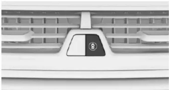
natural_image
Front view of a car grille with a black and white stylized logo (no readable text or symbols)
Intelligent Safety
Camera
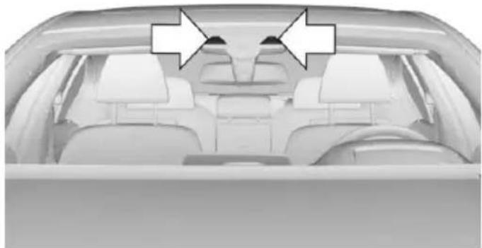
natural_image
Interior view of a car showing two white arrows pointing to the rear seats (no text or symbols visible)The camera is installed near the interior rear-view mirror.
Keep the windshield in the area behind the interior rearview mirror clean and clear.
Switching on/off
Switching on automatically
The lane departure warning is automatically activated after departure, if the function was switched on the last time the engine was stopped.
Switching on/off manually
Press button:
The menu for the intelligent safety system is displayed.
If all Intelligent Safety systems were switched off, all systems are now switched on.
"Configure INDIVIDUAL": depending on the equipment version, the Intelligent Safety systems can be individually configured. The individual settings are activated and stored for the profile currently used. As soon as a setting is changed on the menu, all settings of the menu are activated, the button lights up orange.
Press button repeatedly. It is switched between the following settings:
"ALL ON" All Intelligent Safety systems are switched on. Basic settings are activated for the subfunctions.
"INDIVIDUAL": the Intelligent Safety systems are switched on according to the individual settings.
Some Intelligent Safety systems cannot be individually switched off.
Press and hold this button:
All Intelligent Safety systems are
turned off.
| Press button | Status |
| Button lights up green: all Intelligent Safety systems are switched on. | |
| Button lights up orange: some Intelligent Safety systems are switched off or settings for the sub-functions were changed. | |
 | Button does not light up: all Intelligent Safety systems are switched off. |
Setting warning sensitivities
About iDrive:
- "My Vehicle"
- "Vehicle settings"
- "Intelligent Safety"
- "Lane Departure Warning"
- Select desired setting.
▶ "Always": the system always alerts within the technical limitations.
▶ "Reduced": some warning are suppressed depending on the situation, e.g. during passing without turn signal or when purposefully driving over lane markings in curves.
▶ "Off": no warnings are issued.
The selected setting is stored for the drive profile currently used.
Set force of the steering wheel vibration
About iDrive:
- "My Vehicle"
- "Vehicle settings"
- "Steering wheel vibration"
- Select desired setting.
The setting is applied to all Intelligent Safety systems and stored for the profile currently used.
Vehicles with side collision warning: switching steering intervention on/off
The steering intervention can be switched on and off separately for Active Blind Spot Detection and lane departure warning.
About iDrive:
- "My Vehicle"
- "Vehicle settings"
- "Intelligent Safety"
- "Steering intervention"
The selected setting is stored for the drive profile currently used.
Display in the instrument cluster

Green symbol: at least one lane marking was detected and warnings can be issued.
Issued warning
If you leave the lane and if a lane marking has been detected, the steering wheel begins vibrating.
If the turn signal is set before changing the lane, a warning is not issued.
Vehicles with side collision warning: if the vibrating steering wheel is ignored and the lane marking crossed, the system intervenes with a brief active steering intervention and helps to maintain the vehicle in the lane. The steering intervention can be noticed on the steering wheel and can be manually overridden at any time.
End of warning
The warning is canceled in the following situations:
▶ Automatically after approx. 3 seconds.
▶ When returning to your own lane.
▶ When braking hard.
▶ When using the turn signal.
▶ When DSC is actively controlling stability.
System limits
Functional limitations
The system may not be fully functional in the following situations:
▶ In heavy fog, rain or snowfall.
In the event of missing, worn, poorly visible, merging, diverging, or multiple lane markings such as in construction areas.
▶ When lane markings are covered in snow, ice, dirt or water.
In tight curves or on narrow lanes.
▷ When the lane markings are covered by objects.
▷ When driving very close to the vehicle in front of you.
▶ If there are constant blinding effects because of oncoming light, e. g., from the sun low in the sky.
When the windshield in front of the interior rearview mirror is fogged over, dirty or covered with stickers, etc.
During calibration of the camera immediately after vehicle delivery.
A Check Control message is displayed when the system is not fully functional.
Warning sensitivity
The more sensitive the warning settings are, the more warnings are displayed. However, there may also be an excess of undesired warnings.
Active Blind Spot Detection
The concept
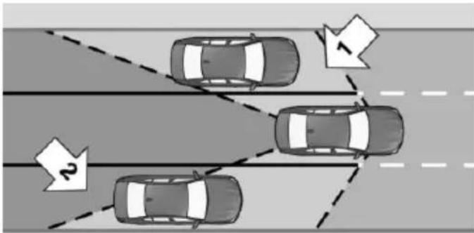
Two radar sensors in the rear bumper monitor the area behind and next to the vehicle starting from a preset minimum speed.
The minimum speed is country-specific and is displayed in the menu for the Intelligent Safety systems.
The system indicates whether there are vehicles in the blind spot, arrow 1, or approaching from behind on the adjacent lane, arrow 2.
The lamp in the exterior mirror is dimmed.
Before you change lanes after setting the turn signal, the system issues a warning in the situations described above.
The lamp in the exterior mirror flashes and the steering wheel vibrates.
Vehicles with side collision warning: at speeds between 45 mph/70 km/h and
130 mph/210 km/h, the system can intervene with a brief active steering intervention and help to return the vehicle into the lane.
Information

WARNING
The system does not relieve from the personal responsibility to correctly assess visibility and traffic situation. There is risk of an accident. Adjust the driving style to the traffic conditions. Watch traffic closely and actively interfere in the respective situations.
Overview
Button in the vehicle
natural_image
Front view of a car air conditioner grille with no visible text or symbols
Intelligent Safety
Radar sensors
natural_image
Front view of a white car showing side bumper and side paint mark, with arrows pointing to specific areas (no text or symbols present)The radar sensors are located in the rear bumper.
Always keep the bumper in the area of the radar sensors clean and unobstructed.
Switching on/off
Switching on automatically
The Active Blind Spot Detection is automatically activated after departure, if the function was switched on the last time the engine was stopped.
Switching on/off manually
Press button:
The menu for the intelligent safety system is displayed.
If all Intelligent Safety systems were switched off, all systems are now switched on.
"Configure INDIVIDUAL": depending on the equipment version, the Intelligent Safety systems can be individually configured. The individual settings are activated and stored for the profile currently used. As soon as a setting is changed on the menu, all settings of the menu are activated, the button lights up orange.
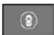
Press button repeatedly. It is switched between the following settings:
"ALL ON" All Intelligent Safety systems are switched on. Basic settings are activated for the subfunctions.
"INDIVIDUAL": the Intelligent Safety systems are switched on according to the individual settings.
Some Intelligent Safety systems cannot be individually switched off.
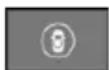
Press and hold this button:
All Intelligent Safety systems are turned off.
| Press button | Status |
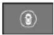 | Button lights up green: all Intelligent Safety systems are switched on. |
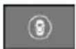 | Button lights up orange: some Intelligent Safety systems are switched off or settings for the sub-functions were changed. |
 | Button does not light up: all Intelligent Safety systems are switched off. |
Setting the warning time
About iDrive:
- "My Vehicle"
- "Vehicle settings"
- "Intelligent Safety"
- "Blind Spot Detection"
- Select desired setting.
"Off": With this setting, no warning is output.
The setting is stored for the drive profile currently used.
Set force of the steering wheel vibration
About iDrive:
- "My Vehicle"
- "Vehicle settings"
- "Steering wheel vibration"
- Select desired setting.
The setting is applied to all Intelligent Safety systems and stored for the profile currently used.
Vehicles with side collision warning: switching steering intervention on/off
The steering intervention can be switched on and off separately for Active Blind Spot Detection and lane departure warning.
About iDrive:
- "My Vehicle"
- "Vehicle settings"
- "Intelligent Safety"
- "Steering intervention"
The setting is stored for the drive profile currently used.
Issued warning
Lamp in the exterior mirror

natural_image
Close-up of a car side mirror and rearview panel, showing a black triangular pointer on the left side (no text or symbols visible)Information stage
The dimmed lamp in the exterior mirror indicates when there are vehicles in the blind spot or approaching from behind.
WARNING
If the turn signal is set while a vehicle is in the critical zone, the steering wheel vibrates briefly and the lamp in the exterior mirror flashes brightly.
Vehicles with side collision warning: it at speeds between 45 mph/70 km/h and 130 mph/210 km/h the vibrating steering wheel is ignored and the lane marking crossed, the system intervenes with a brief active steering intervention and helps to return the vehicle into the lane. The steering intervention can be noticed on the steering wheel and can be manually overridden at any time.
The warning stops when the turn signal is switched off, or the other vehicle leaves the critical zone.
Brief flashing of the lamp
A brief flashing of the lamp during vehicle un-locking serves as system self-test.
System limits
Functional limitations
The system may not be fully functional in the following situations:
When a vehicle is approaching at a speed much faster than your own.
▶ In heavy fog, rain or snowfall.
▶ In tight curves or on narrow lanes.
▶ If the bumper is dirty or iced up, or covered with stickers.
For vehicles with side collision warning, the steering intervention can be limited e.g. in the following situation:
In the event of missing, worn, poorly visible, merging, diverging, or multiple lane markings such as in construction areas.
▶ When lane markings are covered in snow, ice, dirt or water.
▶ When the lane markings are not white.
▶ When the lane markings are covered by objects.
▶ When driving very close to the vehicle in front of you.
▶ If there are constant blinding effects because of oncoming light, e. g., from the sun low in the sky.
When the windshield in front of the interior rearview mirror is fogged over, dirty or covered with stickers, etc.
During calibration of the camera immediately after vehicle delivery.
A Check Control message is displayed when the system is not fully functional.
Displaying warnings
Depending on the selected warning settings, e.g. warning time, more warnings can be displayed. However, there may also be an excess of premature warnings of critical vehicles.
For US owners only
The transmitter and receiver units comply with part 15 of the FCC/Federal Communication Commission regulations. Operation is governed by the following:
FCC ID:
NBG009014A.
Compliance statement:
This device complies with part 15 of the FCC Rules. Operation is subject to the following two conditions:
This device may not cause harmful interference, and
- this device must accept any interference received, including interference that may cause undesired operation.
Any unauthorized modifications or changes to these devices could void the user's authority to operate this equipment.
Side collision warning
The concept
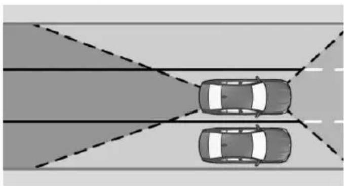
natural_image
Top-down view of two cars driving on a road with dashed lane markings (no text or symbols)The system helps to avoid imminent side collisions.
Four radar sensors in the bumpers monitor the area next to the vehicle in the speed range from approx. 45 mph/70 km/h to approx. 130 mph/210 km/h.
The front camera determines the lane marking positions.
If e.g. another vehicle is detected next to the vehicle and if there is a danger of collision with this vehicle, the system helps the driver to avoid the collision via steering intervention.
Information

WARNING
The system does not relieve from the personal responsibility to correctly assess visibility and traffic situation. There is risk of an accident. Adjust the driving style to the traffic conditions. Watch traffic closely and actively interfere in the respective situations.
Functional requirements
A prerequisite for activating the side collision warning with steering intervention is that the camera detects the lane markings.
Overview
Button in the vehicle
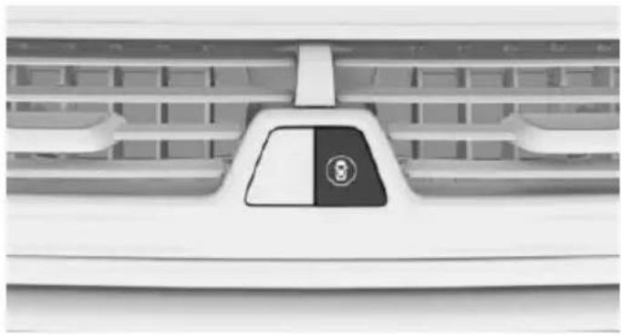
natural_image
Front view of a car air conditioner grille with a black and white panel showing the number 9 (no text or symbols visible)
Intelligent Safety
Radar sensors
The radar sensors are located in the bumpers.
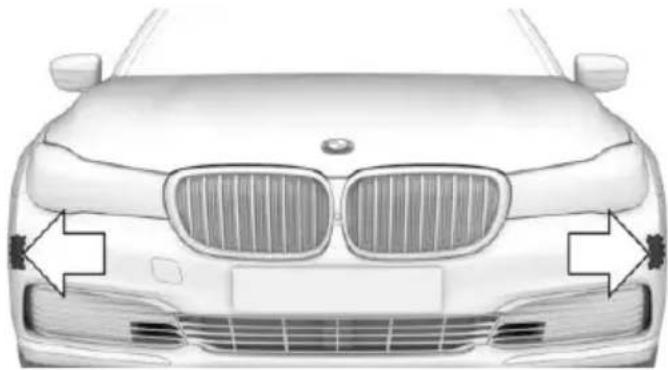
natural_image
Front view of a BMW car with grille grilles and side-mounted headlights (no text or symbols)Front side bumper.
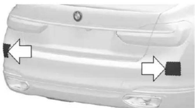
natural_image
Front view of a white car showing side bumper and side paint mark (no text or symbols)Rear bumper.
Always keep the bumper in the area of the radar sensors clean and unobstructed.
Camera
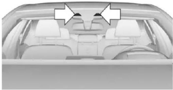
natural_image
Interior view of a car with white seats and two arrows pointing to the top section (no text or symbols visible)The camera is installed near the interior rear-view mirror.
Keep the windshield in the area behind the interior rearview mirror clean and clear.
Switching on/off
Switching on automatically
The side collision warning is automatically activated after departure, if the function was switched on the last time the engine was stopped.
Switching on/off manually
Press button:
The menu for the intelligent safety system is displayed.
If all Intelligent Safety systems were switched off, all systems are now switched on.
"Configure INDIVIDUAL": depending on the equipment version, the Intelligent Safety systems can be individually configured. The individual settings are activated and stored for the profile currently used. As soon as a setting is changed on the menu, all settings of the menu are activated, the button lights up orange.
Press button repeatedly. It is switched between the following settings:
"ALL ON" All Intelligent Safety systems are switched on. Basic settings are activated for the subfunctions.
"INDIVIDUAL": the Intelligent Safety systems are switched on according to the individual settings.
Some Intelligent Safety systems cannot be individually switched off.
Press and hold this button:
All Intelligent Safety systems are
turned off.
Press button
Status
Button lights up green: all Intelligent Safety systems are switched on.
Button lights up orange: some Intelligent Safety systems are switched off or settings for the sub-functions were changed.
Button does not light up: all Intelligent Safety systems are switched off.
Issued warning
Lamp in the exterior mirror
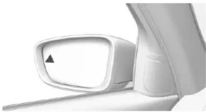
natural_image
Close-up of a car side mirror with a black triangular pointer on the left side (no text or symbols visible)WARNING
The lamp in the exterior mirror flashes and the steering wheel vibrates. An active steering intervention takes place to prevent collisions and maintain the vehicle within its own lane. The steering intervention can be noticed on the
steering wheel and can be manually overridden at any time.
System limits
The system may not be fully functional in the following situations:
When a vehicle is approaching at a speed much faster than your own.
In heavy fog, rain or snowfall.
In tight curves or on narrow lanes.
▶ If the bumpers are dirty or iced up, or covered with stickers.
In the event of missing, worn, poorly visible, merging, diverging, or multiple lane markings such as in construction areas.
When lane markings are covered in snow, ice, dirt or water.
When the lane markings are covered by objects.
When driving very close to the vehicle in front of you.
If there are constant blinding effects because of oncoming light, e. g., from the sun low in the sky.
When the windshield in front of the interior rearview mirror is fogged over, dirty or covered with stickers, etc.
During calibration of the camera immediately after vehicle delivery.
A Check Control message is displayed when the system is not fully functional.
For US owners only
The transmitter and receiver units comply with part 15 of the FCC/Federal Communication Commission regulations. Operation is governed by the following:
FCC ID:
NBG009014A.
Compliance statement:
This device complies with part 15 of the FCC Rules. Operation is subject to the following two conditions:
This device may not cause harmful interference, and
- this device must accept any interference received, including interference that may cause undesired operation.
Any unauthorized modifications or changes to these devices could void the user's authority to operate this equipment.
Rear collision prevention
The concept
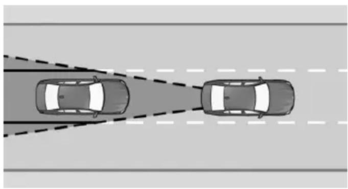
natural_image
Top-down diagram of two cars driving on a road with dashed lane markings (no text or symbols)Two radar sensors in the rear bumper monitor the area behind the vehicle.
If a vehicle approaches from the rear at a certain speed, the system responds as follows:
Active Protection: if a collision seems to be unavoidable, PreCrash functions are triggered.
The system is automatically active after every driving-off.
The system is deactivated in the following situations:
▶ If reverse gear is engaged
▶ If the trailer power socket is in use, e.g. during operation with trailer or bicycle rack
Information

WARNING
The system does not relieve from the personal responsibility to correctly assess visibility and traffic situation. There is risk of an accident. Adjust the driving style to the traffic conditions. Watch traffic closely and actively interfere in the respective situations.
Overview
Radar sensors
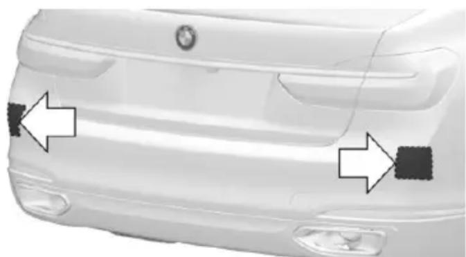
natural_image
Front view of a white car showing side-mounted black spots on the back, with no visible text or symbols.The radar sensors are located in the rear bumper.
Always keep the bumper in the area of the radar sensors clean and unobstructed.
System limits
The system may not be fully functional in the following situations:
▷ When a vehicle is approaching at a speed much faster than your own.
▶ In heavy fog, rain or snowfall.
In tight curves or on narrow lanes.
▶ If the bumper is dirty or iced up, or covered with stickers.
For US owners only
The transmitter and receiver units comply with part 15 of the FCC/Federal Communication Commission regulations. Operation is governed by the following:
FCC ID:
NBG009014A.
Compliance statement:
This device complies with part 15 of the FCC Rules. Operation is subject to the following two conditions:
This device may not cause harmful interference, and
- this device must accept any interference received, including interference that may cause undesired operation.
Any unauthorized modifications or changes to these devices could void the user's authority to operate this equipment.
Brake force display
The concept
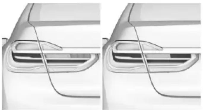
natural_image
Side-by-side comparison of a car's rear window and side panel, showing structural details (no text or symbols)During normal brake application, the outer brake lights light up.
During heavy brake application, the inner brake lights light up in addition.
Active Protection
The concept
Active Protection prepares occupants and the vehicle for a possible accident in critical driving or collision situations.
General information
Active Protection consists of various PreCrash functions, which can vary depending on the equipment.
The system is used to detect certain critical driving situations that might lead to an accident. Critical driving situations are:
Emergency stop.
▶ Severe understeering.
▶ Severe oversteering.
Certain functions of several systems can - within the system limits - lead to Active Protection triggering:
▶ Collision warning with braking function: detection of imminent front collisions or automatic braking intervention.
▶ Collision warning with braking function or Night Vision with Dynamic Marker Light: brake booster.
▶ Rear collision prevention: detection of imminent rear collisions.
Information

WARNING
The system does not relieve from the personal responsibility. Due to the system limits, critical situation could not be detected reliably or in time. There is risk of an accident. Adjust the driving style to the traffic conditions. Watch traffic closely and actively interfere in the respective situations.
Function
When the belt is closed, the driver's and passenger's belt straps are automatically tightened once after driving away.
In accident-critical situations, the following individual functions become active as needed:
The front belts are automatically preten-sioned.
▶ Automatic window closing up to a narrow gap.
▶ Automatic closing of the glass sunroof, including sliding visor.
For vehicles equipped with Comfort seats in the front: automatic positioning of the backrest for the front passenger seat.
For vehicles equipped with Comfort seats in the rear: automatic positioning of the backrests for the rear passenger seats.
After a critical driving situation without an accident, the front belts are loosened again. All other systems can be restored to the desired setting.
If the belt tension does not loosen automatically, stop the vehicle and unbuckle the belt using the red button in the buckle. Fasten the belt before continuing on your trip.
Post Crash — iBrake
The concept
In certain accident situations, e.g. collision, the system can bring the vehicle to a halt automatically without driver intervention. This can reduce the risk of a further collision and the consequences thereof.
At standstill
After coming to a halt, the brake is released automatically.
Harder vehicle braking
It can be necessary to bring the vehicle in certain situations to a halt quicker.
Here, a higher braking pressure must be generated for a short period when pressing the brake pedal than during automatic braking. This interrupts automatic braking.
Interrupting automatic braking
It can be necessary to interrupt automatic braking in certain situations, e.g. for an evasive maneuver.
Interrupt automatic braking:
▶ By pressing the brake pedal.
▶ By pressing the accelerator pedal.
Attentiveness assistant
The concept
The system can detect increasing lack of alertness or fatigue of the driver during long, monotonous journeys, e.g., on highways. In this situation, it is recommended that the driver takes a break.
Information

WARNING
The system does not relieve from the personal responsibility to correctly assess one's physical state. An increasing lack of alertness or fatigue may not be detected or not be detected in time. There is risk of an accident. Make sure that the driver is rested and alert. Adjust the driving style to the traffic conditions.
Function
The system is switched on each time drive readiness is switched on.
After travel has begun, the system is trained about the driver, so that increasing lack of alertness or fatigue can be detected.
This procedure takes the following criteria into account:
▶ Personal driving style, e.g., steering behavior.
▶ Driving conditions, e.g., length of trip.
Starting at approximately 43 mph/70 km/h, the system is active and can display a recommendation to take a break.
Break recommendation
Switching on/off, adjusting
The Attentiveness Assistant is active automatically with each switching on of drive readiness and can thus display a break recommendation.
The break recommendation can also be switched on or off via iDrive and adjusted:
About iDrive:
- "My Vehicle"
- "Vehicle settings"
- "Driver attention control"
- Select desired setting.
▶ "Off": no break recommendation is made.
▶ "Standard": the break recommendation is made with a defined value.
▶ "Sensitive": the break recommendation is issued earlier.
Display
If the driver becomes increasingly less alert or fatigued, a message is displayed in the Control Display with the recommendation to take a break.
During the display, the following settings can be selected:
▶ "Do not ask again"
▶ "Places to stop"
▶ "Remind me later"
The break recommendation is repeated after 20 minutes.
After a break, another recommendation to take a break cannot be displayed until after approximately 45 minutes.
System limits
The function may be limited in the following situations, for instance, and will either output an incorrect warning or no warning at all:
▶ When the clock is set incorrectly.
When the vehicle speed is mainly below about 43 mph/70 km/h.
▶ With a sporty driving style, such as during rapid acceleration or when cornering fast.
In active driving situations, such as when changing lanes frequently.
▶ When the road surface is poor.
▷ In the event of strong side winds.
Driving stability control systems
Vehicle features and options
This chapter describes all standard, country-specific and optional features offered with the series. It also describes features that are not necessarily available in your car, e.g., due to the selected options or country versions. This also applies to safety-related functions and systems. The respectively applicable country provisions must be observed when using the respective features and systems.
Anti-lock Braking System ABS
ABS prevents locking of the wheels during braking.
The vehicle contains its steering power even during full brake applications, thus increasing active safety.
ABS is operational every time you start the engine.
Brake assistant
When you apply the brakes rapidly, this system automatically produces the greatest possible braking force boost. It reduces the braking distance to a minimum during emergency stop. This system utilizes all of the benefits provided by ABS.
Do not reduce the pressure on the brake pedal for the duration of the emergency stop.
Adaptive brake assistant
In combination with the Active Cruise Control, this system ensures that the brakes respond even more rapidly when braking in critical situations.
Drive-off assistant
This system supports driving off on inclines. The parking brake is not required.
- Hold the vehicle in place with the foot brake.
- Release the foot brake and drive off without delay.
After the foot brake is released, the vehicle is held in place for approx. 2 seconds.
The possible holding duration amounts to 2 minutes.
Depending on the vehicle load or when a trailer is used, the vehicle may roll back slightly.
DSC Dynamic Stability Control
The concept
DSC prevents traction loss in the power wheels when driving off and accelerating.
DSC also recognizes unstable vehicle conditions such as fishtailing or nose-diving. Within the physical limits DSC helps to keep the vehicle on a steady course by reducing engine speed and by applying brakes to the individual wheels.
Information
Adapt your driving style to the situation, for an appropriate driving style is always the responsibility of the driver.
The laws of physics cannot be repealed, not even with DSC.
Therefore, do not reduce the additional safety margin by driving in a risky manner.

WARNING
When driving with roof load, e.g. with roof-mounted luggage rack, driving safety may not be ensured in driving-critical situations due to the elevated center of gravity. There is risk of accidents or risk of property damage. Do not deactivate Dynamic Stability Control DSC when driving with roof load.
Overview
Button in the vehicle
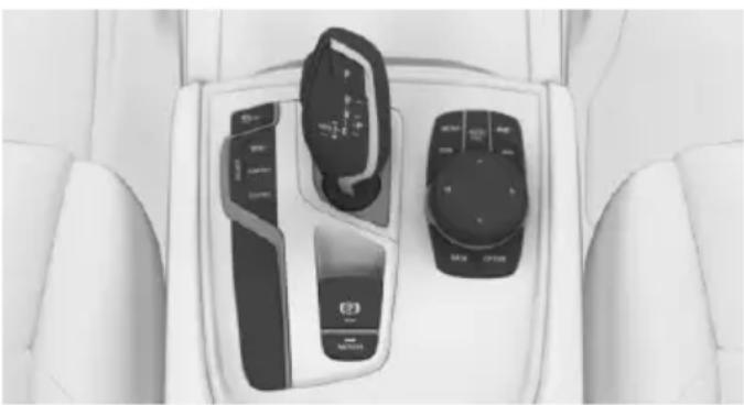
natural_image
Interior view of a car dashboard with control switches and buttons (no visible text or symbols)
DSC OFF
Indicator/warning lights

The indicator lamp flashes: DSC controls the drive and braking forces.
The indicator lamp lights up: DSC has
failed.
Deactivating/activating DSC
When DSC is deactivated, driving stability is reduced during acceleration and when driving in curves.
Stabilizing interventions by the Integral Active Steering system are only performed by the rear axle steering.
To increase vehicle stability, activate DSC again as soon as possible.
Deactivating DSC
Hold the button down until the DSC OFF indicator lamp is displayed in the instrument cluster and DSC OFF is displayed.
The DSC system is switched off.
The steering and, depending on the equipment, suspension are tuned for sporty driving.
Activating DSC
Press button.
DSC OFF and the DSC OFF indicator lamp go out.
Indicator/warning lights
When DSC is deactivated, DSC OFF is displayed in the instrument cluster.

The indicator lamp lights up: DSC is deactivated.
DTC Dynamic Traction Control
The concept
The DTC system is a version of the DSC where forward momentum is optimized.
The system ensures maximum headway on special road conditions or loose road surfaces, e.g., unplowed snowy roads, but with somewhat limited driving stability.
Activating the Dynamic Traction Control DTC provides maximum traction. Driving stability is limited during acceleration and when driving in curves.
Therefore drive with appropriate caution.
You may find it useful to briefly activate DTC under the following special circumstances:
▶ When driving in slush or on uncleared, snow-covered roads.
▶ When freeing vehicle from deep snow or driving off from loose grounds.
▶ When driving with snow chains.
Overview
Button in the vehicle
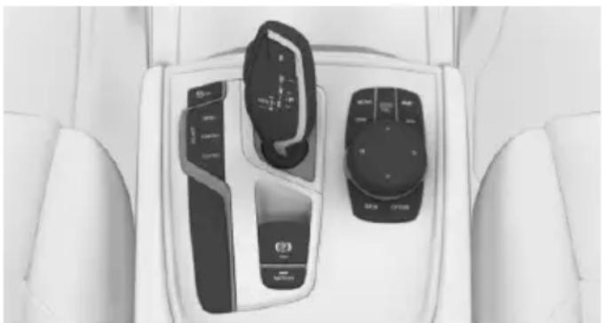
natural_image
Interior view of a car dashboard with two control switches and a digital display (no visible text or symbols)
DSC OFF
Indicator/warning lights
If DTC is activated, TRACTION is displayed in the instrument cluster.

The indicator lamp lights up: DTC Dynamic Traction Control is activated.
Activating/deactivating DTC
Activating DTC
Press button.
TRACTION is displayed in the instrument cluster and the indicator lamp for DSC OFF lights up.
Deactivating DTC
Press button again.
TRACTION and the DSC OFF indicator lamp go out.
xDrive
xDrive is the all-wheel-drive system of the vehicle. Concerted action by the xDrive and DSC further optimize traction and driving dynamics. The xDrive all-wheel-drive system variably distributes the drive forces to the front and rear axles as demanded by the driving situation and road surface.
HDC Hill Descent Control
The concept
HDC is a downhill driving assistant that automatically controls vehicle speed on steep downhill gradients. Without applying the brakes, the vehicle moves at slightly more than walking speed.
Hill Descent Control can be activated at speeds below approx. 22 mph/35 km/h. When driving downhill, the vehicle reduces its speed to approx. walking speed and then keeps its speed constant.
As long as there is active braking, the system is on standby. The system does not brake the vehicle during this time.
Only use HDC in low gears or in selector lever position D or R.
Increasing or decreasing vehicle speed
Specify desired speed in the range from approx. 4 mph/6 km/h to approx. 15 mph/25 km/h using the rocker switch of the cruise control on the steering wheel. Vehicle speed can be changed by lightly accelerating.
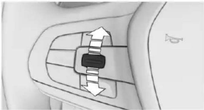
natural_image
Diagram of a car's side panel showing bidirectional arrows indicating movement or force (no text or symbols)▶ Press the rocker switch up to the point of resistance: the speed increases gradually.
▶ Press up the rocker switch past the point of resistance: the speed increases while the rocker switch is pressed.
▶ Press the rocker switch down to the point of resistance: the speed decreases gradually.
▶ Press the rocker switch down past the point of resistance: when driving forward, the speed decreases to approx. 6 mph/10 km/h; when reversing, the speed decreases to approx. 4 mph/6 km/h.
Overview
Button in the vehicle
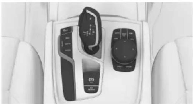
natural_image
Interior view of a car dashboard with control panels and a touchscreen display (no visible text or symbols)
HDC
Activating HDC

Press button. The LED above the button lights up.
Deactivating HDC

Press button again and the LED goes out. HDC is automatically deactivated e approx. 37 mph/60 km/h.
Display in the instrument cluster
Status display
A symbol and the selected desired speed are displayed.
The desired speed is hidden after a brief time.
With a change of the desired speed via the rocker switch on the steering wheel, it is displayed briefly.
Desired speed
Display in the speedometer:
▷ Green marking: system is active.
▶ Marking is orange/white: the system has been paused.
No marking: system is switched off.
Malfunction
A message is displayed in the instrument cluster. HDC is not available, e.g., due to elevated brake temperatures.
Integral Active Steering
The concept
Integral Active Steering is a combination of Active Steering and rear axle steering.
The system varies the steering angle of the wheels in relation to the steering wheel movement.
With strong steering movements and low speeds, e.g. when parking, the wheel angle is magnified, that is, the steering is more direct.
The rear axle steering acts to increase maneuverability by turning the rear wheels slightly in a direction opposite to the front wheels.
At higher speeds, the rear wheels are turned in the same direction as the front wheels.
In critical driving situations, the Integral Active Steering can stabilize the vehicle through purposeful steering of the rear wheels before the driver intervenes, e.g. in case of oversteering.
General information
The system offers several different tunings.
These are assigned to the different driving modes of the Driving Dynamics Control, refer to page 110.
Tuning
Drive mode Integral Active Steering
COMFORT/E comfortable, for optimal CO PRO travel comfort
SPORT dynamic, for greater agility
Using snow chains
Information
When snow chains are in use, refer to page 264, rear wheel steering is deactivated.
Malfunction
In the event of a malfunction, the steering wheel must be turned further, while the vehicle responds more sensitively to steering wheel movements in the higher speed range.
The stability-enhancing intervention may be deactivated.
Proceed cautiously and drive defensively. Have the system checked.
Driver assistance systems
Vehicle features and options
This chapter describes all standard, country-specific and optional features offered with the series. It also describes features that are not necessarily available in your car, e.g., due to the selected options or country versions. This also applies to safety-related functions and systems. The respectively applicable country provisions must be observed when using the respective features and systems.
Active Cruise Control with Stop & Go function, ACC
The concept
Use this system to select a desired speed that the vehicle will maintain automatically on clear roads.
To the extent possible, the system automatically adjusts the speed to a slower vehicle ahead of you.
The distance that the vehicle maintains to the vehicle ahead of you can be varied. For safety reasons, it depends on the speed.
To maintain a certain distance, the system automatically reduces the speed, applies the brakes lightly, or accelerates again if the vehicle ahead begins moving faster.
If the vehicle ahead of you brakes to a halt, and then proceeds to drive again within a brief period, the system is able to detect this within the given system limits. Your own vehicle will brake automatically and then accelerate again.
If the vehicle ahead of you drives away again after a prolonged period, briefly press the accelerator pedal or press the appropriate button to reactivate the system. The vehicle will automatically accelerate.
As soon as the road is clear, the vehicle accelerates to the desired speed.
Vehicles driving ahead are captured by a radar sensor and a camera.
General information
Depending on the driving settings, the features of the cruise control can change in certain areas.
The desired speed is also maintained downhill, but may not be maintained on uphill grades if engine power is insufficient.
Due to the driving style that minimizes fuel consumption in ECO PRO drive mode, the vehicle may drop below the set desired speed in some situations, e.g. on uphill grades.
Information

WARNING
The system does not relieve from the personal responsibility to correctly assess the traffic situation. Based on the limits of the system, it cannot independently react to all traffic situations. There is risk of an accident. Adjust the driving style to the traffic conditions. Watch traffic closely and actively interfere in the respective situations.

WARNING
An unsecured vehicle can put itself into motion and roll away. There is risk of an accident. Before exiting, secure the vehicle against rolling.
In order to ensure that the vehicle is secured against rolling away, observe the following:
▷ Set the parking brake.
On uphill grades or on a slope, turn the front wheels in the direction of the curb.
On uphill grades or on a slope, also secure the vehicle, e.g. with a wheel chock.
Overview
Buttons on the steering wheel
| Press button | Function |
 | Cruise control on/off, refer to page 169. |
 | Store/maintain speed, refer to page 170. |
 | Pause cruise control, refer to page 170.Continue cruise control with the last setting, refer to page 171. |
 | Without steering and lane guidance assistant:Increase distance, refer to page 171. |
 | Without steering and lane guidance assistant:Reduce distance, refer to page 171. |
 | With steering and lane guidance assistant:Adjust distance, refer to page 171. |
 | Rocker switch:Maintain, store, change speed, refer to page 170. |
 | With steering and lane guidance assistant:Steering and lane guidance assistant including Traffic Jam Assist on/off, refer to page 177. |
Radar sensor
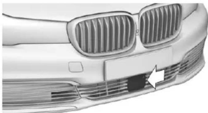
natural_image
Front view of a car's head and grille with a white arrow pointing to a specific grille (no text or symbols visible)The radar sensor is located in the front bumper.
Always keep radar sensor clean and unobstructed.
Camera
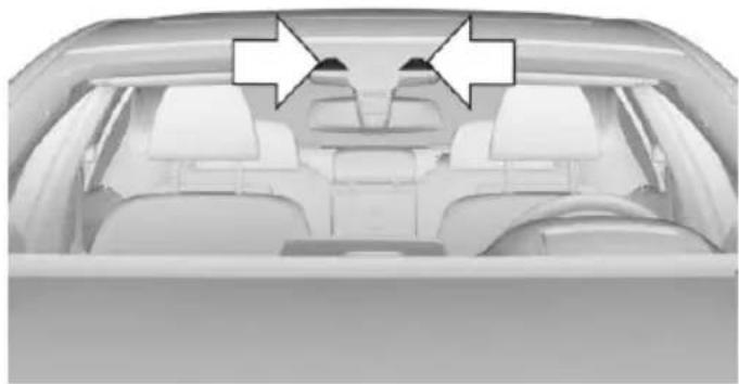
natural_image
Interior view of a car showing the rear seats and dashboard (no text or symbols visible)The camera is installed near the interior rear-view mirror.
Keep the windshield in the area behind the interior rearview mirror clean and clear.
Switching on/off and interrupting cruise control
Switching on
Press button on the steering wheel.
The indicator lights in the instrument cluster light up and the mark in the speedometer is set to the current speed.
Cruise control is active.
DSC Dynamic Stability Control will be switched on if needed.
Switch off
To switch off the system while standing, step on brake pedal at the same time.
Press button on the steering wheel.
The displays go out. The stored desired speed is deleted.
Interrupting
When active, press the button on the steering wheel.
If interrupting the system while stationary, press on the brake pedal at the same time.
The system is automatically interrupted in the following situations:
When the brakes are applied.
▶ When selector lever position D is disengaged.
When DTC Dynamic Traction Control is activated or DSC is deactivated.
When DSC is actively controlling stability.
If the safety belt and the driver's door are opened while the vehicle is standing still.
If the system has not detected objects for an extended period, e.g., on a road with very little traffic without curb or shoulder markings.
▶ If the detection range of the radar is disrupted, e.g., by dirt or heavy fog.
▶ After a longer stationary period when the vehicle has been braked to a stop by the system.
Maintaining, storing, and changing the speed
Information

WARNING
The desired speed can be incorrectly adjusted or called up by mistake. There is risk of an accident. Adjust the desired speed to the
traffic conditions. Watch traffic closely and actively interfere in the respective situations.

WARNING
Risk of accident due to too high speed differences to other vehicles, e.g. in the following situations:
When fast approaching a slowly moving vehicle.
▶ Suddenly swerving vehicle onto the own lane.
When fast approaching standing vehicles.
There is risk of injuries or danger to life. Watch traffic closely and actively interfere in the respective situations.
Maintaining/storing the speed
Press button.
Or:
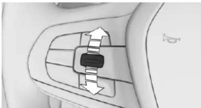
natural_image
Diagram of a car seatbelt mechanism with directional arrows indicating movement (no text or symbols)Press the rocker switch while the system is interrupted.
When the system is switched on, the current speed is maintained and stored as the desired speed.
This is displayed in the speedometer and briefly in the instrument cluster, refer to page 172.
DSC Dynamic Stability Control will be switched on if needed.
Changing the speed
Press the rocker switch up or down repeatedly until the desired speed is set.
If active, the displayed speed is stored and the vehicle reaches the stored speed when the road is clear.
▶ Each time the rocker switch is pressed to the resistance point, the desired speed increases or decreases by 1 mph/1 km/h.
▶ Each time the rocker switch is pressed past the point of resistance, the desired speed increases or decreases by a maximum of 5 mph/10 km/h.
Hold the rocker switch in position to repeat the action.
Distance

WARNING
The system does not relieve from the personal responsibility. Due to the system limits, braking can be late. There is risk of accidents or risk of property damage. Be aware to the traffic situation at all times. Adjust the distance to the traffic and weather conditions and maintain the prescribed safety distance, possibly by braking.
Without steering and lane guidance assistant: reducing distance

Press button repeatedly until the desired distance is set.
Instrument cluster will display selected distance, refer to page 172.
Without steering and lane guidance assistant: increasing distance
Press button repeatedly until the desired distance is set.
Instrument cluster will display selected distance, refer to page 172.
With steering and lane guidance assistant: adjusting distance
Press button repeatedly until the desired distance is set.
Continuing cruise control
General information
Press button with the system inter- rupted.
The stored speed is reached and maintained.
In the following cases, the stored speed value is deleted and cannot be called up again:
▶ When the system is switched off.
▶ When drive readiness is switched off.
While standing
The system brought the vehicle to a complete standstill:
▷ Green marking in the speedometer:
Your vehicle accelerates automatically as soon as the vehicle in the range of the radar sensor moves off.
▶ Speedometer markings turn orange/white after a short time: no automatic driving off.

By pressing the button, the time in which there is automatic driving off is d.
Vehicle symbol in the distance indicator is moving away: detected vehicle drove off.
The system was paused or your vehicle was brought to a halt actively through stepping on the brake pedal and it is standing behind another vehicle:
RES
1. Press button to call up a stored desired speed.
2. Release the brake pedal.
3. When the vehicle in front drives off:
▶ briefly press the gas pedal.
Press button.
Press button
▶ Press the rocker switch.
Displays in the instrument cluster
Desired speed
Display in the speedometer:
▷ Green marking: system is active.
▶ Marking is orange/white: the system has been paused.
No marking: system is switched off.
Status display

The selected desired speed is hidden after a brief time.
If no speed is indicated, it is possible that the conditions necessary for operation are not currently fulfilled.
Distance to vehicle ahead of you
Shown is selected distance to the vehicle driving ahead of you.
Symbol Description
Distance 1
Distance 2
Symbol Description

Distance 3
Distance 4
This value is set automatically after the system is switched on.
System interrupted.
Distance control suppressed briefly because the gas pedal is pressed.
Vehicle symbol in the distance indicator is moving away: detected vehicle drove off. ACC is no longer accelerating. To accelerate further, activate ACC by briefly stepping on the accelerator pedal or pressing the rocker switch.
Indicator/warning lights
Symbol Description
Green symbols:
A vehicle has been detected ahead of you. The system maintains the set distance to the vehicle in front.
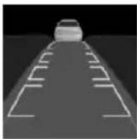
Vehicle symbol flashes:
The conditions are not adequate for the system to work.
The system was deactivated but applies the brakes until you actively resume control by pressing on the brake pedal or accelerator pedal.
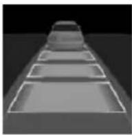
The vehicle symbol and distance bars flash red and an acoustic signal sounds:
You are requested to intervene by braking or make an evasive maneuver.
Displays in the Head-up Display
With Active Cruise control, some system information can also be displayed in the Head-up Display.

The symbol is displayed on the Head-up Display if the set desired speed is reached.
Distance information

The symbol is displayed when the distance from the vehicle traveling ahead is too short.
The distance information is active under the following circumstances:
Active Cruise Control switched off.
▶ Display in the Head-up Display selected, refer to page 126.
Distance too short.
▶ Speed greater than approx. 40 mph/70 km/h.
System limits
Speed range
The system is best used on well-constructed roads.
The minimum speed that can be set is 20 mph/30 km/h.
The maximum speed that can be set is 115 mph/180 km/h.
The system can also be activated when stationary.
Comply with the legal speed limit in every situation when using the system.
Detection range
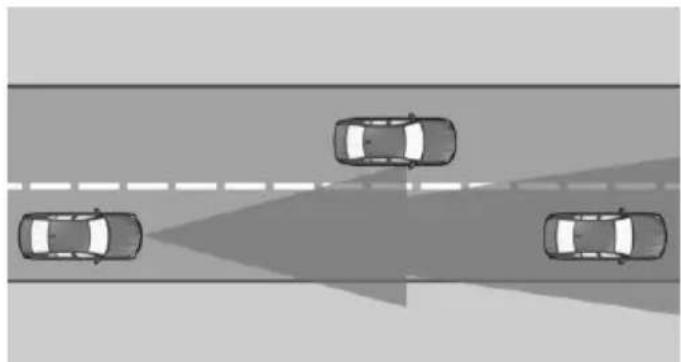
natural_image
Top-down view of four cars driving on a road with a shaded lane (no text or symbols)The detection capacity of the system and the automatic braking capacity are limited.
Two-wheeled vehicles for instance might not be detected.
Deceleration
The system also does not decelerate in the following situations:
▶ For pedestrians or similar slow-moving road users.
For red traffic lights.
For cross traffic.
▶ For oncoming traffic.
Swerving vehicles
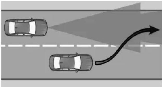
natural_image
Top-down diagram of two cars driving on a road with an arrow indicating direction (no text or symbols)A vehicle driving in front of you is not detected until it is completely within the same lane as your vehicle.
If a vehicle driving ahead of you suddenly swerves into your lane, the system may not be able to automatically restore the selected distance. This also applies to major speed differences to vehicles driving ahead of you, e.g., when rapidly approaching a truck. When a vehicle driving ahead of you is reliably detected, the system requests that the driver intervene by braking and carrying out evasive maneuvers, if needed.

WARNING
The system does not relieve from the personal responsibility to correctly assess the traffic situation. Based on the limits of the system, it cannot independently react to all traffic situations. There is risk of an accident. Adjust the driving style to the traffic conditions. Watch traffic closely and actively interfere in the respective situations.
Cornering
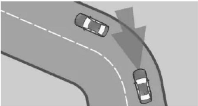
natural_image
Top-down view of three cars driving on a curved road with dashed lane markings (no text or symbols)If the desired speed is too high for a curve, the speed is reduced slightly, although curves cannot be anticipated in advance. Therefore, drive into a curve at an appropriate speed.
In tight curves the system offers only restricted detection where a vehicle ahead of you might be detected late or not at all.
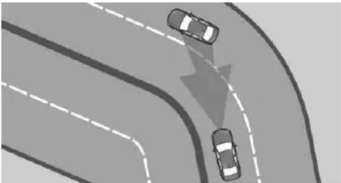
natural_image
Top-down view of a multi-lane road with two cars driving, one moving toward the center and another falling (no text or symbols)When you approach a curve the system may briefly report vehicles in the next lane due to the bend of the curve. If the system decelerates you may compensate it by briefly accelerating.
After releasing the gas pedal the system is re-activated and controls speed independently.
Driving away
In some situations, the vehicle cannot drive off automatically; for example:
On steep inclines.
From behind bumps in the road.
In these cases, step on the accelerator pedal.
Weather
In the event of unfavorable weather and light conditions, e. g. if there is rain, snowfall, slush, fog or glare, this may result in poorer recognition of vehicles as well as short-term interruptions for vehicles that are already detected. Drive attentively, and react to the current traffic situation. If necessary, intervene actively, e.g. by braking, steering or evading.
Radar sensor
For US owners only
The transmitter and receiver units comply with part 15 of the FCC/Federal Communication Commission regulations. Operation is governed by the following:
FCC ID:
OAYARS3-A
Compliance statement:
This device complies with part 15 of the FCC Rules. Operation is subject to the following two conditions:
This device may not cause harmful interference, and
- this device must accept any interference received, including interference that may cause undesired operation.
Any unauthorized modifications or changes to these devices could void the user's authority to operate this equipment.
Malfunction
The system cannot be activated if the radar sensor is not aligned correctly. This may be caused by damage incurred during parking, e.g.
A Check Control message is displayed if the system fails.
The function for detecting and responding when approaching stationary vehicles may be limited in the following situations:
During calibration of the camera immediately after vehicle delivery.
▶ If the camera is malfunctioning or dirty. A Check Control message is displayed.
Cruise control
The concept
The system maintains a preset speed via the buttons on the steering wheel. The system brakes on downhill gradients if engine braking is insufficient.
General information
Depending on the driving settings, the features of the cruise control can change in certain areas.
The desired speed is also maintained downhill, but may not be maintained on uphill grades if engine power is insufficient.
Due to the driving style that minimizes fuel consumption in ECO PRO drive mode, the vehicle may drop below the set desired speed in some situations, e.g. on uphill grades.
Information

WARNING
The use of the system can lead to an increased risk of accidents in the following situations:
On winding roads.
In heavy traffic.
On slippery roads, in fog, snow or rain, or on a loose road surface.
There is risk of accidents or risk of property damage. Only use the system if driving at constant speed is possible.
Overview
Buttons on the steering wheel
| Press button | Function |
 | Cruise control on/off, refer to page 176. |
 | Store/maintain speed, refer to page 176. |
 | Pause cruise control, refer to page 176.Continue cruise control, refer to page 177. |
 | Rocker switch:Maintain, store, change speed, refer to page 177. |
Controls
Switching on
Press button on the steering wheel.
The indicator lights in the instrument cluster light up and the mark in the speedometer is set to the current speed.
Cruise control is active.
DSC Dynamic Stability Control will be switched on if needed.
Switch off

WARNING
The system does not relieve from the personal responsibility to correctly assess the traffic situation. Based on the limits of the system, it cannot independently react to all traffic situations. There is risk of an accident. Adjust the driving style to the traffic conditions. Watch traffic closely and actively interfere in the respective situations.
Press button on the steering wheel.
The displays go out. The stored desired speed is deleted.
Interrupting
When active, press the button.
The system is automatically interrupted in the following situations:
When the brakes are applied.
▶ If selector lever position D is disengaged.
▶ If DTC Dynamic Traction Control is activated or DSC is deactivated.
When DSC is actively controlling stability.
Maintaining, storing, and changing the speed
Information

WARNING
The desired speed can be incorrectly adjusted or called up by mistake. There is risk of an accident. Adjust the desired speed to the traffic conditions. Watch traffic closely and actively interfere in the respective situations.
Maintaining/storing the speed
Press button.
Or:
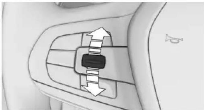
natural_image
Diagram of a car's side panel with directional arrows indicating movement (no text or symbols)Press the rocker switch while the system is interrupted.
When the system is switched on, the current speed is maintained and stored as the desired speed.
This is displayed, refer to page 177, in the speedometer and briefly in the instrument cluster.
DSC Dynamic Stability Control will be switched on if needed.
Changing the speed
Press the rocker switch up or down repeatedly until the desired speed is set.
If active, the displayed speed is stored and the vehicle reaches the stored speed when the road is clear.
▶ Each time the rocker switch is pressed to the resistance point, the desired speed increases or decreases by 1 mph/1 km/h.
▶ Each time the rocker switch is pressed past the point of resistance, the desired speed increases or decreases by a maximum of 5 mph/10 km/h.
The maximum speed that can be set depends on the vehicle.
▶ Pressing the rocker switch to the resistance point and holding it accelerates or decelerates the vehicle without requiring pressure on the accelerator pedal.
After the rocker switch is released, the vehicle maintains its final speed. Pressing the switch beyond the resistance point causes the vehicle to accelerate more rapidly.
Continuing cruise control
Press button while the system is inter- rupted.
The stored speed is reached and maintained.
Displays in the instrument cluster
Desired speed
Display in the speedometer:
▷ Green marking: system is active.
▶ Marking is orange/white: the system has been paused.
▶ No marking: system is switched off.
Indicator lamp

Indicator lamp green: system is active.
Gray indicator lamp: the system has been paused.
No indicator lamp: system is switched off.
Status display

The selected desired speed is hidden after a brief time.
If no speed is indicated, it is possible that the conditions necessary for operation are not currently fulfilled.
Displays in the Head-up Display
Some system information can also be displayed in the Head-up Display.

The symbol is displayed on the Head-up Display if the set desired speed is reached.
Steering and lane guidance assistant including Traffic Jam Assist
The concept
The system assists the driver in keeping the vehicle within the lane. For this purpose, the system steers independently, e.g., when driving in a curve.
Depending on the speed, the system orients itself according to the lane markings or vehicles in front.
General information
The system determines the position of the lane markings and the vehicle driving ahead using five radar sensors and a camera.
Sensors on the steering wheel detect whether the steering wheel is being touched.
In order to be able to use the system, place your hands around the steering wheel.
The system is deactivated if the steering wheel is no longer being touched.
Information

WARNING
The system does not relieve from the personal responsibility to correctly assess the traffic situation. Based on the limits of the system, it cannot independently react to all traffic situations. There is risk of an accident. Adjust the driving style to the traffic conditions. Watch traffic closely and actively interfere in the respective situations.
Overview
Button the steering wheel
Switch steering and lane guidance assistant including Traffic Jam Assist on/off, refer to page 179.
Radar sensors
The radar sensors are located in the bumpers.
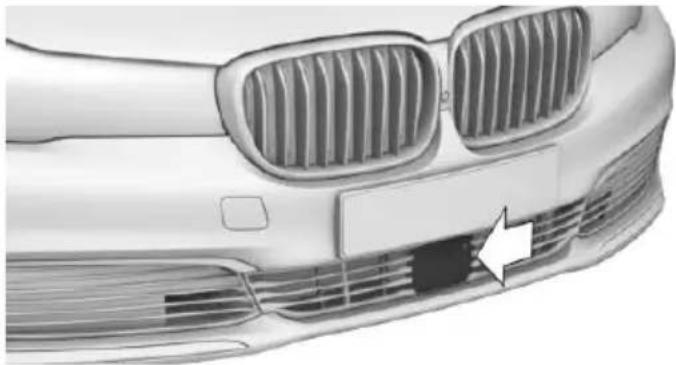
natural_image
Front view of a car's head and grille with visible grating and ventilation grilles (no text or symbols)Front center bumper
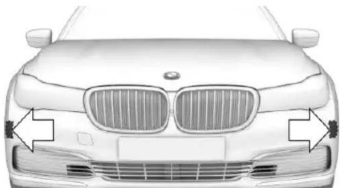
natural_image
Front view of a BMW car with grille and side brackets (no text or symbols)Front side bumper
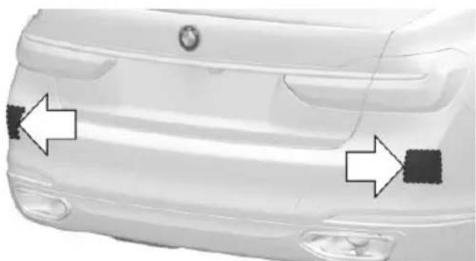
natural_image
Front view of a white car showing side and rear bumper areas with directional arrows (no text or symbols)Rear bumper
Always keep the bumper in the area of the radar sensors clean and unobstructed.
Camera
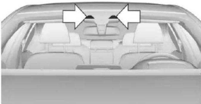
natural_image
Interior view of a car showing rear seats and dashboard (no visible text or symbols)The camera is installed near the interior rear-view mirror.
Keep the windshield in the area behind the interior rearview mirror clean and clear.
Functional requirements
▶ Speed below 130 mph/210 km/h.
▶ Sufficient lane width.
▶ Above approx. 43 mph, 70 km/h: lane marking on both sides is detected.
Below approx. 43 mph, 70 km/h: lane marking on both sides or a vehicle driving ahead is detected.
- At least one hand on the steering wheel rim.
▶ Wide curves.
▶ Drive in the center of the lane.
▶ Turn signal not actuated.
▶ Camera calibration immediately after vehicle delivery is completed.
Switching on/off
Switching on

Press button on the steering wheel.

Steering wheel symbol lights up gray.
System activates automatically as soon as all function conditions are fulfilled, refer to page 179.

Steering wheel symbol lights up green.
The system is active.
With the system switched on, pedestrian warning and side collision warning are active. Settings on the Control Display remain unchanged.
Switch off
Press button on the steering wheel.
The indicator goes out.
The system does not manipulate steering.
Automatic interruption
The system is automatically interrupted in the following situations:
At a speed above 130 mph/210 km/h.
When the steering wheel is released.
▷ When you manipulate steering.
▷ When you leave your own lane.
When the turn signal is on.
When the lane is too narrow.
If for a particular time no lane marking is detected and there is no vehicle driving in front.

Steering wheel symbol lights up gray. The system is paused and does not manipulate steering.
If the system conditions are met, the system reactivates automatically.
Displays in the instrument cluster
Symbol Description

Steering wheel symbol gray: the system is on standby.

Steering wheel symbol green: system activated.
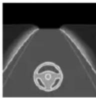
Steering wheel symbol and lane marking green: the system assists the driver in keeping the vehicle within the lane.
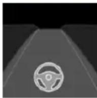
Steering wheel symbol green, lane marking gray: no lane marking detected. The vehicle follows the vehicle in front.

Steering wheel symbol yellow: hold steering wheel. The system is still active.
Steering wheel symbol red and a signal tone sounds: system interrupted. It does not manipulate steering.
Displays in the Head-up Display
All system information can also be displayed in the Head-up Display.
System limits
When driving with gloves or with protective covers, contact with the steering wheel cannot be detected by the sensors. In this case system cannot be used.
When driving within narrow lanes, the system cannot be activated or meaningfully used.
Do not use the system, e.g.:
In construction zones.
In rescue lanes.
▶ Within city limits.
Weather
In the event of unfavorable weather and light conditions, e. g. if there is rain, snowfall, slush, fog or glare, this may result in poorer recognition of vehicles as well as short-term interruptions for vehicles that are already detected. Drive attentively, and react to the current traffic situation. If necessary, intervene actively, e.g. by braking, steering or evading.
PDC Park Distance Control
The concept
PDC is a support when parking. Objects that you are approaching slowly in front of or behind the vehicle are indicated with:
▷ Signal tones.
▷ Visual display.
With parking assistant: obstacles on the side of the vehicle that are detected by the sensors of the parking assistant, can also be reported by the PDC. Side protection, refer to page 183.
General information
Ultrasound sensors in the bumpers and possibly sideways on the vehicle measure the distances from objects.
The maneuvering range, depending on the obstacle and environmental conditions, is approx. 6 ft/2 m.
An acoustic warning is first given with the following circumstances:
By the front center sensors at approx. 74 in/70 cm.
By the rear middle sensors at approx. 5 ft/1.50 m.
▶ By the corner sensors at approx. 24 in/60 cm.
▶ With parking assistant: by the side sensors at approx. 24 in/60 cm.
▶ When a collision is imminent.
Information

WARNING
The system does not relieve from the personal responsibility to correctly assess the traffic situation. Based on the limits of the system, it cannot independently react to all traffic situations. There is risk of an accident. Adjust the driving style to the traffic conditions. Watch traffic closely and actively interfere in the respective situations.

WARNING
Due to high speeds when PDC is activated, the warning can be delayed due to physical circumstances. There is risk of injuries or risk of property damage. Avoid approaching an object too fast. Avoid driving off fast while PDC is not yet active.
Overview
Button in the vehicle
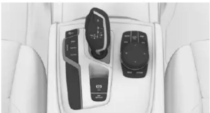
natural_image
Interior view of a car dashboard with control switches and buttons (no visible text or symbols)
PDC Park Distance Control
Ultrasound sensors

Ultrasound sensors of the PDC, e.g. in the bumpers.
Functional requirements
To ensure full functionality:
Do not cover sensors, e.g., with stickers, bicycle racks.
▷ Keep the sensors clean and free of ice.
To clean: when using high-pressure washers, do not spray the sensors for long periods and maintain a distance of at least 12 in/30 cm.
Switching on/off
Switching on automatically
PDC switches on automatically in the following situations:
▶ If selector lever position R is engaged when the engine is running.
▶ While approaching detected obstacles if the speed is slower than approx.
2.5 mph/4 km/h. The activation distance depends on the situation in question.
You may switch on and off automatic activation when obstacles are detected.
About iDrive:
- "My Vehicle"
- "Vehicle settings"
- "Parking"
- "Automatic PDC activation": only with respective equipment.
- "Automatic PDC activation"
The setting is stored for the drive profile currently used.
Depending on equipment, an appropriate camera view is also switched on.
Automatic deactivation during forward travel
The system switches off when a certain driving distance or speed is exceeded.
Switch the system back on if needed.
Switching on/off manually

Press button.
On: the LED lights up.
▶ Off: the LED goes out.
The rearview camera image is displayed when the reverse gear is engaged by pressing the button.
Display
Signal tones
When approaching an object, an intermittent sound indicates the position of the object. E. g. if an object is detected to the left rear of the vehicle, a signal tone sounds from the left rear speaker.
The shorter the distance to the object, the shorter the intervals.
If the distance to a detected object is less than approx. 10 in/25 cm, a continuous tone is sounded.
If there are objects in front of and behind the vehicle at the same time, with a distance smaller than approx. 10 in/25 cm, an alternating constant tone will sound.
The interval tone and constant tone are switched off if the selector lever position P is engaged.
The interval tone is switched off after a short time when the vehicle is stationary.
Volume
The ratio of the PDC signal tone volume to the entertainment volume can be adjusted.
About iDrive:
- "My Vehicle"
- "System settings"
- "Tone"
-
"Volume settings"
-
"PDC"
- Set the desired value.
The setting is stored for the drive profile currently used.
Visual warning
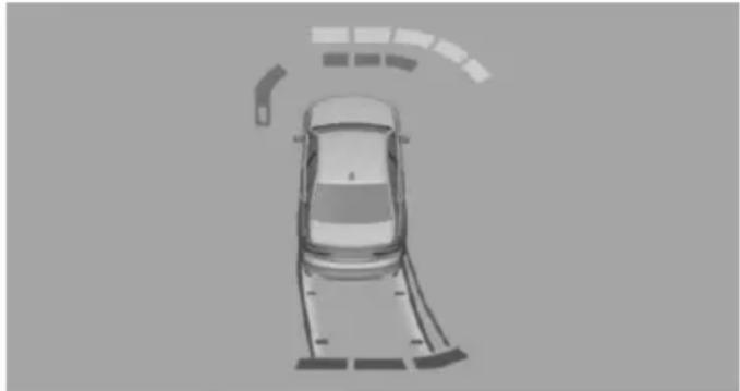
natural_image
Top-down view of a car with curved roof and parking structure (no text or symbols)The approach of the vehicle to an object is shown on the Control Display. Objects that are farther away are already displayed on the Control Display before a signal sounds.
The display appears as soon as PDC is activated.
The range of the sensors is represented in the colors green, yellow and red.
Pathway lines are faded in for better estimation of the required space.
When the image of the rearview camera is displayed, the switch can be made to PDC or to a different view with obstacle markings as needed:
"Rear view camera"
Cross traffic warning, refer to page 197: depending on the equipment, it is warned in the PDC display against vehicles approaching in the front or rear from the side.
With parking assistant: emergency braking function, Active PDC
The concept
The emergency braking function of PDC initiates an emergency braking in case of acute risk of collision. Due to system limits, a colli-
sion cannot be prevented under all circumstances.
The function is available from walking speed while backing up or rolling backward.
A press of the gas pedal interrupts the braking intervention.
After emergency braking to a stop, further creeping toward an obstacle is possible. To creep toward the obstacle, lightly press the accelerator pedal and release it again.
If the accelerator pedal is heavily depressed, the vehicle drives off as usual. Manual braking is possible at any time.
General information
The system uses the ultrasound sensors of PDC and parking assistant.
Information

WARNING
The system does not relieve from the personal responsibility to correctly assess the traffic situation. There is risk of an accident. Adjust the driving style to the traffic conditions. Watch traffic and vehicle surroundings closely and actively interfere in the respective situations.
Activating/deactivating the system
About iDrive:
- "My Vehicle"
- "Vehicle settings"
- "Parking"
- "Active PDC emergency brake function"
- "Active PDC emergency brake function"
The setting is stored for the drive profile currently used.
With parking assistant: side protection
The concept
Obstacles on the side of the vehicle are detected by the sensors of the system. The system warns against these obstacles.
Display
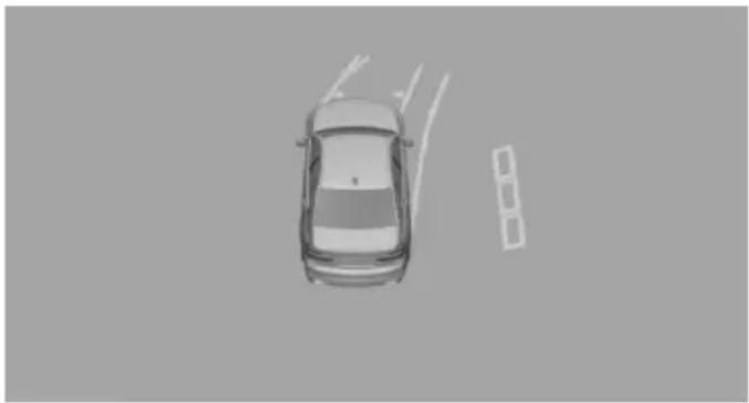
natural_image
Top-down view of a car on a road with visible lane markings (no text or symbols)Obstacle markings are displayed sideways on the vehicle to protect the vehicle sides.
▶ Gray markings: the area next to the vehicle was not captured.
▶ No markings: no obstacles were detected.
▶ Color markings: warning against detected obstacles.
Limits of side protection
The system only displays stationary obstacles that were previously detected by sensors while passing them.
The system does not detect, whether an obstacle moves later on. For this reason, at standstill, the markings are shown in the display in gray after a certain time. The area next to the vehicle must be newly captured.
System limits
Limits of ultrasonic measurement
Ultrasonic measuring might not function under the following circumstances:
▶ For small children and animals.
▶ For persons with certain clothing, e.g. coats.
▶ With external interference of the ultrasound, e.g. from passing vehicles or loud machines.
▶ When sensors are dirty, iced over, damaged or out of position.
▶ Under certain weather conditions such as high relative humidity, rain, snowfall, extreme heat or strong wind.
▶ With tow bars and trailer couplings of other vehicles.
▶ With thin or wedge-shaped objects.
▶ With moving objects.
▶ With elevated, protruding objects such as ledges or cargo.
▶ With objects with corners and sharp edges.
▶ With objects with a fine surface structure such as fences.
▶ For objects with porous surfaces.
Low objects already displayed, e.g., curbs, can move into the blind area of the sensors before or after a continuous tone sounds.
Cargo that extends beyond the perimeter of the vehicle is not taken into account by the system.
False warnings
PDC may issue a warning under the following conditions even though there is no obstacle within the detection range:
▷ In heavy rain.
▶ When sensors are very dirty or covered with ice.
▶ When sensors are covered in snow.
On rough road surfaces.
On uneven surfaces, such as speed bumps.
In large buildings with right angles and smooth walls, e.g., in underground garages.
In automatic car washes.
▶ Through heavy pollution.
▶ Due to other ultrasound sources, e.g., sweeping machines, high pressure steam cleaners or neon lights.
Malfunction
A Check Control message is displayed.

White symbol is displayed, and the range of the sensors is dimmed on the Control Display.
PDC has failed. Have the system checked.
Without Surround View: rearview camera
The concept
The rearview camera provides assistance in parking and maneuvering backwards. The area behind the vehicle is shown on the Control Display.
Information

WARNING
The system does not relieve from the personal responsibility to correctly assess the traffic situation. There is risk of an accident. Adjust the driving style to the traffic conditions. Watch traffic and vehicle surroundings closely and actively interfere in the respective situations.
Overview
Button in the vehicle
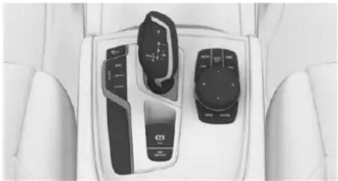
natural_image
Interior view of a car dashboard with two control switches and a touchscreen display (no visible text or symbols)
Rearview camera
Camera
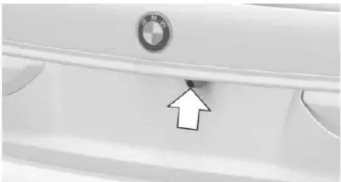
natural_image
Close-up of a white car door panel with a BMW logo and an arrow pointing to a small hole (no text or symbols visible)The camera lens is located in the handle of the tailgate.
The image quality may be impaired by dirt. Clean the camera lens, refer to page 294.
Switching on/off
Switching on automatically
With the engine running, engage lever in position P R.
Automatic deactivation during forward travel
The system switches off when a certain driving distance or speed is exceeded.
Switch the system back on if needed.
Switching on/off manually

Press button.
On: the LED lights up.
▶ Off: the LED goes out.
The PDC is shown on the Control Display.
The rearview camera image is displayed when the reverse gear is engaged by pressing the button.
Switching the view via iDrive
With PDC activated:
"Rear view camera"
The rearview camera image is displayed.
Display on the Control Display
Functional requirement
The rearview camera is switched on.
The trunk lid is fully closed.
Assistance functions
Activate/deactivate assistance functions
More than one assistance function can be active at the same time.
Parking aid lines"
Pathway lines and turning radius lines are displayed, refer to page 186.
Obstacle marking"
Spatially-shaped markings are displayed, refer to page 186.
Parking aid lines
Pathway lines
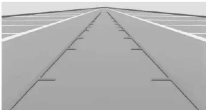
natural_image
Top-down view of a long, straight road with parallel tracks and lane markings (no text or symbols visible)Pathway lines help you to estimate the space required when parking and maneuvering on level roads.
Pathway lines depend on the current steering angle and are continuously adjusted to the steering wheel movements.
Turning circle lines
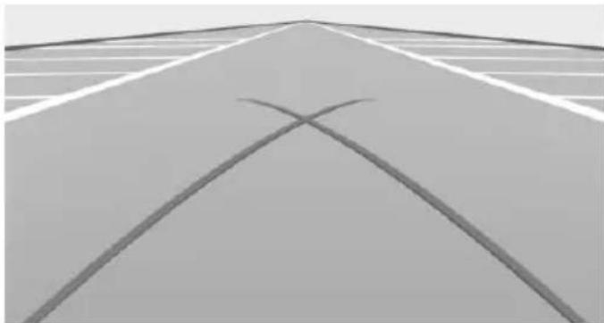
natural_image
Exterior view of a road with two curved lane markings (no text or symbols)Turning circle lines can only be superimposed on the rearview camera image together with pathway lines.
Turning circle lines show the course of the smallest possible turning radius on a level road.
Only one turning radius line is displayed after the steering wheel is turned past a certain angle.
Parking using pathway and turning radius lines
-
Position the vehicle so that the red turning radius line leads to within the limits of the parking space.
-
Turn the steering wheel to the point where the green pathway line covers the corresponding turning radius line.
Obstacle marking
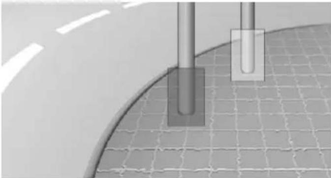
natural_image
Close-up of two vertical cylindrical components mounted on a curved surface with grid pattern below (no text or symbols visible)Obstacles behind the vehicle are detected by the PDC sensors.
Obstacle markings can be faded into the image of the rearview camera.
Their colored margins of the obstacle markings match the markings of the PDC.
Setting brightness and contrast via iDrive
With the rearview camera switched on:
-
Move the controller to the left.
-
▷ "Brightness"
Contrast"
- Set the desired value.
System limits
Deactivated camera
If the camera is deactivated, e.g. if the tailgate is open, the camera image is displayed hatched in gray.
Detection of objects
Very low obstacles as well as high, protruding objects such as ledges may not be detected by the system.
Assistance functions also take into account data of the PDC.
Follow instructions in the PDC chapter, refer to page 180.
The objects displayed on the Control Display under certain circumstances are closer than they appear. Do not estimate the distance from the objects on the display.
Malfunction
A camera malfunction is displayed on the Control Display.

A red symbol is displayed and the recording range of the malfunctioning camera is displayed in black on the
Control Display.
Surround View
The concept
The system provides assistance in parking and maneuvering. The area around the vehicle is shown on the Control Display.
Several cameras display the area from different selectable perspectives. In addition, assistance functions, e.g. guidelines, can be faded into the camera image.
General information
The following camera perspectives can be displayed:
▶ Automatic camera perspective: the system shows the camera perspective suitable for the respective driving situation, refer to page 188.
▶ Rearview camera: to represent the areas behind the vehicle, refer to page 188.
▶ Top view onto the vehicle, Top View, refer to page 188.
Right-hand and left-hand side view for representing the areas on the sides of the vehicle, refer to page 191.
▶ Camera perspective movable via iDrive, refer to page 188.
Panorama View: to present cross traffic, e.g. at junctions and driveways, depending on the currently engaged gear, refer to page 191.
Depending on the view, the environment around the vehicle or a part of it is depicted.
Information

WARNING
The system does not relieve from the personal responsibility to correctly assess the traffic situation. There is risk of an accident. Adjust the driving style to the traffic conditions. Watch traffic and vehicle surroundings closely and actively interfere in the respective situations.
Overview
Buttons in the vehicle
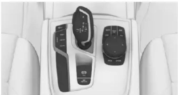
natural_image
Interior view of a car dashboard with two control switches and a digital display (no visible text or symbols)
Surround View

Panorama View
Cameras
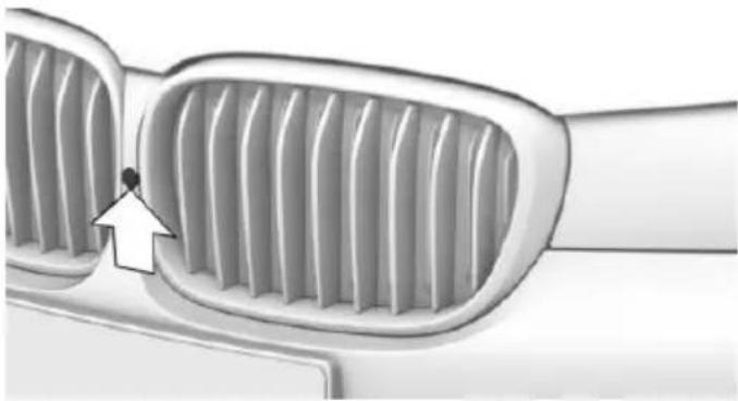
natural_image
Close-up of a car's front grille with a white arrow pointing to a specific grille (no text or symbols visible)Front camera
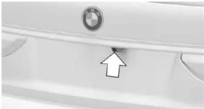
natural_image
Close-up of a white car door panel with a BMW logo and an arrow pointing to the bottom part (no text or symbols visible)Rearview camera
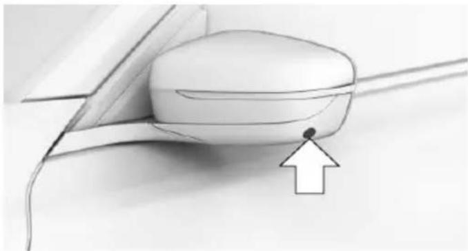
natural_image
Diagram of a computer mouse with an arrow pointing to the head area (no text or symbols present)There are two cameras at the bottom in the exterior mirror housings.
The image quality may be impaired by dirt on the camera lenses. Clean the camera lenses, refer to page 294.
Switching on/off
Switching on automatically
With the engine running, engage lever in position P R.
The camera perspective suitable for the respective driving situation is displayed.
Switching on/off manually

Press button.
On: the LED lights up.
▶ Off: the LED goes out.
The rearview camera cannot be switched off if the reverse gear is engaged.
Automatic deactivation during forward travel
The system switches off when a certain driving distance or speed is exceeded.
Switch the system back on if needed.
Display
Overview
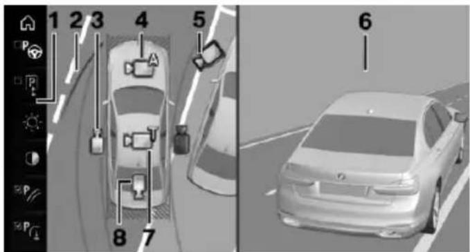
text_image
1 2 3 4 5 P P P A 8 7 61 Function bar
2 Selection window
3 Side view
4 Automatic camera perspective
5 Movable camera perspective
6 Camera image
7 Top View
8 Rearview camera
Selecting the camera perspective
General information
The individual camera perspectives can be selected in the selection window via iDrive.
Side view
The side view can be selected for the right or left vehicle side.
This view helps when positioning the vehicle at the curb or with other obstacles on the side by displaying the side surroundings.
The side view looks from rear to front and in case of danger, focuses automatically on possible obstacles.
Automatic camera perspective
The automatic camera perspective shows a steering-dependent view in the respective driving direction.
This perspective adapts to the respective driving situation.
As soon as obstacles are detected, the view changes to a fixed display of the area in front or at the rear behind the bumper or if necessary, changes to a side view.
Movable camera perspective
With selection of the movable camera perspective, a circle appears on the Control Display.
By turning the controller or via touch function, specified perspectives on the circle can be selected.
The current perspective is marked with a camera symbol.
With BMW Gesture Control: an additional camera symbols appears on the circuit. This camera symbol is freely movable via BMW Gesture Control, refer to page 30.
Exit the circle by pressing the controller or via touch function on the active camera symbol.
Top view
The top view shows the vehicle and surroundings from above.
Rearview camera
This view shows the picture of the rearview camera.
Function bar
Assistance functions can be activated, refer to page 189, via the function bar and settings applied.
▶ "Parking Assistant", refer to page 193.
▶ "Brightness", refer to page 192.
▶ "Contrast", refer to page 192.
▶ Parking aid lines", refer to page 190.
▶ "Obstacle marking", refer to page 190.
▶ "Car wash", refer to page 190.
▶ "Settings": apply settings, e.g. to use the activation points for Panorama View.
Assistance functions
Activate/deactivate assistance functions
More than one assistance function can be active at the same time.
The following assistance functions can be manually activated:
Parking aid lines"
▶ "Obstacle marking"
"Car wash"
The following assistance functions are automatically displayed:
▶ Side protection, refer to page 191.
▶ Rim protection, refer to page 191.
▶ Door opening angle, refer to page 191.
Parking aid lines
Pathway lines
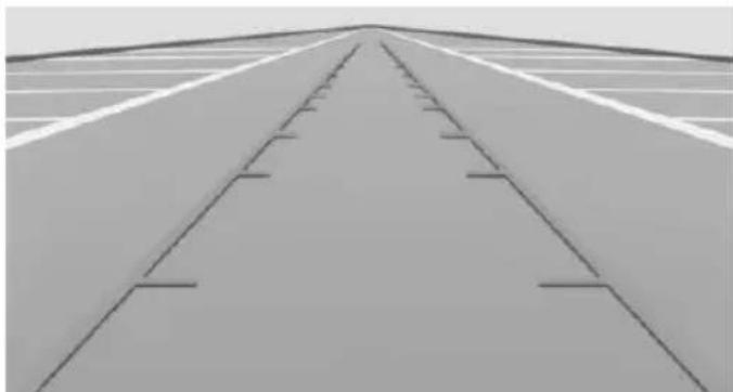
natural_image
Top-down view of a plain road with parallel tracks and lane markings (no text or symbols)Pathway lines help you to estimate the space required when parking and maneuvering on level roads.
Pathway lines depend on the current steering angle and are continuously adjusted to the steering wheel movements.
Turning circle lines
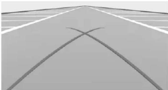
natural_image
Exterior view of a road with two intersecting curved lines forming an X shape (no text or symbols)Turning circle lines can only be superimposed on the rearview camera image together with pathway lines.
Turning circle lines show the course of the smallest possible turning radius on a level road.
Only one turning radius line is displayed after the steering wheel is turned past a certain angle.
Parking using pathway and turning radius lines
-
Position the vehicle so that the red turning radius line leads to within the limits of the parking space.
-
Turn the steering wheel to the point where the green pathway line covers the corresponding turning radius line.
Obstacle marking
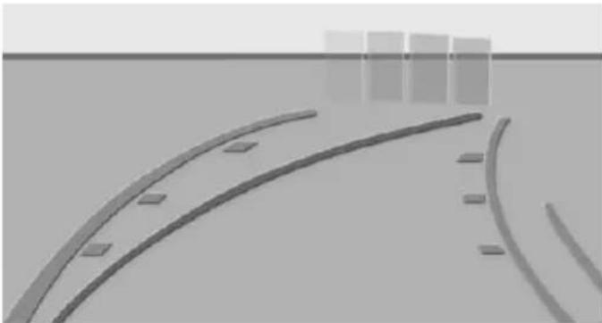
natural_image
Abstract grayscale illustration of curved road markings with rectangular blocks, no text or symbols presentObstacles behind the vehicle are detected by the PDC sensors.
Obstacle markings can be shown in the camera image.
Their colored margins of the obstacle markings match the markings of the PDC.
Car wash view
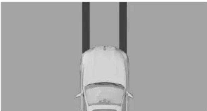
natural_image
Top-down view of a car with two vertical poles above the roof (no text or symbols visible)The car wash view assists when entering a car wash by displaying the floor and the own lane.
Side protection
The concept
Obstacles on the side of the vehicle are detected by the sensors of the system. The system warns against these obstacles.
Display
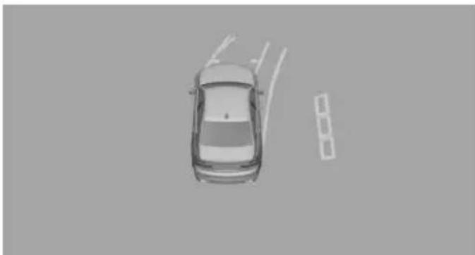
natural_image
Top-down view of a car on a road with a small inset image showing a vehicle (no text or symbols)Obstacle markings are displayed sideways on the vehicle to protect the vehicle sides.
▶ Gray markings: the area next to the vehicle was not captured.
▶ No markings: no obstacles were detected.
▶ Color markings: warning against detected obstacles.
Limits of side protection
The system only displays stationary obstacles that were previously detected by sensors while passing them.
The system does not detect, whether an obstacle moves later on. For this reason, at standstill, the markings are shown in the display in gray after a certain time. The area next to the vehicle must be newly captured.
Rim protection
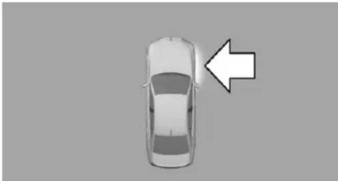
natural_image
Top-down view of a car with a white arrow pointing to the side (no text or symbols)An imminent collision of the wheel with the curb is displayed. The wheel in question is marked in red.
Door opening angle
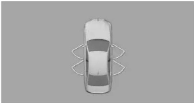
natural_image
Top-down view of a car with curved roof lines (no text or symbols)The maximum opening angle of the doors is displayed in selector lever position P.
Panorama View
The concept
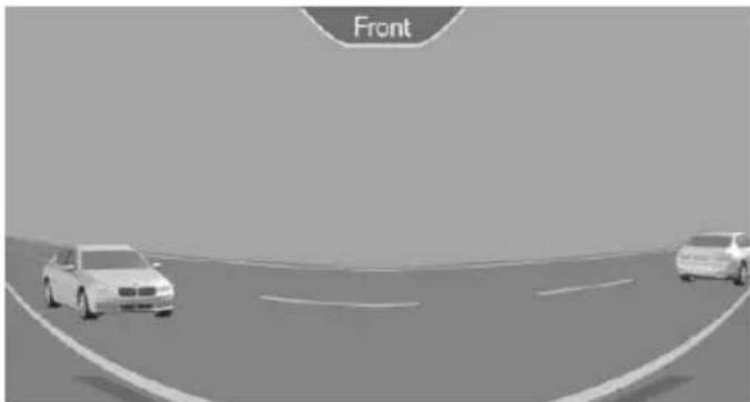
natural_image
Two cars driving on a curved road with lane markings, no visible text or symbolsThe system provides an early look at cross traffic at blind driveways and intersections. Road users concealed by obstacles to the left and right of the vehicle can only be detected
relatively late from the driver's seat. The cameras in the front and rear capture the sideways traffic area to improve the view.
Yellow lines in the screen display mark the front and rear end of the vehicle.
The camera image shows different levels of distortion in some areas and is thus not suitable for distance estimations.
Display on the Control Display

Press the button when the engine is running.
Depending on the driving direction, the image of the respective camera is displayed:
▶ "front": front camera image.
▶ "rear": rear camera image.
The cross traffic warning, refer to page 197, can additionally warn against oncoming vehicles using radar sensors.
With navigation system: activation points
The concept
Positions at which Panorama View is to switch on automatically can be stored as activation points as soon as a GPS signal is received.
Up to ten activation points can be stored.
Activation points can be used when driving forward for the front camera.
Storing activation points
- Drive to the position at which the system is to be switched on, and stop.
Press button.
- Move the controller to the left.
- "Add activation point"
The current position is displayed.
- "Add activation point"
Activation points are, if possible, stored with town/city and street address or with the GPS coordinates.
Using activation points
The use of activation points can be switched on and off.

Press button.
- Move the controller to the left.
- "Settings"
- "Panorama view, GPS-based"
- "Panorama view, GPS-based"
Displaying or deleting activation points

button.
- Move the controller to the left.
- "Show activation points"
A list of all activation points is displayed.
- "Delete this activation point" or "Delete all activation points"
Setting brightness and contrast via iDrive
With Surround View or Panorama View switched on:
- Move the controller to the left.
- ▷ "Brightness"
▶ "Contrast" - Set the desired value.
Functional limitations
The system can be used only to a limited extent in the following situations:
In poor light.
▶ In case of soiled cameras.
▶ With a door open.
▶ With the tailgate open.
▶ With exterior mirrors folded in.
Gray hatched areas with symbol, e.g. open door, in the camera image mark areas that are currently not displayed.
Gray hatched areas without symbol, e.g. in front of the vehicle, mark areas that are not visible to the cameras.
System limits
Non-visible areas
Areas around the vehicle that are not visible because of the viewing angle of the cameras, are presented hatched in gray.
Detection of objects
Very low obstacles as well as high, protruding objects such as ledges may not be detected by the system.
Assistance functions also take into account data of the PDC.
Follow instructions in the PDC chapter, refer to page 180.
The objects displayed on the Control Display under certain circumstances are closer than they appear. Do not estimate the distance from the objects on the display.
Malfunction
A camera malfunction is displayed on the Control Display.

A yellow symbol is displayed and the recording range of the malfunctioning camera is displayed in black on the
Control Display.
Parking assistant
The concept
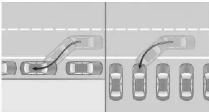
natural_image
Diagram showing two scenarios of driving a road with multiple cars, one moving rightward and the other on the right (no text or symbols)The system supports parking in the following situations:
When parking parallel to the road.
▷ When reverse parking diagonally to the road.
Ultrasound sensors measure parking spaces on both sides of the vehicle.
The system calculates the best possible parking line.
When parking parallel or diagonal to the road, the system takes control of steering, acceleration and braking and if needed changes the gears during the parking procedure.
Hold down the parking assistant button for the duration of the parking procedure. At the end of the parking procedure, the P selector lever position is set.
When parking, also take note of the visual and acoustic information and instructions issued by the PDC, the parking assistant and the rear-view camera and react accordingly.
A component of the system is the PDC Park Distance Control, refer to page 180.
Information
Loud noises from outside and inside the vehicle may prevent you from hearing the PDC's signal tone.

WARNING
The system does not relieve from the personal responsibility to correctly assess the traffic situation. Based on the limits of the system, it cannot independently react to all traffic situations. There is risk of an accident. Adjust the driving style to the traffic conditions. Watch traffic closely and actively interfere in the respective situations.

CAUTION
The parking assistant can steer the vehicle over or onto curbs. There is risk of property damage. Watch traffic closely and actively interfere in the respective situations.
An engine that has been switched off by the Auto Start Stop function is restarted automatically when the parking assistant is activated.
Overview
Button in the vehicle
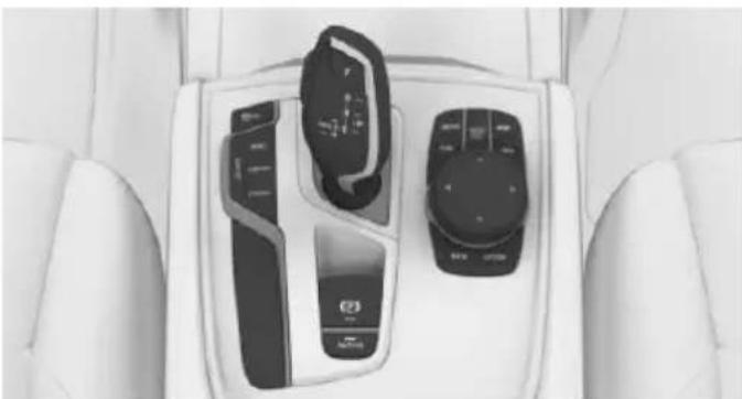
natural_image
Interior view of a car dashboard with control panels and buttons (no visible text or symbols)
Parking assistant
Ultrasound sensors
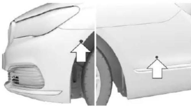
natural_image
Side view of a car showing the wheel rim and side profile with arrows indicating motion (no text or symbols)With the four side ultrasound sensors, arrows, and the ultrasound sensors of the PDC in the bumpers, the parking spaces are measured and the distances to obstacles determined.
To ensure full functionality:
Keep the sensors clean and free of ice, refer to page 294.
When using high-pressure washers, do not spray the sensors for long periods and maintain a distance of at least 12 in/30 cm.
Do not put stickers over sensors.
Requirements
For measuring parking spaces
▶ Maximum speed while driving forward approx. 22 mph/35 km/h.
▶ Maximum distance to row of parked vehicles: 5 ft/1.5 m.
Suitable parking space
General information:
▷ Gap behind an object that has a min. length of 1.7 ft/0.5 m.
▶ Gap between two objects with a minimum length of approx. 1.7 ft/0.5 m.
Parallel parking to the road:
Min. length of gap between two objects: your vehicle's length plus approx. 2.6 ft/0.8 m.
▶ Minimum depth: approx. 5 ft/1.5 m.
Diagonal parking:
▶ Width of gap between two objects: your vehicle's width plus approx. 2.3 ft/0.7 m up to maximum 16 ft/5 m.
▶ Minimum depth: your vehicle's length.
The depth of diagonal parking spaces must be estimated by the driver. Dur to technical limitations, the system can approximate the depth of diagonal parking spaces only.
Regarding the parking procedure
▶ Doors and trunk lid closed.
▶ Parking brake released.
▶ Driver's safety belt fastened.
Switching on/off
Switching on with the button

Press button.
The LED lights up.
The current status of the parking space search is indicated on the Control Display.

Parking assistant is activated automatically.
Switching on with reverse gear
Shift into reverse.
The current status of the parking space search is indicated on the Control Display.
To activate: "Parking Assistant"
Switch off
The system can be deactivated as follows:
▶ Press button.
Signal tone for switching suitable parking spaces on/off
About iDrive:
- "My Vehicle"
- "Vehicle settings"
-
"Parking"
-
"Parking Assistant"
- "Sound if parking space detected" Settings are stored.
Display on the Control Display
System activated/deactivated
Symbol Meaning

Gray: the system is not available.
White: the system is available but not activated.

The system is activated.
System status
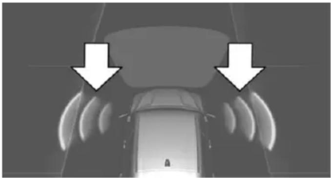
natural_image
Top-down view of a car with two white arrows pointing downward to the roof, indicating airflow or sound pressure (no text or symbols present)Colored symbols, arrows, on the side of the vehicle illustrated. Parking assistant is activated and search for parking space active.
▶ Control Display shows suitable parking spaces at the edge of the road next to the vehicle symbol. When the parking assistant is active, suitable parking spaces are highlighted in color and a signal tone sounds. Switch signal tone on/off, refer to page 195.
If a diagonal or parallel parking space is clearly detected, the system automatically adjusts the suitable parking method. In the case of parking spaces suitable for parallel and diagonal parking, a selection menu is displayed. In this case, the desired parking method must be selected manually.
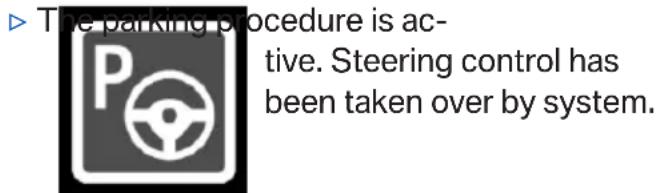
text_image
The parking procedure is ac- tive. Steering control has been taken over by system.Parking space search is always active whenever the vehicle is moving forward slow and straight, even if the system is deactivated. When the system is deactivated, the displays on the Control Display are shown in gray.
Parking using the parking assistant
-
Press the button or shift into reverse to switch on the parking assistant. Activate parking assistant if necessary.
P The parking assistant is activated. -
Drive by the row of parked vehicles at a speed of up to approx. 22 mph/35 km/h and at a distance of maximum 5 ft/1.5 m.
The status of the parking space search and possible parking spaces are displayed on the Control Display.
- Follow the instructions on the Control Display.
Hold down the parking assistant button for the duration of the parking procedure. At the end of the parking procedure, the P selector lever position is set.
The end of the parking procedure is indicated on the Control Display.
- Adjust the parking position yourself if needed.
Interrupting manually
The parking assistant can be interrupted at any time:
▶ "Parking Assistant" Select the symbol on the Control Display.
▶ Release button during the parking procedure.
Interrupting automatically
The system is interrupted automatically in the following situations:
▶ If the driver grasps the steering wheel or if he takes over steering.
▶ Possible on snow-covered or slippery road surfaces.
When there are obstacles that are hard to overcome, such as curbs.
▷ When there are obstacles that suddenly arise.
▶ If the Park Distance Control PDC displays clearances that are too small.
▶ If a maximum number of parking attempts or the time taken for parking is exceeded.
When switching to another function on the Control Display.
▶ When the button is released.
▶ If the tailgate is open.
▶ If doors are open.
▷ When setting the parking brake.
During acceleration.
When the brake pedal remains pressed for an extended period while the vehicle is stationary.
▶ When unfastening the driver's safety belt.
A Check Control message is displayed.
Resume
An interrupted parking procedure can be continued if needed.
Follow the instructions on the Control Display.
System limits
No parking assistance
The parking assistant does not offer assistance in the following situations:
In tight curves.
Functional limitations
The system may not be fully functional in the following situations:
On bumpy road surfaces such as gravel roads.
On slippery ground.
On steep uphill or downhill grades.
▶ With accumulations of leaves/snow in the parking space.
▶ With a mounted emergency wheel.
In case of changes to an already-measured parking space.
Limits of ultrasonic measurement
Ultrasonic measuring might not function under the following circumstances:
▶ For small children and animals.
▶ For persons with certain clothing, e.g. coats.
▶ With external interference of the ultrasound, e.g. from passing vehicles or loud machines.
▶ When sensors are dirty, iced over, damaged or out of position.
▶ Under certain weather conditions such as high relative humidity, rain, snowfall, extreme heat or strong wind.
▶ With tow bars and trailer couplings of other vehicles.
▶ With thin or wedge-shaped objects.
▶ With moving objects.
▶ With elevated, protruding objects such as ledges or cargo.
▶ With objects with corners and sharp edges.
▶ With objects with a fine surface structure such as fences.
▶ For objects with porous surfaces.
Low objects already displayed, e.g., curbs, can move into the blind area of the sensors before or after a continuous tone sounds.
Cargo that extends beyond the perimeter of the vehicle is not taken into account by the system.
It can happen that parking spaces are detected that are not suitable or suitable parking spaces are not detected.
Malfunction
A Check Control message is displayed.
The parking assistant failed. Have the system checked.
Cross traffic warning
The concept
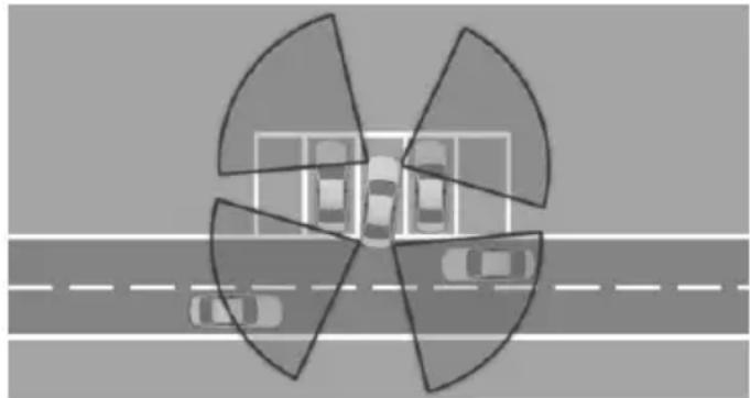
natural_image
Top-down view of a road with multiple cars parked around it, no visible text or symbolsTwo radar sensors in the rear bumper monitor the area behind the vehicle.
At blind driveways or when driving out of diagonal parking spaces, approaching cross traffic is earlier detected by the system than possible from the driver's seat.
The system indicates approaching traffic.
The lamp in the exterior mirror lights up, a signal tone may sound, and the respective indicator is called up on the Control Display.
With the respective equipment variant, the traffic area in front of the vehicle is monitored as well. Two additional radar sensors are located in the front bumpers.
Information

WARNING
The system does not relieve from the personal responsibility to correctly assess visibility and traffic situation. There is risk of an accident. Adjust the driving style to the traffic conditions. Watch traffic closely and actively interfere in the respective situations.
Overview
Button in the vehicle
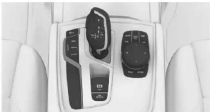
natural_image
Interior view of a car dashboard with three control switches and a touchscreen display (no visible text or symbols)
Parking assistance systems
Radar sensors
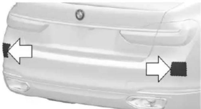
natural_image
Front view of a white car showing side bumper and side paint mark (no text or symbols)The radar sensors are located in the rear bumper.
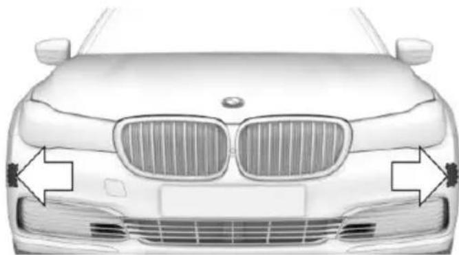
natural_image
Front view of a car with grille grilles and side profile arrows (no text or symbols)With the respective equipment variant, there are two additional radar sensors in the front bumper.
Always keep the bumper in the area of the radar sensors clean and unobstructed.
Switching on/off
Activating/deactivating the system

s button.
- Move the controller to the left.
- "Settings"
- "Cross traffic alert"
- "Crossing-traffic warning"
Switching on automatically
If the system is activated on the Control Display, it is automatically switched on as soon as PDC or Panorama View is active.
Switching off automatically
The system is automatically switched off in the following situations:
▷ When exceeding a speed of approx. 4 mph/7 km/h.
With the steering and lane guidance assistant active, when a certain driving distance is exceeded.
Display
Lamp in the exterior mirror
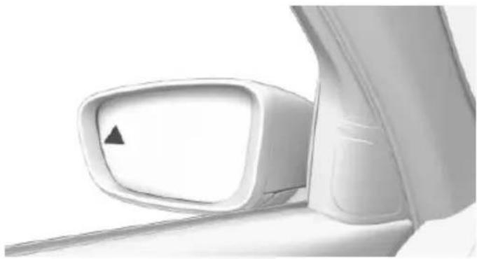
natural_image
Close-up of a car side mirror with a black triangular pointer on the left side (no text or symbols visible)The lamp in the exterior mirror flashes if vehicles are detected by the rear sensors and the vehicle is moving backwards.
Display in the PDC view
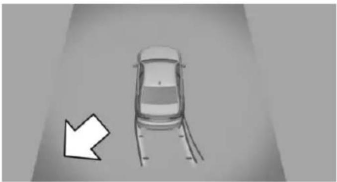
natural_image
Top-down view of a car with a white arrow pointing to it, no text or symbols presentThe respective boundary area in the PDC view flashes red, if vehicles are detected by the sensors.
Display in the camera view
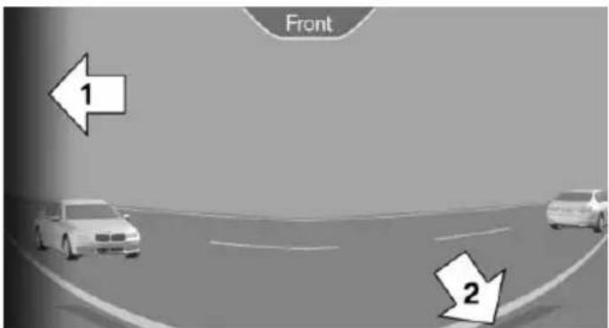
text_image
Front 1 2The respective boundary area, arrow 1, in the camera view flashes red, if vehicles are detected by the sensors.
Yellow lines, arrow 2, mark the front or rear edge of the own vehicle.
Acoustic warning
In addition to the optical indicator, a warning signal sounds if the own vehicle moves into the respective direction.
System limits
The system may not be fully functional in the following situations:
▶ If the speed of the approaching vehicle is very high.
In heavy fog, rain or snowfall.
In tight curves.
▶ If the bumper is dirty or iced up, or covered with stickers.
▶ If crossing objects move at a very slow speed.
If other objects are in the capture range of the sensors, that hide cross traffic.
Driving comfort
Vehicle features and options
This chapter describes all standard, country-specific and optional features offered with the series. It also describes features that are not necessarily available in your car, e.g., due to the selected options or country versions. This also applies to safety-related functions and systems. The respectively applicable country provisions must be observed when using the respective features and systems.
Air suspension
The concept
Air suspension ensures best possible driving comfort under all load conditions. Due to a variable adjustment of the front and rear axles, the damping is adjusted to the vehicle condition.
General information
In the case of an uneven road surface, the vehicle level can be elevated to increase ground clearance.
▶ Normal level, for normal road surface.
▶ Raised level, when the road surface is poor. In the SPORT driving mode, refer to page 110, or at higher speeds, the vehicle lowers itself.
Information

WARNING
With lowering the vehicle, body parts can be jammed. There is risk of injuries. When lowering the vehicle, make sure that the areas of movement under the vehicle and under the wheel housing are free.
Overview
Button in the vehicle
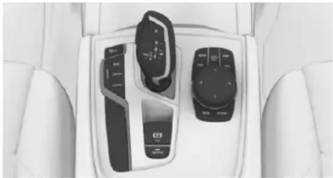
natural_image
Interior view of a car dashboard with two control switches and a touchscreen display (no visible text or symbols)
Level adjustment
Adjusting the level manually

Press button.
In the low speed range, the vehicle is raised to the raised level with a press of the button.
Starting at a speed of approx. 20 mph/35 km/h the vehicle lower itself automatically to the normal level.
Display
▶ LED off: normal level.
▶ LED flashes: level is being adjusted.
▶ LED lit: raised level.
▶ LED flashes fast: level adjustment not possible.
System limits
With several manual level changes one after another, the system will switch itself off if necessary. The fast-flashing LED on the button indicates that the system is temporarily unavailable.
Tire change
Before a tire change, deactivate the system:

Press button and hold for approx. 7 seconds, then release. The LED flashes fast.
Activate system:
The system is activated again automatically when you drive away.
Malfunction
A Check Control message is displayed. The system is disrupted. Vehicle handling may be altered and driving comfort may be noticeably reduced. Have checked by a dealer's service center or another qualified service center or repair shop.
Long periods when vehicle is parked
During long periods when the vehicle is parked, it can lower itself. This is not a malfunction.
Dynamic Damping Control
The concept
This system reduces undesirable vehicle motion when using a dynamic driving style or traveling on uneven road surfaces.
The system enhances driving dynamics and comfort fitting road surface and driving style.
General information
The system offers several different damping settings.
These are assigned to the different driving modes of the Driving Dynamics Control, refer to page 110.
Tuning
Drive mode Damper tuning
COMFORT PLUS comfortable
SPORT firm
COMFORT/ECO PRO balanced out
Executive Drive Pro
The concept
Executive Drive Pro is an actively controlled chassis. It increases driving comfort and minimizes the lateral tilt when driving around curves. This increases both the agility of the vehicle as well as the vehicle comfort.
Executive Drive Pro includes the following systems:
▶ Active damping adjustment, refer to page 201.
▶ Active roll stabilization, refer to page 202.
Active damping adjustment
The concept
The system increases driving comfort. Using a camera in the area of the interior mirror, the road surface is detected and damping automatically adjusted to the road surface.
Overview
Camera
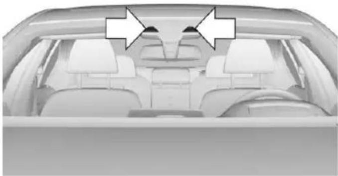
natural_image
Interior view of a car showing rear seats and driver seat, with two white arrows pointing to the dashboard (no text or symbols present)The camera is installed near the interior rear-view mirror.
Keep the windshield in the area behind the interior rearview mirror clean and clear.
General information
The system is active up to a speed of 75 mph/120 km/h.
System limits
Functional limitations
The system may not be fully functional or may not be available in the following situations:
In heavy fog, rain, sprayed water or snowfall.
In tight curves.
▶ At rapid steering angles.
When driving very close to the vehicle in front of you.
▶ Up to 10 seconds after the start of the engine, via the Start/Stop button.
During calibration of the camera immediately after vehicle delivery.
▶ If the field of view of the camera or the front windshield are dirty or covered.
▶ If there are constant blinding effects because of oncoming light, e. g., from the sun low in the sky.
When it is dark outside.
Malfunction
A Check Control message is displayed when there is a camera malfunction. Visit the nearest dealer's service center or another qualified service center or repair shop.
Active roll stabilization
The concept
The system reduces the lateral inclination of the vehicle that occurs during rapid driving in curves or during quick evasive maneuvers.
The lateral inclination of the vehicle is balanced out by permanent adjustment on the front and rear axles. The vehicle is thus always stabilized.
Agility and driving comfort are increased under all driving conditions.
General information
The system offers several different damping settings.
These are assigned to the different driving modes of the Driving Dynamics Control, refer to page 110.
Tuning
Drive mode Damper tuning
COMFORT/COMFORT comfortable PLUS
SPORT firm
Climate control
Vehicle features and options
This chapter describes all standard, country-specific and optional features offered with the series. It also describes features that are not necessarily available in your car, e.g., due to the selected options or country versions. This also applies to safety-related functions and systems. The respectively applicable country provisions must be observed when using the respective features and systems.
Automatic climate control
Overview
Switch in the center console
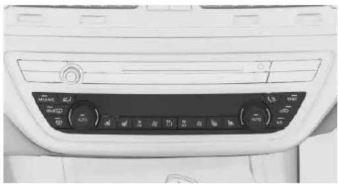
natural_image
Interior view of a car dashboard with control knobs and indicator lights (no visible text or symbols)Press but- function ton
Temperature, refer to page 204.
Climate control operation, refer to page 204.
Maximum cooling, refer to page 204.
AUTO program, refer to page 204.
| Press button | Function |
| Recirculated-air mode, refer to page 205. | |
| Air flow, manual, refer to page 205. | |
| Air distribution, manual, refer to page 205. | |
| SYNC | SYNC program, refer to page 206. |
| MAX | Defrost and defog window, refer to page 206. |
| Rear window defroster, refer to page 206. | |
| Active seat ventilation, refer to page 92. | |
| Seat heating, refer to page 91. | |
| Ambient air package, refer to page 211. |
Climate control functions in detail
Switching the system on/off
Switching on
Press any button except:
▶ Rear window defroster.
▶ Left side of Air volume button.
▶ Seat heating.
▶ Seat ventilation.
▷ SYNC program.
Switch off
▶ Complete system:
Press and hold the left button on the driver's side until the control clicks off.
On the front passenger side:
Press and hold the left button on the front passenger side.
Temperature
Turn the ring to set the desired temperature.
The automatic climate control achieves this temperature as quickly as possible, if needed by using the maximum cooling or heating capacity, and then keeps it constant.
Do not rapidly switch between different temperature settings. Otherwise, the automatic climate control will not have sufficient time to adjust the set temperature.
Information
Symbol is displayed permanently on the display of the automatic climate control.
Cooling function
The car's interior can only be cooled with the engine running.
Press button. The LED lights up.
The air will be cooled and dehumidi-
fied and, depending on the temperature setting, warmed again.
Depending on the weather, the windshield and side windows may fog up briefly when the engine is started.
The cooling function is switched on automatically with the AUTO program.
When using the automatic climate control, condensation water, refer to page 236, develops that exits underneath the vehicle.
Maximum cooling
Press button.
The system is set to the lowest temperature, optimum air flow and air circulation mode.
Air flows out of the vents to the upper body region. The vents need to be open for this.
The function is available with external temperatures beyond approx. 32 °F/0 °C and with the engine running.
Adjust air flow on the driver's side with the program active.
AUTO program
Press button.
Air flow, air distribution and temperature are controlled automatically.
Depending on the selected temperature, AUTO intensity program and outside influences, the air is directed to the windshield, side windows, upper body, and into the footwell.
The cooling function, refer to page 204, is switched on automatically with the AUTO program.
At the same time, a condensation sensor controls the program so as to prevent window condensation as much as possible.
To switch off the program: press the button again or manually adjust the air distribution.
Intensity of the AUTO program
With the AUTO program activated, the automatic intensity control can be changed.

Press the left or right side of the button: decrease or increase the intensity.
The selected intensity is shown on the display of the automatic climate control.
Automatic recirculated-air control AUC
The concept
The automatic recirculated air control AUC automatically recognizes odors or pollutants in the outside air. The outside air supply is then automatically shut off, the interior air is recirculated.
General information
If the system is activated, a sensor detects pollutants in the outside air and controls the shut-off automatically.
If the system is deactivated, outside air continuously flows into the car's interior.
With constant recirculated-air mode, the air quality in the car's interior deteriorates and the fogging of the windows increases.
If there is window condensation, switch off the recirculated-air mode
and press the button on the driver's side to utilize the condensation sensor. Make sure that air can flow to the windshield.
Switching on/off
About iDrive:
- "My Vehicle"
- "Vehicle settings"
- "Climate functions"
- "Air quality"
- "Automatic air recirculation"
Recirculated-air mode
The concept
You may respond to unpleasant odors or pollutants in the immediate environment by temporarily suspending the supply of outside air. The system then recirculates the air currently within the vehicle.
Operating via button
Press button repeatedly to select an operating mode:
▶ LED off: outside air flows in continuously.
▶ LED on: the supply of outside air is permanently shut off.
With constant recirculated-air mode, the air quality in the car's interior deteriorates and the fogging of the windows increases.
If there is window condensation, switch off the recirculated-air mode
and press the button on the driver's side to utilize the condensation sensor. Make sure that air can flow to the windshield.
Air flow, manual
To manually adjust air flow turn off AUTO program first.
Press the left or right side of the button: decrease or increase air flow.
The selected air flow is shown on the display of the automatic climate control.
The air flow of the automatic climate control may be reduced automatically to save battery power.
Manual air distribution
Press button repeatedly to select a program:
▶ Windows, upper body region, and footwell.
▶ Upper body region and footwell.
▶ Footwell.
▶ Windows and footwell.
▷ Windows.
▶ Windows and upper body.
▶ Upper body region.
The selected air distribution is shown on the display of the automatic climate control.
If there is window condensation, press the button on the driver's side to uti-condensation sensor.
SYNC program
Press button.
The current settings on the driver's side for temperature, air flow, air distribution, and AUTO program are transferred to the front passenger side and to the left and right rear.
To switch off, press the button again.
The program is switched off if the settings on the front passenger side or in the rear are changed.
Defrosts windows and removes condensation
Press button.
Ice and condensation are quickly removed from the windshield and the front side windows.
For this purpose, point the side vents onto the side windows as needed.
Adjust air flow with the program active.
If there is window condensation, you can also switch on the air conditioning or press the button to utilize the condensation sensor.
Rear window defroster
Press button.
The rear window defroster switches off automatically after a certain period of time.
Microfilter/activated-charcoal filter
The microfilter removes dust and pollen from the incoming air.
The activated-charcoal filter removes gaseous pollutants from the outside air that enters the vehicle.
This combined filter should be replaced during scheduled maintenance, refer to page 279, of your vehicle.
Ventilation
Setting
The air flow directions can be individually adjusted:
▶ Direct ventilation:
The air flow is directly pointed onto the person. The air flow heats or cools noticeably, depending on the adjusted temperature.
Indirect ventilation:
If the vents are fully or partly closed, the air is directly routed into the car's interior.
Indirect ventilation can also be adjusted on the Control Display.
Front ventilation
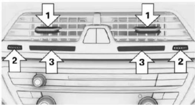
text_image
1 2 3 1 3 2▶ Lever for changing the air flow direction, arrow 1.
▶ Thumbwheel for continuous opening and closing of the vents, arrow 2
▶ Touch sensor or thumbwheel to vary the temperature, arrow 3.
With touch sensor, push the marking in the desired direction:
Toward blue: colder.
Toward red: warmer.
The set interior temperature for the driver and passenger are not changed.
Adjusting the ventilation
▶ Ventilation for cooling:
Direct vent in your direction when vehicle's interior is too hot.
Draft-free ventilation:
Adjust the vent to let the air flow past the occupants.
Indirect ventilation
Air is indirectly routed into the car's interior.
About iDrive:
- "My Vehicle"
- "Vehicle settings"
- "Climate functions"
- "Indirect ventilation"
Ventilation in rear, center
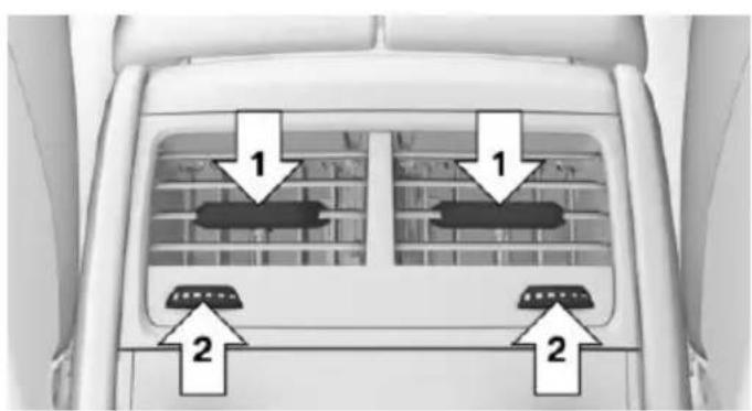
text_image
1 1 2 2 2▶ Lever for changing the air flow direction, arrow 1.
▶ Thumbwheels to vary the temperature, arrow 2.
Toward blue: colder.
Toward red: warmer.
Lateral ventilation
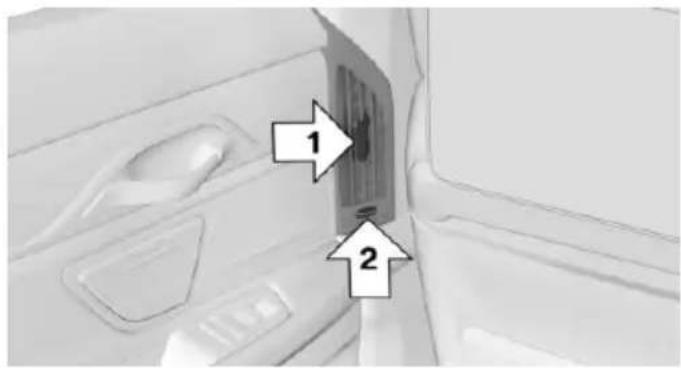
text_image
Diagram showing a vehicle interior with labeled parts, including numbered annotations 1 and 2 pointing to specific areas.▶ Lever for changing the air flow direction, arrow 1.
▶ Thumbwheel for continuous opening and closing of the vents, arrow 2.
Rear automatic climate control
Overview
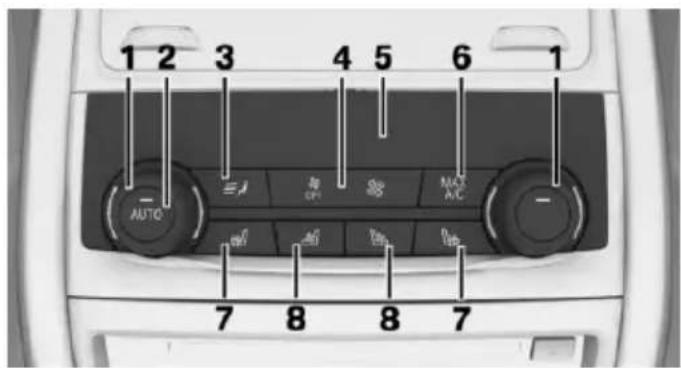
text_image
1 2 3 4 5 6 1 AUTO 7 8 8 71 Temperature
2 AUTO program
3 Air distribution, manual
4 Air flow, AUTO intensity
5 Display
6 Maximum cooling
7 Seat heating 91
8 Active seat ventilation 92
Switch on/off: via iDrive
- "My Vehicle"
- "Vehicle settings"
- "Climate functions"
- "Rear climate"
The rear automatic climate control is not ready for operation if the automatic climate control is switched off or if the function for defrosting or defogging the windows is active: defrost windows and remove condensation.
Switch on/off: via button
Switching on
Press any button except:
▶ Left side of Air volume button.
▶ Seat heating.
▶ Seat ventilation.
Switch off
Press and hold the left button.
AUTO program
Press button.
Air flow, air distribution, and tempera-
ture are controlled automatically:
Depending on the selected temperature, the AUTO intensity, and outside influences, the air is directed to the upper body and into the footwell.
The cooling function is switched on automatically with the AUTO program.
Intensity of the AUTO program
With the AUTO program activated, the automatic intensity control can be changed:
Press the left or right side of the button: decrease or increase the inten-
sity.
The selected intensity is shown on the display of the automatic climate control.
Temperature
Turn the ring to set the desired temperature.
The automatic climate control achieves this temperature as quickly as possible, if needed by using the maximum cooling or heating capacity, and then keeps it constant.
Do not rapidly switch between different temperature settings. The automatic climate control will not have sufficient time to adjust the set temperature.
The temperature can also be operated using BMW Touch Command.
Information
??? Symbol is displayed permanently on the display of the automatic climate control.
Manual air distribution
The air distribution can be adjusted to individual needs.
Press button repeatedly to select a program:
▶ Upper body region.
▶ Upper body region and footwell.
▶ Footwell.
The air distribution can also be operated using BMW Touch Command.
Air flow, manual
To manually adjust air flow turn off AUTO program first.
Press the left or right side of the button: decrease or increase air flow.
The selected air flow is shown on the display of the automatic climate control.
The air flow can also be operated using BMW Touch Command.
Maximum cooling
Press button.
The system is set to the lowest temperature, maximum air flow and air circulation mode.
Air flows out of the vents to the upper body region. The vents need to be open for this.
Air is cooled as quickly as possible:
At an external temperature of approx. 32 °F/0 °C.
When the engine is running.
Operation is also possible using BMW Touch Command.
Climate control operation on the roofliner
Temperature
Turn the ring to set the desired temperature.
Air flow
Press the left or right side of the button: decrease or increase air flow.
LEDs indicate the intensity of the air supply.
The air flow may be reduced automatically to save battery power.
Ventilation
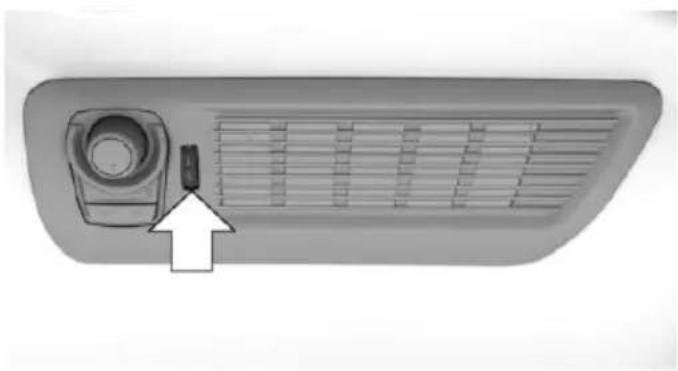
natural_image
Top-down view of a vehicle air vent with a mounted sensor and ventilation grille (no text or symbols visible)Thumbwheel for changing the air flow direction.
Parked-car ventilation/heating
The concept
The parked-car ventilation ventilates the vehicle interior and lowers its temperature, if needed.
The parked-car heating warms the vehicle interior, making snow and ice easier to remove.
The system uses the fuel of the vehicle for heat generation.
Parked-car ventilation and parked-car heating can be switched on and off directly or via a pre-set departure time.
The reel-on time is automatically determined based on the external temperature. The system promptly switches on before the selected departure time.
Information

DANGER
If the exhaust pipe is blocked or ventilation is insufficient, harmful exhaust gases can enter into the vehicle. The exhaust gases contain carbon monoxide, an odorless and colorless but highly toxic gas. In enclosed areas, exhaust gases can also accumulate outside of the vehicle. There is danger to life. Keep the exhaust pipe free and ensure sufficient ventila-
tion. Do not switch on parked-car heating in enclosed areas.

WARNING
During parked-car heating operation, high temperatures can occur underneath the body, e.g. caused by the exhaust gas system. If combustible materials, such as leaves or grass, come in contact with hot parts of the exhaust gas system, these materials can ignite. There is risk of fire. Make sure that no combustible materials can come in contact with hot vehicle parts during parked-car heating operation.
At external temperatures below 32 ^/0 ^ , water vapor occurs that emerges from below the vehicle.
Functional requirements
The vehicle is in the idle or operating readiness state.
▶ Battery is sufficiently charged.
▶ Parked-car heating: the fuel tank is filled to above the reserve range.
Open the vents to allow air to flow out.
Switching on/off directly
There are different ways to switch the system on or off.
It switches of automatically after some time.
The system continues to run for some time after being switched off.
Via the automatic climate control button
When the vehicle is in standby state, parked-car ventilation can be switched on or off via the automatic climate control buttons.
Press any button except:
▶ Rear window defroster.
▶ Left side of Air volume button.
▶ Seat heating.
▶ Seat ventilation.
▷ SYNC program.
Via the iDrive
Parked-car ventilation can be switched on or off via iDrive.
- "My Vehicle"
- "Vehicle settings"
- "Climate functions"
- "Comfort ventilation" or "Comfort heating/ventilation"
- "Activate now"
✿ symbol on the automatic climate control signals to switched on system.
Via BMW display key
Parked-car ventilation and parked-car heating can be switched on or off via the BMW display key.
Switching on directly
- Switch on the display of the BMW display key.
- "Climate control setting"
- Tap symbol.
- "Activate now"
- "Start"
Switching off directly
- Switch on the display of the BMW display key.
- "Climate control setting"
- Tap symbol.
- "Stop"
Departure time
Different departure times can be adjusted to ensure a comfortable interior temperature in the vehicle at the time of departure.
▶ One-time departure time: the time can be set.
The system is switched on once at the desired time.
Departure time with weekday: time and day of the week can be set.
The system is switched on repeatedly on the desired day of the week and time.
The departure time is pres-set in two steps:
▷ Set departure times.
▶ Activate departure times.
Setting departure time
Via the iDrive
- "My Vehicle"
- "Climate functions"
- "Comfort ventilation" or "Comfort heating/ventilation"
- Select the desired departure time.
- Set the departure time.
- Select day of the week if needed.
Via BMW display key
- Switch on the display of the BMW display key.
- "Climate control setting"
- Tap symbol.
- Select the desired departure time.
- If necessary, tap day of the week.
- Select time.
- "OK"
Activating the departure time
If a departure time should influence the switching on of parked-car heating/ventilation, the respective departure time must be activated first.
Via the iDrive
- "My Vehicle"
-
"Climate functions"
-
"Comfort heating/ventilation"
- "For departure time"
Activate the desired departure time.
The symbol on the automatic climate control signals an activated departure time.
Via BMW display key
- Switch on the display of the BMW display key.
- "Climate control setting"
- Tap symbol.
- Tap symbol.
Activate the desired departure time.
Ambient air package
The concept
The Ambient Air Package can be used to clean and scent the interior air with high-quality fragrances.
Two fragrances can be selected in the vehicle. A variety other fragrances is possible by replacing the fragrance cartridges.
Ionization is used to clean the air from suspended particles. Together with the selected fragrance, ionization enhances well-being and relaxation while driving.
Ionization
Ionization cleans the vehicle's interior air of suspended particles.
Switching ionization on/off
About iDrive:
- "My Vehicle"
- "Vehicle settings"
- "Climate functions"
- "Air quality"
- "Ionization"
An indicator in the climate control display signals that the ionization is switched on.
Ionization can also be operated using BMW Touch Command.
Fragrancing
General information
Perfuming is done at intervals in order to avoid a habituation effect.
Two fragrance cartridges in the vehicle allow comfortable switching between the fragrances.
The fragrance cartridges are located in the glove compartment.
Overview
Button in the center console
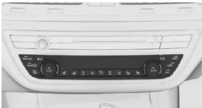
natural_image
Interior view of a car dashboard with control buttons and ventilation grilles (no visible text or symbols)
Switch fragrancing on/off, adjust intensity.
Functional requirements
▶ Fragrance cartridges are sufficiently filled.
▶ Interior temperature between 41 °F/+5 °C and 104 °F/+40 °C.
Selecting the fragrance
Two different fragrances can be selected in the vehicle.
About iDrive:
- "My Vehicle"
-
"Vehicle settings"
-
"Climate functions"
- "Air quality"
- "Fragrance"
- Select desired setting.
The setting is stored for the drive profile currently used.
Switching fragrancing on/off, adjusting intensity
The fragrance intensity can be adjusted on the Control Display or via the button on the center console.
Adjusting via iDrive
- "My Vehicle"
- "Vehicle settings"
- "Climate functions"
- "Air quality"
- "Fragrance"
- "Level"
- Select desired setting.
Adjusting via button
Press button once for each intensity level.
Highest intensity if three bars are shown on the climate control display.
Fragrancing is deactivated if no bars are displayed.
Adjusting via BMW Touch Command
The ambient air package can also be operated using BMW Touch Command.
Display
On the Control Display
With operation via button, the menu of the Ambient Air Package can be displayed on the Control Display automatically.
Thus additional settings can be made if desired.
About iDrive:
- "My Vehicle"
- "Vehicle settings"
- "Climate functions"
- "Air quality"
- "Fragrance"
- "Show fragrance setting"
The menu is shown on the Control Display.
Fragrance cartridge filling level
The illustrations on the Control Display show the actual filling level of the fragrance cartridges.
About iDrive:
- "My Vehicle"
- "Vehicle settings"
- "Climate functions"
- "Air quality"
- "Fragrance"
The fill level of the current fragrance is displayed.
- Select desired setting.
If an empty fragrance cartridge is indicated, carrier fluid is still left. However, it is not sufficient for the perfuming.
A required fragrance cartridge replacement is automatically indicated on the Control Display.
Inserting fragrance cartridges
The system can be accessed via the glove compartment.
- Open the glove compartment, refer to page 225.
- Press on the bottom of the cartridge holder, arrow.
The cartridge holder slides down.
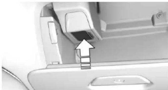
natural_image
Close-up of a printer's front panel showing a printer slot and a paper clip, with an arrow pointing to the slot (no text or symbols visible)- Remove cover of the fragrance cartridge to be inserted. Touch the cover on its top to push it away from the fragrance cartridge, arrow 1.
Insert the cover on the back side of the fragrance cartridge, arrow 2.
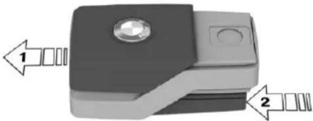
natural_image
3D diagram of a mechanical component with two directional arrows labeled 1 and 2 pointing to features (no text or symbols on the object itself)- Position fragrance cartridge such that the chip faces away from the cartridge holder, arrow 1.
Insert the fragrance cartridge without pressure into the cartridge holder, arrow 2. The cartridge engages easily noticeable.
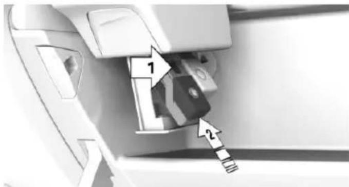
text_image
Diagram of a device interior showing labeled parts with arrows indicating direction or flow- Push the cartridge holder up, until it engages.
Make sure that no objects press against the cartridge holder from below, otherwise the function of the ambient air package could be impacted.
- Close the glove compartment.
Removing the fragrance cartridge
The fragrance cartridges are accessed via the glove compartment.
-
Open the glove compartment, refer to page 225.
-
Press on the bottom of the cartridge holder, arrow.
The cartridge holder slides down.
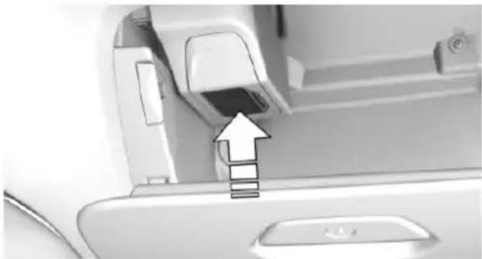
natural_image
Close-up of a printer's front panel showing a printer slot and a paper clip, with an arrow pointing to the slot (no text or symbols visible)- Fragrance cartridge, arrow 1: corresponds to the first fragrance indicated on the Control Display.
Fragrance cartridge, arrow 2: corresponds to the second fragrance indicated on the Control Display.

natural_image
Close-up of a car interior showing a door handle and internal components (no visible text or symbols)- Pull the desired fragrance cartridge from the holder, arrow.
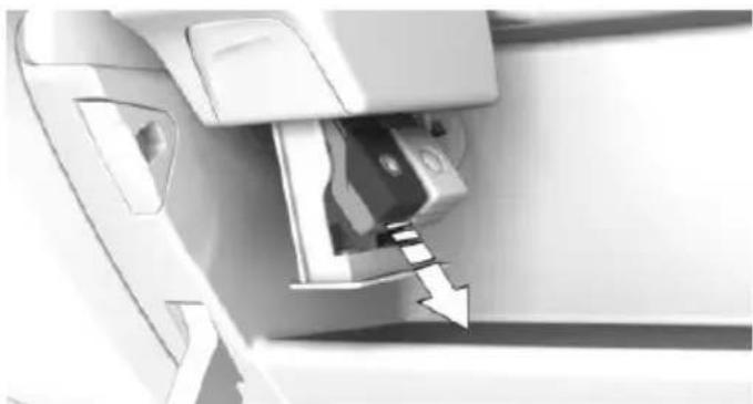
natural_image
Close-up of a mechanical component with an arrow indicating a specific part (no visible text or symbols)Empty fragrance cartridges can taken to a dealer's service center or another qualified service center or repair shop for recycling.
If the fragrance cartridges are refilled with fragrance of a different brand, the vehicle manufacturer will not assume warranty for possible effects of the fragrances on interior materials, e.g. odor, deposits, color changes, or possible system damages.
Interior equipment
Vehicle features and options
This chapter describes all standard, country-specific and optional features offered with the series. It also describes features that are not necessarily available in your car, e.g., due to the selected options or country versions. This also applies to safety-related functions and systems. The respectively applicable country provisions must be observed when using the respective features and systems.
Universal Integrated Remote Control
The concept
The universal garage door opener can operate up to 3 functions of remote-controlled systems such as garage door drives or lighting systems. The universal garage door opener replaces up to 3 different hand-held transmitters. To operate the remote control, the buttons on the interior rearview mirror must be programmed with the desired functions. The hand-held transmitter for the particular system is required in order to program the remote control.
Before selling the vehicle, delete the stored functions for the sake of security.
Information

WARNING
Body parts can be jammed when operating remote-controlled systems, e.g. the garage door, using the universal garage door opener. There is risk of injuries or risk of property damage. Make sure that the area of movement of the respective system is clear during programming and operation. Also follow the safety instructions of the hand-held transmitter.
Compatibility

If this symbol is printed on the packaging or in the instructions of the system to be controlled, the system is generally compatible with the universal garage door opener.
If you have any questions, please contact:
A dealer's service center or another qualified service center or repair shop.
▶ www.homelink.com on the Internet.
HomeLink is a registered trademark of Gentex Corporation.
Controls on the interior rearview mirror
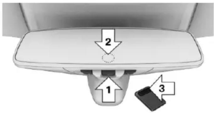
text_image
2 1 3▶ Buttons, arrow 1
▷ LED, arrow 2.
The hand-held transmitter, arrow 3, is required for programming.
Programming
General information
- Turn on operations.
- Initial setup:
Press and hold the left and right buttons on the interior mirror simultaneously for approximately 10 seconds until the LED flashes rapidly green. This erases all pro-
gramming of the buttons on the interior rearview mirror.
-
Press the interior mirror button to be programmed. The LED flashes orange.
-
Hold the hand-held transmitter for the system to be controlled approx. 1 to 3 in/2.5 to 8 cm away from the buttons of the interior mirror. The required distance depends on the manual transmitter.
-
Press and hold the button of the desired function on the hand-held transmitter. The LED on the interior mirror will begin flashing slowly orange.
-
As soon as the LED flashes green more rapidly or lights up continuously, release the button. Green light indicates that the button on the interior mirror was programmed. Faster green flashing indicates that it is a change-code wireless system.
If the LED does not flash faster after at least 60 seconds, change the distance between the interior rearview mirror and the hand-held transmitter and repeat the step. Several more attempts at different distances may be necessary. Wait at least 15 seconds between attempts.
Canada: if programming with the hand-held transmitter was interrupted, hold down the interior rearview mirror button and repeatedly press and release the hand-held transmitter button for 2 seconds.
- To program other functions on other buttons, repeat steps 3 to 5.
The systems can be controlled using the interior rearview mirror buttons.
Special feature of the alternating-code wireless system
If you are unable to operate the system after repeated programming, please check if the system to be controlled features an alternating-code system.
Read the system's operating manual, or press the programmed button on the interior rearview mirror longer. If the LED on the interior rearview mirror starts flashing rapidly and then stays lit constantly for 2 seconds, the system features an alternating-code system. Flashing and continuous illumination of the LED will repeat for approximately 20 seconds.
For systems with an alternating-code system, the universal garage door opener and the system also have to be synchronized.
Please read the operating manual to find out how to synchronize the system.
Synchronizing is easier with the aid of a second person.
To synchronize:
- Park the vehicle within range of the remote-controlled system.
- Program the relevant button on the interior rearview mirror as described.
- Locate and press the synchronizing button on the system being programmed. You have approx. 30 seconds for the next step.
- Hold down the programmed button on the interior rearview mirror for approximately 3 seconds and then release it. If necessary, repeat this step up to three times in order to finish synchronization. Once synchronization is complete, the programmed function will be carried out.
Reprogramming individual buttons
- Turn on operations.
- Press the interior mirror button to be programmed.
-
As soon as the interior mirror LED starts flashing slowly, hold the hand-held transmitter for the system to be controlled approx. 1 to 3 in/2.5 to 8 cm away from the buttons of the interior mirror. The required distance depends on the manual transmitter.
-
Likewise, press and hold the button of the desired function on the hand-held transmitter.
- Release both buttons as soon as the interior mirror LED flashes more rapidly or lights up continuously. The LED flashing more rapidly or being continuously light up indicates that the button on the interior mirror has been programmed. The system can then be controlled by the button on the interior rearview mirror.
If the LED does not flash faster after at least 60 seconds, change the distance and repeat the step. Several more attempts at different distances may be necessary. Wait at least 15 seconds between attempts.
Canada: if programming with the hand-held transmitter was interrupted, hold down the interior rearview mirror button and repeatedly press and release the hand-held transmitter button for 2 seconds.
Controls

WARNING
Body parts can be jammed when operating remote-controlled systems, e.g. the garage door, using the universal garage door opener. There is risk of injuries or risk of property damage. Make sure that the area of movement of the respective system is clear during programming and operation. Also follow the safety instructions of the hand-held transmitter.
The system, such as the garage door, can be operated using the button on the interior mirror while the drive or operating readiness is switched on. To do this, hold down the button within receiving range of the system until the function is activated. The interior rearview mirror LED stays lit while the wireless signal is being transmitted.
Deleting stored functions
Press and hold the left and right button on the interior mirror simultaneously for approximately 10 seconds until the LED flashes rapidly green. All stored functions are deleted. The functions cannot be deleted individually.
Sun visor
Glare shield
Fold the sun visor down or up.
Glare shield from the side
Folding out
- Fold the sun visor down.
- Unhook it from the holder and swing it to the side.
- Move it back to the desired position.
Folding up
Proceed in the reverse order to close the sun visor.
Vanity mirror
A vanity mirror is located in the sun visor behind a cover. When the cover is opened, the mirror lighting switches on.
Ashtray
Front
Opening
- Push the cover forward until it engages behind the cup holders. Push the cover for-
ward again until it engages behind the storage compartment.
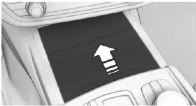
natural_image
Illustration of a car interior with a large upward arrow and a striped pattern on the screen (no text or symbols)- Fold the cover upward.
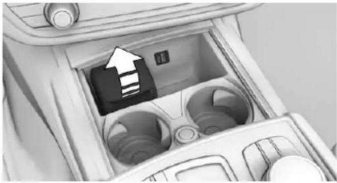
natural_image
Interior view of a car air conditioner unit with a highlighted internal component (no text or symbols visible)Emptying
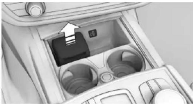
natural_image
Interior view of a car airway with a directional arrow pointing to the main component (no text or symbols visible)Grasp the insert on the side and pull it out.
Rear
Opening
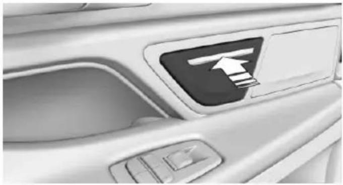
natural_image
Close-up of a car's front panel showing a directional arrow icon (no text or symbols)Press on the cover, arrow.
Emptying

natural_image
Interior view of a car showing a black plastic waste bin with arrows indicating flow or placement (no text or symbols visible)Grasp the insert on the side, arrows, and remove it.
Lighter
Information

WARNING
Contact with hot heating elements or the hot socket of the cigarette lighter can cause burns. Flammable materials can ignite if the cigarette lighter falls down or is held against the respective objects. There is risk of fire and injuries. Hold the cigarette lighter on its handle. Make sure that children do not use the cigarette lighter and do not burn themselves, e.g. by carrying the remote control along when exiting the vehicle.

CAUTION
If metal objects fall into the socket, they can cause a short circuit. There is risk of property damage. Replace the cigarette lighter or socket cover again after using the socket.
Front center console
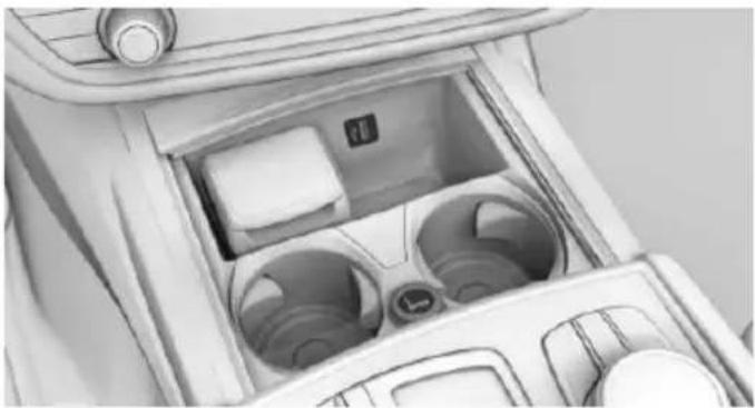
natural_image
Interior view of a car airway with visible compartments and control panel (no text or symbols)The cigarette lighter is located between the cup holders.
Rear center console
Without rear console
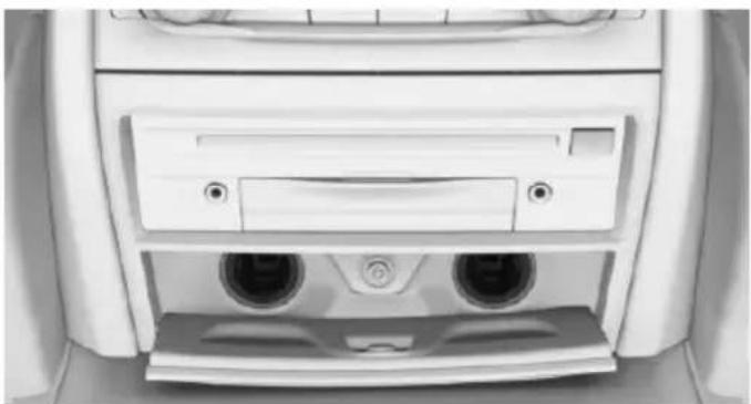
natural_image
Top-down view of a car air vent with two circular buttons and a door (no text or symbols visible)Open the cover. The cigarette lighter is on the right side.
To close the cover, tap it again.
With rear console
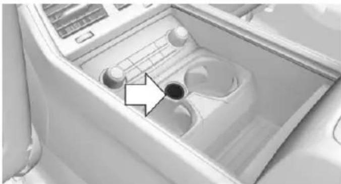
natural_image
Interior view of a car gear shift lever with control panel and mode dial (no text or symbols visible)Slide the cover rearward. The cigarette lighter is located between the cup holders.
Controls
Push in the lighter.
The lighter can be removed as soon as it pops back out.
Connecting electrical devices
Information

CAUTION
Battery chargers for the vehicle battery can work with high voltages and currents, which means that the 12V on-board network can be overloaded or damaged. There is risk of property damage. Only connect battery chargers for the vehicle battery to the starting aid terminals in the engine compartment.

CAUTION
If metal objects fall into the socket, they can cause a short circuit. There is risk of property damage. Replace the cigarette lighter or socket cover again after using the socket.
Sockets
General information
The lighter socket can be used as a socket for electrical equipment when operation and the drive-ready state are switched on.
Information
The total load of all sockets must not exceed 140 watts at 12 volts.
Do not damage the socket by using non-compatible connectors.
Front center console
- Push the cover forward until it engages behind the cup holders.
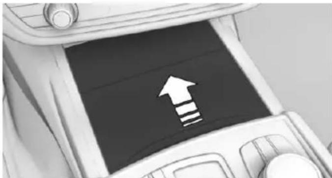
natural_image
Interior view of a car dashboard with an upward arrow icon (no text or symbols)- Remove the cover or cigarette lighter.
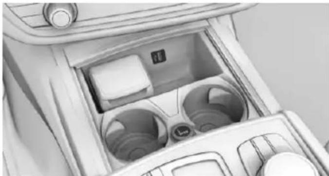
natural_image
Interior view of a car air intake console with visible fan and door (no text or symbols)Rear center console
If not equipped with rear console:
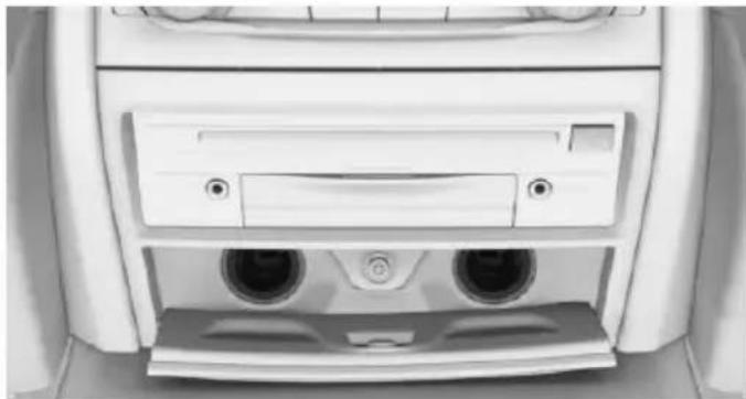
natural_image
Close-up of a car front panel showing rear seats and ventilation slots (no text or symbols visible)Open the cover. Remove the cover or cigarette lighter.
To close the cover, tap it again.
If equipped with rear console:
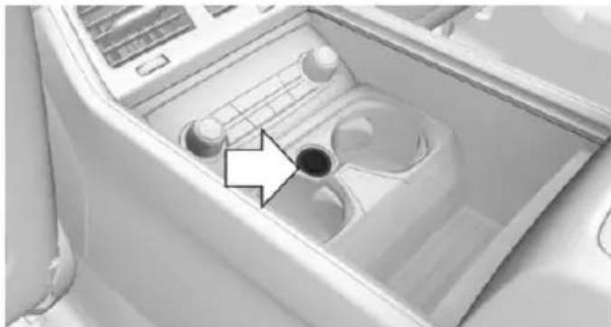
natural_image
Interior view of a car gear shift lever with no visible text or symbolsThe socket is located between the cup holders under the cover.
Front center armrest
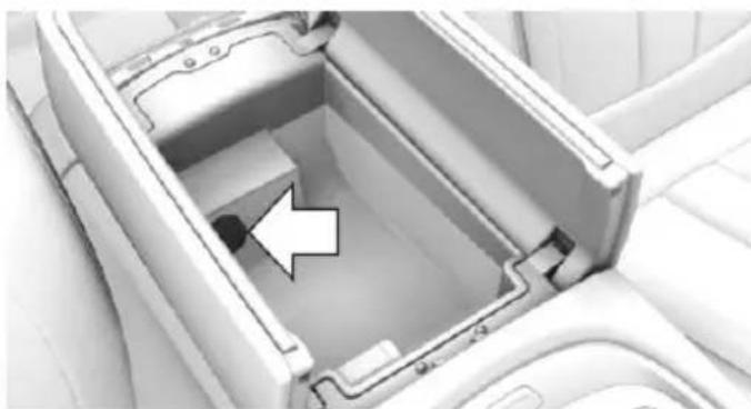
natural_image
Interior view of a car air conditioner unit with an arrow pointing to the interior space (no text or symbols visible)Remove the cover.
Rear center armrest
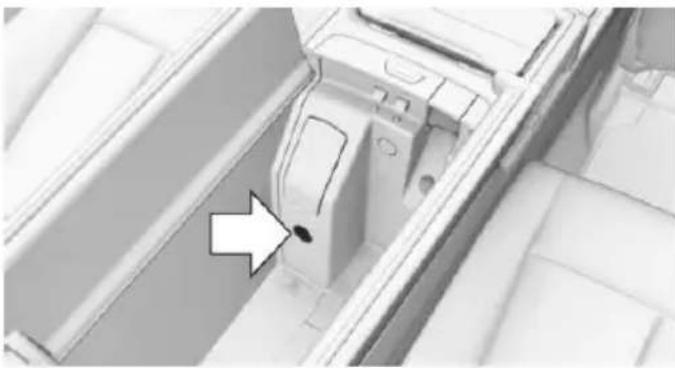
natural_image
Interior view of a vehicle showing a car's side panel and dashboard (no text or symbols visible)There is a socket in the storage compartment in the center armrest, arrow.
In the trunk
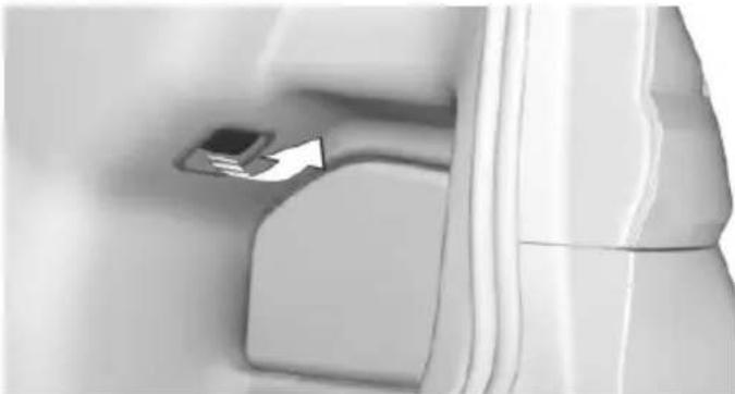
natural_image
Close-up of a mechanical component with a small metallic part inserted, no visible text or symbolsFold open the cover.
USB interface
The concept
External devices with USB port can be connected to the USB interface.
The following audio devices can be connected:
▶ Mobile phones and smartphones supported by the USB interface.
The snap-in adapter features a separate USB port that is automatically connected when a compatible mobile phone is inserted.
▶ Audio devices with USB port, e.g. MP3 player.
▶ USB storage devices.
Common file systems are supported. FAT32 and exFAT are the recommended formats.
Information about compatible USB devices can be found at www.bmwusa.com/bluetooth.
The following applications are possible:
▶ Exporting and importing profiles, refer to page 58.
▶ Listening to music files via USB audio.
▶ Watching video films via USB video.
▶ Loading of software updates, refer to page 46.
Information
Observe the following when connecting:
Do not use force when plugging the connector into the USB interface.
▶ Use a flexible adapter cable.
▶ Protect the USB device against mechanical damage.
Do not use the USB interface for recharging external devices.
Due to the large number of audio devices available on the market, it cannot be guaranteed that every USB device is operable on the vehicle.
Do not expose audio devices to extreme environmental conditions, such as very high temperatures; refer to the audio device operating instructions.
Due to the different configurations of audio and video files, e.g., bit rates greater than 256 kbit/s, or the many different compression techniques, proper playback cannot be guaranteed in all cases.
The connected audio device is supplied with a max. power of 1 A if supported by the device. Therefore, do not additionally connect the device to a socket inside the vehicle; otherwise, playback may be compromised.
Not compatible USB devices:
▶ USB hard drives.
▶ USB hubs.
▶ USB memory card readers with multiple inserts.
▷ HFS-formatted USB devices.
▶ MTP devices.
▶ Devices such as fans or lights.
In the center armrest
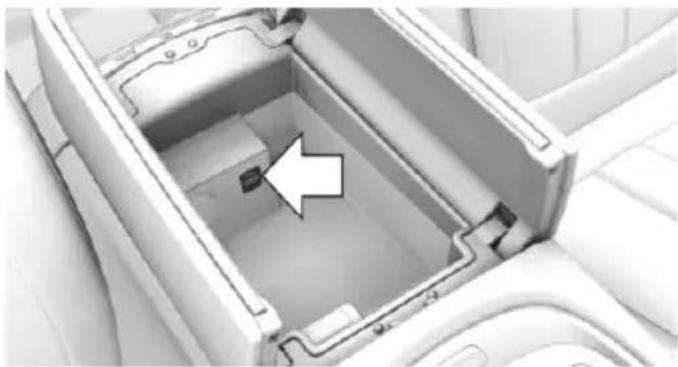
natural_image
Interior view of a car air conditioner unit with an arrow pointing to the interior space (no text or symbols visible)The USB interface is located in the center arm-rest.
In the center console
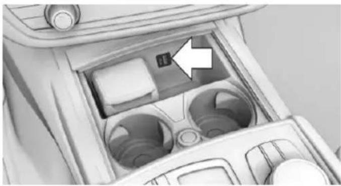
natural_image
Interior view of a car airway with visible vent and door, no text or symbols presentThe USB interface is located in the center console.
Through-loading system
General information
The through-loading system allows the transport of long objects, such as skies.
Opening through-loading without comfort seats
- Fold down the center armrest.
- Remove flap.
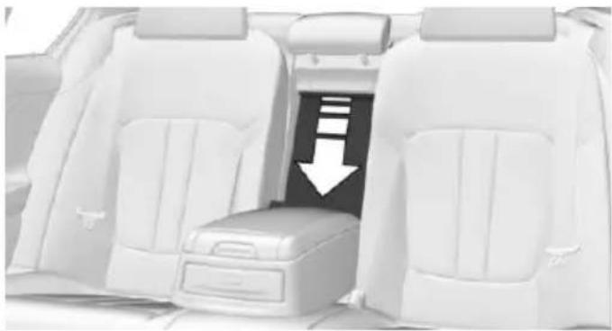
natural_image
Interior view of a car showing the rear seat, front seats, and a highlighted lower portion with an arrow (no text or symbols)- Pull handle down, arrow 1, and fold panel forward, arrow 2.
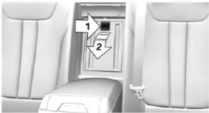
text_image
1 2Opening through-loading with comfort seats
- If equipped with rear console: fold down center armrest.
- If equipped with rear console: push cover upward until it engages.
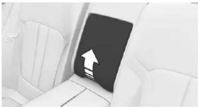
natural_image
Interior view of a white car with a black door and white arrow pointing upward (no text or symbols)- Pull on the loop.
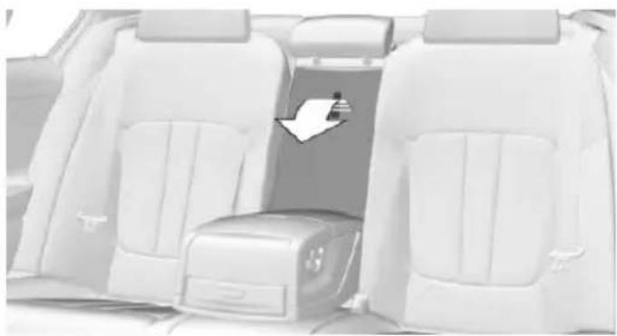
natural_image
Interior view of a car showing the rear seats and seatbelt, with a white arrow pointing to a specific side panel (no text or symbols visible)Folding table in the rear
General information
There is a folding table in the center armrest of the rear console.
Information

WARNING
A folded-out folding table protrudes into the vehicle's interior and, in case of accident, braking or evasive maneuvers can cause injuries. Objects on the table can be thrown around the car's interior while driving. There is risk of injuries. Do not unfold or use folding table while driving.
Folding the folding table open
- Open the center armrest, refer to page 227.
- Grasp the folding table in the rear and pull forward out from the center armrest.
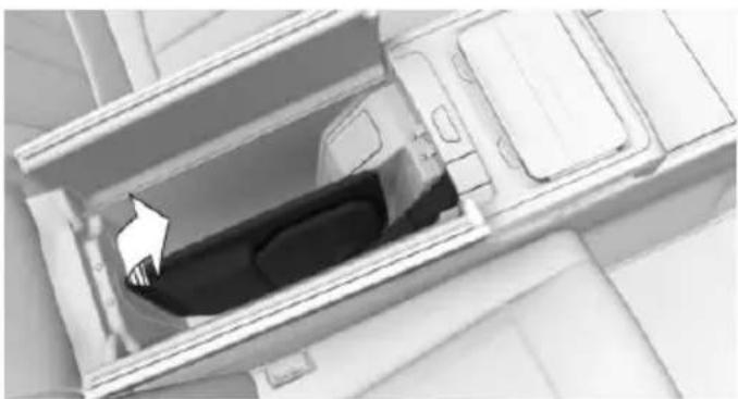
natural_image
Interior view of a mechanical device with a highlighted component (no visible text or symbols)- Fold the folding table down.
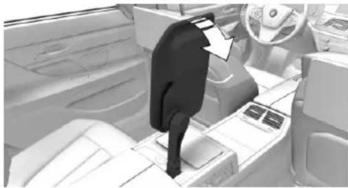
natural_image
Interior view of a car dashboard with a person adjusting the seat, showing steering wheel and dashboard (no text or symbols visible)The folding table can be rotated by 90^ or 180^ to the left and can be enlarged.
Proceed in reverse order to fold in the folding table.
Rear cooler
Information

WARNING
The cover of the opened cooler protrudes into the car's interior. Injuries can occur in the event of an accident, braking or evasive maneuver. The content of the cooler can be thrown into the car's interior and injure occupants. There is risk of injuries. Close the cooler after use when driving.
Opening the rear cooler
- Fold down the center armrest.
- Opening the through-loading system, refer to page 222.
- Press the opener and fold the cover forward.
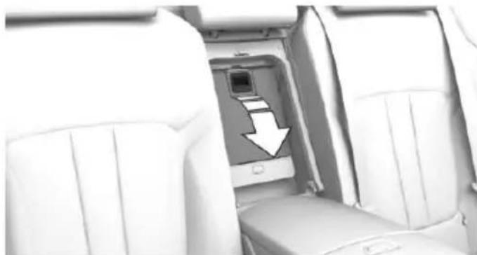
natural_image
Interior view of a car cabin with white seats and a digital camera module, no visible text or symbolsSwitching on
The cooler can be operated at two levels.
-
Turn on operations.
-
Press button once for each cooling level.

The highest cooling power is active when two LEDs are lit.
If the cooler was switched on the last time operating readiness was switched off, it will likewise be switched on the next time operating readiness is switched on.
Switch off
Press button repeatedly until the LEDs go out.
Removing
- Pull on the rear handle.
- Pull cooler backward and remove it.
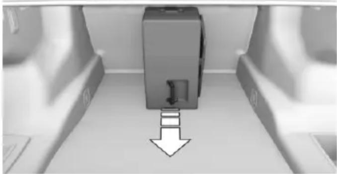
natural_image
3D rendered diagram of a mechanical device with a downward arrow indicating motion or force (no text or symbols)- Fold the cover back.
Installing
- Open the cover.
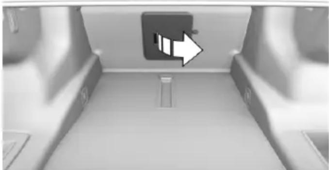
natural_image
Interior view of a vehicle showing a white arrow pointing to a rectangular component on the side (no text or symbols visible)- Pull on the rear handle and push the cooler into the guide rails.
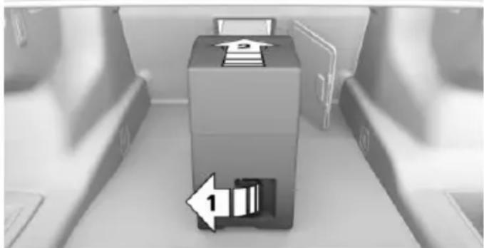
natural_image
3D illustration of a box with a document icon and an arrow pointing to it, placed on a surface with blurred background objects (no text or symbols)- Fold the handle back again.
Malfunction
The cooler cannot be switched on or switches off, e.g., when the cooling system overheats or if the battery voltage is low. One of the LEDs flashes.
Remedy the problem
- If necessary, allow the refrigerator cooling system to cool down.
- Start the engine.
- Switch on cooler.
If the LED flashes even after a short time, have the cooler checked by a dealer's service center or another qualified service center or repair shop.
Ski and snowboard bag
The ski and snowboard bag is contained in a protective jacket in the trunk.
Follow the installation and operation instructions included in the protective jacket.
If equipped with emergency wheel: remove the emergency wheel from the vehicle to mount the ski and snowboard bag.
Storage compartments
Vehicle features and options
This chapter describes all standard, country-specific and optional features offered with the series. It also describes features that are not necessarily available in your car, e.g., due to the selected options or country versions. This also applies to safety-related functions and systems. The respectively applicable country provisions must be observed when using the respective features and systems.
Information

WARNING
Loose objects in the car's interior can be thrown into the car's interior while driving, e.g. in the event of an accident or during braking and evasive maneuvers. There is risk of injuries. Secure loose objects in the car's interior.

CAUTION
Anti-slip pads such as anti-slip mats can damage the dashboard. There is risk of property damage. Do not use anti-slip pads.
Storage compartments
The following storage compartments are available in the vehicle interior:
▶ Glove compartment on the front passenger side, refer to page 225.
▶ Glove compartment on the driver's side, refer to page 226.
▶ Compartments in the doors, refer to page 226.
Storage compartment on the center console, refer to page 226.
▶ Center armrest, refer to page 227.
Storage compartment in the rear, refer to page 227.
Storage compartment in the rear center console, refer to page 226.
▷ Pockets on the backrests of the front seats.
Glove compartment
Front passenger side
Information

WARNING
Folded open, the glove compartment protrudes in the car's interior. Objects in the glove compartment can be thrown into the car's interior while driving, e.g. in the event of an accident or during braking and evasive maneuvers. There is risk of injuries. Always close the glove compartment immediately after using it.
Opening
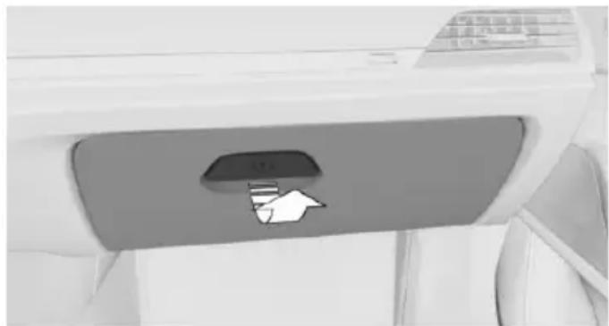
natural_image
Close-up of a white aircraft fuselage with a gray panel and a white arrow pointing to the side (no text or symbols visible)Pull the handle.
The light in the glove compartment switches on.
Closing
Fold cover closed.
Locking
The glove compartment can be locked with an integrated key. This prevents access to the glove compartment.
After the glove compartment is locked, the remote control can be handed over, such as at a hotel, without the integrated key.
Driver's side
Information

WARNING
Folded open, the glove compartment protrudes in the car's interior. Objects in the glove compartment can be thrown into the car's interior while driving, e.g. in the event of an accident or during braking and evasive maneuvers. There is risk of injuries. Always close the glove compartment immediately after using it.
Opening
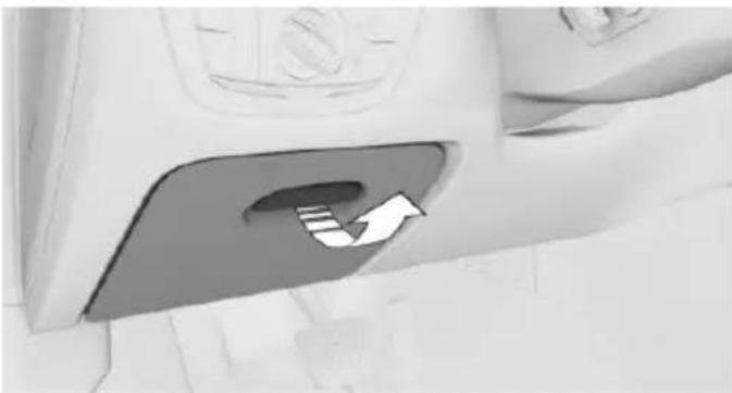
natural_image
Close-up of a car interior showing a directional arrow icon on the backrest (no text or symbols)Pull the handle.
Closing
Fold cover closed.
Compartments in the doors

WARNING
Breakable object, e.g. glass bottle, can break in the event of an accident. Broken glass can be scattered in the car's interior. There is
risk of injuries. Do not stow any breakable objects in the car's interior.
Storage compartment on the center console
Opening
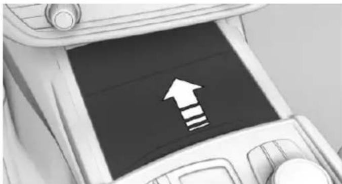
natural_image
Interior view of a car dashboard with a black screen showing a white upward arrow and three horizontal stripes (no text or symbols)Push the cover forward until it engages behind the cup holders. Push the cover forward again until it engages behind the storage compartment.
Closing
Touch the cover on the handle bar. It slides up to the cup holders toward the back. Another touch closes the storage compartment completely.
Storage compartment in the rear center console
The rear center console contains a storage compartment.
Storage compartment in the rear
Opening
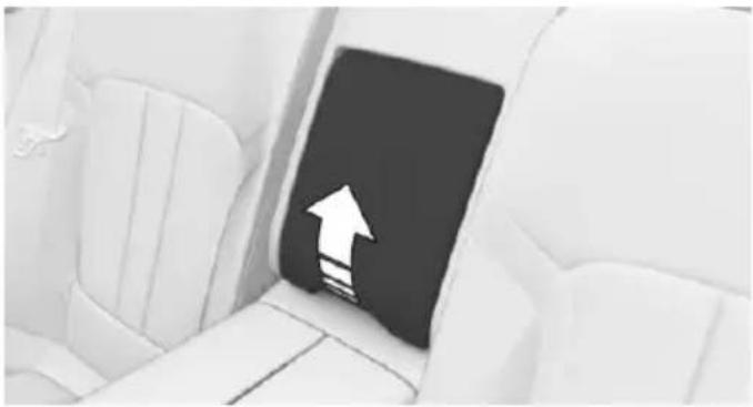
natural_image
Interior view of a white car with a black door and white arrow pointing upward (no text or symbols)Push the cover up until it engages. There is a storage compartment underneath.
Closing
Press the cover upward to close it. The cover slides down.
Center armrest
Front
Overview
A storage compartment is located in the center armrest between the seats.
Opening
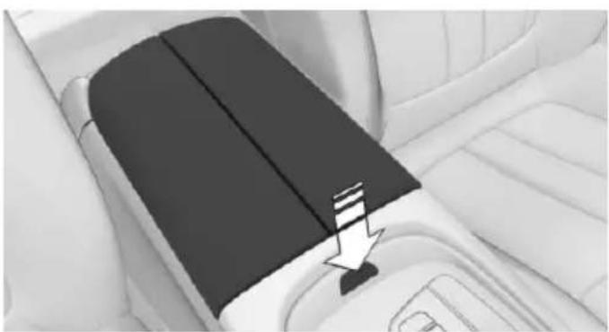
natural_image
Interior view of a car seatbelt with a black seat cover and a white seatbelt, showing no text or symbols.Press button.
Closing
Press cover down until it engages.
Rear
Overview
A storage compartment is located in the center armrest between the seats.
Opening
Depending on the equipment, one of the following variants is installed:
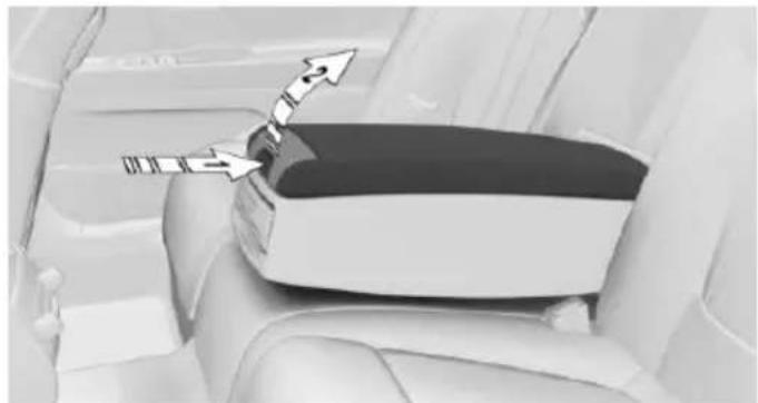
natural_image
Interior view of a car seatbelt with directional arrows indicating movement (no text or symbols)Press button, arrow 1, and fold the cover up, arrow 2.
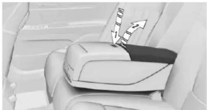
natural_image
Interior view of a car seatbelt with directional arrows indicating movement (no text or symbols)Press button, arrow 1, and fold the cover up, arrow 2.

natural_image
Interior view of a car seatbelt with a hand cursor pointing to the side panel (no text or symbols visible)Press button.
Closing
Press cover down until it engages.
Cupholders
Information

WARNING
Unsuitable containers in the cup holder and hot beverages can damage the cup holder and increase the risk of injuries in the event of an accident. There is risk of injuries or risk of property damage. Use light-weight, unbreakable, and sealable containers. Do not transport hot beverages. Do not force objects into the cup holder.
Front
Opening
- Push the cover forward until it engages behind the cup holders.
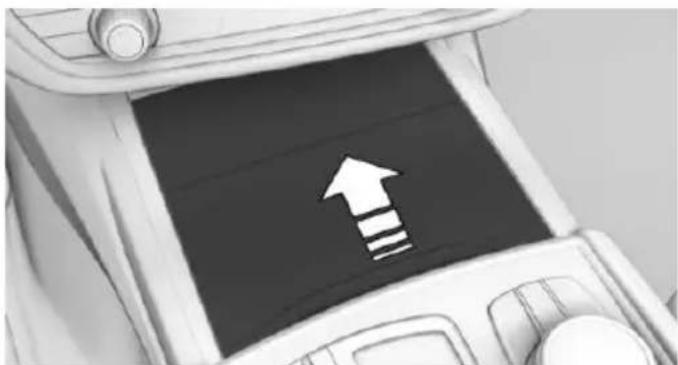
natural_image
Illustration of a car interior with a directional arrow and three horizontal stripes on a dark screen (no text or symbols)- Two cupholders are located in the center console.
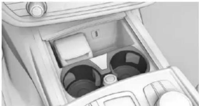
natural_image
Interior view of a car intake manifold with two circular ventricles (no text or symbols visible)Rear
Information

CAUTION
With an open cup holder, the center armrest cannot be folded back up. There is risk of property damage. Press back the covers before the center armrest is folded up.
Opening
If not equipped with rear console:
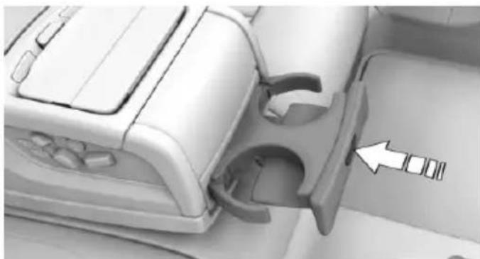
natural_image
Close-up of a mechanical device with a highlighted internal component and an arrow indicating a specific part (no text or symbols visible)Press button to open.
Slide cup holders rearward to close.
If equipped with rear console:
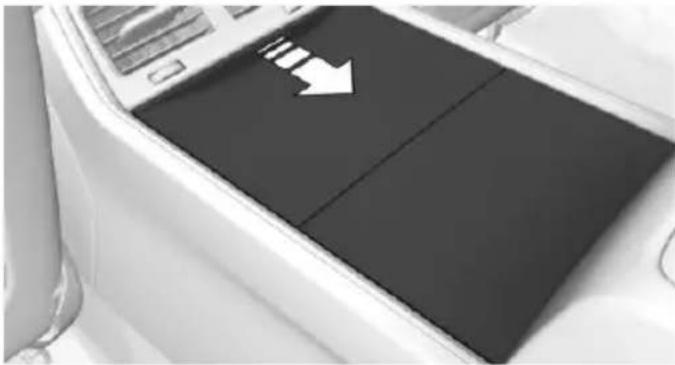
natural_image
Close-up of a car front panel with a white arrow pointing to the side panel (no text or symbols visible)Slide cover rearward to open.
To close: slide the cover backward. The cover slides forward.
Clothes hooks

WARNING
Clothing articles on the clothes hooks can obstruct the view while driving. There is risk of an accident. When suspending clothing articles from the hooks, ensure that they will not obstruct the driver's view.

WARNING
Improper use of the clothes hooks can lead to a danger of objects flying about during braking and evasive maneuvers. There is risk of injuries and risk of property damage. Only hang lightweight objects, e.g. clothing articles, from the clothes hooks.
The clothes hooks are located in the grab handles in the rear and on the door pillar in the rear.
Storage compartments in the trunk
Multi-function hook
Information

WARNING
Improper use of the multifunction hooks can lead to a danger of objects flying about during braking and evasive maneuvers. There is risk of injuries and risk of property damage. Only hang lightweight objects, e.g. shopping bags, from the multifunction hooks. Only transport heavy luggage in the trunk if it has been appropriately secured.
Overview
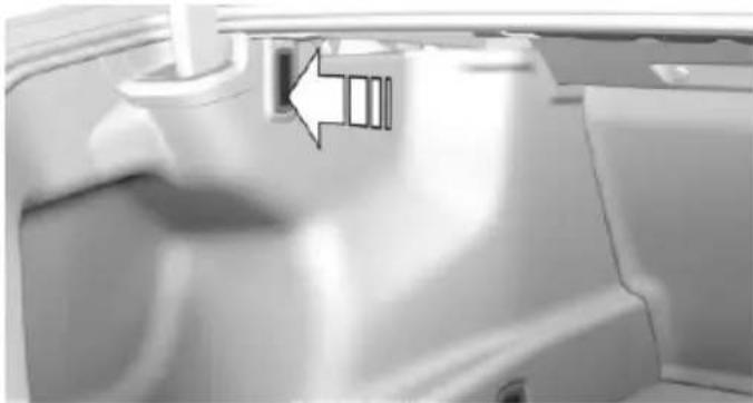
natural_image
Close-up of a car's front panel showing a small component and a directional arrow (no text or symbols)A multi-function hook is located on the left side in the trunk. Press on the multi-function hook and turn until it engages.
Storage compartment on the right side
A storage compartment is available on the right side of the cargo area.
Left side storage compartment
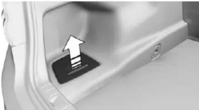
natural_image
Close-up of a car door handle with an upward arrow indicator (no text or symbols)Pull the handle.
Lashing eyes in the cargo area
To secure the cargo, refer to page 238, there are lashing eyes in the cargo area.
Storage compartment below cargo floor panel
There is a storage compartment under the cargo floor panel.
Fold up the cargo floor panel.
text_image
Online Edition for Part no. 0140 2 964 330 - VI/15Driving tips
This chapter provides you with information useful in dealing with specific driving and operating modes.
Things to remember when driving
Vehicle features and options
This chapter describes all standard, country-specific and optional features offered with the series. It also describes features that are not necessarily available in your car, e.g., due to the selected options or country versions. This also applies to safety-related functions and systems. The respectively applicable country provisions must be observed when using the respective features and systems.
Breaking-in period
General information
Moving parts need time to adjust to one another (break-in time).
The following instructions will help accomplish a long vehicle life and good efficiency.
During break-in, do not use the Launch Control, refer to page 109.
Engine, transmission, and axle drive
Up to 1,200 miles/2,000 km
Do not exceed the maximum engine and road speed:
For gasoline engine 4,500 rpm and 100 mph/160 km/h.
Avoid full load or kickdown under all circumstances.
From 1,200 miles/2,000 km
The engine and vehicle speed can gradually be increased.
Tires
Tire traction is not optimal due to manufacturing circumstances when tires are brand-new;
they achieve their full traction potential after a break-in time.
Drive conservatively for the first 200 miles/300 km.
Brake system
Brakes require an initial break-in period of approx. 300 miles/500 km to achieve optimal performance between brake discs and brake pads. Drive moderately during this break-in period.
Following part replacement
The same break-in procedures should be observed if any of the components above-mentioned have to be renewed in the course of the vehicle's operating life.
General driving notes
Closing the trunk lid

WARNING
An open trunk lid protrudes from the vehicle and can endanger occupants and other traffic participants or damage the vehicle in the event of an accident, braking or evasive maneuvers. In addition, exhaust fumes may enter the vehicle interior. There is risk of injuries or risk of property damage. Do not drive with the trunk lid open.
If driving with the tailgate open cannot be avoided:
▶ Close all windows and the glass sunroof.
▶ Greatly increase the air flow from the vents.
▶ Drive moderately.
Hot exhaust system

WARNING
During driving operation, high temperatures can occur underneath the body, e.g. caused by the exhaust gas system. If combustible materials, such as leaves or grass, come in contact with hot parts of the exhaust gas system, these materials can ignite. There is risk of injuries or risk of property damage.
Do not remove the heat shields installed and never apply undercoating to them. Make sure that no combustible materials can come in contact with hot vehicle parts in driving operation, idle or during parking. Do not touch the hot exhaust system.
Mobile communication devices in the vehicle

WARNING
Vehicle electronics and mobile phones can influence one another. There is radiation due to the send operations of mobile phones. There is risk of injuries or risk of property damage. If possible, in the car's interior use only mobile phones with direct connections to an exterior antenna in order to exclude mutual disturbance and deflect the radiation from the car's interior.
Hydroplaning
On wet or slushy roads, a wedge of water can form between the tires and road surface.
This phenomenon is referred to as hydroplaning. It is characterized by a partial or complete loss of contact between the tires and the road surface, ultimately undermining your ability to steer and brake the vehicle.
Driving through water

CAUTION
When driving too quickly through too deep water, water can enter into the engine compartment, the electrical system or the
transmission. There is risk of property damage. When driving through water, do not exceed the maximum indicated water level and the maximum speed for driving through water.
Drive through calm water only and only if it is not deeper than 9.8 inches/25 cm and at this height, no faster than walking speed, up to 3 mph/5 km/h.
Braking safely
Your vehicle is equipped with ABS as a standard feature.
Applying the brakes fully is the most effective way of braking in situations needed.
Steering is still responsive. You can still avoid any obstacles with a minimum of steering effort.
Pulsation of the brake pedal and sounds from the hydraulic circuits indicate that ABS is in its active mode.
In certain braking situations, the perforated brake discs can cause functional problems. However, this has no effect on the performance and operational reliability of the brake.
Objects in the movement area around pedals and floor area

WARNING
Objects in the driver's floor area can limit the pedal distance or block a depressed pedal. There is risk of an accident. Stow objects in the vehicle such that they are secured and cannot enter into the driver's floor area. Use floor mats that are suitable for the vehicle and can be safely attached to the floor. Do not use loose floor mats and do not layer several floor mats. Make sure that there is sufficient clearance for the pedals. Ensure that the floor mats are securely fastened again after they were removed, e.g. for cleaning.
Driving in wet conditions
When roads are wet, salted, or in heavy rain, press brake pedal ever so gently every few miles.
Ensure that this action does not endanger other traffic.
The heat generated in this process helps dry the brake discs and pads.
In this way braking efficiency will be available when you need it.
Hills

WARNING
Light but consistent brake pressure can lead to high temperatures, brakes wearing out and possibly even brake failure. There is risk of an accident. Avoid placing excessive stress on the brake system.

WARNING
In idle or with the engine switched off, safety-relevant functions are restricted or not available anymore, e.g. braking effect of the engine or braking force and steering support. There is risk of an accident. Do not drive in idle or with the engine switched off.
Drive long or steep downhill gradients in the gear that requires least braking efforts. Otherwise the brakes may overheat and reduce brake efficiency.
You can increase the engine's braking effect by shifting down, going all the way to first gear, if needed.
Brake disc corrosion
Corrosion on the brake discs and contamination on the brake pads are furthered by the following circumstances:
▶ Low mileage.
▶ Extended periods when the vehicle is not used at all.
▶ Infrequent use of the brakes.
Corrosion will built up when the maximum pressure applied to the brake pads during braking is not reached - thus discs don't get cleaned.
Corrosion buildup on the brake discs will cause a pulsating effect on the brakes in their response - generally that cannot be corrected.
Condensation under the parked vehicle
When using the automatic climate control, condensation water develops collecting underneath the vehicle.
These traces of water under the vehicle are normal.
Loading
Vehicle features and options
This chapter describes all standard, country-specific and optional features offered with the series. It also describes features that are not necessarily available in your car, e.g., due to the selected options or country versions. This also applies to safety-related functions and systems. The respectively applicable country provisions must be observed when using the respective features and systems.
Information

WARNING
High gross weight can overheat the tires, damage them internally, and cause a sudden drop in tire inflation pressure. There is risk of an accident. Pay attention to the permitted load capacity of the tires and never exceed the permitted gross weight.

CAUTION
Fluids in the cargo area can cause damage. There is risk of property damage. Make sure that no fluids leak in the cargo area.

WARNING
Loose objects in the car's interior can be thrown into the car's interior while driving, e.g. in the event of an accident or during braking and evasive maneuvers. There is risk of injuries. Secure loose objects in the car's interior.
Determining the load limit
- Locate the following statement on your vehicle's placard:
The combined weight of occupants and cargo should never exceed XXX kg
or YYY lbs. Otherwise, damage to the vehicle and unstable driving situations may result.
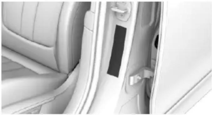
natural_image
Interior view of a car showing the door, seat, and door panel (no text or symbols visible)- Determine the combined weight of the driver and passengers that will be riding in your vehicle.
- Subtract the combined weight of the driver and passengers from XXX kilograms or YYY pounds.
- The resulting figure equals the available amount of cargo and luggage load capacity.
For example, if the YYY amount equals 1,000 lbs and there will be four 150 lbs passengers in your vehicle, the amount of available cargo and luggage load capacity is 400 lbs: 1,000 lbs minus 600 lbs = 400 lbs.
- Determine the combined weight of luggage and cargo being loaded on the vehicle. That weight may not safely exceed the available cargo and luggage load capacity calculated in Step 4.
Load

text_image
+ ≦ Max. Load + ≦ Max. Load + ≦ Max. LoadThe maximum load is the sum of the weight of the occupants and the cargo.
The greater the weight of the occupants, the less cargo that can be transported.
Stowing cargo
▶ Cover sharp edges and corners on the cargo.
▶ Heavy cargo: stow as far forward as possible, directly behind and at the bottom of the rear passenger seat backrests.
▶ Very heavy cargo: when the rear seat is not occupied, secure each of the outer safety belts in the opposite buckle.
Securing cargo
Lashing eyes in the cargo area
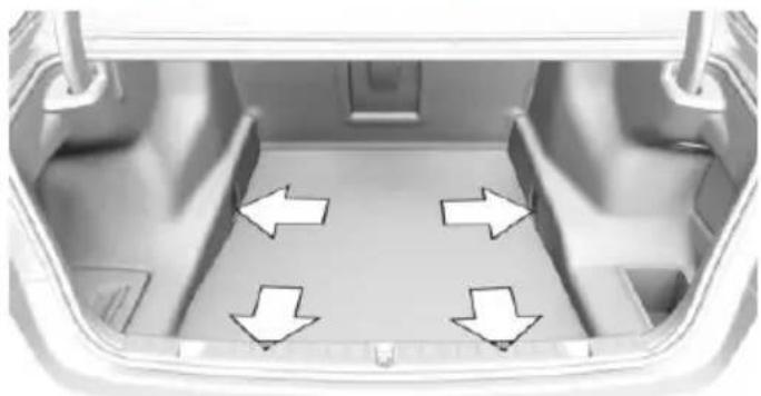
natural_image
Interior view of a car trunk with four directional arrows indicating movement or flow (no text or symbols)To secure the cargo there are four lashing eyes in the cargo area.
Securing cargo
WARNING Improperly
Improperly stowed objects can shift and be thrown into the car's interior, e.g. in the event of an accident or during braking and evasive maneuvers. Vehicle occupants can be hit and injured. There is risk of injuries. Stow and secure objects and cargo properly.
▶ Smaller and lighter items: secure with retaining straps or with a cargo net or draw straps.
Larger and heavy objects: secure with cargo straps.
Cargo straps, cargo netting, retaining straps or draw straps on the lashing eyes in the trunk.
Roof-mounted luggage rack
Information
Installation only possible in roof drip molding with flaps. Further information is available from a dealer's service center or another qualified service center or repair shop.
Roof racks are available as special accessories.
Securing
Follow the installation instructions of the roof rack.
Roof drip rail with flaps
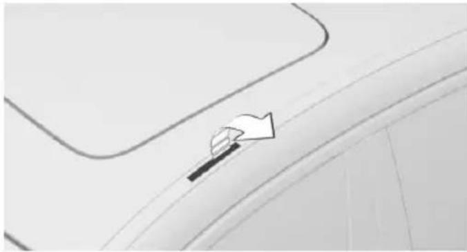
natural_image
Close-up of a car's side profile with a curved ramp and arrow indicator (no text or symbols)The anchorage points are located in the roof drip rail above the doors.
Fold the cover outward.
Mounting
Be sure that adequate clearance is maintained for tilting and opening the glass sunroof.
Magnetic roof-mounted luggage rack
Because of the aluminum roof, magnetic roof-mounted luggage racks cannot be used.
Loading
Because roof racks raise the vehicle's center of gravity when loaded, they have a major effect on vehicle handling and steering response.
Therefore, note the following when loading and driving:
Do not exceed the approved roof/axle loads and the approved gross vehicle weight.
Be sure that adequate clearance is maintained for tilting and opening the glass sunroof.
▶ Distribute the roof load uniformly.
The roof load should not extend past the loading area.
▶ Always place the heaviest pieces on the bottom.
▶ Secure the roof luggage firmly, e.g., tie with ratchet straps.
Do not let objects project into the opening path of the trunk lid.
▶ Drive cautiously and avoid sudden acceleration and braking maneuvers. Take corners gently.
Saving fuel
Vehicle features and options
This chapter describes all standard, country-specific and optional features offered with the series. It also describes features that are not necessarily available in your car, e.g., due to the selected options or country versions. This also applies to safety-related functions and systems. The respectively applicable country provisions must be observed when using the respective features and systems.
General information
Your vehicle contains advanced technology for the reduction of fuel consumption and emissions.
Fuel consumption depends on a number of different factors.
Carrying out certain measures, such as a moderate driving style and regular maintenance, can influence fuel consumption and the environmental impact.
Remove unnecessary cargo
Additional weight increases fuel consumption.
Remove attached parts following use
Remove auxiliary mirrors, roof or rear luggage racks which are no longer required following use.
Attached parts on the vehicle impair the aerodynamics and increase the fuel consumption.
Close the windows and glass sunroof
Driving with the glass sunroof and windows open results in increased air resistance and raises fuel consumption.
Tires
General information
Tires can affect fuel consumption in various ways, e.g., tire size may influence fuel consumption.
Check the tire inflation pressure regularly
Check and, if needed, correct the tire inflation pressure at least twice a month and before starting on a long trip.
Low tire inflation pressure increases rolling resistance and thus raises fuel consumption and tire wear.
Drive away without delay
Do not wait for the engine to warm-up while the vehicle remains stationary. Start driving right away, but at moderate engine speeds.
This is the quickest way of warming the cold engine up to operating temperature.
Look well ahead when driving
Avoid unnecessary acceleration and braking.
By maintaining a suitable distance to the vehicle driving ahead of you.
Driving smoothly and proactively reduces fuel consumption.
Avoid high engine speeds
As a rule: driving at low engine speeds lowers fuel consumption and reduces wear.
If necessary, observe the gear shift indicator, refer to page 120, of the vehicle.
Use coasting conditions
When approaching a red light, take your foot off the accelerator and let the vehicle coast to a halt.
For going downhill take your foot off the accelerator and let the vehicle roll.
The flow of fuel is interrupted while coasting.
Switch off the engine during longer stops
Switch off the engine during longer stops, e.g., at traffic lights, railroad crossings or in traffic congestion.
Auto Start/Stop function
The Auto Start/Stop function of your vehicle automatically switches off the engine during a stop.
If the engine is switched off and then restarted rather than leaving the engine running constantly, fuel consumption and emissions are reduced. Savings can begin within a few seconds of switching off the engine.
In addition, fuel consumption is also determined by other factors, such as driving style, road conditions, maintenance or environmental factors.
Switch off any functions that are not currently needed
Functions such as seat heating and the rear window defroster require a lot of energy and reduce the range, especially in city and stop-and-go traffic.
Switch off these functions if they are not needed.
The ECO PRO driving program supports the energy conserving use of comfort features. These functions are automatically deactivated partially or completely.
Have maintenance carried out
Have vehicles maintained regularly to achieve optimal vehicle efficiency and service life. BMW recommends that maintenance work be performed by a BMW dealer's service center.
For information on the BMW Maintenance System, refer to page 279.
ECO PRO
The concept
ECO PRO supports a driving style that saves on fuel consumption. For this purpose, the engine control and comfort features, e. g. the climate control output, are adjusted.
Under certain conditions the engine is automatically decoupled from the transmission in the D selector lever position. The vehicle continues traveling with the engine idling to reduce fuel consumption. Selector lever position D remains engaged.
In addition, context-sensitive instructions are displayed to assist with an optimized fuel consumption driving style.
The achieved extended range is displayed in the instrument cluster as bonus range.
Overview
The system includes the following EfficientDynamics functions and displays:
▶ ECO PRO bonus range, refer to page 243.
▶ ECO PRO tips driving instruction, refer to page 243.
▶ ECO PRO climate control, refer to page 242.
▶ ECO PRO route-ahead assistant driving instruction, refer to page 244.
▶ ECO PRO coasting driving status, refer to page 245.
▷ ECO PRO driving style analysis, refer to page 246.
Activating ECO PRO
Press button. ECO PRO is displayed in the instrument cluster.
Configuring ECO PRO INDIVIDUAL
Opening via the Driving Dynamics Control
- Activate ECO PRO.
- "Configure ECO PRO INDIVIDUAL"
Opening via iDrive
- "My Vehicle"
- "Vehicle settings"
- "Driving Experience Control"
- "Configure ECO PRO INDIVIDUAL"
ECO PRO notes
Activate the ECO PRO limit:
"ECO PRO speed warning"
An ECO PRO tip is displayed if the speed of the set ECO PRO limit is exceeded.
Adjust the ECO PRO limit speed:
▷ "Tip at:"
Activating ECO PRO functions
Adjust, which ECO PRO functions should be used.
▶ "Coasting"
▶ "ECO PRO seat climate control"
▶ "ECO PRO climate control"
▶ "ECO PRO sight"
▶ "Route-ahead assistant"
Coasting
Fuel-efficiency can be optimized by disengaging the engine and Coasting with the engine idling.
ECO PRO seat heating
The output of seat heating and possibly seat ventilation is reduced on activation of ECO PRO.
ECO PRO climate control
"ECO PRO climate control"
Climate control is set to be fuel-efficient.
By making a slight change to the set temperature, or slowly adjusting the rate of heating or cooling of the car's interior, fuel consumption can be economized.
The mirror heating is made available when outside temperatures are very cold.
Route-ahead assistant
The route-ahead assistant detects and indicates route sections ahead of the vehicle.
Resetting the settings
Reset ECO PRO INDIVIDUAL to the standard settings:
Select and confirm "Reset to ECO PRO STANDARD".
Display in the instrument cluster
Display
When ECO PRO mode is activated, the display switches to a special configuration.
Some of the displays may differ from the display in the instrument cluster.
Blue bar segments symbolize the gained bonus range in stages.
ECO PRO bonus range
An adjusted driving style helps you extend your driving range. This may be displayed as the bonus range in the instrument cluster.
The bonus range is shown in the range display.
The bonus range is automatically reset every time the vehicle is refueled.
Efficiency display
Display in the instrument cluster
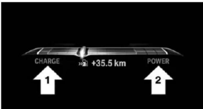
text_image
CHARGE +35.5 km POWER 1 2Display in the instrument cluster with expanded scope
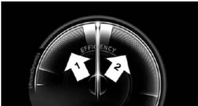
text_image
EFFICIENCY 1 2 EfficientDynamicsA mark in the efficiency display informs about the current driving style.
Mark in the area of arrow 1: display of the energy recovered by coasting or when braking.
Mark in the area of arrow 2: display when accelerating.
ECO PRO tip, driving tip
As soon as one of the conditions for efficient driving is no longer fulfilled, respective driving instructions are displayed as a symbol in the instrument cluster.

The arrow indicates that the driving style can be adjusted to be more fuel efficient by backing off the accelerator for instance.
The ECO PRO tip is not displayed anymore as soon as the conditions for efficient driving are fulfilled again.
ECO PRO tip, symbols
Symbol Measure

For an efficient driving style:
Give less gas, decelerate in advance or reduce speed to selected ECO PRO speed.

Steptronic transmission: shift from M/S to D.
Indications on the Control Display
Displaying EfficientDynamics info
The current efficiency of the ECO PRO systems can be shown on the Control Display.
- "My Vehicle"
- "Technology in action"
- "EfficientDynamics"
The following systems are displayed:
Auto Start/Stop function.
▶ Energy recovery.
▶ Coasting.
Displaying fuel consumption history
The average consumption on the route coasted as well as the duration for which the auto start/stop function switched off the engine can be displayed.
- "My Vehicle"
- "Technology in action"
- "EfficientDynamics"
Vertical bars show consumption for the selected route.
Selecting route length
button.
2. Select desired route length or scaling.

Resetting fuel consumption history
button.
2. "Reset consumption history"

Route-ahead assistant
The concept
The system helps to conserve fuel and promotes a proactively driving style. It can detect certain upcoming sections of the journey based on the navigation data and alert the driver to them in good time.
The detected route sections, such as built-up areas or changes of road require the driver to reduce speed.
General information
This alert is issued even if the upcoming route section cannot yet be detected while driving.
The alert is displayed until the route section is reached.
If an alert is received, the vehicle's speed and its fuel consumption can be reduced by backing off the accelerator and coasting until the route section is reached.
Depending on the situation, the system also uses the engine brake automatically with a pausing of the coast, refer to page 245, function.
Functional requirements
This function is available in ECO PRO mode.
The system depends on the timeliness and quality of the navigation data.
The navigation data can be updated.
Display
Display in the instrument cluster

The note about a route section ahead is made as recommendation to let the vehicle coast to a halt.
An additional symbol indicates the detected route section.
Symbol Upcoming route section

Intersection or turning maneuver, exit from an expressway.

Curve.

Traffic circle.
Display in the Head-up Display

The route ahead alert can also be displayed in the Head-Up Display.
Indications on the Control Display
natural_image
Abstract white line drawing on black background, resembling a stylized road or road sign (no text or symbols)In the indicator of the driving style analysis shown on the Control Display, a note is displayed if a corresponding route section is upcoming.
Call up the display of the driving style analysis:
- "My Vehicle"
- "Technology in action"
- "Driving style analysis"
Using the route-ahead assistant
An upcoming route section is displayed:
- Back off the accelerator.
- Allow the vehicle to coast until the route section indicated is reached.
- If necessary, adjust speed by braking.
System limits
The system is not available in the following situations:
▶ Speed less than 30 mph, approx. 50 km/h.
▶ Temporary and variable speed limit, e.g., for road works.
Quality of navigation data inadequate.
▶ Cruise control active.
Coasting
The concept
The system helps to conserve fuel.
To do this, under certain conditions the engine is automatically decoupled from the transmission when selector lever position D is set. The vehicle continues traveling with the engine idling to reduce fuel consumption. Selector lever position D remains engaged.
This driving condition is referred to as coasting.
As soon as you step on the brake or accelerator pedal, the engine is automatically coupled again.
Information
Coasting is a component of the ECO PRO, refer to page 241, driving mode.
Coasting is automatically activated when ECO PRO mode is called via the Driving Dynamics Control.
The function is available in a certain speed range.
A proactively driving style helps the driver to use the function as often as possible and supports the fuel-conserving effect of coasting.
Safety mode
The function is not available under one of the following conditions.
▷ DSC OFF or TRACTION activated.
- Driving in the dynamic limit range and on steep uphill or downhill grades.
▶ Battery charge status temporarily too low or vehicle electrical system drawing excessive current.
Functional requirements
In ECO PRO mode, this function is available in a speed range from approximately 30 mph, approx. 50 km/h to 100 mph, approx. 160 km/h, if the following conditions are met:
▶ Accelerator pedal and brake pedal are not operated.
The selector lever is in selector lever position D.
▶ Engine and transmission are at operating temperature.
The driving status Coast can be influenced with the shift paddles.
Activate coasting via the shift paddles:
-
Using the shift paddles + shift to the highest gear.
-
Shift paddles + press again to enter coasting mode.
Deactivate coasting:
Press shift paddles.
Display
Display in the instrument cluster
The mark in the efficiency display below the tachometer is backlit in blue and is located at the zero point. The tachometer approximately indicates idle
speed.
The coasting point indicator is illuminated at the zero point during coasting.
Display in the instrument cluster with expanded scope

The mark in the efficiency display is backlit in blue and is located at the zero point.
The coasting point indicator is illuminated at the zero point dur-
ing coasting.
Indications on the Control Display
The Coasting driving condition is displayed in EfficientDynamics Info while this driving mode is active.
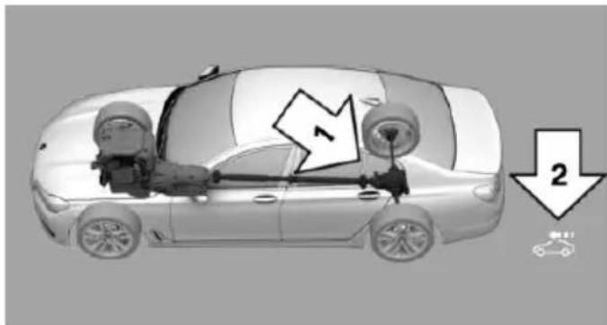
natural_image
Diagram of a car showing front wheel assembly and battery, with no visible text or symbolsColor code blue, arrow 1, and symbol, arrow 2: driving condition Coasting.
Displaying EfficientDynamics info
- "My Vehicle"
- "Technology in action"
- "EfficientDynamics"
Deactivating the system manually
The function can be deactivated individually on the ECO PRO menu.
The setting is stored for the drive profile currently used.
ECO PRO driving style analysis
The concept
In this situation the system helps develop an especially efficient driving style and to conserve fuel.
For this purpose, the driving style is analyzed. The assessment is done in various categories and is displayed on the Control Display.
Using this indication, the individual driving style can be oriented toward conserving fuel.
The current trip is assessed.
The range of the vehicle can be extended by an efficient driving style.
This gain in range is displayed as a bonus range in the instrument cluster and on the Control Display.
Functional requirement
This function is available in ECO PRO mode.
Calling up ECO PRO driving style analysis
- "My Vehicle"
- "Technology in action"
- "Driving style analysis"
Display on the Control Display
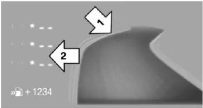
text_image
1 2 » + 1234The display of the ECO PRO driving style analysis consists of a symbolized route and a lookup table.
The road symbolizes the efficiency of the driving style. The more efficient the driving style, the smoother the depicted route becomes, arrow 1.
The table of values contains stars. The more efficient the driving style, the more stars are included in the table and the faster the bonus range increases, arrow 2.
If, on the other hand, the driving style is inefficient, a wavy road and a reduced number of stars is displayed.
To assist with an efficient driving style, ECO PRO tips are displayed during driving.
natural_image
Close-up of a metallic tool tip dispensing liquid into a circular opening, with blurred background elements (no text or symbols visible)Mobility
In order to always ensure your mobility, you will find important information on operating fluids, wheels and tires, maintenance and Roadside Assistance in the following.
Refueling
Vehicle features and options
This chapter describes all standard, country-specific and optional features offered with the series. It also describes features that are not necessarily available in your car, e.g., due to the selected options or country versions. This also applies to safety-related functions and systems. The respectively applicable country provisions must be observed when using the respective features and systems.
Information

CAUTION
With a range of less than 30 miles/50 km it is possible that the engine will no longer have sufficient fuel. Engine functions are no longer ensured. There is risk of property damage. Refuel promptly.
Observe the fuel recommendation, refer to page 252, prior to refueling.
Fuel lid
Opening
- Briefly press the rear edge of the fuel filler flap.
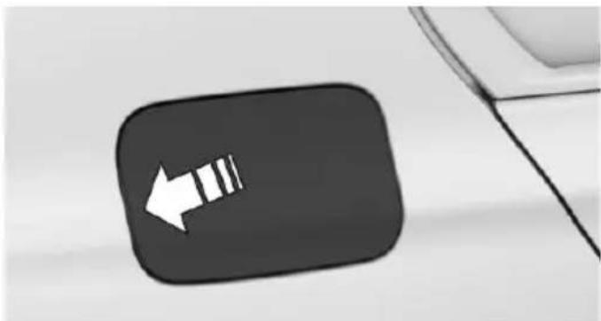
natural_image
Close-up of a black rounded square button with a white left-pointing arrow symbol, next to a curved line (no text or labels visible)- Turn the tank lid counterclockwise.
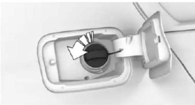
natural_image
Top-down view of an electrical outlet with a circular socket and cable inserted (no text or symbols visible)- Place the tank lid in the bracket attached to the fuel filler flap.
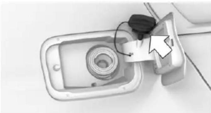
natural_image
Top-down view of a device with a coiled cable and a paper clip, no visible text or symbolsClosing
-
Fit the lid and turn it clockwise until you clearly hear a click.
-
Close the fuel filler flap.

WARNING
The retaining strap of the fuel cap be jammed and crushed during closing. In this case, the lid cannot be correctly closed and fuel vapors or fuel can escape. There is risk of injuries or risk of property damage. Pay attention that the retaining strap is not jammed or crushed when closing the lid.
Manually unlocking fuel filler flap
E. g. in the event of an electrical malfunction.
The release is located in the trunk.
- Remove the cover on the right side trim.
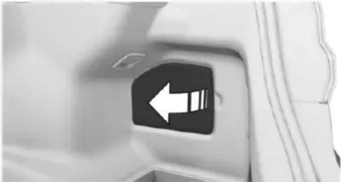
natural_image
Close-up of a car door panel with a white left-pointing arrow icon (no text or symbols)- Pull the green knob with the fuel pump symbol. This releases the fuel filler flap.
Observe the following when refueling

CAUTION
Fuels are toxic and aggressive. Overfilling of the fuel tank can damage the fuel system. On contact with painted surfaces, damage may occur to these surfaces. The environment is polluted. There is risk of property damage. Avoid overfilling.
The fuel tank is full when the filler nozzle clicks off the first time.
Observe safety regulations posted at the gas station.
Fuel
Vehicle features and options
This chapter describes all standard, country-specific and optional features offered with the series. It also describes features that are not necessarily available in your car, e.g., due to the selected options or country versions. This also applies to safety-related functions and systems. The respectively applicable country provisions must be observed when using the respective features and systems.
Fuel recommendation
General information
Depending on the region, many gas stations sell fuel that has been customized to winter or summer conditions. Fuel that is available in winter helps make a cold start easier, e.g.
Information

CAUTION
Even fuels that conform to the specifications can be of low quality. This may cause engine problems, for instance poor engine start-up behavior, poor handling and/or poor performance. There is risk of property damage. In case of engine problems, switch gas stations or use a brand name fuel with a higher octane rating.
Gasoline
For the best fuel efficiency, the gasoline should be sulfur-free or very low in sulfur content.
Fuels that are marked on the gas pump as containing metal must not be used.

CAUTION
Even small amounts of wrong fuel or wrong fuel additives can damage the fuel system and the engine. Furthermore, the catalytic converter is permanently damaged. There is risk of property damage. Do not refuel or add the following in the case of gasoline engines:
▶ Leaded gasoline.
▶ Metallic additives, e.g. manganese or iron.
Do not press the Start/Stop button after refueling the wrong fuel. Contact a dealer's service center or another qualified service center or repair shop.
Fuels with a maximum ethanol content of 25 %, i. e. E10 or E25, may be used for refueling.
Ethanol should satisfy the following quality standards:
US: ASTM 4806-xx
CAN: CGSB-3.511-xx
xx: comply with the current standard in each case.

CAUTION
Wrong fuels can damage the fuel system and the engine. There is risk of property damage. Do not use a fuel with a higher ethanol percentage than recommended or one with other types of alcohol, e.g. M5 to M100.
Recommended fuel grade
BMW recommends AKI 91.
Minimum fuel grade
BMW recommends AKI 89.

CAUTION
Fuel that does not comply with the minimum quality can compromise engine function or cause engine damage. There is risk of prop-
erty damage. Do not fill with fuel that does not comply with the minimum quality.
If you use gasoline with this minimum AKI Rating, the engine may produce knocking sounds when starting at high outside temperatures.
This has no effect on the engine life.

CAUTION
The use of poor-quality fuels may result in harmful engine deposits or damage. Additionally, problems relating to drivability, starting and stalling, especially under certain environmental conditions such as high ambient temperature and high altitude, may occur.
If drivability problems are encountered, we recommend switching to a high quality gasoline brand and a higher octane grade — AKI number — for a few tank fills. To avoid harmful engine deposits, it is highly recommended to purchase gasoline from Top Tier retailers.
Failure to comply with these recommendations may result in the need for unscheduled maintenance.
Wheels and tires
Vehicle features and options
This chapter describes all standard, country-specific and optional features offered with the series. It also describes features that are not necessarily available in your car, e.g., due to the selected options or country versions. This also applies to safety-related functions and systems. The respectively applicable country provisions must be observed when using the respective features and systems.
Tire inflation pressure
Safety information
The tire characteristics and tire inflation pressure influence the following:
The service life of the tires.
Road safety.
▶ Driving comfort.
Checking the tire inflation pressure

WARNING
A tire with low or missing tire inflation pressure impacts handling, such as steering and braking response. There is risk of an accident. Regularly check the tire inflation pressure, and correct it as needed, e.g. twice a month and before a long trip.
Also check the tire inflation pressure of the emergency wheel in the trunk regularly, and correct it as needed.
Tires have a natural, consistent loss of tire inflation pressure.
Tires heat up while driving, and the tire inflation pressure increases along with the tire's temperature. The tire inflation pressure specifications relate to cold tires or tires with the ambient temperature.
Only check the tire inflation pressure when the tires are cold. This means after driving no more than 1.25 miles/2 km or when the vehicle has been parked for at least 2 hours.
The displays of inflation devices may under-read by up to 0.1 bar, 2 psi.
For Flat Tire Monitor: after correcting the tire inflation pressure, reinitialize the Flat Tire Monitor.
For Tire Pressure Monitor: after correcting the tire inflation pressure, reset the Tire Pressure Monitor.
Tire inflation pressure specifications
The tire inflation pressure table, refer to page 255, contains all tire inflation pressure specifications for the specified tire sizes at the ambient temperature. The tire inflation pressure values apply to tire sizes approved by the manufacturer of the vehicle for the vehicle type.
To identify the correct tire inflation pressure, please note the following:
▶ Tire sizes of your vehicle.
▶ Maximum permitted driving speed.
Tire inflation pressures up to 100 mph/160 km/h
For speeds of up to 100 mph/160 km/h and for optimum driving comfort, note the pressure values in the tire inflation pressure table, refer to page 255, and adjust as necessary.
natural_image
Interior view of a car showing the door, seat, and dashboard panel (no text or symbols visible)These pressure values can also be found on the tire inflation pressure label on the driver's door pillar.
Do not exceed a speed of 100 mph/160 km/h.
Tire inflation pressure values up to 100 mph/160 km/h
740Li, 750i xDrive, 750Li xDrive
Tire size Pressure specifications in bar/PSI
Specifications in bar/PSI with cold tires
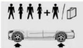
text_image
Diagram showing human silhouette icons and a car with directional arrows, likely illustrating vehicle or transportation concept.245/50 R 18 100 V 2.2 / 32 2.4 / 35 M+S A/S RSC 245/50 R 18 100 H M+S RSC
245/45 R 19 102 V 2.4 / 35 2.6 / 38 M+S XL A/S RSC 245/45 R 19 102 V M+S XL RSC
Front: 245/45 R 19 2.5 / 36 - 98 Y RSC - 2.5 / 36 Rear: 275/40 R 19 101 Y RSC
Front: 245/40 R 20 2.7 / 39 - 99 Y XL RSC - 2.7 / 39 Rear: 275/35 R 20 102 Y XL RSC
Tire size Pressure specifications in bar/PSI
| Front: 245/35 R 21 | 3.0 / 44 | - |
| 96 Y XL RSC | - | 3.0 / 44 |
| Rear: 275/30 R 21 | ||
| 98 Y XL RSC |
| Emergency wheel: | Speed up to a max. of |
| T 135/80 R 18 104 | 50 mph / 80 km/h |
| M | 4.2 / 60 |
Tire inflation pressures at max. speeds above 100 mph/160 km/h

WARNING
In order to drive at maximum speeds in excess of 100 mph/160 km/h, please observe, and, if necessary, adjust tire pressures for speeds exceeding 100 mph/160 km/h from the relevant table on the following pages. Otherwise tire damage and accidents could occur.
Tire inflation pressure values over 100 mph/160 km/h
740Li, 750i xDrive, 750Li xDrive
Without high-speed tuning feature
Tire size Pressure specifications in bar/PSI
Specifications in bar/PSI with cold tires
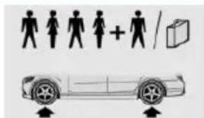
text_image
Diagram showing human silhouette icons and a car with directional arrows indicating movement or orientation.245/50 R 18 100 V 2.5 / 36 2.7 / 39 M+S A/S RSC 245/50 R 18 100 H M+S RSC
245/45 R 19 102 V 2.7 / 39 2.9 / 42 M+S XL A/S RSC 245/45 R 19 102 V M+S XL RSC
| Tire size Pressure specifications in bar/PSI | ||
| Front: 245/45 R 19 | 2.5 / 36 | - |
| 98 Y RSC | - | 2.5 / 36 |
| Rear: 275/40 R 19 | ||
| 101 Y RSC | ||
| Front: 245/40 R 20 | 2.7 / 39 | - |
| 99 Y XL RSC | - | 2.7 / 39 |
| Rear: 275/35 R 20 | ||
| 102 Y XL RSC | ||
| Front: 245/35 R 21 | 3.0 / 44 | - |
| 96 Y XL RSC | - | 3.0 / 44 |
| Rear: 275/30 R 21 | ||
| 98 Y XL RSC | ||
| Emergency wheel: T 135/80 R 18 104 | Speed up to a max. of 50 mph / 80 km/h | |
| M | 4.2 / 60 | |
With high-speed tuning feature
| Tire size Pressure specifications in bar/PSI | |
| Specifications in bar/PSI with cold tires | 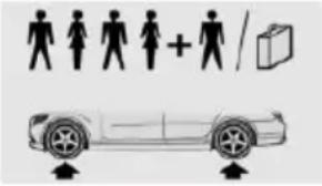 |
| 245/50 R 18 100 H M+S RSC | 2.5 / 36 2.7 / 39 |
| 245/45 R 19 102 V M+S XL RSC | 2.9 /42 3.1 / 45 |
| Front: | 2.7 / 39 - |
| 245/45 R 19 98 Y RSC | - 2.7 / 39 |
| Rear: 275/40 R 19 101 Y RSC | |
| Tire size Pressure specifications in bar/PSI | ||
| Front: | 3.0 / 44 | - |
| 245/40 R 20 99 Y XL RSC | - | 3.0 / 44 |
| Rear: 275/35 R 20 102 Y XL RSC | ||
| Front: | 3.3 / 48 | - |
| 245/35 R 21 96 Y XL RSC | - | 3.3 / 48 |
| Rear: 275/30 R 21 98 Y XL RSC | ||
| Emergency wheel: | Speed up to a max. of 50 mph / 80 km/h | |
| T 135/80 R 18 104 M | 4.2 / 60 | |
Tire identification marks
Tire size
245/45 R 18 96 Y
245: nominal width in mm
45: aspect ratio in %
R: radial tire code
18: rim diameter in inches
96: load rating, not for ZR tires
Y: speed rating, before the R on ZR tires
Speed letter
Q = up to 100 mph, 160 km/h
R = up to 106 mph, 170 km/h
S = up to 112 mph, 180 km/h
T = up to 118 mph, 190 km/h
H = up to 131 mph, 210 km/h
V = up to 150 mph, 240 km/h
W = up to 167 mph, 270 km/h
Y = up to 186 mph, 300 km/h
Tire Identification Number
DOT code: DOT xxxx xxx 0115
xxxx: manufacturer code for the tire brand
xxx: tire size and tire design
0115: tire age
Tires with DOT codes meet the guidelines of the U.S. Department of Transportation.
Tire age
DOT ... 0115: the tire was manufactured in the 1st week of 2015.
Recommendation
Regardless of wear and tear, replace tires at least every 6 years.
Uniform Tire Quality Grading
Quality grades can be found where applicable on the tire sidewall between tread shoulder and maximum section width.
For example: Treadwear 200; Traction AA; Temperature A
DOT Quality Grades
Treadwear
Traction AA A B C
Temperature A B C
All passenger car tires must conform to Federal Safety Requirements in addition to these grades.
Treadwear
The treadwear grade is a comparative rating based on the wear rate of the tire when tested under controlled conditions on a specified government test course. For example, a tire graded 150 would wear one and one-half, 1 g, times as well on the government course as a tire graded 100. The relative performance of tires depends upon the actual conditions of their use, however, and may depart significantly from the norm due to variations in driving habits, service practices and differences in road characteristics and climate.
Traction
The traction grades, from highest to lowest, are AA, A, B, and C.
Those grades represent the tire's ability to stop on wet pavement as measured under controlled conditions on specified government test surfaces of asphalt and concrete. A tire marked C may have poor traction performance.
The traction grade assigned to this tire is based on straight-ahead braking traction tests, and does not include acceleration, cornering, hydroplaning, or peak traction characteristics.
Temperature
The temperature grades are A, the highest, B, and C, representing the tire's resistance to the generation of heat and its ability to dissipate heat when tested under controlled conditions on a specified indoor laboratory test wheel. Sustained high temperature can cause the material of the tire to degenerate and reduce tire life, and excessive temperature can lead to sudden tire failure. The grade C corresponds to a level of performance which all passenger car tires must meet under the Federal Motor Vehicle Safety Standard No. 109. Grades Band A represent higher levels of performance on the laboratory test wheel than the minimum required by law.

WARNING
The temperature grade for this tire is established for a tire that is properly inflated and not overloaded. Excessive speed, underinflation, or excessive loading, either separately or in combination, can cause heat buildup and possible tire failure.
RSC – Run-flat tires
Run-flat tires, refer to page 260, are labeled with a circular symbol containing the letters RSC marked on the sidewall.
M+S
Winter and all-season tires with better cold weather performance than summer tires.
Tire tread
Summer tires
Do not drive with a tire tread depth of less than 0.12 in/3 mm.
There is an increased danger of hydroplaning if the tire tread depth is less than 0.12 in/3 mm.
Winter tires
Do not drive with a tire tread depth of less than 0.16 in/4 mm.
Below a tread depth of 0.16 in/4 mm, tires are less suitable for winter operation.
Minimum tread depth
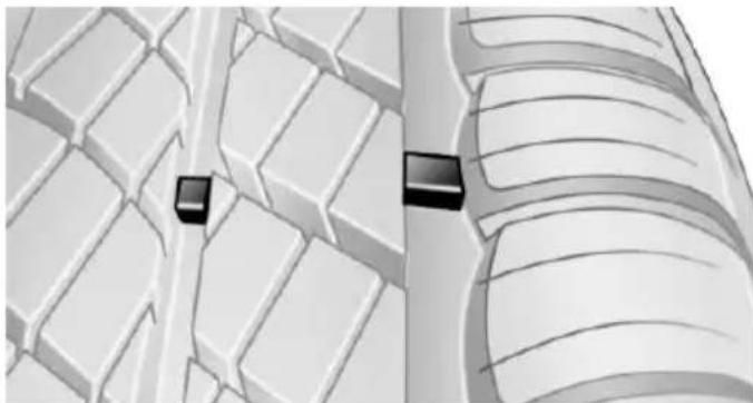
natural_image
Diagram showing two black rectangular blocks placed on a grid-like surface, with no visible text or symbols.Wear indicators are distributed around the tire's circumference and have the legally required minimum height of 0.063 in/1.6 mm.
They are marked on the side of the tire with TWI, Tread Wear Indicator.
Tire damage
General information
Inspect your tires often for damage, foreign objects lodged in the tread, and tread wear.
Information
Driving over rough or damaged road surfaces, as well as debris, curbs and other obstacles can cause serious damage to wheels, tires and suspension parts. This is more likely to occur with low-profile tires, which provide less cushioning between the wheel and the road. Be careful to avoid road hazards and reduce your speed, especially if your vehicle is equipped with low-profile tires.
Indications of tire damage or other vehicle malfunctions:
▶ Unusual vibrations while driving.
▶ Unusual handling such as a strong tendency to pull to the left or right.
Damage can, e. g., be caused by driving over curbs, road damage, or similar things.

WARNING
Damaged tires can lose tire inflation pressure, which can lead to loss of vehicle control. There is risk of an accident. If tire damage is suspected while driving, immediately reduce speed and stop. Have wheels and tires checked. For this purpose, drive carefully to the nearest dealer's service center or another qualified service center or repair shop. Have vehicle towed or transported as needed.

WARNING
Damaged tires can lose tire inflation pressure, which can lead to loss of vehicle control. There is risk of an accident. Do not repair damaged tires, but have them replaced.
Changing wheels and tires
Mounting
Have mounting and wheel balancing carried out by a dealer's service center or another qualified service center or repair shop.
Wheel and tire combination
You can ask the dealer's service center or another qualified service center or repair shop about the right wheel/tire combination and wheel rim versions for the vehicle.
Incorrect wheel and tire combinations impair the function of a variety of systems such as ABS or DSC.
To maintain good handling and vehicle response, use only tires with a single tread configuration from a single manufacturer.
Following tire damage, have the original wheel and tire combination remounted on the vehicle as soon as possible.

WARNING
Wheels and tires which are not suitable for your vehicle can damage parts of the vehicle, e. g. due to contact with the body due to tolerances despite the same official size rating. There is risk of an accident.

WARNING
Mounted steel wheels can cause technical problems, e.g. independent loosening of the lug bolts, damage to the brake discs. There is risk of an accident. Do not mount steel wheels.
Recommended tire brands
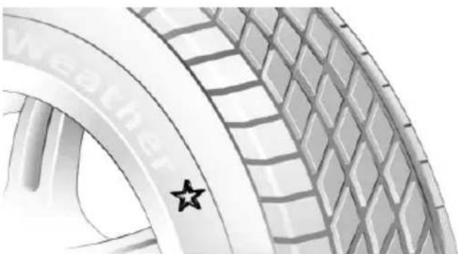
natural_image
Close-up of a car tire with a star marking on the side wheel (no text or symbols visible)For each tire size, the manufacturer of your vehicle recommends certain tire brands. These can be identified by a star on the tire sidewall.
New tires
Tire traction is not optimal due to manufacturing circumstances when tires are brand-new; they achieve their full traction potential after a break-in time.
Drive conservatively for the first 200 miles/300 km.
Retreaded tires
The manufacturer of your vehicle does not recommend the use of retreaded tires.

WARNING
Retreated tires can have different tire casing structures. With advanced age the service life can be limited. There is risk of an accident. Do not use retreated tires.
Winter tires
Winter tires are recommended for operating on winter roads.
Although so-called all-season M+S tires provide better winter traction than summer tires, they do not provide the same level of performance as winter tires.
Maximum speed of winter tires
If the maximum speed of the vehicle is higher than the permissible speed for the winter tires, then a respective symbol is displayed in your field of vision. The plate is available from a dealer's service center or another qualified service center or repair shop.
With mounted winter tires, observe and adhere to the permissible maximum speed.
Run-flat tires
If you are already using run-flat tires, for your own safety you should replace them only with the same kind. No spare tire is available in the case of a flat tire. A dealer's service center or another qualified service center or repair shop will be glad to answer additional questions at any time.
Rotating wheels between axles
Different wear patterns can occur on the front and rear axles depending on individual driving conditions. The tires can be rotated between the axles to achieve even wear. A dealer's service center or another qualified service center or repair shop will be glad to answer additional questions at any time. After rotating, check the tire pressure and correct if needed.
Rotating the tires is not permissible on vehicles with different tire sizes or rim sizes on the front and rear axles.
Storage
Store wheels and tires in a cool, dry place with as little exposure to light as possible.
Always protect tires against all contact with oil, grease and fuels.
Do not exceed the maximum tire inflation pressure indicated on the side wall of the tire.
Run-flat tires
Label
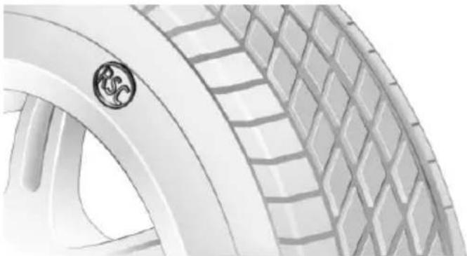
natural_image
Close-up of a white car tire with a logo on the side wheel (no text or symbols visible)RSC label on the tire sidewall.
The wheels consist of tires that are self-supporting, to a limited degree, and possibly special rims.
The support of the sidewall allows the tire to remain drivable to a restricted degree in the event of a tire inflation pressure loss.
Follow the instructions for continued driving with a flat tire.
Changing run-flat tires
For your own safety, only use run-flat tires. No spare tire is available in the case of a flat tire. A dealer's service center or another qualified service center or repair shop will be glad to answer additional questions at any time.
Repairing a flat tire
Safety measures
▶ Park the vehicle as far away as possible from passing traffic and on solid ground.
▶ Switch on the hazard warning system.
▶ Secure the vehicle against rolling away by setting the parking brake.
▶ Turn the steering wheel until the front wheels are in the straight-ahead position and engage the steering wheel lock.
Have all vehicle occupants get out of the vehicle and ensure that they remain outside the immediate area in a safe place, such as behind a guardrail.
▶ If necessary, set up a warning triangle at an appropriate distance.
Mobility System
The concept
With the Mobility System, minor tire damage can be sealed quickly to enable continued travel. To accomplish this, sealant is pumped into the tires, which seals the damage from the inside.
The compressor can be used to check the tire inflation pressure.
Information
▶ Follow the instructions on using the Mobility System found on the compressor and sealant container.
▶ Use of the Mobility System may be ineffective if the tire puncture measures approx. 1/8 in/4 mm or more.
Contact a dealer's service center or another qualified service center or repair shop if the tire cannot be made drivable.
▶ If possible, do not remove foreign bodies that have penetrated the tire.
▶ Pull the speed limit sticker off the sealant container and apply it to the steering wheel.
The use of a sealant can damage the TPM wheel electronics. In this case, have the electronics checked at the next opportunity and have them replaced if needed.
Storage
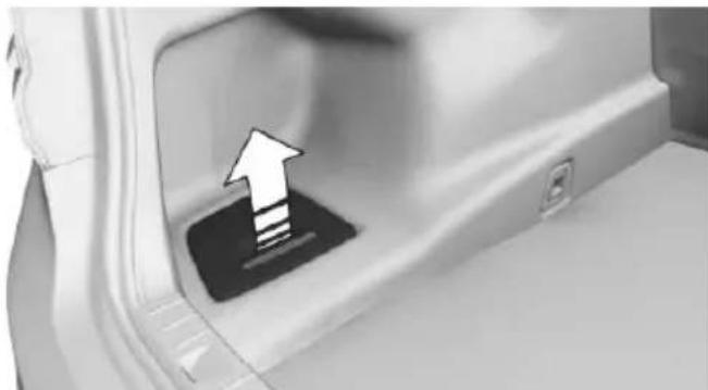
natural_image
Close-up of a car door panel with an upward arrow pointing to the interior (no text or symbols visible)The mobility system is in the left storage compartment of the cargo area.
Sealant container
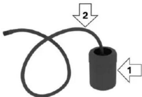
text_image
2 1▶ Sealant container, arrow 1.
▶ Filling hose, arrow 2.
Observe use-by date on the sealant container.
Compressor
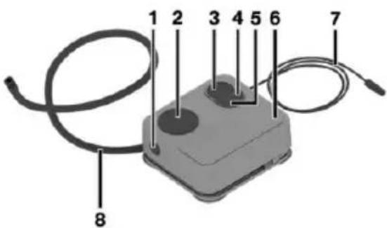
text_image
1 2 3 4 5 6 7 81 Bottle unlocking
2 Holder for bottle
3 Inflation pressure dial
4 Reduce inflation pressure
5 On/off switch
6 Compressor
7 Connector/cable for socket
8 Connection hose
Filling the tire with sealant
- Shake the sealant container.
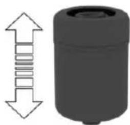
natural_image
3D rendered mechanical component with a vertical double-headed arrow indicating upward compression (no text or symbols)- Pull filling hose completely out of the cover of the sealant container. Do not kink the hose.
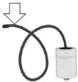
natural_image
Simple diagram of a cable with a connector and arrow indicating direction (no text or symbols)- Slide the sealing container into the holder on the compressor housing, ensuring that it engages audibly.
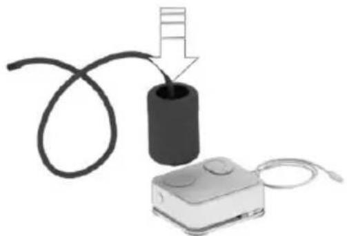
natural_image
Illustration of a battery connected to a device with a cable, showing a step indicator (no text or symbols present)- Screw the filling hose of the sealant container onto the tire valve of the nonworking wheel.
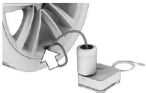
natural_image
Close-up of a car wheel connected to a cylindrical device with cable, no visible text or symbols- With the compressor switched off, insert the plug into the power socket inside the vehicle.
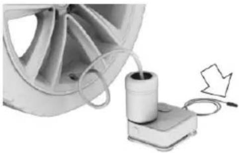
natural_image
Close-up of a car wheel and a cylindrical device with a cable, next to a small arrow symbol (no text or labels visible)- With operating readiness switched on or the engine running, switch on the compressor.
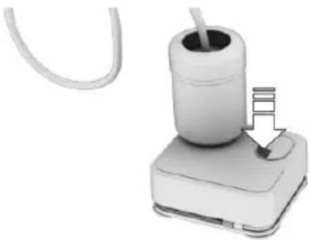
natural_image
Close-up of a white cylindrical device with a cable inserted, showing a small inset image of its cable (no text or symbols visible)DANGER If the exha
If the exhaust pipe is blocked or ventilation is insufficient, harmful exhaust gases can enter into the vehicle. The exhaust gases contain carbon monoxide, an odorless and colorless but highly toxic gas. In enclosed areas, exhaust gases can also accumulate outside of the vehicle. There is danger to life. Keep the exhaust pipe free and ensure sufficient ventilation.
CAUTION The comp
The compressor can overheat during extended operation. There is risk of property damage. Do not run the compressor for more than 10 min.
Let the compressor run for max. 10 minutes to fill the tire with sealant and achieve a tire inflation pressure of approx. 2.5 bar.
While the tire is being filled with sealant, the tire inflation pressure may sporadically reach approx. 5 bar. Do not switch off the compressor at this point.
If a tire inflation pressure of 2 bar is not reached:
- Switch off the compressor.
- Unscrew the filling hose from the wheel.
- Drive 33 ft/10 m forward and back to distribute the sealant in the tire.
- Inflate the tire again using the compressor.
If a tire inflation pressure of 2 bar cannot be reached, contact your dealer's service center or another qualified service center or repair shop.
Stowing the Mobility System
- Unscrew the filling hose of the sealant container from the wheel.
- After pressing the red unlock button on the compressor, remove the sealing container.
- Wrap the empty sealant container in suitable material to avoid dirtying the trunk.
- Stow the Mobility System back in the vehicle.
Distributing the sealant
Immediately drive approx. 5 miles/10 km to ensure that the sealant is evenly distributed in the tire.
Do not exceed a speed of 50 mph/80 km/h.
If possible, do not drive at speeds less than 12 mph/20 km/h.
To correct the tire inflation pressure
- Stop at a suitable location.
- Screw the connection hose of the compressor directly onto the tire valve stem.
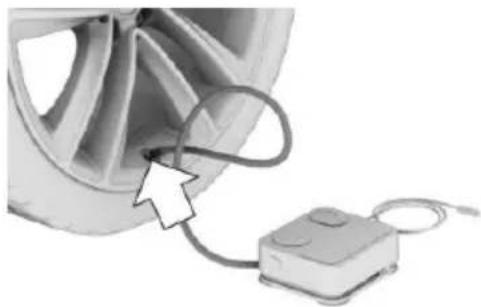
natural_image
Close-up of a car wheel connected to a small electronic device (no visible text or symbols)- Insert the connector into the power socket inside the vehicle.
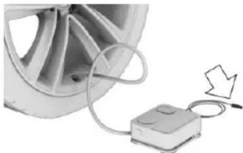
natural_image
Close-up of a car wheel connected to a small electronic device with a cable, showing a downward arrow (no text or symbols visible)- Correct the tire inflation pressure to at least 2.0 bar.
▶ Increase pressure: with operating readiness switched on or the engine running, switch on the compressor.
To reduce the pressure: press the button on the compressor.
Continuing the trip
Do not exceed the maximum permissible speed of 50 mph/80 km/h.
Reinitialize the Tire Pressure Monitor.
Replace the nonworking tire and the sealant container of the Mobility System as soon as possible.
Snow chains
Fine-link snow chains
The manufacturer of your vehicle recommends use of fine-link snow chains. Certain types of fine-link snow chains have been tested by the manufacturer of the vehicle and recommended as road-safe and suitable.
Information regarding suitable snow chains is available from a dealer's service center or another qualified service center or repair shop.
Use
Use only in pairs on the rear wheels, equipped with the tires of the following size:
245/50 R 18.
245/45 R 19.
Follow the snow chain manufacturer's instructions.
Make sure that the snow chains are always sufficiently tight. Retighten as needed according to the chain manufacturer's instructions.
Do not initialize the Flat Tire Monitor after mounting snow chains, as doing so may result in incorrect readings.
Do not initialize the Tire Pressure Monitor after mounting snow chains, as doing so may result in incorrect readings.
When driving with snow chains, briefly activate Dynamic Traction Control if needed.
Maximum speed with snow chains
Do not exceed a speed of 30 mph/50 km/h when using snow chains.
Rear wheel steering during operation with snow chains
General information
In order to guarantee free running of the wheels when operating with snow chains, the rear wheel steering of the integral active steering must be switched off when snow chains
are mounted. For this, it is possible to confirm via iDrive that snow chains are mounted.
Information

WARNING
When rear wheel steering is switched on and snow chains are mounted, there can be contact between snow chains and the chassis. There is risk of accidents or risk of property damage. With mounted snow chains, switch off the rear wheel steering.
Switching off rear wheel steering
With the setting that snow chains are mounted, the rear wheel steering is switched off.
About iDrive:
- "My Vehicle"
- "Vehicle settings"
- "Tire chains"
- "Tire chains installed"
Starting with the permissible maximum speed with snow chains of 30 mph/50 km/h the rear wheel steering will be switched on automatically.
Tire Pressure Monitor TPM
The concept
The system monitors tire inflation pressure in the four mounted tires. The system warns you if there is a loss of pressure in one or more tires. For this purpose, sensors in the tire valves measure the tire inflation pressure and tire temperature.
Information
With use of the system observe further information found under Tire inflation pressure, refer to page 254.
Functional requirements
The system must have been reset with the correct tire inflation pressure; otherwise, reliable signaling of tire inflation pressure loss is not assured.
Reset the system after each adjustment of the tire inflation pressure and after every tire or wheel change.
Always use wheels with TPM electronics to ensure that the system will operate properly.
Status display
The current status of the Tire Pressure Monitor TPM can be displayed, e.g., whether or not the TPM is active.
About iDrive:
- "My Vehicle"
- "Vehicle status"
- "Tre Pressure Monitor"
The status is displayed.
Status control display
Tire and system status are indicated by the color of the wheels and a text message on the Control Display.
All wheels green
System is active and will issue a warning relative to the tire inflation pressures stored during the last reset.
One to four wheels, yellow
A flat tire or major drop in tire inflation pressure in the indicated tires.
Wheels, gray
The system cannot detect a flat tire. Reasons for this may be:
The system is being reset.
Malfunction.
Status information
The status control display additionally shows the current tire inflation pressures and, depending on the model, tire temperatures. It shows the actual values read; they may vary depending on driving style or weather conditions.
Carry out reset
Reset the system after each adjustment of the tire inflation pressure and after every tire or wheel change.
Via iDrive and in the vehicle:
- "My Vehicle"
- "Vehicle status"
- Tire Pressure Monitor reset
- Start the engine - do not drive off.
- Reset tire inflation pressure: "Perform reset".
- Drive away.
The wheels are displayed in gray and the status "Resetting Tire Pressure Monitor..." is displayed.
After driving faster than 19 mph/30 km/h for a short period, the set tire inflation pressures are accepted as reference values. The reset is completed automatically while driving.
After a successfully completed Reset, the wheels on the Control Display are shown in green and "Tire Pressure Monitor active. For recommended pressures, see tire pressure label." is displayed.
You may interrupt this trip at any time. When you continue the reset resumes automatically.
Messages
Required tire inflation pressure check message

A Check Control message is displayed.
The system has detected a wheel change, but no reset was done.
No reset was performed for the system. The system therefore issues a warning based on the tire inflation pressures before the last reset.
▶ Inflation was not carried out according to specifications.
The tire inflation pressure has fallen below the level of the last reset.
In these cases:
- Check the tire pressure and correct as needed.
- Reset the system.
Message in case of low tire pressure

The yellow warning lamp lights up.

A Check Control message is displayed.
There is a tire inflation pressure loss.
No reset was performed for the system. The system therefore issues a warning based on the tire inflation pressures before the last reset.
In these cases:
- Reduce your speed and drive moderately. Do not exceed a speed of 80 mph/130 km/h.
- At the next opportunity, e.g. gas station, check and if necessary correct the tire inflation pressure in all four tires.
- Reset the system.
Message in case of sharp tire inflation pressure loss

The yellow warning lamp lights up.
A symbol with the affected tires will be displayed in the Check Control message.
There is a flat tire or a major loss in tire inflation pressure.
No reset was performed for the system. The system therefore issues a warning based on the tire inflation pressures before the last reset.
In these cases:
- Reduce your speed and stop cautiously. Avoid sudden braking and steering maneuvers.
- Check whether the vehicle is fitted with normal tires or run-flat tires.
Run-flat tires, refer to page 260, are la-beled with a circular symbol containing the letters RSC marked on the tire's sidewall.

WARNING
A damaged regular tire with low or missing tire inflation pressure impacts handling, such as steering and braking response. Run-flat tires can maintain limited stability. There is risk of an accident. Do not continue driving if the vehicle is not equipped with run-flat tires. Observe the information on run-flat tires and continued driving with these tires.
A low tire inflation pressure might turn on DSC Dynamic Stability Control.
Actions in the event of a flat tire
Normal tires
- Identify the damaged tire.
Do this by checking the air pressure in all four tires.
The tire pressure gauge of the Mobility System, refer to page 260, can be used for this purpose.
If the tire inflation pressure in all four tires is shown to be correct, it is possible that the Tire Pressure Monitor did not perform a reset. Then perform the reset.
If identification of flat tire damage is not possible, please contact a dealer's service center or another qualified service center or repair shop.
- Fixing a flat tire, where applicable with the Mobility System.
- Replacing a damaged tire, where applicable with the emergency wheel.
Use of sealant, e.g., the Mobility System, may damage the TPM wheel electronics. In this case, have the electronics checked at the next opportunity and have them replaced if needed.
Run-flat tires
Maximum speed
You may continue driving with a damaged tire at speeds up to 50 mph/80 km/h.
Continued driving with a flat tire
If continuing to drive with a damaged tire:
- Avoid sudden braking and steering maneuvers.
- Do not exceed a speed of 50 mph/80 km/h.
- Check the air pressure in all four tires at the next opportunity.
If the tire inflation pressure in all four tires is shown to be correct, it is possible that the Tire Pressure Monitor did not perform a reset. In that case, carry out a reset.
Possible driving distance with complete loss of tire inflation pressure:
The possible driving distance after a loss of tire inflation pressure depends on cargo load, driving style and road conditions.
A vehicle with an average load has a possible driving range of approx. 50 miles/80 km.
A vehicle with a damaged tire reacts differently, e.g., it has reduced lane stability during braking, a longer braking distance and different self-steering properties. Adjust your driving style accordingly. Avoid abrupt steering ma-
neuvers or driving over obstacles, e.g., curbs, potholes, etc.
Because the possible driving distance depends on how the vehicle is used during the trip, the actual distance may be shorter or longer depending on the driving speed, road conditions, external temperature, cargo load, etc.

WARNING
Your vehicle handles differently when a run-flat tire is damaged and has low or missing tire inflation pressure, e.g., your lane stability is reduced when braking, braking distances are longer and the self-steering properties will change. There is risk of an accident.
Drive moderately and do not exceed a speed of 50 mph/80 km/h.
System limits
The system does not function properly if a reset has not been carried out, e.g., a flat tire is reported though tire inflation pressures are correct.
The tire inflation pressure depends on the tire's temperature. Driving or exposure to the sun will increase the tire's temperature, thus increasing the tire inflation pressure. The tire inflation pressure is reduced when the tire temperature falls again. These circumstances may cause a warning when temperatures fall very sharply.
The system cannot indicate sudden serious tire damage caused by external circumstances.
Malfunction

The yellow warning lamp flashes and then lights up continuously. A Check Control message is displayed. No flat tire or loss of tire inflation pressure can be detected.
Examples and recommendations in the following situations:
▶ A wheel without TPM electronics is mounted, e.g. emergency wheel: Have it
checked by a dealer's service center or another qualified service center or repair shop as needed.
Malfunction: Have system checked by a dealer's service center or another qualified service center or repair shop.
▷ TPM was unable to complete the reset. Reset the system again.
▶ Interference through systems or devices with the same radio frequency: After leaving the area of the interference, the system automatically becomes active again.
Declaration according to NHTSA/FMVSS 138 Tire Pressure Monitoring System
Each tire, including the spare (if provided) should be checked monthly when cold and inflated to the inflation pressure recommended by the vehicle manufacturer on the vehicle placard or tire inflation pressure label. (If your vehicle has tires of a different size than the size indicated on the vehicle placard or tire inflation pressure label, you should determine the proper tire inflation pressure for those tires.) As an added safety feature, your vehicle has been equipped with a tire pressure monitoring system (TPMS) that illuminates a low tire pressure telltale when one or more of your tires is significantly under-inflated. Accordingly, when the low tire pressure telltale illuminates, you should stop and check your tires as soon as possible, and inflate them to the proper pressure. Driving on a significantly under-inflated tire causes the tire to overheat and can lead to tire failure. Under-inflation also reduces fuel efficiency and tire tread life, and may affect the vehicle's handling and stopping ability. Please note that the TPMS is not a substitute for proper tire maintenance, and it is the driver's responsibility to maintain correct tire pressure, even if under-inflation has not reached the level to trigger illumination of the TPMS low tire pressure telltale. Your vehicle has also been equipped with a TPMS malfunction indicator to indicate when the system is not operating properly. The TPMS malfunction indicator is combined with the low tire pressure telltale. When the system detects a malfunction, the telltale will flash for approximately one minute and then remain continuously illuminated. This sequence will continue upon subsequent vehicle start-ups as long as the malfunction exists. When the malfunction indicator is illuminated, the system may not be able to detect or signal low tire pressure as intended. TPMS malfunctions may occur for a variety of reasons, including the installation of replacement or alternate tires or wheels on the vehicle that prevent the TPMS from functioning properly. Always check the TPMS malfunction telltale after replacing one or more tires or wheels on your vehicle to ensure that the replacement or alternate tires and wheels allow the TPMS to continue to function properly.
FTM Flat Tire Monitor
The concept
The system detects tire inflation pressure loss on the basis of rotation speed differences between the individual wheels while driving.
In the event of a tire inflation pressure loss, the diameter and therefore the rotational speed of the corresponding wheel changes. This will be detected and reported as a flat tire.
The system does not measure the actual inflation pressure in the tires.
Functional requirements
The system must have been initialized when the tire inflation pressure was correct; otherwise, reliable flagging of a flat tire is not assured. Initialize the system after each correction of the tire inflation pressure and after every tire or wheel change.
Status display
The current status of the flat tire monitor can be displayed, e.g., whether the RPA is active.
About iDrive:
- "My Vehicle"
- "Vehicle status"
- "E" at Tire Monitor"
The status is displayed.
Initialization
When initializing the once set inflation tire pressures serve as reference values in order to detect a flat tire. Initialization is started by confirming the tire inflation pressures.
Do not initialize the system when driving with snow chains.
About iDrive:
- "My Vehicle"
- "Vehicle status"
- Flat Tire Monitor reset
- Start the engine - do not drive off.
- Start the initialization: "Perform reset"
- Drive away.
The initialization is completed while driving, which can be interrupted at any time.
The initialization automatically continues when driving resumes.
Indication of a flat tire

The yellow warning lamp lights up. A Check Control message is displayed.
There is a flat tire or a major loss in tire inflation pressure.
- Reduce your speed and stop cautiously. Avoid sudden braking and steering maneuvers.
- Check whether the vehicle is fitted with normal tires or run-flat tires.
Run-flat tires, refer to page 260, are labeled with a circular symbol containing the letters RSC marked on the tire's sidewall.

WARNING
A damaged regular tire with low or missing tire inflation pressure impacts handling, such as steering and braking response. Run-flat tires can maintain limited stability. There is risk of an accident. Do not continue driving if the vehicle is not equipped with run-flat tires. Observe the information on run-flat tires and continued driving with these tires.
When a flat tire is indicated, DSC Dynamic Stability Control is switched on if needed.
System limits
A natural, even tire inflation pressure loss in all four tires will not be recognized. Therefore, check the tire inflation pressure regularly.
Sudden serious tire damage caused by external circumstances cannot be recognized in advance.
The system could be delayed or malfunction in the following situations:
▶ When the system has not been initialized.
When driving on a snowy or slippery road surface.
▶ Sporty driving style: spinning traction wheels, high lateral acceleration (drifting).
▶ When driving with snow chains.
Actions in the event of a flat tire
Normal tires
- Identify the damaged tire.
Do this by checking the air pressure in all four tires.
The tire pressure gauge of the Mobility System, refer to page 260, can be used for this purpose.
If the tire inflation pressure in all four tires is correct, the Flat Tire Monitor may not
have been initialized. In this case, initialize the system.
If identification of flat tire damage is not possible, please contact a dealer's service center or another qualified service center or repair shop.
- Fix the flat tire using the Mobility System, refer to page 260.
Run-flat tires
Maximum speed
You may continue driving with a damaged tire at speeds up to 50 mph/80 km/h.
Continued driving with a flat tire
If continuing to drive with a damaged tire:
- Avoid sudden braking and steering maneuvers.
- Do not exceed a speed of 50 mph/80 km/h.
- Check the air pressure in all four tires at the next opportunity.
If the tire inflation pressure in all four tires is correct, the Flat Tire Monitor may not have been initialized. In this case, initialize the system.
Possible driving distance with complete loss of tire inflation pressure:
The possible driving distance after a loss of tire inflation pressure depends on cargo load, driving style and road conditions.
A vehicle with an average load has a possible driving range of approx. 50 miles/80 km.
A vehicle with a damaged tire reacts differently, e.g., it has reduced lane stability during braking, a longer braking distance and different self-steering properties. Adjust your driving style accordingly. Avoid abrupt steering maneuvers or driving over obstacles, e.g., curbs, potholes, etc.
Because the possible driving distance depends on how the vehicle is used during the trip, the actual distance may be shorter or longer depending on the driving speed, road conditions, external temperature, cargo load, etc.
WARNING Your vehicle
Your vehicle handles differently when a run-flat tire is damaged and has low or missing tire inflation pressure, e.g., your lane stability is reduced when braking, braking distances are longer and the self-steering properties will change. There is risk of an accident.
Drive moderately and do not exceed a speed of 50 mph/80 km/h.
Final tire failure
Vibrations or loud noises while driving can indicate the final failure of a tire.
Reduce speed and stop; otherwise, pieces of the tire could come loose and cause an accident.
Do not continue driving. Contact a dealer's service center or another qualified service center or repair shop.
Engine compartment
Vehicle features and options
This chapter describes all standard, country-specific and optional features offered with the series. It also describes features that are not necessarily available in your car, e. g., due to
the selected options or country versions. This also applies to safety-related functions and systems. The respectively applicable country provisions must be observed when using the respective features and systems.
Important features in the engine comp.
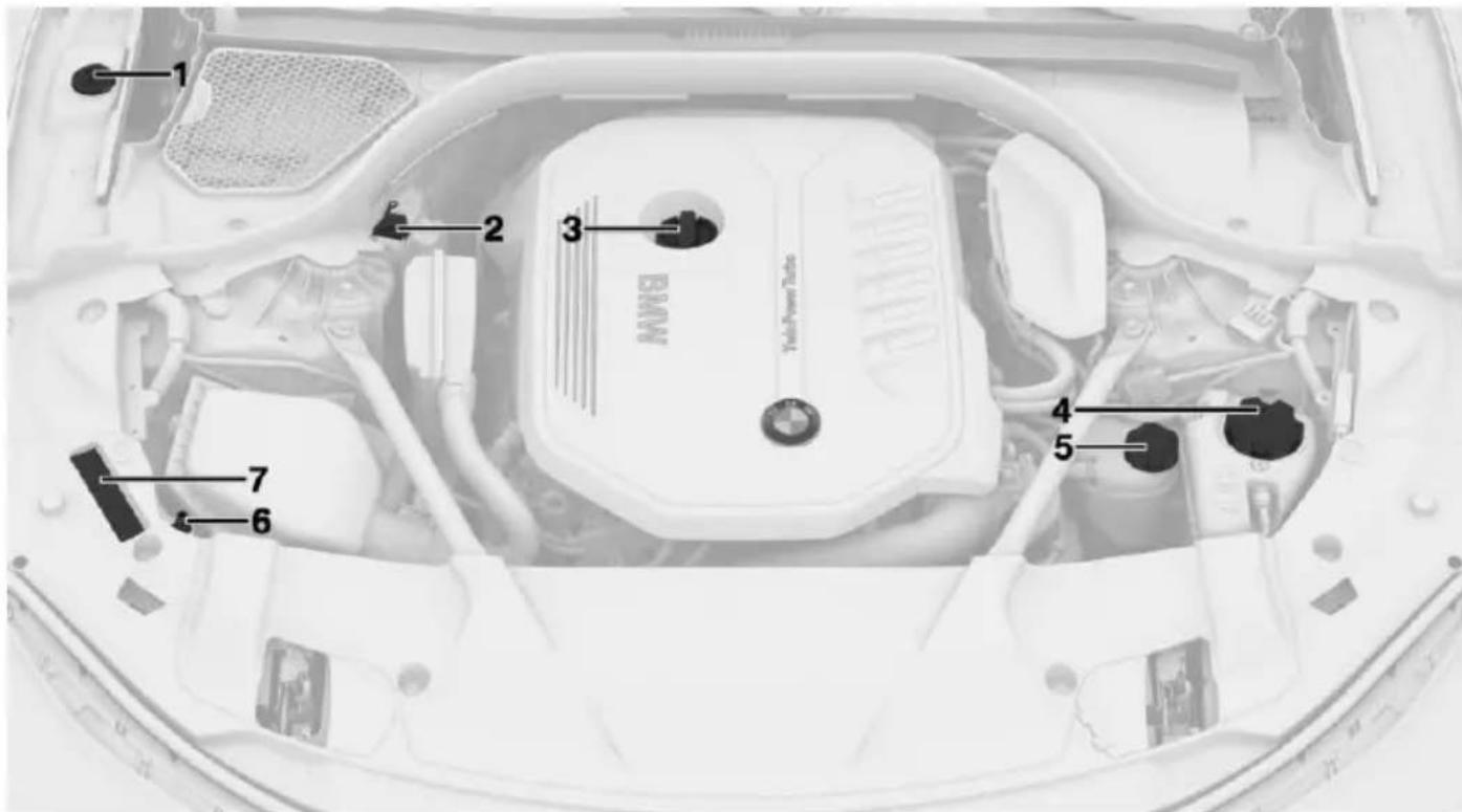
text_image
1 2 3 BMW Taylor Power Tube 4 5 6 71 Washer fluid reservoir
2 Jump-starting, positive battery terminal
3 Oil filler neck
4 Coolant reservoir, engine
5 Gasoline engine only: coolant reservoir, air conditioning
6 Jump-starting, negative battery terminal
7 Vehicle identification number
Hood
Information

WARNING
Improperly executed work in the engine compartment can damage components and lead to a safety risk. There is risk of accidents or risk of property damage.

WARNING
The engine compartment accommodates moving components. Certain components can move in the engine compartment with the vehicle switched off, e.g. the cooler fan. There is risk of injuries. Do not reach into the area of moving parts. Keep articles of clothing and hair away from moving parts.

CAUTION
Folded-away wipers can be jammed when the hood is opened. There is risk of property damage. Make sure that the wipers with the wiper blades mounted are folded down onto the windshield before opening the hood.

WARNING
There are protruding parts, e.g. lock hook, on the inside of the hood. There is risk of injuries. If the hood is open, pay attention to protruding parts and keep these areas clear.

WARNING
An incorrectly locked hood can open while driving and restrict visibility. There is risk of an accident. Stop immediately and correctly close the hood.

WARNING
Body parts can be jammed on opening and closing the hood. There is risk of injuries. Make sure that the area of movement of the hood is clear during opening and closing.
Opening the hood
- Pull lever, arrow 1. Hood is unlocked.
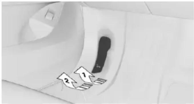
text_image
Medical or medical device component with numbered arrows and a warning symbol, likely indicating surgical or diagnostic features.-
After the lever is released, pull the lever again, arrow 2. Hood can be opened.
-
Be careful of protruding parts on the hood.
Closing the hood
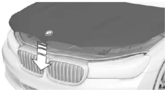
natural_image
Close-up of a car's front grille and hood, showing grille grating and a logo (no text or symbols visible)Let the hood drop from a height of approx. 16 in/40 cm and push down on it to lock it fully. The hood must audibly engage on both sides.
Engine oil
Vehicle features and options
This chapter describes all standard, country-specific and optional features offered with the series. It also describes features that are not necessarily available in your car, e.g., due to the selected options or country versions. This also applies to safety-related functions and systems. The respectively applicable country provisions must be observed when using the respective features and systems.
General information
The engine oil consumption is dependent on the driving style and driving conditions.
The engine oil consumption can increase in the following situations, for example:
▶ Sporty driving style.
▶ Break-in of the engine.
▶ Idling of the engine.
▶ With use of engine oil types that are not approved.
Therefore, regularly check the engine oil level after refueling.
The vehicle is equipped with electronic oil measurement.
The electronic oil measurement has two measuring principles:
▶ Status display
▶ Detailed measurement
Electronic oil measurement
Status display
The concept
The engine oil level is monitored electronically while driving and shown on the Control Display.
If the engine oil level reaches the minimum level, a check control message is displayed.
Requirements
A current measured value is available after approx. 30 minutes of driving. During a shorter trip, the status of the last, sufficiently long trip is displayed.
With frequent short-distance trips, regularly perform a detailed measurement.
Displaying the engine oil level
About iDrive:
- "My Vehicle"
- "Vehicle status"
- "Engine oil level"
- "Measure engine oil level"
The engine oil level is displayed.
Engine oil level display messages
Different messages appear on the Control Display depending on the engine oil level. Pay attention to these messages.
If the engine oil level is too low within the next 125 miles/200 km, add engine oil, refer to page 274.

CAUTION
A too low engine oil level causes engine damage. There is risk of property damage. Immediately add engine oil.
Take care not to add too much engine oil.

CAUTION
Too much engine oil can damage the engine or the catalytic converter. There is risk of property damage. Do not add too much engine oil. Have too much engine oil siphoned off by a dealer's service center or another qualified service center or repair shop.
Detailed measurement
The concept
In the detailed measurement the engine oil level is checked and displayed via a scale.
Gasoline engine:
If the engine oil level reaches the minimum level, a check control message is displayed.
Diesel engine:
During the measurement, the idle speed is increased somewhat.
General information
A detailed measurement is only possible with certain engines.
Requirements
▶ Vehicle is on level road.
▶ Selector lever in selector lever position N or P and accelerator pedal not depressed.
▶ Engine is running and is at operating temperature.
Performing a detailed measurement
About iDrive:
- "My Vehicle"
- "Vehicle status"
- "Measure engine oil level"
- "Start measurement"
The engine oil level is checked and displayed via a scale.
Time: approx. 1 minute.
Adding engine oil
Information

CAUTION
A too low engine oil level causes engine ge. There is risk of property damage.
Add engine oil within the next
125 miles/200 km.

CAUTION
Too much engine oil can damage the engine or the catalytic converter. There is risk of property damage. Do not add too much engine oil. Have too much engine oil siphoned off by a dealer's service center or another qualified service center or repair shop.

WARNING
Operating materials, e.g. oils, greases, coolants, fuels, can contain harmful ingredients. There is risk of injuries or danger to life. Observe the instructions on the containers. Avoid the contact of articles of clothing, skin or eyes with operating materials. Do not refill operating materials into different bottles. Store operating materials out of reach of children.
General information
Establish idle state and safely park the vehicle before engine oil is added.
Overview
The oil filler neck is located in the engine compartment, refer to page 271.
Opening the oil filler neck
Only add engine oil when the message is displayed in the instrument cluster. The quantity to be added is indicated in the message displayed in the instrument cluster.
-
Opening the hood, refer to page 272
-
Turn the oil filler neck counter-clockwise, arrow.
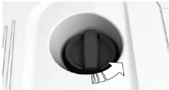
natural_image
Close-up of a mechanical component with a circular opening and internal slot, showing no visible text or symbols.- Add motor oil.
Engine oil types to add
Information

CAUTION
Oil additives can damage the engine.
There is risk of property damage. Do not use oil additives.

CAUTION
Incorrect engine oil can cause malfunctions in the engine or damage it. There is risk of property damage. When selecting an engine oil, make sure that the engine oil has the correct viscosity grade.
The engine oil quality is critical for the life of the engine.
Viscosity grades
When selecting an engine oil, ensure that the engine oil belongs to one of the viscosity grades SAE 0W-40, SAE 0W-30, SAE 5W-40, SAE 5W-30, 0W-20 or 5W-20.
The viscosity grades 0W-20 and 5W-20 are only suitable for particular engines.
Suitable engine oil types
Add engine oils that meet the following oil rating standards:
Gasoline engine
BMW Longlife-01.
BMW Longlife-01 FE.
BMW Longlife-14 FE+.
The oil rating BMW Longlife-14 FE+ is only suitable for particular gasoline motors.
More information about suitable engine oil ratings and viscosities of engine oils can be requested from a dealer's service center or another qualified service center or repair shop.
Alternative engine oil types
If an engine oil suitable for continuous use is not available, up to 1 US quart/liter of an engine oil with the following oil rating can be added:
Gasoline engine
API SL or superior oil rating.
Engine oil change

CAUTION
Engine oil that is not changed in timely fashion can cause increased engine wear and thus engine damage. There is risk of property damage. Do not exceed the service data indicated in the vehicle.
The vehicle manufacturer recommends that you let the dealer's service center or another qualified service center or repair shop change the motor oil.
BMW recommends
Original BMW Engine Oil.
Coolant
Vehicle features and options
This chapter describes all standard, country-specific and optional features offered with the series. It also describes features that are not necessarily available in your car, e.g., due to the selected options or country versions. This also applies to safety-related functions and systems. The respectively applicable country provisions must be observed when using the respective features and systems.
Information

WARNING
With the engine hot and the cooling system open, coolant can escape and lead to burns. There is risk of injuries. Only open the cooling system with the engine cooled down.

WARNING
Additives are harmful and incorrect additives can damage the engine. There is risk of injuries and risk of property damage. Avoid the contact of articles of clothing, skin or eyes with additives. Do not swallow any additives. Use suitable additives only.
Coolant consists of water and additives.
Not all commercially available additives are suitable for the vehicle. Information about suitable additives is available from a dealer's service center or another qualified service center or repair shop.
Coolant level
General information
Vehicles with gasoline engine feature two cooling circuits. Always check the coolant levels of both coolant reservoirs and refill as needed.
The coolant level is indicted using minimum and maximum markings. Depending on the coolant reservoir, the minimum and maximum markings are located at different locations.
Overview
Opening the hood, refer to page 272
Depending on the engine installation, the coolant reservoir is located on the right side or the left side of the engine compartment, refer to page 271.
Checking the coolant level in the filler neck
- Let the engine cool.
- Turn the lid of the coolant reservoir slightly counterclockwise to allow any excess pressure to dissipate, then open it.
- Open the coolant reservoir lid.
- The coolant level is correct if it lies between the minimum and maximum marks in the filler neck.
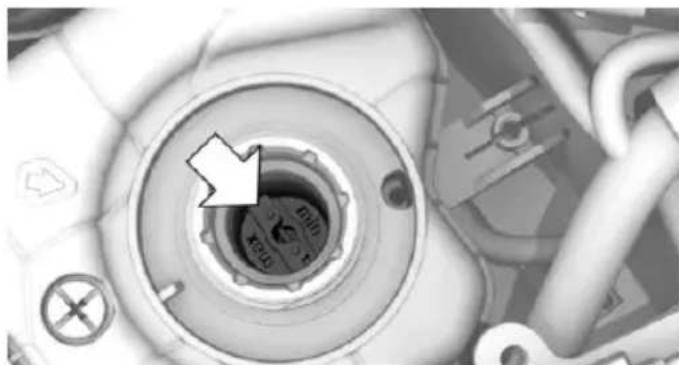
natural_image
Close-up of a mechanical component with a circular dial and arrow indicator (no readable text or symbols)Adding
- Let the engine cool.
-
Turn the lid of the coolant reservoir slightly counterclockwise to allow any excess pressure to dissipate, then open it.
-
If the coolant is low, slowly add coolant up to the specified level; do not overfill.
- Turn the lid until there is an audible click. The arrows on the coolant reservoir and the lid must point towards one another.
- Have the cause of the coolant loss eliminated as soon as possible.
Disposal

Comply with the relevant environmental protection regulations when disposing of coolant and coolant additives.
Maintenance
Vehicle features and options
This chapter describes all standard, country-specific and optional features offered with the series. It also describes features that are not necessarily available in your car, e.g., due to the selected options or country versions. This also applies to safety-related functions and systems. The respectively applicable country provisions must be observed when using the respective features and systems.
BMW maintenance system
The maintenance system indicates required maintenance measures, and thereby provides support in maintaining road safety and the operational reliability of the vehicle.
In some cases scopes and intervals may vary according to the country-specific version. Replacement work, spare parts, fuels and lubricants and wear materials are calculated separately. Further information is available from a dealer's service center or another qualified service center or repair shop.
Condition Based Service CBS
Sensors and special algorithms take into account the driving conditions of your vehicle. Based on this, Condition Based Service recognizes the maintenance requirements.
The system makes it possible to adapt the amount of maintenance corresponding to your user profile.
Detailed information on service requirements, refer to page 119, can be displayed on the Control Display.
Service data in the remote control
Information on the required maintenance is continuously stored in the remote control. The dealer's service center can read this data out and suggest an optimized maintenance scope for your vehicle.
Therefore, hand the service advisor the remote control with which the vehicle was driven most recently.
Storage periods
Storage periods during which the vehicle battery was disconnected are not taken into account.
If this occurs, have a dealer's service center or another qualified service center or repair shop update the time-dependent maintenance procedures, such as checking brake fluid and, if necessary, changing the engine oil and the microfilter/activated-charcoal filter.
Service and Warranty Information Booklet for US models and Warranty and Service Guide Booklet for Canadian models
Please consult your Service and Warranty Information Booklet for US models and Warranty and Service Guide Booklet for Canadian models for additional information on service requirements.
The manufacturer of your vehicle recommends that maintenance and repair be performed by a dealer's service center or another qualified service center or repair shop. Records of regular maintenance and repair work should be retained.
Socket for OBD Onboard Diagnosis
Information

CAUTION
Improper use of the socket for Onboard Diagnosis can lead to vehicle malfunctions. There is risk of property damage. The manufacturer of your vehicle strongly recommends access to the socket for Onboard Diagnosis be limited to a dealer's service center, another qualified service center or repair shop or other authorized persons.
Position
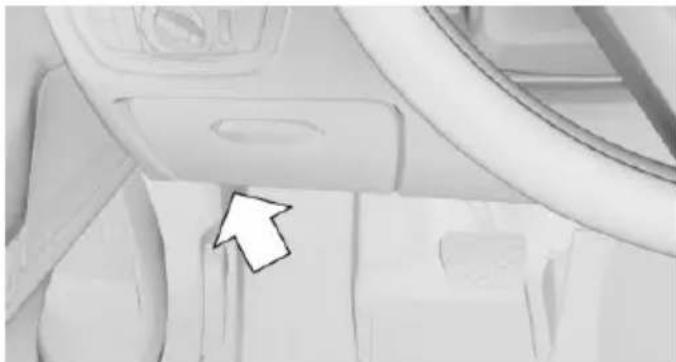
natural_image
Interior view of a vehicle dashboard with no visible text or symbolsThere is an OBD socket on the driver's side for checking the primary components in the vehicle's emissions.
Emissions

The warning lamp lights up:
Emissions are deteriorating. Have the vehicle checked as soon as possible.
The warning lamp flashes under certain circumstances:
This indicates that there is excessive mis-firing in the engine.
Reduce the vehicle speed and have the system checked immediately; otherwise, serious engine misfiring within a brief period can seriously damage emission con-
trol components, in particular the catalytic converter.
Replacing components
Vehicle features and options
This chapter describes all standard, country-specific and optional features offered with the series. It also describes features that are not necessarily available in your car, e.g., due to the selected options or country versions. This also applies to safety-related functions and systems. The respectively applicable country provisions must be observed when using the respective features and systems.
Onboard vehicle tool kit
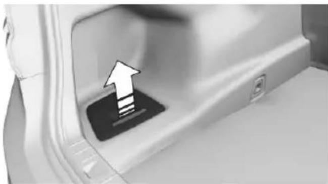
natural_image
Close-up of a car door handle with an arrow pointing upward, indicating a loading or movement (no text or symbols visible)The onboard vehicle tool kit is located in the left storage compartment of the cargo area.
Wiper blade replacement
Information

CAUTION
If the wiper arm falls onto the windshield without the wiper blades installed, the windshield can be damaged. There is risk of property damage. Secure the wiper arm when replacing the wiper blades and do not fold down the wipers without the wiper blades installed.

CAUTION
Folded-away wipers can be jammed when the hood is opened. There is risk of property damage. Make sure that the wipers with the wiper blades mounted are folded down onto the windshield before opening the hood.
Replacing the front wiper blades
- To change the wiper blades, fold up, refer to page 105, the wiper arms.
- Lift the wiper all the way off of the wind-shield.
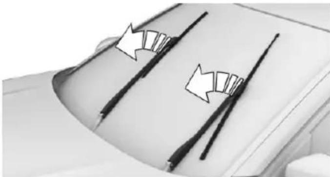
natural_image
Close-up of a car hood with two black metal rods and directional arrows indicating movement or force (no text or symbols)- Press button, arrow 1, and pull out the wiper blade, arrow 2.
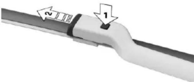
text_image
Diagram of a pipe junction with labeled parts 1 and 2, showing directional arrows indicating flow or movement.- Insert the new wiper blade and press it on until it you hear it snap into the holder.
- Fold down the wipers.
Lights and bulbs
General information
Lights and bulbs make an essential contribution to vehicle safety.
All headlights and lights are made using LED or laser technology.
The vehicle manufacturer recommends that you let a dealer's service center or another qualified service center or repair shop perform the work in case of a malfunction.
Information
Lights and bulbs

DANGER
There can be high voltage in the lighting system. There is danger to life. The manufacturer of your vehicle recommends that the work on the lighting system including bulb replacement be performed by a dealer's service center or another qualified service center or repair shop.
Light-emitting diodes (LEDs)
Some items of equipment use light-emitting diodes installed behind a cover as a light source.
These light-emitting diodes, which are related to conventional lasers, are officially designated as Class 1 light-emitting diodes.

WARNING
Too intensive brightness can irritate or damage the retina of the eye. There is risk of injuries. Do not look directly into the headlights or other light sources for an extended period of time. Do not remove the LED covers.
Headlight glass
Condensation can form on the inside of the external lights in cool or humid weather. When driving with the lights switched on, the con-
densation evaporates after a short time. The headlight glass does not need to be changed.
If despite driving with the lights switched on, increasing humidity forms, e. g. water droplets in the lamp, the manufacturer of your vehicle recommends having it checked by a dealer's service center or another qualified service center or repair shop.
Changing wheels
Information
When using run-flat tires or sealants, a tire does not need to be changed immediately in the event of pressure loss due to a flat tire.
The tools for changing wheels are available as accessories from your dealer's service center or another qualified service center or repair shop.
Jacking points for the vehicle jack
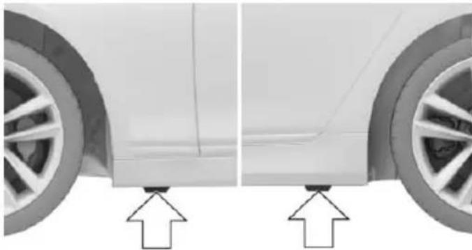
natural_image
Side view of a car showing front and side views with arrows pointing to the lower side (no text or symbols present)The jacking points for the vehicle jack are located at the positions shown.
Emergency wheel
Safety measures
Park the vehicle as far away as possible from passing traffic and on solid ground. Switch on the hazard warning system.
▷ Set the parking brake and engage lever in position P P.
▶ Have all vehicle occupants get out of the vehicle and ensure that they remain outside the immediate area in a safe place, such as behind a guardrail.
▶ If necessary, set up a warning triangle or portable hazard warning lamp at an appropriate distance.
▶ Perform wheel change only on a flat, solid and slip-resistant surface. On soft or slippery ground, e.g., snow, ice, tiles, etc., the vehicle or vehicle jack can slip away to the side.
Do not place wood blocks or similar items under the vehicle jack; otherwise, it cannot reach its carrying capacity because of the restricted height.
▶ If the vehicle is raised, do not lie under the vehicle and do not start the engine; otherwise, a fatal hazard exists.
Information

WARNING
The vehicle jack is optimized for lifting the vehicle and for the jacking points on the vehicle only. There is risk of injuries. Do not lift any other vehicle or cargo using the vehicle jack.
Removing the emergency wheel
The emergency wheel and the tools are located in the trunk under the cargo floor panel.
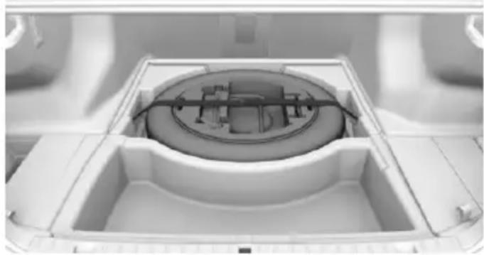
natural_image
Interior view of a white plastic appliance with a circular top and internal compartments (no visible text or symbols)- Remove the cargo floor panel. To do this, pull the floor upward directly behind the rear backrests.
- Loosen the lashing straps.
- Remove tool holder.
- Remove emergency wheel.
Prepare wheel change
- Follow the Safety instructions, refer to page 283.
- With the wheel chock from the onboard vehicle tool kit, also secure the vehicle against rolling away at the front wheel of the opposite side. For this, place the wheel chock behind the front wheel diagonally across.
- Switching off the air suspension, refer to page 200.
- Loosen the wheel lug bolts a half turn.
Jacking up the vehicle
- Place the vehicle jack at the jacking point closest to the wheel such that the vehicle jack foot is vertically beneath the vehicle
jacking point with the entire surface on the ground.
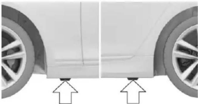
natural_image
Side view of a car showing front wheel and side panel, with two arrows pointing to the lower side (no text or symbols present)- Insert the vehicle jack head in the rectangular recess of the jacking point for cranking it up.
- Crank it up until the wheel in question lifts off of the ground.
Wheel mounting
Mount one emergency wheel only.
- Unscrew the wheel lug bolts and remove the wheel.
- Put the new wheel or emergency wheel on and screw in at least two bolts.
If original BMW light alloy wheels are not mounted, any accompanying lug bolts also have to be used. - Screw in the remaining the lug bolts and tighten all bolts well in a crosswise pattern.
- Lower the vehicle and remove the vehicle jack.
After the wheel change
- Tighten the lug bolts crosswise. The tightening torque is 101 lb ft/140 Nm.
- Stow the nonworking wheel in the trunk. The nonworking wheel cannot be stored under the cargo floor panel because of its size.
- Check tire inflation pressure at the next opportunity and correct as needed.
- Reinitialize the Flat Tire Monitor.
Reset the Tire Pressure Monitor.
- Check to make sure the lug bolts are tight with a calibrated torque wrench.
- Replace the damaged tires as soon as possible.
Driving with emergency wheel

WARNING
The emergency wheel has particular dimensions. When driving with an emergency wheel, changed driving properties may occur at higher speeds, e.g. reduced lane stability when braking, longer braking distance and changed self-steering properties in the limit area. There is risk of an accident. Drive moderately and do not exceed a speed of 50 mph/80 km/h.
Vehicle battery
Maintenance
The battery is maintenance-free.
The added amount of acid is sufficient for the service life of the battery.
More information about the battery can be requested from a dealer's service center or another qualified service center or repair shop.
Battery replacement

CAUTION
Vehicle batteries that are not compatible can damage vehicle systems and impair vehicle functions. There is risk of property damage. Information on the compatible vehicle batteries is available at your dealer's service center.
After a battery replacement, the manufacturer of your vehicle recommends that the vehicle battery be registered on the vehicle by a dealer's service center or another qualified service center or repair shop to ensure that all comfort features are fully available and that any
Check Control messages of these comfort features are no longer displayed.
Charging the battery
General information
Make sure that the battery is always sufficiently charged to guarantee that the battery remains usable for its full service life.
The battery may need to be charged in the following cases:
▶ When making frequent short-distance drives.
▶ If the vehicle is not used for prolonged periods, longer than a month.
Information

CAUTION
Battery chargers for the vehicle battery can work with high voltages and currents, which means that the 12V on-board network can be overloaded or damaged. There is risk of property damage. Only connect battery chargers for the vehicle battery to the starting aid terminals in the engine compartment.
Starting aid terminals
In the vehicle, only charge the battery via the starting aid terminals, refer to page 288, in the engine compartment with the engine off.
Power failure
After a temporary power loss, some equipment needs to be newly initialized or individual settings updated, e. g.:
▶ Seat, mirror, and steering wheel memory: store the positions again.
▶ Time: update.
Date: update.
▷ Glass sunroof: initialize the system, refer to page 75.
Disposing of old batteries

Have old batteries disposed of by a dealer's service center or another qualified service center or repair shop them to a collection point.
Maintain the battery in an upright position for transport and storage. Secure the battery so that it does not tip over during transport.
Fuses
Information

WARNING
Incorrect and repaired fuses can overload electrical lines and components. There is risk of fire. Never attempt to repair a blown fuse and do not replace a nonworking fuse with a substitute of another color or amperage rating.
In the trunk
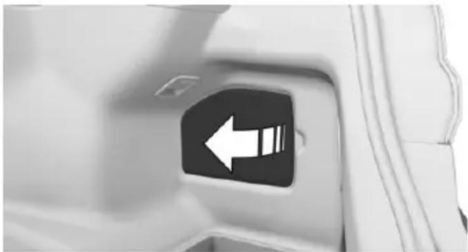
natural_image
Close-up of a car's side panel with a white left-pointing arrow icon (no text or symbols)Remove the cover on the right side trim, arrow.
Information on the fuse types and locations is found on a separate sheet.
Breakdown assistance
Vehicle features and options
This chapter describes all standard, country-specific and optional features offered with the series. It also describes features that are not necessarily available in your car, e.g., due to the selected options or country versions. This also applies to safety-related functions and systems. The respectively applicable country provisions must be observed when using the respective features and systems.
Hazard warning flashers
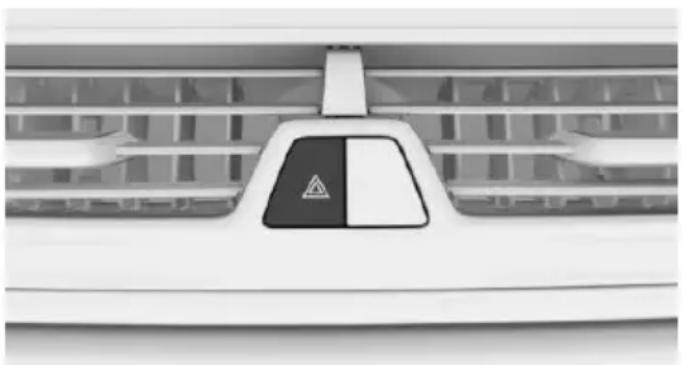
natural_image
Close-up of a white car air conditioner unit with a black warning sign and triangular warning symbol (no text or labels visible)The button is located in the center console.
Intelligent Emergency Request
The concept
In case of an emergency, an Emergency Request can be made through this system.
General information
Only press the SOS button in an emergency.
For technical reasons, the Emergency Request cannot be guaranteed under unfavorable conditions.
Overview
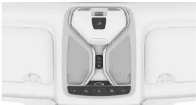
natural_image
Top-down view of a white car interior with a central touchscreen display and two side compartments (no visible text or symbols)SOS button in the roofliner.
Requirements
The SIM card integrated in the vehicle has been activated.
▶ Operating readiness is switched on.
The Assist system is functional.
Initiating an Emergency Request
- Touch the cover.
- Press the SOS button and hold until the LED on the microphone lights up green.
The LED lights up green: an Emergency Request was initiated.
If a cancel prompt appears on the display, the Emergency Request can be aborted.
If the situation allows, wait in your vehicle until the voice connection has been established.
The LED flashes green when a connection to the BMW Response Center has been established.
When the emergency request is received at the BMW Response Center, the BMW
Response Center contacts you and takes further steps to help you.
Even if you are unable to respond, the BMW Response Center can take further steps to help you under certain circumstances.
For this, data are transmitted to the BMW Response Center which serve to determine the necessary rescue measures. E. g. the current position of the vehicle, if it can be established.
If the LED is flashing green, but the BMW Response Center can no longer be heard via the speaker, you can nevertheless still be heard at the BMW Response Center.
Initiating an Emergency Request automatically
Under certain conditions, an Emergency Request is automatically initiated immediately after a severe accident. Automatic Collision Notification is not affected by pressing the SOS button.
Warning triangle
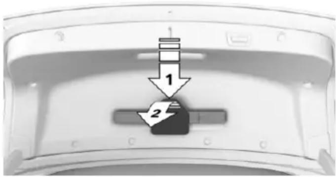
text_image
1 2The warning triangle is located on the inside of the trunk lid.
Press on the release, arrow 1, and swivel the cover down, arrow 2.
First-aid kit
Information
Some of the articles have a limited service life.
Check the expiration dates of the contents regularly and replace any expired items promptly.
Storage
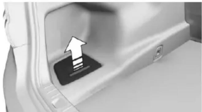
natural_image
Close-up of a car door panel with an upward arrow pointing to the interior (no text or symbols visible)The first-aid kit is located in the left storage compartment of the cargo area.
Jump-starting
General information
If the battery is discharged, the engine can be started using the battery of another vehicle and two jumper cables. Only use jumper cables with fully insulated clamp handles.
Information

DANGER
Contact with live components can lead to an electric shock. There is risk of injuries or danger to life. Do not touch any components that are under voltage.
To prevent personal injury or damage to both vehicles, adhere strictly to the following procedure.
Preparation

CAUTION
In the case of body contact between the two vehicles, a short circuit can occur during jump-starting. There is risk of property damage. Make sure that no body contact occurs.
- Check whether the battery of the other vehicle has a voltage of 12 volts. This information can be found on the battery.
- Switch off the engine of the assisting vehicle.
- Switch off any electronic systems/power consumers in both vehicles.
Starting aid terminals

WARNING
If the jumper cables are connected in the incorrect order, sparks formation can occur. There is risk of injuries. Pay attention to the correct order during connection.
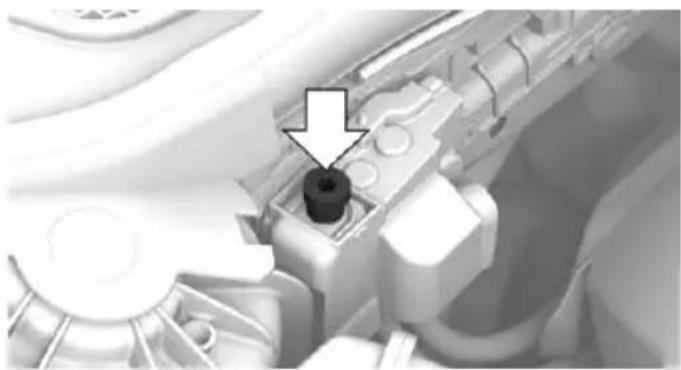
natural_image
Close-up of a mechanical component with a black circular feature and an arrow pointing to it (no visible text or symbols)The so-called starting aid terminal in the engine compartment acts as the battery's positive terminal.
Open the cover of the starting aid terminal.
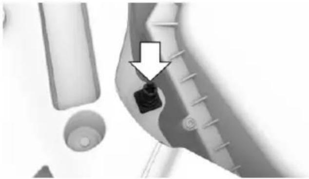
natural_image
Close-up of a mechanical component with a black arrow pointing to a specific part (no visible text or symbols)A special nut serves as the negative terminal of the battery.
Connecting the cables
Before you begin, switch off all unnecessary electronic systems/power consumers, such as the radio, on the assisting and receiving vehicles.
- Open the cover of the starting aid terminal.
- Attach one terminal clamp of the positive jumper cable to the positive terminal of the battery, or to the corresponding starting aid terminal of the vehicle providing assistance.
- Attach the terminal clamp on the other end of the cable to the positive terminal of the battery, or to the corresponding starting aid terminal of the vehicle to be started.
- Attach one terminal clamp of the negative jumper cable to the negative terminal of the battery, or to the corresponding engine or body ground of assisting vehicle.
- Attach the second terminal clamp to the negative terminal of the battery, or to the corresponding engine or body ground of the vehicle to be started.
Starting the engine
Never use spray fluids to start the engine.
- Start the engine of the assisting vehicle and let it run for several minutes at an increased idle speed.
- Start the engine of the vehicle that is to be started in the usual way.
If the first starting attempt is not successful, wait a few minutes before making another attempt in order to allow the discharged battery to recharge.
- Let both engines run for several minutes.
- Disconnect the jumper cables in the reverse order.
Check the battery and recharge if needed.
Tow-starting and towing
Information

WARNING
Due to system limits, individual functions can malfunction during tow-starting/towing with the Intelligent Safety systems activated, e.g. approach control warning with light braking function. There is risk of an accident. Switch all Intelligent Safety systems off prior to tow-starting/towing.
Transporting the vehicle
Information

CAUTION
The vehicle can be damaged when towing the vehicle with a single lifted axle. There is risk of property damage. The vehicle should only be transported on a loading platform.

CAUTION
When lifting the vehicle by the tow fitting or body and chassis parts; damage can occur on vehicle parts. There is risk of property damage. Lift vehicle using suitable means.

CAUTION
With transport on a loading platform, do not fasten vehicle by the chassis.
Tow truck
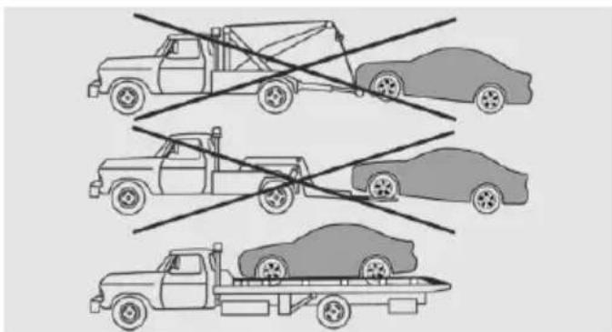
natural_image
Three cartoon-style cars with horizontal lines indicating no movement or collision (no text or symbols)The vehicle should only be transported on a loading platform.
Towing other vehicles
Information

WARNING
If the approved gross vehicle weight of the towing vehicle is lighter than the vehicle to be towed, the tow fitting can tear off or it will not be possible to control the vehicle's response. There is risk of an accident! Make sure that the gross vehicle weight of the towing vehicle is heavier than the vehicle to be towed.

CAUTION
If the tow bar or tow rope is attached incorrectly, damage to other vehicle parts can occur. There is risk of property damage. Correctly attach the tow bar or tow rope to the tow fitting.
▶ Switch on the hazard warning system, depending on local regulations.
If the electrical system has failed, clearly identify the vehicle being towed by placing a sign or a warning triangle in the rear window.
Tow bar
The tow fittings used should be on the same side on both vehicles.
Should it prove impossible to avoid mounting the tow bar at an offset angle, please observe the following:
▶ Maneuvering capability is limited going around corners.
The tow bar will generate lateral forces if it is secured with an offset.
Tow rope
When starting to tow the vehicle, make sure that the tow rope is taut.
To avoid jerking and the associated stresses on the vehicle components when towing, always use nylon ropes or nylon straps.
Tow fitting
General information
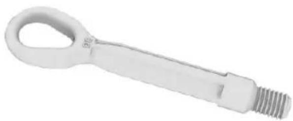
natural_image
White mechanical tool with a loop handle and threaded end (no text or symbols visible)The screw-in tow fitting should always be carried in the vehicle.
The tow fitting can be screwed in at the front or rear of the BMW.
The tow fitting is found in the onboard vehicle tool kit, refer to page 281.
Information

CAUTION
If the tow fitting is not used as intended,
there can be damage to the vehicle or to the tow fitting. There is risk of property damage.
Observe the notes on using the tow fitting.
Use of the tow fitting:
▶ Use only the tow fitting provided with the vehicle and screw it all the way in.
▶ Use the tow fitting for towing on paved roads only.
▶ Use tow fitting located in the front only for positioning the vehicle.
Avoid lateral loading of the tow fitting, e.g., do not lift the vehicle by the tow fitting.
Screw thread for tow fitting
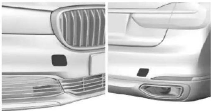
natural_image
Side-by-side comparison of a car's front and rear views, showing grille grilles and dashboard (no text or symbols)Push out the cover by pressing on the top edge.
Tow-starting
Steptronic transmission
Do not tow-start the vehicle.
Tow-starting the engine is not possible due to the transmission.
Have the cause of the starting problems fixed.
Care
Vehicle features and options
This chapter describes all standard, country-specific and optional features offered with the series. It also describes features that are not necessarily available in your car, e.g., due to the selected options or country versions. This also applies to safety-related functions and systems. The respectively applicable country provisions must be observed when using the respective features and systems.
Car washes
General information
Regularly remove foreign objects such as leaves in the area below the windshield when the hood is raised.
Wash your vehicle frequently, particularly in winter. Intense soiling and road salt can damage the vehicle.
Steam blaster and high-pressure washer
Information

CAUTION
When cleaning with high-pressure washers, components can be damaged due to the pressure or temperatures being too high.
There is risk of property damage. Maintain sufficient distance and do not spray too long continuously. Follow the user's manual for the high-pressure washer.
Distances and temperature
▶ Maximum temperature: 140 °F/60 °C.
▶ Minimum distance from sensors, cameras, seals: 12 in/30 cm.
▶ Minimum distance from glass sunroof: 31.5 inches/80 cm.
Automatic car washes
Information
Note the following:
▶ Give preference to cloth car washes or those that use soft brushes in order to avoid paint damage.
▶ Make sure that the wheels and tires are not damaged by the transport mechanisms.
▶ Fold in the exterior mirrors; otherwise, they may be damaged, depending on the width of the vehicle.
▶ Deactivate the rain sensor, refer to page 104, to avoid unintentional wiper activation.
In some cases, an unintentional alarm can be triggered by the interior motion sensor of the alarm system. Follow the instructions on avoiding an unintentional alarm, refer to page 70.

CAUTION
Too high guide rails in car washes can damage body parts. There is risk of property damage. Avoid car washes with guide rails higher than 4 in/10 cm.
Before driving into a car wash
In order to ensure that the vehicle can roll in a car wash, take the following steps:
- Drive into the car wash.
- Engage selector lever position N.
- Deactivating Automatic Hold, refer to page 102.
- Release the parking brake.
- Switch off drive readiness.
In this way, operating readiness remains switched on, and a Check-Control message is displayed.
The vehicle cannot be locked from the outside when in selector lever position N. A signal sounds when an attempt is made to lock the vehicle.
For activation of drive readiness:
- Depress the brake pedal.
- Press the Start/Stop button.
When the Start/Stop button is pressed without stepping on the brake, a Check Control message is displayed.
Selector lever position
Selector lever position P is automatically engaged after approx. 25 minutes.
Headlights
Do not rub dry and do not use abrasive or acidic cleansers.
Soak areas that have been dirtied e. g., from insects, with shampoo and wash off with water.
Thaw ice with de-icing spray; do not use an ice scraper.
After washing the vehicle
After washing the vehicle, apply the brakes briefly to dry them; otherwise, braking action can be reduced and corrosion of the brake discs can occur.
Completely remove all residues on the windows, to minimize loss of visibility due to smearing and to reduce wiper noises and wiper blade wear.
Vehicle care
Car care products
The manufacturer of your vehicle recommends using car care and cleaning products from BMW.

WARNING
Cleansers can contain substances that are dangerous and harmful to your health. There is risk of injuries. When cleaning the interior, open the doors or windows. Only use products intended for cleaning vehicles. Follow the instructions on the container.
Vehicle paint
Regular care contributes to driving safety and value retention. Environmental influences in areas with elevated air pollution or natural contaminants, such as tree resin or pollen can affect the vehicle's paintwork. Tailor the frequency and extent of your car care to these influences.
Aggressive substances such as spilled fuel, oil, grease or bird droppings, must be removed immediately to prevent the finish from being altered or discolored.
Matte finish
Only use cleaning and care products suitable for vehicles with matte finish. These are available from a dealer's service center or another qualified service center or repair shop.
Leather care
Remove dust from the leather often, using a cloth or vacuum cleaner.
Otherwise, particles of dust and road grime chafe in pores and folds, and lead to increased wear and premature degradation of the leather surface.
To guard against discoloration, such as from clothing, provide leather care roughly every two months.
Clean light-colored leather more frequently because soiling on such surfaces is substantially more visible.
Use leather care products; otherwise, dirt and grease will gradually break down the protective layer of the leather surface.
Suitable care products are available from a dealer's service center or another qualified service center or repair shop.
Upholstery material care
Vacuum regularly with a vacuum cleaner.
If upholstery is very dirty, e.g., with beverage stains, use a soft sponge or microfiber cloth with a suitable interior cleaner.
Clean the upholstery down to the seams using large sweeping motions. Avoid rubbing the material vigorously.

CAUTION
Open Velcro® fasteners on articles of clothing can damage the seat covers. There is risk of property damage. Ensure that any Velcro® fasteners are closed.
Caring for special components
Light-alloy wheels
When cleaning the vehicle, use only neutral wheel cleaners having a pH value from 5 to 9. Do not use abrasive cleaning agents or steam jets above 140 °F/60 °C. Follow the manufacturer's instructions.
Aggressive, acidic or alkaline cleaning agents can destroy the protective layer of adjacent components, such as the brake disk.
Chrome surfaces
Carefully clean components such as the radiator grille or door handles with an ample supply of water, possibly with shampoo added, particularly when they have been exposed to road salt.
Rubber components
Environmental influences can cause surface soiling of rubber parts and a loss of gloss. For cleaning, use only water and suitable care products, the manufacturer of your vehicle recommends original BMW care products.
Treat especially worn rubber parts with rubber care agents at regular intervals. When cleaning rubber seals, do not use any silicon-containing car care products in order to avoid damage or noises.
Fine wood parts
Clean fine wood facing and fine wood components only with a moist rag. Then dry with a soft cloth.
Plastic components
These include:
▶ Imitation leather surfaces.
▶ Roofliner.
▷ Lamp lenses.
▶ Instrument cluster cover.
▶ Matt black spray-coated components.
▶ Painted parts in the interior.
Clean with a microfiber cloth.
Dampen cloth lightly with water.
Do not soak the roofliner.

CAUTION
Cleansers that contain alcohol or solvents, such as lacquer thinners, heavy-duty grease removers, fuel, or such, can damage plastic parts. There is risk of property damage. Clean with a microfiber cloth. Dampen cloth lightly with water.
Safety belts
Dirty belt straps impede the reeling action and thus have a negative impact on safety.

WARNING
Chemical cleansers can destroy the safety belt webbing. Missing protective effect of the safety belts. There is risk of injuries or danger to life. Use only a mild soapy solution for cleaning the safety belts.
Use only a mild soapy solution, with the safety belts clipped into their buckles.
Do not allow the switches to retract the safety belts until they are dry.
Carpets and floor mats

WARNING
Objects in the driver's floor area can limit the pedal distance or block a depressed pedal. There is risk of an accident. Stow objects in the vehicle such that they are secured and cannot enter into the driver's floor area. Use floor mats that are suitable for the vehicle and can be safely attached to the floor. Do not use loose floor mats and do not layer several floor mats. Make sure that there is sufficient clearance for the pedals. Ensure that the floor mats are securely fastened again after they were removed, e.g. for cleaning.
Floor mats can be removed from the car's interior for cleaning.
If the floor carpets are very dirty, clean with a microfiber cloth and water or a textile cleaner. To prevent matting of the carpet, rub back and forth in the direction of travel only.
Sensor/camera lenses
To clean sensors and camera lenses, use a cloth moistened with a small amount of glass detergent.
Displays/screens/protective glass of the Head-up Display

CAUTION
Chemical cleansers, moisture or fluids of any kind can damage the surface of displays and screens. There is risk of property damage. Clean with a clean, antistatic microfiber cloth.

CAUTION
The surface of displays can be damaged with improper cleaning. There is risk of property damage. Avoid pressure that is too high and do not use any scratching materials.
Clean with a clean, antistatic microfiber cloth.
Clean the protective glass of the Head-up Display, refer to page 126, using a microfiber cloth and commercially available dish-washing soap.
Long-term
When the vehicle is shut down for longer than three months, special measures must be taken. Further information is available from a dealer's service center or another qualified service center or repair shop.
text_image
TUESDAY PUDAY HEDAY Online Edition for Part no. 0140 2 964 330 - VI/15Reference
This chapter contains the technical data and an index that will quickly take you to the information you need.
Technical data
Vehicle features and options
This chapter describes all standard, country-specific and optional features offered with the series. It also describes features that are not necessarily available in your car, e. g., due to
Information
The technical data and specifications in this Owner's Manual are used as guidance values. The vehicle-specific data can deviate from this, for example, due to the selected special equipment, country version or country-specific measurement method. Detailed values can be
Dimensions
The dimensions can vary depending on the model version, equipment or country-specific measurement method.
The specified heights do not take into account attached parts, for example, a roof antenna,
the selected options or country versions. This also applies to safety-related functions and systems. The respectively applicable country provisions must be observed when using the respective features and systems.
found in the approval documents, on labels on the vehicle or can be obtained from a dealer's service center or another qualified service center or repair shop.
The information in the vehicle documents always has priority.
roof racks or spoiler. The heights can deviate, for example, due to the selected special equipment, tires, load and chassis version.
| BMW 7 Series Sedan | |
| Width with mirrors inches/mm | 85.4/2,169 |
| Width without mirrors inches/mm | 74.9/1,902 |
| Height inches/mm | 57.8/1,467 |
| Height L-models inches/mm | 58.2/1,479 |
| Length inches/mm | 201.2/5,108 |
| Length L-models inches/mm | 206.6/5,248 |
| Wheelbase inches/mm | 120.9/3,070 |
| Wheelbase L-models inches/mm | 126.4/3,210 |
| Smallest turning radius diam. ft/m | 41.1/12.5 |
| Smallest turning radius diam. L-models ft/m | 42-42.4/12.8-12.9 |
Weights
| Canada only: 750i xDrive | |
| Approved gross vehicle weight lbs/kg | 5,705/2,588 |
| Load lbs/kg | 960/435 |
| Approved front axle load lbs/kg | 2,840/1,288 |
| Approved rear axle load lbs/kg | 3,060/1,388 |
| Approved roof load capacity lbs/kg | 220/100 |
| Cargo area capacity cu ft | 18.2 |
| Canada: trunk capacity | 18.2/515cu ft/l |
| 740Li | |
| Approved gross vehicle weight lbs/kg | 5,450/2,472 |
| Load lbs/kg | 960/435 |
| Approved front axle load lbs/kg | 2,585/1,173 |
| Approved rear axle load lbs/kg | 3,030/1,374 |
| Approved roof load capacity lbs/kg | 220/100 |
| Cargo area capacity cu ft | 18.2 |
| Canada: trunk capacity | 18.2/515cu ft/l |
| 750Li xDrive | |
| Approved gross vehicle weight lbs/kg | 5,870/2,663 |
| Load lbs/kg | 960/435 |
| Approved front axle load lbs/kg | 2,900/1,315 |
| Approved rear axle load lbs/kg | 3,140/1,424 |
| Approved roof load capacity lbs/kg | 220/100 |
| Cargo area capacity cu ft | 18.2 |
| Canada: trunk capacity | 18.2/515cu ft/l |
Capacities
| US gal/liters Notes | |
| Fuel tank, approx. Fuel quality, refer to | 20.6/78 page 252 |
Appendix
Any updates to the Owner's Manual of the vehicle are listed here.
Everything from A to Z
Index
A
ABS, Antilock Brake System 163
ACC, Active Cruise Control with Stop & Go 168
Acceleration Assistant, see Launch Control 106
Accessories and parts 7
Accident prevention, see Active Protection 160
Activated-charcoal filter 206
Activating gesture control 30
Active Blind Spot Detection 153
Active comfort chassis 201
Active Cruise Control with Stop & Go, ACC 168
Active damping adjustment 201
Active Protection 160
Active roll stabilization 202
Active seat ventilation 92
Active Steering, integral 166
Adaptive brake assistant 163
Adaptive brake lights, see Brake force display 160
ADAPTIVE drive mode, see Driving Dynamics Control 110
Adaptive Light Control 131
ADAPTIVE, see Driving Dynamics Control 110
Additives, oil 275
Adjustments, seats/head re- straints 76
After washing vehicle 292
Airbags 136
Airbags, indicator/warning light 137
Air circulation, see Recircu- lated-air mode 205
Air, dehumidifying, see Cooling function 204
Air distribution, manual 205
Air flow, automatic climate control 205
Air outlets, see ventilation 206
Air pressure, tires 254
Air suspension 200
Alarm system 69
Alarm, unintentional 70
All around the center console 16
All around the roofliner 18
All around the steering wheel 14
All-season tires, see Winter tires 259
All-wheel-drive, see xDrive 165
Alternating-code hand-held transmitter 216
Alternative oil types 275
Ambient air package 211
Ambient light 133, 134
Animal detection, see Night Vision 147
Antifreeze, washer fluid 106
Antilock Brake System, ABS 163
Anti-slip control, see DSC 163
Approved axle load 299
Arrival time 124
Ashtray 217
Ashtray, front 217
Ashtray, rear 218
Assistance when driving off 163
Attentiveness assistant 161
AUC Automatic Recirculating Air Control 205
Audio 6
AUTO H button 100
AUTO H button, see Automatic Hold 100
AUTO intensity 204
Automatic car wash 291
Automatic climate control 203
Automatic Cruise Control with Stop & Go 168
Automatic Curb Monitor 85
Automatic deactivation, Front-seat passenger airbags 138
Automatic headlight control 130
Automatic Hold 100
Automatic locking 68
Automatic Recirculating Air Control AUC 205
Automatic Soft Closing, doors 63
Automatic transmission, see Steptronic transmis- sion 106
Automatic unlocking 68
AUTO program, automatic climate control 204
AUTO program, intensity 204
Auto Start/Stop function 98
Average fuel consumption 124
Average speed 124
Axle loads, weights 299
B
Backrest curvature, see Lumbar support 77
Backrest, seats 76
Backrest, width 77
Band-aids, see First-aid kit 287
Bar for tow-starting/towing 289
Basic position, rear seats 80
Battery replacement, vehicle battery 284
Battery replacement, vehicle remote control 55
Battery, vehicle 284
Being towed, see tow-starting/towing 289
Belts, safety belts 80
Beverage holder, cu- pholder 228
Blinds, sun protection 72
Bluetooth connection 42
BMW Assist 6
BMW display key 55
BMW Driver's Guide App 6
BMW gesture control 30
BMW Homepage 6
BMW Internet page 6
BMW maintenance sys- tem 279
BMW Touch Command 36
Bottle holder, see Cu- pholder 228
Brake assistant 163
Brake assistant, adaptive 163
Brake discs, break-in 234
Brake force display 160
Brake lights, adaptive 160
Brake lights, brake force display 160
Brake pads, break-in 234
Braking, hints 235
Breakdown assistance 286
Break-in 234
Brightness of Control Display 39
Bulb replacement 282
Bulb replacement, front 282
Bulb replacement, front lamps 282
Bulb replacement, rear 282
Bulb replacement, tail lamps 282
Bulbs and lights 282
Button, Start/Stop 97
Bypassing, see Jump-starting 287
C
California Proposition 65 Warning 8
Calling up mirror adjustment 68
Calling up seat adjustment 68
Calling up steering wheel adjustment 68
Camera-based damping adjustment 201
Camera lenses, care 294
Camera, rearview camera, without Surround View 184
Camera, see Surround View 187
Can holder, see Cu- pholder 228
Captain's chair 89
Car battery 284
Car care products 292
Care, displays 294
Care, vehicle 292
Cargo 237
Cargo area, storage compartments 229
Cargo, securing 238
Cargo straps, securing cargo 238
Car key, see Remote control 54
Carpet, care 294
Cartridge replacement, see Ambient air package 211
Car wash 291
Catalytic converter, see Hot exhaust system 235
CBS Condition Based Service 279
Center armrest 227
Center console 16
Central locking system 63
Central screen, see Control Display 21
Changes, technical, see Own Safety 7
Changing parts 281
Changing wheels 282
Changing wheels/tires 258
Chassis number, see vehicle identification number 10
Check Control 114
Checking the engine oil level electronically 273
Checking the oil level electronically 273
Children, seating position 93
Children, transporting safely 93
Child restraint fixing sys- tem 93
Child restraint fixing system LATCH 95
Child restraint fixing systems, mounting 94
Child safety locks 96
Child seat, mounting 94
Child seats 93
Chrome parts, care 293
Cigarette lighter 218
Cleaning displays 294
Climate control 203
Climate control on roof-liner 209
Clock 118
Closing the trunk lid with no-touch activation 66
Closing via door lock 62
Closing without remote control 62
Clothes hooks 229
Coasting 245
Coasting with engine decoupled, coasting 245
Coasting with idling engine 245
Collision warning with braking function 140
Collision warning with City braking function 140
Combination switch, see Turn signals 103
Combination switch, see Wiper system 103
Comfort Access 65
COMFORT drive mode, see Driving Dynamics Control 110
COMFORT PLUS drive mode, see Driving Dynamics Control 110
COMFORT PLUS, see Driving Dynamics Control 110
COMFORT, see Driving Dynamics Control 110
Communication 6
Compact wheel, see Emergency wheel 282
Compartments in the doors 226
Compatible devices 42
Compatible mobile phones 42
Compressor 260
Computer, see on-board computer 122
Condensation on windows 206
Condensation under the vehicle 236
Condition Based Service CBS 279
Confirmation signal 68
ConnectedDrive 6
ConnectedDrive Services 6
Connecting device 41
Connecting electrical devices 219
Connecting mobile phone 41
Connecting smartphone 41
Connecting telephone 41
Connections 41
Continued driving with a flat tire 267, 270
Control Display 21
Control Display, settings 38
Controller 22
Control systems, driving stability 163
Convenient opening with the remote control 61
Coolant 277
Coolant level 277
Coolant temperature 118
Cooler 223
Cooling function 204
Cooling, maximum 204
Cooling system 277
Corrosion on brake discs 236
Cosmetic mirror 217
Courtesy lamps with the vehicle locked 61
Cross traffic warning 197
Cruise control 175
Cruise control, active with Stop & Go 168
Cruising range 123
Cupholder 228
Current fuel consumption 123
D
Damage, tires 258
Damping control, dynamic 201
Data, technical 298
Daytime running lights 131
Defrosting, see Windows, defrosting 206
Dehumidifying, air 204
Deleting personal data 40
Deletion of personal data 40
Departure time, parked-car heating 211
Departure time, parked-car ventilation 211
Destination distance 124
Device list 41
Digital clock 118
Dimensions 298
Dimmable exterior mirrors 86
Dimmable interior rearview mirror 86
Direction indicator, see Turn signals 103
Display in windshield 126
Display lighting, see Instrument lighting 133
Displays 113
Displays, cleaning 294
Disposal, coolant 278
Disposal, vehicle battery 285
Distance control, see PDC 180
Distance to destination 124
Divided screen view, split screen 27
Door handle lighting, see welcome lights 130
Door lock 62
Door lock, see Remote control 54
Doors, Automatic Soft Closing 63
Downhill control 165
Drive mode 110
Drive-off assistant 163
Drive-off assistant, see DSC 163
Drive readiness, see starting the engine 97
Driving Dynamics Control 110
Driving instructions, break-in 234
Driving notes, general 234
Driving stability control systems 163
Driving style analysis 246
Driving tips 234
DSC Dynamic Stability Control 163
DTC Dynamic Traction Control 164
Dynamic Damping Control 201
Dynamic Stability Control DSC 163
Dynamic Traction Control DTC 164
E
ECO PRO 241
ECO PRO, bonus range 243
ECO PRO display 241
ECO PRO drive mode, see Driving Dynamics Control 110
ECO PRO driving mode 241
ECO PRO driving style analysis 246
ECO PRO INDIVIDUAL drive mode, see Driving Dynamics Control 110
ECO PRO INDIVIDUAL, see Driving Dynamics Control 110
ECO PRO mode 241
ECO PRO, route-ahead assis- tant 244
ECO PRO, see Driving Dynamics Control 110
ECO PRO Tip - driving in- struction 243
Electronic oil measurement 273
Electronic Stability Program ESP, see DSC 163
Emergency detection, remote control 55
Emergency release, fuel filler flap 250
Emergency Request 286
Emergency start function, engine start 55
Emergency unlocking, transmission lock 106
Emergency unlocking, trunk lid 65
Emergency wheel 282
Energy control 123
Energy recovery 123
Engine, automatic Start/Stop function 98
Engine, automatic switch-on/off 98
Engine compartment 271
Engine compartment, working in 272
Engine coolant 277
Engine idling when driving, coasting 245
Engine oil 273
Engine oil, adding 274
Engine oil additives 275
Engine oil change 275
Engine oil filler neck 274
Engine oil temperature 118
Engine oil types, suitable 275
Engine start during malfunction 55
Engine start, jump-starting 287
Engine start, see drive readiness 97
Engine stopping, see drive readiness 97
Engine temperature 118
Entering a car wash 291
Entertainment 6
Equipment, interior 215
Error displays, see Check Control 114
ESP Electronic Stability Program, see DSC 163
Exchanging wheels/tires 258
Executive Drive Pro 201
Exhaustion warner 161
Exhaust system 235
Exterior lighting during un-locking 60
Exterior mirror, automatic dimming feature 86
Exterior mirrors 85
External start 287
External temperature display 118
External temperature warning 118
Eyes for securing cargo 238
F
Failure message, see Check Control 114
False alarm, see Unintentional alarm 70
Fan, see Air flow 205
Filler neck for engine oil 274
Fine wood, care 293
First-aid kit 287
Fitting for towing, see tow-starting/towing 289
Flat tire, changing wheels 282
Flat Tire Monitor FTM 268
Flat tire, repairing 260
Flat tire, Tire Pressure Monitor TPM 264
Flat tire, warning lamp 266, 269
Flooding 235
Floor carpet, care 294
Floor mats, care 294
Folding table in the rear 223
Fold-out position, wiper 105
Foot brake 235
Fragrance cartridge, see Ambient air package 211
Fragrance, see Ambient air package 211
Fragrancing, see Ambient air package 211
Front airbags 136
Front center armrest 227
Front cupholder 228
Front fog lights 132
Front passenger seat, adjusting 78
Front-seat passenger airbags, automatic deactivation 138
Front-seat passenger airbags, indicator lamp 138
Front seats 76
FTM Flat Tire Monitor 268
Fuel 252
Fuel consumption, see Average fuel consumption 124
Fuel filler flap 250
Fuel gauge 118
Fuel lid 250
Fuel quality 252
Fuel recommendation 252
Fuel, tank capacity 300
Fuse 285
G
Garage door opener, see Universal Integrated Remote Control 215
Gasoline 252
Gear change, Steptronic transmission 106
Gear shift indicator 120
General driving notes 234
General settings 38
Gentleman function 78
Gesture 30
Gesture control 30
Gesture operation 30
Glare shield 217
Glass sunroof, powered 73
Glove compartment 225
Gross vehicle weight, approved 299
H
Handbrake, see Parking brake 100
Hand-held transmitter, alternating code 216
Hand movement 30
Hazard warning flashers 286
HDC Hill Descent Control 165
Head airbags 136
Headlight control, automatic 130
Headlight courtesy delay fea- ture 130
Headlight courtesy delay fea- ture via remote control 61
Headlight flasher 103
Headlight glass 282
Headlights, care 292
Head restraint pillows 84
Head restraints 76
Head restraints, front 82
Head restraints, rear 83
Head-up Display 126
Head-up Display, care 294
Heating, see Parked-car heating 209
Heavy cargo, stowing 238
High-beam Assistant 132
High beams 103
High beams/low beams, see High-beam Assistant 132
Hill Descent Control HDC 165
Hills 236
Hill start assistant, see Drive-off assistant 163
Holder for beverages 228
Homepage 6
Hood 272
Horn 14
Hotel function, trunk lid 65
Hot exhaust system 235
HUD Head-up Display 126
Hydroplaning 235
|
iBrake — Post Crash 161
Ice warning, see External temperature warning 118
Icy roads, see External temperature warning 118
Identification marks, tires 256
Identification number, see vehicle identification number 10
Idle state, operating and drive readiness 19
iDrive 21
Ignition key, see Remote control 54
Indication of a flat tire 266, 269
Indicator and alarm lamps, see Check Control 114
Indicator lamp, see Check Control 114
Individual air distribution 205
Individual settings, see profiles 58
Inflation pressure, tires 254
Inflation pressure warning FTM, tires 268
Information 6
Initialize, Tire Pressure Monitor TPM 265
Initializing, Flat Tire Monitor FTM 269
Instrument cluster 113
Instrument lighting 133
Integral Active Steering 166
Integrated key 54
Integrated Owner's Manual in the vehicle 49
Intelligent Emergency Request 286
Intelligent Safety 139
Intensity, AUTO program 204
Interior equipment 215
Interior lights 133
Interior lights during unlocking 60
Interior lights with the vehicle locked 61
Interior motion sensor 70
Interior rearview mirror, automatic dimming feature 86
Internet page 6
Interval display, service requirements 119
Ionization, see Ambient air package 211
J
Jacking points for the vehicle jack 282
Joystick, Steptronic transmission 106
Jump-starting 287
K
Key/remote control 54
Keyless Go, see Comfort Access 65
Kickdown, Steptronic transmission 106
Knee airbag 137
L
Label on recommended tires 259
Lamp in the exterior mirror, see Active Blind Spot Detection 153
Lamp in the exterior mirror, see crossing traffic warning 197
Lamp replacement 282
Lamp replacement, front 282
Lamp replacement, rear 282
Lane departure warning 150
Lane margin, warning 150
Language, on the Control
Display 38
Lashing eyes, securing cargo 238
LATCH child restraint sys-
tem 95
Launch Control 106
Leather, care 292
LEDs, replace light-emitting diodes 282
Light alloy wheels, care 293
Light control 131
Lighting 129
Lights 129
Lights and bulbs 282
Light switch 129
List of all messages 40
Load 238
Loading 237
Lock, door 62
Locking, automatic 68
Locking, settings 67
Locking via door lock 62
Locking with remote control 60
Lock, power window 71
Locks, doors, and windows 96
Low beams 129
Low beams, automatic, see High-beam Assistant 132
Lower back support 77
Luggage rack, see Roof-mounted luggage rack 238
Lumbar support 77
M
Maintenance 279
Maintenance requirements 279
Maintenance, service requirements 119
Maintenance system, BMW 279
Make-up mirror 217
Malfunction displays, see Check Control 114
Manual air distribution 205
Manual air flow 205
Manual brake, see Parking brake 100
Manual mode, Steptronic transmission 106
Manual operation, door lock 62
Manual operation, exterior mirrors 85
Manual operation, fuel filler flap 250
Marking, run-flat tires 260
Massage seat, front 88
Massage seat, rear 88
Master key, see Remote control 54
Maximum cooling 204
Maximum speed, display 120
Maximum speed, winter tires 259
Measurement, units of 39
Medical kit 287
Memory for seat, mirrors, steering wheel 87
Menu in instrument cluster 121
Menus 22
Menus, operating, iDrive 21
Messages 40
Messages, see Check Control 114
Microfilter 206
Minimum tread, tires 258
Mirror 85
Mirror memory 87
Mobile communication devices in the vehicle 235
Mobility System 260
Modifications, technical, see Own Safety 7
Moisture in headlight 282
Monitor, see Control Display 21
Mounting of child restraint systems 94
Moving sun visor 217
Multifunction steering wheel, buttons 14
Multimedia 6
N
Navigation 6
Near-field communication 42
Neck restraints, front, see Head restraints 82
Neck restraints, rear, see Head restraints 83
Neutral cleaner, see wheel cleaner 293
New wheels and tires 258
NFC, see near-field communication 42
Night Vision 147
Night Vision device, see Night Vision 147
Nylon rope for tow-starting/towing 289
0
OBD Onboard Diagnosis 280
OBD, see OBD Onboard Diagnosis 280
Object detection, see Night Vision 147
Octane rating, see Recommended fuel grade 252
Odometer 123
Oil 273
Oil, adding 274
Oil additives 275
Oil change 275
Oil change interval, service requirements 119
Oil filler neck 274
Oil types, alternative 275
Oil types, suitable 275
Old batteries, disposal 285
Onboard computer, Control Display 125
On-board computer, instrument cluster 122
Onboard monitor, see Control Display 21
Onboard vehicle tool kit 281
Opening and closing 54
Opening the trunk lid with no-touch activation 66
Opening via door lock 62
Opening without remote control 62
Opening with remote control, closing with remote control, unlocking with remote control 60
Operating concept, iDrive 21
Operating readiness 19
Operating via iDrive 22
Operating with the controller 22
Operation via touchscreen 25
Optional equipment, standard equipment 7
Outside air, see AUC 205
Overheating of engine, see Coolant temperature 118
Own Safety 7
P
Paint, vehicle 292
Pairing device 41
Pairing mobile phone 41
Pairing smartphone 41
Pairing telephone 41
Panorama View, see Surround View 187
Panoramic glass sunroof 73
Parallel parking assistant 193
Park Distance Control PDC 180
Parked vehicle, condensation 236
Parking aid, see PDC 180
Parking assistant 193
Parking brake 100
Parking lights 129
Parking with Automatic Hold 100
Parts and accessories 7
Passenger side mirror, tilting downward 85
PDC Park Distance Control 180
Pedestrian detection, see Night Vision 147
Pedestrian warning with City braking function 144
Personal profile, see profiles 58
Pillows 84
Pinch protection system, glass sunroof 75
Pinch protection system, windows 71
Plastic, care 293
Post Crash — iBrake 161
Power failure 285
Power sunroof, glass 73
Power windows 70
Prescribed engine oil types 275
Pressure, tire air pressure 254
Pressure warning FTM, tires 268
Profiles 58
Profiles, see profiles 58
Programmable memory buttons, iDrive 28
Protective function, glass sunroof 75
Protective function, windows 71
Push-and-turn switch, see Controller 22
Q
Queuing Assistant, see Steering and lane guidance assistant including Traffic Jam Assist 177
R
Radiator fluid 277
Radio 6
Radio-operated key, see Remote control 54
Rain sensor 104
Rear automatic climate control 207
Rear axle steering 166
Rear center armrest 227
Rear collision prevention 159
Rear collision warning 159
Rear cooler 223
Rear drink holder 228
Rear seats 78
Rear seats, basic position 80
Rear vanity mirror 86
Rearview camera, see Surround View 187
Rearview camera, without Surround View 184
Rearview mirror 85
Rear window defroster 206
Recirculated-air mode 205
Recommended fuel grade 252
Recommended tire brands 259
Refueling 250
Remaining range 123
Remote control/key 54
Remote control, malfunction 62
Remote control, universal 215
Remote control with display 55
Replace front fog lamps 282
Replace front lamps 282
Replace headlamps 282
Replace key lights 282
Replace LED front fog lamps 282
Replace LED headlights 282
Replace light-emitting diodes, LEDs 282
Replacement fuse 285
Replace tail lamps 282
Replacing parts 281
Replacing wheels/tires 258
Reporting safety malfunctions 10
RES CNCL button, see Active Cruise Control, ACC 168
RES CNCL button, see Cruise control 175
Reserve warning, see Range 123
Reset, Tire Pressure Monitor TPM 265
Retaining straps, securing cargo 238
Retreaded tires 259
Roadside parking lights 130
Roller sunblinds 72
RON recommended fuel grade 252
Roofliner 18
Roof load capacity 299
Roof-mounted luggage rack 238
Rope for tow-starting/towing 289
Route-ahead assistant 244
RSC Run Flat System Component, see Run-flat tires 260
Rubber components, care 293
Run-flat tires 260
S
Safe braking 235
Safety belt reminder for driver's seat and front passenger seat 81
Safety belts 80
Safety belts, care 293
Safety package, see Active Protection 160
Safety switch, windows 71
Safety systems, airbags 136
Safety systems, see Intelligent Safety 139
Saving fuel 240
Screen, see Control Display 21
Screwdriver, see Onboard vehicle tool kit 281
Screw thread for tow fitting, see tow-starting/towing, thread for tow fitting, see tow-starting/towing 289
Sealant 260
Seat belts, see Safety belts 80
Seat cushion heating 91
Seat heating 91
Seating position for children 93
Seat, mirror, and steering wheel memory 87
Seats 76
Seats, front 76
Seats, rear 78
Seat ventilation 92
Selection list in instrument cluster 121
Selector lever, Steptronic transmission 106
Self-leveling suspension 200
Sensors, care 294
Service and warranty 8
Service requirements, Condition Based Service CBS 279
Service requirements, display 119
Services, ConnectedDrive 6
SET button, see Active Cruise Control, ACC 168
SET button, see Cruise control 175
Settings, locking/unlocking 67
Settings on the Control Display 38
Settings, storing for seat, mirrors, steering wheel 87
Shift paddles on the steering wheel 106
Shoulder support front 77
Shoulder support rear 79
Side airbag 136
Side collision warning 156
Signaling, horn 14
Signals when unlocking 68
Sitting safely 76
Size 298
Ski and snowboard bag 224
Slide/tilt glass roof 73
Smoker's package 217
Snow chains 264
Socket, OBD Onboard Diagnostics 280
Sockets, see Connecting electrical devices 220
Software update 46
SOS button 286
Spare fuse 285
Spare tire, see Emergency wheel 282
Speed, average 124
Speed limiter, display 120
Speed Limit Information 120
Speed warning 125
Split screen 27
Sport displays, torque display, performance display 125
SPORT drive mode, see Driving Dynamics Control 110
SPORT INDIVIDUAL drive mode, see Driving Dynamics Control 110
SPORT INDIVIDUAL, see Driving Dynamics Control 110
Sport program, Steptronic transmission 106
SPORT, see Driving Dynamics Control 110
Stability control systems 163
Start/stop, automatic function 98
Start/Stop button 97
Start function during malfunction 55
Starting, see drive readiness 97
Starting the engine, see drive readiness 97
Status control display, tires 265
Status information, iDrive 27
Status of Owner's Manual 7
Status, vehicle 126
Steering and lane guidance assistant including Traffic Jam Assist 177
Steering, Integral Active Steering 166
Steering wheel, adjusting 87
Steering wheel heating 87
Steering wheel memory 87
Steptronic Sport transmission, see Steptronic transmission 106
Steptronic transmission 106
Stopping the engine, see drive readiness 97
Storage compartment on the center console 226
Storage compartments 225
Storage compartments, locations 225
Storage, tires 260
Storing the vehicle 294
Suitable engine oil types 275
Summer tires, tread 258
Sun visor 217
Supplementary text mes- sage 117
Surround View 187
Suspension settings 110
Switch for Dynamic Driving Control 110
Switch, see Cockpit 14
Symbols 6
Symbols in the status field 27
SYNC program, automatic climate control 206
T
Table 223
Tablet 36
Tachometer 118
Technical changes, see Own Safety 7
Technical data 298
Telephone 6
Temperature, automatic climate control 204
Temperature display for external temperature 118
Temperature, engine oil 118
Tempomat, see Active Cruise Control 168
Terminal, starting aid 288
Text message, supplementary 117
Theft alarm system, see Alarm system 69
Thermal camera, see Night Vision 147
Through-loading system 222
Tilt alarm sensor 70
Time of arrival 124
Tire damage 258
Tire identification marks 256
Tire inflation pressure 254
Tire inflation pressure monitor, see FTM 268
Tire Pressure Monitor TPM 264
Tires, changing 258
Tire sealant 260
Tires, everything on wheels and tires 254
Tires, run-flat tires 260
Tire tread 258
Tone 6
Tool 281
Top View, see Surround View 187
Total vehicle weight 299
Touchpad 26
Touchscreen 25
Tow fitting see tow-starting/towing 289
Towing 289
Towing, see tow-starting/towing 289
Tow-starting 289
TPM Tire Pressure Monitor 264
Traction control 164
TRACTION, driving dynamics 164
Traffic Jam Assist, see Steering and lane guidance assistant 177
Transmission lock, electronic unlocking 106
Transmission, see Steptronic transmission 106
Transporting children safely 93
Tread, tires 258
Trip computer 125
Trip information, see onboard computer on the Control Display 125
Triple turn signal activation 103
Trip odometer 123
Trip recorder, see Trip odometer 123
Trunk lid, closing with no-touch activation 66
Trunk lid, emergency unlocking 65
Trunk lid, hotel function 65
Trunk lid, opening with no-touch activation 66
Trunk lid via remote control 61
Turn signal, bulb replacement 282
Turn signals, operation 103
U
Unintentional alarm 70
Units of measurement 39
Universal remote control 215
Unlock button, Steptronic transmission 106
Unlocking, automatic 68
Unlocking, settings 67
Unlocking via door lock 62
Updates made after the editorial deadline 7
Updating software 46
Upholstery care 293
USB interface 221
V
Vanity mirror 217
Variable steering, Integral Active Steering 166
Vehicle battery 284
Vehicle battery, replacing 284
Vehicle, break-in 234
Vehicle care 292
Vehicle features and options 7
Vehicle identification number 10
Vehicle jack 282
Vehicle paint 292
Vehicle status 126
Vehicle storage 294
Vehicle wash 291
Ventilation 206
Venting, see ventilation 206
Vent, see ventilation 206
Video 6
VIN, see vehicle identification number 10
Vitality programs 90
Vitalization programs, see Vitality programs 90
Voice activation system 33
W
Warning against cross traffic 197
Warning and indicator lamps, see Check Control 114
Warning displays, see Check Control 114
Warning lamp in the exterior mirror, see Active Blind Spot Detection 153
Warning lamp in the exterior mirror, see crossing traffic warning 197
Warning messages, see Check Control 114
Warning triangle 287
Warranty 7
Washer fluid 106
Washer nozzles, wind-shield 105
Washer system 103
Washing, vehicle 291
Water on roads 235
Weights 299
Welcome lamps during un- locking 60
Welcome Light Carpet, see welcome lights 130
Welcome lights 130
Welcome screen 58
Wheel cleaner 293
Wheels, changing 258
Wheels, everything on wheels and tires 254
Wheels, Flat Tire Monitor FTM 268
Wheels, Tire Pressure Monitor TPM 264
WiFi 45
WiFi connection 45
Window defroster, rear 206
Windows, powered 70
Windshield washer fluid 106
Windshield washer nozzles 105
Windshield washer sys- tem 103
Windshield washer system, see washer/wiper sys-tem 103
Windshield wiper, see wiper system 103
Winter storage, care 294
Winter tires, suitable tires 259
Winter tires, tread 258
Wiper 103
Wiper blades, replacing 281
Wiper fluid 106
Wiper, fold-out position 105
Wiper system 103
WLAN connection 44
Wood, care 293
Word match concept, navigation 24
Wrench, see Onboard vehicle tool kit 281
X
xDrive 165
More about BMW
bmwusa.com

The Ultimate Driving Machine®