
112HGN - Oven Vitrokitchen - Free user manual and instructions
Find the device manual for free 112HGN Vitrokitchen in PDF.


User questions about 112HGN Vitrokitchen
0 question about this device. Answer the ones you know or ask your own.
Ask a new question about this device
Download the instructions for your Oven in PDF format for free! Find your manual 112HGN - Vitrokitchen and take your electronic device back in hand. On this page are published all the documents necessary for the use of your device. 112HGN by Vitrokitchen.
USER MANUAL 112HGN Vitrokitchen
DIMENSIONES EXTERNAS
natural_image
Technical line drawing of a door frame with mounting brackets and directional arrows (no text or symbols)Fig. 02
text_image
morsettieraFig. 03
text_image
bloccacave terraFig. 04
text_image
Technical diagram showing three labeled components (A, B, C) of a mechanical assembly or inspection setup with tool and component details.Fig. 05
Fig. 06
text_image
Diagram showing a device with labeled parts A and M, including a tool inserted into a component.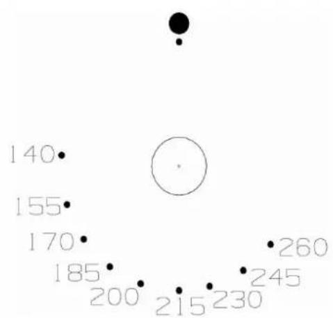
scatter
| X | Y | |---|---| | 140 | | | 155 | | | 170 | | | 185 | | | 200 | | | 215 | | | 230 | | | 245 | | | 260 | |Fig. 07A
scatter
| Point | Value | |---|---| | GRILL | 140 | | | 155 | | | 170 | | | 185 | | | 200 | | | 215 | | | 230 | | | 245 | | | 260 |Fig. 07B

radar
| Point | Value | |---|---| | 1 | 5 | | 2 | 10 | | 3 | 15 | | 4 | 30 | | 5 | 45 | | 6 | 5 | The image displays a single data point (circle) surrounded by eight other discrete points. No axes or legend are present; values are estimated based on the current value ''.Fig. 08
text_image
23:58Fig. 09
text_image
Technical diagram of a door frame with labeled component 'F' and directional arrows indicating rotation or movement.Fig. 10
natural_image
Technical diagram of a mechanical assembly with labeled parts A and B, showing internal components without any text or symbols.Fig. n° 11A
USE AND CARE INSTRUCTIONS
INDEX:
page
IMPORTANT SAFETY INSTRUCTIONS
IMPORTANT POINTS TO FOLLOW 3
3
INSTALLATION INSTRUCTION
BUILT-IN OVEN TO CABINET UNIT 5
CHARACTERISTICS OF CABINET UNIT 5
OVEN ELECTRICAL CONNECTION 6
G A S S U P P L Y
GAS CONVERSION 9
GAS BURNER INJECTOR CONVERSION 9
LOW SETTING VALVE ADJUSTMENT 9
OVEN BURNER TECHNICAL DATA 10
OVEN TECHNICAL DATA 10
INSTRUCTION GUIDE FOR GAS OVEN
IMPORTANT: SAVE THESE INSTRUCTIONS.
IMPORTANT SAFETY INSTRUCTIONS
Read and follow all instructions before using this appliance to prevent the potential risk of fire, electrical shock, personal injury or damage to the appliance as a result of improper usage of the appliance.
WARNING: If the information in this manual is not followed exactly, a fire or explosion may result causing property damage, personal injury or death.
Do not store or use gasoline or other flammable vapours and liquids in the vicinity of this appliance.
WHAT TO DO IF YOU SMELL GAS:
- Do not to light any appliance.
- Do not touch any electrical switch.
- Do not use any phone in your building.
- Immediately call your gas supplier from a neighbour's phone. Follow the gas supplier's instructions.
- If you cannot reach your gas supplier, call the fire department.
Installation and service must be performed by a qualified installer, service agency or the gas supplier.
To ensure proper and safe operation: Appliance must be properly installed and grounded by a qualified installer. Have the installer show you the location of the gas shut off valve and how to shut it off in an emergency.
Always disconnect power to appliance before servicing.
CAUTION: DO NOT LIFT OR MOVE OVEN BY DOOR HANDLES.
IMPORTANT POINTS TO FOLLOW.
Proper installation. Be sure your appliance is properly installed and grounded by a qualified technician.
Never use your appliance for warming or heating the room.
Do Not leave children alone. Children should not be left alone or unattended in area where appliance is in use. They should never be allowed to sit or stand on any part of the appliance.
User servicing. Do not repair or replace any part of the appliance unless specifically recommended in the manual. All other servicing should be referred to a qualified technician.
Storage in appliance. Flammable materials should not be stored in the oven.
Do Not use water on grease fires. Smother fire or flame by using dry chemical or foam-type extinguisher.
Use only dry potholders. Moist or damp potholders on hot surfaces may result in burns from steam. Do not let potholder touch gas burners. Do not use a towel or other bulky cloth.
Glazed cooking utensils. Only certain types of glass, glass/ceramic, ceramic, earthenware, or other glaze utensils are suitable for cooking range use without breaking due to the sudden change in temperature.
Do Not touch oven gas burner or interior oven surface. Surface oven gas burners may be hot even though they have no flame. Areas near surface interior oven surfaces may become hot enough to cause burns. Make sure hot areas have had sufficient time to cool, before touching them.
Use care when opening door. Let hot air or steam escape before removing or replacing food.
Do not heat unopened food containers. Build-up of pressure may cause container to burst and result in injury. Keep oven vent ducts unobstructed.
Placement of oven racks. Always place oven racks in desired location while oven is cool. If rack must be moved while oven is hot, do not let potholder contact hot surfaces in oven.
INSTALLATION INSTRUCTIONS
SPECIAL WARNING:
ONLY QUALIFIED PERSONNEL SHOULD INSTALL OR SERVICE THIS APPLIANCE. READ "SAFETY INSTRUCTIONS" IN THIS BOOK BEFORE USING THIS APPLIANCE. IMPROPER INSTALLATION, ADJUSTMENT, ALTERATION, SERVICE, MAINTENANCE OR USE OF RANGE CAN RESULT IN SERIOUS INJURY OR PROPERTY DAMAGE.
This appliance must be installed in accordance with the manufacturer's installation instructions.
CAUTION: DO NOT LIFT OR MOVE OVEN BY DOOR HANDLES.
BUILT-IN OVEN TO CABINET UNIT:
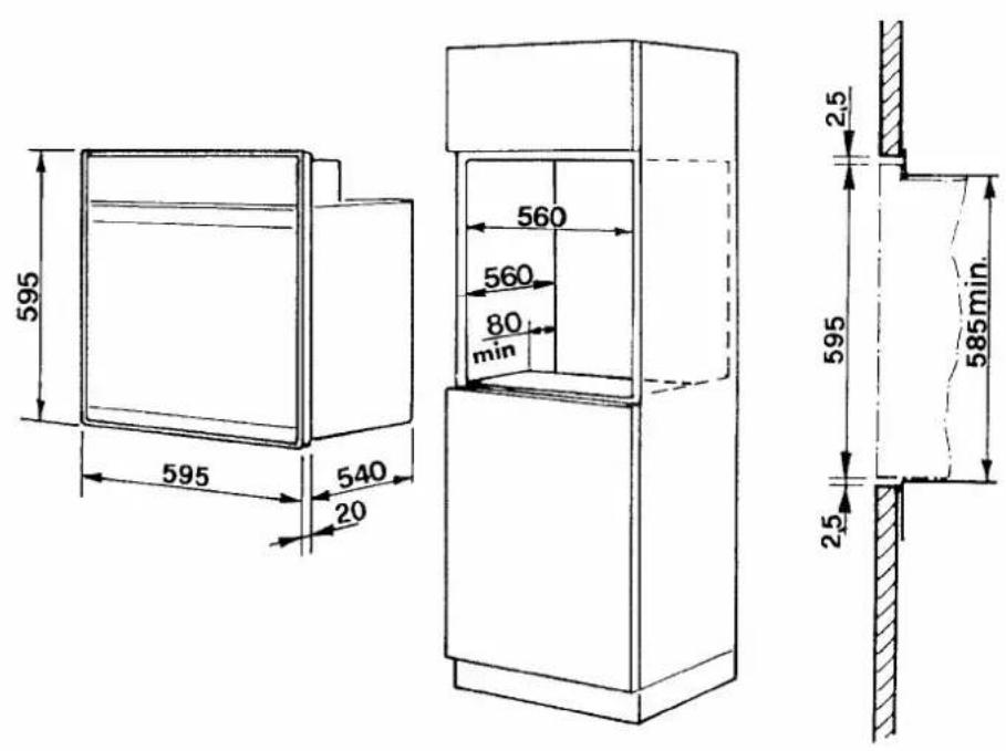
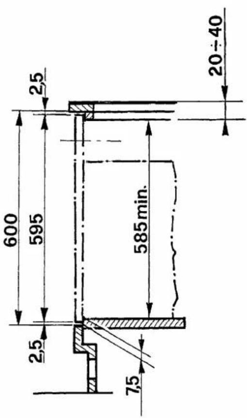
The oven may be built-in either in a column or under countertop of a suitable cabinet unit.
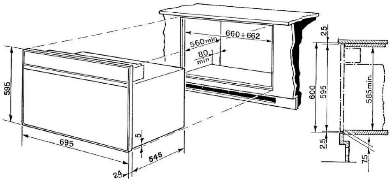
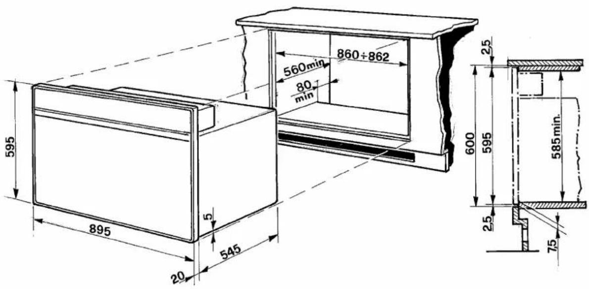
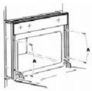
Cut-out opening dimensions to be performed on cabinets are indicated in fig. 1A, 1B and 1C. Make sure cabinet unit in which the oven is to be fitted is sufficiently sturdy to take the weight of the appliance, approx. 35 Kg. for mod. FI 60 and 50 Kg. for mod. FI 70 and FI 90. On the bottom of the unit and/or on the shelf supporting the oven, remember to do the cut-out section at the back, see fig. 1A and 1B, to allow fresh air passage for appliance cooling. Ensure that the oven is firmly fixed on provided cut-out. Use screws “A” fig. 2, to secure oven.
CHARACTERISTICS OF CABINET UNIT: Cabinet Unit technical requirements as follow;
- The unit and its components must be able to resist a temperature of 90^ C without becoming unglued or warped.
- The unit must allow free passage of the electrical connections as well as gas tubing in case is needed.
CAUTION: SOME CABINETS AND BUILDING MATERIALS ARE NOT DESIGNED TO WITHSTAND THE HEAT PRODUCED BY THE NORMAL SAFE OPERATION OF A LISTED APPLIANCE. DISCOLORATION OR DAMAGE, SUCH AS DELAMINATION, MAY OCCUR.
VENTILATION
Ventilation must be in accordance with local installation code. The appliance must be install in a well-ventilated environment to guarantee a correct combustion gases exchange, proper air circulation and working temperature within safety limits.
ATTENTION: In case of appliance failure you must contact the after service authorised person.
MODEL NUMBER PLATE
The Model Number Plate is located on the underneath case. A second Model Number Plate is applied on the front page of the instruction booklet.
- This appliance must be connected to power supply only by a skilled authorised personal.
- Electrical connection must comply with requested local product electrical standard requirements.
- It must be powered by a single-phase 220 – 230 – 240 V \~ 50/60 Hz electrical connection, verify Product Label for correct electrical power voltage and frequency input.
- If electrical wiring is made directly to wall outlet, it is necessary to apply a breaker type of switch suitable to appliance electrical power and standard requirements.
- IN ANY TIME, GROUND WIRING MUST NOT BE INTERRUPTED BY A SWITCH OR SIMILAR COMPONENT.
THE APPLIANCE MUST ALWAYS BE DISCONNECTED FROM POWER SUPPLY BEFORE PERFORMING ANY MAINTENANCE AND SETTINGS.
This appliance is supplied with an electrical flexible cord without plug. In case of plug application, use a suitable plug in accordance to the appliance technical specifications. Remember to properly connect the ground or yellow/green wire to the plug's ground lead In case of flexible cord replacement or application, read following instruction:
- Disconnect electrical power supply.
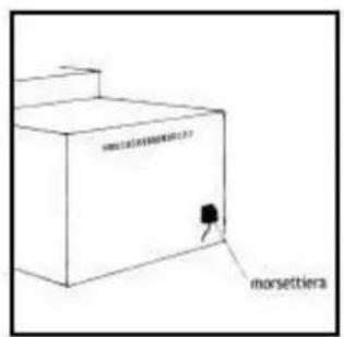
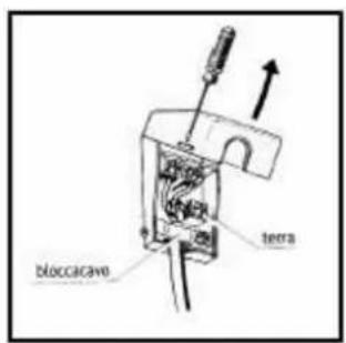
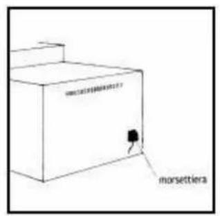
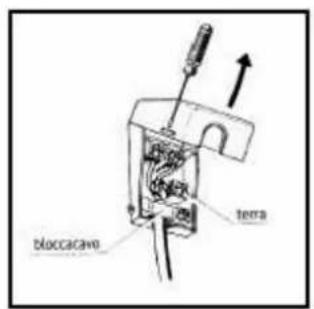
- Open terminal block cover (fig. 3 - 4).
- Fix flexible cord leads properly as indicated in figure 4, Brown Hot (L), Neutral (N) and Ground. Remember the yellow-green lead is ground. If a 13A (BS. 1363) plug is used, fit a 13 amp fuse.
- The flexible cord must always be secured by the cord clamp (fig. 4) on terminal block, so may not become loose by being pulled accidentally. Also, make sure flexible cord does not touch hot point of over 75 °C through out the entire cord length.
- Electrical plug must be suitable to appliance purpose, as mentioned before. Also, position the plug in a location accessible after appliance installation, unless the appliance incorporates or is connected to a switch that ensures all-pole disconnection. This type of switch must have a contact separation in all poles of not less than 3 mm.
ATTENTION: Use only electrical flexible cord with three-prong assembly, for all Single Gas ovens use type H05RR-FH 3 x 0.75 or H05RR-FH 3 x 1.5 for GET and GEVT models.
GAS SUPPLY
GAS SUPPLY CONNECTION:
A TRAINED SERVICEMAN OR GAS APPLIANCE INSTALLER MUST MAKE THE GAS SUPPLY CONNECTION. Leak testing of the appliance shall be conducted by the installer according to the instructions given in section (h).
In case of using Natural gas, supply line must have an inlet pressure of 20 mbar. In case of Liquefied Petroleum L.P. / Propane gas, supply line must have an inlet pressure of 30/37 mbar. Make sure gas pressure does not exceed 50 mbar. otherwise it can damage the appliance gas components and can result in a gas leak.
a) A gas cut-off valve should be put in an accessible location in the supply line ahead of the oven, for turning on and turning off gas supply. If oven is to be connected to house piping with flexible or semi-rigid metal connectors for gas appliances, connector's nuts must not be connected directly to pipe threads. The connectors must be installed with adapters provided with the connector.
b) The house piping and/or oven connector used to connect the oven to the main gas supply must be clean, free of metal shavings rust, dirt and liquids (oil or water). Dirt in the supply lines can work its way into the oven manifold and in turn cause failure of the gas valves or controls and clog burners and/or orifices.
c) Turn off all pilots and main gas valve of other gas appliances.
d) Turn off main gas valve at meter.
e) Before connecting oven apply pipe thread compound approved for LPG to all threads.
f) Connect oven to gas supply using adapters supplied with flexible connector. Rigid pipe may also be used. See rating plate for type of gas to which the oven has been manufactured for.
g) Turn on main gas valve at meter, and relight pilots at other gas appliances.
h) Apply a non-corrosive leak detection fluid to all joints and fittings in the gas connection between the supply line shut-off valve and the range. Include gas fittings and joints in the range if connections were disturbed during installation. Check for leaks!. Bubbles appearing around fittings and connections will indicate a leak. If a leak appears, turn off supply line gas shut-off valve, tighten connections, turn on the supply line gas shut off valve, and retest for leaks.
CAUTION: NEVER CHECK FOR LEAKS WITH A FLAME. WHEN LEAK CHECK IS COMPLETE, WIPE OFF ALL RESIDUE.
i) Remove shipping polystyrene from cooking cavity. This is to hold the racks in place in the cooking cavity for shipping purposes only.
CHECKING PRESSURE OF HOUSE PIPING SYSTEM
1) The appliance and its individual shutoff valve must be disconnected from the gas supply piping system during any pressure testing of that system at test pressure in excess of 35 mbar.
2) The appliance must be isolated from the gas supply piping system by closing its individual manual shutoff valve during any pressure testing of the gas supply piping system at test pressure equal to or less than 35 mbar.
GAS CONVERSION
All gas ovens are equipped with both Natural Gas and LP Gas injectors. The unit model number plate states which gas it was adjusted for at the factory. To convert the unit to either Natural gas or LP gas will require switching burner injectors, burner adjustment for low flame and adjustment of the appliance pressure regulator converter cap.
Inlet pressure to the appliance should be as follows for both operation and checking of appliance pressure regulator setting:
INLET PRESSURE IN mbar.
| PRESSURE | ||
| Minimum | Maximum | |
| Natural gas | 18 | 20 |
| LP gas | 28/35 | 30/37 |
GAS BURNER INJECTOR CONVERSION
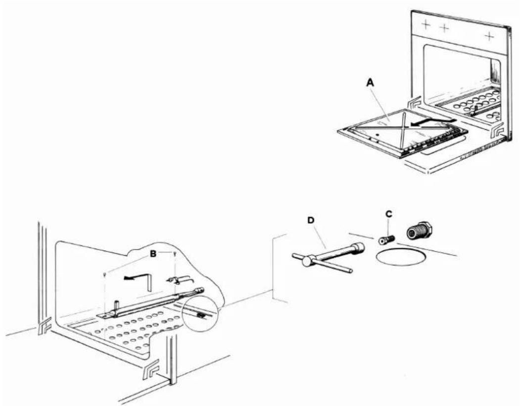
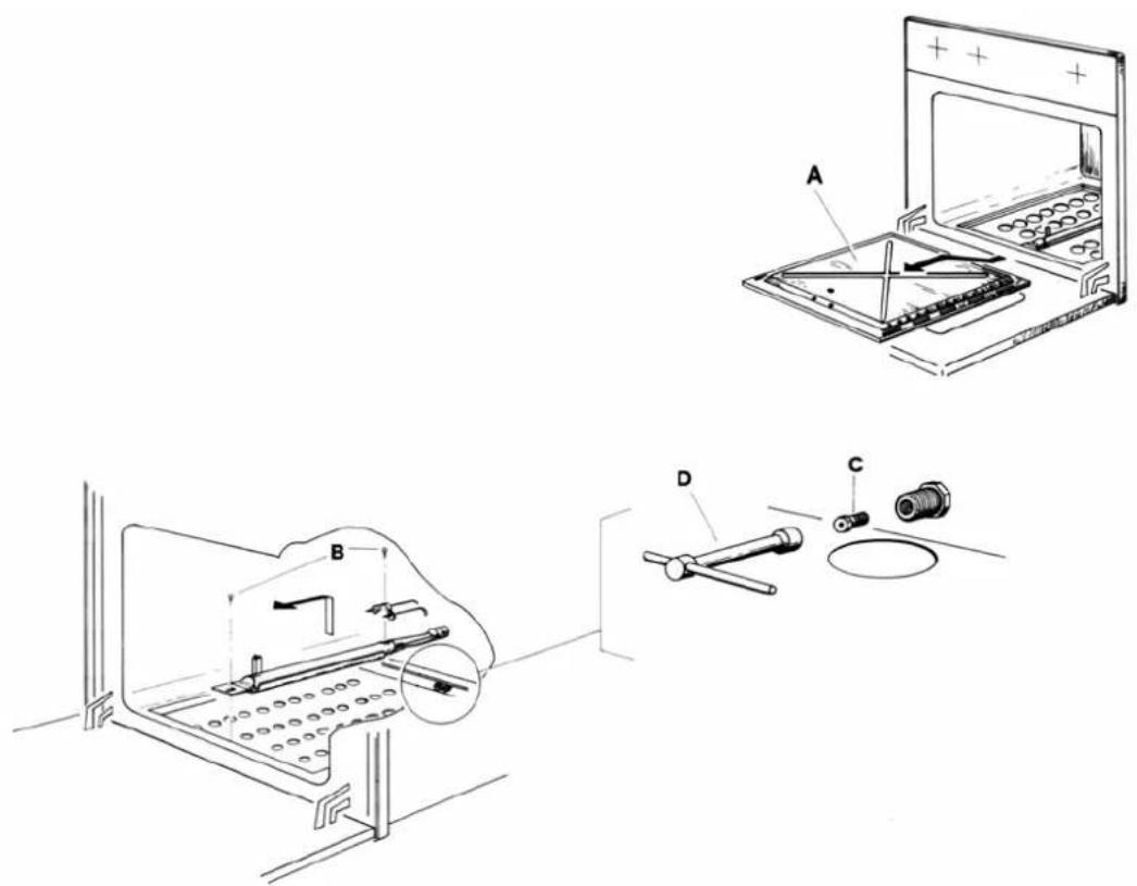
To switch injectors, it is enough to unscrew fixed injector using a proper 7 Hex. key tool and replace it with new injector for new gas setting. For proper injector size, follow Oven Technical Data chart. On Gas Oven Burners, it is not necessary to adjust burner air shutter. Make sure the flame does not lift or blow off the burner when cold. Also in case of excessive yellow flame on burner, call technical assistance to control the appliance. Please see figure 5.
LOW SETTING VALVE ADJUSTMENT
The LOW setting should produce a stable flame when turning the knob from HIGH to LOW. The flame should be stable on all ports on LOW setting.
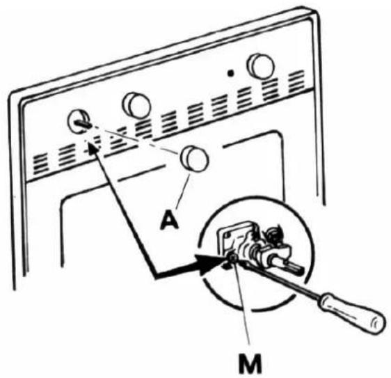
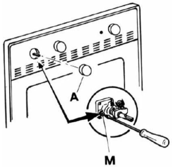
To adjust: Operate burner on HIGH (290 °C) for about five minutes to preheat burner itself. Turn knob back to LOW (150 °C); remove knob, and insert a small flat tip screwdriver into the slotted area on the left centre of the valve stem. Adjust the flame size by turning adjustment screw in either direction, while holding the stem (figure 6).
NOTE: All gas adjustment should be done by a qualified service personnel only.
OVEN BURNER TECHNICAL DATA
| Burner | kW | Gas Press. | Gas Orifice (mm) | |||||
| Nat. / But. / Prop. | Nat. / But. / Prop. | by-pass (mm) | ||||||
| G20 | G30/G31 | G20 | G30/G31 | G20 | G30/G31 | |||
| Oven | 60 | 2.20 | 20 | 30/37 | 110 | 70 | reg. | 0.40 |
| Grill | 60 | 2.10 | 20 | 30/37 | 110 | 72 | - | - |
| Oven | 70 | 2.20 | 20 | 30/37 | 110 | 70 | reg. | 0.40 |
| Oven | 90 | 3.30 | 20 | 30/37 | 130 | 85 | reg. | 0.52 |
| Grill | 90 | 3.30 | 20 | 30/37 | 130 | 85 | - | - |
OVEN TECHNICAL DATA
| ELECTRICAL DATA | FI S(X)60 GET / GEVT / GGVT GAS OVEN | FI S(X)70 GEVT GAS OVEN | FI S(X)90 GEVT GAS OVEN | FI S(X)90 GGVT GAS OVEN |
| VOLTAGE | 220 – 230 – 240 V ~ 50/60 Hz | |||
| TOTAL POWER | 2.2 kW | 2.2 kW | 2.6 kW | 110 W |
| GRILLING GAS BURNER | 2.1 kW | / | 3.2 kW | |
| BOTTOM GAS BURNER | 2.2 kW | 2.2 kW | 3.3 kW | 3.3 kW |
| ELECTRIC GRILL | 1.8 kW | 1.8 kW | 2.5 kW | / |
| OVEN LIGHT | 25 W | 25 W | 25 W | 25 W |
| CONVECTION FAN | 25 W | 25 W | 25 W | 25 W |
| COOLING FAN (IF INSTALLED) | 25 W | 25 W | 25 W | 25 W |
| ROTISSERIE MOTOR | 5 W | 5 W | 1 – 5 W | 1 – 5 W |
USEFUL OVEN INTERIOR DIMENSIONS
| HEIGHT | 30 cm | 31.5 cm | 310 mm | 300 mm |
| WIDTH | 42 cm | 54.5 cm | 710 mm | 710 mm |
| DEPTH | 42 cm | 41.5 cm | 410 mm | 410 mm |
| OVERALL SIZE | 54 lt. | 71 lt. | 90 dm ^3 | 88 dm ^3 |
ENERGY POWER PERFORMANCE
| Consumption with Natural Gas G20 | 210 l/h | 210 l/h | 315 l/h | 315 l/h |
| Consumption with LPG G30 | 160 g/h | 160 g/h | 240 g/h | 240 g/h |
| Total consumption | 2.2 kW/h | 2.2 kW/h | 3.3 kW/h | 3.3 kW/h |
| BROILING AREA | 726 cm ^2 | 726 cm ^2 | 1100 cm ^2 | 1100 cm ^2 |
OVEN ACCESSORIES
| One Dripping Tray | Yes | Yes | Yes | Yes |
| One Cooking Rack, four rack positions | Yes | Yes | Yes | Yes |
DIMENSIONS OF THE APPLIANCES
| Series | Width (cm) | Height (cm) | Depth (cm) |
| FI S(X)60 | 60 | 60 | 55 |
| FI S(X)70 | 70 | 60 | 55 |
| FI S(X)90 | 89 | 60 | 55 |
INSTRUCTION GUIDE FOR GAS OVEN
BAKE GAS BURNER USE
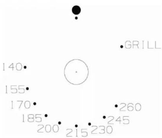
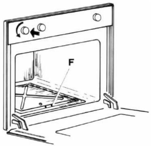
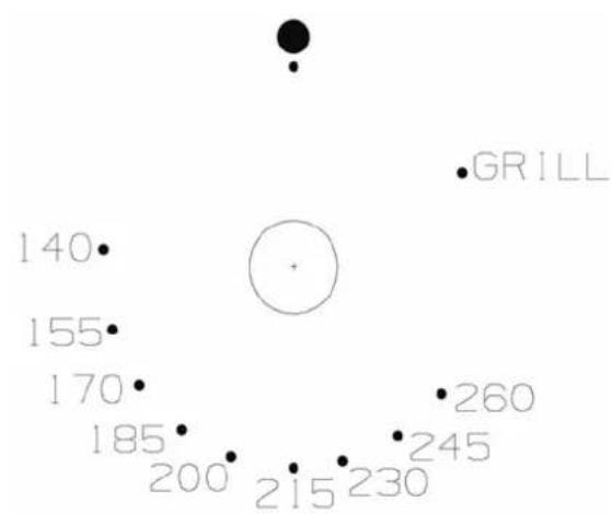
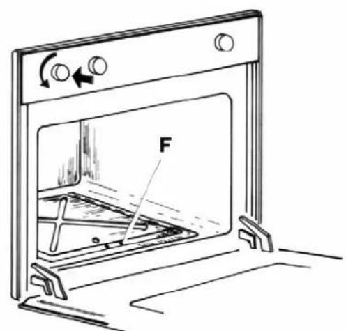
Open the oven door completely, and them push in and turn the thermostat knob anticlockwise to 260 °C setting. See fig. 07A, 07B and 08. A clicking sound will be heard and the burner will light. Look through orifice “F” for burner ignition. Keep pushing knob to allow thermocouple of safety device to warm up enough, for about a period of 10 seconds. Then release the knob and turn it to desired temperature setting.
Attention: During ignition of a newly installed oven and after a long period of inactivity, the gas burner may not ignite at once, so try again till gas comes out to allow ignition, wait a few seconds before trying again to allow excess of gas to dissipate. If problem persist, call an authorised technician for assistance.
Set thermostat to Grill mode by turning knob clockwise. See fig. 07B.
Follow bake gas burner ignition procedure paragraph. Once grill burner is on, allow a period of time for preheating the oven cavity before grilling food.
IMPORTANT: LEAVE OVEN DOOR OPEN WHILE GRILLING. MAXIMUM GRILLING TIME IS 15 MINUTES
SELECTOR SWITCH
This control allows you to turn on the Oven Internal Light or Rotisserie. See fig. 9.

OVEN LIGHT ; (all models)
- Use this setting to turn on Oven light, light also remains on in all other modes.
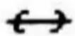
ROTISSERIE ; (all models)
Use this function to broil or roast food using the rotisserie. To use the rotisserie you must preheat the oven using the Grill gas burner. Insert spit with food in the slotted shaft on the back oven wall, then use front support to keep in place the rotisserie spit and apply cooking tray below the rotisserie spit as a grease retainer. Remember to take off the rotisserie handle before closing oven door. For Grilling procedure follow Grill Use chapter.

CONVECTION FAN OR DEFROST ; (GGVT; GEVT only)
Use this setting when Convection is necessary for a more even cooking finish. Also, use this setting to defrost frozen food by speeding up air circulation. This function can not be used while using the grill gas burner.

ELECTRIC GRILL; (all models)
This function operates the full top heating element. This element is used for browning the food and can also be used at the end of a normal cooking period to give extra browning to dishes or give a crisper finish to meat. Pre-heat this function before cooking. Grill for a maximum period of 15 minutes and keeping oven door open.
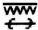
ELECTRIC GRILL WITH ROTISSERIE; (all models)
Grill for a maximum period of 15 minutes and keeping oven door open.
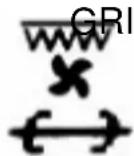
GRILL with CONVECTION FAN and ROTISSERIE (GEVT only)
select this setting to combine the intense heat from the inner top element with the convection fan. This air circulation crisps the exterior surface and retains inner moisture in thick cuts of meat. Also with function allows you to use the Rotisserie spit. Grill for a maximum period of 15 minutes and keeping oven door open.
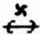
CONVECTION FAN (DEFROST) AND ROTISSERIE.
(GGVT; GEVT only).
This function allows you to defrost food using the rotisserie.
ON AND OFF PILOT LIGHT
Whenever Rotisserie function is selected, the red light goes on.
MINUTE MINDER
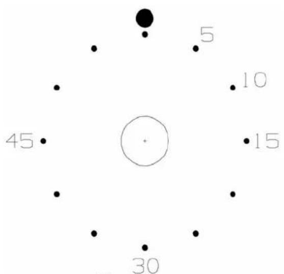
Set required time by turning knob clockwise. As the time set elapses, a bell signal will sound for a few seconds. This timer has only the function of time reminder. It does not stop the oven functions. See fig. 10.
ELECTRONIC TIMER
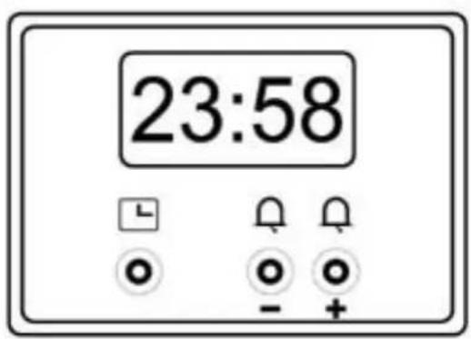
After first electrical power on and in case of any electrical power failure and power has been restored, the electronic timer will start flashing. Fig. 03.
TO SET TIME OF DAY
Press button. Set time of day with "+" and "-" buttons.
This function remains activated 7 seconds after the last “+” / “-” operation.
TO CHANGE TIME OF DAY
Press the button for 4 seconds until the hours display will flash. Change the hours only by using the “+” or “-” button. The minutes and hidden seconds will not be affected.
TO SET TIMER FUNCTION
This function will be activated with “+” button. Press “+” button again to increase duration time.
During setting the count units are in 10 seconds steps or minutes.
During count down the timer has priority on the display. The bell-symbol illuminated. The units are in seconds or minutes in the long time section.
The maximum time is 10h. The format change will happen after 99 minutes and 50 seconds to 1 hour and 40 minutes.
To show time of day press 📁 button, after 6 seconds, the count down comes back on.
TO RESET TIMER
Count down to zero with permanent pressing “-” button (automatic stop at zero).
SIGNAL
The signal after “time out” will stay 7 minutes if it has not been reset with button. The following signal will be skipped if time of day is pressed during the last 15 seconds of the timer.
SIGNAL FREQUENCY
If no function is activated, the signal frequency can be selected by pressing the “-” button. Three different frequencies are selectable.
CAUTION:
1) Do not obstruct the flow of combustion and ventilation air by blocking the room vents or air intakes. Restriction of air flow to the gas appliance prevents proper performance and increases carbon monoxide emission to unsafe levels.
2) If flame should go out during operation, turn the burner off. If a strong gas order is detected, open a window and wait five minutes before relighting the burner.
6) Be sure all control knobs are set in the OFF position prior to supplying gas to the oven.
OVEN RACK PLACEMENT FOR SPECIFIC FOODS:
1) Frozen pies, large roast, turkey, angel food cakes, thick well-done meat cuts; rack position is 1^st or 2^nd rack guide from the bottom.
2) Bundt cake, most quick breads, yeast breads, casseroles, meats, thick meat cuts; rack position is 2^nd rack guide from bottom.
3) Cookies, biscuits, muffins, cakes, non frozen pies, thin meat cuts; rack position is 2^nd and 3^rd rack guide from bottom.
4) For Grilling food; rack position is 4^th rack guide from bottom.
5) For Grilling toast bread; rack position is 5^th rack guide from bottom.
MAINTENANCE
CLEANING SAFETY
Turn off all controls and wait for appliance parts to cool before touching or cleaning them. Do not touch oven inner surface or surrounding areas until they have had sufficient time to cool.
Clean appliance with caution. Use care to avoid steam burns if a wet sponge or cloth is used to wipe spills on a hot surface. Some cleaners can produce noxious fumes if applied to a hot surface.
SURFACE AND OVEN COOKING CAVITY CLEANING
This is easily done using a damp cloth and a non-abrasive detergent, wipe using a soft dry cloth. For stainless steel parts with stubborn soils. Use only plastic scrubbing pad or a sponge with vinegar and warm water.
Because of many new cleaning products introduced in the marketplace each year, it is not possible to list all products that can be safely be used to clean this appliance. Read carefully the cleaner manufacture's instructions to be sure the cleaner can be safely used on this appliance. Although, to determine if a cleaning product is safe, test a small inconspicuous area using a very light pressure to see if the surface may scratch or discolour. This particular important for porcelain enamel, highly polished, shiny, painted or plastic surfaces.
OVEN DOOR
TO REMOVE OVEN DOOR
1) Fully open the oven door.
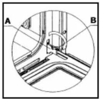
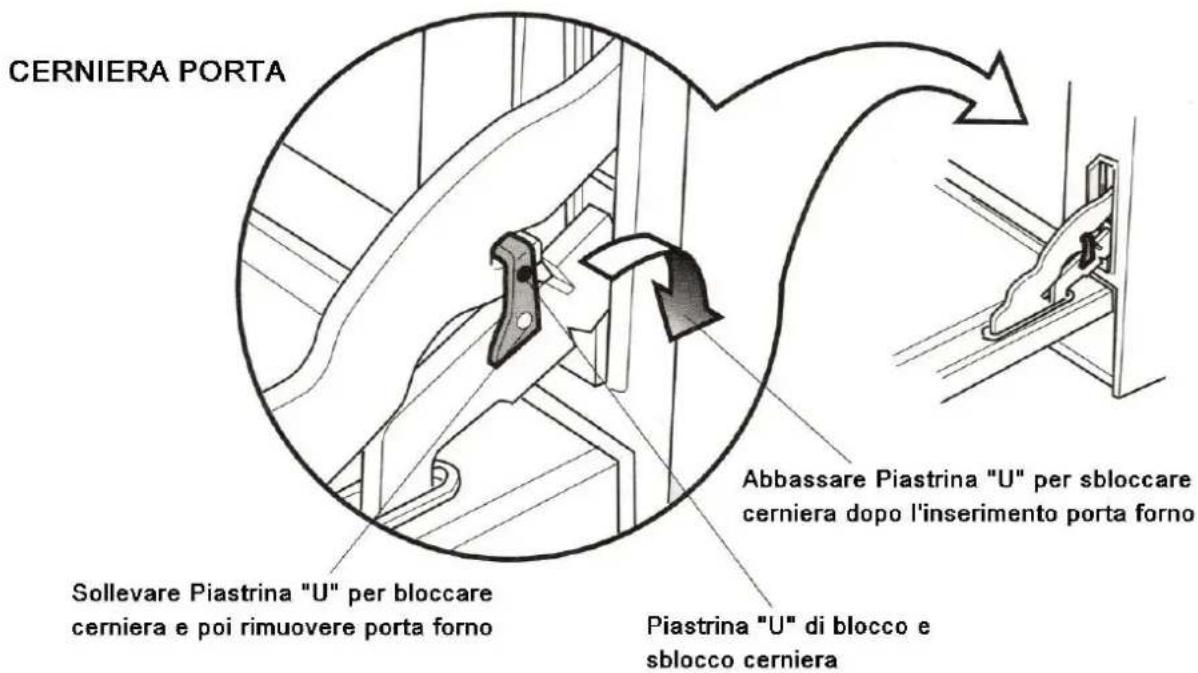
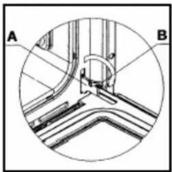
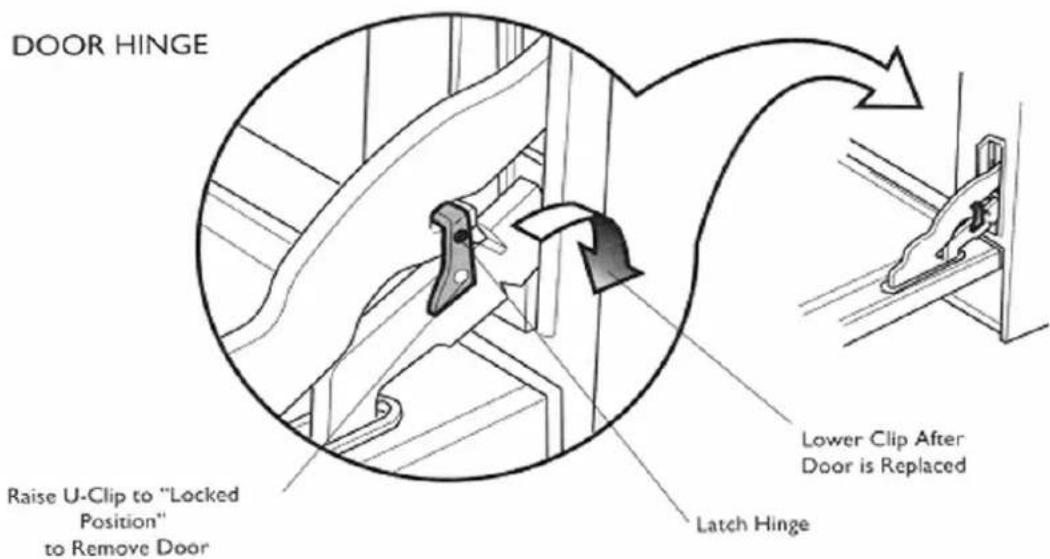
2) Raise and open the U-clip (B) over the hook on each of the hinges (A) all the way to the front, see figure 11A and 11B.
3) Grasp the door by the sides toward the back. Raise the front of the door a few inches and make sure the U-clip (B) is locked by the door frame. This will prevent the hinge from snapping closed when the door is removed. (there will be some spring resistance to overcome because of the hinge being locked). When the front of the door is high enough and hinges are locked, you will be able to lift the hinges to clear the slots
4) Pull the hinges out of the slots in the oven front frame.
TO REPLACE THE OVEN DOOR
1) Grasp the sides of the door at the centre and insert the ends of the hinges (A) and fix the slots in the oven front frame.
2) With the door open all the way, push-back the two U-clips (B) into the hinge (A).
3) Raise the oven door and make sure that it fits evenly with the front sides.
WARNING: Never release the U-clip levers when the door is off. Do not close the hinges without the weight of the door, the powerful springs will snap the hinges closed with great force.
CAUTION: Do not place excessive weight on or stand on an open oven door.
This could cause the range to tip over, break the door, or injure the user.
Also, do not attempt to open or close door or operate oven until door is properly replaced.
REPLACING THE OVEN LIGHT
WARNING; To prevent electrical shock and or personal injury:
1) Before replacing the light bulb, be sure the electric power is turned off at the circuit breaker.
2) Do not operate the oven unless the light cover is securely in position.
3) Be sure the oven and light bulb are cool.
4) Do not touch hot bulb with a damp cloth as this may cause the bulb to break.
5) If the light cover is damaged or broken, do not use the oven until a new cover is in place.
To replace oven light bulb:
1) Before replacing light bulb, disconnect oven electric circuit.
2) Remove oven racks.
3) Remove, unscrewing, lens bulb cover and light bulb.
4) Replace bulb with a 25 W – 230 Vac appliance bulb only.
5) Replace lens bulb cover.
6) Reconnect power to range. Reset electronic clock.
SERVICE – PARTS INFORMATION
When your appliance requires service or replacement parts, contact your dealer or authorised service agency. Please give the complete model and serial number of the appliance, which is located on the oven model number plate
In our continuing effort to improve the quality and performance of our cooking products, it may be necessary to make changes to the appliance without revising this guide. The manufacturer does not take any responsibility on booklet printing mistakes.
THE MANUFACTURER DECLINES ANY LEGAL AND WARRANTY RESPONSIBILITY FOR NOT FOLLOWING INSTALLATION AND WIRING INSTRUCTION IN ACCORDANCE WITH ELECTRICAL EUROPEAN STANDARDS AS WELL AS APPLIANCE USER MISUSE.
FIGURES
text_image
25 600 595 25 7.5 585 min. 20÷40Fig. 1A
text_image
595 695 5 545 2A 80 min 560 min 660 + 662 2.5 600 595 585 min. 2.5 7.5Fig. 1B for FIS(X)70 BUILT-IN OVEN
text_image
595 895 20 5 545 560min 80 min 860÷862 25 600 595 25 585min. 75Fig. 1C for FIS(X)90 BUILT-IN OVEN
natural_image
Technical line drawing of a door frame structure with mounting feet and dimension lines (no text or symbols)Fig. 2
text_image
morsettieraFig. 3
text_image
bloccacavo terraFig. 4
text_image
Technical diagram showing a kitchen appliance with labeled parts A, B, C, D and internal components like a stove or tool.Fig. 5
Fig. 6
text_image
Diagram showing a device with labeled parts A and M, including a tool inserted into a component.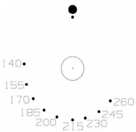
scatter
| X | Y | |---|---| | 140 | | | 155 | | | 170 | | | 185 | | | 200 | | | 215 | | | 230 | | | 245 | | | 260 | |Fig. 7A
scatter
| Point | Value | |---|---| | GRILL | 140 | | | | | | 155 | | | 170 | | | 185 | | | 200 | | | 215 | | | 230 | | | 245 | | | 260 |Fig. 7B
text_image
Diagram of a kitchen oven with labeled component 'F' and directional arrows indicating rotation or movementFig. 8
radar
| Point | Value | |---|---| | 1 | 5 | | 2 | 10 | | 3 | 15 | | 4 | 30 | | 5 | 45 | The chart displays a single data point at the center (circle), which is positioned at the origin of the circle. The other seven points are represented as dots arranged radially around the circle.Fig. 10
natural_image
Technical diagram of a mechanical assembly with labeled parts A and B, showing internal components without any text or symbols.Fig. n° 11A
text_image
DOOR HINGE Raise U-Clip to "Locked Position" to Remove Door Lower Clip After Door is Replaced Latch HingeFig. n° 11B