
MSZ-WG25VA-H1 - Air-conditioner MITSUBISHI - Free user manual and instructions
Find the device manual for free MSZ-WG25VA-H1 MITSUBISHI in PDF.


| Product Type | Split-type air conditioner (indoor unit) |
| Model | MSZ-WG25VA-H1 |
| Brand | Mitsubishi Electric |
| Cooling Capacity | 2.5 kW (approx. 9,000 BTU/h) |
| Heating Capacity | 3.2 kW (approx. 11,000 BTU/h) |
| Power Source | 230 V, 50 Hz, single phase |
| Dimensions (H x W x D) | 307 x 798 x 238 mm |
| Weight (indoor unit) | 11.5 kg |
| Refrigerant | R32 |
| Compressor Type | Inverter (variable speed) |
| Airflow Rate (cooling) | Up to 600 m³/h |
| Noise Level (indoor) | 20 - 45 dB(A) |
| Energy Efficiency Class | A++ |
| Functions | Cooling, Heating, Dehumidification, Fan only, Auto mode |
| Air Filter Type | Washable pre-filter, optional anti-allergy filter |
| Sleep Mode | Yes |
| Timer | 24-hour programmable timer |
| Remote Control | Infrared, with LCD display |
| Self-Cleaning Function | Yes |
| Maintenance | Clean filter every 2 weeks; professional service annually |
| Safety Features | Auto restart, overheat protection, anti-freeze |
| Spare Parts Available | Remote control, filters, fan motor, main PCB (contact service) |
| Repairability Index | 8.4 / 10 (typical for Mitsubishi) |
| General Information | Designed for residential use; outdoor unit sold separately |
Frequently Asked Questions - MSZ-WG25VA-H1 MITSUBISHI
User questions about MSZ-WG25VA-H1 MITSUBISHI
0 question about this device. Answer the ones you know or ask your own.
Ask a new question about this device
Download the instructions for your Air-conditioner in PDF format for free! Find your manual MSZ-WG25VA-H1 - MITSUBISHI and take your electronic device back in hand. On this page are published all the documents necessary for the use of your device. MSZ-WG25VA-H1 by MITSUBISHI.
USER MANUAL MSZ-WG25VA-H1 MITSUBISHI
OPERATING AND INSTALLING INSTRUCTIONS
R410A
制品名
MSZ-WG20VA-H1
MSZ-WG25VA-H1
目 錄
使用安全事項 1
各部件名稱 3
操作前的準備工作 4
natural_image
Simple line drawing of a window with curtains and a patterned rug on a table (no text or symbols)注意
natural_image
Technical line drawing of a mechanical component with a coiled spring or pipe (no text or symbols)| Model | MSZ-WG20VA-H1 | MSZ-WG25VA-H1 |
| Protection class | I Type | |
| Power supply | 220V~50Hz | |
| Cooling capacity (W) | 6000(1840~6700) | 7200(2850~8000) |
| Heating capacity (W) | 7000(1500~8700) | 9000(2420~10300) |
| Power input of cooling (W) | 1700(315~2260) | 2340(570~3300) |
| Power input of Heating (W) | 1950(280~2610) | 3300(550~3660) |
| Cooling rated current (A) | 8.0 | 10.9 |
| Heating rated current (A) | 9.1 | 15.3 |
| Medium cooling capacity (W) | 3000 | 3600 |
| Medium heating capacity (W) | 3500 | 4500 |
| Power input of medium cooling (W) | 560 | 740 |
| Power input of medium heating (W) | 730 | 1000 |
| Heating capacity in low temperature (W) | 6300 | 7450 |
| Power input of heating in low temperature (W) | 2220 | 3100 |
| Air flow volume (cooling/heating) (m3/h) | 900/960 | 900/960 |
| Refrigerant charging (g) | 2050 | 2200 |
| Indoor noise cooling (dB(A)) (SHi/Lo) | 46/36 | 46/36 |
| Indoor noise heating (dB(A)) (SHi/Lo) | 44/30 | 44/30 |
| Outdoor noise (cooling/heating) (dB(A)) | 53/55 | 53/55 |
| Indoor net weight (kg) | 18 | 18 |
| Outdoor net weight (kg) | 57 | 57 |
| Indoor size: Height × Width × Depth (mm) | 326×1142×273 | |
| Outdoor size: Height × Width × Depth (mm) | 740×950×330 | |
| Max operation pressure of discharge | 4.15MPa | |
| Max operation pressure of suction | 1.64MPa | |
| Maximum operation pressure of heat exchanger | 4.71MPa | |
| Limit pressure of accumulator | 1.94MPa | |
Note:
① Guaranteed operating range:
| Indoor | Outdoor | ||
| Cooling | Upper limit | 32°C DB23°C WB | 43°C DB- |
| Lower limit | 21°C DB15°C WB | 21°C DB- |
| Indoor | Outdoor | ||
| Heating | Upper limit | 27°C DB- | 24°C DB18°C WB |
| Lower limit | 20°C DB- | -8.5°C DB-9.5°C WB |
② The noise value is measured under the environment of laboratory (No background noise) before product's leaving factory.
③ The standard applied to the product: GB/T7725 IEC 60335-1 IEC 60335-2-40 IEC 62233
OPERATING AND INSTALLING INSTRUCTIONS
R410A
Product names
MSZ-WG20VA-H1
MSZ-WG25VA-H1
Contents
Safety precautions 1
Part name 3
Preparation before operation 4
"I FEEL..." Auto operation 6
Manual operation (Cooling, Dry, Heating) 7
"MOVE EYE" control operation 8
AREA setting 9
Airflow velocity and direction adjustment 10
Long operation 12
Econo cool operation 12
Timer operation (ON-Timer · OFF-Timer) 13
When the air conditioner is not used for a long time .. 13
Maintenance 13
Filter cleaning 14
Please check the following items
before connecting a serviceman 15
When you think trouble occurs 15
Removal and inspection 16
Safety precautions for installation 16
Installation instructions 19
Specifications 25
Please do not connect the power of air conditioner to other generation and supply electric equipments.
If connected, the air conditioner may be damaged.
| WARNING | Incorrect handling could cause serious hazard, such as death, serious injury, property loss, etc., with a high probability. |
| CAUTION | Incorrect handling could make the conditioners not working normally or causing damage. |
After installation, installers should take care to attach a barcode according to settlement bill and warranty card.
Thank you very much for purchasing this Mitsubishi room air conditioner.
- To use this unit correctly and safely, be sure to read this instruction manual before use. Keep this manual carefully for later reference.
- Be sure to receive a guarantee card from your dealer and check that the purchased data and shop name, etc. are entered correctly.
- This air conditioner should not be installed by the customer (Safety and performance functions cannot be assured due to customer's installation. Our company is not responsible for the resulting safety problem. Conditioners installed by customer are not covered in the range of 3-R guarantee.)
Safety precautions
- Please read this [safety precautions] before use.
- The precautions mentioned here are about very important contents for safety, which should be followed.
Symbols used in text
∅: Forbidden.
- Be sure to do following instructions.
: Inserting fingers or sticks is not allowed.
A: Stepping or piling on the indoor/outdoor unit is not allowed.
A : Risk of electric shock, take care.
7 : Be sure to turn off the power supply.
↓ : Must be grounded.
- Please keep the manual in a place which is accessible for reference after reading.
- Young children or weak people must be supervised to use the air conditioner.
| Warning | |
| [x26x] | Don't connect wires in the middle section of a power cord or extend the cord and use multi-cable socket.· Fire or electric shock may result from poor contact, poor insulation and overcurrent. |
| Don't damage the power cord or use it for connecting or processing.· Piling on the power cord and damaging or heating/connecting/processing the power cord may damage the cord to cause fire or electric shock. electric shock. | |
| Don't let the cold airflow blow the skin directly for a long time.· May do harm to health. | |
| Don't install the machine by yourself.· Improper installation may cause fire, electric shock, water leakage or injury from machine falling. Please contact the specialty shop or technical service center for help. | |
| Don't use the air conditioner in an environment to place or use volatile, corrosive and combustible chemicals.· Don't use the air conditioner when volatile, corrosive and combustible chemical products (such as xylene, iacquer thinner and methanol) are used in room.· Doors and windows should be opened for ventilation if the paint in decorated room is not dried. The air conditioner can't be used until the gas from thinner evacuates. Otherwise, corrosion, deformation and even fire may result. | |
| Don't put a combustion apparatus in a place directly facing the airflow outlet· Incomplete combustion for combustion apparatus may result. | |
| Don't spray directly with pesticide, disinfector and combustible spraying material.· Fire and distortion may result. | |
| If the installation stand is antiquated, don't ignore it.· The unit may tumble and cause injury. | |
| Standing on an unstable footstool is not allowed in case of unit maintenance.· Fall and injury may result. | |
  | Inserting fingers or sticks in the air inlet, exit or outlet is not allowed. Mounting height of indoor unit should ensure that the height of fan blade is 2.3 m above the ground.· Injury may result from inside high-speed fan.· Young children must be supervised to ensure that they don't play with the air conditioner. |
| [wY3W] | In case of abnormality (a burnt taste), stop operation at once, switch off power supply.· Keeping on operation in case of abnormality may lead to fire and failure. Please contact the specialty shop or technical service center for help. |
 | When using the air conditioner together with a combustion apparatus, you shall ventilate the room frequently.· Insufficient oxygen may result. |
| Turn off the power switch in case of long term out-of-service.· Fire and accident may result from dust pileup. | |
 | Stepping or piling on the indoor/outdoor unit is not allowed.· May fall down to be injured or get injured due to unit fall. |
 | Don't try to repair the unit by yourself or remove the unit.· Maloperation may cause fire, electric shock, water leakage or injury from unit fall. Please contact the specialty shop or technical service center for help.· If a power cord is damaged, the manufacturer or service provide shall replace it to avoid loss. |
Warning
Safety precautions
| Caution | |
| [WSKX] | When removing the filter, you shall take care not to touch the metallic part of the indoor unit.• Probability of being scratched. |
| Don't put animals and plants in a place directly facing the airflow outlet of the air conditioner.• May have bad impact on the animals and plants. | |
| Don't charge or remove the battery, and don't put it in fire.• May cause battery leakage, fire or explosion. | |
| Don't open doors and windows and let the air conditioner operate in high humidity for long period.• In cooling mode, if the air conditioner operates in high humidity (over 80%) for long period, condensed water may drop from the unit, wet and contaminate furniture. | |
| Don't use the air conditioner for other applications.• The air conditioner is not used to preserve precise apparatus, food, animals and plants and artwork due to probability of lowering their quality. | |
 | When cleaning the air conditioner, you shall stop operation and turn off the power supply.• High-speed revolving fan may cause injury in operation. |
| Change two new batteries of the same type.• Combination of new and old batteries can cause heating, leakage or explosion. | |
| If the battery fluid splashes against the skin or clothes, please clean them carefully with clear water.• If the battery fluid splashes into the eyes, wash them immediately and see a doctor. | |
 | Don't operate a switch by a wet hand.• Risk of electric shock |
| Don't wash the air conditioner with water.• If there is water inside the unit, the insulating performance will be lowered and electric shock may result. | |
Installation of air conditioner
| ⚠ Warning |
| • At the time of installing a machine, please contact the specialty shop or technical service center for help. |
| Caution | |
| Don't install the unit in a place where corrosive and combustible gases may leak.There is a risk of explosion or machine damage in case of gas leakage or gas deposit around the unit. | |
| Don't pile up other electric appliances or furniture under the indoor/outdoor unit.Contamination or device failure may result from drips from the unit. | |
| Must be groundedThe socket for air conditioner should be connected with special earthing wire. The earthing wire shall not be connected to gas pipe, tap water pipe, lightning conductor or telephone earthing wire. Electric shock may result in case of no earthing wire or poor grounding. Thus, before using the unit, you have to confirm whether there is an earthing wire or grounding connection as required. | |
| Earth leakage circuit breakers must be installed.If an earth leakage circuit breaker is not installed, an electric shock may result. | |
| Make sure to have a smooth draining at the draining port.If the draining is in poor condition, the unit may wet and contaminate the furniture. | |
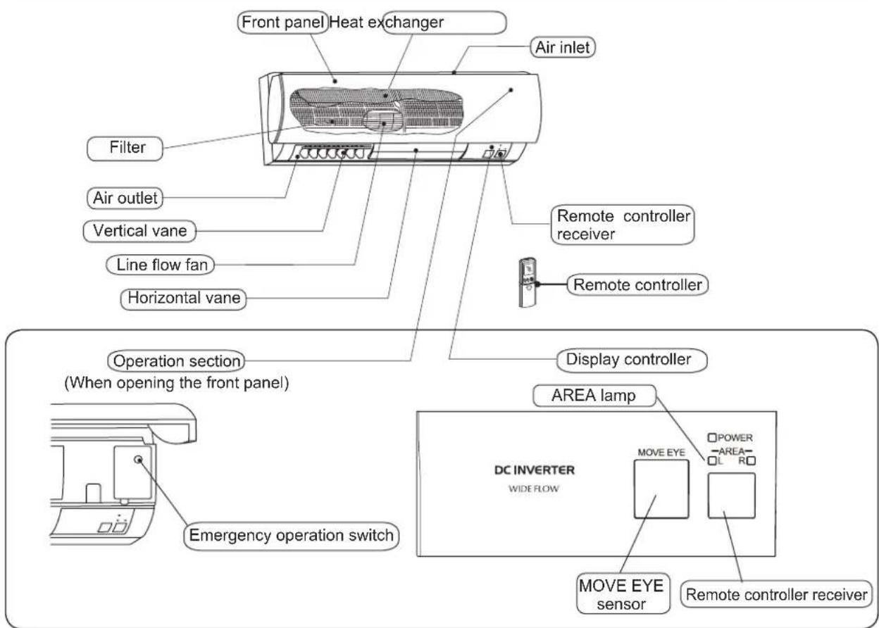
Indoor unit
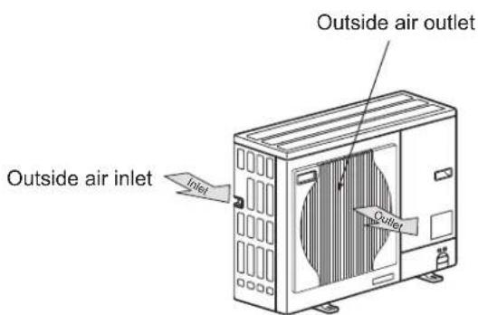
Outdoor unit
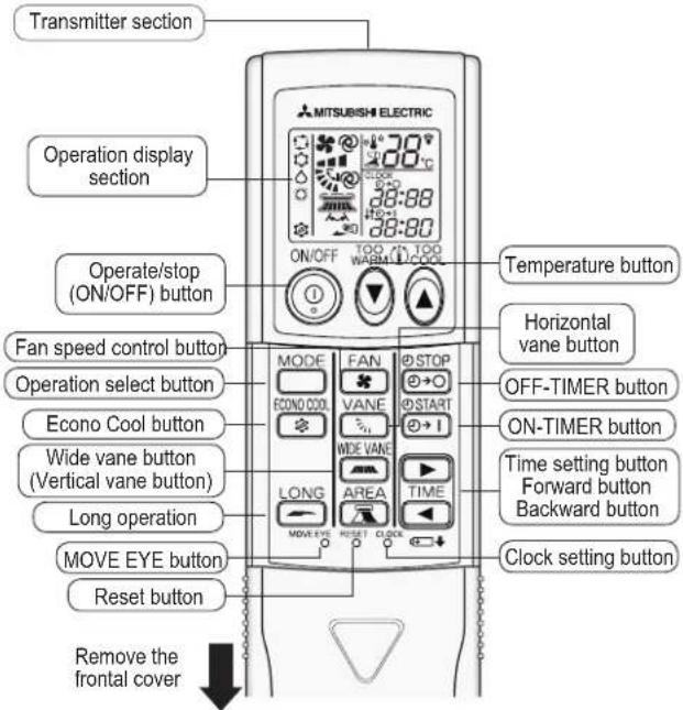
Remote controller
How to install battery and set current time
1 Remove the frontal cover and install batteries. Then, reinstall the cover. Insert the cathode of the batteries in the first. Check if the polarity is correct.
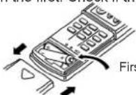
First, insert the negative electrode
2 Press the reset button. Use sharp thing to press it.
- If the reset button is not pressed, the remote controller can't work normally.
- Note that the pressing shall not be done forcibly.
3 Press the Clock setting button. Use something sharp at the end to press it.
4 Press (forward) and (backward) button (time setting button), set current time.
• Each press of the Forward button increases one minute; Each press of the Backward button decreases one minute.
- If you press and hold down the button for a long time, the set time will increase/decrease in ten minutes intervals.
5 Repress the Clock setting button and close the frontal cover.
Important setting
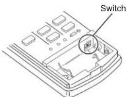
HOW TO SWITCH OVER
■ Be sure to set the slide switch inside the remote controller to an appropriate position in accordance with the installed position of the indoor unit. If the switch is not set correctly, the air conditioner may not function properly.
| Area Left Center Right | |||
| Position of the slide switch | |||
| Display on the remote controller |
Where is the indoor unit installed in the room?
Installed at left, (The distance is not more than 50cm.) (Left) (Center) Installed at right, (The distance is not more than 50cm.) (Right)
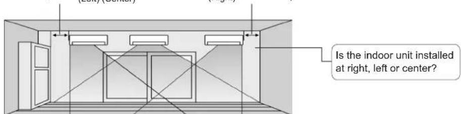
* If the indoor unit is installed more than 50 cm away from the side walls, cabinets or other nearby objects, set the slide switch to the "center" position.
Preparation before operation
How to use the remote controller
- The signal can travel up to 6 meters (in a straight line) away from the frontal face of indoor unit.
- At the time of pressing the button, the indoor unit beeps once or twice to confirm the signal received. If the unit doesn't beep, press the button again.
- Use the remote controller carefully. If it falls down to the ground, is thrown or soaked in water, malfunction may result.
Battery
■Standard for replacing battery
Two new alkaline batteries (No.7, LR03) shall be replaced in the following condition:
- The indoor unit has no response to the signal sent from the remote controller.
- The display of the remote controller becomes light. Please don't use manganese battery, or the remote controller will be in failure.
- The lifespan of a alkaline battery is about one year. However, it's recommended to consider the expiration date (year/month) at the bottom of a battery. If the expiration date draws near, the battery should be replaced as soon as possible.
- In order to avoid fluid leakage, please take out the battery if it is not used for a long time.

Note:
If the battery fluid splashes against skin or clothes, please wash them with clear water carefully. If the battery fluid splashes into eyes, please wash them with clear water immediately and see a doctor.
- Don't use rechargeable battery.
- Two batteries shall be of the same type.
- Obsolete batteries shall be disposed of properly.
Auto-restart function
The unit is set with auto-restart function, which is set to OFF when the unit leaves factory. If you want to use the function, contact the technical service center.
Auto-restart function refers
to the following contents:...
When the indoor unit is controlled by the remote controller, the unit will automatically remember the operation mode, set temperature and fan speed. If power cut or power-off occurs during operation, Auto-restart function will enable the unit to start automatically and operate in the previous mode set by the remote controller after power-on.
Indoor unit
■Insert the power plug in the socket. Turn the power switch to ON position.
Warning
Confirm a firm connection by removing the dust on the power plug. Fire or electric shock may result from a plug with dust or socket in failure.
When the remote controller can't be used (emergency operation)
When the dry batteries in the remote controller are exhausted, or when the remote controller is in failure, you can use the emergency operation button on the unit to control the operation.
1
Press the emergency operation button.
- Each press of the button enables the unit to change operation mode following the order of Cooling→Heating→Stop.
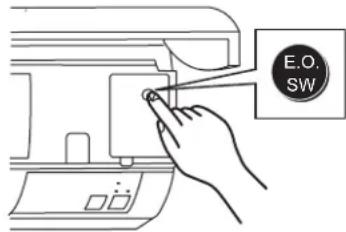
- The operation mode is indicated by the AREA lamp on the indoor unit as follows:
| Emergency cooling | AREA | Operation Indicator | |
| ■ L Light | R □ Black out | ||
| Emergency heating | AREA | □ L Black out | R □ Light |
| Stop | AREA | □ L Black out | R □ Black out |
NOTE:
This displayed in emergency operation.
- The operation is described as follows: The operation is described as follows. In the first 30 minutes, the unit only operates continuously without impact from room temperature. The fan speed is constant. After 30-minute operation, the unit status is as follows:
| Operation mode | Cooling | Heating |
| Set temperature | 24°C | 24°C |
| Fan speed | Medium | Medium |
| Horizontal (vane) | Automatic | Automatic |
| Vertical vane | Front | Front |
2
To stop the Emergency operation, press the Emergency operation switch.
- Each press of the button enables the unit to change operation mode following the order of Cooling → Heating → Stop. → Stop.Stop.
"I FEEL..." Auto Operation
In the mode of "☐ I FEEL..." Auto Operation, one press of the button enables the room condition to reach optimum status.
When starting "I FEEL..." Auto Operation
■Press button.
At the time of displaying ☐ (Auto Operation), the air conditioner is automatically controlled to the optimum temperature.
When stopping
■Press button
About 15 minutes after the start of operation:
If you feel too hot:
■Press button to decrease the temperature.
Each press of the button decreases the temperature by about 1°C
If you feel too cold:
■Press ▲button to increase the temperature.
Each press of the button increases the temperature by about 1°C.
At the time of not displaying ☐(Auto Operation), please press MODE button to set Auto Operation mode. Each press of the button enables the unit to change operation mode following the order of ☐(Auto Operation) → ⚙ (Cooling) → △(Dry)→ ⏻(Heating).
Auto Operation mode
Auto Operation
The operation mode is automatically set to Cooling, Dry or heating based on the room temperature at initial operation. However, if the unit operates again within 2 hours after stopping, it will operate following the same set points with the previous operation. Once the set points are set, the operation will not vary with the room temperature. If you don't like the set points, you can press MODE button, then select proper set points.
Set points for "I FEEL..." Auto Operation
| Room temperature at initial operation | Operation mode | Target temperature (initial status) |
| Over 25°C | Cooling | About 24°C |
| Below 25°C | Dry | — |
| Below 23°C | Heating | About 26°C |
Note:
Cooling: When the room temperature is 2^ C higher than the set temperature, the latter will not change. Because the air conditioner is operating to reach the target (set point) temperature. Meanwhile, please wait for room temperature to decrease to the temperature around the set one ( +2^ C), then you can change the set temperature. Heating: When the room temperature is 2^ C lower than the set temperature, the latter will not change. Because the air conditioner is operating to reach the target (set point) temperature. Meanwhile, please wait for room temperature to increase to the temperature around the set one ( +2^ C), then you can change the set temperature.
Manual operation (Cooling, Dry, Heating)
When selecting operation mode (Cooling, dry, heating)
1
Press @button.
2
Press MODE button to select operation mode.
Each press of the button enables the unit to change operation mode following the order of ☐ (Auto Operation) → ⚙ (Cooling) → △(Dry)→ ⏰ (Heating).
When stopping
■Press button.
Set the operation mode. Once you press button, the air conditioner will operate following the set mode.
■When changing set temperature:
- At the time of decreasing temperature, press ⬇ button. Each press of the button decreases about 1°C .
- At the time of increasing temperature, press 📄 button. Each press of the button increases about 1°C.
When operating in Dry mode
- Unable to control temperature (temperature setup)
- Operate at the temperature slightly lower than room temperature.
Note:
- When the environmental temperature is too high, room temperature may not reach the set temperature due to excessive load in cooling operation.
- Heating principle for heat pump type air conditioner: The unit absorbs heat from outdoor air by refrigerant cycling, transmit the heat inside the room and heat up the air in the room. The heating capacity decreases with the temperature drop of outdoor temperature.
- If outdoor temperature becomes extremely low, please use the unit together with other heating equipment.
Notice for using air conditioner
Cooling:
How to make an efficient cooling operation
- Close the windows tightly, put down the curtain, and reduce sunshine amount.
- Stick commercially available heat shielding film to the windows for reduction of sunshine heat.
- The outdoor unit shall be installed in a place where the sunshine is absent.
Heating:
The warmth beneficial to health mainly depends on the temperature difference between indoor and outdoor environment!
The set temperature for heating operation shall not differ from outdoor temperature excessively. Although it varies with the region, generally speaking, the set temperature can be set to 20^ C\~ 24^ C.
Dry:
A humidity of 70% is a divergence point at which people feel comfortable.
When people feel sultry, it indicates that there is a great number of vapor in the air, that is to say, the humidity is high. Humidity is concerned with temperature and airflow. Generally speaking, a humidity of 60%\~75% in summer and that of 55%\~70% in winter shall be the ideal condition at which people feel most comfortable.
MOVE EYE CONTROL OPERATION...Sensible temperature
• The proceed of the unit's temperature control is a general temperature control proceed, that accord to the temperature of wall, floor and room measured by MOVE EYE sensors (MOVE EYE control operation).
- When cancel MOVE EYE control, the general temperature control proceed will instead.
Starting MOVE EYE control

MOVE EYE control operation is activated when MOVE EYE button is pressed with a thin stick in manual COOL mode.
Note:
MOVE EYE control operation is activated when the remote controller is first used following replacement of the batteries or resetting of the remote controller.
Cancelling MOVE EYE control

MOVE EYE control operation is cancelled when MOVE EYE button is pressed with a thin stick once again.
Note:
If the conditioner is turned OFF without cancelling MOVE EYE control operation, MOVE EYE control operation is activated the next time the air conditioner is turned ON.
MOVE EYE control operation
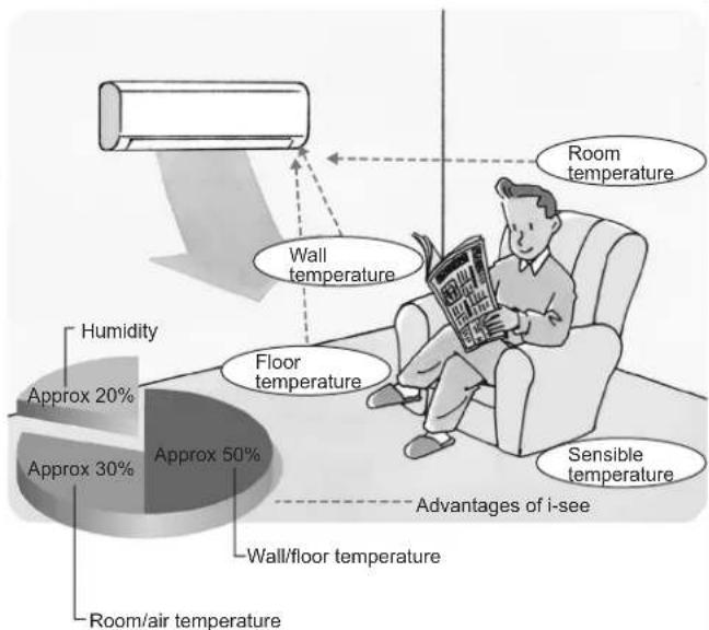
The sensors constantly measure the room and floor/wall temperatures to automatically adjust to the set temperature by estimating the temperature actually perceived by a person inside the room ("sensible temperature").
Advantages:
- The air inside the room is conditioned quickly to a comfortable condition.
- The room will not become too cold or hot even when the air conditioner is kept on for a long period.
pie
| Temperature Type | Percentage (%) | | :--- | :--- | | Room temperature | 50 | | Wall temperature | 20 | | Floor temperature | 30 | | Humidity | 20 | | Approx air temperature | 30 | | Wall/floor temperature | 50 | | Sensible temperature | 10 | Advantages of i-seeMOVE EYE sensor
- When AREA setting is not activated, the sensing range of MOVE EYE Sensor differs depending on the installation location of the air-conditioner.
| Installation opsition | Installation at left | Installation at center | Installation at right |
| Image of sensing range | |||
| Driection of sensor | Left Center Right | ||
Refer to the description for slide switch setting (Page 4).
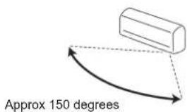
- This setting of temperature measurement is mnemonic (previous status setting), this temperature sensor in full range may detect the radiant temperature of floor / wall in the 150^ range (one of three installation spaces, left / center / right); therefore, the detected temperature may be different, because the standard temperature (near measured value by market-sold thermometer) is classified according to the temperature near the room or ground and/or wall.
• After maintenance or repair, please install the front frame components properly so as to detect the radiant temperature of floor / wall.
AREA setting
When AREA have been set, horizontal air flow (Horizontal Vane) can adjust automatically according to the temperature measure from the wall and floor.
AREA setting
- Press AREA button.
• Each time the button is pressed, the area is changed in sequence:
Auto Left → Right → Cancel (Recover to previous setting) Cancel MOVE EYE Sensor moves intermittently, measuring the floor and wall temperature.
Note:
- AREA setting is only available during MOVE EYE control operation. (Refer to page 8)
- If AREA setting is canceled, the vertical vane returns to the previously set position before AREA setting.
- The horizontal air flow direction (vertical vane), can not be set during AREA setting.
| Moving of horizontal air flow direction | ·If AREA setting is set to AUTO in heating operation, the indoor unit automatically delivers warm air to the area where the floor/wall temperature is the lowest in the room.·If AREA setting is set to AUTO in cooling operation, the indoor unit automatically delivers cool air to the area where the floor/wall temperature is the highest in the room.Ex.) In heating operation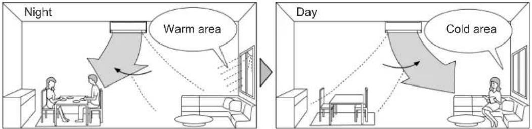 The indoor unit delivers warm air detecting the cold area in the room. The indoor unit delivers warm air detecting the cold area in the room. |
| Indoor unit display | Indication of AREA settingLight Black out Black out Light |
| NOTE | ·The horizontal air flow direction changes if MOVE EYE Sensor detects approx.3 temperature difference.·In AUTO of AREA setting, both right and left lamps are lighted when the room is evenly air-conditioned.Light Light |
Cancelling AREA setting
■Press AREA button (select cancel)
- AREA setting is cancelled when WIDE VANE button is pressed.
Indoor unit installation location and air-conditioning area.

- Be sure to set the side switch inside the remote controller to an appropriate position in accordance with the installed position of the indoor unit. If the switch is not set correctly, the air conditioner may not function properly. (Refer to Page 4)
AREA setting
| AREA setting | To air-condition mainly the left area of the room. | To air-condition the entire room. The horizontal air flow direction and indoor unit display are switched according to the room temperature (floor/wall). | To air-condition mainly the right area of the room. | |
| Remote controller button | Press AREA button to select LEFT | Press AREA button to select AUTO | Press AREA button to select RIGHT | |
| Control range of horizontal air flow direction. The vertical air flow direction conforms to the setting on the remote controller (The horizontal air flow direction is controlled in this range.) | Installed at center | 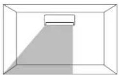 | 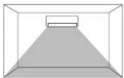 | 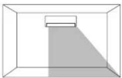 |
| Installed at left | 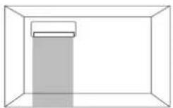 | 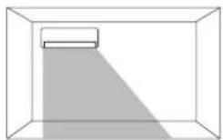 | 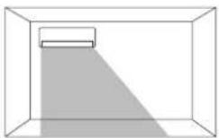 | |
| Installed at right | 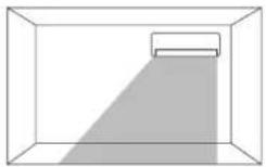 | 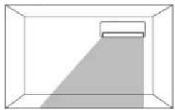 | 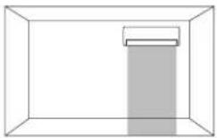 | |
| Indoor unit display | AREA | AREA L R□ | AREA L R□ or L R□ or □L R□ | AREA □L R□ |
Airflow velocity and direction adjustment
■To change the airflow velocity, press the ✕ button. ■(Lo)→ ■(Me)→ ■(Hi)→ 📋 (Auto).
How to select fan speed:
Principle of the air conditioner: The greater the air volume, the more effective the energy saving, and the higher the noise. The air outlet temperature increases at cooling mode and decreases at heating mode. Therefore, selecting the fan speed of Lo enables you to get a quiet environment for rest. Selecting the fan speed of Hi or SHi enables you to get an effective energy saving.
VANE
■At the time of changing vertical airflow direction, press button.
Each press of the button enables the unit to change vertical airflow direction following the order of

Airflow with swing
Swing operation enables the airflow to reach all corners of a room.
Recommended scope for vertical airflow direction.
Usually, please turn to (Auto).
Turn to position (2) in cooling or dry mode.
Turn to position (3)\~ (5) in heating mode.
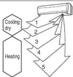
flowchart
graph TD
    A["Cooling dry"] --> B["1"]
    C["Heating"] --> D["2"]
    D --> E["3"]
    E --> F["4"]
    F --> G["5"]
Airflow velocity and direction adjustment
Movement of horizontal vane
| Cooling/Dry | Heating | |
| Auto | 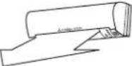 Horizontal positionThe vane moves to the horizontal position after stopping swing.Note:The airflow is higher than position 1. Horizontal positionThe vane moves to the horizontal position after stopping swing.Note:The airflow is higher than position 1. | 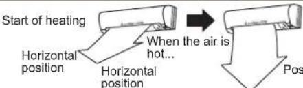 ition 4After the air conditioner starts to operate, the vane stops in horizontal position.Once the temperature of the airflow from indoor unit is enough high, the vane will move to Set position 4.Once the air conditioner starts to operate, fan speed increases with the temperature rise of airflow from the indoor unit and until the set speed. ition 4After the air conditioner starts to operate, the vane stops in horizontal position.Once the temperature of the airflow from indoor unit is enough high, the vane will move to Set position 4.Once the air conditioner starts to operate, fan speed increases with the temperature rise of airflow from the indoor unit and until the set speed. |
| ManualSwing | 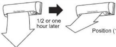 1) or (2)The airflow direction is set to position (2), (3) or (4), (5)When the air conditioner operates for about one hour, the vane moves to position (1) or (2) automatically. Press the button Vane on the remote controller to change the airflow direction back to original set point. 1) or (2)The airflow direction is set to position (2), (3) or (4), (5)When the air conditioner operates for about one hour, the vane moves to position (1) or (2) automatically. Press the button Vane on the remote controller to change the airflow direction back to original set point. | Start of heatingHorizontal posit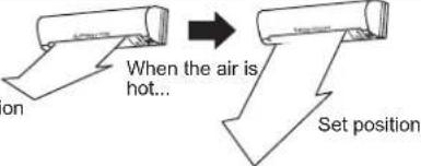 After the air conditioner starts to operate, the vane stops in horizontal position.Once the temperature of the airflow from indoor unit is enough high, the vane will move to Set position.Once the air conditioner starts to operate, fan speed increases with the temperature rise of airflow from the indoor unit and until the set speed. After the air conditioner starts to operate, the vane stops in horizontal position.Once the temperature of the airflow from indoor unit is enough high, the vane will move to Set position.Once the air conditioner starts to operate, fan speed increases with the temperature rise of airflow from the indoor unit and until the set speed. |
| (25+7) | The vane moves intermittently between position (1) and (5). The vane stays at position (1) and (5) for a moment.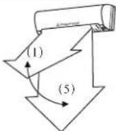 | The vane moves intermittently between position (2) and (5). The vane stays at position (2) and (5) for a moment.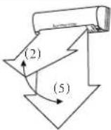 |
Note:
- Adjust the airflow direction by the remote controller. Moving the vertical vane or horizontal vane by hand may cause failure.
- When the operation mode changes to mode "auto", the horizontal vane changes to different positions automatically mentioned above.
■ Press button ▶ change airflow direction (left/right)
Each press of the button enables the unit to change the vertical vane angle following the order of:

flowchart
graph LR
    A["Top Top"] --> B["Top Left"]
    B --> C["Top Right"]
    C --> D["Top Right (Swing)"]
    D --> E["Top Bottom"]
    E --> F["Bottom Right"]
Blow with swing.
Blow with swing enables the airflow to reach each corner of the room.
Long operation
Perform the following operations while the unit is operating.


Press button.
The fan speed increase.
When the fan speed is set to AUTO, the fan speed is higher than a fan speed determined by the room temperature and the set temperature.
In addition, the HORIZONTAL VANE moves to the position for LONG mode.
Mechanism of the LONG operation
In the following example, the VERTICAL VANE is sent to front).
COOLING/DRY
HEATING
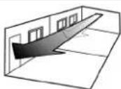
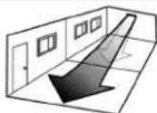
Fan speed: Higher
Solid arrow: When the LONG mode is used Dotted arrow: When the LONG mode is not used
• To Release the LONG mode.
■ Press the button again.
Note
■ LONG mode is also released in the following ways.
- By pressing the VANE button
- By pressing the button (only during COOL mode)
Even when the LONG mode is being used, the air may not reach a long distance due to the installation location of the air conditioner.
In this case, press the FAN button to set the fan speed to 📁), and then press the LONG button.
MODE FAN WIDE and buttons temperature buttons and the ON/OFF timer are available.
Econo cool operation
Enable this mode to enjoy healthy, comfortable and power-saving cooling operation.
Please operate as follows in manual cooling mode
Press button.
Select the air conditioner operating in ⚙ (Econo Cool) control mode, which controls the horizontal vane to swing periodically and automatically according to the outlet temperature.
Moreover, the set temperature increases by 2^ C automatically based on cooling operation.
When quitting Econo Cool operation
■ Press button again.

- In Econo Cool operation, press button or change operation mode to quit Econo Cool button.
- Airflow speed button FAN, Extreme Hot or Extreme Cold button and Timing ON/OFF button can be used continuously.
- What is Econo Cool?
Swinging airflow (variable flow) feels cooler than constant airflow, therefore, even if the set temperature is set to a higher one by 2°C you can feel comfortable and power is saved.
Timer operation (ON-Timer and OFF-Timer)
You can preset the air conditioner to ON-Timer and OFF -Timer at the time of sleeping, going home or getting up.
How to set ON-Timer

Press button.
Press ON-Timer button "@+" the figure flashes.

Set time for the timer by pressing Time button ▶ (increase) and ▶ (decrease).
Each press of button ▶ decreases the set time in 10 minutes intervals and each press of button ▶ decreases the set time in 10 minutes intervals.
QUIT ON-Timer

Press 📋 START button.
Combination of ON-Timer and OFF-Timer
Combine ON-Timer with OFF -Timer. The unit will operate first at the earlier set time.
(The mark "↑ ↓" shows operation order of timer.)
- If the current time is not set, timer operation will be disabled.
Note:
If main power supply is switched off or power failure occurs during timer operation, timer setting will be canceled.
How to set OFF-Timer

Press STOP button.

Press OFF-Timer button ☐ stop the figure flashes. Set time for the timer by pressing Time button ▶ (increase) and ▶ decrease). Each press of button ▶ increases the set time in 10 minutes intervals and each press of button ▶ decreases the set time in 10 minutes intervals.
Quit OFF-Timer

Press STOP button.
When the air conditioner is not used for a long time
Not used for a long time

Enable the fan to run for 3\~4 hours so as to dry the inside of the air conditioner.
- Before fan operation, set to Cooling operation mode and select highest set temperature.

Switch off the power supply.


Warning
Be sure to switch off the power supply when the air conditioner is not used for a long time.
Fire may result from possible dust deposit.

Take out the batteries in the remote controller.

Note:
When the remote controller is not used for a long time, be sure to take out all batteries in the remote controller to avoid fluid leakage.
To be used again

Clean the filter and return it to the unit. (Refer to page 15)

Be sure to confirm whether the air inlets and air outlets of indoor and outdoor units are covered.

Confirm whether the earth wire is connected firmly.

Warning
Must be grounded.
The earthing wire should not be connected to gas pipe, tap water pipe, lightning conductor and telephone line. If you don't connect the earthing wire as required, electric shock may result.
Maintenance
Before cleaning

Switch off the power supply.


Warning
When cleaning the unit, you have to stop unit operation by switching off the power supply. Because fan blades in high-speed rotation may hurt you.
Cleaning for indoor unit

Clean with soft dry cloth.
- If there is distinct smear, use a piece of cloth soaked with neutral detergent to clean the unit, and wipe off the water with soft dry cloth.
- Never use gasoline, volatile oil, friction powder or disinfectant. Otherwise, they may damage the unit.
- Never use market-sold detergent that is marked with "No use for cleaning of metal products" to clean the panel of indoor unit.
Filter Cleaning
Filter Cleaning (Cleaning is done once two weeks)
1 Pull out the filter slightly.
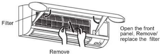

Note
During disassembly of the filter, take care not to touch the metallic part of the indoor unit, as you may be scratched.
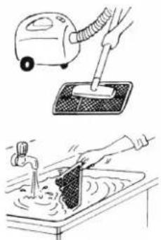
2 Use a cleaner to clean or use water to wash.
- Don't clean the filter with brush or hard sponge, otherwise, the filter will be distorted.
- If the filter is too dirty, use warm solution mixed with neutral detergent to wash the deodorizing filter.
- Don't use hot water (about over 50°C) to wash the filter to avoid distortion.
natural_image
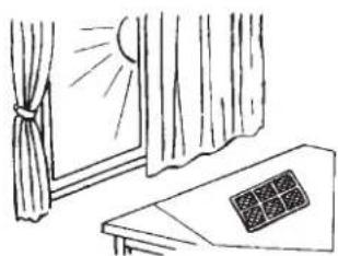
Illustration showing a hand using a vacuum cleaner to clean water, with another hand pouring liquid into a container (no text or symbols present)3 After washing with water, the filter can't be used until it is dried.
- Don't dry the filter under sunshine or with fire.
natural_image
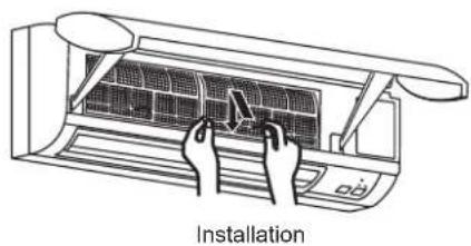
Simple line drawing of a window with curtains and a window with a sun, no text or symbols present.4 Installing the filter.
natural_image
Line drawing of an air conditioner unit with hands installing or adjusting the grille (no text or symbols)Please check the following items before connecting a serviceman
| Is there a failure? | Check point |
| The air conditioner can't operate. | • Is the power supply turned on?• Is the fuse blown?• Is ON-Timer set?(Page 14) |
| The horizontal vane can't operate. | • Are the horizontal vane and vertical vane installed in the indoor unit correctly?(Page 19)• Is the protective screening of the fan distorted? |
| Indoor cooling is not enough. | • Is the temperature setting correct?(Page 7)• Is the filter clean?(Page 15)• Is the indoor unit fan clean?(Page 19)• Is the air inlet or air outlet of the indoor or outdoor unit covered?• Are the doors and windows in room opened? |
| The indoor unit gives off odor. | • Is the filter clean?(Page 15)• Is the indoor unit fan clean?(Page 19) |
| Is there a failure? | Check point |
| The remote controller has no message to display or darkens. The indoor unit has no response to the signal from the remote controller. | Are batteries exhausted?(Page 5)Is the polarity of a battery placed correctly?(Page 5)Are buttons on the remote controller of other electric appliance pressed? |
| If the air conditioner can't still operate after the above items have been checked, please stop using the machine and contact the specialty shop or technical service center for help. |
Please pay attention to the following condition before asking a serviceman for repair.
- In a room decorated with electronic fluorescent lamp, the signal from the remote controller may be unacceptable.
- In circumstances with weak radio wave, the air conditioner may disturb the signal acceptance of broadcast or TV, thus, the affected equipment may need a magnifier.
- When thunder appears, you have to stop operation and remove power plug or turn off the power supply. Otherwise, there is a risk of damaging the electrical part in the air conditioner.
When you think trouble occurs
| Is there a failure? | Answer (it's normal) |
| The air conditioner can't operate within 3 minutes after you restart the machine. | • In accordance with the microcomputer's display, it means the protection of the air conditioner, please wait. |
| A crack is heard. | • The noise results from the expansion/shrinkage of the front panel due to temperature change. |
| The air out of the indoor unit has an odor smell. | • The air conditioner may absorb the peculiar smells from wall, carpet, furniture and clothes, then mix them with air for blowout. |
| Voice similar to current is heard. | • This is a voice from refrigerant flowing inside the air conditioner.• This is a voice from the flowing of condensed water drop inside the heat exchanger.• This is a voice from thaw of the heat exchanger. |
| Voice similar to air bubble is heard. | • This is a voice from the ejection of water flowing inside the drainage hose when the outdoor air is absorbed in the hose and when a soot absorption machine or a vent fan is activated. If the outside airflow is strong and blown into the drainage hose, you can hear the voice too. |
| Fog is blown out from the indoor unit outlet during operation. | • The fog results from quick condensation between moisture in the air and cold airflow from indoor unit outlet. |
| Snapping can be heard from indoor unit. | • This is a voice from the switching (ON and OFF) of compressor or fan. |
| Hiss can be heard from indoor unit. | • This is a voice in which the air conditioner starts or stops refrigerant flowing. |
| Is there a failure? | Answer (it's normal) |
| The horizontal vane and vertical vane pause to swing and then start to swing again. | The condition appears so that normal blowing with swing is enabled for the horizontal vane and vertical vane. |
| White mist from the outdoor unit. | In heating operation, the steam from thawing operation looks like white mist. |
| Air does not flow out quickly in the heating operation. | Please wait as the conditioner is operating to blow arm air. |
| The operation is stopped for about 10 minutes in the heating operation. | Defrosting of the outdoor unit is being done (Defrosting operation). Since this is completed within 10 minutes, please wait. (When the external temperature is too low and humidity is too high, frost is formed). |
| The room is not cooled or heated sufficiently. | The cooling load is high, because the exhaust fan or stove is in use. So the cooling capacity is not enough.The cooling or heating capacity is not enough because the outdoor temperature is too high or too low. |
| The airflow direction changes during operation. The remote controller can't adjust the movement of the horizontal vane. | When the air conditioner operates in cooling mode, if the air is blown downwards for one hour, the airflow direction is set to (1) or (2) automatically, which is to prevent condensed water drop from dropping.In the heating operation, if the output air temperature is too low or when defrosting is done, the horizontal vane position is automatically set to horizontal. |
| Water leaks from the outdoor unit | During the cooling operation, pipe connector sections are cool and this causes water condensed.Water or water vapor created by the defrosting operation is connected.Water adhering to the heat exchanger during heat operation drips. |
Removal and inspection
Check and repair
■ The performance of the air conditioner decreases due to long-term service and internal dirt.
■ Odor may result from using condition, or poor drainage of condensed water may result from dust deposit.
The check and repair are different from common ones. You'd better ask for special technical service. Please contact the specialty shop or technical service center for help.
Operation noise should be also considered.
- Don't place articles at the outlets of outdoor unit. For the placement will reduce the efficiency and increase noise in operation.
■ If there is abnormality in operation, please contact the specialty shop or technical service center for help.
When you want to remove the machine
■ When removing and reinstalling the air conditioner due to room enlargement or relocation, please ask for special technical service.
Waring
Don't reapair or remove the air conditioner by yourself. Maloperation may cause fire, electric shock, injury by unit drop and water leakage. If the air is mixed in the refrigerant, pressure may increase to lead to breakage. Thus, please contact the specialty shop or technical service center for help.
Safety precautions for Installation
1. For the sake of safety, please pay attention to the following safety precautions

Warning
Users are not allowed to install the machine by themselves.
- Improper installation may cause fire, electric shock, water leakage or injury from machine falling. Please contact the specialty shop or technical service center for help.
The machine should be installed in a place which can support its weight.
- If the machine is installed in a place which is not solid enough, there will be a risk of injury from machine falling.
Cables between indoor and outdoor unit shall be connected properly as specified, and connecting terminals for the cables be fixed firmly without being affected by external force.
- Poor connection or fixture may cause fire.
Installation shall be implemented properly based on installation instructions
Improper installation may cause fire, electric shock, water leakage or injury from machine falling.
Please ventilate room in the event of refrigerant leakage during installation.
- Exposure of refrigerant to open flame can produce toxic gas.
When installing or servicing the unit, use appropriate protective equipment and tools for safety.
- Failure to do so could cause injury.

Warning
In the event of installation or removing, any substance other than refrigerant shouldn't be mixed into the refrigerant circuit.
- If air is mixed in the circuit, system pressure will increase to cause breakage.
Don't fill other refrigerant than specified while installing or moving the unit.
- If so, it may become the cause of problems such as malfunction, false action and mechanical fault and possibly leads to major safety accidents in some cases.
When pumping down the refrigerant, stop the compressor before disconnecting the refrigerant pipes.
- If the refrigerant pipes are disconnected while the compressor is running and the stop valve is open, air could be drawn in and the pressure in the refrigeration cycle could become abnormally high. This could cause the pipes to burst or injury.
When installing the unit, securely connect the refrigerant pipes before starting the compressor.
- If the compressor is started before the refrigerant pipes are connected and when the stop valve is open, air could be drawn in and the pressure in the refrigeration cycle could become abnormally high. This could cause the pipes to burst or injury.
Electrical work should be performed according to installation instructions. Be sure to use special power supply of circuit.
- Fire or electric shock may result from insufficient capacity or incomplete construction for the power supply circuit.
Safety precautions for Installation

Warning
The electrical cover of indoor unit or the service board should be installed correctly.
- If the cover and the service board are not installed well, fire or electric shock may result due to entrance of water and dust.
Attached or specified parts should be used for installation construction.
- Improper parts may cause fire, electric shock, water leakage or injury from machine falling.
For the power supply circuit, connection in the middle section, extension of power cord or use of multi-cable socket are not suggested.
- Poor contact, poor insulation or overload may cause electric shock.
Grounding construction shall be done.
• The air conditioner socket shall be connected with special earth wire. Electric shock may result from no grounding or poor grounding.
- Don't connect the earth wire to gas pipe, tap water pipe, lightning rod or telephone earth wire.
Don't install the unit in a place where combustible gas may leak.
In case the combustible gas leaks and accumulates around the unit, explosion may result.
A leakage protector shall be installed.
- If the leakage protector has not been installed, an electric shock may result.
Be sure to implement drainage and piping construction in terms of installation instruction
- If there are improper drainage and piping construction or inclined indoor unit, furniture will be wet and contaminated by water drop from indoor unit.
The connection wire from the middle section of connection wire/signal connection line should not be adopted.
- Misoperation of the unit will occur, causing the unit not to operate normally.
Please install the unit in terms of national rules of wiring.
After installation construction, be sure to confirm whether there are positions in which refrigerant gas leakage occurs.
If the power cord is damaged, be sure to replace it with special power cord or with special components bought from manufacturer or service center.
Moreover, if you have no notion of something, contact the specialty shop for help.
2. Atention for R410A refrigerant systems
2-1 Using R410A refrigerant air conditioners

Caution
- Use C1220 copper phosphorus (for copper and copper alloy seamless pipes) to connect the refrigerant pipes. Make sure the insides of the pipes are clean and do not contain any harmful contaminants such as sulfuric compounds, oxidants, debris, or dust. Use pipes with the specified thickness.
- Use ester oil, ether oil, alkylbenzene oil (small amount) as the refrigeration oil applied to the flared sections. If mineral oil is mixed in the refrigeration oil, oil deterioration may result.
- Do not use refrigerant other than R410A refrigerant. If another refrigerant is used, the chlorine will cause the oil to deteriorate.
- Use the following tools specifically designed for use with r410a REFRIGERANT. The following tools are necessary to use R410A refrigerant. Contact your nearest dealer for any questions.
| Tools (for R410A) | |
| Gauge manifold | Flare tool |
| Change hose | Size adjustment gauge |
| Gas leak detector | Vacuum pump adapter |
| Torque wrench | Electronic refrigerant charging scale |
- Be sure to use the correct tools. If dust, debris, or moisture enters the refrigerant lines, refrigeration of deterioration may result.
- Do not use a charging cylinder. If a charging cylinder is used, the composition of the refrigerant will change and the efficiency will be lowered.
2-2 Precautions for devices that use R410A refrigerant

Caution
- When installing or moving the air conditioner, use only the specified refrigerant (R410A) to charge the refrigerant lines. Do not mix it with any other refrigerant and do not allow air to remain in the lines. Air enclosed in the lines can cause pressure peaks resulting in a rupture and other hazards.
| MSZ-WG20/25VA-H1 | |
| Liquid pipes | 9.52mm (Thickness 0.8mm) |
| Gas pipes | 15.88mm (Thickness 1.0mm) |
*Do not use pipes thinner than those specified above.
• Do not share the vacuum pump with R22 refrigerant systems.
Safety precautions for Installation
3. Selection of installation location
3-1 Indoor unit
- A place where inlet/outlet airflow shall not be obstructed.
- A place where blown cold air can reach each corner of the room.
- The maximum distance and maximum height difference between indoor and outdoor unit: Refer to Extreme Pipe Length.
- A solid wall where vibration can't occur.
- A place where direct sunlight is avoided.
- A place where drainage becomes easy.
- A place where the unit is 1 meter apart from radio and TV or 3 meters apart from antenna.(Otherwise, the TV image will be disturbed or noise may occur.)
- A place where the unit is far away from fluorescent or incandescent lamp(Otherwise, wireless remote controller may in maloperation).
- A place where it's easy to install and remove the air filter freely.
3-2 Outdoor unit
- A place with less influence from gale and heavy snow. If the unit is installed in a region of heavy snow, measures shall be taken for prevention of heavy snow(You are advised to install a covering or base frame).
- A place with good ventilation and less dust.
- A place with less rain or less direct sunlight.
- A place where operation noise or blown hot air can't bother neighbor.
- In order to reduce operation noise or vibration, you shall install the unit in a solid frame.
- A place where there is no leaked combustible gas.
- When installing the unit in a higher place, you have to fix the foot of the unit.
- Be sure to install the unit horizontally.
- Easy for maintenance and repair.
The installation location of the outdoor unit should be at least 3 m away from the antennas for TV sets, radios, etc. In areas where the reception is weak, provide greater space between the outdoor unit and the antenna of the affected device if operation of the air conditioner interferes with radio or TV reception.
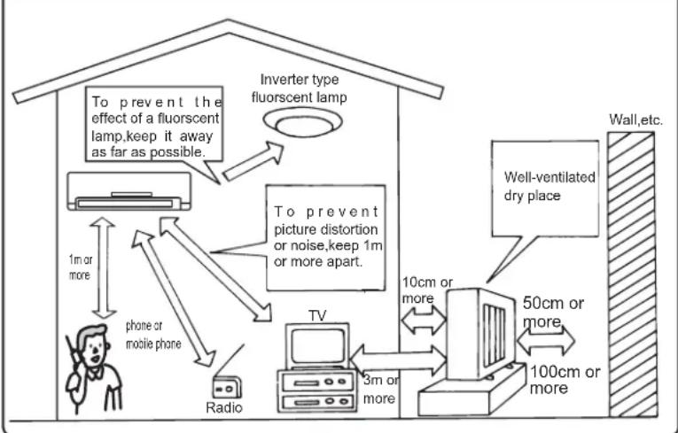
flowchart
graph TD
    A["Inverter type\nfluorescent lamp"] --> B["To prevent the effect of a fluorescent lamp, keep it away as far as possible."]
    B --> C["TV"]
    C --> D["Radio"]
    C --> E["phone or mobile phone"]
    E --> F["1m or more"]
    F --> G["TV"]
    G --> H["3m or more"]
    H --> I["TV"]
    I --> J["10cm or more"]
    J --> K["Well-ventilated dry place"]
    K --> L["50cm or more"]
    L --> M["100cm or more"]
    M --> N["Wall, etc."]
⚠ Notice
Don't install the air conditioner in the following places.
·A place where plenty of machine oil is used.
Seashore with a great deal of salt.
·A place where there are hot spring and sulfurized gas.
·A place where there is a problem with other environmental atmosphere
·A place where there are volatile, corrosive and combustible chemicals.
·A place where cranes and ships move.
1. Installation diagram and accessory
Packing list (Before installation, users are advised to verify the amount of parts based on the packing list)
| Part name Part name | Amout | ||||||
| Installation No. | Amout | Installation No. | |||||
| IndoorUnit | Indoor unit | 1 | OutdoorUnit | Outdoor unit | 1 | ||
| 1 | Mounting plate | 1 | A* | Indoor and outdoor connection cables | 1 | ||
| 2 | Screw 4×25 mm | 7 | Power line | 1 | |||
| 3 | Battery (No.7) | 2 | B* | Connection pipe (gas) | 1 | ||
| 4 | Remote controller | 1 | Connection pipe (liquid) | 1 | |||
| 5 | Felt strap | 1 | C* | Wall hole sleeve | 1 | ||
| Guarantee | 1 | D* | Wall hole cover | 1 | |||
| Operating andinstalling instructions | 1 | E* | Pipe strap | 1 | |||
| F* | Extension drainage hose | 1 | |||||
| G | Concentration drainage component | 1 | |||||
* This components need to be purchased.
Installation dimensions
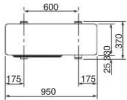
(Unit:mm)
Note:
(1) Don't use the drainage pipe connector and rubber stopper in cold areas. Failure may result from drainage freezing.
Steps for installing drainage pipe
(1) Select a drain hole in the base for draining and connect the drainage pipe connector to the hole.
(2) Block residual drain holes in the base with rubber stopper.
(3) Connect the drainage pipe to the connector. Keep the drainage pipe to tilt downsards to make a smooth draining.
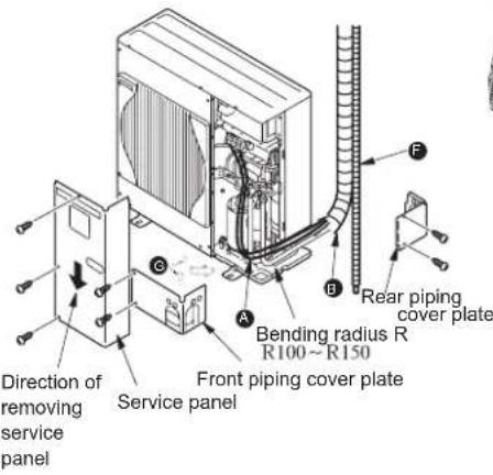
Flared joint
- The unit is equipped with flared joints at indoor/outdoor unit side. - As shown in the figure below, refrigerant pipe is used to connect indoor/outdoor unit.
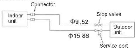
flowchart
graph LR
    A["Indoor unit"] --> B["Connector"]
    B --> C["Stop valve"]
    C --> D["Outdoor unit"]
    D --> E["Service port"]
    C --> F["Φ9.52"]
    D --> G["Φ15.88"]
| Limit | |
| Pipe length | 15m |
| Height difference | 5m |
| Amount of bends | 10pieces |
- Adjustment of refrigerant · · · If the pipe length exceeds the scope in the table below, refrigerant (R410A) should be supplemented. (Filling refrigerant to the outdoor unit with refrigerant shall be subject to the following pipe length.)
| Pipe length | Type | Dosage of refrigerant |
| Over 7 meters | MSZ (Inverter) | 30g×(pipe length (m)-7) |
- Note: Excessive extension of piping will cause cooling and heating capacity to decrease.
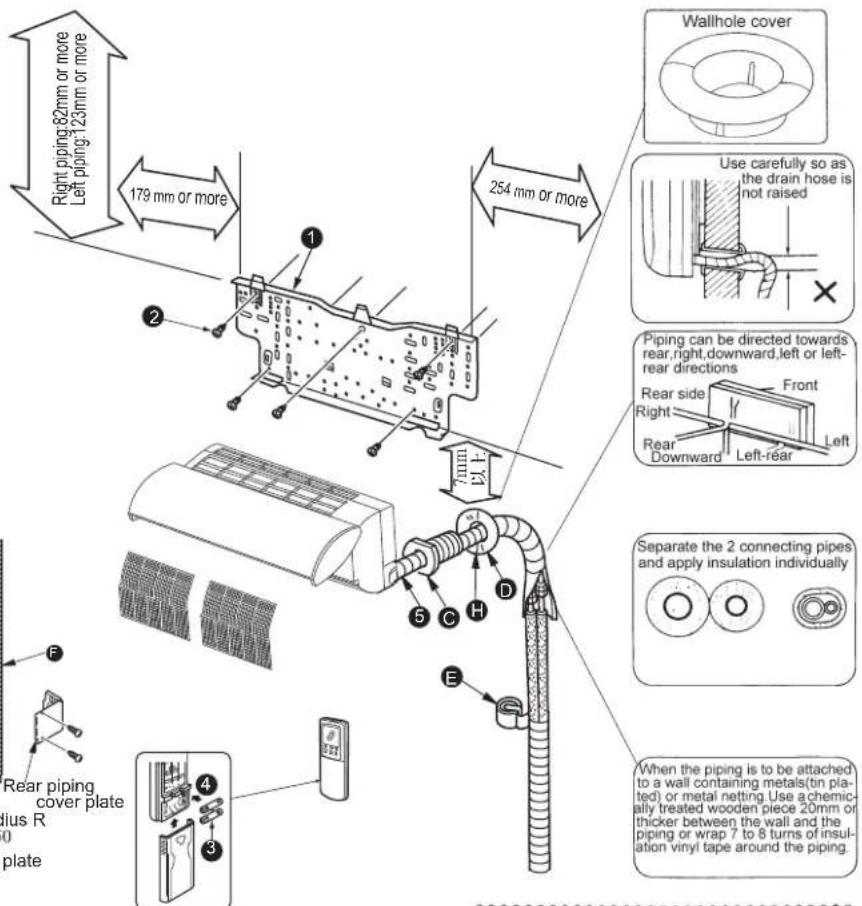
Units should be installed by licensed contractor according to local code requirement.
Installation instructions
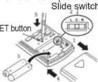
1-1 How to set slide switch (inside battery box of remote controller)
Details of slide switch
Details of slide switch
① Remove the front lid.
② Be sure to place the slide switch in right position inside the battery box of remote controller (identical to space position of indoor unit installation, according to requirement). Or else, this conditioner will not run under the optimum state (Refer to page 4).
NOTICE:
If the indoor unit has been installed more than 50cm away from the side walls, cabinets or other objects nearby, place this slide switch to the "center" position.
③ Insert two (AAA) 1.5V batteries into battery box.
④ Reattach the front lid.
⑤ Press the RESET button with a thin object (pen).
2. Installation for indoor unit
2-1 Fixing of mounting plate
Look for a structural part (such as a pole) so that you are sure to fix the mounting panel horizontally. If the indoor unit declines, the furniture will be wet and contaminated by water drop from the unit.
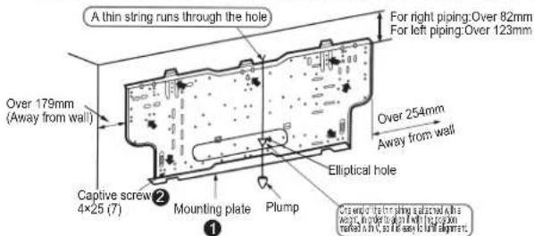
To prevent the slight vibration of mounting plate, holes marked with should be fixed, and parts marked with should be also fixed as possible.
- If user needs to break through the middle elliptical hole in the back of mounting plate when installing the unit, please affix the scratchproof plastic adhesive tape on the end face of this hole (this adhesive tape shall be provided by user). - When using expansion screws buried into cement wall, you shall use elliptical holes of 11 × 20 and 11 × 26 with 45cm apart from each other to fix the mounting plate. If the expansion screw is too long, use short screws sold in market.
2-2 Drilling hole in the wall
① Confirm the hole position in wall.
② Drill a hole (diameter: 75mm) tilting slightly downwards from inside to outside.
③ Insert Wall-hole sleeve Ⓒ in the Wall-hole.
④ Embed the putty Ⓗ between Wall-hole and sleeve.
Confirm the hole position
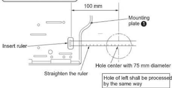
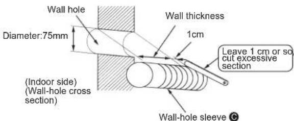
Always use the wall hole sleeve Ⓐ, which prevents the connection wires between indoor and outdoor unit from contacting the metallic parts inside wall and rodent pest from occurring.
2-3 Specifications for power supply and connection wires
- This unit is powered outdoors.
- Use special cables for air conditioner.
Specifications of connection wires between indoor and outdoor unit
YZW type cable with the section area of 1.5 mm ^4
- Lead out a power cord from the left or right bottom of the indoor unit.

Warning
- Each air conditioner should be equipped with special power supply line. Power supply specification should accord with national regulations and be installed with independent switch. - It is prohibited to cut off the power cord and connect it to other lines, or else fire may occur.
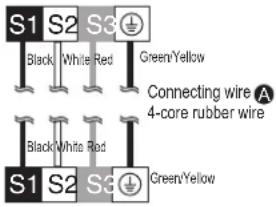
2-4 Connection of indoor/outdoor wires
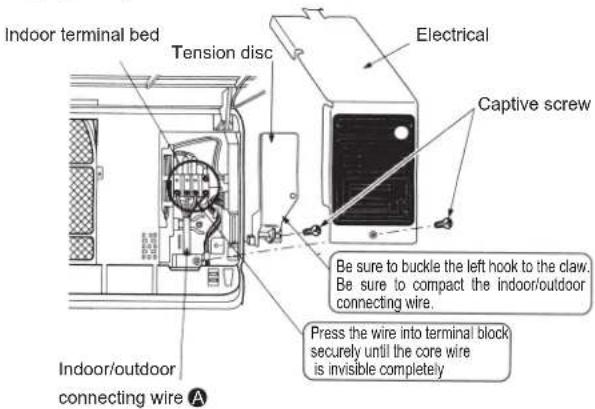
Connect indoor/outdoor lead wire without removing front frame.
① Open the front panel.
② Unscrew the captive screws in electrical cover to remove it.
③ Unscrew the captive screws in cable clip to remove it.
④ Pass the connecting wire of indoor and outdoor units to the front side from the back of the indoor unit, then process the wire end and then fix it to the terminal board.
⑤ Place the wire clip and the electrical cover in its home position securely and tighten the captive screws.
(Figure 1)
Warning
- Cables between indoor and outdoor unit shall be connected in good order using specified cables and connecting terminals be fixed well without being affected by external force. Fire may result from poor connection or fixture.
- Electrical cover shall be fixed well, otherwise, fire or electric may result from entry of dust and moisture.
- Be sure not to make wrong connection.
•Electric shock may result from wrong grounding.
Note
•Tighten terminal screws to avoid looseness.
•After tightening of the screws, pull the wires slightly to verify whether they are tightened.
•The air conditioner can operate correctly only when the wires are connected correctly to the terminal block.
⚠ Warning
- Wires between indoor and outdoor terminal block shall be marked with number for corresponding connection.
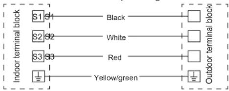
flowchart
graph LR
    S1["S1"] --> Black["Black"]
    S2["S2"] --> White["White"]
    S3["S3"] --> Red["Red"]
    S3["S3"] --> YellowGreen["Yellow/green"]
    Black --> Outdoor["Outdoor terminal block"]
    White --> Outdoor
    Red --> Outdoor
    YellowGreen --> Outdoor
MSZ model
Frequency conversion model
Loose the terminal screws
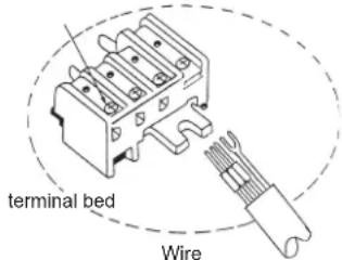
Indoor terminal bed
Outdoor terminal bed
Warning
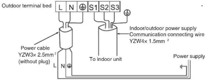
- Neutral line, live line and earthing wire inside power socket shall be connected as shown in figure reliably without wrong connection and internal short circuit.
- Fire may result from wrong connection.
Power supply check
Diagram for power socket in user's home
2-5 Auto restart function
When the air conditioner is controlled by the remote controller, indoor unit electrical board will memorize operation mode, set temperature and fan speed. If there is a power-off during operation, Auto restart function is enabled to restart the air conditioner after recovery of power supply. If the air conditioner operates in the mode of "I FEEL CONTROL" before power-off, the mode will be memorized. In "I FEEL CONTROL" mode, air conditioner operation depends on indoor temperature at restarting.
How to set Auto Restart Function
① Remove the front panel.
② Remove the screws of electrical cover. Remove the electrical cover.
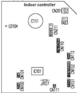
③ Remove the connector of blade motor from CN151 and CN152; Remove the wires of blade motor inside the electrical terminal block; Remove the temperature sensor connector from CN112; Remove the dynamic ground temperature sensor connector from CN110.
④ Pull out the electrical control board and disconnect the resistor JR07 on it (near CN111).
Operation
① The operation setting is still reserved at power-off.
②The air conditioner will restart automatically according to the memory after 3 minutes of power supply recovery.
Note:
•The operation setting will be reserved after 10 seconds of remote controller operation.
- When the Auto ON/OFF timer is activated, the timer setting will be cancelled in the event of power-off or power failure. As Auto Restart function is equipped inside these models, once the power is recovered, the air conditioner will start to operate three minutes later.
- If the air conditioner is turned off by the remote controller before power-off, Auto Restart function will be disabled due to power button's OFF status in the remote controller.
• In order to prevent impulse current from affecting the power supply, please arrange a sequence to start other household appliances to avoid simultaneous power-on.
2-6 Piping work
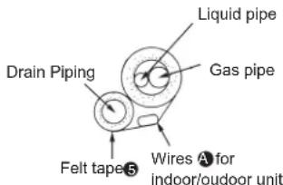
- Be sure to place drainage hose under refrigerant pipe.
- Don't make the drainage hose uplifted or bended.
- Don't bind up the hose by pulling it.
- Be sure to bind up the drainage hose with commercially available insulated material when the hose goes through room.
- Firstly wrap pipes with pipe bandage tape and package piping and drainage hose with felt tape and put them into the pipe keeping section behind this unit.
Installation instructions
Laying pipes backwards, rightwards and downwards
Piping
- Pipe layout
Put refrigerant pipe and drainage pipe together, wrap them with band.
Take care not to raise the drainage hose.
Cut this part when connecting E pipe downwards.
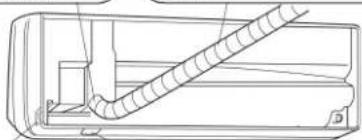
natural_image
Technical line drawing of a mechanical component with coiled spring (no text or symbols)Cut this part when connecting pipe rightwards.
Cut this part when connecting pipe downwards.
- Insert the refrigerant pipe and drainage pipe into the wall hole sleeve Ⓐ, hang the indoor unit's upper half on the mounting panel ①.
- Move the air conditioner right and left to check if it is hung on the panel ① firmly.
- Push the unit's lower half into the mounting panel ①.
Lay pipes leftwards or rear leftwards.
- Pipe layout
Put refrigerant pipe and drainage pipe together, wrap them with band first and then with felt tape 5.
Take care not to raise the drainage hose.
Cut this part when connecting pipe leftwards.
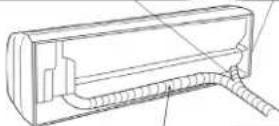
Felt tabe 5
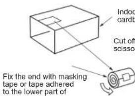
(Pipe band
Use a tape to fix the
end of the felt tape 5
Wrap the pipe from pipe end with felt tape ⑤ (The folded part of the felt tape ⑤ shall be one third of its width)
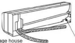
Refitting for drainage hose
The drainage hose should be refitted in the event of piping leftwards and rear leftwards. Otherwise, water dripping may result.
natural_image
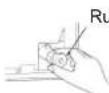
Technical line drawing of a door handle assembly (no text or symbols)1 The rubber stopper at the rear right of indoor unit.
Remove the rubber stopper by grasping the sharp lug.
Rubber stopper
2 Remove the drainage hose at the rear left side of the indoor unit.
Pull out the drainage hose by grasping the handle knob shown by arrow in the direction
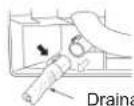
Drainage house
3 Slip the rubber stopper into the position in which the drainage pipe is installed at the rear of indoor unit.
Use an allen key to press the stopper into the joint of the drain plate.
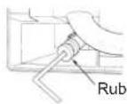
Rubber stopper
4 Connect the drainage hose to the corresponding connection position at the rear right of indoor unit.
Insert the drainage hose in the joint of the drain plate. Be sure to confirm if the hose is clamped into the prominent detent.
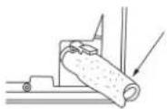
Drainage hose
Connection between the refrigerant pipe and extension pipe
If extension pipes or wires have been buried into a wall, please perform piping as described in the following key points.
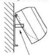
① Hook the mounting plate with indoor unit's upper part. After considering inclusion of the pipe and placing the unit as possible as close to the left, cut off a piece of packing material (used as liner) to lock the rear lug, raise the indoor unit as shown in right figure.
- Connect the refrigerant pipe and extension pipe B Cut off a part of packing material (used as liner) Lock the rear lug
Wrap the rest of cut material.
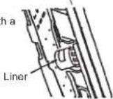
As shown above, put the liner to a notch of rear lug.
Installation of indoor unit
• Pass the pipe through the wall, hang and install the unit on the t. mounting plate ①, then push in the unit until a click is heard.
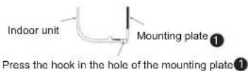
2-7 Laying drainage pipe
In order to make a smooth drainage, the drainage pipe shall be connected tilting downwards.(figure 1)
Don't connect the pipe as shown in figure2-3.
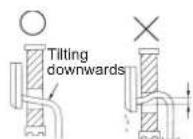
(Figure 1)
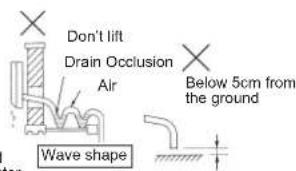
(Figure 2) (Figure 3) (Figure 4)
If it is not long enough for the drainage hose installed at the indoor unit, you can use the hose in accessory for connection. When the hose goes through room, be sure to bind up the drainage hose with commercially available insulated material.
Installation instructions
3. Installation of outdoor unit
Connection between indoor and outdoor unit
- Connect the wires from the indoor unit to the terminal bed correctly.
• Take care not to enable the wires to contact pipe.
Loose the terminal
screws
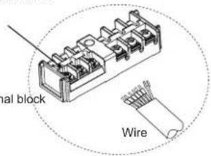
Caution
- The air conditioner can't operate normally in case of wrong connection.
• Tighten terminal screws to avoid looseness.
• After tightening of the screws, pull the wires slightly to verify whether they are tightened.
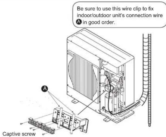
Warning
Fix the service board of outdoor unit well. Otherwise, fire and electric shock may result from entry of dust and moisture.
Caution
The mounting surface of the air conditioner should be solid enough to bear the weight. The bearing capacity shall not be lower than actually born weight (at least 200kg / m^2 ).
- The mounting surface is decorated with wooden, metallic or non-metallic structure. Corresponding measures like reinforcement, support and anti-vibration shall be taken in case of insufficient strength.
- Installation rack shall be such a fixture that the air conditioner can be fixed securely on the mounting surface.
- Confirm the diameter and depth of the mounting hole for the fixture based on hardness of the mounting surface material, select applicable expansion bolt to ensure unit's stability, firmness and reliability.
- Try to avoid rainy days, windy and snowy days as well as thundery days during installation. If necessary, relevant measures shall be taken to protect people from injury.
4. Complete indoor/outdoor unit connection and perform test run
4-1 Piping connection
① Indoor unit piping
Connect liquid and gas pipes to the unit.
*First, align with the center, tighten the pipe nut with hand until you can't proceed.
* Refer to the following torque table, use two wrenches to tighten the indoor unit side connection pipe connector. Take care not to tighten it excessively to avoid damaging the flared part.
| Pipe diameter | Torque tightened | ||
| mm | Inch | N·m | kgf·cm |
| 9.52 | 3/8 | 34.3-41.2 | 350-420 |
| 15.88 | 5/8 | 73.5-78.4 | 750-800 |
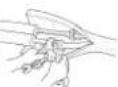

WARNING
When installing the unit, securely connect the refrigerant pipes before starting the compressor.
② Outdoor unit connection
As the same connection with that of indoor unit, connect the pipe to the outdoor unit stop valve (two or three-way) pipe connector.
Tighten the connector with the same torque as that of indoor unit by torque wrench or common wrench.
Heat insulation and wrapping band
① Pipes and valves connected at side of indoor unit should be heat insulated.
⑦ All pipes starting from the outdoor unit's pipe entrance shall be wrapped with band E.
- Fix the end of band E with tape.
- If the pipe goes through ceiling, toilet or other locations with high temperature and high humidity, please wrap the pipe with commercially available heat insulated band to avoid condensation.
4-2 Vacuumizing and leak detection test
| Vacuumizing |
| Connect the refrigerant pipe(liquidnd gas) between the indoor and out door unit |
| Remove the stop valve's service cap at the gas pipe of outdoor unit (Vacuumizing can't be done without removing the cap) |
| When vacuum pump is recommended to be used |
| Connect the manifold valve with gauge and vacuum pump to the stop valve's service port at the gas pipe of outdoor unit |
| Run the vacuum pump(vacuumize the pipe over 15 minutes) |
| Check the vacuum with the manifold valve with gauge, close the valve and stop the pump. |
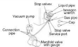
Remove the manifold valve with gauge from the stop valve service port quickly.
Open all the stop valves at liquid and gas pipes, or performance reduction or failure may result.
It's unnecessary to add refrigerant if pipe length is within the scope.
It's necessary to add proper refrigerant if pipe length exceeds the scops
Screw the service cap securely.
Screw the caps of two stop valves securely.
Make a leakage detection test.
| Tightening torque | ||
| N·m | kgf·cm | |
| Service cap | 13.7-17.7 | 140-180 |
| Shut off valve cap | 19.6-29.4 | 200-300 |
4-3 Test run
MSZ model Frequency conversion model
- Before the trial run, recheck if there is wrong connection. Wrong connection may hinder normal operation or lead to fusing as well as malfunction.
- Perform the trial run by emergency button. At the time of pressing the emergency button, the machine begins to operate in cooling mode based on optional mode for 30 minutes. The thermostat will be disabled within the 30 minutes. After the duration, the machine starts emergency operation in cooling or heating mode at the set temperature of 24^ .
- Trial run shall be performed in the following process.
Operation process
- Press the emergency button
① Press the button firstly to enable cooling operation in emergency after running for 30 minutes.
② Press the button secondly to enable heating operation in emergency.
③ Press the button thirdly to disable the operation. Each press of the emergency button enables the unit to operate following the order of ① ② ③ repeatedly.
| model | ||
| 1 | Cooling | AREA (Light) (Black out) |
| 2 | Healing | AREA (Black out) (Light) |
| 3 | Stop | AREA (Black out) (Black out) |
Caution:
- This is the indication of emergency operation mode.
Make sure to receive the signal from the remote controller
After pressing the ON/OFF button of the remote controller, please confirm whether there is beep from the indoor unit.
Under the control of remote controller, the unit will quit the emergency operation when receiving the signal from the remote controller.
- In order to protect the compressor, the outdoor unit will not be enabled even if the air conditioner restarts three minutes after stopping operation.
4-4 Notice for user information
- Based on operating instructions, please describe the way to adjust and control temperature, disassembly of air filter, way of cleaning and precautions in operation.
5. Relocation and maintenance after installation
5-1 How to install front panel
① Set the horizontal vane to position No.3 (page 10) before installing the front panel.
② Insert the bottom side of front panel under the horizontal guide vane.
③ Fix the top of the front panel securely.
④ Press the agraffe of front panel and fix the front panel on the air conditioner.
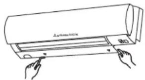
5-2 Remove the indoor unit
Pull out the bottom part of indoor unit from the mounting panel.
Loosen two angles
As shown below, pull the left and right corner part of indoor unit downwards and forwards and loosen the hook.
natural_image
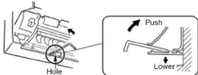
Line drawing of a hand pressing down on a cylindrical air conditioner cover (no text or symbols)If the methods above can't be adopted
If the above methods can't be adopted, remove the front panel, insert a hexagon wrench into left and right square hole, then push it upwards.
The hook will be loosened when the indoor unit bottom is pressed.
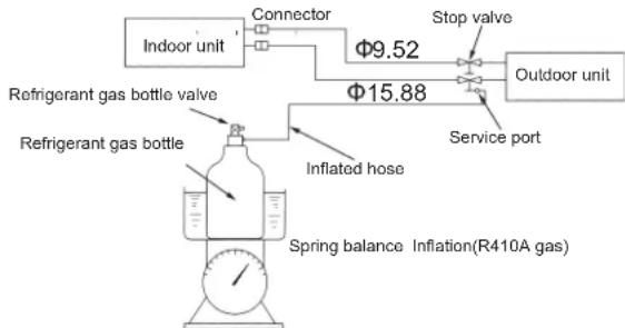
5-3 Supply of refrigerant
① Connect a gas bottle to the service port of stop valve(three way).
② Purge the pipe or hose using the refrigerant from the gas bottle.
③ Supply the refrigerant with specified amount during air conditioner operation in cooling mode.
Precautions
* During supply of the refrigerant, don't place the gas bottle upside down, or problems may result.
flowchart
graph LR
    A["Indoor unit"] --> B["Connector"]
    B --> C["Stop valve"]
    C --> D["Outdoor unit"]
    E["Refrigerant gas bottle valve"] --> F["Inflated hose"]
    G["Refrigerant gas bottle"] --> F
    F --> H["Spring balance Inflation(R410A gas)"]
    I["Φ9.52"] --> C
    J["Φ15.88"] --> C
In order to keep high pressure in gas bottle, heat the bottle with warm water (40°C) in cold weather. But don't heat it with fire or steam.
Note:
① An indoor wiring diagram is stuck inside indoor unit front panel.
② Outdoor wiring diagram is stuck on inside of service plate.
5-4 How to reclaim the refrigerant
① Be sure to use a pressure gauge.
② Enable a cooling operation first.
③ Then, close the valve (liquid valve) at high pressure side completely with the readings of 0-0.05MPa (about 30-40s) in pressure gauge, finally close the valve (gas valve) at low pressure side to stop operation immediately.
④ You can't remove the connection pipe until you ensure the closure of the two valves (liquid and gas) and power-off.
WARNING
- When reclaiming the refrigerant, stop the compressor before disconnecting the refrigerant pipes. The compressor may burst if gas (air, for example) gets into it.
- OPERATING AND INSTALLING INSTRUCTIONS
- 目 錄
- 注意
- Contents
- Thank you very much for purchasing this Mitsubishi room air conditioner.
- Safety precautions
- Symbols used in text
- Warning
- Installation of air conditioner
- Remote controller
- How to install battery and set current time
- HOW TO SWITCH OVER
- Preparation before operation
- How to use the remote controller
- Battery
- Note:
- Auto-restart function
- Auto-restart function refers
- to the following contents:...
- Indoor unit
- When the remote controller can't be used (emergency operation)
- 1
- 2
- "I FEEL..." Auto Operation
- When starting "I FEEL..." Auto Operation
- When stopping
- Auto Operation mode
- Auto Operation
- Manual operation (Cooling, Dry, Heating)
- When selecting operation mode (Cooling, dry, heating)
- When operating in Dry mode
- Notice for using air conditioner
- MOVE EYE CONTROL OPERATION...Sensible temperature
- Starting MOVE EYE control
- Cancelling MOVE EYE control
- MOVE EYE control operation
- MOVE EYE sensor
- AREA setting
- Cancelling AREA setting
- Airflow velocity and direction adjustment
- Long operation
- Mechanism of the LONG operation
- Note
- Econo cool operation
- Please operate as follows in manual cooling mode
- When quitting Econo Cool operation
- Timer operation (ON-Timer and OFF-Timer)
- How to set ON-Timer
- QUIT ON-Timer
- Combination of ON-Timer and OFF-Timer
- How to set OFF-Timer
- Quit OFF-Timer
- When the air conditioner is not used for a long time
- Not used for a long time
- To be used again
- Maintenance
- Before cleaning
- Cleaning for indoor unit
- Filter Cleaning
- Filter Cleaning (Cleaning is done once two weeks)
- Pull out the filter slightly.
- Use a cleaner to clean or use water to wash.
- After washing with water, the filter can't be used until it is dried.
- Installing the filter.
- Please check the following items before connecting a serviceman
- Please pay attention to the following condition before asking a serviceman for repair.
- When you think trouble occurs
- Removal and inspection
- Check and repair
- Operation noise should be also considered.
- When you want to remove the machine
- Waring
- Safety precautions for Installation
- For the sake of safety, please pay attention to the following safety precautions
- Users are not allowed to install the machine by themselves.
- The machine should be installed in a place which can support its weight.
- Cables between indoor and outdoor unit shall be connected properly as specified, and connecting terminals for the cables be fixed firmly without being affected by external force.
- Installation shall be implemented properly based on installation instructions
- Please ventilate room in the event of refrigerant leakage during installation.
- When installing or servicing the unit, use appropriate protective equipment and tools for safety.
- In the event of installation or removing, any substance other than refrigerant shouldn't be mixed into the refrigerant circuit.
- Don't fill other refrigerant than specified while installing or moving the unit.
- When pumping down the refrigerant, stop the compressor before disconnecting the refrigerant pipes.
- When installing the unit, securely connect the refrigerant pipes before starting the compressor.
- Electrical work should be performed according to installation instructions. Be sure to use special power supply of circuit.
- Atention for R410A refrigerant systems
- 2-1 Using R410A refrigerant air conditioners
- Caution
- 2-2 Precautions for devices that use R410A refrigerant
- Selection of installation location
- 3-1 Indoor unit
- 3-2 Outdoor unit
- ⚠ Notice
- Installation diagram and accessory
- Steps for installing drainage pipe
- Flared joint
- Installation instructions
- 1-1 How to set slide switch (inside battery box of remote controller)
- Installation for indoor unit
- 2-1 Fixing of mounting plate
- 2-2 Drilling hole in the wall
- 2-3 Specifications for power supply and connection wires
- 2-4 Connection of indoor/outdoor wires
- ⚠ Warning
- MSZ model
- Power supply check
- 2-5 Auto restart function
- How to set Auto Restart Function
- Operation
- 2-6 Piping work
- Piping
- 2-7 Laying drainage pipe
- Installation of outdoor unit
- Complete indoor/outdoor unit connection and perform test run
- 4-1 Piping connection
- 4-2 Vacuumizing and leak detection test
- 4-3 Test run
- MSZ model Frequency conversion model
- Operation process
- Caution:
- Make sure to receive the signal from the remote controller
- 4-4 Notice for user information
- Relocation and maintenance after installation
- 5-1 How to install front panel
- 5-2 Remove the indoor unit
- 5-3 Supply of refrigerant
- Precautions
- 5-4 How to reclaim the refrigerant
Brand : MITSUBISHI
Model : MSZ-WG25VA-H1
Category : Air-conditioner