Fold & Go UL 370 - Véhicule pour personnes handicapées UltraLite - Free user manual and instructions
Find the device manual for free Fold & Go UL 370 UltraLite in PDF.


User questions about Fold & Go UL 370 UltraLite
0 question about this device. Answer the ones you know or ask your own.
Ask a new question about this device
Download the instructions for your Véhicule pour personnes handicapées in PDF format for free! Find your manual Fold & Go UL 370 - UltraLite and take your electronic device back in hand. On this page are published all the documents necessary for the use of your device. Fold & Go UL 370 by UltraLite.
USER MANUAL Fold & Go UL 370 UltraLite
text_image
FOLD & GO™UL 370
Owners Manual
natural_image
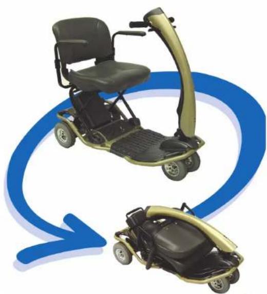
Two electric scooters with black seats and gold wheels, connected by a blue circular arrow (no text or symbols)ULTRALITE™
VEHICLES
Two Electric Avenue • P.O. Box 7025
Bellmawr, NJ 08099-9803
Toll Free I (866) 482-FOLD

Fold & Go Model 370 Owner's Manual

ULTRALITE Vehicles
Thank you for purchasing the Model 370 Fold & Go UltraLite Vehicle. With proper care, this vehicle should give you a lifetime of fun and excitement. You will enjoy the freedom to do what you want, when you want, and when you want to.
Your satisfaction means everything to us. That's why we have the best customer service in the industry. Information on our service and warranties are all spelled out in a subsequent section of this manual.
UltraLite Vehicles' mission is to provide easy to use, convenient and portable mobility products to help you get more out of your life.
Please call us at I-866-482-FOLD if you have any questions.
EMC Part: 19269600 · Rev. 03 · 4/11/05
i

ULTRALITE Vehicles


Fold & Go Model 370 Owner's Manual
Contents
Title Page
Safety Information....
Important Information Regarding Electromagnetic Interference (EMI) 3
Getting to know your Fold & Go Model 370 6
Components 6
Figure 1 — Fold & Go Model 370 Components ....6
Initial Setup 7
Installing Seat and Battery Pack 7
Seat Installation 8
Figure 2 — Installing the Seat 8
Battery Pack Installation 9
Figure 3 — Installing the Battery Pack ....9
Charging Battery 10
Figure 4 — Battery Charging, Off Vehicle ....10
Figure 5 — Battery Pack Charging Connections....11
Controls and Adjustments 12
Operating Controls....12
Dash Controls 12
Figure 6 — Dash Controls....12
Speed Control....12
Battery Gauge 13
EMC Part: 19269600 · Rev. 03 · 4/11/05
ii



Fold & Go Model 370 Owner's Manual
ULTRALITE Vehicles
Horn 13
On/Off Key 13
Figure 7 - Key Location 13
Forward/Reverse Levers 14
Adjusting Armrests 14
Figure 8 — Armrest Adjustments .... 14
Adjusting Tiller 15
Figure 9 — Tiller Adjustment .... 15
Accessories 16
Using the Fold & Go 17
Day-to-Day Use 17
Transferring On or Off the Vehicle 18
Driving 19
Speed Settings 20
Inclines....20
Cornering & Turning 21
Curbs and Small Obstacles 21
Freewheel Operation 21
Figure 10 — Brake Release Lever....21
Folding and Unfolding Operations 22
Folding Instructions 22
Unfolding Instructions 24
Disassembly & Re-Assembly 25
Figure 11 - Model 370 Dissassembled....25
Taking the Fold & Go Model 370 Apart 26
EMC Part: 19269600 · Rev. 03 · 4/11/05
iii



ULTRALITE Vehicles
Fold & Go Model 370 Owner's Manual
Figure 12 - Seat Removal....26
Figure 13 - Battery Pack Removal 26
Figure 14 - Lowering the Tiller ....27
Figure 15 - Quick Release Drivetrain handle 27
assembling the Fold & Go Model 370....28
Figure 16 - Aligning the Quick Release Drivetrain....29
Transporting the Fold & Go 30
Maintenance and Servicing 32
Preventative Maintenance 32
Seat Upholstery 32
Bodywork 33
Storage 33
Electronics 33
Motor Brakes 34
Driving Brake 34
Tires 34
Tire Pressure 34
Battery 35
Troubleshooting Guide 36
Controller Fault Codes 38
Parts Ordering/Factory Return Procedures 39
Specifications....40
Limited Warranty 41
EMC Part: 19269600 · Rev. 03 · 4/11/05
iv

Fold & Go Model 370 Owner's Manual

ULTRALITE Vehicles
Figures
Figure Number Title Page
| 1 | Fold & Go Model 370 Components | 6 |
| 2 | Installing the Seat | 8 |
| 3 | Installing the Battery Pack | 9 |
| 4 | Battery Charging, Off Vehicle | 10 |
| 5 | Battery Pack Charging Connections | 11 |
| 6 | Dash Controls | 12 |
| 7 | Key Location | 13 |
| 8 | Armrest Adjustments | 14 |
| 9 | Tiller Adjustment | 15 |
| 10 | Brake Release Lever | 21 |
| 11 | Model 370 Disassembled | 25 |
| 12 | Seat Removal | 26 |
| 13 | Battery Pack Removal | 26 |
| 14 | Lowering the Tiller | 27 |
| 15 | Quick Release Drivetrain Handle | 27 |
| 16 | Aligning the Quick Release Drivetrain | 29 |
© 2005 Electric Mobility Corp.
UltraLite™ and Fold & Go™ are trademarks of Electric Mobility Corp.
No liability is assumed with respect to the use of any information contained in this publication. While every precaution has been taken in the preparation of this publication, Electric Mobility Corp., assumes no responsibility for errors or omissions nor is any liability assumed for damages resulting from the use of information contained in this publication. This publication, as well as operational details described herein, are subject to change without notice.
EMC Part: 19269600 · Rev. 03 · 4/11/05
v

Fold & Go Model 370 Owner's Manual

ULTRALITE Vehicles
Safety Information
Read and understand these Warnings and the entire manual before using your Fold & Go Scooter. Failure to follow these instructions may result in damage to the vehicle or serious injury. NOTE: The anti-tip caster wheels may NOT prevent the scooter from tipping if scooter is used improperly.
I. DO NOT exceed the specifications of this unit, modify this unit in anyway, or use the unit for a purpose other than as intended.
2. DO NOT operate this unit if your health or medications you are taking cause you to feel dizzy, affect your vision, or in any way impact your thought process, coordination, or ability to safely operate the unit. Check with your physician should you experience any of these symptoms.
3. DO NOT operate this unit after consuming any alcoholic beverages.
4. DO NOT transfer "on" or "off" the unit until it is turned "OFF", completely stopped, and when it is on a stable and level surface.
- DO NOT attempt to ride over curbs or other obstruction higher than 2 inches.
- DO NOT stop when going up an incline. If you must do so, always lean forward to shift the center of gravity and prevent the unit from tipping.
- DO NOT climb inclines that pose a concern for stability.
- DO NOT drive across an incline or attempt to turn while on an incline.
- DO NOT back down an incline or allow the unit to be backed down an incline.
- DO NOT turn off the power while the unit is moving.
EMC Part: 19269600 · Rev. 03 · 04/11/05



ULTRALITE VEHICLES
Fold & Go Model 370 Owner's Manual
- ALWAYS remember vehicle capacity is limited to one person only. This unit is not approved for towing or for weights in excess of the published maximum.
- ALWAYS drive straight up and down inclines.
- ALWAYS turn the power off when the unit is not in use. This will not only extend the life of the charge in the battery but will keep the unit from being accidentally moved.
- ALWAYS use a grounded receptacle. Use of a non-grounded receptacle could result in an electrical shock.
- ALWAYS reduce speed when making a turn.
- ALWAYS keep arms and legs within the confines of the unit.
-
USE EXTRA CAUTION when climbing inclines (ramps, hills, driveways, etc.).
-
USE CAUTION when braking on an incline or wet or slippery surfaces as the unit will take longer to come to a complete stop.
- USE CAUTION when operating the unit in bad weather or driving through water as moisture could affect the control system or other parts of the unit either temporarily or permanently.
- OPERATOR must remain seated when the unit is moving.
- NEVER hose off your vehicle or allow it to come in direct contact with water.
- NEVER use your unit in a shower or steam room.
- NEVER charge batteries that may be frozen.
EMC Part: 19269600 · Rev. 03 · 04/11/05
2

Fold & Go Model 370 Owner's Manual

ULTRALITE
Vehicles
Important Information Regarding Electromagnetic Interference (EMI)
It is very important that you read this information regarding the possible effects of electromagnetic interference (EMI) on your scooter.
Electromagnetic interference (EMI) refers to the effects that outside sources of electromagnetic energy (radio and television broadcasts, CB radios, garage door openers, cellular telephones, etc.) might have on the control systems of your scooter. The interference from these sources could cause the scooter to release its brakes, move by itself, or to move in an unintended direction. EMI could also result in permanent damage to the control system.
The sources of electromagnetic energy can be broadly classified into three types:
- Hand held short-range portable transceivers — These are transmitter/receivers with the antenna mounted directly on the unit. Examples include: citizen band (CB) radios, "walkie-talkies", security, fire and police transceivers, cellular telephones, and devices that transmit signals even when not in use.
- Medium range mobile transceivers — These usually have the antenna mounted outside of a vehicle or building. Examples include: police, fire, ambulance and taxi transceivers.
- Long range transmitters and receivers — These usually have the antenna mounted on a tower. Examples include: commercial radio/television broadcasts and amateur (HAM) radios.

ULTRALITE
Vehicles

Fold & Go Model 370 Owner's Manual

Other types of hand-held devices like cordless phones, laptop computers, AM/FM radios, and small appliances like hair dryers or electric shavers may also generate electromagnetic energy, but it is such a small amount that, as far as we know, no EMI problems should occur with these devices.
The intensity of interference from electromagnetic energy is measured in volts per meter (v/m), which refers to the strength of the electrical source (voltage) as it relates to the distance away from the object being considered (in meters). Resistance of a scooter to a certain EMI intensity is commonly called its “immunity level.” A level of 20 volts/meter is a generally achievable and useful immunity level against interference from radio wave sources (the higher the immunity level, the greater the protection).
Your scooter has been tested and found to meet the required immunity level for Electromagnetic Interference (20 v/m).
EMC Part: 19269600 · Rev. 03 · 04/11/05
4

Fold & Go Model 370 Owner's Manual

ULTRALITE Vehicles
WARNING!
Even with an immunity level of 20 volt/meter, certain precautions must be followed to ensure that your vehicle will not be affected by outside electromagnetic sources.
- Do not operate hand-held transceivers such as citizen band (CB) radios or turn on powered communication devices such as cellular phones while the scooter is turned on.
- Be aware of nearby transmitters, such as radio and television stations, and avoid coming close to them.
- If an unintended movement should occur while operating the scooter, turn the power "off" as soon as it is safe to do so.
- Be aware that if you do operate any electrically powered accessories, radios, cellular phones, or other devices, that your scooter may become more susceptible to interference from outside electromagnetic sources.
- Report all incidents of unintended movement or unexpected brake releases to Electric Mobility's customer service department.
EMC Part: 19269600 · Rev. 03 · 04/11/05

ULTRALITE Vehicles

Fold & Go Model 370 Owner's Manual

Getting to know your Fold & Go Model 370
Your Fold & Go Model 370 scooter from UltraLite is a powerful, useful vehicle that offers increased mobility with easy, safe operation. Before using your Fold & Go, use this section to first familiarize yourself with the components, setup, controls, and adjustments to enjoy it safely and successfully.
Components
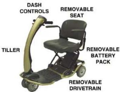
The Fold & Go Model 370 consists of the following major components. Locations are shown in Figure I.
text_image
DASH CONTROLS REMOVABLE SEAT TILLER REMOVABLE BATTERY PACK REMOVABLE DRIVETRAINFigure 1 — Fold & Go Model 370 Components
EMC Part: 19269600 · Rev. 03 · 04/11/05
6

Fold & Go Model 370 Owner's Manual

ULTRALITE Vehicles
Initial Setup
Prior to using your Fold & Go, use the following to initially setup the vehicle for proper use and safe, comfortable operation. Initial setup involves installing the seat and Battery Pack. If the vehicle is delivered with the seat and Battery Pack installed, you can skip this section and proceed with how to charge the battery before riding.
Installing Seat and Battery Pack
The Model 370 includes a removable seat and detachable Battery Pack that may require installation when you first receive it. Use the following to install the seat and Battery Pack.
EMC Part: 19269600 · Rev. 03 · 04/11/05
7

ULTRALITE VEHICLES

Fold & Go Model 370 Owner's Manual

Seat Installation
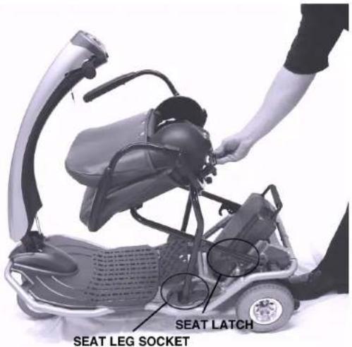
The seat is mounted on a folding, tubular frame that attaches directly to the chassis of the vehicle. A Quick-Release latch at the bottom rear of the vehicle frame secures the frame in place. To install the seat:
- Tip the seat frame forward and slide the front legs of the seat into the seat leg sockets
- Lower the rear end of the seat frame into the rear locations in the chassis
• Make sure the Seat Latch snaps into locked position
Seat installation is shown in Figure 2.
text_image
SEAT LATCH SEAT LEG SOCKETFigure 2 — Installing the Seat
EMC Part: 19269600 · Rev. 03 · 04/11/05
8

Fold & Go Model 370 Owner's Manual

ULTRALITE VEHICLES
Battery Pack Installation
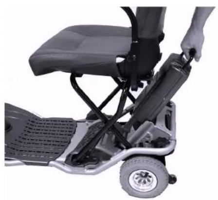
The Battery Pack is mounted directly into the frame, above the drivetrain, and secured by a spring-loaded latch. When in position, electrical contact is made automatically, no further connections are required. Battery installation is shown in Figure 3.
To install the Battery Pack:
- Use handle to lift Battery Pack into position
- Once aligned in battery slot, allow pack to slide down into place. Electrical and Mechanical connections will engage when pack is fully seated in slot.
Battery may not be fully charged upon initial installation. Refer to the following section to recharge the Battery Pack of your Fold & Go.
natural_image
Close-up of a person using a mobility scooter with a seat and wheels (no visible text or symbols)Figure 3 — Installing the Battery Pack
EMC Part: 19269600 · Rev. 03 · 04/11/05

ULTRALITE
Vehicles

Fold & Go Model 370 Owner's Manual

Charging Battery
Although the vehicle ships from the factory with the Battery fully charged, it may have become discharged during transit, storage, etc. Use the following to charge the Battery before driving.
I. Locate and identify the separate Battery Charger and AC line cord that accompanies the vehicle.
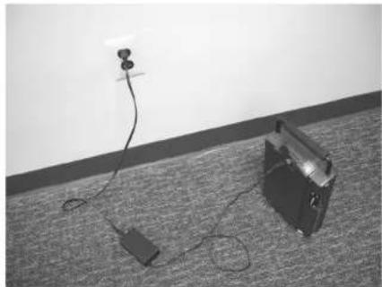
2. The Battery can be charged either on or off the vehicle. If more convenient, detach Battery from vehicle and set on dry, flat surface accessible to an electrical outlet, as shown in Figure 4.
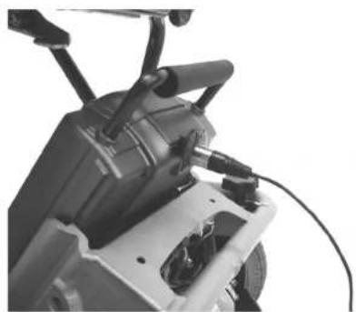
3. Locate Charger connection on upper back side of Battery housing. It is covered by a round, sliding door labeled "Charger." Battery Pack charging connection on vehicle is shown in Figure 5.
natural_image
Black-and-white photo of a small electronic device connected to a cable on a carpet, with a power outlet above (no text or symbols visible)Figure 4 — Battery Charging, Off Vehicle
EMC Part: 19269600 · Rev. 03 · 04/11/05
10

Fold & Go Model 370 Owner's Manual

ULTRALITE VEHICLES
- Attach the separate AC line cord into the Charger. Connect other end to electrical outlet. (Note: The LED will turn flashing red to show that the charger has passed the power on test and is ready for connection to the battery.)
- Plug the round, 3-prong plug attached to the Charger into connection on Battery.
- An LED Indicator on the charger housing should appear red while charging. When LED appears green, Battery is fully charged.
- If Battery was removed from vehicle, replace it into frame and make sure latch secures it in place.
natural_image
Close-up of a mechanical device with visible wiring and components (no text or symbols)Figure 5 — Battery Pack Charging Connection
EMC Part: 19269600 · Rev. 03 · 04/11/05

ULTRALITE
Vehicles

Fold & Go Model 370 Owner's Manual

Controls and Adjustments
Before driving, it is suggested that you learn about the controls of the scooter and how to perform some initial adjustments to increase safety and improve rider comfort.
Operating Controls
The vehicle includes the following controls used for operation.
Dash Controls
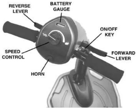
All major controls used while driving are located on the dash mounted on the front tiller. The dash of the Model 370 is shown in Figure 6. Each control is described in the following.
Speed Control — The Speed Dial regulates the maximum speed. Start at the slowest speed until you feel confident with controlling your vehicle safely. Turning the speed dial to the left (towards the turtle symbol) decreases maximum speed. Turning it to the right (towards the rabbit symbol) increases maximum speed.
text_image
REVERSE LEVER BATTERY GUAGE ON/OFF KEY SPEED CONTROL HORN FORWARD LEVERFigure 6 — Dash Controls
EMC Part: 19269600 · Rev. 03 · 04/11/05
12

Fold & Go Model 370 Owner's Manual

ULTRALITE VEHICLES
Battery Gauge — The 370 includes an illuminated Battery Gauge that provides a visual indication of the electrical charge in the Battery Pack. It consists of 10 different LED bars (3 red, 4 amber and 3 green), that are lit in accordance with the state of battery charge.
- If all bars are lit — indicates Battery Pack is fully charged
- If only red and amber bars are lit — indicates Battery Pack charge is low
- If only red bars are lit or flashing — indicates Battery Pack requires immediate recharging
Horn — Pressing the horn button on the dash sounds the horn. Releasing the horn button deactivates the horn. The horn is useful to warn people or animals that you are coming towards them. You may also find it helpful to use it when rounding blind corners or going in reverse.
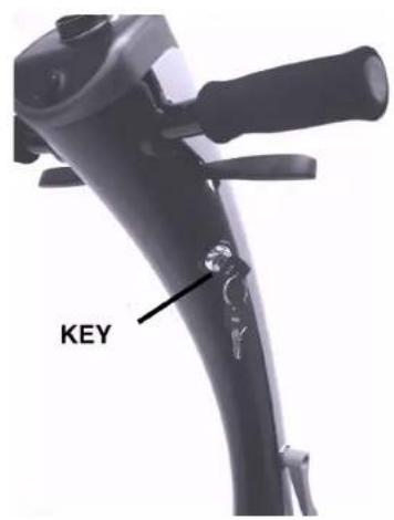
On/Off Key — Controls power. Turning the key clockwise turns power "On." When "On" the Battery Gauge will indicate battery level. Turning the key counterclockwise turns the vehicle "Off." Key should always be in the "Off" position when transferring on or off scooter.
text_image
KEYFigure 7 — Key Location
EMC Part: 19269600 · Rev. 03 · 04/11/05

ULTRALITE
Vehicles

Fold & Go Model 370 Owner's Manual

Forward/Reverse Levers — Selects movement direction and speed of the vehicle. To move forward, squeeze the right lever towards the handle grip. To move in reverse, squeeze the left lever towards the handle grip. Operating speed is proportional to the amount you squeeze each lever. Smoother starts and stops can be accomplished by gradually moving each lever.
Adjusting Armrests
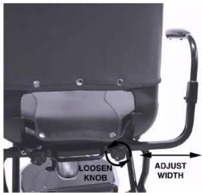
Your vehicle includes armrests. You can adjust the width between armrest so that you are seated in the most comfortable position possible. Armrest adjustments are shown in Figure 8.
To adjust armrest width:
- Loosen Adjustment Knobs on armrest bracket
- Slide armrest support to desired position
- Tighten Adjustment Knob to secure armrest bracket
- Repeat with other side armrest
Additionally, the armrests can be folded down and out of the way for easier movement in and out of the seat. Lift the armrest up at the rear to disengage and fold downward. Moving armrest up and lifting at rear until it engages into bracket returns armrest to riding position.
text_image
LOOSEN KNOB ADJUST WIDTHFigure 8 — Armrest Adjustments
EMC Part: 19269600 · Rev. 03 · 04/11/05
14

Fold & Go Model 370 Owner's Manual

ULTRALITE VEHICLES
WARNING!
DO NOT use armrest as support when transferring on or off the vehicle. Armrests are not designed to support weight of rider when getting on or off the seat.
Adjusting Tiller
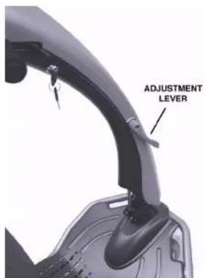
The angle of the tiller and dash may be adjusted to the individual rider's preference. Multiple angles are available to reposition the tiller. The side tiller mounted Adjustment Lever is used to reposition tiller.
To change tiller position:
• Pull lever towards you to release tiller
- M ove tiller to desired angle
- Release lever to secure tiller at desired position.
Tiller Adjustment Lever is shown in Figure 9.
text_image
ADJUSTMENT LEVERFigure 9 — Tiller Adjustment
EMC Part: 19269600 · Rev. 03 · 04/11/05



Fold & Go Model 370 Owner's Manual

Accessories
Your Fold & Go Model 370 can include several useful accessories to make your riding experience more enjoyable, convenient, and easier. These accessories can include:
- Lifting Harness
- Storage Bags
• B average Holder - Extra Battery Pack
- Headlight
- Brake light
- Sideview Mirror
These accessories are available separately and come with complete instructions for installation and use with your Fold & Go vehicle. Contact your UltraLite Customer Service representative for further information.
EMC Part: 19269600 · Rev. 03 · 04/11/05
16

Fold & Go Model 370 Owner's Manual

ULTRALITE Vehicles
Using the Fold & Go
Once you've gotten familiar with the Fold & Go Model 370 components, controls, and have charged the Battery Pack, you can use the following section to use it. This section presents instructions for:
• D a y-to-Day Use
- Folding & Unfolding
• Shipping and Transport
If you are unsure of how to operate your vehicle, go back to the previous section before attempting any use.
Day-to-Day Use
The following describes using your Fold & Go during general, daily operation, including:
• T ransferring On & Off
- Driving
- F reewheel Operation
Additional information, including folding/unfolding and disassembling the Fold & Go for transport and storage is presented in a subsequent section (see page 22).
EMC Part: 19269600 · Rev. 03 · 04/11/05



Fold & Go Model 370 Owner's Manual

Transferring On or Off the Vehicle
Your Fold & Go has been designed to make transferring on and off the vehicle as easy as possible.
WARNING!
Make sure key is either in the OFF position or removed before transferring ON or OFF the vehicle.
Use the following recommendations to assist you in making a more comfortable transfer.
- Use the Tiller Pivot Release to move Tiller away from seat for ease of transfer.
- Lift the folding armrests of the seat up and out of your way. Be sure to move them down into the riding position before operating.
- Use the footrest area of the frame for assistance when transferring on and off.
EMC Part: 19269600 · Rev. 03 · 04/11/05
18

Fold & Go Model 370 Owner's Manual

ULTRALITE Vehicles
Driving
Once seated on your vehicle, driving is as simple as using the Engager Levers to move forward (right lever) or reverse (left lever) and steering in the desired direction. Before driving, however, you should keep in mind the following recommendations.
- Tiller is adjusted to comfortable riding position.
- Seat is locked onto frame. Check latching lever.
- Motor is engaged. Check Brake Lever. Should be in "DRIVE" position.
• Armrests are locked into driving position.
WARNING!
If any of these items are questionable, DO NOT OPERATE! Check before driving. Failure to disregard these conditions may cause accidents or injuries.
EMC Part: 19269600 · Rev. 03 · 04/11/05

ULTRALITE Vehicles

Fold & Go Model 370 Owner's Manual

Speed Settings
The overall forward/reverse speed range of the vehicle is selected from the Speed Control knob on the dash. Lower settings (indicated by the turtle symbol) result in slower speeds. Higher settings (indicated by the rabbit symbol) provide faster speeds.
When first operating your vehicle, select slower settings until you feel comfortable.
Inclines
It is recommended that speed be reduced when traveling on (up or down) inclines. Select the slowest speed setting that will still allow the vehicle to climb the incline.
NEVER try to turn around on an incline!
If vehicle stops on an incline, DO NOT attempt to continue.
When stopped on an incline, back down with the speed set at "slow" and back down in one continuous movement. DO NOT start and stop.
Always lean forward when traveling on inclines (up or down) for greater stability.
EMC Part: 19269600 · Rev. 03 · 04/11/05
20

Fold & Go Model 370 Owner's Manual

ULTRALITE
Vehicles
Cornering & Turning
ALWAYS reduce to a safe speed when making a turn or going around a corner.
Curbs and Small Obstacles
DO NOT attempt to ride over curbs or any other obstructions higher than 2 inches (5 cm).
Freewheel Operation
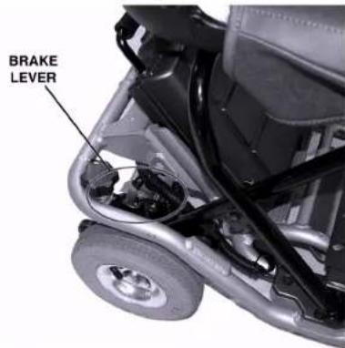
The Fold & Go features a "freewheel" mode to allow it to be pushed by hand. To activate manually, turn the key switch OFF and locate the brake release lever on the right side of the drivetrain. The Brake Release Lever is shown in Figure 10.
Push lever towards front of vehicle, "NEUTRAL" position, to disengage the brake. Move lever back towards rear of vehicle, "DRIVE" position, to reengage the brake. When your vehicle is in "freewheel" mode, brakes will not operate.
WARNING! Never sit in vehicle if it is in "freewheel" mode on an incline.
text_image
BRAKE LEVERFigure 10 — Brake Release Lever
EMC Part: 19269600 · Rev. 03 · 04/11/05



Fold & Go Model 370 Owner's Manual

Folding and Unfolding Operations
The ability to easily and safely fold and stow the vehicle and later unfold and use it is a prime feature of the Fold & Go vehicle. Instructions to fold and unfold are presented in the following. No tools are required to either fold or unfold the vehicle and it can safely be performed by one person.
Folding Instructions
- Turn key switch to "Off" position.
- Remove battery pack by simply pulling upright on the battery pack handle, the lock latch will automatically disengage. Using the handle, carefully lift the battery pack up and away from frame.
- Grasp the seat handle at the rear of the seat bottom and depress the seat latch to unlock the seat frame.
- Pulling seat rearward, swing the inner seat legs away from the latch, while lifting the seat by the seat handle. This will move the lower portion of the inner seat legs to the rear and out of the front seat leg sockets.
- Swing the inner seat leg forward and gently lower the seat to the frame, fold down the seat back and arms. The seat will nest neatly on the frame.
- Remove front basket (if required) by pulling upright on the basket.
EMC Part: 19269600 · Rev. 03 · 04/11/05
22

Fold & Go Model 370 Owner's Manual

ULTRALITE Vehicles
- Using the Tiller Adjustment Lever, release the tiller and fold the tiller down. Secure tiller with provided velcro straps.
With the vehicle in this folded position, you can easily lift the front end by the frame handle and roll it on the anti-tip casters.
Warning!
Do not place metal objects over open battery terminals. May cause short circuits.
You can remove the seat either folded or unfolded. To remove the seat in its folded, flat position, release the seat latch handle at the left rear of the frame and lift the seat away. Be sure to hold the seat frame while you lift the seat.
To remove the seat in its unfolded, upright position, release the seat latch handle and pivot the rear of the seat upward, then slide the front legs rearward out of the leg sockets. The latched unfolded seat may be used as a portable, lightweight seat when it is not attached. If you sit in the seat when it is detached, be sure to place it on a firm, level surface.
EMC Part: 19269600 · Rev. 03 · 04/11/05



Fold & Go Model 370 Owner's Manual

Unfolding Instructions
- Using the Tiller Adjustment Lever, lift the tiller into riding position.
- Unfold and install the seat being certain to insert the front frame legs into the frame sockets. Check the seat latches to be sure they are secure.
- Lift the seat back and unfold the seat arms (if applicable).
- Install the Battery. Verify that the pack is fully seated into position.
- Turn on power at key.
EMC Part: 19269600 · Rev. 03 · 04/11/05
24

Fold & Go Model 370 Owner's Manual

ULTRALITE
Vehicles
Disassembly & Re-Assembly
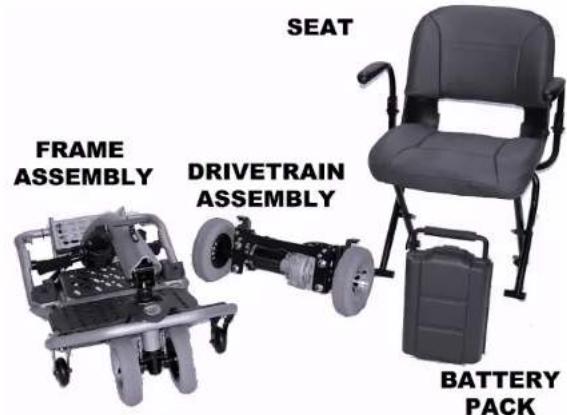
In addition to easily folding and unfolding, the Fold & Go Model 370 can be quickly and easily disassembled into four components for storage or transport, then re-assembled when needed. Instructions to take your Fold & Go Model 370 apart and put it back together are presented in this section.
text_image
SEAT FRAME ASSEMBLY DRIVETRAIN ASSEMBLY BATTERY PACKFigure 11 — Model 370 Disassembled
EMC Part: 19269600 · Rev. 03 · 04/11/05




Fold & Go Model 370 Owner's Manual
Taking the Fold & Go Model 370 Apart
Taking the Model 370 apart involves removing the seat and Battery Pack, lowering the tiller assembly, and removing the drivetrain. Instructions to disassemble the Model 370 appear in the following.
- Turn power "OFF." Fold seat back down.
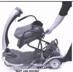
- Pull seat latch bar on rear underside of seat frame. Lift rear of seat and slide seat to disengage from the frame (see Figure 12).
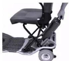
- Lift Battery Pack by handle and pull up to remove Battery Pack, as shown in Figure 13.
text_image
SEAT LATCH SEAT LEG SOCKETFigure 12 — Seat Removal
natural_image
Close-up of a person's wheelchair seat and steering wheel (no visible text or symbols)Figure 13 — Battery Pack Removal
EMC Part: 19269600 · Rev. 03 · 04/11/05

Fold & Go Model 370 Owner's Manual

ULTRALITE VEHICLES
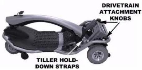
- Rotate Tiller Release Lever and lower tiller onto frame. Secure Tiller to Frame with provided straps.
- Unplug drivetrain motor from connection beneath frame by squeezing plug sides inward and pulling to disconnect. Loosen and remove the two Drivetrain Attachment Knobs on the back of the folding chassis, as shown in Figure 14. Lift rear of scoter. Drivetrain will release and remain on the ground.
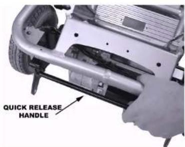
- (For models equipped with Quick Release Drivetrain) Pull quick release drivetrain handle, as shown in Figure 15. While handle is pulled, lift rear of scooter. Drivetrain will automatically release electrically and remain on the ground.
If you are disassembling the Fold & Go Model 370 for shipping or transport, refer to "Transporting the Fold & Go Model 370" on page 36 for recommendations and procedures suggested for easy transport.
text_image
DRIVETRAIN ATTACHMENT KNOBS TILLER HOLD- DOWN STRAPSFigure 14 — Lowering the Tiller
text_image
QUICK RELEASE HANDLEFigure 15 — Quick Release Drivetrain Handle



Fold & Go Model 370 Owner's Manual

Re-assembling the Fold & Go Model 370
Putting the Model 370 back together involves re-attaching the drivetrain, installing the seat, raising & locking the seat frame, and re-positioning the tiller and dash for driving operation. Instructions to re-assemble the Model 370 are provided in this section.
- Place drivetrain on firm, level surface with drivetrain rear anti-tip casters facing the rear of the scooter.
- Position rear of frame over top of drivetrain so that slots in the rear of the frame align with struts of the drivetrain. Slide frame onto drivetrain. Install drivetrain knobs and tighten fully. Plug drivetrain into connection on frame.
EMC Part: 19269600 · Rev. 03 · 04/11/05
28

Fold & Go Model 370 Owner's Manual

ULTRALITE VEHICLES
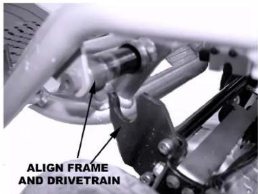
- (For models equipped with Quick Release Drivetrain) Position rear of frame over top of drivetrain so that slots of the drivetrain align with struts in the rear of the frame, as shown in Figure 16. Slide frame onto drivetrain. Push down on rear of frame until Drivetrain clicks into position.
- Make sure brake lever is in drive mode (Fuel Gauge will flash on & off if Brake is in push mode and key is "On").
- Position seat frame into position, making sure seat legs are repositioned into front leg sockets on frame. crossover bar seats onto folding chassis. (Reference Figure 2 - pg 8) Lower seat frame until rear seat latch snaps into locked position onto frame.
- Install Battery Pack (see "Installing the Battery Pack" on page 9).
- Position tiller into preferred driving positions.
- Turn key to "ON" position. If no power or fuel gauge is flashing, check connection at drivetrain or confirm that brake lever is in drive mode.
text_image
ALIGN FRAME AND DRIVETRAINFigure 16 — Aligning the Quick Release Drivetrain
EMC Part: 19269600 · Rev. 03 · 04/11/05

ULTRALITE Vehicles

Fold & Go Model 370 Owner's Manual

Transporting the Fold & Go
By Car — To transport your Fold & Go by car, place each of the components into the trunk, being careful not to scratch or mark any of the finished surfaces. If you need assistance lifting weights, consider asking UltraLite's Customer Service Department or your authorized service center about the Power Trunk Lift. This device will assist you in transporting your Fold & Go by transferring the scooter or its components in and out of your trunk with very little effort. (See "Specifications" for more information on weights).
By Airplane — To transport your Fold & Go on an airplane, we recommend that you call your airline at least 24 hours in advance to ensure that they are able to handle your vehicle properly. Ask your airline whether they will need to disassemble the Fold & Go or whether they plan to load and store it on the plane without disassembly. Ask specifically where and with whom you should drop the unit off and where and with whom you should retrieve it at your destination.
Note: Only sealed lead-acid or sealed gel batteries are Federal Aviation Authority (FAA) approved for air travel. Your scooter, Model 370, is equipped with Airline Approved sealed lead acid batteries.
Remember to bring this manual with you as a reference on your trip. Your manual will assist you in disassembling and reassembling your Fold & Go if required.
Prior to leaving the airport, remember to test the Fold & Go when first getting on it. Direct any questions to the airline personnel if the unit does not work as it did prior to transportation.
EMC Part: 19269600 · Rev. 03 · 04/11/05
30

Fold & Go Model 370 Owner's Manual

ULTRALITE
Vehicles
If traveling outside of the United States, you may require a different charger or an adapter for your present charger. Customer Service or your authorized service center can help you answer these questions and supply you with the charger or adapter you require.
By Bus, Van or Truck without Disassembly — If transporting your Fold & Go fully assembled in a van, bus, or truck, secure it to the floor using a four point tie-down system.
The operator should then be seated in an approved seat somewhere in the transporting vehicle.
WARNING!
This vehicle does not meet Federal Safety Standards for motor vehicle seating. Do not sit, nor permit anyone else to sit, in the seat of the scooter during transportation in a motor vehicle as this poses a significant risk of bodily injury or even death.
EMC Part: 19269600 · Rev. 03 · 04/11/05



Fold & Go Model 370 Owner's Manual

Maintenance and Servicing
This section presents information to keep your Fold & Go in peak operating condition, including:
• P preventative Maintenance
• Troubleshooting
• Factory Return Procedures
Your Fold & Go requires only minimal maintenance and by setting time aside each month for careful inspection and checking items included in this section, you can be assured of a long, useful life of your Fold & Go vehicle.
Preventative Maintenance
Performing periodic preventative maintenance on your Fold & Go will ensure long, useful operational life as well as identifying any potential problems that may occur that might effect safe use and operation of the vehicle. Maintenance topics are presented in the following. For convenience, a Preventative Maintenance Checklist is also included as an aid in performing and recording maintenance of your Fold & Go.
Seat Upholstery
A damp cloth and a mild soap will keep your seat and backrest looking good. Do not use abrasive cleaners as this will damage the coating. Upholstery can also be damaged by chemical cleaners
EMC Part: 19269600 · Rev. 03 · 04/11/05
32

Fold & Go Model 370 Owner's Manual

ULTRALITE Vehicles
Ultra-violet light can also reduce the life of the upholstery coating material. This is a normal aging process and cannot be guaranteed.
Bodywork The bodywork on your Fold & Go Vehicle can be lightly washed with a damp cloth and mild soap and water. Auto polish can be used to keep the paint in good condition. Do not use abrasive cleaners or strong detergents, because this will fade the color.
CAUTION!
Do not hose down your Fold & Go Vehicle. Water could penetrate the electronics and cause permanent damage.
| Storage | DO NOT store your Fold & Go Vehicle in damp conditions. This may affect the electronics if left for very long periods of time. |
| Electronics | Servicing of the drive electronics and charger should only be carried out by your local UltraLite Vehicles service center. These units are sealed and should not be opened.BROKEN SEALS WILL VOID YOUR WARRANTY.DO NOT operate your Fold & Go Vehicle in extreme weather conditions, i.e. very heavy rain or snow.DO NOT drive through water. This may damage the main electronic controller of your Fold & Go Vehicle.Safety Note:For your own safety, we recommend that you check the function of your Fold & Go Vehicle brakes prior to use. |
EMC Part: 19269600 · Rev. 03 · 04/11/05




Fold & Go Model 370 Owner's Manual
Motor Brakes
If the motor brakes are functioning correctly, you will not be able to push your machine when the key is switched off or switched on with the brake lever in the "DRIVE" position.
Driving Brake
When you drive your Fold & Go Vehicle and let go of the control lever, your vehicle should reduce speed very quickly and come to a gentle stop. If you notice a change in the normal driving/slowing condition and your Fold & Go Vehicle does not slow down quickly, please do not use your vehicle and contact your local UltraLite Vehicles service center or call 1-800-743-1302
Tires
Check the condition of your tires regularly. Look for signs of wear, cuts and foreign objects lodged in the tread. Your vehicle is equipped with puncture resistant, 6-ply tires, eliminating the worry of being stranded with a flat tire. Should your tire lose pressure, you will be able to continue your journey but have the tire checked at your destination.
Tire Pressure
Your scooter is equipped with pneumatic tires, fill to 33-36 psi (front) and 47-50 psi (rear). Check air pressure monthly.
Your Fold & Go Vehicle has air filled tires, you should check the tire pressure regularly. Tire pressure should be properly maintained. DO NOT over inflate the tires. It is not recommended to operate the vehicle with under inflated or over inflated tires.
EMC Part: 19269600 · Rev. 03 · 04/11/05
34

Fold & Go Model 370 Owner's Manual

ULTRALITE
Vehicles
Battery
Keep your battery well charged (see Battery Charging section). Keep battery clean and in a dry frost-proof place. Keep battery contacts clean. To clean brush lightly with fine sand paper.
IMPORTANT!
It is not possible to predict the life expectancy of your battery. Different workloads will affect battery accordingly.
Some Fold & Go Vehicle users will use their vehicle every day and for long periods of time. Their battery will receive a near total discharge, and the life of their battery will be short (12 months or less in some cases). Other Fold & Go Vehicle users will use their vehicles less frequently, putting their battery through a less demanding discharge life-style. These batteries will probably have a longer life (12 to 24 months or longer).
EMC Part: 19269600 · Rev. 03 · 04/11/05



Fold & Go Model 370 Owner's Manual

Troubleshooting Guide
This table is only a guide to aid you in getting your vehicle operating, should you have any problems. If you are unable to get your vehicle operating, call either Electric Mobility Customer Service toll free number located at the front of this manual or your local Authorized Service Center.
Symptom Possible Cause Solution
Unit does not move I. Keyswitch not "ON" I. Turn keyswitch to "ON"
- Manual release in 'Push Mode' 2. Lift brake lever to 'Ride Mode'
- Battery power low 3. Recharge batteries
- Power harness loose or unplugged 4. Plug harness into connector
- Vehicle shuts down to conserve battery 5. Cycle keyswitch
Vehicle feels wobbly when driven
- Tire damaged
- Seat is loose
I. Replace tire
- Check seat for loose hardware or damage and assure latch is closed around seat frame.
EMC Part: 19269600 · Rev. 03 · 04/11/05
36

Fold & Go Model 370 Owner's Manual

ULTRALITE Vehicles
Range less than expected
| 1. Charging too infrequently | 1. Charge unit more often |
| 2. Defective or worn out battery | 2. Load test batteries. If necessary replace |
| 3. Cold weather reduces battery life | 3. Allow batteries to reach room temperature and then fully recharge |
| 4. Defective charger | 4. Contact Electric Mobility or your Authorized Service Center |
Erratic behavior when
| engager operated I. Faulty engager 1. Contact Electric Mobility or your | ||
| 2. Defective wiring harness 2. Replace harness | Authorized Service Center | |
| Battery Pack LED not lit | 1. Cord not properly plugged-in | 1. Verify cord correctly plugged-in at both Battery Pack and electrical outlet |
| 2. Faulty charger | 2. Contact Electric Mobility or your Authorized Service Center | |
| Brake squeals | 1. Setscrew loose | 1. Tighten setscrew - Brake nut should be set 1/6" from brake pad |
| 2. Dirt in brake pad | 2. Blow dirt out with air pressure hose | |
EMC Part: 19269600 · Rev. 03 · 04/11/05




Fold & Go Model 370 Owner's Manual
Brake release lever
sticks I. Rust and corrosion I. Spray ball detent area with lubrication
oil. Be careful not to get oil onto the brake pad
Stiffness in steering
- Possible grime build up
I. Lubricate bearings
- Bearings in head tube worn 2. Replace bearings
Controller Fault Codes
In addition to the troubleshooting information in the previous section, the controller used in the Model 370 Fold & Go provides diagnostic information through means of a Fault Code Display that appears on the Battery Gauge. When a fault is detected, selected segments of the Battery Gauge will light to indicate the faults. Codes and faults are listed in the following.
Battery Gauge LED Segment Lit Meaning and What To Do
| 1 | Battery needs recharging or bad connection with battery. Check connections, recharge battery. |
| 2 | Bad motor connection. Check all connections between controller and motor. |
| 3 | Short circuit between motor and battery connection. Contact authorized service facility. |
| 4 & 5 | (not used) |
EMC Part: 19269600 · Rev. 03 · 04/11/05
38

Fold & Go Model 370 Owner's Manual

ULTRALITE Vehicles
6 Controller inhibited from operation. Disconnect battery charger.
7 Throttle fault. Engager levers must be in neutral (centered) position before vehicle is turned on. Switch vehicle off, center levers, and switch back
8 Controller fault. Check all connections.
9 Bad parking brake connection. Check parking brake and motor connections.
10 Excessive voltage detected at controller. Check battery connections.\
Flashing LEDs Controller has entered Sleep mode. Cycle Key Off/On to reset.
Parts Ordering Procedures
To help us serve you as quickly as possible have your phone number, vehicle serial number or your order number ready when you call.
When ordering parts, please have your method of payment ready (i.e., credit card number and expiration date, check, etc.). All parts are shipped UPS Ground. Alternate shipping arrangements may be made for an additional charge based on weight and destination (i.e. UPS Next Day, UPS 2nd Day, etc.).
Factory Return Procedures
If a part or the entire product is to be returned, call Electric Mobility Customer Service Center to obtain a Return Authorization Number that must be placed on the return package. This number is used to identify the customer, the part and the type of repair. Any part or product received without this number will be returned to the sender at the sender's expense. In the event that you must return the product, a Customer Service Representative can help you make the necessary arrangements.
EMC Part: 19269600 · Rev. 03 · 04/11/05




Fold & Go Model 370 Owner's Manual
Specifications
Model Designation Model 370
Length 40"
Wheelbase 19.75"
Height 36"
Folded Height with seat 18"
Weight Capacity 250 lb.
Weight, without batteries 69.5 lb.
Weight, with batteries 86.5 lb.
Weight, heaviest part 27.4 lb.
Battery Weight 17 lb.
Drive Mechanism Rear wheels driven directly by differential gear
Seat Height 23"
Deck To Seat Height 18"
Motor Size 200W
Ground Clearance ^3 3.5"
Maximum Speed ^2 3.8 mph
Travel Range ^2 10 miles
Safe Climbing Angle 10° (225lbs.) / 8° (250lbs.)
Charger 110/220V 1200 mA
' Seat height measured from floor to top of seat cushion
^2 Unit speed and travel range varies by terrain and weight of rider
^3 Measured at center of frame. Does not include anti-tip wheels.
EMC Part: 19269600 · Rev. 03 · 04/11/05
40

Fold & Go Model 370 Owner's Manual

ULTRALITE Vehicles
Limited Warranty
UltraLite Vehicles warrants the vehicle other than its component battery or batteries, to be free from defects in materials and workmanship for a period of one (1) year from the date of purchase. If, within such warranty period, any such product shall be proven to UltraLite Vehicles satisfaction to be defective, such product shall, at option, be repaired or replaced. Sole obligation and your exclusive remedy under this warranty shall be limited to such repair and/or replacement.
For warranty service please contact UltraLite Vehicles at: 1-800-743-1302.
Limitations and Exclusions
The foregoing warranty shall not apply to products subjected to negligence, accidents, improper operation, maintenance or storage, commercial, institutional, or service use other than normal application, or to products damaged by reason of repairs or modifications made to any product without the specific written consent of UltraLite Vehicles, or products damaged by circumstances beyond UltraLite Vehicles control.
The foregoing warranty is exclusive and in lieu of all other express warranties, implied warranties, if any, including but not limited to the implied warranties of merchant ability and fitness for a particular purpose, and shall not extend beyond the duration of the express warranty provided herein. UltraLite Vehicles shall not be liable for any consequential or incidental damages whatsoever.
EMC Part: 19269600 · Rev. 03 · 04/11/05

text_image
ULTRALITE Vehicles Fold & Go Model 370 Owner's ManualEMC Part: 19269600 · Rev. 03 · 04/11/05
42