
EX5R - Synthesizer YAMAHA - Free user manual and instructions
Find the device manual for free EX5R YAMAHA in PDF.

| Product Type | Rackmount Synthesizer |
| Model | Yamaha EX5R |
| Synthesis Types | AWM2, AN (Analog Physical Modeling), FDSP, VL (for EX5/EX5R) |
| Polyphony | 64 notes |
| Multitimbral Parts | 16 |
| Sequencer | 16 tracks, song and pattern modes, real-time and step recording |
| Arpeggiator | Yes, multiple arpeggio types with editable patterns |
| Effects | Reverb, Chorus, 2 Insertion effects per voice, system effects |
| Sampling | Yes, 16-bit, record and playback, sample editing |
| Storage | Internal memory, floppy disk drive, SCSI for external storage |
| Display | LCD with backlight |
| Connectivity | MIDI In/Out/Thru, analog outputs (L/R), headphone, SCSI, footswitch, breath controller |
| Power Supply | AC 120V/230V switchable, IEC connector |
| Dimensions (W x H x D) | 482 x 133 x 380 mm (19-inch rack, 3U) |
| Weight | 8.5 kg |
| Safety | Grounded plug, do not open, refer servicing to qualified personnel |
| Maintenance | Clean with soft dry cloth; avoid liquids and solvents |
| Reparability | No user-serviceable parts inside; consult qualified service |
| Accessories | Power cord, user manual, floppy disk (if included) |
| Warranty | Standard Yamaha warranty; modifications void warranty |
Frequently Asked Questions - EX5R YAMAHA
User questions about EX5R YAMAHA
0 question about this device. Answer the ones you know or ask your own.
Ask a new question about this device
Download the instructions for your Synthesizer in PDF format for free! Find your manual EX5R - YAMAHA and take your electronic device back in hand. On this page are published all the documents necessary for the use of your device. EX5R by YAMAHA.
USER MANUAL EX5R YAMAHA
PRODUCT SAFETY MARKINGS: Yamaha electronic products may have either labels similar to the graphics shown below or molded/stamped facsimiles of these graphics on the enclosure. The explanation of these graphics appears on this page. Please observe all cautions indicated on this page and those indicated in the safety instruction section.
CAUTION
RISK OF ELECTRIC SHOCK DO NOT OPEN

CAUTION: TO REDUCE THE RISK OF ELECTRIC SHOCK.
DO NOT REMOVE COVER (OR BACK).
NO USER-SERVICEABLE PARTS INSIDE.
REFER SERVICING TO QUALIFIED SERVICE PERSONNEL.

The exclamation point within the equilateral triangle is intended to alert the user to the presence of important operating and maintenance (servicing) instructions in the literature accompanying the product.
The lightning flash with arrowhead symbol, within the equilateral triangle, is intended to alert the user to the presence of uninsulated “dangerous voltage” within the product’s enclosure that may be of sufficient magnitude to constitute a risk of electrical shock.
IMPORTANT NOTICE: All Yamaha electronic products are tested and approved by an independent safety testing laboratory in order that you may be sure that when it is properly installed and used in its normal and customary manner, all foreseeable risks have been eliminated. DO NOT modify this unit or commission others to do so unless specifically authorized by Yamaha. Product performance and/or safety standards may be diminished. Claims filed under the expressed warranty may be denied if the unit is/has been modified. Implied warranties may also be affected.
SPECIFICATIONS SUBJECT TO CHANGE: The information contained in this manual is believed to be correct at the time of printing. However, Yamaha reserves the right to change or modify any of the specifications without notice or obligation to update existing units.
ENVIRONMENTAL ISSUES: Yamaha strives to produce products that are both user safe and environmentally friendly. We sincerely believe that our products and the production methods used to produce them, meet these goals. In keeping with both the letter and the spirit of the law, we want you to be aware of the following:
Battery Notice: This product MAY contain a small non-rechargeable battery which (if applicable) is soldered in place. The average life span of this type of battery is approximately five years. When replacement becomes necessary, contact a qualified service representative to perform the replacement.
Warning: Do not attempt to recharge, disassemble, or incinerate this type of battery. Keep all batteries away from children. Dispose of used batteries promptly and as regulated by applicable laws. Note: In some areas, the servicer is required by law to return the defective parts. However, you do have the option of having the servicer dispose of these parts for you.
Disposal Notice: Should this product become damaged beyond repair, or for some reason its useful life is considered to be at an end, please observe all local, state, and federal regulations that relate to the disposal of products that contain lead, batteries, plastics, etc.
NOTICE: Service charges incurred due to lack of knowledge relating to how a function or effect works (when the unit is operating as designed) are not covered by the manufacturer's warranty, and are therefore the owners responsibility. Please study this manual carefully and consult your dealer before requesting service.
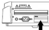
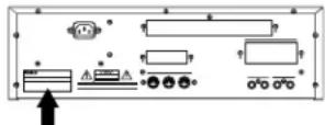
NAME PLATE LOCATION: The graphic below indicates the location of the name plate. The model number, serial number, power requirements, etc., are located on this plate. You should record the model number, serial number, and the date of purchase in the spaces provided below and retain this manual as a permanent record of your purchase.
EX5/EX7
YAMAHA
EX5R
Model
Serial No. ____
Purchase Date ____
IMPORTANT SAFETY INSTRUCTIONS
INFORMATION RELATING TO PERSONAL INJURY, ELECTRICAL SHOCK, AND FIRE HAZARD POSSIBILITIES HAS BEEN INCLUDED IN THIS LIST.
WARNING- When using any electrical or electronic product, basic precautions should always be followed. These precautions include, but are not limited to, the following:
- Read all Safety Instructions, Installation Instructions, Special Message Section items, and any Assembly Instructions found in this manual BEFORE making any connections, including connection to the main supply.
- Do not attempt to service this product beyond that described in the user-maintenance instructions. All other servicing should be referred to qualified service personnel.
- Main Power Supply Verification: Yamaha products are manufactured specifically for the supply voltage in the area where they are to be sold. If you should move, or if any doubt exists about the supply voltage in your area, please contact your dealer for supply voltage verification and (if applicable) instructions. The required supply voltage is printed on the name plate. For name plate location, please refer to the graphic found in the Special Message Section of this manual.
- DANGER-Grounding Instructions: This product must be grounded and therefore has been equipped with a three pin attachment plug. If this product should malfunction, the ground pin provides a path of low resistance for electrical current, reducing the risk of electrical shock. If your wall socket will not accommodate this type plug, contact an electrician to have the outlet replaced in accordance with local electrical codes. Do NOT modify the plug or change the plug to a different type!
- WARNING: Do not place this product or any other objects on the power cord or place it in a position where anyone could walk on, trip over, or roll anything over power or connecting cords of any kind. The use of an extension cord is not recommended! If you must use an extension cord, the minimum wire size for a 25' cord (or less) is 18 AWG. NOTE: The smaller the AWG number, the larger the current handling capacity. For longer extension cords, consult a local electrician.
- Ventilation: Electronic products, unless specifically designed for enclosed installations, should be placed in locations that do not interfere with proper ventilation. If instructions for enclosed installations are not provided, it must be assumed that unobstructed ventilation is required.
-
Temperature considerations: Electronic products should be installed in locations that do not seriously contribute to their operating temperature. Placement of this product close to heat sources such as; radiators, heat registers etc., should be avoided.
-
This product was NOT designed for use in wet/damp locations and should not be used near water or exposed to rain. Examples of wet /damp locations are; near a swimming pool, spa, tub, sink, or wet basement.
- This product should be used only with the components supplied or; a cart, rack, or stand that is recommended by the manufacturer. If a cart, rack, or stand is used, please observe all safety markings and instructions that accompany the accessory product.
- The power supply cord (plug) should be disconnected from the outlet when electronic products are to be left unused for extended periods of time. Cords should also be disconnected when there is a high probability of lightening and/or electrical storm activity.
- Care should be taken that objects do not fall and liquids are not spilled into the enclosure through any openings that may exist.
- Electrical/electronic products should be serviced by a qualified service person when:
a. The power supply cord has been damaged; or
b. Objects have fallen, been inserted, or liquids have been spilled into the enclosure through openings; or
c. The product has been exposed to rain; or
d. The product does not operate, exhibits a marked change in performance; or
e. The product has been dropped, or the enclosure of the product has been damaged.
- This product, either alone or in combination with an amplifier and headphones or speaker/s, may be capable of producing sound levels that could cause permanent hearing loss. DO NOT operate for a long period of time at a high volume level or at a level that is uncomfortable. If you experience any hearing loss or ringing in the ears, you should consult an audiologist.
IMPORTANT: The louder the sound, the shorter the time period before damage occurs. - Some Yamaha products may have benches and/or accessory mounting fixtures that are either supplied as a part of the product or as optional accessories. Some of these items are designed to be dealer assembled or installed. Please make sure that benches are stable and any optional fixtures (where applicable) are well secured BEFORE using. Benches supplied by Yamaha are designed for seating only. No other uses are recommended.
PLEASE KEEP THIS MANUAL
FCC INFORMATION (U.S.A.)
1. IMPORTANT NOTICE: DO NOT MODIFY THIS UNIT!
This product, when installed as indicated in the instructions contained in this manual, meets FCC requirements. Modifications not expressly approved by Yamaha may void your authority, granted by the FCC, to use the product.
- IMPORTANT: When connecting this product to accessories and/or another product use only high quality shielded cables. Cable/s supplied with this product MUST be used. Follow all installation instructions. Failure to follow instructions could void your FCC authorization to use this product in the USA.
- NOTE: This product has been tested and found to comply with the requirements listed in FCC Regulations, Part 15 for Class "B" digital devices. Compliance with these requirements provides a reasonable level of assurance that your use of this product in a residential environment will not result in harmful interference with other electronic devices. This equipment generates/uses radio frequencies and, if not installed and used according to the instructions found in the users manual, may cause interference harmful to the operation of other electronic devices. Compliance with FCC regulations does not guarantee that interference will not
occur in all installations. If this product is found to be the source of interference, which can be determined by turning the unit "OFF" and "ON", please try to eliminate the problem by using one of the following measures:
Relocate either this product or the device that is being affected by the interference.
Utilize power outlets that are on different branch (circuit breaker or fuse) circuits or install AC line filter/s.
In the case of radio or TV interference, relocate/reorient the antenna. If the antenna lead-in is 300 ohm ribbon lead, change the lead-in to co-axial type cable.
If these corrective measures do not produce satisfactory results, please contact the local retailer authorized to distribute this type of product. If you can not locate the appropriate retailer, please contact Yamaha Corporation of America, Electronic Service Division, 6600 Orangethorpe Ave, Buena Park, CA90620
The above statements apply ONLY to those products distributed by Yamaha Corporation of America or its subsidiaries.
* This applies only to products distributed by YAMAHA CORPORATION OF AMERICA.
ADVARSEL!
IMPORTANT NOTICE FOR THE UNITED KINGDOM Connecting the Plug and Cord
WARNING: THIS APPARATUS MUST BE EARTHED
IMPORTANT. The wires in this mains lead are coloured in accordance with the following code:
As the colours of the wires in the mains lead of this apparatus may not correspond with the coloured markings identifying the terminals in your plug proceed as follows:
The wire which is coloured GREEN-and-YELLOW must be connected to the terminal in the plug which is marked by the letter E or by the safety earth symbol or colored GREEN or GREEN-and-YELLOW.
The wire which is coloured BLUE must be connected to the terminal which is marked with the letter N or coloured BLACK. The wire which is coloured BROWN must be connected to the terminal which is marked with the letter L or coloured RED.
- This applies only to products distributed by Yamaha-Kemble Music (U.K.) Ltd.
VORSICHTSMASSNAHMEN
AN-Synthese (Analog Physical Modeling)....33
FDSP-Synthese (Formulated Digital Signal Processing)....34
Wahl von Voice & Performance ....36
Play Effects & Groove Quantization ....64
natural_image
Line drawing of a vehicle rear view showing front, side, and interior compartments (no text or symbols)
② Cursor-Schalter
EX5/7
EX5R
■ AN (Poly) + AWM Voices
■ AN (Layer) + AWM Voices
FDSP-Synthese (Formulated Digital Signal Processing)
flowchart
graph LR
    A["AWM ELEMENT"] --> C["FDSP EFFECT"]
    B["AWM ELEMENT"] --> C
    D["AWM ELEMENT"] --> C
    E["AWM ELEMENT"] --> C
    C --> F["OUT"]
flowchart
graph TD
    A["AN ELEMENT"] --> C["FDSP EFFECT"]
    B["AWM ELEMENT"] --> C
    D["AWM ELEMENT"] --> C
    E["AWM ELEMENT"] --> C
    C --> F["OUT"]
Polyphonie
Modulationshandrad 1 (Modulation 1 Wheel; EX5/EX7)
Modulationshandrad 2 (Modulation 2 Wheel; EX5/EX7)
Ribbon Controller (EX5/EX7)
Aftertouch (EX5/EX7)
![VOICE FOR P1-001[Vanoha Grand] -COMBArPeggio ----ArP Sw= on- SW =E on Type =0001:PRE[UPOct1 ] Tempo= 38 Ctrl = off NoteLimit= C -2 - G 8 (050) PARAM ARP NAME](/content/2026/05/776523/images/8b648c0b6e512e51efb21a7c478bac9484a5b96caf0ee7d4b17002e737b58a04.jpg)
![PERFORTEOT PERF=001[Init Perform] -COM@ArPe9910 -ArP Sw= on- Sw =E on Type =0001:PRE[UPOct1] Tempo = 128 Ctrl = off Hold = off NoteLimit= C 2 - G 8 MIDI:Ch= 1 MIDI A= off MIDI B=off #COMPART MLT ARP](/content/2026/05/776523/images/83438b13c1c3891a4b6f4b5f4f09328c842c633ce1faea39390b095a23f417d6.jpg)
Using these two parameters you can adjust the playback speed of EX samples as well as data recorded at different sampling rates.
Referenzabschnitt
Voice-Modus
Voice Play-Modus
① Titel der Anzeige
| LCD | Kategorie | LCD | Kategorie |
| -- | No Assign | Pd | Synth Pad |
| Pf | Piano | Fx | Synth Sound Effects |
| Cp | Chromatic Percussion | Et | Ethnic |
| Or | Organ | Pc | Percussive |
| Gt | Guitar | Se | Sound Effects |
| Ba | Bass | Dr | Drums |
| St | Strings/Orchestral | Sc | Synth Comping |
| En | Ensemble | Vo | Vocal |
| Br | Brass | Co | Combination |
| Rd | Reed | Wv | Material Wave |
| Pi | Pipe | Sq | Sequence |
| Ld | Synth Lead |
Voice-Bezeichnung
![[F3:PTCH]....83 —[F6:Parameter]....83 —[F7:Scaling]....83 —[F8:EG]....84](/content/2026/05/776523/images/d427be55272e31ac97289125b80b69a1848aa3f1a2fbc1a9fa579dcf0c6b1d92.jpg)
![[F4:FILTER ....86 —[F4:Static Control Filter]....86 —[F5:Dinamic Control Filter]....91 —[F6:Sensitivity]....93 —[F7:Scaling]....94 —[F8:EG]....95](/content/2026/05/776523/images/3f1b236191099f671933631ca343afe3246fb723f74106440ce979d8ddc70098.jpg)
![[F5:AMPLITUDE]......96 —[F6:Parameter]......96 —[F7:Scaling]......97 —[F8:EG]......98](/content/2026/05/776523/images/85074ef8fd2f235e4d1e80a4da68b385e8cf51520e3bc577d519c8c0f55fb533.jpg)
![[F6:LFO] ........100 [—[F7:LFO1]....100 [F8:LFO2]....102 [F7:CONTROLLER] ....103 [—[F7:Pitch Control]....103 [F8:Controller Set]....104 [—[F3:Remap]....104](/content/2026/05/776523/images/47adc6833feb905ed128559885660fa9f804ccecc7122696d3b6d9765a785f08.jpg)
![[F8:EFFECT] ........105 —[F4:Type] ........105 —[F5:Insertion Effect 1] ........106 —[F6:Insertion Effect 2] ........106 —[F7:Reverb] ........107 —[F8:Chorus] ........107](/content/2026/05/776523/images/4c8873fda8cc8e832bd7990693a75e919389d71eee2c00193c3a227a82c6273c.jpg)
Normal + [EDIT] VL Element ......107
Normal + [EDIT] AN Element ......112
FDSP 123
-Drum + [EDIT]....141
Normal Voice (AWM Element)
[F1]: COM (Common)
FDSP(Formulated Digital Sound Processing):
● ● ● ● ● ● ● ● ● ● ● ●
[F2]: OSC (Oscillator)
| LCD | Kategorie | LCD | Kategorie |
| -- | No Assign | Pd | Synth Pad |
| Pf | Piano | Fx | Synth Sound Effects |
| Cp | Chromatic Percussion | Et | Ethnic |
| Or | Organ | Pc | Percussive |
| Gt | Guitar | Se | Sound Effects |
| Ba | Bass | Dr | Drums |
| St | Strings/Orchestral | Sc | Synth Comping |
| En | Ensemble | Vo | Vocal |
| Br | Brass | Co | Combination |
| Rd | Reed | Wv | Material Wave |
| Pi | Pipe | Sq | Sequence |
| Ld | Synth Lead |
GESELL
area
| Position | Value | |---|---| | 0 | Noten Cross Fade | | 127 | Noten Cross Fade | | Note Limit HighNote Limit Low | Noten Cross Fade | Lautstärke (labeled on graph) indicates the level of the note limit. The chart includes vertical dashed lines marking the transition between these values.☐ Einstellungen: 0 \~ 127
■ Vel Limit Low (Velocity Limit Low)
[F8]: EG (Pitch Envelope Generator)
■ Atck Time Vel (Attack Time Velocity)
line
| Economic Indicator | Position | Value | | ------------------ | -------- | ----- | | Positive | Top | + | | Positive | Bottom | - | | Negative | Top | + | | Negative | Bottom | - |line
| Position | Pitch EG | Loop | | -------- | -------- | ---- | | Hi | 0 | 0 | | At | 1 | 0 | | D1 | 0 | 0 | | D2 | 1 | 0 | | (Hi) | 0 | 0 | | (D1) | 0 | 0 |☐ Einstellungen: off, H1 (Hold) At (Attack), D1 (Decay 1)
■ Dcy 1/2 Level (Decay 1/2 Level)
■ Rel1/Rel2 Level (Release 1/2 Level)
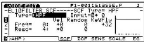
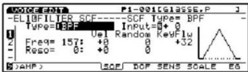
[F4]: SCF (Static Control Filter)
☐ Einstellungen: L/H Shelf (Low/High Shelving Filter), 2L Shelf (2-Low Shelving Filter), 2H Shelf (2-High Shelving Filter), LPF (Low Pass Filter), HPF (High Pass Filter), BPF (Band Pass Filter), InvertLPF (Inverted Low Pass Filter), PEQ (Parametric Equalizer), thru, boost 6dB/12dB/18dB
■ Input Gain
L/H Shelf (Low/High Shelving Filter)
![VOICE:OUT P1-001[GLASSE,P] -EL1BFILTER SCF----SCF Type= L/H Shelf- Type=DLZ+Shel Input=5+0 Freq--Vel Gain--Vel High: 131 +0 +0 +0 Low: 46 +0 +0 +0 (2)AMP SOF DOF SENS SCALE EG](/content/2026/05/776523/images/9b44445adae8bbebff3ba145361298e8b3c3341cafc1b1daacdbab7905692dc5.jpg)
■ High Freq (High Frequency)
■ Low Freq (Low Frequency)
■ High/Low Freq Vel (High/Low Frequency Velocity)
■ High/Low Gain Vel (High/Low Gain Velocity)
■ Low1/2 Freq (Low 1/2 Frequency)
■ Low1/2 Freq Vel (Low1/2 Frequency Velocity)
■ Low1/2 Gain Vel (Low 1/2 Gain Velocity)
line
| Freqenz | Value | | ------- | ----- | | High1 | 0 | | High2 | -1 |■ High1/2 Freq (High 1/2 Frequency)
■ High1/2 Freq Vel (High1/2 Frequency Velocity)
■ High1/2 Gain Vel (High 1/2 Gain Velocity)
LPF (Low Pass Filter)
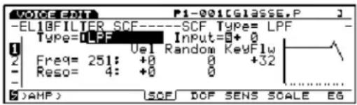
■ Freq Vel (Frequency Velocity)
■ Freq Random (Frequency Random)
■ Reso Vel (Resonance Velocity)
■ Reso Random (Resonance Random)
HPF (High Pass Filter)
BPF (Band Pass Filter)
InvertLPF (Inverted Low Pass Filter)
![VOICE EDIT P1-001[GCLASSE,P] -ELIBFILTER SCF------SCF Type= InvLPF - Type=InvLPF Input=0+0 Freq= 0: +0 Random KeyFlw Reso= 4: +0 0 +32 ( )AMP SOF DOF SENS SCALE EG](/content/2026/05/776523/images/3a9204e7061d13b85dc627465ea1dae1836bd3a493aefbf38870b200e402f643.jpg)
■ Freq Vel (Frequency Velocity)
■ Freq Random (Frequency Random)
■ Gain Vel (Gain Velocity)
☐ Einstellungen: LPF24A (Low Pass Filter 24A), LPF24D (Low Pass Filter 24D), LPF18 (Low Pass Filter 18), LPF12 (Low Pass Filter 12), LPF6 (Low Pass Filter 6), HPF (High Pass Filter), BPF (Band Pass Filter), BEF (Band Elimination Filter), thru
■ DCF2 Type (Filter 2 Type)
☐ Einstellungen: LPF (Low Pass Filter), BPF (Band Pass Filter), HPF (High Pass Filter), BEF (Band Elimination Filter)
■ Reso. Vel (Resonance Velocity)
■ DCF1/2 Reso (F1/2 Resonance)
LPF (Low Pass Filter)
line
| FreqenzGrenzfrequenz | Pegel | | ------------------- | ----- | | -6db/oct | 0 | | -12db/oct | 0 | | -18db/oct | 0 | | -24db/oct | 0 |LPF24A (Tiefpassfilter 24A):
line
| X | LPF12 | |---|---| | 0 | 0 | | Peak | High (approx) | | Decline | Low (approx) |LPF6 (Tiefpassfilter 6):
HPF (High Pass Filter)
BPF (Band Pass Filter)
[F6]: SENS (Sensitivity)
■ Atck Time Vel (Attack Time Velocity)
☐ Einstellungen: off, Hl (Hold), At (Attack), D1 (Decay 1)
■ Dcy 1/2 Level (Decay 1/2 Level)
■ Rel1/Rel2 Level (Release 1/2 Level)
■ Atck Time Vel (Attack Time Velocity)
■ Dcy1 Time Vel (Decay 1 Time Velocity)
■ Decay Level Vel (Decay Level Velocity)
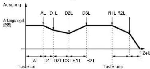
■ Init Level (Initial Level)
line
| Time Point | Ausgang | | :--- | :--- | | AL | Peak at D1T | | D1L | Peak at D2T | | D2L | Peak at D3T | | D3L | Peak at R1T | | R1L | Peak at R2T | | R2L | Peak at R2T | | AT | Taste an | | D1T | Taste an | | D2T | Taste an | | D3T | Taste an | | R1T | Taste an | | R2T | Taste an | | Taste aus | Taste aus | | 90 | 0 |Anfangspegel = Attack-Pegel
line
| Zeit | Ausgang | |---|---| | AL | 255 | | D1L | 255 | | D2L | 255 | | D3L | 255 | | R1L | 255 | | R2L | 255 | | Zelt | 0 |Attack-Modus 2
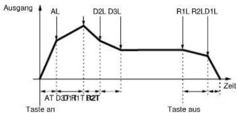
line
| Point | Time (Zeit) | Ausgang | |---|---|---| | AL | 0 | Peak | | D2L | 1 | Peak | | D3L | 2 | Peak | | R1L | 3 | Peak | | R2LD1L | 4 | Peak | | AT | 5 | Taste an | | D1R1T | 6 | Taste an | | B2T | 7 | Taste an | | Taste aus | 8 | Taste aus | Zeit at End[F6]: LFO (Low Frequency Oscillator)
[F7]: LFO1 (Low Frequency Oscillator1)
natural_image
Pure geometric line drawing with two triangles and a horizontal axis (no text or symbols)tri (Triangle)
![YAMAHA EX5R - [F7]: LFO1 (Low Frequency Oscillator1) - 1](/content/2026/05/776523/images/f72bf74a5a272d47381a9c090ef812c69f54cc336ef4009c18572f63f94596e2.jpg)
natural_image
Pure electrical circuit lines without any symbolssqu (Rechteck)
![YAMAHA EX5R - [F7]: LFO1 (Low Frequency Oscillator1) - 2](/content/2026/05/776523/images/e14389e53657a83ab3673651304b92da09b88ef1cd4437242b3fbceec2919071.jpg)
natural_image
Pure electrical circuit lines without any symbols■ Sync
line
| Zeit | Kleiner Wert | Großner Wert | |------|--------------|--------------| | 1 | Low | Low | | 2 | High | High | | 3 | Low | Low | | 4 | High | High | | 5 | Low | Low | | 6 | High | High | | 7 | Low | Low | | 8 | High | High | | 9 | Low | Low | | 10 | High | High | | 11 | Low | Low | | 12 | High | High | | 13 | Low | Low | | 14 | High | High | | 15 | Low | Low | | 16 | High | High | | 17 | Low | Low | | 18 | High | High | | 19 | Low | Low | | 20 | High | High | | 21 | Low | Low | | 22 | High | High | | 23 | Low | Low | | 24 | High | High | | 25 | Low | Low | | 26 | High | High | | 27 | Low | Low | | 28 | High | High | | 29 | Low | Low | | 30 | High | High | | 31 | Low | Low | | 32 | High | High | | 33 | Low | Low | | 34 | High | High | | 35 | Low | Low | | 36 | High | High | | 37 | Low | Low | | 38 | High | High | | 39 | Low | Low | | 40 | High | High | | 41 | Low | Low | | 42 | High | High | | 43 | Low | Low | | 44 | High | High | | 45 | Low | Low | | 46 | High | High | | 47 | Low | Low | | 48 | High | High | | 49 | Low | Low | | 50 | High | High | | 51 | Low | Low | | 52 | High | High | | 53 | Low | Low | | 54 | High | High | | 55 | Low | Low | | 56 | High | High | | 57 | Low | Low | | 58 | High | High | | 59 | Low | Low | | 60 | High | High | | 61 | Low | Low | | 62 | High | High | | 63 | Low | Low | | 64 | High | High | | 65 | Low | Low | | 66 | High | High | | 67 | Low | Low | | 68 | High | High | | 69 | Low | Low | | 70 | High | High | | 71 | Low | Low | | 72 | High | High | | 73 | Low | Low | | 74 | High | High | | 75 | Low | Low | | 76 | High | High | | 77 | Low | Low | | 78 | High | High | | 79 | Low | Low | | 80 | High | High | | 81 | Low | Low | | 82 | High | High | | 83 | Low | Low | | 84 | High | High | | 85 | Low | Low | | 86 | High | High | | 87 | Low | Low | | 88 | High | High | | 89 | Low | Low | | 90 | High | High | | 91 | Low | Low | | 92 | High | High | | 93 | Low | Low | | 94 | High | High | | 95 | Low | Low | | 96 | High | High | | 97 | Low | Low | | 98 | High | High | | 99 | Low | Low | | 100 | High | High | | 101 | Low | Low | | 102 | High | High | | 103 | Low | Low | | 104 | High | High | | 105 | Low | Low | | 106 | High | High | | 107 | Low | Low | | 108 | High | High | | 109 | Low | Low | | 110 | High | High | | 111 | Low | Low | | 112 | High | High | | 113 | Low | Low | | 114 | High | High | | 115 | Low | Low | | 116 | High | High | | 117 | Low | Low | | 118 | High | High | | 119 | Low | Low | | 120 | High | High | | 121 | Low | Low | | 122 | High | High | | 123 | Low | Low | | 124 | High | High | | 125 | Low | Low | | 126 | High | High | | 127 | Low | Low | | 128 | High | High | | 129 | Low | Low | | 130 | High | High | | 131 | Low | Low | | 132 | High | High | | 133 | Low | Low | | 134 | High | High | | 135 | Low | Low | | 136 | High | High | | 137 | Low | Low | | 138 | High | High | | 139 | Low | Low | | 140 | High | High | | 141 | Low | Low | | 142 | High | High | | 143 | Low | Low | | 144 | High | High | | 145 | Low | Low | | 146 | High | High | | 147 | Low | Low | | 148 | High | High | | 149 | Low | Low | | 150 | High | High | | 151 | Low | Low | | 152 | High | High | | 153 | Low | Low | | 154 | High | High | | 155 | Low | Low | | 156 | High | High | | 157 | Low | Low | | 158 | High | High | | 159 | Low | Low | | 160 | High | High | | 161 | Low | Low | | Note: The actual values for Kleiner Wert and Großner Wert are not provided in the code. The data is presented as a table with two columns: 'Zeit' and 'Zeit'.■ AMD (Amplitude Modulation Depth)
■ PMD (Pitch Modulation Depth)
[F8]: LFO2 (Low Frequency Oscillator 2)
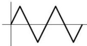
■ Wave
natural_image
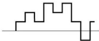
Simple sine wave waveform diagram with no text or labelstri (triangle wave; Dreieckswelle)
natural_image
Pure electrical circuit lines without any symbolsnatural_image
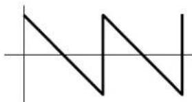
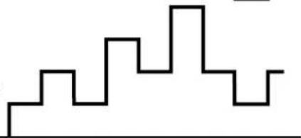
Pure geometric line drawing with two triangles and a horizontal axis (no text or symbols)saw d (saw down wave; Sägezahnwelle, abwäats)
natural_image
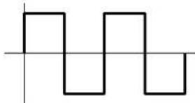
Pure geometric line drawing with two triangles and a horizontal axis, no text or symbols presentsqu (square wave; Rechteck welle)
natural_image
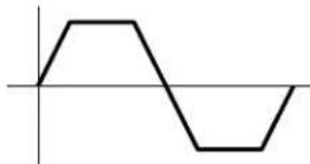
Pure electrical circuit lines without any symbolstrpzd (trapezoid wave; Trapezwelle)
natural_image
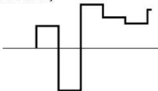
Simple line drawing of a waveform with no text or symbolss/h 1 (sample & hold1)
natural_image
Abstract geometric line drawing with no text or symbolss/h 2 (sample & hold2)
natural_image
Abstract black line drawing on white background with no text or symbols■ Sync
line
| Phase | Zeit | |---|---| | 0° | 0 | | 90° | 1 | | 180° | 2 | | 270° | 3 | | (Note: The chart displays a single data point at 270°) and is not explicitly labeled in the provided image. The axis labels are 'Wert' and 'Phase', but the values for 'Zeit' are estimated based on the label '0'.)■ Dest (Destination)
[F7]: CTRL (Controller)
[F7]: PITCH (Pitch Control)
[F8]: SET (Controller set)
![YAMAHA EX5R - [F8]: SET (Controller set) - 1](/content/2026/05/776523/images/b76abed21168bc7688975ebae599a5b34a1e94de1a43295a20c7f593ce9d9672.jpg)
flowchart
graph LR
    A["Controller\nTastatur,\nModulations-Handrad,\nKnöpfe, usw."] --> B["Voice Control 1~16\nSatz 1\n...\nSatz 16"]
    B --> C["Elemente\n1\n2\n3\n4"]
■ Ctrl (Controllers)
[F8]: EFCT (Effects)
■ ① InsEF Elem Sw (Insertion Effect Element Switch)
■ ②InsEF Connect (Insertion Effects Connect)
■⑤Rev Send (Reverb Send)
■ ⑨ Cho → Rev (Chorus → Reverb)
■⑩Rev Pan (Reverb Pan)
[F5]: INS1 (Insertion 1)
[F6]: INS2 (Insertion 2)
[F2]: OSC (Oscillator)
[F6]: WAVE
![VOICE-REF P1-114[Marcus*] -ELI-PITCH Param ----Coarse Tunem -12- Coarse Fine Detune VeLEG EQDpth EGRndm 0-12 -- 0+0 -- --- 2: +0 +0 +0 +0 +63 0 --- --- --- --- --- ( >FLTR ) (PARAM SCALE EG](/content/2026/05/776523/images/a60ba40704c7665504728129c6e902643f8af573d6d061a71b5c71568e0ff3f7.jpg)
■ Bank
[F3]: PITCH (Pitch Parameters)
[F6]: PARAM (Parameters)
[F7]: SCALE
[F8]: EG (Pitch Envelope Generator)
[F7]: EQ (Equalizer)
■ EQ1 \~ EQ5 Freq (EQ1 \~ EQ5 Frequency)
[F8]: DCF (Dynamic Control Filter)
![VOICE EDIT PI-114[Marcus*] -ELI•FILTER DCF--------Resonance= + 0- Resonance Freq: EGDepth KeyFWI--BP + 0 0+ 0 0+ 0 0+ 0 0C -2 J >AMP > ED](/content/2026/05/776523/images/d4cab64ce6f78d58505c4ae5c377aa9381287137f3ff65daabc938e817992960.jpg)
■ Resonance
■ Cutoff Freq (Cutoff Frequency)
■ Freq K.Follow (Frequency Key Follow)
■ Freq K.Flw BP (Frequency KeyFollow Break Point)
[F8]: EG (Envelope Generator)
[F6]: LFO (Low Frequency Oscillator)
[F8]: LFO (Low Frequency Oscillator)
[F7]: CTRL (Controller)
Normal Voice (AN Element)
[F3:Algorithm]....113
[F4:VCO]....114
[F5:Modulation]....116
[F6:Wave] 116
[F7:Mix]....81
[F8:Zone] 82
[F3:PTCH]....117
[F6:Parameter] 83
[F7:Scaling] 83
[F8:EG] 117
[F4:FILTER]....118
[F7:VCF]....118
[F8:EG] 119
[F5:AMPLITUDE]......119
[F6:Parameter] 96
[F7:Mixing] 119
[F8:EG]....120
[F6:LFO] 121
[F8:LFO]....121
[F7:CONTROLLER]....123
[F7:Pitch Control] 103
[F8:Controller Set] ......123
[F8: EFFECT] 105
[F4:Type] 105
[F5:Insertion Effect 1] ......106
[F6:Insertion Effect 2] ......106
[F7:Reverb]....107
[F8:Chorus]....107
[F2]: OSC (Oscillator)
flowchart
graph TD
    A["Master of VCO1\nVCO2\nLFO1, 2\nEG, etc."] -->|FM| B["Master of VCO1\nSlave VCO1"]
    A -->|Sync| C["Master of VCO1\nSlave VCO1"]
flowchart
graph TD
    A["Master of VCO1\nVCO2\nLFO1, 2\nEG, etc."] --> B["FM"]
    C["Master of VCO1"] --> D["Sync\nGlove\nVCO1"]
    D --> B
Sync
FM (Frequenz Modulation)
■ FM Src (FM Source)
[F4]: VCO (Voltage Controlled Oscillator)
■ VCO1/2 Freq Fine (VCO1/2Frequency Fine)
VCO2: saw, pulse, saw2, mix
saw (Sägezahnwelle)
Innr1 (Inner1: Inner1)
Innr2 (Inner2: Inner2)
Innr3 (Inner3: Inner3)
natural_image
Three waveforms showing periodic oscillations with no text or labels[F5]: MOD (Modulation)
■ VCO1/2 Mod (VCO1/2Modulation)
■ VCO1 ModSw (VCO1 Modulation Switch)
[F3]: PITCH (Pitch Parameters)
[F6]: PARAM (Parameters)
[F7]: SCALE
[F8]: EG (Envelope Generator)
[F7]: VCF (Voltage Controlled Filter)
![VOICEFHT P1-127[RESBASSCOMP J] -EL10FILTER VCF------Resonance= 0- 1 Resonance Freqt EGDepth KeyFlw Vel 2 8 3 0100 0+ 32 0+ 0 0+ 0 - FilterType HPF - LPF24 0 ( >AHP ) VCF ES](/content/2026/05/776523/images/dcfc7ed5e76b8dd0002711b8bc7dfefdbfb2ffe90d8c7ee119e1a134aae63a58.jpg)
■ Cutoff Freq (Cutoff Frequency)
■ HPF Freq (High Pass Filter Cutoff Frequency)
■ Freq Vel Sens (Frequency Velocity Sensitivity)
■ Time K.Follow (Time KeyFollow)
■ Time K.Follow (Time KeyFollow)
[F6]: LFO (Low Frequency Oscillator)
[F8]: LFO (Low Frequency Oscillator)
■ LFO1 Wave (Low Frequency Oscillator1 Wave)
☐ Einstellungen: sine, sine†, sine††, sine180†, sine180††, tri, trit, tri††, tri180†, tri180††, squ, squ††, aqu180†, saw dwn, saw dwn††, saw up, saw up††, s/h, s/h††, s/h2, s/h2††
natural_image
Abstract geometric line pattern with irregular step-like shapes and a horizontal baseline (no text or symbols)s/h2 ↑↑
natural_image
Abstract black line drawing on white background with no text or symbols■ LFO1 Delay
■ LFO1 FMD (LFO1Frequency Modulation)
■ LFO2 Wave (Low Frequency Oscillator 2 Wave)
[F7]: CTRL (Controller)
[F8]: SET (Controller Set)
FDSP (Formulated Digital Sound Processing)
■ ElmSw (Element Switch)
| ☐ Einstellungen: 01: EP Pickup (Electric Piano Pickup) |
| 02: EG Pickup (Electric Guitar Pickup) |
| 03: Water |
| 04: PWM (Pulse Width Modulation) |
| 05: Flange |
| 06: Phaser |
| 07: Self FM |
| 08: Tornado |
| 09: Ring Mod (Ring Modulator) |
| 10: Seismic |
01: EP Pickup (Electric Piano Pickup)
different (differentiate):
■ Drive K.Flw (Drive KeyFollow)
■ BP Low (Break Point Low)
■ BP High (Break Point High)
■ Pos High Kf (Position High KeyFollow)
■ Pos Hmid Kf (Position High Mid KeyFollow)
■ Pos Low Kf (Position Low KeyFollow)
■ Out High Kf (Out High KeyFollow)
■ HPF (High Pass Filter)
■ HPF K.Flw (High Pass Filter KeyFollow)
■ Freq K.Flw (Frequency KeyFollow)
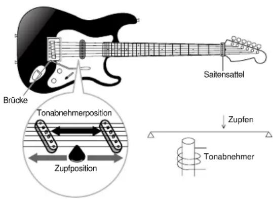
02: EG Pickup (Electric Guitar Pickup)
flowchart
graph TD
    A["Input"] --> B["Delay Delay"]
    B --> C["Buffer"]
    C --> D["picking notch"]
    D --> E["pickup notch"]
    E --> F["Picking position Pickup Position"]
    F --> G["Drive"]
    G --> H["Integ"]
    H --> I["Magnetic Field"]
    I --> J["Diff"]
    J --> K["Emp"]
    K --> L["HPF"]
    L --> M["LPF"]
    M --> N["Output"]
    O["Flet control"] --> B
    P["Note dependent note dependent"] --> B
    Q["Distance"] --> H
    R["Pickup type"] --> J
    S["Highpass"] --> L
    T["Cutoff/Resonance"] --> M
    U["Filter bypass"] --> M
natural_image
Technical line drawings of two types of electric shock absorbers (no text or symbols on the diagrams)■ Coarse
■ Picking Pos (Picking Position)
■ Picking P Kf (Picking Position KeyFollow)
■ Pickup Pos (Pickup Position)
■ Pickup P Kf (Pickup Position KeyFollow)
■ Output KFlw (Output KeyFollow)
■ HPF (High Pass Filter)
■ HPF K.Flw (High Pass Filter KeyFollow)
■ Freq K.Flw (Frequency KeyFollow)
■ Freq Mod (Frequency Modulation)
■ Mod Speed (Modulation Speed)
■ Mod Smooth (Modulation Smooth)
■ High Dump Kf (High Dump KeyFollow)
■ HPF (High Pass Filter)
■ LFO Mode (Low Frequency Oscillator Mode)
■ LFO Depth (Low Frequency Oscillator Depth)
■ LFO Speed (Low Frequency Oscillator Speed)
■ LFO Wave (Low Frequency Oscillator Wave)
■ LFO Phase (Low Frequency Oscillator Phase)
line
EG- Pegel | Label | Value | |---|---| | Top Right | High | | Bottom Right | Low |line
| EG-Pegel | Value | | -------- | ----- | | Low | 0 | | Medium | High | | High | Very High |■ Decay T.Kf (Decay Time KeyFollow)
■ Sustain Lvl (Sustain Level)
■ LFO Depth (Low Frequency Oscillator Depth)
■ LFO Speed (Low Frequency Oscillator Speed)
■ LFO Depth (Low Frequency Oscillator Depth)
■ LFO Speed (Low Frequency Oscillator Speed)
■ Drive K.Flw (Drive KeyFollow)
■ LPF (Low Pass Filter)
■ LPF K.Flw (Low Pass Filter KeyFollow)
■ Wet Vel (Wet Level Velocity)
■ Dry Vel (Dry Level Velocity)
■ Pre LPF (Low Pass Filter)
■ HPF (High Pass Filter)
■ HPF K.Flw (High Pass Filter KeyFollow)
■ LPF (Low Pass Filter)
■ LPF K.Flw (Low Pass Filter KeyFollow)
■ Wet Vel (Wet Level Velocity)
09: Ring Mod (Ring Modulator)
■ Drive Vel (Drive Velocity)
■ Drive K.Flw (Drive KeyFollow)
■ Decay T.Kf (Decay Time KeyFollow)
■ Sustain Lvl (Sustain Level)
■ HPF (High Pass Filter)
■ HPF K.Flw (High Pass Filter KeyFollow)
■ Output (Output Level)
[F7]: Ctrl (Controller)
[F8]: SET (Controllersatz)
[F2]: OSC (Oscillator)
■ Recv Note Off (Receive Note Off)
■ Rev Send (Reverb Send)
[F6]: LFO (Low Frequency Oscillator)
[F8]: LFO (Low Frequency Oscillator)
■ Wave
■ PMD (Pitch Modulation Depth)
[F7]: Ctrl (Controller)
[F8]: SET (Controller Set)
[F8]: EFCT (Effects)
[F1]: Init Voice (Initialize Voice)
■ ④Types of Source Data
■ LpLength (Loop Length)
■ Freq Mode (Frequency Mode)
■ Wave
①Anzeige-Titel
④Performance Category/name
■ Performance Category
PART-MENÜ
![PERFORM EDIT PERF=001[Init Perform] MID1=P1-001[GlassE.P KBD 1ch MIDI 0 8 8 8 A-MIDI-B ARF TG Layer Sw= on Nt Limit= C 2-G 8 VelLimit= 1-127 VelCurve=0norm Sens/Ofs= 64/+ NoteShift= + 0 COH |PART| HLT HIX LVR SOUND CTRL PRE F1 F2 F3 F4 F5 F6 F7 F8](/content/2026/05/776523/images/22aa81d10cb1201feacb7d23ed15c0332739774ea0075ee14dd63b777e8eda26.jpg)
■ Total Volume
[F5]: ARP-EDIT (Arpeggio Edit)
■ Arp Sw (Arpeggio Switch)
■ ①Rev Type (Reverb Type)
■ ③ Cho → Rev (Chorus → Reverb)
■④Rev Pan (Reverb Pan)
[F7]: CTRL (Controller)
| F6:WHEEL | PB (Pitch Bend Wheel)RC (Ribbon Controller)MW1 (Modulation Wheel 1)MW2 (Modulation Wheel 2) |
| F7:KNOB | KN1 (Knobs 1)KN2 (Knobs 2)KN3 (Knobs 3)KN4 (Knobs 4)KN5 (Knobs 5)KN6 (Knobs 6) |
| F8:OTHER | AT (Attack Touch)FC (Foot Controller)BC (Breath Controller) |
■ Part
□ Einstellungen: L, 1 \~ 16

■ Rev Send (Reverb Send)
■ ⑥MIDI to TG (MIDI to Tone Generator)
■ VelCurve (Velocity Curve)
Vel Sens (Velocity Sensitivity):
PEG (Pitch Envelope Generator)
■ PEG RelL (PEG Release Level)
[F7]: CTRL (Controllers)
■ Trns Sw (Transmission Switch)
Bank/PC:MD (Bank/Program Change: MIDI)
■ Ctrl To TG (Controller To Tone Generator)

[F1]: Init Perform (Initialize Performance)
[F2]: Recall Perform (Recall Performance)
[F3]: Copy Perform (Copy Performance)
■ ③Types of Source Data
■ Rec Mode (Record Mode)
■ Fraction (Loop Fraction)
■ Src Sample (Source Sample Bank)
□ Settings: DRAM, FLS (FLASH)
■ Src Sample (Source Sample Number)
■ Src Sample (Source Sample Bank)
□ Settings: DRAM, FLS (FLASH)
■ Src Sample (Source Sample Number)
■ Src1 Sample (Source 1 Sample Number)
■ Src2 Sample (Source 2 Sample Number)
[F4]: Normalize Sample
■ Src Sample (Source Sample Number)
[F5]: Extract Sample
■ Src Sample (Source Sample Number)
■ Measure/SONG (Song Name)
[F2]: PFX (Play Effects)
■ Str (Quantize Strength)
bar
Velocity Offset = -20 | Velocity | (Vel) | | :--- | :--- | | 76 | 1.5 | | 44 | 1.8 | | 12 | 1.3 | | 107 | 0.5 | | 76 | 2.0 | | (Note: The 'Vel' label is not present in the image, so it's a possible label for the bars.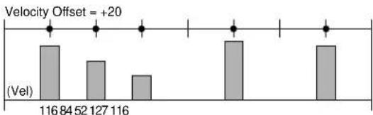
bar
| Velocity Offset | (Vel) | | :--- | :--- | | 116 | 84 | | 52 | 127 | | 116 | 116 | Velocity Offset = +20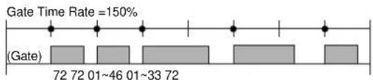
☐ Einstellungen: 0% \~ 100% \~ 200%
[F3]: TCH (Transmit Channel)
■ T-Ch (Transmit Channel)
[F4]: NAME (Song Name)
[F6]: OVER (Over Dubbing)
[F7]: RPLC (Replace)
[F8]: PNCH (Punch In)
Step Recording: Tr1\~Tr16
■ Location (Measure, Beat, Clock)
ppp (8), pp (24), p (40), mp (56), norm (64), mf (72), f (88), ff (104), fff (120)
![SONG REC M001 SONG: [Init Song] Tr1 0001-05-000 5/4 1098 mf@Norm 2↓---1 REST TIE DEL BKDEL (-KEY-)](/content/2026/05/776523/images/95ccbd424fd64b635aa7812cc4228aba4f2ef4d95800be45a4b217ae5ed3c7e7.jpg)
Beispiel 2
Keyboard Illustration
■ [F1]/[F2]/[F3]/[F4]: REST/TIE/DEL (Delete)/BKDEL (Back Delete)
■ CAT (Channel After Touch)
■ PAT (Polyphonic After Touch)
[F2]: PFX (Pattern Play Effects Track)
[F3]: PTN (Pattern Track)
2. Copy Track
■ Src Track (Source Track)
■ Track
■ Src Track (Source track)
■ Dst Track (Destination track)
■ Track
■ Track
■ Src Track (Quellenspur)
■ Src Meas (Source Measure)
■ Track
■ Measure
■ Measure
■ Track
☐ Program Change, Control Change (Control number), Ch After Touch, PolyAfterTouch: 0 \~ 127
□ Pitch Bend: -8192 \~ +8192
7. Chord Sort
■ Streng (Quantize Strength)
■ Vel (Swing Velocity)
STEMIH
bar
| Category | Gate Count | | :--- | :--- | | Originaldaten | 32 | | (Gate) | 32 | | (Gate) | 32 | | (Gate) | 48 | | (Gate) | 48 | | (Gate) | 48 | | Austastzeit-Rate=50% | 16 | | (Gate) | 16 | | (Gate) | 16 | | (Gate) | 24 | | (Gate) | 24 | | (Gate) | 24 | | Austastzeit-Rate=150% | 48 | | (Gate) | 48 | | (Gate) | 48 | | (Gate) | 72 | | (Gate) | 72 |☐ Einstellungen: 000% \~ 100% \~ 200%
■ Offset
■ Track
■ Track
■ Track
■ Track
■ Src Event (Source Event)
■ Dst Event (Destination Event)
■ Measure/PTN (Pattern Name)
■⑧Metronome (Click) Beat
[F2]: PFX (Play Effects)
![YAMAHA EX5R - [F2]: PFX (Play Effects) - 1](/content/2026/05/776523/images/fa1f0df3f50ef0cad3a93b4bc839866ed2767314e5743af7e11908648d3dbb5c.jpg)
■ Length (Loop Length)
[F3]: TCH (Transmit Channel)
■ T-Ch (Transmit Channel)
[F4]: NAME (Pattern Name)
[F6]: OVER (Over Dubbing)
[F7]: RPLC (Replace)
-F7:UNDO]....237
■ Ptn
■ Src Pth (Source Pattern)
■ Src Trk (Source Track)
■ Track
■ Src Track (Source track)
■ Dst Track (Destination track)
■ Src Ptn (Source Pattern)
■ Src Track (Source Track)
■ Src Ptn (Source Pattern)
■ Src Track (Source Track)
■ Track
■ Src Track (Source Track)
■ Src Meas (Source Measure)
■ Track
■ Src Song Track (Source Song Track)
■ Src Ptn (Source Pattern)
■ Track (Source Track)
■ Track
■ Track
☐ Program Change, Control Change (Control number), Ch After Touch, PolyAfterTouch: 0 \~ 127
□ Pitch Bend: -8192 \~ +8192
7. Chord Sort
■ Track
■ Track
■ Streng (Quantize Strength)
□ Einstellungen: 0% \~ 100%
■ Vel (Swing Velocity)
☐ Einstellungen: 0% \~ 100% \~ 200%
■ Gate (Swing Gate Time)
☐ Einstellungen: 0% \~ 100% \~ 200%
2. Move Clock
■ Src Event (Source Event)
■ Dst Event (Destination Event)
■ Measure/ARP (Arpeggio Type Name)
[F2]: PFX (Play Effects)
Track Section
[F4]: NAME (Arpeggio Type Name)
[F6]: OVER (Over Dubbing)
[F7]: RPLC (Replace)
■ Src Arp (Source Arpeggio)
■ Src Arp (Source Arpeggio)
■ Src Track (Source Track)
Track
■ Src Track (Source Track)
■ Src Arp (Source Arpeggio)
■ Src Track (Source Track)
■ Src Arp (Source Arpeggio)
■ Src Track (Source Track)
■ Track
■ Src Trk (Source Track)
■ Src Meas (Source Measure)
■ Track
■ Src Song Track (Source Song Track)
■ Track
■ Track
☐ Note: Key = 1 \~ 16, Oct = -4 \~ +3
☐ Program Change, Control Change (Control number), Ch After Touch, PolyAfterTouch: 0 \~ 127
□ Pitch Bend: -8192 \~ +8192
■ Track
■ Track
■ Streng (Quantize Strength)
□ Einstellungen: 0% \~ 100%
■ Vel (Swing Velocity)
☐ Einstellungen: 0% \~ 100% \~ 200%
■ Gate (Swing Gate Time)
□ Einstellungen: 0% \~ 100% \~ 200%
2. Move Clock
HIYWEI
HINWEI
GEMLUH
■ Src Event (Source Event)
■ Dst Event (Destination Event)
1 Performance, 1 Voice
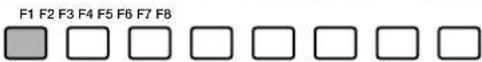
F1 F2 F3 F4 F5 F6 F7

Grundmenü
[F7]: NAME (File Name)
[F8]: DIR (Directory)
[F1]: SAVE (File Save)
[F2]: LOAD (File Load)
[F3]: RNAM (File Rename)
[F5]: MKDIR (Make Directory)
[F1]: SYN (Synthesizer Setup)
■ Master Volume
■ Keyboard Transpose
Modulation Wheel (Modulations-Handrad): Minimum
After Touch: Minimum
■①Global Recv Ch (Global Receive Channel)
■ VelCurve (Velocity Curve)
| PB (Pitch Bend Wheel) |
| RC (Ribbon Controller) |
| MW1 (Modulation Wheel 1) |
| MW2 (Modulation Wheel 2) |
| KN1 (Knobs 1) |
| KN2 (Knobs 2) |
| KN3 (Knobs 3) |
| KN4 (Knobs 4) |
| KN5 (Knobs 5) |
| KN6 (Knobs 6) |
| AT (After Touch) |
| FC (Foot Controller) |
| BC (Breath Controller) |
[F3]: SEQ (Sequencer Setup)
[F6]: CLICK (MIDI Click)
■ Channel
Ch. AT (Channel After Touch; Kanal-After Touch)
PolyAT (Polyphonic After Touch; Poluphoner After Touch)
Note
■ Event Chase
■ Global Recv Ch (Global Receive Channel)
■ Receive Pgm Chng (Receive Program Change)
[F5]: CTRL (Controller Setup)
[F6]: OTHER (Other Setup)
☐ Einstellungen: internal (EX = master), external (EX = slave)
[F7]: MSG (Greeting Message)
natural_image
Diagram of a hand pressing down on a panel with an arrow indicating motion (no text or symbols present)natural_image
Diagram of a hand pressing down on a component with an arrow indicating force (no text or symbols present)natural_image
Architectural floor plan sketch showing room layouts and structural elements (no text or labels)natural_image
Illustration of a hand inserting a component into a device, showing a downward arrow (no text or symbols present)natural_image
Line drawing of a device with a hand inserting a component into a box (no text or symbols)AN(Poly) + AWM Voices 34
AN-Synthese (Analog Physical Modeling) 33
Bank/PC:MD (Bank/Program Change: MIDI) 170
Beat Number 221
Beat Graph 199
BP High (Break Point High) 125
BP Low (Break Point Low) 124
BP1\~4 Level(Pegel) 97
CAT (Channel After Touch) 203
Cat(Category) 81
CC (Control Change) 202
Ceiling 137
Center Key 83
Center Key (Center-Schalter) 179
Channel 272
Cho (Chorus) 106, 107, 162
Cho Pan (Chorus Pan) 106, 162
Cho Return (Chorus Return) 106, 162
Cho Send (Chorus Send) 106, 145, 165
Cho Type (Chorus Type) 162
Cho → Rev (Chorus → Reverb) 106, 162
Chord Separate 211, 234, 255
Chord Sort 211, 233, 255
Chorus 65
Clear Arp 250
Clear Arpeggio 250
Clear Pattern 229
Clear Song 207
Clear Track 208, 229, 251
Click (Click-Modus) 220, 239
Click (Metronome) (Click-Modus) 186
Click (Metronome) Beat 186
CLICK (MIDI Click) 272
Clk (Clock Shift) 189
ClkSft (Clock Shift) 191
Clock 211, 215, 234, 235, 255, 256
Clock Number 222
Coar (Coarse Tune) 153
Coarse 127
Coarse Tune 83,144
COM (Common) 77, 107, 112, 123, 142, 159
COM-MENU 158
Connect 92, 271
Contents 7
Controller 170
Controller Reset 271
Copy Measure 209, 231, 253
Copy Pattern 229
Copy Perform (Copy Performance) 173
Copy Sample 183
Copy Track 208, 229, 251
Copy Voice 149
Copy Wave 155
Create Measure 209
Crescendo 217, 236, 258
CTRL (Controller Setup) 275
CTRL (Controller) 103, 111, 123, 147, 163, 272
Ctrl (Controllers) 104, 169
Ctrl to MIDI (Contoroller To MIDI) 170
Ctrl To TG (Controller To Tone Generator) 170
Ctrl(Controller) 141
Current Voice 150
Curve 163,272
Cutoff Freq (Cutoff Frequency) 110, 118
D
DCF (Dynamic Control Filter) 91, 110
DCF1 Type (Filter 1 Type) 91
DCF1/2 EG (F1/2 EG) 92
DCF1/2 Freq (F1/2Frequency) 91
DCF1/2 Gain 91
DCF1/2 LFO (F1/2 LFO) 92
DCF1/2 Reso (F1/2 Resonance) 92
DCF2 Type (Filter 2 Type) 91
Dcy 1/2 Level (Decay 1/2 Level) 85, 96
Dcy 1/2 Time (Decay 1/2 Time) 85, 96
Dcy 1-3 Level 99
Dcy 1\~3 Time (Decay 1-3 Time) 99
Dcy1 Time Vel (Decay 1 Time Velocity) 98
Decay Level Vel (Decay Level Velocity) 99
Decay T.Kf (Decay Time KeyFollow) 133, 140
Decay Time 111, 119, 120, 133, 137, 140, 168
DEL (Delete) 268
Delay 100, 103
Delete Measure 210
Delete Sample 183
Delete Wave 155
Depth 103, 163, 272
Der Arpeggiator 61
Effect Bypass 67,276
EG (Pitch Envelope Generator) 84, 109
EG Depth 83
EG Depth (Envelope Generator Depth) ...... 132, 134, 137
EG Depth Vel
(Envelope Generator Depth Velocity) ...... 132, 134, 137
EG Mode (Envelope Generator Mode) .... 131, 134, 136, 139
EG Pickup (Electric Guitar Pickup) 126
EG Random 83
EG Shape (Envelope Generator Shape) 131
EG Time (Envelope Generator Time) ..... 131, 134, 136, 139
EG Time Kflw
(Envelope Generator Time KeyFollow) .... 132, 134, 136, 139
High1/2 Freq Vel (High1/2 Frequency Velocity) 87
High1/2 Gain 88
High1/2 Gain Vel (High 1/2 Gain Velocity) 88
HPF (High Pass Filter) ..... 89, 93, 125, 128, 129, 137, 141
HPF Freq (High Pass Filter Cutoff Frequency) 118
HPF K.Flw (High Pass Filter KeyFollow) .... 126, 128, 137, 141
I
Index 296
Init Level (Initial Level) 99
Init Performance (Initialize Performance) 173
Init Voice (Initialize Voice) 149
Initial Level 109
InitVal KN1\~6 (Initial Values KN1\~6) 171
InitVal MW1/MW2/AT/FC/BC/RB (Initial Values) 170
InitVal PB (Initial Value Pitch Bend) 170
Input Gain 86
Input Level 140
Input Level Bar 176
Ins → Cho 148
Ins → Rev 148
INS1 (Insertion 1) 106
INS2 (Insertion 2) 106
InsEF Connect (Insertion Effects Connect) 105
InsEF Elem Sw (Insertion Effect Element Switch) .. 105, 146
InsEF Sw (Insertion Effect Switch) 165
InsEF1 (Insertion Effect 1) 106
InsEF2 (Insertion Effect 2) 106
Insertion-Effekte 6
InvertLPF (Inverted Low Pass Filter) 89
J
JOB1 207,228,250
JOB2 209, 231, 252
JOB3 212, 234, 255
K
K.Flw Coarse (KeyFollow Coarse) 138
K.Flw Fine (KeyFollow Fine) 138
Kbd/TG Mode (Keyboard/Tone Generator-Modus) .... 160, 271
Key 24
Key Assign 79,146,165
Keyboard Illustration 200
Keyboard Transpose 270
KeyFollow 83, 128, 130, 132, 134, 135
KeyOn Delay 81, 108, 144
Knob 17
Knob To MIDI 171
Knob To TG (Knob To Tone Generator) 171
Kopfhörer 1
L
L (Loop) 85
L(Loop) 96
L/H Shelf (Low/High Shelving Filter) 86
Length (Loop Length) 221
Level 81, 96, 145
Level K.Flw BP (Level Key Follow Break Point) 110
Level K.Follow (Level Key Follow) 110
Level KeyFollow 97
Level Vel (Level Velocity) 97, 145
LFO (Low Frequency Oscillator) 100, 111, 121, 147
LFO Depth (Low Frequency Oscillator Depth) .... 131, 133, 134
LFO Mode (Low Frequency Oscillator Mode) 130
LFO Phase (Low Frequency Oscillator Phase) 131
LFO Speed (Low Frequency Oscillator Speed) 131, 133, 134
LFO Wave (Low Frequency Oscillator Wave) 131
LFO1 (Low Frequency Oscillator1) 100
LFO1 AMD (LFO1 Amplitude Modulation) 123
LFO1 Delay 123
LFO1 FMD (LFO1Frequency Modulation) 123
LFO1 Speed 123
LFO1 Sync 123
LFO1 Wave (Low Frequency Oscillator1 Wave) 121
LFO2 (Low Frequency Oscillator 2) 102
LFO2 Speed 123
LFO2 Wave (Low Frequency Oscillator 2 Wave) ..... 123
LOAD (File Load) 265
Local (MIDI Control Out) 275
Location (Measure, Beat, Clock) 198
LOOP 181, 186
Loop End 181
Loop Length 180
Loop Length Offset 144
Loop Start/End Point 186
Loop Top 180
LoopTune 179
Low 1/2 Gain Vel (Low 1/2 Gain Velocity) 87
Low Freq (Low Frequency) 86
Low1/2 Freq (Low 1/2 Frequency) 87
Low1/2 Freq Vel (Low1/2 Frequency Velocity) 87
Low1/2 Gain 87
LPF (Low Pass Filter) 88, 92, 135, 137
LPF K.Flw (Low Pass Filter KeyFollow) 136, 137
LpLength (Loop Length) 152
Lvl (Level) 153
LYR (Layer) 165
M
M.FreqCoarse (Main Frequency Coarse) 139
M.FreqFine (Main Frequency Fine) 139
M.Mod Depth (Main Modulation Depth) 139
M.Mod EG (Main Modulation Envelope Generator) ..... 139
M.Mod EG Vel (Main Modulation Envelope Generator
velocity) 139
Master Note Shift 270
Master Tune 270
Master Volume 270
MaxLng (Maximum Length) 220
MD BankLSB (MIDI Bank Select LSB) 170
MD BankMSB (MIDI Bank Select MSB) 170
Measure..186, 194, 208, 210, 211, 212, 215, 216, 217, 218,
220, 224, 230, 231, 232, 233, 234, 235, 236, 237, 239, 246, 250, 253, 254, 255, 256, 257, 258
232, 250, 254, 255, 256, 257, 258
Measure Number 221
Measure/ARP (Arpeggio Type Name) 238
Measure/PTN (Pattern Name) 219
Measure/SONG (Song Name) 185
MIDI to TG (MIDI to Tone Generator) 166
MIDI Trans Ch (MIDI Transmit Channel) 271
MIDI Trns Ch 274
MIDI-A/MIDI-B (MIDI OUT A/B) 192, 222
MIDI-Anschlüsse 22
MOD (Modulation) 116
Mod Smooth (Modulation Smooth) 129
Mod Speed (Modulation Speed) 129
MODE 24
Modify GateTime 215, 235, 256
Modify Velocity 216, 235, 257
Mono/Poly 79
Mono/Poly (Monophonic/Polyphonic) 165
Move Clock 214, 235, 256
MSG (Greeting Message) 277
MTC Start Offset (MTC Start Offset) 274
MULTI 195,224
NAME (Arpeggio Type Name) 244
NAME (File Name) 262
NAME (Pattern Name) 222
NAME (Song Name) 192
No (Pattern Number) 220, 224
Noise Level 120
Normal Voice (AN Element) 112
Normal Voice (AWM Element) 77
Normal Voice (VL Element) (nur EX5/5R) 107
Out High Kf (Out High KeyFollow) 125
Out Hmid Kf (Out High Mid KeyFollow) 125
Out Level (Output Level) 125
Out Lmid Kf (Out Low Mid Keyfollow) 125
Out Low Kf (Out Low KeyFollow) 125
Out Select (Output Select) 164
Output 128
Output (Output Level) 141
Output KFlw (Output KeyFollow) 128
OVER (Over Dubbing) 195, 224, 246
Overdrive 141
PAT (Polyphonic After Touch) 203
Pattern 186
Pattern Edit-Modus 226
PEG (Pitch Envelope Generator) 168
PEG Atck (PEG Attack) 168
PEG Decay Time 118
PEG Depth 117
PEG Depth (Pitch Envelope Generator Depth) 139
PEG DepthVel
(Pitch Envelope Generator Depth Velocity) 139
PEG Init (PEG Initial) 168
PEG Mode 117
PEG ReIL (PEG Release Level) 168
PEG ReIT (PEG Release Time) 168
PEQ (Parametric Equalizer) 90
Performance Category 157
Picking P Kf (Picking Position KeyFollow) 127
Picking Pos (Picking Position) 127
PickingNotch 127
Pickup Notch 127
Pickup P Kf (Pickup Position KeyFollow) 127
Pickup Pos (Pickup Position) 127
Pickup Type 124, 127
PITCH 83,111,146
PITCH (Pitch Control) 103
PITCH (Pitch Parameters) 108, 117
Pitch Bend Lower 103,169
Pitch Bend Upper 103, 169
Pitch Coarse 128, 130, 132, 133, 135, 138
Pitch EG Depth 144
Pitch EG VelSens (PEG Velocity Sensitivity) 144
Pitch Fine 128, 132, 138
PLAY 26
Play Effect Thru 220
Play Effects & Groove Quantization 64
Play Effects Thru 185, 239
Play Mode 175
PMD (Pitch Modulation Depth) 102, 147
PNCH (Punch In) 195
Polarity 13
Polyphonie 45,78
Port (Portamento) 169
Port Mode (Portamento Mode) 104, 169
Port Sw (Portamento Switch) 103, 169
Port Time (Portamento Time) 103.169
Pos High Kf (Position High KeyFollow) 125
Pos Hmid Kf (Position High Mid KeyFollow) 125
Pos Lmid Kf (Position Low Mid KeyFollow) 125
Pos Low Kf (Position Low KeyFollow) 125
Position 125
Post EQ 109
PRE (Preset) 170
Pre Gain 136
Pre LPF (Low Pass Filter) 136
PTN (Pattern Track) 205
PTN (Pattern) 219, 223, 261, 264, 267
Ptn No (Pattern Number) 194
Ptn Tr (Pattern Track) 195
Pulse Width 130
Punch 6
Put Phrase 232
PWM (Pulse Width Modulation) 130
PWM Depth (Pulse Width Modulation Depth) 130
PWM DepthVel (Pulse Width Modulation Depth Velocity) ....
130
PWM Src (Pulse Width Modulation Source) 116
Q
Quant (Quantize value) 191
Quantize 212, 234, 256
Qunt (Quantize Value) 212, 234, 256
R
Random Depth 97,145
Range 217, 236, 258
Rate 189, 215, 216, 235, 236, 257
Rate (Swing Rate) 213, 235, 256
Real Time Recording: Pattern 196
Real Time Recording: Tempo 198
Recall Perform (Recall Performance) 173
Recall Voice 149
Receive GM On 274
Receive Pgm Chng (Receive Program Change) 274
Recv Note Off (Receive Note Off) 145
Rel (Rel1/2) Time 99
Rel1 Level 99
Rel1/Rel2 Level (Release 1/2 Level) 85, 96
Rel1/Rel2 Time (Release 1/2 Time) 85, 96
Release Time 109, 111, 119, 121, 129, 133, 134, 137, 168
REMAP 104
Reso (Resonance) 88, 91
Reso Random (Resonance Random) 88
Reso Vel (Resonance Velocity) 88
Reso. Vel (Resonance Velocity) 91
Resonance 110, 118, 126, 128, 129
Rev (Reverb) 106, 107, 162
Rev Pan (Reverb Pan) 106, 162
Rev Return (Reverb Return) 106, 162
Rev Send (Reverb Send) 106, 145, 165
Rev Type (Reverb Type) 161
Reverb 65
Ribbon Controller Modus 276
Ribbon Mode (Ribbon-Modus) 160
Ring Mod (Ring Modulator) 138
Ring Mod Level (Ringmodulation Level) 120
RNAM (File Rename) 268
Rndm (Ramdom) 101
RPLC (Replace) 195, 224, 246
RPN (Registered Parameter Number) 203
S
S.FreqCoarse (Sub Frequency Coarse) 139
S.FreqFine (Sub Frequency Fine) 139
S.Mod Depth (Sub Modulation Depth) 139
S.Mod EG (Sub Modulation Envelop Generator Depth) .. 139
S.Mod EG Vel (Sub Modulation Envelop Generator Velocity) ..... 139
Sample Bank 144, 145, 146, 152, 175
Sample Number (Sample-Nummer) .... 144, 145, 146, 152, 175
Sample Play 145
Sample Play-Modus 175
Sample Record-Modus 176
Sample-Modus 175
SAVE (File Save) 263
SCALE 83, 94, 97, 108, 117
Scene Controller Assign 276
SCF (Static Control Filter) 86
SENS (Sensitivity) 93
SEQ (Sequencer Setup) 272
SEQ (Tr1\~16:Sequenzerspuren 1\~16) 202
SET (Controller set) 104, 123, 147
SET [Controllersatz] 141
Shift Event 218, 237, 258
Shift Note 217, 236, 257
Size 210
SMF (MIDI File) 260, 264, 267
SMPL (Sample) 152
SmpIPlay (Sample Play) 152, 179
SONG 185.194.261.264.267
Song Control 187
Song Edit-Modus 201
Song Job-Modus 206
Song Modus 185
Song Play-Modus 185
Song Record-Modus 193
SOUND 167
Source 176
Source Element 149
Source Part 173
Source Performance Number 173
Source Voice Bank 149
Source Voice Number 149
Specifications 295
Speed 101, 103, 147
Speichern einer Szene 57
Spelchern von Samples auf Diskette 71
Split Arpeggio 252
Split Keyboard (Tastatur-Tellung) 50
Split Pattern 230
Src (Source) 194
Src Arp (Source Arpeggio) 250, 251, 252
Src Event (Source Event) 218, 237, 258
Src Meas (Source Measure) 209, 231, 253
Src Ptn (Source Pattern) 229, 230, 232
Src Sample (Source Sample Bank) 183
Src Sample (Source Sample Number) 183, 184
Src Song Track (Source Song Track) 232, 253
Src Sw(Source Switch) 104
Src Track (Quellenspur) 209
Src Track (Source Track) 208, 230, 231, 251, 252
Src Trk (Source Track) 229, 230, 253
Src Wave (Source Wave) 155
Src1 Sample (Source 1 Sample Number) 184
Src2 Sample (Source 2 Sample Number) 184
START (Start point) 181
Start Offset 144
Start/End 184
StartOfs (Start Offset) 152
STEP 195.224.246
Step (schrittweise Aufzeichnung) 63
Step Recording-Anzeige 198
Step Recording: Tr1-Tr16 198
Step-Aufzeichnung 225, 246
Steuerungs-Elemente und Modifizierer 31
Str (Quantize Strength) 188
Streng (Quantize Strength) 213, 235, 256
Stromversorgung 16
Struktur der einzelnen Elemente 40
Struktur des Gesamtsystems 42
Struktur eines FDSP Voice-Elements 35
Sub Pitch 138
Sustain Level 111, 119, 120
Sustain Lvl (Sustain Level) 133, 140
SYN (Synth All) 264, 265
SYN (Synthesizer Setup) 270
Sync 100, 103, 114, 147, 273
Sync Depth 114
Sync Pitch 114
Sync Src (Sync Source) 114
Synth All 260
SysEX Interval (System Exclusive Interval) 273
System-Effekte 65
System-Initialisierung 27
System-Überblick 40
Szenen-Abruf und Umschaltung 57
Szenen-Steuerung (Szenen-Morphen) 58
Szenen-Umschaltung und -Morphen 57
T
Time Scale 85, 95, 98
Time Signature .... 186, 194, 199, 220, 224, 239, 246
Time Stretch 208, 231, 252
Wet Level 129, 133, 134, 136, 138
Wet Vel (Wet Level Velocity) 136, 138