RI-2135 - Car stereo Rodek - Free user manual and instructions
Find the device manual for free RI-2135 Rodek in PDF.


User questions about RI-2135 Rodek
0 question about this device. Answer the ones you know or ask your own.
Ask a new question about this device
Download the instructions for your Car stereo in PDF format for free! Find your manual RI-2135 - Rodek and take your electronic device back in hand. On this page are published all the documents necessary for the use of your device. RI-2135 by Rodek.
USER MANUAL RI-2135 Rodek
3.1 MOUNTING LOCATION....29
3.2 MINIMUM IMPEDANCE LOAD 29
- ELECTRICAL WIRING 30
4.1 RCA INTERCONNECTS / REMOTE LEAD 30
4.2 LOUDSPEAKER CABLES....30
4.3 CONNECTION OF POWER CABLES 30
- CROSSOVER SETTINGS.... 31-37
5.4 LOWPASS FOR SUBWOOFER SYSTEMS 36
5.5 ADJUSTING INPUT SENSITIVITY 36
5.6 ADJUSTMENT OF PHASE SWITCH....37
-
TECHNICAL SPECIFICATIONS 38
-
WARRANTY....39
7.1 WARRANTY-CARD 40
20

1. / 2. AND 4-CHANNEL POWER Amplifiers
Congratulations!
and thank you for choosing this RODEK car audio power amplifier!
To maximize the performance of your complete car audio system, it is recommended that you acquaint yourself thoroughly with the capabilities and features of this amplifier. Therefore read this manual carefully, before attempting the installation of this RODEK amplifier and retain the manual and your purchasing/installation receipts for future reference.
Before you attempt the installation of your RODEK amplifier, it is recommended to map out the complete audio system and the respective wiring required. Please note that - because of possible interference problems with the existing car electrics and electronics - especially the routing of the signal cables and the chassis ground connection will have a profound impact on the performance of the overall system. Secondly, the correct mounting location needs your attention too (proper cooling of the ampl). Use only quality installation material and if you have only little or no experience with complex car audio installations, we strongly recommend you to consult your nearest authorized RODEK dealer/installer.



1. TECHNICAL FEATURES
RI-4100 and RI-2135
■ VFD DISPLAY WITH READ-OUT FOR TEMPERATURE, DC-VOLTAGE, CURRENT FLOW, TOTAL POWER OUTPUT WATTAGE
■ INTEGRATED ELECTRONIC CROSSOVERS WITH FULLY VARIABLE HIGH & LOWPASS FILTERS
■ BASS LEVEL REMOTE CONTROL AND SEPARATELY ADJUSTABLE 0-18DB BASS BOOST FUNCTION
■ ATTRACTIVE DIE-CAST ALUMINUM HOUSING WITH BLUE LED ILLUMINATION
■ ENDCAPS ALLOWING CONCEALED INSTALLATION OF RCA, SPEAKER AND POWER WIRES
■ MOULDED POWER INPUT & SPEAKER OUTPUT TERMINALS
RI-1650D
■ VFD DISPLAY WITH READ-OUT FOR TEMPERATURE, DC-VOLTAGE, CURRENT FLOW, TOTAL POWER OUTPUT WATTAGE
■ TWO RI-1650D AMPS CAN BE LINKED FOR MASTER / SLAVE OPERATION
■ INTEGRATED ELECTRONIC CROSSOVERS WITH FULLY VARIABLE SUBSONIC & LOWPASS FILTERS
■ BASS LEVEL REMOTE CONTROL AND SEPARATELY ADJUSTABLE 0-18DB BASS BOOST FUNCTION
■ ATTRACTIVE DIE-CAST ALUMINUM HOUSING WITH BLUE LED ILLUMINATION
■ ENDCAPS ALLOWING CONCEALED INSTALLATION OF RCA, SPEAKER AND POWER WIRES
■ MOULDED POWER INPUT & SPEAKER OUTPUT TERMINALS
22

2. INPUTS · OUTPUTS · CONTROLS
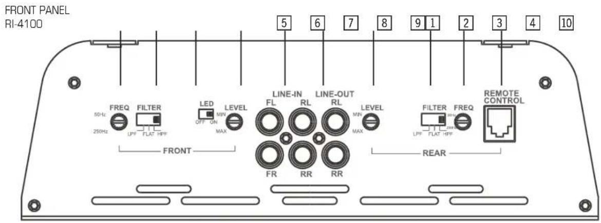
RI-4100
- Crossover frequency control, to adjust the cut-off frequency of the channels CH1/2
- Operation mode selector, slide switch to select Low-pass, Fullrange or Highpass operation of the active crossover for channels CH1/2
- Amplifier Illumination LEDs, switch to turn on or off
- Input gain control, LEVEL adjustment for channels CH1/2. Use to match the RCA line output voltage of the head-unit to the amplifier input section.
- RCA inputs Front and Rear (left and right channels) line inputs for connection with RCA line-out's of the head-unit
- RCA Outputs (left and right channels), line outputs for connection with RCA line-in's of another amplifier
- Input gain control, LEVEL adjustment for channels CH3/4. Use to match the RCA line output voltage of the head-unit to the amplifier input section.
-
Operation mode selector, slide switch to select Lowpass, Fullrange or Highpass operation of the active crossover for channels CH3/4
-
Crossover frequency control, to adjust the cut-in frequency of the channels CH3/4
- "REMOTE" input port for connection with dash-mounted low-pass level remote unit for Rear channels
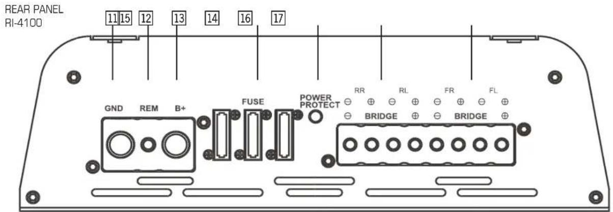
- "GND" for connection to chassis ground or negative terminal of car battery
- "REM" for the automatic (remote) turn-on / turn-off of the power amplifier from the head-unit's remote or antenna control lead
- "B+" for connection to the positive terminal of car battery
- Status LED, is lit blue when power is on and is lit red when the amplifier is shut down because of malfunction, overheating or short-cut on speaker cable leads
- Terminal block for the rear speakers
- Terminal block for the front speakers
14. Fuses
23
2. INPUTS · OUTPUTS · CONTROLS
RI-2135
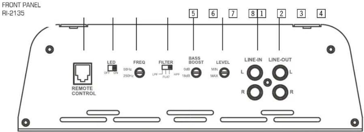
- "REMOTE" input port for connection with dash-mounted low-pass level remote unit
- Amplifier Illumination LEDs, switch to turn on or off
- Crossover frequency control, to adjust the cut-in frequency of the channels CH1/2
- Operation mode selector, slide switch to select Lowpass, Fullrange or Highpass operation of the active crossover for channels CH1/2
- Bass boost control, LEVEL adjustment for the bass boost to get more bass. ATTENTION: Do not increase the level to high. Damage to the speaker would result!
- Input gain control, LEVEL adjustment for channels CH1/2. Use to match the RCA line output voltage of the head-unit to the amplifier input section.
- RCA inputs (left and right channels), line inputs for connection with RCA line-out's of the head-unit
- RCA Outputs (left and right channels), line outputs for connection with RCA line-in's of another amplifier
-
"GND" for connection to chassis ground or negative terminal of car battery
-
"REM" for the automatic (remote) turn-on / turn-off of the power amplifier from the head-unit's remote or antenna control lead
- "B+" for connection to the positive terminal of car battery
- Status LED, is lit blue when power is on and is lit red when the amplifier is shut down because of malfunction, overheating or short-cut on speaker cable leads
- Terminal block for the speakers or subwoofer
12. Fuses
2. INPUTS · OUTPUTS · CONTROLS
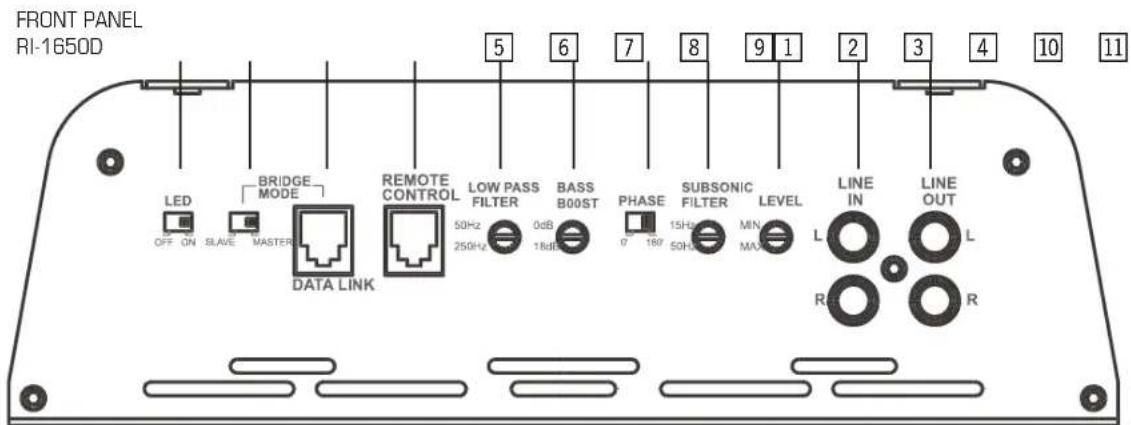
RI-1650D
- Amplifier Illumination LEDs, switch to turn on or off
- Master / Slave, use to link two amplifiers. Set the switch of first amplifier to the "Master"-position and the switch of the second amplifier to the "Slave"-position
- Data Link Port, use two connect two amplifiers via Master / Slave mode
- "REMOTE" input port for connection with dash-mounted low-pass level remote unit
- Lowpass crossover frequency control, to adjust the cut-off frequency
- Bass boost control, LEVEL adjustment for the bass boost to get more bass. ATTENTION: Do not increase the level to high. Damage to the subwoofer can result!
- Slide switch to choose the phase between 0° or 180°
- Subsonic crossover frequency control, to adjust the cut-in frequency of the subwoofer
-
Input gain control, LEVEL adjustment. Use to match the RCA line output voltage of the head-unit to the amplifier input section.
-
RCA inputs (left and right channels), line inputs for connection with RCA line-out's of the head-unit
- RCA Outputs (left and right channels), line outputs for connection with RCA line-in's of another amplifier
- "GND" for connection to chassis ground or negative terminal of car battery
- "REM" for the automatic (remote) turn-on / turn-off of the power amplifier from the head-unit's remote or antenna control lead
- "B+" for connection to the positive terminal of car battery
- Status LED, is lit blue when power is on and is lit red when the amplifier is shut down because of malfunction, overheating or short-cut on speaker cable leads
- Terminal block for the speakers or subwoofer



- INPUTS · OUTPUTS · CONTROLS
text_image
FRONT PANEL RI-4100 5 6 7 8 9 1 2 3 4 10 FREQ FILTER 50Hz FL Filter 250Hz LPF FLAT HFF LED LEVEL LINE-IN LINE-OUT LEVEL FILTER FREQ REMOTE CONTROL OFF ON MAX FL RL RL MIN MAX LPF FLAT HFF REAR
text_image
REAR PANEL RI-4100 11 15 12 13 14 16 17 GND REM B+ FUSE POWER PROTECT RR RL FR FL BRIDGE BRIDGE26

- INPUTS · OUTPUTS · CONTROLS
text_image
FRONT PANEL RI-2135 5 6 7 8 1 2 3 4 LED FREQ FILTER BASS LEVEL LINE-IN LINE-OUT OFF ON 50Hz 250Hz LPF FLAT HPF 0dB 18dB MIN MAX L L REMOTE CONTROL R R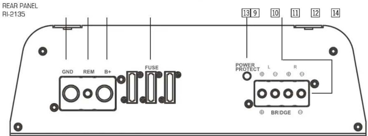
text_image
REAR PANEL RI-2135 GND REM B+ FUSE POWER PROTECT L R BRIDGE27




- INPUTS - OUTPUTS - CONTROLS
text_image
FRONT PANEL RI-1650D LED OFF ON SLAVE MASTER BRIDGE MODE DATA LINK REMOTE CONTROL LOW PASS FILTER 50Hz 250Hz 0dB 1RdB BASS B00ST PHASE 0° 180° 15Hz 50Hz SUBSONIC FILTER LEVEL MIN M/M LINE IN L R LINE OUT L R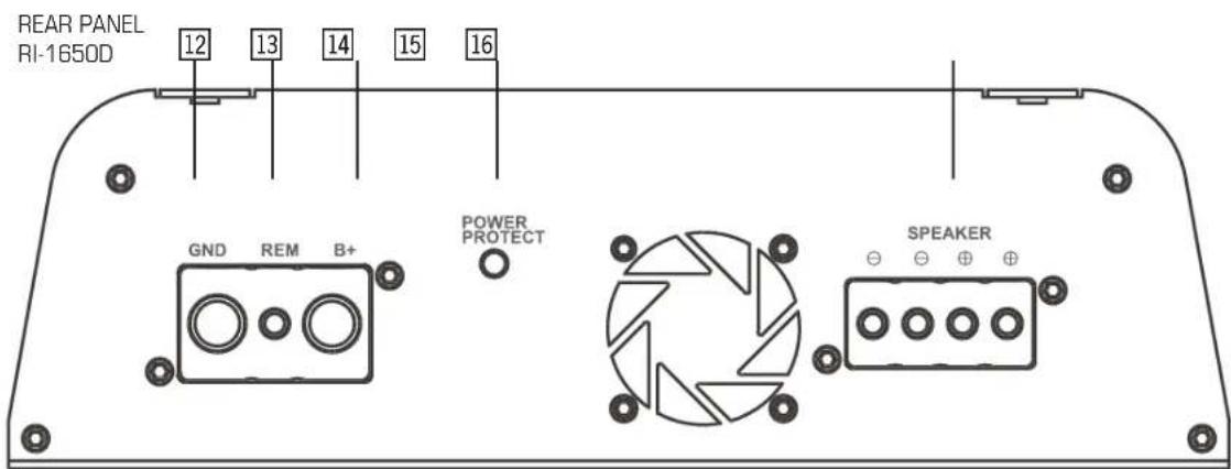
text_image
REAR PANEL RI-1650D 12 13 14 15 16 GND REM B+ POWER PROTECT SPEAKER28

3. mOUNTING Of THE Amplifier
3.1 MOUNTING LOCATION
The mounting location should be carefully selected, preferably in the trunk compartment of your car! In the interest of passive driver and passenger safety, the amplifier must be securely mounted, and special precautions must be taken to allow sufficient cooling. The amp can get quite hot during operation, so a clearance of at least 10cm from both sides and from the top of the amp must be considered.
Make sure there is no wiring harness, fuel tank etc. behind or below the mounting surface that may be damaged by the drilling of the holes for the amplifier mounting screws. The above mentioned clearance of at least cm to all sides of the amplifier is not only for proper cooling, but also because the crossover controls must remain accessible.
The amplifier must NOT be mounted directly to the chassis ground of the vehicle, this may cause to ground loops with loud hum noise.
3.2 MINIMUM IMPEDANCE LOAD
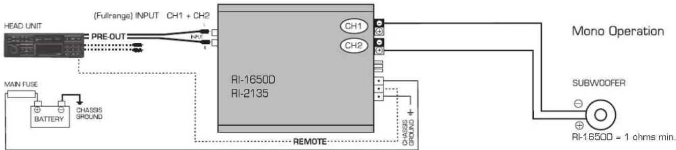
The output stages of the RODEK amplifiers are designed to give you extraordinary output power into 4 and 2 ohms loads in normal stereo configurations. In bridged mode, the minimum impedance load is 4 ohms. The amplifier might suffer from thermal shut-down or even damage, if these recommended minimum impedance load ratings are not considered appropriately. The RI-1650D can drive subwoofers down to 1 ohm impedance.
4. ELECTRICAL wIRING
4. ELECTRICAL WIRING
IMPORTANT! Disconnect the negative battery terminal (GND) or remove the main fuse near the car battery before you start any wiring work!
The power supply of the car audio system must be disconnected until the entire wiring installation is completed.
Use rubber grommets when running cables through any metal or sharp plastic panels, to prevent accidental shorting or shearing. Make sure the cables do not interfere with normal operation of the vehicle.
Especially the music signal cables (RCA interconnects) should be kept far away from any potential sources of electrical interference i.e. electronic vehicle management systems (engine computers, relays etc.) fuel pumps, wiring harnesses etc.!
4.1 RCA INTERCONNECTS / REMOTE LEAD
Carefully run the RCA audio signal interconnect(s) and the remote switching cable from the head-unit to the amplifier.
The audio signal cables should be routed completely separate from the power cables. Use only double or triple shielded quality cables!
Connect the remote wire lead to the remote output of the head-unit and to the remote input terminal of the amplifier. Finally connect the RCA interconnect cable(s) to the respective outputs on the head-unit and the RCA inputs of the amplifier.
4.2 LOUDSPEAKER CABLES
Connect the loudspeaker wires to the speaker terminals of the amplifier. Use good quality wires of 2.5mm ^2 cross-section. When baring wires, remove approximately 6-8mm of the insulation and after axially twisting the wires; insert the bare ends into the corresponding speaker terminal output on the amplifier. Be sure to follow correct polarity (+" to +"; "-" to "-"). Tighten the terminal screws on the amplifier. Also route the bass level remote cable, where applicable.
4.3 CONNECTION OF POWER CABLES
Run the positive power cable ("+12 V") directly from the positive terminal of the car battery to the amplifier. Make sure the power cable makes good contact to the battery; i.e. use an appropriate battery clamp that accepts big gauge power cables! For protection of your car audio system and your entire car against electrical fire hazards from a shortcircuit of the main power cable with chassis ground, you must insert a main fuse (holder) within the first 30cm of the battery. The fuse type/value should be matching the limitations of your main power cable and the requirements of your car audio system. For example 80 A fuse when using the 35 mm ^2 power cable.
Now you route the ground cable to the amplifier. It is best to keep the ground cable ("-12V") as short as possible, i.e. to find a chassis contact very close to the amplifier. The ground power cable must have the same cross section as the positive power cable. It is recommended to use a corrosion-resistant gold-plated power ring or a massive ground clamp between the ground cable and the chassis ground point. Keep in mind that audible interferences and problems originating in the power supply of the amplifier are mostly based on a bad ground contact.
5. CROSSOVER SETTINGS
The RODEK amplifiers feature an active crossover section with full versatility and thus, offer different amplification modes, which can be set by the operation mode slide switch(es). The operation mode switch enables you to configure each stereo channel pair to work in either Fullrange, Highpass or even Low-pass mode. Therefore - before you get started with the settings of crossover frequencies and input gain adjustments - you must select the appropriate operation mode for each channel pair, depending on the speaker system that is connected and driven by the amplifier. This will make sure that every speaker system is only working in its proper frequency operation range, for which the speaker was designed. For example select HIGHPASS, if the speaker is a component- or coaxial type, or LOWPASS in case of a subwoofer system - and finally FULLRANGE if the pass band frequency of the stereo channel is already controlled by a head-unit with an integrated DSP based active crossover.



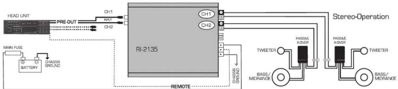
5.2 SYSTEM-CONFIGURATIONS
System-Configuration RI-1650D / RI-2135
flowchart
graph TD
    A["HEAD UNIT"] -->|PRE-OUT| B["RI-2135"]
    B --> C["CH1"]
    B --> D["CH2"]
    C --> E["INPUT"]
    D --> F["CH1"]
    D --> G["CH2"]
    H["MAIN FUSE"] --> I["BATTERY"]
    I --> J["CHASSIS GROUND"]
    J --> K["REMOTE"]
    L["Stereo-Operation"] --> M["TWEETER"]
    M --> N["PASSME X-OVER"]
    N --> O["PASSME X-OVER"]
    O --> P["TWEETER"]
    P --> Q["BASS/MIDRANGE"]
    Q --> R["BASS/MIDRANGE"]
OPERATION MODE SELECTOR CH1/2 set to HPF


flowchart
graph TD
    A["HEAD UNIT"] -->|PRE-OUT| B["RI-1650D"]
    B --> C["CH1 + CH2"]
    B --> D["CH2"]
    E["BATTERY"] --> F["CHASSIS GROUND"]
    F --> G["REMOTE"]
    H["SUBW00FER"] --> I["RI-1650D = 1 ohms min."]
    J["Mono Operation"] --> K["CH1"]
    J --> L["CH2"]
OPERATION MODE SELECTOR CH1/2 set to LPF
32




5.2 SYSTEM-CONFIGURATIONS
System-Configuration RI-4100
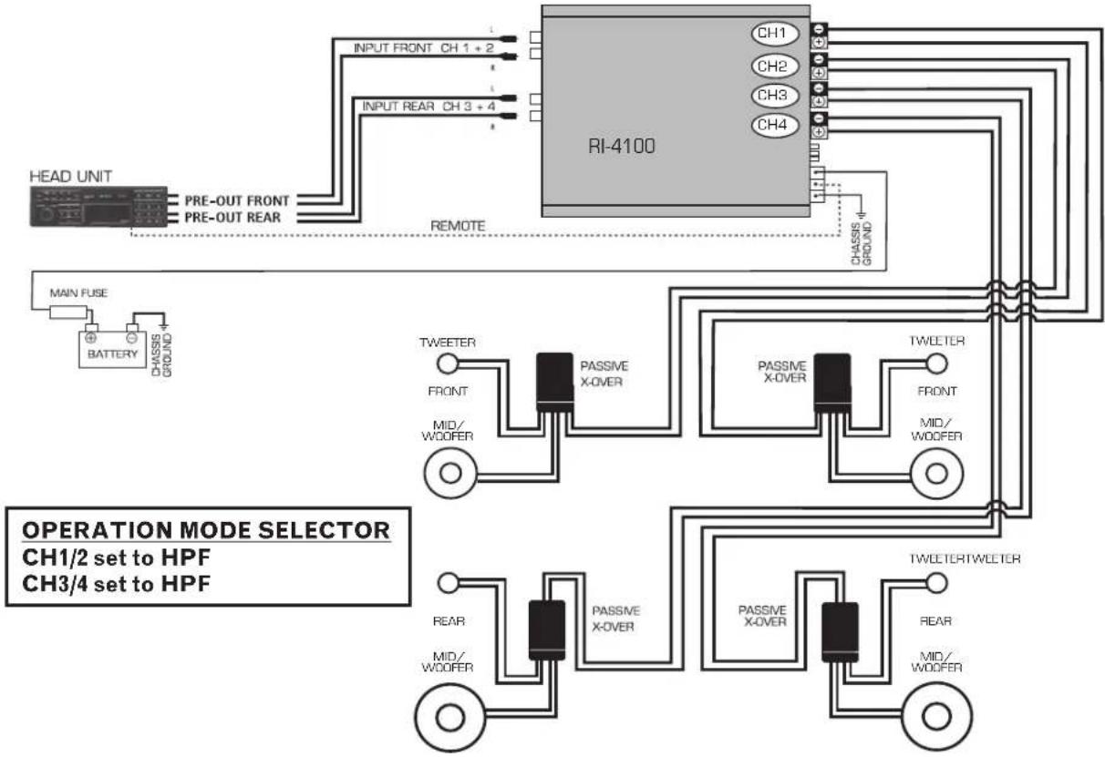
flowchart
graph TD
    A["HEAD UNIT"] --> B["RI-4100"]
    B --> C["MAIN FUSE"]
    C --> D["BATTERY"]
    D --> E["CHASSIS GROUND"]
    B --> F["TWEETER"]
    F --> G["FRONT"]
    G --> H["MID/WOOFER"]
    H --> I["PASSIVE X-OVER"]
    I --> J["TWEETER"]
    J --> K["FRONT"]
    K --> L["MID/WOOFER"]
    L --> M["PASSIVE X-OVER"]
    M --> N["TWEETER/TWEETER"]
    B --> O["REAR"]
    O --> P["MID/WOOFER"]
    P --> Q["PASSIVE X-OVER"]
    Q --> R["TWEETER"]
    R --> S["REAR"]
    S --> T["MID/WOOFER"]
    T --> U["PASSIVE X-OVER"]
    U --> V["TWEETER/TWEETER"]
    style A fill:#f9f,stroke:#333
    style B fill:#ccf,stroke:#333
    style C fill:#cfc,stroke:#333
    style D fill:#fcc,stroke:#333
    style E fill:#cff,stroke:#333
    style F fill:#ffc,stroke:#333
    style G fill:#cfc,stroke:#333
    style H fill:#fcc,stroke:#333
    style I fill:#ffc,stroke:#333
    style J fill:#cfc,stroke:#333
    style K fill:#fcc,stroke:#333
    style L fill:#cfc,stroke:#333
    style M fill:#cfc,stroke:#333
    style N fill:#cfc,stroke:#333
    style O fill:#fcc,stroke:#333
    style P fill:#cfc,stroke:#333
    style Q fill:#cfc,stroke:#333
    style R fill:#cfc,stroke:#333
    style S fill:#cfc,stroke:#333
    style T fill:#cfc,stroke:#333
    style U fill:#cfc,stroke:#333
33




5.2 SYSTEM-CONFIGURATIONS
System-Configuration RI-4100
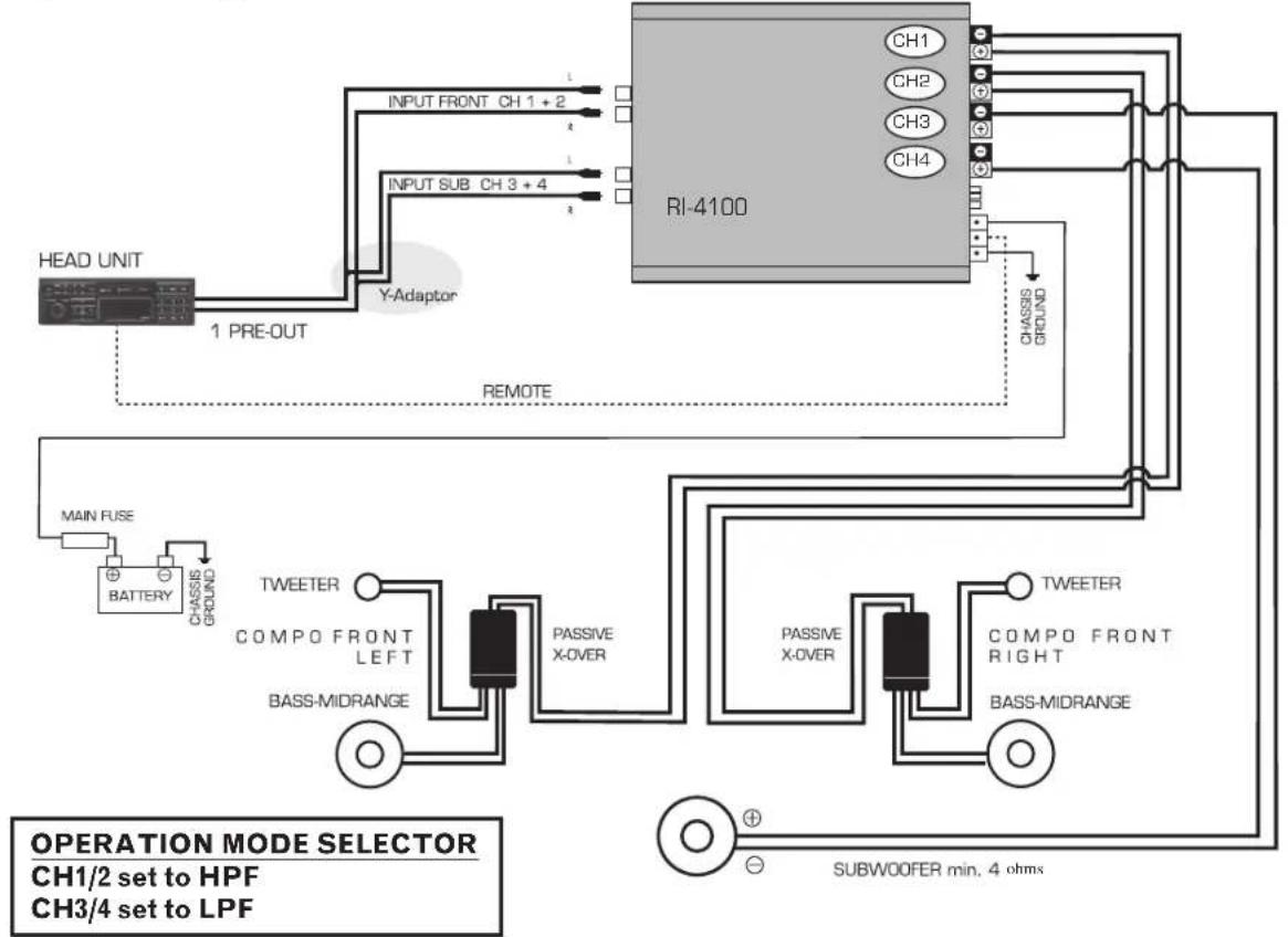
flowchart
graph TD
    A["HEAD UNIT"] -->|1 PRE-OUT| B["Y-Adaptor"]
    B --> C["RI-4100"]
    C --> D["CH1 CH2 CH3 CH4"]
    C --> E["CHASSIS GROUND"]
    F["BATTERY"] --> G["CHASSIS GROUND"]
    H["TWEETER COMPO FRONT LEFT"] --> I["PASSIVE X-OVER"]
    J["BASS-MIDRANGE"] --> K["PASSIVE X-OVER"]
    L["TWEETER COMPO FRONT RIGHT"] --> M["PASSIVE X-OVER"]
    N["BASS-MIDRANGE"] --> O["PASSIVE X-OVER"]
    P["MAIN FUSE"] --> Q["BATTERY CHASSIS GROUND"]
    R["SUBWOOFER min, 4 ohms"] --> S["OPATION MODE SELECTOR CH1/2 set to HPF CH3/4 set to LPF"]
34

CROSSOVER SETTINGS
5.3 HIGHPASS FOR COMPONENT AND COAXIAL SPEAKERS
Before you start your adjustments, all tone controls (i.e. Bass, Treble), fader/balance and the loudness function featured on the head unit, must be set to their respective neutral or centre position.
Please take a look at the chart below, stating the recommended high-pass cross-over frequency settings for coaxial- and component speaker systems - and adjust the Highpass control of each channel pair that drives satellites speaker systems accordingly. The most important factor for the individual adjustment of the Highpass cross-over frequency is the reproduction of mid-bass frequencies and the resulting power-handling of the speaker system. This setting is always a compromise. Try to find a Highpass crossover frequency point that will suit your personal listening preferences and - at the same time - also considers the physical (cone excursion) capabilities of your speaker's best.
Satellite speaker system, front door mounted, recommended highpass frequency
10 cm Coaxial- or Component System 120 - 200 Hz
13 cm Coaxial- or Component System 80 - 120 Hz
16 cm Coaxial- or Component System 60 - 90 Hz
Satellite speaker system, rear mounted, recommended highpass frequency
10 cm Coaxial- or Component System 150 - 200 Hz
13 cm Coaxial- or Component System 120 - 150 Hz
16 cm Coaxial- or Component System 80 - 120 Hz



CROSSOVER SETTINGS
5.4 LOWPASS FOR SUBWOOFER SYSTEMS
To drive a subwoofer system, the integrated electronic crossover must also operate in Lowpass mode. Before you attempt to adjust the Lowpass crossover frequency, you must first turn the (subsonic) Highpass frequency control (only Ri-1650D) counter clockwise to its lowest position at 10 Hz.
Now you can set an appropriate Lowpass crossover frequency. For this purpose, open the input gain control – the arrow of the knob should point to "noon" – so you can hear the subwoofer playing. Ideally, the low-pass cut-off frequency should be set between 50 to 90 Hz – and this setting has to be entirely determined by ear. Try to find Lowpass crossover frequency setting that gives you a "full-bodied" bass reproduction with enough impact in the upper bass range.
Note: If the Lowpass crossover frequency is set too low, the sound will have a tendency to sound extremely soft and low-end heavy!
For RI-1650D: Adjust the Subsonic-Highpass, if you wish to squeeze out the most (max-dB) of your subwoofer system. Turn the Highpass frequency control up, to a point where you can hear that the bass reproduction starts to get "thinner". The subsonic Highpass frequency should be set to a value between 20 to maximum 50 Hz.
5.5 ADJUSTING INPUT SENSITIVITY
To reach a maximum noise-free dynamic headroom from each individual head unit/amplifier/speaker combination, it is important to set the respective input gain controls correctly. The input level settings determine the actual signal-to-noise ratio, and they are also responsible for obtaining the maximum distortion-free SPL (sound pressure level) from your specific setup.
Turn-on your head-unit and set the volume control to approximately 3/4 of full volume, while playing a dynamic track from a CD. Slowly increase the LEVEL adjustment control of the channel pair, to which your subwoofer system is connected to. Turn up the (sub channel) level control knob until you can just about hear distorted bass sounds. Now you reduce the volume level of your head unit to a "normal" listening level and "add" all the remaining channel pairs, by turning up the corresponding level controls - aiming for a balanced sound with a slight emphasis in the bass range. All remaining channels, no matter if this concerns rear mounted coaxial or component systems installed in the front doors, must be balanced against the main level setting of your subwoofer.

CROSSOVER SETTINGS
5.6 ADJUSTMENT OF PHASE SWITCH
The phase switch function of your RODEK amplifier can be activated with the corresponding switch. The phase-shift control enables you to match the acoustical phase relations of subwoofer and the speaker system playing in the front doors, either a component or a coaxial system. The target is that both speaker systems, normally separated by aprox. 3m of distance are intended to play acoustically "in-phase" at the driver's seat location. A good match of the acoustical phase between subwoofer and the system in the front doors will give you the impression of bass sounds coming from a place in front of you. Or the other way round, the subwoofer playing in the trunk of your car can not be localized that easily.
The second advantage is, that the upper bass region - i.e. where the sound waves radiated by the subwoofer and the kickbass or front door mounted component system is crossing over - will sound considerably more precise and tight. This phase adjustment can only be determined by ear, there is no rule of thumb to find a good match, and you will definitely need somebody to help you. To judge the effect of the phase-shift adjustment, you must sit in the driver's seat, and somebody must adjust the phase shift control switch until the sound reproduction in the bass region is best. Furthermore, it might be necessary to invert the (connection) polarity of your subwoofer - and re-adjust the phase. if you can not find a proper match with the correct in-phase polarity subwoofer connection.



- TECHNICAL SPECIFICATIONS
| RI-4100 RI-2135 RI-1650D | |||
| Rated Power OutputAll channels driven simultaneously@ 13.8 V into 4 Ohms (THD<1%) | 4x85W 2x125W 1x520W | ||
| Rated Power OutputAll channels driven simultaneously@ 13.8 V into 2 Ohms (THD<1%) | 4x140W 2x200W 1x910W | ||
| Rated Power OutputAll channels driven simultaneously@ 13.8 V into 4 Ohms (THD<1%) Bridged | 2x250W 1x400W n/a | ||
| Damping Factor @ 4 Ohms Load All Channels > 75 > 75 > 200 | |||
| Signal-to-Noise Ratio (A-Filter Weighted)All Channels @ full rated power output | > 88dB > 88dB > 70dB | ||
| Frequency Response (-3dB)Operation Mode set to FULL,All Channels driven simultaneously | 10Hz - 40kHz 10Hz - 40kHz 10Hz - 400Hz | ||
| Channel SeparationAll Channels | > 50dB > 50dB n/a | ||
| Input SensitivityAll channel Pairs | 0.2V - 8V 0.2V - 8V 0.2V - 8V | ||
| Integrated Cross-Over/FilteringSlope Rates | 12 dB/Octave High- & Lowpass | ||
| Highpass Cross-Over Frequency RangeLowpass Cross-Over Frequency Range | continuously variable 50 - 250 Hzcontinuously variable 50 - 250 Hz | 10 - 50 Hz40 - 400 Hz | |
| Fuses 3 x 25 A 3 x 25 A | 4 x 30 A | ||
| Dimensions (W x H x D) | 431 x 81 x 298 mm | 431 x 81 x 298 mm | 581 x 81 x 298 mm |
7. WARRANTY
Thank you for purchasing this RODEK amplifier. It is advisable to keep the original packing material for future transporting of the product. Please read the warranty specifications below carefully.
Should your RODEK product require warranty service, please return it to the retailer from whom it was purchased, or the distributor in your country. Please do not send any product to RODEK Inc. U.S.A. Should you have difficulty in finding an authorized RODEK service center, details are available from your local distributor.
This RODEK amplifier is fully warranted against defective materials or workmanship for a period of TWO YEARS from date of purchase at retail. Warranty work will not be carried out unless this warranty certificate is presented fully completed with model, serial number, purchaser's address, purchasing date and dealer stamp together with the original sales slip!
WARRANTY LIMITATIONS
This warranty does not cover any damage due to:
- Improper installation, incorrect audio or mains connection(s).
- Exposure to excessive humidity, fluids, sun rays or excessive dirt or dust.
- Accidents or abuse
- Unauthorized repair attempts and modifications not explicitly authorized by the manufacturer.
This warranty is limited to the repair or the replacement of the defective product at the manufacturer's option and does not include any other form of damage, whether incidental, consequential or otherwise. The warranty does not cover any transport costs or damages caused by transport or shipment of the product.
Date of purchase: ....
Your name:
Your address:
City:
State: ZIP or postal code:
Country:
Your phone number: ____
Dealer's address & stamp
RoDEK
Exclusive distributor for Europe and Asia