Multizone - Receiver Audica - Free user manual and instructions
Find the device manual for free Multizone Audica in PDF.


User questions about Multizone Audica
0 question about this device. Answer the ones you know or ask your own.
Ask a new question about this device
Download the instructions for your Receiver in PDF format for free! Find your manual Multizone - Audica and take your electronic device back in hand. On this page are published all the documents necessary for the use of your device. Multizone by Audica.
USER MANUAL Multizone Audica
Installation Manual for:
multizone
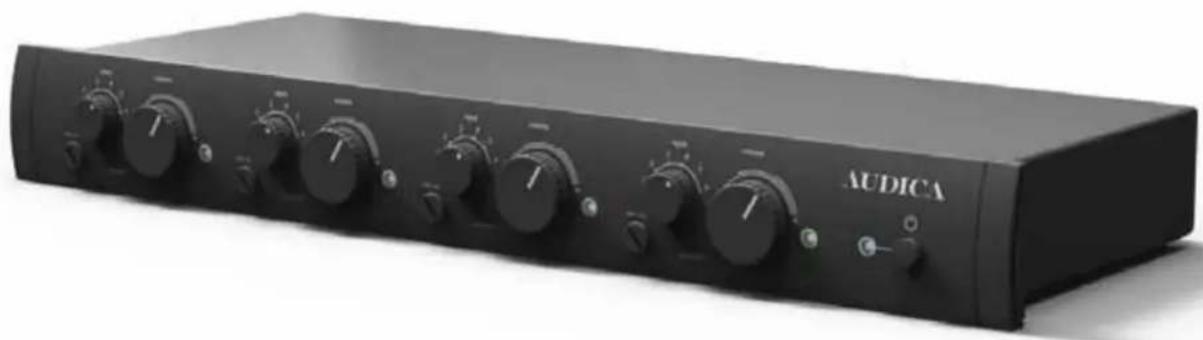
4 zone controller
natural_image
Black audio amplifier device labeled 'AUDICA' with multiple knobs and control buttons (no visible text beyond brand name)Contents
| Overall | Description | 3 | |||
| Technical | specification | 3 | |||
| Front | Panel | Controls | 4 | ||
| Rear Panel Connectors and Controls | 4 | ||||
| Appendix 1 | Microphone compressor and ducker operation | 8 | |||
| Appendix 2 | Remote Zone Controller connections | 8 | |||
| Appendix 3 | LOOP input and output connections | 8 | |||
| Appendix | 4 | RS-232 | Interface | 9 | |
| Appendix 5 | Operation with Audica Speaker Eq and Subwoofer | 12 | |||
ATTENTION!
RISQUE DE CHOC ELECTRIQUE NE PAS OUVRIR

POUR REDUIRE LE RISQUE DE CHOC ELECTRIQUE, NE PAS DEPOSER LE BOITIER (NI LE PANNEAU ARRIERE) AUCUNE PIECE INTERNE NE PEUT ETRE DEPOSEE PAR L'UTILISATEUR CONSULTER UN PROFESSIONEL QUALIFIE POUR TOUTE REPARATION
Read these instructions.
Keep these instructions.
Heed all warnings.
Follow all instructions.
1. PRECAUTIONS
WARNING - To reduce the risk of electric shock do not remove any panels or covers. There are no user serviceable parts in this product.
WARNING - To reduce the risk of fire or electric shock, do not expose this apparatus to rain or moisture.
READ ALL INSTRUCTIONS before attempting to install or use the product.
RETAIN INSTRUCTIONS for future reference.
WATER AND MOISTURE – Do not use this product near water, for example sinks, bath tubs, wet areas and the like. The product shall not be exposed to dripping or splashing and no objects filled with liquids, such as vases, shall be placed on the product.
OBJECT OR LIQUID ENTRY - Do not insert any object or liquid into the openings in the product as this may cause electric shock or malfunction.
HEAT – Do not install the product near any heat sources such as radiators, heat registers, stoves or other apparatus (including amplifiers) that produce heat.
CLEANING – Clean only with a dry cloth.
MOVING/TRANSPORTING THE PRODUCT – The product should be packed in its original packaging for moving from location to location.
OVERLOADING - Never overload mains outlets, extension cables or multi-way plug extensions as this may cause fire or electric shock.
POWER CORD – Do not defeat the safety purpose of the grounding-type plug. The plug has two blades and a third grounding prong. The third prong is provided for your safety. If the provided plug does not fit your outlet, consult and electrician for replacement of the obsolete outlet.

POWER CORD PROTECTION – Protect the power cord from being walked on or pinched, particularly at plugs, convenience receptacles, and the point where it exits from the apparatus.
ACCESSORIES - Use only attachments/accessories specified by the manufacturer.
CARTS/STANDS – Use only with the cart, stand, tripod, bracket or table specified by the manufacturer or sold with the apparatus. When a cart is used, use caution when moving the cart/apparatus combination to avoid injury from tip-over.
LIGHTNING – Unplug this apparatus during lightning storms or when unused for long periods of time.
2. SERVICING
Refer all servicing to qualified personnel. Servicing is required when the apparatus has been damaged in any way, such as power-supply cord or plug is damaged, liquid has been spilled, or objects have fallen into the apparatus, the apparatus has been exposed to rain or moisture, does not operate normally, or has been dropped.
Do not attempt to service this product yourself as opening covers or panels may expose you to dangerous voltages or other hazards.
Where replacement parts are required be sure the service technician has used replacements supplied by the manufacturer or have the same characteristics as the original part. Use of unsuitable parts could cause fire, electric shock or other hazards and may void any warranty or guarantee.
The technician must perform any safety checks to test the performance of the product upon completion of any repairs.
Overall Description:
The Audica Professional MULTIzone is a zone control mixer with 4 zone outputs and 6 music inputs plus a microphone input for paging applications. Each of the 4 zone outputs can be independently configured to provide music from one of the inputs plus the paging microphone, with the relative levels set by front panel controls. When the microphone is used, the music is automatically reduced in level ("ducking") to allow for announcements to be heard clearly. Each zone output is mono but all inputs are stereo capable (mixed to mono internally).
Zone outputs can have Audica speaker EQ applied if needed. A mute control input is provided to be linked to fire control systems. This mutes all music inputs whilst keeping the paging microphone active for safety announcements.
Remote zone control is possible via wired wall-mount control panels or an RS-232 interface.
text_image
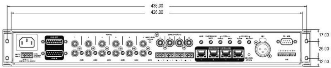
438.00 426.00 17.00 25.00 12.00
text_image
450.00 AUDICA multizone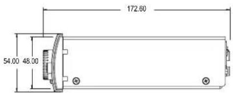
text_image
172.60 54.00 48.00Technical specification
Inputs
Line inputs Input impedance 10kΩ at maximum gain – increases as gain is reduced
Input voltage range for full scale 240mV (maximum gain) - 6.4V (minimum gain)
Microphone input Input impedance 10kΩ balanced
Input voltage range for full scale 4mV (maximum gain) - 3.3V (minimum gain)
Outputs
| Zone outputs - Line Output impedance 200Ω | |||||
| Maximum | output | level | 1.8 | Vrms | |
| Zone outputs - Balanced Output impedance 400Ω | |||||
| Maximum | output | level | 3.6 | Vrms | |
Front Panel Controls
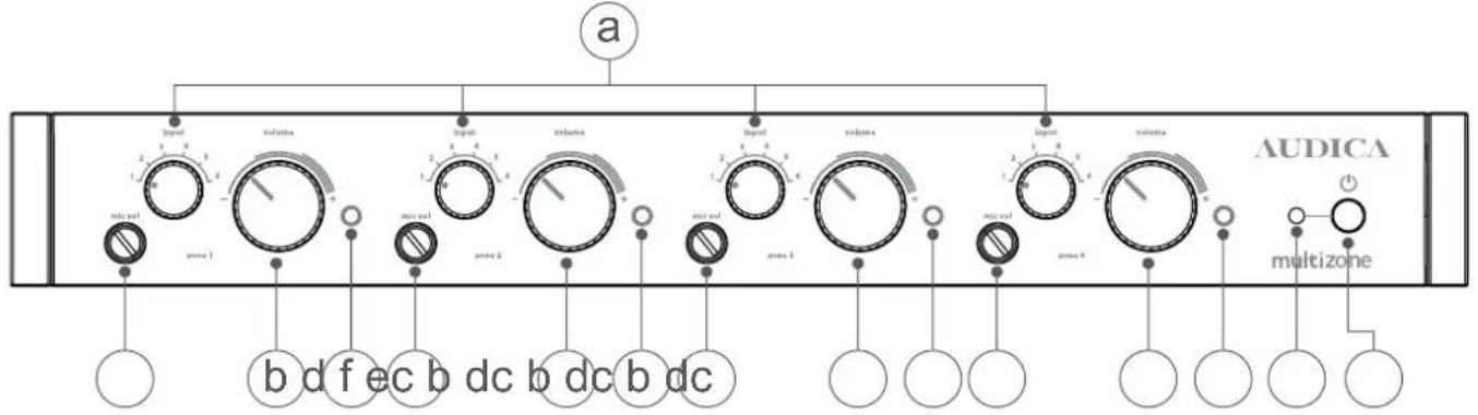
text_image
a AUDICA multizone input volume input volume input volume input volume b d f e c b d c b d c multizonea) Input Select
Choose one line input channel (1 to 6) to send to each zone output (1 to 4).
b) Zone Volume
Set the volume level for each zone (1 to 4). Turn clockwise to increase volume, anticlockwise to decrease.
c) Mic Volume
Four screwdriver controls set the volume level from the paging microphone mixed with each zone's music signal (zones 1 to 4). When set to zero, music ducking (see Appendix 1) is disabled for that zone.
d) Zone signal indicator
This white indicator LED illuminates when a signal is present. The brightness of the LED gives some indication of the signal level.
e) Power On/Off
This is a true mechanical power switch (not a standby mode). Its position is retained even during mains power failure.
f) Power on indicator
This blue indicator LED is off when the power switch is off and lights blue when the mains power is on. Rapid flashing indicates that the RS-232 enabled standby mode is in operation.
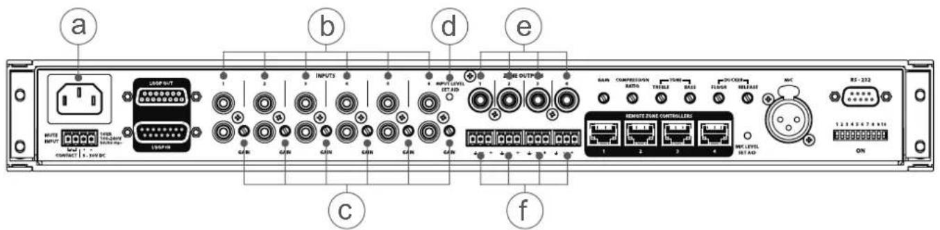
Rear Panel Connectors and Controls
text_image
a b c d e F C f INPUTS OUTPUTS GAIN GAIN GAIN GAIN GAIN GAIN GAIN GAIN GAIN GAIN GAIN GAIN GAIN GAIN GAIN GAIN GAIN GAIN GAIN GAIN GAIN GAIN GAIN GAIN GAIN GAIN GAIN GAIN GAIN GAIN GAIN GAIN GAIN GAINa) Mains power input
IEC 3-pin connector. Use power cord supplied.
WARNING – The power cord must be connected to a power socket outlet with a protective earth connection.
b) Line Inputs
Six line input channels on RCA phono pairs, each of which can accept a mono or stereo source (stereo sources are internally mixed down to mono). The front panel Input Select switches (see above) pick which channel is to be sent to each Zone output.
c) Line input gain controls
Rotary potentiometer to set gain for input channels 1, 2, 3, 4, 5 and 6.
d) Input level set aid
A single 2-colour LED is provided to assist setting the line input levels. By applying a signal on each input in turn the level can be set optimally. Green indicates the signal is in the optimum range (> -20dB) and Red indicates that clipping is imminent (> -2dB)
e) Zone Outputs (unbalanced)
Four mono RCA phono sockets carry the Zone (Line) outputs. Each Zone Output can be selected to have a flat frequency response or the Audica speaker EQ (AEQ) equalisation (see page 6).
f) Zone Outputs (balanced)
Balanced audio outputs are provided on 3-way Phoenix connectors for Zones 1, 2, 3 and 4. These replicate RCA jack outputs for each zone. The balanced output level is double the unbalanced output.
If taking a single-ended output from the balanced output terminals then use the ground pin for screen and '+' pin for signal. DO NOT connect the '-' output pin to ground.
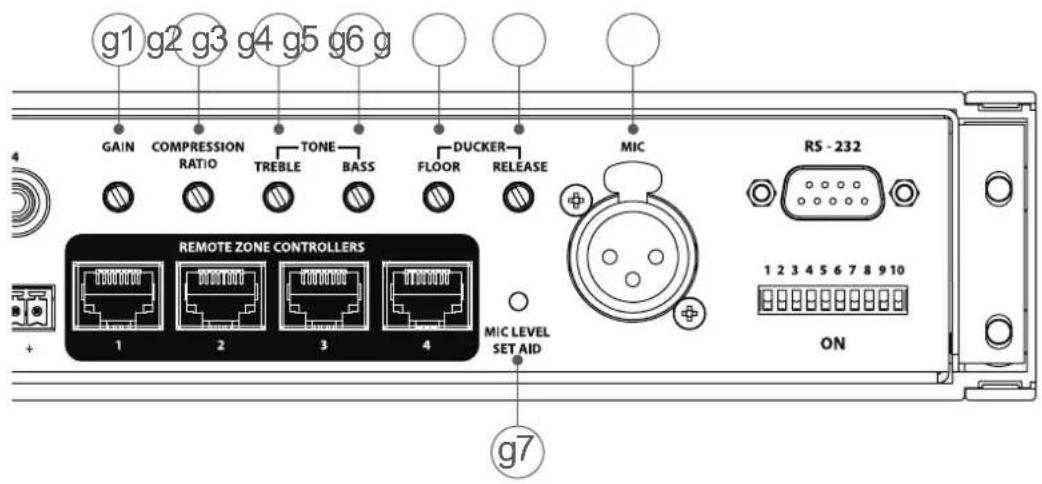
text_image
g1 g2 g3 g4 g5 g6 g GAIN COMPRESSION TONE DUCKER MIC RATIO TREBLE BASS FLOOR RELEASE REMOTE ZONE CONTROLLERS 1 2 3 4 MIC LEVEL SET AID RS - 232 ON 1 2 3 4 5 6 7 8 9 10 g7g) Microphone Input
An XLR balanced input for a paging microphone. A 48V "phantom power" option is provided for active or condenser microphones – selected via the DIL switch (see next page). The microphone signal can be processed in various ways using 6 rotary potentiometers.
g1) GAIN
Rotary potentiometer sets the gain of the microphone input – to accommodate different microphones. Since the gain range on the Mic input is +50dB to -10dB this can also be used as a line level input (maximum input 3.3Vrms).
Rotary potentiometer sets the compressor contribution to microphone channel.
g3) TREBLE
Mid-high tone control on microphone channel (centred at 5kHz).
g4) BASS
Low-mid tone control on microphone channel (centred at 150Hz).
g5) DUCKER - FLOOR
Rotary potentiometer sets the music ducking "floor level" (music attenuation level).
g6) DUCKER – RELEASE
Rotary potentiometer sets the music ducking release time (music fade-up time).
g7) MIC LEVEL SET AID
This is a 2-colour LED to assist in MIC input level setting. Green indicates the signal is in the optimum range (> -20dB) and Red indicates that clipping is imminent (> -2dB
[A more detailed description of the compressor and ducker operation can be found in Appendix 1.
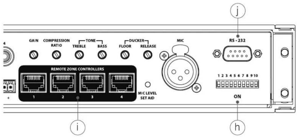
text_image
GAIN COMPRESSION RATIO TREBLE BASS DUCKER RELEASE MIC REMOTE ZONE CONTROLLERS 1 2 3 4 MIC LEVEL SET AID i j R5 - 232 1 2 3 4 5 6 7 8 9 10 ON hh) DIP switch
DIP switches are "ON" when down and "OFF" when up. The default setting is with all switches set OFF (up). The table below describes their effect.
| SW | Function | DIP switch UP | DIP switch DOWN | Notes |
| OFF | ON | |||
| 1 | RS-232 Address LSB 0 | 1 | Use these switches to set the “unit number” for RS-232 addressing. See Appendix 4 for details.Set all three switches to “0” (UP) to lock the unit into Manual mode – disabling all RS-232 control. | |
| 2 | RS-232 Address 0 2 | |||
| 3 | RS-232 Address MSB 0 | 4 | ||
| 4 | RS-232 source – when unit is SLAVE | Unit is controlled from local RS-232 socket | RS-232 control from LOOP input | When unit is master, RS-232 signal is sent to LOOP out – so DIP switch has no effect. |
| 5 | MIC source – when unit is SLAVE | Local microphone “ducks” unit’s Zone outputs | Master (LOOP) microphone “ducks” unit’s Zone outputs | When unit is master, ducking signal is sent to LOOP out – so DIP switch has no effect. ** |
| 6 | Phantom Power | off | on | Phantom power to microphone |
| 7 | Zone 1 Audica EQ | off | AEQ | Audica speaker EQ is designed to optimise performance from Audica Pro loudspeakers.If Audica Speaker EQ is to be used in a system with a subwoofer, please refer to Appendix 5. |
| 8 | Zone 2 Audica EQ off | AEQ | ||
| 9 | Zone 3 Audica EQ | off | AEQ | |
| 10 | Zone 4 Audica EQ | off | AEQ |
**In a system with only a single MULTIzone unit, if DIP switch 5 is set ON then any microphone signal will "duck" the music signal in whichever zone(s) the microphone level is set above zero – but the microphone signal will not be heard.
i) Remote Zone Controller inputs
Four RJ-45 sockets for connection to remote Zone Control wall plates. Connect via an 8-way CAT-5 cable terminated with RJ-45 plugs at each end for each Zone. The Zone Control wall plate takes over control of Zone input select and volume control – disabling the front panel controls for that zone. See Appendix 2 for further details.
j) RS-232 control input
9-pin male "D-type" connector. See Appendix 4 for further details and the RS-232 control protocol.
text_image
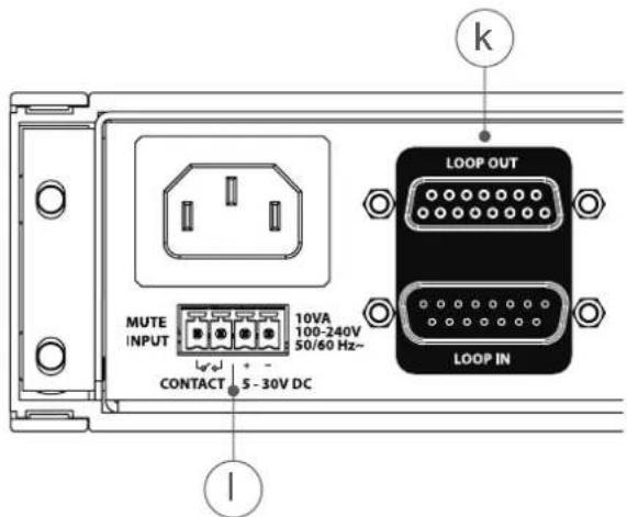
MUTE INPUT 10VA 100-240V 50/60 Hz~ CONTACT 5 - 30V DC LOOP OUT LOOP IN kk) LOOP input and output connectors
These are 15-pin D-type connectors (male for Loop out, female for Loop in) for looping the audio inputs (and optionally Mic, Mute and RS-232) to other units. Up to a total of 7 MULTIzone units can be linked in this way. When a unit has a loop cable connected to its LOOP IN socket it becomes a "Slave". The unit which has nothing plugged into its LOOP IN socket is the Master unit. See Appendix 3 for further details.
I) MUTE input
Some buildings require that the music system is muted if the fire alarm is triggered. Two types of input are provided on the unit for this purpose - on a 4-way Phoenix connector.
The first two pins accept a DC voltage input (5-30V) for muting.
The third and fourth pins may be wired to Normally Open isolated contacts (e.g. a relay activated by the fire control panel).
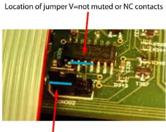
The sense of the Mute input can be reversed by an internal jumper such that a Normally Closed contact or absence of the 5-30V causes muting instead. The internal jumper, plugged into CON302, is located at the front edge of the main PC board, adjacent to the left hand ribbon cable from the front panel – see below
text_image
Location of jumper V=not muted or NC contacts CON302Location of jumper V=mute or NO contacts (default)
Appendix 1
Microphone compressor and ducker operation
A variable compressor effect is provided to help level out differences in loudness caused by different microphone users. This also helps prevent overload of the loudspeakers from any knock or pop noises received by the microphone or the differing mic technique of various users. The "Compression Ratio" control adjusts the balance between compressed and uncompressed mic signal. Fully counterclockwise delivers uncompressed audio, fully clockwise delivers only the compressor output.
The mix of the microphone signal into each zone is controlled by its "preset" rotary control, adjustable via a screwdriver on the front panel. When the microphone signal exceeds a threshold the zone's music level is reduced automatically to a level which allows the microphone signal to be clearly heard. The rear panel "Ducker Floor" control adjusts the degree of music attenuation applied. The "Ducker Release" control adjusts the time delay before the music fades back up again.
Note: The ducker will action will only take effect in zones whose front panel "mic vol" control is set above zero.
Appendix 2
Remote Zone Controller connections
| Pin No. | Connection |
| 1 Ground | |
| 2 | +3.3V |
| 3 | Control |
| 4 Volume (DC voltage) | |
| 5 | Source select (DC voltage) |
| 6 | +3.3V |
| 7 | Ground |
| 8 | +5V |
The "Control" line may be used to disable the remote wall control plate and revert to front panel control. If the "Control" line is shorted to ground via a switch, the zone reverts to front panel control. A red LED back-illuminates the wall plate to indicate that the controls are disabled.
Appendix 3
LOOP input and output connections
| Pin No. | Connection |
| 1 | Ground |
| 2 -6V | LOOP |
| 3 | +6V LOOP |
| 4 | SLAVE_DETECT (grounded by Master Loop-out) |
| 5 | MUTE_LOOP |
| 6 | RS-232_LOOP |
| 7 | DUCKER_LOOP |
| 8 | Ground |
| 9 Master unit input source 1 | |
| 10 | Master unit input source 2 |
| 11 | Master unit input source 3 |
| 12 Master unit input source 4 | |
| 13 | Master unit input source 5 |
| 14 | Master unit input source 6 |
| 15 Mid Signal loop | |
Appendix 4
RS-232 Interface
An RS-232 control interface allows remote control of all basic functions of MULTIzone. The RS-232 interface is uni-directional, MULTIzone does not transmit any data. Commands will be sent as RS-232 serial communication at 9600 baud, 8 bits, no parity bits, 1 stop bit and no flow control. All characters will be sent as ASCII, not delimited and ending with a line feed (0x0A).
Multiple MULTIzone units can either be addressed and controlled from separate RS-232 control sources, or alternatively the user is able to set an address for each MULTIzone unit via its rear panel switches, allowing multiple chained units to be controlled from a single RS-232 control source. If this feature is required, then the user simply sets the RS-232 source to "LOOP" via the rear panel switch (DIP switch #4) and assigns a different address for each MULTIzone unit (DIP switches 1, 2 and 3). RS-232 data is then relayed to each looped unit using the same cable as the signal loop-through.
A DIP switch setting "000" locks the unit into manual panel mode, disabling all RS-232 control for that unit – see page 6.
Note: when using RS-232 control, no more than 7 units can be looped using a single RS-232 controller (i.e. up to 28 zones).
A structure of RS-232 commands is provided that allow operation of MULTIzone at the 'system' level, 'unit' level or 'zone' level. System commands cause every MULTIzone to respond. Unit commands cause only the addressed unit to respond. Zone commands cause only the selected zone on a selected unit to respond.
The RS-232 interface has additional functionality in that it can be used to put MULTIzone in standby. A specific "sbyoff" command will reduce power consumption to <0.5W by shutting down all internal systems. An "sbyon" command will then restore system operation but it is important to note that the unit will take several seconds to fully awake, during which time no audio will be heard and no other RS-232 commands can be received or acted upon. The programming of the RS-232 source device must take this into consideration.
RS-232 connector wiring
| Pin No. | Connection |
| 1 | No connection |
| 2 | RS-232 receive (RX) |
| 3 | No connection |
| 4 | No connection |
| 5 | Ground |
| 6 No connection | |
| 7 | No connection |
| 8 | No connection |
| 9 No connection | |
System command format
| Command Type | RS-232 Command | MULTIzone command response |
| SYSTEM s | 99sbyoff All units | enter standby mode |
| SYSTEMs | 99sbyon All units | power up out of standby |
| SYSTEM s | 99muten All units | all zones enter mute |
| SYSTEMs | 99mutdis All units | all zones de-mute |
| SYSTEM s | 99comen All units | all zones enter RS-232 control mode |
| SYSTEMs | 99comdis All units | all zones enter manual front panel control mode |
Unit command format
| Command Type | RS-232 Command | MULTIzone command response |
| UNIT sXXsbyoff Unit Y enters standby | ||
| UNITsXXsbyon Unit Y powers up from standby | ||
| UNIT sXXmuten Unit Y all zones enter mute | ||
| UNITsXXmutdis Unit Y all zones de-mute | ||
| UNIT sXXcomen Unit Y all zones enter RS-232 control mode | ||
| UNIT | sXXcomdis | Unit Y all zones enter manual front panel control mode |
| Where XX = | Responding unit Y DIP switch address |
| 01 1 | |
| 05 2 | |
| 09 3 | |
| 13 4 | |
| 17 5 | |
| 21 6 | |
| 25 7 |
Zone command format
As a number of MULTIzone units can be looped together the zone command should refer to the absolute zone within the loop. i.e. in a system with three MULTIzone units, zone 2 of unit 3 would be referenced as zone 10.
| Command Type | RS-232 Command Note | DIP switch setting | ||
| Switch 3 | Switch 2 | Switch 1 | ||
| UNIT | s01 | Command only applies to unit1 zone 1 | 0 | 0 |
| UNIT | s02 | Command only applies to unit1 zone 2 | 0 | 0 |
| UNIT | s03 | Command only applies to unit1 zone 3 | 0 | 0 |
| UNIT | s04 | Command only applies to unit1 zone 4 | 0 | 0 |
| UNIT | s05 | Command only applies to unit 2 zone 1 | 0 | 1 |
| UNIT | s06 | Command only applies to unit 2 zone 2 | 0 | 1 |
| UNIT | s07 | Command only applies to unit 2 zone 3 | 0 | 1 |
| UNIT | s08 | Command only applies to unit 2 zone 4 | 0 | 1 |
| UNIT | s09 | Command only applies to unit 3 zone 1 | 0 | 1 |
| UNIT | s10 | Command only applies to unit 3 zone 2 | 0 | 1 |
| UNIT | s11 | Command only applies to unit 3 zone 3 | 0 | 1 |
| UNIT | s12 | Command only applies to unit 3 zone 4 | 0 | 1 |
| UNIT | s13 | Command only applies to unit 4 zone 1 | 1 | 0 |
| UNIT | s14 | Command only applies to unit 4 zone 2 | 1 | 0 |
| UNIT | s15 | Command only applies to unit 4 zone 3 | 1 | 0 |
| UNIT | s16 | Command only applies to unit 4 zone 4 | 1 | 0 |
| UNIT | s17 | Command only applies to unit 5 zone 1 | 1 | 0 |
| UNIT | s18 | Command only applies to unit 5 zone 2 | 1 | 0 |
| UNIT | s19 | Command only applies to unit 5 zone 3 | 1 | 0 |
| UNIT | s20 | Command only applies to unit 5 zone 4 | 1 | 0 |
| UNIT | s21 | Command only applies to unit 6 zone 1 | 1 | 1 |
| UNIT | s22 | Command only applies to unit 6 zone 2 | 1 | 1 |
| UNIT | s23 | Command only applies to unit 6 zone 3 | 1 | 1 |
| UNIT | s24 | Command only applies to unit 6 zone 4 | 1 | 1 |
| UNIT | s25 | Command only applies to unit 7 zone 1 | 1 | 1 |
| UNIT | s26 | Command only applies to unit 7 zone 2 | 1 | 1 |
| UNIT | s27 | Command only applies to unit 7 zone 3 | 1 | 1 |
| UNIT | s28 | Command only applies to unit 7 zone 4 | 1 | 1 |
| Wherecan be | MULTIzone command response | Range of | Notes |
| vol | Sets absolute volume level of zone | 000 to 027 | 000=MIN, 027=MAX |
| vo+ | Increments volume level of zone | N/A | Will not increment above 027 |
| vo- | Decrements volume level of zone | N/A | Will not decrement below 000 |
| muton | Zone enters mute | N/A | Previous volume level recorded |
| mutoff | Zone de-mutes | N/A | Previous volume level restored |
| comon | Zone enters RS-232 control | N/A | Manual panel controls disabled – RS232 settings asserted |
| comoff | Zone exits RS-232 control | N/A | RS-232 mode disabled – manual panel settings asserted |
| src | Selects input source (1 through 6) as zone output | 1 to 6 | Selects source 1 through 6 |
Before a zone can be brought under RS-232 control it must first be switched from manual panel mode to RS232 by using the "comon" for a particular zone, or the "comen" system wide or unit command (all described above).
Note: the front panel controls will be disabled when the unit is in RS-232 mode. Make sure the required unit zones are brought out of RS232 by sending the appropriate "comoff" or "comdis" commands.
Command examples, RS-232 source sends:
$s99sbyoff <line feed> > All units enter standby
$s04comon<line feed> > Turn on RS-232 communications for zone 4
$s05comoff<line feed> > Turn off RS-232 communications for unit 2, zone 1
$s99comen<line feed> > Turn on RS-232 communications for every zone on every unit
$s09comdis<line feed> > Turn off RS-232 communications for every zone on unit 3

$s02src2<line feed> > Sets zone 2 (unit 1 zone 2) to source 2
$s10src3<line feed> > Sets zone 10 (unit 3 zone 2) to source 3
$s08vo+<line feed> > Increments volume on zone 8 (unit 2 zone 4)
$s03vo-<line feed> > Decrements volume on zone 3 (unit 1 zone 3)
$s14vol012<line feed> > Sets absolute volume level of zone 14 (unit 4 zone 2) to level 12
$s99muten<line feed> > Mutes every zone on every unit
When MULTIzone is powered on, the previous status of the unit will be restored. If a particular zone of the unit was previously in RS-232 mode the particular settings for that zone will be restored, e.g. the source input, volume level, or mute. Alternatively, if a particular zone was in manual panel mode the front controls will become active.
Appendix 5
Operation with Audica Speaker Eq and Subwoofer
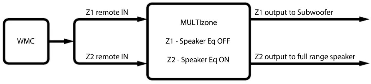
If the MULTIzone is to be used with a speaker system which requires Audica Speaker Eq and also includes a subwoofer, then two zones must be employed. One zone is set to a flat response (Eq off) to drive the subwoofer and one with Eq on to drive the full range speaker. This appendix describes two arrangements which can achieve this end.
1.0 USE 2 ZONES CONTROLLED BY A SINGLE WALL MOUNT CONTROLLER (WMC)
flowchart
graph LR
    A["WMC"] --> B["Z1 remote IN"]
    A --> C["Z2 remote IN"]
    B --> D["MULTlzone"]
    C --> D
    D --> E["Z1 output to Subwoofer"]
    D --> F["Z2 output to full range speaker"]
    G["Z1 - Speaker Eq OFF"] --> D
    H["Z2 - Speaker Eq ON"] --> D
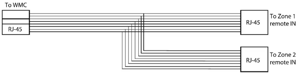
Connect the WMC using a special RJ-45 remote control cable (wired as a simple "Y" – see below) to two remote control inputs on the MULTlzone (in this case Zones 1 and 2). Then set speaker EQ OFF on Zone 1 (DIP switch #7 OFF) to drive the subwoofer and EQ ON on Zone 2 (DIP switch #8 ON) to drive the full-range speaker.
The WMC selects the source fed to both zones and the input gain for that source is set in the normal way. The WMC volume control becomes the "master" volume control for both Zone 1 and Zone 2 outputs.
Advantages: Simple
Disadvantages: Requires WMC and special RJ-45 "Y" cable (below)
flowchart
graph TD
    A["To WMC"] --> B["RJ-45"]
    C["To Zone 1 remote IN"] --> D["RJ-45"]
    E["To Zone 2 remote IN"] --> F["RJ-45"]
    B --> G["Output"]
    F --> H["Output"]
RJ-45 "Y" cable for 2-zone control
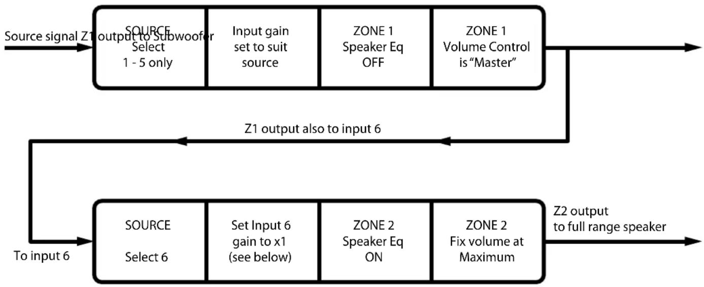
2.0 CASCADE 2 ZONES
flowchart
graph LR
    A["Source signal Z1 output to Subwoofer"] --> B["SOURCE Select 1 - 5 only"]
    B --> C["Input gain set to suit source"]
    C --> D["ZONE 1 Speaker Eq OFF"]
    D --> E["ZONE 1 Volume Control is "Master""]
    E --> F["Z1 output also to input 6"]
    F --> G["SOURCE Select 6"]
    G --> H["Set Input 6 gain to x1 (see below)"]
    H --> I["ZONE 2 Speaker Eq ON"]
    I --> J["ZONE 2 Fix volume at Maximum"]
    J --> K["Z2 output to full range speaker"]
    K --> L["To input 6"]
- Feed source signal to any of inputs 1 to 5, selected to go to Zone 1 (and set input gain as normal).
- Set Zone 1 speaker EQ OFF and send Zone 1 output to Subwoofer.
- Feed Zone 1 output also to input 6.
- Select input 6 to go to Zone 2. Input 6 gain should be set at an intermediate level (see * below)
- Set Zone 2 speaker EQ ON and send Zone 2 output to the full-range speaker.
- Set Zone 2 volume to maximum – and fix it there.
- Zone 1 volume is the "master" control for both outputs.
Advantages: Does not require WMC or special RJ-45 cable
Disadvantages:
- The full-range audio signal passes through 2 ADC-DAC systems (resulting in a slight increase in noise
- Source 6 input gain must be specially set
• Operation is not intuitive - Requires Zone 2 volume and input select controls to be fixed (e.g. taped)
* In order to optimise dynamic range, Input 6 gain control should set to produce x1 gain between Input 6 and Zone 2 output (with Z2 Zone volume at Maximum). If a test signal and AC meter are not available, this can be done approximately using the following procedure.
- Set the input 6 gain to maximum
- Turn gain down until slot in gain control is horizontal
AUDICA
www.audicapro.co.uk
Our policy is one of continuous product improvement, we reserve the right to change the designs and specifications without notice.
All information is given in good faith. The manufacturer accepts no responsibility for errors, omissions or incorrect assumptions.

This symbol means do not dispose of as municipal waste. Re-use or recycle wherever possible. Electrical/Electronic Equipment may contain substances harmful to the environment. For environmentally sound methods of disposal, please contact your local government agency.