Microplus - Receiver Audica - Free user manual and instructions
Find the device manual for free Microplus Audica in PDF.


User questions about Microplus Audica
0 question about this device. Answer the ones you know or ask your own.
Ask a new question about this device
Download the instructions for your Receiver in PDF format for free! Find your manual Microplus - Audica and take your electronic device back in hand. On this page are published all the documents necessary for the use of your device. Microplus by Audica.
USER MANUAL Microplus Audica
Installation Manual for:
microplus
4-channel power amplifier
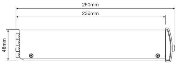
text_image
250mm 236mm 48mm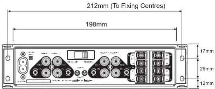
text_image
212mm (To Fixing Centres) 198mm 17mm 25mm 12mm(To Fixing Centres)
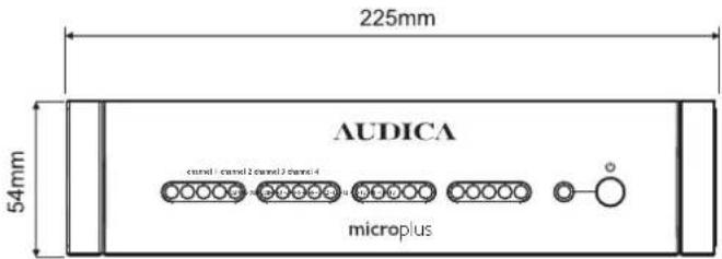
text_image
225mm AUDICA 54mm control1 control2 control3 control4 microplus
text_image
CAUTION! RISK OF ELECTRIC SHOCK DO NOT OPEN TO REDUCE THE RISK OF ELECTRIC SHOCK DO NOT REMOVE COVER NO USER-REMOVEABLE PARTS INSIDE REFER SERVICING TO QUALIFIED PERSONNEL
text_image
This symbol indicates that there are important operating and maintenance instructions in the literature accompanying this unit. This symbol indicates that dangerous voltage constituting a risk of electric shock is present within this unit.Read these instructions.
Keep these instructions.
Heed all warnings.
Follow all instructions.
1. SERVICING
Do not attempt to service this product yourself as opening covers or panels may expose you to dangerous voltages or other hazards. Refer all servicing to qualified personnel.
Where replacement parts are required be sure the service technician has used replacements supplied by the manufacturer or have the same characteristics as the original part. Use of unsuitable parts could cause fire, electric shock or other hazards and may void any warranty or guarantee.
The technician must perform any safety checks to test the performance of the product upon completion of any repairs.
2. PRECAUTIONS
WARNING - To reduce the risk of electric shock do not remove any panels or covers. There are no user serviceable parts in this product.
WARNING - To reduce the risk of electric shock, do not expose this product to rain or moisture.
READ ALL INSTRUCTIONS before attempting to install or use the product.
RETAIN INSTRUCTIONS for future reference.
WATER AND MOISTURE - The product should be kept away from water, for example sinks, bath tubs, wet areas and the like.
OBJECT OR LIQUID ENTRY - Do not insert any object or liquid into the openings in the product as this may cause electric shock or malfunction.
HEAT - The product should be kept away from any heat sources such as radiators, stoves or fires.
MOVING/TRANSPORTING THE PRODUCT - All product should be packed in its original packaging for moving from location to location.
OVERLOADING - Never overload mains outlets, extension cables or multi-way plug extensions as this may cause fire or electric shock.
POWER CORD PROTECTION - Power supply cords must be routed away from areas where they are likely to be walked on or squashed by furniture. Also pay attention to the placement of extension leads or multi-way extension leads.
LIGHTNING - For added protection of the product during lightning storms or extended periods of non use, unplug your whole system from the mains outlet and disconnect your antenna. This will protect your system from damage due to lightning strikes and power surges.
text_image
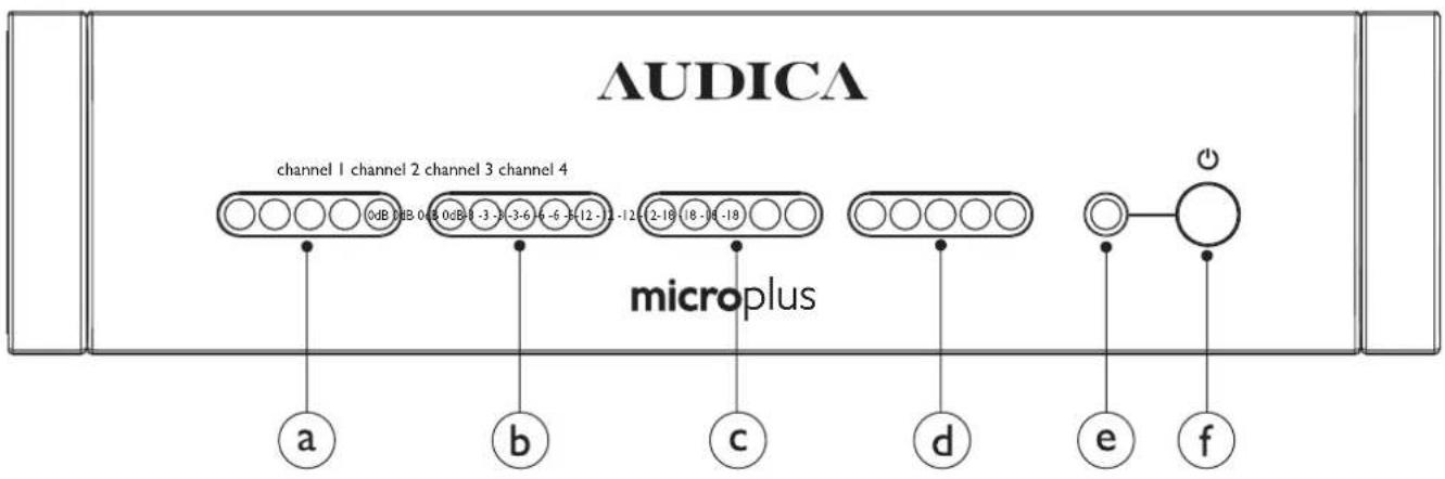
AUDICA channel 1 channel 2 channel 3 channel 4 microplus a b c d e fa - Channel 1 output level meter. The red 0dB indicator lights when the limiter function starts to operate.
b - Channel 2 output level meter. The red 0dB indicator lights when the limiter function starts to operate.
c - Channel 3 output level meter. The red 0dB indicator lights when the limiter function starts to operate.
d - Channel 4 output level meter. The red 0dB indicator lights when the limiter function starts to operate.
e - Power on indicator. This will light constant blue when the power is on. f - Power on/off button. This is a true mechanical power switch (not a standby mode). Its position is "remembered" even during mains power failure.
text_image
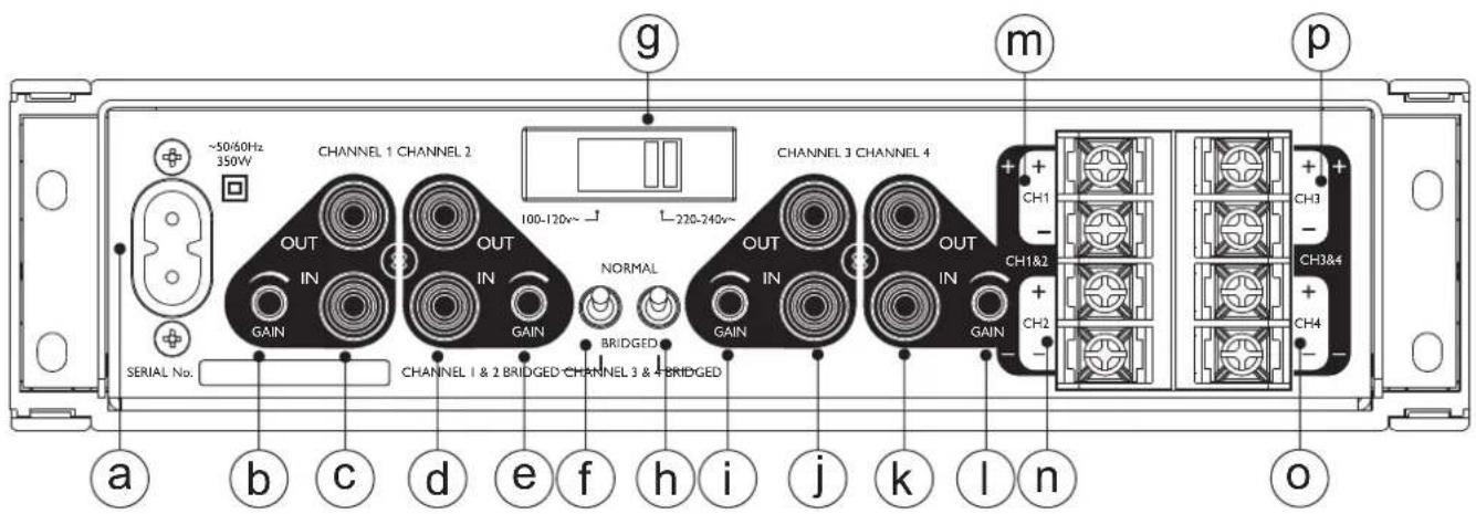
~50/60Hz 350W CHANNEL 1 CHANNEL 2 OUT IN GAIN SERIAL No. CHANNEL 1 & 2 BRIDGED CHANNEL 3 & 4 BRIDGED OUT IN GAIN NORMAL BRIDGED CHANNEL 3 CHANNEL 4 OUT IN GAIN CHANNEL 3 CHANNEL 4 220-240v~ g m CH1 - CH1&2 + - CH2 + - CH3 - CH3&4 + - CH4 - o a b c d e f h i j k l na) Mains power input
b) Channel 1 gain control. Turn anti-clockwise to reduce gain and clockwise to increase gain
c) Channel 1 line level phono input and paralleled output
d) Channel 2 line level phono input and paralleled output
e) Channel 2 gain control. Turn anti-clockwise to reduce gain and clockwise to increase gain
f) Channel 1 + 2 mode switch. In the "normal" position, channels 1 and 2 operate as independent channels with a 4 Ohm minimum load capability. In the "bridged" position channels 1 and 2 operate as a single high output channel with an 8 Ohm minimum load capability. See wiring diagram for connection details.
g) Mains voltage switch. Ensure that this switch is set to the correct mains voltage for your region – failure to do so will result in damage to the unit and invalidate the warranty.
h) Channel 3 + 4 mode switch. In the "normal" position, channels 3 and 4 operate as independent channels with a 4 Ohm minimum load capability. In the "bridged" position channels 3 and 4 operate as a single high output channel with an 8 Ohm minimum load capability. See wiring diagram for connection details.
i) Channel 3 gain control. Turn anti-clockwise to reduce gain and clockwise to increase gain
j) Channel 3 line level phono input and paralleled output
k) Channel 4 line level phono input and paralleled output
I) Channel 4 gain control. Turn anti-clockwise to reduce gain and clockwise to increase gain
m) Loudspeaker output terminals for channel 1
n) Loudspeaker output terminals for channel 2
o) Loudspeaker output terminals for channel 4
p) Loudspeaker output terminals for channel 3
Bridge Mode
Channels 1 and 2 operate as independent channels with a 4 Ohm minimum load capability. In the "bridged" position channels 1 and 2 operate as a single high output channel with an 8 Ohm minimum load capability. See wiring diagram for connection details.
To bridge channels 1 & 2:
Note: only the channel 1 level meter will operate.
text_image
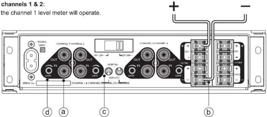
channels 1 & 2: the channel 1 level meter will operate. -50/60Hz 3.8W CHANNEL 1 CHANNEL 2 OUT IN GAIN CHANNEL 1 & 2 BRIDGED CHANNEL 3 & 4 BRIDGED CHANNEL 3 CHANNEL 4 OUT IN GAIN CHANNEL 1 & 2 BRIDGED CHANNEL 3 & 4 BRIDGED SERIAL No. d a c b + - + - + - + - + - + - + - + - + - + - + - + - + - + -a - Apply the input signal to channel 1 only. Leave channel 2 input disconnected.
b - Connect the loudspeaker/s to the two terminals as marked on the rear panel (positive at very top and negative at very bottom).
c - Set the mode switch for channels 1 & 2 to bridged position.
d - Gain is adjusted with the channel 1 gain control only (channel 2 gain control has no effect)
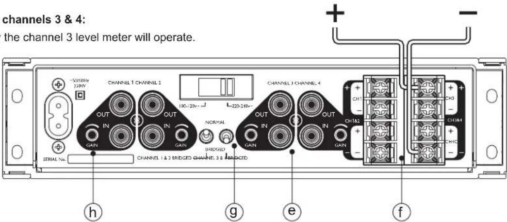
To bridge channels 3 & 4:
Note: Only the channel 3 level meter will operate.
text_image
channels 3 & 4: the channel 3 level meter will operate. + - CHANNEL 1 CHANNEL 2 OUT IN GAIN CHANNEL 1 & 2 BRIDGED CHANNEL 3 & BRIDGED CHANNEL 3 CHANNEL 4 OUT IN GAIN CHANNEL 3 CHANNEL 5 OUT IN GAIN CHANNEL 3 CHANNEL 6 OUT IN GAIN CHANNEL 3 CHANNEL 7 OUT IN GAIN CHANNEL 3 CHANNEL 8 OUT IN GAIN CHANNEL 3 CHANNEL 9 OUT IN GAIN CHANNEL 3 CHANNEL 10 OUT IN GAIN CHANNEL 3 CHANNEL 11 OUT IN GAIN CHANNEL 3 CHANNEL 12 OUT IN GAIN CHANNEL 3 CHANNEL 13 OUT IN GAIN CHANNEL 3 CHANNEL 14 OUT IN GAIN CHANNEL 3 CHANNEL 15 OUT IN GAIN CHANNEL 3 CHANNEL 16 OUT IN GAIN CHANNEL 3 CHANNEL 17 OUT IN GAIN CHANNEL 3 CHANNEL 18 OUT IN GAIN CHANNEL 3 CHANNEL 19 OUT IN GAIN CHANNEL 3 CHANNEL 20 OUT IN GAINe -Apply the input signal to channel 3 only. Leave channel 4 input disconnected.
f - Connect the loudspeaker/s to the two terminals as marked on the rear panel (positive at very top and negative at very bottom).
g - Set the mode switch for channels 3 & 4 to bridged position.
h - Gain is adjusted with the channel 3 gain control only (channel 4 gain control has no effect)
Fault conditions:
Under fault conditions such as short circuit, over-current (load impedance too low) and over temperature the level meter for the affected channels will show no signal (white lights extinguished) and the red "0dB" LED will light indicating protection is operating. All protection systems are auto-recovering (no latching of faults) so that normal operation resumes as soon as the fault condition is removed.
Please note that the protection systems are shared in pairs, channels 1 & 2 are paired and channels 3 & 4 are paired. Hence under a fault condition on channel 1, for example, both channels 1 & 2 will be shut down until the fault is cleared. Likewise, a fault on channel 4 would result in channels 3 & 4 shutting down etc.
Limiter operation:
The amplifier has a separate limiter for each channel and this has been carefully balanced to provide protection against clipping whilst still allowing the full output potential to be realised with music signals. Under conditions which would normally cause the output to clip the limiter will automatically reduce the gain to prevent audible distortion. Some momentary clipping of music transients will occur but this is generally inaudible and allows the perceived loudness to be greater than if all clipping were strictly eliminated.
The limiter provides valuable protection for both the loudspeakers and the listener's ears under overdrive conditions.
Optimising the output of your Microseries System
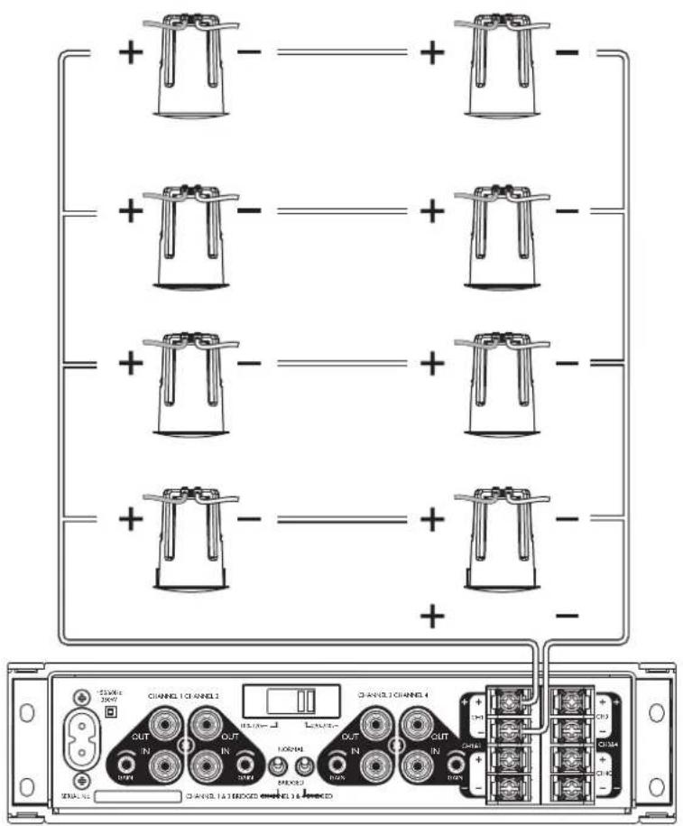
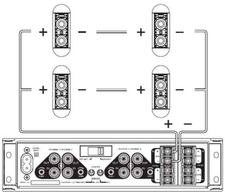
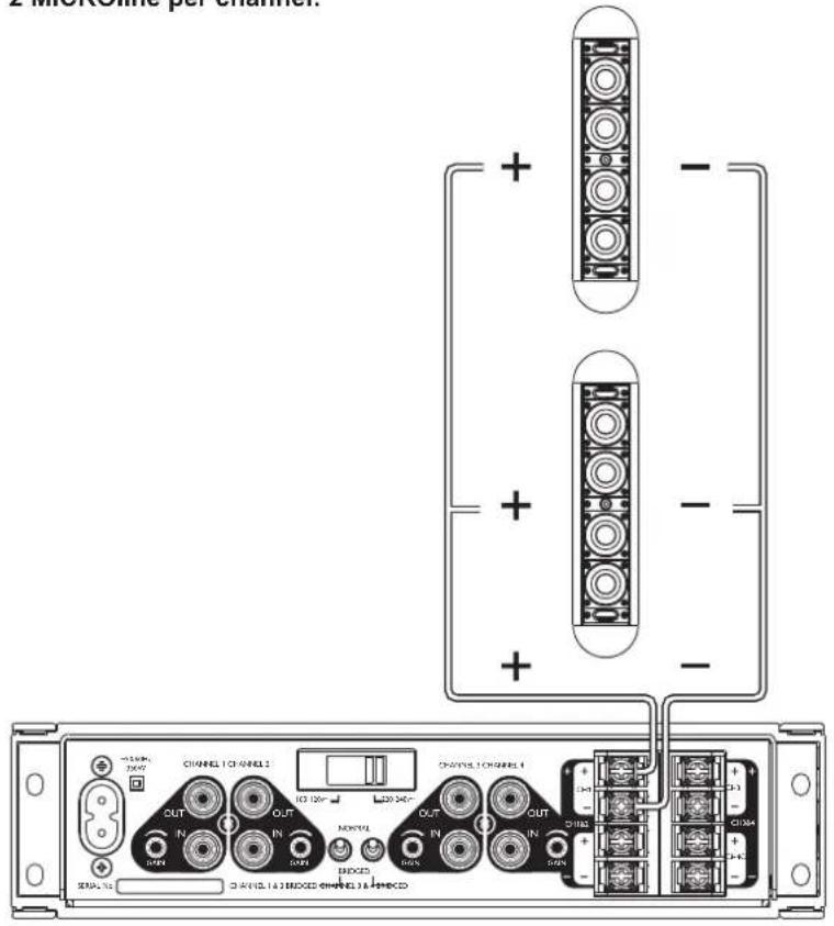
The following combinations drive the largest number of loudspeakers for the greatest area of coverage and use the 4 Ohm capability of the MICROplus for maximum output power:
8 MICROdot per channel:
text_image
Diagram of a multi-channel electronic device with labeled ports and connectors, showing connections between channels 1 to 4 and external ports.[2 x MICROdot series / 16 Dhm
[2 x MICROdot series / 16 Dhm
[2 x MICROdot series / 16 Dhm
[2 x MICROdot series / 16 Φhm
Wired in parallel =
8 MICROdot @ 4 Ghiven by 80W.
MICROdot per MICROplus:
With 4 channels this will give a total of
32 x MICROdot per MICROplus
4 MICROpoint per channel:
text_image
Diagram of a dual-chamber electronic device showing two connectors with labeled ports and connections, including OUT, ENDED, and CHADD labels.[2 x MICROpoint series / 8 Dhm
[2 x MICROpoint series / 8 Phm
Wired in parallel =
4 x MICROpoint @ 4 Ghiven by 80W.
MICROpoint per MICROplus:
With 4 channels this will give a total of
16 x MICROpoint per MICROplus
2 MICROline per channel:
text_image
2 MERCOSIPE PER CHANNEL. CHANNEL CHANNELS CHANNEL CHANNELS CHANNEL CHANNELS CHANNEL CHANNELS CHANNEL CHANNELS CHANNEL CHANNELS CHANNEL CHANNELS CHANNEL CHANNELS CHANNEL CHANNELS CHANNEL CHANNELS CHANNEL CHANNELS CHANNEL CHANNELS CHANNEL CHANNELS CHANNEL CHANNELS CHANNEL CHANNELS CHANNEL CHANNELS CHANNEL CHANNELS CHANNEL CHANNELS CHANNEL CHANNELS CHANNEL CHANNELS CHANNEL CHANNELS CHANNEL CHANNELS CHANNEL CHANNELS CHANNEL CHANNELS CHANNEL CHANNELS CHANNEL CHANNELS[1 x MICROline / 8]Dhm
[1 x MICROline / 8]Phm
Wired in parallel =
2 x MICROline @ 4 Ghimen by 80W.
MICROline per MICROplus:
With 4 channels this will give a total of
8 x MICROline per MICROplus
If less speakers are required, the 8 capability of the MICROplus may be the best solution. Ohm
4 MICROdot per channel:
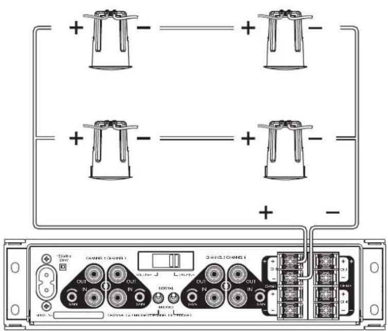
text_image
Diagram of a dual-channel electronic device with labeled ports and connectors, showing connections between ports with polarity indicators.[2 x MICROdot series / 16]Ohm
[2 x MICROdot series / 16]Ohm
Wired in parallel =
4 MICROdot @ 8 Ghimen by 40W.
MICROdot per MICROplus:
With 4 channels this will give a total of
16 x MICROdot per MICROplus
2 MICROpoint per channel:
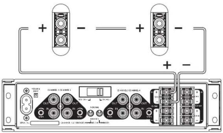
text_image
Diagram of a network device rear panel with labeled ports and connectors, showing connections between channels and ports.[2 x MICROpoint in series = 8 Phm
=
2 x MICROpoint @ 8 @hiven by 40W
MICROpoint per MICROplus:
With 4 channels this will give a total of
8 x MICROpoint per MICROplus
1 MICROline per channel:
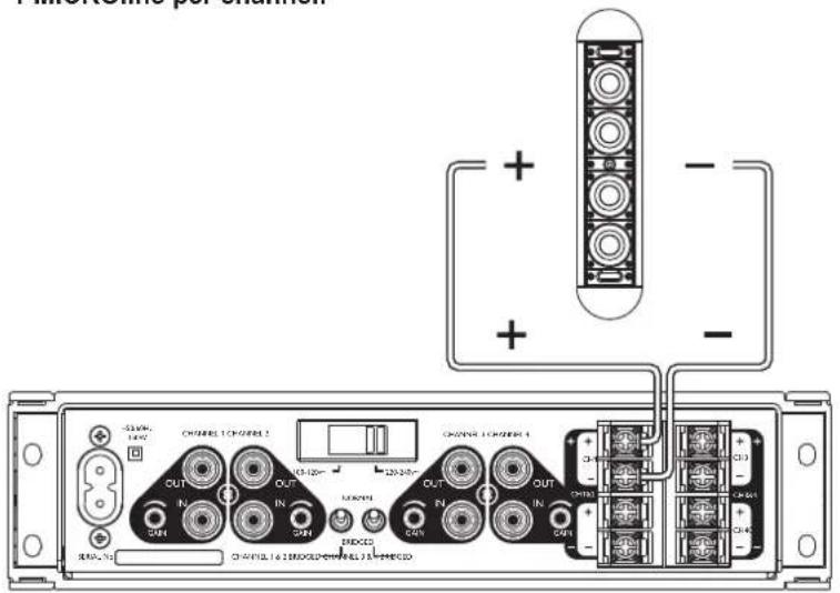
text_image
Ameristar per situation + - + - CHANNEL 1 CHANNEL 2 CHANNEL 1 CHANNEL 3 OUT IN IN OUT IN IN OUT IN IN CHANNEL 1 & 2 ENDED CHANNEL 3 ENDED CHANNEL 1 & 2 ENDED CHANNEL 3 ENDED[1 x MICROline / 8 Phm
=
1 x MICROline @ 8Driven by 40W.
MICROline per MICROplus:
With 4 channels this will give a total of
4 x MICROline per MICROplus
Notes:
1) Remember, a MICROzone is required in every Audica Professional system to provide the correct EQ and filtering for MICROseries loudspeakers. The MICROzone + MICROplus combination provides a powerful BGM or AV system and you can still use the two amplifier channels of the MICROzone to drive further loudspeakers. The MICROzone is also providing all control and input functions and Sub output. The MICROplus is a straight gain amplifier with no EQ, so connects to the MICROzone's 'Line Out EQ' output.
2) In any series/parallel combination, always aim to raise impedance with the series pairs as a first consideration. This means that in the event of any loudspeaker failure only one series pair will be lost and the remaining parallel impedance load on the amplifier is increased and the amplifier is not subjected to a lowering of impedance which could cause it to operate its protection.
3) Any combination of the above 'per channel' suggestions can be used to provide mixed MICROdot, MICROpoint, MICROline systems. Do not mix different speaker types in any series connected speakers.
4) These suggestions are a guide for maximum system output. For background music this will often be well above the required sound level. Always consider the application requirements first, calculating the number and position of loudspeaker needed and the level they need to operate at. Then calculate the amplifier power/loudspeaker combination required
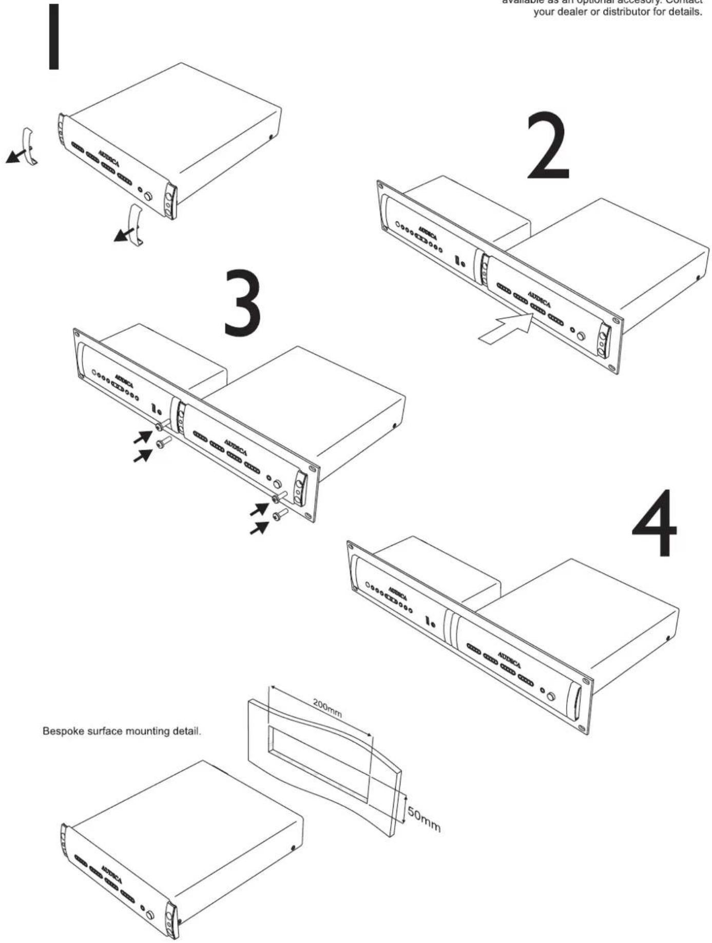
NOTE: Double width 2U rack adaptor available as an optional accesory. Contact your dealer or distributor for details.
Specification
Normal Mode (per channel):
Programme power output: 80W into 4, 40W into Ohm Ohm
Sine wave r.m.s. power output: 55W into 4, 280Vinto 3h (restricted by limiter operation)
Peak power output: 160W into 4, 80W into 8 Ohm Ohm
Gain: -infinity to 28dB (adjustable on rear panel)
Frequency Response: <10Hz to 35kHz (-3dB), less than 1dB down @ 20kHz
Signal to Noise ratio: 86dB (22Hz to 22kHz), 90dB (A-weighted)
THD: <0.03% (at 1kHz and 25W), <1% (20Hz-20kHz) all output levels
Input level for 55W output: 610mV r.m.s. at maximum gain setting (limiter operation begins)
Input impedance: 10k Ohm
Maximum input level: 30V r.m.s.
Bridge Mode (per pair of channels):
Programme power output: 160W into 8 Ohm
Sine wave r.m.s. power output: 110W into 8 (restricted by limiter operation)
Peak power output: 320W into 8 Ohm
Gain: -infinity to 34dB (adjustable on rear panel)
Frequency Response: <10Hz to 35kHz (-3dB), less than 1dB down @ 20kHz
Signal to Noise ratio: 86dB (22Hz to 22kHz), 90dB (A-weighted)
THD: <0.03% (at 1kHz and 50W), <1% (20Hz-20kHz) all output levels
Input level for 110W output: 610mV r.m.s. at maximum gain setting (limiter operation begins)
Input impedance: 10k Ohm
Maximum input level: 30V r.m.s.
Mains input:
Voltage: 100-120Va.c. or 220-240Va.c. (switch on rear)
Frequency: 50 or 60Hz
Idle power consumption: 27W
Typical operating power: 100W (Music signal at high level - limiter operating)
Maximum input power: 350W (Full power sine wave on all channels)
Protection:
Over-current (low impedance loads), short-circuit, over-temperature, input overload, anti-clipping limiter.
Display:
LED bargraph showing input level, -18dB, -12dB, -6dB, -3dB, 0dB.
0dB indicates limiter activation.
Cooling:
Passively cooled by convection. Air enters at sides and exits through top of case.
Please allow at least 7cm of clearance above top of case and 4cm each side.