MixWizard WZ4-12 - Mixer ALLEN & HEATH - Free user manual and instructions
Find the device manual for free MixWizard WZ4-12 ALLEN & HEATH in PDF.


| Product Type | Analog Mixing Console |
| Brand | Allen & Heath |
| Model | MixWizard WZ4-12 |
| Number of Channels | 12 Mono + 2 Stereo |
| Buses | 4 Group Buses + L/R |
| Equalization | 3-Band EQ with Sweepable Mid |
| Built-in Effects | None (External FX loop available) |
| Inputs | 12 XLR/TRS Combo, 2 Stereo RCA |
| Outputs | Main L/R XLR, 4 Group XLR, Monitor, Phones |
| Phantom Power | Global +48V |
| Dimensions (W x D x H) | 620 x 450 x 150 mm |
| Weight | 12 kg |
| Power Supply | Internal, 100-240V AC, 50/60Hz |
| Power Consumption | 60 W |
| Cleaning | Use a dry soft cloth; avoid liquids and solvents |
| Safety | Class I equipment; ground connection essential |
| Spare Parts / Repairability | Modules and ICs available; service by qualified technicians |
| General Information | Professional analog mixer for live sound and recording |
Frequently Asked Questions - MixWizard WZ4-12 ALLEN & HEATH
User questions about MixWizard WZ4-12 ALLEN & HEATH
0 question about this device. Answer the ones you know or ask your own.
Ask a new question about this device
Download the instructions for your Mixer in PDF format for free! Find your manual MixWizard WZ4-12 - ALLEN & HEATH and take your electronic device back in hand. On this page are published all the documents necessary for the use of your device. MixWizard WZ4-12 by ALLEN & HEATH.
USER MANUAL MixWizard WZ4-12 ALLEN & HEATH
natural_image
Close-up of a black audio workstation with multiple audio channels and control knobs (no visible text or labels)MixWizard WZ ^4 16:2 and WZ ^4 12:2
USER GUIDE
Publication AP8665
Limited One Year Warranty
This product is warranted to be free from defects in materials or workmanship for period of one year from the date of purchase by the original owner.
To ensure a high level of performance and reliability for which this equipment has been designed and manufactured, read this User Guide before operating. In the event of a failure, notify and return the defective unit to ALLEN & HEATH Limited or its authorised agent as soon as possible for repair under warranty subject to the following conditions
Conditions Of Warranty
The equipment has been installed and operated in accordance with the instructions in this User Guide.
The equipment has not been subject to misuse either intended or accidental, neglect, or alteration other than as described in the User Guide or Service Manual, or approved by ALLEN & HEATH.
Any necessary adjustment, alteration or repair has been carried out by ALLEN & HEATH or its authorised agent.
This warranty does not cover fader wear and tear.
The defective unit is to be returned carriage prepaid to ALLEN & HEATH or its authorised agent with proof of purchase.
Units returned should be packed to avoid transit damage.
In certain territories the terms may vary. Check with your ALLEN & HEATH agent for any additional warranty which may apply.
CE
This product complies with the European Electromagnetic Compatibility directive 2004/108/EC and the European Low Voltage directive 2006/95/EC.
This product has been tested to EN55103 Parts I & 2 2009 for use in Environments E1, E2, E3, and E4 to demonstrate compliance with the protection requirements in the European EMC directive 2004/108/EC. During some tests the specified performance figures of the product were affected. This is considered permissible and the product has been passed as acceptable for its intended use. Allen & Heath has a strict policy of ensuring all products are tested to the latest safety and EMC standards. Customers requiring more information about EMC and safety issues can contact Allen & Heath.
NOTE: Any changes or modifications to the console not approved by Allen & Heath could void the compliance of the console and therefore the users authority to operate it.
Allen & Heath WZ ^4 16:2 and 12:2 User Guide AP8665 Issue I
Copyright © 2013 Allen & Heath Limited. All rights reserved
Allen & Heath Limited
Kernick Industrial Estate, Penryn, Cornwall, TR10 9LU, UK
http://www.allen-heath.com
WARNING - Read the following before proceeding :

text_image
CAUTION RISK OF ELECTRIC SHOCK DO NOT OPENATTENTION: RISQUE DE CHOC ELECTRIQUE - NE PAS OUVRIR
| Read instructions: | Retain these safety and operating instructions for future reference. Adhere to all warnings printed here and on the console. Follow the operating instructions printed in this User Guide. |
| Do not remove cover: | Operate the console with its covers correctly fitted. Disconnect mains power by unplugging the power cord if the cover needs to be removed for setting internal options. Refer this work to competent technical personnel only. |
| Power sources: | Connect the console to a mains power unit only of the type described in this User Guide and marked on the rear panel. Use the power cord with sealed mains plug appropriate for your local mains supply as provided with the console. If the provided plug does not fit into your outlet consult your service agent for assistance. |
| Power cord routing: | Route the power cord so that it is not likely to be walked on, stretched or pinched by items placed upon or against it. |
Grounding: Do not defeat the grounding and polarisation means of the power cord plug. Do not remove or tamper with the ground connection in the power cord

WARNING: This equipment must be earthed.
| Water and moisture: | To reduce the risk of fire or electric shock do not expose the console to rain or moisture or use it in damp or wet conditions. Do not place containers of liquids on it which might spill into any openings. |
| Ventilation: | Do not obstruct the ventilation slots or position the console where the air flow required for ventilation is impeded. If the console is to be operated in a rack unit or flightcase ensure that it is constructed to allow adequate ventilation. |
| Heat and vibration: | Do not locate the console in a place subject to excessive heat or direct sunlight at this could be a fire hazard. Locate the console away from any equipment which produces heat or causes excessive vibration. |
| Servicing: | Switch off the equipment and unplug the power cord immediately if it is exposed to moisture, spilled liquid, objects fallen into the openings, the power cord or plug become damaged, during lightning storms, or if smoke, odour or noise is noticed. Refer servicing to qualified technical personnel only. |
| Installation: | Install the console in accordance with the instructions printed in this User Guide. Do not connect the output of power amplifiers directly to the console. Use audio connectors and plugs only for their intended purpose. |
Important Mains plug wiring instructions.
The console is supplied with a moulded mains plug fitted to the AC mains power lead. Follow the instructions below if the mains plug has to be replaced. The wires in the mains lead are coloured in accordance with the following code:

The wire which is coloured Green and Yellow must be connected to the terminal in the plug which is marked with the letter E or with the Earth symbol. This appliance must be earthed.
The wire which is coloured Blue must be connected to the terminal in the plug which is marked with the letter N.
The wire which is coloured Brown must be connected to the terminal in the plug which is marked with the letter L.
Ensure that these colour codes are followed carefully in the event of the plug being changed.
General Precautions
Damage :
To prevent damage to the controls and cosmetics avoid placing heavy objects on the control surface, scratching the surface with sharp objects, or rough handling and vibration.
Environment :
Protect from excessive dirt, dust, heat and vibration when operating and storing. Avoid tobacco ash, smoke, drinks spillage, and exposure to rain and moisture. If the console becomes wet, switch off and remove mains power immediately. Allow to dry out thoroughly before using again.
Cleaning :
Avoid the use of chemicals, abrasives or solvents. The control panel is best cleaned with a soft brush and dry lint-free cloth. The faders, switches and potentiometers are lubricated for life. The use of electrical lubricants on these parts is not recommended. The fader and potentiometer knobs may be removed for cleaning with a warm soapy solution. Rinse and allow to dry fully before refitting them.
Transporting :
The console may be transported as a free-standing unit or mounted in a rack or flightcase. Protect the controls from damage during transit. Use adequate packing if you need to ship the unit.
Hearing :
To avoid damage to your hearing do not operate any sound system at excessively high volume. This also applies to any close-to-ear monitoring such as headphones. Continued exposure to high volume sound can cause frequency selective or wide range hearing loss.
Introduction
Welcome to the Allen & Heath WZ ^4 , the latest generation of the popular MixWizard series of compact audio mixing consoles. We have tried to keep this user guide brief and to the point. Please read it fully before starting. Included is information on installing, connecting and operating the console, panel drawings, system block diagram and technical specification. For further information on the basic principles of audio system engineering, please refer to one of the specialist publications and resources available from bookshops, audio equipment dealers and the Internet.
Whilst we believe the information in this guide to be reliable we do not assume responsibility for inaccuracies. We also reserve the right to make changes in the interest of further product development.
We are able to offer further product support through our world-wide network of approved dealers and service agents. You can also access our Web site on the Internet for information on our full product range, our company pedigree, assistance with your technical queries, our contact details or simply to chat about audio matters (www.allen-heath.com) To help us provide the most efficient service please keep a record of your console serial number, and date and place of purchase to be quoted in any communication regarding this product.
Contents
Warranty 2 Console Connectors 13
Safety Instructions .... 3 Mono Input Channel .... 15
General Precautions 4 Stereo Input Channel 17
Introduction to this Guide .... 5 Stereo Effects Channel .... 18
Front Panel Layout 6 Master Section 19
Introducing the MixWizard 7 Gain Structure 21
Installing the Console 8 Specifications 22
Connecting Power 9 System Block Diagrams 24
Connection Pinouts and Cables 10 User Options 26
Audio Connections ...... 11 Cue Sheets ...... 29
Connector Panel Layouts 12
text_image
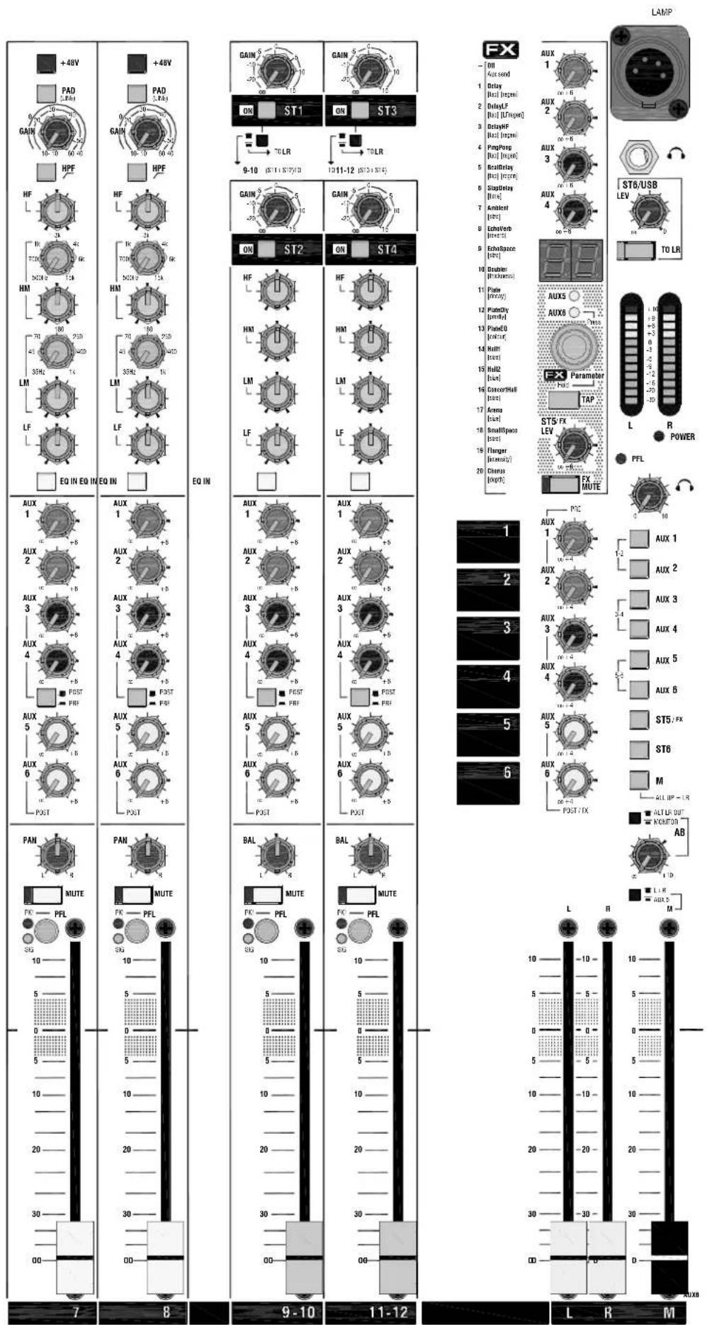
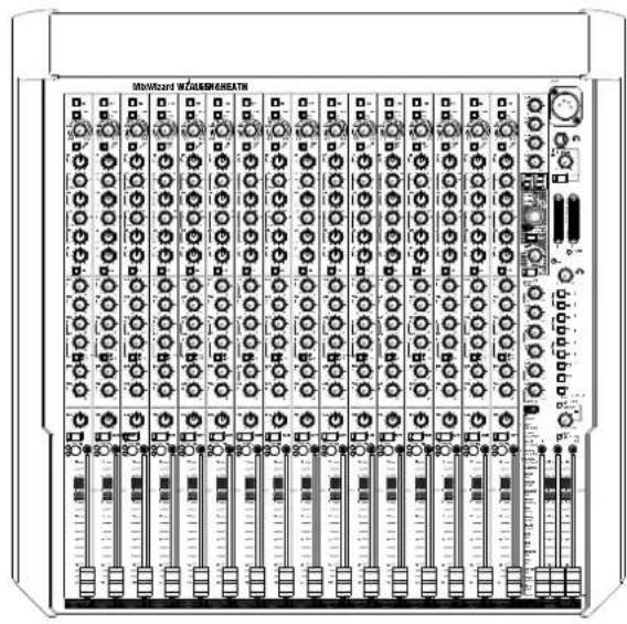
LAMP +48V PAD 5.4kV GAIN 10-10 00-40 HPF HF 1k 700 200 HM 70 LM LF EQ IN EQ IN EQ IN EQ IN AUX 1 AUX 2 AUX 3 AUX 4 AUX 5 AUX 6 PAN L MUTE FK PFL SIG 10 5 0 5 10 20 30 00 +5 9 - 10 11 - 12 L R M L ST6/USB LEV TO LR FX AUX 1 1 Delay [Hz] [Hz] 2 Delay,F [Hz] [Hz] 3 Delay,HF [Hz] [Hz] 4 Ping/Porp [Hz] [Hz] 5 Rect/Bitay [Hz] [Hz] 6 Sist/Bitay [Hz] 7 Ambient [Hz] 8 Echo/Verb [Hz] 9 Echo/Space [Hz] 10 Doublex [MHz] 11 Plate [MHz] 12 Plate,Dy [MHz] 13 Plate,CO [MHz] 14 Roll [Hz] 15 Roll2 [Hz] 16 CancerHall [Hz] 17 Arena [Hz] 18 Small/Space [Hz] 19 Flanger [MHz] 20 Champs [MHz] FX PMTE AUX 5 AUX 6 FX Parameter TAP ST5-FX LEV L R POWER PFL 1 AUX 1 AUX 2 AUX 3 AUX 4 AUX 5 AUX 6 ST5-FX ST6 M ALT LR OUT KONTOON AB L R M BAL MUTE PE PFL PE PFL PE PFL PE PFL PE PFL PE PFL PE PFL PE PFL PE PFL PE PFL PE PFL PE PFL PE PFL PE PFL PE PFL PE PFL PE PFL PE PFL PE PFL PE PFL PE PFL PE PFL PE PFL PE PFL PE PFL PE PFL PE PFL PE PFL PE PFL PE PFL PE PFL PE PFL PE PFL PE PFL ST1 ST3 9 - 10 ST1 + ST2 ST3 + ST4 ST5 - ST6 / USB LEV TO LRThe Allen & Heath MixWizard series of consoles includes several models. This user guide describes the WZ ^4 16:2 and WZ ^4 12:2 stereo models. For further information on the MixWizard series please refer to the Allen & Heath web site.
natural_image
Front view of a multi-chamber industrial control unit with multiple modules and indicator lights (no readable text or symbols)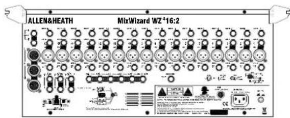
text_image
ALLEN&HEATH MixWizard WZ*16:2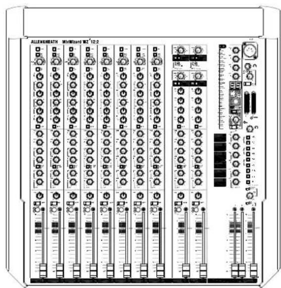
text_image
ALLENSHEATH Microband WZ 12.2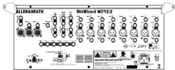
text_image
ALLEN & HEATH MirWizard WZ412:2The MixWizard is a compact console designed for professional live sound mixing. It is built to the same high standards as our top of the range consoles, with individual circuit cards, potentiometers nutted to the panel for absolute strength, steel chassis, and no compromise circuit design ensuring the finest sonic performance.
The console can be operated free standing or in a 19" rack or flightcase. It is supplied with protective side trims fitted. These can be removed for rack mounting. The rear connector pod can be easily rotated for rear facing or underside connectors when rack mounted.
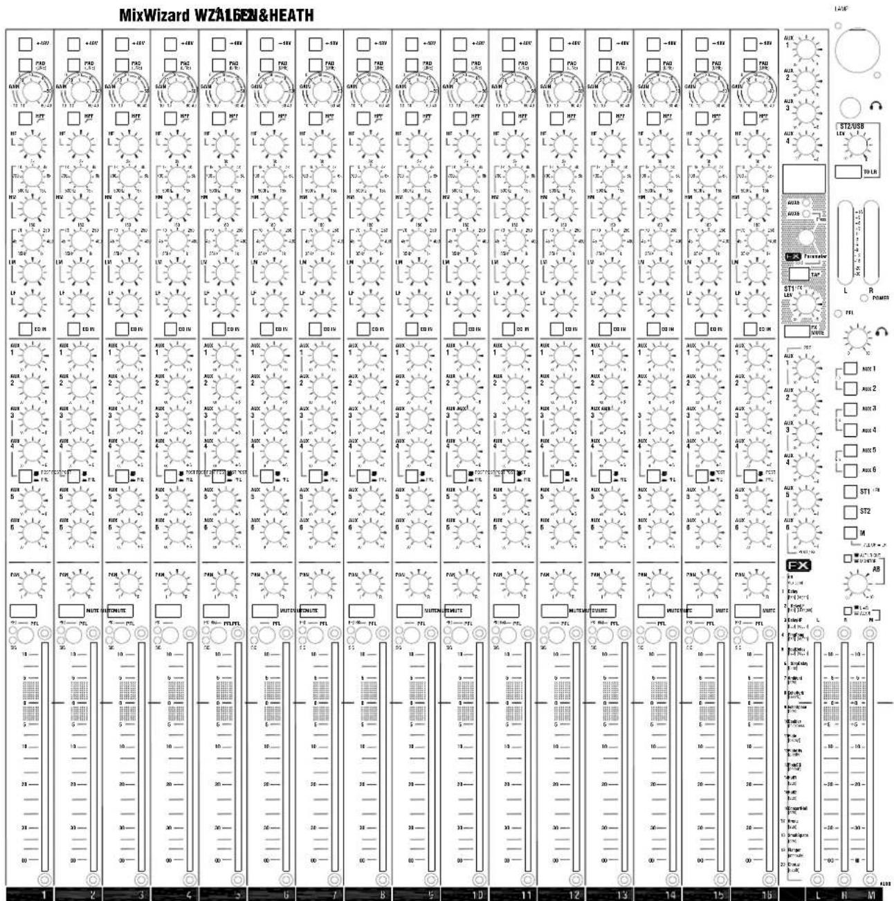
Both models feature a 4 band semi-parametric EQ and high pass filter per mic/line channel, 6 aux sends with combinations of pre/post switching, 100mm faders, a built-in dual effects processor with adjustable parameter control, dedicated mono output with separate fader and innovative operating mode for aux fed sub systems, additional AB stereo output, comprehensive metering, engineers monitoring and a lamp socket.
The WZ ^4 16:2 provides 16 mono mic/line inputs and 2 stereo return inputs, a total of 20 input connections. The WZ ^12:2 provides 8 mono mic/line inputs, 2 full channel dual stereo inputs, and 2 stereo return inputs, a total of 20 input connections.
The base of the console can be removed to access a host of internal user selectable options. These set user preference for the aux, direct output and AB sources.
The aux outputs are impedance balanced but may be electronically balanced if required by fitting an optional part. A kit is also available to fit an optional USB2 output card which allows the console to be linked to a computer for multitrack recording.
An Allen & Heath LEDlamp gooseneck lamp with built-in dimmer can also be added for lighting the console in low light conditions.
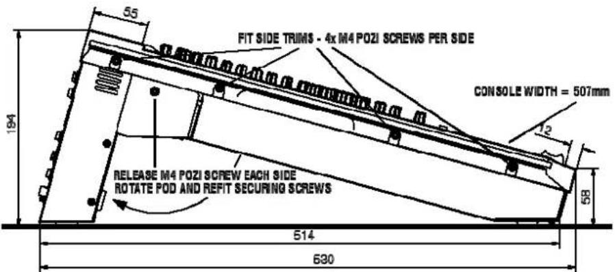
Free Standing
The console is supplied ready for free standing operation with its side trims fitted and connector pod positioned for rear access. If you are converting from rack to free standing then make sure the pod is correctly rotated and secured, and the side trims fitted as shown:
text_image
FIT SIDE TRIMS - 4x M4 POZI SCREWS PER SIDE CONSOLE WIDTH = 507mm RELEASE M4 POZI SCREW EACH SIDE ROTATE POD AND REFIT SECURING SCREWS 514 69019" Rack Mount
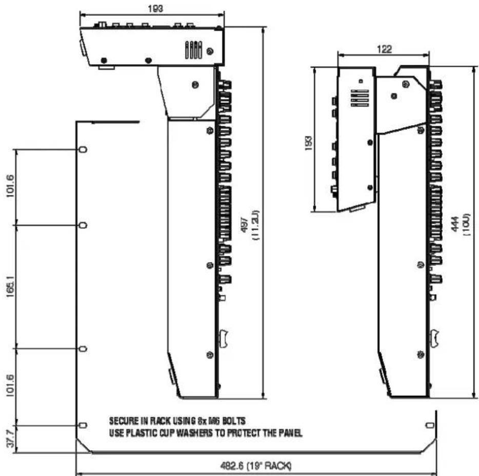
For rack mounting, remove the two side trims and rotate the pod into the connector position preferred. Allow enough space for the cables and connectors behind the console.
text_image
193 497 (11.2U) 101.6 165.1 101.6 37.7 SECURE IN RACK USING 8x MG BOLTS USE PLASTIC CUP WASHERS TO PROTECT THE PANEL 482.6 (19" RACK) 122 193 444 (10U)
Do not transport the console with its connector pod securing screws removed. Do not attempt to remove the connector pod from the console. Do not obstruct the ventilation slots. Allow adequate space around the console for air flow. If the side trims are to be removed, do not refit their fixing screws to the unit. Retain and store these in case the trims need to be refitted in the future.
text_image
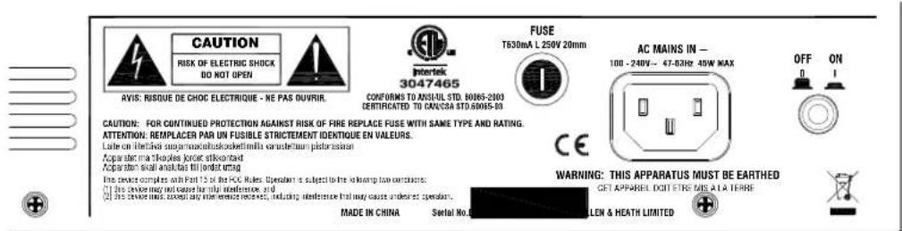
CAUTION RISK OF ELECTRIC SHOCK DO NOT OPEN AFIS: RISQUE DE CHOC ELECTRIQUE - NE PAS OUVRIR. INTERTK 3047465 CONFORMS TO ANSUL STD. 8065-2003 CERTIFICATED TO CANCSA STD.8065-03 FUSE T630mA L 250V 20mm AC MAINS IN - 100 - 240V ~ 67-52Hz 40W MAX OFF ON CAUTION: FOR CONTINUED PROTECTION AGAINST RISK OF FIRE REPLACE FUSE WITH SAME TYPE AND RATING. ATTENTION: REMPLACER PAR UN FUSIBLE STRICTEMENT IDENTIQUE EN VALEURS. Late on inflective support/absorbing/koblet/milla varatechion plate/assort Apparable Bahamas Jordan allowed Apparable shall and has fill print temp. This device complies with Part 15 of the PC. Rules Operation is subject to the following two orders: ■ This device may not cause harmful interference, and ■ This device must except any other service received, including interference that may cause undesirable operation. WARNING: THIS APPARATUS MUST BE EARTHED GET APPAREL DOIT FERS MIS A LA TERRE MADE IN CHINA Serial No. C LEN & HEATH LIMITEDRead and understand the Important Safety Instructions printed at the start of this guide, and the warnings printed on the rear of the console. Check that your local mains supply is within the 100-240V operating voltage range allowed. Check that the correct mains lead with moulded plug has been supplied with your console. Make sure that the IEC mains plug is pressed fully into the panel socket before switching on.

Grounding
The connection to ground in an audio system is important for two reasons:
I. SAFETY - To protect the operator from high voltage electric shock, and
2. AUDIO PERFORMANCE - To minimise the effect of ground (earth) loops which result in audible hum and buzz, and to shield the audio signals from interference.
3. For safety it is important that all equipment grounds are connected to mains ground so that exposed metal parts are prevented from carrying high voltage which can injure or even kill the operator. Do not disconnect the ground connection in the mains lead. It is recommended that the system engineer check the continuity of the safety ground from all points in the system including microphone bodies, turntable chassis, equipment cases, rack metalwork and so on.
Switching the console on and off
It is good practice to turn power amplifiers off before switching the console and any other connected equipment on or off. This prevents any unexpected clicks or thumps when the equipment is powered up.

Turn amplifiers and powered speakers on last and off first.
To turn the console on, press the ON/OFF switch next to the IEC mains input socket. To turn the console off, press this switch again.
text_image
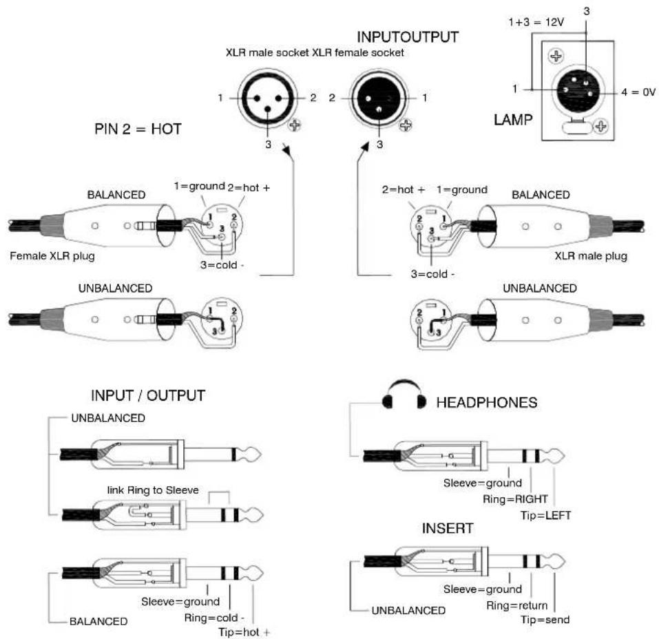
INPUTOUTPUT XLR male socket XLR female socket 1+3 = 12V 3 1 4 = 0V LAMP PIN 2 = HOT BALANCED 1=ground 2=hot + 1=ground 2=hot + 1=ground BALANCED Female XLR plug 3=cold - 3=cold - XLR male plug UNBALANCED UNBALANCED INPUT / OUTPUT UNBALANCED LINK Ring to Sleeve HEADPHONES Sleeve=ground Ring=RIGHT Tip=LEFT INSERT Sleeve=ground Ring=return UNBALANCED Ring=cold - Tip=hot + UNBALANCED Insert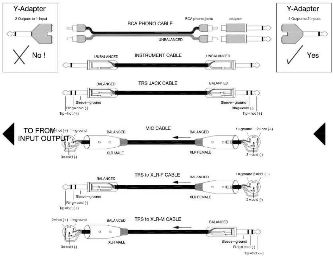
text_image
Y-Adapter 2 Outputs to 1 Input No! RCA PHONO CABLE RCA phono jacks adapter UNBALANCED UNBALANCED INSTRUMENT CABLE UNBALANCED Y-Adapter 1 Output to 2 Inputs ✓ Yes BALANCED TRS JACK CABLE BALANCED Sleeve=ground Ring=cold (-) Tip=hot (+) Sleeve=ground Ring=cold (-) Tip=hot (+) TO FROM INPUT OUTPUT M-hot (+) 1-ground BALANCED MIC CABLE BALANCED 1=ground 2=hot (-) XLR MALE XLR FEMALE 3=cold (-) BALANCED TRS to XLR-F CABLE BALANCED 1=ground 2=hot (+) XLR FEMALE 3=cold (-) Sleeve=ground Ring=cold (-) Tip=hot (+) 2=hot (-) 1=ground BALANCED TRS to XLR-M CABLE BALANCED Sleeve=ground Ring=cold (-) Tip=hot (+)The MixWizard uses professional grade 3 pin XLR and 1/4" TRS (3 pole) jack sockets. To ensure best performance, we recommend that you use high quality audio cables and connectors, and take time to check for reliable and accurate cable assembly. It is well known that most audio system problems are due to faulty or sub standard interconnecting leads. The following mating plugs may be used to connect audio signals to the console:
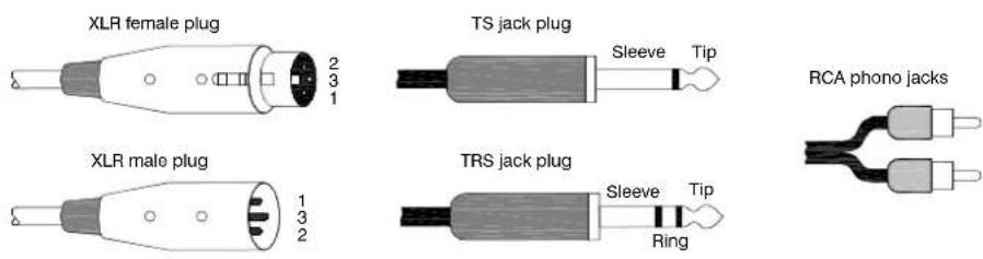
Avoid reversing + and - on balanced connections as this will result in reversed polarity (out of phase) signals which may cause signal cancellation effects.
Where long cables runs are required, balanced interconnections should be used. However, line level interconnections between more affordable 2-wire (signal, ground) unbalanced equipment and the console are unlikely to cause problems if the cables are kept shorter than 10 meters or so. Refer to the wiring diagrams on the opposite page.
Dealing with Ground Loops, Buzz and Interference
For optimum performance all audio signals should be referenced to a solid, noise-free ground (earth) point, frequently referred to as the 'star point' or 'clean earth'.
A ground loop is created when potential differences exist between grounds at different points in the system, and the signal has more than one path to ground. In most cases ground loops do not result in audible problems. Should you experience hum or buzz caused by a ground loop, check first that each piece of equipment has its own separate path to ground. If so, operate ground lift switches on connected equipment in accordance with the instruction manuals. Alternatively disconnect the cable screen at the destination end only. This breaks the offending loop while keeping the signal shielding down the length of cable.

WARNING For operator safety do not remove the ground (earth) connection in the ad of the console or connected equipment.
To avoid interference pickup keep audio cables away from mains power units and cables, thyristor dimmer units, computer equipment and mobile phones. Where this cannot be avoided, cross the cables at right angles to minimise interference
A note about balanced connections
A differentially balanced connection has two signal wires, signal + (hot) and signal - (cold) and a shield. The signal source generates positive going polarity down the + wire and negative polarity down the - wire. The destination input stage accepts the + signal on its non-inverting (+) input pin, but it inverts the - signal, adding it to the + signal. The result is that the wanted signal is boosted. Now examine what happens when unwanted interference (hum and noise) is induced into the cable. The noise is induced equally and with the same polarity into both wires. At the destination input the - wire signal gets inverted and added to the + signal. Because the polarity is the same on both input wires the noise cancels itself out at this input. For this interference rejection to work it is important that the source, the cable and the destination input are all balanced. Balancing provides greatest advantage with low level signals such as those produced by microphones.
An impedance balanced output provides similar interference rejection, but without the signal drive on the - wire. It does not generate a negative polarity signal at its - output. Instead, the - wire has no signal but is held at the same impedance as the + wire. This means that both wires pick up the noise equally resulting in cancellation as described above.
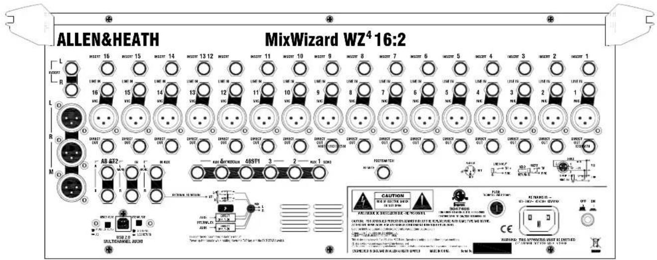
text_image
ALLEN&HEATH MixWizard WZ4 16:2 L INSERT 16 INSERT 15 INSERT 14 INSERT 13 12 INSERT INSERT 11 INSERT 10 INSERT 9 INSERT 8 INSERT 7 INSERT 6 INSERT 5 INSERT 4 INSERT 3 INSERT 2 INSERT 1 R L M IN LME IN LME IN LME IN LME IN LME IN LME IN LME IN LME IN LME IN LME IN LME IN LME IN LME IN LME IN LME IN LME IN LME IN LME IN LME IN LME IN LME IN LME IN LME IN LME IN LME IN LME IN LME IN LME IN LME IN LME IN LME IN LME IN LME IN LMEIN R R DIRECT OUT DIRECT OUT DIRECT OUT DIRECT OUT DIRECT OUT DIRECT OUT DIRECT OUT DIRECT OUT DIRECT OUT M A B &T2 I M F M A D C K M A D C D E X E X E X E X E X E X E X E X E X E X E X E X E X E X E X E X E X E X E X E X E X E X E X E X E X E X E X E X E X E X E X E X E X E X E X E X E X E X E X E X E X E X E X E X E X E X E X E X E X E X E USB 2.0 MULTICHANGES AUDIO CAUTION MINI CHILLER MAXIMUM CHILLER MAXIMUM CHILLER MAXIMUM CHILLER MAXIMUM CHILLER MAXIMUM CHILLER MAXIMUM CHILLER MAXIMUM CHILLER MAXIMUM CHILLER MAXIMUM CHILLER MAXIMUM CHILLER MAXIMUM CHILLER MAXIMUM CHILLER MAXIMUM CHILLER MAXIMUM CHILLER MAXIMUM CHILLER MAXIMUM CHILLER MAXIMUM CHILLER
text_image
ALLEN&HEATH MixWizard WZ⁴12:2 A B M R O L L R R R R R R R R R R R R R R R R R R R R R R R R R R R R R R R R R R R R R R R R R R R R R R R R R R UW 6 - AUS 5 - AUS 4 - AUS 3 - AUS 2 - AUS 1 - AUS 0 USB 2.0 MULTIOMINEL AUDIO CAUTION FLEX TECHNOLOGY (EQUITY) (EQUITY) ACVACHING AIR CAN CHAPICUM (EQUITY) POWER R120000000000000000000000000000000000000000000000000000000000000000000000000000000000000000000000000000 COUNTERS: 11-12 ST15 IN ST14 IN ST13 IN ST12 IN ST11 IN ST10 IN ST9 IN ST8 IN ST7 IN ST6 IN ST5 IN ST4 IN ST3 IN ST2 IN ST1 IN 9 IN 8 IN 7 IN 6 IN 5 IN 4 IN 3 IN 2 IN 1 IN 0 HORSE OF COLDING WITH AC VENTURES BEANS OF COLDING WITH AC VENTURES ACVACHING AIR CAN CHAPICUM (EQUITY) POWER R120000000000000000000000000000000000000000000000000000000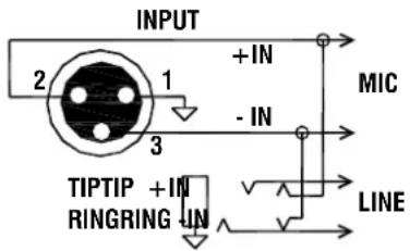
text_image
INPUT + IN MIC 2 1 - IN 3 TIPTIP + IN RINGRING IN LINEMIC / LINE IN The channel PAD (LINE) switch selects either the MIC XLR or the LINE TRS jack as the input source. The XLR is normalled through the TRS jack. This means that the XLR can be used for microphone or line level signals when nothing is plugged into the jack socket. Both inputs are balanced but can be wired to work with unbalanced signals when required.
WARNING: Do not connect unbalanced sources or cables to the XLR input when 48V phantom power is selected. To avoid loud clicks always turn the channel off by pressing MUTE when switching +48V on or off, and when plugging or unplugging cables.
flowchart
graph TD
    A["EXTERNAL FX RETURN"] --> B["L/M"]
    B --> C["ST1 R"]
    C --> D["+"]
    D --> E["MIX"]
    F["AUX5"] --> G["EFFECT OFF, 1-20"]
    H["INTERNAL FX"] --> I["EFFECT OFF, 1-20"]
    J["AUX6"] --> K["EFFECT OFF, 1-20"]
    G --> K
    I --> K
    K --> L["L R"]
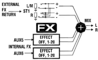
STEREO LINE IN The WZ ^4 12:2 has six stereo inputs comprising four channel inputs ST1,3 (unbalanced) and ST2,4 (balanced), and an additional two stereo returns ST5 (balanced) and ST6 (unbalanced). The WZ ^4 16:2 has two stereo return inputs ST1 (balanced) and ST2 (unbalanced). All inputs use TRS jacks. Unbalanced inputs automatically connect the TRS ring to ground for working with balanced sources. The L input is normalled through the R input to accept mono signals.
Note that the ST5 (WZ ^4 12:2) or STI (WZ ^4 16:2) stereo return input mixes with the internal effects processor return. This means that an external effects device fed from a different aux mix can mix with the internal processor to save input channels. Alternatively, you could turn the internal unit off and use the ST5 (STI) input with an external unit only if preferred.
flowchart
graph TD
    A["SEND"] --> B["INSERT"]
    C["RETURN"] --> B
    B --> D["TIP"]
    B --> E["RING"]
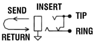
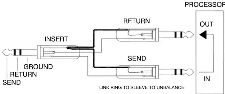
INSERT A single 3-pole TRS jack carries the unbalanced insert signal. Tip = send, Ring = return, Sleeve = common ground. The channel insert is post-HPF, pre-EQ and operates at 0dBu. The LR mix insert is pre-fader and operates at -2dBu. These should work fine with line level signal processing equipment such as compressors, outboard EQ, delay units and so on. An example of a suitable cable is shown here:
flowchart
graph TD
    A["Input"] --> B["INSERT"]
    B --> C["RETURN"]
    B --> D["SEND"]
    C --> E["PROCESOR OUT"]
    D --> F["PROCESOR IN"]
    G["Ground"] --> B
    H["SEND"] --> D
    I["LINK RING TO SLEEVE TO UNBALANCE"] --> C
    I --> D
DIRECT OUTPUT The mic/line channel direct output is available on an impedance balanced TRS jack. It is a line level signal operating at 0dBu. The source is set using an internal option jumper for each channel. The factory default setting is pre-fade (following the pre/post-EQ setting). This may be changed to post-fade if preferred.
The direct outputs provide a useful source for multitrack recording. Many users prefer pre-fade sends for this application so that the live show fader movements do not affect the recording which can be mixed later. Another application is channel effects sends. For example, a reverb unit may be dedicated to work with the lead vocalist channel only. Using a post-fade direct output instead of an aux send frees up that aux mix for other purposes.
L, R, M OUT The main console mix outputs are on balanced XLR. These produce +4dBu when the meters read '0'. The M output can be switched to provide a mono sum of the post-fade L and R signals, or the AUX6 output.
The L and R outputs typically feed the house PA system in live sound mixing, or a 2-track recorder in studio mixing. In mono mode, the M output can provide an additional feed for a mono fill speaker or zone, or be used as the main feed into a mono PA. Used with a mono PA the L and R mix can provide a pair of subgroups, each with routing using the channel PAN controls, inserts and faders. Configured to provide the AUX6 mix, the M output is ideal for driving a sub bass speaker system when working with an 'aux fed subs' PA. This provides the sub feed with its own per-channel mix on balanced XLR and with dedicated fader alongside the main LR faders for proper control of the house volume.
AB OUT A pair of impedance balanced TRS jacks can be configured to provide an additional LR mix or engineers monitor send. These operate at -2dBu line level. A front panel recessed 'mode' switch determines the source to the AB output. This may be set to follow the console monitor system and therefore feed an independent local stereo monitor or even engineers wedge speaker. When set to follow the LR mix, the factory default source is taken post LR fader. An internal option jumper is available to change this to pre LR fader.
The unique AB output feature provides the MixWizard with a host of possibilities... independent 2-track recording feed, broadcast feed, zone and delay fill feeds, local monitor, engineers wedge monitor and more.
AUX OUT 1-6 Each aux send is available on an impedance balanced TRS jack operating at -2dBu line level. An internal option is available to fit a balanced line driver IC to provide an electronically balanced output operating at +4dBu. Note that it is not usual to require this option as the impedance balanced standard drive provides significant interference rejection when feeding balanced equipment inputs.
The aux sends are typically used to feed stage monitors, effects devices such as reverb and delay, and for special mix requirements.
text_image
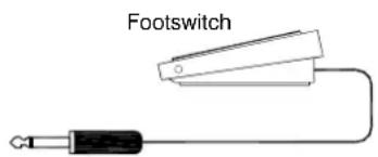
FootswitchFOOTSWITCH Mutes and unmutes the ST5 (ST1) effects return channel, ideal for bypassing the effects between songs. Note that this affects the internal processor and also any external effects device that may be plugged in to these return inputs. Use a momentary or latching footswitch as required. Shorting a TS or TRS jack tip to sleeve turns the mute on.
USB II OPTION A blank plate is fitted here as standard. The USB II option kit is available from Allen & Heath. Refer to OPTIONS later in this guide.

text_image
+48V PAD 3.1kΩ 0 GAIN 10 10 10 HPF HF L 70 250 250 1k HM 70 250 250 45 250 LM 65kΩ 1k LF L EQ IN AUX 1 AUX 2 AUX 3 AUX 4 PAST PST AUX 5 AUX 6 POS I PAN MUTE PCL PFL 10 5 0 5 10 20 30 00 1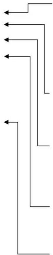
natural_image
Pure electrical circuit lines without any symbols+48V Switches +48VDC to the channel input XLR for powering microphones or DI boxes that need phantom power. The power is current limited through 6k8 ohm resistors to pins 2 and 3.

WARNING: Do not connect unbalanced sources or cables to inputs with phantom power selected. To avoid loud clicks always mute the channel before switching +48V on or off and when plugging or unplugging microphones.
PAD (LINE) Press this switch to select the channel TRS jack LINE input. Release the switch to select the XLR MIC input. The XLR normals through the TRS socket. With nothing plugged into the line input the switch therefore becomes a PAD for the mic XLR. It attenuates the input signal by 20dB for connection to high level microphone or line sources.
GAIN Adjusts the input sensitivity to match the connected source to the internal 0dBu operating level of the channel. Provides a variable 50dB range from +10 to +60dB gain (mic), or -10 to +40dB (line, pad selected). The gain should be set using PFL so that the console meters average '0' with loudest moments lighting '+6'. Reduce gain if the red peak indicator lights.
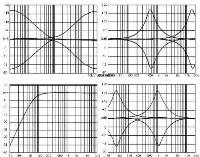
HPF Switches in the channel high pass filter. This attenuates frequencies below 80Hz by 12dB per octave. The filter is pre-insert, pre-EQ. Select the HPF to reduce low frequency noise such as microphone popping, stage noise and tape transport rumble.
EQ A 4-band semi parametric EQ provides independent control of four frequency bands. HF and LF are shelving filters which affect high frequencies above 12kHz, and low frequencies below 80Hz respectively. HM and LM are bell shaped peak/dip filters which affect frequencies around a centre point which can be swept from 500Hz to 15kHz and 35Hz to 1kHz respectively. These have a width (Q) of 1.8. All bands can be boosted or cut by up to 15dB and have a centre detent 0dB position.
Check for the best microphone selection and placement before using the EQ. Start with the EQ set flat and apply only as much boost or cut as is really needed. The EQ IN button can be used to compare the EQ with a flat response. When dealing with problem frequencies cut rather than boost where possible.
line
| Time (s) | Value 1 (dB) | Value 2 (dB) | Value 3 (dB) | Value 4 (dB) | |----------|--------------|--------------|--------------|--------------| | 0 | -25 | 0 | 0 | 0 | | 10 | -15 | 0 | 0 | 0 | | 20 | -5 | 0 | 0 | 0 | | 30 | 0 | 0 | 0 | 0 | | 40 | 5 | 0 | 0 | 0 | | 50 | 10 | 0 | 0 | 0 | | 60 | 15 | 0 | 0 | 0 | | 70 | 18 | 0 | 0 | 0 | | 80 | 15 | 0 | 0 | 0 | | 90 | 12 | 0 | 0 | 0 | | 100 | 10 | 0 | 0 | 0 | | 110 | 8 | 0 | 0 | 0 | | 120 | 6 | 0 | 0 | 0 | | 130 | 4 | 0 | 0 | 0 | | 140 | 2 | 0 | 0 | 0 | | 150 | 0 | 0 | 0 | 0 | | 160 | -2 | 0 | 0 | 0 | | 170 | -4 | 0 | 0 | 0 | | 180 | -6 | 0 | 0 | 0 | | 190 | -8 | 0 | 0 | 0 | | 200 | -10 | 0 | 0 | 0 | | 210 | -12 | 0 | 0 | 0 | | 220 | -14 | 0 | 0 | 0 | | 230 | -16 | 0 | 0 | 0 | | 240 | -18 | 0 | 0 | 0 | | 250 | -20 | 0 | 0 | 0 | | 260 | -22 | 0 | 0 | 0 | | 270 | -24 | 0 | 0 | 0 | | 280 | -26 | 0 | 0 | 0 | | 290 | -28 | 0 | 0 | 0 | | 300 | -30 | 0 | 0 | 0 | | ... | ... | ... | ... | ... | | ... | ... | ... | ... | ... | | ... | ... | ... | ... | ... | | ... | ... | ... | ... | ... | | ... | ... | ... | ... | ... | | ... | ... | ... | ... | ... | | ... | ... | ... | ... | ... | | ... (approx) | ... | ... | ... | ... | | Note: The actual values for the 'Value' series are not provided in the code. The 'Time' values are marked as '1', so they are not explicitly labeled in the image. The 'Frequency' values are not explicitly labeled in the image. There is no label for the data series. The 'Time' values are estimated based on the plot area.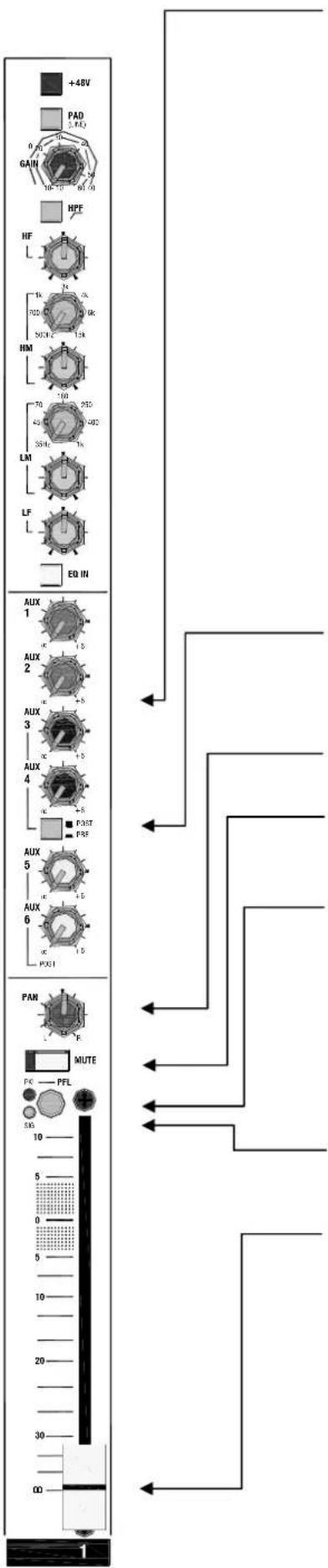
AUX SENDS These rotary controls adjust how much channel signal is mixed to the aux outputs. Each of the 6 auxes has its own control. They adjust from fully off to +6dB boost. Unity gain 0dB is marked at 3 o'clock position. Factory default settings should satisfy the most common applications:
$$ \text { AUX1, AUX2 } = \text { Pre - fade } $$
$$ \text { AUX3, AUX4 } = \text { Switched pre / post using PRE switch } $$
$$ \text { AUX5, AUX6 } = \text { Post - fade } $$
Pre-fade aux options: Pre-INSERT, pre-EQ, post-MUTE
These settings may be changed if preferred by repositioning internal jumper link / solder link options. They offer many different combinations of pre and post-fade sends, and a post-EQ option for the pre-fade sends. The PRE switch can be assigned to one, two or more of the sends. More detail is provided in OPTIONS later in this guide.
Pre-fade aux sends are not affected by the channel fader movements. These are typically used to feed stage monitors. In most cases users also prefer that the monitor sends are not affected by inserted processors or the channel EQ. Post-fade aux sends follow the channel faders and are typically used to send a proportion of the channel signal to an effects device such as reverb or delay. Pre or post-fade sends may also be used for special applications such as recording, zone feeds, clean feeds and aux fed subs.
PRE When pressed the pre-fade channel signal is sent to the associated auxes. When released the post-fade signal is sent. Auxes 3 and 4 are affected by the PRE switch (factory default). You can change this to dedicated pre-fade using the internal options.
PAN Positions the channel signal between L and R in the stereo mix. The centre position (mono image) is detented for quick resetting.
MUTE When pressed the channel signal is turned off. This affects the feed to the LR mix, pre and post-fade aux sends and direct output, but does not affect the insert send. The red indicator lights when the channel is muted.
PFL Press PFL to listen to the pre-fade channel signal in the headphones or AB monitor (if configured) without affecting the main outputs. The console main LR meters are interrupted with the channel signal. The red PK indicator half lights to show that PFL has been selected on that channel. Selecting more than one PFL at the same time mixes those signals together in the monitor.
PEAK The red indicator illuminates when the channel pre-fade signal is within 5dB of clipping. This gives you enough warning to reduce the GAIN control before you hear signal distortion.
SIGNAL The green signal presence indicator lights when the channel pre-fade signal is greater than -12dBu.
FADER Controls the channel level feeding the main LR mix and post-fade aux sends. It also affects the direct output if this has been set to post-fade using the internal option jumper. The fader provides +10dB maximum boost above its normal unity gain 0dB position.
Important note on setting channel levels: Use PFL to set the GAIN controls for correct signal level through each channel. Use the faders to balance each signal in the mix. These are typically operated around their -20 to 0 positions according to the mix. We do not recommend setting the faders to '0' and mixing using the GAIN controls.

text_image
GAIN ON S11 9-10 STI-5ST/TO GAIN ON S12 HF L HM L LM L LF L EQ IN AUX 1 00 +4 AUX 2 00 +4 AUX 3 00 +4 AUX 4 00 +4 AUX 5 00 +4 AUX 6 00 +4 PCST BAL MUTE PCL PFL S6 10 5 0 5 10 20 30 00 9-10
flowchart
graph TD
    A["Start"] --> B{Decision}
    B -->|Yes| C["Path 1"]
    B -->|No| D["Path 2"]
    C --> E["End"]
    D --> F["End"]
Dual stereo inputs Each of the two stereo channels has two stereo inputs which can be used separately, mixed together or split so that one feeds the channel, the other routes direct to LR. For example, you could mix two sound effects playback devices or two reverb returns together into one channel. This can be useful in saving channels, letting you mix many inputs in a small space. The L input signal normals through the R input socket so that a mono source may be plugged in to feed both left and right sides of the stereo channel.
STI (ST3) Unbalanced TRS inputs. The GAIN control adjusts from fully off to +16dB gain. Press the STI (ST3) switch to turn the input on.
Routing mode switch Recessed switch to prevent accidental operation. In the normal up position the ST1 (ST3) signal mixes with ST2 (ST4) into the stereo channel. When pressed the signal is routed direct to the LR mix instead of the channel. This lets you use these inputs as simple stereo returns in addition to the full stereo channels, providing four independent stereo sources to the LR mix.
ST2 (ST4) Balanced TRS inputs. The GAIN control adjusts from fully off to +16dB gain. Press the ST2 (ST4) switch to turn the input on. These inputs always feed the stereo channels.
EQ A 4-band fixed frequency EQ provides independent control of four frequency bands. HF and LF are shelving filters which affect high frequencies above 12kHz, and low frequencies below 80Hz respectively. HM and LM are bell shaped peak/dip filters which affect frequencies centred around 2.5kHz and 250Hz respectively. These have a width (Q) of 1.8. All bands can be boosted or cut by up to 15dB and have a centre detented 0dB position.
AUX SENDS These work as described for the mono channel. The L and R sides of the stereo signal sum together to feed each aux in mono. This can be changed using an internal solder option so that L feeds auxes 1,3 and R feeds auxes 2,4.
BAL Balances the level of the L signal against the R signal to compensate for differences in the source signal, or to position the signal within the stereo image. The centre equal level position is detented for quick resetting.
MUTE When pressed the channel signal is turned off. This affects the feed to the LR mix, and pre and post-fade aux sends. The red indicator lights when the channel is muted.
PFL Press PFL to listen to the summed L+R pre-fade channel signal in the headphones or AB monitor (if configured) without affecting the main outputs. The console main LR meters are interrupted with the channel signal. The red PK indicator half lights to show that PFL has been selected on that channel.
PEAK The red indicator illuminates when the channel pre-fade signal is within 5dB of clipping. This gives you enough warning to reduce the GAIN control before you hear signal distortion.
SIGNAL The green signal presence indicator lights when the channel pre-fade signal is greater than -12dBu.
FADER Controls the channel level feeding the main LR mix and post-fade aux sends. It also affects the direct output if this has been set to post-fade using the internal option jumper. The fader provides +10dB maximum boost above its normal unity gain 0dB position.
text_image
FX -- Oil Aux sand Delay1 [tap] [regen] 2 DelayLF [tap] [LFregen] 3 DelayHF [tap] [rognn] PlingPong4 [tap] [regen] BeatDelay5 [tap] [regen] 6 StapDelay [time] 7 Ambient [size] 8 EchoVerb [reverb] 9 EchoSpace [size] 10 Doubler [thickness] 11 Plate [decay] 12 PlateDly [predly] 13 PlateEQ [colour] 14 Hall1 [size] 15 Hall2 [size] 16 ConcertHall [size] Arena17 [size] SmallSpace18 [size] 19 Flanger [intensity] 20 Chorus [depth] AUX 1 00 +6 AUX 2 00 +6 AUX 3 00 +6 AUX 4 00 +6 8.8 AUX5 AUX6 Press FX Parameter Hold TAP ST5 / FX LEV 00 +6 FX MUTE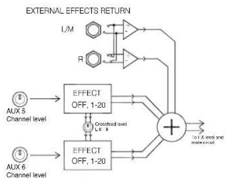
flowchart
graph TD
    A["AUX 5 Channel level"] --> B["EFFECT OFF, 1-20"]
    C["AUX 6 Channel level"] --> D["EFFECT OFF, 1-20"]
    B --> E["+"]
    D --> E
    E --> F["To X level and multiple circuit"]
    G["L/M"] --> H["Amplifier"]
    I["R"] --> J["Amplifier"]
    H --> K["Output"]
    J --> K
    style A fill:#f9f,stroke:#333
    style C fill:#f9f,stroke:#333
    style G fill:#ccf,stroke:#333
    style I fill:#ccf,stroke:#333
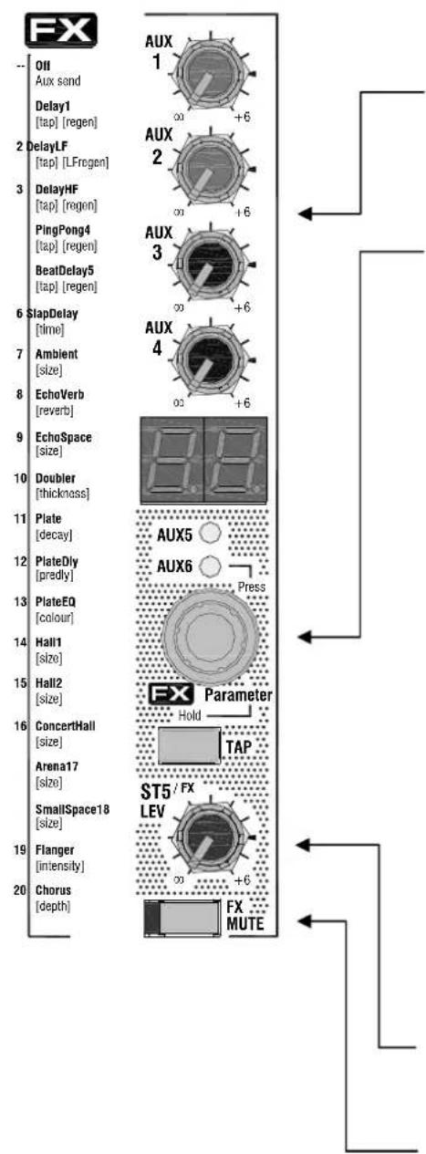
The MixWizard WZ ^4 16:2 and WZ ^4 12:2 feature a built-in stereo digital effects processor. The processed signal is routed back to the mix through the STI (ST5) stereo return channel. The two stereo effects mix together into the return channel. The STI (ST5) TRS jack inputs mix with the internal effects processor through the return channel. This allows you to have the internal and external effects devices returning their processed signals through one return channel.
AUX SENDS The combined effects signal can be returned to Auxes 1 to 4. These sends are not affected by the STI (ST5) LEV control which returns the signal to the LR mix. The stereo signal is summed to feed the auxes in mono. This can be changed if preferred by repositioning internal jumper options so that L feeds auxes 1,3, and R feeds auxes 2,4. Use the aux sends to add the effects to the monitors if required.
Selecting the effect Use the soft touch effects wheel to scroll through all 20 effects. Press and release the effects wheel to toggle between the two effects channels on Aux 5 and Aux 6. The effect names and adjustable parameter are printed on the front panel for reference.
Changing effects parameters Preset parameters can be edited by holding down the tap button and turning the effects wheel (value P0 to 9). The parameter to be changed for each effect is listed below the effect name in square brackets.
Tap effects Effects that include a tap parameter will have a flashing decimal point on the right hand side of the display. Tapping the button will change the tempo shown. Tap effects are marked with [tap] on the effects list on the front of the mixer.
Turning off the internal effects Once you have scrolled through all 20 effects the display will show a line to indicate that the effects on this channel are switched off.
Dual Effects Crossfeed The effects channels can be combined to allow one effect to feed another which gives more control over interaction between effects.
The effects on Aux 5 can be fed into the Aux 6 effects by holding down the tap button and the effects wheel while turning the wheel to select the amount mixed in. The value L0 to 9 indicates the amount of effect mixed between channels. The left hand decimal point comes on to show that this feature is being used. The AUX5 channel pot now controls this dual effect. The effect is sent through the AUX5 effects processor and then through the AUX6 effects processor. The feeds are mixed in parallel as shown in the diagram opposite. The AUX6 channel pot continues to control the amount of the selected channel sent to only the AUX6 effects processor.
STI (ST5) LEV Returns the combined stereo effects to the main LR mix. Adjust from fully off to +6dB maximum boost. Normal 3 0'clock 0dB operating position is marked on the panel.
FX MUTE Press this switch to mute the stereo return channel. This turns off the effects feed to the LR mix and auxes 1-4. The channel may also be muted using a footswitch plugged into the rear of the console. The red indicator lights when the channel is muted by the MUTE switch and/or the footswitch. Note that the MUTE switch is latching. This means the effects will remain muted as long as the switch is in its pressed position regardless of the footswitch.
Resetting the effects presets To restore the factory default presets hold down the TAP key and the effects wheel while powering up the console. Make sure you do this while the amplifiers are turned off. The display will flash some scrolling lines to confirm the reset.
text_image
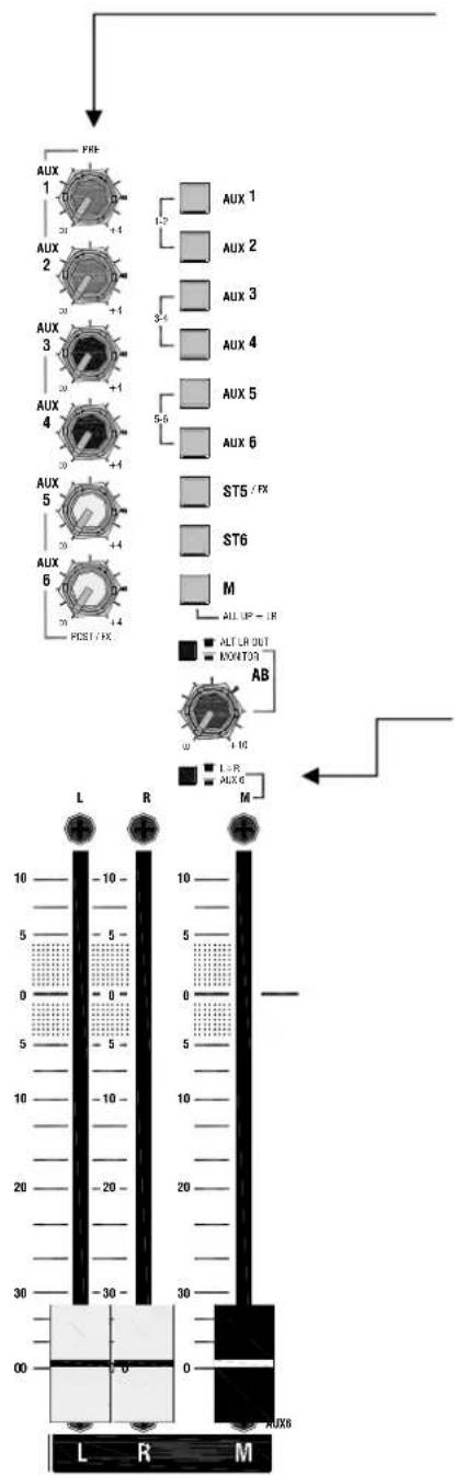
AUX 1 2 3 4 5 6 FREF AUX 1 AUX 2 AUX 3 AUX 4 AUX 5 AUX 6 ST5 / FX ST6 M ALL UP - IN ALT LR OUT MONT39 AB L R M 00 0 0 L R M AUX8AUX MASTERS Each aux mix has a master level control that adjusts the output level to match external equipment, or to trim the monitor, effect or other send without affecting the mix balance. Up to +4dB boost is available above the normal 0dB position.
Note that the AUX5 and AUX6 master controls do not affect the level sent to the internal effects processor. They do affect the level available at the rear panel aux output sockets.
LR FADER MASTERS Individual faders adjust the main L-R mix level. They provide +10dB boost above the nominal '0' position. For best performance the faders should be operated around the '0' position for normal 'loud' level. If you find yourself operating significantly below '0' then the amplifier or other destination equipment is too sensitive for the console +4dBu output. Simply turn down the amplifier or equipment level trim. If none is available then insert an attenuator pad between the console and connected equipment. Operating the faders well below '0' may degrade the noise performance of the equipment.
M FADER MASTER A recessed mode switch above the M fader selects the fader source.
Mono master To use the M output as an L+R summed mono feed then select the up position. The fader can become the master level controller for a mono PA, mono fill or delay speaker, additional zone, mono recording and so on.
Aux master To use the M output as the AUX6 master press the switch using a pen or pointed object. Use the post-fade AUX6 channel sends to mix the required signals to the M output. This provides a main console output with its own mix bus. Typical applications include:
Dedicated MONO mix The output feeds a centre mono fill speaker system, for example above the proscenium arch or along the front of the stage in a theatre. You may wish to feed just a few of the sources to these speakers, for example just the radio mic channels for front row clarity. Using the aux send allows you to create the required mix balance and have proper master fader control.
Aux fed subs This increasingly popular application drives the sub bass speakers with their own mix. It lets you send only those sources with wanted low frequency information to the sub speakers. It can dramatically clean up the mix as non-bass channels such as vocals and guitars are kept out of the subs and therefore do not allow low frequency pickup to muddy the mix. It is typical to include only sources such as kick drum, bass guitar, keyboards and sound effects to these speakers.
The unique MixWizard aux mode feature puts the master control of the sub mix on to a fader next to the main LR faders. This means that the house volume can be controlled without upsetting the balance between LR and sub speakers. The feed to the sub speaker system is on balanced XLR, and it can be monitored by selecting the M switch in the headphones monitor section.
flowchart
graph TD
    A["ST6/USB LEV"] --> B["TO LR"]
    B --> C["L"]
    B --> D["R"]
    C --> E["PFL"]
    D --> F["POWER"]
    E --> G["AUX 1"]
    E --> H["AUX 2"]
    E --> I["AUX 3"]
    E --> J["AUX 4"]
    E --> K["AUX 5"]
    E --> L["AUX 6"]
    E --> M["ST5 /FX"]
    E --> N["ST6"]
    E --> O["M"]
    O --> P["ALL UP = LR"]
    P --> Q["ALT LR OUT"]
    P --> R["MONITOR"]
    Q --> S["AB"]
    R --> S
    S --> T["+10"]
    T --> U["+10"]
    U --> V["1-2"]
    V --> W["AUX 1"]
    V --> X["AUX 2"]
    V --> Y["AUX 3"]
    V --> Z["AUX 4"]
    V --> AA["AUX 5"]
    V --> AB["AUX 6"]
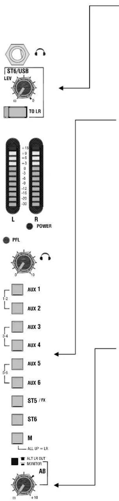
ST2 (ST6) RETURN This is a simple stereo return channel that routes to the main LR mix. The typical application is to plug in a CD or similar playback device for walk-in or background music. It can also be used as an additional effects return. Adjust the volume using the LEV control. Route the signal to LR by pressing the TO LR switch. The green LED lights to warn that the source is routed to LR.
You can use the ST2 (ST6) input to monitor your 2-track recording. Press the ST2 (ST6) monitor source select switch. Use the AB output to feed your recorder. If you are monitoring while mixing live, make sure you do not accidentally press the TO LR switch and route your recording to the house speakers.
Console Monitor Comprehensive engineer's headphones monitoring is provided. Select the source to listen to using the monitor switch bank. With no switch pressed the post-fade LR mix is monitored. Press M to listen to the post-fade M source. Pressing any switch higher up the bank overrides the previous selection. Pressing STI (ST5) listens to the wet effects only return signal if the internal effects processor is active. Pressing Aux pairs 1-2, 3-4, 5-6 together listens to the two selected auxes as a stereo pair. The two console meters display the selected monitor source signal level.
Pressing channel PFL switches automatically overrides the current monitor selection with the pre-fade signal from that channel or selection of channels. The red PFL active indicator lights and the console meters display the channel signal.
We recommend you use closed ear headphones in the range 30 to 600 ohms designed for live sound monitoring. Headphones around 100 ohms impedance are a popular choice.

WARNING: To avoid damage to your hearing do not oper- y close-to-ear monitoring such as headphones for long peri- high volume. Continued exposure to high volume sound can frequency selective or wide range hearing loss.
AB OUTPUT This is an additional stereo output that can be configured as a separately controlled mix output or a local loudspeaker monitor send. A recessed mode switch above the AB level control selects the source. Use a pen or pointed object to change the setting. Adjust the output level from fully off to a maximum +10dB boost. The normal 0dB position is marked on the panel.
With the mode switch in its up position, the LR mix is selected as the source to the AB output TRS jacks. Factory default setting is post-LR fader. If preferred you can change this to pre-LR fader by repositioning internal option jumpers so that the LR master fader movements do not affect the output. In LR mode the AB output provides an additional main mix output ideal for independent fill speaker control, 2-track recording or broadcast feed and so on.
With the mode switch pressed, the console monitor system is selected as the source. You can use this to feed local monitor speakers to listen to the source selected on the monitor switch bank interrupted by PFL. Local speaker monitoring can be useful in theatre and stage monitoring applications.
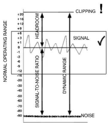
How the levels between the different signal stages are set up is referred to as the gain structure. For best performance it is important that the connected source signals are matched to the 'normal operating level' of the console. Similarly the levels of the connected amplifiers and destination equipment should be correctly matched to the console outputs. If set too high then the signal peaks will be clipped resulting in distortion, and if set too low then the signal-to-noise performance will be degraded resulting in excessive background hiss and noise.
Using the Meters The MixWizard provides metering of inputs and outputs. For best results operate the console with the main meters averaging around '0' allowing the loudest moments to reach '+6'. Reduce the channel gain settings if the red peak indicators start to flash. Note that the peak indicators light 5dB before actual clipping to warn that you are nearing distortion and should reduce gain. The LED bar meters have a 'quasi-peak' response with fast attack and slow release so that fast musical transients are accurately displayed.
Matching a Source to the Console Start by turning down the channel fader and send levels to prevent unexpected loud volumes reaching the main speakers and monitors. Using PFL, adjust the GAIN control for an average '0' reading on the console meters. These automatically switch to show the channel pre-fade signal when PFL is pressed. Listen to the signal using headphones or local AB monitor. Once the channel gain is correctly set you can raise the levels to bring the channel into the mix. Note that you may need to adjust the gain if you make significant changes to the EQ. Make sure that any equipment inserted into the channel is set to operate around 0dBu line level. First set the gain with inserted signal processors such as compressors switched to bypass.
Matching the Console to Destination Equipment The console produces a standard XLR output level of +4dBu for a meter reading of '0'. It can produce a maximum of +26dBu which is more than is usually required and therefore gives you plenty of headroom. If you are connecting to a sensitive power amplifier it is advisable to turn down its input trim control if the normal console level is too high. Simply turning down the console output faders degrades the output stage noise performance and reduces the resolution of the fader movement. The output faders are best operated around '-10' to '0' for loudest average volume required. This allows additional headroom if you need it.
Terminology The normal operating level is the optimum signal level for best console performance, indicated by '0' meter readings and resulting in the +4dBu XLR output level. The channels operate at 0dBu and the mix stages at -2dBu for extended headroom. Headroom is the extra level available above normal to allow for loud peaks before the signal becomes clipped resulting in audible distortion. The signal-to-noise ratio (SNR) is the difference measured in dB between normal level and residual noise floor (hiss) produced by the console electronics. The dynamic range is the sum of headroom and SNR representing the maximum signal range possible from quietest to loudest.
Final word... A little care with setting gain structure throughout the signal chain will give you the best performance and most manageable control of the mix.
line
| Signal Type | Value | | ----------------- | ----- | | CLIPPING | +20 | | SIGNAL | 0 | | SIGNAL-TO-NOISE | -3 | | DYNAMIC RANGE | -12 | | NOISE | -90 |Performance
Maximum output level XLR +26dBu into 600 ohms max load Jack +21dBu into 2k ohm max load
Internal headroom Channels +21dB Mix +23dB
Meters 3 colour LED, quasi peak response
Sensitivity 0VU = +4dBu at XLR output
Master meters 12 segment -30 to +16dB
Channel meters 2 segment -12, +16dB (5dB before clip)
Frequency response 10Hz to 30kHz +/-0.5dB
THD+n at +10dBu 1kHz Channel to mix out < 0.004%
Crosstalk at 1kHz Fader shutoff >90dB
Channel mute >90dB
Inter channel >90dB
Noise, rms 22Hz to 22kHz Mic EIN -127dB
Residual output noise < -95dBu (-99dB S/N)
LR unity fader mix noise < -83dBu (-87dB S/N)
Channel HPF 12dB/octave below 80Hz
Mono EQ HF Shelving, +/-15dB, 12kHz
HM Peak/dip, +/-15dB, 500Hz to 15kHz, Q=1.8
LM Peak/dip, +/-15dB, 35Hz to 1kHz, Q=1.8
LF Shelving, +/-15dB, 80Hz
Stereo EQ HF Shelving, +/-15dB, 12kHz
HM Peak/dip, +/-15dB, 2.5kHz, Q=1.8
LM Peak/dip, +/-15dB, 250Hz, Q=1.8
LF Shelving, +/-15dB, 80Hz
Power supply 100-240V, 50/60Hz auto sensing, IEC input
Power consumption 45W max
Mains fuse T630mA L 20mm
Mechanical
Free standing dimensions W 507 (20") x D 530 (20.9") x H 194 (7.7")
Rack mounted W 483 (19") × D 122 (4.8") × H 444 (17.5") 10U
Underside connectors
Rack mounted W 483 (19") × D 193 (7.6") × H 497 (19.6") 11.2U
Rear connectors
Weight W4-122 unpacked 11kg (24lbs)
W4-122 packed 14kg (31lbs)
W4-162 unpacked 13kg (28lbs)
W4-162 packed 16kg (35lbs)
Connections
Mono channel XLR balanced pin 2 hot Sensitivity -60 to +10dBu
TRS balanced, tip hot Sensitivity -40 to +10dBu
Pad out (MIC) 2k ohm
Pad in (MIC or LINE) >10k ohm, -20dB
Max input level +30dBu
XLR phantom power +48V, on/off
Stereo channel STI,3 TRS unbalanced >10k ohm, -16 to +20dBu
ST2,4 TRS balanced >10k ohm, -16 to +20dBu
Stereo returns STI(5) TRS balanced >10k ohm, -6 to +20dBu
ST2(6) TRS unbalanced >2k ohm, -2 to +20dBu
Inserts Channel TRS, tip send, ring return, 0dBu
Output TRS, tip send, ring return, -2dBu
L, R, M outputs XLR balanced pin 2 hot <75 ohm, +4dBu, +26dBu max
Aux I-6 output TRS impedance balanced <75 ohm, -2dBu, +21dBu max
Electronic balance option <75 ohm, +4dBu, +26dBu max
Direct out TRS impedance balanced <75 ohm, 0dBu, +21dBu max
AB out TRS impedance balanced <75 ohm, -2dBu, +21dBu max
Headphones TRS, tip L, ring R, 30 to 600 ohm headphones recommended
Lamp 4-pin XLR max 12V 5W lamp
MixWizard 4 Series Part Numbers
WZ ^4 12:2 8 mic/line, 2 dual stereo, LR console W4-122
WZ ^4 16:2 16 mic/line LR console W4-162
WZ ^4 14:4:2 10 mic/line, 2 dual stereo, 4 group console W4-1442
WZ ^4 |2:2,WZ ^4 |6:2 & WZ ^4 |4:4:2 USB2 option kit 004-232JIT
SSM2142P balanced output driver option IC AE0302
DRV134 balanced output driver option IC (alternative to above) AE5725
Allen & Heath 18" gooseneck LED lamp LEDLAMP
flowchart
graph TD
    subgraph Control Modules
        direction TB
        M["Power Supply"] --> A1["AC Source"]
        A1 --> B1["AC Filter"]
        B1 --> C1["AC Control Unit"]
        C1 --> D1["AC Power Supply"]
        D1 --> E1["AC Filter"]
        E1 --> F1["AC Control Unit"]
        F1 --> G1["AC Power Supply"]
        G1 --> H1["AC Control Unit"]
        H1 --> I1["AC Power Supply"]
        I1 --> J1["AC Control Unit"]
        J1 --> K1["AC Power Supply"]
        K1 --> L1["AC Control Unit"]
        L1 --> M1["AC Power Supply"]
        M1 --> N1["AC Control Unit"]
        N1 --> O1["AC Power Supply"]
        O1 --> P1["AC Control Unit"]
        P1 --> Q1["AC Power Supply"]
        Q1 --> R1["AC Control Unit"]
        R1 --> S1["AC Power Supply"]
        S1 --> T1["AC Control Unit"]
        T1 --> U1["AC Power Supply"]
        U1 --> V1["AC Control Unit"]
        V1 --> W1["AC Power Supply"]
        W1 --> X1["AC Control Unit"]
        X1 --> Y1["AC Power Supply"]
        Y1 --> Z1["AC Control Unit"]
        Z1 --> AA1["AC Power Supply"]
        AA1 --> AB1["AC Control Unit"]
        AB1 --> AC1["AC Power Supply"]
        AC1 --> AD1["AC Control Unit"]
        AD1 --> AE1["AC Power Supply"]
        AE1 --> AF1["AC Control Unit"]
        AF1 --> AG1["AC Power Supply"]
        AG1 --> AH1["AC Control Unit"]
        AH1 --> AI1["AC Power Supply"]
        AI1 --> AJ1["AC Control Unit"]
        AJ1 --> AK1["AC Power Supply"]
        AK1 --> AL1["AC Control Unit"]
        AL1 --> AM1["AC Power Supply"]
        AM1 --> AN1["AC Control Unit"]
        AN1 --> AO1["AC Power Supply"]
        AO1 --> AP1["AC Control Unit"]
        AP1 --> AQ1["AC Power Supply"]
        AQ1 --> AR1["AC Control Unit"]
        AR1 --> AS1["AC Power Supply"]
        AS1 --> AT1["AC Control Unit"]
        AT1 --> AU1["AC Power Supply"]
        AU1 --> AV1["AC Control Unit"]
        AV1 --> AW1["AC Power Supply"]
        AW1 --> AX1["AC Control Unit"]
        AX1 --> AY1["AC Power Supply"]
        AY1 --> AZ1["AC Control Unit"]
        AZ1 --> BA1["AC Power Supply"]
        BA1 --> BB1["AC Control Unit"]
        BB1 --> BC1["AC Power Supply"]
        BC1 --> BD1["AC Control Unit"]
        BD1 --> BE1["AC Power Supply"]
        BE1 --> BF1["AC Control Unit"]
        BF1 --> BG1["AC Power Supply"]
        BG1 --> BH1["AC Control Unit"]
        BH1 --> BI1["AC Power Supply"]
        BI1 --> BJ1["AC Control Unit"]
        BJ1 --> BK1["AC Power Supply"]
        BK1 --> BL1["AC Control Unit"]
        BL1 --> BM1["AC Power Supply"]
        BM1 --> BN1["AC Control Unit"]
        BN1 --> BO1["AC Power Supply"]
        BO1 --> BP1["AC Control Unit"]
        BP1 --> BP2["AC Power Supply"]
        BP2 --> BP3["AC Control Unit"]
        BP3 --> BP4["AC Power Supply"]
        BP4 --> BP5["AC Control Unit"]
        BP5 --> BP6["AC Power Supply"]
        BP6 --> BP7["AC Control Unit"]
        BP7 --> BP8["AC Power Supply"]
        BP8 --> BP9["AC Control Unit"]
        BP9 --> BPA["X/A"]
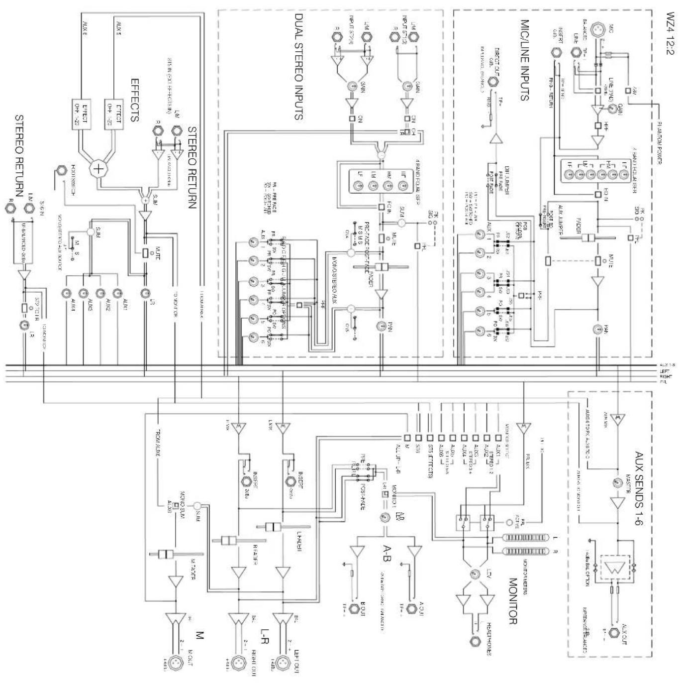
flowchart
graph TD
    subgraph M
        A1["Power Input"] --> B1["Capacitor"]
        B1 --> C1["Resistor"]
        C1 --> D1["Inverter"]
        D1 --> E1["Rectifier"]
        E1 --> F1["Rectifier"]
        F1 --> G1["Rectifier"]
        G1 --> H1["Rectifier"]
        H1 --> I1["Rectifier"]
        I1 --> J1["Rectifier"]
        J1 --> K1["Rectifier"]
        K1 --> L1["Rectifier"]
        L1 --> M1["Rectifier"]
        M1 --> N1["Rectifier"]
        N1 --> O1["Rectifier"]
        O1 --> P1["Rectifier"]
        P1 --> Q1["Rectifier"]
        Q1 --> R1["Rectifier"]
        R1 --> S1["Rectifier"]
        S1 --> T1["Rectifier"]
        T1 --> U1["Rectifier"]
        U1 --> V1["Rectifier"]
        V1 --> W1["Rectifier"]
        W1 --> X1["Rectifier"]
        X1 --> Y1["Rectifier"]
        Y1 --> Z1["Rectifier"]
        Z1 --> AA1["Rectifier"]
        AA1 --> AB1["Rectifier"]
        AB1 --> AC1["Rectifier"]
        AC1 --> AD1["Rectifier"]
        AD1 --> AE1["Rectifier"]
        AE1 --> AF1["Rectifier"]
        AF1 --> AG1["Rectifier"]
        AG1 --> AH1["Rectifier"]
        AH1 --> AI1["Rectifier"]
        AI1 --> AJ1["Rectifier"]
        AJ1 --> AK1["Rectifier"]
        AK1 --> AL1["Rectifier"]
        AL1 --> AM1["Rectifier"]
        AM1 --> AN1["Rectifier"]
        AN1 --> AO1["Rectifier"]
        AO1 --> AP1["Rectifier"]
        AP1 --> AQ1["Rectifier"]
        AQ1 --> AR1["Rectifier"]
        AR1 --> AS1["Rectifier"]
        AS1 --> AT1["Rectifier"]
        AT1 --> AU["Rectifier"]
        AU --> AV["Rectifier"]
        AV --> AW["Rectifier"]
        AW --> AX["Rectifier"]
        AX --> AY["Rectifier"]
        AY --> AZ["Rectifier"]
        AZ --> BA["Rectifier"]
        BA --> BB["Rectifier"]
        BB --> BC["Rectifier"]
        BC --> BD["Rectifier"]
        BD --> BE["Rectifier"]
        BE --> BF["Rectifier"]
        BF --> BG["Rectifier"]
        BG --> BH["Rectifier"]
        BH --> BI["Rectifier"]
        BI --> BJ["Rectifier"]
        BJ --> BK["Rectifier"]
        BK --> BL["Rectifier"]
        BL --> BM["Rectifier"]
        BM --> BN["Rectifier"]
        BN --> BO["Rectifier"]
        BO --> BP["Rectifier"]
        BP --> BQ["Rectifier"]
        BQ --> BR["Rectifier"]
        BR --> BS["Rectifier"]
        BS --> BT["Rectifier"]
        BT --> BU["Rectifier"]
        BU --> BV["Rectifier"]
        BV --> BW["Rectifier"]
        BW --> BX["Rectifier"]
        BX --> BY["Rectifier"]
        BY --> BZ["Rectifier"]
        BZ --> CA["Rectifier"]
        CA --> CB["Rectifier"]
        CB --> CC["Rectifier"]
        CC --> CD["Rectifier"]
        CD --> CE["Rectifier"]
        CE --> CF["Rectifier"]
        CF --> CG["Rectifier"]
        CG --> CH["Rectifier"]
        CH --> CI["Rectifier"]
        CI --> CJ["Rectifier"]
        CJ --> CK["Rectifier"]
        CK --> CL["Rectifier"]
        CL --> CM["Rectifier"]
        CM --> CN["Rectifier"]
        CN --> CO["Rectifier"]
        CO --> CP["Rectifier"]
        CP --> CQ["Rectifier"]
        CQ --> CR["Rectifier"]
        CR --> CS["Rectifier"]
        CS --> CT["Rectifier"]
        CT --> CU["Rectifier"]
        CU --> CV["Rectifier"]
        CV --> CW["Rectifier"]
        CW --> CX["Rectifier"]
        CX --> CY["Rectifier"]
        CY --> CZ["Rectifier"]
        CZ --> DA["Rectifier"]
        DA --> DB["Rectifier"]
        DB --> DC["Rectifier"]
        DC --> DD["Rectifier"]
        DD --> DE["Rectifier"]
        DE --> DF["Rectifier"]
        DF --> DG["Rectifier"]
        DG --> DH["Rectifier"]
    end

    subgraph ESTECTIONS
    EFE0
    EFE2
    EFE4
    EFE6
    EFE8
    EFE0
    EFE2
    EFE4
    EFE6
    EFE8
    EFE0
    EFE2
    EFE4
    EFE6
    EFE8
    EFE0
    EFE2
    EFE4
    EFE6
    EFE8
    EFE0
    EFE2
    EFE4
    EFE6
    EFE0
    EFE2
    EFE4
    EFE6
    EFE8
    EFE0
    EFE2
    EFE4
    EFE6
    EFE8
    EFE0
    EFE2
    EFE4
    EFE6
    EFE8
    EFE0
    EFE2
    EFE4
    EFE6
    EFE6
    EFE8
    EFE0
    EFE2
    EFE4
    EFE6
    EFE8
    EFE0
    EFE2
    EFE4
    EFE6
    EFE8
    EFE0
    EFE2
    EFE4
    EFE6
    EFE8
    EFE0
    EFE2
    EFE2
    EFE4
    EFE6
    EFE8
    EFE0
    EFE2
    EFE4
    EFE6
    EFE8
    EFE0
    EFE2
    EFE4
    EFE6
    EFE8
    EFE0
    EFE2
    EFE4
    EFE6
    EFE8
    EFE6
    EFE0
    EFE2
    EFE4
    EFE6
    EFE8
    EFE0
    EFE2
    EFE4
    EFE6
    EFE8
    EFE0
    EFE2
    EFE4
    EFE6
    EFE8
    EFE0
    EFE2
    EFE4
    EFE2
    EFE4
    EFE6
    EFE8
    EFE0
    A-B & MONTR & MONTR MONTR MONTR MONTR MONTR MONTR MONTR MONTR MONTR MONTR MONTR MONTR MONTR MONTR MONTR MONTR MONTR MONTR MONTR MONTR MONTR MONTR MONTR MONTR MONTR MONTR MONTR MONTR MONTR MONTR MONTR MONTR MONTR MONTR MONTR MONTR MONTR MONTR MONTR MONTR MONTR MONTR MONTR MONTR MONTR MONTR MONTR MONTR MONTR MONTR MONTURMONMMONMMONMMONMMONMMONMMONMMONMMONMMONMMONMMONMMONMMONMMONMMONMMONMMONMMONMMONMMONMMONMMONMMONMMONMMONMMONMMONMMONMMONMMONMMONMMONMMONMMONMMONMMONMMONMMONMMONMMONMMONMMONMMONMMONMMONMMONMMONMMONMMONMMONMTONPMONPMONPMONPMONPMONPMONPMONPMONPMONPMONPMONPMONPMONPMONPMONPMONPMONPMONPMONPMONPMONPMONPMONPMONPMONPMONPMONPMONPMONPMONPMONPMONPMONPMONPMONPMONPMONPMONPMONPMONPMONPMONPMONPMONPMONPMONPMONPMONPMONPMONPOMPNPMONPMPNPMONPMPNPMONPMPNPMONPMPNPMONPMPNPMONPMPNPMONPMPNPMONPMPNPMONPMPNPMONPMPNPMONPMPNPMONPMPNPMONPMPNPMONPMPNPMONPMPNPMONPMPNPMONPMPNPMONPMPNPMONPMPNPMONPMPNPMONPMPNPMONPMPNPMONPMPNPMONPMPNPMONPMPNPMONPOMPNPOMPNPOMPNPOMPNPOMPNPOMPNPOMPNPOMPNPOMPNPOMPNPOMPNPOMPNPOMPNPOMPNPOMPNPOMPNPOMPNPOMPNPOMPNPOMPNPOMPNPOMPNPOMPNPOMPNPOMPNPOMPNPOMPNPOMPNPOMPNPOMPNPOMPNPOMPNPOMPNPOMPNNAMAMAMAMAMAMAMAMAMAMAMAMAMAMAMAMAMAMAMAMAMAMAMAMAMAMAMAMAMAMAMAMAMAMAMAMAMAMAMAMAMAMAMAMAMAMAMAMAMAMAMAMAMAMAMAMAMAMAMAMAMAMAMAMAMAMAMAMAMAMAMAMAMAMAMAMAMAMAMAMAMAMAMAMAMAMAMAMAMAMAMAMAMAMAMAMAMAMAMAMAUMAUMAUMAUMAUMAUMAUMAUMAUMAUMAUMAUMAUMAUMAUMAUMAUMAUMAUMAUMAUMAUMAUMAUMAUMAUMAUMAUMAUMAUMAUMAUMAUMAUMAUMAUMAUMAUMAUMAUMAUMAUMAUMAUMAUMAUMAUMAUMAUMAUMAULUUMUUMUUMUUMUUMUUMUUMUUMUUMUUMUUMUUMUUMUUMUUMUUMUUMUUMUUMUUMUUMUUMUUMUUMUUMUUMUUMUUMUUMUUMUUMUUMUUMUUMUUMUUMUUMUUMUUMUUMUUMUUMUUMUUMUUMUUMUUMUUMUUMUUMUUNHUNHUNHUNHUNHUNHUNHUNHUNHUNHUNHUNHUNHUNHUNHUNHUNHUNHUNHUNHUNHUNHUNHUNHUNHUNHUNHUNHUNHUNHUNHUNHUNHUNHUNHUNHUNHUNHUNHUNHUNHUNHUNHUNHUNHUNHUNHUNHUNHUNHUN HUNHUN HUNHUN HUNHUN HUNHUN HUNHUN HUNHUN HUNHUN HUNHUN HUNHUN HUNHUN HUNHUN HUNHUN HUNH UNHUN HUN HUN HUN HUN HUN HUN HUN HUN HUN HUN HUN HUN HUN HUN HUN HUN HUN HUN HUN HUN HUN HUN HUN HUN HUN HUN HUN HUN HUN HUN HUN HUN HUNDAN POMPTB 35555555555555555555555555555555555555555555555555555555555555555555555555555555555555555555555555555 37777777777777777777777777777777777777777777777777777777777777777777777777777777777777777777777777777 39999999999999999999999999999999999999999999999999999999999999999999999999999999999999999999999999999 300000000000000000000000000000000000000000000000000000000000000000 3888888888888888888888888888888888888888888888888888888888888888888888 38888888888888888888888888888888888 388888888 38888888 3888888 38888 3888 388 38 38 38 38 38 38 38 38 38 38 38 38 3<ecel><nl>
text_image
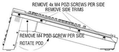
REMOVE 4x M4 POZI SCREWS PER SIDE REMOVE SIDE TRIMS REMOVE M4 POZI SCREW PER SIDE ROTATE POD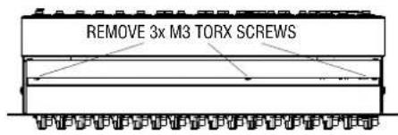
text_image
REMOVE 3x M3 TORX SCREWS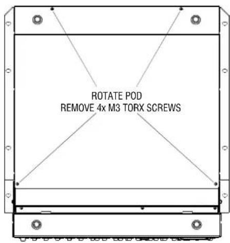
text_image
ROTATE POD REMOVE 4x M3 TORX SCREWS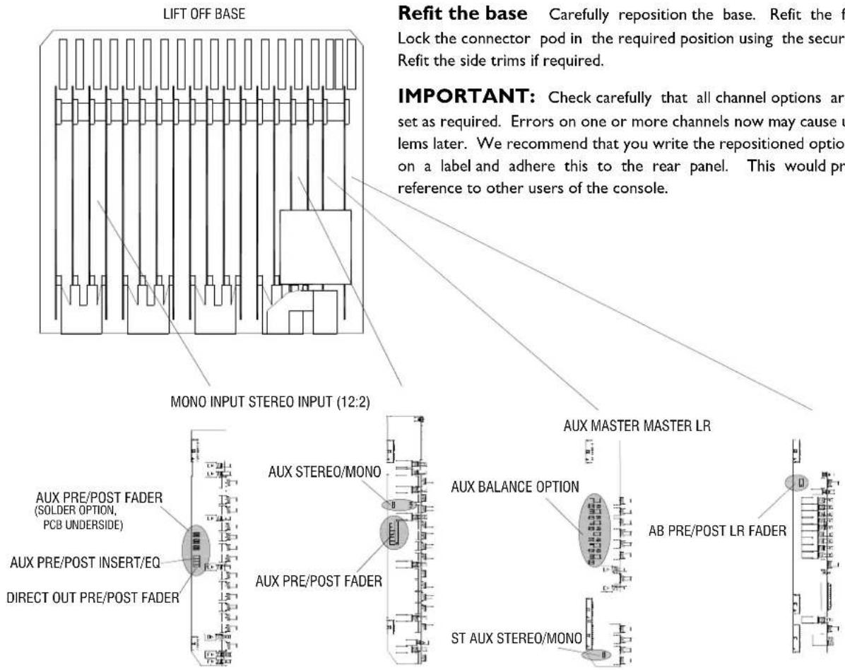
text_image
LIFT OFF BASE MO NO INPUT STEREO INPUT (12:2) AUX PRE/POST FADER (SOLDER OPTION, PCB UNERSIDE) AUX PRE/POST INSERT/EQ DIRECT OUT PRE/POST FADER AUX STEREO/MONO AUX PRE/POST FADER AUX MASTER MASTER LR AUX BALANCE OPTION AB PRE/POST LR FADER ST AUX STEREO/MONO IMPORTANT: Check carefully that all channel options are set as required. Errors on one or more channels now may cause u lems later. We recommend that you write the repositioned option on a label and adhere this to the rear panel. This would pre reference to other users of the console.The MixWizard has a versatile architecture which should satisfy most applications you may encounter without modification. However, the following internal options provide alternative settings for those applications that may demand them. Access is required to the internal assemblies. pluggable jumper links are used in most places and also some links require cutting and soldering a solder bridge.
Remove the base Start by removing the side trims if fitted using a Pozi crosshead screwdriver. Release the two M4 Pozi head pod securing screws and rotate the connector pod to gain access to the three M3 rear base fixing screws. Use a Torx starhead screwdriver to remove these. Rotate the pod again to remove the four M3 underside base screws using the Torx driver. Carefully lift off the base.
Configure the internal options
Jumper Options:
Fit the options required. Set the option jumpers to the required positions. Make sure they are pressed fully home. Check that all channels are correctly set and all options fitted according to their instructions. Make sure that no debris or parts are left loose inside the console.
Solder Options:
Solder options require some ability with a soldering iron, if you have any reservations then please contact your local service centre to carry out this procedure for you.
See page opposite for details on how to modify the solder options.
Refit the base Carefully reposition the base. Refit the fixing screws. Lock the connector pod in the required position using the securing screws. Refit the side trims if required.
IMPORTANT: Check carefully that all channel options are correctly set as required. Errors on one or more channels now may cause user problems later. We recommend that you write the repositioned option settings on a label and adhere this to the rear panel. This would provide a helpful reference to other users of the console.
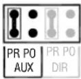
MONO CH - AUX PRE/POST EQ
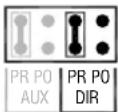
MONO CH - DIRECT OUT
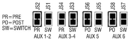
MONO CH - AUX PRE/POST FADER
text_image
PR=PRE PO=POST SW=SWITCH JS2 JS1 JS4 JS3 JS6 JS5 JS8 JS7 PR SW PR SW PO SW PO SW AUX 1-2 AUX 3-4 AUX 5 AUX 6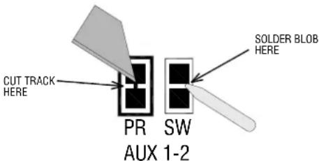
text_image
CUT TRACK HERE PR AUX 1-2 SW SOLDER BLOB HERESTEREO CH - AUX PRE/POST FADER
text_image
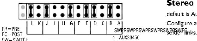
Stereo default is Au Configure as SWPRSWPRSWPRSWPRSWPOSWPO solder links. PR=PRE PO=POST SW=SWITCH 1 AUX23456Aux pre/post insert/EQ Factory default for the mono channel pre-fade auxes is pre-insert, pre-EQ. This is popular with many users mixing monitors from FOH. It prevents the channel EQ and inserted compressors affecting the monitor mix. Move the jumper from PR to PO to change this to post-insert, post-EQ if preferred. Note that auxes are always post-mute.
Direct output source Factory default is pre-fader. This is common for live recording to multitrack. The live mix fader movements do not affect the recording. Move the jumper from PR to PO to change to post-fade. Post-fade is appropriate when using the output as a direct channel effects send.
Mono Channel Aux pre/post settings Factory de-
fault is Aux 1-2 = pre-fade, Aux 3-4 = switched, Aux 5-6 = post-fade. You can change these settings for different combinations of pre/post or switched auxes by cutting and resoldering the links. Refer to the system block diagram to explore the possibilities. Make sure you set all mono and stereo channels the same. Before you make your choice, consider whether you want to use AUX5 or 5/6 for the internal effects (should be post) and/or AUX6 to feed aux fed subs (also post). We recommend you only change these settings if absolutely necessary.
Solder Options: Cut tracks with a sharp knife and ensure that any cuts don't extend beyond the marked area. Add a solder blob to connect the adjoining pads. If you have any doubts about this procedure please contact Allen & Heath and we will put you in touch with your nearest service centre.
Stereo Channel Aux pre/post settings Factory
default is Aux 1&2 = pre-fade, Aux 3&4 = switched, Aux 5&6 = post-fade. Configure as mono channel but connections are using jumpers instead of SODER links.
STEREO CH - MONO/STEREO AUXES
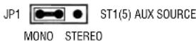
AUX MASTER - ST1(5) MONO/STEREO
LR MASTER - AB SOURCE
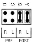
AB PRE/POST LR FADER
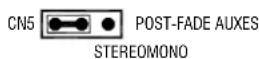
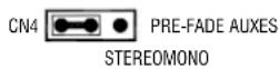
Stereo/Mono aux source The stereo channels can feed the auxes with a mono sum of L+R, or be configured so that L feeds the odd numbered auxes, and R the even. This is preferred when using odd/even auxes as stereo pairs. Factory default is the mono setting. Note that you should also set the STI (ST5) stereo/mono jumper to the same position.
Effects return stereo/mono aux source The return
channel STI (5) feeds Auxes 1-4 with a mono sum of the stereo signal. If you are working with stereo auxes you can reconfigure this for stereo with L feeding Auxes 1, 3 and R feeding Auxes 2, 4.
AB source pre or post LR faders The factory default is that the post-fade LR mix feeds the AB output. If you prefer the master LR faders not to affect the AB output then reposition the two option jumpers in the PRE position. This may be desired if you are using the AB output to feed a 2-track recording independent of the house level.
text_image
AUX MASTER - BALANCED OUTPUT OPTION U12 U11 U10 U9 U8 U7 AUX6 AUX5 AUX4 AUX3 AUX2 AUX1 CUT OUT TWO RESISTOR LINKS INSERT DRIVER ICWZ ^4 12:2
text_image
USB 2.0 MULTICHANNEL AUDIO SENDS 15/16 ST6 SOURCE ■ LR INSERTS ■ AB ■ ST6 INPUT ■ USB RETURNWZ ^4 16:2
text_image
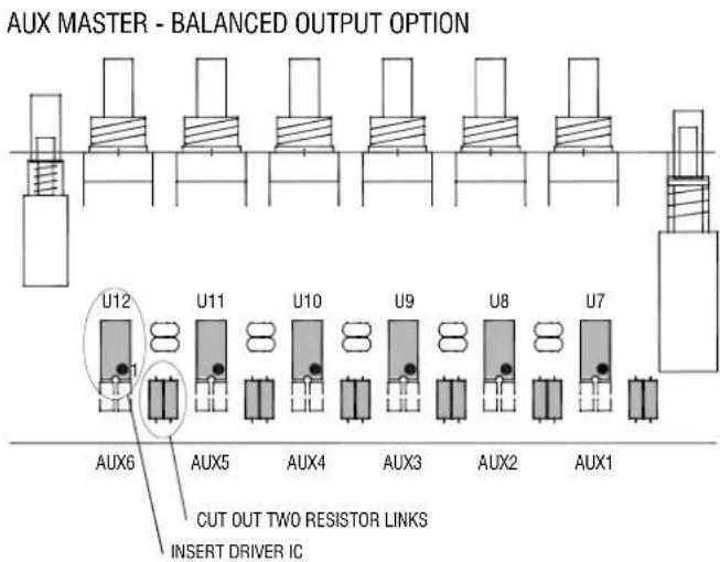
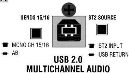
SENDS 15/16 ST2 SOURCE ■ MONO CH 15/16 ■ AB ■ ST2 INPUT ■ USB RETURN USB 2.0 MULTICHANNEL AUDIOAUX master balance option The 6 aux outputs are impedance balanced as standard operating at nominal -2dBu and with +21dBu maximum drive. They provide similar interference rejection to electronically balanced outputs when connected to balanced equipment inputs. An electronically balanced option is available if you require nominal +4dBu and higher output drive up to +26dBu over very long cable runs. However, it is not usually necessary to fit this option as the impedance balanced drive satisfies most applications. Check that you really need the option before fitting it.
There are two balanced driver ICs which may be used. Either is suitable. These are available from Allen & Heath or most electronic component suppliers. The Allen & Heath part number is shown below:
SSM2142 A&H Part AE0302
DRV134 A&H Part AE5725
For each aux master, snip the legs of the two zero ohm resistor links as shown. This removes them from the circuit. Now solder the option IC into the socket. Observe the correct IC pin I orientation and make sure its legs are correctly aligned with the socket. Test the output once the work is complete. You should measure the same level but opposite polarity signal between + (hot) and ground, and - (cold) and ground.
NOTE: This procedure will require the use of a soldering iron. If you have any doubts please contact Allen & Heath and we will put you in touch with your nearest service centre.
USB OPTION A blanking plate is fitted over the rear USB socket as standard.
A USB multi-channel option card is available, the part number is shown below:
004-232JIT WZ4 USB AUDIO OPTION
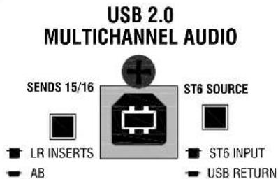
This is a high quality audio card that sends 16 channels from the mixer to a computer for recording or processing. A stereo channel is returned to the mixer for monitoring purposes or as an effects return path.
For the 12:2 the card sends the following channels to the computer: Mono channels I-8 direct out, Aux outputs I-6, Left/right insert sends OR AB outputs.
For the 16:2 the card sends the following: Mono channels 1-14 direct out, Mono channels 15 & 16 direct out OR AB outputs.
The ST2(ST6) source can toggled between the computer return feed or the input sockets mounted at the rear of the mixer.
For full details please refer to the WZ4 USB option application note AP8987 and fitting instructions AP8988.
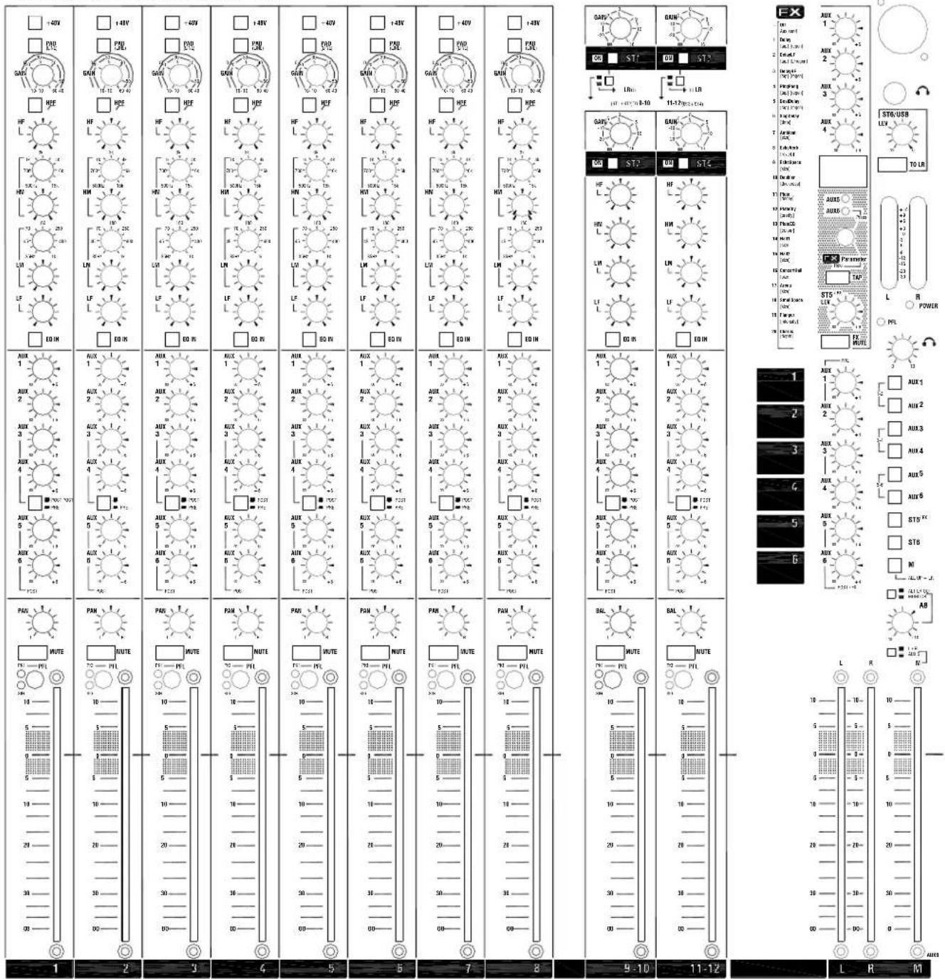
Copy and use this page to record your console settings
ALLEN&HEATH MixWizard WZ 412:2
text_image
1 2 3 4 5 6 7 8 9-10 11-12 L R M AUX 1 AUX 2 AUX 3 AUX 4 AUX 5 AUX 6 AUX 7 AUX 8 AUX 9 AUX 10 AUX 11 AUX 12 AUX 13 AUX 14 AUX 15 AUX 16 AUX 17 AUX 18 AUX 19 AUX 20 AUX 21 AUX 22 AUX 23 AUX 24 AUX 25 AUX 26 AUX 27 AUX 28 AUX 29 AUX 30 AUX 31 AUX 32 AUX 33 AUX 34 AUX 35 AUX 36 AUX 37 AUX 38 AUX 39 AUX 40 AUX 41 AUX 42 AUX 43 AUX 44 AUX 45 AUX 46 AUX 47 AUX 48 AUX 49 AUX 50 AUX 51 AUX 52 AUX 53 AUX 54 AUX 55 AUX 56 AUX 57 AUX 58 AUX 59 AUX 60 AUX 61 AUX 62 AUX 63 AUX 64 AUX 65 AUX 66 AUX 67 AUX 68 AUX 69 AUX 70 AUX 71 AUX 72 AUX 73 AUX 74 AUX 75 AUX 76 AUX 77 AUX 78 AUX 79 AUX 80 AUX 81 AUX 82 AUX 83 AUX 84 AUX 85 AUX 86 AUX 87 AUX 88 AUX 89 AUX 90 AUX 91 AUX 92 AUX 93 AUX 94 AUX 95 AUX 96 AUX 97 AUX 98 AUX 99 AUX10000000000000000000000000000000000000000000000000000000000000000000000000000000000000000000000000000Copy and use this page to record your console settings