
Inspiron XPS - Laptop DELL - Free user manual and instructions
Find the device manual for free Inspiron XPS DELL in PDF.


User questions about Inspiron XPS DELL
0 question about this device. Answer the ones you know or ask your own.
Ask a new question about this device
Download the instructions for your Laptop in PDF format for free! Find your manual Inspiron XPS - DELL and take your electronic device back in hand. On this page are published all the documents necessary for the use of your device. Inspiron XPS by DELL.
USER MANUAL Inspiron XPS DELL
Notes, Notices, and Cautions
NOTE: A NOTE indicates important information that helps you make better use of your computer.
NOTICE: A NOTICE indicates either potential damage to hardware or loss of data and tells you how to avoid the problem.
CAUTION: A CAUTION indicates a potential for property damage, personal injury, or death.
Abbreviations and Acronyms
For a complete list of abbreviations and acronyms, see the Dell ^™ Inspiron ^™ Help file. To access the help file, see page 18.
If you purchased a Dell ^™ n Series computer, any references in this document to Microsoft ^® Windows ^® operating systems are not applicable.
Information in this document is subject to change without notice.
© 2004 Dell Inc. All rights reserved.
Reproduction in any manner whatsoever without the written permission of Dell Inc. is strictly forbidden.
Trademarks used in this text: Dell, the DELL logo, TrueMobile, Dell TravelLite, Inspiron, Dell Precision, Dimension, OptiPlex, Latitude, PowerEdge, PowerVault, PowerConnect, PowerApp, DellNet, Axim, and Dell OpenManage are trademarks of Dell Inc.; Intel, Pentium, and Celeron are registered trademarks of Intel Corporation; Microsoft and Windows are registered trademarks of Microsoft Corporation; Bluetooth is a trademark owned by Bluetooth SIG and is used by Dell Inc. under license; EMC is a registered trademark of EMC Corporation.
Other trademarks and trade names may be used in this document to refer to either the entities claiming the marks and names or their products. Dell Inc. disclaims any proprietary interest in trademarks and trade names other than its own.
Model PP09L
May 2004 P/N M3551 Rev. A02
Contents
CAUTION: Safety Instructions 11
SAFETY: General 11
SAFETY: Power 12
SAFETY: Battery. 12
SAFETY: Air Travel. 12
SAFETY: EMC Instructions 13
When Using Your Computer 13
SAFETY: Ergonomic Computing Habits 14
SAFETY: When Working Inside Your Computer 14
SAFETY: Protecting Against Electrostatic Discharge 14
SAFETY: Battery Disposal 15
Finding Information 17
1 A Tour of Your Computer
Front View. 21
Left Side View 25
Right Side View 26
Back View 27
Bottom View. 31
2 Using Your Computer
Transferring Information to a New Computer 33
Configuring Graphics Cards 34
Settings and Functions 34
Connecting Your Computer to a TV or Audio Device 35
S-Video and Standard Audio. 36
S-Video and S/PDIF Digital Audio 37
Composite Video and Standard Audio 39
Composite Video and S/PDIF Digital Audio 40
Enabling S/PDIF Digital Audio 42
Setting Up the Dolby Headphone. 42
Enabling the Display Settings for a TV 43
Connecting Monitors. 43
Using CDs and DVDs 45
Copying CDs and DVDs. 45
How to Copy a CD or DVD 45
Using Blank CD-Rs, CD-RWs, DVD+Rs, and DVD+RWs 46
Helpful Tips. 46
3 Optimizing Performance
DDR Memory and Processor Front-Side Bus 47
Hyper-Threading. 47
4 Using a Battery
Battery Performance 49
Checking the Battery Charge 50
Dell™ QuickSet Battery Meter 50
Microsoft ^® Windows ^® Power Meter. 50
Charge Gauge 50
Low-Battery Warning 51
Charging the Battery 51
Removing a Battery 52
Installing a Battery 53
Storing a Battery. 53
5 Using the Module Bay
About the Module Bay 55
Removing and Installing Devices While the Computer Is Turned Off ..... 55
Removing and Installing Devices While the Computer Is Running ..... 56
6 Using the Keyboard and Touch Pad
Numeric Keypad 59
Key Combinations 59
System Functions 59
Battery 59
CD or DVD Tray 59
Display Functions 60
Radios (Including Wireless Networking and PC Cards With Bluetooth® Wireless Technology) 60
Power Management 60
Speaker Functions 60
Microsoft ^® Windows ^® Logo Key Functions. 61
Touch Pad 62
Customizing the Touch Pad and Track Stick. 63
Changing the Track Stick Cap 63
7 Setting Up a Home and Office Network
Connecting to a Network Adapter 65
Network Setup Wizard 66
Connecting to a Wireless Local Area Network 66
Determining Your Network Type 66
Connecting to a Wireless Network in Microsoft ^® Windows ^® XP. . . . . 67
Configuring Security Settings (Optional) 70
8 Solving Problems
Using the Dell Diagnostics 75
When to Use the Dell Diagnostics 75
Error Messages 77
Video and Display Problems 79
If the display is blank 79
If the display is difficult to read. 80
If only part of the display is readable. 80
Scanner Problems 81
Hard Drive Problems 81
If you have problems with a hard drive 81
PC Card Problems 82
External Keyboard Problems 82
Power Problems 83
Unexpected Characters 84
Touch Pad or Mouse Problems 84
Printer Problems. 85
E-Mail Problems 86
Modem and Internet Connection Problems 86
Network Problems 87
General Program Problems. 88
A program crashes 88
A program stops responding. 88
A solid blue screen appears 88
Error messages appear 88
CD or DVD Problems 89
If you cannot play a CD, CD-RW, or DVD 89
If you cannot eject the CD, CD-RW, or DVD drive tray 89
If you hear an unfamiliar scraping or grinding sound . . . . . . . . . . 90
Sound and Speaker Problems 90
If you have a problem with integrated speakers. 90
If you have a problem with external speakers. 91
E-Mail, Modem, and Internet Problems 92
Resolving Other Technical Problems 93
Drivers 93
What Is a Driver? 93
Identifying Drivers. 94
Reinstalling Drivers and Utilities 94
Resolving Software and Hardware Incompatibilities 96
Using Microsoft ^® Windows ^® XP System Restore 97
Creating a Restore Point. 97
Restoring the Computer to an Earlier Operating State ..... 97
Undoing the Last System Restore 98
Reinstalling Microsoft ^® Windows ^® XP 98
Before You Begin 98
Reinstalling Windows XP 99
9 Adding and Replacing Parts
Before You Begin 103
Recommended Tools 103
Shutting Down Your Computer 103
Memory 105
Mini PCI Card 108
Hard Drive 111
Returning a Hard Drive to Dell 112
Subwoofer 113
Keyboard 114
PC Card With Bluetooth ^® Wireless Technology 116
Modem 117
Removing the Modem 117
Installing the Modem 118
Keyboard Bracket 118
Fans. 119
Hinge Covers 121
Display 124
Display Latch 127
Video Card 128
Processor Thermal-Cooling Assembly 129
Removing the Processor Thermal-Cooling Assembly 129
Installing the Processor Thermal-Cooling Assembly. 130
Palm Rest 130
Processor Module 132
Removing the Processor Module. 132
Installing the Processor Module 133
Flashing the BIOS 134
Reserve Battery 134
System Board 135
Removing the System Board 135
Installing the System Board 137
Speakers 138
Display Latch Release 139
Pin Assignments for I/O Connectors 140
USB Connector 140
Video Connector 140
S-Video TV-Out Connector. 141
IEEE 1394 Connector. 141
DVI-I Connector. 142
10 Appendix
Specifications.... 143
Using the System Setup Program 149
Overview 149
Viewing the System Setup Screens. 150
System Setup Screens. 150
Commonly Used Options. 150
Enabling the Infrared Sensor 151
Dell Technical Support Policy (U.S. Only) 152
Definition of "Dell-Installed" Software and Peripherals 152
Definition of "Third-Party" Software and Peripherals 152
Contacting Dell 152
Regulatory Notices 170
NOM Information (Mexico Only) 171
Limited Warranties 171
Limited Warranty for Dell-Branded Hardware Products (U.S. Only) 171
Limited Warranty Terms for Dell-Branded Hardware Products (Canada Only). 174
Dell Software and Peripherals (Canada Only)....177
1-Year End-User Manufacturer Guarantee (Latin America and the Caribbean Only) 178
Intel® Warranty Statement for Pentium® and Celeron® Processors Only (U.S. and Canada Only) 180
Index 183

CAUTION: Safety Instructions
Use the following safety guidelines to help ensure your own personal safety and to help protect your computer and working environment from potential damage.
SAFETY: General
- Do not attempt to service the computer yourself unless you are a trained service technician. Always follow installation instructions closely.
- If you use an extension power cable with your AC adapter, ensure that the total ampere rating of the products plugged in to the extension power cable does not exceed the ampere rating of the extension cable.
- Do not push objects into air vents or openings of your computer. Doing so can cause fire or electric shock by shorting out interior components.
- Do not store your computer in a low-airflow environment, such as a carrying case or a closed briefcase, while the computer is turned on. Restricting airflow can damage the computer or cause a fire.
- Keep your computer away from radiators and heat sources. Also, do not block cooling vents. Avoid placing loose papers underneath your computer; do not place your computer in a closed-in wall unit or on a bed, sofa, or rug.
- Place the AC adapter in a ventilated area, such as a desk top or on the floor, when you use it to run the computer or to charge the battery. Do not cover the AC adapter with papers or other items that will reduce cooling; also, do not use the AC adapter inside a carrying case.
- The AC adapter may become hot during normal operation of your computer. Use care when handling the adapter during or immediately after operation.
- Do not allow your portable computer to operate with the base resting directly on exposed skin for extended periods of time. The surface temperature of the base will rise during normal operation (particularly when AC power is present). Allowing sustained contact with exposed skin can cause discomfort or, eventually, a burn.
- Do not use your computer in a wet environment, for example, near a bath tub, sink, or swimming pool or in a wet basement.
- If your computer includes an integrated or optional (PC Card) modem, disconnect the modem cable if an electrical storm is approaching to avoid the remote risk of electric shock from lightning via the telephone line.
- To help avoid the potential hazard of electric shock, do not connect or disconnect any cables or perform maintenance or reconfiguration of this product during an electrical storm. Do not use your computer during an electrical storm unless all cables have been disconnected and the computer is operating on battery power.
- If your computer includes a modem, the cable used with the modem should be manufactured with a minimum wire size of 26 American wire gauge (AWG) and an FCC-compliant RJ-11 modular plug.
- Before you open the memory module cover, fan covers, or Mini PCI card cover on the bottom of your computer, disconnect all cables from their electrical outlets and disconnect the telephone cable.
- If your computer has both a modem RJ-11 connector and a network RJ-45 connector, which look alike, make sure you insert the telephone cable into the RJ-11 connector, not the RJ-45 connector.
- PC Cards may become very warm during normal operation. Use care when removing PC Cards after their continuous operation.
- Before you clean your computer, disconnect the computer from the electrical outlet. Clean your computer with a soft cloth dampened with water. Do not use liquid or aerosol cleaners, which may contain flammable substances.
SAFETY: Power
- Use only the Dell-provided AC adapter approved for use with this computer. Use of another AC adapter may cause a fire or explosion.
- Before you connect the computer to an electrical outlet, check the AC adapter voltage rating to ensure that the required voltage and frequency match the available power source.
- To remove the computer from all power sources, turn the computer off, disconnect the AC adapter from the electrical outlet, and remove any battery installed in the battery bay.
- To help prevent electric shock, plug the AC adapter and device power cables into properly grounded power sources. These power cables may be equipped with 3-prong plugs to provide an earth grounding connection. Do not use adapter plugs or remove the grounding prong from the power cable plug. If you use a power extension cable, use the appropriate type, 2-prong or 3-prong, to mate with the AC adapter power cable.
- Be sure that nothing rests on your AC adapter's power cable and that the cable is not located where it can be tripped over or stepped on.
- If you are using a multiple-outlet power strip, use caution when plugging the AC adapter's power cable into the power strip. Some power strips may allow you to insert the plug incorrectly. Incorrect insertion of the power plug could result in permanent damage to your computer, as well as risk of electric shock and/or fire. Ensure that the ground prong of the power plug is inserted into the mating ground contact of the power strip.
SAFETY: Battery
- Use only Dell™ battery modules that are approved for use with this computer. Use of other types may increase the risk of fire or explosion.
- Do not carry a battery pack in your pocket, purse, or other container where metal objects (such as car keys or paper clips) could short-circuit the battery terminals. The resulting excessive current flow can cause extremely high temperatures and may result in damage to the battery pack or cause fire or burns.
- The battery poses a burn hazard if you handle it improperly. Do not disassemble it. Handle a damaged or leaking battery pack with extreme care. If the battery is damaged, electrolyte may leak from the cells and may cause personal injury.
- Keep the battery away from children.
- Do not store or leave your computer or battery pack near a heat source such as a radiator, fireplace, stove, electric heater, or other heat-generating appliance or otherwise expose it to temperatures in excess of 60^ C ( 140^ F). When heated to excessive temperatures, battery cells could explode or vent, posing a risk of fire.
- Do not dispose of your computer's battery in a fire or with normal household waste. Battery cells may explode. Discard a used battery according to the manufacturer's instructions or contact your local waste disposal agency for disposal instructions. Dispose of a spent or damaged battery promptly.
SAFETY: Air Travel
- Certain Federal Aviation Administration regulations and/or airline-specific restrictions may apply to the operation of your Dell computer while you are on board an aircraft. For example, such regulations/restrictions may prohibit the use of any personal electronic device (PFD) that has the capacity for intentional transmission of radio frequency or other electromagnetic signals while on an aircraft.
- In order to best comply with all such restrictions, if your Dell portable computer is equipped with Dell 'TrueMobile™' or some other wireless communication device, please disable this device before you board the aircraft and follow all instructions provided by airline personnel with regard to such device.
- Additionally, the use of any PED, such as a portable computer, may be prohibited in aircraft during certain critical phases of flight, for example, takeoff and landing. Some airlines may further define the critical flight phase as any time the aircraft is below 3050m (10,000 ft). Please follow the airline's specific instructions as to when the use of a PED is allowed.
SAFETY: EMC Instructions
Use shielded signal cables to ensure that you maintain the appropriate electromagnetic compatibility (EMC) classification for the intended environment. For parallel printers, a cable is available from Dell. If you prefer, you can order a cable from Dell at its worldwide website at www.dell.com.
Static electricity can harm electronic components inside your computer. To prevent static damage, discharge static electricity from your body before you touch any of your computer's electronic components, such as a memory module. You can do so by touching a connector on the back panel.
WARNING: Handling the cord on this product, or cords associated with accessories sold with this product, will expose you to lead, a chemical known to the State of California to cause birth defects or other reproductive harm. Wash your hands after handling the cord.
When Using Your Computer
Observe the following safe-handling guidelines to prevent damage to your computer:
- When setting up the computer for work, place it on a level surface.
- When traveling, do not check the computer as baggage. You can put your computer through an X-ray security machine, but never put your computer through a metal detector. If you have the computer checked by hand, be sure to have a charged battery available in case you are asked to turn on the computer.
- When traveling with the hard drive removed from the computer, wrap the drive in a nonconducting material, such as cloth or paper. If you have the drive checked by hand, be ready to install the drive in the computer. You can put the hard drive through an X-ray security machine, but never put the drive through a metal detector.
- When traveling, do not place the computer in overhead storage compartments where it could slide around. Do not drop your computer or subject it to other mechanical shocks.
- Protect your computer, battery, and hard drive from environmental hazards such as dirt, dust, food, liquids, temperature extremes, and overexposure to sunlight.
- When you move your computer between environments with very different temperature and/or humidity ranges, condensation may form on or within the computer. To avoid damaging the computer, allow sufficient time for the moisture to evaporate before using the computer.

NOTICE: When taking the computer from low-temperature conditions into a warmer environment or from high-temperature conditions into a cooler environment, allow the computer to acclimate to room temperature before turning on power.
- When you disconnect a cable, pull on its connector or on its strain-relief loop, not on the cable itself. As you pull out the connector, keep it evenly aligned to avoid bending any connector pins. Also, before you connect a cable make sure both connectors are correctly oriented and aligned.
- Handle components with care. Hold a component such as a memory module by its edges, not its pins.
-
When preparing to remove a memory module from the system board or disconnect a device from the computer, turn off the computer, disconnect the AC adapter cable, remove any battery installed in the battery bay, and then wait 5 seconds before proceeding to help avoid possible damage to the system board.
-
Clean the display with a soft, clean cloth and water. Apply the water to the cloth; then stroke the cloth across the display in one direction, moving from the top of the display to the bottom. Remove moisture from the display quickly and keep the display dry. Long-term exposure to moisture can damage the display. Do not use a commercial window cleaner to clean your display.
- If your computer gets wet or is damaged, follow the procedures described in your Product Information Guide. If, after following these procedures, you confirm that your computer is not operating properly, contact Dell (see page 152 for the appropriate contact information).
SAFETY: Ergonomic Computing Habits

CAUTION: Improper or prolonged keyboard use may result in injury.

CAUTION: Viewing the display or external monitor screen for extended periods of time may result in eye strain.
For comfort and efficiency, observe the ergonomic guidelines in the Dell™ Inspiron™ Help file when setting up and using your computer. To access the help file, see page 18.
This portable computer is not designed for continuous operation as office equipment. For extended use in an office, it is recommended that you connect an external keyboard.
SAFETY: When Working Inside Your Computer
Before removing or installing a memory module, Mini PCI card, fan, keyboard, display, reserve battery, or PC Card with Bluetooth ^® wireless technology, perform the following steps in the sequence indicated.

NOTICE: The only time you should ever access the inside of your computer is when you are installing a memory module, Mini PCI card, fan, keyboard, display, reserve battery, or PC Card with Bluetooth wireless technology.

NOTICE: Wait 5 seconds after turning off the computer before disconnecting a device or removing a memory module, Mini PCI card, fan, keyboard, display, reserve battery, or PC Card with Bluetooth wireless technology to help prevent possible damage to the system board.
1 Shut down your computer and turn off any attached devices.
2 Disconnect your computer and devices from electrical outlets to reduce the potential for personal injury or shock. Also, disconnect any telephone or telecommunication lines from the computer.
3 Remove the main battery from the battery bay.
4 Ground yourself by touching any connector on the back panel.
5 While you work, periodically touch a connector on the back panel to dissipate any static electricity that might harm internal components.
SAFETY: Protecting Against Electrostatic Discharge
Static electricity can harm electronic components inside your computer. To prevent static damage, discharge static electricity from your body before you touch any of your computer's electronic components, such as a memory module. You can do so by touching any connector on the back panel of the computer.
As you continue to work inside the computer, periodically touch any connector on the back panel of the computer to remove any static charge your body may have accumulated.
You can also take the following steps to prevent damage from electrostatic discharge (FSD):
- When unpacking a static-sensitive component from its shipping carton, do not remove the component from the antistatic packing material until you are ready to install the component. Just before unwrapping the antistatic packaging, be sure to discharge static electricity from your body.
- When transporting a sensitive component, first place it in an antistatic container or packaging.
- Handle all sensitive components in a static-safe area. If possible, use antistatic floor pads and workbench pads.
SAFETY: Battery Disposal

Your computer uses a lithium-ion battery and a coin-cell reserve battery. For instructions about replacing the lithium-ion battery in your computer, see "Removing a Battery" on page 52 and "Installing a Battery" on page 53. The reserve battery is a long-life battery, and it is very possible that you will never need to replace it. However, should you need to replace it, see "Reserve Battery" on page 134 for instructions.
Do not dispose of the battery along with household waste. Contact your local waste disposal agency for the address of the nearest battery deposit site.
Finding Information
What Are You Looking For? Find It Here
• How to access tutorials and other how-to information
• How to get a copy of my invoice
• How to extend my warranty
- How to access Dell Support on my Microsoft ^® Windows ^® desktop (U.S. only)
• Additional documentation, tools, troubleshooting information, and links to online support resources
• A diagnostic program for my computer
- Drivers for my computer
• My computer documentation
• My device documentation
Dell Solution Center

On your Windows desktop
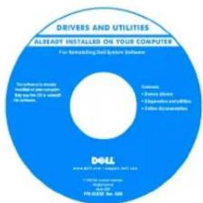
Drivers and Utilities CD (also known as the ResourceCD)
Documentation and drivers are already installed on your computer. You can use the CD to reinstall drivers (see page 94 for instructions), run the Dell Diagnostics (see page 75 for instructions), or access your documentation.
text_image
DRIVERS AND UTILITIES ALREADY INSTALLED ON YOUR COMPUTER For Rebuilding Dell System Software To ensure to install Package or pre-settment. My use is 30-50 seconds to install. Outwards • Deere Block • Expansion Pennsylvania • Offline Accounting DOLL © 2013/10/16 - Occupant Dell Inc. © 2013/10/16 - Product Service PPL 2013E, Ave. 438Readme files may be included on your CD to provide last-minute updates about technical changes to your computer or advanced technical-reference material for technicians or experienced users.
• How to set up a printer
• Additional information about setting up my computer
• How to troubleshoot and solve problems
• How to remove and install parts
- Technical specifications
• How to contact Dell
Owner's Manual
text_image
Dell® Manager® Owner's Manual D&L www.dell.comNOTE: This document is available as a PDF at support.dell.com.
What Are You Looking For? Find It Here
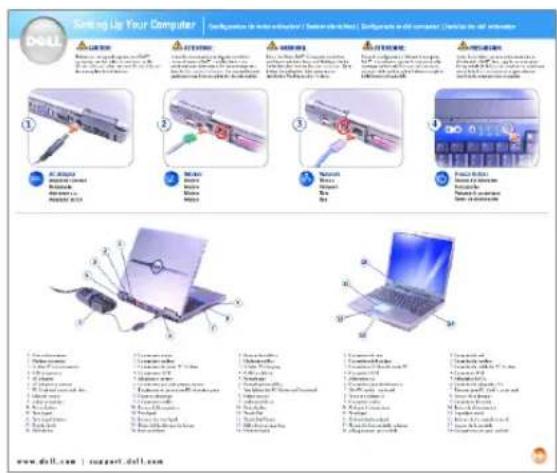
• How to set up my computer
Setup Diagram
text_image
Start Up Your Computer DOLL 1 2 3 4 5 6 7 8 9 10 11 12 13 14 15 16 17 18 19 20 21 22 23 24 25 26 27 28 29 30 31 32 33 34 35 36 37 38 39 40 41 42 43 44 45 46 47 48 49 50 51 52 53 54 55 56 57 58 59 60 61 62 63 64 65 66 67 68 69 70 71 72 73 74 75 76 77 78 79 80 81 82 83 84 85 86 87 88 89 90 91 92 93 94 95 96 97 98 99 100- Tips on using Microsoft ^ Windows ^
• How to play CDs and DVDs
• How to use standby mode and hibernate mode
• How to change my display resolution
• How to clean my computer
• Service Tag and Express Service Code
• Microsoft Windows License Label
Dell Inspiron Help File
1 Click the Start button and click Help and Support.
2 Click User and system guides and click User's guides.
3 Click Dell Inspiron Help.
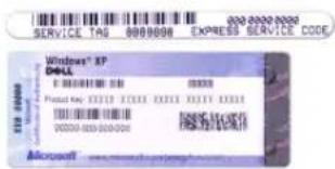
Service Tag and Microsoft Windows License
These labels are located on the bottom of your computer.
- Use the Service Tag to identify your computer when you use support.dell.com or contact technical support.
text_image
SERVICE TAG 88808880 EXPRESS SERVICE CODE Windows® XP DELL Microsoft Windows 1000000 Microsoft 1000000 Microsoft Windows 1000000 Microsoft Windows 1000000 Microsoft Windows 1000000 Microsoft Windows 1000000 Microsoft Windows 1000000 Microsoft Windows 1000000 Microsoft Windows 1000000 Microsoft Windows 1000000 Microsoft Windows 1000000 Microsoft Windows Microsoft Windows 1000000 Microsoft Windows 1000000 Microsoft Windows 1000000 Microsoft Windows 1000000 Microsoft Windows 1000000 Microsoft Windows 1000000 Microsoft Windows 1000000 Microsoft Windows 1000000 Microsoft Windows 1000000- Enter the Express Service Code to direct your call when you contact technical support. The Express Service Code may not be available in certain countries.
- Use the number on the Microsoft Windows License Label if you reinstall your operating system.
| What Are You Looking For? Find It Here | |
| Latest drivers for my computerAnswers to technical service and support questionsOnline discussions with other users and technical supportDocumentation for my computer | Dell Support Website — support.dell.comThe Dell Support website provides several online tools, including:Solutions — Troubleshooting hints and tips, articles from technicians, and online coursesCommunity — Online discussion with other Dell customersUpgrades — Upgrade information for components, such as memory, the hard drive, and the operating systemCustomer Care — Contact information, order status, warranty, and repair informationDownloads — Drivers, patches, and software updatesReference — Computer documentation, product specifications, and white papers |
| How to use Windows XPDocumentation for my computerDocumentation for devices (such as a modem) | Windows Help and Support Center1 Click the Start button and click Help and Support.2 Type a word or phrase that describes your problem and click the arrow icon.3 Click the topic that describes your problem.4 Follow the instructions on the screen. |
| How to reinstall my operating system | Operating System CDThe operating system is already installed on your computer. To reinstall your operating system, use the Operating System CD. For instructions, see "Reinstalling Microsoft Windows XP" on page 98.After you reinstall your operating system, use the Drivers and Utilities CD to reinstall drivers for the devices that came with your computer. For instructions, see "Reinstalling Drivers and Utilities" on page 94.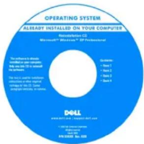 Your operating system product key label is located on your computer. Your operating system product key label is located on your computer. |
A Tour of Your Computer
Front View
text_image
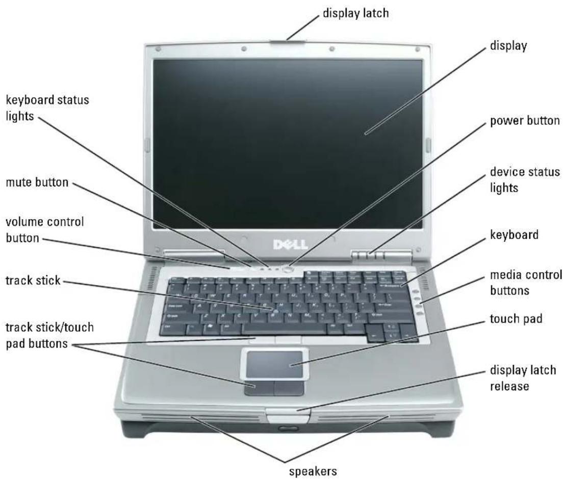
display latch display keyboard status lights power button device status lights mute button volume control button keyboard media control buttons touch pad track stick/touch pad buttons display latch release speakersDISPLAY LATCH — Keeps the display closed.
DISPLAY — For more information about your display, see the Dell Inspiron Help file. To access the help file, see page 18.
POWER BUTTON — Press the power button to turn on the computer or to enter or exit a power management mode.

NOTICE: To avoid losing data when you turn off your computer, shut down your computer through the Start menu instead of pressing the power button.
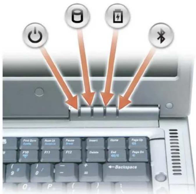
DEVICE STATUS LIGHTS
text_image
Print Screen Zynto Num Lk Num Lk Pause Bryan Insert Home Page Up Q5 F10 F11 F12 Delete End Page On G (9) 0 - + = Backspace
Turns on when you turn on the computer.

Turns on when the computer reads or writes data.


NOTICE: To avoid loss of data, never turn off the computer while the light is flashing.
Turns on steadily or flashes when the computer is in a power management mode. It also flashes to indicate battery charge status.

Turns on when a PC Card with Bluetooth ^® wireless technology is enabled.

NOTE: The PC Card with Bluetooth wireless technology is an optional feature, so the light turns on only if you ordered the card with your computer. For more information, see the Windows Help and Support Center online documentation on PC Cards with Bluetooth wireless technology, or any documentation that came with your device. (To access the Help and Support Center, see page 19.)
To turn off only the functionality of the PC Card with Bluetooth wireless technology, right-click the ⚙ icon in the notification area and select Disable Bluetooth Radio.
To quickly enable or disable all wireless devices, press
If the computer is connected to an electrical outlet, the light operates as follows:
• Solid green: The battery is charging.
- Flashing green: The battery is almost fully charged.
If the computer is running on a battery, the light operates as follows:
- Off: The battery is adequately charged (or the computer is turned off).
- Flashing orange: The battery charge is low.
- Solid orange: The battery charge is critically low.
KEYBOARD — The keyboard includes a numeric keypad as well as the Microsoft ^® Windows ^® logo key. For information on supported keyboard shortcuts, see "Key Combinations" on page 59.
MEDIA CONTROL BUTTONS — Control CD and DVD playback.
TOUCH PAD — Touch pad and touch pad buttons provide the functionality of a mouse.
DISPLAY LATCH RELEASE — Press this to release the display latch and open the display.
SPEAKERS — To adjust the volume of the integrated speakers, press the volume control button or speaker-volume key combinations. For more information, see page 60.
TRACK STICK/TOUCH PAD BUTTONS — Track stick and touch pad buttons provide the functionality of a mouse.
TRACK STICK — Track stick and track stick buttons provide the functionality of a mouse.
VOLUME CONTROL BUTTON — Press to adjust the speaker volume.
MUTE BUTTON — Press this button to turn off the speaker sound.
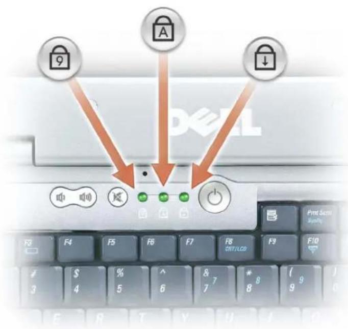
KEYBOARD STATUS LIGHTS
text_image
9 A ↓ F4 F5 F6 F7 F8 SET/LCD F3 4 5 6 7 8 9 Print Sett Systly F9 F10 E R T Y U I OThe green lights located above the keyboard indicate the following:
Turns on when the numeric keypad is enabled.
Turns on when the uppercase letter function is enabled.
Turns on when the scroll lock function is enabled.
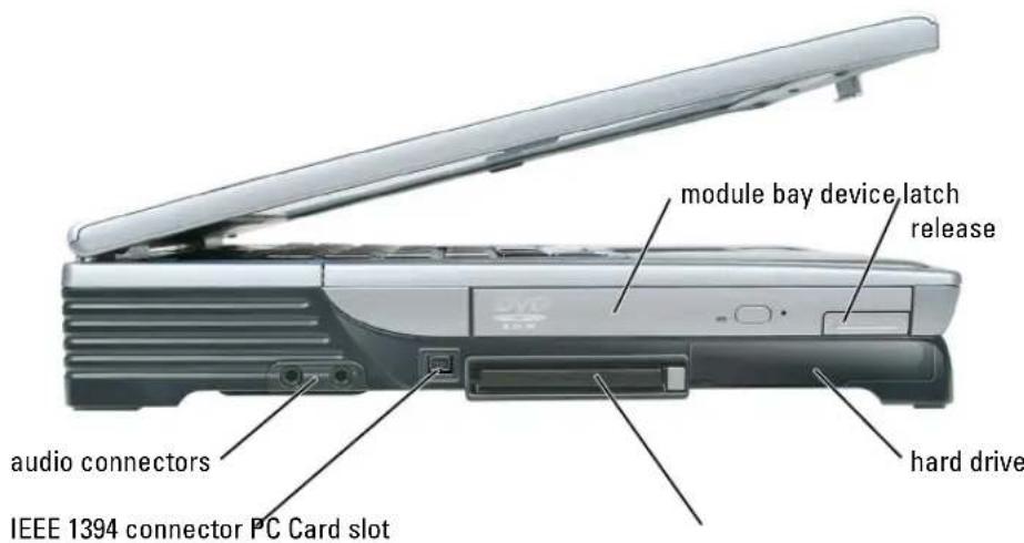
Left Side View
text_image
module bay device latch release audio connectors IEEE 1394 connector PC Card slot hard driveMODULE BAY— You can install devices such as a CD, DVD, or other optical drive in the module bay. For more information, see page 55.
DEVICE LATCH RELEASE — Press to release the device latch.
HARD DRIVE — Stores software and data.
PC CARD SLOT — Supports one PC Card, such as a modem or network adapter. The computer ships with a plastic blank installed in the slot. For more information, see the Dell™ Inspiron™ Help file. To access the help file, see page 18.
IEEE 1394 CONNECTOR — Connects devices supporting IEEE 1394 high-speed transfer rates, such as some digital video cameras.
AUDIO CONNECTORS

text_image
Diagram showing audio recording setup with microphone and headphones, labeled with DVD brandingAttach a microphone to the connector.
Attach headphones or speakers to the connector.
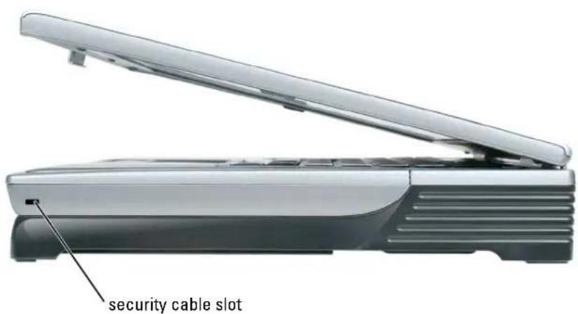
Right Side View
text_image
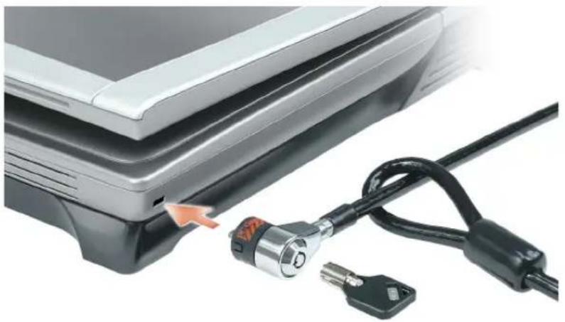
security cable slotSECURITY CABLE SLOT — Lets you attach a commercially available antitheft device to the computer. For more information, see the instructions included with the device.

NOTICE: Before you buy an antitheft device, ensure that it will work with the security cable slot.
natural_image
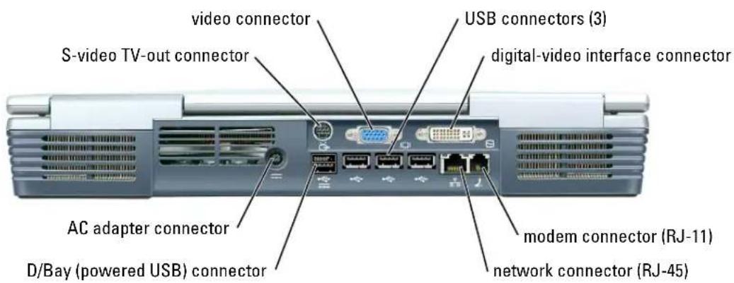
Close-up of a laptop keyboard with attached black cable and key, showing no visible text or symbolsBack View
text_image
video connector S-video TV-out connector USB connectors (3) digital-video interface connector AC adapter connector D/Bay (powered USB) connector modem connector (RJ-11) network connector (RJ-45)S-VIDEO TV-OUT CONNECTOR
Connects your computer to a TV. Also connects digital audio capable devices using the TV/digital audio adapter cable.
VIDEO CONNECTOR

Connects an external VGA-compatible monitor. For more information, see the Dell Inspiron Help file. To access the help file, see page 18.
USB CONNECTORS (3)
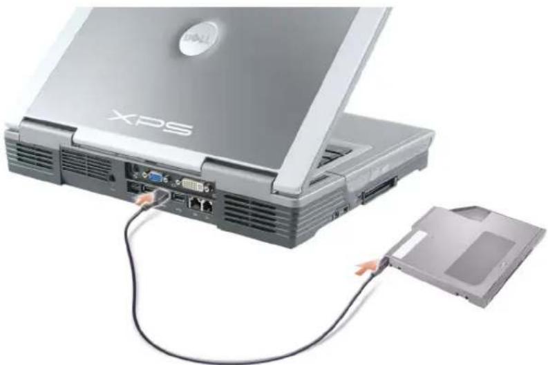
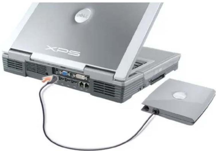
Connect USB devices, such as a mouse, keyboard, or printer. You can also connect the optional floppy drive directly to a USB connector using the optional floppy-drive cable, as shown below.
natural_image
Laptop with XPS branding connected to a hard drive via cable (no visible text or symbols beyond branding)DIGITAL-VIDEO INTERFACE (DVI) CONNECTOR
Connects an external DVI-compatible monitor. With an adapter cable, you can also connect an external VGA-compatible monitor to the DVI connector.
MODEM CONNECTOR (RJ-11)
To use the internal modem, connect the telephone line to the modem connector.
For additional information on using the modem, see the online modem documentation supplied with your computer.
NETWORK CONNECTOR (RJ-45)

NOTICE: The network connector is slightly larger than the modem connector. To avoid damaging the computer, do not plug a telephone line into the network connector.
Connects the computer to a network. The green and yellow lights next to the connector indicate activity for both wired and wireless network communications.
For information on using the network adapter, see the online network adapter documentation supplied with your computer.
D/BAY (POWERED USB) CONNECTOR

Connects powered USB devices such as a Dell™ D/Bay, which is an external module bay that accommodates an optical drive, floppy drive, or second hard drive; also connects standard USB devices.
natural_image
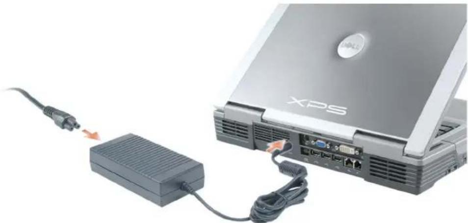
Laptop with XPS branding connected to a CD-ROM drive (no visible text or symbols on main components)AC ADAPTER CONNECTOR — Attaches an AC adapter to the computer.
natural_image
Laptop connected to a network interface via USB cable (no visible text or symbols)The AC adapter converts AC power to the DC power required by the computer. You can connect the AC adapter with your computer turned either on or off.
CAUTION: The AC adapter works with electrical outlets worldwide. However, power connectors and power strips vary among countries. Using an incompatible cable or improperly connecting the cable to the power strip or electrical outlet may cause fire or equipment damage.
NOTICE: Do not use an AC adapter rated at less than 150 W with this computer.
NOTICE: When you disconnect the AC adapter cable from the computer, grasp the connector, not the cable itself, and pull firmly but gently to avoid damaging the cable.
Bottom View
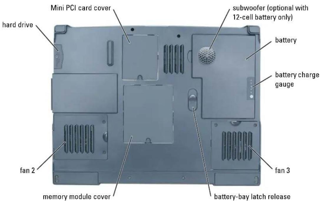
text_image
Mini PCI card cover hard drive subwoofer (optional with 12-cell battery only) battery battery charge gauge fan 2 fan 3 memory module cover battery-bay latch releaseMINI PCI CARD COVER — Covers the compartment that contains the Mini PCI card. See page 108.
SUBWOOFER — An optional component available with the 12-cell battery only. It produces a broader bass output than is provided by the speakers. See page 111.
BATTERY — When a battery is installed, you can use the computer without connecting the computer to an electrical outlet. See page 49.
BATTERY CHARGE GAUGE — Provides information on the battery charge. See page 50.
FAN — The computer uses fans to create airflow through the vents, which prevents the computer from overheating. See page 119.
BATTERY-BAY LATCH RELEASE — Releases the battery from the battery bay. See "Removing a Battery" on page 52.
MEMORY MODULE COVER — Covers the compartment that contains the memory modules. See page 105.
HARD DRIVE — Stores software and data. See page 111.
Using Your Computer
Transferring Information to a New Computer
The Microsoft ^® Windows ^® XP operating system provides a Files and Settings Transfer wizard to move data from the source computer to the new computer. You can move data such as:
• E - m a i l s
- Toolbar settings
- Window sizes
- Internet bookmarks
You can transfer the data to the new computer over a network or serial connection, or you can store it on a removable medium, such as a writable CD or floppy disk.
To prepare the new computer for the file transfer:
1 Click the Start button, point to All Programs → Accessories → System Tools, and then click Files and Settings Transfer Wizard
2 When the Files and Settings Transfer Wizard welcome screen appears, click Next.
3 On the Which computer is this? screen, click New Computer and click Next.
4 On the Do you have a Windows XP CD? screen, click I will use the wizard from the Windows XP CD and click Next.
5 When the Now go to your old computer screen appears, go to your source computer. Do not click Next at this time.
To copy data from the source computer:
1 On the old computer, insert the Windows XPOperating System CD.
2 On the Welcome to Microsoft Windows XP screen, click Perform additional tasks.
3 Under What do you want to do?, click Transfer files and settings.
4 On the Files and Settings Transfer Wizardwelcome screen, click Next.
5 On the Which computer is this? screen, click Old Computer and click Next.
6 On the Select a transfer method screen, click the transfer method you prefer.
7 On the What do you want to transfer? screen, select the items you want to transfer and click Next.
After the information has been copied, the Completing the Collection Phase screen appears.
8 Click Finish.
To transfer data to the new computer:
1 On the Now go to your old computer screen on the new computer, clickNext.
2 On the Where are the files and settings? screen, select the method you chose for transferring your settings and files and click Next.
The wizard reads the collected files and settings and applies them to your new computer.
When all of the settings and files have been applied, the Finished screen appears.
3 Click Finished and restart the new computer.
Configuring Graphics Cards
Settings and Functions
Dell configured your graphics card for optimal performance with most games and other video programs. However, some game manufacturers may recommend that you either change a setting or enable or disable a certain function for a game to properly run. You may also want to readjust settings to better fit your gaming style.
Some settings, such as Direct3D or OpenGL, enable you to adjust the card for higher performance or for higher image quality. Other settings, such as contrast or color level, are cosmetic adjustments.
Certain high-end graphics cards are available with TV-out support, which enables you to connect a TV to your computer, in addition to a monitor. A TV-out configuration is ideal for watching movies using an optional DVD player or for giving presentations. For information on connecting a TV to your computer, see page 35.
For information and instructions on adjusting your graphics card's operating mode, settings, and functions:
1 Click the Start button and click Help and Support.
2 Click User and system guides.
3 Locate and click the guide for your graphics card.
Connecting Your Computer to a TV or Audio Device

NOTE: Unless otherwise indicated, some of the video and audio cables required for connecting your computer to a TV may not be included with your computer. Cables may be purchased at most consumer electronics stores.
Your computer has an S-video TV-out connector that, together with the TV/digital audio adapter cable (available from Dell), enables you to connect the computer to a TV and/or stereo audio device. The TV/digital audio adapter cable provides connectors for an S-video cable, a composite video cable, and an S/PDIF digital audio cable.
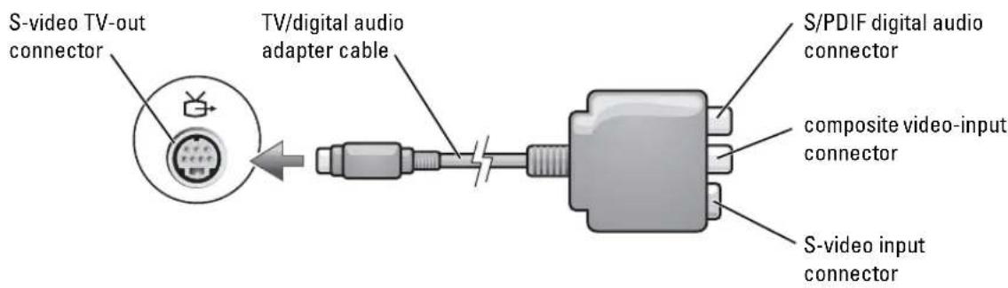
text_image
S-video TV-out connector TV/digital audio adapter cable S/PDIF digital audio connector composite video-input connector S-video input connectorYour TV has either an S-video input connector or a composite video-input connector. Depending on what type of connector is available on your TV, you can use an S-video cable (included with your Dell computer) or a commercially available composite video cable to connect your computer to your TV. For audio devices without support for S/PDIF digital audio, you can use the audio connector on the side of the computer to connect the computer to your audio device.
It is recommended that you connect video and audio cables to your computer in one of the following combinations.

NOTE: See the diagrams at the beginning of each subsection to help you determine which method of connection you should use.
• S-video and standard audio (see page 36)
• S-video and S/PDIF digital audio (see page 37)
• Composite video and standard audio (see page 39)
• Composite video and S/PDIF digital audio (see page 40)
When you finish connecting the video and audio cables between your computer and your TV, you must enable your computer to work with the TV. See "Enabling the Display Settings for a TV" on page 43 to ensure that the computer recognizes and works properly with the TV. Additionally, if you are using S/PDIF digital audio, see "Enabling S/PDIF Digital Audio" on page 42.
S-Video and Standard Audio
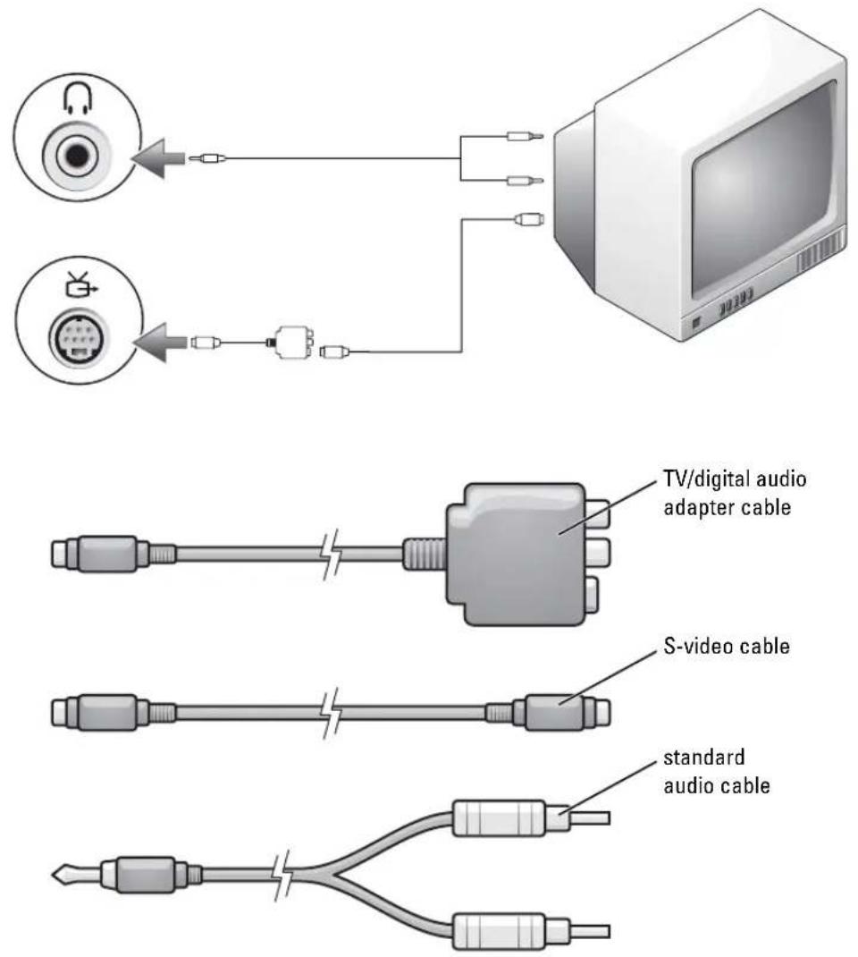
text_image
TV/digital audio adapter cable S-video cable standard audio cable1 Turn off the computer and the TV and/or audio device that you want to connect.

NOTE: You can connect an S-video cable directly to the S-video TV-out connector on the computer (without the TV/digital audio adapter cable) if your TV or audio device supports S-video but not S/PDIF digital audio.
2 Connect the TV/digital audio adapter cable to the S-video TV-out connector on your computer.
3 Plug one end of the S-video cable in to the S-video input connector on the TV/digital audio adapter cable.
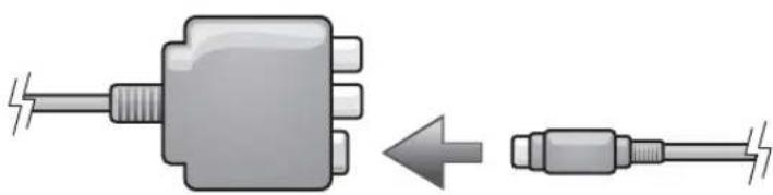
natural_image
Diagram showing a plug-in connector transforming into a cable (no text or symbols present)4 Plug the other end of the S-video cable in to the S-video input connector on your TV.
5 Plug the single-connector end of the audio cable in to the headphone connector on your computer.
6 Plug the two RCA connectors on the other end of the audio cable in to the audio input connectors on your TV or other audio device.
7 Turn on the TV and any audio device that you connected, and then turn on the computer.
8 See "Enabling the Display Settings for a TV" on page 43 to ensure that the computer recognizes and works properly with the TV.
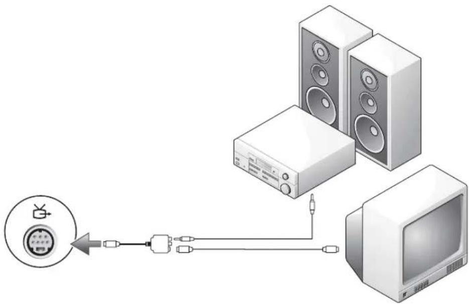
S-Video and S/PDIF Digital Audio
natural_image
Diagram showing connections between a TV, audio equipment, and a monitor (no text or symbols present)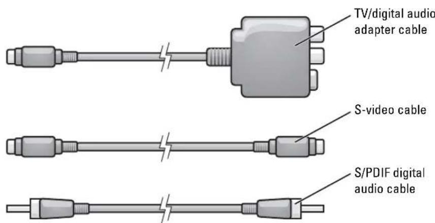
text_image
TV/digital audio adapter cable S-video cable S/PDIF digital audio cable1 Turn off the computer and the TV and/or audio device that you want to connect.
2 Connect the TV/digital audio adapter cable to the S-video TV-out connector on your computer.
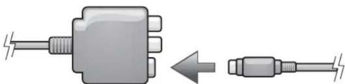
3 Plug one end of the S-video cable in to the S-video input connector on the TV/digital audio adapter cable.
natural_image
Diagram showing a mechanical component with a left-pointing arrow indicating transformation or assembly (no text or symbols present)4 Plug the other end of the S-video cable in to the S-video input connector on the TV.
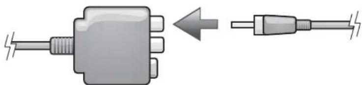
5 Plug one end of the S/PDIF digital audio cable in to the digital audio connector on the TV/digital audio adapter cable.
natural_image
Diagram showing a mechanical component before and after disassembly, with no text or symbols present.6 Plug the other end of the S/PDIF digital audio cable in to the audio input connector on your TV or other audio device.
7 Turn on the TV, turn on any audio device that you connected (if applicable), and then turn on the computer.
8 See "Enabling the Display Settings for a TV" on page 43 to ensure that the computer recognizes and works properly with the TV.
Composite Video and Standard Audio
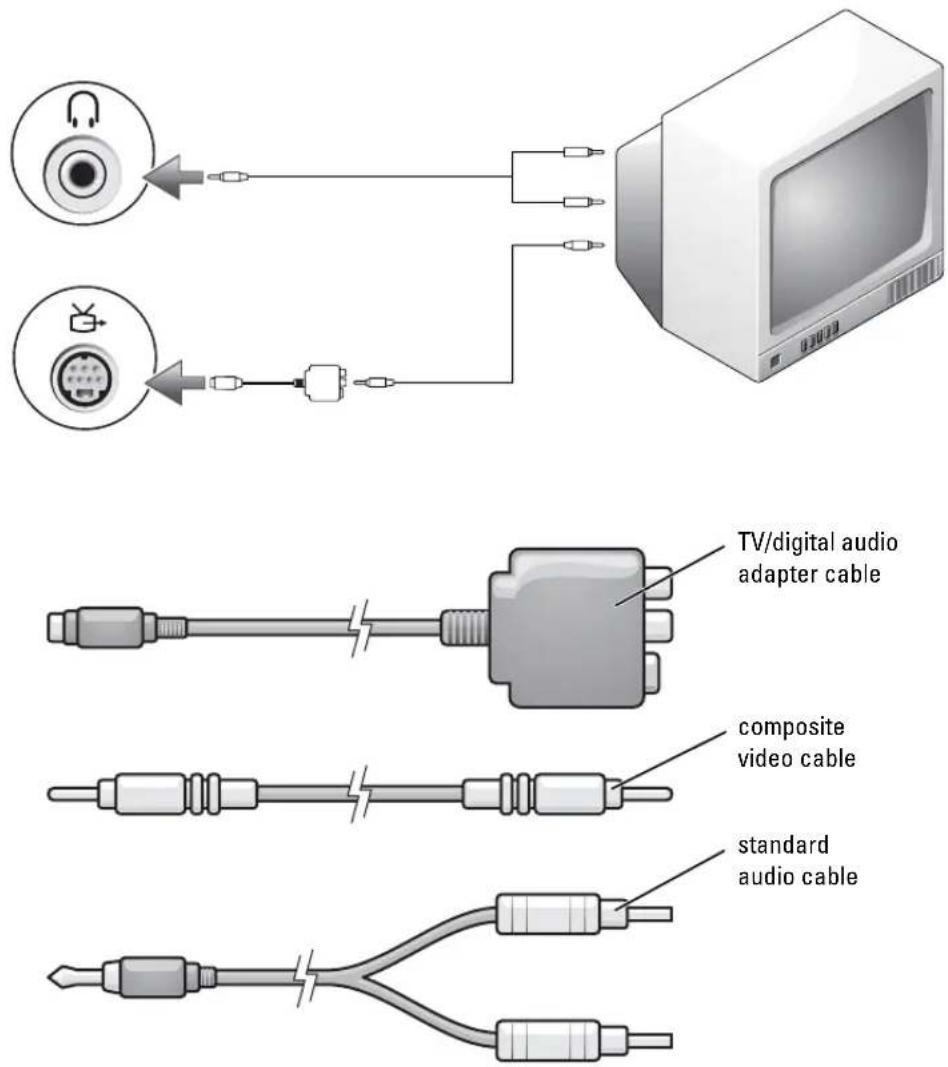
text_image
TV/digital audio adapter cable composite video cable standard audio cable1 Turn off the computer and the TV and/or audio device that you want to connect.
2 Connect the TV/digital audio adapter cable to the S-video TV-out connector on the computer.
3 Plug one end of the composite video cable in to the composite video-input connector on the TV/digital audio adapter cable.
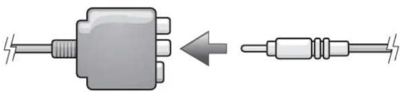
natural_image
Diagram showing a mechanical component transforming into a resistor, with no text or symbols present.4 Plug the other end of the composite video cable in to the composite video-input connector on the TV.
5 Plug the single-connector end of the audio cable in to the headphone connector on the computer.
6 Plug the two RCA connectors on the other end of the audio cable in to the audio input connectors on your TV or other audio device.
7 Turn on the TV, turn on any audio device that you connected (if applicable), and then turn on the computer.
8 See "Enabling the Display Settings for a TV" on page 43 to ensure that the computer recognizes and works properly with the TV.
Composite Video and S/PDIF Digital Audio

natural_image
Diagram showing connections between a device, audio equipment, and a television (no text or symbols present)1 Turn off the computer and the TV and/or audio device that you want to connect.
2 Connect the TV/digital audio adapter cable to the S-video TV-out connector on the computer.
3 Plug one end of the composite video cable in to the composite video-input connector on the TV/digital audio adapter cable.
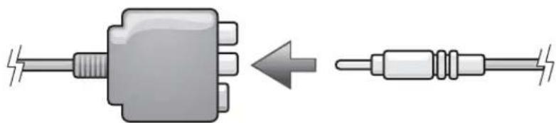
natural_image
Diagram showing a mechanical component transforming into a resistor, with no text or symbols present.4 Plug the other end of the composite video cable in to the composite video-input connector on the TV.
5 Plug one end of the S/PDIF digital audio cable in to the S/PDIF audio connector on the TV/digital audio adapter cable.
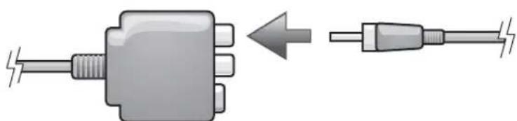
natural_image
Diagram showing a mechanical component before and after assembly, with no visible text or symbols6 Plug the other end of the digital audio cable in to the S/PDIF input connector on your TV or other audio device.
7 Turn on the TV, turn on any audio device that you connected (if applicable), and then turn on the computer.
8 See "Enabling the Display Settings for a TV" on page 43 to ensure that the computer recognizes and works properly with the TV.
Enabling S/PDIF Digital Audio
If your computer has a DVD drive, you can enable Dolby Digital 5.1 audio for DVD playback.
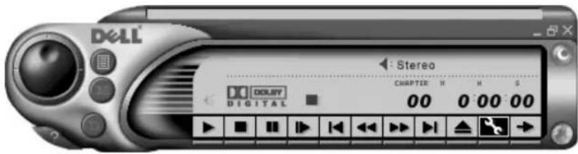
1 Double-click the CyberLink PowerDVD icon on the Microsoft® Windows® desktop.
text_image
Dell Stereo CHAPTER H M S CD/CD/ Digital 00 0:00:002 Insert a DVD into the DVD drive.
If the DVD begins playing, click the stop button.
3 Click the properties (wrench) icon.
4 Click the Audio tab.
5 Click Enable S/PDIF output .
6 Click Apply.
7 Click OK.
Enabling S/PDIF in the Windows Audio Driver
NOTE: Enabling S/PDIF in Windows disables the sound from the headphone connector.
1 Double-click the speaker icon in the Windows notification area.
2 Click the Options menu and then click Advanced Controls.
3 Click Advanced.
4 Click Enable S/PDIF.
5 Click Close.
6 Click OK.
Setting Up the Dolby Headphone
NOTE: The Dolby headphone feature is available only if your computer has a DVD drive.
1 Double-click the Cyberlink PowerDVD icon on the Windows desktop.
2 Click the Properties icon.
3 Click the Dolby Headphone tab.
4 Click Enable Dolby Headphone .
NOTE: Icon labels may be visible only when you place the cursor over the icon.
5 Select one of the four options to set the level of surround sound effects. Option 1 is a baseline stereo option and Options 2, 3, and 4 are surround sound levels.
6 Click Apply, and then click OK to close the Properties window.
7 Click Exit.
Enabling the Display Settings for a TV
Your computer has an ATI video-controller card. To enable the display settings for a TV:

NOTE: See the documentation that came with your TV, and ensure that you properly configure and connect the TV before you enable the display settings.
1 Click the Start button and click Control Panel
2 Click Appearances and Themes.
3 Under or pick a Control Panel icon, click Display.
4 Click the Settings tab and click Advanced.
5 Click the Displays tab.
6 Click the upper-left corner of the TV button to enable the TV.
7 Click OK.
Connecting Monitors

NOTE: If you are connecting two monitors that both have VGA connectors, you must have the optional VGA adapter, available from Dell. If you are connecting two flat-panel monitors, at least one of them must have a VGA connector. If you are connecting a television, you may connect only one monitor (VGA or DVI) in addition to the television.
This section provides instructions for connecting and enabling monitors. The instructions tell you how to connect either one or two monitors (each with a VGA connector), one monitor with a VGA connector and/or one monitor with a DVI connector, and one monitor of either type and/or a television.
1 Connect the monitor cables to the connectors on the back of the computer.
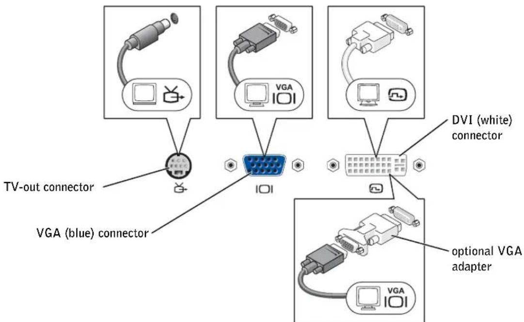
If you are connecting one VGA monitor, connect it to the VGA (blue) connector on the computer.
If you are connecting one DVI monitor, connect it to the DVI (white) connector on the computer.
If you are connecting two monitors that both have VGA connectors:
a Connect one of the monitors to the VGA (blue) connector on the computer.
b Connect the other monitor to the optional VGA adapter and connect the VGA adapter to the DVI (white) connector on the computer.
text_image
TV-out connector VGA (blue) connector DVI (white) connector optional VGA adapterIf you are connecting two monitors, and one monitor has a VGA connector and the other monitor has a DVI connector:
a Connect the VGA connector on the monitor to the VGA (blue) connector on the computer.
b Connect the DVI connector on the other monitor to the DVI (white) connector on the computer.

NOTE: To connect a television to your computer, you must use the S-video cable included with your computer.
If you are connecting two monitors and one of the monitors is a television:
a Connect one end of the S-video cable to the TV-out connector on the computer.
b Connect the other end of the S-video cable to the S-video input connector on your television.
c Connect the VGA or DVI monitor as described on page 44.
2 Enable clone mode or extended desktop mode in the display settings.
- In clone mode, both monitors display the same image.
- In extended desktop mode, you can drag objects from one screen to the other, effectively doubling the amount of viewable work space.
For information on changing the display settings for your video card, see the user's guide in the Help and Support Center (click the Start button, click Help and Support, click User and system guides, click Device guides, and then click the guide for your video card).
Using CDs and DVDs
For information about using CDs and DVDs in your computer, see the Dell Inspiron Help file. To access the help file, see page 18.
Copying CDs and DVDs
NOTE: Ensure that you follow all copyright laws when you create CDs or DVDs.
This section applies only to computers that have a CD-R, CD-RW, DVD+RW, DVD+R, or DVD/CD-RW combo drive.
The following instructions show how to make an exact copy of a CD or DVD. You can also use Sonic RecordNow for other purposes, including creating CDs from audio files on your computer and creating MP3 CDs. For instructions, see the Sonic RecordNow documentation that came with your computer. Open Sonic RecordNow, click the question mark icon in the upper-right corner of the window, and then click RecordNow Help or RecordNow Tutorial.
How to Copy a CD or DVD
NOTE: If you have a DVD/CD-RW combo drive and you experience recording problems, check for available software patches at the Sonic support website at support.sonic.com.
Currently, there are five DVD writeable disc formats available: DVD+R, DVD+RW, DVD-R, DVD-RW and DVD-RAM. The DVD-writeable drives installed in Dell™ computers will write to DVD+R and DVD+RW media, as well as read DVD-R and DVD-RW media, but the drives will not write to and may not read DVD-RAM media. The commercially available DVD players for home theater systems may or may not read all five formats.
NOTE: Most commercial DVDs have copyright protection and cannot be copied using Sonic RecordNow.
1 Click the Start button, point to All Programs→ Sonic→ RecordNow!→ RecordNow!
2 Click either the audio tab or the data tab, depending on the kind of CD or DVD you are planning to copy.
3 Click Exact Copy.
4 To copy the CD or DVD:
- If you have one CD or DVD drive, ensure that the settings are correct and click Copy. The computer reads your source CD or DVD and copies it to a temporary folder on your computer hard drive.
When prompted, insert a blank CD or DVD into the CD or DVD drive and click OK.
- If you have two CD or DVD drives, select the drive into which you have inserted your source CD or DVD and click Copy. The computer copies the data on the CD or DVD to the blank CD or DVD.
Once you have finished copying the source CD or DVD, the CD or DVD that you have created automatically ejects.
Using Blank CD-Rs, CD-RWs, DVD+Rs, and DVD+RWs
Your CD-RW drive can write to two different types of recording media—CD-Rs and CD-RWs (including High-Speed CD-RWs). Use blank CD-Rs to record music or permanently store data files. After creating a CD-R, you cannot write to that CD-R again without changing your method of recording (see the Sonic documentation for more information). Use blank CD-RWs to write to CDs or to erase, rewrite, or update data on CDs.
Your DVD writeable drive can write to four different types of recording media—CD-Rs, CD-RWs (including IHigh-Speed CD-RWs), DVD+Rs, and DVD+RWs. Blank DVD+Rs can be used to permanently store large amounts of information. After creating a DVD+R disc, you may not be able to write to that disc again, depending on whether or not the disc is "finalized" or "closed" (the final stage of the disc creation process). Use blank DVD+RWs when you will need to erase, rewrite, or update the information on that disc later.
Helpful Tips
- Use Microsoft ^ Windows ^ Explorer to drag and drop files to a CD-R or CD-RW only after you start Sonic RecordNow and open a RecordNow project.
- You must use CD-Rs to burn music CDs that you want to play in regular stereos. CD-RWs do not play in most home or car stereos.
- You cannot create audio DVDs with Sonic RecordNow.
- Music MP3 files can be played only on MP3 players or on computers that have MP3 software installed.
- Do not burn a blank CD-R or CD-RW to its maximum capacity; for example, do not copy a 650-MB file to a 650-MB blank CD. The CD-RW drive needs 1 or 2 MB of the blank CD to finalize the recording.
- Use a blank CD-RW to practice CD recording until you are familiar with CD recording techniques. If you make a mistake, you can erase the data on the CD-RW and try again. You can also use blank CD-RWs to test music file projects before you record the project permanently to a blank CD-R.
• See the Sonic support website at support.sonic.com for additional information.
Optimizing Performance
Your Dell™ Inspiron™ computer is equipped with the Intel® 865PE chip set, which is designed to support the Intel Pentium® 4 processor with Hyper-Threading (HT) technology to deliver the highest level of system performance. The Intel 865PE chip set is highly integrated; it provides dual-channel PC3200 memory interfaces and an 8X AGP graphics interface.
DDR Memory and Processor Front-Side Bus
The performance of your computer's DDR memory depends on the type of memory installed and the clock speed of your processor. For your computer, the memory type is PC3200, so for an 800-MHz front-side bus processor, the memory performs at 400 MHz.
Processor Type Processor Front-Side Bus Memory Type DDR Memory
Performance
| Intel Pentium 4 with Hyper-Threading technology | 800-MHz front-side bus PC3200 400 MHz |

NOTE: To get dual-channel memory bandwidth capability, you must always have two memory modules installed and they must be of the same memory capacity.
For information on installing memory, see page 105. For more information on the type of memory supported by your computer, see page 144.
Hyper-Threading
Hyper-Threading is an Intel ^® technology that can enhance overall computer performance by allowing one physical processor to function as two logical processors, capable of performing certain tasks simultaneously. The Microsoft ^® Windows ^® XP operating system is optimized to take advantage of Hyper-Threading technology. While many programs can benefit from Hyper-Threading, some programs have not been optimized for Hyper-Threading and may require an update from the software manufacturer. Contact the software manufacturer for updates and information about using Hyper-Threading with your software.
Using a Battery
Battery Performance

CAUTION: Before you begin this procedure, read the safety instructions at the front of this document (see page 11).

NOTE: Batteries for portable computers are covered only during the initial one-year period of the limited warranty for your computer. For more information about the Dell warranty for your computer, see "Limited Warranties" on page 171 or the separate paper warranty document that shipped with your computer.
For optimal computer performance and to help preserve BIOS settings, operate your Dell ^™ portable computer with the main battery installed at all times. Use a battery to run the computer when it is not connected to an electrical outlet. One battery is supplied as standard equipment in the battery bay.
Battery operating time varies depending on operating conditions.
Operating time is significantly reduced when you perform operations including, but not limited to, the following:
• Using DVD, DVD+RW, and CD-RW drives.
- Using wireless communications devices, PC Cards, or USB devices.
- Using high-brightness display settings, 3D screen savers, or other power-intensive programs such as 3D games.
- Running the computer in maximum performance mode. (See "Power Management" in the Dell Inspiron IHelp file for more information. To access the help file, see page 18.)

NOTE: It is recommended that you connect your computer to an electrical outlet when writing to a CD or DVD.
You can check the battery charge before or after you insert the battery into the computer. You can also set power management options to alert you when the battery charge is low.

CAUTION: Using an incompatible battery may increase the risk of fire or explosion. Replace the battery only with a compatible battery purchased from Dell. The lithium-ion battery is designed to work with your Dell computer. Do not use a battery from other computers with your computer.

CAUTION: Do not dispose of batteries with household waste. When your battery no longer holds a charge, call your local waste disposal or environmental agency for advice on disposing of a lithium-ion battery. See "Battery Disposal" on page 15.

CAUTION: Misuse of the battery may increase the risk of fire or chemical burn. Do not puncture, incinerate, disassemble, or expose the battery to temperatures above 65^ C ( 149^ F). Keep the battery away from children. Handle damaged or leaking batteries with extreme care. Damaged batteries may leak and cause personal injury or equipment damage.
Checking the Battery Charge
The Dell QuickSet Battery Meter, the Microsoft ^® Windows ^® Power Meter window and icon, the battery charge gauge, and the low-battery warning provide information on the battery charge.
Dell™ QuickSet Battery Meter
If Dell QuickSet is installed, press
The Battery Meter window displays status, charge level, and charge completion time for the battery in your computer.
The following icons appear in the Battery Meter window:

- The computer is running on battery power.
• The battery is discharging or idle.

- The computer is connected to an electrical outlet and running on AC power.
• The battery is charging.

- The computer is connected to an electrical outlet and running on AC power.
• The battery is discharging, idle, or charging.
For more information about QuickSet, right-click the Icon in the taskbar, and click Help.
Microsoft® Windows® Power Meter
The Windows Power Meter indicates the remaining battery charge. To check the Power Meter, double-click the icon on the taskbar. For more information about the Power Meter tab, see "Power Management" in the Dell Inspiron Help file. To access the help file, see page 18.
If the computer is connected to an electrical outlet, a lighton appears in the taskbar.
Charge Gauge
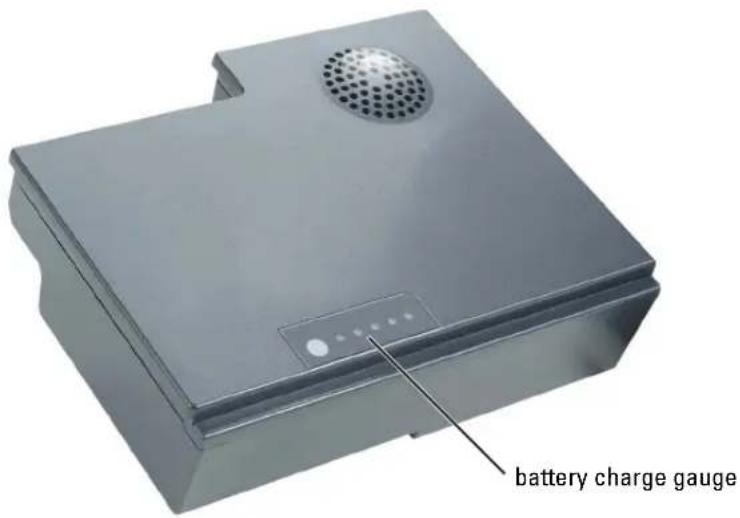
Press the status button on the battery charge gauge to illuminate the charge-level lights. Each light represents approximately 20 percent of the total battery charge. For example, if the battery has 80 percent of its charge remaining, four of the lights are on. If no lights appear, the battery has no charge.
text_image
battery charge gaugeLow-Battery Warning

NOTICE: To avoid losing or corrupting data, save your work immediately after a low-battery warning.
Then connect the computer to an electrical outlet. If the battery runs completely out of power, hibernate mode begins automatically.
A pop-up window warns you when the battery charge is approximately 90 percent depleted. For more information about low-battery alarms, see "Power Management" in the Dell Inspiron Help file. To access the help file, see page 18.
Charging the Battery

NOTE: The AC adapter charges a completely discharged battery in approximately 1.5 hours with the computer turned off. Charge time is longer with the computer turned on. You can leave the battery in the computer as long as you like. The battery's internal circuitry prevents the battery from overcharging.
When you connect the computer to an electrical outlet or install a battery while the computer is connected to an electrical outlet, the computer checks the battery charge and temperature. If necessary, the AC adapter then charges the battery and maintains the battery charge.
If the battery is hot from being used in your computer or being in a hot environment, the battery may not charge when you connect the computer to an electrical outlet.
The battery is too hot to start charging if the ⏻ light flashes alternately green and orange.
Disconnect the computer from the electrical outlet and allow the computer and the battery to cool to room temperature. Then connect the computer to an electrical outlet to continue charging the battery.
For more information about resolving problems with a battery, see "Power Problems" on page 83.
Removing a Battery

CAUTION: Before performing these procedures, disconnect all cables from the computer.
1 Ensure that the computer is turned off or disconnected from an electrical outlet.
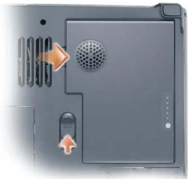
2 Slide and hold the battery-bay latch release on the bottom of the computer, and then remove the battery from the bay.
natural_image
Close-up of a laptop's front panel showing ventilation slots, a perforated grille, and a speaker (no text or symbols visible)Installing a Battery
1 Slide the battery into the bay at a 45-degree angle.
2 Press the other side down until the latch release clicks.

natural_image
Close-up of a black electronic device with ventilation slots and a perforated cover, showing orange arrows indicating component movement (no text or symbols)Storing a Battery
Remove the battery when you store your computer for an extended period of time. A battery discharges during prolonged storage. After a long storage period, recharge the battery fully before you use it.
Using the Module Bay
About the Module Bay

CAUTION: Before you begin this procedure, read the safety instructions at the front of this document (see page 11).
You can install devices such as a floppy drive, CD drive, CD-RW drive, DVD drive, CD-RW/DVD drive, DVD+RW, or second hard drive in the module bay.
Your Dell ^™ Inspiron ^™ computer ships with a CD, DVD, or other optical drive installed in the module bay.
Removing and Installing Devices While the Computer Is Turned Off

NOTICE: To prevent damage to devices, store them in a safe, dry place when they are not installed in the computer. Avoid pressing down on them or placing heavy objects on top of them.
1 Press the device latch release.
The latch release ejects partway.
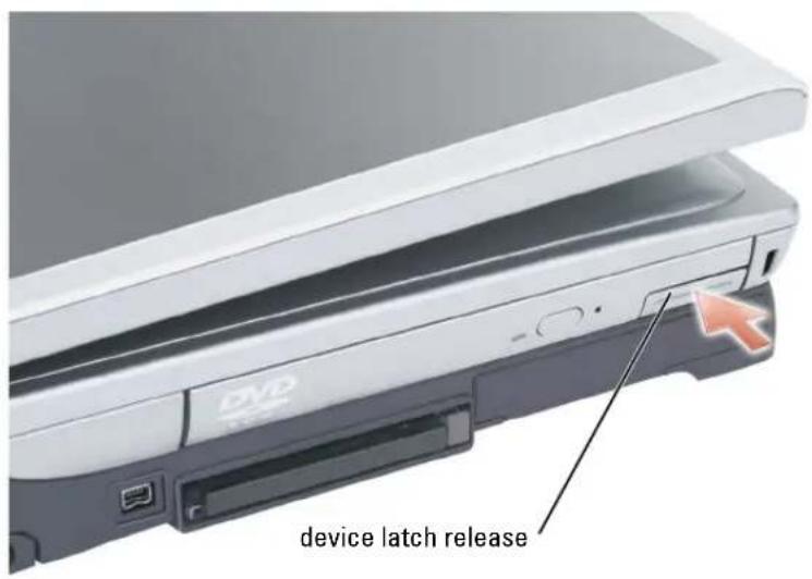
text_image
DV device latch release2 Pull the device out of the module bay.
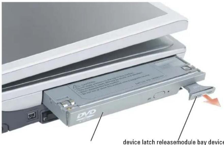
text_image
device latch releasemodule bay device3 Push the new device into the bay until it clicks.
Removing and Installing Devices While the Computer Is Running
1 Before ejecting the device, double-click the Safely Remove Hardware icon on the taskbar, click the device you want to eject, and click Stop.
NOTICE: To prevent damage to devices, store them in a safe, dry place when they are not installed in the computer. Avoid pressing down on them or placing heavy objects on top of them.
2 Press the device latch release.
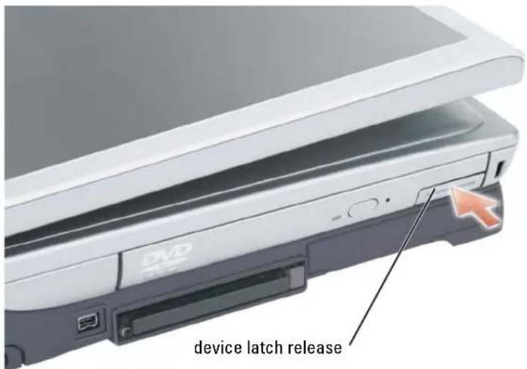
text_image
device latch release3 Pull the device out of the module bay.
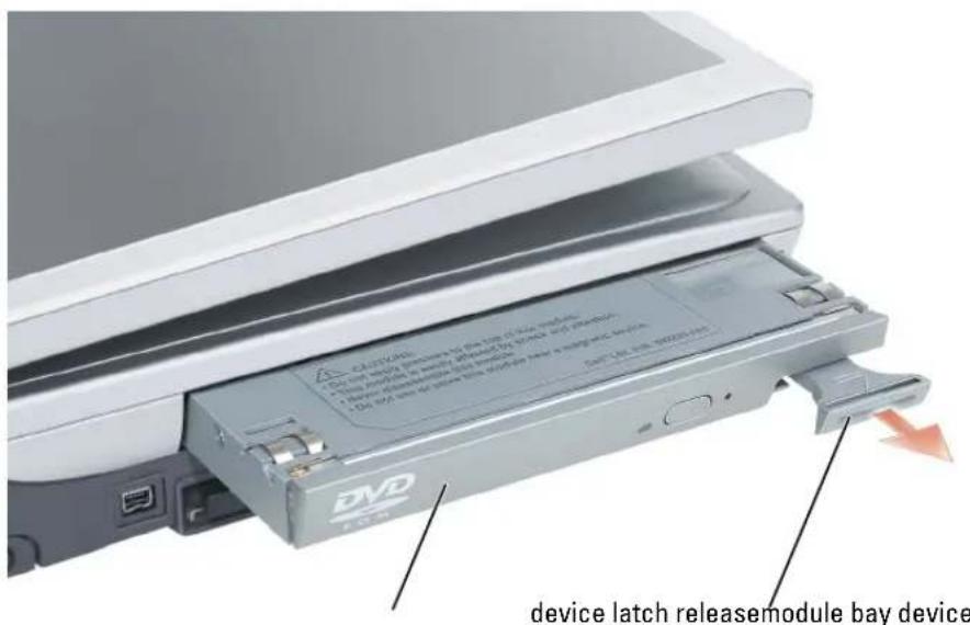
text_image
Device latch releasemodule bay device4 Push the new device into the bay until it clicks.
The operating system automatically recognizes the device.
5 If necessary, enter your password to unlock your computer.
Using the Keyboard and Touch Pad
Numeric Keypad
The numeric keypad functions like the numeric keypad on an external keyboard. Each key on the keypad has multiple functions. The keypad numbers and symbols are marked in blue on the middle of the keypad keys.
- To type a number or symbol, hold down
and press the desired key. - To enable the keypad, press
. The light indicates that the keypad is active. - To disable the keypad, press
again.
Key Combinations
System Functions
<Ctrl><Shift><Esc> Opens the Task Manager window
<Num Lk> Enables and disables the numeric keypad
<Fn><Num Lk> Enables and disables the scroll lock function
Battery
<Fn><F3> Displays the Dell™ QuickSet Battery Meter (see page 50)
CD or DVD Tray
<Fn><F10> Ejects the tray out of the drive if Dell QuickSet is installed
Display Functions
| Switches the video image to the next display option | |
| and up-arrow key Increases brightness on the integrated display only (not on an external monitor) | |
| and down-arrow key Decreases brightness on the integrated display only (not on an external monitor) |
Radios (Including Wireless Networking and PC Cards With Bluetooth® Wireless Technology)
| Enables and disables radios, including wireless networking and the PC Card with Bluetooth wireless technology. |
Power Management
| Activates a power management mode. You can reprogram this keyboard shortcut to activate a different power management mode using the Advanced tab in the Power Options Properties window. For instructions, see "Power Management" in the Dell Inspiron Help file. To access the help file, see page 18. |
Speaker Functions
| <Fn><Page Up> Increases the volume of the integrated speakers and external speakers, if attached |
| <Fn><Page Dn> Decreases the volume of the integrated speakers and external speakers, if attached |
| <Fn><End> Enables and disables the integrated speakers and external speakers, if attached |
Microsoft® Windows® Logo Key Functions
| Windows logo key and | Minimizes all open windows |
| Windows logo key and | Maximizes all windows |
| Windows logo key and | Runs Windows Explorer |
| Windows logo key and | Opens the Run dialog box |
| Windows logo key and | Opens the Search Results dialog box |
| Windows logo key and | Opens the Search Results-Computer dialog box (if the computer is connected to a network) |
| Windows logo key and | Opens the System Properties dialog box |
To adjust keyboard operation, such as the character repeat rate, open the Control Panel, click Printers and Other Hardware, and click Keyboard.
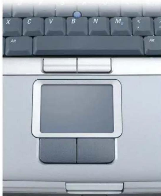
Touch Pad
The touch pad detects the pressure and movement of your finger to allow you to move the cursor on the display. Use the touch pad and touch pad buttons as you would use a mouse.
natural_image
Close-up of a laptop keyboard with a blank control panel and keyboard, no visible text or symbols on the keys.• To move the cursor, lightly slide your finger over the touch pad.
- To select an object, lightly tap once on the surface of the touch pad or use your thumb to press the left touch-pad button.
- To select and move (or drag) an object, position the cursor on the object and tap down-up-down on the touch pad. On the second down motion, leave your finger on the touch pad and move the selected object by sliding your finger over the surface.
- To double-click an object, position the cursor on the object and tap twice on the touch pad or use your thumb to press the left touch-pad button twice.
You can also use the track stick to move the cursor. Press the track stick left, right, up, or down to change the direction of the cursor on the display. Use the track stick and track stick buttons as you would use a mouse.
Customizing the Touch Pad and Track Stick
You can use the Mouse Properties window to disable the touch pad and track stick or adjust their settings.
1 Click the Start button, click Control Panel, click Printers and Other Hardware, and then click Mouse.
2 In the Mouse Properties window:
- Click the Device Select tab to disable the touch pad and track stick.
- Click the Pointer tab to adjust touch pad and track stick settings.
3 Select the desired settings and click Apply.
4 Click OK to save the settings and close the window.
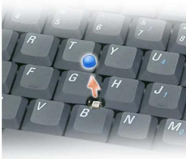
Changing the Track Stick Cap
You can replace your track stick cap if it wears down from prolonged use. You can purchase additional caps by visiting the Dell website at www.dell.com
text_image
R T Y U4 F G H J1 V B N M01 Pull the cap off the track stick.
2 Align the new cap over the square track-stick post and gently press the cap down onto the post.

NOTICE: The track stick can damage the display if it is not properly seated on the post.
3 Test the track stick to ensure that the cap is seated properly.
Setting Up a Home and Office Network
Connecting to a Network Adapter
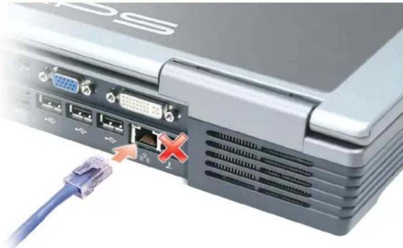
Before you connect your computer to a network, the computer must have a network adapter installed and a network cable connected to it.
To connect a network cable:
1 Connect the network cable to the network adapter connector on the back of your computer.
NOTE: Insert the cable until it clicks into place, and then gently pull it to ensure that it is secure.
2 Connect the other end of the network cable to a network connection device, such as a network wall jack.
NOTE: Do not use a network cable with a telephone wall jack.
natural_image
Close-up of a laptop internal interface with ports, connectors, and a blue cable showing connection (no text or symbols visible)Network Setup Wizard
The Microsoft ^® Windows ^® XP operating system provides a Network Setup Wizard to guide you through the process of sharing files, printers, or an Internet connection between computers in a home or small office.
1 Click the Start button, point to All Programs → Accessories → Communications, and then click Network Setup Wizard.
2 On the welcome screen, click Next.
3 Click Checklist for creating a network.
NOTE: Selecting the connection method labeled "This computer connects directly to the Internet" enables the integrated firewall provided with Windows XP.
4 Complete the checklist and required preparations.
5 Return to the Network Setup Wizard and follow the instructions on the screen.
Connecting to a Wireless Local Area Network
NOTE: These networking instructions do not apply to PC Cards with Bluetooth ^® wireless technology or cellular products.
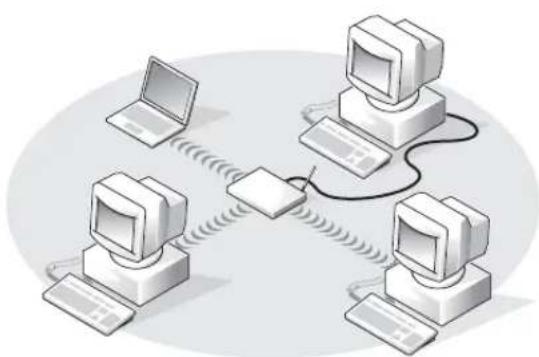
Determining Your Network Type
NOTE: Most wireless networks are of the infrastructure type.
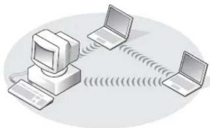
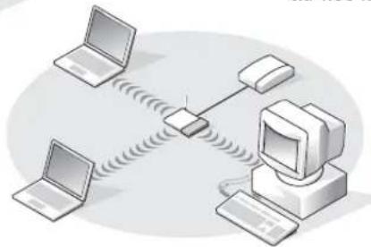
Wireless networks fall into three categories—infrastructure networks, ad-hoc networks, and home networks. An infrastructure network uses routers or access points to connect several computers. An ad-hoc network does not use routers or access points and consists of computers that broadcast to one another. A home network typically employs high-speed Internet access such as DSL or cable, and an access point or router. For additional assistance with setting up your wireless connection, go to support.dell.com and search for the keywordwireless setup.
natural_image
Illustration of four vintage desktop computers connected via a central device (no text or symbols present)infrastructure network
natural_image
Illustration of a desktop computer connected to two laptops via wireless signal waves (no text or symbols)ad-hoc network
natural_image
Illustration of a network device with two laptops and a central computer connected via wireless links (no text or symbols)home network
Connecting to a Wireless Network in Microsoft® Windows® XP
Your wireless network card requires specific software and drivers in order to connect to a network. The software is already installed. If the software is removed or corrupted, follow the instructions included in the user's guide for your wireless network card. The user's guide is located on your Drivers and Utilities CD (that came with your computer) in the "User's Guides-Network User's Guides" category. The user's guide is also available on the Dell Support website at support.dell.com.
1 Click the Start button, click Control Panel, and then click Switch to Classic View
2 Double-click Network Connections.
3 Click Wireless Network Connection.
The Wireless Network Connection icon is highlighted.
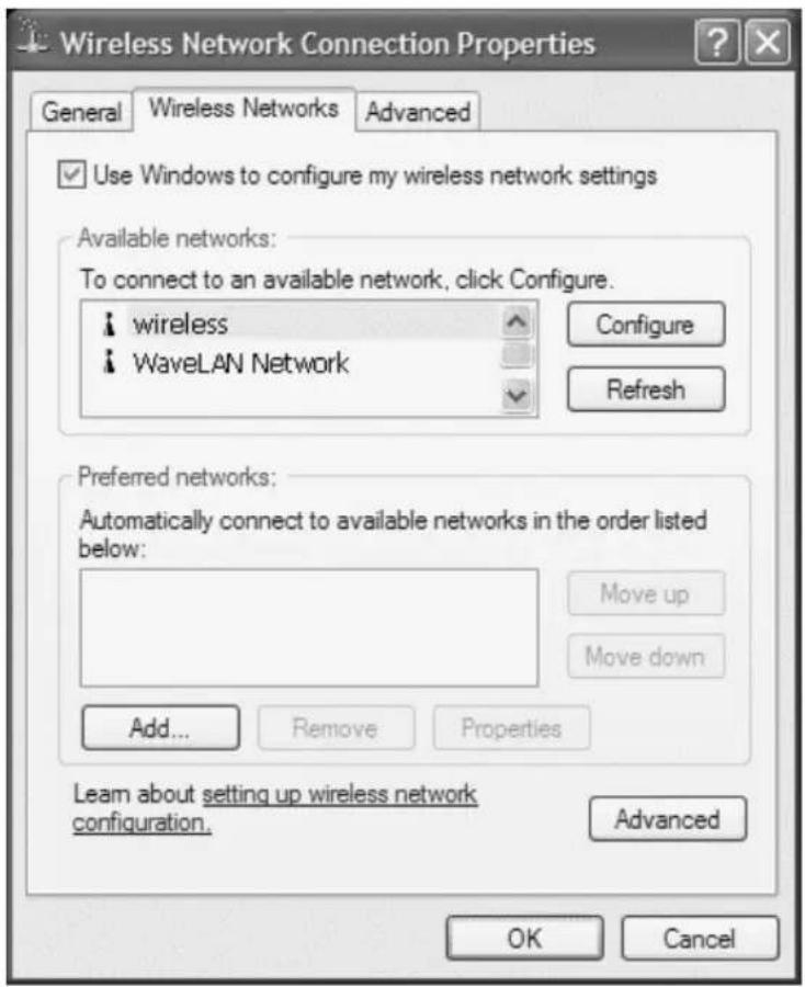
4 Under Network Tasks in the left-hand pane, click Change settings of this connection.
The Wireless Network Connection Properties window appears.
5 Click the Wireless Networks tab.

NOTE: The names of wireless networks that your computer can detect are listed under Available Networks.
text_image
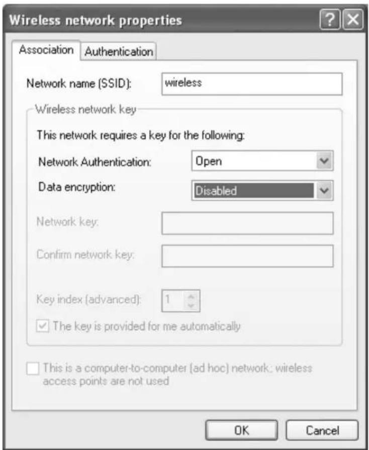
Wireless Network Connection Properties General Wireless Networks Advanced Use Windows to configure my wireless network settings Available networks: To connect to an available network, click Configure. wireless WaveLAN Network Configure Refresh Preferred networks: Automatically connect to available networks in the order listed below: Move up Move down Add... Remove Properties Learn about setting up wireless network configuration. Advanced OK Cancel6 Click Add.
The Wireless network properties window appears.
text_image
Wireless network properties Association Authentication Network name (SSID): wireless Wireless network key This network requires a key for the following: Network Authentication: Open Data encryption: Disabled Network key: Confirm network key: Key index (advanced): 1 ✓ The key is provided for me automatically This is a computer-to-computer (ad hoc) network; wireless access points are not used OK CancelNOTE: If you are using a WPA-protected network, and the Association tab does not give you the option to select WPA, download the WPA wireless security update from the Microsoft support site.
7 Enter the name of your network in the Network name (SSID) field.
8 If you do not need to configure security settings, go to step 9.
If you choose to configure security settings (optional), go to "Configuring Security Settings (Optional)" on page 70.
9 Click OK.
Your new network name appears in the Preferred networks field, and your network setup is complete.

text_image
Wireless Network Connection Properties General Wireless Networks Advanced Use Windows to configure my wireless network settings Available networks: To connect to an available network, click Configure. wireless WaveLAN Network Configure Refresh Preferred networks: Automatically connect to available networks in the order listed below: wireless Move up Move down Add... Remove Properties Learn about setting up wireless network configuration. Advanced OK CancelConfiguring Security Settings (Optional)
Choose one of the following connection options based on the security settings for your network:
- Connecting to a Network with Wired Equivalent Protocol (WEP) Security Requirements
- Connecting to a Network with Wi-Fi Protected Access (WPA) Security Requirements

NOTE: Network security settings are unique to your network. Dell cannot provide this information.
Connecting to a Network With Wired Equivalent Protocol (WEP) Security Requirements
1 In the Preferred networks field, click the name of your wireless network.
2 Click Properties.
3 From the Network Authentication drop-down menu, select Open.
Earlier versions of Dell wireless network software may not contain the drop-down menu. If you are using an earlier version, click to check the Data encryption (WEP enabled) check box and go to step 5.
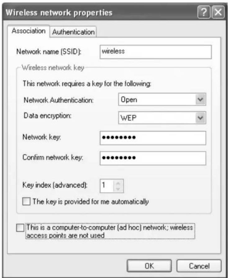
text_image
Wireless network properties Association Authentication Network name (SSID): wireless Wireless network key This network requires a key for the following: Network Authentication: Open Data encryption: WEP Network key: •••••••••• Confirm network key: •••••••••• Key index (advanced): 1 □ The key is provided for me automatically □ This is a computer-to-computer (ad hoc) network; wireless access points are not used OK Cancel4 From the Data encryption drop-down menu, select WEP.
5 If the wireless network does not require a network key, such as a password, go to step 9.
6 Click to uncheck the The key is provided for me automatically check box.
7 Enter the WEP network key in the Network key field.
8 Enter the WEP network key again in the Confirm network key field.
NOTE: Your computer can take up to 1 minute to connect to the network.
9 Click OK.
Your network setup is complete.
Connecting to a Network With Wi-Fi Protected Access (WPA) Security Requirements
The following instructions are basic steps for connecting to a WPA network. If your network requires a user name, password, or domain settings, consult the setup instructions in the user's guide for your wireless network card.
NOTE: WPA protocols require that you know the network authentication and data encryption settings for your wireless network. In addition, your WPA-protected network may require special settings such as a network key, user name, password, and domain name.
1 In the Preferred networks field, click the name of your wireless network.
2 Click Properties.
3 From the Network Authentication drop-down menu, select your network authentication type.
If you are using a WPA-protected network, and the Association tab does not give you the option to select WPA, download the WPA wireless security update from the Microsoft support site.
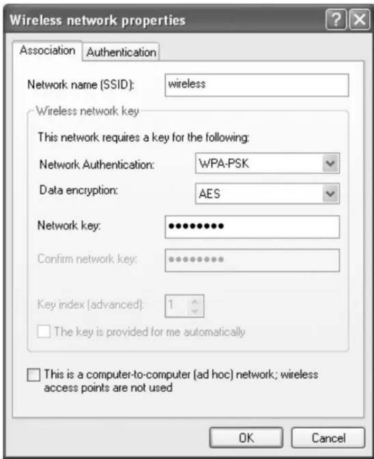
text_image
Wireless network properties Association Authentication Network name (SSID): wireless Wireless network key This network requires a key for the following: Network Authentication: WPA-PSK Data encryption: AES Network key: •••••••••• Confirm network key: ••••••••••• Key index (advanced): 1 □ The key is provided for me automatically □ This is a computer-to-computer (ad hoc) network; wireless access points are not used OK Cancel4 From the Data encryption drop-down menu, select your data encryption type.
5 If your wireless network requires a key, enter it in the Network key field.
NOTE: Your computer can take up to 1 minute to connect to the network.
6 Click OK.
Your network setup is complete.
Solving Problems
Using the Dell Diagnostics

CAUTION: Before you begin this procedure, read the safety instructions at the front of this document (see page 11).
When to Use the Dell Diagnostics
If you experience a problem with your computer, perform the checks in this chapter and run the Dell Diagnostics before you contact Dell for technical assistance.

NOTICE: The Dell Diagnostics works only on Dell™ computers.
The Dell Diagnostics is located on a hidden diagnostic utility partition on your hard drive.

NOTE: If your computer cannot display a screen image, contact Dell (see page 152).
1 Shut down the computer (see page 103).
2 Connect the computer to an electrical outlet.
3 Turn on the computer. When the DELL ^™ logo appears, press

NOTE: If you cannot see anything on your display, hold down the mute button and press the computer's power button to begin the Dell Diagnostics. The computer automatically runs the Pre-boot System Assessment.

NOTE: If you see a message stating that no diagnostics utility partition has been found, run the Dell Diagnostics from your Drivers and Utilities CD.
If you wait too long and the Microsoft ^® Windows ^® logo appears, continue to wait until you see the Windows desktop. Then shut down your computer through the Start menu and try again.
4 When the boot device list appears, highlight Diagnostics and press
The computer runs the Pre-boot System Assessment, a series of initial tests of your system board, keyboard, hard drive, and display.
- During the assessment, answer any questions that appear.
-
If a failure is detected, the computer stops and beeps. To stop the assessment and restart the computer, press
; to continue to the next test, press ; to retest the component that failed, press . -
If failures are detected during the Pre-boot System Assessment, write down the error code(s) and contact Dell (see page 152) before continuing on to the Dell Diagnostics.
- If the Pre-boot System Assessment completes successfully, you receive the message Booting Dell Diagnostic Utility Partition. Press any key to continue.
5 Press any key to start the Dell Diagnostics from the diagnostics utility partition on your hard drive.
6 When the Dell Diagnostics Main Menu appears, select the test you want to run, as described in the following section.
Dell Diagnostics Main Menu
1 After the Dell Diagnostics loads and the Main Menu screen appears, click the button for the option you want to run.
Option Function
| Express Test Performs a quick test of devices. This test typically takes 10 to 20 minutes and requires no interaction on your part. Run Express Test first to increase the possibility of tracing the problem quickly. |
| Extended Test Performs a thorough check of devices. This test typically takes an hour or more and requires you to answer questions periodically. |
| Custom Test Tests a specific device. You can customize the tests you want to run. |
| Symptom Tree Lists the most common symptoms encountered and allows you to select a test based on the symptom of the problem you are having. |
2 If a test detects a problem with a device, a message appears with an error code and a description of the problem. Write down the error code and problem description and follow the instructions on the screen.
If you cannot resolve the error condition, contact Dell (see "Contacting Dell" on page 152).

NOTE: The Service Tag for your computer is located at the top of each test screen. If you contact Dell, a technical support representative will ask for your Service Tag.
3 If you run a test from the Custom Test or Symptom Tree option, click the applicable tab described in the following table for more information.
Tab Function
| Results Displays the results of the test and any error conditions encountered. |
| Errors Displays error conditions encountered, error codes, and the problem description. |
| Help Describes the test and may indicate requirements for running the test. |
| Configuration Displays your hardware configuration for the selected device.The Dell Diagnostics obtains configuration information for all devices from the system setup program, memory, and various internal tests, and it displays the information in the device list in the left pane of the screen. The device list may not display the names of all the components installed on your computer or all devices attached to your computer. |
| Parameters Allows you to customize the test by changing the test settings. |
4 When the tests are complete, close the test screen to return to the Main Menu screen. To exit the Dell Diagnostics and restart the computer, close the Main Menu screen.
Error Messages
If the message is not listed, see the documentation for the operating system or the program that was running at the time the message appeared.
THE FILE BEING COPIED IS TOO LARGE FOR THE DESTINATION DRIVE — The file that you are trying to copy is too large to fit on the disk, or the disk is too full. Try copying the file to a different disk or use a larger capacity disk.
A FILENAME CANNOT CONTAIN ANY OF THE FOLLOWING CHARACTERS: \ / : * ? " < > | — Do not use these characters in filenames.
INSERT BOOTABLE MEDIA — The operating system is trying to boot to a nonbootable floppy disk or CD. Insert a bootable floppy disk or CD.
NON-SYSTEM DISK OR DISK ERROR — A floppy disk is in the floppy drive. Remove the floppy disk and restart the computer.
NTLDR IS MISSING — Essential system files are missing or corrupt. Use the following instructions to make new copies of the files from your Operating System CD:
1 Insert the Operating System CD and turn on your computer.
2 At the Welcome to Setup screen, press
3 When prompted for the particular Windows XP installation you want to log onto, press <1>.
4 In the next screen you will be prompted to enter the administrator password; enter the password if you have one. If no password is set, press
5 When c:\winnt>(or c:>) appears, type:copy x:\i386\ntdlr c:\
6 The message 1 file(s) copied appears.
7 Type copy x:\i386\ntdetect.com c:\ (where x: is the drive letter of your CD drive).
8 The message 1 file(s) copied appears.
9 Remove the Operating System CD and press to shut down and then restart the computer.
NOT ENOUGH MEMORY OR RESOURCES. EXIT SOME PROGRAMS AND TRY
AGAIN — You have too many programs open. Close all windows and open the program that you want to use.
OPERATING SYSTEM NOT FOUND — Contact Dell (see page 152).
A REQUIRED .DLL FILE WAS NOT FOUND — The program that you are trying to open is missing an essential file. Remove and then reinstall the program.
1 Click the Start button.
2 Click Control Panel.
3 Click Add or Remove Programs.
4 Select the program you want to remove.
5 Click Remove or Change/Remove and follow the prompts on the screen.
6 See the program documentation for installation instructions.
X:\ IS NOT ACCESSIBLE. THE DEVICE IS NOT READY — Insert a disk into the drive and try again.
Video and Display Problems
If the display is blank

NOTE: If you are using a program that requires a higher resolution than your computer supports, it is recommended that you attach an external monitor to your computer.
CHECK THE ⏻ LIGHT — When the ⏻ light is blinking, the computer has power.
- If the light is blinking, the computer is in standby mode—press the power button to exit standby mode.
- If the light is off, press the power button.
- If the light is on, your power management settings may have caused the display to turn off. Try pressing any key or move the cursor to exit standby mode.
CHECK THE BATTERY — If you are using a battery to power your computer, the battery charge may be depleted. Connect the computer to an electrical outlet using the AC adapter, and turn on the computer.
TEST THE ELECTRICAL OUTLET — Ensure that the electrical outlet is working by testing it with another device, such as a lamp.
CHECK THE AC ADAPTER — Check the AC adapter cable connections. If the AC adapter has a light, ensure that it is on.
CONNECT THE COMPUTER DIRECTLY TO AN ELECTRICAL OUTLET — Bypass power protection devices, power strips, and the extension cable to verify that the computer turns on.
ADJUST THE POWER PROPERTIES — Search for the keyword standby in the Windows Help and Support Center. To access the Help and Support Center, see page 19.
SWITCH THE VIDEO IMAGE — If your computer is attached to an external monitor, press
If the display is difficult to read
ADJUST THE BRIGHTNESS — See the Dell Inspiron Help file for instructions on adjusting the brightness. To access the help file, see page 18.
MOVE YOUR EXTERNAL SUBWOOFER AWAY FROM THE COMPUTER OR MONITOR — If your external speaker system includes a subwoofer, ensure that the subwoofer is at least 60 cm (2 ft) away from the computer or external monitor.
ELIMINATE POSSIBLE INTERFERENCE — Turn off nearby fans, fluorescent lights, halogen lamps, or other appliances.
ROTATE THE COMPUTER TO FACE A DIFFERENT DIRECTION — Eliminate sunlight glare, which can cause poor picture quality.
ADJUST THE WINDOWS DISPLAY SETTINGS
1 Click the Start button and then click Control Panel.
2 Click Appearance and Themes.
3 Click the area you want to change or click the Display icon.
4 Try different settings for Color quality and Screen resolution.
SEE "ERROR MESSAGES" — If an error message appears, see "Error Messages" on page 77.
If only part of the display is readable
CONNECT AN EXTERNAL MONITOR
1 Turn off your computer and connect an external monitor to the computer.
2 Turn on the computer and the monitor and adjust the monitor brightness and contrast controls.
If the external monitor works, the computer display or video controller may be defective. Contact Dell (see page 152).
Scanner Problems
CHECK THE POWER CABLE CONNECTION — Ensure that the scanner power cable is firmly connected to a working electrical power source and that the scanner is turned on.
CHECK THE SCANNER CABLE CONNECTION — Ensure that the scanner cable is firmly connected to the computer and to the scanner.
UNLOCK THE SCANNER — Ensure that your scanner is unlocked if it has a locking tab or button.
REINSTALL THE SCANNER DRIVER — See the scanner documentation for instructions.
Hard Drive Problems

NOTE: For information on saving files to a floppy disk, see the Dell Inspiron Help file. To access the help file, see page 18.
If you have problems with a hard drive
ALLOW THE COMPUTER TO COOL BEFORE TURNING IT ON — A hot hard drive may prevent the operating system from starting. Try allowing the computer to return to room temperature before turning it on.
CHECK THE DRIVE FOR ERRORS
1 Click the Start button and click My Computer.
2 Right-click the drive letter (local disk) that you want to scan for errors, and then click Properties.
3 Click the Tools tab.
4 Under Error-checking, click Check Now.
5 Click Start.
PC Card Problems
CHECK THE PC CARD — Ensure that the PC Card is properly inserted into the connector.
ENSURE THAT THE CARD IS RECOGNIZED BY WINDOWS® — Double-click the Unplug or Eject II Hardware icon in the Windows taskbar. Ensure that the card is listed.
IF YOU HAVE PROBLEMS WITH A DELL-PROVIDED PC CARD — Contact Dell (see page 152).
IF YOU HAVE PROBLEMS WITH A PC CARD NOT PROVIDED BY DELL—Contact the PC Card manufacturer.
External Keyboard Problems
NOTE: When you attach an external keyboard, the integrated keyboard remains fully functional.
CHECK THE KEYBOARD CABLE — Shut down the computer (see page 103). Disconnect the keyboard cable and check it for damage.
If you are using a keyboard extension cable, disconnect it and connect the keyboard directly to the computer.
CHECK THE EXTERNAL KEYBOARD
1 Turn off the computer, wait 1 minute, and turn it on again.
2 Verify that the numbers, capitals, and scroll lock lights on the keyboard blink during the boot routine.
3 From the Windows ^® desktop, click the Start button, point to Programs, point to Accessories, and click Notepad.
4 Type some characters on the external keyboard and verify that they appear on the display.
If you cannot verify these steps, you may have a defective external keyboard.
TO VERIFY THAT THE PROBLEM IS WITH THE EXTERNAL KEYBOARD, CHECK THE INTEGRATED KEYBOARD
1 Turn off the computer.
2 Disconnect the external keyboard.
3 Turn on the computer.
4 From the Windows desktop, click the Start button, point to Programs, point to Accessories, and click Notepad.
5 Type some characters on the external keyboard and verify that they appear on the display.
If the characters appear now but did not with the external keyboard, you may have a defective external keyboard. Contact Dell (see page 152).
Power Problems

NOTE: See the Dell Inspiron Help file for information on standby mode. To access the help file, see page 18.
CHECK THE POWER LIGHT — When the power light is lit or blinking, the computer has power. If the power light is blinking, the computer is in standby mode—press the power button to exit standby mode. If the light is off, press the power button to turn on the computer.
CHARGE THE BATTERY — The battery charge may be depleted.
1 Reinstall the battery.
2 Use the AC adapter to connect the computer to an electrical outlet.
3 Turn on the computer.
CHECK THE BATTERY STATUS LIGHT — If the battery status light flashes orange or is a steady orange the battery charge is low or depleted. Connect the computer to an electrical outlet.
If the battery status light flashes green and orange, the battery is too hot to charge. Turn off the computer, disconnect the computer from the electrical outlet, and then let the battery and computer cool to room temperature.
If the battery status light rapidly flashes orange, the battery may be defective. Contact Dell (see page 152).
TEST THE ELECTRICAL OUTLET — Ensure that the electrical outlet is working by testing it with another device, such as a lamp.
CHECK THE AC ADAPTER — Check the AC adapter cable connections. If the AC adapter has a light, ensure that the light is on.
CONNECT THE COMPUTER DIRECTLY TO AN ELECTRICAL OUTLET — Bypass power protection devices, power strips, and the extension cable to verify that the computer turns on.
ELIMINATE POSSIBLE INTERFERENCE — Turn off nearby fans, fluorescent lights, halogen lamps, or other appliances.
ADJUST THE POWER PROPERTIES — See the Dell Inspiron Help file or search for the keyword standby in the Windows Help and Support Center. To access help, see page 18.
RESEAT THE MEMORY MODULES — If the computer power light turns on but the display remains blank, reseat the memory modules. (For instructions, see "Memory" on page 105.)
Unexpected Characters
DISABLE THE NUMERIC KEYPAD — Press
Touch Pad or Mouse Problems
CHECK THE TOUCH PAD SETTINGS
1 Click the Start button, click Control Panel, and then click Printers and Other Hardware.
2 Click Mouse.
3 Try adjusting the settings.
CHECK THE MOUSE CABLE — Shut down the computer (see page 103).
Disconnect the mouse cable and check it for damage. Firmly reconnect the cable.
If you are using a mouse extension cable, disconnect it and connect the mouse directly to the computer.
TO VERIFY THAT THE PROBLEM IS WITH THE MOUSE, CHECK THE TOUCH PAD
1 Turn off the computer.
2 Disconnect the mouse.
3 Turn on the computer.
4 At the Windows desktop, use the touch pad to move the cursor around, select an icon, and open it.
If the touch pad operates correctly, the mouse may be defective.
REINSTALL THE TOUCH PAD DRIVER — See "Reinstalling Drivers and Utilities" on page 94.
Printer Problems
CHECK THE PRINTER CABLE CONNECTIONS — Ensure that the printer cable is properly connected to the computer.
TEST THE ELECTRICAL OUTLET — Ensure that the electrical outlet is working by testing it with another device, such as a lamp.
ENSURE THAT THE PRINTER IS TURNED ON — See the documentation supplied with the printer.
VERIFY THAT WINDOWS® RECOGNIZES THE PRINTER
1 Click the Start button.
2 Click Control Panel.
3 Click Printers and Other Hardware.
4 Click View installed printers or fax printers. If the printer model is listed, right-click the printer icon.
5 Click Properties, and then click the Ports tab. Ensure that the Print to the following port(s): setting is USB.
REINSTALL THE PRINTER DRIVER — See the documentation supplied with the printer.
E-Mail Problems
ENSURE THAT YOU ARE CONNECTED TO THE INTERNET — With the Outlook Express e-mail program open, click File. If Work Offline has a check mark next to it, click the check mark to remove it and connect to the Internet.
Modem and Internet Connection Problems
NOTICE: Connect the modem to an analog telephone wall jack only. Connecting the modem to a digital telephone network damages the modem.
NOTICE: Modem and network connectors look similar. Do not plug a telephone line into the network connector.
NOTE: If you can connect to your Internet service provider (ISP), your modem is functioning properly. If you are sure that your modem is working properly and you still experience problems, contact your ISP.
CHECK THE TELEPHONE WALL JACK — Disconnect the telephone line from the modem and connect it to a telephone. Listen for a dial tone. Ensure that you have touchtone telephone service. Try connecting the modem to a different telephone wall jack.
Slow connection speeds can be caused by telephone noise as well as by telephone line or network conditions. Contact your telephone company or network administrator for more information.
CONNECT THE MODEM CABLE DIRECTLY TO THE TELEPHONE WALL JACK — If you have other telephone devices sharing the line, such as an answering machine, fax machine, surge protector, or line splitter, then bypass them and use the telephone line to connect the modem directly to the telephone wall jack.
CHECK THE CONNECTION — Verify that the telephone line is connected to the modem.
CHECK THE TELEPHONE LINE — Try using a different telephone line. If you are using a line that is 3 m (10 ft) or more in length, try a shorter one.
IRREGULAR DIAL TONE — If you have voice mail service, you might hear an irregular dial tone when you have messages. Contact your telephone company for instructions on restoring a dial tone.
TURN OFF CALL WAITING (CATCH-PHONE) — See your telephone directory for instructions on deactivating this feature. Then adjust the dial-up networking connection properties.
1 Click the Start button and click Control Panel.
2 Click Printers and Other Hardware, click Phone and Modem Options, click the Dialing Rules tab, and then click Edit....
3 In the Edit Location window, ensure that To disable call waiting, dial: is checked, and then select the proper code as listed in your telephone directory.
4 Click Apply and click OK.
5 Close the Phone and Modems Options window.
6 Close the Control Panel window.
VERIFY THAT THE MODEM IS COMMUNICATING WITH WINDOWS
1 Click the Start button and click Control Panel.
2 Click Printers and Other Hardware and click Phone and Modem Options.
3 Click the Modems tab.
4 Click the COM port for your modem.
5 Click Properties, click the Diagnostics tab, and then click Query Modem to verify that the modem is communicating with Windows.
If all commands receive responses, the modem is operating properly.
Network Problems
CHECK THE NETWORK CABLE CONNECTOR — Ensure that the network cable connector is firmly connected to the optional connector on the computer and the network wall jack.
CHECK THE NETWORK LIGHTS ON THE NETWORK CONNECTOR —
Green indicates that the network connection is active. If the status light is not green, try replacing the network cable. Amber indicates that the optional network adapter driver is loaded and the adapter is detecting activity.
RESTART THE COMPUTER — Try to log on to the network again.
CONTACT YOUR NETWORK ADMINISTRATOR — Verify that your network settings are correct and that the network is functioning.
General Program Problems
A program crashes
NOTE: Software usually includes installation instructions in its documentation or on a floppy disk or CD.
SEE THE SOFTWARE DOCUMENTATION — Many software manufacturers maintain websites with information that may help you solve the problem. Ensure that you properly installed and configured the program. Reinstall the program if necessary.
A program stops responding
END THE PROGRAM
1 Simultaneously press
2 Click the Applications tab, and then select the program that is no longer responding.
3 Click End Task.
A solid blue screen appears
TURN THE COMPUTER OFF — If the computer does not respond to a keystroke or a proper shutdown (see page 103), press the power button until the computer turns off. Press the power button again to restart the computer. The solid blue screen appears because you were not able to perform a proper Windows ^® shutdown. ScanDisk automatically runs during the start-up process. Follow the instructions on the screen.
Error messages appear
REVIEW "ERROR MESSAGES" — Look up the message and take the appropriate action. See the software documentation.
CD or DVD Problems
If you cannot play a CD, CD-RW, or DVD
NOTE: Because of different worldwide file types, not all DVD titles work in all DVD drives.
High-speed CD drive vibration is normal and may cause noise. This noise does not indicate a defect with the drive or the CD.
ENSURE THAT WINDOWS® RECOGNIZES THE DRIVE — Click the Start button and click My Computer, or right-click the Start button and click Explorer. If the drive is not listed, perform a full scan with your antivirus software to check for and remove viruses. Viruses can sometimes prevent Windows from recognizing the drive. Insert a bootable disk and restart the computer. Verify that the light is blinking, indicating normal operation.
TRY ANOTHER DISC — Insert another disc to eliminate the possibility that the original disc is defective.
ADJUST THE WINDOWS VOLUME CONTROL — Double-click the speaker icon in the lower-right corner of your screen. Ensure that the volume is turned up and that the sound is not muted.
REINSTALL THE DRIVE
1 Save and close any open files, exit any open programs, and shut down the computer (see page 103).
2 Remove the drive. See "Using the Module Bay" on page 55 for instructions.
3 Reinstall the drive.
4 Turn on the computer.
CLEAN THE DRIVE OR DISC — See "Cleaning Your Computer" in the Dell Inspiron Help file for instructions. To access the help file, see page 18.
If you cannot eject the CD, CD-RW, or DVD drive tray
1 Ensure that the computer is turned off.
2 Straighten a paper clip and insert one end into the eject hole at the front of the drive; push firmly until the tray is partially ejected.
3 Gently pull out the tray until it stops.
If you hear an unfamiliar scraping or grinding sound
- Ensure that the sound is not caused by the program that is running.
- Ensure that the disk or disc is inserted properly.
If the CD-RW drive stops writing
DISABLE STANDBY MODE IN WINDOWS BEFORE WRITING TO A CD-RW — Search for the keyword standby in the Windows Help and Support Center. To access the Help and Support Center, see page 19.
CHANGE THE WRITE SPEED TO A SLOWER RATE — See the help files for your CD creation software.
EXIT ALL OTHER OPEN PROGRAMS — Exiting all other open programs before writing to the CD-RW may alleviate the problem.
Sound and Speaker Problems
If you have a problem with integrated speakers
ADJUST THE WINDOWS® VOLUME CONTROL — Double-click the speaker icon in the lower-right corner of your screen. Ensure that the volume is turned up and that the sound is not muted.
ADJUST THE VOLUME USING KEYBOARD SHORTCUTS — Press
REINSTALL THE SOUND (AUDIO) DRIVER — See "Reinstalling Drivers and Utilities" on page 94.
If you have a problem with external speakers

NOTE: The volume control in some MP3 players overrides the Windows volume setting. If you have been listening to MP3 songs, make sure that you did not turn the player volume down or off.
CHECK THE SPEAKER CABLE CONNECTIONS — See the setup diagram supplied with the speakers.
TEST THE ELECTRICAL OUTLET — Ensure that the electrical outlet is working by testing it with another device, such as a lamp.
ENSURE THAT THE SPEAKERS ARE TURNED ON — See the setup diagram supplied with the speakers.
ADJUST THE WINDOWS VOLUME CONTROL — Double-click the speaker icon in the lower-right corner of your screen. Ensure that the volume is turned up and that the sound is not muted. Adjust the volume, bass, or treble controls to eliminate distortion.
TEST THE SPEAKERS — Plug the speaker audio cable into the line-out connector on the computer. Ensure that the headphone volume control is turned up. Play a music CD.
RUN THE SPEAKER SELF-TEST — Some speaker systems have a self-test button on the subwoofer. See the speaker documentation for self-test instructions.
ELIMINATE POSSIBLE INTERFERENCE — Turn off nearby fans, fluorescent lights, or halogen lamps to check for interference.
REINSTALL THE SOUND (AUDIO) DRIVER — See "Reinstalling Drivers and Utilities" on page 94.
E-Mail, Modem, and Internet Problems

CAUTION: Before you begin any of the procedures in this section, follow the safety instructions in the Product Information Guide.

NOTE: Connect the modem to an analog telephone jack only. The modem does not operate while it is connected to a digital telephone network.
CHECK THE MICROSOFT OUTLOOK® EXPRESS SECURITY SETTINGS — If you cannot open your e-mail attachments:
1 In Outlook Express, click Tools, click Options, and then click Security.
2 Click Do not allow attachments to remove the checkmark.
CHECK THE TELEPHONE LINE CONNECTION —
CHECK THE TELEPHONE JACK —
CONNECT THE MODEM DIRECTLY TO THE TELEPHONE WALL JACK —
USE A DIFFERENT TELEPHONE LINE —
- Verify that the telephone line is connected to the jack on the modem. (The jack has either a green label or a connector-shaped icon next to it.)
- Ensure that you hear a click when you insert the telephone line connector into the modem.
- Disconnect the telephone line from the modem and connect it to a telephone. Listen for a dial tone.
- If you have other telephone devices sharing the line, such as an answering machine, fax machine, surge protector, or line splitter, then bypass them and use the telephone to connect the modem directly to the telephone wall jack. If you are using a line that is 3 m (10 ft) or more in length, try a shorter one.
RUN THE MODEM HELPER DIAGNOSTICS — Click the Start button, point to All Programs, and then click Modem Helper. Follow the instructions on the screen to identify and resolve modem problems.
(Modem Helper is not available on all computers.)
VERIFY THAT THE MODEM IS COMMUNICATING WITH WINDOWS —
1 Click the Start button and click Control Panel
2 Click Printers and Other Hardware.
3 Click Phone and Modem Options.
4 Click the Modems tab.
5 Click the COM port for your modem.
6 Click Properties, click the Diagnostics tab, and then click Query Modem to verify that the modem is communicating with Windows.
If all commands receive responses, the modem is operating properly.
ENSURE THAT YOU ARE CONNECTED TO THE INTERNET — Ensure that you have subscribed to an Internet provider. With the Outlook Express e-mail program open, click File. If Work Offline has a checkmark next to it, click the checkmark to remove it and connect to the Internet. For help, contact your Internet service provider.
SCAN THE COMPUTER FOR SPYWARE — If you are experiencing slow computer performance, you frequently receive pop-up advertisements, or you are having problems connecting to the Internet, your computer might be infected with spyware. Use an anti-virus program that includes anti-spyware protection (your program may require an upgrade) to scan the computer and remove spyware. For more information, go to support.dell.com and search for the keyword spyware.
Resolving Other Technical Problems
GO TO THE DELL SUPPORT WEBSITE — Go to support.dell.com for help with general usage, installation, and troubleshooting questions. See "Dell Technical Support Policy (U.S. Only)" on page 152 for a description of the hardware and software support provided by Dell.
E-MAIL DELL — Go to support.dell.com and then click E-Mail Dell in the Communicate list. Send an e-mail message to Dell about your problem; you can expect to receive an e-mail message from Dell within hours. See "Dell Technical Support Policy (U.S. Only)" on page 152 for a description of the hardware and software support provided by Dell.
CONTACT DELL — If you cannot solve your problem using the Dell™ support website or e-mail service, call Dell for technical assistance (see page 152). See "Dell Technical Support Policy (U.S. Only)" on page 152 for a description of the hardware and software support provided by Dell.
Drivers
What Is a Driver?
A driver is a program that controls a device such as a printer, mouse, or keyboard. All devices require a driver program. A driver acts like a translator between the device and any other programs that use the device. Each device has its own set of specialized commands that only its driver recognizes.
Dell ships your computer to you with required drivers already installed—no further installation or configuration is needed.

NOTICE: The Drivers and Utilities CD may contain drivers for operating systems that are not on your computer. Ensure that you are installing software appropriate for your operating system.
Many drivers, such as the keyboard driver, come with your Microsoft ^® Windows ^® operating system. You may need to install drivers if you:
- Upgrade your operating system.
- Reinstall your operating system.
- Connect or install a new device.
Identifying Drivers
If you experience a problem with any device, identify whether the driver is the source of your problem and, if necessary, update the driver.
1 Click the Start button and click Control Panel
2 Under Pick a Category, click Performance and Maintenance.
3 Click System.
4 In the System Properties window, click the Hardware tab.
5 Click Device Manager.
6 Scroll down the list to see if any device has an exclamation point (a yellow circle with a [!]) on the device icon.
If an exclamation point is next to the device name, you may need to reinstall the driver or install a new driver as described in the following section.
Reinstalling Drivers and Utilities

NOTICE: The Dell Support website at support.dell.com and your Drivers and Utilities CD provide approved drivers for Dell™ computers. If you install drivers obtained from other sources, your computer might not work correctly.
Using Windows XP Device Driver Rollback
If a problem occurs on your computer after you install or update a driver, use Windows XP Device Driver Rollback to replace the driver with the previously installed version.
1 Click the Start button and click Control Panel
2 Under Pick a Category, click Performance and Maintenance.
3 Click System.
4 In the System Properties window, click the Hardware tab.
5 Click Device Manager.
6 Right-click the device for which the new driver was installed and click Properties.
7 Click the Drivers tab.
8 Click Roll Back Driver.
If Device Driver Rollback does not resolve the problem, then use System Restore (see page 97) to return your computer to the operating state that existed before you installed the new driver.
Using the Drivers and Utilities CD
If using Device Driver Rollback or System Restore does not resolve the problem, then reinstall the driver from the Drivers and Utilities CD.
1 Save and close any open files, and exit any open programs.
2 Insert the Drivers and Utilities CD.
In most cases, the CD starts running automatically. If it does not, start Windows Explorer, click your CD drive directory to display the CD contents, and then double-click the autorcd.exe file. The first time that you run the CD, it might prompt you to install setup files. Click OK, and follow the instructions on the screen to continue.
3 From the Language drop-down menu in the toolbar, select your preferred language for the driver or utility (if available). A welcome screen appears.
4 Click Next.
The CD automatically scans your hardware to detect drivers and utilities used by your computer.
5 After the CD completes the hardware scan, you can also detect other drivers and utilities.
Under Search Criteria, select the appropriate categories from the System Model, Operating System, and Topic drop-down menus.
A link or links appear(s) for the specific drivers and utilities used by your computer.
6 Click the link of a specific driver or utility to display information about the driver or utility that you want to install.
7 Click the Install button (if present) to begin installing the driver or utility. At the welcome screen, follow the screen prompts to complete the installation.
If no Install button is present, automatic installation is not an option. For installation instructions, either see the appropriate instructions in the following sections, or click Extract, follow the extracting instructions, and then read the readme file.
If instructed to navigate to the driver files, click the CD directory on the driver information window to display the files associated with that driver.
Manually Reinstalling Drivers
NOTE: If you are reinstalling an infrared sensor driver, you must first enable the infrared sensor (see page 151) in the system setup program before continuing with the driver installation.
1 After extracting the driver files to your hard drive as described in the previous section, click the Start button and right-click My Computer.
2 Click Properties.
3 Click the Hardware tab and click Device Manager.
4 Double-click the type of device for which you are installing the driver (for example, Modems or Infrared devices).
5 Double-click the name of the device for which you are installing the driver.
6 Click the Driver tab and click Update Driver.
7 Click Install from a list or specific location (Advanced) and click Next.
8 Click Browse and browse to the location to which you previously extracted the driver files.
9 When the name of the appropriate driver appears, click Next.
10 Click Finish and restart your computer.
Resolving Software and Hardware Incompatibilities
If a device is either not detected during the operating system setup or is detected but incorrectly configured, you can use Device Manager or the Hardware Troubleshooter to resolve the incompatibility.
To resolve incompatibilities using Device Manager:
1 Click the Start button and click Control Panel
2 Click Performance and Maintenance and click System.
3 Click the Hardware tab and click Device Manager.
4 In the Device Manager list, check for devices that are incorrectly configured.
Incorrectly configured devices are indicated by a yellow exclamation point (!) or a red x if the device has been disabled.
5 Double-click any device marked with an exclamation point to display the Propertieswindow. The Device status area in the Properties window reports the cards or devices that need to be reconfigured.
6 Reconfigure the devices or remove the devices from the Device Manager. See the documentation that came with the device for information on configuring the device.
To resolve incompatibilities using the Hardware Troubleshooter:
1 Click the Start button and click Help and Support.
2 Type hardware troubleshooter in the Search field and click the arrow to start the search.
3 Click Hardware Troubleshooter in the Search Results list.
4 In the Hardware Troubleshooter list, click I need to resolve a hardware conflict on my computer, and click Next.
Using Microsoft® Windows® XP System Restore
The Microsoft Windows XP operating system provides System Restore to allow you to return your computer to an earlier operating state (without affecting data files) if changes to the hardware, software, or other system settings have left the computer in an undesirable operating state. See the Windows Help and Support Center for information on using System Restore. To access the Help and Support Center, see page 19.

NOTICE: Make regular backups of your data files. System Restore does not monitor your data files or recover them.
Creating a Restore Point
1 Click the Start button and click Help and Support.
2 Click System Restore.
3 Follow the instructions on the screen.
Restoring the Computer to an Earlier Operating State
If problems occur after you install a device driver, use Device Driver Rollback (see page 94) to resolve the problem. If that is unsuccessful, then use System Restore.

NOTICE: Before you restore the computer to an earlier operating state, save and close any open files and exit any open programs. Do not alter, open, or delete any files or programs until the system restoration is complete.
1 Click the Start button, point to All Programs → Accessories → System Tools, and then click System Restore
2 Ensure that Restore my computer to an earlier time is selected and click Next.
3 Click a calendar date to which you want to restore your computer.
The Select a Restore Point screen provides a calendar that allows you to see and select restore points. All calendar dates with available restore points appear in boldface type.
4 Select a restore point and click Next.
If a calendar date has only one restore point, then that restore point is automatically selected. If two or more restore points are available, click the restore point that you prefer.
5 Click Next.
The Restoration Complete screen appears after System Restore finishes collecting data and then the computer restarts.
6 After the computer restarts, click OK.
To change the restore point, you can either repeat the steps using a different restore point, or you can undo the restoration.
Undoing the Last System Restore
NOTICE: Before you undo the last system restore, save and close all open files and exit any open programs. Do not alter, open, or delete any files or programs until the system restoration is complete.
1 Click the Start button, point to All Programs → Accessories → System Tools, and then click System Restore.
2 Click Undo my last restoration and click Next.
3 Click Next.
The System Restore screen appears and the computer restarts.
4 After the computer restarts, click OK.
Enabling System Restore
If you reinstall Windows XP with less than 200 MB of free hard-disk space available, System Restore is automatically disabled. To see if System Restore is enabled:
1 Click the Start button and click Control Panel.
2 Click Performance and Maintenance.
3 Click System.
4 Click the System Restore tab.
5 Ensure that Turn off System Restore is unchecked.
Reinstalling Microsoft ^® Windows ^® XP
Before You Begin
If you are considering reinstalling the Windows XP operating system to correct a problem with a newly installed driver, first try using Windows XP Device Driver Rollback (see page 94). If Device Driver Rollback does not resolve the problem, then use System Restore (see page 97) to return your operating system to the operating state it was in before you installed the new device driver.

NOTICE: Before performing the installation, back up all data files on your primary hard drive. For conventional hard drive configurations, the primary hard drive is the first drive detected by the computer.
To reinstall Windows XP, you need the following items:
• D c Operating System CD
• D Driversland Utilities CD

NOTE: The Drivers and Utilities CD contains drivers that were installed during assembly of the computer. Use the Drivers and Utilities CD to load any required drivers.
Reinstalling Windows XP
To reinstall Windows XP, perform all the steps in the following sections in the order in which they are listed.
The reinstallation process can take 1 to 2 hours to complete. After you reinstall the operating system, you must also reinstall the device drivers (see "Reinstalling Drivers and Utilities" on page 94), virus protection program, and other software.

NOTICE: The Operating System CD provides options for reinstalling Windows XP. The options can overwrite files and possibly affect programs installed on your hard drive. Therefore, do not reinstall Windows XP unless a Dell technical support representative instructs you to do so.

NOTICE: To prevent conflicts with Windows XP, disable any virus protection software installed on your computer before you reinstall Windows XP. See the documentation that came with the software for instructions.
Booting From the Operating System CD
1 Save and close any open files and exit any open programs.
2 Insert the Operating System CD. Click Exit if the Install Windows XP message appears.
3 Restart the computer.
4 Press
If the operating system logo appears, wait until you see the Windows desktop, and then shut down the computer and try again.
5 Press the arrow keys to select CD-ROM, and press
6 When the Press any key to boot from CD message appears, press any key.
Windows XP Setup
1 When the Windows XP Setup screen appears, press
2 Read the information on the Microsoft Windows Licensing Agreement screen, and press
3 If your computer already has Windows XP installed and you want to recover your current Windows XP data, type r to select the repair option, and remove the CD.
4 If you want to install a new copy of Windows XP, press
5 Press
The Windows XP Setup screen appears, and the operating system begins to copy files and install the devices. The computer automatically restarts multiple times.

NOTICE: Do not press any key when the following message appears: Press any key to boot from the CD.

NOTE: The time required to complete the setup depends on the size of the hard drive and the speed of your computer.
6 When the Regional and Language Options screen appears, select the settings for your location and click Next.
7 Enter your name and organization (optional) in the Personalize Your Softwarescreen, and click Next.
8 If you are reinstalling Windows XP I Home Edition, at the What's your computer's name window, enter a name for your computer (or accept the name provided) and click Next.
If you are reinstalling Windows XP Professional, at the Computer Name and Administrator Password window, enter a name for your computer (or accept the one provided) and a password, and click Next.
9 If the Modem Dialing Information screen appears, enter the requested information and click Next
10 Enter the date, time, and time zone in the Date and Time Settings window, and clickNext.
11 If the Networking Settings screen appears, click Typical and click Next.
12 If you are reinstalling Windows XP Professional and you are prompted to provide further information regarding your network configuration, enter your selections. If you are unsure of your settings, accept the default selections.
Windows XP installs the operating system components and configures the computer. The computer automatically restarts.

NOTICE: Do not press any key when the following message appears: Press any key to boot from the CD.
13 When the Welcome to Microsoft screen appears, click Next.
14 When the How will this computer connect to the Internet? message appears, click Skip.
15 When the Ready to register with Microsoft? screen appears, select No, not at this time and click Next.
16 When the Who will use this computer? screen appears, you can enter up to five users.
17 Click Next.
18 Click Finish to complete the setup, and remove the CD.
19 Reinstall the appropriate drivers with the Drivers and Utilities CD. For instructions, see "Reinstalling Drivers and Utilities" on page 94.
20 Reinstall your virus protection software.
21 Reinstall your programs.

NOTE: To reinstall and activate your Microsoft Office or Microsoft Works Suite programs, you need the Product Key number located on the back of the Microsoft Office or Microsoft Works Suite CD sleeve.
Adding and Replacing Parts
Before You Begin
This chapter provides procedures for removing and installing the components in your computer. Unless otherwise noted, each procedure assumes that the following conditions exist:
- You have performed the steps in "Shutting Down Your Computer" (see page 103).
- You have read the safety information (see page 11).

NOTE: Unless otherwise noted, each procedure in this chapter assumes that a part can be replaced by performing the removal procedure in the reverse order.
Recommended Tools
The procedures in this chapter may require the following tools:
- Small flat-blade screwdriver
- Phillips screwdriver
- Small plastic scribe
- Flash BIOS update program floppy disk or CD
Shutting Down Your Computer
Use the following safety guidelines to help protect your computer from potential damage and to help ensure your own personal safety.

CAUTION: Before you begin this procedure, read the safety instructions at the front of this document (see page 11).

CAUTION: Handle components and cards with care. Do not touch the components or contacts on a card. Hold a card by its edges or by its metal mounting bracket. Hold a component such as a memory module by its side edges, not by its connector edge.

NOTICE: Only a certified service technician should perform repairs on your computer. Damage due to servicing that is not authorized by Dell is not covered by your warranty.

NOTICE: When you disconnect a cable, pull on its connector or on its strain-relief loop, not on the cable itself. Some cables have a connector with locking tabs; if you are disconnecting this type of cable, press in on the locking tabs before you disconnect the cable. As you pull connectors apart, keep them evenly aligned to avoid bending any connector pins. Also, before you connect a cable, ensure that both connectors are correctly oriented and aligned.
NOTICE: To avoid damaging the computer, perform the following steps before you begin working inside the computer.
1 Ensure that the work surface is flat and clean to prevent the computer cover from being scratched.
2 Shut down the computer (see page 103).
3 Ensure that the computer and any attached devices are turned off. If your computer and attached devices did not automatically turn off when you shut down your computer, press and hold the power button for 4 seconds.
NOTICE: To disconnect a network cable, first unplug the cable from your computer and then unplug it from the network wall jack.
4 Disconnect any telephone or telecommunication lines from the computer.
5 Disconnect your computer and all attached devices from their electrical outlets, and then press the power button to ground the system board.
NOTICE: To connect a network cable, first plug the cable into the network wall jack and then plug it into the computer.
6 Remove any installed PC Cards from the PC Card slot.
7 Close the display and turn the computer upside down on a flat work surface.
NOTICE: To avoid damaging the system board, you must remove the main battery before you begin working inside the computer.
8 Slide and hold the battery-bay latch release on the bottom of the computer, and then remove the battery from the bay.
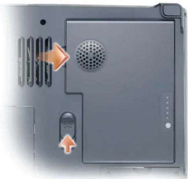
natural_image
Close-up of a laptop's front panel showing ventilation slots, a perforated vent, and a speaker grille (no text or symbols visible)9 Remove any installed module from the module bay.
10 Remove the hard drive (see page 111).
Memory
You can increase your computer memory by installing memory modules on the system board. See "Specifications" on page 144 for information on the memory supported by your computer. Install only memory modules that are intended for your computer.

CAUTION: Before you begin this procedure, read the safety instructions at the front of this document (see page 11).

NOTICE: To avoid damaging the system board, you must remove the main battery before you begin working inside the computer (see page 52).

NOTE: Memory modules purchased from Dell are covered under your computer warranty.

NOTE: This computer requires matched memory modules and therefore always has two identical memory modules.
1 Follow the procedures in "Before You Begin" (see page 103).
2 Turn the computer over, unscrew the captive screw labeled "M", and remove the memory module cover.
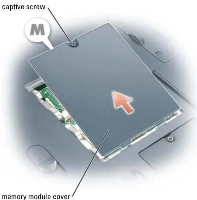
text_image
captive screw memory module coverNOTICE: To prevent damage to the memory module connector, do not use tools to spread the memory-module securing clips.
3 If you are replacing a memory module, ground yourself and remove the existing module:
a Use your fingertips to carefully spread apart the securing clips on each end of the memory module connector until the module pops up.
b Remove the module from the connector at a 45-degree angle.
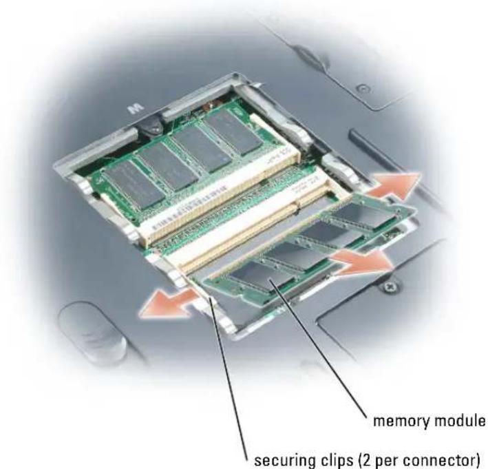
text_image
memory module securing clips (2 per connector)NOTICE: Ensure that memory modules are installed in both connectors and they are of the same capacity. Insert memory modules at a 45-degree angle to avoid damaging the connector.
4 Ground yourself and install the new memory module:
NOTE: If the memory module is not installed properly, the computer may not boot properly. No error message indicates this failure.
a Align the notch in the module edge connector with the tab in the connector slot.
b Slide the module firmly into the slot at a 45-degree angle, and rotate the module down until it clicks into place. If you do not feel the click, remove the module and reinstall it.
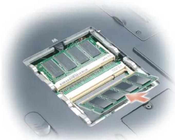
natural_image
Internal view of a computer processor showing internal RAM chips and an open circuit board (no text or symbols visible)5 Replace the memory module cover.

NOTICE: If the cover is difficult to close, remove the module and reinstall it. Forcing the cover to close may damage your computer.
6 Insert the battery into the battery bay, or connect the AC adapter to your computer and an electrical outlet.
7 Turn on the computer.
As the computer boots, it detects the additional memory and automatically updates the system configuration information.
To confirm the amount of memory installed in the computer, click the Start button, click Help and Support, and then click Computer Information.
Mini PCI Card
CAUTION: FCC rules strictly prohibit users from installing 5-GHz (802.11a,802.11a/b, 802.11a/b/g) Wireless LAN Mini PCI cards. Under no circumstances should you install such a device. Only trained Dell service personnel are authorized to install a 5-GHz Wireless LAN Mini PCI card.
CAUTION: If you are removing and/or installing a 2.4-GHz (802.11b, 802.11b/g) Mini PCI card, follow the instructions noted below. Only products approved for use in your portable computer may be installed. Approved Mini PCI cards may be purchased only from Dell.
CAUTION: Before you begin this procedure, read the safety instructions at the front of this document (see page 11).
NOTICE: To avoid damaging the system board, you must remove the main battery before you begin working inside the computer (see page 52).
NOTE: 2.4-GHz Wireless LAN PC Cards may be removed and installed by the user.
If you ordered a Mini PCI card with your computer, the card is already installed.
1 Follow the procedures in "Before You Begin" (see page 103).
2 Turn the computer over.
3 Unscrew the captive screw labeled "C" and remove the Mini PCI card cover.
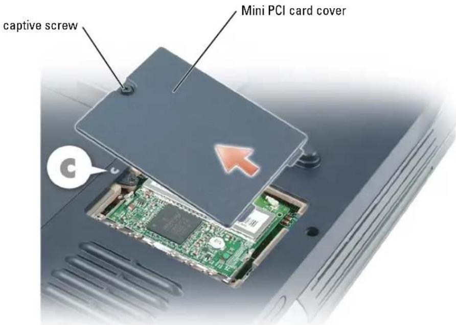
text_image
captive screw Mini PCI card cover4 If a Mini PCI card is not already installed, go to step 5. If you are replacing a Mini PCI card, first remove the existing card:
a Disconnect the antenna cables from the Mini PCI card.
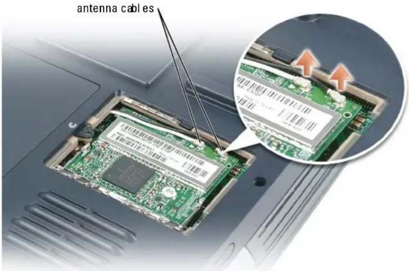
text_image
antenna cablesb Release the Mini PCI card by spreading the metal securing tabs until the card pops up slightly.
c Lift the Mini PCI card out of its connector.
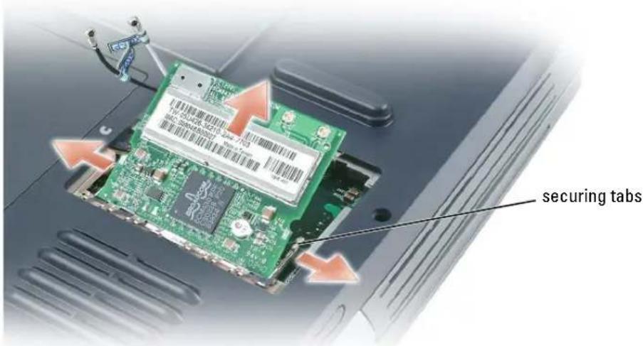
text_image
securing tabsNOTICE: The connectors are keyed to ensure correct insertion. If you feel resistance, check the connectors and realign the card.
5 To install a Mini PCI card, align the card with the connector at a 45-degree angle, and press the card into the connector until it clicks.
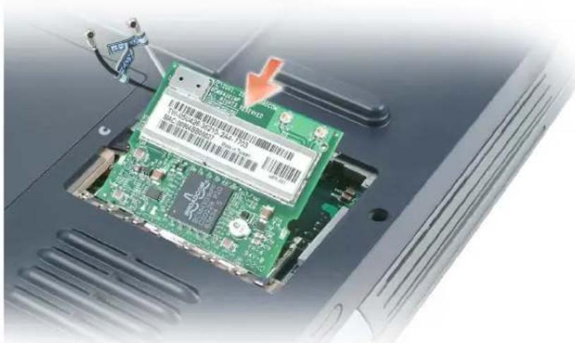
natural_image
Laptop CPU socket with green circuit board and a red arrow pointing to a component (no visible text or symbols)NOTICE: To avoid damaging the antenna cables or the Mini PCI card, never place the cables under the card.
6 Connect the antenna cables to the Mini PCI card.
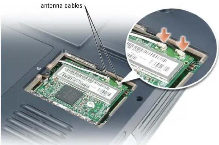
text_image
antenna cables7 Replace the Mini PCI card cover and tighten the captive screw.
Hard Drive

CAUTION: If you remove the hard drive from the computer when the drive is hot, do not touch the metal housing of the hard drive.

CAUTION: Before you begin this procedure, read the safety instructions at the front of this document (see page 11).

NOTICE: To avoid damaging the system board, you must remove the main battery before you begin working inside the computer.

NOTICE: To prevent data loss, turn off your computer before removing the hard drive. Do not remove the hard drive while the computer is on, in standby mode, or in hibernate mode.

NOTICE: Hard drives are extremely fragile; even a slight bump can damage the drive.

NOTE: Dell does not guarantee compatibility or provide support for hard drives from sources other than Dell.

NOTE: You need the Operating System CD to install the Microsoft® Windows® operating system. You also need the Drivers and Utilities CD for your computer to install the drivers and utilities on the new hard drive.
To replace the hard drive in the hard drive bay:
1 Follow the procedures in "Before You Begin" (see page 103).
2 Turn the computer over, and remove the hard drive screw.
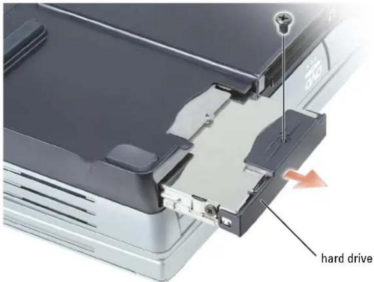
text_image
hard driveNOTICE: When the hard drive is not in the computer, store it in protective antistatic packaging. See "Protecting Against Electrostatic Discharge" on page 14.
3 Slide the hard drive out of the computer.
4 Remove the new drive from its packaging. Save the original packaging for storing or shipping the hard drive.
NOTICE: Use firm and even pressure to slide the drive into place. If you use excessive force, you may damage the connector.
5 Slide the drive into the bay until it is fully seated.
6 Replace and tighten the screw.
7 Use the Operating System CD to install the operating system for your computer. For instructions, see "Reinstalling Microsoft Windows XP" on page 98.
8 Use the Drivers and Utilities CD to install the drivers and utilities for your computer. For instructions, see "Reinstalling Drivers and Utilities" on page 94.
Returning a Hard Drive to Dell
Return your old hard drive to Dell in its original or comparable foam packaging. Otherwise, the hard drive may be damaged in transit.
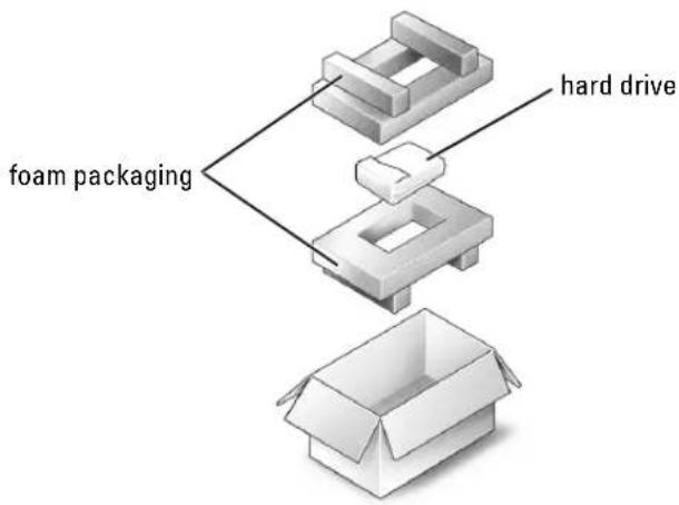
flowchart
graph TD
    A["foam packaging"] --> B["hard drive"]
    B --> C["open box"]
Subwoofer

CAUTION: Before you begin this procedure, read the safety instructions at the front of this document (see page 11).

NOTICE: To avoid electrostatic discharge, ground yourself by using a wrist grounding strap or by periodically touching a connector on the back panel of the computer.
If you ordered a subwoofer with your computer, it is already installed. To remove and replace a subwoofer:
1 Follow the procedures in "Before You Begin" (see page 103).
2 Remove the battery (see page 52).
3 Remove the subwoofer from the battery:
a Disconnect the subwoofer cable.
b Apply a small screwdriver or scribe to the notch in the side of the battery, releasing the subwoofer from the compartment in the battery.
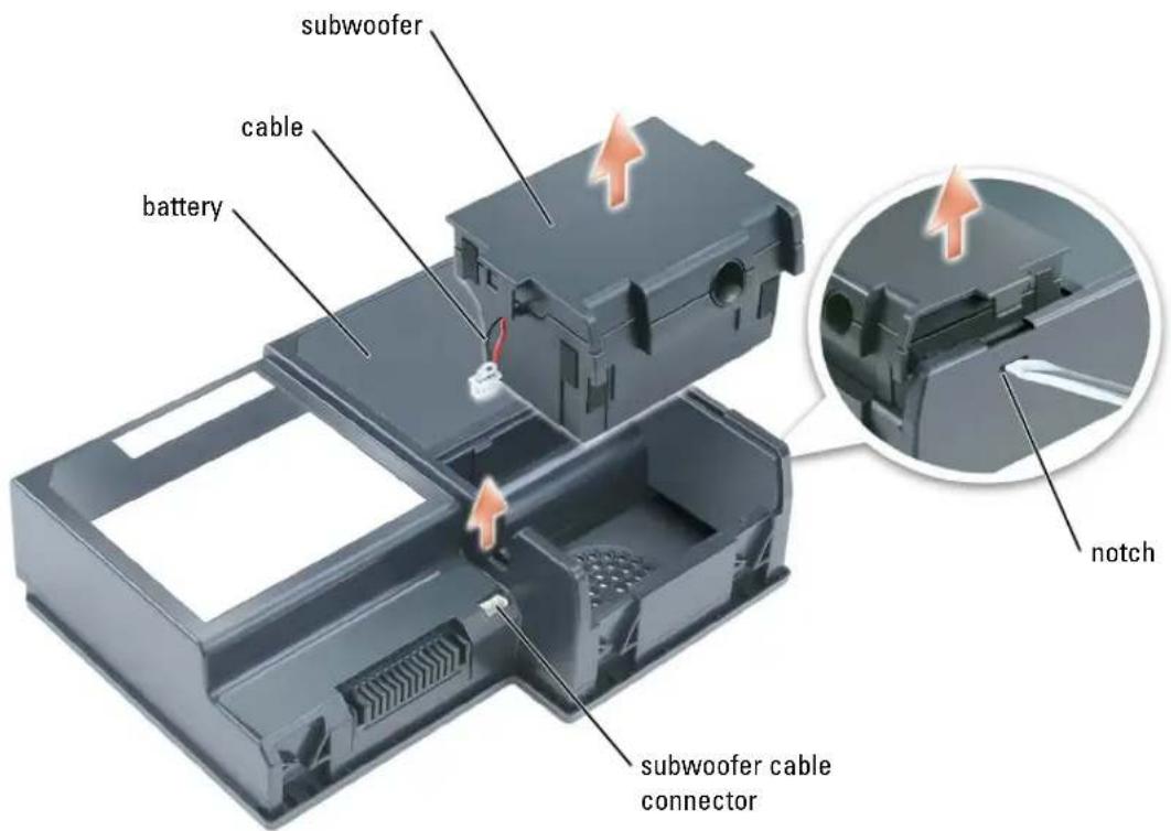
text_image
subwoofer cable battery notch subwoofer cable connector4 Insert the subwoofer into the compartment within the battery.
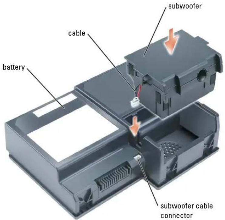
text_image
subwoofer cable battery subwoofer cable connector5 Connect the cable to the subwoofer connector.
6 Replace the battery in the battery bay (see page 53).
Keyboard
CAUTION: Before you begin this procedure, read the safety instructions at the front of this document (see page 11).
NOTICE: To avoid electrostatic discharge, ground yourself by using a wrist grounding strap or by periodically touching a connector on the back panel of the computer.
NOTICE: To avoid damaging the system board, you must remove the main battery before you begin working inside the computer.
1 Follow the procedures in "Before You Begin" (see page 103).
2 Remove the center hinge cover (see page 121).
NOTE: You do not need to remove the left and right hinge covers.
3 Remove the keyboard:
a Remove the two M2.5 x 3-mm screws across the top of the keyboard.

NOTICE: The keycaps on the keyboard are fragile, easily dislodged, and time-consuming to replace. Be careful when removing and handling the keyboard.
b Lift up the keyboard and gently slide it toward the display. c Hold the keyboard up and slightly forward to allow access to the keyboard connector.
d Pull up on the keyboard connector tab to disconnect the keyboard connector from the system board.
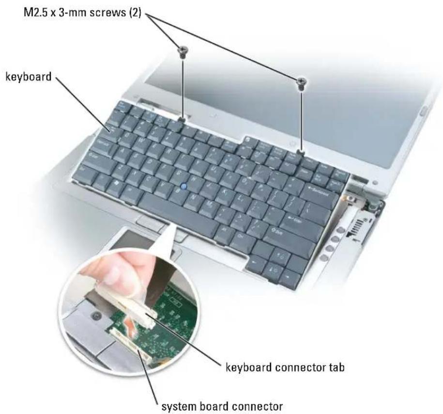
text_image
M2.5 x 3-mm screws (2) keyboard keyboard connector tab system board connector
NOTICE: To avoid scratching the palm rest when replacing the keyboard, hook the four tabs along the front edge of the keyboard into the palm rest, and then secure the keyboard in place.
PC Card With Bluetooth® Wireless Technology
CAUTION: Before you begin this procedure, read the safety instructions at the front of this document (see page 11).
NOTICE: To avoid electrostatic discharge, ground yourself by using a wrist grounding strap or by periodically touching a connector on the back panel of the computer.
NOTICE: To avoid damaging the system board, you must remove the main battery before you begin working inside the computer.
If you ordered a PC Card with Bluetooth wireless technology with your computer, it is already installed.
1 Remove the battery (see page 52).
2 Open the card door.
3 Using a plastic scribe or screwdriver, gently pry the module from the plastic guide bracket and the compartment so that you can disconnect the card from its cable and remove it from the computer.
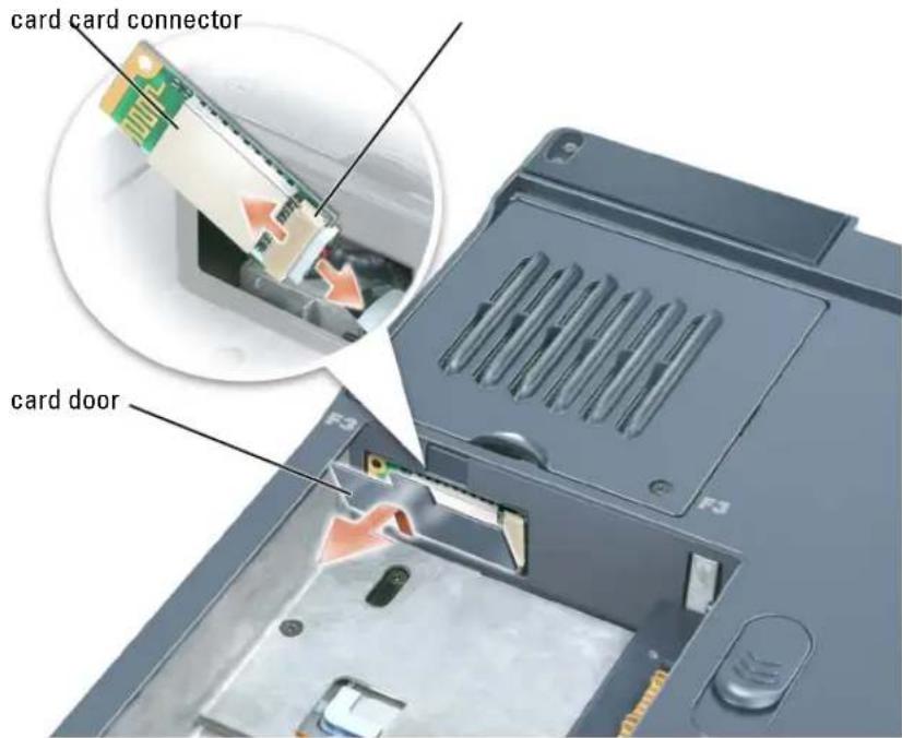
text_image
card card connector card doorModem

CAUTION: Before you begin this procedure, read the safety instructions at the front of this document (see page 11).

NOTICE: To avoid electrostatic discharge, ground yourself by using a wrist grounding strap or by periodically touching a connector on the back panel of the computer.
Removing the Modem
1 Follow the procedures in "Before You Begin" (see page 103).
2 Remove the center hinge cover (see page 121).
3 Remove the keyboard (see page 114).
4 Remove the M2 x 3-mm screw.
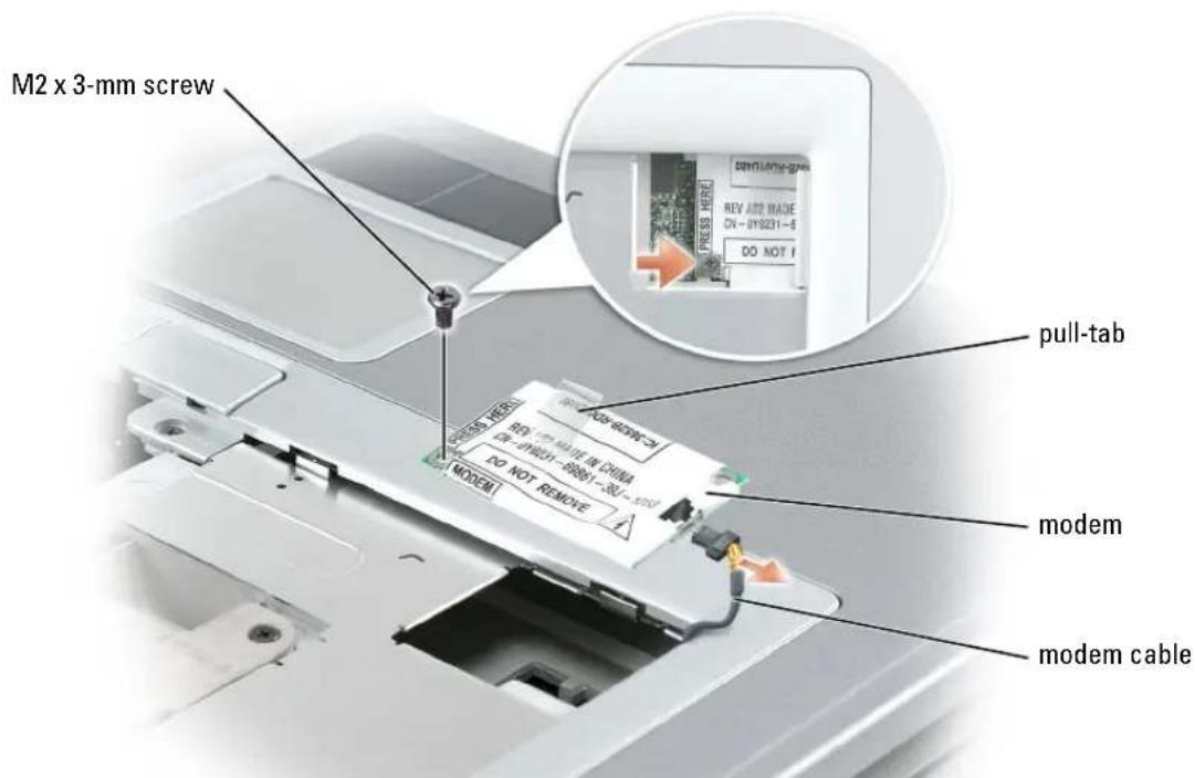
text_image
M2 x 3-mm screw pull-tab modem modem cable5 Pull up on the pull-tab to disconnect the modem from the modem connector on the system board.

NOTICE: Do not disconnect the modem cable from the system board.
6 Disconnect the modem cable from the modem.
Installing the Modem
1 Connect the modem cable to the modem.
NOTICE: Ensure that the modem cable is routed correctly when you replace the modem.
NOTICE: Do not press down on the left side of the modem while installing it.
2 Align the connector on the bottom of the modem with the modem connector on the system board, and then press down on the right side of the modem to seat both connectors.
3 Replace the M2 x 3-mm screw.
Keyboard Bracket
CAUTION: Before you begin this procedure, read the safety instructions at the front of this document (see page 11).
NOTICE: To avoid electrostatic discharge, ground yourself by using a wrist grounding strap or by periodically touching a connector on the back panel of the computer.
1 Follow the procedures in "Before You Begin" (see page 103).
2 Remove the center hinge cover (see page 121).
3 Remove the keyboard (see page 114).
4 Remove the display (see page 124).
5 Remove the palm rest (see page 130).
6 Remove the four M2.5 x 6-mm screws.
7 Pull up on the pull-tab on the FPC cable connector to disconnect the FPC cable from the keyboard bracket
8 Slightly lift up the keyboard bracket, move it approximately one inch toward the back of the computer, and then lift straight up to remove it.
©
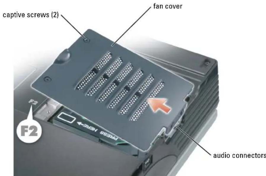
text_image
captive screws (2) fan cover F2 audio connectors4 Remove the screw on the fan and lift up the fan release lever.
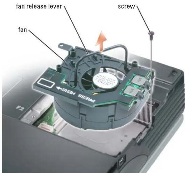
text_image
fan release lever fan screw F2 FRESS HERE5 Use the fan release lever to lift the fan out of the computer.
When replacing fan 2, press down on the fan surface labeled "Press here" to securely seat the fan in place.
To remove fan 3:
1 Unscrew the two captive screws labeled "F3."
2 Lift the fan out of the computer.

NOTE: The cover on this fan is not removable. It remains attached to the fan.
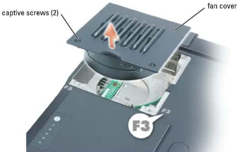
text_image
captive screws (2) fan cover F3 F3 F3Hinge Covers

CAUTION: Before you begin this procedure, read the safety instructions at the front of this document (see page 11).

NOTICE: To avoid electrostatic discharge, ground yourself by using a wrist grounding strap or by periodically touching a connector on the back panel of the computer.

NOTICE: To avoid damaging the system board, you must remove the main battery before you begin working inside the computer.
1 Follow the procedures in "Before You Begin" (see page 103).

NOTE: The hinge cover consists of three separate pieces: the left cover, the right cover, and the center cover. To remove computer components, you must remove all three covers except when removing the keyboard or the reserve battery. For these two components, remove only the center cover.
2 Remove the left and right hinge covers:
a Open the display.
NOTICE: To avoid damaging the cover, do not lift the center hinge cover on both sides simultaneously. b Slide the left and right hinge covers toward the back of the computer and then slide them to the side, away from the computer.
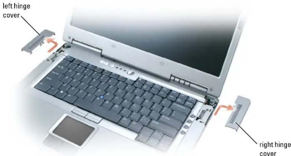
text_image
left hinge cover right hinge cover3 Remove the center hinge cover:
a Close the display.
b Facing the front of the computer, press in on the two hinge cover snaps and pull them up slightly to disengage them.
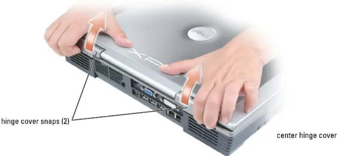
text_image
hinge cover snaps (2) center hinge coverc Open the display all the way (180 degrees) so that it lies flat against your work surface.
d Lift the center hinge cover on the right side first just enough to access the flex-cable connector.
e Using the pull-tab, disconnect the center-hinge-cover flex cable from the system board connector.
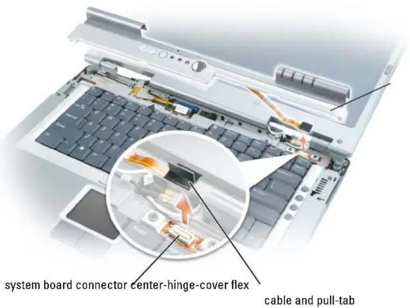
text_image
system board connector center-hinge-cover flex cable and pull-tabDisplay
CAUTION: Before you begin this procedure, read the safety instructions at the front of this document (see page 11).
NOTICE: To avoid electrostatic discharge, ground yourself by using a wrist grounding strap or by periodically touching a connector on the back panel of the computer.
NOTICE: To avoid damaging the system board, you must remove the main battery before you begin working inside the computer.
1 Follow the procedures in "Before You Begin" (see page 103).
NOTICE: Before turning the computer over and removing the screws, ensure that the display is firmly latched closed.
2 Turn the computer over and remove the four screws (two on each side) labeled "D" on the bottom of the computer.
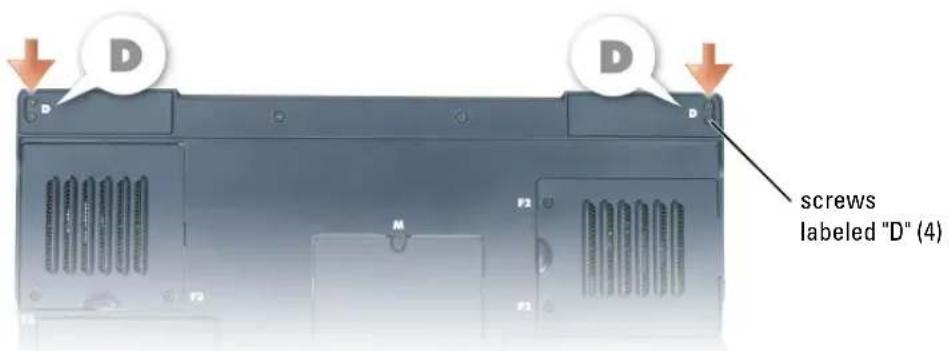
text_image
D D screws labeled "D" (4)3 Turn the computer right-side up.
4 Remove the left, right, and center hinge covers (see page 121).
5 Disconnect the antenna cables (pull to separate the connectors).
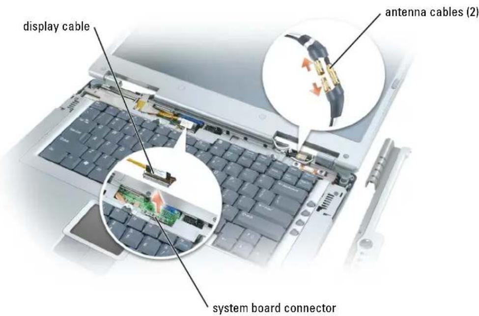
text_image
display cable antenna cables (2) system board connector6 Disconnect the display cable, using the pull-tab.
7 Lift the display out of the computer at a 90-degree angle.
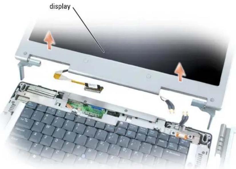
text_image
displayWhen you replace the display, ensure that the ribbon tape around the display cable is securely tucked underneath the two tabs.
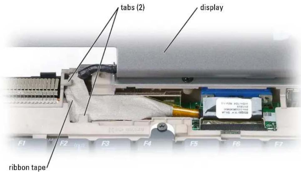
text_image
tabs (2) display ribbon tapeAlso, ensure that the antenna cables are not twisted and that they are lying flat in the antenna cable clip.
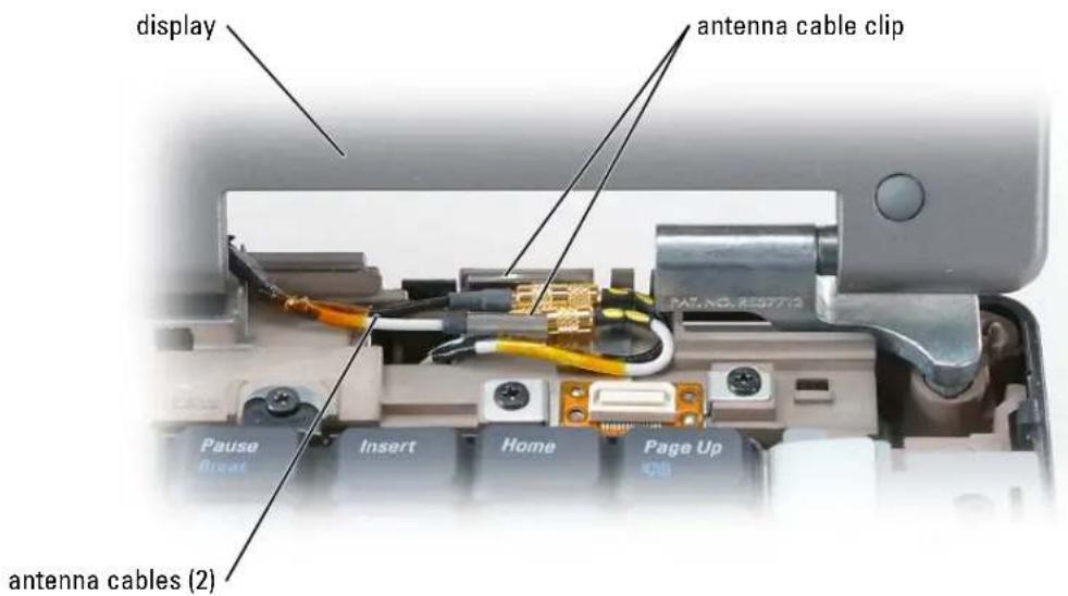
text_image
display antenna cable clip PAS.NO.159772 Pause Break Insert Home Page Up (2) antenna cables (2)Display Latch

CAUTION: Before you begin this procedure, read the safety instructions at the front of this document (see page 11).

NOTICE: To avoid electrostatic discharge, ground yourself by using a wrist grounding strap or by periodically touching a connector on the back panel of the computer.

NOTICE: To avoid damaging the system board, you must remove the main battery before you begin working inside the computer.
1 Follow the procedures in "Before You Begin" (see page 103).
2 Remove the display (see page 124).
3 Remove the eight rubber display bumpers.
4 Remove the two M2.5 x 6-mm shoulder screws and six M2.5 x 6-mm screws, and remove the display bezel.
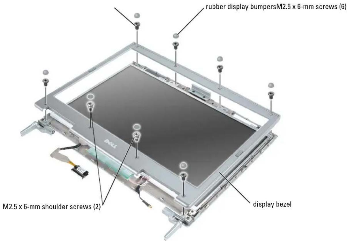
text_image
rubber display bumpersM2.5 x 6-mm screws (6) M2.5 x 6-mm shoulder screws (2) display bezel5 Remove the two M2 x 4-mm screws and remove the display latch.
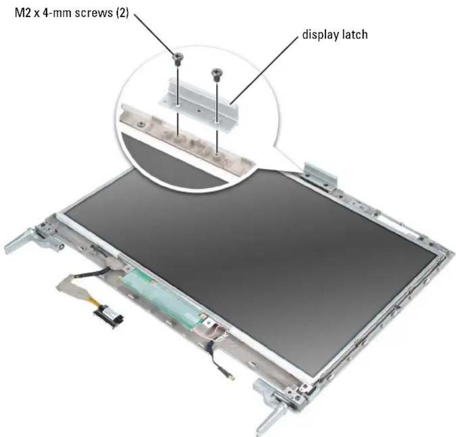
text_image
M2 x 4-mm screws (2) display latchVideo Card

CAUTION: Before you begin this procedure, read the safety instructions at the front of this document (see page 11).

NOTICE: To avoid electrostatic discharge, ground yourself by using a wrist grounding strap or by periodically touching a connector on the back panel of the computer.
1 Follow the procedures in "Before You Begin" (see page 103).
2 Remove the center hinge cover (see page 121).
3 Remove the keyboard (see page 114).
4 Remove the display (see page 124).
5 Remove the keyboard bracket (see page 118).
6 Remove the four M2.5 x 6-mm screws from the video card.
7 Lift up the video card to remove it.
The video-card heat sink is part of the video card assembly.
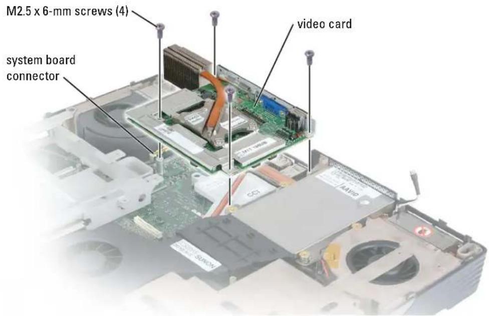
text_image
M2.5 x 6-mm screws (4) video card system board connectorProcessor Thermal-Cooling Assembly

CAUTION: Before you begin this procedure, read the safety instructions at the front of this document (see page 11).

NOTICE: To avoid electrostatic discharge, ground yourself by using a wrist grounding strap or by periodically touching a connector on the back panel of the computer.
Removing the Processor Thermal-Cooling Assembly
1 Follow the procedures in "Before You Begin" (see page 103).
2 Remove the center hinge cover (see page 121).
3 Remove the keyboard (see page 114).
4 Remove the display (see page 124).
5 Remove the keyboard bracket (see page 118).
6 Remove the video card (see page 128).
7 Loosen in consecutive order the four captive screws, labeled "1" through "4," that secure the processor thermal-cooling assembly to the system board.
8 Lift up the processor thermal-cooling assembly and remove it from the system board.
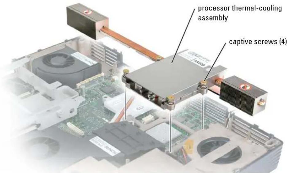
text_image
processor thermal-cooling assembly captive screws (4)Installing the Processor Thermal-Cooling Assembly
1 Place the processor thermal-cooling assembly over the processor.
2 Tighten the four captive screws, labeled "1" through "4," in consecutive order.
Palm Rest

CAUTION: Before you begin this procedure, read the safety instructions at the front of this document (see page 11).

NOTICE: To avoid electrostatic discharge, ground yourself by using a wrist grounding strap or by periodically touching a connector on the back panel of the computer.
1 Follow the procedures in "Before You Begin" (see page 103).
2 Remove the center hinge cover (see page 121).
3 Remove the keyboard (see page 114).
4 Remove the display (see page 124).
5 Remove the keyboard bracket (see page 118).
6 Turn over the computer and remove the three M2.5 x 8-mm screws labeled "circle P."
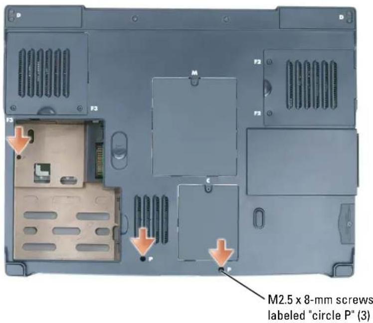
text_image
M2.5 x 8-mm screws labeled "circle P" (3)7 Turn the computer top-side up and remove the four M2.5 x 3-mm screws labeled "circle P."
8 Disconnect the touch-pad connector from the system board.
9 Slide the palm rest forward and remove it from the computer.
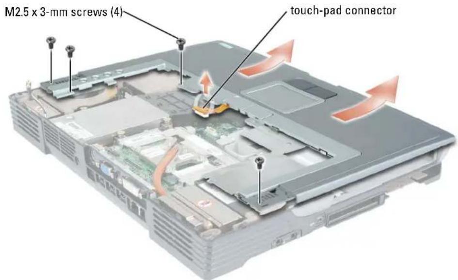
text_image
M2.5 x 3-mm screws (4) touch-pad connectorProcessor Module
Removing the Processor Module
CAUTION: Before you begin this procedure, read the safety instructions at the front of this document (see page 11).
NOTICE: To avoid electrostatic discharge, ground yourself by using a wrist grounding strap or by periodically touching a connector on the back panel of the computer.
NOTICE: Do not touch the processor die. Press and hold the processor down on the substrate on which the die is mounted while turning the cam screw to prevent intermittent contact between the cam screw and processor.
NOTICE: To avoid damage to the processor, hold the screwdriver so that it is perpendicular to the processor when turning the cam screw.
1 Follow the instructions in "Before You Begin" on page 103.
2 Remove the video card (see page 128).
3 Remove the keyboard (see page 114).
4 Remove the fan (see page 119).
NOTICE: To help ensure maximum cooling for the processor, do not touch the heat transfer areas on the processor thermal-cooling assembly. The oils in your skin reduce the heat transfer capability of the thermal pads.
5 Remove the processor thermal-cooling assembly.
NOTICE: When removing the processor module, pull the module straight up. Be careful not to bend the pins on the processor module.
6 To loosen the ZIF socket, use a small, flat-blade screwdriver and rotate the ZIF-socket cam screw counterclockwise until it comes to the cam stop.
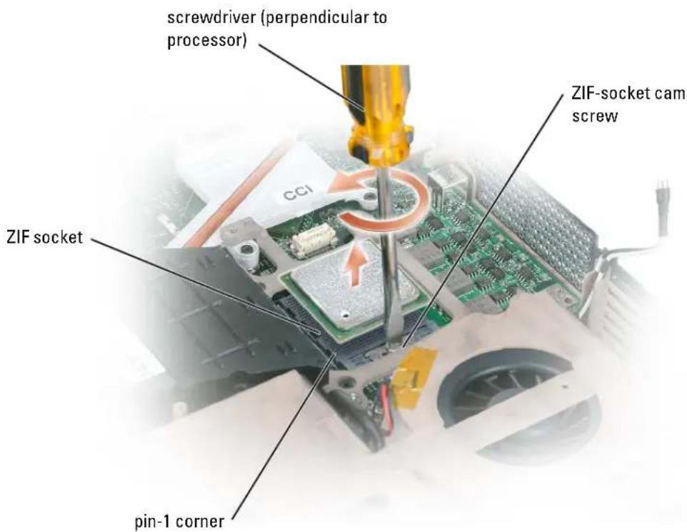
text_image
screwdriver (perpendicular to processor) ZIF socket CCI ZIF-socket cam screw pin-1 cornerNOTE: The ZIF-socket cam screw secures the processor to the system board. Take note of the arrow on the ZIF-socket cam screw, which indicates the direction to turn the cam screw.
7 Lift out the processor module.
Installing the Processor Module
NOTICE: Ensure that the cam lock is in the fully open position before seating the processor module. Seating the processor module properly in the ZIF socket does not require force.
NOTICE: A processor module that is not properly seated can result in an intermittent connection or permanent damage to the processor and ZIF socket.
1 Align the pin-1 corner of the processor module with the pin-1 corner of the ZIF socket, and insert the processor module.
NOTE: The pin-1 corner of the processor module has a triangle that aligns with the triangle on the pin-1 corner of the ZIF socket.
NOTICE: You must position the processor module correctly in the ZIF socket to avoid permanent damage to the module and the socket.
When the processor module is correctly seated, all four corners are aligned at the same height. If one or more corners of the module are higher than the others, the module is not seated correctly.
2 Tighten the ZIF socket by turning the cam screw clockwise to secure the processor module to the system board.
3 Perform the steps in "Removing the Processor Module" on page 132 in reverse order, beginning with step 5.
4 Update the BIOS using the flash BIOS update program floppy disk or CD. For instructions on how to flash the BIOS, see the following section.
Flashing the BIOS
1 Ensure that the AC adapter is plugged in and that the main battery is installed properly.
2 Insert the flash BIOS update program floppy disk or CD and turn on the computer.
Follow the instructions that appear on the screen. The computer continues to boot and updates the new BIOS. When the update is complete, the computer will automatically reboot.
3 Press <1^2> during POST to enter the system setup program.
4 Press
5 Press
6 Remove the flash BIOS update program floppy disk or CD from the drive and restart the computer.
Reserve Battery
CAUTION: Before you begin this procedure, read the safety instructions at the front of this document (see page 11).
NOTICE: To avoid electrostatic discharge, ground yourself by using a wrist grounding strap or by periodically touching a connector on the back panel of the computer.

NOTICE: To avoid damaging the system board, you must remove the main battery before you begin working inside the computer.
1 Follow the procedures in "Before You Begin" (see page 103).
2 Remove the center hinge cover (see page 121).

NOTE: You do not need to remove the left and right hinge covers.
3 Remove the keyboard (see page 114).
4 Disconnect the reserve battery cable connector from the system board.
5 Lift the reserve battery clip slightly to disengage it from the fan chassis.
6 Pull the reserve battery together with the clip straight out of the computer base.
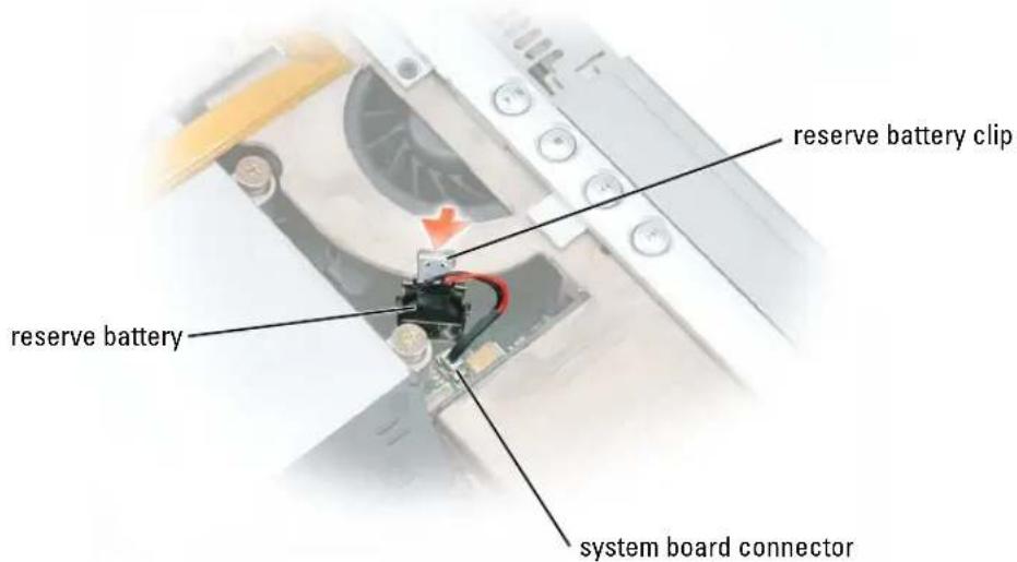
text_image
reserve battery clip reserve battery system board connector
NOTE: Use a scribe to press the reserve battery cable connector into the system board connector when replacing the reserve battery.
System Board
Removing the System Board

CAUTION: Before you begin this procedure, read the safety instructions at the front of this document (see page 11).

NOTICE: To avoid electrostatic discharge, ground yourself by using a wrist grounding strap or by periodically touching a connector on the back panel of the computer.
The system board's BIOS chip contains the Service Tag, which is also visible on a barcode label on the bottom of the computer. The replacement kit for the system board includes a CD that provides a utility for transferring the Service Tag to the replacement system board.

NOTICE: Disconnect the computer and any attached devices from electrical outlets, and remove any installed batteries.
1 Remove the keyboard (see page 114).
2 Remove the display (see page 124).
3 Remove the palm rest (see page 130).
4 Remove the video card (see page 128).
5 Remove the processor thermal-cooling assembly (see page 129).
6 Remove the processor (see page 132).
7 Turn the system over and remove the two M2.5 x 6-mm screws from the system-board bottom assembly.
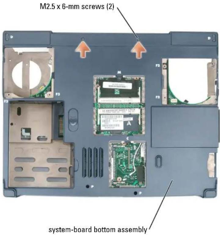
text_image
M2.5 x 6-mm screws (2) system-board bottom assembly8 Turn the system top-side up again, and remove the four M2.5 x 6-mm screws from the system-board top assembly.
9 With the front of the computer facing you, lift the system-board top assembly from the right side, swinging it up, then lift the left side and draw the system-board top assembly out of the computer.
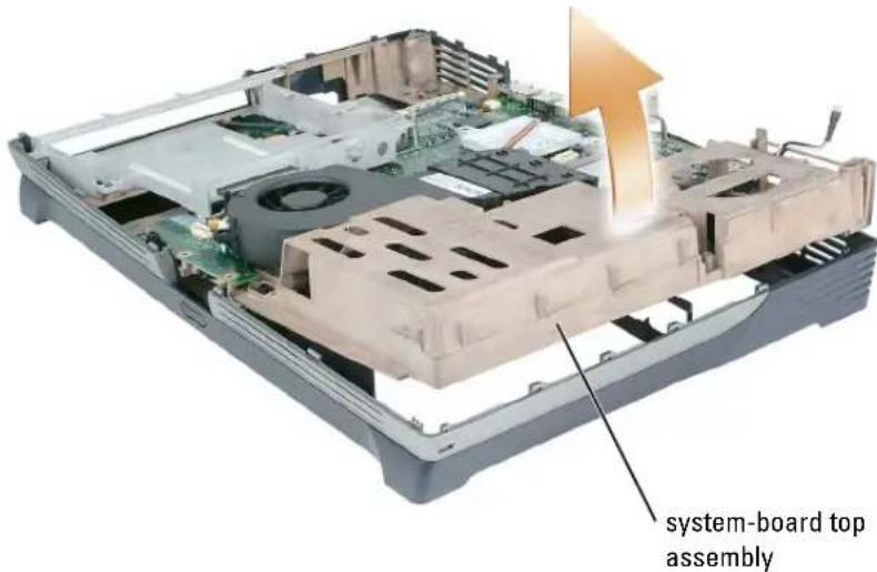
text_image
system-board top assemblyInstalling the System Board
1 Perform all of the steps in "Removing the System Board" on page 135 in reverse order.

NOTICE: Before turning on the computer, replace all screws and ensure that no stray screws remain inside the computer. Failure to do so may result in damage to the computer.
2 Turn on the computer.

NOTE: After replacing the system board, you must enter the computer Service Tag sequence into the BIOS of the replacement system board as part of the BIOS update procedure.
3 Insert the flash BIOS update program floppy disk or CD that accompanied the replacement system board into the appropriate drive. Follow the instructions that appear on the screen.
Speakers
CAUTION: Before you begin this procedure, read the safety instructions at the front of this document (see page 11).
NOTICE: To avoid electrostatic discharge, ground yourself by using a wrist grounding strap or by periodically touching a connector on the back panel of the computer.
1 Follow the procedures in "Before You Begin" (see page 103).
2 Remove the center hinge cover (see page 121).
3 Remove the keyboard (see page 114).
4 Remove the display (see page 124).
5 Remove the palm rest (see page 130).
6 Remove the keyboard bracket (see page 118).
NOTICE: Handle the speakers with care to avoid damaging them.
7 Remove the three M2.5 x 5-mm screws from the speakers.
8 Lift up the speakers.
9 Disconnect the speaker connector from the system board connector.
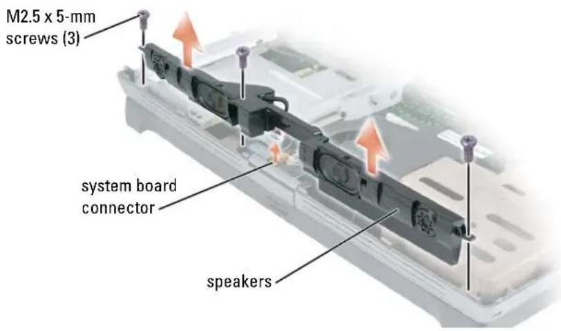
text_image
M2.5 x 5-mm screws (3) system board connector speakersDisplay Latch Release

CAUTION: Before you begin this procedure, read the safety instructions at the front of this document (see page 11).

NOTICE: To avoid electrostatic discharge, ground yourself by using a wrist grounding strap or by periodically touching a connector on the back panel of the computer.
1 Remove the hard drive (see page 105).
2 Remove the keyboard (see page 114).
3 Remove the display (see page 124).
4 Remove the palm rest (see page 130).
5 Remove the system board (see page 135).
6 Remove the speakers (see page 138).
7 Remove the two M2.5x 6-mm screws on each side of the latch.
8 Pull the latch straight up and away from the computer base.
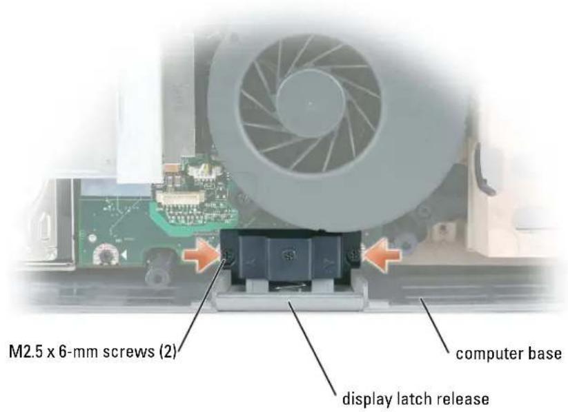
text_image
M2.5 x 6-mm screws (2) computer base display latch releasePin Assignments for I/O Connectors
USB Connector
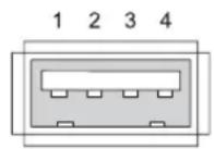
Pin Signal
| 1 USB5V+ |
| 2 USBP- |
| 3 USBP+ |
| 4 GND |
Video Connector
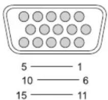
text_image
5 —— 1 10 —— 6 15 —— 11Pin Signal Pin Signal
| 1 CRT_R 9 5V+ |
| 2 CRT_G 10 GND |
| 3 CRT_B 11 MONITOR_DETECT- |
| 4 NC 12 DDC_DATA |
| 5 GND 13 CRT_HS |
| 6 GND 14 CRT_VS |
| 7 GND 15 DDC_CLK |
| 8 GND |
S-Video TV-Out Connector
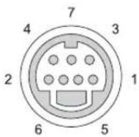
text_image
7 4 3 2 1 6 5S-Video
Pin Signal
1 GND
2 GND
3 DILUMA-L
4 DCRMA-L
Composite Video
Pin Signal
5 NC
6 DCMPS-L
7 GND
IEEE 1394 Connector
1234
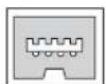
Pin Signal
1 TPB-
2 TPB+
3 TPA-
4 TPA+
DVI-I Connector
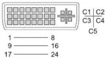
Pin Signal Pin Signal
| 1 | TMDS DATA2- | 13 | TMDS DATA3+ |
| 2 | TMDS DATA2+ 14+5V | ||
| 3 | TMDS DATA2/4 SHLD | 15 | GND (FOR +5V) |
| 4 | TMDS DATA4- | 16 | IIOT PLUG DETECT |
| 5 | TMDS DATA4+ | 17 | TMDS DATA0- |
| 6 | DDC CLK 18 | TMDS DATA0+ | |
| 7 | DDC DATA | 19 | TMDS DATA0/5 SHLD |
| 8 | ANALOG VERT SYNC 20 | TMDS DATA5- | |
| 9 | TMDS DATA1- 21 | TMDS DATA5+ | |
| 10 | TMDS DATA1+ | 22 | TMDS CLK SHLD |
| 11 | TMDS DATA1/3 SHLD | 23 | TMDS CLK+ |
| 12 | TMDS DATA3- | 24 | TMDS CLK- |
Pin Signal
| C1 | ANALOG RED VID OUT |
| C2 | ANALOG GRN VID OUT |
| C3 | ANALOG BLU VID OUT |
| C4 | ANALOG IOR SYNC |
| C5 | ANALOG COM GND RET |
Appendix
Specifications
Processor
| Processor type Intel | ^ Pentium ^ 4 withHyper-Threading technologyIntel Pentium 4, Extreme Edition, withHyper-Threading technology |
| External bus frequency 800 MHz | |
System Information
| System chip set Intel 865PE |
| Data bus width 64 bits |
| DRAM bus width dual-channel DDR memory, 64 bits per channel |
| Processor address bus width 32 bits |
| Flash EPROM 1 MB |
| Graphics bus 64 bits |
| PCI bus 32 bits |
PC Card
| CardBus controller Texas Instruments PCI 4510 | |
| PC Card connector one (supports one Type I or Type II card) | |
| Cards supported | 3.3 V and 5 V |
| PC Card connector size | 68 pins |
| Data width (maximum) | PCMCIA 16 bitsCardBus 32 bits |
Memory
Memory module connector dual-channel DDR, two user-accessible DDR SODIMM connectors, single SODIMM per channel
Memory module capacities 128 MB, 256 MB, 512 MB, and 1024 MB
Memory type PC3200
Memory configuration support dual-channel only
NOTE: To get dual-channel memory bandwidth capability, both the connectors must contain memory modules and they must be of the same size and configuration.
Minimum memory 256 MB
Maximum memory 2048 MB
Ports and Connectors
Video 15-hole connector
Digital-video interface (DVI-I) one 24-hole connector
Audio microphone miniconnector, stereo
headphone/speakers miniconnector; S/PDIF connector
USB three 4-pin USB 2.0-compliant connectors
D/Bay (powered USB) connector 4-pin power supply
IEEE 1394 4-pin mini, nonpowered connector
Infrared sensor compatible with IrDA Standard 1.1 (Fast IR)
S-video TV-out 7-pin mini-DIN connector (optional S-video to composite video adapter cable)
Mini PCI Type IIIA Mini PCI card slot
Modem RJ-11 port
Network adapter RJ-45 port
Communications
Modem:
Type v.92 56K MDC
Controller softmodem
Interface internal AC'97 bus
Communications (continued)
Network adapter 10/100/1000 Ethernet LAN on system board
Wireless internal Mini PCI Wi-Fi wireless support;
PC Card with Bluetooth ^® wireless technology
Video
Video type 64-bit hardware accelerated
Data bus 8X AGP
Video controller ATI Mobility RADEON 9700
Video memory 64 MB and 128 MB
LCD interface LVDS
TV support NTSC or PAL in S-video and composite modes
Audio
Audio type compatible with Soundblaster and
Microsoft ^® Windows ^® Sound System
Audio controller Intel AC'97
Stereo conversion 20-bit (stereo digital-to-analog)
18-bit (stereo analog-to-digital)
Interfaces:
Internal AC'97
External microphone miniconnector, stereo headphones/speakers miniconnector S/PDIF connector
Speaker two 4-ohm speakers
Internal speaker amplifier 2-W per channel stereo into 4 ohms, two speakers per channel 5-W mono into 8 ohms (for the subwoofer) Volume controls key combinations; program menus
Display
| Type (active-matrix TFT) WUXGA; WSXGA+; WXGA | |
| Dimensions: | |
| Height | 222.5 mm (8.8 inches) |
| Width | 344.5 mm (13.6 inches) |
| Diagonal | 391.2 mm (15.4 inches) |
| Maximum resolutions | 1920 x 1200 (WUXGA);1680 x 1050 (WSXGA+);1280 x 800 (WXGA) |
| Response time (typical) 20-ms rise (maximum),35-ms fall (maximum) | |
| Refresh rate 60 Hz | |
| Operating angle 0° (closed) to 180° | |
| Viewing angles: | |
| Horizontal | ±55° |
| Vertical | ±48° |
| Pixel pitch 0.1725 mm (WUXGA) | 0.1971 mm (WSXGA+)0.2588 mm (WXGA) |
| Power Consumption: | |
| Panel with backlight (typical) | 7.0 W (WUXCA)6.0 W (WSXCA+)5.5 W (WXGA) |
| Controls brightness can be controlled through key combinations | |
Keyboard
| Number of keys 87 (U.S. and Canada); 88 (Europe); 91 (Japan) |
| Layout QWERTY/AZERTY/Kanji |
Touch Pad
| X/Y position resolution(graphics table mode) 240 cpi | |
| Size: | |
| Width | 64.9-mm (2.5-inch) sensor-active area |
| Height | 48.9-mm (1.9-inch) rectangle |
Track Stick
| X/Y position resolution(graphics table mode) 250 count/sec @ 100 gf |
| Size protrudes 0.5 mm higher than surrounding keycaps |
Battery
| Type 12-cell, 95-WHr "smart" lithium ion | |
| dual 8-cell, 66-WHr "smart" lithium ion | |
| Dimensions: | |
| Depth | 88.5 mm (3.5 inches) |
| Height | 21.5 mm (0.8 inch) |
| Width | 139.0 mm (5.5 inches) |
| Weight 12 cell: 0.6 kg (1.4 lb); dual 8 cell: 0.95 kg(2.1 lb) | |
Voltage 14.8 VDC
Charge time (approximate):
| Computer on | 2.5 hours |
| Computer off | 1.5 hours |
Operating time Battery operating time varies depending on operating conditions and can be significantly reduced under certain power-intensive conditions. See "Using a Battery" on page 49 for more information on battery life.
Life span (approximate) 500 discharge/charge cycles
Battery (continued)
| Temperature range: | |
| Operating | 0^ to 35^ ( 32^ to 95^ ) |
| Storage | -40^ to 65^ ( -40^ to 149^ ) |
AC Adapter
| Input voltage 90–264 VAC |
| Input current (maximum) 2.5 A |
| Input frequency 47–63 Hz |
| Output current 9 A (maximum at 4-second pulse);7.3–8.1 A (continuous) |
Output power 150 W
NOTICE: Do not use an AC adapter rated at less than 150 W with this computer.
Rated output voltage 19.5 VDC
Dimensions:
| Height | 40.0 mm (1.6 inches) |
| Width | 85.0 mm (3.4 inches) |
| Depth | 170.0 mm(6.7 inches) |
Weight (with cables) 0.68–1.09 kg (1.5–2.4 lb)
Temperature range:
| Operating | 0° to 40°C (32° to 104°F) |
| Storage | -40° to 70°C (-40° to 158°F) |
Physical
| Height 50.6 mm (1.9 inches) | |
| Width 358.9 mm (14.1 inches) | |
| Depth 373.7 mm (10.8 inches) | |
| Weight: | |
| With combo drive | 4.0 kg (8.9 lb) |
| With DVD drive | 3.9 kg (8.8 lb) |
Environmental
| Temperature range: | |
| Operating | 0° to 35°C (32° to 95°F) |
| Storage | -40° to 65°C (-40° to 149°F) |
| Relative humidity (maximum): | |
| Operating | 10% to 90% (noncondensing) |
| Storage | 5% to 95% (noncondensing) |
| Maximum vibration (using a random-vibration spectrum that simulates user environment): | |
| Operating | 0.7 CRMS |
| Storage | 1.3 CRMS |
| Maximum shock (measured with hard drive in head-parked position and a 2-ms half-sinc pulse): | |
| Operating | 122 G |
| Storage | 163 G |
| Altitude (maximum): | |
| Operating | -15.2 to 3048 m (-50 to 10,000 ft) |
| Storage | -15.2 to 10,668 m (-50 to 35,000 ft) |
Using the System Setup Program
Overview

NOTE: Your operating system may automatically configure most of the options available in system setup, thus overriding options that you set through system setup. For more information on configuring features for your operating system, see the Help and Support Center. To access the Help and Support Center, see page 19.
The system setup screens display the current setup information and settings for your computer, such as:
- System configuration
- Boot order
- Boot (start-up) configuration
- Basic device-configuration settings
- System security and hard-drive password settings

NOTICE: Unless you are an expert computer user or are directed to do so by Dell technical support, do not change the system setup settings. Certain changes might make your computer work incorrectly.
Viewing the System Setup Screens
1 Turn on (or restart) your computer.
2 When the DELL ^™ logo appears, press
System Setup Screens

NOTE: For information about a specific item on a system setup screen, highlight the item and see the Help area on the screen.
On each screen, the system setup options are listed at the left. To the right of each option is the setting or value for that option. You can change settings that appear as white type on the screen. Options or values that you cannot change (because they are determined by the computer) appear less bright.
The upper-right corner of the screen displays help information for the currently highlighted option; the lower-right corner displays information about the computer. System-setup key functions are listed across the bottom of the screen.
Commonly Used Options
Certain options require that you reboot the computer for new settings to take effect.
Changing the Boot Sequence
The boot sequence, or boot order, tells the computer where to look to find the software needed to start the operating system. You can control the boot sequence and enable/disable devices using the Boot Order page of system setup.

NOTE: To change the boot sequence on a one-time-only basis, see "Performing a One-Time Boot" on page 151.
The Boot Order page displays a general list of the bootable devices that may be installed in your computer, including but not limited to the following:
- Diskette Drive
- Modular bay HDD
- Internal HDD
• CD/DVD/CD-RW drive
During the boot routine, the computer starts at the top of the list and scans each enabled device for the operating system start-up files. When the computer finds the files, it stops searching and starts the operating system.
To control the boot devices, select (highlight) a device by pressing the down-arrow or up-arrow key, and then enable or disable the device or change its order in the list.
- To enable or disable a device, highlight the item and press the space bar. Enabled items appear as white and display a small triangle to the left; disabled items appear blue or dimmed without a triangle.
- To reorder a device in the list, highlight the device and then press or
(not case-sensitive) to move the highlighted device up or down.
Boot sequence changes take effect as soon as you save the changes and exit system setup.
Performing a One-Time Boot
You can set a one-time-only boot sequence without entering system setup. (You can also use this procedure to boot the Dell Diagnostics on the diagnostics utility partition on your hard drive.)
1 Shut down the computer through the Start menu.
2 Connect the computer to an electrical outlet.
3 Turn on the computer. When the DELL logo appears, press
4 When the boot device list appears, highlight the device from which you want to boot and press
The computer boots to the selected device.
The next time you reboot the computer, the previous boot order is restored.
Enabling the Infrared Sensor
1 Enter the system setup program:
a Turn on your computer.
b Press
2 Press until you locate Infrared Data Port under Basic Device Configuration. 3 Press the down-arrow key to select the Infrared Data Port setting, and press the right-arrow key to change the setting to a COM port. After you enable the infrared sensor, you can use it to establish a link to an infrared device. To set up and use an infrared device, see the infrared device documentation and the Microsoft ^® Windows ^® XP Help and Support Center. To access the Help and Support Center, see page 19. Technician-assisted technical support requires the cooperation and participation of the customer in the troubleshooting process and provides for restoration of the operating system, software programs, and hardware drivers to the original default configuration as shipped from Dell, as well as the verification of appropriate functionality of the computer and all Dell-installed hardware. In addition to this technician-assisted technical support, online technical support is available at support.dell.com. Additional technical support options may be available for purchase. Dell provides limited technical support for the computer and any "Dell-installed" software and peripherals ^1 . Support for third-party software and peripherals is provided by the original manufacturer, including those purchased and/or installed through Dell Software and Peripherals, Readyware, and Custom Factory Integration ^2 . ^1 Repair services are provided pursuant to the terms and conditions of your limited warranty and any optional support service contract purchased with the computer. Dell-installed software includes the operating system and some of the software programs that are installed on the computer during the manufacturing process (Microsoft® Office, Norton Antivirus, and so on). Dell-installed peripherals include any internal expansion cards, or Dell-branded module bay or PC Card accessories. In addition, any Dell-branded monitors, keyboards, mice, speakers, microphones for telephonic modems, port replicators, networking products, and all associated cabling are included. Third-party software and peripherals include any peripheral, accessory, or software program sold by Dell not under the Dell brand (printers, scanners, cameras, games, and so on). Support for all third-party software and peripherals is provided by the original manufacturer of the product. To contact Dell electronically, you can access the following websites: For specific web addresses for your country, find the appropriate country section in the table below. NOTE: Toll-free numbers are for use within the country for which they are listed. When you need to contact Dell, use the electronic addresses, telephone numbers, and codes provided in the following table. If you need assistance in determining which codes to use, contact a local or an international operator. Electromagnetic Interference (EMI) is any signal or emission, radiated in free space or conducted along power or signal leads, that endangers the functioning of a radio navigation or other safety service or seriously degrades, obstructs, or repeatedly interrupts a licensed radio communications service. Radio communications services include but are not limited to AM/FM commercial broadcast, television, cellular services, radar, air-traffic control, pager, and Personal Communication Services (PCS). These licensed services, along with unintentional radiators such as digital devices, including computers, contribute to the electromagnetic environment. Electromagnetic Compatibility (EMC) is the ability of items of electronic equipment to function properly together in the electronic environment. While this computer has been designed and determined to be compliant with regulatory agency limits for EMI, there is no guarantee that interference will not occur in a particular installation. If this equipment does cause interference with radio communications services, which can be determined by turning the equipment off and on, you are encouraged to try to correct the interference by one or more of the following measures: If necessary, consult a Dell Technical Support representative or an experienced radio/television technician for additional suggestions. For additional regulatory information, see the Dell Inspiron Help file that accompanied your computer. To access the help file, see page 18. The following information is provided on the device(s) described in this document in compliance with the requirements of the official Mexican standards (NOM): Exporter: Dell Inc. One Dell Way Round Rock, TX 78682 Importer: Dell Computer de México, S.A. de C.V. Paseo de la Reforma 2620 - 11° Piso Col. Lomas Altas 11950 México, D.F. Ship to: Dell Computer de México, S.A. de C.V. al Cuidado de Kuehne & Nagel de México S. de R.L. Avenida Soles No. 55 Col. Peñon de los Baños 15520 México, D.F. Model number: PP09L Supply voltage: 100–240 VAC Frequency: 50–60 Hz Current consumption: 2.5 A Output voltage: 19.5 V Output current: 7.7 A Dell-branded hardware products purchased in the U.S. or Canada come with either a 90-day, 1-year, 2-year, 3-year, or 4-year limited warranty. To determine which warranty came with your hardware product(s), see your packing slip or invoice. The following sections describe the limited warranties for the U.S., the limited warranties for Canada, the manufacturer guarantee for Latin America and the Caribbean, and the Intel® Pentium® and Celeron® warranty for the U.S. and Canada. This limited warranty covers defects in materials and workmanship in your—our end-user customer's—Dell-branded hardware products, including Dell-branded peripheral products. This limited warranty does not cover: - Problems that result from: - Products with missing or altered Service Tags or serial numbers - Products for which Dell has not received payment THIS WARRANTY GIVES YOU SPECIFIC LEGAL RIGHTS, AND YOU MAY ALSO HAVE OTHER RIGHTS WHICH VARY FROM STATE TO STATE (OR JURISDICTION TO JURISDICTION). DELL'S RESPONSIBILITY FOR MALFUNCTIONS AND DEFECTS IN HARDWARE IS LIMITED TO REPAIR AND REPLACEMENT AS SET FORTH IN THIS WARRANTY STATEMENT. ALL EXPRESS AND IMPLIED WARRANTIES FOR THE PRODUCT, INCLUDING BUT NOT LIMITED TO ANY IMPLIED WARRANTIES AND CONDITIONS OF MERCHANTABILITY AND FITNESS FOR A PARTICULAR PURPOSE, ARE LIMITED IN TIME TO THE TERM OF THE LIMITED WARRANTY PERIOD REFLECTED ON YOUR PACKING SLIP OR INVOICE. NO WARRANTIES, WHETHER EXPRESS OR IMPLIED, WILL APPLY AFTER THE LIMITED WARRANTY PERIOD I HAS EXPIRED. SOME STATES DO NOT ALLOW LIMITATIONS ON HOW LONG AN IMPLIED WARRANTY LASTS, SO THIS LIMITATION MAY NOT APPLY TO YOU. WE DO NOT ACCEPT LIABILITY BEYOND THE REMEDIES PROVIDED FOR IN THIS LIMITED WARRANTY OR FOR CONSEQUENTIAL OR INCIDENTAL DAMAGES, INCLUDING, WITHOUT LIMITATION, ANY LIABILITY FOR THIRD-PARTY CLAIMS AGAINST YOU FOR DAMAGES, FOR PRODUCTS NOT BEING AVAILABLE FOR USE, OR FOR LOST DATA OR LOST SOFTWARE. OUR LIABILITY WILL BE NO MORE THAN THE AMOUNT YOU PAID FOR THE PRODUCT THAT IS THE SUBJECT OF A CLAIM. THIS IS THE MAXIMUM AMOUNT FOR WHICH WE ARE RESPONSIBLE. SOME STATES DO NOT ALLOW THE EXCLUSION OR LIMITATION OF INCIDENTAL OR CONSEQUENTIAL DAMAGES, SO THE ABOVE LIMITATION OR EXCLUSION MAY NOT APPLY TO YOU. This limited warranty lasts for the time period indicated on your packing slip or invoice, except for the following Dell-branded hardware: The limited warranty on all Dell-branded products begins on the date of the packing slip or invoice. The warranty period is not extended if we repair or replace a warranted product or any parts. Dell may change the availability of limited warranties, at its discretion, but any changes will not be retroactive. Before the warranty expires, please call us at the relevant number listed in the following table. Please also have your Dell Service Tag or order number available. During the 90 days of the 90-day limited warranty and the first year of all other limited warranties: During the 90 days of the 90-day limited warranty and the first year of all other limited warranties, we will repair any Dell-branded hardware products returned to us that prove to be defective in materials or workmanship. If we are not able to repair the product, we will replace it with a comparable product that is new or refurbished. When you contact us, we will issue a Return Material Authorization Number for you to include with your return. You must return the products to us in their original or equivalent packaging, prepay shipping charges, and insure the shipment or accept the risk if the product is lost or damaged in shipment. We will return the repaired or replacement products to you. We will pay to ship the repaired or replaced products to you if you use an address in the United States (excluding Puerto Rico and U.S. possessions and territories). Otherwise, we will ship the product to you freight collect. If we determine that the product is not covered under this warranty, we will notify you and inform you of service alternatives that are available to you on a fee basis. NOTE: Before you ship the product(s) to us, make sure to back up the data on the hard drive(s) and any other storage device(s) in the product(s). Remove any confidential, proprietary, or personal information and removable media such as floppy disks, CDs, or PC Cards. We are not responsible for any of your confidential, proprietary, or personal information; lost or corrupted data; or damaged or lost removable media. During the remaining years: For the remaining period of the limited warranty, we will replace any defective part with new or refurbished parts, if we agree that it needs to be replaced. When you contact us, we will require a valid credit card number at the time you request a replacement part, but we will not charge you for the replacement part as long as you return the original part to us within 30 days after we ship the replacement part to you. If we do not receive the original part within 30 days, we will charge to your credit card the then-current standard price for that part. We will pay to ship the part to you if you use an address in the United States (excluding Puerto Rico and U.S. possessions and territories). Otherwise, we will ship the part freight collect. We will also include a prepaid shipping container with each replacement part for your use in returning the replaced part to us. NOTE: Before you replace parts, make sure to back up the data on the hard drive(s) and any other storage device(s) in the product(s). We are not responsible for lost or corrupted data. If your service contract is with Dell, service will be provided to you under the terms of the service agreement. Please refer to that contract for details on how to obtain service. If you purchased through us a service contract with one of our third-party service providers, please refer to that contract for details on how to obtain service. We use new and refurbished parts made by various manufacturers in performing warranty repairs and in building replacement parts and systems. Refurbished parts and systems are parts or systems that have been returned to Dell, some of which were never used by a customer. All parts and systems are inspected and tested for quality. Replacement parts and systems are covered for the remaining period of the limited warranty for the product you bought. Dell owns all parts removed from repaired products. Limited warranties on systems may be transferred if the current owner transfers ownership of the system and records the transfer with us. The limited warranty on Dell-branded memory may not be transferred. You may record your transfer by going to Dell's website: • If you are an Individual Home Consumer, go to www.dell.com/us/en/dhs/topics/sbtopic_015_ccare.htm If you do not have Internet access, call your customer care representative or call 1-800-624-9897. This limited warranty covers defects in materials and workmanship in your—our end-user customer's—Dell-branded hardware products, including Dell-branded peripheral products. This limited warranty does not cover: - Problems that result from: – External causes such as accident, abuse, misuse, or problems with electrical power - Products with missing or altered Service Tags or serial numbers - Products for which Dell has not received payment THIS WARRANTY GIVES YOU SPECIFIC LEGAL RIGHTS, AND YOU MAY ALSO HAVE OTHER RIGHTS WHICH VARY FROM PROVINCE TO PROVINCE. DELI.'S RESPONSIBILITY FOR MALFUNCTIONS AND DEFECTS IN PRODUCT IS LIMITED TO REPAIR AND REPLACEMENT AS SET FORTH IN THIS WARRANTY STATEMENT, FOR THE TERM OF THE WARRANTY PERIOD REFLECTED ON YOUR PACKING SLIP OR INVOICE. EXCEPT FOR THE EXPRESS WARRANTIES CONTAINED IN THIS WARRANTY STATEMENT, DELL DISCLAIMS ALL OTHER WARRANTIES AND CONDITIONS, EXPRESS OR IMPLIED, INCLUDING WITHOUT LIMITATION IMPLIED WARRANTIES AND CONDITIONS OF MERCHANTABILITY AND FITNESS FOR A PARTICULAR PURPOSE, STATUTORY OR OTHERWISE. SOME PROVINCES DO NOT ALLOW THE EXCLUSION OF CERTAIN IMPLIED WARRANTIES OR CONDITIONS, OR LIMITATIONS ON HOW LONG AN IMPLIED WARRANTY OR CONDITION LASTS. THEREFORE, THE FOREGOING EXCLUSIONS AND LIMITATIONS MAY NOT APPLY TO YOU. WE DO NOT ACCEPT LIABILITY BEYOND THE REMEDIES PROVIDED FOR IN THIS WARRANTY STATEMENT OR FOR SPECIAL, INDIRECT, CONSEQUENTIAL, OR INCIDENTAL DAMAGES, INCLUDING, WITHOUT LIMITATION, ANY LIABILITY FOR THIRD-PARTY CLAIMS AGAINST YOU FOR DAMAGES, FOR PRODUCT'S NOT BEING AVAILABLE FOR USE, OR FOR LOST DATA OR LOST SOFTWARE. OUR LIABILITY WILL BE NO MORE THAN THE AMOUNT YOU PAID FOR THE PRODUCT THAT IS THE SUBJECT OF A CLAIM. THIS IS THE MAXIMUM AMOUNT FOR WHICH WE ARE RESPONSIBLE. SOME PROVINCES DO NOT ALLOW THE EXCLUSION OR LIMITATION OF SPECIAL, INDIRECT, INCIDENTAL, OR CONSEQUENTIAL DAMAGES, SO THE ABOVE LIMITATION OR EXCLUSION MAY NOT APPLY TO YOU. This limited warranty lasts for the time period indicated on your packing slip or invoice, except that the limited warranty on Dell-branded batteries lasts only 1 year and the limited warranty on the lamps for Dell-branded projectors lasts only 90 days. The limited warranty begins on the date of the packing slip or invoice. The warranty period is not extended if we repair or replace a warranted product or any parts. Dell may change the terms and availability of limited warranties, at its discretion, but any changes will not be retroactive (that is, the warranty terms in place at the time of purchase will apply to your purchase). Before the warranty expires, please call us at the relevant number listed in the following table. Please also have your Dell Service Tag or order number available. During the 90 days of the 90-day limited warranty and the first year of all other limited warranties: During the 90 days of the 90-day limited warranty and the first year of all other limited warranties, we will repair any Dell-branded hardware products returned to us that prove to be defective in materials or workmanship. If we are not able to repair the product, we will replace it with a comparable product that is new or refurbished. When you contact us, we will issue a Return Material Authorization Number for you to include with your return. You must return the products to us in their original or equivalent packaging, prepay shipping charges, and insure the shipment or accept the risk if the product is lost or damaged in shipment. We will return the repaired or replacement products to you. We will pay to ship the repaired or replaced products to you if you use an address in Canada. Otherwise, we will ship the product to you freight collect. If we determine that the problem is not covered under this warranty, we will notify you and inform you of service alternatives that are available to you on a fee basis. NOTE: Before you ship the product(s) to us, make sure to back up the data on the hard drive(s) and any other storage device(s) in the product(s). Remove any confidential, proprietary or personal information, removable media, such as floppy disks, CDs, or PC Cards. We are not responsible for any of your confidential, proprietary or personal information; lost or corrupted data; or damaged or lost removable media. During the remaining years following the first year of all limited warranties: We will replace any defective part with new or refurbished parts, if we agree that it needs to be replaced. When you contact us, we will require a valid credit card number at the time you request a replacement part, but we will not charge you for the replacement part as long as you return the original part to us within 30 days after we ship the replacement part to you. If we do not receive the original part within 30 days, we will charge to your credit card the then-current standard price for that part. We will pay to ship the part to you if you use an address in Canada. Otherwise, we will ship the part freight collect. We will also include a prepaid shipping container with each replacement part for your use in returning the replaced part to us. NOTE: Before you replace parts, make sure to back up the data on the hard drive(s) and any other storage device(s) in the product(s). We are not responsible for lost or corrupted data. If your service contract is with Dell, service will be provided to you under the terms of the service contract. Please refer to that contract for details on how to obtain service. Dell's service contracts can be found online at www.dell.ca or by calling Customer Care at 1-800-847-4096. If you purchased through us a service contract with one of our third-party service providers, please refer to that contract (mailed to you with your packing slip or invoice) for details on how to obtain service. We use new and refurbished parts made by various manufacturers in performing warranty repairs and in building replacement parts and systems. Refurbished parts and systems are parts or systems that have been returned to Dell, some of which were never used by a customer. All parts and systems are inspected and tested for quality. Replacement parts and systems are covered for the remaining period of the limited warranty for the product you bought. Dell owns all parts removed from repaired products. Limited warranties on systems may be transferred if the current owner transfers ownership of the system and records the transfer with us. The limited warranty on Dell-branded memory may not be transferred. You may record your transfer by going to Dell's website: If you do not have Internet access, call Dell at 1-800-847-4096 (Home Consumer customers) or 1-800-326-9463 (Corporate Commercial or Government customers). Similar to other resellers of software and peripherals, Dell does not warrant third-party products. Third-party software and peripheral products are covered by the warranties provided by the original manufacturer or publisher only. Third-party manufacturer warranties vary from product to product. Consult your product documentation for specific warranty information. More information may also be available from the manufacturer or publisher. While Dell offers a wide selection of software and peripheral products, we do not specifically test or guarantee that all of the products we offer work with any or all of the various models of Dell computers, nor do we test or guarantee all of the products we sell on the hundreds of different brands of computers available today. If you have questions about compatibility, we recommend and encourage you to contact the third-party software and peripheral product manufacturer or publisher directly. Dell does provide a limited warranty for new Dell-branded peripheral products (products for which Dell is listed as the manufacturer) such as monitors, batteries, memory, and projectors. To determine which limited warranty applies to the product you purchased, see the Dell packing slip or invoice and/or the product documentation that accompanied your product. Descriptions of Dell's limited warranties are described in preceding sections. If you are an end-user customer who bought Dell Software and Peripherals products directly from a Dell company, you may return Dell Software and Peripherals products that are in as-new condition to Dell up to 30 days from the date on the packing slip or invoice for a refund of the product purchase price if already paid. This refund will not include any shipping and handling charges shown on your packing slip or invoice; you are responsible for those. To return products, you must call Dell Customer Service at 1-800-387-5759 to receive a Credit Return Authorization Number. You must ship the Dell Software and Peripherals products back to Dell in their original manufacturer's packaging (which must be in as-new condition), prepay shipping charges, and insure the shipment or accept the risk of loss or damage during shipment. To qualify for refund or replacement, returned products must be in as-new condition, software products must be unopened, and all of the manuals, floppy disk(s), CD(s), power cables, and other items included with a product must be returned with it. Dell Computer Corporation ("Dell") warrants to the end user in accordance with the following provisions that its branded hardware products, purchased by the end user from a Dell company or an authorized Dell distributor in Latin America or the Caribbean, will be free from defects in materials, workmanship, and design affecting normal use, for a period of 1 year from the original purchase date. Products for which proper claims are made will, at Dell's option, be repaired or replaced at Dell's expense. Dell owns all parts removed from repaired products. Dell uses new and reconditioned parts made by various manufacturers in performing repairs and building replacement products. This Guarantee does not apply to defects resulting from: improper or inadequate installation, use, or maintenance; actions or modifications by unauthorized third parties or the end user; accidental or willful damage; or normal wear and tear. Claims must be made in Latin America or the Caribbean by contacting the Dell point of sale within the guarantee period. The end user must always supply proof of purchase, indicating name and address of the seller, date of purchase, model and serial number, name and address of the customer, and details of symptoms and configuration at the time of malfunction, including peripherals and software used. Otherwise, Dell may refuse the guarantee claim. Upon diagnosis of a warranted defect, Dell will make arrangements and pay for ground freight and insurance to and from Dell's repair/replacement center. The end user must ensure that the defective product is available for collection properly packed in original or equally protective packaging together with the details listed above and the return number provided to the end user by Dell. Dell makes no other warranty, guarantee or like statement other than as explicitly stated above, and this Guarantee is given in place of all other guarantees whatsoever, to the fullest extent permitted by law. In the absence of applicable legislation, this Guarantee will be the end user's sole and exclusive remedy against Dell or any of its affiliates, and neither Dell nor any of its affiliates shall be liable for loss of profit or contracts, or any other indirect or consequential loss arising from negligence, breach of contract, or howsoever. This Guarantee does not impair or affect mandatory statutory rights of the end user against and/or any rights resulting from other contracts concluded by the end user with Dell and/or any other seller. Dell World Trade LP One Dell Way, Round Rock, TX 78682, USA Dell Computadores do Brasil Ltda (CNPJ No. 72.381.189/0001-10) Avenida Industrial Belgraf, 400 92990-000 - Eldorado do Sul - RS - Brasil Dell Computer de Chile Ltda Coyancura 2283, Piso 3- Of.302, Providencia, Santiago - Chile Dell Computer de Colombia Corporation Carrera 7 #115-33 Oficina 603 Bogota, Colombia Dell Computer de Mexico SA de CV Paseo de la Reforma 2620 - 11° Piso Col. Lomas Altas 11950 México, D.F. Intel warrants that its family of Pentium ^® and Celeron ^® processors, if properly used and installed, will be free from defects in materials and workmanship and will substantially conform to Intel's publicly available specifications for a period of three (3) years after the date the Pentium or Celeron processor was purchased (whether purchased separately or as part of a computer system). If the Pentium or Celeron processor, which is the subject of this Limited Warranty, fails during the warranty period for reasons covered by this Limited Warranty, Intel, at its option, will: - REPAIR the Pentium or Celeron processor by means of hardware and/or software; OR - REPLACE the Pentium or Celeron processor with another Pentium or Celeron processor; OR if Intel is unable to repair or replace the particular Pentium or Celeron processor, - REFUND the then-current value of the Pentium or Celeron processor. THIS LIMITED WARRANTY, AND ANY IMPLIED WARRANTIES THAT MAY EXIST UNDER STATE LAW. APPLY ONLY TO THE ORIGINAL PURCHASER OF THE PENTIUM OR CELERON PROCESSOR, OR PENTIUM OR CELERON PROCESSOR-BASED COMPUTER AND LAST ONLY FOR AS LONG AS SUCH PURCHASER CONTINUES TO OWN THE PROCESSOR. Intel does not warrant that your Pentium or Celeron processor will be free from design defects or errors known as "errata." Current characterized errata are available upon request. This limited warranty is for purchasers in the United States and Canada only. The limited warranty does not cover any costs relating to removal or replacement of any Pentium or Celeron processors that are soldered or otherwise permanently affixed to your system's motherboard. This limited warranty does not cover damages due to external causes, including accident, problems with electrical power, usage not in accordance with product instructions, misuse, neglect, alteration, repair, improper installation, or improper testing. To obtain warranty service for your Pentium or Celeron processor, you may contact your computer system manufacturer in accordance with its instructions, or you may contact Intel. To request warranty service from Intel, you should call Intel at 1-800-628-8686 during the warranty period during normal business hours (Pacific Time), excluding holidays. Please be prepared to provide: (1) your name, address, and telephone numbers; (2) proof of purchase; (3) this Intel warranty card; (4) a description of the computer system including the brand and model; and (5) an explanation of the problem. [Note: The Customer Service Representative may need additional information from you depending on the nature of the problem.] The replacement processor is warranted under this written warranty and is subject to the same limitations and exclusions for the remainder of the original warranty period or one (1) year, whichever is longer. THESE WARRANTIES REPLACE ALL OTHER WARRANTIES, EXPRESS OR IMPLIED INCLUDING, BUT NOT LIMITED TO, THE IMPLIED WARRANTIES OF MERCHANTABILITY AND FITNESS FOR A PARTICULAR PURPOSE. INTEL MAKES NO EXPRESS WARRANTIES BEYOND THOSE STATED HERE. INTEL DISCLAIMS ALL OTHER WARRANTIES, EXPRESS OR IMPLIED, INCLUDING, WITHOUT LIMITATION. IMPLIED WARRANTIES OF MERCHANTABILITY AND FITNESS FOR A PARTICULAR PURPOSE. SOME LAWS DO NOT ALLOW THE EXCLUSION OF IMPLIED WARRANTIES SO THIS LIMITATION MAY NOT APPLY TO YOU. IF THESE LAWS APPLY, THEN ALL EXPRESS AND IMPLIED WARRANTIES ARE LIMITED IN DURATION TO THE LIMITED WARRANTY PERIOD. NO WARRANTIES APPLY AFTER THAT PERIOD. SOME LAWS DO NOT ALLOW LIMITATIONS ON HOW LONG AN IMPLIED WARRANTY LASTS, SO THIS LIMITATION MAY NOT APPLY TO YOU. INTEL'S RESPONSIBILITY UNDER THIS, OR ANY OTHER WARRANTY, IMPLIED OR EXPRESS, IS LIMITED TO REPAIR, REPLACEMENT OR REFUND, AS SET FORTH ABOVE. THESE REMEDIES ARE THE SOLE AND EXCLUSIVE REMEDIES FOR ANY BREACH OF WARRANTY. INTEL IS NOT RESPONSIBLE FOR INDIRECT, SPECIAL, INCIDENTAL, OR CONSEQUENTIAL DAMAGES RESULTING FROM ANY BREACH OF WARRANTY OR UNDER ANY OTHER LEGAL THEORY INCLUDING, BUT NOT LIMITED TO, LOST PROFITS, DOWNTIME, GOODWILL, DAMAGE TO OR REPLACEMENT OF EQUIPMENT AND PROPERTY, AND ANY COSTS OF RECOVERING, REPROGRAMMING, OR REPRODUCTING ANY PROGRAM OR DATA STORED IN OR USED WITH A SYSTEM CONTAINING YOUR PENTIUM PROCESSOR. SOME JURISDICTIONS DO NOT ALLOW THE EXCLUSION OR LIMITATION OF INCIDENTAL OR CONSEQUENTIAL DAMAGES, SO THE ABOVE LIMITATIONS OR EXCLUSIONS MAY NOT APPLY TO YOU. THE LIMITED WARRANTY GIVES YOU SPECIFIC LEGAL RIGHTS, AND YOU MAY ALSO HAVE OTHER RIGHTS THAT VARY FROM JURISDICTION TO JURISDICTION. audio connectors description, 26 system view, 26 audio device connecting, 35 enabling, 42 battery charge gauge, 31, 50 charging, 51 checking the charge, 50 description, 31 installing, 53 low-battery warning, 51 performance, 49 power meter, 50 removing, 52 storing, 53 system view, 31 Bluetooth wireless technology card device status light, 22 installing, 116 CD drive fixing problems, 90 See module bay CDs, 45 characters unexpected, 84 computer crashes, 88 restore to previous operating state, 97 slow performance, 93 specifications, 143 conflicts software and hardware
incompatibilities, 96 copying CDs general information, 45 helpful tips, 46 how to copy a CD, 45 crashes, 88 Dcll contacting, 152, 170 online support site, 19 Dell Diagnostics, 75 Dell support policy, 152 Device Driver Rollback, 94 device latch release description, 25 system view, 25 device status lights description, 22 system view, 22 diagnostics, 75 digital-video interface See DVI, 2 8 display description, 21-22 removing, 124 system view, 21-22 display latch description, 21 system view, 21 display settings for a TV enabling in Windows XP, 43 documentation online, 19 Dolby headphones setting up, 42 drivers about, 93 identifying, 94 reinstalling, 94 Drivers and Utilities CD, 95 drives fixing problems, 81 See hard drive, 111 DVD drive. See module bay DVDs, 45 DVI monitor connector
description, 28
system view, 28 error messages, 77 fan
description, 31
replacing, 119
system view, 31 Files and Settings Transfer Wizard, 33 floppy drive
connecting to a USB
connector, 28
fixing problems, 81
See module bay hard drive
description, 31
fixing problems, 81
replacing, 111
returning to Dell, 112
system view, 31 hardware
conflicts, 96 Hardware Troubleshooter, 96
Help and Support Center, 19
Hyper-Threading technology, 47 IEEE 1394 connector
description, 25
system view, 25
infrared sensor
enabling, 151
installing parts
recommended tools, 103
safety guidelines, 103 key combinations, 59
keyboard
description, 23
fixing problems, 82, 84
removing, 114
shortcuts, 59
system view, 23
unexpected characters, 84 keyboard status lights
description, 24
system view, 24 keypad
numeric, 59 labels
Microsoft Windows, 18
Service Tag, 18 media control buttons
description, 23
system view, 23
memory
adding, 105
removing, 106
memory module cover
description, 31
system view, 31 Microsoft Windows label, 18 Mini PCI card installing, 108 Mini PCI card cover
description, 31
system view, 31 modem connector
description, 29
system view, 29 module bay
swapping devices while the computer is running, 56
swapping devices while the computer is turned off, 55
system view, 25 monitor
connecting a television, 43
connecting two, 43 mute buttons description, 23 system view, 23 network fixing problems, 87 network connector description, 29 system view, 29 operating system reinstalling Windows XP, 98 optical drive. See module bay PC Card slot description, 25 system view, 25 PC Cards fixing problems, 82 power fixing problems, 83 problems slow computer performance, 93 spyware, 93 processor module removing, 132 processor thermal cooling assembly removing, 129 programs crashes, 88 fixing problems, 88 not responding, 88 RAM. See memory reinstalling drivers, 94 Windows XP, 98 reserve battery replacing, 134 S/PDIF digital audio enabling, 42 safety instructions, 11 security cable slot description, 26 system view, 26 Service Tag, 18 shutting down your computer, 103 software conflicts, 96 fixing problems, 88 Hyper-Threading technology, 47 speakers description, 23 system view, 23 specifications, system, 143 spyware, 93 subwoofer description, 31 installing, 113 system view, 31 support contacting Dell, 152 S-video TV-out connector description, 27 system view, 27 system board assembly removing, 132 system performance Hyper-Threading, 47 memory and front-side bus, 47 System Restore, 97 system setup program commonly used options, 150 purpose, 149 screens, 150 viewing, 150 technical support contacting Dell, 170 television connecting to your computer, 43 thermal cooling assembly removing, 129 touch pad, 62 customizing, 63 description, 23 system view, 23 track stick, 62 description, 23 system view, 23 troubleshooting blue screen, 88 cannot save to floppy disk, 81 CD drive problems, 90 CD problems, 89 Dell Diagnostics, 75 Device Driver Rollback, 94 DVD problems, 89 c-mail problems, 86 external keyboard problems, 82 hard drive problems, 81 hardware and software conflicts, 96 Hardware Troubleshooter, 96 Help and Support Center, 19 Internet connection problems, 86 modem problems, 86 mouse problems, 84 network problems, 87 PC Card problems, 82 power problems, 83 troubleshooting (continued) printer problems, 85 program crash, 88 program stopped responding, 88 scanner problems, 81 speaker problems, 90 touch pad problems, 84 unexpected characters, 84 video and display problems, 79 TV connecting, 35 enabling display settings in Windows XP, 43 USB connectors description, 28 system view, 28 video connector description, 28 system view, 28 volume control buttons description, 23 system view, 23 warranty, 171 Windows XP Device Driver Rollback, 94 enabling display settings for a TV, 43 Hardware Troubleshooter, 96 Help and Support Center, 19 Hyper-Threading technology, 47 reinstalling, 98 System Restore, 97 wireless network changing security settings, 70 connecting to, 67 type, 66
4 Press
5 Follow the instructions on the screen.
6 After the infrared sensor has been enabled, click Yes to restart the computer.Dell Technical Support Policy (U.S. Only)
2 All Dell-standard components included in a Custom Factory Integration (CFI) project are covered by the standard Dell limited warranty for your computer. However, Dell also extends a parts replacement program to cover all nonstandard, third-party hardware components integrated through CFI for the duration of the computer's service contract.Definition of "Dell-Installed" Software and Peripherals
Definition of "Third-Party" Software and Peripherals
Contacting Dell
• support.dell.com (technical support) Country (City)International Access CodeCountry CodeCity Code Department Name or Service Area,Website and E-Mail Address Area Codes,Local Numbers, andToll-Free Numbers Anguilla General Support toll-free: 800-335-0031 Antigua and Barbuda General Support 1-800-805-5924 Argentina (Buenos Aires) Website: www.dell.com.ar International Access Code: 00 Tech Support and Customer Care toll-free: 0-800-444-0733 Country Code: 54 Sales 0-810-444-3355 City Code: 11 Tech Support Fax 11 4515 7139 Customer Care Fax 11 4515 7138 Aruba General Support toll-free: 800-1578 Australia (Sydney) E-mail (Australia): au_tech_support@dell.com International Access Code: 0011 E-mail (New Zealand): nz_tech_support@dell.com Country Code: 61 Home and Small Business 1-300-65-55-33 City Code: 2 Government and Business toll-free: 1-800-633-559 Preferred Accounts Division (PAD) toll-free: 1-800-060-889 Customer Care toll-free: 1-800-819-339 Corporate Sales toll-free: 1-800-808-385 Transaction Sales toll-free: 1-800-808-312 Fax toll-free: 1-800-818-341 Austria (Vienna) Website: support.euro.dell.com International Access Code: 900 E-mail: tech_support_central_europe@dell.com Country Code: 43 Home/Small Business Sales 0820 240 530 00 City Code: 1 Home/Small Business Fax 0820 240 530 49 Home/Small Business Customer Care 0820 240 530 14 Preferred Accounts/Corporate Customer Care 0820 240 530 16 Home/Small Business Technical Support 0820 240 530 14 Preferred Accounts/Corporate Technical Support 0660 8779 Switchboard 0820 240 530 00 Bahamas General Support toll-free: 1-866-278-6818 Barbados General Support 1-800-534-3066 Belgium (Brussels) Website: support.euro.dell.com International Access Code: 00 E-mail: tech_be@dell.com Country Code: 32 E-mail for French Speaking Customers:support.euro.dell.com/be/fr/emaildell/ City Code: 2 Technical Support 02 481 92 88 Customer Care 02 481 91 19 Corporate Sales 02 481 91 00 Fax 02 481 92 99 Switchboard 02 481 91 00 Bermuda General Support 1-800-342-0671 Bolivia General Support toll-free: 800-10-0238 Brazil Website: www.dell.com/br International Access Code: 00 Customer Support, Technical Support 0800 90 3355 Country Code: 55 Tech Support Fax 51 481 5470 City Code: 51 Customer Care Fax 51 481 5480 Sales 0800 90 3390 British Virgin Islands General Support toll-free: 1-866-278-6820 Brunei Customer Technical Support (Penang, Malaysia) 604 633 4966 Country Code: 673 Customer Service (Penang, Malaysia) 604 633 4949 Transaction Sales (Penang, Malaysia) 604 633 4955 Canada (North York, Ontario)International Access Code: 011 Online Order Status: www.dell.ca/ostatus AutoTech (automated technical support) toll-free: 1-800-247-9362 TechFax toll-free: 1-800-950-1329 Customer Care (Home Sales/Small Business) toll-free: 1-800-847-4096 Customer Care (med./large business, government) toll-free: 1-800-326-9463 Technical Support (Home Sales/Small Business) toll-free: 1-800-847-4096 Technical Support (med./large bus., government) toll-free: 1-800-387-5757 Sales (Home Sales/Small Business) toll-free: 1-800-387-5752 Sales (med./large bus., government) toll-free: 1-800-387-5755 Spare Parts Sales & Extended Service Sales 1 8 6 6 4 4 0 3 3 5 5 Cayman Islands General Support 1-800-805-7541 Chile (Santiago)Country Code: 56City Code: 2 Sales, Customer Support, and Technical Support toll-free: 1230-020-4823 China (Xiamen)Country Code: 86City Code: 592 Tech Support website: support.dell.com.cnTech Support E-mail: cn_support@dell.comTech Support FaxTechnical Support (DimensionTM and InspironTM)Technical Support (OptiPlexTM, LatitudeTM, and Dell PrecisionTM)Technical Support (servers and storage)Technical Support (projectors, PDAs, printers, switches, routers, and so on)Customer ExperienceHome and Small BusinessPreferred Accounts DivisionLarge Corporate Accounts GCPLarge Corporate Accounts Key AccountsLarge Corporate Accounts NorthLarge Corporate Accounts North Government and EducationLarge Corporate Accounts EastLarge Corporate Accounts East Government and EducationLarge Corporate Accounts Queue TeamLarge Corporate Accounts SouthLarge Corporate Accounts WestLarge Corporate Accounts Spare Parts toll-free: 800 858 2969toll-free: 800 858 0950toll-free: 800 858 0960toll-free: 800 858 2920toll-free: 800 858 2060toll-free: 800 858 2222toll-free: 800 858 2557toll-free: 800 858 2055toll-free: 800 858 2628toll-free: 800 858 2999toll-free: 800 858 2955toll-free: 800 858 2020toll-free: 800 858 2669toll-free: 800 858 2222toll-free: 800 858 2355toll-free: 800 858 2811toll-free: 800 858 2621 Colombia General Support 980-9-15-3978 Costa Rica General Support 0800-012-0435 Czech Republic (Prague)International Access Code: 00Country Code: 420City Code: 2 Website: support.euro.dell.comE-mail: czech_dell@dell.comTechnical SupportCustomer CarcFaxTechFaxSwitchboard 02 2186 27 2702 2186 27 1102 2186 27 1402 2186 27 2802 2186 27 11 Denmark (Copenhagen)International Access Code: 00Country Code: 45 Website: support.euro.dell.comE-mail Support (portable computers):den_nbk_support@dell.comE-mail Support (desktop computers):den_support@dell.comE-mail Support (servers):Nordic_server_support@dell.comTechnical SupportCustomer Care (Relational)Home/Small Business Customer CarcSwitchboard (Relational)Fax Switchboard (Relational)Switchboard (Home/Small Business)Fax Switchboard (Home/Small Business) 7023 01827023 01843287 55053287 12003287 12013287 50003287 5001 Dominica General Support toll-free: 1-866-278-6821 Dominican Republic General Support 1-800-148-0530 Ecuador General Support toll-free: 999-119 El Salvador General Support 01-899-753-0777 Finland (Helsinki) Website: support.curo.dell.com International Access Code: 990 E-mail: fin_support@dell.com Country Code: 358 E-mail Support (servers):Nordic_support@dell.com City Code: 9 Technical Support 09 253 313 60 Technical Support Fax 09 253 313 81 Relational Customer Care 09 253 313 38 Home/Small Business Customer Care 09 693 791 94 Fax 09 253 313 99 Switchboard 09 253 313 00 France (Paris) (Montpellier) Website: support.curo.dell.com International Access Code: 00 E-mail: support.euro.dell.com/fr/fr/emaildell/ Country Code: 33 Home and Small Business City Codes: (1) (4) Technical Support 0825 387 270 Customer Care 0825 823 833 Switchboard 0825 004 700 Switchboard (calls from outside of France) 04 99 75 40 00 Sales 0825 004 700 Fax 0825 004 701 Fax (calls from outside of France) 04 99 75 40 01 Corporate Technical Support 0825 004 719 Customer Care 0825 338 339 Switchboard 01 55 94 71 00 Sales 01 55 94 71 00 Fax 01 55 94 71 01 Germany (Langen) Websitc: support.euro.dell.com International Access Code: 00 E-mail: tech_support_central_europe@dell.com Country Code: 49 Technical Support 06103 766-7200 City Code: 6103 Home/Small Business Customer Care 0180-5-224400 Global Segment Customer Care 06103 766-9570 Preferred Accounts Customer Care 06103 766-9420 Large Accounts Customer Care 06103 766-9560 Public Accounts Customer Care 06103 766-9555 Switchboard 06103 766-7000 Greece Website: support.euro.dell.com International Access Code: 00 E-mail: support.euro.dell.com/gr/en/emaildell/ Country Code: 30 Technical Support 080044149518 Gold Technical Support 08844140083 Switchboard 2108129800 Sales 2108129800 Fax 2108129812 Grenada General Support toll-free: 1-866-540-3355 Guatemala General Support 1-800-999-0136 Guyana General Support toll-free: 1-877-270-4609 Hong Kong Websitc: support.ap.dell.com International Access Code: 001 E-mail: ap_support@dell.com Country Code: 852 Technical Support (Dimension ^1x and Inspiron ^1x ) 2969 3189 Technical Support (OptiPlex ^TM , Latitude ^TM , and Dell Precision ^TM ) 2969 3191 Technical Support (PowerApp ^TM , PowerEdge ^TM , PowerConnect ^TM , and PowerVault ^TM ) 2969 3196 Cold Queue EEC Hotline 2969 3187 Customer Advocacy 3416 0910 Large Corporate Accounts 3416 0907 Global Customer Programs 3416 0908 Medium Business Division 3416 0912 Home and Small Business Division 2969 3105 India Technical Support 1600 33 8045 Sales 1600 33 8044 Ireland (Cherrywood) Website: support.euro.dell.com International Access Code: 16 E-mail: dcll_direct_support@dcll.com Country Code: 353 Technical Support 1850 543 543 City Code: 1 U.K. Technical Support (dial within U.K. only) 0870 908 0800 Home User Customer Care 01 204 4014 Small Business Customer Care 01 204 4014 U.K. Customer Care (dial within U.K. only) 0870 906 0010 Corporate Customer Care 1850 200 982 Corporate Customer Care (dial within U.K. only) 0870 907 4499 Ireland Sales 01 204 4444 U.K. Sales (dial within U.K. only) 0870 907 4000 Fax/SalesFax 01 204 0103 Switchboard 01 204 4444 Italy (Milan) Website: support.euro.dell.com International Access Code: 00 E-mail: support.euro.dell.com/it/it/emaildell/ Country Code: 39 Home and Small Business City Code: 02 Technical Support 02 577 826 90 Customer Care 02 696 821 14 Fax 02 696 821 13 Switchboard 02 696 821 12 Corporate Technical Support 02 577 826 90 Customer Care 02 577 825 55 Fax 02 575 035 30 Switchboard 02 577 821 Jamaica General Support (dial from within Jamaica only) 1-800-682-3639 Japan (Kawasaki) Website: support.jp.dell.com International Access Code: 001 Technical Support (servers) toll-free: 0120-198-498 Country Code: 81 Technical Support outside of Japan (servers) 81-44-556-4162 City Code: 44 Technical Support (DimensionTM and InspironTM) toll-free: 0120-198-226 Technical Support outside of Japan (Dimension and Inspiron) 81-44-520-1435 Technical Support (Dell PrecisionTM, OptiPlexTM, and LatitudeTM) toll-free:0120-198-433 Technical Support outside of Japan (Dell Precision, OptiPlex, and Latitude) 81-44-556-3894 Technical Support (AximTM) toll-free: 0120-981-690 Technical Support outside of Japan (Axim) 81-44-556-3468 Faxbox Service 044-556-3490 24-Hour Automated Order Service 044-556-3801 Customer Care 044-556-4240 Business Sales Division (up to 400 employees) 044-556-1465 Preferred Accounts Division Sales (over 400 employees) 044-556-3433 Large Corporate Accounts Sales (over 3500 employees) 044-556-3430 Public Sales (government agencies, educational institutions, and medical institutions) 044-556-1469 Global Segment Japan 044-556-3469 Individual User 044-556-1760 Switchboard 044-556-4300 Korea (Seoul) Technical Support toll-free: 080-200-3800 International Access Code: 001 Sales toll-free: 080-200-3600 Country Code: 82 Customer Service (Seoul, Korea) toll-free: 080-200-3800 City Code: 2 Customer Service (Penang, Malaysia) 604 633 4949 Fax 2194-6202 Switchboard 2194-6000 Latin America Customer Technical Support (Austin, Texas,U.S.A.) 512 728-4093 LuxembourgInternational Access Code: 00Country Code: 352 Website: support.euro.dell.comE-mail: tcch_bc@dell.com Technical Support (Brussels, Belgium) 3420808075 Home/Small Business Sales (Brussels, Belgium) toll-free: 080016884 Corporate Sales (Brussels, Belgium) 02 481 91 00 Customer Care (Brussels, Belgium) 02 481 91 19 Fax (Brussels, Belgium) 02 481 92 99 Switchboard (Brussels, Belgium) 02 481 91 00 MacaoCountry Code: 853 Technical Support toll-free: 0800 582 Customer Service (Penang, Malaysia) 604 633 4949 Transaction Sales toll-free: 0800 581 Malaysia (Penang)International Access Code: 00Country Code: 60City Code: 4 Technical Support (Dell Precision, OptiPlex, and Latitude) toll-free: 1 800 88 0193 Technical Support (Dimension and Inspiron) toll-free: 1 800 88 1306 Customer Service 04 633 4949 Transaction Sales toll-free: 1 800 888 202 Corporate Sales toll-free: 1 800 888 213 Mexico Customer Technical Support 001-877-384-8979 International Access Code: 00 or 001-877-269-3383 Country Code: 52 Sales 50-81-8800 or 01-800-888-3355 Customer Service 001-877-384-8979 or 001-877-269-3383 Main 50-81-8800 or 01-800-888-3355 Montserrat General Support toll-free: 1-866-278-6822 Netherlands Antilles General Support 001-800-882-1519 Netherlands (Amsterdam) Website: support.euro.dell.com International Access Code: 00 E-mail (Technical Support): Country Code: 31 (Enterprise): nl_server_support@dell.com City Code: 20 (Latitude): nl_latitude_support@dell.com (Inspiron): nl_inspiron_support@dell.com (Dimension): nl_dimension_support@dell.com (OptiPlex): nl_optiplex_support@dell.com (Dell Precision): nl_workstation_support@dell.com Technical Support 020 674 45 00 Technical Support Fax 020 674 47 66 Home/Small Business Customer Care 020 674 42 00 Relational Customer Care 020 674 4325 Home/Small Business Sales 020 674 55 00 Relational Sales 020 674 50 00 Home/Small Business Sales Fax 020 674 47 75 Relational Sales Fax 020 674 47 50 Switchboard 020 674 50 00 Switchboard Fax 020 674 47 50 New Zealand E-mail (New Zealand): nz_tech_support@dell.com International Access Code: 00 E-mail (Australia): au_tech_support@dell.com Country Code: 64 Home and Small Business 0800 446 255 Government and Business 0800 444 617 Sales 0800 441 567 Fax 0800 441 566 Nicaragua General Support 001-800-220-1006 Norway (Lysaker) Website: support.euro.dell.com International Access Code: 00 E-mail Support (portable computers): Country Code: 47 nor_nbk_support@dell.com E-mail Support (desktop computers): nor_support@dell.com E-mail Support (servers): nordic_server_support@dell.com Technical Support 671 16882 Relational Customer Care 671 17514 Home/Small Business Customer Care 23162298 Switchboard 671 16800 Fax Switchboard 671 16865 Panama General Support 001-800-507-0962 Peru General Support 0800-50-669 Poland (Warsaw) Website: support.euro.dell.com International Access Code: 011 E-mail: pl_support_tcch@dell.com Country Code: 48 Customer Service Phone 57 95 700 City Code: 22 Customer Care 57 95 999 Sales 57 95 999 Customer Service Fax 57 95 806 Reception Desk Fax 57 95 998 Switchboard 57 95 999 Portugal Website: support.curo.dell.com International Access Code: 00 E-mail: support.euro.dell.com/pt/en/emaildell/ Country Code: 351 Technical Support 707200149 Customer Care 800 300 413 Sales 800 300 410 or 800 300 411 or800 300 412 or 21 422 07 10 Fax 21 424 01 12 Puerto Rico General Support 1-800-805-7545 St. Kitts and Nevis General Support toll-free: 1-877-441-4731 St. Lucia General Support 1-800-882-1521 St. Vincent and the Grenadines General Support toll-free: 1-877-270-4609 Singapore (Singapore) Technical Support t o l l - f r e e : 8 0 0 6 0 1 1 0 5 1 International Access Code: 005 Customer Service (Penang, Malaysia) 604 633 4949 Country Code: 65 Transaction Sales t o l l - f r e c : 8 0 0 6 0 1 1 0 5 4 Corporate Sales t o l l - f r e e : 8 0 0 6 0 1 1 0 5 3 South Africa (Johannesburg) Website: support.curo.dell.com International Access Code: E-mail: dell_za_support@dell.com 09/091 Technical Support 011 709 7710 Country Code: 27 Customer Care 011 709 7707 City Code: 11 Sales 011 709 7700 Fax 011 706 0495 Switchboard 011 709 7700 Southeast Asian and Pacific Countries Customer Technical Support, Customer Service,and Sales (Penang, Malaysia) 604 633 4810 Spain (Madrid)International Access Code: 00Country Code: 34City Code: 91 Website: support.euro.dell.comE-mail: support.euro.dell.com/es/es/emaildell/Home and Small BusinessTechnical SupportCustomer CareSalesSwitchboardFaxCorporateTechnical SupportCustomer CareSwitchboardFax 902 100 130902 118 540902 118 541902 118 541902 118 539902 100 130902 118 54691 722 92 0091 722 95 83 Sweden (Upplands Vasby)International Access Code: 00Country Code: 46City Code: 8 Website: support.euro.dell.comE-mail: swc_support@dell.comE-mail Support for Latitude and Inspiron:Swe-nbk_kats@dell.comE-mail Support for OptiPlex: Swe_kats@dell.comE-mail Support for Servers:Nordic_server_support@dell.comTechnical SupportRelational Customer CareHome/Small Business Customer CareEmployee Purchase Program (EPP) SupportFax Technical SupportSales 91 722 92 0091 722 95 83 Switzerland (Geneva)International Access Code: 00Country Code: 41City Code: 22 Websitc: support.curo.dell.comE-mail: Tech_support_central_Europe@dell.comE-mail for French-speaking IISB and CorporateCustomers: support.euro.dell.com/ch/fr/emaildell/Technical Support (Home and Small Business)Technical Support (Corporate)Customer Care (IHome and Small Business)Customer Care (Corporate)FaxSwitchboard 0844 811 4110844 822 8440848 802 2020848 821 721022 799 01 90022 799 01 01 TaiwanInternational Access Code: 002Country Code: 886 Technical Support (portable and desktop computers)Technical Support (servers)Transaction SalesCorporate Sales toll-free: 00801 86 1011toll-free: 0080 60 1256toll-free: 0080 651 228toll-free: 0080 651 227 ThailandInternational Access Code: 001Country Code: 66 Technical SupportCustomer Service (Penang, Malaysia)Sales toll-free: 0880 060 07604 633 4949toll-free: 0880 060 09 Trinidad/Tobago General Support 1-800-805-8035 Turks and Caicos Islands General Support toll-free: 1-866-540-3355 U.K. (Bracknell) Website: support.curo.dell.com International Access Code: 00Country Code: 44 Customer Care website: support.euro.dell.com/uk/en/ECare/Form/Home.asp City Code: 1344 E-mail: dcll_direct_support@dcll.com Technical Support (Corporate/Preferred Accounts/PAD [1000+ employees]) 0870 908 0500 Technical Support (direct/PAD and general) 0870 908 0800 Global Accounts Customer Care 01344 373 186 Home and Small Business Customer Care 0870 906 0010 Corporate Customer Care 01344 373 185 Preferred Accounts (500–5000 employees) 0870 906 0010 Customer Care Central Government Customer Care 01344 373 193 Local Government & Education Customer Care 01344 373 199 Health Customer Care 01344 373 194 Home and Small Business Sales 0870 907 4000 Corporate/Public Sector Sales 01344 860 456 Home and Small Business Fax 0870 907 4006 Uruguay General Support toll-free: 000-413-598-2521 U.S.A. (Austin, Texas)International Access Code: 011Country Code: 1 Automated Order-Status Service toll-free: 1-800-433-9014 AutoTech (portable and desktop computers) toll-free: 1-800-247-9362 Consumer (Home and Home Office) Technical Support toll-free: 1-800-624-9896 Customer Service toll-free: 1-800-624-9897 DellNet ^TM Service and Support toll-free: 1-877-Dellnet(1-877-335-5638) Employee Purchase Program (EPP) Customers toll-free: 1-800-695-8133 Financial Services website: www.dellfinancialservices.com Financial Services (lease/loans) toll-free: 1-877-577-3355 Financial Services (Dell Preferred Accounts [DPA]) toll-free: 1-800-283-2210 Business Customer Service and Technical Support toll-free: 1-800-822-8965 Employee Purchase Program (EPP) Customers toll-free: 1-800-695-8133 Printers and Projectors 'Technical Support toll-free: 1-877-459-7298 Public (government, education, and healthcare) Customer Service and Technical Support toll-free: 1-800-456-3355 Employee Purchase Program (EPP) Customers toll-free: 1-800-234-1490 Dell Sales toll-free: 1-800-289-3355or toll-free: 1-800-879-3355 Dell Outlet Store (Dell refurbished computers) toll-free: 1-888-798-7561 Software and Peripherals Sales toll-free: 1-800-671-3355 Spare Parts Sales toll-free: 1-800-357-3355 Extended Service and Warranty Sales toll-free: 1-800-247-4618 Fax toll-free: 1-800-727-8320 Dell Services for the Dcaf, Hard-of-Hearing, or Speech-Impaired toll-free: 1-877-DELLTTY(1-877-335-5889) U.S. Virgin Islands General Support 1-877-673-3355 Venezuela General Support 8001-3605 Regulatory Notices
NOM Information (Mexico Only)
Limited Warranties
Limited Warranty for Dell-Branded Hardware Products (U.S. Only)
What is covered by this limited warranty?
What is not covered by this limited warranty?
• Non-Dell-branded and Solution Provider Direct products and accessories
– Servicing not authorized by Dell
– Failure to follow the product instructions or failure to perform preventive maintenance
– Problems caused by using accessories, parts, or components not supplied by DellHow long does this limited warranty last?
• Memory carries a lifetime limited warranty. What do I do if I need warranty service?
Individual Home Consumers: U.S. Only Technical Support 1-800-624-9896 Customer Service 1-800-624-9897 Individual Home Consumers who purchased through an Employee Purchase Program: Technical Support and Customer Service 1-800-822-8965 Home and Small Business Commercial Customers: Technical Support and Customer Service 1-800-456-3355 Medium, Large, or Global Commercial Customers, Healthcare Customers, and Value-Added Resellers (VARs): Technical Support and Customer Service 1-800-822-8965 Government and Education Customers: Technical Support and Customer Service 1-800-234-1490 Dell-Branded Memory 1-888-363-5150 What will Dell do?
What if I purchased a service contract?
How will you fix my product?
May I transfer the limited warranty?
- If you are a Home Office, Small, Medium, Large, or Global Commercial Customer, go to www.dell.com/us/en/biz/topics/sbtopic_ccare_nav_015_ccare.htm
- If you are a Government, Education, or Healthcare Customer, or an Individual Home Consumer who purchased through an Employee Purchase Program, go to www.dell.com/us/en/pub/topics/sbtopic_015_ccare.htmLimited Warranty Terms for Dell-Branded Hardware Products (Canada Only)
What is covered by this limited warranty?
What is not covered by this limited warranty?
• Non-Dell branded and Solution Provider Direct products and accessories
– Servicing not authorized by Dell
- Usage that is not in accordance with product instructions
– Failure to follow the product instructions or failure to perform preventive maintenance
– Problems caused by using accessories, parts, or components not supplied by DellHow long does this limited warranty last?
What do I do if I need warranty service?
Individual Home Consumers; Home Office and Small Business Customers: Canada Only Technical Support and Customer Service 1-800-847-4096 Medium, Large, and Global Commercial Customers; Government, Education, and Healthcare Customers; and Value-Added Resellers (VARs): Technical Support 1-800-387-5757 Customer Service 1-800-326-9463 Government or Education Customers, or Individual Home Consumers who purchased through an Employee Purchase Program: Technical Support 1-800-387-5757 Customer Service 1-800-326-9463 (Extension 8221 for Individual Consumers) Dell-Branded Memory 1-888-363-5150 What will Dell do?
What if I purchased a service contract?
How will you fix my product?
May I transfer the limited warranty?
Dell Software and Peripherals (Canada Only)
Third-Party Software and Peripherals Products
Dell-Branded Peripheral Products
Return Policy
1-Year End-User Manufacturer Guarantee (Latin America and the Caribbean Only)
Guarantee
Exclusions
Making a Claim
Limitation and Statutory Rights
Intel® Warranty Statement for Pentium® and Celeron® Processors Only (U.S. and Canada Only)
Intel's Three Year Limited Warranty
Limited Warranty
Extent of Limited Warranty
How to Obtain Warranty Service
WARRANTY LIMITATIONS AND EXCLUSIONS
LIMITATIONS OF LIABILITY
Intel® and Pentium® Processors are backed by a three-year limited warranty.Please refer to the reverse side of this card for complete warranty details. Intel's Commitment to QualityIntel is committed to producing the highest quality processors available. That's why we have hundreds of people dedicated to continuously improve our design, manufacturing,and testing technology.We put every one of our Pentium® and Celeron® processors through a rigorous battery of tests during the design and manufacturing processes.To verify that the new chip will correctly run the software written for Intel Architecture processors, a team of Intel engineers is dedicated to compatibility testing. In a state-of-art lab,this group runs an extensive set of operating systems, applications, network tests and stress tests repeatedly to ensure that the processor is compatible with representative software.Just as importantly, we work with hardware and software companies in the computer industry to ensure that our processors are compatible with their products.Additionally, a sampling of Intel processors are subjected to a rigorous "burn-in" test whereby the chip is operated at higher-than-normal temperatures and voltages. During thisburn-in period, the processor experiences the equivalent of weeks of normal usage. These units are monitored for failures as part of our ongoing quality assurance process.As a result, today's microprocessors from Intel are among the most reliable components in computers.What are "Errata"?Exhaustive product testing can highlight differences between the actual behavior of the microprocessor and its specifications. Sometimes the discrepancies are caused by a designdefect or error, which we call errata. Rigorous validation identifies most errata during the development of the processor, but we do detect additional errata during the life cycle ofa microprocessor.When an erratum is identified, our engineers work to characterize it and find a solution. We work with system designers and software developers to ensure that the discrepancy doesnot affect their products. If necessary, special software or hardware solutions (sometimes known as "work arounds") are implemented in the system design to prevent computerusers from encountering the problem. Errata may then be corrected in future revisions of the microprocessor.No microprocessor is perfect, and Intel recognizes that some consumers want to know about any errata, whether or not the errata affect them. Intel makes documentation of allcharacterized Pentium and Celeron processor errata publicly available through our Technical Documentation Service.At Intel, our goal is to make every computer user satisfied with his or her Pentium or Celeron processor. Should you have any questions, comments or concerns about your Intelmicroprocessor, please call us at 1-800-628-8686.©1997, 1998 Intel Corporation. All rights reserved. Index
A
B
C
D
E
F
H
|
K
L
M
N
0
P
R
s
T
U
V
W