
PP-AM12002 - Car stereo Fusion - Free user manual and instructions
Find the device manual for free PP-AM12002 Fusion in PDF.


User questions about PP-AM12002 Fusion
0 question about this device. Answer the ones you know or ask your own.
Ask a new question about this device
Download the instructions for your Car stereo in PDF format for free! Find your manual PP-AM12002 - Fusion and take your electronic device back in hand. On this page are published all the documents necessary for the use of your device. PP-AM12002 by Fusion.
USER MANUAL PP-AM12002 Fusion
PP-AM10001, PP-AM15001, PP-AM20001, PP-AM4002
PP-AM9002, PP-AM12002, PP-AM8004, PP-AM16004
FUSION CULTURE
There's no point doing something if no one notices. We've always believed the way to make things happen is by getting noticed. From our product, to our demo cars, to our events, FUSION is about making some noise.
Now you are ready. Step out of the shadows, and announce you've arrived in a world where the old limits are left behind. Where technology is creatively combined with the latest in product innovation. Where new levels of entertainment are delivered with outstanding performance and quality. Our development team create distinctively different products; subwoofers, amplifiers, speakers and peripherals that redefine what can be done in car audio.
Leave the old behind and push the limits of what can be achieved in car audio. Make some noise.
For more information about FUSION Car Audio visit our website at www.fusionelectronics.com or email technical@fusionelectronics.co.nz
POWERPLANT
Explore the limits of car audio and PowerPlant will get you there. FUSION PowerPlant delivers accurate clear sound reproduction with real power. Push sound further than it's gone before, confident that PowerPlant products have been engineered, designed and manufactured to ensure consistent and reliable performance
To optimise your FUSION experience, we recommend you have your FUSION product installed by an Authorised FUSION Dealer. Please read the warranty policy, keep your purchase receipt and original packaging.
If after reading this manual you still have questions regarding this product, please contact Technical Customer Services via email technical@fusionelectronics.co.nz
TABLE OF CONTENTS
- AMPLIFIER FEATURES....pg 4
- AMPLIFIER SPECIFICATIONS....pg 5
- AMPLIFIER RATINGS ...... pg 6
- AMPLIFIER DIMENSIONS: PP-AM10001....pg 7
- AMPLIFIER DIMENSIONS: PP-AM15001....pg 8
- AMPLIFIER DIMENSIONS: PP-AM20001....pg 9
- AMPLIFIER DIMENSIONS: PP-AM4002....pg 10
- AMPLIFIER DIMENSIONS: PP-AM9002....pg 11
- AMPLIFIER DIMENSIONS: PP-AM12002....pg 12
- AMPLIFIER DIMENSIONS: PP-AM8004....pg 13
- AMPLIFIER DIMENSIONS: PP-AM16004....pg 14
- INSTALLATION ...... pg 15
- WIRING.... pg 16
- CONNECTION ...... pg 17
• CONTROL DESCRIPTIONS: MONOBLOCK AMPLIFIER ..... pg 20
• CONTROL DESCRIPTIONS: 2 CHANNEL AMPLIFIER ..... pg 22
• CONTROL DESCRIPTIONS: 4 CHANNEL AMPLIFIER ..... pg 24 - WIRING DIAGRAM: MONOBLOCK AMPLIFIER....pg 26
- WIRING DIAGRAM: 2 CHANNEL AMPLIFIER....pg 29
- WIRING DIAGRAM: 4 CHANNEL AMPLIFIER....pg 32
- TECH TIPS ...... pg 36
- TROUBLE SHOOTING ...... pg 39
RECORD YOUR PRODUCT DETAILS HERE:
MODEL NUMBER ____ DATE OF PURCHASE ____
AFFIX RECEIPT HERE

WARNING! Audio Systems can produce sound levels over 135dB. Continuous exposure to sound pressure levels over 100dB may cause permanent hearing loss! Please watch for emergency vehicles as warning signals may not be heard. USE COMMON SENSE!
AMPLIFIER FEATURES
FUSION has designed and engineered a full range of efficient amplifiers, featuring a black aluminium extrusion and black amplifier end caps with unique PowerPlant super graphic. The PowerPlant Amplifier range provides strength, style and great sound reproduction so you can be heard before you are seen.
• 1 ohm stable D-Class amplifier design (model PP-AM20001 only)
• 2 ohm stable MOSFET amplifier design
• Nickel plated RCA input and output ports
• Variable LP and HP electronic x-over @ 12dB/Octave
- Variable bass boost; 0 – +12dB @ 45Hz
• Variable subsonic filter
• Optional F-Bass controller input
• 3 way protection circuitry (short circuit, overcurrent, thermal)
• Power and protection LED indicator
AMPLIFIER SPECIFICATIONS
Specifications
PP-AM10001 PP-AM15001 PP-AM20001 PP-AM4002
| MAX Power Rating(Watts/Channel) | 1000 1500 2000 400 | |||
| MAX Current 70A 100A 100A 30A | ||||
| Full Rated Power Distortion(Max) 1kHz | 0.11% 0.15% 0.45% 0.05% | |||
| THD @ Rated Power1kHz/100Hz | 0.1% 0.1% 0.3% 0.1% | |||
| Channel Separation — — — 50 | ||||
| Frequency Response Hz(-3dB) | 10Hz – 250Hz | 10Hz – 250Hz | 10Hz – 250Hz | 10Hz – 40kHz |
| Signal To Noise | >90 | >90 | >90 | >90 |
| Variable High Pass Filters | — — — | 12dB/Octave | ||
| Variable Low Pass Filters | 12dB/Octave | 12dB/Octave | 12dB/Octave | 12dB/Octave |
| Bass Boost @ 45Hz | 0 –12dB | 0 –12dB | 0 –12dB | 0 –12dB |
| Input Sensitivity | 0.2 – 8V | 0.2 – 8V | 0.2 – 8V | 0.2 – 8V |
| Input Impedance | — | 47K | 47K | 47K |
| Fuse Rating | 35A x 2 | 25A x 4 | 25A x 4 | 30A |
Specifications
PP-AM9002 PP-AM12002 PP-AM8004 PP-AM16004
| MAX Power Rating(Watts/Channel) | 900 | 1200 800 1600 | ||
| MAX Current 60A | 75A | 60A 105A | ||
| Full Rated Power Distortion(Max) 1kHz | 0.04% 0.04% | 0.04% 0.08% | ||
| THD @ Rated Power1kHz/100Hz | 0.1% 0.1% 0.1% | 0.1% | ||
| Channel Separation | 50 | 50 | 50 | 50 |
| Frequency Response Hz(-3dB) | 10Hz - 40kHz | 10Hz - 40kHz | 10Hz - 40kHz | 10Hz - 40kHz |
| Signal To Noise | >90 | >90 | >90 | >90 |
| Variable High Pass Filter | 12dB/Octave | 12dB/Octave | 12dB/Octave | 12dB/Octave |
| Variable Low Pass Filter | 12dB/Octave | 12dB/Octave | 12dB/Octave | 12dB/Octave |
| Bass Boost @ 45Hz | 0 - 12dB | 0 - 12dB | 0 - 12dB | 0 - 12dB |
| Input Sensitivity | 0.2 - 8V | 0.2 - 8V | 0.2 - 8V | 0.2 - 8V |
| Input Impedance | 47K | 47K | 47K | 47K |
| Fuse Rating | 30A x 2 | 25A x 3 | 25A x 3 | 35A x 3 |
AMPLIFIER RATINGS
PP-AM10001 - MONOBLOCK AMPLIFIER
Power Ratings @ 14.4VDC
410 Watts RMS x 1 Channel @ 4 Ohms and 1%THD+N
555 Watts RMS x 1 Channel @ 2 Ohms and 1%THD+N
PP-AM15001 - MONOBLOCK AMPLIFIER
Power Ratings @ 14.4VDC
550 Watts RMS x 1 Channel @ 4 Ohms and 1%THD+N
850 Watts RMS x 1 Channel @ 2 Ohms and 1%THD+N
PP-AM20001 - MONOBLOCK AMPLIFIER
Power Ratings @ 14.4VDC
465 Watts RMS x 1 Channel @ 4 Ohms and 1%THD+N
750 Watts RMS x 1 Channel @ 2 Ohms and 1%THD+N
1150 Watts RMS x 1 Channel @ 1 Ohms and 1%THD+N
Linked Power Ratings @ 14.4VDC
1000 Watts RMS x 1 Channel @ 4 Ohms and 1%THD+N
1800 Watts RMS x 1 Channel @ 2 Ohms and 1%THD+N
PP-AM4002 - 2 CHANNEL AMPLIFIER
Power Ratings @ 14.4VDC
85 Watts RMS per Channel @ 4 Ohms and 1%THD+N
120 Watts RMS per Channel @ 2 Ohms and 1%THD+N
240 Watts RMS Bridged Channels @ 4 Ohms and 1%THD+N
PP-AM9002 - 2 CHANNEL AMPLIFIER
Power Ratings @ 14.4VDC
165 Watts RMS per Channel @ 4 Ohms and 1%THD+N
230 Watts RMS per Channel @ 2 Ohms and 1%THD+N
460 Watts RMS Bridged Channels @ 4 Ohms and 1%THD+N
PP-AM12002 - 2 CHANNEL AMPLIFIER
Power Ratings @ 14.4VDC
215 Watts RMS per Channel @ 4 Ohms and 1%THD+N
320 Watts RMS per Channel @ 2 Ohms and 1%THD+N
640 Watts RMS Bridged Channels @ 4 Ohms and 1%THD+N
PP-AM8004 - 4 CHANNEL AMPLIFIER
Power Ratings @ 14.4VDC
85 Watts RMS per Channel @ 4 Ohms and 1%THD+N
110 Watts RMS per Channel @ 2 Ohms and 1% THD+N
225 Watts RMS Bridged Channels @ 4 Ohms and 1%THD+N
PP-AM16004 - 4 CHANNEL AMPLIFIER
Power Ratings @ 14.4VDC
150 Watts RMS per Channel @ 4 Ohms and 0.5%THD+N
220 Watts RMS per Channel @ 2 Ohms and 0.5%THD+N
440 Watts RMS Bridged Channels @ 4 Ohms and 0.5%THD+N
AMPLIFIER DIMENSIONS
MONOBLOCK AMPLIFIER
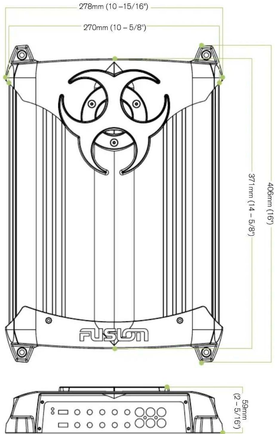
PP-AM10001
text_image
278mm (10 - 15/16") 270mm (10 - 5/8") 371mm (14 - 5/8") 406mm (16") FUSION 59mm (2 - 5/16)AMPLIFIER DIMENSIONS
MONOBLOCK AMPLIFIER
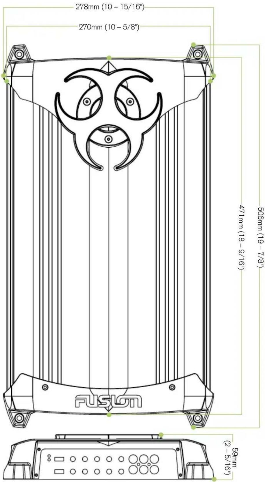
PP-AM15001
text_image
278mm (10 - 15/16") 270mm (10 - 5/8") 471mm (18 - 9/16") 506mm (19 - 7/8") FUSGN (2 - 5/16") 59mmAMPLIFIER DIMENSIONS
MONOBLOCK AMPLIFIER
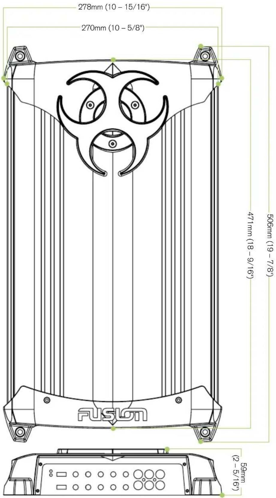
PP-AM20001
text_image
506mm (19-7/8") 471mm (18-9/16") 270mm (10-5/8") 278mm (10-15/16") 59mm (2-5/16")AMPLIFIER DIMENSIONS
2 CHANNEL AMPLIFIER
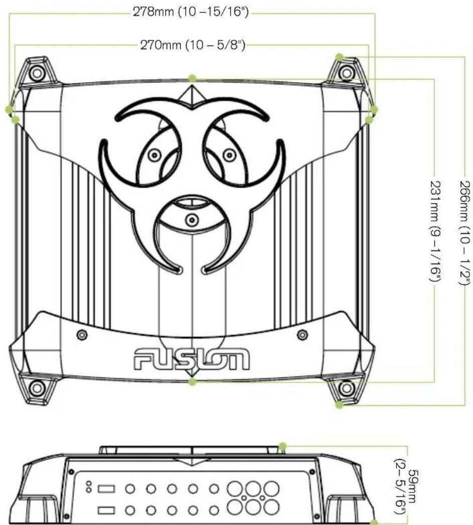
PP-AM4002
text_image
278mm (10 - 15/16") 270mm (10 - 5/8") 231mm (9 - 1/16") 266mm (10 - 1/2") FUSION (2-5/16") 59mmAMPLIFIER DIMENSIONS
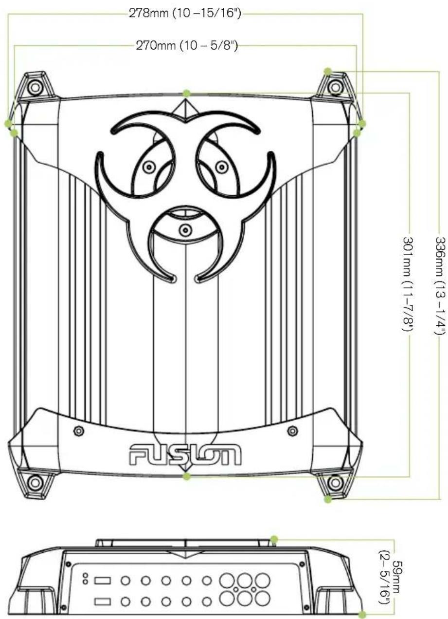
2 CHANNEL AMPLIFIER
PP-AM9002
text_image
278mm (10 -15/16") 270mm (10 - 5/8") 301mm (11-7/8") 336mm (13-1/4") FUSION 59mm (2-5/16)AMPLIFIER DIMENSIONS
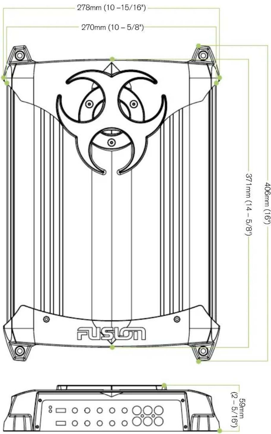
2 CHANNEL AMPLIFIER
PP-AM12002
text_image
278mm (10 -15/16") 270mm (10 - 5/8") 371mm (14 - 5/8") 406mm (16") FUSION 59mm (2 - 5/16"AMPLIFIER DIMENSIONS
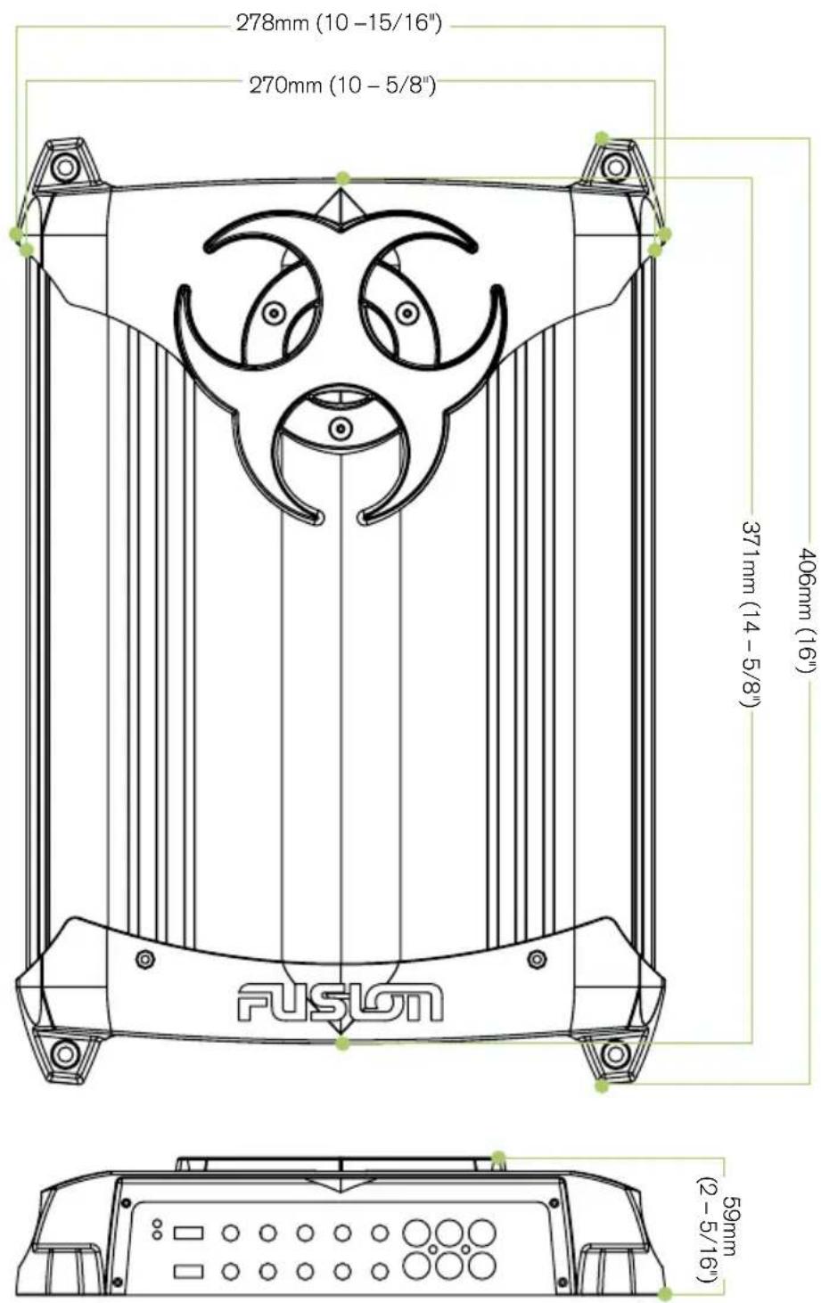
4 CHANNEL AMPLIFIER
PP-AM8004
text_image
278mm (10 -15/16") 270mm (10 - 5/8") 371mm (14 - 5/8") 406mm (16") FUSION 59mm (2 - 5/16)AMPLIFIER DIMENSIONS
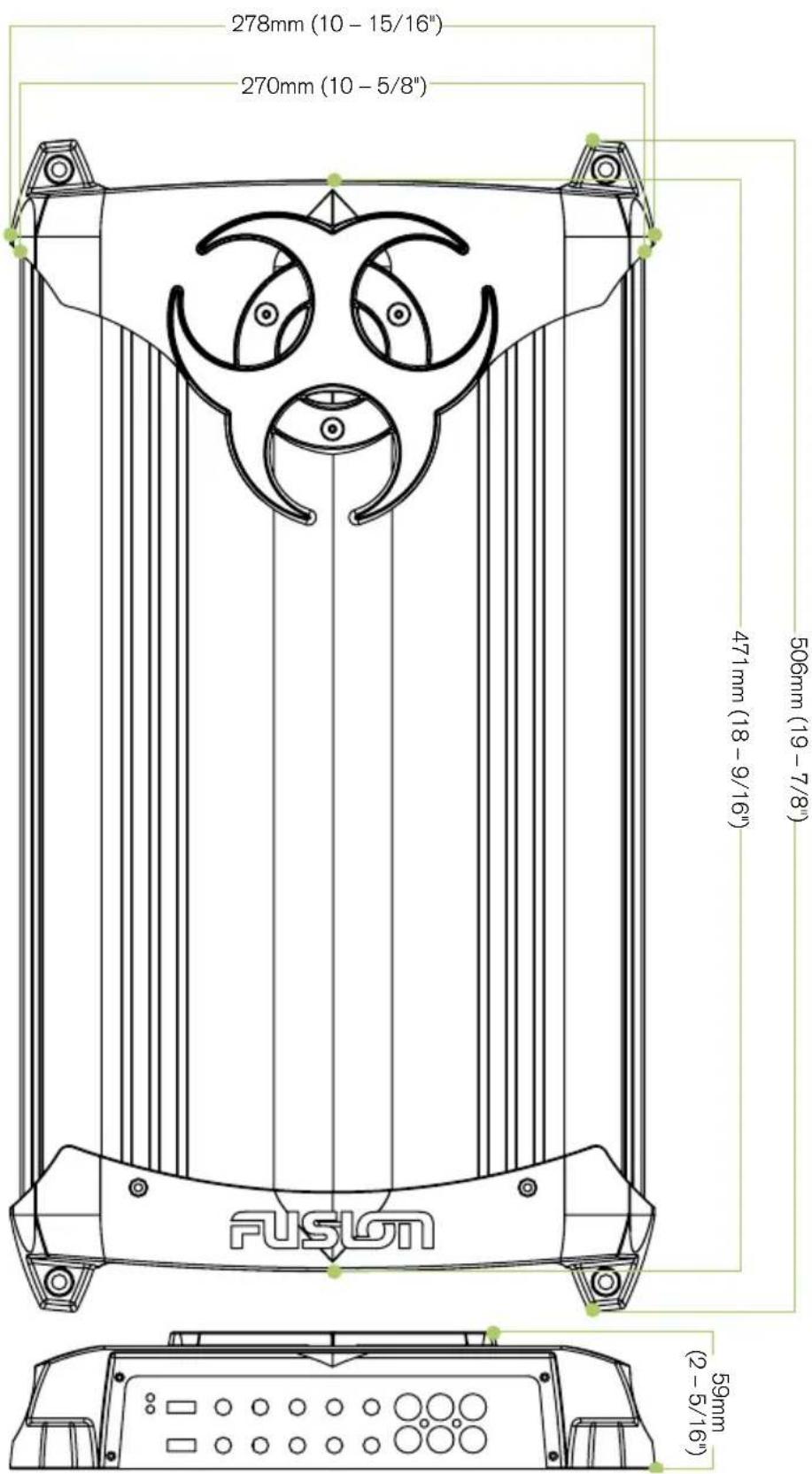
4 CHANNEL AMPLIFIER
PP-AM16004
text_image
278mm (10 - 15/16") 270mm (10 - 5/8") 471mm (18 - 9/16") 506mm (19 - 7/8") FUSION (2 - 5/16") 59mmINSTALLATION
Before any wiring and installation is performed, FUSION recommends you first plan the complete installation. Look at wiring routing, amplifier location and fitment. Please re-check the installation at completion.
Appropriate mounting is very important for prolonged life expectancy of any amplifier. Select a location that allows enough space so sufficient airflow is maintainable and a location that provides protection from moisture. Keep in mind that an amplifier should never be mounted upside down. Upside down mounting will compromise heat dissipation through the heatsink and could engage the thermal protection circuit.
Excessive heat will shorten your amplifier's life. To maximise heat dissipation, be sure to leave at least 2.5 inches of clearance around the amplifier. If space is of the essence and the amplifier must be mounted in an enclosed or restricted area, a small 3" fan should be used in correspondence with a duct so the heat can flow past the heatsink.
WARNING: Do not mount any amplifier on a subwoofer enclosure, as extended exposure to vibration may cause malfunction of the amplifier.
To avoid scratching your new FUSION Amplifier, pre-drill the mounting holes with either a 3mm or 9/64" diameter drill bit and use the screws supplied in the accessory kit..
INSTALLATION WARNING
1: Ensure the vehicle 12 volt lead is removed from the battery before any equipment is connected.
2: Investigate the vehicle's gas tanks, brake lines and electrical wiring locations before you begin installation.
3: Attach the product securely to the vehicle to prevent damage in the event of an accident.
4: Ensure all wiring is protected to avoid damage or pinching of the cables.
WIRING
Make sure before any connection is made to the amplifier or source unit, ensure that you turn the audio system off. Failure to do so could result in either the stock system or your new FUSION product being damaged. FUSION does not warranty damaged amplifiers due to incorrect installation.
When wiring the FUSION amplifier, ensure that the wires are away from sharp objects and that rubber grommets and insulated bungs are used when wiring through door jams and any other steel panels. FUSION recommends using 4 gauge power and ground wire for power installation. Please see power cable calculator (Fig.1).
Ensure that when connecting the wires to the speakers and audio system, the terminals and connections are protected from the vehicle chassis and shorting to each other. If the wires short together or touch the vehicle chassis, the audio system could be damaged.
POWER CABLE CALCULATOR
| TOTAL AMPERAGE | 0-4 FT 4-7 FT 7-10 FT 10 -13 FT 13-16 FT 16-19 FT 19-22 FT 22-28 FT | |||||||
| 0 – 20 14 12 12 10 10 8 8 8 | ||||||||
| 20 – 35 12 10 8 8 6 | 6 6 4 | |||||||
| 35 – 50 | 10 | 8 | 8 | 6 | 4 | 4 | 4 | 4 |
| 50 – 65 | 8 | 8 | 6 | 4 | 4 | 4 | 4 | 2 |
| 65 – 85 | 6 | 6 | 4 | 4 | 2 | 2 | 2 | 0 |
| 85 – 105 | 6 | 6 | 4 | 2 | 2 | 2 | 2 | 0 |
| 105 – 125 | 4 | 4 | 4 | 2 | 0 | 0 | 0 | 0 |
| 125 – 150 | 2 | 2 | 2 | 0 | 0 | 0 | 0 | 0 |
The above chart shows cable gauges to be used, if no less than a 0.5 volt drop is acceptable. If aluminium wire or tinned wired is used, the gauges should be of an even larger size to compensate. Cable gauge size calculation takes into account terminal connection resistance.
Fig.1
CONNECTION
Note: Ensure the audio system is off during the installation of FUSION product. Once the installation is complete FUSION recommends that you turn the volume of the source unit up slowly so as not to damage the speakers. Please recheck the complete installation prior to turning the audio system on.
text_image
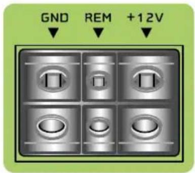
GND REM +12VFUSION amplifiers should be wired directly to the vehicle battery using the appropriate sized cable. Start at the vehicle battery and run the power cable through to the amplifier. FUSION recommends the use of grommets when passing the power cable through any metal wall, and to avoid sharp corners or sharp body parts that may easily cut through the insulation on the cable.
Avoid running the power cable over engine components or near heater cores. The use of an inline fuse or circuit breaker is essential. This will prevent the risk of a potential fire caused by a short circuit in your power cable. Connect the fuse holder or circuit breaker as close to the battery positive terminal as possible. Use a fuse or circuit breaker of equal value as that found on the chassis of your FUSION amplifier. You may now connect the cable to the battery, but remember to leave the fuse out or circuit breaker off until all other cable connections are made.
GROUND
When grounding your FUSION Amplifier locate a metal area close to the amplifier that is a good source of ground (preferably the floor pan). Once again, investigate the area you wish to use for electrical wires, vacuum lines, and brake or fuel lines. Use either a wire brush or sandpaper to eliminate unwanted paint. This will allow a better contact for your ground. Use the same gauge cable for the ground as you did for the power. Secure the ground cable to the body using a bolt, star washer and nut. Spread silicon over the screw and bare metal to prevent rust and possible water leaks. Now it's time to connect the power and ground cables to the amplifier. Cut both cables to length. Loosen the +12V and the GND connections on the amplifier. Terminate the ground first, and then the +12V. Make sure that you terminate them into the correct terminals. Now tighten the screws down securely.
REMOTE TURN-ON
This terminal must be connected to a switched +12V source. Typically, remote turn-on leads are provided at the headunit which will turn the amplifier on and off in correspondence with the source. If the head unit does not have a remote turn-on lead, then a power antenna wire can be used. If neither of these leads are present on the head unit then a switched +12V supply must be used, like the ACC +12V.
Run a minimum of 18 gauge wire from the amplifier location to the source of the switched +12V lead. If possible, route this wire on the same side of the vehicle as your power cable. Connect the source remote output to the wire. Go back to the amplifier and cut the wire to length. Loosen the screw terminal marked REM on the amplifier using a Hex Phillips type screwdriver. Slip the wire into the connector and tighten the screw securely.
text_image
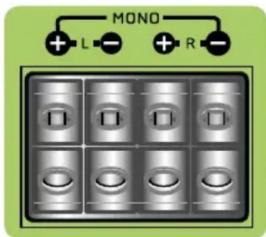
MONO + L - + R -Keep in mind FUSION PowerPlant Amplifier series are high power amplifiers and not high current amplifiers. In other words, they require a minimum impedance of 2 ohms STEREO and 4 ohms bridged MONO to operate trouble free. Too low of impedance could send your FUSION amplifier into protection mode and/or damage the amplifier.
SPEAKER WIRING
Choose the correct speaker wire for your application. Most applications will require a minimum of 16 gauge. Route the speaker wire taking the same precautions you took when you ran the power cables. Terminate these wires at the speaker end by using insulated speaker terminals (not supplied) or by soldering the connection. Make sure the speaker connections are positive to positive and negative to negative. At the amplifier end, use a Hex type screwdriver to loosen the speaker terminals on the amplifier. Connect the speaker wires and tighten the screws securely. Check to make sure you've maintained proper polarity and balance.
text_image
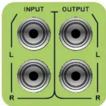
INPUT OUTPUT L L R RRCA INPUT CONNECTION
LOW LEVEL INPUTS
Choose the correct length and style of RCA interconnects for your needs. The FUSION range of RCA's gives you a variety of alternative solutions. These have multiple layers of shielding or are a twisted pair variety for better noise rejection (consult your FUSION dealer if unsure which to purchase).
Be extra careful with your RCA interconnects. Car environments are notorious for poorly insulated wires. This means that hiss, engine noise, and fan noise can easily be picked up through RCA cables if run incorrectly. Avoid running your RCA's near large wire looms and electric fans if possible. Run your RCA cables on the opposite side of the vehicle to the power cable. Be sure to check for correct balance. (Red is right and Black or White is left).
LEVEL CONTROL
The LEVEL control, allows you to match the input level of the amplifier to the output level of your head unit. Matching the input can be accomplished in three simple steps:
1: Turn the LEVEL control on the amplifier to minimum.
2: Turn up the headunit and adjust to 3/4 maximum volume ensuring that the BASS and TREBLE are set to zero.
3: Adjust the LEVEL control until desired volume is achieved without audible distortion. Remember, the gain control is not a volume control. Ignoring the three steps above may leave you with damaged speakers and/or a damaged amplifier.
CONTROL DESCRIPTIONS
MONOBLOCK AMPLIFIER
PP-AM10001, PP-AM15001, PP-AM20001
text_image
PWR BASS BOOST PHASE LP SUBSONIC LEVEL INPUT OUTPUT REMOTE ① ② ③ ④ ⑤ ⑥ +40 -1240 -10Hz 40Hz 30Hz 70Hz 80Hz 6V 4.5V R R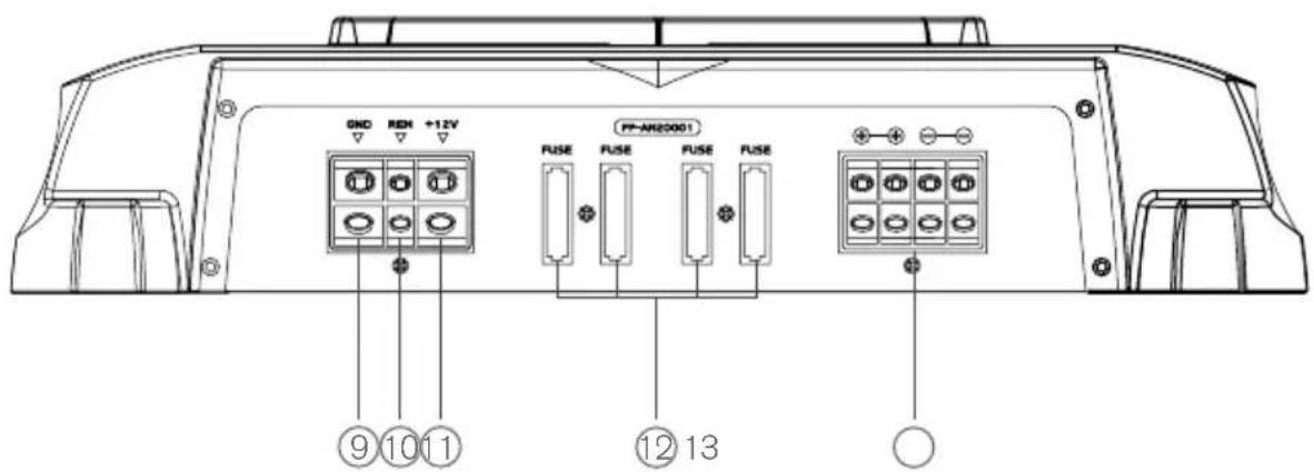
text_image
GND REM +12V FUSE FUSE FUSE FUSE PP-AN20001 ⑨⑩⑪ ⑫⑫⑬ ○1 POWER AND STATUS LED'S:
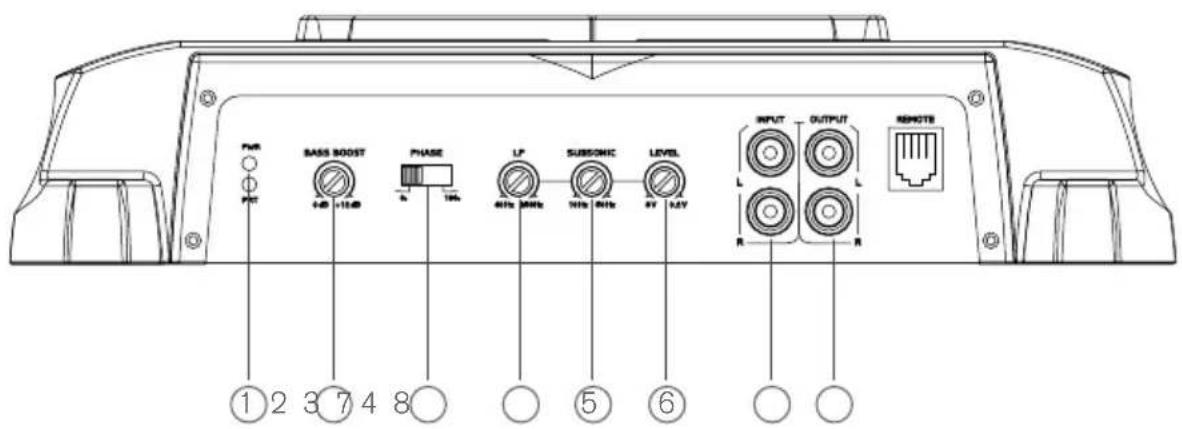
This displays 'Green' if the amplifier has been correctly powered up and 'Red' if any faults are present.
2 BASS BOOST:
This is a variable control to increase the bass boost at 45Hz from 0 - +12dB of gain, adjust to suit.
3 PHASE SWITCH:
Select the phase switch to 0 or 180 degree to adjust the in phase or out of phase subwoofer direction to the vehicles system.
4 LOW PASS:
Ensure the crossover frequency is set at 100Hz or below. This feature is designed to filter out all mid to high frequencies that only full range speakers should produce.
Note: Failure to do so could result in speaker damage.
5 SUBSONIC:
This is a variable control that filters out all sub bass frequencies below the set point at 12dB/Octave.
6 LEVEL:
This allows level adjustment of the input signal. Use this control to correctly match the head unit to the amplifier. To set this control correctly, turn the amplifier level to MIN and the head unit to 3/4 volume, with the bass and treble on zero, then slowly turn up this amplifier level control towards the MAX end of the control. Note: If the sound becomes distorted, turn this control down.
7 RCA INPUT:
Connect these RCA connectors to a head unit with a low level output connection.
8 RCA OUTPUT:
Use these RCA output connectors to connect to a secondary amplifier. This output is a pass-thru connection derived from the RCA input connector so the signal level and frequency response is the same as the original input signal.
9 GROUND INPUT:
Connect directly to the vehicle's chassis via a 4 gauge power cable.
Note: This is the first wire to connect when wiring up an amplifier. Damage could result if this is not done.
10 REMOTE INPUT:
This terminal is for turning the amplifier on and off. The remote input requires a switched positive (+12V) to power 'ON' the amplifier. This can be found on the rear of the head unit in the form of a electric antenna output, or a remote on output. If not available you can wire to the ACC position on the key.
11 +12V INPUT:
Connect directly to the vehicle battery positive (+) terminal via an 4 gauge power cable, with an inline fuse or circuit breaker at the battery end.
Note: This is the last wire to connect up during installation, damage could result if this is not done.
12 FUSES:
Please ensure correct type of fuse is fitted, as specified in this manual.
Note: PP-AM10001 has 2 x 35A fuses, PP-AM15001 has 4 x 25A fuses, PP-AM20001 has 4 x 25A fuses.
13 SPEAKER OUTPUT:
See 2/1 channel installation diagrams on page 26 for correct speaker connection.