
CA-IP500 - Car radio Fusion - Free user manual and instructions
Find the device manual for free CA-IP500 Fusion in PDF.


| Product Type | Car Stereo |
| Brand | Fusion |
| Model | CA-IP500 |
| Dimensions | Standard 1-DIN (178 x 50 x 160 mm) |
| Weight | Approx. 1.5 kg |
| Power Supply | 12V DC (10A max) |
| Amplifier | Integrated, 4x50W peak output |
| Tuner | AM/FM with 30 presets |
| Media Playback | CD, CD-R/RW, MP3, WMA |
| USB Port | Front USB for play and charge (1A) |
| Auxiliary Input | 3.5mm front aux |
| Bluetooth | Hands-free calling and audio streaming |
| Display | LCD with white illumination |
| Remote Control | Included, infrared |
| Installation | DIN mount with included hardware |
| Maintenance | Clean with a soft dry cloth; avoid liquids |
| Safety | Fuse protection (5A inline fuse) |
| Spare Parts | Contact Fusion customer service |
| General Notes | Compatible with standard car wiring harness (ISO) |
Frequently Asked Questions - CA-IP500 Fusion
User questions about CA-IP500 Fusion
0 question about this device. Answer the ones you know or ask your own.
Ask a new question about this device
Download the instructions for your Car radio in PDF format for free! Find your manual CA-IP500 - Fusion and take your electronic device back in hand. On this page are published all the documents necessary for the use of your device. CA-IP500 by Fusion.
USER MANUAL CA-IP500 Fusion
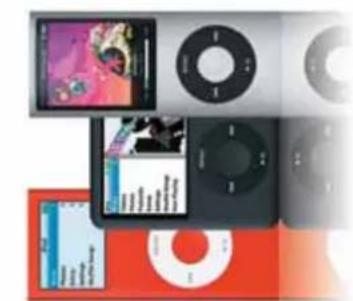
COMPATIBLE WITH THE FOLLOWING IPOD MODELS:
iPod nano:
Gen 2, Gen 3, Gen 4
iPod touch:
Gen 1, Gen 2
iPod classic:
Gen 5, Gen 6, Gen 7

natural_image
Three electronic devices: a red and black iPod, a black-and-white photo album, and a silver Apple Music player (no visible text or symbols on devices themselves)• BASIC OPERATIONS....pg 7
BASIC OPERATIONS....pg 7
SETUP MENU....pg 8
GENERAL SETUP....pg 8
AUDIO SETUP....pg 10
DISPLAY SETUP....pg 10
RDS SETUP....pg 11
RADIO OPERATION....pg 12
• BASIC OPERATIONS....pg 7
SETUP MENU....pg 8
GENERAL SETUP....pg 8
AUDIO SETUP....pg 10
DISPLAY SETUP....pg 10
RDS SETUP....pg 11
RADIO OPERATION....pg 12
iPOD OPERATION....pg 13
AUX OPERATION....pg 14
INSTALLATION GUIDE ...... pg 14
TECHNICAL SPECIFICATIONS....pg 18
NOTES ...... pg 19
WARRANTY....pg 22
Version 3.0
2
CONTENTS
- PRECAUTIONS & MAINTENANCE....pg 4
- DETACHABLE FRONT PANEL....pg 6
iPOD OPERATION....pg 13
AUX OPERATION....pg 14
INSTALLATION GUIDE ...... pg 14
TECHNICAL SPECIFICATIONS....pg 18
NOTES ...... pg 19
WARRANTY....pg 22
3

(using a paper clip or similar) (using a paper clip or similar) (minute. Please remove Front Panel and press "RESET" Button in location shown in the event of a malfunction, where normal operation is not automatically restored within 1
TOUBLUE SHOOTING
• Before inserting iPod.
No responsibility can be taken for use of the unit other than under normally expected operating conditions in conjunction with fully functional and undamaged iPod units which have been manufactured and authorised by Apple Inc.
• This unit has been tested with all compatible authentic iPod models under normal expected operating conditions, free from any pre-existing defects in either the unit or the iPod.
“Supply of this product only surveys a license for private, non-commercial use and does not convey a broadcasting (terrestrial, satellite, cable and/or other media), broadcasting / streaming via internet, interests and/or other networks or in other electronic content distribution systems, such as publicly broadcasting or funding-demand applications. An independent license for such use is required. For details, please visit
„MEFG Layer-3 audio coding technology licensed from Faunohoter II5 and Thompson.“
Apple, the Apple logo, iPod and iTunes are Trademarks of Apple Computer, Inc. registered in the U.S. and other countries.
For correct operation in America, Tuner Frequency stepping needs to be changed, Default setting is Europe), to Change: SELECT: Menu - General - Area - America 1
TUNER SETTING
PRECIFICATIONS & MAINTENANCE
FCC COMPLIANCE STATEMENT
This device complies with part 15 of the FOG rules. Operation is subject to the following two conditions:
(1) This device may not cause harmful interference, and
[2] This device must accept any interference received, including interference that may
cause undesired operation.
- When cleaning the interior of the vehicle, do not get water or cleaning fluids on the
• Do not attempt to open the unit chassis. There are no user serviceable parts or
adjustments 2
- This unit has been tested with all compatible authentic iPod models under normal
http://www.mp3licensing.com"
[Non-Text]
operating condiments in conjugation with fully superficial and undesarred flood units
which have been manufactured and authorised by Apple Inc.
Please ensure iPod dock conrector is clean, dry & free from damage.
Check that unit iPod dock is free from obstructions.
Insert correct sleeve completion to match your iPod
[Never insert iPod without a correct sleeve.]
• Ensure iPod is interested with display facing upwards. Never force your iPod into the
dock, if the iPod does not mate with reasonable ease the sleeve/ iPod combination is
most likely incorrect.
• Always remove your iPod from the unit when not in use & do not leave in your vehicle.
this in turn prevents risk of theft or damage as vehicle cabins can reach extreme
temperatures.
• Do not remove iPod or use stereo in a distractive manner whilst operating the vehicle,
check and obey all traffic laws in association with use.
• Take care when removing iPod from unit as surfaces may be warm.
DETACHABLE FRONT PANEL
Removing The Front Panel

-
Press the panel lock button to open the panel.
-
Remove the panel by pulling from RIGHT side.
-
Always store the detached panel in the supplied carrying case when not in use.
Keep in mind
- If any function does not work, open the front panel and re-close.
Do not touch the contact pins on the rear of the front panel, as this can cause contact problems and they do become hot through normal use. If the contacts should become dirty, they can be cleaned carefully with a soft cloth.
- Do not expose the front panel to extreme heat or cold.
- Petrol and other solvents must not come into contact with the front panel.
- The front panel must not be pressed hard, or dropped.
- Never take the front panel apart.
Attaching The Front Panel
- With door in open position, engage hinge pivot at Left side then align and insert the
other end.
Long key press: Intro Scan, Shuffle, Repeat Track, Repeat Folder (iPod) Short key press: Enter iPod Navigation Menu (iPod)
Push up
FM radio pre-set group (FM1-3),
BASIC OPERATIONS

-
PANEL OPEN BUTTON
-
VOLUME
Turn: Volume control
Press: Mute (or pause function for iPod)
- EQ / LOUD
Short key press: Preset EQ type selection
Off - Pop - Classic - Rock - Jazz - Voice - Club - Dance - Techno - Live - Party - Soft - User 1 - User 2 - User 3 Long key press: Loud On / Off
- PWR/SRC
Long key press: Power On/Off Short key press: Play mode sel
Radio - iPod - AUX
- MENU
Short key press: Access to various set-up functions
General - Audio - Display - RDS
- JOYSTICK
Press
Short key press: Preset Recall, Select [Radio]
Long key press: Preset Store [Radio]
□
CLOCK ADJUSTMENT
Turn the joystick encoder to select the CLOCK ADJUSTMENT icon, confirm your selection by passing the joystick.
Local - Security - Clack Adjustment - Mode Scan - Menu Reset
Set the time by pushing the joystick right / left to select her/min and turn the joystick
encoder to change the time. Press the joystick to confirm the time.
CAUTION: : User must memorise their own security code. If number is lost unit will need to be returned to service centre.
the joystick encoder to select the SECURITY icon, confirm your selection by pressing
Local - Security - Clock Adjustment - Mode Scan - Menu Reset
- Turn the joystick encoder to select OFF, confirm your selection by pressing the joystick
Turning Head Unit on when Security On's activated
When the Security On' function is activated, you will be
whenever you remove and apply power to unit.
1) Correct input of security code: Normal operation and POWER ON operation continuously required.
2) Incorrect input of security code: Operation is not available and code input is
Security OFF
SECURITY Setup
AM radio pre-set group (AM 1-2).
Push Left
Push joystick left: Seek down [radio], Track down [iPod]
Turn joystick encoder left: Manually tune down [radio], Track down [ipod]
Push Right
Push joystick right: Seek up (radio), track up (!Pod)
Turn joystick encoder right: Manually tune up (radio), Track up (ipod)
- DISP/TA (RDS)
Short key press: Display mode selection
ID3 Display - Screen Saver - Spectrum Analyzer
Alternative ROS Display Mode (Radio)
Long key press: TA on / off (ROS)
SETUP MENU
in the SETUP menu, you can change various basic set up configurations. Press the MENU button to enter the SETUP screen.
Turn the joystick encoder to scroll through the SETUP screen, confirm your selection by pressing the joystick General - Audio - Display - ROS
GENERAL SETUP
Turn the joystick encoder to select the GENERAL icon in the SETUP screen, confirm your selections by pressing the joystick.
General - Audio - Display - ROS
LOCAL Setup
Turn the joystick encoder to select the LOCAL icon, confirm your selection by pressing the
loystick.
Local - Security - Clack Adjustment - Mode Scan - Menu Reset
Turn the joystick encoder to select ON, confirm your selection by pressing the joystick.
∞
CAUTION: If Screen saver is disabled, static graphics may cause uneven screen ageing.
- After the chosen DISPLAY setting by turning the joystick encoder. Confirm the alteration by pressing the joystick. - Pass the MENU button to go back to the previous SETUP screen
Turn the joystick encoder to select the ROS icon in the SETUP screen, confirm your selection by pressing the joystick.
General - Audio - Display - ROS
You can alter the following settings in the RDS menu:
AF
- Regional
- Program Type
- TA Volume
Clock time
- Turn the joystick encoder to select the RDS setting you wish to alter, confirm your selection by pressing the joystick
- After the chosen RDS setting by turning the joystick encoder. Confirm the iteration by
pressing the joystick
- Press the MENU button to go back to the previous SETUP screen
PS (Program station name):
- If RDS station is selected, PS [Program Station name] is displaced when RDS signal is
properly received.
Since PS is stored to each preset channel memory, if preset channel is selected then PS
name is displayed instead of the frequency.
RDS SETUP
MENU RESCT
To reset every menu setting to the factory default, turn the joystick encoder to select the
MENU RESET icon, confirm your selection by pressing the joystick
Local - Security - Clack Adjustment - Mode Scan - Menu Reset
AUDIO SETUP
Turn the joystick encoder to select the AUDIO icon in the SETUP screen, confirm your selection by pressing the joystick
General - Audio - Display - ROS
You can alter the following settings in the AUDIO menu:
-Trade/Mid/Bass
- Fader/Balance
- User EQ Settings
- High Pass Filter/Low Pass Filter
Wooster
- SRS WOW
- Turn the joystick encoder to select the AUDIO setting you wish to alter, confirm your
selection by pressing the joystick
- After the chosen ALUDI0 setting by turning the joystick encoder. Confirm the alteration by
pressing the joystick.
- Press the MENU button to go back to the previous SETUP screen
DISPLAY SETUP
Turn the joystick encoder to select the DISPLAY icon in the SETUP screen, confirm your selection by pressing the joystick
General - Audio - Display - ROS
You can alter the following settings in the DISPLAY menu:
- Dimmert
- Screen Saver
- Graphic EQ Style
- Button illumination/LED colour
- Turn the joystick encoder to select the DISPLAY setting you wish to alter, confirm your selection by pressing the joystick
RADIO OPERATION
Radio Mode Selection
Press the SOURCE button to select RADIO mode.
Radio - iPod - AUX
Band Selection
Push the joystick up / down to select the band Push joystick up
FM1 - FM2 - FM3
Push joystick down
AM1 - AM2
Automatic Tuning Mode
Push the joystick left / right for automatic tuning (left = seek down, right = seek up). It will continuously search until the next radio station is detected.
Manual Tuning Mode
Turn the joystick encoder left / right to manually tune each radio station. Frequency changes one step whenever joystick encoder is turned.
Preset Memory
You can store radio frequencies in the preset memory.
- Search for the radio frequencies by using the automatic or manual tuning mode.
- Press and hold the joystick until the PRESET screen is shown.
- Turn the joystick encoder to select a PRESET memory number, confirm your selection by
pressing the joystick.
Preset Recall
To listen to a radio frequency stored in the preset memory;
- Press the joystick. The PRESET memory screen will appear.
- In the PRESET memory screen, turn the joystick encoder to select the preset number you
want. Confirm your selection by pressing the joystick.
- or Push joystick left/right to index.
TUNER SETTING
For correct operation in America, Tuner Frequency stepping needs to be changed, Default setting is Europe, to Change:
SELECT: Menu - General - Area - America 1
iPod Operation
The joystick encoder operates in the same manner as the clickwheel on the iPod. - Press joystick to enter menu
- Turn the joystick encoder to s
- Press the joystick to select a menu option
Press the MENU button to return to the previous menu
12
iPod
iPod
Before inserting your iPod into the CA-IP500 you must first insert the correct sleeves to match iPod model.
The differen
The different sleeve combinations are outlined in the chart below:
| iPod Top sleeve Bottom sleeve | ||
| classic, 5th Gen [30gb] A A | ||
| classic, 5th Gen [60/80gb] A B | ||
| classic, 6th Gen [80gb] B A | ||
| classic, 6th Gen [160gb] B B | ||
| classic, 7th Gen B A | ||
| touch, 1st Gen, 2nd Gen D D | ||
| nano, 2nd Gen | C C | |
| nano, 3rd Gen, + Adapter | A A | |
| nano, 4th Gen | E | E |
Notes:
For the iPod nano (3rd gen), the iPod must be placed inside the adaptor sleeve, and
then placed inside Dock sleeve combination A.
For iPod insertion/removal we recommend that you 1st remove Front panel to
improve access. Due to iTouch design, the fit is a little tighter than the other models
aware this does not affect the correct operation of either Fusion or Apple product.
Before inserting iPod,
Please ensure iPod dock connector is clean, dry & free from damage.
Check that unit iPod dock is free from obstructions.
Insert correct sleeve combination to match your iPod
Never insert iPod without a correct sleeve.
Ensure iPod is inserted with display facing upwards, Never force your iPod into the
dock, if the iPod does not mate with reasonable ease the sleeve/iPod combination is
iPod Mode Selection
Press the SOURCE button to select iPOD mode.
Radio - iPod - AUX
13
Additional Functions
Additional functions available while the iPod is playing
Intro Scan - Shuffle - Repeat Track - Repeat Folder
To activate additional functions when the iPod is playing;
- Press and hold the joystick and the iPod FUNCTIONS screen will appear - Select a function by using the joystick encoder, confirm your selection by pressing the joystick
AUX OPERATION
Aux Connect
Connect an audio source to the AUX cable in the rear panel.
Aux Mode Selection
Press the SOURCE button to select AUX mode.

INSTALLATION GUIDE
-
Disconnect the negative [-12 V] lead from your battery to avoid potential damage to
-
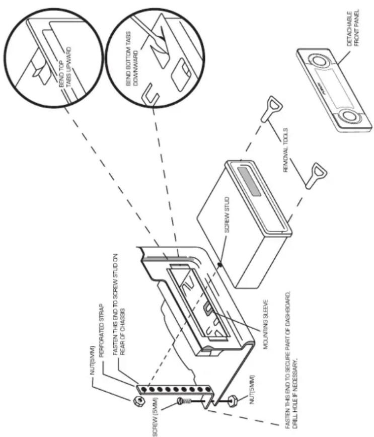
Remove the detachable front panel and slide the mounting sleeve off the chassis using the removal keys provided.
-
Insert the mounting sleeve into the mounting hole and bend the locating tabs out to secure the sleeve into the dash.
-
Ensure you follow the wiring Table (see page 17). Incorrect connections may cause damage to the unit and the vehicle's electrical system. (and is not covered under
-
After all wiring connections are completed attach the front panel to confirm operation.
-
Slide the unit into the mounting sleeve ensuring it locks into place and attach the perforated support strap [supplied] to the screw stud on the rear of the chassis using the hex nut provided. Fasten the opposite end of the strap to a secure location.
Dashboard Installation
NOTE:
This unit is carefully designed to protect & minimise the temperature of your iPod during use. An internal fan will operate automatically when an iPod is connected,
- For installation, please ensure rear Fan vent holes are not obstructed & adequate clearance is available to allow free air flow.
CAUTION! : The rear of the unit must be supported to prevent damage to the dash and/or
improper operation due to vibration.
Aux Harness Diagram

flowchart
graph TD
    A["Power Supply"] --> B["XM"]
    A --> C["WOOFER"]
    A --> D["AUX"]
    A --> E["LINE OUT FRONT"]
    A --> F["LINE OUT REAR"]
    B --> G["Red - Right"]
    B --> H["WHITE - Left"]
    B --> I["BLE"]
    C --> J["Red - Right"]
    C --> K["WHITE - Left"]
    D --> L["Red - Right"]
    D --> M["WHITE - Left"]
    E --> N["White - Left"]
    E --> O["RED - Right"]
    F --> P["White - Left"]
    F --> Q["RED - Right"]
Aux Connection Table
Power Connector Diagram
![FUSE 1 GND (+ve) IGNITION [sw] TELE. MUTE N.C SPEAKER RR+ SPEAKER FR+ SPEAKER FL+ SPEAKER RL- BATTERY (+ve) REMOTE TURN ON ILLUMINATION POWER ANTENNA SPEAKER RR- SPEAKER FR- SPEAKER FL- SPEAKER RL-](/content/2026/05/962339/images/d7aede8f7c90034aadabe0f90d4ed42d68b165f96fb784594c8fd2cee5019288.jpg)
Power Connector Table
| Description Colour | |
| BATTERY (+ve) YELLOW | |
| REMOTE TURN ON BLUE/WHITE | |
| ILLUMINATION ORANGE | |
| POWER ANTENNA BLUE | |
| SPEAKER RR- | VIOLET/BLACK |
| SPEAKER FR- | GRAY/BLACK |
| SPEAKER FL- | WHITE/BLACK |
| SPEAKER RL- | GREEN/BLACK |
| GND (-ve) | BLACK |
| IGNITION (switched) | RED |
| TELE. MUTE | BROWN |
| N.C | - |
| SPEAKER RR+ | VIOLET |
| SPEAKER FR+ | GRAY |
| SPEAKER FL+ | WHITE |
| SPEAKER RL+ | GREEN |
| Pin NO Signal | |
| 1 Line | Out R.R |
| 2 Line | Out L.R |
| 3 Line | Out R.F |
| 4 Line | Out L.F |
| 5 Aux in Left | |
| 6 Ground R.R | L.R |
| R.F | |
| L.F | |
| 7 Ground Aux leftGround Aux right | |
| 8 Aux in Right | |
| 9 Ground WooferXM RightXM Left | |
| 10 Woofer Out | |
| 11 XM Right | |
| 12 XM Left | |
Rear Panel Diagram


natural_image
Three labeled illustrations of electrical connectors: a wire, a hand with wires, and a cable (no text or symbols present)- POWER cable

natural_image
Two types of electrical connectors shown in separate rounded square frames: a cable and a multi-pin connector (no text or symbols visible)- AUX cable

1. FM/AM Antenna
TECHNICAL SPECIFICATIONS
Size : 7" [W] x 2" [H] x 6-1/2" [D]
178 mm x 50 mm x 160 mm
Operating voltage: 12Volt DC, Negative Ground
Fuse ratings: Constant (Yellow wire) 15AMP.
Switched (Red wire) : 1.0 AMP.
Output power: 50 watts x4 channels
Output: RCA line-level outputs.
Output impedance: 4-8 ohm's
Line - level output : 4 V
Tuning range :
| America Europe | |
| AM : 530 - 1,710 kHz[10 kHz step] | AM : 522 - 1,620 kHz[9 kHz step] |
| FM : 87.5 - 108.0 MHz[100 kHz step] | FM : 87.5 - 108.0 MHz[50 kHz step] |
Sensitivity: AM: 20 V
FM : < 5 V
18
NOTES
19
NOTES
NOTES
| ...... | |
| ...... | |
| ...... | |
| ...... | |
| ...... | |
| ...... | |
| ...... | |
| ...... | |
| ...... | |
| ...... | |
| ...... | |
| ...... | |
| ...... | |
| ...... | |
| ...... | |
| ...... | |
| ...... | |
| ...... | |
| ...... | |
| ...... | |
| ...... |
20
THE FUSION PROMISE OF QUALITY
LIMITED 1 YEAR CONSUMER WARRANTY
If a problem develops during the limited warranty period, the consumer should take the following step-by-step procedure:
EXCLUSIONS AND LIMITATIONS
This Limited Warranty applies only to the hardware product manufactured by or for Fusion that can be identified by the "Fusion" trademark, trade name, or logo attached to it. The Limited Warranty does not apply to any non-Fusion hardware product or associated software.
[Non-Text]
FUSION Electronics Limited 'FUSION' warrants this FUSION Head Unit is free from defects in material and workmanship, according to the following terms and conditions:
or replace, at FUSION or FUSION'S
authorised dealer, any defective product or parts thereof with new and return the product to the consumer in working condition.
No charge will be made to the consumer for either parts or labour in repairing or replacing
other parts of labour in repairing of replacing the product. All replaced parts and cosmetic parts should be free of defects at the time of
shipment and, therefore shall not be covered under these limited warranty terms.
Repaired product will be warranted for the balance of the original warranty period or for ninety (90) days from the date of repair,
whichever is longer. All warranty claims must be accompanied with
a copy of this warranty card, and a copy of proof of purchase date.
[Non-Text]
The consumer shall have no coverage or benefits under this limited warranty if any of the following conditions are applicable:
- The product has been subject to: abnormal use, abnormal conditions, improper storage, exposure to excessive moisture or dampness, exposure to excessive temperature or other such environmental conditions, unauthorised modifications, unauthorised connections, unauthorised repair including but not limited to use of unauthorised spare parts in repairs, misuse, neglect, abuse, accident, alteration, improper installation, acts of God, spill of foods or liquids, maladjustment of customer controls or other acts which are beyond the reasonable control of FUSION, including deficiencies in consumable parts such as fuses, and breakage or damage to antennae unless caused directly by defects in materials or workmanship, and normal wear and tear of the product. - FUSION was not notified by the consumer of the alleged defect or malfunction of the product during the applicable limited warranty period.
- The product serial number or the accessory date code has been removed, defaced or altered. - The product was used with or connected to an accessory not supplied by FUSION or fit for use with FUSION product, or used in a manner other than its intended use.
22
- The consumer shall return the product to the place of purchase for repair or replacement processing.
- The consumer shall also be charged for any parts or labour charges not covered by this limited warranty. The consumer shall be responsible for expenses related to reinstallation of the product.
THE BENEFITS CONFERRED BY THIS LIMITED WARRANTY APPLY TO THE EXTENT THAT THEY ARE NOT SUPERCEDED BY ANY OTHER RIGHTS AND REMEDIES UNDER ANY APPLICABLE LEGISLATION THAT CANNOT BE EXCLUDED, OTHERWISE, TO THE EXTENT PERMITTED BY LAW, ANY IMPLIED WARRANTY
IS EXCLUDED AND THE FOREGOING WARRANTY IS THE PURCHASER'S SOLE AND EXCLUSIVE REMEDY AND IS IN LIEU OF ALL OTHER WARRANTIES, EXPRESS OR IMPLIED. TO THE EXTENT PERMITTED BY LAW, FUSION SHALL NOT BE LIABLE FOR INCIDENTAL OR CONSEQUENTIAL DAMAGES OR A LOSS OF ANTICIPATED BENEFITS OR PROFITS, OUT OF USE OR INABILITY TO USE THE PRODUCT.
[Non-Text]
- Some states in America do not allow the exclusion or limitation of consequential damages, so the above limitation and exclusion may not apply to you. This warranty gives you specific legal rights which may vary from state to state. - FUSION neither assumes nor authorises any authorised service centre or any person or entity to assume for it any other obligation or liability beyond that which is expressly provided for in this warranty. - All warranty information, product features and specifications are subject to change without notice.

PUBLISHED BY FUSION ELECTRONICS LIMITED: © Copyright 2008 by FUSION Electronics Limited. All rights reserved. Specifications and design are subject to change without notice.
YOU CAN HELP PROTECT THE ENVIRONMENT! Please remember to respect the local regulations. Hand in the non-working electrical equipment to an appropriate waste disposal center.
23

- COMPATIBLE WITH THE FOLLOWING IPOD MODELS:
- CONTENTS
- TOUBLUE SHOOTING
- TUNER SETTING
- PRECIFICATIONS & MAINTENANCE
- DETACHABLE FRONT PANEL
- BASIC OPERATIONS
- Security OFF
- SETUP MENU
- GENERAL SETUP
- CAUTION: If Screen saver is disabled, static graphics may cause uneven screen ageing.
- General - Audio - Display - ROS
- RDS SETUP
- MENU RESCT
- AUDIO SETUP
- DISPLAY SETUP
- RADIO OPERATION
- iPod
- Radio - iPod - AUX
- Additional Functions
- AUX OPERATION
- INSTALLATION GUIDE
- CAUTION! : The rear of the unit must be supported to prevent damage to the dash and/or
- TECHNICAL SPECIFICATIONS
- NOTES
- THE FUSION PROMISE OF QUALITY
- LIMITED 1 YEAR CONSUMER WARRANTY
- EXCLUSIONS AND LIMITATIONS
Brand : Fusion
Model : CA-IP500
Category : Car radio